KR20200062425A - Seat height adjust apparatus for vehicle seat - Google Patents
Seat height adjust apparatus for vehicle seat Download PDFInfo
- Publication number
- KR20200062425A KR20200062425A KR1020180147147A KR20180147147A KR20200062425A KR 20200062425 A KR20200062425 A KR 20200062425A KR 1020180147147 A KR1020180147147 A KR 1020180147147A KR 20180147147 A KR20180147147 A KR 20180147147A KR 20200062425 A KR20200062425 A KR 20200062425A
- Authority
- KR
- South Korea
- Prior art keywords
- link
- height
- unit
- cushion frame
- gear
- Prior art date
Links
- 230000005540 biological transmission Effects 0.000 claims description 39
- 239000011324 bead Substances 0.000 claims description 6
- 230000003014 reinforcing effect Effects 0.000 claims description 2
- 230000036544 posture Effects 0.000 abstract description 8
- 230000002787 reinforcement Effects 0.000 description 3
- 230000037237 body shape Effects 0.000 description 1
- 230000002452 interceptive effect Effects 0.000 description 1
- 210000000214 mouth Anatomy 0.000 description 1
Images


Classifications
-
- B—PERFORMING OPERATIONS; TRANSPORTING
- B60—VEHICLES IN GENERAL
- B60N—SEATS SPECIALLY ADAPTED FOR VEHICLES; VEHICLE PASSENGER ACCOMMODATION NOT OTHERWISE PROVIDED FOR
- B60N2/00—Seats specially adapted for vehicles; Arrangement or mounting of seats in vehicles
- B60N2/02—Seats specially adapted for vehicles; Arrangement or mounting of seats in vehicles the seat or part thereof being movable, e.g. adjustable
- B60N2/04—Seats specially adapted for vehicles; Arrangement or mounting of seats in vehicles the seat or part thereof being movable, e.g. adjustable the whole seat being movable
- B60N2/16—Seats specially adapted for vehicles; Arrangement or mounting of seats in vehicles the seat or part thereof being movable, e.g. adjustable the whole seat being movable height-adjustable
- B60N2/18—Seats specially adapted for vehicles; Arrangement or mounting of seats in vehicles the seat or part thereof being movable, e.g. adjustable the whole seat being movable height-adjustable the front or the rear portion of the seat being adjustable, e.g. independently of each other
- B60N2/1807—Seats specially adapted for vehicles; Arrangement or mounting of seats in vehicles the seat or part thereof being movable, e.g. adjustable the whole seat being movable height-adjustable the front or the rear portion of the seat being adjustable, e.g. independently of each other characterised by the cinematic
- B60N2/1821—Combination of Rods and slides
-
- B—PERFORMING OPERATIONS; TRANSPORTING
- B60—VEHICLES IN GENERAL
- B60N—SEATS SPECIALLY ADAPTED FOR VEHICLES; VEHICLE PASSENGER ACCOMMODATION NOT OTHERWISE PROVIDED FOR
- B60N2/00—Seats specially adapted for vehicles; Arrangement or mounting of seats in vehicles
- B60N2/02—Seats specially adapted for vehicles; Arrangement or mounting of seats in vehicles the seat or part thereof being movable, e.g. adjustable
- B60N2/0224—Non-manual adjustments, e.g. with electrical operation
- B60N2/02246—Electric motors therefor
- B60N2/02253—Electric motors therefor characterised by the transmission between the electric motor and the seat or seat parts
-
- B60N2/0232—
-
- B—PERFORMING OPERATIONS; TRANSPORTING
- B60—VEHICLES IN GENERAL
- B60N—SEATS SPECIALLY ADAPTED FOR VEHICLES; VEHICLE PASSENGER ACCOMMODATION NOT OTHERWISE PROVIDED FOR
- B60N2/00—Seats specially adapted for vehicles; Arrangement or mounting of seats in vehicles
- B60N2/02—Seats specially adapted for vehicles; Arrangement or mounting of seats in vehicles the seat or part thereof being movable, e.g. adjustable
- B60N2/0224—Non-manual adjustments, e.g. with electrical operation
- B60N2/0244—Non-manual adjustments, e.g. with electrical operation with logic circuits
- B60N2/0252—Non-manual adjustments, e.g. with electrical operation with logic circuits with relations between different adjustments, e.g. height of headrest following longitudinal position of seat
-
- B—PERFORMING OPERATIONS; TRANSPORTING
- B60—VEHICLES IN GENERAL
- B60N—SEATS SPECIALLY ADAPTED FOR VEHICLES; VEHICLE PASSENGER ACCOMMODATION NOT OTHERWISE PROVIDED FOR
- B60N2/00—Seats specially adapted for vehicles; Arrangement or mounting of seats in vehicles
- B60N2/02—Seats specially adapted for vehicles; Arrangement or mounting of seats in vehicles the seat or part thereof being movable, e.g. adjustable
- B60N2/04—Seats specially adapted for vehicles; Arrangement or mounting of seats in vehicles the seat or part thereof being movable, e.g. adjustable the whole seat being movable
- B60N2/10—Seats specially adapted for vehicles; Arrangement or mounting of seats in vehicles the seat or part thereof being movable, e.g. adjustable the whole seat being movable tiltable
-
- B—PERFORMING OPERATIONS; TRANSPORTING
- B60—VEHICLES IN GENERAL
- B60N—SEATS SPECIALLY ADAPTED FOR VEHICLES; VEHICLE PASSENGER ACCOMMODATION NOT OTHERWISE PROVIDED FOR
- B60N2/00—Seats specially adapted for vehicles; Arrangement or mounting of seats in vehicles
- B60N2/02—Seats specially adapted for vehicles; Arrangement or mounting of seats in vehicles the seat or part thereof being movable, e.g. adjustable
- B60N2/04—Seats specially adapted for vehicles; Arrangement or mounting of seats in vehicles the seat or part thereof being movable, e.g. adjustable the whole seat being movable
- B60N2/16—Seats specially adapted for vehicles; Arrangement or mounting of seats in vehicles the seat or part thereof being movable, e.g. adjustable the whole seat being movable height-adjustable
- B60N2/1605—Seats specially adapted for vehicles; Arrangement or mounting of seats in vehicles the seat or part thereof being movable, e.g. adjustable the whole seat being movable height-adjustable characterised by the cinematic
- B60N2/161—Rods
- B60N2/1615—Parallelogram-like structure
-
- B—PERFORMING OPERATIONS; TRANSPORTING
- B60—VEHICLES IN GENERAL
- B60N—SEATS SPECIALLY ADAPTED FOR VEHICLES; VEHICLE PASSENGER ACCOMMODATION NOT OTHERWISE PROVIDED FOR
- B60N2/00—Seats specially adapted for vehicles; Arrangement or mounting of seats in vehicles
- B60N2/02—Seats specially adapted for vehicles; Arrangement or mounting of seats in vehicles the seat or part thereof being movable, e.g. adjustable
- B60N2/04—Seats specially adapted for vehicles; Arrangement or mounting of seats in vehicles the seat or part thereof being movable, e.g. adjustable the whole seat being movable
- B60N2/16—Seats specially adapted for vehicles; Arrangement or mounting of seats in vehicles the seat or part thereof being movable, e.g. adjustable the whole seat being movable height-adjustable
- B60N2/1635—Seats specially adapted for vehicles; Arrangement or mounting of seats in vehicles the seat or part thereof being movable, e.g. adjustable the whole seat being movable height-adjustable characterised by the drive mechanism
- B60N2/165—Gear wheel driven mechanism
-
- B—PERFORMING OPERATIONS; TRANSPORTING
- B60—VEHICLES IN GENERAL
- B60N—SEATS SPECIALLY ADAPTED FOR VEHICLES; VEHICLE PASSENGER ACCOMMODATION NOT OTHERWISE PROVIDED FOR
- B60N2/00—Seats specially adapted for vehicles; Arrangement or mounting of seats in vehicles
- B60N2/02—Seats specially adapted for vehicles; Arrangement or mounting of seats in vehicles the seat or part thereof being movable, e.g. adjustable
- B60N2/04—Seats specially adapted for vehicles; Arrangement or mounting of seats in vehicles the seat or part thereof being movable, e.g. adjustable the whole seat being movable
- B60N2/16—Seats specially adapted for vehicles; Arrangement or mounting of seats in vehicles the seat or part thereof being movable, e.g. adjustable the whole seat being movable height-adjustable
- B60N2/1695—Seats specially adapted for vehicles; Arrangement or mounting of seats in vehicles the seat or part thereof being movable, e.g. adjustable the whole seat being movable height-adjustable with simultaneous height and inclination adjustment
-
- B—PERFORMING OPERATIONS; TRANSPORTING
- B60—VEHICLES IN GENERAL
- B60N—SEATS SPECIALLY ADAPTED FOR VEHICLES; VEHICLE PASSENGER ACCOMMODATION NOT OTHERWISE PROVIDED FOR
- B60N2/00—Seats specially adapted for vehicles; Arrangement or mounting of seats in vehicles
- B60N2/02—Seats specially adapted for vehicles; Arrangement or mounting of seats in vehicles the seat or part thereof being movable, e.g. adjustable
- B60N2/04—Seats specially adapted for vehicles; Arrangement or mounting of seats in vehicles the seat or part thereof being movable, e.g. adjustable the whole seat being movable
- B60N2/16—Seats specially adapted for vehicles; Arrangement or mounting of seats in vehicles the seat or part thereof being movable, e.g. adjustable the whole seat being movable height-adjustable
- B60N2/18—Seats specially adapted for vehicles; Arrangement or mounting of seats in vehicles the seat or part thereof being movable, e.g. adjustable the whole seat being movable height-adjustable the front or the rear portion of the seat being adjustable, e.g. independently of each other
- B60N2/1803—Seats specially adapted for vehicles; Arrangement or mounting of seats in vehicles the seat or part thereof being movable, e.g. adjustable the whole seat being movable height-adjustable the front or the rear portion of the seat being adjustable, e.g. independently of each other with independent front and/or rear adjustment
-
- B—PERFORMING OPERATIONS; TRANSPORTING
- B60—VEHICLES IN GENERAL
- B60N—SEATS SPECIALLY ADAPTED FOR VEHICLES; VEHICLE PASSENGER ACCOMMODATION NOT OTHERWISE PROVIDED FOR
- B60N2/00—Seats specially adapted for vehicles; Arrangement or mounting of seats in vehicles
- B60N2/02—Seats specially adapted for vehicles; Arrangement or mounting of seats in vehicles the seat or part thereof being movable, e.g. adjustable
- B60N2/04—Seats specially adapted for vehicles; Arrangement or mounting of seats in vehicles the seat or part thereof being movable, e.g. adjustable the whole seat being movable
- B60N2/16—Seats specially adapted for vehicles; Arrangement or mounting of seats in vehicles the seat or part thereof being movable, e.g. adjustable the whole seat being movable height-adjustable
- B60N2/18—Seats specially adapted for vehicles; Arrangement or mounting of seats in vehicles the seat or part thereof being movable, e.g. adjustable the whole seat being movable height-adjustable the front or the rear portion of the seat being adjustable, e.g. independently of each other
- B60N2/1807—Seats specially adapted for vehicles; Arrangement or mounting of seats in vehicles the seat or part thereof being movable, e.g. adjustable the whole seat being movable height-adjustable the front or the rear portion of the seat being adjustable, e.g. independently of each other characterised by the cinematic
- B60N2/1821—Combination of Rods and slides
- B60N2/1825—Combination of Rods and slides including a curved slide
-
- B—PERFORMING OPERATIONS; TRANSPORTING
- B60—VEHICLES IN GENERAL
- B60N—SEATS SPECIALLY ADAPTED FOR VEHICLES; VEHICLE PASSENGER ACCOMMODATION NOT OTHERWISE PROVIDED FOR
- B60N2/00—Seats specially adapted for vehicles; Arrangement or mounting of seats in vehicles
- B60N2/02—Seats specially adapted for vehicles; Arrangement or mounting of seats in vehicles the seat or part thereof being movable, e.g. adjustable
- B60N2/04—Seats specially adapted for vehicles; Arrangement or mounting of seats in vehicles the seat or part thereof being movable, e.g. adjustable the whole seat being movable
- B60N2/16—Seats specially adapted for vehicles; Arrangement or mounting of seats in vehicles the seat or part thereof being movable, e.g. adjustable the whole seat being movable height-adjustable
- B60N2/18—Seats specially adapted for vehicles; Arrangement or mounting of seats in vehicles the seat or part thereof being movable, e.g. adjustable the whole seat being movable height-adjustable the front or the rear portion of the seat being adjustable, e.g. independently of each other
- B60N2/185—Seats specially adapted for vehicles; Arrangement or mounting of seats in vehicles the seat or part thereof being movable, e.g. adjustable the whole seat being movable height-adjustable the front or the rear portion of the seat being adjustable, e.g. independently of each other characterised by the drive mechanism
- B60N2/1853—Linear actuator, e.g. screw mechanism
-
- B—PERFORMING OPERATIONS; TRANSPORTING
- B60—VEHICLES IN GENERAL
- B60N—SEATS SPECIALLY ADAPTED FOR VEHICLES; VEHICLE PASSENGER ACCOMMODATION NOT OTHERWISE PROVIDED FOR
- B60N2/00—Seats specially adapted for vehicles; Arrangement or mounting of seats in vehicles
- B60N2/02—Seats specially adapted for vehicles; Arrangement or mounting of seats in vehicles the seat or part thereof being movable, e.g. adjustable
- B60N2/04—Seats specially adapted for vehicles; Arrangement or mounting of seats in vehicles the seat or part thereof being movable, e.g. adjustable the whole seat being movable
- B60N2/16—Seats specially adapted for vehicles; Arrangement or mounting of seats in vehicles the seat or part thereof being movable, e.g. adjustable the whole seat being movable height-adjustable
- B60N2/18—Seats specially adapted for vehicles; Arrangement or mounting of seats in vehicles the seat or part thereof being movable, e.g. adjustable the whole seat being movable height-adjustable the front or the rear portion of the seat being adjustable, e.g. independently of each other
- B60N2/185—Seats specially adapted for vehicles; Arrangement or mounting of seats in vehicles the seat or part thereof being movable, e.g. adjustable the whole seat being movable height-adjustable the front or the rear portion of the seat being adjustable, e.g. independently of each other characterised by the drive mechanism
- B60N2/1864—Gear wheel driven mechanism
-
- B60N2002/0236—
Abstract
Description
본 발명은 시트쿠션의 위치 조절을 통해 탑승자의 편의성이 향상되도록 하는 차량용 시트의 높이 조절 장치에 관한 것이다.The present invention relates to a height adjustment device for a vehicle seat to improve the comfort of the occupant through adjusting the position of the seat cushion.
일반적으로 승용차량에는 운전자와 보조자가 착석하는 프론트 시트와 프론트 시트의 후방으로 추가적인 탑승자를 위한 리어 시트가 마련되며, 시트에는 탑승자의 편의성을 향상시키기 위한 다양한 편의장치가 설치된다.In general, a passenger car is provided with a front seat seated by a driver and an assistant and a rear seat for an additional occupant in the rear of the front seat, and various convenience devices are installed on the seat to improve the comfort of the occupant.
예를 들어, 시트에 장착되는 편의장치는 탑승자의 체형에 따라 시트를 전후방향으로 이동시켜 시트의 위치를 조절하는 시트 위치 조절 장치, 시트백의 기울기를 조절하는 리클라이닝 장치, 시트의 높낮이를 조절하는 하이트 장치도 구성되고 있다.For example, the convenience device mounted on the seat moves the seat forward and backward according to the body shape of the occupant to adjust the seat position, the reclining device to adjust the inclination of the seatback, and the height to adjust the height of the seat. The device is also configured.
최근에는 자율주행차량의 개발도 진행됨에 따라 시트의 위치 조절이 더욱 폭넓게 적용되고 있다. 다만, 종래의 하이트 장치의 경우 높이 조절 각도가 충분히 확보하지 못함에 따라 탑승자의 다양한 자세에 대응되지 못하며, 특정 링크만으로 시트의 높낮이를 조절하도록 구성됨에 따라 내구성이 저하되는 문제가 있다.In recent years, as the development of autonomous vehicles has progressed, seat position adjustment has been applied more widely. However, in the case of the conventional height device, the height adjustment angle is not sufficiently secured, so that it does not correspond to various postures of the occupant, and there is a problem in that durability is deteriorated as it is configured to adjust the height of the seat only with a specific link.
상기의 배경기술로서 설명된 사항들은 본 발명의 배경에 대한 이해 증진을 위한 것일 뿐, 이 기술분야에서 통상의 지식을 가진자에게 이미 알려진 종래기술에 해당함을 인정하는 것으로 받아들여져서는 안 될 것이다.The above descriptions as background arts are only for improving understanding of the background of the present invention, and should not be accepted as acknowledging that they correspond to the prior arts already known to those skilled in the art.
본 발명은 이러한 문제점을 해결하기 위하여 제안된 것으로, 시트쿠션의 하이트 구동시 시트쿠션의 틸팅 각도가 확보됨에 따라 탑승자의 다양한 자세에 대응하여 편의성이 향상되고, 자체 내구성이 확보되어 안정성이 향상된 차량용 시트의 높이 조절 장치를 제공하는데 그 목적이 있다.The present invention has been proposed to solve this problem, as the tilting angle of the seat cushion is secured when driving the seat cushion to height, convenience is improved in response to a variety of postures of the occupant, and durability is secured by securing the durability of the vehicle. Its purpose is to provide a height adjustment device.
상기의 목적을 달성하기 위한 본 발명에 따른 차량용 시트의 높이 조절 장치는 시트레일에서 상하방향으로 위치가 조절되는 쿠션프레임이 구성된 차량용 시트의 높이 조절 장치에 있어서, 쿠션프레임의 사이드프레임과 시트레일에 회전 가능하게 연결되는 복수의 링크로 구성되고, 복수의 링크가 접힙거나 펼쳐지는 동작에 의해 쿠션프레임이 상하방향으로 이동되도록 하는 하이트링크; 쿠션프레임에 설치되고 동작시 전후방향으로 길이가 가변되는 동력전달부가 구비된 구동유닛; 및 동력전달부와 하이트링크에 연결되어 구동유닛과 하이트링크과 연동되도록 구성됨으로써, 구동유닛의 동작시 동력전달부의 길이가 증대됨에 따라 하이트링크를 이루는 복수의 링크가 펼쳐지도록 하여 쿠션프레임이 승강되도록 하는 구동기구;를 포함한다.The height adjustment device for a vehicle seat according to the present invention for achieving the above object is a height adjustment device for a vehicle seat having a cushion frame whose position is adjusted vertically in a seat rail, in the side frame and seat rail of the cushion frame. It is composed of a plurality of links that are rotatably connected, the plurality of links are folded or unfolded Hite link to move the cushion frame in the vertical direction by the operation of folding; A drive unit installed in the cushion frame and provided with a power transmission unit having a variable length in the front-rear direction during operation; And being connected to the power transmission unit and the height link and configured to interlock with the driving unit and the height link, so as to increase the length of the power transmission unit during operation of the driving unit, a plurality of links constituting the height link are expanded to allow the cushion frame to be elevated. And a driving mechanism.
하이트링크는 시트레일에 회전 가능하게 설치되는 제1링크와 사이드프레임에 회전 가능하게 설치되는 제2링크로 구성되고, 제1링크와 제2링크는 서로 회전 가능하게 연결된 것을 특징으로 한다.The height link includes a first link rotatably installed on the seat rail and a second link rotatably installed on the side frame, and the first link and the second link are rotatably connected to each other.
사이드프레임에는 호 형상으로 굴곡지게 연장된 가이드홀이 형성되고, 하이트링크에는 제1링크와 제2링크의 연결 부위에 가이드부가 구비되며, 가이드부가 가이드홀에 관통 삽입된 것을 특징으로 한다.The side frame is formed with a guide hole extending in an arc shape, the height link is provided with a guide portion at the connection portion of the first link and the second link, and the guide portion is inserted through the guide hole.
가이드홀은 상측에서 하방으로 연장된 후 동력전달부의 진출방향으로 연장되게 형성된 것을 특징으로 한다.The guide hole is characterized in that it is formed to extend downward from the upper side and then extend in the forward direction of the power transmission unit.
제1링크는 상방으로 굴곡지게 연장 형성되고, 둘레를 따라 보강비드가 절곡 형성된 것을 특징으로 한다.The first link is formed to extend upward to bend, and is characterized in that the reinforcing beads are bent along the circumference.
구동유닛은 쿠션프레임에 고정된 구동모터와, 구동모터의 동작시 인출입되는 동력전달부로 구성되고, 구동모터는 상방을 향해 경사지게 설치되어 동력전달부가 상방으로 경사를 가지고 인출되는 것을 특징으로 한다.The driving unit is composed of a driving motor fixed to the cushion frame and a power transmission unit that is drawn in and out during operation of the driving motor, and the driving motor is installed to be inclined upward and the power transmission unit is drawn out with an inclination upward.
구동기구는, 동력전달부의 선단에 회전 가능하게 설치된 회전링크; 양단부가 제1링크와 제2링크의 연결 부위에 회전 가능하게 연결되고 회전링크의 선단부에 접촉되도록 형성된 제1연결바; 및 양단부가 제2링크와 사이드프레임의 연결 부위에 회전 가능하게 연결되고 회전링크의 말단부에 연결되도록 형성된 제2연결바;를 포함하는 것을 특징으로 한다.The driving mechanism includes: a rotation link rotatably installed at the tip of the power transmission unit; A first connection bar rotatably connected to both ends of the first link and the second link and contacting the front end of the rotation link; And a second connecting bar rotatably connected to both ends of the second link and the side frame and connected to the distal end of the rotating link.
회전링크의 선단부에는 제1연결바가 삽입되어 걸림 연결되도록 걸림홈이 형성된 것을 특징으로 한다.It characterized in that the locking groove is formed so that the first connection bar is inserted into the front end of the rotary link to be engaged.
제1연결바는 회전링크의 선단부에 접촉되는 중앙단부와 중앙단부의 양측단이 굴곡된 후 제1링크 및 제2링크의 연결 부위에 연결되는 연결단부로 구성된 것을 특징으로 한다.The first connecting bar is characterized in that it consists of a connecting end connected to the connecting portion of the first link and the second link after both ends of the central end and the central end contacting the leading end of the rotating link are bent.
일단부가 시트레일에 회전 가능하게 설치되고 타단부가 쿠션프레임에 회전 가능하게 연결되며 둘레 일부에 기어치가 형성된 기어링크; 및 쿠션프레임에 설치되고 기어링크의 기어치에 기어연결되는 구동기어가 구비되며, 동작시 구동기어의 회전에 의해 기어링크가 시트레일에서 회전됨에 따라 쿠션프레임이 승강되도록 하는 작동유닛;을 더 포함하는 것을 특징으로 한다.A gear link having one end rotatably installed on the seat rail, the other end rotatably connected to the cushion frame, and gear teeth formed on a part of the circumference; And a driving gear installed in the cushion frame and gear-connected to the gear teeth of the gear link, the operating unit allowing the cushion frame to be raised and lowered as the gear link is rotated on the seat rail by rotation of the driving gear during operation; It is characterized by.
기어링크에는 기어치가 연장된 곡률반경을 따라 굴곡지게 연장되는 연장홀이 형성되고, 사이드프레임에는 연장홀에 삽입되는 돌출돌기가 형성된 것을 특징으로 한다.The gear link is characterized in that an extension hole is formed to extend bent along a radius of curvature in which the gear teeth are extended, and a protruding protrusion inserted into the extension hole is formed in the side frame.
하이트링크, 구동유닛, 구동기구의 구성은 시트레일 및 쿠션프레임의 전방부에 설치되고, 기어링크, 작동유닛의 구성은 시트레일 및 쿠션프레임의 후방부에 설치된 것을 특징으로 한다.The structure of the height link, the driving unit, and the driving mechanism is installed on the front portion of the seat rail and cushion frame, and the configuration of the gear link and the operating unit is installed on the rear portion of the seat rail and cushion frame.
구동유닛 및 작동유닛을 제어하는 제어기;를 더 포함하고, 제어기는 구동유닛 및 작동유닛을 제어하여 쿠션프레임의 높이 및 각도를 조절함으로써, 착좌한 탑승자의 힙포인트 위치를 변화시키는 것을 특징으로 한다.Further comprising; a controller for controlling the driving unit and the operating unit, the controller is characterized in that by changing the height and angle of the cushion frame by controlling the driving unit and the operating unit, to change the position of the seated occupant hippoint.
제어기가 구동유닛과 작동유닛을 제어하여 쿠션프레임의 높이 조절시, 구동유닛의 동작에 의해 하이트링크를 이루는 복수의 링크가 회전되면서 펼쳐지고, 작동유닛의 동작에 의해 기어링크가 회전됨으로써, 힙포인트 위치가 전방으로 곡선 궤적을 그리며 변화되는 것을 특징으로 한다.When the controller controls the drive unit and the operation unit and adjusts the height of the cushion frame, a plurality of links forming a high link are rotated by the operation of the drive unit, and the gear link is rotated by the operation of the operation unit, thereby positioning the hippoint. It is characterized by being changed while drawing a curved trajectory forward.
제어기가 구동유닛을 제어하여 쿠션프레임의 각도 조절시, 구동유닛의 동작에 의해 하이트링크를 이루는 복수의 링크가 회전되어 펼쳐짐으로써, 힙포인트의 위치가 후방으로 곡선 궤적을 그리며 변화되는 것을 특징으로 한다.When the controller controls the drive unit and adjusts the angle of the cushion frame, a plurality of links constituting the high link are rotated and unfolded by the operation of the drive unit, so that the position of the hip point is changed while drawing a curved trajectory to the rear. .
상술한 바와 같은 구조로 이루어진 차량용 시트의 높이 조절 장치는 시트쿠션의 하이트 구동시 시트쿠션의 틸팅 각도가 확보되고, 시트쿠션의 전방부와 후방부가 개별적으로 하이트 동작됨으로써, 탑승자의 다양한 자세에 대응하여 시트쿠션의 각도가 조절됨에 따라 편의성이 향상된다. 또한, 링크 연결 구조가 견고히 구성되어 자체 내구성이 확보된다.The height adjustment device for a vehicle seat having the structure as described above secures the tilting angle of the seat cushion when the seat cushion is height-driven, and is individually operated by hitting the front and rear portions of the seat cushion in response to various postures of the occupant. Convenience is improved as the angle of the seat cushion is adjusted. In addition, the link connection structure is firmly constructed to secure its own durability.
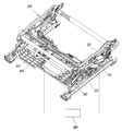
도 1은 본 발명의 일 실시예에 따른 차량용 시트의 높이 조절 장치를 나타낸 도면.
도 2 내지 9는 도 1에 도시된 차량용 시트의 높이 조절 장치를 설명하기 위한 도면.1 is a view showing a height adjustment device for a vehicle seat according to an embodiment of the present invention.
2 to 9 are views for explaining the height adjustment device for the vehicle seat shown in FIG.
이하에서는 첨부된 도면을 참조하여 본 발명의 바람직한 실시 예에 따른 차량용 시트의 높이 조절 장치에 대하여 살펴본다.Hereinafter, a height adjusting device for a vehicle seat according to a preferred embodiment of the present invention will be described with reference to the accompanying drawings.
도 1은 본 발명의 일 실시예에 따른 차량용 시트의 높이 조절 장치를 나타낸 도면이고, 도 2 내지 9는 도 1에 도시된 차량용 시트의 높이 조절 장치를 설명하기 위한 도면이다.1 is a view illustrating a height adjustment device for a vehicle seat according to an embodiment of the present invention, and FIGS. 2 to 9 are views for explaining a height adjustment device for a vehicle seat shown in FIG. 1.
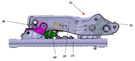
본 발명에 따른 차량용 시트의 높이 조절 장치는 도 1 내지 3에 도시된 바와 같이, 쿠션프레임(20)의 사이드프레임(21)과 시트레일(10)에 회전 가능하게 연결되는 복수의 링크로 구성되고, 복수의 링크가 접힙거나 펼쳐지는 동작에 의해 쿠션프레임(20)이 상하방향으로 이동되도록 하는 하이트링크(30); 쿠션프레임(20)에 설치되고 동작시 전후방향으로 길이가 가변되는 동력전달부(41)가 구비된 구동유닛(40); 및 동력전달부(42)와 하이트링크(30)에 연결되어 구동유닛(40)과 하이트링크(30)과 연동되도록 구성됨으로써, 구동유닛(40)의 동작시 동력전달부(41)의 길이가 증대됨에 따라 하이트링크(30)를 이루는 복수의 링크가 펼쳐지도록 하여 쿠션프레임(20)이 승강되도록 하는 구동기구(50);를 포함한다.Height adjustment device for a vehicle seat according to the present invention is composed of a plurality of links rotatably connected to the
즉, 시트레일(10)에서 구동유닛(40)의 동작시 구동기구(50)가 구동유닛(40)의 동력을 전달받아 하이트링크(30)를 펼지거나 접히도록 하여 쿠션프레임(20)이 상하방향으로 위치가 조절되도록 구성된다.That is, when the
이를 위한 본 발명은 하이트링크(30), 구동유닛(40), 구동기구(50)로 구성되며, 쿠션프레임(20)의 양 사이드프레임(21) 및 시트레일(10)에 한 쌍으로 구성될 수 있다. 여기서, 하이트링크(30)의 경우 복수의 링크로 구성되고 각각의 링크가 쿠션프레임(20)의 사이드프레임(21)과 시트레일(10)에 회전 가능하게 연결되며, 구동유닛(40)의 경우 쿠션프레임(20)에 설치되며 동작시 인입출됨에 따라 길이가 가변되는 동력전달부(41)가 구비된다. 이러한 구동유닛(40)의 동력전달부(41)와 하이트링크(30)는 구동기구(50)에 의해 상호 연동되도록 연결됨으로써, 구동유닛(40)이 동작되어 동력전달부(41)가 인출됨에 따른 길이 증대시 구동기구(50)가 하이트링크(30)를 밀어 복수의 링크가 펼쳐지도록 한다. 이렇게, 하이트링크(30)를 이루는 복수의 링크가 펼쳐지면 상하방향으로 높이가 증대되고, 상하방향으로 높이가 증대된만큼 쿠션프레임(20)이 승강됨으로써, 시트 쿠션의 높낮이를 조절할 수 있다.The present invention for this is composed of a
상술한 본 발명에 대해서 구체적으로 설명하면, 도 2 내지 3에 도시된 바와 같이, 하이트링크(30)는 시트레일(10)에 회전 가능하게 설치되는 제1링크(31)와 사이드프레임(21)에 회전 가능하게 설치되는 제2링크(32)로 구성되고, 제1링크(31)와 제2링크(32)는 서로 회전 가능하게 연결될 수 있다.In detail with respect to the present invention described above, as shown in FIGS. 2 to 3, the
이렇게, 하이트링크(30)는 제1링크(31)와 제2링크(32)로 구성되며, 제1링크(31)와 제2링크(32)의 상대 회전에 의해 펼쳐지거나 접힘 동작될 수 있다. 즉, 제1링크(31)는 시트레일(10)에 설치되고, 제2링크(32)는 시트쿠션에 설치됨에 따라 제1링크(31)와 제2링크(32)는 상하측으로 이격 배치되며, 제1링크(31)와 제2링크(32)가 회전 가능하게 연결됨으로써, 접힙 동작시 상하 높이가 축소되고, 펼쳐짐 동작시 상하 높이가 증대된다.As such, the
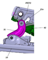
여기서, 사이드프레임(21)에는 호 형상으로 굴곡지게 연장된 가이드홀(21a)이 형성되고, 하이트링크(30)에는 제1링크(31)와 제2링크(32)의 연결 부위에 가이드부(33)가 구비되며, 가이드부(33)가 가이드홀(21a)에 관통 삽입될 수 있다. 이로 인해, 구동유닛(40)이 동작되어 하이트링크(30)의 회전시 하이트링크(30)에 구비된 가이드부(33)가 가이드홀(21a)을 따라 이동됨으로써, 하이트링크(30)를 이루는 제1링크(31)와 제2링크(32)의 펼쳐짐 동작 또는 접힘 동작이 가이드될 수 있다. 또한, 제1링크(31)와 제2링크(32)에 연결된 가이드부(33)가 가이드홀(21a)에 삽입되어 지지됨으로써, 하이트링크(30)의 강건성이 확보되어 전체 내구가 향상되고 안정적인 작동 구조를 이룬다.Here, the
이러한 가이드홀(21a)은 상측에서 하방으로 연장된 후 동력전달부(41)의 진출방향으로 연장되게 형성됨으로써, 가이드부(33)가 가이드홀(21a)을 따라 이동시 제1링크(31)와 제2링크(32)의 펼쳐짐 동작이 안정적으로 가이드되고, 제1링크(31)와 제2링크(32)의 회전 동작이 부드럽게 수행되어 하이트 동작됨에 따른 이질감 발생이 최소화되도록 할 수 있다.The
한편, 도 2에서 볼 수 있듯이, 제1링크(31)는 상방으로 굴곡지게 연장 형성되고, 둘레를 따라 보강비드(31a)가 절곡 형성될 수 있다. 이렇게, 제1링크(31)를 굴곡지게 연장 형성함으로써, 제1링크(31)의 길이를 확보할 수 있고, 하이트링크(30)의 접힘 상태에서 펼쳐짐 동작시 제1링크(31)와 제2링크(32)의 연결 부위의 높이차를 확보할 수 있다. 이로 인해, 시트쿠션의 하이트 동작시 틸트 각도가 증대되도록 할 수 있다.On the other hand, as can be seen in Figure 2, the
또한, 제1링크(31)의 둘레에는 보강비드(31a)가 형성됨으로써, 제1링크(31)의 전체 강성이 증대되며, 보강비드(31a)의 경우 굴곡진 부분에 형성되어 굴곡진 부분의 강성이 국부적으로 증대되도록 할 수 있다.In addition, by forming a
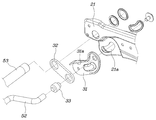
한편, 도 3 내지 4에 도시된 바와 같이, 구동유닛(40)은 쿠션프레임(20)에 고정된 구동모터(42)와, 구동모터(42)의 동작시 인출입되는 동력전달부(41)로 구성되고, 구동모터(42)는 상방을 향해 경사지게 설치되어 동력전달부(41)가 상방으로 경사를 가지고 인출되도록 할 수 있다.Meanwhile, as illustrated in FIGS. 3 to 4, the
여기서, 구동모터(42)는 정역 회전이 가능한 모터로 구성될 수 있으며, 동력전달부(41)는 스크류로 구성되어 구동모터(42)의 회전 동력전달시 스크류가 인출입되도록 구성될 수 있다. 이러한 구동모터(42)는 쿠션프레임(20)에서 상방을 향해 경사지게 설치됨에 따라 동력전달부(41)가 상방으로 경사를 가지고 인출되도록 한다. 이로 인해, 동력전달부(41)에 연결되는 구동기구(50)도 상방으로 이동되는 힘을 전달받고, 구동기구(50)에 연결되는 하이트링크(30)도 경사를 가지고 전방을 향해 상방으로 이동되는 힘을 전달받음으로써, 쿠션프레임(20)이 승강되도록 동작될 수 있다.Here, the
한편, 도 3 내지 5에서 볼 수 있듯이, 구동기구(50)는, 동력전달부(41)의 선단에 회전 가능하게 설치된 회전링크(51); 양단부가 제1링크(31)와 제2링크(32)의 연결 부위에 회전 가능하게 연결되고 회전링크(51)의 선단부에 접촉되도록 형성된 제1연결바(52); 및 양단부가 제2링크(32)와 사이드프레임(21)의 연결 부위에 회전 가능하게 연결되고 회전링크(51)의 말단부에 연결되도록 형성된 제2연결바(53);를 포함한다.On the other hand, as can be seen in Figures 3 to 5, the
즉, 구동기구(50)는 회전링크(51), 제1연결바(52), 제2연결바(53)로 구성되며, 회전링크(51)의 경우 동력전달부(41)의 선단에 회전 가능하게 설치되고, 제1연결바(52)와 제2연결바(53)가 회전링크(51)의 선단부와 말단부에 각각 이격되어 연결됨으로써, 구동유닛(40)의 동작시 동력전달부(41)의 이동에 연동되어 제1연결바(52)와 제2연결바(53)가 연결된 회전링크(51)가 회전될 수 있다.That is, the
여기서, 회전링크(51)의 선단부에는 제1연결바(52)가 삽입되어 걸림 연결되도록 걸림홈(51a)이 형성될 수 있다. 또한, 회전링크(51)의 말단부에는 제2연결바(53)가 회전 가능하게 결합될 수 있다.Here, a locking groove 51a may be formed at the leading end of the
이렇게, 제1연결바(52)와 제2연결바(53)는 회전링크(51)에서 서로 다른 위치에 배치됨으로써, 제1연결바(52)는 제1링크(31)와 제2링크(32)의 연결 부위에 연결되고 제2연결바(53)는 제2링크(32)와 사이드프레임(21)의 연결 부위에 연결될 수 있다. 특히, 도 3 및 도 4를 참조하면, 구동유닛(40)의 동작에 의해 동력전달부(41)의 진출시, 제1링크(31)와 제2링크(32)의 연결 부위는 전방으로 진출되고 제2링크(32)와 사이드프레임(21)의 연결 부위는 상방으로 이동됨에 따라, 제1연결바(52)와 제2연결바(53)의 이동 위치가 상이하다.In this way, the first connecting
따라서, 회전링크(51)의 선단부에 제1연결바(52)가 연결되도록 하고, 말단부에 제2연결바(53)가 연결되도록 함으로써, 구동유닛(40)의 동작시 회전링크(51)가 동력전달부(41)에서 회전됨에 따라 제1연결바(52)와 제2연결바(53)가 하이트링크(30)의 제1링크(31) 및 제2링크(32)를 이동시켜 하이트링크(30)가 펼쳐짐 동작되거나 접힘 동작되도록 할 수 있다.Therefore, the
한편, 제1연결바(52)는 회전링크(51)의 선단부에 접촉되는 중앙단부(52a)와 중앙단부(52a)의 양측단이 굴곡된 후 제1링크(31) 및 제2링크(32)의 연결 부위에 연결되는 연결단부(52b)로 구성될 수 있다. 이로 인해, 제1연결바(52)는 동력전달부(41)에 구비된 회전링크(51)에 원활히 연결될 수 있다. 또한, 구동유닛(40)의 동작시 진출되는 동력전달부(41) 및 회전링크(51)에 의해 중앙단부(52a)가 밀려 이동됨과 동시에, 중앙단부(52a)가 제1링크(31) 및 제2링크(32)의 연결 부위에 연결된 연결단부(52b)를 축으로 회전되면서 구동유닛(40)과 하이트링크(30) 간의 원활한 동작 관계가 수행되도록 할 수 있다.On the other hand, the
한편, 본 발명에서는 상술한 하이트링크(30), 구동유닛(40), 구동기구(50)에 따른 하이트 동작과 더불어 하기에 서술할 구성들을 통해 하이트동작을 수행할 수 있다. On the other hand, in the present invention, in addition to the height operation according to the above-described
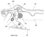
도 6에 도시된 바와 같이, 일단부가 시트레일(10)에 회전 가능하게 설치되고 타단부가 쿠션프레임(20)에 회전 가능하게 연결되며 둘레 일부에 기어치(61)가 형성된 기어링크(60); 및 쿠션프레임(20)에 설치되고 기어링크(60)의 기어치(61)에 기어연결되는 구동기어(71)가 구비되며, 동작시 구동기어(71)의 회전에 의해 기어링크(60)가 시트레일(10)에서 회전됨에 따라 쿠션프레임(20)이 승강되도록 하는 작동유닛(70);을 더 포함할 수 있다.6, one end is rotatably installed on the seat rail (10), the other end is rotatably connected to the cushion frame (20), and a gear link (60) is formed with a gear tooth (61) on a part of the circumference. ; And a
여기서, 기어링크(60)는 섹터 기어 형태로 이루어질 수 있으며, 작동유닛(70)은 구동기어(71)에 회전 동력을 전달하는 작동모터(72)가 더 구성될 수 있다. 이로 인해, 작동모터(72)의 동작시 구동기어(71)가 회전되고, 구동기어(71)와 기어치(61)를 통해 치합된 기어링크(60)가 회전 동력을 전달받아 시트레일(10)에서 회전됨으로써, 쿠션프레임(20)이 밀리거나 당겨져 상하로 이동될 수 있다.Here, the
한편, 기어링크(60)에는 기어치(61)가 연장된 곡률반경을 따라 굴곡지게 연장되는 연장홀(62)이 형성되고, 사이드프레임(21)에는 연장홀(62)에 삽입되는 돌출돌기(22)가 형성될 수 있다. 이로 인해, 작동유닛(70)의 동작시 돌출돌기(22)가 삽입된 기어링크(60)의 연장홀(62)을 따라 기어링크(60)가 회전됨으로써, 쿠션프레임(20)이 가이드되어 원활히 승강동작될 수 있다. 또한, 기어링크(60)에 형성된 연장홀(62)에 돌출돌기(22)가 삽입되어 지지됨으로써, 강건성이 확보되어 전체 내구가 향상되고 안정적인 작동 구조를 이룰 수 있다.On the other hand, the
한편, 본 발명은 도 1 및 도 7에서 볼 수 있듯이, 하이트링크(30), 구동유닛(40), 구동기구(50)의 구성은 시트레일(10) 및 쿠션프레임(20)의 전방부에 설치되고, 기어링크(60), 작동유닛(70)의 구성은 시트레일(10) 및 쿠션프레임(20)의 후방부에 설치될 수 있다. 즉, 하이트링크(30), 구동유닛(40), 구동기구(50)의 구성은 상대적으로 높낮이 조절이 길게 확보됨에 따라 시트쿠션의 전방부의 틸팅 각도를 크게 확보할 수 있고, 기어링크(60), 작동유닛(70)의 구성은 상대적으로 높은 내구강성이 확보됨에 따라 탑승자의 하중을 견고히 지지할 수 있도록 한다. 또한, 구동유닛(40)과 작동유닛(70)의 선택적인 제어 또는 동시 제어를 통해 시트쿠션의 틸팅 각도를 다양하게 구현 가능하다.On the other hand, the present invention, as can be seen in Figures 1 and 7, the
하기에는, 상술한 본 발명의 작동에 대해서 구체적으로 설명한다.In the following, the operation of the present invention described above will be specifically described.
시트쿠션의 초기 상태에서는, 도 3에 도시된 바와 같이, 구동유닛(40)의 동력전달부(41)가 인입되고, 하이트링크(30)의 제1링크(31)와 제2링크(32)가 접혀진 상태를 이룬다. 이에 따라, 제1링크(31)와 제2링크(32)의 연결 부위에 구비된 가이드부(33)는 가이드홀(21a)의 후방에 위치된다.In the initial state of the seat cushion, as shown in FIG. 3, the
여기서, 도 4에 도시된 바와 같이, 구동유닛(40)의 동력전달부(41)가 인출되면, 동력전달부(41)에 장착된 회전링크(51)가 제1연결바(52)와 제2연결바(53)를 전방 상측으로 밀어주게 된다. 이때, 회전링크(51)가 동력전달부(41)에서 회전됨과 동시에 가이드부(33)가 가이드홀(21a)을 따라 전방으로 이동되어 제1링크(31)가 수직한 방향으로 회전되고, 제2연결바(53)와 함께 제2링크(32)도 수직한 방향으로 회전됨으로써, 쿠션프레임(20)이 승강된다. 이를 위해, 가이드홀(21a)이 연장되는 곡률반경, 제1링크(31)의 형상에 따른 곡률반경, 제1연결바(52)의 중앙단부(52a) 및 제2연결바(53)가 회전되는 곡률 반경이 유사 곡률반경을 가질 수 있으며, 제1링크(31)만 반대로 회전되어 쿠션프레임(20)의 승강동작이 이루어진다.Here, as shown in FIG. 4, when the
한편, 기어링크(60), 작동유닛(70)은 시트 쿠션의 하이트 동작 여부에 따라 작동유닛(70)의 동작되어 구동기어(71)가 회전되고, 구동기어(71)에 기어치(61)를 통해 치합된 기어링크(60)가 회전 동력을 전달받아 시트레일(10)에서 회전됨으로서, 쿠션프레임(20)이 밀리거나 당겨져 상하로 이동되도록 할 수 있다.Meanwhile, the
상술한 구동유닛(40)과 작동유닛(70)은 제어기의 제어에 의해 동작될 수 있으며, 구동유닛(40)과 작동유닛(70)의 동시 제어 또는 선택적인 제어를 수행할 수 있다.The above-described
상세하게, 구동유닛 및 작동유닛을 제어하는 제어기;를 더 포함하고, 제어기는 구동유닛 및 작동유닛을 제어하여 쿠션프레임의 높이 및 각도를 조절함으로써, 착좌한 탑승자의 힙포인트 위치를 변화시킬 수 있다.In detail, further comprising a controller for controlling the driving unit and the operating unit; the controller may control the driving unit and the operating unit to adjust the height and angle of the cushion frame, thereby changing the hippoint position of the seated occupant. .
여기서, 탑승자의 힙포인트는 탑승자가 시트에 착좌한 상태에서 탑승자의 엉덩이 위치가 되는 것으로, 본 발명은 구동유닛(40) 및 작동유닛(70)의 동작시 상술한 하이트링크(30) 및 기어링크(60)의 회전에 의해 쿠션프레임(20)의 높이 및 각도가 조절되어 탑승자의 힙포인트 위치가 변화됨으로써, 쿠션프레임(20)의 높이 및 각도에 따른 다양한 모드가 구현될 수 있다.Here, the hippoint of the occupant is to be the position of the hip of the occupant in a state where the occupant is seated on the seat, and the present invention is the above-described
즉, 제어기(80)가 구동유닛(40)과 작동유닛(70)을 제어하여 쿠션프레임(20)의 높이 조절시, 구동유닛(40)의 동작에 의해 하이트링크(30)를 이루는 복수의 링크가 회전되어 펼쳐지고, 작동유닛(70)의 동작에 의해 기어링크(60)가 회전됨으로써, 힙포인트 위치가 전방으로 곡선 궤적을 그리며 변화될 수 있다.That is, when the
도 7에 도시된 바와 같이, 구동유닛(40)과 작동유닛(70)이 미동작되면, 하이트링크(30)의 제1링크(31)와 제2링크(32)가 접혀지고, 기어링크(60)가 뉘어진 상태를 이룬다. 이에 따라, 초기 힙포인트(P1)는 도 7에 도시된 바와 같이 위치된다. 이러한 상태에서, 제어기(80)의 제어에 의해, 구동유닛(40)이 동작되면 하이트링크(30)가 회전되어 펼쳐지고, 작동유닛(70)이 동작되면 기어링크(60)가 회전된다. 이때, 쿠션프레임(20)은 도 8에 도시된 바와 같이, 상측 전방으로 이동되고, 그에 따라 힙포인트는 초기 힙포인트(P1)에서 하이트 힙포인트(P2)로 이동된다. 이와 더불어, 힙포인트의 위치는 전방으로 곡선 궤적을 그리면서 변화됨으로써, 쿠션프레임(20)이 시트백프레임과 간섭이 방지되고, 탑승자의 착좌 자세에 이질감이 발생되지 않는다. As shown in FIG. 7, when the driving
한편, 제어기(80)가 구동유닛(40)을 제어하여 쿠션프레임(20)의 각도 조절시, 구동유닛(40)의 동작에 의해 하이트링크(30)를 이루는 복수의 링크가 회전되어 펼쳐짐으로써, 힙포인트의 위치가 후방으로 곡선 궤적을 그리며 변화될 수 있다.On the other hand, when the
도 9에 도시된 바와 같이, 구동유닛(40)이 동작되어 쿠션프레임(20)의 높이 조절을 수행하면, 링크(30)가 회전되어 펼쳐짐에 따라 쿠션프레임의 전방부가 상승된다. 이때, 도 9에 도시된 바와 같이 힙포인트는 초기 힙포인트(P1)에서 릴리즈 힙포인트(P3)로 이동되고, 힙포인트의 위치는 후방으로 곡선 궤적을 그리면서 변화됨으로써, 탑승자의 착좌 자세 변화에 따른 이질감이 최소화되어 착좌감이 상승된다.9, when the driving
이에 따라, 본 발명에서는 도 7에 도시된 바와 같이 초기 상태 및 시트쿠션의 높이를 낮게 배치되도록 조절하는 초기모드를 수행하거나, 도 8에 도시된 바와 같이 구동유닛(40)과 작동유닛(70)이 동작되어 시트쿠션의 높이가 높게 배치되도록 조절하는 하이트모드를 수행할 수 있다. 또한, 도 9에 도시된 바와 같이 구동유닛(40)만 동작되도록 하여 시트쿠션의 앞부분이 들림에 따라 탑승자의 누운자세에 부합되는 릴렉스모드를 수행할 수 있다.Accordingly, in the present invention, an initial mode for adjusting the initial state and the height of the seat cushion to be arranged as shown in FIG. 7 is performed, or the driving
이러한 도 7 내지 9에 도시된 각종모드 외에 구동유닛(40)과 작동유닛(70)의 선택적인 동작을 통해, 탑승자의 자세에 부합되는 시트쿠션의 높이 및 각도가 다양하게 조절될 수 있다.In addition to the various modes shown in FIGS. 7 to 9, through the optional operation of the driving
상술한 바와 같은 구조로 이루어진 차량용 시트의 높이 조절 장치는 시트쿠션의 하이트 구동시 시트쿠션의 틸팅 각도가 확보되고, 시트쿠션의 전방부와 후방부가 개별적으로 하이트 동작됨으로써, 탑승자의 다양한 자세에 대응하여 시트쿠션의 각도가 조절됨에 따라 편의성이 향상된다. 또한, 링크 연결 구조가 견고히 구성되어 자체 내구성이 향상된다.The height adjustment device for a vehicle seat having the structure as described above secures the tilting angle of the seat cushion when the seat cushion is height-driven, and is individually operated by hitting the front and rear portions of the seat cushion in response to various postures of the occupant. Convenience is improved as the angle of the seat cushion is adjusted. In addition, the link connection structure is solidly constructed to improve its durability.
본 발명은 특정한 실시예에 관련하여 도시하고 설명하였지만, 이하의 특허청구범위에 의해 제공되는 본 발명의 기술적 사상을 벗어나지 않는 한도 내에서, 본 발명이 다양하게 개량 및 변화될 수 있다는 것은 당 업계에서 통상의 지식을 가진 자에게 있어서 자명할 것이다.Although the present invention has been illustrated and described in relation to specific embodiments, it is understood in the art that the present invention can be variously improved and changed within the limits that do not depart from the technical spirit of the present invention provided by the following claims. It will be obvious to those of ordinary skill.
10:시트레일 20:쿠션프레임
21:사이드프레임 21a:가이드홀
22:돌출돌기 30:하이트링크
31:제1링크 31a:보강비드
32:제2링크 33:가이드부
40:구동유닛 41:동력전달부
42:구동모터 50:구동기구
51:회전링크 51a:걸림홈
52:제1연결바 52a:중앙단부
52b:연결단부 53:제2연결바
60:기어링크 61:기어치
62:연장홀 70:작동유닛
71:구동기어 72:작동모터
80:제어기10: seat rail 20: cushion frame
21:
22: protrusion 30: height link
31:
32: second link 33: guide section
40: drive unit 41: power transmission unit
42: drive motor 50: drive mechanism
51: rotating link 51a: jamming groove
52:
52b: connection end 53: second connection bar
60: gear link 61: gear
62: extension hole 70: operating unit
71: drive gear 72: operating motor
80: controller
Claims (15)
쿠션프레임의 사이드프레임과 시트레일에 회전 가능하게 연결되는 복수의 링크로 구성되고, 복수의 링크가 접힙거나 펼쳐지는 동작에 의해 쿠션프레임이 상하방향으로 이동되도록 하는 하이트링크;
쿠션프레임에 설치되고 동작시 전후방향으로 길이가 가변되는 동력전달부가 구비된 구동유닛; 및
동력전달부와 하이트링크에 연결되어 구동유닛과 하이트링크과 연동되도록 구성됨으로써, 구동유닛의 동작시 동력전달부의 길이가 증대됨에 따라 하이트링크를 이루는 복수의 링크가 펼쳐지도록 하여 쿠션프레임이 승강되도록 하는 구동기구;를 포함하는 차량용 시트의 높이 조절 장치.In the seat rail height adjustment device for a vehicle seat is composed of a cushion frame that is adjusted in the vertical direction in the seat rail,
It consists of a plurality of links that are rotatably connected to the side frame and seat rail of the cushion frame, the height link to move the cushion frame in the vertical direction by the folding or unfolding operation of the plurality of links;
A drive unit installed in the cushion frame and provided with a power transmission unit having a variable length in the front-rear direction during operation; And
It is connected to the power transmission unit and the height link, and is configured to interlock with the driving unit and the height link, so that a plurality of links constituting the height link are opened and the cushion frame is raised and lowered as the length of the power transmission unit increases when the driving unit is operated. Mechanism; height adjustment device for a vehicle seat comprising a.
하이트링크는 시트레일에 회전 가능하게 설치되는 제1링크와 사이드프레임에 회전 가능하게 설치되는 제2링크로 구성되고, 제1링크와 제2링크는 서로 회전 가능하게 연결된 것을 특징으로 하는 차량용 시트의 높이 조절 장치.The method according to claim 1,
The height link consists of a first link rotatably installed on the seat rail and a second link rotatably installed on the side frame, and the first link and the second link are rotatably connected to each other. Height adjustment device.
사이드프레임에는 호 형상으로 굴곡지게 연장된 가이드홀이 형성되고,
하이트링크에는 제1링크와 제2링크의 연결 부위에 가이드부가 구비되며, 가이드부가 가이드홀에 관통 삽입된 것을 특징으로 하는 차량용 시트의 높이 조절 장치.The method according to claim 2,
The side frame is formed with a guide hole extending in an arc shape,
Height link is a height adjustment device for a vehicle seat, characterized in that the guide portion is provided at the connection portion of the first link and the second link, the guide portion is inserted through the guide hole.
가이드홀은 상측에서 하방으로 연장된 후 동력전달부의 진출방향으로 연장되게 형성된 것을 특징으로 하는 차량용 시트의 높이 조절 장치.The method according to claim 3,
The guide hole is a height adjustment device for a vehicle seat, characterized in that it is formed to extend downward from the upper side and then extend in the forward direction of the power transmission unit.
제1링크는 상방으로 굴곡지게 연장 형성되고, 둘레를 따라 보강비드가 절곡 형성된 것을 특징으로 하는 차량용 시트의 높이 조절 장치.The method according to claim 2,
The first link is formed to extend upward to bend, and a height adjusting device for a vehicle seat, characterized in that the reinforcing beads are bent along the circumference.
구동유닛은 쿠션프레임에 고정된 구동모터와, 구동모터의 동작시 인출입되는 동력전달부로 구성되고,
구동모터는 상방을 향해 경사지게 설치되어 동력전달부가 상방으로 경사를 가지고 인출되는 것을 특징으로 하는 차량용 시트의 높이 조절 장치.The method according to claim 1,
The driving unit is composed of a driving motor fixed to the cushion frame and a power transmission unit that is drawn in and out during operation of the driving motor.
The driving motor is installed obliquely upward, and the power transmission unit is height-adjusted for a vehicle seat, characterized in that it is drawn out with an inclination upward.
구동기구는,
동력전달부의 선단에 회전 가능하게 설치된 회전링크;
양단부가 제1링크와 제2링크의 연결 부위에 회전 가능하게 연결되고 회전링크의 선단부에 접촉되도록 형성된 제1연결바; 및
양단부가 제2링크와 사이드프레임의 연결 부위에 회전 가능하게 연결되고 회전링크의 말단부에 연결되도록 형성된 제2연결바;를 포함하는 것을 특징으로 하는 차량용 시트의 높이 조절 장치.The method according to claim 2,
The driving mechanism,
A rotating link rotatably installed at the front end of the power transmission unit;
A first connection bar rotatably connected to both ends of the first link and the second link and contacting the front end of the rotation link; And
A height adjustment device for a vehicle seat, comprising: a second connection bar formed to be rotatably connected to both ends of the second link and the connecting portion of the side frame and connected to the distal end of the rotating link.
회전링크의 선단부에는 제1연결바가 삽입되어 걸림 연결되도록 걸림홈이 형성된 것을 특징으로 하는 차량용 시트의 높이 조절 장치.The method according to claim 7,
Height adjustment device for a vehicle seat, characterized in that the first link bar is inserted into the front end of the rotary link so that a locking groove is formed to be engaged.
제1연결바는 회전링크의 선단부에 접촉되는 중앙단부와 중앙단부의 양측단이 굴곡된 후 제1링크 및 제2링크의 연결 부위에 연결되는 연결단부로 구성된 것을 특징으로 하는 차량용 시트의 높이 조절 장치.The method according to claim 7,
The first connection bar is height-adjusting the height of the vehicle seat, characterized in that it consists of a connecting end connected to the connecting portion of the first link and the second link after the both ends of the central end and the central end contacting the leading end of the rotating link are bent. Device.
일단부가 시트레일에 회전 가능하게 설치되고 타단부가 쿠션프레임에 회전 가능하게 연결되며 둘레 일부에 기어치가 형성된 기어링크; 및
쿠션프레임에 설치되고 기어링크의 기어치에 기어연결되는 구동기어가 구비되며, 동작시 구동기어의 회전에 의해 기어링크가 시트레일에서 회전됨에 따라 쿠션프레임이 승강되도록 하는 작동유닛;을 더 포함하는 것을 특징으로 하는 차량용 시트의 높이 조절 장치.The method according to claim 1,
A gear link having one end rotatably installed on the seat rail, the other end rotatably connected to the cushion frame, and gear teeth formed on a part of the circumference; And
It is installed on the cushion frame and is provided with a drive gear that is gear-connected to the gear teeth of the gear link, and when the gear link is rotated on the seat rail by the rotation of the drive gear during operation, an operating unit that allows the cushion frame to be elevated; Height adjustment device for a vehicle seat, characterized in that.
기어링크에는 기어치가 연장된 곡률반경을 따라 굴곡지게 연장되는 연장홀이 형성되고,
사이드프레임에는 연장홀에 삽입되는 돌출돌기가 형성된 것을 특징으로 하는 차량용 시트의 높이 조절 장치.The method according to claim 10,
The gear link is formed with an extension hole extending bent along a radius of curvature with an extended gear tooth,
Height adjustment device for the vehicle seat, characterized in that the protruding projection inserted into the extension frame is formed in the side frame.
하이트링크, 구동유닛, 구동기구의 구성은 시트레일 및 쿠션프레임의 전방부에 설치되고,
기어링크, 작동유닛의 구성은 시트레일 및 쿠션프레임의 후방부에 설치된 것을 특징으로 하는 차량용 시트의 높이 조절 장치.The method according to claim 10,
The composition of the height link, the driving unit and the driving mechanism is installed in the front part of the seat rail and cushion frame,
Gear link, the configuration of the operating unit seat rail and the height adjustment device for the vehicle seat, characterized in that installed on the rear of the cushion frame.
구동유닛 및 작동유닛을 제어하는 제어기;를 더 포함하고,
제어기는 구동유닛 및 작동유닛을 제어하여 쿠션프레임의 높이 및 각도를 조절함으로써, 착좌한 탑승자의 힙포인트 위치를 변화시키는 것을 특징으로 하는 차량용 시트의 높이 조절 장치.The method according to claim 10,
Further comprising a controller for controlling the driving unit and the operating unit,
The controller controls the driving unit and the operating unit to adjust the height and angle of the cushion frame, thereby changing the position of the seated occupant's hip point.
제어기가 구동유닛과 작동유닛을 제어하여 쿠션프레임의 높이 조절시, 구동유닛의 동작에 의해 하이트링크를 이루는 복수의 링크가 회전되면서 펼쳐지고, 작동유닛의 동작에 의해 기어링크가 회전됨으로써, 힙포인트 위치가 전방으로 곡선 궤적을 그리며 변화되는 것을 특징으로 하는 차량용 시트의 높이 조절 장치.The method according to claim 13,
When the controller controls the drive unit and the operation unit and adjusts the height of the cushion frame, a plurality of links forming a high link are rotated by the operation of the drive unit, and the gear link is rotated by the operation of the operation unit, thereby positioning the hippoint. Height adjustment device for a vehicle seat, characterized in that is changed while drawing a curved trajectory forward.
제어기가 구동유닛을 제어하여 쿠션프레임의 각도 조절시, 구동유닛의 동작에 의해 하이트링크를 이루는 복수의 링크가 회전되어 펼쳐짐으로써, 힙포인트의 위치가 후방으로 곡선 궤적을 그리며 변화되는 것을 특징으로 하는 차량용 시트의 높이 조절 장치.The method according to claim 13,
When the controller controls the drive unit and adjusts the angle of the cushion frame, a plurality of links forming a high link are rotated and unfolded by the operation of the drive unit, so that the position of the hip point is changed while drawing a curved trajectory to the rear. Height adjustment device for car seat.
Priority Applications (4)
| Application Number | Priority Date | Filing Date | Title |
|---|---|---|---|
| KR1020180147147A KR102602914B1 (en) | 2018-11-26 | 2018-11-26 | Seat height adjust apparatus for vehicle seat |
| US16/356,563 US10744909B2 (en) | 2018-11-26 | 2019-03-18 | Height adjustment apparatus of vehicle seat |
| DE102019203863.8A DE102019203863B4 (en) | 2018-11-26 | 2019-03-21 | Height adjustment device for a vehicle seat |
| CN201910234647.3A CN111216606B (en) | 2018-11-26 | 2019-03-26 | Height adjusting device for vehicle seat |
Applications Claiming Priority (1)
| Application Number | Priority Date | Filing Date | Title |
|---|---|---|---|
| KR1020180147147A KR102602914B1 (en) | 2018-11-26 | 2018-11-26 | Seat height adjust apparatus for vehicle seat |
Publications (2)
| Publication Number | Publication Date |
|---|---|
| KR20200062425A true KR20200062425A (en) | 2020-06-04 |
| KR102602914B1 KR102602914B1 (en) | 2023-11-16 |
Family
ID=70546069
Family Applications (1)
| Application Number | Title | Priority Date | Filing Date |
|---|---|---|---|
| KR1020180147147A KR102602914B1 (en) | 2018-11-26 | 2018-11-26 | Seat height adjust apparatus for vehicle seat |
Country Status (4)
| Country | Link |
|---|---|
| US (1) | US10744909B2 (en) |
| KR (1) | KR102602914B1 (en) |
| CN (1) | CN111216606B (en) |
| DE (1) | DE102019203863B4 (en) |
Cited By (3)
| Publication number | Priority date | Publication date | Assignee | Title |
|---|---|---|---|---|
| CN113352961A (en) * | 2021-07-28 | 2021-09-07 | 重庆延锋安道拓汽车部件系统有限公司 | Zero-gravity seat frame adjusting system |
| CN114394037A (en) * | 2022-02-11 | 2022-04-26 | 诺博汽车系统有限公司 | Framework of adjustable seat and adjustable seat |
| WO2023101382A1 (en) * | 2021-12-01 | 2023-06-08 | 주식회사 포스코 | Seat frame |
Families Citing this family (5)
| Publication number | Priority date | Publication date | Assignee | Title |
|---|---|---|---|---|
| KR102218451B1 (en) * | 2019-08-09 | 2021-02-19 | 주식회사 포스코 | Seat frame |
| CN114194088B (en) * | 2020-09-02 | 2023-06-06 | 诺创汽车科技(上海)有限公司 | Chair framework |
| US11795631B2 (en) | 2021-06-22 | 2023-10-24 | Caterpillar Paving Products Inc. | Linkage system for screed extension |
| CN113844342B (en) * | 2021-11-09 | 2023-03-24 | 麦格纳座椅研发(重庆)有限公司 | Car seat based on inclination adjustment mechanism |
| CN114394043A (en) * | 2022-02-11 | 2022-04-26 | 诺博汽车系统有限公司 | Framework of adjustable seat and adjustable seat |
Citations (4)
| Publication number | Priority date | Publication date | Assignee | Title |
|---|---|---|---|---|
| US6021990A (en) * | 1998-07-28 | 2000-02-08 | Meritor Automotive Canada, Inc. | Integrated lead screw drive for seat adjuster |
| JP2009202844A (en) | 2008-02-29 | 2009-09-10 | Aisin Seiki Co Ltd | Seat lifter device |
| US20090230752A1 (en) * | 2008-03-14 | 2009-09-17 | Lear Corporation | Pivot joint assembly for a vehicle seat |
| US20180001793A1 (en) * | 2016-06-29 | 2018-01-04 | GM Global Technology Operations LLC | Seat frame for a height-adjustable and tiltable seat pan |
Family Cites Families (36)
| Publication number | Priority date | Publication date | Assignee | Title |
|---|---|---|---|---|
| BE790401A (en) | 1971-10-22 | 1973-02-15 | Isringhausen Geb | ADJUSTABLE LEVEL AND TILT VEHICLE SEAT |
| GB2018583A (en) * | 1978-01-27 | 1979-10-24 | Ti Cox Ltd | Rise and fall mechanism for a vehicle seat |
| FR2692529B1 (en) | 1992-06-18 | 1994-09-16 | Faure Bertrand Automobile | Improvements to vehicle seats with multiple settings. |
| FR2771688B1 (en) * | 1997-11-28 | 2000-01-28 | Faure Bertrand Equipements Sa | SEAT HAVING AN INTEGRATED SAFETY BELT |
| DE19914163A1 (en) * | 1999-03-29 | 2000-10-05 | Bayerische Motoren Werke Ag | Seat for motor vehicle has backrest fastened via height-adjusting unit to longitudinally adjustable seat rail |
| DE10113153C1 (en) * | 2001-03-14 | 2002-04-25 | Brose Fahrzeugteile | Underframe, for automobile passenger seat, has transverse axis between guide elements for movement of seat support relative to seat frame coupled to height and inclination adjustment drives |
| KR20030049786A (en) | 2001-12-17 | 2003-06-25 | 현대자동차주식회사 | Integrated Memory System for automobile |
| JP2004306923A (en) | 2003-04-10 | 2004-11-04 | Shigeru Co Ltd | Vehicle seat |
| JP4548010B2 (en) | 2004-06-17 | 2010-09-22 | マツダ株式会社 | Car movable floor equipment |
| US20090302158A1 (en) | 2005-12-23 | 2009-12-10 | British Airways Plc | Aircraft Passenger Seat |
| FR2901196B1 (en) | 2006-05-16 | 2009-02-27 | Renault Sas | MOTOR VEHICLE HAVING A SEAT EQUIPPED WITH INCLINATION MEANS |
| JP4883441B2 (en) * | 2006-05-19 | 2012-02-22 | テイ・エス テック株式会社 | Automotive seat height adjustment device |
| FR2911817B1 (en) | 2007-01-31 | 2009-09-11 | Heuliez Sa | DEVICE FOR MANEUVERING A VEHICLE SEAT. |
| JP2008195301A (en) * | 2007-02-14 | 2008-08-28 | Delta Tooling Co Ltd | Seat |
| JP5159384B2 (en) | 2008-03-21 | 2013-03-06 | シロキ工業株式会社 | Seat seat with manual height adjustment mechanism |
| JP5486349B2 (en) | 2010-03-01 | 2014-05-07 | テイ・エス テック株式会社 | Vehicle seat |
| JP5218506B2 (en) * | 2010-09-17 | 2013-06-26 | アイシン精機株式会社 | Seat lifter device |
| CN103189231B (en) | 2010-10-01 | 2015-07-15 | 丰田车体株式会社 | Vehicle seat |
| JP5866159B2 (en) | 2011-08-10 | 2016-02-17 | テイ・エス テック株式会社 | Vehicle seat |
| KR101813105B1 (en) * | 2011-09-23 | 2018-01-02 | 주식회사 다스 | Seat for automobile having a integrated height and tilt adjusting mechanism for a seat cushion |
| DE102011122275A1 (en) * | 2011-12-23 | 2013-06-27 | Gm Global Technology Operations, Llc | Adjusting device for adjusting seat height of motor car, has first gear and/or first toothed arc that are formed as separate sheet from pivotable arm by operation of second gear and/or second toothed arc of pivotable arm |
| DE102013101540B4 (en) * | 2013-02-15 | 2021-10-07 | Faurecia Autositze Gmbh | Vehicle seat, in particular for a motor vehicle |
| JP6237468B2 (en) | 2013-06-10 | 2017-11-29 | トヨタ紡織株式会社 | Vehicle seat |
| JP6168970B2 (en) | 2013-06-16 | 2017-07-26 | 株式会社デルタツーリング | Power seat slide device and vehicle seat |
| KR101526979B1 (en) | 2013-12-13 | 2015-06-09 | 현대자동차주식회사 | Shield cover of seat for vehicle |
| KR101557098B1 (en) | 2014-03-21 | 2015-10-15 | 주식회사 한영아이피 | An electric chair for washing hair |
| JP2017019441A (en) | 2015-07-13 | 2017-01-26 | トヨタ自動車株式会社 | Vehicle seat |
| KR101827130B1 (en) | 2016-07-06 | 2018-02-07 | 현대자동차주식회사 | Height adjusting apparatus of vehicle seat |
| JP6587749B2 (en) * | 2016-07-28 | 2019-10-09 | 株式会社タチエス | Vehicle seat |
| FR3058943B1 (en) * | 2016-11-21 | 2018-11-23 | Peugeot Citroen Automobiles Sa | SUSPENSION OF A VEHICLE SEAT AND ADJUSTMENT OF THE POSITION OF THE SEAT |
| DE102016015170A1 (en) * | 2016-12-20 | 2018-06-21 | GM Global Technology Operations LLC (n. d. Ges. d. Staates Delaware) | Vehicle seat seat adjustment |
| JP6662360B2 (en) * | 2017-08-23 | 2020-03-11 | マツダ株式会社 | Vehicle seat and design method thereof |
| US10442322B2 (en) * | 2017-11-17 | 2019-10-15 | Brose Fahrzeugteile Gmbh & Co. Kommanditgesellschaft | Easy-entry vehicle seat |
| US10358052B1 (en) * | 2018-03-16 | 2019-07-23 | Adient Engineering and IP GmbH | Seat lifter structure and vehicle seat equipped with the same |
| JP7004271B2 (en) * | 2018-04-10 | 2022-02-04 | 日本発條株式会社 | Vehicle seat |
| US10661684B2 (en) * | 2018-07-03 | 2020-05-26 | Sears Manufacturing Co. | Seat height and tilt adjustment mechanism |
-
2018
- 2018-11-26 KR KR1020180147147A patent/KR102602914B1/en active IP Right Grant
-
2019
- 2019-03-18 US US16/356,563 patent/US10744909B2/en active Active
- 2019-03-21 DE DE102019203863.8A patent/DE102019203863B4/en active Active
- 2019-03-26 CN CN201910234647.3A patent/CN111216606B/en active Active
Patent Citations (4)
| Publication number | Priority date | Publication date | Assignee | Title |
|---|---|---|---|---|
| US6021990A (en) * | 1998-07-28 | 2000-02-08 | Meritor Automotive Canada, Inc. | Integrated lead screw drive for seat adjuster |
| JP2009202844A (en) | 2008-02-29 | 2009-09-10 | Aisin Seiki Co Ltd | Seat lifter device |
| US20090230752A1 (en) * | 2008-03-14 | 2009-09-17 | Lear Corporation | Pivot joint assembly for a vehicle seat |
| US20180001793A1 (en) * | 2016-06-29 | 2018-01-04 | GM Global Technology Operations LLC | Seat frame for a height-adjustable and tiltable seat pan |
Cited By (3)
| Publication number | Priority date | Publication date | Assignee | Title |
|---|---|---|---|---|
| CN113352961A (en) * | 2021-07-28 | 2021-09-07 | 重庆延锋安道拓汽车部件系统有限公司 | Zero-gravity seat frame adjusting system |
| WO2023101382A1 (en) * | 2021-12-01 | 2023-06-08 | 주식회사 포스코 | Seat frame |
| CN114394037A (en) * | 2022-02-11 | 2022-04-26 | 诺博汽车系统有限公司 | Framework of adjustable seat and adjustable seat |
Also Published As
| Publication number | Publication date |
|---|---|
| CN111216606A (en) | 2020-06-02 |
| CN111216606B (en) | 2023-05-26 |
| KR102602914B1 (en) | 2023-11-16 |
| US20200164772A1 (en) | 2020-05-28 |
| DE102019203863A1 (en) | 2020-05-28 |
| US10744909B2 (en) | 2020-08-18 |
| DE102019203863B4 (en) | 2023-11-02 |
Similar Documents
| Publication | Publication Date | Title |
|---|---|---|
| KR20200062425A (en) | Seat height adjust apparatus for vehicle seat | |
| JP5043385B2 (en) | Automotive seat device | |
| JP5087974B2 (en) | Vehicle seat | |
| EP1924463B1 (en) | Seat assembly having a seat cushion rocker mechanism | |
| JP5087975B2 (en) | Vehicle seat | |
| JP6662360B2 (en) | Vehicle seat and design method thereof | |
| KR20210031037A (en) | Rear seat for vehicle | |
| KR20230076902A (en) | Device for adjusting position of armrest having control panel for vehicle | |
| JP4923905B2 (en) | Sheet device | |
| CN109789826B (en) | Leg support with anti-twisting function | |
| KR20220045861A (en) | Seat adjust apparatus for vehicle seat | |
| JP4534831B2 (en) | Automotive seat position adjustment device | |
| CA3038553C (en) | Diving cushion for a reversible seat | |
| JP5056125B2 (en) | Vehicle seat | |
| KR101785277B1 (en) | Apparatus for moving seat cushion of vehicle | |
| US20220297578A1 (en) | Railless variable seatback type rear seat | |
| JP2006213103A (en) | Seating posture adjusting device of automobile | |
| JP2008149858A (en) | Seat device for vehicle | |
| JP2010095178A (en) | Vehicular seat | |
| KR20210082813A (en) | Efficient Car Seat Headrest Adjuster | |
| EP3768551B1 (en) | Retractable bolsters for a reversible seat | |
| JP2008049846A (en) | Automotive seat device | |
| US20230398913A1 (en) | Seat assembly with zero-gravity position | |
| JP5018001B2 (en) | Vehicle seat device | |
| KR102457330B1 (en) | Seat chusion extension device |
Legal Events
| Date | Code | Title | Description |
|---|---|---|---|
| A201 | Request for examination | ||
| E902 | Notification of reason for refusal | ||
| E701 | Decision to grant or registration of patent right | ||
| GRNT | Written decision to grant |