KR20190044580A - Chair structure and chair - Google Patents
Chair structure and chair Download PDFInfo
- Publication number
- KR20190044580A KR20190044580A KR1020187008934A KR20187008934A KR20190044580A KR 20190044580 A KR20190044580 A KR 20190044580A KR 1020187008934 A KR1020187008934 A KR 1020187008934A KR 20187008934 A KR20187008934 A KR 20187008934A KR 20190044580 A KR20190044580 A KR 20190044580A
- Authority
- KR
- South Korea
- Prior art keywords
- chair
- unit
- support
- seat
- connecting rod
- Prior art date
Links
Images


Classifications
-
- A—HUMAN NECESSITIES
- A47—FURNITURE; DOMESTIC ARTICLES OR APPLIANCES; COFFEE MILLS; SPICE MILLS; SUCTION CLEANERS IN GENERAL
- A47C—CHAIRS; SOFAS; BEDS
- A47C1/00—Chairs adapted for special purposes
- A47C1/02—Reclining or easy chairs
- A47C1/031—Reclining or easy chairs having coupled concurrently adjustable supporting parts
- A47C1/032—Reclining or easy chairs having coupled concurrently adjustable supporting parts the parts being movably-coupled seat and back-rest
- A47C1/03261—Reclining or easy chairs having coupled concurrently adjustable supporting parts the parts being movably-coupled seat and back-rest characterised by elastic means
- A47C1/03272—Reclining or easy chairs having coupled concurrently adjustable supporting parts the parts being movably-coupled seat and back-rest characterised by elastic means with coil springs
-
- A—HUMAN NECESSITIES
- A47—FURNITURE; DOMESTIC ARTICLES OR APPLIANCES; COFFEE MILLS; SPICE MILLS; SUCTION CLEANERS IN GENERAL
- A47C—CHAIRS; SOFAS; BEDS
- A47C7/00—Parts, details, or accessories of chairs or stools
- A47C7/02—Seat parts
-
- A—HUMAN NECESSITIES
- A47—FURNITURE; DOMESTIC ARTICLES OR APPLIANCES; COFFEE MILLS; SPICE MILLS; SUCTION CLEANERS IN GENERAL
- A47C—CHAIRS; SOFAS; BEDS
- A47C1/00—Chairs adapted for special purposes
- A47C1/02—Reclining or easy chairs
- A47C1/031—Reclining or easy chairs having coupled concurrently adjustable supporting parts
- A47C1/032—Reclining or easy chairs having coupled concurrently adjustable supporting parts the parts being movably-coupled seat and back-rest
- A47C1/03255—Reclining or easy chairs having coupled concurrently adjustable supporting parts the parts being movably-coupled seat and back-rest with a central column, e.g. rocking office chairs
-
- A—HUMAN NECESSITIES
- A47—FURNITURE; DOMESTIC ARTICLES OR APPLIANCES; COFFEE MILLS; SPICE MILLS; SUCTION CLEANERS IN GENERAL
- A47C—CHAIRS; SOFAS; BEDS
- A47C1/00—Chairs adapted for special purposes
- A47C1/02—Reclining or easy chairs
- A47C1/031—Reclining or easy chairs having coupled concurrently adjustable supporting parts
- A47C1/032—Reclining or easy chairs having coupled concurrently adjustable supporting parts the parts being movably-coupled seat and back-rest
- A47C1/03261—Reclining or easy chairs having coupled concurrently adjustable supporting parts the parts being movably-coupled seat and back-rest characterised by elastic means
- A47C1/03272—Reclining or easy chairs having coupled concurrently adjustable supporting parts the parts being movably-coupled seat and back-rest characterised by elastic means with coil springs
- A47C1/03274—Reclining or easy chairs having coupled concurrently adjustable supporting parts the parts being movably-coupled seat and back-rest characterised by elastic means with coil springs of torsion type
-
- A—HUMAN NECESSITIES
- A47—FURNITURE; DOMESTIC ARTICLES OR APPLIANCES; COFFEE MILLS; SPICE MILLS; SUCTION CLEANERS IN GENERAL
- A47C—CHAIRS; SOFAS; BEDS
- A47C1/00—Chairs adapted for special purposes
- A47C1/02—Reclining or easy chairs
- A47C1/031—Reclining or easy chairs having coupled concurrently adjustable supporting parts
- A47C1/036—Reclining or easy chairs having coupled concurrently adjustable supporting parts the parts including a head-rest
-
- A—HUMAN NECESSITIES
- A47—FURNITURE; DOMESTIC ARTICLES OR APPLIANCES; COFFEE MILLS; SPICE MILLS; SUCTION CLEANERS IN GENERAL
- A47C—CHAIRS; SOFAS; BEDS
- A47C7/00—Parts, details, or accessories of chairs or stools
- A47C7/02—Seat parts
- A47C7/024—Seat parts with double seats
-
- A—HUMAN NECESSITIES
- A47—FURNITURE; DOMESTIC ARTICLES OR APPLIANCES; COFFEE MILLS; SPICE MILLS; SUCTION CLEANERS IN GENERAL
- A47C—CHAIRS; SOFAS; BEDS
- A47C7/00—Parts, details, or accessories of chairs or stools
- A47C7/02—Seat parts
- A47C7/14—Seat parts of adjustable shape; elastically mounted ; adaptable to a user contour or ergonomic seating positions
-
- A—HUMAN NECESSITIES
- A47—FURNITURE; DOMESTIC ARTICLES OR APPLIANCES; COFFEE MILLS; SPICE MILLS; SUCTION CLEANERS IN GENERAL
- A47C—CHAIRS; SOFAS; BEDS
- A47C7/00—Parts, details, or accessories of chairs or stools
- A47C7/02—Seat parts
- A47C7/28—Seat parts with tensioned springs, e.g. of flat type
- A47C7/282—Seat parts with tensioned springs, e.g. of flat type with mesh-like supports, e.g. elastomeric membranes
-
- A—HUMAN NECESSITIES
- A47—FURNITURE; DOMESTIC ARTICLES OR APPLIANCES; COFFEE MILLS; SPICE MILLS; SUCTION CLEANERS IN GENERAL
- A47C—CHAIRS; SOFAS; BEDS
- A47C7/00—Parts, details, or accessories of chairs or stools
- A47C7/36—Support for the head or the back
- A47C7/40—Support for the head or the back for the back
- A47C7/44—Support for the head or the back for the back with elastically-mounted back-rest or backrest-seat unit in the base frame
-
- A—HUMAN NECESSITIES
- A47—FURNITURE; DOMESTIC ARTICLES OR APPLIANCES; COFFEE MILLS; SPICE MILLS; SUCTION CLEANERS IN GENERAL
- A47C—CHAIRS; SOFAS; BEDS
- A47C3/00—Chairs characterised by structural features; Chairs or stools with rotatable or vertically-adjustable seats
- A47C3/02—Rocking chairs
- A47C3/025—Rocking chairs with seat, or seat and back-rest unit elastically or pivotally mounted in a rigid base frame
- A47C3/026—Rocking chairs with seat, or seat and back-rest unit elastically or pivotally mounted in a rigid base frame with central column, e.g. rocking office chairs; Tilting chairs
-
- A—HUMAN NECESSITIES
- A47—FURNITURE; DOMESTIC ARTICLES OR APPLIANCES; COFFEE MILLS; SPICE MILLS; SUCTION CLEANERS IN GENERAL
- A47C—CHAIRS; SOFAS; BEDS
- A47C7/00—Parts, details, or accessories of chairs or stools
- A47C7/36—Support for the head or the back
- A47C7/40—Support for the head or the back for the back
- A47C7/44—Support for the head or the back for the back with elastically-mounted back-rest or backrest-seat unit in the base frame
- A47C7/443—Support for the head or the back for the back with elastically-mounted back-rest or backrest-seat unit in the base frame with coil springs
-
- Y—GENERAL TAGGING OF NEW TECHNOLOGICAL DEVELOPMENTS; GENERAL TAGGING OF CROSS-SECTIONAL TECHNOLOGIES SPANNING OVER SEVERAL SECTIONS OF THE IPC; TECHNICAL SUBJECTS COVERED BY FORMER USPC CROSS-REFERENCE ART COLLECTIONS [XRACs] AND DIGESTS
- Y10—TECHNICAL SUBJECTS COVERED BY FORMER USPC
- Y10S—TECHNICAL SUBJECTS COVERED BY FORMER USPC CROSS-REFERENCE ART COLLECTIONS [XRACs] AND DIGESTS
- Y10S297/00—Chairs and seats
- Y10S297/07—Rocker/recliner
Abstract
본 발명은 의자 구조 및 의자에 대한 것으로: 의자 좌판 유닛과 연결되도록 설치되는 좌판; 좌판 상부에 설치되고, 전단 부분이 좌판의 전단과 전이 연결봉을 거쳐 회전 연결되는 의자 지지 유닛; 좌판의 후단부와 피봇에 의해 회전 연결되는 의자 등받이 유닛; 상기 의자 등받이 유닛과 의자 지지 유닛 사이에 연결되고, 의자 지지 유닛의 후단부와 회전 연결되며, 의자 지지 유닛과 대체로 동일한 면에 위치하는 지레 구동 유닛을 포함하고; 의자 등받이 유닛이 처음 위치에서 피봇을 둘러싸고 뒤쪽으로 회전하는 때에, 지레 구동 유닛을 통해 의자 지지 유닛의 후단부가 뒤로 기울어져 들여 올려지고, 동시에 전이 연결봉 및 의자 지지 유닛의 전단부가 당겨진다. 이러한 의자 구조는 4-링크 지레 연결 암 구조를 형성한다. 사용 과정에서, 좌판이 고정되어 움직이지 않고, 인체는 의자 등받이 유닛에 힘으로 작용하고, 이를 전달하여 의자 지지 유닛이 좌판을 위 아래로 움직이게 함으로써, 전후 움직임을 실현할 수 있다.The present invention relates to a chair structure and a chair: a seat mounted to be connected to a chair seat unit; A chair support unit installed on an upper portion of the seat and having a front end portion rotatably connected to the front end of the seat through a transition connecting rod; A chair back unit rotatably connected to the rear end of the seat by pivot; A lever drive unit connected between the chair back support unit and the chair support unit and rotatably connected to the rear end of the chair support unit and positioned on substantially the same plane as the chair support unit; When the chair back unit surrounds the pivot and rotates backward in the initial position, the rear end of the chair support unit is tilted backward through the lever drive unit and at the same time the front end of the transition connection rod and the chair support unit is pulled. This chair structure forms a four-link lever coupling arm structure. In the course of use, the seat is fixed and does not move, and the human body acts on the seat back unit and transmits it, so that the seat support unit moves the seat up and down to realize the back and forth movement.
Description
본 발명은 의자, 회전 의자, 사무용 의자 등의 기술 영역에 대한 것으로, 특히 의자 구조 및 의자에 대한 것이다.BACKGROUND OF THE
회전 의자 팔레트라고도 불리는 회전 의자 받침은, 의자 쿠션 하부의 중요한 부분으로, 의자 쿠션의 높낮이, 등받이의 경사 각도 조절이 모두 받침에 의해 완성된다. The rotating chair rest, also called the swivel chair palette, is an important part of the lower part of the chair cushion, and the height of the chair cushion and the inclination angle of the backrest are all adjusted by the pedestal.
중국 특허문헌(공고일: 2014년 12월 24일, 공고 번호: CN104223821A)는 좌판, 지지대 및 경사판을 포함하는 회전 의자를 개시하고 있는데, 지지대는 좌판 내에 설치되고, 경사판은 지지대 내에 설치되며, 경사판은 제1 핀 샤프트(pin shaft)를 회전 지점으로 하는데, 제1 핀 샤프트는 지지대를 관통하고 좌판과 서로 연결되며, 경사판 앞단은 제1 연결봉, 제2 연결봉을 통해 지지대를 비틀어, 제1 연결봉 및 제2 연결봉은 제3 핀 샤프트를 통해 힌지(hinge) 연결되어 제3 핀 샤프트와 지지대가 서로 연결되고, 제2 연결봉은 제2 핀 샤프트를 통과하고 제2 핀 샤프트는 지지대를 통과하거나 피해 좌판과 상호 연결되며, 지지대의 양측은 대칭되어 궤도 홈을 형성하고, 제1 핀 샤프트는 궤도 홈을 관통하여 설치되며, 좌판은 경사판이 지지대를 비튼 후 지지대가 원 위치로 복귀할 수 있는 탄성 위치 복원 장치를 더 포함한다. 이러한 좌판이 설치된 회전 의자 또는 의자는, 인체의 중량에 따라, 등받이 경사 회복력을 상응하여 매칭하여, 체중과 무관하게 가볍게 회복하여 일어날 수 있다. Chinese Patent Publication (Publication Date: Dec. 24, 2014, Announcement Number: CN104223821A) discloses a rotating chair including a seat, a support, and a swash plate, the support being provided in the seat, the swash plate being installed in the support, The first pin shaft passes through the support member and is connected to the seat plate. The front end of the guide plate twists the support member through the first connection rod and the second connection rod, The second connecting rod is hinged through the third pin shaft so that the third pin shaft and the supporting member are connected to each other, the second connecting rod passes through the second pin shaft, the second pin shaft passes through the supporting member, And both ends of the support are symmetrically formed to form an orbit groove, and the first pin shaft is installed to penetrate the orbit groove. In the seat plate, after the beveled plate supports the support plate, the support plate is returned to the original position And an elastic position restoration device capable of restoring the elastic position. The rotating chair or the chair provided with such a seat can correspondingly match the resting force of the backrest according to the weight of the human body, and can be recovered lightly regardless of the weight.
구체적으로, 해당 특허의 제1 핀 샤프트, 제2 핀 샤프트, 제3 핀 샤프트, 제4 핀 샤프트, 경사판, 제1 연결봉, 제2 연결봉은 4-링크(four-link) 기구를 형성하고 힘을 전도한다. 의자 등받이가 경사판에 고정 연결되어 4-링크 기구의 구동력으로서, 인체가 의자에 가하는 중력은 지지대에 힌지 연결되는 제3 핀 샤프트를 통해 4-링크 기구에 회복력을 가하여, 4-링크 기구의 구동력과 회복력이 대항 관계를 형성하게 된다. Specifically, the first pin shaft, the second pin shaft, the third pin shaft, the fourth pin shaft, the swash plate, the first connecting rod, and the second connecting rod of the patent form a four-link mechanism, I will preach. The backrest of the chair is fixedly connected to the swash plate so that the gravity applied to the chair by the human body as the driving force of the 4-link mechanism applies a restoring force to the 4-link mechanism via the third pin shaft hinged to the support, Resilience forms an opposing relationship.
인체가 뒤쪽으로 기대는 과정에서, 4-링크 기구의 제2 연결봉이 수평선의 예각과의 협각이 점차 작아져, 즉 지지대가 제2 연결봉에 가하는 회전력 분력이 증가하여, 중력이 4-링크 기구에 대해 가하는 회복력 모멘트가 점차적으로 증가하고, 점차 증가된 구동력과 대항되어, 회복력의 탄성 위치 복원 장치의 탄성 회복력 의존이 비교적 작아, 사용자 범위가 훨씬 넓고, 체중이 무겁거나 가볍거나 모두 용이하게 몸을 기댔다 다시 일으켰다 할 수 있어, 각각 체중이 다른 사람들 모두에 대해 가장 적당한 회복력으로 매칭시킬 수 있다. The second connecting rod of the 4-link mechanism gradually becomes narrower in angle with the acute angle of the horizontal line, i.e., the rotational force applied to the second connecting rod by the supporting rod increases, The elastic force of the resilient resilient device of the resilient force is relatively small and the range of the user is much wider and the weight is heavy or light, You can do it again and again, and each weight can be matched with the most appropriate resilience for everyone else.
중국 특허문헌(공고일: 2015년 10월 7일, 공고 번호: CN103108572B)는 의자에 사용되는 경사 기구를 개시했는데, 받침, 의자 등받이를 지지하는 등받이 지지대 및 상기 등받이 지지대를 상기 좌판에 연결시키는 연결 장치를 포함한다. 상기 연결 장치는 유도 레일(guide rail) 및 유도 부품을 포함한다. 상기 유도 레일과 유도 부품 중 하나는 등받이 지지대의 등받이 결합 부분에서 피봇(pivot) 연결 부분까지의 부분에 제공되고, 상기 피봇 연결 부분에서 상기 등받이 지지대가 의자 좌판에 힌지로 연결될 수 있다. 상기 유도 레일과 유도 부품 중 다른 하나는 상기 받침에 제공된다. 상기 연결 장치가 상기 등받이 지지대를 상기 받침에 연결하는 때에, 상기 등받이 지지대는 상기 피봇 연결 부분을 피봇 회전하여 상기 유도 부품과 상기 유도 레일이 서로 이동하여, 상기 피봇 연결 부분이 상기 받침에 대해 이동할 수 있다. Chinese Patent Publication (Publication Date: Oct. 7, 2015, Announcement No. CN103108572B) discloses a tilting mechanism used in a chair, which includes a support, a backrest support for supporting a backrest of a chair, and a connection device for connecting the backrest support to the seat . The connecting device includes a guide rail and an inductive component. One of the guide rail and the guiding part is provided in a portion from the backrest coupling portion of the backrest support to the pivot connection portion and the backrest support can be hinged to the chair seat in the pivot connection portion. The other of the guide rail and the guiding part is provided in the pedestal. When the connecting device connects the backrest support to the pedestal, the backrest support pivotally rotates the pivotal connection portion such that the inductive component and the guide rail move relative to each other such that the pivotal connection portion can move relative to the pedestal have.
상기 기술 방안은 상기 의자 등받이의 뒤측에서 그리고 상기 의자 등받이를 뛰어 넘는 현저한 부분이 연장된 부품의 요구를 피하기 위한 것으로, 편안함을 제공하여, 각종 구조가 의자 등받이와 의자 좌판이 조화롭게 운동하는 경사 구조를 실현한다. 그 기술 방안의 실현은 의자 전체를 뒤쪽으로 들여 올려 실현한 것으로, 그 전체 구조 설계가 비교적 복잡하고, 사용자 입장에서는, 뒤로 젖히는 힘이 상당히 커야 해서, 모든 사람이 사용하기에는 적합하지 않다; 즉 이러한 의자는 미감이 충분하지 않고, 현대의 유선형의 심미적 수요에 부합하지 않으며, 의자 등반이, 의자 시트를 하나의 일체 된 네트(net)로 형성하는데 편리하지 않고, 단지 의자 등받이 네트와 의자 시트 네트가 분리되어 설치될 수 밖에 없다.The abovementioned technique is intended to avoid the requirement of the elongated part extending beyond the back of the chair and beyond the back of the chair, providing comfort and allowing the various configurations of the chair back and the chair seat to co- Realization. The realization of the technical scheme is realized by bringing the entire chair backward, the entire structure design is relatively complicated, and from the viewpoint of the user, the force of backwarding must be considerably large, so that it is not suitable for everyone to use; That is, these chairs are not suited to modern aesthetic demands of aesthetics, and chair climbing is not convenient for forming a single sheet net into a single net, The net must be installed separately.
본 발명의 목적은 상기 종래기술의 문제를 해결하기 위한 것으로, 구조가 간단하고, 심미감이 크고, 의자 등반이, 의자 시트를 하나의 일체 된 네트로 형성하기가 용이하며, 또한 의자 등받이를 뒤로 젖힐 때 의자 시트를 앞뒤로 들어 올리는 기능의 의자 구조와 그 의자에서의 응용을 실현하고자 하는 것이다. 이 의자 구조는 서로 다른 사람들, 체중이 다른 사람들의 사용을 모두 만족시키며, 이전에 의자가 전체적으로 들여 올려지는 때에, 허리 부분의 힘이 많이 필요하여, 사용자에게 불편함을 초래하던 문제를 해결하여, 서로 다른 사람들이 사용하는 때의 편안함을 향상시킬 뿐 아니라, 전체 과정에서 어떤 사용자 모두 가볍게 몸을 젖히고 일으킬 수 있어, 서로 다른 위치에서 모두 편한 부분을 찾을 수 있다.SUMMARY OF THE INVENTION The object of the present invention is to solve the problems of the prior art described above and to provide a chair which is simple in structure and has a large esthetics and is easy to form a chair sheet by a single integrated net, The chair structure which can lift the chair seat back and forth and the application in the chair. This chair structure satisfies the use of different people and people with different weights, and solves the problem that the waist portion needs a lot of force when the chair is brought in as a whole and inconveniences the user, Not only does it improve the comfort of different people, but it also allows all users to flinch and raise in the whole process, so that they can find comfort in different locations.
본 발명이 그 발명 목적을 실현하기 위해 채택한 기술 방안은 다음과 같다:The technology adopted by the present invention to realize the object of the invention is as follows:
일종의 의자 구조에 있어서:In a chair structure:
의자 좌판 유닛과 연결되도록 설치되는 좌판; A seat mounted to be connected to the chair seat unit;
상기 좌판 상부에 설치되고, 전단 부분이 상기 좌판의 전단과 전이 연결봉을 거쳐 회전 연결되는 의자 지지 유닛; A chair support unit installed at an upper portion of the seat and having a front end connected to the front end of the seat through a transition connecting rod;
상기 좌판의 후단부와 피봇에 의해 회전 연결되는 의자 등받이 유닛; A chair back unit rotatably connected to the rear end of the seat by pivot;
상기 의자 등받이 유닛과 상기 의자 지지 유닛 사이에 연결되고, 상기 의자 지지 유닛의 후단부와 회전 연결되며, 상기 의자 지지 유닛과 대체로 동일한 면에 위치하는 지레 구동 유닛을 포함하고; 상기 의자 등받이 유닛이 시작 위치에서 피봇을 둘러싸고 뒤쪽으로 회전하는 때에, 상기 지레 구동 유닛을 통해 상기 의자 지지 유닛의 후단부가 뒤로 기울어져 들여 올려지고, 동시에 상기 전이 연결봉 및 상기 의자 지지 유닛의 전단부가 당겨진다. And a lever drive unit connected between the chair back unit and the chair support unit and rotatably connected to the rear end of the chair support unit and positioned on substantially the same plane as the chair support unit; The rear end of the chair support unit is tilted backward through the lever drive unit when the chair back unit surrounds the pivot and rotates backward at the start position and at the same time the front end of the transition connection bar and the chair support unit is pulled Loses.
이러한 의자 구조는, 상기 전이 연결봉을 통해 상기 좌판 전단부와 회전 연결되는 의자 지지 유닛, 의자 등받이 유닛 및 지레 구동 유닛의 설치에 의해, 4-링크 지레 연결 암 구조를 형성한다. 사용 과정에서, 좌판이 고정되어 움직이지 않고, 인체는 의자 등받이 유닛에 힘으로 작용하고, 이를 전달하여 의자 지지 유닛이 좌판을 윗-아래로 움직이게 함으로써, 전후 움직임을 실현할 수 있다. 더 중요한 것은, 지레 구동 유닛과 좌판은 대체로 평행을 이루고, 지레 구동 유닛은 의자 지지 유닛과 대체로 동일한 면에 위치하여, 의자 등받이 유닛이 의자에 일체로 연결되어, 네트를 통으로 설치하기에 편리하고, 즉 네트가 위에서 아래로 일체로 연결될 수 있어, 분리를 피할 수 있다. 이러한 의자 구조는, 어떤 사람의 사용에도 적합할 수 있고, 제조 재료의 제한이 존재하지 않으며, 서로 다른 사용자가 사용할 때에, 전체 의자를 들어 올리는 힘을 가할 필요가 없어, 가볍게 앞뒤로 움직일 수 있고, 서로 다른 사용자가 그 뒤쪽으로 가하는 경압력의 크기가 다르고, 의자 등받이 유닛 및 지레 구동 유닛 사이의 힘의 전달이 다르기에, 의자 지지 유닛이 들어 올려지고 전후로 움직이는 폭의 크기가 달라, 서로 다른 사람이 모두 편안하게 사용할 수 있다. Such a chair structure forms a four-link lever connection arm structure by installing a chair support unit, a chair back unit and a lever drive unit that are rotatably connected to the seat front end through the transition connecting rod. In the course of use, the seat plate is fixed and does not move, and the human body acts on the seat back unit by force, so that the seat support unit moves the seat up and down to realize the back and forth movement. More importantly, the lever drive unit and the seat plate are generally parallel, and the lever drive unit is located on substantially the same plane as the seat support unit, so that the seat back unit is integrally connected to the seat, That is, the net can be integrally connected from the top to the bottom, and separation can be avoided. Such a chair structure may be suitable for use by any person, there is no restriction of the material to be manufactured, and there is no need to apply force to lift the entire chair when different users use it, The size of the width of the chair support unit is raised and moved back and forth due to the difference in the magnitude of the light pressure applied by the other user to the rear and the transmission of the force between the chair back unit and the jaw driving unit are different, Can be used comfortably.
바람직하게는, 상기 의자 등받이 유닛은 커넥터와 지지대를 포함하고, 상기 커넥터는 피봇을 통해 상기 좌판 후단부와 회전 연결되며, 상기 지지대는 등받이 프레임 상부 지지대 및 등받이 프레임 상부 지지대의 좌우 양측의 아래 방향으로 연장되는 측면 지지대를 포함하고, 상기 지레 구동 유닛은 좌우 대칭의 두 개로 형성되며, 지레 구동 유닛은 측면 지지대의 하단부 위치에서 앞쪽으로 연장되어 형성되고, 두 개의 측면 지지대의 하단은 중간을 향해 합류하고 앞쪽으로 연장되어 커넥터와 연결된다; 상기 의자 지지 유닛은 좌우 대칭의 두 개의 지지봉을 포함하고, 두 개의 지지봉의 후단부는 각각 두 개의 지레 구동 유닛과 회전 연결되며, 두 개의 지지봉의 전단부는 가로대를 통해 일체로 연결된다; 지레 구동 유닛은 지지봉과 대체로 하나의 직선으로 연결된다. 따라서, 일체로 연결되는 의자 등받이와 의자가 형성되어, 네트를 설치하기에 편리하다. Preferably, the chair back unit includes a connector and a support, the connector is rotatably connected to the seat back end via a pivot, and the support is supported in a downward direction on both left and right sides of the backrest frame upper support and the backrest frame upper support Wherein the lever drive unit is formed by two left and right symmetrical members, the lever drive unit is formed by extending forward at the lower end position of the side support, and the lower ends of the two side support members join toward the middle Extends forwardly and is connected to the connector; The chair support unit includes two support rods symmetrical in the left and right direction, and the rear ends of the two support rods are rotatably connected to the two guide drive units, respectively, and the front ends of the two support rods are integrally connected through the cross bar; The lever drive unit is connected to the support rod in a generally straight line. Therefore, a chair back and a chair are integrally connected, which is convenient for installing a net.
바람직하게는, 상기 의자 지지 유닛의 전단은 아래 뒤쪽 방향으로 구부러져 연장되어 사람이 앉는 자세의 구조로 설치되고, 나아가 의자 지지 유닛은 좌판과 프레임 구조가 회전 연결된다. 의자 지지 유닛의 구조는 사람의 앉은 자세의 요구를 만족하고, 또한 앞으로 숙여지고 뒤로 젖혀지기에 충분히 편리하다. Preferably, the front end of the chair support unit is bent and extended in a backward direction to provide a structure for a person to sit, and further, the chair support unit rotatably connects the seat plate and the frame structure. The structure of the chair support unit meets the needs of a person sitting position and is also convenient enough to be tilted forward and backward.
바람직하게는, 상기 의자 지지 유닛은 전이 연결봉과 연결되는 일단에 제1 위치 한정 구조가 설치되고, 상기 좌판은 전이 연결봉과 회전 연결되는 곳에 제2 위치 한정 구조가 설치된다. 상기 위치 한정 구조는 전이 연결봉이 회전하는 때에 위치 한정의 작용을 하여, 운동의 진행 정도가 과도하게 커지는 것을 방지한다: 또한, 시작 상태에서는, 상기 위치 한정 구조는 의자 지지 유닛에 대해 효율적인 지지를 형성하여, 붕괴를 방지할 수 있다. Preferably, the chair support unit is provided with a first position limiting structure at one end connected to the transition connecting rod, and a second position limiting structure is provided at a position where the seat plate is rotatably connected to the transition connecting rod. The position-limiting structure serves to limit the position of the transition connecting rod when it rotates, thereby preventing excessive increase in the degree of movement. In addition, in the starting state, the position limiting structure forms an efficient support for the chair support unit So that collapse can be prevented.
바람직하게는, 상기 제1 위치 한정 구조는 활 모양의 위치 한정 돌기이다. Preferably, the first position defining structure is an arcuate position defining protrusion.
바람직하게는, 상기 제2 위치 한정 구조는 활 모양의 위치 한정 돌기 또는 위치 한정 핀 또는 위치 한정 톱니일 수 있다. Preferably, the second position defining structure may be an arcuate position defining protrusion or a position defining pin or a position defining tooth.
바람직하게는, 상기 좌판은 받침 및 두 개의 측판을 포함하고, 상기 받침은 전후 길이 방향으로 활 모양의 구조가 설치된다. Preferably, the seat plate includes a base and two side plates, and the base is provided with an arcuate structure in the longitudinal and longitudinal directions.
바람직하게는, 상기 커넥터는 U자 구조로 설치되고, 상기 커넥터의 전단은 좌판의 후단과 내외부로 합해지고 회전 연결될 수 있다. Preferably, the connector is installed in a U-shaped structure, and the front end of the connector can be combined and rotatably connected to the rear end of the seat back and forth.
바람직하게는, 상기 커넥터과 좌판이 회전 매칭되는 곳의 양 측판에 각각 피봇 연결 홀이 설치되고, 상기 커넥터와 좌판은 피봇 연결 홀 내부에 설치되는 피봇을 통해 회전 연결되며, 지레 구동 유닛의 움직임에 의해 의자 등받이 유닛이 앞으로 숙여지고 뒤로 젖혀질 수 있어, 인체가 앞으로 숙이고 뒤로 젖히는 것에 대한 요구를 만족할 수 있다. Preferably, the connector and the seat are pivotally connected to each other at both sides of the seat, and the seat and the seat are rotatably connected through a pivot installed in the pivot connection hole. By the movement of the lever drive unit The seat back unit can be tilted forward and backward to satisfy the need for the human body to lean forward and backward.
바람직하게는, 상기 좌판 또는 커넥터 중 하나에 위치 한정 슬롯이 설치되고, 대응되는 다른 하나에는 위치 한정축이 설치되며, 상기 위치 한정 슬롯은 피봇 연결 홀의 전방에 설치되고, 상기 커넥터는 위치 한정축을 통해 전후 움직임에 대한 위치 한정을 실현할 수 있다; 커넥터의 회전을 적절한 각도로 유지시킨다.Preferably, the position-limiting slot is provided in one of the seat plate or the connector, and the other is provided with a position-defining shaft, the position-defining slot is provided in front of the pivot connection hole, It is possible to realize the position limitation for the forward and backward movement; Keep the rotation of the connector at an appropriate angle.
커넥터와 지지대의 연결을 용이하게 하기 위해, 바람직하게는, 상기 커넥터의 후단 양측이 매칭되는 지지대에 고정 클램프 구조를 설치한다.In order to facilitate connection between the connector and the support, preferably, a fixing clamp structure is provided on a support to which both ends of the rear end of the connector are matched.
바람직하게는, 상기 좌판과 커넥터 사이에 위치 복원 장치를 설치한다. Preferably, a position restoration device is provided between the seat and the connector.
바람직하게는, 상기 위치 복원 장치는 적어도 하나의 위치 복원 압축 스프링이다. 위치 복원 압축 스프링은 좌판 내부에 설치되고, 위치 복원 압축 스프링은 위치 복원력의 크기에 따라 서로 다른 수량의 설치가 선택될 수 있으나, 수량과 무관하게, 모두 좌판의 내부에 감추어져, 의자의 전체적 외형이 아름답고, 위치 복원이 용이하게 한다. Advantageously, the position restoration device is at least one position restoring compression spring. The position restoring compression springs are installed inside the seat, and the position restoring compression springs can be installed in different amounts depending on the magnitude of the position restoring force. However, regardless of the quantity, all of the position restoring compression springs are hidden inside the seat, This beautiful, easy to restore location.
바람직하게는, 위치 복원 압축 스프링은 좌판, 커넥터로 둘려진 공간에 설치되고, 상기 위치 복원 압축 스프링의 양단은 각각 좌판 및 커넥터와 연결된다. 위치 복원 압축 스프링은 좌판, 커넥터로 둘려진 공간에 형성되어, 따로 공간을 차지하지 않아, 의자의 외관이 전체적으로 더 아름답게 한다. Preferably, the position restoring compression spring is installed in a space surrounded by the seat plate and the connector, and both ends of the position restoring compression spring are connected to the seat plate and the connector, respectively. The position restoring compression spring is formed in the space surrounded by the seat plate and the connector, and occupies no space, so that the overall appearance of the chair becomes more beautiful.
바람직하게는, 좌판 및 커넥터에 각각 횡으로 핀 샤프트가 설치되고, 위치 복원 압축 스프링의 양단은 각각 좌판 및 커넥터의 핀 샤프트가 연결된다. 두 개의 핀 샤프트는 각각 좌판 및 커넥터를 관통하여 설치되고, 커넥터가 회전하는 때에, 커넥터의 핀 샤프트가 피봇을 에워싸 회전하고, 좌판의 핀 샤프트에 근접하며, 위치 복원 압축 스프링이 두 개의 핀 샤프트 사이에 연결되어, 압축 변형을 받아, 위치 복원 탄력이 생성된다. Preferably, the seat plate and the connector are each provided with a pin shaft laterally, and both ends of the position restoring compression spring are respectively connected to the seat plate and the pin shaft of the connector. The two pin shafts are respectively installed through the seat plate and the connector. When the connector rotates, the pin shaft of the connector rotates around the pivot and is close to the pin shaft of the seat, And is subjected to compressive deformation to generate a position restoring elastic force.
위치 복원 압축 스프링과 핀 샤프트의 연결을 용이하게 하기 위해, 바람직하게는, 상기 위치 복원 압축 스프링은 압축 스프링 본체와 압축 스프링 본체의 양단에 설치되는 연결 소켓을 포함하고, 연결 소켓에는 축 홀이 형성되며, 상기 핀 샤프트는 연결 소켓의 축 홀을 관통하여 설치된다. In order to facilitate connection of the position restoring compression spring and the pin shaft, preferably, the position restoring compression spring includes a compression spring body and a connection socket provided at both ends of the compression spring body, And the pin shaft is installed through the shaft hole of the connection socket.
바람직하게는, 상기 지레 구동 유닛과 지지대는 일체로 설치된다. 지레 구동 유닛은 지지대 일체의 아래 방향으로 연장되는 일단일 수 있고, 인체 뒤쪽으로의 경압력은 지지대를 통해 지레 구동 유닛에 전달되어, 지레 구동 유닛이 의자 지지 유닛을 운동하게 함으로써, 전체 의자 구조의 전후 운동을 실현할 수 있다. Preferably, the lever drive unit and the support are integrally installed. The lever drive unit may be one end extending downwardly of the support member, and the light pressure to the rear of the user is transmitted to the lever drive unit via the support bar so that the lever drive unit moves the chair support unit, It is possible to realize the forward and backward movement.
다른 바람직한 실시예로, 상기 지레 구동 유닛 및 지지대는 분리되어 설치된 후 고정 연결될 수 있다. 당연히, 지레 구동 유닛도 단독으로 설치되어 지지대 하단에 연결되어, 의자 지지 유닛의 구동을 실현할 수 있다. In another preferred embodiment, the lever drive unit and the support are separately installed and then fixedly connected. Naturally, the lever drive unit is also installed independently and connected to the lower end of the support so that the drive of the chair support unit can be realized.
바람직하게는, 상기 지레 구동 유닛과 지지대는 한 세트의 연결봉을 통해 회전 연결될 수 있다.Preferably, the lever drive unit and the support are rotatably connected through a set of connecting rods.
바람직하게는, 상기 연결봉은 제1 연결봉 및 제2 연결봉을 포함하고, 상기 제1 연결봉 및 제2 연결봉은 회전축을 통해 회전 연결된다. Preferably, the connecting rod includes a first connecting rod and a second connecting rod, and the first connecting rod and the second connecting rod are rotatably connected through a rotating shaft.
바람직하게는, 상기 제1 연결봉 및 제2 연결봉 중 임의의 하나에 위치 한정 홀이 형성되고, 대응되는 다른 하나에는 위치 한정 핀 샤프트가 설치된다. 상기 위치 한정 핀 샤프트는 위치 한정 홀에 삽입되고, 위치 한정 구조의 설치는 의자 지지 유닛에 대해 전후 움직임 폭에 대한 위치 한정을 실현할 수 있어, 사용자가 편안한 범위에서 전후로 숙이고 젖힐 수 있다.Preferably, a position defining hole is formed in any one of the first connecting rod and the second connecting rod, and a position limiting pin shaft is provided in the other corresponding one of the first connecting rod and the second connecting rod. The position-limiting pin shaft is inserted into the position-limiting hole, and the position-limiting structure can realize position limitation with respect to the back-and-forth movement width with respect to the chair support unit, so that the user can lean back and forth in a comfortable range.
일종의 의자에 있어서:In a chair:
상기 의자 구조;The chair structure;
상기 의자 구조를 지지하는데 사용되는 좌판 유닛;A seat plate unit used to support the chair structure;
의자 등받이 유닛, 지레 구동 유닛 및 의자 지지 유닛에서 위로부터 아래로 팽팽하게 당겨지고, 위에서 아래로 일체로 연결되는 네트를 포함한다. The net includes a net that is pulled down from top to bottom in a seat back unit, a jaw drive unit and a chair support unit and integrally connected from top to bottom.
제2의 바람직한 방안으로:As a second preferred method:
일종의 의자 구조에 있어서, 다음을 포함한다:For a chair structure, it includes:
의자 좌판 유닛에 연결되도록 설치되는 좌판;A seat mounted to be connected to the chair seat unit;
상기 좌판 상단에 설치되고, 전단부가 좌판 전단부와 전이 연결봉을 통해 회전 연결되는 의자 지지 유닛; A chair support unit installed at an upper end of the seat and having a front end rotatably connected through a seat front end and a transition connection rod;
상기 의자 좌판 유닛 및 의자 지지 유닛 사이에 연결되고, 의자 지지 유닛 후단부와 회전 연결되며, 대체로 의자 지지 유닛과 동일한 면에 놓이는 지레 구동 유닛으로; 의자 등받이 유닛이 처음 위치로부터 피봇을 에워싸고 뒤로 회전하는 때에, 지레 구동 유닛을 통해 의자 지지 유닛의 후단부가 기울어져 뒤쪽으로 들여 올려지고, 동시에 전이 연결봉 및 의자 지지 유닛 전단부를 끌어 올리고;A lever drive unit connected between the chair seat plate unit and the chair support unit and rotatably connected to the rear end of the chair support unit and placed on the same plane as the chair support unit; When the chair back unit surrounds the pivot from its initial position and rotates backward, the rear end of the chair support unit is tilted backward through the lever drive unit and simultaneously pulls up the front end of the transition connecting rod and the chair support unit;
의자 등받이 유닛과 좌판 사이에 종 방향으로 설치되는 위치 복원 스프링으로; 의자 등받이 유닛이 뒤쪽으로 회전하는 때에 위치 복원 스프링이 반작용력을 생성한다. A position restoring spring provided in the longitudinal direction between the seat back unit and the seat; The position restoring spring generates a reaction force when the chair back unit rotates backward.
본 방안의 위치 복원 스프링은 의자 등받이 유닛과 좌판 사이에 종 방향으로 설치되어, 지레 구동 유닛이 회전하는 때에 위쪽으로 그에 대해 직접 힘을 가해, 의치 복원 스프링을 변형시켜 충분한 복원력을 제공한다.The position restoring spring in this embodiment is provided in the longitudinal direction between the chair back unit and the seat so that when the lever drive unit rotates, it directly exerts upward force on the seat back unit to deform the restoring spring to provide sufficient restoring force.
바람직하게는, 상기 위치 복원 스프링은 피봇과 대비하여 더 앞쪽 위치로 설치된다. 위치 복원 스프링이 완전히 좌판의 내부 공간에 감춰져, 좌판 내부의 공간을 충분히 활용하고, 의자 외부에 위치 복원 스프링의 설치로 인한 돌출 부위가 존재하지 않아, 미관의 손상을 야기하지 않는다. Preferably, the position restoring spring is installed at a further forward position relative to the pivot. The position restoring spring is completely hidden in the inner space of the seat plate so that the space inside the seat plate is fully utilized and there is no protruding portion due to the installation of the position restoring spring on the outside of the seat.
바람직하게는, 상기 위치 복원 스프링은 압축 스프링이다. Preferably, the position restoring spring is a compression spring.
바람직하게는, 좌판 상단에 위치 한정판이 설치되고, 위치 복원 스프링은 의자 등받이 유닛 하단과 위치 한정판 사이에 설치된다. 위치 복원 스프링의 상단은 위치 한정판에 의해 위치 한정되어, 위치 복원 스프링이 좌판의 공간에 위치하도록 제약되어, 외부로 돌출되지 않아, 좌판 내의 협소 공간을 충분히 활용할 수 있다. Preferably, a position limiting plate is provided at the upper end of the seat plate, and a position restoring spring is provided between the seat back unit lower end and the position limiting plate. The upper end of the position restoring spring is limited by the position limiting plate so that the position restoring spring is restricted to be positioned in the space of the seat plate and does not protrude to the outside,
바람직하게는, 좌판은 받침과 받침 양측으로부터 위로 연장되는 두 개의 측판을 포함하고, 상기 의자 등받이 유닛은 커넥터 및 의자 등받이로 사용되는 지지대를 포함하며, 상기 커넥터는 좌우 대칭의 끝판 및 두 개의 끝판에 연결되는 연결판을 포함하고, 상기 끝판과 측판은 피봇을 통해 회전 연결된다; 상기 상부 위치 제한판은 양단의 러그를 통해 좌판의 양 측판과 힌지 연결 설치되고, 커넥터에 하부 위치 제한판이 설치되고, 상기 하부 위치 제한판은 양단의 러그를 통해 끝판과 힌지 연결 설치되며, 위치 복원 스프링은 상부 위치 제한판과 하부 위치 제한판 사이에 설치된다. 상부 위치 제한판 및 하부 위치 제한판은 모두 각각 좌판, 커넥터와 힌지 연결되어, 커넥터가 회전하는 때에, 커넥터의 회전에 따라 커브가 적절한 각도로 회전할 수 있고, 이치 복원 스프링도 운동에 따라 상응하는 각도 변화가 발생하여, 그 자신의 횡 방황 왜곡 및 변형이 일어날 수 없어, 충분히 자체 탄력을 발휘하여, 사용 수명이 연장된다. Preferably, the seat plate includes two side plates extending upwardly from both sides of the base and the seat, the seat back unit including a support for use as a connector and a chair back, the connector having a left and right symmetrical end plate and two end plates Wherein the end plate and the side plate are rotationally connected through a pivot; The upper position limiting plate is hinge-connected to both side plates of the seat plate through lugs at both ends. The connector is provided with a lower position limit plate. The lower position limit plate is hinge connected to the end plate through lugs at both ends. The spring is installed between the upper position restriction plate and the lower position restriction plate. The upper position limiting plate and the lower position limiting plate are hinged to the seat plate and the connector, respectively, so that when the connector rotates, the curve can be rotated at an appropriate angle according to the rotation of the connector, An angle change occurs, and lateral warping distortion and deformation of itself can not occur, so that the self-elasticity is sufficiently exerted, and the service life is prolonged.
위치 복원 스프링이 충분한 복원력을 제공하는 것을 한층 더 보장하고, 위치 복원 스프링의 위치를 상하로 한정할 수 있기 위해, 바람직하게는, 상기 위치 복원 스프링은 나란히 배열되는 적어도 두 개로 구비되고, 상하 위치 한정판에 적어도 두 개의 위치 고정 기둥을 설치하여, 위치 복원 스프링의 상하 양단이 각각 대응되는 위치 고정 기둥과 커플링 되어 위치 한정된다. Preferably, the position restoring springs are provided in at least two positions arranged side by side so as to further ensure that the position restoring springs provide sufficient restoring force and to limit the position of the position restoring springs upwardly and downwardly, And the upper and lower ends of the position restoration spring are coupled with the corresponding position fixing pillars to be positioned.
바람직하게는, 상기 의자 등받이 유닛은 커넥터와 지지대를 포함하고, 상기 커넥터는 피봇을 통해 좌판 후단부와 회전 연결되며, 상기 지지대는 등받이 프레임 상부 지지대 및 등받이 프레임 상부 지지대 좌우 양측의 아래 방향으로 연장되는 측면 지지대를 포함하고, 상기 지레 구동 유닛은 좌우 대칭되는 두 개로 구비되며, 지레 구동 유닛은 측면 지지대의 하부로부터 설치되어 앞쪽으로 연장되어 형성되고, 두 개의 측면 지지대의 하단은 중간을 향해 합류되고 앞쪽으로 연장되어 커넥터와 연결된다; 상기 의자 지지 유닛은 좌우 대칭되는 두 개의 지지봉을 포함하고, 두 개의 지지봉은 각각 두 개의 지레 구동 유닛과 회전 연결되며, 두 개의 지지봉의 전단부는 가로대를 통해 일체로 연결된다; 지레 구동 유닛은 지지봉과 대체로 하나의 직선으로 연결된다. 따라서, 의자 등받이와 의자를 일체로 연결하여, 네트를 설치하기에 편리하다. Preferably, the chair back unit includes a connector and a support, the connector is rotatably connected to the seat back end via a pivot, and the support is extended downwardly on both left and right sides of the backrest frame upper support and the backrest frame upper support And the lower end of the two side support members are joined to each other in the middle and the front side of the front side support member is joined to the front side of the front side support member, And connected to the connector; Wherein the chair support unit includes two support rods symmetrically bi-directionally, the two support rods each being rotatably connected with two lever drive units, the front ends of the two support rods being integrally connected through a cross bar; The lever drive unit is connected to the support rod in a generally straight line. Therefore, it is convenient to connect the chair back and the chair together to install the net.
바람직하게는, 상기 의자 지지 유닛의 전단은 아래 뒤쪽 방향으로 구부러져 연장되어 사람이 앉는 자세의 구조로 설치되고, 나아가 의자 지지 유닛은 좌판과 프레임 구조가 회전 연결된다. 의자 지지 유닛의 구조는 사람의 앉은 자세의 요구를 만족하고, 또한 앞으로 숙여지고 뒤로 젖혀지기에 충분히 편리하다. Preferably, the front end of the chair support unit is bent and extended in a backward direction to provide a structure for a person to sit, and further, the chair support unit rotatably connects the seat plate and the frame structure. The structure of the chair support unit meets the needs of a person sitting position and is also convenient enough to be tilted forward and backward.
바람직하게는, 상기 의자 지지 유닛은 전이 연결봉과 연결되는 일단에 제1 위치 한정 구조가 설치되고, 상기 좌판은 전이 연결봉과 회전 연결되는 곳에 제2 위치 한정 구조가 설치된다. 상기 위치 한정 구조는 전이 연결봉이 회전하는 때에 위치 한정의 작용을 하여, 운동의 진행 정도가 과하게 커지는 것을 방지한다. 또한, 시작 상태에서는, 상기 위치 한정 구조는 의자 지지 유닛에 대해 효율적인 지지를 형성하여, 붕괴를 방지할 수 있다. Preferably, the chair support unit is provided with a first position limiting structure at one end connected to the transition connecting rod, and a second position limiting structure is provided at a position where the seat plate is rotatably connected to the transition connecting rod. The position limiting structure serves to limit the position when the transition connecting rod rotates, thereby preventing the degree of progress of the movement from becoming excessively large. Further, in the starting state, the position limiting structure forms an effective support for the chair supporting unit, and can prevent collapse.
바람직하게는, 상기 제1 위치 한정 구조는 활 모양의 위치 한정 돌기이다. Preferably, the first position defining structure is an arcuate position defining protrusion.
바람직하게는, 상기 제2 위치 한정 구조는 활 모양의 위치 한정 돌기 또는 위치 한정 핀 또는 위치 한정 톱니일 수 있다. Preferably, the second position defining structure may be an arcuate position defining protrusion or a position defining pin or a position defining tooth.
바람직하게는, 좌판은 받침 및 받침의 양측을 따라 위로 연장되는 측판을 포함하고, 상기 커넥터가 좌판과 회전하여 매칭되는 곳의 양 측판에 각각 피봇 연결 홀이 설치되고, 피봇은 피봇 연결 홀을 관통하여 설치된다. 커넥터와 좌판은 피봇을 통해 회전 연결되고, 지레 구동 유닛의 움직임에 의해 의자 등받이 유닛의 앞쪽 수그림과 뒤쪽 젖혀짐이 실현되어, 인체가 앞으로 수그려지고 뒤로 젖혀지는 것에 대한 요구를 만족시킨다. Preferably, the seat plate includes a side plate extending upwardly along both sides of the pedestal and the support, wherein pivot connection holes are respectively provided on both side plates where the connector rotates and mates with the seat plate, Respectively. The connector and the seat plate are rotatably connected through a pivot, and the movement of the lever driving unit realizes the front and rear of the seat back unit and satisfies the demand for the human body to be drawn forward and backward.
바람직하게는, 상기 좌판 또는 커넥터 중 하나에 위치 한정 슬롯이 설치되고, 대응되는 다른 하나에는 위치 한정축이 설치되며, 상기 위치 한정 슬롯은 피봇 연결 홀의 전방에 설치되고, 상기 커넥터는 위치 한정축을 통해 전후 움직임에 대한 위치 한정을 실현할 수 있다; 커넥터의 회전을 적절한 각도로 유지시킨다.Preferably, the position-limiting slot is provided in one of the seat plate or the connector, and the other is provided with a position-defining shaft, the position-defining slot is provided in front of the pivot connection hole, It is possible to realize the position limitation for the forward and backward movement; Keep the rotation of the connector at an appropriate angle.
바람직하게는, 상기 지레 구동 유닛과 지지대는 한 세트의 연결봉을 통해 회전 연결될 수 있다.Preferably, the lever drive unit and the support are rotatably connected through a set of connecting rods.
바람직하게는, 상기 연결봉은 제1 연결봉 및 제2 연결봉을 포함하고, 상기 제1 연결봉 및 제2 연결봉은 회전축을 통해 회전 연결된다. Preferably, the connecting rod includes a first connecting rod and a second connecting rod, and the first connecting rod and the second connecting rod are rotatably connected through a rotating shaft.
바람직하게는, 상기 제1 연결봉 및 제2 연결봉 중 임의의 하나에 위치 한정 홀이 형성되고, 대응되는 다른 하나에는 위치 한정 핀 샤프트가 설치된다. 상기 위치 한정 핀 샤프트는 위치 한정 홀에 삽입되고, 위치 한정 구조의 설치는 의자 지지 유닛에 대해 전후 움직임 폭에 대한 위치 한정을 실현할 수 있어, 사용자가 편안한 범위에서 전후로 숙이고 젖힐 수 있다.Preferably, a position defining hole is formed in any one of the first connecting rod and the second connecting rod, and a position limiting pin shaft is provided in the other corresponding one of the first connecting rod and the second connecting rod. The position-limiting pin shaft is inserted into the position-limiting hole, and the position-limiting structure can realize position limitation with respect to the back-and-forth movement width with respect to the chair support unit, so that the user can lean back and forth in a comfortable range.
바람직하게는, 상기 지레 구동 유닛과 지지대는 일체로 설치된다. 지레 구동 유닛은 지지대 일체의 아래 방향으로 연장되는 일단일 수 있고, 인체 뒤쪽으로의 경압력은 지지대를 통해 지레 구동 유닛에 전달되어, 지레 구동 유닛이 의자 지지 유닛을 운동하게 함으로써, 전체 의자 구조의 전후 운동을 실현할 수 있다. Preferably, the lever drive unit and the support are integrally installed. The lever drive unit may be one end extending downwardly of the support member, and the light pressure to the rear of the user is transmitted to the lever drive unit via the support bar so that the lever drive unit moves the chair support unit, It is possible to realize the forward and backward movement.
다른 바람직한 실시예로, 상기 지레 구동 유닛 및 지지대는 분리되어 설치된 후 고정 연결될 수 있다. 당연히, 지레 구동 유닛도 단독으로 설치되어 지지대 하단에 연결되어, 의자 지지 유닛의 구동을 실현할 수 있다. In another preferred embodiment, the lever drive unit and the support are separately installed and then fixedly connected. Naturally, the lever drive unit is also installed independently and connected to the lower end of the support so that the drive of the chair support unit can be realized.
일종의 의자에 있어서:In a chair:
상기 의자 구조;The chair structure;
의자 구조를 지지하는데 사용되는 좌판 유닛;A seat plate unit used to support the chair structure;
의자 등받이 유닛, 지레 구동 유닛 및 의자 지지 유닛에서 위로부터 아래로 팽팽하게 당겨지고, 위에서 아래로 일체로 연결되는 네트를 포함한다.The net includes a net that is pulled down from top to bottom in a seat back unit, a jaw drive unit and a chair support unit and integrally connected from top to bottom.
상기 기술 방안을 채택한 본 발명의 설계의 출발점, 이념 및 유익한 효과는 다음과 같다: The starting point, ideology and beneficial effects of the design of the present invention employing the above technology are as follows:
본 발명은 먼저 의자 구조를 제공함에 있어, 전체 형태가 폐쇄식 형태의 지레 연결 암 구조를 형성하는데, 이는 지레 구동 유닛의 의자 등받이 유닛, 의자 지지 유닛, 전이 연결봉 및 좌판이 조성하는 4-링크 기구라고도 할 수 있다; 좌판이 고정되어 움직이지 않고, 의자 등받이 유닛이 회전하는 때에 지레 구동 유닛을 통해 전이 연결봉 및 의자 지지 유닛 전후단부를 들여 올려, 의자 등받이 유닛의 구동력과 의자 지지 유닛의 회복력이 대항 관계를 형성함으로써, 체중이 비교적 가볍거나 비교적 무거운 사람 모두 가볍게 몸을 젖히고 다시 일으킬 수 있어, 사람이 앉았을 때에 편안할 수 있다. 더욱이, 지레 구동 유닛과 좌판은 대체로 평행을 이루고, 지레 구동 유닛은 의자 지지 유닛과 대체로 동일한 면에 위치하여, 의자 등받이 유닛이 의자에 일체로 연결되어, 네트를 통으로 설치하기에 편리한데, 즉 네트가 위에서 아래로 일체로 연결될 수 있어, 분리를 피할 수 있어, 외형이 한층 매끄럽고 아름다울 수 있다.The present invention firstly provides a chair structure in which the entire configuration forms a closed-loop type of lever connection structure, which comprises a chair back unit, a chair support unit, a transition link bar and a four- It can also be said; When the seat back is fixed and does not move and the seat back unit is rotated, the front and rear ends of the transition connecting rod and the seat supporting unit are raised through the lever driving unit so that the driving force of the seat back unit and the recovery force of the chair supporting unit form a counter- Anyone who is relatively light or relatively heavy can lightly breathe and re-raise, which can be comfortable when a person is seated. Further, the lever drive unit and the seat plate are generally parallel, and the lever drive unit is located on substantially the same plane as the seat support unit, so that the seat back unit is integrally connected to the seat, Can be integrally connected from the top to the bottom so that the separation can be avoided, and the appearance can be more smooth and beautiful.
본 발명의 의자 구조는 비교적 안정적인 지지를 제공하는 좌판을 구비하고, 의자 지지 유닛을 공중에 설치하며, 의자 지지 유닛의 전단이 좌판 전단과 회전 연결되도록 하고, 의자 등받이 유닛도 좌판 후단과 회전 연결시킨다; 따라서, 의자 등받이 유닛이 회전하는 때에, 지레 구동 유닛이 형성한 힘의 전달을 통해, 의자 지지 유닛에게 위로 힘을 줘, 의자 지지 유닛이 위쪽으로 들어지도록 하며, 인체가 의자 지지 유닛에 가하는 중력이 의자 지지 유닛의 위치를 복원하는 회복력으로 형성되고, 의자 등받이 유닛의 구동력과 의자 지지 유닛의 회복력은 대항 관계를 형성하여, 체중이 비교적 가볍거나 비교적 무거운 사람 모두 가볍게 몸을 젖히고 다시 일으킬 수 있어, 사용 가능한 사용자의 체중 범위가 더 확대될 수 있다. The chair structure of the present invention includes a seat plate that provides relatively stable support, and a chair support unit is installed in the air so that the front end of the chair support unit is rotatably connected to the seat front end, and the seat back unit is also rotationally connected to the seat back end ; Therefore, when the chair back unit rotates, the chair supporting unit is forced upward by transmitting the force formed by the lever driving unit, so that the chair supporting unit is lifted upward, and the gravity applied by the body to the chair supporting unit The driving force of the chair back unit and the restoring force of the chair support unit form an opposing relationship so that both the relatively lightweight and relatively heavy persons can be lightly lifted and raised again, The weight range of a possible user can be further enlarged.
나아가, 의자 등받이 유닛에 대해 보조적으로 위치 복원을 수행하는 위치 복원 장치를 더 설치하였는데, 위치 복원 장치는 적어도 하나의 위치 복원 압축 스프링으로, 위치 복원 압축 스프링의 수량은 사람의 체중 등의 지표에 따라 설치되는데, 다만 좌판이 존재하는 관계로, 위치 복원 압축 스프링의 수량과 무관하게, 위치 복원 장치는 좌판, 커낵터가 에워 싸는 공간에 설치되어, 따라 점유 공간이 요구되지 않아, 의자의 전체적 외형을 더 아름답게 하고; 이러한 의자 구조가 서로 다른 인체가 가하는 힘의 크기에 따라 서로 다른 정도의 뒤로의 젖혀짐을 실현함으로써, 서로 다른 사용자의 요구에 적응적일 수 있다. Further, the position restoring device is provided with at least one position restoring compression spring, and the quantity of the position restoring compression spring is changed according to the index of the weight of the person etc. The position restoration device is installed in the space where the seat plate and the connector are enclosed, regardless of the quantity of the position restoring compression spring, so that the occupied space is not required, and the overall appearance of the chair More beautiful; Such a chair structure can be adapted to different users' needs by realizing different degrees of backward movement according to the magnitude of the force applied by different human bodies.
구체적으로, 사람이 의자에 앉는 때에, 인체가 의자 등받이 유닛에 가하는 뒤로 젖히는 힘은, 의자 등받이 유닛을 통해 지레 구동 유닛으로 전달되고, 지레 구동 유닛은 의자 지지 유닛을 구동하여 위쪽으로 들여 올려져 뒤로 운동하게 되고, 이때, 의자 등받이 유닛은 커넥터와 함께 좌판을 둘러 뒤로 회전하여, 뒤로 젖혀지는 위치에 이른다. 인체가 앞으로 수그릴 때는, 의자 등받이 유닛에 가해진 힘이 소실되어, 의자 등받이 유닛은 위치 복원 장치의 회복력에 의해 앞으로 운동하고, 이때, 의자 지지 유닛은 인체 중력에 의해 또한 한층 더 지레 구동 유닛에 압력을 가해 위치 복원되도록 하고, 의자 지지 유닛은 원래 정지된 상태의 처음 위치로 회복하여, 사용자의 범위를 확대할 수 있고, 서로 다른 사용자에 따라, 서로 다른 회복력을 형성할 수 있어, 뒤로 젖혀지는 힘들 서로 다르게 가할 수 있으며, 한층 더 통용성을 갖출 수 있다. Specifically, when the person sits on the chair, the backward tilting force applied by the human body to the chair back unit is transmitted to the jaw driving unit through the chair back unit, and the jaw driving unit drives the chair supporting unit, At this time, the chair back unit rotates around the seat together with the connector, and reaches a position where the seat back unit is tilted backward. When the human body draws forward, the force applied to the chair back unit is lost, and the chair back unit moves forward by the restoring force of the position restoring device. At this time, the chair supporting unit is moved by the human body gravity, So that the chair support unit can be restored to the original position of the originally stopped state to enlarge the range of the user and to form different resilience forces according to different users, They can be applied differently, and furthermore, it is possible to have a high degree of transparency.
결론적으로, 본 발명은 수동 조절이 필요하지 않고, 보다 인간적이고, 통용성이 좋은 중력 자기 적응 의자를 제공하고, 인체 중량에 근거하여, 의자 앞뒤 움직임의 회복력이 상응하여 조절되어, 체중의 경중에 무관하게 모든 사용자가 수월하게 몸을 젖혔다 회복했다 할 수 있다.In conclusion, the present invention provides a gravity self-adaptive chair that does not require manual adjustment and is more humane and well-communicative, and is capable of adjusting the resilience of back and forth movement of the chair based on body weight, All users can easily restored and restored.
또한, 사람이 뒤로 기대는 과정에서, 의자 지지 유닛은 의자 등받이의 회전에 따라 뒤로 이동하여, 의자 등받이 허리 부분이 계속 인체의 등의 대응되는 위치에 딱 맞게 지지하여, 의자 등받이 허리 부분의 지지가 인체 허리 부위를 벗어나 허리 부위가 허공에 뜨는 상황을 피할 수 있고, 의류와 의자 등받이에 의해 생성되는 마찰도 방지할 수 있다. Also, in the course of a person's backward leaning, the chair support unit moves backward according to the rotation of the backrest of the chair so that the waist portion of the backrest of the chair continues to be supported at the corresponding position of the backrest of the body, It is possible to avoid a situation in which the waist portion is lifted out of the waist portion of the human body, and the friction generated by the clothes and the chair back can be prevented.
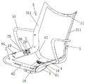
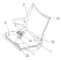
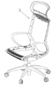
도 1은 본 발명의 제1 실시예에 따른 의자 구조를 나타내는 도면이다.
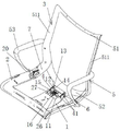
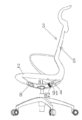
도 2는 본 발명의 의자 구조를 다른 각도에서 바라본 도면이다.
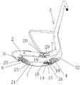
도 3은 일 측에서 바라본 본 발명의 의자 구조의 기본 상태를 나타내는 도면이다.
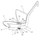
도 4는 일 측에서 바라본 본 발명의 의자 구조의 뒤로 젖혀진 상태를 나타내는 도면이다.
도 5는 일 측에서 바라본 본 발명의 의자 구조의 뒤로 젖혀진 상태에 대한 단면도이다.
도 6은 본 발명의 의자 구조의 뒤로 젖혀진 상태를 나타내는 도면이다.
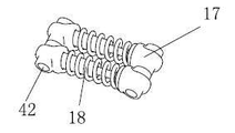
도 7은 본 발명의 일 실시예에 따른 압축 스프링을 나타내는 도면이다.
도 8은 본 발명의 일 실시예에 따른 압축 스프링의 분해도이다.
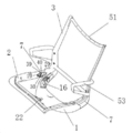
도 9는 본 발명의 제2 실시예에 따른 의자 구조를 나타내는 도면이다.
도 10은 본 발명의 제2 실시예에 따른 의자 구조의 정지 상태를 나타내는 조감도이다.
도 11은 본 발명의 제2 실시예에 따른 의자 구조의 뒤로 젖혀진 상태를 나타내는 조감도이다.
도 12는 일 측에서 바라본 본 발명의 제2 실시예에 따른 의자 구조의 기본 상태를 나타내는 도면이다.
도 13은 일 측에서 바라본 본 발명의 제2 실시예에 따른 의자 구조의 뒤로 젖혀진 상태를 나타내는 도면이다.
도 14는 본 발명의 제2 실시예에 따른 의자 구조의 정지 상태를 나타내는 도면이다.
도 15는 본 발명의 제2 실시예에 따른 의자 구조의 뒤로 젖혀진 상태를 나타내는 도면이다.
도 16은 본 발명의 제3 실시예에 따른 의자의 입체 구조를 나타내는 도면이다.
도 17은 본 발명의 제3 실시예에 따른 의자의 내부 평면 구조를 나타내는 도면이다.
도 18은 본 발명의 제3 실시예에 따른 의자의 커넥터와 받침, 위치 복원 스프링의 연결 구조를 나타내는 도면이다.
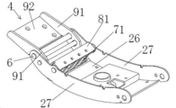
도 19는 본 발명의 제3 실시예에 따른 의자의 커넥터와 받침, 위치 복원 스프링의 연결 구조를 다른 각도에서 바라본 도면이다.
도 20은 본 발명의 제3 실시예에 따른 의자의 커넥터와 받침, 위치 복원 스프링이 결합된 내부 평면 구조를 나타내는 도면이다.
도 21은 본 발명의 제3 실시예에 따른 의자의 커넥터와 받침, 위치 복원 스프링이 결합된 외부 평면 구조를 나타내는 도면이다.
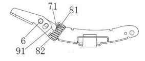
도 22는 본 발명의 제3 실시예에 따른 의자의 위치 복원 스프링과 상하 위치 한정판의 결합 구조를 나타내는 도면이다.
도 23은 본 발명의 제3 실시예에 따른 의자의 지지 부품이 연결봉을 통해 좌판과 결합하는 구조를 나타내는 도면이다.
도 24는 본 발명의 제3 실시예에 따른 의자의 한 세트의 연결봉의 결합 구조를 나타내는 도면이다.
도 25는 본 발명의 제3 실시예에 따른 의자의 지지 부품과 지레 구동 유닛의 결합 구조를 나타내는 도면이다. 1 is a view showing a chair structure according to a first embodiment of the present invention.
2 is a view showing the chair structure of the present invention from a different angle.
3 is a view showing the basic state of the chair structure of the present invention viewed from one side.
4 is a view showing a state in which the chair structure of the present invention as viewed from one side is bent backward.
5 is a cross-sectional view of the chair structure of the present invention as viewed from one side in a backwardly tilted state;
6 is a view showing a state in which the chair structure of the present invention is bent backward.
7 is a view showing a compression spring according to an embodiment of the present invention.
8 is an exploded view of a compression spring according to an embodiment of the present invention.
9 is a view showing a chair structure according to a second embodiment of the present invention.
10 is a bird's-eye view showing a stationary state of the chair structure according to the second embodiment of the present invention.
11 is a bird's-eye view showing a state in which the chair structure is bent backward according to the second embodiment of the present invention.
12 is a view showing a basic state of a chair structure according to a second embodiment of the present invention seen from one side.
13 is a view showing a state in which the chair structure is bent backward according to the second embodiment of the present invention viewed from one side.
FIG. 14 is a view showing a stationary state of the chair structure according to the second embodiment of the present invention. FIG.
15 is a view showing a state in which the chair structure is bent backward according to the second embodiment of the present invention.
16 is a diagram showing a three-dimensional structure of a chair according to a third embodiment of the present invention.
17 is a view showing an inner planar structure of a chair according to a third embodiment of the present invention.
18 is a view showing a connection structure of a chair connector, a support, and a position restoring spring according to a third embodiment of the present invention.
FIG. 19 is a view showing a connection structure of a connector, a support, and a position restoring spring of a chair according to a third embodiment of the present invention from another angle.
20 is a view showing an inner plan structure in which a chair connector, a support, and a position restoring spring are combined according to a third embodiment of the present invention.
FIG. 21 is a view showing an outer planar structure in which a chair connector, a support, and a position restoring spring are combined according to a third embodiment of the present invention.
FIG. 22 is a view showing a coupling structure of a position restoration spring of a chair and an upper and lower limited plate according to a third embodiment of the present invention. FIG.
23 is a view showing a structure in which a supporting part of a chair according to a third embodiment of the present invention is engaged with a seat plate through a connecting rod.
24 is a view showing a coupling structure of a connecting rod of a set of chairs according to a third embodiment of the present invention.
Fig. 25 is a view showing a coupling structure of a supporting part of a chair and a lever driving unit according to a third embodiment of the present invention. Fig.
이하에서는 구체적 실시예를 통해 그리고 도면과 결합하여 본 발명의 기술 방안에 대해 좀더 상세하게 설명한다. Hereinafter, the technical solution of the present invention will be described in more detail through concrete embodiments and in combination with the drawings.
먼저 본 발명의 각 부품의 참고 방위를 정의하면, 본 발명은 의자가 정상 사용되는 상태를 참고하여, 의자의 전방을 전방으로, 의자 등받이 유닛을 포함하는 의자 후방의 모든 위치를 후방이라 한다. First, with reference to the reference orientation of each part of the present invention, all positions on the rear of the chair including the chair back unit are referred to as the rear, with the front of the chair forward and the rear of the chair including the chair back unit with reference to the state where the chair is normally used.
실시예 1:Example 1:
도 1, 도 2가 나타내는 실시예에서, 의자 구조는 다음을 포함한다:In the embodiment shown in Figures 1 and 2, the chair structure includes:
의자의 좌판 유닛에 연결되는 좌판(1); 좌판(1)은 바람직하게는 금속 좌판이다; 의자 좌판 유닛(미도시)는 지지 기둥, 지지 기둥으로부터 하단 반경 방향으로 연장되는 다수의 지지 다리 및 지지 다리 끝단에 위치하는 바퀴를 포함하고, 상기 지지 기둥은 가스 실린더로 형성될 수 있다. A seat plate (1) connected to the seat plate unit of the chair; The seat (1) is preferably a metal seat; The chair seat plate unit (not shown) includes a support column, a plurality of support legs extending in the lower radial direction from the support column, and a wheel located at the support leg end, and the support column may be formed of a gas cylinder.
좌판(1)의 상부에 설치되고 좌판(1)과 대략적인 평형 상태를 유지하며, 전이 연결봉(8)을 통해 좌판(1)의 앞부분과 회전 연결되는 의자 지지 유닛(2); 상기의 의자 지지 유닛(2)은 좌우 대칭의 두 개의 지지봉(61)을 포함하고, 두 개의 지지봉(61)의 앞부분은 가로대(62)를 통해 하나로 연결되고; 가로대(62)는 전이 연결봉(8)을 통해 좌판(1)의 앞부분과 회전 연결되며; 의자 지지 유닛(2)의 앞단은 아래 방향 뒤쪽으로 구부러져 뻗어 사람이 앉은 자세의 구조로 설치되고, 의자 지지 유닛(2)은 좌판(1)과 프레임 구조로 회전 연결되어; 사람이 앉은 자세의 구조는 인체공학에 부합하여, 앉았을 때 훨씬 편하고, 다리 부분의 감촉이 좋다;A
전이 연결봉(8)의 양 단은 각각 활 모양의 연결봉 위치 한정 구조(25)가 설치되고; 의자 지지 유닛(2)이 전이 연결봉(8)과 연결되는 일 단은 제1 위치 한정 구조(9)가 형성된 연결봉 위치 한정 구조에 대응된다. 제1 위치 한정 구조(9)는 활 모양의 위치 한정 돌기이고, 제2 위치 한정 구조(21)은 활 모양의 위치 한정 돌기 또는 위치 한정 핀 또는 위치 한정 톱니일 수 있다. 본 실시예에서 제2 위치 한정 구조(21)는 위치 한정 핀을 예시한다(도 3 참조).Both ends of the
의자 등받이 유닛(3)은, 커넥터(4)와 지지대(5)를 포함하고, 커넥터(4)는 좌판(1)의 뒷부분과 피봇(6)을 통해 회전 연결되고, 지지대(5)의 회전 시 커넥터(4)가 에워싸는 피봇(6)과 함께 회전하며; 커넥터(4)는 의자 등받이 유닛(3)과 좌판(1)의 연결체에 대응된다. 상술한 지지대(5)는 등받이 프레임 상부 지지대(51) 및 등받이 프레임의 지지대(5) 좌우 양측의 아래 방향으로 연장되는 측면 지지대(511), 두 개의 측면 지지대(511)의 하단 중간을 향해 모이도록 형성되는 등받이 프레임 하부 지지대(52), 등받이 프레임 하부 지지대(52)는 앞쪽으로 연장되어 커넥터(4)와 연결된다; 지지봉(61)과 측면 지지대(511) 사이에는 팔걸이(53)가 연결된다. The seat back
지레 구동 유닛(7)은, 상기 지지대(5)와 의자 지지 유닛(2) 사이에 연결되고, 두 개의 지레 구동 유닛(7)은 각각 두 개의 지지봉(61) 뒷부분에 회전 연결되며; 상기 지레 구동 유닛(7)은 의자 지지 유닛(2)에 대응되고 두 개가 좌우 대칭되고, 지레 구동 유닛(7)은 측면 지지대(511) 하단 부위로부터 앞쪽을 향해 연장되어 형성되고; 상기 지레 구동 유닛(7)은 의자 지지 유닛(2)과 대략 동일한 면에 위치하여, 지레 구동 유닛(7)이 지지봉(61)가 대략 하나의 직선으로 연결되고 양자 모두 좌판(1)과 대략적인 평형을 유지하고 있다고 할 수 있다. 상기 지레 구동 유닛은 의자 지지 유닛과 대략 동일한 면에 위치하나, 이는 양자가 모두 동일한 평면에 위치함을 의미하는 것은 아니고, 광의적으로 양자 사이에 20도 이상의 협각이 나타나는 것을 제외하는 것으로, 더 바람직하게는 의자에 너무 크게 우뚝 솟는 형상이 나타나지 않도록 하여, 간결하고 원활하게 설치되도록 한다. The
지레 구동 유닛(7)은 스스로 구동 능력을 갖춘 것은 아니고, 의자 등받이 유닛(3)의 회전이 전달되는 것으로; 지지대(5)가 초기 위치에서 뒤쪽으로 회전하는 때에, 지레 구동 유닛(7)을 통해 의자 지지 유닛(2)이 들여 올려지고; 지지대(5)가 원래 위치로 복원하는 때에, 마찬가지로 지레 구동 유닛(7)을 통해 의자 지지 유닛(2)이 처음 위치로 복원하게 된다. 지지대(5)는 인체 배부 구조와 매칭되어 일체형으로 설치되는 부재이다. The
좌판(1)은 보드(26)과 두 측판(27)을 포함하고(도 5 참조), 보드(26)은 앞뒤로 연장되는 방향으로 활 모양의 구조로 설치된다. 커넥터(4)는 U자 구조로 설치되는데, 구체적으로, 커넥터(4)는 이격하여 설치된 두 개의 암(41)을 구비하여, 커넥터(4)의 앞단은 암(41)이 좌판(1)의 후단과 내외부로 매칭되고 회전 연결될 수 있다.The
커넥터(4)의 두 개의 암(41)과 좌판(1)의 두 개의 측판(27)은 각각 설치된 피봇 연결 홀(12)에서 서로 회전 매칭되고, 커넥터(4)와 좌판(1)은 피봇 연결 홀(12) 내부의 피봇(6)의 설치로 회전 연결된다. The two
좌판(1) 또는 커넥터(4) 중 하나에 위치 한정 슬롯(15)이 설치되고, 대응되는 다른 하나에는 위치 한정축(14)이 설치되는데(도 3, 도 5 참조), 위치 한정 슬롯(15)은 피봇 연결 홀(12)의 전방에 설치되고, 커넥터(4)는 위치 한정축(14)을 통해 전후 움직임의 범위가 한정되도록 한다. 커넥터(4)의 후단 양측은 지지대(5)에 설치된 고정 클램프 구조(13)와 매칭된다.The
도 2, 3, 5, 7, 8에 도시되는 바와 같이, 좌판(1)과 커넥터(4) 사이에 위치 복원 장치(16)가 설치될 수 있다; 구체적으로, 위치 복원 장치(16)는 2 내지 5개가 나란히 배열되어 설치되는 위치 복원 압축 스프링으로; 위치 복원 압축 스프링의 양단은 각각 좌판(1) 및 커넥터(4)와 상호 연결되는데; 구체적으로, 좌판(1)과 커넥터(4)에 각각 횡으로 핀 샤프트(10)가 구비되고, 위치 복원 압축 스프링의 양단은 각각 좌판(1), 커넥터(4)의 핀 샤프트(10)와 연결된다. 위치 복원 압축 스프링은 압축 스프링 본체(18)와 압축 스프링 본체 양단에 설치되는 연결 소켓(17)을 포함하고, 연결 소켓(17)에는 축 홀(42)이 구비되며, 상기 핀 샤프트(10)는 연결 소켓(17)의 축 홀(42)을 관통하여 설치된다. As shown in Figs. 2, 3, 5, 7 and 8, a
지레 구동 유닛(7)은 지지대(5)와 일체로 설치되거나; 또는 지레 구동 유닛(7)은 지지대(5)와 별도로 설치되어 고정 연결될 수 있다. 본 실시예에서 지레 구동 유닛(7)은 지지대(5)와 일체로 구비된다. The
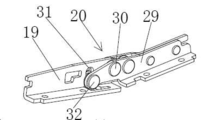
지레 구동 유닛(7)은 의자 지지 유닛(2)과 한 세트의 연결봉(20)을 통해 회전 연결된다. 연결봉(20)은 제1 연결봉(19)과 제2 연결봉(29)을 포함하고, 제1 연결봉(19)은 의자 지지 유닛(2)과 3개의 나사와 고정 연결되고, 제2 연결봉(29)은 지레 구동 유닛(7)과 3개의 나사와 고정 연결되며, 제1 연결봉(19)과 제2 연결봉(29)은 회전축(30)을 통해 회전 연결된다. 제1 연결봉(19)과 제2 연결봉(29) 중 임의의 하나에 위치 한정 홀(31)이 구비되고, 대응하는 다른 하나에는 위치 한정 핀 샤프트(32)가 구비되며, 위치 한정 핀 샤프트(32)는 위치 한정 홀(31)에 삽입된다. The
이러한 의자 구조는, 전이 연결봉(8)을 통해 의자 앞부분과 회전 연결되는 의자 지지 유닛(2), 의자 등받이 유닛 및 지레 구동 유닛에 의해, 4-링크 지레 연결 암 구조를 형성한다(도 3, 4 참조). 사용 과정에서, 인체가 의자 등받이 유닛에 힘을 가하여, 회전 연결되는 지레 구동 유닛, 의자 등받이 유닛 및 의자 지지 유닛 사이에 서로 힘이 전달됨에 따라, 의자 지지 유닛이 좌판에서 상하로 움직이고, 전후로 움직일 수 있게 한다(도 5, 도 6 참조).This chair structure forms the four-link lever coupling arm structure by the
의자는 다음을 포함한다: Chairs include:
상기 의자 구조;The chair structure;
의자 좌판 유닛; 의자 좌판 유닛(미도시)는 지지 기둥, 지지 기둥의 하단에서 반경 방향으로 연장되는 다수의 지지 다리 및 지지 다리 끝단의 바퀴를 포함하고, 지지 기둥은 좌판에 연결되고, 상기 지지 기둥은 가스 실린더일 수 있다. A chair seat unit; The chair seat plate unit (not shown) includes a support column, a plurality of support legs extending radially from the lower end of the support column, and wheels of the support leg end, the support column being connected to the seat plate, .
네트(미도시); 상기 네트는 의자 등받이 유닛, 지레 구동 유닛 및 의자 지지 유닛에서 위로부터 아래로 팽팽하게 당겨지고, 상기 네트는 위에서 아래로 일체로 연결된다. Net (not shown); The net is pulled tightly from top to bottom in the seat back unit, the lever drive unit and the chair support unit, and the net is integrally connected from top to bottom.
실시예 2:Example 2:
도 9, 도 10, 도 11에서 도시하는 실시예에서:In the embodiment shown in Figures 9, 10 and 11:
의자 구조는 다음을 포함한다:The chair structure includes:
좌판(1); 상기 좌판(1)은 의자 좌판 유닛에 연결되어 설치되고; 좌판(1)은 Y자 구조로 형성된다. A
의자 지지 유닛(2); 상기 의자 지지 유닛(2)은 좌판(1) 상단에 설치되고; 의자 지지 유닛(2)은 앞단이 상하로 구부러져 연장되어 사람이 앉은 자세의 구조로 설치되며, 의자 지지 유닛(2)은 좌판(1)이 프레임 구조와 회전 연결된다. A chair support unit (2); The chair support unit (2) is installed at the upper end of the seat (1); The
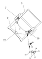
어댑터(22); 상기 어댑터(22)는 의자 지지 유닛(2) 및 좌판(1) 사이에 위치하고, 어댑터(22)의 양단은 각각 의자 지지 유닛(2) 전단부와 좌판(1) 전단부에 회전 연결된다;An
의자 등받이 유닛(3); 상기 상기 의자 등받이 유닛(3)은 좌판(1) 후단부와 피봇(6)을 통해 회전 연결된다;A chair back
지레 구동 유닛(7); 상기 의자 등받이 유닛(3)과 의자 지지 유닛(2) 사이에 연결되고, 의자 등받이 유닛(3)이 초기 위치에서 뒤쪽으로 회전하는 때에, 지레 구동 유닛(7)을 통해 의자 지지 유닛(2)이 들여 올려지고 의자 지지 유닛(2)을 뒤로 이동시키며; 의자 등받이 유닛(3)이 위치 복원하는 때에, 지레 구동 유닛(7)을 통해 의자 지지 유닛(2)이 원래 위치로 복원된다. A
의자 등받이 유닛(3)은 인체 배부 구조와 매칭되어 일체로 설치되는 부재로, 의자 등받이 유닛(3)은 등받이 프레임 상부 지지대(51), 등받이 프레임 하부 지지대(52) 및 양측 팔걸이(53)를 포함하고, 등받이 프레임 하부 지지대(52)는 앞쪽으로 일체로 연장하는 좌판(1)과 매칭되어 회전하는 연결 구조로 설치된다.The seat back
좌판(1)은 의자 등받이 유닛(3)과 연결되는 곳에 위치 복원 장치(16)가 설치된다. 위치 복원 장치(16)는 비틀림 스프링 유닛일 수 있다. 비틀림 스프링 유닛은 각각 좌판(1)과 의자 등받이 유닛(3)의 비틀림 스프링 소켓(23)에 연결되고, 비틀림 스프링 소켓(23) 내부에 설치되는 비틀림 스프링(24)을 포함한다. The seat plate (1) is provided with a position restoring device (16) at a position connected to the seat back unit (3). The
비틀림 스프링 유닛은 각각 좌판(1)과 의자 등받이 유닛(3)에 연결되고 비틀림 스프링 소켓(23) 내부에 설치되는 비틀림 스프링(24)을 포함한다. The torsion spring units each include a
비틀림 스프링 소켓(23)은 비틀림 스프링 전단 소켓(33)과 비틀림 스프링 후단 소켓(34)을 포함하고, 비틀림 스프링 전단 소켓(33)과 비틀림 스프링 후단 소켓(34)에는 각각 한 쌍의 어댑터 벽(35)이 설치되고, 비틀림 스프링 전단 소켓(33)과 비틀림 스프링 후단 소켓(34)의 어댑터 벽(35)은 회전 연결된 후 설치 캐비티(36)를 형성하며, 비틀림 스프링(24)은 비틀림 스프링 본체(37)와 토크 암(torque arm, 38)을 포함하고, 비틀림 스프링(24)은 설치 캐비티(36)의 내부에 위치하여, 토크 위치 복원을 실현한다. The
지레 구동 유닛(7)은 한 세트의 연결봉(20)으로, 제1 연결봉(19) 및 제2 연결봉(29)을 포함하고, 제1 연결봉(19)은 의자 지지 유닛(2)과 고정되어 연결되고, 제2 연결봉(29)은 지레 구동 유닛(7)과 고정되어 연결되며, 제1 연결봉(19) 및 제2 연결봉(29)은 회전축(30)을 통해 회전 연결된다. 제1 연결봉(19) 및 제2 연결봉(29) 중 임의의 하나는 위치 한정 돌기(39)가 설치되고, 대응하는 다른 하나에는 위치 한정 홈(40)이 형성된다. The
이러한 의자 구조는 또한, 의자 앞부분과 회전 연결되는 의자 지지 유닛, 어댑터, 의자 등받이 유닛 및 지레 구동 유닛에 의해, 의자 등받이 유닛이 직접 좌판 후단과 회전 연결되어, 하나의 지레 연결 암 구조를 형성한다. 사용 과정에서(도 14, 도 15 참조), 인체가 의자 등받이 유닛에 힘을 가하여, 회전 연결되는 지레 구동 유닛, 의자 등받이 유닛 및 의자 지지 유닛 사이에 서로 힘이 전달됨에 따라, 의자 지지 유닛이 좌판에서 상하로 움직이고, 전후로 움직일 수 있게 한다(도 12, 도 13 참조).The chair structure further includes a chair support unit, an adapter, a chair back unit and a jaw driving unit rotatably connected to the front of the chair, and the chair back unit is directly connected to the seat back rear end to form a single lever connection structure. In the course of use (see Figs. 14 and 15), as the human body applies a force to the chair back unit and forces are transmitted to each other between the rotationally connected jaw driving unit, the chair back unit and the chair support unit, (See Figs. 12 and 13).
해당 실시예는 다음을 포함하는 의자를 제공한다:The embodiment provides a chair comprising:
상기 의자 구조; The chair structure;
의자 구조를 지지하는데 사용되는 좌판 유닛;A seat plate unit used to support the chair structure;
네트(미도시); 상기 네트는 의자 등받이 유닛, 지레 구동 유닛 및 의자 지지 유닛에서 위로부터 아래로 팽팽하게 당겨지고, 상기 네트는 위에서 아래로 일체로 연결된다. Net (not shown); The net is pulled tightly from top to bottom in the seat back unit, the lever drive unit and the chair support unit, and the net is integrally connected from top to bottom.
상기 실시예에서 기술된 의자 구조는, 인체가 뒤로 기대어 의자 등받이 유닛(3)에 힘(경압)을 가하는 때에, 의자 등받이 유닛(3)은 경압력 작용으로 뒤로 운동하고, 뒤로의 경압력은 의자 등받이 유닛(3)을 통해 아래 방향으로 지레 구동 유닛(7)에 전달되며, 지레 구동 유닛(7)은 의자 지지 유닛(2)이 위로 들어 올려져 뒤로 운동하도록 하여, 인체 및 의자 구조가 뒤로 젖혀지게 한다; 인체가 앞으로 기우는 때에, 의자 등받이 유닛(3)에 경압력이 소멸하여, 위치 복원 장치가 의자 등받이 유닛(3)이 원래 위치로 복원되도록 한다. 나아가, 해당 의자 구조는 전이 연결봉과 연결봉을 넘는 한 세트의 지레 연결 구조를 통해 각 유닛 사이의 회전을 실현하고, 위치 한정 장치에 의해 위치 한정을 수행한다. 힘의 가함과 전달에 의해, 각 유닛 사이의 동작이 한층 원활할 수 있다. In the chair structure described in the above embodiment, when the human body leans back and applies a force (an urging force) to the chair back
이러한 의자 구조와 의자는, 어떠한 재료로 제작하기에도 적합하고, 어떠한 사람에게도 사용이 적합하며, 위치 복원 장치는 디자인, 인체 체중 등 요구되는 사항에 따라 설치될 수 있어, 서로 다른 사용 요구 및 서로 다른 유형의 사람의 사용을 모두 만족시킬 수 있으며, 나아가 사람이 앉았을 때 편안함을 느낄 수 있다. Such a chair structure and chair are suitable to be made of any material, suitable for use by any person, and the position restoring device can be installed according to requirements such as design, body weight, and the like, It is possible to satisfy all kinds of people's use, and also to feel comfortable when a person is seated.
실시예 3: 본 실시예는 실시예 1의 지레 구동 유닛, 의자 등받이 유닛, 의자 지지 유닛, 전이 연결봉 및 좌판 등 4-링크 구성이 구조 관계에서 기본적으로 동일하나, 본 실시예는 실시예 1와 다음의 측면에서 주요한 차이가 있다. 도 16 내지 25에 도시하는 바와 같이, 의자 등받이 유닛(3)과 좌판(1) 사이에 종 방향으로 위치 복원 스프링(71)이 설치되는데, 구체적으로, 상기 위치 복원 스프링(71)이 피봇(6) 대비 훨씬 앞쪽에 위치한다. 종 방향으로 설치되었다 함은 엄밀한 의미에서의 종 방향으로 한정되는 것은 아니고, 나아가 반드시 위치 복원 스프링(71)의 중심선이 연직선과 겹쳐짐을 나타낸다고 할 수 없고, 광의상 횡 방향으로의 설치를 배제하는 정도를 이르며, 보다 바람직하게는 의자 등받이 유닛의 하단과 회전 시에 위쪽으로 힘이 가해지는 방향과 기본적으로 일치한다. Third Embodiment The present embodiment is basically the same in structure relation to the four-link configuration of the lever driving unit, the chair back unit, the chair support unit, the transition connecting rod and the seat plate of the first embodiment, There are major differences in the following aspects. 16 to 25, a
구체적으로, 상기 위치 복원 스프링(71)은 압축 스프링으로, 좌판(1)의 상단에 상부 위치 제한판(81)이 설치되고, 위치 복원 스프링(71)은 의자 등받이 유닛(3)의 하단과 상부 위치 제한판(81) 사이에 설치된다. Specifically, the
더 구체적으로 말하면, 도 18 내지 21에 도시되는 바와 같이, 좌판(1)은 보드(26)과 보드(26)을 따라 양측 위쪽으로 연장되는 두 개의 측판(27)을 포함한다. 상기 의자 등받이 유닛(3)은 커넥터(4)와 의자 등받이로 사용되는 지지대(5)를 포함하고, 상기 커넥터(4)는 좌우 대칭인 끝판(91) 및 두 개의 끝판(91)에 연결되는 연결판(92)을 포함하고, 끝판(91)과 측판(27)은 평행하여 설치되고, 상기 끝판(91) 및 측판(27)은 피봇(6)을 통해 회전 연결된다; 상기 상부 위치 제한판(81)은 양단을 통해 아래 방향으로 연결되는 러그(lug, 811)를 통해 좌판의 양 측판(27)과 힌지 연결되며, 커넥터(4)에 하부 위치 제한판(82)이 설치되는데, 하부 위치 제한판(82)은 양단 위 방향으로 연장되는 러그(811)를 통해 양측의 끝판(91)과 힌지 연결되고, 위치 복원 스프링(71)은 상부 위치 제한판(81)과 하부 위치 제한판(82) 사이에 설치된다. More specifically, as shown in Figs. 18 to 21, the
더 구체적으로 말하면, 상기 위치 복원 스프링(71)은 나란히 배열되는 적어도 두 개로, 그 좌측에서 우측으로 좌판(1) 내에 설치되고, 상부 위치 제한판(81)과 하부 위치 제한판(82)에 적어도 두 개의 위치 고정 기둥(83)이 설치되며, 위치 복원 스프링(71)의 상하 양단은 각각 대응되는 위치 고정 기둥(83)과 커플링 되어 위치 고정된다. More specifically, the position restoring springs 71 are installed in the
1: 좌판, 2: 의자 지지 유닛, 3: 의자 등받이 유닛, 4: 커넥터(connector), 5: 지지대, 6: 피봇, 7: 지레 구동 유닛, 8: 전이 연결봉, 9: 제1 위치 한정 구조, 10: 핀 샤프트, 11: 위치 복원 장치 신축 슬라이드(slide), 12: 피봇 연결 홀(hole), 13: 고정 클램프(clamp) 구조, 14: 위치 한정축, 15: 위치 한정 슬롯(slot), 16: 위치 복원 장치, 17: 연결 소켓(socket), 18: 압축 스프링 본체, 19: 제1 연결봉, 20: 연결봉, 21: 제2 위치 한정 구조, 22: 어댑터(adapter), 23: 비틀림 스프링 소켓, 24: 비틀림 스프링, 51: 등받이 프레임 상부 지지대, 511: 측면 지지대, 52: 등받이 프레임 하부 지지대, 53: 팔걸이, 25: 연결봉 위치 한정 구조, 26: 보드, 27: 측판, 29: 제2 연결봉, 30: 회전축, 31: 위치 한정 홀, 32: 위치 한정 핀 샤프트, 33: 비틀림 스프링 전단 소켓, 34: 비틀림 스프링 후단 소켓, 35: 어댑터 벽, 36: 설치 캐비티(cavity), 37: 비틀림 스프링 본체, 38: 토크 암(torque arm), 39: 위치 한정 돌기, 40: 위치 한정 홈(groove), 41: 암(arm), 42: 축 홀, 61: 지지봉, 62: 가로대1: seat plate, 2: chair support unit, 3: chair backrest unit, 4: connector, 5: support, 6: pivot, 7: lever drive unit, 8: The present invention relates to a position restoring device and a position restoring device which are capable of restraining the position of the pin shaft by means of a pin retracting mechanism. And a torsion spring socket for connecting the torsion spring socket and the torsion spring socket to each other, wherein the torsion spring socket comprises a torsion spring socket, The present invention relates to a torsion spring for a torsion spring of a torsion spring which comprises a torsion spring and a torsion spring. 33: Torsion spring shear socket, 34: Torsion spring rear socket, 35: Adapter wall, 36: Installation cavity the present invention relates to a torsional spring comprising a torsion spring main body and a torsion spring main body, a torque arm, 62: Crossbar
Claims (40)
상기 좌판 상부에 설치되고, 전단 부분이 상기 좌판의 전단과 전이 연결봉을 거쳐 회전 연결되는 의자 지지 유닛;
상기 좌판의 후단부와 피봇에 의해 회전 연결되는 의자 등받이 유닛;
상기 의자 등받이 유닛과 상기 의자 지지 유닛 사이에 연결되고, 상기 의자 지지 유닛의 후단부와 회전 연결되며, 상기 의자 지지 유닛과 대체로 동일한 면에 위치하는 지레 구동 유닛을 포함하고; 상기 의자 등받이 유닛이 시작 위치에서 피봇을 둘러싸고 뒤쪽으로 회전하는 때에, 상기 지레 구동 유닛을 통해 상기 의자 지지 유닛의 후단부가 뒤로 기울어져 들여 올려지고, 동시에 상기 전이 연결봉 및 상기 의자 지지 유닛의 전단부가 당겨진 것을 특징으로 하는 의자 구조.A seat mounted to be connected to the chair seat unit;
A chair support unit installed at an upper portion of the seat and having a front end connected to the front end of the seat through a transition connecting rod;
A chair back unit rotatably connected to the rear end of the seat by pivot;
And a lever drive unit connected between the chair back unit and the chair support unit and rotatably connected to the rear end of the chair support unit and positioned on substantially the same plane as the chair support unit; The rear end of the chair support unit is tilted backward through the lever drive unit when the chair back unit surrounds the pivot and rotates backward at the start position and at the same time the front end of the transition connection rod and the chair support unit is pulled The chair structure being characterized by:
상기 의자 등받이 유닛은 커넥터와 지지대를 포함하고, 상기 커넥터는 피봇을 통해 상기 좌판 후단부와 회전 연결되며, 상기 지지대는 등받이 프레임 상부 지지대 및 등받이 프레임 상부 지지대의 좌우 양측의 아래 방향으로 연장되는 측면 지지대를 포함하고, 상기 지레 구동 유닛은 좌우 대칭의 두 개로 형성되며, 지레 구동 유닛은 측면 지지대의 하단부 위치에서 앞쪽으로 연장되어 형성되고, 두 개의 측면 지지대의 하단은 중간을 향해 합류하고 앞쪽으로 연장되어 커넥터와 연결된되고; 상기 의자 지지 유닛은 좌우 대칭의 두 개의 지지봉을 포함하고, 두 개의 지지봉의 후단부는 각각 두 개의 지레 구동 유닛과 회전 연결되며, 두 개의 지지봉의 전단부는 가로대를 통해 일체로 연결되며; 지레 구동 유닛은 지지봉과 대체로 하나의 직선으로 연결되는 것을 특징으로 하는 의자 구조.The method according to claim 1,
The seat back unit includes a connector and a support, the connector being rotatably connected to the seat back end via a pivot, the support base comprising a back support frame and a back support frame extending downward on both left and right sides of the backrest frame upper support, Wherein the lever drive unit is formed of two left and right symmetrical, the lever drive unit is formed to extend forward at the lower end position of the side support, the lower ends of the two side support members merge toward the middle and extend forward Connected to the connector; Wherein the chair support unit includes two support rods symmetrical in the left and right directions and the rear ends of the two support rods are rotatably connected to the two guide drive units respectively and the front ends of the two support rods are integrally connected through the cross bar; Wherein the lever drive unit is connected to the support rod in a generally straight line.
상기 의자 지지 유닛의 전단은 아래 뒤쪽 방향으로 구부러져 연장되어 사람이 앉는 자세의 구조로 설치되는 것을 특징으로 하는 의자 구조.The method according to claim 1,
Wherein the front end of the chair support unit is bent and extended in a backward direction so as to be installed in a posture in which a person sits.
상기 의자 지지 유닛은 전이 연결봉과 연결되는 일단에 제1 위치 한정 구조가 설치되고, 상기 좌판은 전이 연결봉과 회전 연결되는 곳에 제2 위치 한정 구조가 설치되는 것을 특징으로 하는 의자 구조.The method according to claim 1,
Wherein the chair support unit is provided with a first position limiting structure at one end connected to the transition connecting rod and a second position limiting structure is provided at a position where the seat plate is rotationally connected with the transition connection rod.
상기 제1 위치 한정 구조는 활 모양의 위치 한정 돌기인 것을 특징으로 하는 의자 구조.5. The method of claim 4,
Wherein the first position defining structure is an arcuate position defining protrusion.
상기 제2 위치 한정 구조는 활 모양의 위치 한정 돌기 또는 위치 한정 핀 또는 위치 한정 톱니인 것을 특징으로 하는 의자 구조.5. The method of claim 4,
Wherein the second position limiting structure is an arcuate position limiting protrusion or a position limiting pin or a position limiting saw.
상기 좌판은 받침 및 두 개의 측판을 포함하고, 상기 받침은 전후 길이 방향으로 활 모양의 구조가 설치되는 것을 특징으로 하는 의자 구조.3. The method of claim 2,
Wherein said seat comprises a base and two side plates, said base being provided with an arcuate structure in the longitudinal and longitudinal direction.
상기 커넥터는 U자 구조로 설치되고, 상기 커넥터의 전단은 좌판의 후단과 내외부로 합해지고 회전 연결될 수 있는 것을 특징으로 하는 의자 구조.8. The method of claim 7,
Wherein the connector is installed in a U-shaped structure, and the front end of the connector is combined and rotatably connected to the rear end of the seat back and forth.
상기 커넥터과 좌판이 회전 매칭되는 곳의 양 측판에 각각 피봇 연결 홀이 설치되고, 피봇은 상기 피봇 연결 홀 내부에 설치되는 것을 특징으로 하는 의자 구조.9. The method of claim 8,
Wherein a pivot connection hole is provided on both side plates of the connector where the connector and the seat are rotationally matched, and a pivot is installed inside the pivot connection hole.
상기 좌판 또는 커넥터 중 하나에 위치 한정 슬롯이 설치되고, 대응되는 다른 하나에는 위치 한정축이 설치되며, 상기 위치 한정 슬롯은 피봇 연결 홀의 전방에 설치되고, 상기 커넥터는 위치 한정축을 통해 전후 움직임에 대한 위치 한정을 실현할 수 있는 것을 특징으로 하는 의자 구조.10. The method of claim 9,
Wherein the position limiting slot is provided in one of the seat plate or the connector and the other is provided with a position limiting axis which is provided in front of the pivot connection hole, And the position limitation can be realized.
상기 커넥터의 후단 양측이 매칭되는 지지대에 고정 클램프 구조를 설치하는 것을 특징으로 하는 의자 구조.3. The method of claim 2,
Wherein a fixing clamp structure is provided on a supporting base on which both ends of the rear end of the connector are matched.
상기 좌판과 커넥터 사이에 위치 복원 장치를 설치하는 것을 특징으로 하는 의자 구조.3. The method of claim 2,
And a position restoring device is provided between the seat and the connector.
상기 위치 복원 장치는 적어도 하나의 위치 복원 압축 스프링인 것을 특징으로 하는 의자 구조.13. The method of claim 12,
Wherein the position restoration device is at least one position restoring compression spring.
상기 위치 복원 압축 스프링은 좌판, 커넥터로 둘려진 공간에 설치되고, 상기 위치 복원 압축 스프링의 양단은 각각 좌판 및 커넥터와 연결되는 것을 특징으로 하는 의자 구조.14. The method of claim 13,
Wherein the position restoring compression spring is installed in a space surrounded by a seat plate and a connector, and both ends of the position restoring compression spring are connected to a seat plate and a connector, respectively.
상기 좌판 및 커넥터에 각각 횡으로 핀 샤프트가 설치되고, 위치 복원 압축 스프링의 양단은 각각 좌판 및 커넥터의 핀 샤프트가 연결되는 것을 특징으로 하는 의자 구조.15. The method of claim 14,
Wherein the seat plate and the connector are each provided with a pin shaft laterally and both ends of the position restoring compression spring are respectively connected to the seat plate and the pin shaft of the connector.
상기 위치 복원 압축 스프링은 압축 스프링 본체와 압축 스프링 본체의 양단에 설치되는 연결 소켓을 포함하고, 연결 소켓에는 축 홀이 형성되며, 상기 핀 샤프트는 연결 소켓의 축 홀을 관통하여 설치되는 것을 특징으로 하는 의자 구조.16. The method of claim 15,
The position restoring compression spring includes a compression spring body and a connection socket provided at both ends of the compression spring body. A shaft hole is formed in the connection socket, and the pin shaft is installed through the shaft hole of the connection socket. Chair structure.
상기 지레 구동 유닛과 지지대는 일체로 설치되는 것을 특징으로 하는 의자 구조.3. The method of claim 2,
Wherein the lever drive unit and the support base are integrally installed.
상기 지레 구동 유닛 및 지지대는 분리되어 설치된 후 고정 연결되는 것을 특징으로 하는 의자 구조.3. The method of claim 2,
Wherein the lever driving unit and the support frame are separately installed and then fixedly connected.
상기 지레 구동 유닛과 지지대는 한 세트의 연결봉을 통해 회전 연결되는 것을 특징으로 하는 의자 구조.The method according to claim 1,
Wherein the lever drive unit and the support are rotationally connected through a set of connecting rods.
상기 연결봉은 제1 연결봉 및 제2 연결봉을 포함하고, 상기 제1 연결봉은 상기 의자 지지 유닛과 고정 연결되고, 상기 제2 연결봉은 상기 상기 지레 구동 유닛과 고정 연결되며, 상기 제1 연결봉 및 제2 연결봉은 회전축을 통해 회전 연결되는 것을 특징으로 하는 의자 구조.20. The method of claim 19,
Wherein the connecting rod includes a first connecting rod and a second connecting rod, the first connecting rod is fixedly connected to the chair supporting unit, the second connecting rod is fixedly connected to the lever driving unit, And the connecting rod is rotatably connected through the rotating shaft.
상기 제1 연결봉 및 제2 연결봉 중 임의의 하나에 위치 한정 홀이 형성되고, 대응되는 다른 하나에는 위치 한정 핀 샤프트가 설치되는 것을 특징으로 하는 의자 구조.21. The method of claim 20,
Wherein a position defining hole is formed in any one of the first connecting rod and the second connecting rod, and a position limiting pin shaft is provided in the other corresponding one of the first connecting rod and the second connecting rod.
상기 의자 구조를 지지하는데 사용되는 좌판 유닛;
의자 등받이 유닛, 지레 구동 유닛 및 의자 지지 유닛에서 위로부터 아래로 팽팽하게 당겨지고, 위에서 아래로 일체로 연결되는 네트를 포함하는 것을 특징으로 하는 의자 구조.A chair structure according to any one of claims 1 to 21;
A seat plate unit used to support the chair structure;
A chair backrest unit, a jaw driving unit, and a chair support unit, and a net integrally connected from the top to the bottom.
상기 좌판 상단에 설치되고, 전단부가 좌판 전단부와 전이 연결봉을 통해 회전 연결되는 의자 지지 유닛;
상기 의자 좌판 유닛 및 의자 지지 유닛 사이에 연결되고, 의자 지지 유닛 후단부와 회전 연결되며, 대체로 의자 지지 유닛과 동일한 면에 놓이는 지레 구동 유닛으로; 의자 등받이 유닛이 처음 위치로부터 피봇을 에워싸고 뒤로 회전하는 때에, 지레 구동 유닛을 통해 의자 지지 유닛의 후단부가 기울어져 뒤쪽으로 들여 올려지고, 동시에 전이 연결봉 및 의자 지지 유닛 전단부를 끌어 올리고;
의자 등받이 유닛과 좌판 사이에 종 방향으로 설치되고, 의자 등받이 유닛이 뒤쪽으로 회전하는 때에 위치 복원 스프링이 반작용력을 생성하는 위치 복원 스프링을 포함하는 것을 특징으로 하는 의자 구조. A seat mounted to be connected to the chair seat unit;
A chair support unit installed at an upper end of the seat and having a front end rotatably connected through a seat front end and a transition connection rod;
A lever drive unit connected between the chair seat plate unit and the chair support unit and rotatably connected to the rear end of the chair support unit and placed on the same plane as the chair support unit; When the chair back unit surrounds the pivot from its initial position and rotates backward, the rear end of the chair support unit is tilted backward through the lever drive unit and simultaneously pulls up the front end of the transition connecting rod and the chair support unit;
And a position restoration spring installed longitudinally between the chair back unit and the seat back and generating a reaction force when the seat back unit rotates backward.
상기 위치 복원 스프링은 피봇과 대비하여 더 앞쪽 위치로 설치되는 것을 특징으로 하는 의자 구조. 24. The method of claim 23,
Wherein the position restoring spring is installed in a forward position relative to the pivot.
상기 위치 복원 스프링은 압축 스프링인 것을 특징으로 하는 의자 구조.24. The method of claim 23,
Wherein the position restoring spring is a compression spring.
상기 좌판 상단에 위치 한정판이 설치되고, 상기 위치 복원 스프링은 의자 등받이 유닛 하단과 위치 한정판 사이에 설치되는 것을 특징으로 하는 의자 구조.24. The method of claim 23,
Wherein the position restraining spring is installed between the lower end of the chair back unit and the position limiting plate.
상기 좌판은 받침과 받침 양측으로부터 위로 연장되는 두 개의 측판을 포함하고, 상기 의자 등받이 유닛은 커넥터 및 의자 등받이로 사용되는 지지대를 포함하며, 상기 커넥터는 좌우 대칭의 끝판 및 두 개의 끝판에 연결되는 연결판을 포함하고, 상기 끝판과 측판은 피봇을 통해 회전 연결되고; 상기 상부 위치 제한판은 양단의 러그를 통해 좌판의 양 측판과 힌지 연결 설치되고, 커넥터에 하부 위치 제한판이 설치되고, 상기 하부 위치 제한판은 양단의 러그를 통해 끝판과 힌지 연결 설치되며, 위치 복원 스프링은 상부 위치 제한판과 하부 위치 제한판 사이에 설치되는 것을 특징으로 하는 의자 구조.27. The method of claim 26,
Wherein said seat back comprises two side plates extending upwardly from both sides of said base and said backrest, said backrest unit comprising a support for use as a connector and a chair backrest, said connector comprising a left and right symmetrical end plate and a connection Wherein the end plate and the side plate are rotationally connected through a pivot; The upper position limiting plate is hinge-connected to both side plates of the seat plate through lugs at both ends. The connector is provided with a lower position limit plate. The lower position limit plate is hinge connected to the end plate through lugs at both ends. And the spring is installed between the upper position restricting plate and the lower position restricting plate.
상기 위치 복원 스프링은 나란히 배열되는 적어도 두 개로 구비되고, 상하 위치 한정판에 적어도 두 개의 위치 고정 기둥을 설치하여, 위치 복원 스프링의 상하 양단이 각각 대응되는 위치 고정 기둥과 커플링 되어 위치 한정되는 것을 특징으로 하는 의자 구조.28. The method of claim 27,
The position restoring springs are provided in at least two positions arranged side by side and at least two position fixing posts are provided on the upper and lower positioning plates so that the upper and lower ends of the position restoring springs are coupled with the corresponding position fixing pillars, Chair structure.
상기 의자 등받이 유닛은 커넥터와 지지대를 포함하고, 상기 커넥터는 피봇을 통해 좌판 후단부와 회전 연결되며, 상기 지지대는 등받이 프레임 상부 지지대 및 등받이 프레임 상부 지지대 좌우 양측의 아래 방향으로 연장되는 측면 지지대를 포함하고, 상기 지레 구동 유닛은 좌우 대칭되는 두 개로 구비되며, 지레 구동 유닛은 측면 지지대의 하부로부터 설치되어 앞쪽으로 연장되어 형성되고, 두 개의 측면 지지대의 하단은 중간을 향해 합류되고 앞쪽으로 연장되어 커넥터와 연결되고; 상기 의자 지지 유닛은 좌우 대칭되는 두 개의 지지봉을 포함하고, 두 개의 지지봉은 각각 두 개의 지레 구동 유닛과 회전 연결되며, 두 개의 지지봉의 전단부는 가로대를 통해 일체로 연결되며; 지레 구동 유닛은 지지봉과 대체로 하나의 직선으로 연결되는 것을 특징으로 하는 의자 구조.24. The method of claim 23,
The seat back unit includes a connector and a support, the connector being rotatably connected to the seat back end through a pivot, the support including a side support extending downwardly from both the left and right sides of the backrest frame upper support and the backrest frame upper support And the lower ends of the two side support members are joined to each other in the middle direction and are extended forwardly so that the lower ends of the two side support members are joined to each other, ≪ / RTI > Wherein the chair support unit comprises two support rods symmetrically bi-directionally, the two support rods each being rotatably connected with two lever drive units, the front ends of the two support rods being integrally connected through a cross bar; Wherein the lever drive unit is connected to the support rod in a generally straight line.
상기 의자 지지 유닛의 전단은 아래 뒤쪽 방향으로 구부러져 연장되어 사람이 앉는 자세의 구조로 설치되는 것을 특징으로 하는 의자 구조.24. The method of claim 23,
Wherein the front end of the chair support unit is bent and extended in a backward direction so as to be installed in a posture in which a person sits.
상기 의자 지지 유닛은 전이 연결봉과 연결되는 일단에 제1 위치 한정 구조가 설치되고, 상기 좌판은 전이 연결봉과 회전 연결되는 곳에 제2 위치 한정 구조가 설치되는 것을 특징으로 하는 의자 구조.24. The method of claim 23,
Wherein the chair support unit is provided with a first position limiting structure at one end connected to the transition connecting rod and a second position limiting structure is provided at a position where the seat plate is rotationally connected with the transition connection rod.
상기 제1 위치 한정 구조는 활 모양의 위치 한정 돌기인 것을 특징으로 하는 의자 구조.32. The method of claim 31,
Wherein the first position defining structure is an arcuate position defining protrusion.
상기 제2 위치 한정 구조는 활 모양의 위치 한정 돌기 또는 위치 한정 핀 또는 위치 한정 톱니인 것을 특징으로 하는 의자 구조.32. The method of claim 31,
Wherein the second position limiting structure is an arcuate position limiting protrusion or a position limiting pin or a position limiting saw.
상기 좌판은 받침 및 받침의 양측을 따라 위로 연장되는 측판을 포함하고, 상기 커넥터가 좌판과 회전하여 매칭되는 곳의 양 측판에 각각 피봇 연결 홀이 설치되고, 피봇은 피봇 연결 홀을 관통하여 설치되는 것을 특징으로 하는 의자 구조.24. The method of claim 23,
The seat includes a side plate extending upwardly along both sides of the pedestal and the support, wherein pivot connection holes are respectively provided on both side plates where the connector rotates and mates with the seat, and the pivot is installed through the pivot connection hole The chair structure being characterized by:
상기 좌판 또는 커넥터 중 하나에 위치 한정 슬롯이 설치되고, 대응되는 다른 하나에는 위치 한정축이 설치되며, 상기 위치 한정 슬롯은 피봇 연결 홀의 전방에 설치되고, 상기 커넥터는 위치 한정축을 통해 전후 움직임에 대한 위치 한정을 실현할 수 있고; 커넥터의 회전을 적절한 각도로 유지시키는 것을 특징으로 하는 의자 구조.35. The method of claim 34,
Wherein the position limiting slot is provided in one of the seat plate or the connector and the other is provided with a position limiting axis which is provided in front of the pivot connection hole, The position limitation can be realized; And the rotation of the connector is maintained at an appropriate angle.
상기 지레 구동 유닛과 지지대는 한 세트의 연결봉을 통해 회전 연결되는 것을 특징으로 하는 의자 구조.24. The method of claim 23,
Wherein the lever drive unit and the support are rotationally connected through a set of connecting rods.
상기 연결봉은 제1 연결봉 및 제2 연결봉을 포함하고, 상기 제1 연결봉은 상기 의자 지지 유닛과 고정 연결되고, 상기 제2 연결봉은 상기 상기 지레 구동 유닛과 고정 연결되며, 상기 제1 연결봉 및 제2 연결봉은 회전축을 통해 회전 연결되는 것을 특징으로 하는 의자 구조.37. The method of claim 36,
Wherein the connecting rod includes a first connecting rod and a second connecting rod, the first connecting rod is fixedly connected to the chair supporting unit, the second connecting rod is fixedly connected to the lever driving unit, And the connecting rod is rotatably connected through the rotating shaft.
상기 제1 연결봉 및 제2 연결봉 중 임의의 하나에 위치 한정 홀이 형성되고, 대응되는 다른 하나에는 위치 한정 핀 샤프트가 설치되는 것을 특징으로 하는 의자 구조.39. The method of claim 37,
Wherein a position defining hole is formed in any one of the first connecting rod and the second connecting rod, and a position limiting pin shaft is provided in the other corresponding one of the first connecting rod and the second connecting rod.
상기 지레 구동 유닛과 지지대는 일체로 설치되거나, 상기 지레 구동 유닛과 지지대는 분리되어 고정 연결되는 것을 특징으로 하는 의자 구조.30. The method of claim 29,
Wherein the lever drive unit and the support member are integrally installed, or the lever drive unit and the support member are separated and fixedly connected.
의자 구조를 지지하는데 사용되는 좌판 유닛;
의자 등받이 유닛, 지레 구동 유닛 및 의자 지지 유닛에서 위로부터 아래로 팽팽하게 당겨지고, 위에서 아래로 일체로 연결되는 네트;
를 포함하는 것을 특징으로 하는 의자.A chair structure as claimed in any one of claims 23 to 39;
A seat plate unit used to support the chair structure;
A net pulled tightly from top to bottom in a chair back unit, a jaw drive unit and a chair support unit, and integrally connected from top to bottom;
≪ / RTI >
Applications Claiming Priority (5)
| Application Number | Priority Date | Filing Date | Title |
|---|---|---|---|
| CN201621081836 | 2016-09-01 | ||
| CN201621081836.X | 2016-09-01 | ||
| CN201621368953 | 2016-12-05 | ||
| CN201621368953.4 | 2016-12-05 | ||
| PCT/CN2017/100291 WO2018041256A1 (en) | 2016-09-01 | 2017-09-01 | Chair structure and chair |
Publications (2)
| Publication Number | Publication Date |
|---|---|
| KR20190044580A true KR20190044580A (en) | 2019-04-30 |
| KR102270286B1 KR102270286B1 (en) | 2021-06-29 |
Family
ID=61300123
Family Applications (1)
| Application Number | Title | Priority Date | Filing Date |
|---|---|---|---|
| KR1020187008934A KR102270286B1 (en) | 2016-09-01 | 2017-09-01 | chair structure and chair |
Country Status (6)
| Country | Link |
|---|---|
| US (1) | US10595636B2 (en) |
| EP (1) | EP3508095B1 (en) |
| JP (1) | JP6641000B2 (en) |
| KR (1) | KR102270286B1 (en) |
| CN (2) | CN107788732A (en) |
| WO (1) | WO2018041256A1 (en) |
Cited By (1)
| Publication number | Priority date | Publication date | Assignee | Title |
|---|---|---|---|---|
| KR102074844B1 (en) * | 2019-09-09 | 2020-02-07 | 주식회사 다원체어스 | Chair with improved comfort |
Families Citing this family (16)
| Publication number | Priority date | Publication date | Assignee | Title |
|---|---|---|---|---|
| WO2019069263A1 (en) * | 2017-10-05 | 2019-04-11 | Godrej & Boyce Mfg. Co. Ltd., | Posture adaptive work chair |
| CN209018141U (en) * | 2018-05-11 | 2019-06-25 | 杭州中泰实业集团有限公司 | A kind of adjustable diameter and screw adjusting Revolving chair tray changing torsional spring angle |
| CN108635167B (en) * | 2018-05-30 | 2024-02-20 | 宁波秉航科技集团有限公司 | Frame structure of massage chair |
| WO2020172243A1 (en) | 2019-02-21 | 2020-08-27 | Steelcase Inc. | Body support assembly and methods for the use and assembly thereof |
| CN110123054A (en) * | 2019-03-28 | 2019-08-16 | 浙江胜途家具科技有限公司 | A kind of seat |
| CN110435491B (en) * | 2019-08-21 | 2020-10-02 | 威马智慧出行科技(上海)有限公司 | Improved generation car seat |
| USD912419S1 (en) * | 2019-08-26 | 2021-03-09 | Zhejiang Zhongwei Smart Furniture Co., Ltd. | Chair |
| USD911728S1 (en) * | 2019-08-26 | 2021-03-02 | Zhejiang Zhongwei Smart Furniture Co., Ltd. | Chair |
| US11357329B2 (en) | 2019-12-13 | 2022-06-14 | Steelcase Inc. | Body support assembly and methods for the use and assembly thereof |
| IT202000002332A1 (en) * | 2020-02-06 | 2021-08-06 | Donati Spa | SWINGING MECHANISM FOR A CHAIR OR ARMCHAIR |
| US11617444B2 (en) | 2020-03-02 | 2023-04-04 | Steelcase Inc. | Body support assembly and methods for the use and assembly thereof |
| CN111631548B (en) * | 2020-04-27 | 2023-04-25 | 乔路翔 | Lumbar support chair |
| AU2020475171A1 (en) | 2020-10-27 | 2023-06-15 | Okamura Corporation | Chair |
| US11812870B2 (en) | 2021-02-10 | 2023-11-14 | Steelcase Inc. | Body support structure |
| CN114468645B (en) * | 2022-02-09 | 2023-10-24 | 重庆金多祥实业有限公司 | Student tablet chair convenient for adjusting sitting postures |
| CN115886477B (en) * | 2022-11-09 | 2023-11-28 | 佛山市精一家具有限公司 | Synchronous swinging seat |
Citations (3)
| Publication number | Priority date | Publication date | Assignee | Title |
|---|---|---|---|---|
| JP2008212622A (en) * | 2007-02-05 | 2008-09-18 | Takano Co Ltd | Chair |
| JP2013132402A (en) * | 2011-12-27 | 2013-07-08 | Kokuyo Co Ltd | Chair |
| JP2016131616A (en) * | 2015-01-16 | 2016-07-25 | 株式会社岡村製作所 | Reaction force mechanism and chair using the same |
Family Cites Families (37)
| Publication number | Priority date | Publication date | Assignee | Title |
|---|---|---|---|---|
| US4533177A (en) * | 1979-06-06 | 1985-08-06 | Knoll International, Inc. | Reclining chair |
| DE7928353U1 (en) * | 1979-10-05 | 1980-04-10 | Drabert Soehne Minden (Westf.), 4950 Minden | CHAIR WITH VARIABLE GAS SPRING FUNCTION |
| US4408800A (en) * | 1980-06-11 | 1983-10-11 | American Seating Company | Office chairs |
| AT367992B (en) * | 1981-03-17 | 1982-08-25 | Zuend & Co Ag K | SEAT FURNITURE |
| GR79649B (en) * | 1982-10-22 | 1984-10-31 | Castelli Spa | |
| CH662257A5 (en) * | 1983-07-20 | 1987-09-30 | Syntech Sa | WORK CHAIR. |
| US4703974A (en) * | 1984-10-23 | 1987-11-03 | Protoned B.V. | Seat furniture |
| EP0198056B1 (en) * | 1984-10-25 | 1991-01-09 | Konrad Neumüller | Seat support for chairs, especially for rotating work-chairs |
| FR2575051B1 (en) * | 1984-12-21 | 1987-02-27 | Linguanotto Ets | SEAT, IN PARTICULAR WORKING SEAT, IN SEVERAL POSITIONS |
| JPS61194344U (en) * | 1985-05-28 | 1986-12-03 | ||
| US4776633A (en) * | 1986-04-10 | 1988-10-11 | Steelcase Inc. | Integrated chair and control |
| DE8614186U1 (en) * | 1986-05-26 | 1986-07-17 | Drabert Söhne GmbH & Co, 4950 Minden | chair |
| FR2620607B1 (en) * | 1987-09-22 | 1991-03-15 | Strafor Sa | ERGONOMIC SEAT |
| DE3744365C3 (en) * | 1987-12-29 | 1994-04-14 | Roeder Gmbh | Chair, in particular work or office chair |
| DE3744363A1 (en) * | 1987-12-29 | 1989-07-13 | Roeder Gmbh | CHAIR, ESPECIALLY WORK OR OFFICE CHAIR |
| US4889385A (en) * | 1988-03-09 | 1989-12-26 | American Seating Company | Chair seat-and-back support |
| JP2592108B2 (en) * | 1988-08-31 | 1997-03-19 | コクヨ株式会社 | Chair with backrest |
| EP0572504B1 (en) * | 1991-02-20 | 1994-08-10 | HOSOE, Isao | Ergonomically improved chair or armchair |
| EP0763991A4 (en) * | 1994-06-10 | 2000-10-04 | Haworth Inc | Ergonomic chair |
| US6296309B1 (en) * | 1999-06-04 | 2001-10-02 | Hon Technology Inc. | Chair construction |
| DE19944114C2 (en) * | 1999-09-15 | 2002-11-28 | Bert Lieber | Fitment |
| DE20306014U1 (en) * | 2003-04-14 | 2003-06-26 | Vitra Patente Ag Muttenz | Mechanism for a chair with a gas spring for synchronous control of the inclination of the seat and backrest |
| US7806478B1 (en) * | 2006-01-04 | 2010-10-05 | Sava Cvek | Task chair with dual tilting capabilities |
| US20070290537A1 (en) * | 2006-06-13 | 2007-12-20 | Tung Yu Oa Co., Ltd. | Recliner |
| CN102151027B (en) * | 2007-01-29 | 2016-03-16 | 赫尔曼米勒有限公司 | Seat structure and using method thereof |
| DE102008011309B3 (en) * | 2008-02-27 | 2009-06-04 | Thonet Gmbh | office chair |
| DE102009016968B4 (en) * | 2009-04-14 | 2012-01-26 | Votteler Designpartner Gmbh | seating |
| JP5514509B2 (en) * | 2009-10-26 | 2014-06-04 | 株式会社イトーキ | Rocking chair |
| BR112012031880B1 (en) * | 2010-06-15 | 2020-08-11 | Claudia Plikat | CHAIR |
| CA2808205C (en) * | 2010-08-25 | 2015-10-13 | L&P Property Management Company | Tilt mechanism for a chair and chair |
| DE102011051966B8 (en) * | 2011-07-20 | 2013-06-13 | Interstuhl Büromöbel GmbH & Co. KG | chair |
| US9198514B2 (en) * | 2012-05-23 | 2015-12-01 | Hni Technologies Inc. | Chair with pivot function and method of making |
| CN103479112A (en) | 2013-09-24 | 2014-01-01 | 浙江永艺家具股份有限公司 | Swivel chair base plate |
| US10194750B2 (en) * | 2015-04-13 | 2019-02-05 | Steelcase Inc. | Seating arrangement |
| DE102015111946A1 (en) * | 2015-07-22 | 2017-01-26 | Bock 1 Gmbh & Co. Kg | Mechanics for an office chair |
| CN105640117B (en) * | 2016-01-01 | 2018-07-10 | 汤平 | Smart motion ab lounge |
| CN206603492U (en) * | 2016-12-05 | 2017-11-03 | 永艺家具股份有限公司 | Chair underframe |
-
2017
- 2017-09-01 KR KR1020187008934A patent/KR102270286B1/en active IP Right Grant
- 2017-09-01 CN CN201710803901.8A patent/CN107788732A/en not_active Withdrawn
- 2017-09-01 JP JP2018517299A patent/JP6641000B2/en active Active
- 2017-09-01 WO PCT/CN2017/100291 patent/WO2018041256A1/en active Application Filing
- 2017-09-01 CN CN201721147453.2U patent/CN208228684U/en active Active
- 2017-09-01 EP EP17845558.0A patent/EP3508095B1/en active Active
-
2018
- 2018-08-01 US US16/051,510 patent/US10595636B2/en active Active
Patent Citations (3)
| Publication number | Priority date | Publication date | Assignee | Title |
|---|---|---|---|---|
| JP2008212622A (en) * | 2007-02-05 | 2008-09-18 | Takano Co Ltd | Chair |
| JP2013132402A (en) * | 2011-12-27 | 2013-07-08 | Kokuyo Co Ltd | Chair |
| JP2016131616A (en) * | 2015-01-16 | 2016-07-25 | 株式会社岡村製作所 | Reaction force mechanism and chair using the same |
Cited By (1)
| Publication number | Priority date | Publication date | Assignee | Title |
|---|---|---|---|---|
| KR102074844B1 (en) * | 2019-09-09 | 2020-02-07 | 주식회사 다원체어스 | Chair with improved comfort |
Also Published As
| Publication number | Publication date |
|---|---|
| EP3508095A1 (en) | 2019-07-10 |
| EP3508095A4 (en) | 2020-01-01 |
| JP6641000B2 (en) | 2020-02-05 |
| EP3508095B1 (en) | 2021-02-24 |
| US20180332967A1 (en) | 2018-11-22 |
| JP2018533394A (en) | 2018-11-15 |
| CN208228684U (en) | 2018-12-14 |
| WO2018041256A1 (en) | 2018-03-08 |
| US10595636B2 (en) | 2020-03-24 |
| CN107788732A (en) | 2018-03-13 |
| KR102270286B1 (en) | 2021-06-29 |
Similar Documents
| Publication | Publication Date | Title |
|---|---|---|
| KR20190044580A (en) | Chair structure and chair | |
| EP1401306B1 (en) | Seats | |
| CA2882241C (en) | Chair having laterally tilting seat plate and linked backrest supports | |
| US8662586B2 (en) | Dynamically balanced seat assembly having independently and arcuately movable backrest and method | |
| US10383445B2 (en) | Dynamically balanced seat assembly having independently and arcuately movable backrest and method | |
| CN104223821A (en) | Base plate of swivel chair | |
| JP2009509592A (en) | Chair | |
| KR200424912Y1 (en) | Chair including a seat and a supporter for lumbar which is independantly movable with supporter for back | |
| JP2013528101A (en) | Chair | |
| CN111067293A (en) | Chair with foot rest | |
| CN110742430A (en) | Dynamic seat | |
| KR101691858B1 (en) | Chair assembly | |
| KR101527459B1 (en) | chair | |
| KR101591947B1 (en) | Chair of up-down and revolution a board back | |
| JP2001299499A (en) | Backrest structure of chair | |
| CN105902003A (en) | Leisure chair | |
| CN110710815A (en) | Dynamic tray | |
| CN217987091U (en) | Novel chair | |
| CN217592410U (en) | Extension device of functional seat | |
| JP2538278Y2 (en) | Chair | |
| JP3225237U (en) | Chair | |
| CN211722455U (en) | Chair rack | |
| KR102104759B1 (en) | Seat for angle-adjustable chair that can maintain posture only in lumbar spine | |
| CN217524357U (en) | Elastic supporting structure of seat | |
| CN211933364U (en) | Chair with foot rest |
Legal Events
| Date | Code | Title | Description |
|---|---|---|---|
| A201 | Request for examination | ||
| E902 | Notification of reason for refusal | ||
| E701 | Decision to grant or registration of patent right | ||
| GRNT | Written decision to grant |