KR20190026538A - Ultrasonic Cleaner - Google Patents
Ultrasonic Cleaner Download PDFInfo
- Publication number
- KR20190026538A KR20190026538A KR1020177031690A KR20177031690A KR20190026538A KR 20190026538 A KR20190026538 A KR 20190026538A KR 1020177031690 A KR1020177031690 A KR 1020177031690A KR 20177031690 A KR20177031690 A KR 20177031690A KR 20190026538 A KR20190026538 A KR 20190026538A
- Authority
- KR
- South Korea
- Prior art keywords
- ultrasonic
- cleaning
- oscillation
- ultrasonic oscillator
- oscillation mode
- Prior art date
Links
Images
Classifications
-
- B—PERFORMING OPERATIONS; TRANSPORTING
- B08—CLEANING
- B08B—CLEANING IN GENERAL; PREVENTION OF FOULING IN GENERAL
- B08B3/00—Cleaning by methods involving the use or presence of liquid or steam
- B08B3/02—Cleaning by the force of jets or sprays
-
- B—PERFORMING OPERATIONS; TRANSPORTING
- B08—CLEANING
- B08B—CLEANING IN GENERAL; PREVENTION OF FOULING IN GENERAL
- B08B3/00—Cleaning by methods involving the use or presence of liquid or steam
- B08B3/04—Cleaning involving contact with liquid
- B08B3/10—Cleaning involving contact with liquid with additional treatment of the liquid or of the object being cleaned, e.g. by heat, by electricity or by vibration
- B08B3/106—Cleaning involving contact with liquid with additional treatment of the liquid or of the object being cleaned, e.g. by heat, by electricity or by vibration by boiling the liquid
-
- B—PERFORMING OPERATIONS; TRANSPORTING
- B08—CLEANING
- B08B—CLEANING IN GENERAL; PREVENTION OF FOULING IN GENERAL
- B08B3/00—Cleaning by methods involving the use or presence of liquid or steam
- B08B3/04—Cleaning involving contact with liquid
- B08B3/10—Cleaning involving contact with liquid with additional treatment of the liquid or of the object being cleaned, e.g. by heat, by electricity or by vibration
- B08B3/12—Cleaning involving contact with liquid with additional treatment of the liquid or of the object being cleaned, e.g. by heat, by electricity or by vibration by sonic or ultrasonic vibrations
-
- B—PERFORMING OPERATIONS; TRANSPORTING
- B08—CLEANING
- B08B—CLEANING IN GENERAL; PREVENTION OF FOULING IN GENERAL
- B08B7/00—Cleaning by methods not provided for in a single other subclass or a single group in this subclass
- B08B7/04—Cleaning by methods not provided for in a single other subclass or a single group in this subclass by a combination of operations
-
- B—PERFORMING OPERATIONS; TRANSPORTING
- B08—CLEANING
- B08B—CLEANING IN GENERAL; PREVENTION OF FOULING IN GENERAL
- B08B2203/00—Details of cleaning machines or methods involving the use or presence of liquid or steam
- B08B2203/007—Heating the liquid
Abstract
An ultrasonic oscillator 9 provided in the cleaning tank 2 and an ultrasonic oscillator 10 for operating the ultrasonic oscillator 9; And control means for controlling the ultrasonic oscillator 10 to ultrasonically clean the object to be cleaned. The control means ultrasonically cleans the object to be cleaned while changing the operation mode (for example, the oscillation mode) by the ultrasonic oscillator 10. During the ultrasonic oscillation by the ultrasonic oscillator 10, the ultrasonic oscillator 10 is stopped by the set rest time to change (flow) the retentate in the cleaning bath 2 to prevent the contamination from the retentate to the retentate Do it smoothly.
Description
The present invention relates to an ultrasonic cleaner for cleaning an object to be cleaned by applying ultrasonic vibration to a liquid immersed in the object to be cleaned. The present application claims priority based on Japanese Patent Application No. 2016-133814 filed on July 6, 2016, the contents of which are incorporated herein by reference.
Conventionally, as disclosed in the following Patent Document 1, there has been known a washing machine comprising a washing tub 20a for containing an object to be cleaned and a washing liquid, a plurality of vibration elements 31 to 33 attached to the washing tub, Oscillators 41 to 43 and a control unit 60 for controlling each oscillator so that a plurality of oscillators output signals having the same phase to a plurality of oscillation elements. In this apparatus, as an oscillation mode from an oscillator, it is possible to output a modulated wave by FM modulation or AM modulation instead of a sinusoidal wave.
As an oscillation mode of an ultrasonic wave, generally, single, dual, FM modulation, pulse, etc. are known and have different characteristics. However, the conventional ultrasonic cleaner can be operated only in a single oscillation mode. In other words, it is operated only in the preset oscillation mode, and the oscillation mode can not be changed during operation. In addition, during operation in a predetermined oscillation mode (for example, a single oscillation mode), the frequency and the output of the ultrasonic wave are not changed. For this reason, for example, there is a possibility that a sufficient cleaning effect can not be obtained at the top or corner of the object to be cleaned. Therefore, it is required to perform effective cleaning effectively utilizing characteristics of each oscillation mode, cleaning with a change in oscillation, and cleaning according to needs.
Further, in the conventional ultrasonic cleaner, since the ultrasonic oscillation in a specific oscillation mode is continuous, the flow of the stored liquid is hardly changed and it is difficult to remove the contamination even if the contamination is floated from the object to be cleaned by the ultrasonic vibration. That is, there is room for improvement in the transfer of contamination from the object to be cleaned to the storage liquid.
SUMMARY OF THE INVENTION Accordingly, it is an object of the present invention to provide an ultrasonic cleaner capable of effectively cleaning the ultrasonic cleaning apparatus, effectively cleaning the ultrasonic cleaning apparatus, and cleaning the ultrasonic cleaning apparatus according to needs. It is another object of the present invention to provide an ultrasonic cleaner that changes the flow of a retentate during ultrasonic cleaning to smoothly carry out contamination from a retentate to a retentate.
According to a first aspect of the present invention, there is provided an ultrasonic diagnostic apparatus comprising: a cleaning tank in which a liquid to be cleaned is contained and a liquid is stored; an ultrasonic vibrator provided in the cleaning tank; an ultrasonic oscillator for operating the ultrasonic vibrator; And control means for ultrasonically cleaning the object to be cleaned by controlling the ultrasonic oscillator, wherein the control means performs ultrasonic cleaning of the object to be cleaned while switching the operation mode of the ultrasonic oscillator.
According to the invention described in claim 1, the object to be cleaned can be ultrasonically cleaned while switching the operation mode. It is possible to change the operation mode during operation to change the oscillation and to perform cleaning according to needs.
The invention according to
According to the invention described in
The invention according to
According to the invention described in
According to a fourth aspect of the present invention, the ultrasonic oscillation by the ultrasonic oscillator repeats while switching a plurality of operation modes in time. However, when the plurality of operation modes are almost finished or at a predetermined time or during a predetermined time Wherein the ultrasonic oscillator is stopped during a set idle time during an oscillation in an operation mode of the ultrasonic cleaner.
According to the invention as set forth in
The invention according to
According to the invention as set forth in
According to a sixth aspect of the present invention, an ultrasonic oscillator is operated by a single oscillation mode of a single frequency in at least the heating step of the water supply step and the heating step, and in the ultrasonic cleaning step, a dual oscillation mode and a frequency And the output of the single oscillation mode in the heating step is set to be larger than the output of the dual oscillation mode and the FM oscillation mode in the ultrasonic cleaning step Wherein the ultrasonic cleaner is an ultrasonic cleaner according to
According to the invention defined in
According to the ultrasonic cleaner of the present invention, it is possible to perform effective cleaning effectively utilizing characteristics of each oscillation mode, cleaning with a change in oscillation, and cleaning according to needs. In addition, during the ultrasonic cleaning, the flow of the retentate is changed, and the contamination from the retentate to the retentate can be smoothly performed.
1 is a schematic view showing an ultrasonic cleaner of an embodiment of the present invention, and a part thereof is shown in section.
2 is a flow chart showing an example of a method of operating the ultrasonic cleaner of Fig.
3 is a flowchart showing an example of the ultrasonic cleaning process in Fig.
Hereinafter, a specific embodiment of the present invention will be described in detail with reference to the drawings.
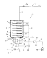
1 is a schematic view showing an ultrasonic cleaner 1 of an embodiment of the present invention, and a part thereof is shown in cross section.
The ultrasonic cleaner 1 of the present embodiment includes a
The object to be cleaned is not particularly limited, but is, for example, a medical instrument such as a forceps. In the
The
The
The
The water supply means (4) supplies water into the washing tub (2) through the water feed line (13). A water supply valve (14) is provided in the water supply line (13). It is possible to supply water into the
A
The drain means 5 discharges the water from the
The chemical liquid supply means 6 supplies the chemical liquid from the
The circulation means 7 circulates and supplies the liquid from the lower portion of the
The heating means 8 is means for heating the stored liquid in the
In addition, a
The
The control means is a controller connected to the respective means (4 to 8) and the ultrasonic oscillator (10), the liquid level detector (15), the temperature sensor (25) and the like. Specifically, the
First, as a premise, in the ultrasonic cleaner 1 of the present embodiment, the operation mode of the oscillation by the
(a) Single oscillation mode = oscillation mode of short-wave (output and frequency is constant). Generates strong cavitation, eliminating stubborn contamination.
(b) Dual oscillation mode = oscillation mode of two frequencies (two waves in close proximity). Suppresses the rectification of cavitation and propagates the ultrasonic waves to the far side.
(c) FM oscillation mode = oscillation mode with frequency modulation (ie FM modulation). The stationary wave position is moved to reduce irregularities in cleaning.
(d) Pulse oscillation mode = an oscillation mode in which a short-circuited frequency (typically one cycle) is intermittently oscillated. This is effective for accelerating the degassing to reduce the attenuation of the ultrasonic waves.
(e) AM oscillation mode = oscillation mode using amplitude modulation (output change) (i.e., AM modulation wave).
(f) FM / AM oscillation mode = oscillation mode with frequency modulation and amplitude modulation (ie simultaneous change of frequency and output).
(g) Multi-oscillation mode = oscillation mode in which three frequencies (for example, 28 kHz, 45 kHz, and 100 kHz) are sequentially repeated.
(h) DynaShock Modulation oscillation mode = oscillation mode that controls the power ratio of ultrasonic waves occurring at two frequencies.
In either case, it is preferable that the control means controls the
Hereinafter, an example of a method of operating the ultrasonic cleaner 1 of the present embodiment will be described in detail.
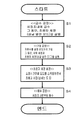
Fig. 2 is a flow chart showing an example of the operation method of the ultrasonic cleaner 1 of the present embodiment. Fig. 3 is a flowchart showing an example of the ultrasonic cleaning process in Fig.
In the initial state, the
«Watering process S1»
In the water supplying step S1, water is stored in the
In the water supply step S1, the
In the water supply step S1, the circulation means 7 may be operated during water supply (that is, after a certain amount of water is collected). For example, when the circulation start water level (the water level exceeding the liquid storage portion 12) or more is reached, the
In the water supply step S1, the
&Quot; Heating step S2 &
In the heating step S2, the heating means 8 heats the stored liquid in the
In the heating step S2, the circulation means 7 may be operated in the same manner as the water supply step (S1). When the
During the heating step S2, the
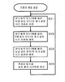
&Quot; Ultrasonic cleaning process S3 "
In the ultrasonic cleaning step S3, as shown in Fig. 3, the object to be cleaned is subjected to ultrasonic cleaning while switching the operation mode. As described above, in this embodiment, the operation mode includes the frequency (Hz) and / or the output (W) by a desired value in addition to the oscillation mode of the ultrasonic wave (the oscillation mode type as in the above- . It is not necessary to individually set the oscillation mode, the frequency and the output of the ultrasonic wave for each operation mode individually. As described above, for example, when the oscillation mode is set, the frequency and / or the output are automatically set . It is also preferable to change at least one of the oscillation mode, the frequency and the output of the ultrasonic wave during the transition from the heating step S2 to the ultrasonic cleaning step S3 when the
In this embodiment, the ultrasonic cleaning S31 of the first set time (for example, 30 seconds) in at least the first operation mode (for example, dual oscillation mode, 800W) and the second operation mode The ultrasonic cleaning S32 of the second set time (for example, 29 seconds) in the mode (for example, mode 800W) is performed. It is also possible to add ultrasonic cleaning S33 (or ultrasonic cleaning of the fourth set time in the fourth operation mode) of the third set time in the third operation mode (for example, the single oscillation mode) The ultrasonic cleaning operation in the set number of operation modes can be executed sequentially in total. Then, when the operation mode of the set number is almost executed, the ultrasonic cleaning is performed again in order from the ultrasonic cleaning S31 of the first set time in the first operation mode.
In the ultrasonic cleaning operation (including the ultrasonic cleaning step S3 as well as the water supply step S1 or the heating step S2, when the
In addition, the adjacent operation modes (that is, the operation modes to be performed and the operation modes immediately thereafter) in the same ultrasonic cleaning operation may be the same oscillation mode (that is, the same mode type) if they have different frequencies or outputs. For example, if the first operation mode is a dual oscillation mode, the second operation mode is a single oscillation mode, and the third operation mode is a single oscillation mode (only frequency and / or output is different) as the second operation mode .
As described above, at least one of an oscillation mode of an ultrasonic wave, a frequency (a modulation method in the case of FM modulation) and an output (a modulation method in the case of AM modulation) are set to be different between the front and rear operation modes.
Either way, in the ultrasonic cleaning step S3, the ultrasonic cleaning is repeated while switching a plurality of operation modes in time. In this embodiment, every time the operation modes (that is, the operation mode of the set number) (For example, set at 1 to 5 seconds, and in this embodiment, 1 second). That is, in Fig. 3, after the ultrasonic cleaning S32 of the second set time in the second operation mode (when the ultrasonic cleaning S33 of the third set time in the third operation mode is performed, etc.), the ultrasonic oscillator 10 ) Is stopped for the set idle time, and then returns to the first first oscillation mode.
Thus, in the ultrasonic cleaner 1 of the present embodiment, the
However, the stop of the ultrasonic vibration (the temporary interruption of the ultrasonic wave oscillation during the ultrasonic wave oscillation) is not limited to every time when the plurality of operation modes are almost finished, At the time of switching from the first operation mode to the second departure operation mode, and / or at the time of switching from the second operation mode to the third operation mode). Alternatively, during the oscillation in the predetermined operation mode, the
Either way, as shown in FIG. 2, after the ultrasonic cleaning is performed while switching the operation mode for a predetermined time (for example, 10 minutes), the
«Drainage process S4»
In the drainage step S4, the drainage means 5 discharges the stored liquid in the
As described above, in the ultrasonic cleaner 1 of the present embodiment, the oscillation mode by the
For example, a controller (for example, a touch panel) is also connected to the controller, and the presence or absence of ultrasonic oscillation in the water supply step S1 or the heating step S2 can be set prior to the start of operation. At this time, when ultrasonic oscillation is performed, one or more of the oscillation mode, the output, and the frequency may be changed. In the ultrasonic cleaning step S3, the output or frequency for each operation mode can be set by the type of the oscillation mode in each operation mode in Fig. This makes it possible to perform optimum cleaning in accordance with the object to be cleaned.
The ultrasonic cleaner 1 of the present invention is not limited to the configuration (including the control) of the embodiment described above, and can be changed appropriately. More particularly, the present invention relates to an ultrasonic oscillator (10) for operating the ultrasonic oscillator (9), an ultrasonic oscillator (9) provided in the cleaning tank (2) And control means for ultrasonically cleaning the object to be cleaned by controlling the
For example, in the above embodiment, the shower cleaning from the cleaning
In the above-described embodiment, the opening of the front surface (and the back surface) of the
Further, in the above embodiment, a blower may be further provided to dry the object to be cleaned after the ultrasonic cleaning. In this case, the wet object to be cleaned after cleaning is dried by hot air supplied to the
In the above embodiment, the object to be cleaned is taken in and out of the net shelf in the
1: ultrasonic cleaner 2: cleaning tank (2a: inclined surface)
3: cleaning nozzle (jetting part) 4: water supply means
5: drainage means 6: chemical liquid supply means
7: circulation means 8: heating means
9: Ultrasonic oscillator 10: Ultrasonic oscillator
11: support member 12: liquid reservoir
13: Water line 14: Water supply valve
15: liquid level detector 16:
17: drain valve 18: chemical tank
19: liquid level 20: chemical pump
21: Circulation piping 22: Circulation pump
23: check valve 24: heater
25: Temperature sensor
Claims (6)
Wherein the controller controls ultrasonic cleaning of the object to be cleaned while switching the operation mode of the ultrasonic oscillator.
Wherein the switching of the operating mode of the ultrasonic oscillator includes switching of the oscillation mode by the ultrasonic oscillator.
Wherein the controller stops the ultrasonic oscillator for a set idle time during the ultrasonic oscillation by the ultrasonic oscillator.
The ultrasonic oscillation by the ultrasonic oscillator repeats while switching a plurality of operation modes to time. However, when the plurality of operation modes are almost terminated, or at predetermined times during switching of the respective operation modes or in a predetermined operation mode And stops the ultrasonic oscillator by the set rest time during the oscillation of the ultrasonic oscillator.
Further comprising a circulation means for circulating and supplying the liquid to the object to be cleaned in the cleaning tank and the liquid below the cleaning tank,
It is possible to sequentially carry out the water supply step into the cleaning tank, the heating step of the stored liquid in the cleaning tank, the ultrasonic cleaning step of the object to be cleaned in the cleaning tank, and the drainage process to the outside of the cleaning tank,
The circulation means is operated in at least the heating process during the water feed process and the heating process, and the ultrasonic vibrator is operated,
And changing an oscillation mode, frequency and an output of the ultrasonic wave in accordance with the transition from the heating step to the ultrasonic cleaning step.
At least in the heating step of the water supply step and the heating step, the ultrasonic vibrator is operated by the single oscillation mode of the single frequency,
In the ultrasonic cleaning process, the ultrasonic oscillator is operated by one or both of a dual oscillation mode using two frequencies and an FM oscillation mode using frequency modulation,
Wherein the output of the single oscillation mode in the heating step is set larger than the output of the dual oscillation mode and the FM oscillation mode in the ultrasonic cleaning step.
Applications Claiming Priority (3)
| Application Number | Priority Date | Filing Date | Title |
|---|---|---|---|
| JP2016133814A JP2018001120A (en) | 2016-07-06 | 2016-07-06 | Ultrasonic cleaner |
| JPJP-P-2016-133814 | 2016-07-06 | ||
| PCT/JP2017/022541 WO2018008377A1 (en) | 2016-07-06 | 2017-06-19 | Ultrasonic cleaner |
Publications (1)
| Publication Number | Publication Date |
|---|---|
| KR20190026538A true KR20190026538A (en) | 2019-03-13 |
Family
ID=60912612
Family Applications (1)
| Application Number | Title | Priority Date | Filing Date |
|---|---|---|---|
| KR1020177031690A KR20190026538A (en) | 2016-07-06 | 2017-06-19 | Ultrasonic Cleaner |
Country Status (4)
| Country | Link |
|---|---|
| JP (1) | JP2018001120A (en) |
| KR (1) | KR20190026538A (en) |
| CN (1) | CN107801382A (en) |
| WO (1) | WO2018008377A1 (en) |
Families Citing this family (4)
| Publication number | Priority date | Publication date | Assignee | Title |
|---|---|---|---|---|
| CN109210983B (en) * | 2018-08-13 | 2020-01-03 | 珠海格力电器股份有限公司 | Descaling method, device, system, controller and storage medium |
| JPWO2021033696A1 (en) * | 2019-08-22 | 2021-02-25 | ||
| JP7265675B6 (en) | 2022-09-16 | 2023-06-23 | パーパス株式会社 | Ultrasonic cleaning control method, program and device |
| CN116000006A (en) * | 2022-11-09 | 2023-04-25 | 浙江佰泰医疗科技有限公司 | Multifunctional ultrasonic cleaner with automatic control function |
Citations (1)
| Publication number | Priority date | Publication date | Assignee | Title |
|---|---|---|---|---|
| WO2008035581A1 (en) | 2006-09-22 | 2008-03-27 | Kaijo Corporation | Ultrasonic cleaning apparatus |
Family Cites Families (11)
| Publication number | Priority date | Publication date | Assignee | Title |
|---|---|---|---|---|
| JP2794438B2 (en) * | 1989-02-16 | 1998-09-03 | 本多電子株式会社 | Cleaning method using cavitation |
| US5218980A (en) * | 1991-10-10 | 1993-06-15 | Evans David H | Ultrasonic dishwasher system |
| JPH05317820A (en) * | 1992-05-25 | 1993-12-03 | Shimada Phys & Chem Ind Co Ltd | Ultrasonic cleaning method and device therefor |
| KR940019363A (en) * | 1993-02-22 | 1994-09-14 | 요시히데 시바노 | Oscillator Oscillation Method in Ultrasonic Cleaning |
| JP3406887B2 (en) * | 2000-03-24 | 2003-05-19 | 三菱電機ビルテクノサービス株式会社 | Filter cleaning equipment |
| JP4159574B2 (en) * | 2005-06-21 | 2008-10-01 | 株式会社カイジョー | Deaeration device and ultrasonic cleaning device using the same |
| WO2010101036A1 (en) * | 2009-03-04 | 2010-09-10 | 日本碍子株式会社 | Ultrasonic cleaning method and ultrasonic cleaning device |
| CN101884984A (en) * | 2009-05-12 | 2010-11-17 | 昆山市超声仪器有限公司 | Medical fully-automatic ultrasonic spray cleaning disinfector |
| CN101884985A (en) * | 2009-05-12 | 2010-11-17 | 昆山市超声仪器有限公司 | Automatic frequency-hopping ultrasonic cleaner |
| JP4826851B2 (en) * | 2009-06-05 | 2011-11-30 | セイコーエプソン株式会社 | Cleaning device |
| JP5594659B2 (en) * | 2010-05-21 | 2014-09-24 | サクラ精機株式会社 | Cleaning method and cleaning apparatus |
-
2016
- 2016-07-06 JP JP2016133814A patent/JP2018001120A/en active Pending
-
2017
- 2017-06-19 WO PCT/JP2017/022541 patent/WO2018008377A1/en active Application Filing
- 2017-06-19 CN CN201780001872.1A patent/CN107801382A/en active Pending
- 2017-06-19 KR KR1020177031690A patent/KR20190026538A/en unknown
Patent Citations (1)
| Publication number | Priority date | Publication date | Assignee | Title |
|---|---|---|---|---|
| WO2008035581A1 (en) | 2006-09-22 | 2008-03-27 | Kaijo Corporation | Ultrasonic cleaning apparatus |
Also Published As
| Publication number | Publication date |
|---|---|
| WO2018008377A1 (en) | 2018-01-11 |
| JP2018001120A (en) | 2018-01-11 |
| CN107801382A (en) | 2018-03-13 |
Similar Documents
| Publication | Publication Date | Title |
|---|---|---|
| KR20190026538A (en) | Ultrasonic Cleaner | |
| US8518188B2 (en) | Method of controlling dishwasher | |
| KR101296777B1 (en) | Clean water storage tank with a steam convection oven | |
| KR20130029646A (en) | Steam convection oven to self-cleaning system | |
| JP2007130037A (en) | Medical instrument washing apparatus and medical instrument washing method | |
| JP6712409B2 (en) | Ultrasonic cleaner | |
| JP2016073908A (en) | Washer | |
| JP6579368B2 (en) | Washing machine | |
| US7998280B2 (en) | Method of controlling dishwasher and dishwasher | |
| JP2016144784A (en) | Washing machine | |
| KR20180127911A (en) | Washer | |
| JP2017023985A (en) | Washer | |
| KR102247957B1 (en) | Household dishwasher | |
| KR20070083137A (en) | A supersonic wave washer | |
| JP7012938B2 (en) | Washing machine | |
| JP2017070882A (en) | Washer | |
| JP2019084502A (en) | Washer and operation method of the same | |
| KR20190051774A (en) | Cleaner | |
| JP2016073909A (en) | Washer | |
| JP6593577B2 (en) | Washing machine | |
| JP6443729B2 (en) | Washing machine | |
| JP7205759B2 (en) | Washing machine | |
| JP5701001B2 (en) | washing machine | |
| KR102481975B1 (en) | Household dishwasher | |
| CN113680773B (en) | Cleaning device and cleaning method for dried salted duck roaster |