KR20180122377A - Position encoder - Google Patents
Position encoder Download PDFInfo
- Publication number
- KR20180122377A KR20180122377A KR1020187028324A KR20187028324A KR20180122377A KR 20180122377 A KR20180122377 A KR 20180122377A KR 1020187028324 A KR1020187028324 A KR 1020187028324A KR 20187028324 A KR20187028324 A KR 20187028324A KR 20180122377 A KR20180122377 A KR 20180122377A
- Authority
- KR
- South Korea
- Prior art keywords
- sensors
- sensor
- linear
- pattern
- machine
- Prior art date
Links
- 230000005291 magnetic effect Effects 0.000 claims abstract description 27
- 238000006073 displacement reaction Methods 0.000 claims abstract description 24
- 230000003287 optical effect Effects 0.000 claims abstract description 20
- 238000000034 method Methods 0.000 claims description 37
- 230000001939 inductive effect Effects 0.000 claims description 15
- 238000005259 measurement Methods 0.000 claims description 14
- 230000033001 locomotion Effects 0.000 claims description 13
- 239000002184 metal Substances 0.000 claims description 7
- 230000008859 change Effects 0.000 claims description 4
- 238000001514 detection method Methods 0.000 abstract description 4
- 238000012545 processing Methods 0.000 description 22
- 238000010586 diagram Methods 0.000 description 9
- 239000000463 material Substances 0.000 description 9
- 230000003068 static effect Effects 0.000 description 8
- 238000013461 design Methods 0.000 description 4
- 238000005516 engineering process Methods 0.000 description 4
- 238000004519 manufacturing process Methods 0.000 description 4
- 230000008569 process Effects 0.000 description 4
- 238000004364 calculation method Methods 0.000 description 3
- 230000001965 increasing effect Effects 0.000 description 3
- 230000035945 sensitivity Effects 0.000 description 3
- 238000013459 approach Methods 0.000 description 2
- 238000004891 communication Methods 0.000 description 2
- 238000012937 correction Methods 0.000 description 2
- 238000003754 machining Methods 0.000 description 2
- 238000012986 modification Methods 0.000 description 2
- 230000004048 modification Effects 0.000 description 2
- 230000000737 periodic effect Effects 0.000 description 2
- 239000004065 semiconductor Substances 0.000 description 2
- 230000007704 transition Effects 0.000 description 2
- ARXHIJMGSIYYRZ-UHFFFAOYSA-N 1,2,4-trichloro-3-(3,4-dichlorophenyl)benzene Chemical compound C1=C(Cl)C(Cl)=CC=C1C1=C(Cl)C=CC(Cl)=C1Cl ARXHIJMGSIYYRZ-UHFFFAOYSA-N 0.000 description 1
- SUOAMBOBSWRMNQ-UHFFFAOYSA-N 1,2,5-trichloro-3-(2,4-dichlorophenyl)benzene Chemical compound ClC1=CC(Cl)=CC=C1C1=CC(Cl)=CC(Cl)=C1Cl SUOAMBOBSWRMNQ-UHFFFAOYSA-N 0.000 description 1
- GOFFZTAPOOICFT-UHFFFAOYSA-N 1,3,5-trichloro-2-(2,3-dichlorophenyl)benzene Chemical compound ClC1=CC(Cl)=CC(Cl)=C1C1=CC=CC(Cl)=C1Cl GOFFZTAPOOICFT-UHFFFAOYSA-N 0.000 description 1
- HCWZEPKLWVAEOV-UHFFFAOYSA-N 2,2',5,5'-tetrachlorobiphenyl Chemical compound ClC1=CC=C(Cl)C(C=2C(=CC=C(Cl)C=2)Cl)=C1 HCWZEPKLWVAEOV-UHFFFAOYSA-N 0.000 description 1
- IUTPYMGCWINGEY-UHFFFAOYSA-N 2,3',4,4',5-Pentachlorobiphenyl Chemical compound C1=C(Cl)C(Cl)=CC=C1C1=CC(Cl)=C(Cl)C=C1Cl IUTPYMGCWINGEY-UHFFFAOYSA-N 0.000 description 1
- 230000005355 Hall effect Effects 0.000 description 1
- 238000003491 array Methods 0.000 description 1
- 230000033228 biological regulation Effects 0.000 description 1
- 230000007423 decrease Effects 0.000 description 1
- 230000001419 dependent effect Effects 0.000 description 1
- 239000006185 dispersion Substances 0.000 description 1
- 239000000428 dust Substances 0.000 description 1
- 230000000694 effects Effects 0.000 description 1
- 239000003344 environmental pollutant Substances 0.000 description 1
- 238000010438 heat treatment Methods 0.000 description 1
- 230000001771 impaired effect Effects 0.000 description 1
- 231100000719 pollutant Toxicity 0.000 description 1
- 238000007639 printing Methods 0.000 description 1
- 230000008054 signal transmission Effects 0.000 description 1
- 238000003860 storage Methods 0.000 description 1
- 238000012360 testing method Methods 0.000 description 1
- 238000004804 winding Methods 0.000 description 1
Images


Classifications
-
- G—PHYSICS
- G01—MEASURING; TESTING
- G01D—MEASURING NOT SPECIALLY ADAPTED FOR A SPECIFIC VARIABLE; ARRANGEMENTS FOR MEASURING TWO OR MORE VARIABLES NOT COVERED IN A SINGLE OTHER SUBCLASS; TARIFF METERING APPARATUS; MEASURING OR TESTING NOT OTHERWISE PROVIDED FOR
- G01D5/00—Mechanical means for transferring the output of a sensing member; Means for converting the output of a sensing member to another variable where the form or nature of the sensing member does not constrain the means for converting; Transducers not specially adapted for a specific variable
- G01D5/26—Mechanical means for transferring the output of a sensing member; Means for converting the output of a sensing member to another variable where the form or nature of the sensing member does not constrain the means for converting; Transducers not specially adapted for a specific variable characterised by optical transfer means, i.e. using infrared, visible, or ultraviolet light
- G01D5/32—Mechanical means for transferring the output of a sensing member; Means for converting the output of a sensing member to another variable where the form or nature of the sensing member does not constrain the means for converting; Transducers not specially adapted for a specific variable characterised by optical transfer means, i.e. using infrared, visible, or ultraviolet light with attenuation or whole or partial obturation of beams of light
- G01D5/34—Mechanical means for transferring the output of a sensing member; Means for converting the output of a sensing member to another variable where the form or nature of the sensing member does not constrain the means for converting; Transducers not specially adapted for a specific variable characterised by optical transfer means, i.e. using infrared, visible, or ultraviolet light with attenuation or whole or partial obturation of beams of light the beams of light being detected by photocells
- G01D5/347—Mechanical means for transferring the output of a sensing member; Means for converting the output of a sensing member to another variable where the form or nature of the sensing member does not constrain the means for converting; Transducers not specially adapted for a specific variable characterised by optical transfer means, i.e. using infrared, visible, or ultraviolet light with attenuation or whole or partial obturation of beams of light the beams of light being detected by photocells using displacement encoding scales
- G01D5/34746—Linear encoders
-
- G—PHYSICS
- G01—MEASURING; TESTING
- G01D—MEASURING NOT SPECIALLY ADAPTED FOR A SPECIFIC VARIABLE; ARRANGEMENTS FOR MEASURING TWO OR MORE VARIABLES NOT COVERED IN A SINGLE OTHER SUBCLASS; TARIFF METERING APPARATUS; MEASURING OR TESTING NOT OTHERWISE PROVIDED FOR
- G01D5/00—Mechanical means for transferring the output of a sensing member; Means for converting the output of a sensing member to another variable where the form or nature of the sensing member does not constrain the means for converting; Transducers not specially adapted for a specific variable
- G01D5/12—Mechanical means for transferring the output of a sensing member; Means for converting the output of a sensing member to another variable where the form or nature of the sensing member does not constrain the means for converting; Transducers not specially adapted for a specific variable using electric or magnetic means
- G01D5/244—Mechanical means for transferring the output of a sensing member; Means for converting the output of a sensing member to another variable where the form or nature of the sensing member does not constrain the means for converting; Transducers not specially adapted for a specific variable using electric or magnetic means influencing characteristics of pulses or pulse trains; generating pulses or pulse trains
- G01D5/249—Mechanical means for transferring the output of a sensing member; Means for converting the output of a sensing member to another variable where the form or nature of the sensing member does not constrain the means for converting; Transducers not specially adapted for a specific variable using electric or magnetic means influencing characteristics of pulses or pulse trains; generating pulses or pulse trains using pulse code
- G01D5/2492—Pulse stream
-
- H—ELECTRICITY
- H02—GENERATION; CONVERSION OR DISTRIBUTION OF ELECTRIC POWER
- H02K—DYNAMO-ELECTRIC MACHINES
- H02K11/00—Structural association of dynamo-electric machines with electric components or with devices for shielding, monitoring or protection
- H02K11/20—Structural association of dynamo-electric machines with electric components or with devices for shielding, monitoring or protection for measuring, monitoring, testing, protecting or switching
- H02K11/21—Devices for sensing speed or position, or actuated thereby
-
- H—ELECTRICITY
- H02—GENERATION; CONVERSION OR DISTRIBUTION OF ELECTRIC POWER
- H02K—DYNAMO-ELECTRIC MACHINES
- H02K41/00—Propulsion systems in which a rigid body is moved along a path due to dynamo-electric interaction between the body and a magnetic field travelling along the path
- H02K41/02—Linear motors; Sectional motors
Abstract
선형 엔코더는 고정부와 이동부를 가지며, 변위의 선형 범위를 따라서 고정부와 이동부 사이의 상대적 변위를 측정하고 암호화한다. 엔코더는 설정된 패턴으로 부분들 중 한 부분 상에 배열된 다수의 기계 감지 가능한 요소; 및 전체 선형 범위를 따라서 다른 부분을 따라 배열된 다수의 균일하게 위치된 센서를 포함하여, 그에 의하여 변위를 측정하고 암호화한다. 엔코더는 절대치 엔코더일 수 있으며, 자기 또는 광학 또는 임의의 다른 종류의 감지를 기반으로 할 수 있다.Linear encoders have fixed and moving parts and measure and encode the relative displacement between the fixed part and the moving part along the linear range of the displacement. The encoder includes a plurality of machine-sensible elements arranged on one of the parts in a set pattern; And a plurality of uniformly positioned sensors arranged along different portions along the entire linear range, thereby measuring and encrypting the displacement. The encoder may be an absolute encoder and may be based on magnetic or optical or any other type of detection.
Description
본 발명은, 포지션 엔코더에 관한 것으로, 보다 상세하게 그러나 배타적이지 않게는, 선형 모터와 같은 모터와 관련하여 사용된 엔코더 및 자기 절대치 선형 엔코더에 대한 적용에 관한 것이다.The present invention relates to position encoders and, more particularly but not exclusively, to the application to encoders and magnetic absolute linear encoders used in connection with motors such as linear motors.
공작 기계 및 산업용 로봇을 위한 선형 서보 모터와 같은 장치에서, 가공 정밀도를 초과하기 위해서는 위치 결정 정밀도가 요구된다. 반도체 칩 제조와 같은 적용을 위한 가공 기술은 계속해서 증가하는 가공 정밀도가 필요하며, 결과적으로 요구되는 위치 결정 정밀도 또한 증가하고 있다. 고정밀도의 위치 결정을 수행하기 위하여 정밀한 위치 측정 장치가 필요하며, 선형 엔코더가 제공되어 위치 결정 요구 조건을 충족시킨다.In apparatuses such as linear servomotors for machine tools and industrial robots, positioning accuracy is required to exceed machining accuracy. Processing techniques for applications such as semiconductor chip fabrication continue to require increased processing accuracy, and as a result, required positioning accuracy is also increasing. Accurate positioning devices are required to perform high-precision positioning, and linear encoders are provided to meet positioning requirements.
선형 엔코더는 위치를 암호화하는 스케일 또는 패턴과 한 조를 이루는 센서, 트랜스듀서 또는 변환기 또는 판독-헤드이다. 암호화된 위치를 아날로그 또는 디지털 신호로 변환하기 위하여 센서는 스케일을 판독하고, 이 신호는 그후 디지털 판독 헤드(DRO), 드라이브 또는 모션 컨트롤러에 의하여 위치로 복호화될 수 있다. 일반적으로, 스케일은 측정될 궤적의 전체 길이에 걸쳐 연장되며, 센서는 위치를 측정하는 스케일 위로 이동한다. 대부분의 사용 가능한 선형 엔코더는 고정될 DRO 헤드에 이동 요소를 제공하고, 전기 케이블에 의하여 드라이브 또는 모션 컨트롤러로 전송되는 디지털 또는 아날로그 신호를 제공한다. 동일한 전기 케이블 또한 DRO 처리 전자 장치에 전기 에너지를 공급하기 위하여 사용된다. 따라서 전기 케이블은 한 말단 상에서 드라이브에 고정되고 그의 다른 말단에서는 이동 요소와 함께 움직인다. 이동 요소는 흔히 고속 모션 사이클을 실행하며, 따라서 이동 케이블은 시스템 고장의 주요 요인이다.Linear encoders are sensors, transducers or transducers, or read-heads, that form a set of scales or patterns that encode positions. To convert the encrypted location to an analog or digital signal, the sensor reads the scale, which can then be decoded to a location by a digital read head (DRO), drive, or motion controller. Generally, the scale extends over the entire length of the locus to be measured, and the sensor moves over a scale that measures the position. Most of the available linear encoders provide a moving element to the DRO head to be fixed and provide a digital or analog signal that is sent to the drive or motion controller by an electrical cable. The same electrical cable is also used to supply electrical energy to the DRO processing electronics. Thus, the electrical cable is fixed to the drive at one end and moves with the moving element at its other end. Moving elements often perform high-speed motion cycles, and therefore mobile cables are a major factor in system failures.
엔코더는 증분 또는 절대치 엔코더일 수 있다. 증분 엔코더는 전원을 켰을 때 증분 엔코더의 초기 위치와 관하여 이동을 감지할 수 있는 반면에, 절대치 엔코더는 실제 위치를 측정할 수 있다. 선형 엔코더 기술은, 예를 들어 광학, 자기, 인덕티브, 정전 용량형 및 와전류 감지를 기반으로 할 수 있다. 감지될 요소는 광학 스케일, 자기 스케일, 인덕티브 스케일, 정전 용량형 스케일 및 코일 감지시 와전류를 유도할 수 있는 스케일을 포함하는, 감지 요소에 의해 감지될 수 있는 것으로 구성된 스케일로서 배열된다. 미국 특허 제6,492,911호 및 제7,126,495 호는 정전 용량형 선형 엔코더를 설명하고 있다. 전자의 경우, 도 32는 고정 스케일을 보여주고 있으며, 도 33b는 형상을 제공하고 있다. 인용 기술의 정전 용량형 엔코더는 아날로그 신호 패턴을 제공한다. 선형 엔코더는, 예를 들어 계측 기기, 모션 시스템과 고정밀 가공 공구 및 디지털 캘리퍼와 좌표 측정 기계에서 스테이지, CNC 밀 및 산업용 로봇에 이르는, 그리고 제조 갠트리 테이블에서 고정밀 반도체 노광 장치에 이르는 제조 장비에 사용된다.The encoder may be an incremental or absolute encoder. The incremental encoder can detect movement with respect to the initial position of the incremental encoder when the power is turned on, while the absolute encoder can measure the actual position. Linear encoder technology can be based, for example, on optical, magnetic, inductive, capacitive and eddy current sensing. The element to be sensed is arranged as a scale that can be sensed by the sensing element, including an optical scale, a magnetic scale, an inductive scale, a capacitive scale, and a scale capable of inducing eddy currents during coil sensing. U.S. Patent Nos. 6,492,911 and 7,126,495 describe capacitive linear encoders. In the former case, FIG. 32 shows the fixed scale and FIG. 33B provides the shape. A capacitive encoder of the cited technology provides an analog signal pattern. Linear encoders are used, for example, in manufacturing equipment ranging from measuring instruments, motion systems and high precision machining tools and digital calipers and coordinate measuring machines to stages, CNC mills and industrial robots, and from manufacturing gantry tables to high precision semiconductor exposures .
자기 엔코더는 증분 원리를 기반으로 구축될 수 있지만 일반적으로 분해능과 정확도에 관해서는 단점을 갖는다. 자기장은 거리에 따라 감소하기 때문에 자기 센서는 패턴의 주기보다 작은 거리에 또는 적어도 동일 범위 내에 위치되어야 한다. 자기 센서를 정적 자기 요소에 매우 가깝게 위치시키는 것은 정밀하고 고가의 기계적 설계를 필요로 한다. 따라서, 주기 길이 및 주기의 수는 달성 가능한 기계적 정밀도에 의해 제한된다.Magnetic encoders can be built on the basis of incremental principles, but they generally have drawbacks in terms of resolution and accuracy. Since the magnetic field decreases with distance, the magnetic sensor must be located at a distance less than, or at least within the same range as, the period of the pattern. Placing the magnetic sensor very close to the static magnetic element requires a precise and expensive mechanical design. Thus, the number of cycles length and number of cycles is limited by achievable mechanical precision.
회전식 및 선형 위치 결정 엔코딩 장치 모두 사용할 수 있다.Both rotary and linear positioning encoding devices are available.
2008년 5월 28일 출원된 Villaret 등의 미국 특허 제8,492,704호는 제1 부재의 단일 트랙 상에서 움직이는 기계 감지 가능한 요소의 패턴을 이용함으로써 제2 부재에 대한 제1 부재의 위치를 정확하게 나타내기 위한 엔코더 및 방법을 개시하고 있으며; 기계 감지 가능한 요소들은 제1 부재의 트랙 상의 연속적인 증분 회전부에 위치하며 각각은 "0" 및 "1"의 이진값 중 하나 및 다수의 "n" 개의 센서를 나타낸다. 여기서, "n"은 제1 부재의 트랙에 근접한 제2 부재 상의 다수의 이격된 위치에서 제2 부재에 의해 지지되고 제1 부재의 기계 감지 가능한 요소와 정렬 가능한 "3"보다 크다. 따라서, 각 센서는 각 기계 감지 가능한 요소의 이진값을 감지하며, 여기서 센서는 이 이진값으로 센서와 정렬된 기계 감지 요소의 이진값에 대응하는 출력을 생성하도록 정렬되고, 그에 의하여 모든 센서의 출력은 제2 부재에 대한 제1 부재의 위치를 식별하는 "n" 비트의 이진 코드, 바람직하게는 그레이 코드를 구성한다. 따라서 도 3은 선형 엔코더에 관한 것이다. 그레이 코드를 형성하는 기계 감지 가능한 요소는 정적이며, 균일하게 이격된 센서들은 이동부 상에 있다. 기계 감지 가능한 부분들은 사실상 로터 상의 검출 가능한 요소들이며, 검출 가능한 요소들은 직선화되어 로터 형태와 동일한 정확도를 위하여, 그러나 로터의 원주에 의하여 이루어진 360도 원으로 제한된 거리를 위하여 절대 위치 측정을 제공한다.United States Patent No. 8,492,704, filed May 28, 2008, filed on August 28, 2008, discloses an encoder for accurately indicating the position of a first member with respect to a second member by utilizing a pattern of a machine-sensible element moving on a single track of the first member. And methods are disclosed; The machine-sensible elements are located in successive incremental rotations on the track of the first member, each representing one of a binary value of "0" and "1 " Where "n" is greater than "3" that is supported by the second member at a plurality of spaced apart locations on the second member proximate to the track of the first member and alignable with the machine-sensible element of the first member. Thus, each sensor senses the binary value of each machine-sensible element, wherein the sensor is arranged to produce an output corresponding to the binary value of the mechanical sensing element aligned with the sensor with this binary value, whereby the output Quot; n "bit binary code, preferably a gray code, identifying the position of the first member relative to the second member. Thus, Figure 3 relates to a linear encoder. The machine-sensible elements forming the gray code are static, and the uniformly spaced sensors are on the moving part. The machine-sensible parts are virtually detectable elements on the rotor, the detectable elements being straightened to provide absolute positioning for the same accuracy as the rotor shape, but for a limited distance to the 360 degree circle made by the circumference of the rotor.
인코딩 길이는 모든 측정 가능한 거리에 걸쳐 센서에 구별할 수 있는 신호를 줄 필요에 의하여 제한된다. 신호는 특정 적용이 요구하는 분해능 수준으로 구별 가능할 필요가 있다. 동일한 정확도를 위하여 길이를 늘리는 것은 상당한 비용 증가를 수반한다. 검출 가능한 패턴의 제2 트랙 또는 패턴의 반복 주기가 필요할 수 있거나, 접속부들은 훨씬 더 많은 수의 비트를 갖는 측정 신호를 수반할 수 있다.The encoding length is limited by the need to give a signal that can be distinguished to the sensor over all measurable distances. The signal needs to be distinguishable by the level of resolution required by a particular application. Increasing the length for the same accuracy involves a significant cost increase. A repetition period of the second track or pattern of the detectable pattern may be required or the connections may involve a measurement signal having a much greater number of bits.
센서가 이동부 상에 위치되기 때문에 공지된 기술은 센서에 전류를 공급하고 센서로부터 신호를 얻기 위해 이동 케이블을 필요로 한다. 고가의 부품이고 비교적 높은 고장율 또는 파손 확률을 갖는 특별히 설계된 이동 케이블이 요구된다. 케이블은 또한 진동 및 속도의 다른 섭동에 대해서도 책임을 질 수 있다. 케이블 체인은 움직임의 매끄러움에 영향을 미칠 수 있으며, 매끄러움은 균일한 잉크층이 침착될 필요가 있는 인쇄와 같은 적용에 특히 중요하다.Because the sensor is located on a moving part, a known technique requires a moving cable to supply current to the sensor and to obtain a signal from the sensor. A specially designed mobile cable is required which is a costly component and has a relatively high failure rate or failure probability. Cables can also be responsible for other perturbations of vibration and speed. Cable chains can affect the smoothness of movement, and smoothness is particularly important for applications such as printing where a uniform ink layer needs to be deposited.
선행 기술의 많은 부분은 스케일링을 위하여 2개의 트랙, 즉 저분해능으로 절대 위치를 제공하는 제1 트랙과 고분해능 트랙의 주기 내에서 고분해능 위치를 제공하는 제2 트랙을 갖고 있다. 회전 시스템을 교시하는, 위에서 언급된 미국 특허 제8,492,704호는 단일 트랙을 갖고 있지만, 회전의 경우에서는 전체 원주의 제한된 길이는 위치 결정이 주기 간격으로 반복되도록 한다. 그러나 선형식 경우와 같이 자연스러운 주기가 없는 경우 절대 위치 또한 필요하다.Much of the prior art has two tracks for scaling: a first track that provides an absolute position at low resolution and a second track that provides a high resolution position within the period of the high-resolution track. The aforementioned U.S. Patent No. 8,492,704, which teaches a rotating system, has a single track, but in the case of rotation, the limited length of the entire circumference allows the positioning to be repeated at periodic intervals. However, if there is no natural cycle as in the case of linear form, absolute position is also necessary.
Chitayat에 의한 미국특허 제5,907,200호는 이동 경로를 따라 분포된 어드레스 가능한 홀 센서 및 홀 센서에 근접한 경로를 따라 슬라이딩하는 이동 요소에 고정된 등거리의 자석들의 세트를 개시하고 있다. 각 홀 센서 신호는 그후 이동 요소의 위치 범위 내에서 제1 값에서 제2 값으로 천이된다. 절대 위치는 센서 어드레스와 센서의 아날로그 또는 디지털 값으로부터 계산된다. 각 쌍의 센서에 대해 하나의 위치 전이 범위가 있다. 하나의 전위 범위는 두 개의 홀 센서 사이의 거리로 정의된다. 따라서 고분해능 위치 값의 계산은 홀 센서 측정의 정밀도에 의하여 한정된다. 따라서, 예를 들어 홀 센서 신호가 10 비트 아날로그 대 디지털 장치로 평가된다면, 그러면 최대 분해능은 2 개의 자석 사이의 거리의 1/1024와 같을 수 있다.U.S. Patent No. 5,907,200 to Chitayat discloses an addressable Hall sensor distributed along a travel path and a set of equidistant magnets fixed to a moving element sliding along a path close to the Hall sensor. Each hall sensor signal is then transitioned from a first value to a second value within the position range of the moving element. The absolute position is calculated from the sensor address and the analog or digital value of the sensor. There is one position transition range for each pair of sensors. One potential range is defined as the distance between two Hall sensors. Therefore, the calculation of the high resolution position value is limited by the precision of the hall sensor measurement. Thus, for example, if the Hall sensor signal is evaluated as a 10-bit analog-to-digital device, then the maximum resolution may be equal to 1/1024 of the distance between the two magnets.
본 발명의 목적은 정적 요소 상에 위치된, 상당히 감소된 개수의 감지 요소로 고분해능 위치 정보를 생성할 수 있는, 케이블이 없는 절대치 엔코더를 제공하는 것이다.It is an object of the present invention to provide a cableless absolute encoder capable of generating high resolution position information with a significantly reduced number of sensing elements located on static elements.
본 발명은 독점적이지는 않지만, 대체로 실시예가 전체 선형 경로를 따라 검출기를 제공함으로써 케이블을 이동시키는 필요성을 방지하는 선형 엔코더에 관한 것이다. 수동 소자, 즉 패턴은 검출기로 덮힌 경로의 전체 길이를 따라 검출기에 대하여 이동한다. 검출기는 개별 또는 그룹 어드레싱에 의해 구별될 수 있으며 패턴의 그리고 따라서 전체 궤적을 따른 임의의 지점에서 이동부의 변위를 복호화할 수 있다.The present invention is not exclusive, but generally relates to a linear encoder that prevents the need for the embodiment to move the cable by providing a detector along the entire linear path. The passive element, i. E. The pattern, moves with respect to the detector along the entire length of the path covered by the detector. The detector can be distinguished by individual or group addressing and can decode the displacement of the moving part at any point along the pattern and thus along the entire trajectory.
실시예에서, 경로는 선형이지만, 본 발명은 임의의 경로 형상을 위하여 더욱 일반적으로 적용 가능하다. 예를 들어, 원형 경로가 회전 엔코더를 위하여 사용될 수 있으며, 이 경우 본 실시예는 직접 구동 모터에서 흔히 보여지는 것과 같은 큰 직경의 경우에 특히 적용 가능하다.In the embodiment, the path is linear, but the present invention is more generally applicable for any path shape. For example, a circular path may be used for the rotary encoder, in which case this embodiment is particularly applicable in the case of large diameters as is common in direct drive motors.
본 실시예의 배열에서, 센서의 정렬은 경로를 따라 제공된다. 이동 요소의 주어진 위치에 대해, 제1의 다수의 센서가 기계 감지 가능한 요소와 근접하고 따라서 활성화되며, 나머지 센서는 기계 감지 가능한 요소와 근접하지 않으며 비활성이다. 따라서, 이동 요소의 임의의 주어진 위치에서, 일부 센서는 활성이고 일부 센서는 비활성이다. 이는 기계 감지 가능한 요소들이 경로를 따라 놓여지고 센서가 항상 한 요소 또는 다른 요소에 근접함에 따라 모든 센서가 항상 활성화되어 있는, Villaret에 대한 미국 특허 제 8,492,704 호의 선행 기술과 대조를 이룬다.In the arrangement of this embodiment, alignment of the sensors is provided along the path. For a given position of the mobile element, a first plurality of sensors are proximate and thus activated, the machine-sensible element, and the remaining sensors are non-proximate and inactive to the machine-sensible element. Thus, at any given position of the moving element, some sensors are active and some sensors are inactive. This contrasts with the prior art of U.S. Patent No. 8,492,704 to Villaret, in which all sensors are always active as the machine-sensible elements are placed along the path and the sensor always approaches one element or another.
본 발명의 일부 실시예의 측면에 따르면, 고정부와 이동부를 갖는 선형 위치 측정 장치를 위한 것으로서, 제1 이동 말단 위치와 제2 이동 말단 위치 사이의 선형 이동 범위를 따라서 상기 고정부와 상기 이동부 사이의 상대적인 변위를 측정하고 암호화하도록 설계된 선형 엔코더가 제공되며, 엔코더는 길이를 따라서 변화하는 특성을 포함하는 설정된 패턴으로 상기 부분의 제1 부분 상에 배열된 다수의 기계 감지 가능한 요소 및 상기 제1 이동 말단 위치와 상기 제2 이동 말단 위치 사이의 상기 선형 이동 범위 전체를 따라서 상기 부분의 제2 부분을 따라 배열되며, 그로 인하여 상기 변위를 측정하고 암호화하는, 균일하게 위치된 다수의 센서를 포함한다.According to an aspect of some embodiments of the present invention there is provided a linear position measuring device having a stationary portion and a moving portion, the linear position measuring device having a fixed portion and a moving portion, Wherein the encoder comprises a plurality of machine-sensible elements arranged on a first portion of the portion in a set pattern comprising characteristics that vary along a length, and a plurality of machine- And a plurality of uniformly positioned sensors arranged along a second portion of the portion along the entire linear travel range between the end position and the second moving end position, thereby measuring and encrypting the displacement.
실시예에서, 상기 제1 부분은 상기 이동부이며, 상기 제2 부분은 상기 정지부이다.In an embodiment, the first portion is the moving portion and the second portion is the stop portion.
실시예에서, 상기 설정 패턴의 길이는 상기 전체 범위보다 짧다.In an embodiment, the length of the setting pattern is shorter than the entire range.
실시예에서, 상기 균일하게 위치된 센서들 각각은 고유 어드레스를 갖는다.In an embodiment, each of the uniformly positioned sensors has a unique address.
실시예에서, 상기 균일하게 위치된 센서들은 광학, 자기, 인덕티브, 정전 용량형, 광전 그리고 와전류 센서로 이루어진 센서 그룹 중 하나의 부재를 포함한다.In an embodiment, the uniformly positioned sensors include a member of one of a group of sensors consisting of optical, magnetic, inductive, capacitive, photoelectric and eddy current sensors.
실시예에서, 상기 기계 감지 가능한 요소는 광학 요소, 자기 요소, 인덕티브 요소, 정전 용량형 요소 그리고 금속계 섭동 요소로 이루어진 그룹 중 하나의 부재를 포함한다.In an embodiment, the machine-sensible element comprises a member of one of the group consisting of an optical element, a magnetic element, an inductive element, a capacitive element and a metal-based perturbation element.
실시예에서, 상기 설정된 패턴은 상기 특성의 변화의 한 사이클을 각각 포함하는 일련의 반복하는 세그먼트들을 한정한다.In an embodiment, the set pattern defines a series of repeating segments each comprising a cycle of the change of characteristics.
실시예에서, 상기 세그먼트들은 상기 균일하게 이격된 설정된 개수의 센서들과 동등한 길이에 걸쳐 펼쳐져 있다.In an embodiment, the segments are spread over a length equal to the uniformly spaced set number of sensors.
실시예에서, 상기 기계 감지 가능한 요소는 제2 변화 특성을 갖는다.In an embodiment, the machine-sensible element has a second variation characteristic.
예시적인 실시예는 상기 길이의 시작을 상기 센서에 나타내기 위하여 상기 패턴의 외부에 위치된 부가적인 기계 감지 가능한 요소를 포함할 수 있다.An exemplary embodiment may include an additional machine-sensible element located outside of the pattern to indicate to the sensor the beginning of the length.
본 발명의 제2 측면에 따르면, 전체 선형 변위 길이에 걸쳐 2개 부분 사이의 상대 변위의 절대 선형 암호화 방법이 제공되며, 본 방법은,According to a second aspect of the present invention there is provided an absolute linear encryption method of relative displacement between two parts over an entire linear displacement length,
상기 전체 변위 길이에 걸쳐 이격된 다수의 센서를 제공하고 상기 패턴을 따르는 걸이에 걸쳐 변화하는 특성을 포함하고 있는, 기계 감지 가능한 요소의 설정된 패턴을 제공하며, 상기 변위 길이에 걸쳐 상기 다수의 센서에 대하여 상기 패턴을 선형적으로 변위시키고 그리고 상기 다수의 센서를 이용하여 상기 변위를 측정하는 것을 포함한다.Providing a plurality of sensors spaced over the entire displacement length and providing a predetermined pattern of machine-sensible elements that includes varying properties across a hook following the pattern, wherein the plurality of sensors Linearly displacing the pattern and measuring the displacement using the plurality of sensors.
실시예에서, 상기 센서들은 상기 변위 길이에 걸쳐 균일하게 분포된다.In an embodiment, the sensors are uniformly distributed over the displacement length.
본 방법은 상기 균일하게 분포된, 설정된 개수의 센서들과 동등한 길이에 걸쳐 연장된 패턴을 연장시키는 것을 포함할 수 있다.The method may include extending the pattern extending over a length equal to the uniformly distributed, set number of sensors.
본 방법은 상기 다수의 균일하게 분포된 센서로 패턴 시작 또는 끝을 나타내기 위하여 상기 패턴의 제1 말단에 부가적인 감지 가능한 요소를 제공하는 것을 포함할 수 있다.The method may include providing an additional sensible element at a first end of the pattern to indicate a pattern start or end with the plurality of uniformly distributed sensors.
실시예에서, 상기 패턴은 선형 모터의 이동부 내에 있으며, 상기 다수의 센서는 상기 선형 모터의 고정부 상에 있다.In an embodiment, the pattern is in a moving portion of a linear motor, and the plurality of sensors are on a fixed portion of the linear motor.
본 방법은 상기 다수의 센서의 각각에 개별 어드레싱을 제공하는 것을 포함할 수 있다.The method may include providing individual addressing to each of the plurality of sensors.
실시예에서, 상기 패턴의 길이는 상기 변위 길이보다 짧다.In an embodiment, the length of the pattern is shorter than the displacement length.
실시예에서, 상기 부가적인 기계 감지 가능한 요소는 상기 설정된 패턴의 제1 기계-감지 가능한 요소의 반복이다. In an embodiment, the additional machine-sensible element is a repetition of the first machine-sensible element of the set pattern.
본 방법은 상기 다수의 센서는 자기 센서, 홀 센서, 광학 센서, 인덕티브 센서 그리고 정전 용량형 센서 중 임의의 것 그리고 이용 가능할 수 있는 임의의 다른 적절한 센서일 수 있다.The method may be any of a number of sensors, magnetic sensors, Hall sensors, optical sensors, inductive sensors and capacitive sensors, and any other suitable sensors that may be available.
본 방법은, 현재 기계 감지 가능한 요소에 인접한 센서를 활성 센서로 검출하고, 상기 활성 센서의 위치를 기초로 제1 절대 저분해능 위치를 계산하며, N 비트의 각각을 상기 활성 센서의 불린(Boolean) 출력 값으로 설정함으로써 다수의 N 비트의 코드를 계산하여, 그로 인하여 상기 코드가 상기 활성 센서 중 하나에 대하여 중간 분해능 위치를 한정하며, 상기 제1 절대 저분해능 위치 값을 상기 제2 상대적 중간 분해능 위치 값과 조합하여 절대 중간 분해능 위치를 계산하는 것을 포함할 수 있다. The method includes detecting a sensor adjacent to the current machine-sensible element as an active sensor, computing a first absolute low resolution position based on the position of the active sensor, and determining each of the N bits as a Boolean value of the active sensor, Wherein the code defines an intermediate resolution position for one of the active sensors, and wherein the code defines the first absolute low resolution position value at the second relative medial resolution position < RTI ID = 0.0 > ≪ / RTI > and the absolute intermediate resolution position.
상기 센서가 아날로그 값을 출력할 때, 본 방법은 상기 제1 특성 그리고 그렇지 않으면 제2 값을 갖는 기계 감지 가능한 요소의 사전 한정된 근접 범위 내에 있음을 나타내는 범위 내에 각 센서 아날로그 출력 값이 있을 때 각 아날로그 출력을 제1 불린(Boolean) 값으로 설정하고 그리고 상기 센서의 아날로그 출력으로부터 고분해능 위치를 계산하는 것을 더 포함할 수 있다.When the sensor outputs an analog value, the method further comprises the step of determining when each sensor analog output value is within a range that indicates that it is within a predefined proximity of the machine-sensible element having the first characteristic and the otherwise second value, Setting the output to a first Boolean value and computing a high resolution position from the analog output of the sensor.
본 발명의 제3 측면에 따르면, 고정부와 이동부를 갖는 선형 위치 측정 피드백 장치를 위한 것으로서, 제1 이동 말단 위치와 제2 이동 말단 위치 사이의 선형 이동 범위를 따라서 상기 고정부와 상기 이동부 사이의 상대적인 변위를 측정하고 암호화하도록 설계된 선형 엔코더가 제공되며, 본 엔코더는, 설정된 패턴으로 상기 부분들 중 제1 부분 상에 배열된 다수의 기계 감지 가능한 요소 및 상기 부분들 중 제2 부분 상에 배열되고 임의의 주어진 시간에 다수의 센서의 부세트만이 기계 감지 가능한 요소에 근접하도록 배열된, 다수의 균일하게 위치된 센서를 포함한다.According to a third aspect of the present invention there is provided a linear position measurement feedback device having a fixed portion and a moving portion, the linear position measurement feedback device comprising a fixed portion and a movable portion, There is provided a linear encoder designed to measure and encode the relative displacement of a plurality of mechanical detectable elements arranged on a first portion of the portions in an established pattern, And a plurality of uniformly positioned sensors arranged such that only a subset of the plurality of sensors is close to the machine-sensible element at any given time.
달리 한정되지 않는 한, 본 명세서에서 사용된 모든 기술 및/또는 과학 용어는 본 발명이 속하는 기술 분야의 당업자에 의해 일반적으로 이해되는 것과 동일한 의미를 갖는다. 본 명세서에서 설명된 것과 유사한 또는 동등한 방법 및 물질이 본 발명의 실시예를 실시 또는 테스트하는데 사용될 수 있지만, 예시적인 방법 및/또는 물질이 아래에서 설명된다. 분쟁이 있는 경우에, 한정을 포함하는 특허 명세서가 통제할 것이다. 또한, 물질, 방법 및 예는 단지 예시적인 것이며, 반드시 제한하려는 의도는 아니다.Unless defined otherwise, all technical and / or scientific terms used herein have the same meaning as commonly understood by one of ordinary skill in the art to which this invention belongs. Although methods and materials similar or equivalent to those described herein can be used in the practice or testing of embodiments of the present invention, exemplary methods and / or materials are described below. If there is a dispute, the patent specification, including the limitation, will control. In addition, the materials, methods, and examples are illustrative only and not intended to be limiting.
본 발명의 방법 및/또는 시스템의 구현은 선택된 작업을 수동, 자동 또는 이들의 조합으로 수행하거나 완료하는 것을 포함할 수 있다. 또한, 본 발명의 방법 및/또는 시스템의 실시예의 실제 계기 및 장비에 따라, 몇몇 선택된 과제는 하드웨어에 의해, 소프트웨어에 의해 또는 펌웨어에 의해, 또는 운영 체제를 사용한 그들의 조합에 의해 구현될 수 있다.Implementations of the method and / or system of the present invention may include performing or completing a selected task manually, automatically, or a combination thereof. Further, depending on the actual instrumentation and equipment of the method and / or system embodiment of the present invention, some selected tasks may be implemented by hardware, by software or by firmware, or by a combination thereof using an operating system.
예를 들어, 본 발명의 실시예에 따라 선택된 과제를 수행하기 위한 하드웨어는 칩 또는 회로로서 구현될 수 있다. 소프트웨어로서, 본 발명의 실시예에 따른 선택된 과제는 임의의 적절한 운영 체계를 사용하여 컴퓨터에 의해 실행되는 복수의 소프트웨어 명령어로서 구현될 수 있다. 본 발명의 예시적인 실시예에서, 본 명세서에서 설명된 방법 및/또는 시스템의 예시적인 실시예에 따른 하나 이상의 과제는 복수의 명령어를 실행하기 위한 컴퓨팅 플랫폼과 같은 데이터 처리기에 의하여 수행된다. 선택적으로, 데이터 처리기는 명령 및/또는 데이터를 저장하기 위한 휘발성 메모리 및/또는 명령 및/또는 데이터를 저장하기 위한, 예를 들어 자기 하드 디스크 및/또는 제거 가능한 매체와 같은 비휘발성 저장 장치를 포함한다. 선택적으로, 네트워크 연결부 또한 제공된다. 디스플레이 및/또는 키보드 또는 마우스와 같은 사용자 입력 장치도 선택적으로 제공된다.For example, the hardware for performing a selected task according to an embodiment of the present invention may be implemented as a chip or a circuit. As software, selected tasks in accordance with embodiments of the present invention may be implemented as a plurality of software instructions executed by a computer using any suitable operating system. In an exemplary embodiment of the present invention, one or more tasks in accordance with exemplary embodiments of the methods and / or systems described herein are performed by a data processor, such as a computing platform, for executing a plurality of instructions. Alternatively, the data processor may include volatile memory for storing instructions and / or data and / or non-volatile storage such as, for example, a magnetic hard disk and / or removable media for storing instructions and / or data do. Optionally, a network connection is also provided. A user input device such as a display and / or a keyboard or a mouse is also optionally provided.
본 발명의 일부 실시예가 본 명세서에서 첨부 도면을 참조하여 단지 예시적으로 설명된다. 이제 도면을 상세하게 특정하게 참조하면, 나타나 있는 세부 사항은 예시적인 것이며 본 발명의 실시예의 예시적인 설명의 목적을 위한 것이 강조된다. 이와 관련하여, 도면들과 함께 취해진 설명은 본 발명의 실시예가 실시될 수 있는 방법을 당 업자에게 명백하게 한다.Some embodiments of the present invention are described herein by way of example only with reference to the accompanying drawings. DETAILED DESCRIPTION OF THE PREFERRED EMBODIMENT Referring now specifically to the drawings in detail, the details presented are exemplary and emphasized for purposes of illustrative description of embodiments of the invention. In this regard, the description taken with the drawings makes it obvious to those skilled in the art how the embodiments of the invention may be practiced.
도 1은 부하를 갖는 선형 모터에 적용된 선형 엔코더를 도시하는 간략화된 도면이다.
도 2는 종래 기술의 선형 엔코더를 도시하는 간략화된 도면이다.
도 3은 본 발명의 제1 실시예에 따른 선형 엔코더를 도시하는 간략화된 도면이다.
도 4는 본 발명의 실시예에 따라 다른 레벨의 분해능을 사용하여 위치를 계산하는 과정을 보여주고 있는 간략화한 플로우 챠트이다.
도 5는 본 발명의 실시예에 따른 처리 방법을 보여주고 있는 간략화된 개략도이다.
도 6은 본 발명의 일 실시 예에 따른 유도 성 검출에 기초한 선형 인코더를 도시 한 개략도이다.1 is a simplified diagram illustrating a linear encoder applied to a linear motor having a load.
Figure 2 is a simplified diagram illustrating a prior art linear encoder.
Figure 3 is a simplified diagram illustrating a linear encoder according to a first embodiment of the present invention.
4 is a simplified flow chart illustrating a process of calculating a position using different levels of resolution in accordance with an embodiment of the present invention.
5 is a simplified schematic diagram illustrating a method of processing according to an embodiment of the present invention.
Figure 6 is a schematic diagram illustrating a linear encoder based on inductive detection in accordance with an embodiment of the present invention.
본 발명은, 그 일부 실시예에서, 위치 엔코더 및 피드백 장치에 관한 것으로, 특히 그러나 독점적이지 않은, 선형 모터와 같은 모터와 관련하여 사용된 엔코더 및 특히 자기 절대치 선형 엔코더에 대한 적용에 관한 것이다. 엔코더는 선형 모터, 스테퍼 모터, 액추에이터 또는 선형 위치가 측정되고 일반적으로 컨트롤러로 전송될 필요가 있는 임의의 다른 용도를 위한 위치 측정 또는 정류 스위칭을 위한 것일 수 있다.The present invention relates, in some embodiments, to position encoders and feedback devices and, more particularly, but not exclusively, to encoders used in connection with motors, such as linear motors, and particularly to magnetic absolute linear encoders. The encoder may be a linear motor, a stepper motor, an actuator, or for position measurement or commutation switching for any other application where a linear position is measured and typically needs to be transmitted to the controller.
본 실시예는 본 명세서에서 이동 경로로 더 칭해지는 이동 요소의 선형 이동의 전체 범위에 걸쳐 정적 요소에 배치된 일련의 센서 및 단일 트랙 상에서 이동 요소에 고정된 감지 가능한 요소, 예를 들어 자기 요소의 패턴을 제공하며, 감지 가능한 요소의 위치는 센서에 의해 검출되어 이동 요소와 정적 요소 간의 상대 위치를 측정할 수 있다.This embodiment is based on a series of sensors arranged in a static element over the entire range of linear movement of the moving element, also referred to herein as a moving path, and a sensor element fixed on the moving element on a single track, And the position of the detectable element can be detected by the sensor to measure the relative position between the moving element and the static element.
감지 가능한 요소와 센서는 감지 가능한 요소가 적어도 두 가지 특성을 가질 수 있으며 센서의 출력이 근접한 감지 요소의 특성에 따라 값을 제공하는 임의의 유형일 수 있다.The detectable element and sensor may be of any type in which the detectable element may have at least two characteristics and the output of the sensor provides a value depending on the proximity of the sensing element.
예를 들어, 다음은 가능한 감지 가능한 요소 및 센서의 완전하지 않은 리스트이다:For example, the following is an incomplete list of possible detectable elements and sensors:
● 자기 센서에 의하여 감지된 영구 자석 및 공기;Permanent magnet and air sensed by the magnetic sensor;
● 자기 센서에 의하여 감지된, 2개 극성의 영구 자석;Two permanent permanent magnets sensed by a magnetic sensor;
● 인덕티브 센서에 의하여 감지된 금속 치차;• Metal gears detected by inductive sensors;
● 와전류 센서에 의하여 감지된 도전성 치차;Conductive teeth sensed by an eddy current sensor;
● 광학 장치에 의하여 감지된 반사 및 비반사 광학 표면.● Reflected and non-reflective optical surfaces detected by optical devices.
여기에서, 바람직한 실시예가 제1 정적 요소 및 제2 이동 요소를 참조하여 설명된다. 본 발명이 또한 제1 요소가 이동하고 제2 요소가 고정일 때마다 적용 가능하다는 점이 이해되어야 한다.Here, a preferred embodiment is described with reference to a first static element and a second moving element. It should be understood that the present invention is also applicable whenever the first element is moving and the second element is stationary.
실시예에서, 기계 감지 가능한 요소는 수동 요소일 수 있으며 이동 요소에 고정될 수 있고, 따라서 이동 케이블이 필요하지 않아 비용 절감 및 신뢰성 향상을 가져온다. 이 실시예에서, 센서는 인쇄 회로 기판 상에 직접 장착될 수 있고, 전력 및 신호 전달을 위한 정적 접속부를 구비할 수 있다.In an embodiment, the machine-sensible element can be a passive element and can be fixed to the moving element, thus eliminating the need for a moving cable, resulting in cost savings and improved reliability. In this embodiment, the sensor can be mounted directly on the printed circuit board and can have static connections for power and signal transmission.
센서들은 개별적으로 어드레스 가능하거나 다수의 어드레스 가능한 그룹으로 나누어질 수 있다. 전자 처리 유닛은 다수의 센서의 출력 값을 판독할 수 있으며 또한 다수의 센서의 활성 또는 비활성 상태를 검출할 수 있다.The sensors can be individually addressable or can be divided into multiple addressable groups. The electronic processing unit can read the output values of a plurality of sensors and can detect the active or inactive state of a plurality of sensors.
본 실시예는 엔코더가 이동 케이블 또는 케이블 체인을 필요로 하지 않기 때문에 더 간단하고 더 경제적인 선형 모터를 허용한다.This embodiment allows a simpler and more economical linear motor since the encoder does not require a mobile cable or cable chain.
위에서 언급된 미국 특허 제8,492,704호에서와 같이 회전식 경우에 대해 알려진 이점은 선형의 경우까지 확장될 수 있다. 회전식 경우는 단지 단일 회전에 걸쳐 절대 위치를 부여하지만, 본 실시예는 회전식 경우에서 선형식 경우까지 구속되지 않을 뿐 아니라 회전식 경우의 단일 주기 회전보다 긴 길이 스케일을 허용한다. 본 실시예는 종래 기술의 광학 스케일 시스템과 대체로 동일한 결과를 갖지만 훨씬 낮은 비용으로 자기 시스템을 사용할 수 있다. 자기 시스템을 사용하는 일반적인 시스템은 그 자체가 고가의 부품이고 고장나기 쉬운 케이블 체인을 포함하고 있다.The known advantages for the rotary case, as in the above-mentioned U.S. Patent No. 8,492,704, can be extended to the case of linear. Although the rotary case merely gives an absolute position over a single rotation, this embodiment is not constrained from the rotary case to the linear case, but also allows a longer length scale than the single cycle rotation of the rotary case. This embodiment has substantially the same results as prior art optical scale systems, but can use the magnetic system at a much lower cost. A typical system using magnetic systems is itself an expensive component and includes a faulty cable chain.
이동 요소에 고정된 엔코더 헤드 상에서, 기계 감지 가능한 요소는 이동 경로를 따라 다수의 연속적인 기계 감지 가능한 유닛으로서 배열된다. 각 기계 감지 가능한 유닛은 미리 한정된 패턴에 따라 배치된 다수의 기계 감지 가능한 요소를 포함하고 있다. 패턴은 위에서 언급된 2008년 5월 28일 출원된 Villaret 등의 미국 특허 제 8,492,704 호에서 설명된 바와 같이 설계될 수 있다. 본 명세서에 개시된 바와 같이, 패턴 설계는 다수의 N 개의 센서를 한정할 수 있다. 수 N은 감지 가능한 유닛의 길이를 2개의 센서 사이의 거리의 N 배인 것으로 한정한다.On the encoder head fixed to the moving element, the machine-sensible elements are arranged as a number of successive machine-sensible units along the movement path. Each machine-sensible unit includes a plurality of machine-sensible elements arranged in a predefined pattern. The pattern can be designed as described in U.S. Patent No. 8,492,704 to Villaret et al., Filed on May 28, 2008, mentioned above. As disclosed herein, the pattern design may define a plurality of N sensors. The number N limits the length of the detectable unit to N times the distance between the two sensors.
미리 한정된 패턴은 주어진 다수의 연속적인 세그먼트 길이를 한정하며, 여기서 각 세그먼트는 길이와 특성을 갖는다. 할당된 길이 및 특성의 한 기계 감지 가능한 요소는 각 세그먼트 위치에서 고정될 수 있다. 전형적으로, 일부 기계 감지 가능한 유닛은 각 세그먼트에 고정된 하나의 기계 감지 가능한 요소를 갖고 있는 반면에, 다른 기계 감지 가능한 유닛은 세그먼트에 고정된, 더 적은 수의 감지 가능한 요소를 가질 수 있다. 전형적으로, 센서 유형에 따라 2개의 세그먼트 특성이 한정될 수 있다. 예는, A predefined pattern defines a given number of successive segment lengths, where each segment has length and characteristics. A machine-sensible element of the assigned length and characteristic may be fixed at each segment location. Typically, some machine-sensible units have one machine-sensible element fixed to each segment, while other machine-sensible units may have fewer, detectable elements fixed to the segment. Typically, two segment characteristics may be defined depending on the sensor type. For example,
● S극 자석 및 N극 자석, ● S-pole magnet, N-pole magnet,
● 자석 및 무자석,● Magnet and magnetless,
● 반사 또는 흡수 광학 표면,● Reflective or absorbing optical surfaces,
● 치차 또는 무치차이다.● Gears or irregularities.
기계 감지 가능한 유닛은 기계 감지 가능한 요소의 배열을 한정하는 가상 객체일 수 있다. 기계 감지 가능한 요소가 감지 가능한 유닛의 세그먼트에 설치되어 있지 않을 때마다 그 세그먼트 위치에 물리적인 지지 물질이 필요하지 않다.The machine-sensible unit may be a virtual object that defines an array of machine-sensible elements. No physical support material is required for that segment location whenever a machine-sensible element is not installed in the segment of the detectable unit.
센서 간격은 감지 가능한 유닛 길이의 1/N과 동일하게 설정될 수 있다.The sensor interval can be set equal to 1 / N of the unit length of the detectable unit.
엔코더 헤드는 충분한 수의 감지 가능한 유닛을 포함하여 항상 기계 감지 가능한 요소에 인접한 적어도 N 개의 센서가 항상 있을 것이라는 점을 보장할 수 있다. 각 센서에 대해, 경로 방향으로의 배치 순서에 따라 어드레스를 할당할 수 있다. 엔코더 헤드 그리고 기계 감지 가능한 요소의 배치를 위한 다른 요구 조건은 각 위치에서 활성 센서의 모든 어드레스 모듈로 N이 범위 0 내지 N-1 모두를 커버한다는 것, 즉 임의의 위치에서 그리고 범위 0 내지 N-1 내의 임의의 수 n에 대하여, 모듈로 (A, N)=n을 만족하는 어드레스 A를 갖는 활성 센서가 있다는 것이다. The encoder head can ensure that there will always be at least N sensors adjacent to the machine-sensible element at all times, including a sufficient number of detectable units. For each sensor, an address can be assigned according to the arrangement order in the path direction. Another requirement for the placement of the encoder head and the machine-sensible element is that every address module of the active sensor at each position N covers all of the range 0 to N-1, i. E. At any position and in the range 0 to N- For any number n in 1, there is an active sensor with address A that satisfies modulo (A, N) = n.
기계 감지 가능한 유닛의 모든 세그먼트가 기계 감지 가능한 요소와 함께 장착된다면, 그러면 기계 감지 유닛의 최소 수는 1이다.If all segments of the machine-sensible unit are mounted with a machine-sensible element, then the minimum number of machine-sensing units is one.
엔코더 헤드가 경로를 따라 이동함에 따라, 감지 가능한 요소에 근접한 센서는 근접한 기계 감지 가능한 요소의 특성과 관련하여 아날로그 값을 출력한다. 따라서 이동 요소의 이동 중에, 주어진 센서에 근접한 기계 감지 가능한 요소의 특성은 제1 특성과 제2 특성 사이에서 변할 수 있다. 센서의 아날로그 값 출력은 그후 제1 값 범위에서 제2 값 범위로 천이될 수 있다. As the encoder head moves along the path, the sensor proximate to the detectable element outputs an analog value with respect to the characteristics of the proximate machine-sensible element. Thus, during movement of the moving element, the characteristic of the machine-sensible element proximate to a given sensor may vary between the first characteristic and the second characteristic. The analog value output of the sensor can then be shifted from the first value range to the second value range.
바람직하게는, 여기에서 "비활성"으로 추가로 명명된, 임의의 감지 가능한 요소에 근접하지 않은 센서는 사전 한정된 값을 출력할 수 있다.Preferably, a sensor, further referred to herein as "inactive ", not proximate to any detectable element, may output a predefined value.
제1 단계에서, 각 센서에 대한 전자 처리 유닛에 의하여 이진값이 추론되며, 이는 센서 출력 값이 제1 또는 제2 값 범위 내에 있음을 나타낸다. 활성 센서의 이진값은 조합되어 한 세트의 N 개의 활성 센서 범위 내에서 제1의 개략적인 위치 값의 그레이 코드 특성을 제공한다. In the first step, the binary value is deduced by the electronic processing unit for each sensor, indicating that the sensor output value is within the first or second value range. The binary values of the active sensors are combined to provide a gray code characteristic of the first approximate position value within a set of N active sensor ranges.
위에서 언급된 미국 특허 제 8,492,704 호는 도 3의 선형 실시예를 갖는다는 점이 주목된다. 여기에 개시된 바와 같이, 센서는 바람직하게는 이동 요소 상에 있으며, 기계 감지 가능한 요소의 패턴은 여러 차례 복제되어 이동 경로의 전체 길이를 커버한다. 다른 측면에서, 미국 특허 제8,492,704호의 실시예는 절대적이지만 증분적인 위치를 제공하지 않으며, 획득된 위치는 단지 패턴의 하나의 알려지지 않은 주기에만 관련된다.It is noted that the above-mentioned U.S. Patent No. 8,492,704 has the linear embodiment of Fig. As disclosed herein, the sensor is preferably on a moving element, and the pattern of the machine-sensible element is replicated several times to cover the entire length of the moving path. In another aspect, the embodiment of U.S. Patent No. 8,492,704 does not provide an absolute but incremental location, and the obtained location is only related to one unknown period of the pattern.
대조적으로, 본 실시예는 측정될 전체 길이에 걸쳐 연장된 센서들을 가질 수 있으며, 기계 감지 가능한 요소에 대향하는 센서만이 임의의 주어진 시간에 활성적이다.In contrast, the present embodiment may have sensors extending over the entire length to be measured, and only sensors facing the machine-sensible element are active at any given time.
절대 위치는 3단계로 계산될 수 있다;The absolute position can be calculated in three steps;
1) - 다수의 센서의 활성 또는 비활성 상태를 점검하고 이에 따라 제1 저분해능 위치 계산하는 단계. 활성 센서를 검출하는 방법이 더 아래에서 설명될 것이다. 위치의 저분해능은 대략 N 센서 간격의 길이이며, 위치 데이터는 활성 센서 위치를 나타내는 고정밀 값이다:1) - checking the active or inactive state of the plurality of sensors and calculating the first low resolution position accordingly. A method of detecting an active sensor will be described further below. The low resolution of the position is approximately the length of the N sensor interval, and the position data is a high precision value representing the active sensor position:
2)-N개의 활성 센서의 이진값으로부터 얻어진 코드를 판독함으로써 제2의 중간 분해능 위치를 결정하는 단계. 제2 중간 분해능은 특정 패턴에 대한 가능한 코드의 개수로 나누어진 N 개의 센서 간격의 길이에 의하여 한정된다; 그리고2) determining a second intermediate resolution location by reading a code obtained from the binary value of the N active sensors. The second intermediate resolution is defined by the length of the N sensor intervals divided by the number of possible codes for a particular pattern; And
3)-센서 출력 아날로그 값을 판독하여 고분해능 위치를 계산하는 단계.3) - calculating the high resolution position by reading the sensor output analog value.
전체 패턴의 형상이 알려짐으로써, 센서 신호는 캐리지의 정확한 길이가 어디인지를 나타낼 수 있으며, 캐리지 영역 외부의 다른 센서는 비활성 상태로 유지된다. 센서는 작동 중인 것을 의미하는 활성이거나 비작동 중인 것을 의미하는 비활성일 수 있다는 것이 주목된다.By knowing the shape of the entire pattern, the sensor signal can indicate where the exact length of the carriage is and other sensors outside the carriage area remain inactive. It is noted that the sensor may be inactive meaning that it is active or not active.
실시예에서, 센서는 아날로그 값을 출력한다. 그러나 디지털 홀 센서와 같이, 디지털 값을 출력하는 센서도 적용 가능할 수 있다. 이 경우 위에서 설명된 단계 1 및 2만이 적용 가능하며, 위치 데이터는 단지 중간 분해능일 수 있다.In an embodiment, the sensor outputs an analog value. However, a sensor that outputs a digital value, such as a digital hall sensor, may also be applicable. In this case, only steps 1 and 2 described above are applicable, and the position data may be only intermediate resolutions.
일 실시예에서, 센서는 하나 또는 여러 개의 인쇄 회로 기판 상의 경로를 따라 균등하게 분배된다. 제1 옵션에서, 인쇄 회로 도전성 스트립은 센서 신호를 전자 처리 유닛에 직접 전달한다. 제2 옵션에서, 다수의 센서가 그룹으로 상호 연결된다. 각 그룹에 대해, 중간 처리 유닛은 센서로부터의 출력을 수집하고 통신 회선에 의하여 이를 발송한다. 그룹은 주어진 길이에 걸쳐 확장되는 것으로 한정될 수 있으며, 센서는 다수의 센서를 각각 수집하는 더 작은 PCB 모듈들의 병치에 의하여 전체 경로 상에 배치될 수 있다. 이러한 모듈식 개념은 다양한 경로 길이에 대해 단일 모듈식 디자인의 사용을 허용한다. In one embodiment, the sensors are evenly distributed along a path on one or several printed circuit boards. In a first option, the printed circuit conductive strip directly transmits the sensor signal to the electronic processing unit. In the second option, multiple sensors are interconnected in groups. For each group, the intermediate processing unit collects the output from the sensor and sends it out by the communication line. The group can be defined to extend over a given length and the sensor can be placed on the entire path by a juxtaposition of smaller PCB modules that collect multiple sensors, respectively. This modular concept allows the use of a single modular design for various path lengths.
본 실시예는 3개의 상이한 정확도 레벨, 즉 개략적인 정확도, 중간 정확도 및 고분해능 정확도를 사용하여 위치를 결정하는데 사용될 수 있다.The present embodiment can be used to determine a position using three different accuracy levels, i.e., approximate accuracy, intermediate accuracy, and high resolution accuracy.
엔코더는 고정 요소를 포함하는, 경로를 따라 이동하는 제1 요소의 위치를 측정할 수 있다. 센서들은 경로를 따라 고정 요소에 일반적으로 등거리 간격으로 고정된다. 엔코더 헤드는 제1 이동 요소에 고정되며, 패턴은 기계 감지 가능한 유닛의 세그먼트를 한정한다. 다수의 이러한 기계 감지 가능한 요소는 가변적인 또는 고정된 길이의 세그먼트 그리고 패턴을 제공하기 위해 변하는 하나, 둘 또는 그 이상의 특성의 세그먼트를 제공할 수 있다. 센서에 감지될 수 있기 위하여 기계 감지 가능한 요소는 경로에 근접한 엔코더 헤드에 고정될 수 있다. 센서 및 기계 감지 가능한 요소의 위치, 길이 및 특성은 경로를 따라 한정된다.The encoder can measure the position of the first element moving along the path, including the stationary elements. The sensors are generally fixed at equidistant intervals to the stationary elements along the path. The encoder head is fixed to the first moving element and the pattern defines a segment of the machine-sensible unit. Many such machine-sensible elements may provide segments of one, two, or more characteristics that vary to provide a variable and fixed length segment and pattern. To be able to be detected by the sensor, the machine-sensible element can be fixed to the encoder head near the path. The location, length, and characteristics of the sensor and the machine-sensible element are defined along the path.
위치를 찾는 방법은 활성 센서와 같이 기계 감지 가능한 요소에 현재 근접해있는 센서를 검출하는 것을 포함한다. 이제, 제1의 절대적인 저분해능 위치는 단지 활성 센서의 위치를 기반으로 계산될 수 있다.A method for locating a location includes detecting a sensor that is currently in proximity to a machine-sensible element, such as an active sensor. Now, the first absolute low resolution position can be calculated based only on the position of the active sensor.
패턴을 반복하기 위해 반복된 세그먼트가 제공되고, 세그먼트 사이의 적절한 거리가 선택되는 경우 주어진 변위가 세그먼트들 각각으로부터 개별적으로 추정될 수 있게 한다.Repeated segments are provided to repeat the pattern, allowing a given displacement to be individually estimated from each of the segments if an appropriate distance between the segments is selected.
아날로그 센서의 경우, 각각의 센서 아날로그 출력 값이 상기 제1특성 그리고 그렇지 않으면 제2 값을 갖는 기계 감지 가능한 요소의 미리 한정된 근접 범위 내에 있음을 나타내는 범위에 있을 때 각 아날로그 출력은 제1 불린(Boolean) 값으로 설정될 수 있다. In the case of an analog sensor, when each sensor analog output value is in a range that indicates that it is within the predefined proximity of the machine-sensible element having the first characteristic and the otherwise second value, each analog output has a first Boolean ) ≪ / RTI > value.
그러면 N 비트의 각각을 활성 센서들 중 각각 하나의 불린 출력 값 N으로 설정함으로써 다수(N)의 비트를 사용하여 코드를 계산할 수 있다. 그에 의하여 코드는 활성 센서 중 하나에 관하여 중간 분해능 위치를 한정한다.The code can then be computed using a number (N) of bits by setting each of the N bits to a Boolean output value N of one of the active sensors. Whereby the code defines a median resolution location with respect to one of the active sensors.
제1 절대 저분해능 위치 값은 그후 제2 상대 중간 분해능 위치 값과 조합되어 절대 중간 분해능 위치를 계산할 수 있다.The first absolute low resolution position value can then be combined with the second relative medial resolution position value to calculate the absolute medial resolution position.
마지막으로, 센서의 아날로그 출력으로부터 고분해능 위치가 계산될 수 있다.Finally, a high resolution position can be calculated from the analog output of the sensor.
본 실시예에서의 센서 또는 기계 감지 가능한 요소가 실장된 인쇄 회로 기판은 가열 처리를 받을 수 있으며, 결과적으로 이들의 팽창은 방지하거나 보상되어야 한다.The sensor or the printed circuit board on which the machine-sensible element is mounted in this embodiment can be subjected to heat treatment and consequently their expansion must be prevented or compensated.
예를 들어, 열 팽창에 대해 적은 민감도를 가진 물질에 센서를 고정하는, 제2 예에서 PCB 자체를 온도에 민감하지 않은 지지체에 고정 또는 접착시키는, 또는 제3 예에서 센서 감응 영역에 근접한 적어도 일부를 PCB 내의 작은 구멍에 제공하고 이 구멍을 통과하는 지지 물질에 고정 핀을 제공하여 지지 물질과 동일한 연장에 의하여 PCB를 팽창시키는, 다수의 해결책이 본 명세서에 제공된다. For example, the sensor itself may be fixed or adhered to a support that is not temperature-sensitive in the second example, in which the sensor is fixed to a material with less sensitivity to thermal expansion, or in the third example at least a portion To a small hole in the PCB and to a support material through the hole to provide a fixation pin to inflate the PCB by the same extension as the support material.
본 발명의 적어도 하나의 실시예를 상세하게 설명하기 전에, 본 발명은 그 적용에 있어 하기의 설명에서 제시되고 및/또는 도면 및/또는 예에 도시된 구성 및 구성 요소의 배열 및/또는 방법의 세부 사항에 반드시 한정되지 않는다는 것이 이해되어야 한다. 본 발명은 다른 실시예가 가능하거나 다양한 방법으로 실시되거나 수행될 수 있다.BRIEF DESCRIPTION OF THE DRAWINGS Before describing in detail one or more embodiments of the present invention, the present invention may be embodied in the following description in its application and / or in the arrangement and / or the arrangement of components and / It is to be understood that the invention is not necessarily limited to the details. The invention is capable of other embodiments or of being practiced or of being carried out in various ways.
이제 도면을 참조하면, 도 1은 판독 헤드(15a) 및 스케일(15b)을 포함하는 종래의 선형 엔코더를 갖는 선형 시스템(10)을 도시하는 개략도이다. 선형 시스템은 고정부(12) 및 이동 캐리지(11)를 갖는다. 이동 캐리지(11)는 2개의 선형 베어링(13a, 13b)에 의하여 고정부(12) 위로 슬라이딩한다. 판독 헤드는 그의 상부에서 이동 캐리지(11)에 고정되는 반면에, 그의 하부는 스케일(15b)을 따라 이동하고 스케일(15b)에 근접한다. 판독 헤드의 하부에는 선형 엔코더를 위하여 사용된 센서를 포함하여 스케일 패턴을 감지한다. 스케일은 판독 헤드의 하부의 경로를 따라 그리고 이에 근접하여 고정부에 접착되어있다. 케이블 체인(16)이 사용되어 판독 헤드에 전력을 제공하고 위치 데이터 또는 신호를 시스템 컨트롤러(미도시)로 전송한다. 케이블 체인은 클램프(16a)에 의해 베이스(14)에 고정되며, 그 말단은 이동 판독 헤드(15a)에 고정된다.Referring now to the drawings, FIG. 1 is a schematic diagram illustrating a
이러한 시스템에서 케이블 체인은 비용 및 고장의 주요 요인이다. 따라서, 케이블 체인을 필요로 하지 않는 선형 엔코더를 제공하는 것이 바람직하다. 특히, 예를 들어 Chitayat에 의한 미국 특허 제5,925,943호에 도시된 바와 같이, 전기 권선이 고정부 상에 있고, 모터를 위한 케이블 체인을 필요로 하지 않는 선형 모터의 구현안들이 있다. 여기에 개시된 바와 같이, 케이블이 없는 엔코더는 완전하게 케이블이 없는 해결책을 제공할 수 있다.In such systems, cable chains are a major factor in cost and failure. Therefore, it is desirable to provide a linear encoder that does not require a cable chain. In particular, there are implementations of linear motors, such as those shown in U.S. Patent No. 5,925,943 to Chitayat, where the electric windings are on a stationary portion and do not require a cable chain for the motor. As disclosed herein, a cable-less encoder can provide a completely cable-less solution.
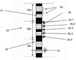
도 2는 2008 년 5 월 28 일 출원된 Villaret 등의 미국 특허 제8,492,704호의 도 3에서 가져온 선형 엔코더를 도시한다. 선형 엔코더(30)는 도시된 바와 같은 기계-감지 가능한 요소(31), 이 경우에 가동 부재(32) 상의 단일 선형 트랙 상에서 움직이는 광학 요소를 사용한다. 광학 센서인 센서(36.1 내지 36.5)는 고정 부재(34) 상에 선형 배열 상태로 고정된다.Figure 2 shows a linear encoder taken from Figure 3 of U.S. Patent No. 8,492,704 to Villaret et al. Filed on May 28, 2008. The
도 2에서, 가동 부재(32)상의 기계-감지 가능한 부재(31)는 또한 투광성 또는 비투광성 요소와 같은 광학 요소이며, 직선으로 배열된다. 이들은 38a, 38b 및 38c에 각각 나타나 있는 3개의 유사한 주기로 나누어지며, 각 주기는 20 개의 증분 위치 또는 섹터(41)를 포함하고 있다.In Fig. 2, the machine-
고정 부재(34)는 하나의 라인으로 배열되었으며, 또한 서로 동일하게 이격된 5개의 센서(36.1 내지 36.5)를 이동시킨다. 고정 부재(34)에 대한 가동 부재(32)의 초기 위치에서, 5개의 센서(36.1 내지 36.5)의 배열은 광학 요소의 한 주기의 길이, 즉 38a, 38b 또는 38c 로 표시된 바와 같이 한 주기의 패턴의 길이에 걸쳐 연장된다.The fixing
도 2에 도시된 패턴은 선형이고 주기적이다. 주기(38a 내지 38c)들 각각은 로터리 엔코더의 직선화된 형태로 간주될 수 있다.The pattern shown in Figure 2 is linear and periodic. Each of the
균등 분산 센서의 예에서는, 위치 모듈러 한 주기가 고려된다. 이 경우 n 개의 센서에 대해 "균등하게 분산된"이라는 용어는 센서(i)에 의한 감지된 위치(x(i))가 하기 관계를 확인한다는 것을 의미한다. 1부터 n까지 모든 i에 대하여, [(x(i+1)-x(i))modulo L]=±L/n, 여기서, L은 패턴의 한 주기의 길이다. 패턴은 판독될 때 그레이 코드를 생성하도록 배열될 수 있다. 그레이 코드는 2개의 연속적인 값이 단지 단일 숫자에 의해서만 변경되는 이진 코드이며, 오류 수정 요소를 제공하기 때문에 엔코더에서 유용하다.In the example of a uniform dispersion sensor, a position moduler period is considered. In this case, the term "evenly distributed" for n sensors means that the sensed position x (i) by the sensor i identifies the following relationship: For all i from 1 to n, [(x (i + 1) -x (i)) modulo L] = ± L / n, where L is the length of one period of the pattern. The pattern may be arranged to generate a gray code when read. Gray code is binary code in which two consecutive values are changed only by a single number and is useful in an encoder because it provides an error correction element.
도 2에서 설명된 배열은 감지 가능한 요소들의 단일 트랙에 기초한 그레이 코드 출력을 제공하는 반면에, 다른 시스템은 전형적으로 다수의 트랙 및 여러 개의 센서의 배열을 이용한다. 또한, 센서가 균일하게 분포되기 때문에, 표준 크기의 단순한 상업적으로 이용 가능한 센서가 제공될 수 있다.The arrangement described in FIG. 2 provides a gray code output based on a single track of detectable elements, while another system typically uses multiple tracks and multiple sensor arrays. In addition, since the sensors are uniformly distributed, a simple commercially available sensor of standard size can be provided.
도 2에서 설명된 배열에서, 측정된 위치는 하나의 패턴 주기에 관련된다. 따라서, 위치 정보는 1주기 길이의 모듈로(modulo)이며, 절대 위치는 초기 위치로부터의 증분에 의해 계산될 수 있다. 따라서, 이 배열은 절대치 엔코더를 제공하지 않는다.In the arrangement described in FIG. 2, the measured position is related to one pattern period. Thus, the position information is a modulo of one cycle length, and the absolute position can be calculated by the increment from the initial position. Thus, this arrangement does not provide an absolute encoder.
다른 측면에서, 이러한 배열은 이동 케이블 체인을 필요로 하지 않지만, 이동 요소는 이동 경로보다 길고, 따라서 큰 공간 및 많은 수의 감지 가능한 요소를 차지하여, 시스템의 고비용 및 대부분 비실용적인 큰 체적을 야기한다.In other respects, this arrangement does not require a moving cable chain, but the moving element is longer than the moving path, thus occupying a large space and a large number of detectable elements, resulting in a large and often impractical large volume of the system .
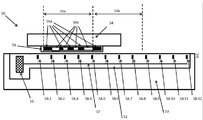
이제 본 발명의 제1의 바람직한 실시예에 따른 엔코더를 도시하고 있는 도 3을 참조한다. 도 3에서, 선형 장치(50)는 다시 고정 요소(53)와 이동 요소(54)를 갖고 있다. 이동 요소는 정지부(53) 상의 또는 그에 근접한 선형 경로 상에서 슬라이딩할 수 있다. 이동부(54)는 단일 트랙 상에 소정의 패턴으로 배열된 일련의 기계 감지 가능한 요소(56a 및 56b)를 갖고 있다. 감지 가능한 요소(56a)는 제1 특성, 예를 들어 N자기 극성을 가지며, 감지 가능한 요소(56b)는 제2 특성, 예를 들어 S 자기 극성을 갖고 있다. 등거리적으로 위치된 센서(58)(58.1 내지 58.12)는 PCB(52) 상에 배열되고 고정 부분에 고정되며 전체 선형 경로를 따라 연장되며, 따라서 두 부분의 모든 상대적인 움직임을 커버하는 센서가 있다.Reference is now made to Fig. 3 which shows an encoder according to a first preferred embodiment of the present invention. In Fig. 3, the
전술한 바와 같이, 본 실시예는 고정 요소 및 이동 요소와 관련하여 설명되며, 따라서 유리하게는 케이블이 없는 엔코더를 제공한다. 이동 와이어는 고가이고 기계적 진동의 원인이며 기계적인 고장을 겪을 수 있다. 그러나, 기계 감지 가능한 요소가 고정 요소 상에 있고 센서가 이동 요소 상에 있는 실시예 또한 가능하다.As described above, the present embodiment is described with respect to a fixed element and a moving element, thus advantageously providing an encoder without a cable. Moving wires are expensive and cause mechanical vibrations and can experience mechanical failure. However, embodiments in which the machine-sensible element is on the stationary element and the sensor is on the moving element are also possible.
센서(58)는 신호 및 전력을 위한 내장형 연결부를 갖는 인쇄 회로 기판 상에 단순히 장착된다.The sensor 58 is simply mounted on a printed circuit board having an internal connection for signal and power.
도 3에 나타나 있는 바와 같이, 센서들은 도 3의 선 57에 의해 개략적으로 나타나 있는, PCB 상의 도전 스트립에 의하여 전자 처리 유닛(55)에 연결된다.As shown in FIG. 3, the sensors are connected to the
균일하게 위치된 센서들 각각은 고유 어드레스를 가질 수 있으며, 이 어드레스는 PCB의 전도성 스트립 내에 고정 배선될 수 있다.Each of the uniformly positioned sensors may have a unique address, which may be fixedly wired into the conductive strip of the PCB.
균일하게 위치된 센서(58)들은 자기 센서일 수 있으며, 이 경우 기계-감지 가능한 요소(56)는 자석일 수 있다. 균일하게 위치된 자기 센서들은 편리하게는 홀 센서일 수 있다. 일반적으로 자기 선형 엔코더는 능동적으로 자화된 또는 수동적인 -가변 자기 저항-을 사용할 수 있으며, 스케일과 위치는 감지-코일 또는 홀 효과 또는 자기 저항성 판독 헤드를 사용하여 감지될 수 있다.The uniformly positioned sensors 58 may be magnetic sensors, in which case the machine-sensible element 56 may be a magnet. The uniformly positioned magnetic sensors may conveniently be Hall sensors. Generally, magnetic linear encoders can use actively magnetized or passive-variable magnetoresistance, and the scale and position can be sensed using a sense-coil or Hall effect or a magnetoresistive read head.
상대적으로 거친 것부터 상대적으로 미세한 것까지 범위의 다른 분해능 수준이 이용할 수 있다. 센서가 광학 센서가 아니면, 일반적으로 수백 마이크로미터에서 수 밀리미터 범위의 스케일 주기 또는 측정 간격은 마이크로미터 정도의 분해능을 허용할 수 있다.Different resolution levels range from relatively coarse to relatively fine. If the sensor is not an optical sensor, a scale period or measurement interval in the range of a few hundred micrometers to a few millimeters in general may allow resolution on the order of micrometers.
대안적으로, 센서는 도 2에서와 같은 광학 센서일 수 있으며, 예를 들어 셔터/모아레, 회절 또는 홀로그램 원리를 사용할 수 있다. 일반적인 증분 스케일 주기 또는 측정 간격은 수백 밀리미터에서부터 아래로 서브-마이크로미터 범위까지 달라질 수 있으며 뒤이은 보간은 나노미터만큼 미세한 분해능을 제공할 수 있다.Alternatively, the sensor may be an optical sensor as in FIG. 2 and may use, for example, shutter / moire, diffraction or hologram principles. A typical incremental scale period or measurement interval can vary from a few hundred millimeters down to a sub-micrometer range, and subsequent interpolation can provide as fine a resolution as nanometers.
본 실시예는 측정 간격의 크기에 의하여 분해능에 부과된 임의의 종속성을 제거할 수 있다.This embodiment can eliminate any dependency on the resolution by the size of the measurement interval.
다른 대안으로, 감지는 인덕티브 센서를 사용할 수 있다. 인덕티브 기술은 오염 물질에 대해 견고한 것으로 알려져 있다. 기계 감지 가능한 요소는 금속 내의 구멍에 의하여 또는 치차를 연장함으로써 형성될 수 있으며, 센서는 높은 주파수에서 동작되는 일련의 인덕터일 수 있다.Alternatively, sensing can use an inductive sensor. Inductive technology is known to be robust against pollutants. The machine-sensible element may be formed by a hole in the metal or by extending the gear, and the sensor may be a series of inductors operated at high frequencies.
정전 용량형 센서가 다른 대안이다. 정전 용량형 선형 엔코더는 판독기와 스케일 간의 정전 용량을 감지함으로써 작동한다. 대표적인 적용이 디지털 캘리퍼이다. 단점 중 하나는 불균일한 먼지에 대한 민감도이며 이는 국부적으로 상대 유전율을 변화시킬 수 있다.Capacitive sensors are another alternative. Capacitive linear encoders operate by sensing the capacitance between the reader and scale. Typical applications are digital calipers. One of the disadvantages is the sensitivity to non-uniform dust, which can change the relative permittivity locally.
다른 대안으로서, 센서는 예를 들어 미국특허 제3,820,110에 개시된 것과 같은 와전류 센서일 수 있다. As another alternative, the sensor may be an eddy current sensor, for example as disclosed in U.S. Patent No. 3,820,110.
다시 도 3을 참조하면, 엔코더 헤드(51)는 이동 요소(54)에 고정된다. 도 3의 특정 예에서, 2개의 감지 가능한 유닛(59a 및 59b)이 한정된다. 감지 가능한 유닛(59a)은 8개의 기계 감지 가능한 요소(56a 또는 56b)와 함께 완전히 장착된다. 감지 가능한 유닛(59b)은 단지 하나의 기계 감지 가능한 요소(56a)를 갖고 장착된다.Referring again to FIG. 3, the
캐리지 길이가 기계 가능한 유닛의 길이의 배수일 때마다 엔코더 헤드는 다수의 기계 감지 가능한 유닛을 포함할 수 있다. 그러면 활성 센서의 개수는 특정 패턴에 대해 한정된 최소 N 값보다 클 수 있으며, 위치의 여러 판독 값이 얻어질 수 있다. 다수의 판독 값은 유리하게는 위치 판독 값의 임의의 부정확성을 검출해야 하는 것을 요구하는 안전 규정 및 표준을 따르도록 사용될 수 있다.Each time the carriage length is a multiple of the length of the machineable unit, the encoder head may include a plurality of machine-sensible units. The number of active sensors can then be greater than the minimum N value defined for a particular pattern, and multiple readings of the position can be obtained. The plurality of readings may advantageously be used to comply with safety regulations and standards that require that any inaccuracy of the position readings be detected.
도 3을 참조하면, 어드레스(1 내지 12)는, 예를 들어 센서(58)에 할당된다. 감지 가능한 유닛 길이는 2개의 센서 사이의 거리의 N= 4배이다.Referring to FIG. 3, addresses 1 to 12 are assigned to, for example, a sensor 58. The detectable unit length is N = 4 times the distance between the two sensors.
제1 단계에서, 처리 유닛은 활성 센서를 검출한다. 바람직한 실시예에서, 기계 감지 가능한 요소는 N극 및 S극 자석이다. 이 경우, 센서는 홀 센서이며 N극 자석의 앞에 있을 때는 양의 값을, S극 자석 앞에 있을 때는 음의 값을, 그리고 임의의 자석 앞에 있지 않을 때, 비활성화일 때는 0 값에 가까운 값을 출력한다. In the first step, the processing unit detects the active sensor. In a preferred embodiment, the machine-sensible element is an N pole and an S pole magnet. In this case, the sensor is a hall sensor and outputs a positive value when it is in front of the N pole magnet, a negative value when it is before the S pole magnet, and a value close to 0 when it is not in front of any magnet, do.
처리 유닛은 N=4개의 활성 센서를 선택할 수 있다. 도 4에서, 예를 들어 어드레스(2, 3, 4 및 5)의 활성 센서(58.2, 58.3, 58.4 및 58.5)가 선택될 수 있다.The processing unit may select N = 4 active sensors. In Fig. 4, for example, active sensors 58.2, 58.3, 58.4 and 58.5 at addresses 2, 3, 4 and 5 may be selected.
각 선택된 센서에 대하여, 출력이 양의 값이면 불린 값(V) 1이 부여되며, 음수 값이면 0이 부여된다. 디지털 코드가 그후 계산된다.For each selected sensor, a positive value (V) 1 is given if the output is a positive value, and a negative value (V) is given if the output is negative. The digital code is then calculated.
![]()
![]()
엔코더의 패턴이 전처리된 테이블에 따라 활성 센서들 중 하나에 대해 중간 정밀도 위치를 제공할 수 있다는 점이 2008년 5월 28일 출원된 Villaret 등의 위에서 언급된 미국 특허 제8,492,704호로부터 알려져 있다. 각 센서의 정확한 위치는 처리 유닛에 사전 로딩될 수 있다. 따라서 중간 절대 위치가 계산될 수 있다.It is known from the aforementioned U.S. Patent No. 8,492,704, filed on May 28, 2008 by Villaret et al., That the pattern of the encoder can provide an intermediate precision position for one of the active sensors according to the preprocessed table. The exact position of each sensor can be pre-loaded into the processing unit. The intermediate absolute position can therefore be calculated.
고분해능 위치를 얻기 위하여, 센서 출력의 아날로그 값이 사용될 수 있다. 미국 특허 제 8,492,704 호에서와 같이, 상이한 특성을 갖는 기계 감지 가능한 요소의 앞에 있을 때 2개의 값 범위 사이의 중간 값에서 센서 출력의 적어도 2개의 아날로그 값이 있는 것을 보장하도록 센서 감도는 설계된다. 개시된 보간 알고리즘은 절대 고분해능 위치를 계산하는데 사용될 수 있다.In order to obtain a high resolution position, the analog value of the sensor output may be used. As in US 8,492,704, sensor sensitivity is designed to ensure that there are at least two analog values of the sensor output at an intermediate value between the two value ranges when in front of the machine-sensible element with different characteristics. The disclosed interpolation algorithm can be used to calculate absolute high resolution positions.
실시예에서, 감지 가능한 유닛은 균일하게 이격된 센서의 N=7과 동등한 길이에 걸쳐 연장된다. 이러한 구성은 7 비트 가능한 코드(127)의 효율적인 사용을 나타내는, 하나의 감지 가능한 요소 길이 내의 위치(98)의 중간 분해능을 제공한다. 임의의 다른 번호가 사용될 수 있으며, 센서와의 비트 사용의 유도를 위한 국제 특허 출원 공개 제WO2013/098803A호를 참조한다.In an embodiment, the detectable unit extends over a length equal to N = 7 of a uniformly spaced sensor. This configuration provides a median resolution of
미국 특허 제8,492,704호와 대조적으로, 활성 센서 세트는 위치에 따라 달라진다.In contrast to US Pat. No. 8,492,704, the active sensor set is position dependent.
다른 측면에서, 활성 센서의 개수가 N보다 크면, 즉 N+p이면, N개의 활성 센서 세트를 선택하기 위해 다수의 조합이 이용 가능하며, 따라서 절대 위치의 판독값의 동일한 개수가 계산될 수 있다. 동일 위치의 이러한 중복된 복수 판독 값은 엔코더가 안전 표준을 준수하도록 하는 데 사용될 수 있다.In another aspect, if the number of active sensors is greater than N, i. E., N + p, then multiple combinations are available to select the N active sensor sets, thus the same number of readings of the absolute position can be calculated . Such duplicate multiple readings of the same location can be used to ensure that the encoder complies with safety standards.
선형 트랙 상의 각 센서 위치의 고유한 부정확성으로 인하여 트랙의 초기 보정이 요구될 수 있다. 보정은 초기 설정 후에 또는 제조 중에 제공될 수 있으며 또는 개별 기계 가동시 및/또는 최종 사용자에 의한 요구대로 프로그래밍될 수 있다. The initial inaccuracy of the track may be required due to the inherent inaccuracy of each sensor position on the linear track. The correction may be provided after initial setup or during manufacturing, or may be programmed at the individual machine start-up and / or as requested by the end user.
센서의 유형에 따라, 활성 센서를 검출하기 위해 다양한 배열과 방법이 사용될 수 있다.Depending on the type of sensor, various arrangements and methods can be used to detect active sensors.
주어진 패턴을 위하여, 고정된 수(N)의 활성 센서가 코드를 계산하기 위하여 사용될 수 있다.For a given pattern, a fixed number (N) of active sensors can be used to compute the code.
활성 센서는 그의 이동 길이를 따라서 엔코더 헤드에 근접한 것으로 한정된다. 이동 거리는 2개의 맨 끝의 기계 감지 가능한 요소 사이의 경로 길이이다.The active sensor is limited to being close to the encoder head along its travel length. The travel distance is the path length between the two endmost machine-sensible elements.
한 배열에서, 엔코더 헤드는 센서 간격의 배수(P)인 길이에 걸쳐 연장되도록 설계되며, 여기서 P는 N보다 크거나 동일하다. 엔코더 헤드 말단이 센서와 정확하게 정렬되는 특별한 경우에서 활성 센서의 개수는 P에서 P+1까지 달라질 수 있다.In one arrangement, the encoder head is designed to extend over a length that is a multiple of the sensor spacing (P), where P is greater than or equal to N. The number of active sensors can vary from P to P + 1 in a special case where the encoder head end is aligned precisely with the sensor.
처리 유닛은 가치없는(null) 판독 값(V0)을 가지며 따라서 비활성인, 기계 감지 가능한 요소에 근접하지 않은 센서를 검출한다. 활성 센서는 주어진 측부에서 시작하는 모든 센서를 스캐닝함으로써 그리고 V0와는 다른 아날로그 값을 갖는 첫 번째 센서를 찾음으로써 발견된다. 범위는 첫 번째 센서에서 V0로부터 떨어진 값을 갖는 마지막 센서까지 연장된다. 특정 위치에서 좌측 또는 우측 활성 센서의 아날로그 값이 동일한 V0 값을 갖는 것이 발생할 수 있으며, 이는 센서가 비활성 상태이기 때문이 아니라 센서가 천위 범위에 내에 있기 때문이다. The processing unit detects a sensor that has a null reading (V 0 ) and is therefore not close to the inactive, machine-sensible element. An active sensor is found by scanning all sensors starting at a given side and looking for the first sensor with an analog value different from V 0 . The range extends from the first sensor to the last sensor with a value off V 0 . It can happen that the analogue values of the left or right active sensor at a particular location have the same V 0 value because the sensor is in the range of the heights rather than the inactive state.
그러나 검출된 활성 센서의 개수가 사전 한정된 값 P보다 낮을 수 있기 때문에 이러한 상황이 검출될 수 있다. P가 N과 같으면, 검출된 활성 신호의 개수는 N-1이며, 이 두 센서가 동일한 V0 값을 출력하고 기계 감지 가능한 유닛 길이만큼 거리를 두고 있고 따라서 양 센서가 활성인 경우 동일한 출력값을 갖기 때문에 처리 장치가 오른쪽 또는 왼쪽의 부가적인 홀 센서를 선택하는지 여부의 결과는 중요하지 않다. P가 N보다 큰 경우, 처리 유닛은 N개의 활성 센서를 선택할 수 있다.However, this situation can be detected because the number of detected active sensors may be lower than the predefined value P. If P is equal to N, then the number of detected active signals is N-1, the two sensors output the same V 0 value and are distant by the machine-sensible unit length, so that if both sensors are active, Therefore, the result of whether or not the processing apparatus selects the right or left additional hall sensor is not important. If P is greater than N, the processing unit may select N active sensors.
제2 배열에서, 엔코더 헤드의 이동 길이는 센서 간격의 배수 P와 센서 간격의 상당히 작은 부분을 합한 것이 되도록 설계된다. 또한, 엔코더 헤드의 이동 길이의 한쪽 끝단은 패턴의 가장 긴 기계 요소와 함께 센서 간격보다 긴 길이로 장착되도록 그리고 근접한 센서에 대해 V0와는 다른 값을 생성하도록 설계될 수 있다.In the second arrangement, the travel length of the encoder head is designed to be a multiple of the sensor spacing P plus a significantly smaller portion of the sensor spacing. Also, one end of the travel length of the encoder head may be designed to be mounted with the longest mechanical element of the pattern longer than the sensor spacing and to produce a different value from V 0 for the proximate sensor.
이러한 경우, 활성 센서의 개수는 N보다 크거나 같은 상수 P이다. P=N이면, 양 말단에서의 활성 센서는 동일한 값을 가질 수 있으며 상황은 제1 배열을 위한 위와 동일한 고려 사항에 의하여 해결될 수 있다.In this case, the number of active sensors is a constant P equal to or greater than N. [ If P = N, the active sensors at both ends can have the same value and the situation can be solved by the same considerations for the first arrangement.
P> N 이면, 처리 유닛은 항상 N개의 활성 센서를 선택할 수 있으며 제1 활성 센서로부터 N개의 센서를 카운팅할 수 있다.If P > N, the processing unit can always select N active sensors and count N sensors from the first active sensor.
제3 배열에서, 주어진 특성 A의 부가적인 기계 감지 가능한 요소는 센서 간격의 배수 X인 길이를 갖는 엔코더 헤드 연장부 외부에 위치될 수 있으며, 여기서 X는 주어진 패턴에 대한 특성 A의 기계 센서 요소에 근접한 활성 센서의 가능한 최대 개수보다 크다. 부가적인 기계 요소에 근접한 X개 또는 그 이상의 활성 센서를 검출함으로써, 활성 센서 범위 한계를 찾을 수 있다.In a third arrangement, an additional machine-sensible element of a given characteristic A may be located outside the encoder head extension with a length that is a multiple of the sensor spacing X, where X is a mechanical sensor element of characteristic A for a given pattern Is greater than the maximum possible number of nearby active sensors. By detecting X or more active sensors proximate additional mechanical elements, an active sensor range limit can be found.
활성 센서를 위치시키고 선택하기 위하여 당업자는 다양한 다른 배열 및 방법을 상상할 수 있다.Those skilled in the art will envision various other arrangements and methods for locating and selecting active sensors.
센서가 고정 요소 상에 있음에 따라, 사실상 센서는 인쇄 회로 기판 상에 직접적으로 장착될 수 있으며, 전원 및 신호용 정적 연결부를 구비할 수 있다.As the sensor is on the stationary element, in effect the sensor can be mounted directly on the printed circuit board and can have a static connection for power and signal.
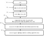
이제 위치 기반의 낮은 중간 및 고분해능 위치를 계산하는 과정을 도시하는 간략화된 흐름도인 도 4를 참조한다.Reference is now made to Fig. 4, which is a simplified flow diagram illustrating the process of calculating location-based low intermediate and high resolution locations.
바람직한 실시예에서, 처리 유닛은 엔코더의 다양한 계산을 할 수 있는 마이크로컨트롤러 또는 FPGA일 수 있다.In a preferred embodiment, the processing unit may be a microcontroller or FPGA capable of various calculations of the encoder.
시작 81은 처리 유닛의 위치 계산 과정을 시작하는 이벤트를 나타낸다. 이 이벤트는, 예를 들어 통신 회선을 통하여 수신된 호스트 컴퓨터 또는 드라이브로부터의 요청일 수 있다.The
모듈 82에서, 처리 유닛은 전술한 방법 중 하나를 사용하여 활성 센서에 대한 탐색을 실행한다.In
모듈 83에서, 처리 유닛은 N 개의 활성 센서를 선택하며, 따라서 그들의 어드레스 모듈로(modulo)(N)은 0에서 N-1의 범위를 커버한다.In
모듈 84에서, 처리 유닛은 다음의 식을 이용하여 코드를 계산한다:
In
![]()
![]()
V는 활성 센서 출력의 불린 값으로, 활성 센서가 제1 특성의 기계 감지 가능한 요소에 근접한 상태이며, V = 1이고 그렇지 않으면 V = 0이다. 처리 유닛은 그후 모듈로(어드레스, N) = n0을 만족하는 어드레스를 갖는 센서(S0)에 대한 중간 분해능 위치를 판독하며, 여기서 n0은 N보다 작은, 미리 설정된 정수, 즉 0≤n0 <N이다. 이 상대 위치는 엔코더의 선택된 패턴에 대해 구축된 사전 한정된 테이블에 의해 주어진다.V is the boolean value of the active sensor output, with the active sensor in close proximity to the machine-sensible element of the first characteristic, V = 1, otherwise V = 0. The processing unit is then in the module (the address, N) = n reads out the intermediate resolution of location for the sensor (S0) having an address that satisfies 0, where n 0 is smaller than N, the preset constant, i.e. 0≤n0 < N. This relative position is given by a predefined table established for the selected pattern of encoders.
모듈 85에서, 절대 중간 분해능 위치는 중간 분해능 상대 위치에 센서(S0)의 저분해능 위치 데이터를 가산함으로써 계산된다. 이러한 저분해능 위치는 특정 엔코더 설계의 데이터를 이용하여 또는 보정 과정 동안에 높은 정밀도로 사전 기록될 수 있다.In
모듈 86에서, 활성 센서의 전이 아날로그 출력의 아날로그 값은 미국 특허 제8,492,704호에 설명된 알고리즘과 유사한 알고리즘에 의하여 처리된다.In
이제 와전류 검출에 기초한 선형 엔코더를 도시하는 간략화된 도면인 도 5를 참고한다. 이동부는 패턴(96)을 형성하도록 번갈아가며 배열된 금속(92) 요소와 비금속(94) 요소의 스트립이 형성된 PCB(90)를 갖는다. 고정부 상에는 코일(100)이 장착된 PCB(98)가 있다. 코일이 금속의 측정 근접 상태가 됨에 따라, 와전류가 코일 내에 생성되고 검출될 수 있다.Reference is now made to Fig. 5, which is a simplified diagram illustrating a linear encoder based on eddy current detection. The moving part has a
이제 유도성 검출에 기초한 선형 엔코더를 도시한 간략화된 도면인 도 6을 참조한다. 이동부는 패턴을 형성하도록 배치된, 금속이 존재하지 않은 구멍(114)을 갖는 금속 스트립(112)이 형성된 PCB(110)를 갖고 있다. 고정부 상에는 코일(120)이 장착된 PCB(118)가 있다. 코일이 구멍의 측정 근접 상태가 됨에 따라, 인덕턴스가 코일 내의 공진을 줄이고 검출될 수 있다.Reference is now made to Fig. 6, which is a simplified diagram illustrating a linear encoder based on inductive detection. The moving part has a
위에서 설명된 바와 같이, 센서는 PCB에 장착될 수 있다. 그러나, PCB는 열에 민감할 수 있으며, 선형 모터가 뜨거워지면 하부 PCB의 팽창으로 인하여 센서는 위치를 바꿀 수 있다. 센서의 위치가 변경되기 시작하면 정확한 측정이 손상된다. 문제를 해결할 수 있는 다수의 방법이 있다. 예를 들어, 센서는 열에 민감하지 않은 물질의 하부 고정층에 고정될 수 있다. 대안적으로, PCB 팽창이 전체적으로 선형 모터 전체의 팽창과 일치하도록 PCB는 선택된 단일 위치에 장착될 수 있다. 이 대안의 변형은 PCB에 절개부를 제공하며, 이 절개부에서 센서는 온도 안정적인 물질의 하부 플레이트에 장착되고 고정된다. 다수의 다른 해결책 자체가 당 업자에게 제안될 것이다.As described above, the sensor can be mounted on the PCB. However, the PCB can be sensitive to heat, and if the linear motor becomes hot, the sensor can be repositioned due to the inflation of the bottom PCB. When the position of the sensor begins to change, accurate measurements are impaired. There are a number of ways to solve the problem. For example, the sensor may be secured to a lower fixation layer of a material that is not heat sensitive. Alternatively, the PCB may be mounted at a selected single location such that the PCB expansion is generally consistent with the expansion of the linear motor as a whole. This alternative variant provides an incision in the PCB where the sensor is mounted and secured to a lower plate of temperature-stable material. Many other solutions themselves will be proposed to the practitioner.
실시예는 견고성, 내구성 및 비용과 관련된 개선을 수행하면서 광학 절대치 엔코더와 동일하거나 더 높은 수준의 분해능을 제공할 수 있는 자기 절대치 선형 엔코더를 제공 할 수 있다.Embodiments can provide a magnetic absolute linear encoder that can provide the same or a higher level of resolution than an optical absolute encoder while performing improvements related to robustness, durability, and cost.
본 출원으로부터 완성된 특허의 권리 기간 동안에 많은 관련 센서 및 선형 드라이브 그리고 선형 모터가 개발될 것이며 대응하는 조건의 범위는 이러한 모든 새로운 기술을 선험적으로 포함하도록 의도된다.During the term of the patent from this application, many related sensors and linear drives and linear motors will be developed and the range of corresponding conditions is intended to include all these new technologies a priori.
용어 "포함하다", "포함한다", "포함하는", "구성한다", "구성하는" 및 "갖고 있는" 및 그들의 활용형은 "포함하지만 이에 제한되지 않은"을 의미한다.The terms "comprise," " comprise, "" comprise," " comprise, "" comprise ", and &
용어 "구성된"은 "포함하고 제한된"을 의미한다.The term "comprising" means "including and limiting ".
본 명세서에서 사용된 바와 같이, 단수 형태("a", "an" 및 "the")는 문맥이 명확하게 달리 지시하지 않는 한 다수의 대상(reference)를 포함한다.As used herein, the singular forms "a", "an" and "the" include a number of references unless the context clearly dictates otherwise.
명확한 설명을 위해 별도의 실시예들의 문맥에서 설명된 본 발명의 특정 특징들은 또한 단일 실시예에서 조합하여 제공될 수 있으며, 위의 설명은 이 조합이 명백하게 작성된 것으로 해석되어야 한다. 반대로, 간략화를 위해, 단일 실시예의 문맥에서 설명된 본 발명의 다양한 특징들은 또한 개별적으로 또는 임의의 적절한 부조합으로 또는 본 발명의 임의의 다른 설명된 실시예에 적절한 것으로 제공될 수 있으며, 위의 설명은 이 개별 실시예가 명백하게 기재된 것으로 해석되어야 한다. 다양한 실시예의 문맥에서 설명된 특정 특징들은 실시예가 이들 요소 없이는 작동하지 않는 한, 이 실시예의 본질적인 특징으로 간주되어서는 안된다.For purposes of clarity, certain features of the invention set forth in the context of separate embodiments may also be provided in combination in a single embodiment, and the above description should be construed as an obvious combination of the foregoing. Conversely, for purposes of simplicity, various features of the invention, which are, in the context of a single embodiment, may also be provided individually or in any suitable subcombination, or as appropriate to any other described embodiment of the present invention, The description should be construed as an explicit description of these individual embodiments. Certain features described in the context of various embodiments should not be considered essential features of this embodiment unless the embodiment operates without these elements.
본 발명이 그의 특정 실시예와 관련하여 설명되었지만, 많은 대안, 변형 및 변화가 당 업자에게 명백할 것이라는 점이 분명하다. 따라서, 첨부된 청구범위의 사상 및 넓은 범위 내에 있는 이러한 모든 대안, 변형 및 변화를 포함하는 것으로 의도된다.While the invention has been described in connection with specific embodiments thereof, it is evident that many alternatives, modifications and variations will be apparent to those skilled in the art. Accordingly, it is intended to embrace all such alternatives, modifications and variations that fall within the spirit and broad scope of the appended claims.
본 명세서에서 언급된 모든 간행물, 특허 및 특허 출원은 각 개별 간행물, 특허 또는 특허 출원이 본 명세서 내에 참고로 포함되는 것으로 구체적으로 그리고 개별적으로 표시된 것과 동일한 정도로 본 명세서에 전체적으로 참고로 포함된다. 또한, 본 출원에서 임의의 참조 문헌의 인용 또는 식별은 그러한 참조가 본 발명의 선행 기술로서 이용 가능하다는 인정으로 해석되어서는 안된다. 부분 표제가 사용되는 한, 이들은 반드시 제한적인 것으로 해석되어서는 안된다.All publications, patents, and patent applications mentioned in this specification are herein incorporated in their entirety by reference to the same extent as if each individual publication, patent or patent application was specifically and individually indicated to be incorporated by reference. Further, citation or identification of any reference in this application should not be construed as an admission that such reference is available as prior art to the present invention. As long as the partial headings are used, they are not necessarily to be construed as limiting.
Claims (25)
길이를 따라서 변화하는 특성을 포함하는 설정된 패턴으로 상기 부분의 제1 부분 상에 배열된 다수의 기계 감지 가능한 요소; 및
상기 제1 이동 말단 위치와 상기 제2 이동 말단 위치 사이의 상기 선형 이동 범위 전체를 따라서 상기 부분의 제2 부분을 따라 배열되며, 그로 인하여 상기 변위를 측정하고 암호화하는, 균일하게 위치된 다수의 센서를 포함하는 선형 엔코더.A linear position measuring device for a linear position measuring device having a fixed portion and a moving portion, said linear position measuring device having a linear portion designed to measure and encode a relative displacement between said fixed portion and said moving portion along a linear range of movement between a first moving end position and a second moving end position In the encoder,
A plurality of machine-sensible elements arranged on a first portion of the portion in a set pattern that includes characteristics that vary along a length; And
A plurality of uniformly positioned sensors arranged along a second portion of the portion along the entire linear range of motion between the first and second moving end positions to measure and encode the displacement, / RTI >
상기 전체 변위 길이에 걸쳐 이격된 다수의 센서를 제공하고;
상기 패턴을 따르는 거리에 걸쳐 변화하는 특성을 포함하고 있는, 기계 감지 가능한 요소의 설정된 패턴을 제공하며;
상기 변위 길이에 걸친 상기 다수의 센서에 대하여 상기 패턴을 선형적으로 변위시키고; 그리고
상기 다수의 센서를 이용하여 상기 변위를 측정하는 것을 포함하는 방법.In an absolute linear encryption method of relative displacement between two parts over an entire linear displacement length,
Providing a plurality of sensors spaced over the entire displacement length;
Providing an established pattern of machine-sensible elements that includes characteristics that vary over a distance along the pattern;
Linearly displacing the pattern with respect to the plurality of sensors over the displacement length; And
And measuring the displacement using the plurality of sensors.
현재 기계 감지 가능한 요소에 인접한 센서를 활성 센서로 검출하고;
상기 활성 센서의 위치를 기초로 제1 절대 저분해능 위치를 계산하며;
N 비트의 각각을 상기 활성 센서의 불린(Boolean) 출력 값으로 설정함으로써 다수의 N 비트의 코드를 계산하여, 그로 인하여 상기 코드가 상기 활성 센서 중 하나에 대하여 중간 분해능 위치를 한정하며;
상기 제1 절대 저분해능 위치 값을 상기 제2 상대적 중간 분해능 위치 값과 조합하여 절대 중간 분해능 위치를 계산하는 것을 포함하는 방법. 14. The method of claim 13,
Detecting a sensor adjacent to the current machine-sensible element as an active sensor;
Calculate a first absolute low resolution position based on the position of the active sensor;
Computing a plurality of N bits of code by setting each of the N bits to a Boolean output value of the active sensor such that the code defines an intermediate resolution position for one of the active sensors;
And combining the first absolute low resolution position value with the second relative medial resolution position value to calculate an absolute medial resolution position.
상기 제1 특성 그리고 그렇지 않으면 제2 값을 갖는 기계 감지 가능한 요소의 사전 한정된 근접 범위 내에 있음을 나타내는 범위 내에 각 센서 아날로그 출력 값이 있을 때 각 아날로그 출력을 제1 불린 값으로 설정하고; 그리고
상기 센서의 아날로그 출력으로부터 고분해능 위치를 계산하는 것을 포함하는 방법.22. The method of claim 21, wherein when the sensor outputs an analog value,
Set each analog output to a first boolean value when there is an angle sensor output value within a range that is within a predefined proximity of the machine-sensible element having the first characteristic and the second value; And
And calculating a high resolution position from the analog output of the sensor.
설정된 패턴으로 상기 부분들 중 제1 부분 상에 배열된 다수의 기계 감지 가능한 요소; 및
상기 부분들 중 제2 부분 상에 배열되고 임의의 주어진 시간에 다수의 센서의 부세트만이 기계 감지 가능한 요소에 근접하도록 배열된, 다수의 균일하게 위치된 센서를 포함하는 선형 엔코더.A linear position measurement feedback device having a fixed portion and a movable portion, said linear position measurement feedback device having a fixed portion and a movable portion, said linear position measurement feedback device having a fixed portion and a movable portion and configured to measure and encode relative displacement between said fixed portion and said movable portion along a linear range of movement between a first and a second, In a linear encoder,
A plurality of machine-sensible elements arranged on a first portion of the portions in a set pattern; And
A plurality of uniformly positioned sensors arranged on a second portion of the portions and arranged such that only a subset of the plurality of sensors is proximate to the machine-sensible element at any given time.
25. The linear encoder of claim 24, wherein the second portion is a fixed portion.
Applications Claiming Priority (3)
| Application Number | Priority Date | Filing Date | Title |
|---|---|---|---|
| US201662307516P | 2016-03-13 | 2016-03-13 | |
| US62/307,516 | 2016-03-13 | ||
| PCT/IL2017/050318 WO2017158595A1 (en) | 2016-03-13 | 2017-03-13 | Position encoder |
Publications (1)
| Publication Number | Publication Date |
|---|---|
| KR20180122377A true KR20180122377A (en) | 2018-11-12 |
Family
ID=59850641
Family Applications (1)
| Application Number | Title | Priority Date | Filing Date |
|---|---|---|---|
| KR1020187028324A KR20180122377A (en) | 2016-03-13 | 2017-03-13 | Position encoder |
Country Status (13)
| Country | Link |
|---|---|
| US (1) | US10845219B2 (en) |
| EP (1) | EP3430713B1 (en) |
| JP (1) | JP7023872B2 (en) |
| KR (1) | KR20180122377A (en) |
| CN (1) | CN109075690B (en) |
| DK (1) | DK3430713T3 (en) |
| ES (1) | ES2910796T3 (en) |
| HU (1) | HUE058232T2 (en) |
| IL (1) | IL261764B2 (en) |
| PL (1) | PL3430713T3 (en) |
| PT (1) | PT3430713T (en) |
| SI (1) | SI3430713T1 (en) |
| WO (1) | WO2017158595A1 (en) |
Cited By (2)
| Publication number | Priority date | Publication date | Assignee | Title |
|---|---|---|---|---|
| CN110954129A (en) * | 2019-12-19 | 2020-04-03 | 北京猎户星空科技有限公司 | Method, device, equipment and medium for determining mileage count data |
| KR20210094352A (en) * | 2020-01-21 | 2021-07-29 | (주)가온솔루션 | Encorder moving apparatus and control method using the same |
Families Citing this family (11)
| Publication number | Priority date | Publication date | Assignee | Title |
|---|---|---|---|---|
| EP3430713B1 (en) | 2016-03-13 | 2022-01-26 | Servosense (SMC) Ltd. | Position encoder |
| US10513276B2 (en) * | 2016-11-06 | 2019-12-24 | Guoqiang YANG | Positioning guidance system and method based on guide rails |
| JP6787260B2 (en) * | 2017-06-14 | 2020-11-18 | 株式会社デンソー | Position sensor |
| DE102019118693A1 (en) * | 2019-07-10 | 2021-01-14 | Ewellix AB | Position sensors, position determination methods and linear actuators |
| CN110375066A (en) * | 2019-07-16 | 2019-10-25 | 温州长江汽车电子有限公司 | A kind of shift inductor and its application method |
| CN110375063B (en) * | 2019-07-16 | 2020-11-17 | 温州长江汽车电子有限公司 | Gear shifting method of gear shifter |
| CN112583968B (en) * | 2020-12-08 | 2023-05-05 | Oppo广东移动通信有限公司 | Electronic equipment |
| CN112729089B (en) * | 2020-12-28 | 2022-08-19 | 无锡广联数字传感科技有限公司 | Displacement sensor applied to multiple occasions |
| CN112902817B (en) * | 2021-02-08 | 2022-11-08 | 经登企业股份有限公司 | Magnetic linear position sensor |
| CN112902818B (en) * | 2021-02-08 | 2022-11-08 | 经登企业股份有限公司 | Method for calibrating magnetic linear position sensor |
| TWI790843B (en) * | 2021-12-06 | 2023-01-21 | 群光電子股份有限公司 | Input device and control method thereof |
Family Cites Families (20)
| Publication number | Priority date | Publication date | Assignee | Title |
|---|---|---|---|---|
| US3820110A (en) | 1973-03-22 | 1974-06-25 | C Henrich | Eddy current type digital encoder and position reference |
| US5994798A (en) | 1998-02-26 | 1999-11-30 | Anorad Corporation | Closed-path linear motor |
| US5907200A (en) | 1998-02-26 | 1999-05-25 | Anorad Corporation | Linear encoder |
| JP3347766B2 (en) * | 1992-06-08 | 2002-11-20 | 日本トムソン株式会社 | Linear encoder and guide unit having the same |
| JP2861712B2 (en) * | 1993-02-09 | 1999-02-24 | トヨタ車体株式会社 | Linear encoder |
| DE19518664C2 (en) | 1995-05-20 | 2003-02-13 | Christian Rathjen | Method for determining the position of two bodies that can be moved relative to one another |
| US7262523B1 (en) * | 1998-02-26 | 2007-08-28 | Anorad Corporation | Wireless encoder |
| US5925943A (en) | 1998-02-26 | 1999-07-20 | Anorad Corporation | Modular wireless linear motor |
| US6492911B1 (en) | 1999-04-19 | 2002-12-10 | Netzer Motion Sensors Ltd. | Capacitive displacement encoder |
| JP4094799B2 (en) * | 2000-06-22 | 2008-06-04 | 日本トムソン株式会社 | Slide device with built-in movable magnet type linear motor |
| JP4504553B2 (en) | 2000-12-01 | 2010-07-14 | 株式会社ミツトヨ | Encoder for detecting relative position |
| WO2002046704A1 (en) * | 2000-12-08 | 2002-06-13 | Micro-Epsilon Messtechnik Gmbh & Co. Kg | Device and method for detecting the position of a target |
| JP2003070225A (en) | 2001-06-19 | 2003-03-07 | Rockwell Internatl Corp | Path module for linear motor, modular linear motor system, and controlling method therefor |
| US7135673B2 (en) | 2004-10-29 | 2006-11-14 | The Boeing Company | Imaging rotation angle absolute encoder |
| IL183471A0 (en) | 2007-05-28 | 2007-09-20 | Yaskawa Europ Technology Ltd | Absolute encoder |
| DE102007038845A1 (en) | 2007-08-16 | 2009-03-19 | Dorma Gmbh + Co. Kg | Arrangement of stator modules in a linear motor |
| DE102011085636A1 (en) | 2011-11-02 | 2013-05-02 | Hamilton Bonaduz Ag | Linear motor with multiple sensor units and modular stator construction |
| KR101953821B1 (en) | 2011-12-28 | 2019-03-04 | 세르보센스 (에스엠씨) 엘티디. | High resolution encoder device |
| CA2949562C (en) | 2014-06-02 | 2023-05-16 | Ats Automation Tooling Systems Inc. | Linear motor system with powered curvilinear track sections |
| EP3430713B1 (en) | 2016-03-13 | 2022-01-26 | Servosense (SMC) Ltd. | Position encoder |
-
2017
- 2017-03-13 EP EP17765982.8A patent/EP3430713B1/en active Active
- 2017-03-13 PT PT177659828T patent/PT3430713T/en unknown
- 2017-03-13 ES ES17765982T patent/ES2910796T3/en active Active
- 2017-03-13 CN CN201780025197.6A patent/CN109075690B/en active Active
- 2017-03-13 SI SI201731126T patent/SI3430713T1/en unknown
- 2017-03-13 KR KR1020187028324A patent/KR20180122377A/en not_active Application Discontinuation
- 2017-03-13 JP JP2018566661A patent/JP7023872B2/en active Active
- 2017-03-13 PL PL17765982T patent/PL3430713T3/en unknown
- 2017-03-13 HU HUE17765982A patent/HUE058232T2/en unknown
- 2017-03-13 DK DK17765982.8T patent/DK3430713T3/en active
- 2017-03-13 WO PCT/IL2017/050318 patent/WO2017158595A1/en active Application Filing
- 2017-03-13 US US16/084,240 patent/US10845219B2/en active Active
-
2018
- 2018-09-13 IL IL261764A patent/IL261764B2/en unknown
Cited By (2)
| Publication number | Priority date | Publication date | Assignee | Title |
|---|---|---|---|---|
| CN110954129A (en) * | 2019-12-19 | 2020-04-03 | 北京猎户星空科技有限公司 | Method, device, equipment and medium for determining mileage count data |
| KR20210094352A (en) * | 2020-01-21 | 2021-07-29 | (주)가온솔루션 | Encorder moving apparatus and control method using the same |
Also Published As
| Publication number | Publication date |
|---|---|
| WO2017158595A1 (en) | 2017-09-21 |
| IL261764A (en) | 2018-10-31 |
| DK3430713T3 (en) | 2022-04-25 |
| US10845219B2 (en) | 2020-11-24 |
| US20190056247A1 (en) | 2019-02-21 |
| SI3430713T1 (en) | 2022-05-31 |
| EP3430713B1 (en) | 2022-01-26 |
| PT3430713T (en) | 2022-04-12 |
| IL261764B2 (en) | 2023-06-01 |
| JP2019512709A (en) | 2019-05-16 |
| CN109075690B (en) | 2021-05-11 |
| HUE058232T2 (en) | 2022-07-28 |
| CN109075690A (en) | 2018-12-21 |
| JP7023872B2 (en) | 2022-02-22 |
| WO2017158595A9 (en) | 2018-06-14 |
| EP3430713A1 (en) | 2019-01-23 |
| ES2910796T3 (en) | 2022-05-13 |
| EP3430713A4 (en) | 2019-10-23 |
| PL3430713T3 (en) | 2022-05-30 |
Similar Documents
| Publication | Publication Date | Title |
|---|---|---|
| KR20180122377A (en) | Position encoder | |
| KR101953821B1 (en) | High resolution encoder device | |
| CN111542730B (en) | Linear displacement measuring device for determining an absolute position and linear guide | |
| JP6143885B2 (en) | Method for self-calibrating a rotary encoder | |
| KR101723664B1 (en) | Apparatus adapted to provide an indication of an angular position of an input member over multiple turns | |
| EP1782023A2 (en) | Scale reading apparatus | |
| JP2008129018A (en) | Device for measuring position | |
| EP3091339B1 (en) | Nonvolatile rotation sensor with spiral track | |
| ES2757748T3 (en) | Angular measuring device and method for operating an angular measuring device | |
| US20080164830A1 (en) | Synchronous Linear Motor with Non-Contacting Scanning of the Toothed Structure of the Secondary Part | |
| JP2023503812A (en) | Position measurement of the mobile unit relative to the fixed unit | |
| KR20080085784A (en) | Position detector with tilt sensor | |
| CN106464233A (en) | Impedance tuners with position feedback | |
| JP2010539506A (en) | Sequential reading type absolute position sensor | |
| EP3098571B1 (en) | Nonvolatile rotation sensor with magnetic particle in serpentine track | |
| JP2010508506A (en) | Positioning device | |
| JP2007127560A (en) | Position-detecting device, scale, and method of resetting origin of the position-detecting device | |
| KR20230150302A (en) | High-resolution absolute vector encoder | |
| JP2023543606A (en) | Absolute position encoders for measuring instruments | |
| JP2006145523A (en) | Device and method for measuring spatial position of first object to second object |
Legal Events
| Date | Code | Title | Description |
|---|---|---|---|
| E902 | Notification of reason for refusal | ||
| E601 | Decision to refuse application | ||
| E601 | Decision to refuse application | ||
| E801 | Decision on dismissal of amendment |