KR20170120156A - Press molding method, method for manufacturing component in which said press molding method is used, and component manufactured using said press molding method - Google Patents
Press molding method, method for manufacturing component in which said press molding method is used, and component manufactured using said press molding method Download PDFInfo
- Publication number
- KR20170120156A KR20170120156A KR1020177026798A KR20177026798A KR20170120156A KR 20170120156 A KR20170120156 A KR 20170120156A KR 1020177026798 A KR1020177026798 A KR 1020177026798A KR 20177026798 A KR20177026798 A KR 20177026798A KR 20170120156 A KR20170120156 A KR 20170120156A
- Authority
- KR
- South Korea
- Prior art keywords
- flange
- curved
- deformation
- fillet
- vertical wall
- Prior art date
Links
Images


Classifications
-
- B—PERFORMING OPERATIONS; TRANSPORTING
- B21—MECHANICAL METAL-WORKING WITHOUT ESSENTIALLY REMOVING MATERIAL; PUNCHING METAL
- B21D—WORKING OR PROCESSING OF SHEET METAL OR METAL TUBES, RODS OR PROFILES WITHOUT ESSENTIALLY REMOVING MATERIAL; PUNCHING METAL
- B21D22/00—Shaping without cutting, by stamping, spinning, or deep-drawing
- B21D22/20—Deep-drawing
- B21D22/26—Deep-drawing for making peculiarly, e.g. irregularly, shaped articles
-
- B—PERFORMING OPERATIONS; TRANSPORTING
- B21—MECHANICAL METAL-WORKING WITHOUT ESSENTIALLY REMOVING MATERIAL; PUNCHING METAL
- B21D—WORKING OR PROCESSING OF SHEET METAL OR METAL TUBES, RODS OR PROFILES WITHOUT ESSENTIALLY REMOVING MATERIAL; PUNCHING METAL
- B21D22/00—Shaping without cutting, by stamping, spinning, or deep-drawing
- B21D22/20—Deep-drawing
- B21D22/206—Deep-drawing articles from a strip in several steps, the articles being coherent with the strip during the operation
-
- B—PERFORMING OPERATIONS; TRANSPORTING
- B21—MECHANICAL METAL-WORKING WITHOUT ESSENTIALLY REMOVING MATERIAL; PUNCHING METAL
- B21D—WORKING OR PROCESSING OF SHEET METAL OR METAL TUBES, RODS OR PROFILES WITHOUT ESSENTIALLY REMOVING MATERIAL; PUNCHING METAL
- B21D24/00—Special deep-drawing arrangements in, or in connection with, presses
- B21D24/005—Multi-stage presses
Abstract
(과제) 고강도의 금속판으로부터 폭 방향으로 만곡된 부품을 프레스 성형할 때의 수축 플랜지 변형에 의한 주름의 발생 및 연신 플랜지 변형에 의한 균열의 발생을 억제하는 것에 있다.
(해결 수단) 평판상의 블랭크로부터, 모자형 또는 コ 자형의 단면 형상을 가짐과 함께, 길이 방향을 따라 폭 방향으로 만곡된 만곡부와 그 만곡부의 양단에 연결되는 직변부를 갖는 부품을 프레스 성형할 때에, 천판부와, 그 천판부의 양측 단부에 필릿부를 개재하여 상단부가 연결되는 세로벽부와, 그것들 세로벽부의 하단부에 필릿부를 개재하여 내측 단부가 연결되는 플랜지부를 구비하는 모자형의 단면 형상을 거쳐 모자형 또는 コ 자형의 단면 형상으로 드로 성형하고, 그 드로 성형시에, 상기 만곡부의 상기 플랜지부에 발생하는 둘레 방향의 인장 변형 혹은 둘레 방향의 압축 변형을 완화시키는 상기 만곡부의 상기 플랜지부의 재료 이동을 일으키게 하는 것을 특징으로 하는 프레스 성형 방법이다.(PROBLEM TO BE SOLVED BY THE INVENTION) It is an object of the present invention to suppress the generation of wrinkles due to the shrinkage flange deformation when the component bent in the width direction from the high-strength metal plate is press-molded and the occurrence of cracks due to the deformation of the stretch flange.
When a component having a hat or a U-shaped cross section from a flat blank and having a curved portion curved in the width direction along the longitudinal direction and a side portion connected to both ends of the curved portion is press molded, And a flange portion having an inner end connected to the lower end portion of the vertical wall portion through a fillet portion, through a hat-shaped cross-sectional shape, the cap having a top plate portion, Shaped or cross-sectional shape of the flange portion of the curved portion to reduce the tensile deformation in the circumferential direction or the compressive deformation in the circumferential direction generated in the flange portion of the curved portion during the drawing, In the press forming step.
Description
본 발명은, 모자형 또는 コ 자형의 단면 형상을 갖고, 길이 방향을 따라 폭 방향으로 만곡된 부품의 프레스 성형 방법에 관한 것으로, 특히 연신 플랜지 변형에 의한 균열과, 수축 플랜지 변형에 의한 주름의 발생을 억제하는 프레스 성형 방법에 관한 것이다. 또한 본 발명은, 그 프레스 성형 방법을 사용하여 제조된, コ 자형 또는 모자형의 단면 형상을 갖고, 길이 방향을 따라 폭 방향으로 만곡된 프레스 제품으로서의 부품에 관한 것이기도 하다.The present invention relates to a press forming method for a component having a hat or a U-shaped cross section and curved in the width direction along the longitudinal direction, and particularly relates to a method of press forming a component by a stretch flange deformation and a wrinkle To a press molding method. The present invention also relates to a component as a pressed product having a U-shaped or hat-shaped cross-sectional shape manufactured by the press forming method and curved in the width direction along the longitudinal direction.
최근, 자동차의 충돌 안전성과 차체의 경량화를 양립하기 위해, 보다 고강도의 금속판이 요구되고 있다. 그러나, 금속판은 인장 강도가 향상될수록 프레스 성형성에 크게 관련된 연성이 저하되는 경향이 있다. 그 때문에, 소재의 연성이 성형성에 크게 영향을 미치는 장출 (張出) 성형보다, 폼 (굽힘) 성형이나 드로 (드로잉) 성형이 다용되는 경향이 있다.In recent years, a metal plate with a higher strength is required in order to make both the crash safety of an automobile and the weight reduction of a vehicle body compatible. However, as the tensile strength of the metal plate is improved, the ductility largely related to the press formability tends to decrease. Therefore, there is a tendency that foam (bending) molding or drawing (drawing) molding is more used than the extrusion molding in which the ductility of the material greatly affects the moldability.
드로 성형에서는, 먼저, 성형하는 부품의 재료가 되는 금속판인 블랭크를 펀치와 블랭크 홀더 상에 재치 (載置) 하고, 블랭크의 상방으로부터 다이를 하강시킴으로써, 블랭크를 다이와 블랭크 홀더로 누르고, 블랭크에 적당한 장력을 부하하면서 블랭크를 절곡시킨다. 이 때, 다이와 블랭크 홀더로 눌림으로써, 펀치와 다이 사이에 크게 끌려들어간 재료 (블랭크의 일부) 가 부품의 세로벽부를 형성한다. 그 때문에, 연성이 부족한 재료여도 세로벽부의 성형이 용이해진다. 또, 다이와 블랭크 홀더에 의해 블랭크의 면외 변형 (주름) 이 구속되어, 세로벽부에 끌려들어가는 재료에 가해지는 장력을 조정하기 쉽기 때문에, 복잡한 부품 형상을 성형하기 쉽다는 이점이 있다.In draw forming, first, a blank, which is a metal plate serving as a material of a part to be molded, is placed on a punch and a blank holder, and the die is lowered from above the blank to press the blank with a die and a blank holder, Bend the blank while applying tension. At this time, by pressing with the die and the blank holder, the material (part of the blank) largely drawn between the punch and the die forms the vertical wall part of the part. Therefore, even if the material is insufficient in ductility, the vertical wall portion can be easily formed. In addition, since the out-of-plane deformation (wrinkles) of the blank is restrained by the die and the blank holder, it is easy to adjust the tension applied to the material drawn into the vertical wall portion.
한편으로, 복잡한 형상의 부품을 드로 성형에 의해 제조하는 경우, 플랜지부가 되는 위치의 블랭크의 단부에서 균열이나 주름이 발생한다는 과제가 있으며, 특히 도 1 에 사시도로 나타냄과 함께 도 2 에 평면도로 나타내는 바와 같은, 길이 방향을 따라 폭 방향으로 만곡된 만곡부 (C) 와 그 만곡부 (C) 의 양단에 연결되는 직변부 (S) 를 갖는 부품 (PT) 을 제조하는 경우에 문제가 되기 쉽다.On the other hand, in the case of manufacturing a part having a complicated shape by draw forming, there is a problem that cracks or wrinkles are generated at the end of the blank at the position where the flange is attached. Particularly, Fig. 1 is a perspective view and Fig. 2 is a plan view There is a problem in manufacturing a part PT having a curved part C curved in the width direction along the longitudinal direction and a straight part S connected to both ends of the curved part C as shown in Fig.
도 3 은, 이 도 1 및 도 2 에 나타내는 부품 (PT) 의 횡단면 형상을 나타내고 있으며, 도시와 같이 이 부품은, 폭 방향 중앙의 천판부 (T) 와, 그 천판부 (T) 의 양측 단부에 펀치 숄더 필릿부 (R 면부) (P) 를 개재하여 상단부가 연결되는 세로벽부 (W) 와, 그것들 세로벽부 (W) 의 하단부에 다이 숄더 필릿부 (R 면부) (D) 를 개재하여 내측 단부가 연결되는 플랜지부 (F) 를 구비하여 모자형의 횡단면 형상을 가짐과 함께, 길이 방향을 따라 폭 방향으로 만곡된 만곡부 (C) 와, 그 만곡부 (C) 의 양단에 연결되는 직변부 (S) 를 가져 대략 L 자형의 평면 형상을 이루고 있다.3 shows a cross section of the component PT shown in Figs. 1 and 2. As shown in Fig. 3, the component has a top plate T at the center in the width direction, A vertical wall W to which upper ends are connected via a punch shoulder fillet portion (R face portion) P and a die shoulder fillet portion (R face portion) D at a lower end portion of the vertical wall W, A flange portion F to which the end portion is connected and has a hat-shaped cross-sectional shape and includes a curved portion C curved in the width direction along the longitudinal direction and a straight portion C connected to both ends of the curved portion C S) so as to form a substantially L-shaped planar shape.
도 4 는, 이와 같은 부품을 드로 성형하는 통상적인 금형의 일례를 나타내는 단면도이며, 이 금형은, 블랭크의 플랜지부에 대응하는 위치에 배치된 블랭크 홀더 (1) 와, 그 블랭크 홀더 (1) 의 중앙부의 관통공 내에 승강 가능하게 배치된 펀치 (2) 를 갖는 하형 (3) 과, 펀치 (2) 의 상부를 수용 가능한 오목부를 갖는 다이 (4) 를 갖는 상형 (5) 을 구비하고 있고, 이 금형에 있어서는, 프레스기에 금형을 세트하여 블랭크 홀더 (1) 를 예를 들어 프레스기의 쿠션핀 (6) 으로 펀치 (2) 와 동일한 높이에 탄성적으로 유지한 상태에서, 블랭크를 펀치 (2) 와 블랭크 홀더 (1) 상에 재치하고, 상형 (5) 을 하강시켜 블랭크의 상방으로부터 다이 (4) 를 하강시키면, 다이 (4) 가 블랭크의 양측의 플랜지부를 블랭크 홀더 (1) 와의 사이에서 끼워 누르면서 블랭크와 블랭크 홀더 (1) 를 하강시키고, 이로써 펀치 (2) 가 블랭크의 중앙부를 그에 적당한 장력을 부하하면서 상대적으로 다이 (4) 의 오목부 내에 밀어넣어 평판상의 블랭크로부터 상기 부품 (PT) 을 드로 성형한다.4 is a cross-sectional view showing an example of a conventional mold for drawing such a component. The mold has a
도 1 에 나타내는 바와 같은 부품 (PT) 의 천판부 (T) 나 세로벽부 (W) 나 플랜지부 (F) 등이 부품 (PT) 의 길이 방향을 따라 부품 (PT) 의 폭 방향으로 만곡되어 있으면, 상기 드로 성형 중에 다이 (4) 와 블랭크 홀더 (1) 사이를 블랭크의 일부인 재료가 이동할 때에, 도 2 중에 굵은 화살표로 나타내는 바와 같이, 선 길이의 과부족에 의해, 만곡부 (C) 의 내측에서 원주 방향으로 길게 늘어지는 변형 (연신 플랜지 변형) (EF) 이나, 만곡부 (C) 의 외측에서 반대로 압축되는 변형 (수축 플랜지 변형) (CF) 을 받는다. 블랭크의 단부 부근에서 재료의 연성을 초과할 정도의 연신 플랜지 변형 (EF) 을 받으면 균열이 발생하고, 재료의 좌굴내력을 초과할 정도의 수축 플랜지 변형 (CF) 을 받으면 주름이 발생하게 되며, 고강도의 금속판일수록 문제가 되기 쉽다.When the top plate portion T, the vertical wall portion W and the flange portion F of the component PT as shown in Fig. 1 are curved in the width direction of the component PT along the longitudinal direction of the component PT , When the material which is a part of the blank moves between the die 4 and the
수축 플랜지 변형에 의한 주름을 억제하는 방법으로는, 특허문헌 1 과 같이 수축 플랜지 변형을 분산시키는 방법이 알려져 있다. 또, 연신 플랜지 변형에 의한 균열을 억제하는 방법으로는, 특허문헌 2 와 같이 연신 플랜지 변형을 분산시키는 방법이나, 천판부의 재료를 세로벽부로 이동시킴으로써 연신 플랜지 변형을 완화시키는 방법이 알려져 있다.As a method for suppressing the wrinkles due to the deformation of the contraction flange, a method of dispersing the contraction flange deformation as in
그러나, 고강도의 금속판이 될수록 변형량에 대해 발생하는 응력이 증가하기 때문에, 금속판의 좌굴내력을 초과하는 응력이 발생하기 쉬워지고, 보다 큰 주름이 발생한다. 또, 고강도의 금속판일수록 주름의 강도는 증가하기 때문에, 특허문헌 1 과 같은 주름을 분산시키는 방법으로는 충분한 대책은 될 수 없다. 그리고, 고강도의 금속판이 될수록 블랭크 단부의 연성이 저하되기 때문에, 특허문헌 2 와 같은 연신 플랜지 변형의 분산으로 방지할 수 있는 균열에는 한도가 있다.However, as the high-strength metal plate increases the stress occurring to the deformation amount, stress exceeding the buckling strength of the metal plate is liable to be generated, and larger wrinkles are generated. In addition, since the strength of the wrinkles increases with the metal plate having a high strength, a method of dispersing the wrinkles as in
이상과 같이, 고강도의 금속판을 길이 방향을 따라 폭 방향으로 만곡된 부품으로 프레스 성형하는 경우에, 수축 플랜지 변형에 의한 주름이나 연신 플랜지 변형에 의한 균열을 억제하기 위해서는, 수축 플랜지 변형 및 연신 플랜지 변형 자체의 발생을 경감시키는 것이 필요하다. 그러나, 부적절한 재료 이동을 발생시키면 천판부 등의 다른 부위에서 주름 등의 성형 불량을 일으키기 때문에, 부품 전체에서 재료의 과부족이 일어나지 않도록 재료를 움직여야 한다.As described above, in the case where the high-strength metal plate is press-formed by a component curved in the width direction along the longitudinal direction, in order to suppress cracks due to wrinkle due to deformation of the contraction flange or deformation of the stretched flange, It is necessary to alleviate the occurrence of itself. However, if improper material movement occurs, it causes molding defects such as wrinkles in other parts such as the top plate portion, and therefore, the material must be moved so that the entire parts do not cause over and under of the material.
상기 과제를 유리하게 해결하는 본 발명의 프레스 성형 방법은, 평판상의 블랭크로부터, 모자형 또는 コ 자형의 단면 형상을 가짐과 함께, 길이 방향을 따라 폭 방향으로 만곡된 만곡부와 그 만곡부의 양단에 연결되는 직변부를 갖는 부품을 프레스 성형할 때에,The press forming method of the present invention which solves the above problems advantageously comprises the steps of forming a hat-like or a U-shaped cross-sectional shape from a flat blank, connecting a curved portion curved in the width direction along the longitudinal direction and both ends of the curved portion When press-molding a component having a straight side portion,
천판부와, 그 천판부의 양측 단부에 필릿부를 개재하여 상단부가 연결되는 세로벽부와, 그것들 세로벽부의 하단부에 필릿부를 개재하여 내측 단부가 연결되는 플랜지부를 구비하는 모자형의 단면 형상을 거쳐 모자형 또는 コ 자형의 단면 형상으로 드로 성형하고,And a flange portion having an inner end connected to the lower end portion of the vertical wall portion through a fillet portion, through a hat-shaped cross-sectional shape, the cap having a top plate portion, Shaped or a U-shaped cross-sectional shape,
그 드로 성형시에, 상기 만곡부의 상기 플랜지부에 발생하는 둘레 방향의 인장 변형 혹은 둘레 방향의 압축 변형을 완화시키는 상기 만곡부의 상기 플랜지부의 재료 이동을 일으키게 하는 것을 특징으로 하고 있다.And causes the material of the flange portion of the curved portion to relax tensile deformation in the circumferential direction or compressive deformation in the circumferential direction generated in the flange portion of the curved portion during the forming of the curved portion.
또한, 본 발명의 프레스 성형 방법에 있어서는, 상기 만곡부의 상기 플랜지부에 발생하는 둘레 방향의 인장 변형 혹은 압축 변형을 완화시키는 상기 만곡부의 상기 플랜지부의 재료 이동을 일으키게 하기 위해, 상기 직변부에서의 재료 유입의 평형 위치를 상기 만곡부에서의 연신 플랜지 변형측의 상기 세로벽부, 혹은 그 세로벽부와 상기 플랜지부 사이의 상기 필릿부로 하여, 상기 직변부에서의 수축 플랜지 변형부측으로부터의 재료 유입을, 상기 천판부를 넘을 정도로 증가시키는 것으로 하면 바람직하다 (재료 이동 패턴 MA).Further, in the press forming method of the present invention, in order to cause material movement of the flange portion of the curved portion that alleviates tensile deformation or compression deformation in the circumferential direction generated in the flange portion of the curved portion, Wherein an equilibrium position of the inflow of the material is defined as the fillet portion between the vertical wall portion on the extension side of the extension flange or the fillet portion between the vertical wall portion and the flange portion on the curved portion and the inflow of the material from the contraction flange- (Material moving pattern MA).
또, 본 발명의 프레스 성형 방법에 있어서는, 상기 만곡부의 상기 플랜지부에 발생하는 둘레 방향의 인장 변형 혹은 압축 변형을 완화시키는 상기 만곡부의 상기 플랜지부의 재료 이동을 일으키게 하기 위해, 상기 만곡부에서의 재료 유입의 평형 위치를 수축 플랜지 변형측의 상기 세로벽부, 혹은 그 세로벽부와 상기 플랜지부 사이의 상기 필릿부로 하여, 상기 만곡부에서의 수축 플랜지 변형부측으로부터의 재료 유입을 억제함과 함께 연신 플랜지 변형측으로부터의 재료 유입을, 상기 천판부를 넘을 정도로 증가시키는 것으로 하면 바람직하다 (재료 이동 패턴 MB).Further, in the press forming method of the present invention, in order to cause material movement of the flange portion of the curved portion that alleviates tensile deformation or compressive deformation in the circumferential direction generated in the flange portion of the curved portion, The balance position of the inflow is made to be the fillet portion between the vertical wall portion on the contraction flange deformation side or between the vertical wall portion and the flange portion so as to suppress the inflow of the material from the contraction flange deformation portion side in the curved portion, (Material movement pattern MB) is increased so as to exceed the top plate portion.
그리고, 본 발명의 부품의 제조 방법은, 상기 서술한 본 발명의 프레스 성형 방법을 사용하여 평판상의 블랭크로부터, 모자형 또는 コ 자형의 단면 형상을 갖는, 길이 방향을 따라 폭 방향으로 만곡된 예비 형상의 부품을 드로 성형에 의해 형성하고, 그 예비 형상의 부품으로부터 상기 필릿부의 굽힘 반경을 소정 반경으로 하는 리스트라이크 가공, 및 윤곽 형상을 소정 형상으로 하는 트림 가공의 적어도 일방에 의해, 모자형 또는 コ 자형의 단면 형상을 갖는, 길이 방향을 따라 폭 방향으로 만곡된 소정 형상의 부품을 제조하는 것을 특징으로 한다.The method of manufacturing a part of the present invention is a method of manufacturing a part by using the above-described press forming method of the present invention to form a blank shape having a hat or a U-shaped cross-section, By a draw molding process, and by a list-like process in which the bending radius of the fillet portion is set to a predetermined radius from the preliminary-shaped component and a trim process in which an outline shape is set to a predetermined shape, Shaped part having a predetermined cross-sectional shape and curved in the width direction along the longitudinal direction.
또, 본 발명의 부품은, 모자형 또는 コ 자형의 단면 형상을 갖고, 길이 방향을 따라 폭 방향으로 만곡된 부품으로서, 상기 서술한 본 발명의 프레스 성형 방법을 사용하여 평판상의 블랭크로부터 드로 성형됨과 함께, 상기 필릿부의 굽힘 반경을 소정 반경으로 하는 리스트라이크 가공 및 윤곽 형상을 소정 형상으로 하는 트림 가공의 적어도 일방에 의해 소정 형상으로 되어 있는 것을 특징으로 한다.The part of the present invention is a part having a hat-like or U-shaped cross-sectional shape and curved in the width direction along the longitudinal direction, which is formed by drawing from a flat blank using the above-described press forming method of the present invention And a predetermined shape is formed by at least one of a list-like process of setting the bending radius of the fillet portion to a predetermined radius and a trimming process of forming a contour shape into a predetermined shape.
본 발명의 프레스 성형 방법에 의하면, 평판상의 블랭크로부터, 모자형 또는 コ 자형의 단면 형상을 가짐과 함께, 길이 방향을 따라 폭 방향으로 만곡된 만곡부와 그 만곡부의 양단에 연결되는 직변부를 갖는 부품을 프레스 성형할 때에, 천판부와, 그 천판부의 양측 단부에 필릿부를 개재하여 상단부가 연결되는 세로벽부와, 그것들 세로벽부의 하단부에 필릿부를 개재하여 내측 단부가 연결되는 플랜지부를 구비하는 모자형의 단면 형상을 거쳐 모자형 또는 コ 자형의 단면 형상으로 드로 성형하고, 그 드로 성형시에, 만곡부의 플랜지부에 발생하는 둘레 방향의 인장 변형 혹은 둘레 방향의 압축 변형을 완화시키는 만곡부의 플랜지부의 재료 이동을 일으키게 하므로, 수축 플랜지 변형에 의한 주름의 발생과 연신 플랜지 변형에 의한 균열의 발생의 일방 또는 양방을 억제할 수 있다.According to the press forming method of the present invention, it is possible to form a part having a hat-shaped or a U-shaped cross-section from a plate-like blank and having a curved portion curved in the width direction along the longitudinal direction and a side portion connected to both ends of the curved portion A cap member having a top plate portion, a vertical wall portion to which upper ends are connected via fillets to both end portions of the top plate portion, and a flange portion to which an inner end portion is connected via a fillet portion to a lower end portion of the top wall portion, The flange portion of the curved portion that alleviates tensile deformation in the circumferential direction or compressive deformation in the circumferential direction generated in the flange portion of the curved portion during drawing is formed into a hat or a U- So that the occurrence of wrinkles due to the contraction flange deformation and the occurrence of cracks due to the deformation of the stretch flange Or they are possible to suppress both.
본 발명의 프레스 성형 방법에 있어서는, 인장 강도가 440 ∼ 1470 ㎫ 인 금속판을 블랭크에 사용하는 것으로 하면 바람직하다. 이 경우에는 고강도의 금속판으로 이루어지는 부품의 프레스 성형시의 수축 플랜지 변형에 의한 주름의 발생과 연신 플랜지 변형에 의한 균열의 발생의 일방 또는 양방을 억제할 수 있다.In the press forming method of the present invention, it is preferable to use a metal plate having a tensile strength of 440 to 1470 MPa for the blank. In this case, one or both of the occurrence of wrinkles due to the deformation of the shrink flange at the time of press forming of the component made of the high-strength metal plate and the occurrence of the crack due to the deformation of the stretch flange can be suppressed.
도 1 은, 길이 방향을 따라 폭 방향으로 만곡된 만곡부와 그 만곡부의 양단에 연결되는 직변부를 갖는 부품을 예시하는 사시도이다.
도 2 는, 도 1 에 나타내는 길이 방향을 따라 폭 방향으로 만곡된 만곡부와 그 만곡부의 양단에 연결되는 직변부를 갖는 부품을 나타내는 평면도이다.
도 3 은, 도 1 및 도 2 에 나타내는 부품의 A-A 선을 따른 횡단면 형상을 나타내는 단면도이다.
도 4 는, 길이 방향을 따라 폭 방향으로 만곡된 만곡부와 그 만곡부의 양단에 연결되는 직변부를 갖는 부품을 드로 성형하는 금형의 구조를 예시하는 단면도이다.
도 5 는, 종래의 드로 성형시의 재료의 이동을 나타내는 단면도이다.
도 6 은, 본 발명의 일 실시형태의 드로 성형 방법에 의한 드로 성형시의 재료의 이동 상태를 예시하는 단면도이다.
도 7 은, 상기 실시형태의 드로 성형 방법에 의한 드로 성형시의 재료의 이동 상태를 예시하는 평면도이다.
도 8 은, 상기 실시형태의 드로 성형 방법에 의한 드로 성형시의 재료의 이동 패턴 MA 를 일으키게 하는 부품 형상을 예시하는 평면도이다.1 is a perspective view illustrating a part having a curved portion curved in the width direction along the longitudinal direction and a side portion connected to both ends of the curved portion.
Fig. 2 is a plan view showing a part having a curved portion curved in the width direction along the longitudinal direction shown in Fig. 1 and a side portion connected to both ends of the curved portion. Fig.
3 is a cross-sectional view showing a cross-sectional shape along the AA line of the components shown in Figs. 1 and 2. Fig.
Fig. 4 is a cross-sectional view illustrating the structure of a die for draw-forming a part having a curved portion curved in the width direction along the longitudinal direction and a side portion connected to both ends of the curved portion.
Fig. 5 is a cross-sectional view showing the movement of the material during the conventional draw forming.
6 is a cross-sectional view illustrating a moving state of a material during draw forming by a draw forming method according to an embodiment of the present invention.
Fig. 7 is a plan view illustrating a moving state of a material during draw forming according to the draw forming method of the above embodiment. Fig.
Fig. 8 is a plan view illustrating a shape of a part causing a movement pattern MA of a material during draw forming by the draw forming method of the above-described embodiment.
이하, 본 발명의 실시형태를 도면에 기초하는 실시예에 의해 상세하게 설명한다. 도 4 에 나타내는 바와 같은 금형을 사용하여 평판상의 블랭크로부터 도 1 ∼ 3 에 나타내는 바와 같은 부품을 드로 성형할 때에, 종래의 방법에서는, 도 5 에 나타내는 바와 같이, 블랭크의 재료를 플랜지부 (F) 로부터 세로벽부 (W) 에 우선적으로 이동시킴으로써 모자 형상을 성형하는 경우가 많으며, 천판부 (T) 로부터 세로벽부 (W) 로의 재료 유출은 플랜지부 (F) 로부터의 재료 유출에 비해 적다.BEST MODE FOR CARRYING OUT THE INVENTION Hereinafter, embodiments of the present invention will be described in detail with reference to the drawings based on the drawings. When the components as shown in Figs. 1 to 3 are drawn from the flat blanks using the mold shown in Fig. 4, in the conventional method, as shown in Fig. 5, And the outflow of material from the top plate portion T to the vertical wall portion W is less than the outflow of the material from the flange portion F. In this case,
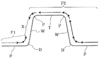
이것은 천판부 (T) 에서 장력의 평형이 일어나도록 금형 형상을 설계하고 있기 때문이다. 펀치 숄더 필릿부 (P) 를 형성하는 펀치 (2) 의 숄더부 (굽힘 반경 R1, R2 을 갖는 부분) 및 다이 숄더 필릿부 (D) 를 형성하는 다이 (4) 의 숄더부 (굽힘 반경 R3, R4 를 갖는 부분) 를 각각 재료가 통과하는 경우, 도 3 의 좌측에 펀치 숄더 필릿부 (R 면부) (P) 에 대해 확대하여 나타내는 바와 같이, 펀치 (2) 및 다이 (4) 의 숄더부에는 2 개 지점의 R 정지 부분 (E) 이 있으며, 그것들 R정지 부분 (E) 에서 재료는, 도 5 에 나타내는 바와 같이, 굽힘 변형 (B) 과 굽힘 되돌림 변형 (BR) 에 수반하는 저항 (굽힘·굽힘 되돌림 저항) 을 받는다.This is because the mold shape is designed so that tension balance occurs in the top plate T. The shoulder portion (the portion having the bending radii R1 and R2) of the
또, 펀치 숄더 필릿부 (P) 와 펀치 숄더부가 접촉하는 부분에서는, 재료는 펀치 (2) 의 숄더부로부터 마찰 저항을 받는다. 플랜지부 (F) 를 형성하는 부분이나 세로벽부 (W) 를 형성하는 부분을 통과하는 재료는, 도 5 에 나타내는 바와 같이, 블랭크 홀더 (1), 펀치 (2) 및 다이 (4) 중 어느 것과의 접촉으로 마찰에 의한 유입 저항 (DR) 을 받는다. 금형에 비드나 엠보스 등의 형상이 있는 경우에는 그 형상을 따라 재료가 변형되는 저항력이 발생한다. 또한, 플랜지부 (F) 에 수축 플랜지 변형이 일어나는 경우에는, 재료가 플랜지부 (F) 로부터 세로벽부 (W) 에 유입될 때에 축소 변형이 발생하기 때문에, 유입 저항이 증가한다. 이것들 저항이 평형을 이루는 위치 (X) 가 천판부 (T) 에 있기 때문에, 천판부 (T) 로부터의 재료 유출은 적고, 플랜지부 (F) 로부터 우선적으로 재료가 세로벽부 (W) 로 이동하게 된다.In the portion where the punch shoulder fillet portion P and the punch shoulder portion are in contact with each other, the material is subjected to frictional resistance from the shoulder portion of the
본 발명자는 이 장력의 평형 위치 (X) 를 바꿈으로써 연신 플랜지 변형에 의한 균열이나 수축 플랜지 변형에 의한 주름을 완화시키도록 재료를 이동시킬 수 있는 것은 아닐까 착상하고, 이것을 검토하였다. 그 결과, 어느 위치에 대해 일방의 저항의 합계를 F1, 타방의 저항의 합계를 F2 로 하면, F1 과 F2 가 동등해지도록 금형 형상이나 마찰 저항을 정함으로써, 평형 위치 (X) 를 자유롭게 결정할 수 있는 것을 알아내었다.The present inventor has conceived that the material can be moved so as to mitigate the wrinkles due to the deformation of the stretched flange or the deformation due to the contraction flange deformation by changing the equilibrium position X of the tensile force. As a result, if the sum of the resistances of one side is F1 and the sum of the other resistors is F2 at any position, the balance shape X can be determined freely by determining the shape of the mold and the frictional resistance so that F1 and F2 are equal I found out.
도 6 은, 본 발명의 일 실시형태의 드로 성형 방법에 의한 드로 성형시의 재료의 이동 상태를 예시하는 단면도이다. 이 도 6 에 나타내는 바와 같이, 평판상의 블랭크로부터, 도 3 에 나타내는 바와 같은, 모자형 또는 コ 자형의 단면 형상을 가짐과 함께, 길이 방향을 따라 폭 방향으로 만곡된 만곡부 (C) 와 그 만곡부의 양단에 연결되는 직변부 (S) 를 갖는 부품을 프레스 성형할 때, 실시형태의 드로 성형 방법에 따라 평형 위치 (X) 를 천판부 (T) 로부터 이동시키기 위해서는, 이하와 같은 방법을 사용할 수 있다.6 is a cross-sectional view illustrating a moving state of a material during draw forming by a draw forming method according to an embodiment of the present invention. As shown in Fig. 6, the flat blank has a hat-shaped or a U-shaped cross-sectional shape as shown in Fig. 3, and also has a curved portion C curved in the width direction along the longitudinal direction, In order to move the balance position X from the top plate portion T in accordance with the draw forming method of the embodiment when the component having the straight side portion S connected to both ends is press molded, the following method can be used .
본 실시형태의 드로 성형 방법에서는, 예를 들어 도 4 에 나타내는 구조의 금형을 사용하여, 도 3 에 나타내는 바와 같은, 모자형 또는 コ 자형의 단면 형상을 가짐과 함께, 길이 방향을 따라 폭 방향으로 만곡된 만곡부 (C) 와 그 만곡부의 양단에 연결되는 직변부 (S) 를 갖는 부품을 프레스 성형할 때, 먼저, 굽힘 반경을 크게 하면 굽힘·굽힘 되돌림 저항을 낮출 수 있으므로, 펀치 (2) 의 숄더부의 굽힘 반경 R1, R2 를, 다이 (4) 의, 도 6 의 좌측의 F1 측에 위치하는, 도 4 에서는 좌측의 숄더부의 굽힘 반경 R3 의 1.1 ∼ 10 배로 함으로써, 평형 위치 (X) 를 천판부 (T) 로부터 이동시키기 쉽게 할 수 있다.In the draw forming method of the present embodiment, for example, a die having a structure shown in Fig. 4 is used to have a hat or a U-shaped cross-sectional shape as shown in Fig. 3, When a component having a curved bent portion C and a straight side portion S connected to both ends of the bent portion is first press-molded, if the bending radius is increased, the bending / bending return resistance can be lowered. By setting the bending radii R1 and R2 of the shoulder portion to 1.1 to 10 times the bending radius R3 of the left shoulder portion in Fig. 4, which is located on the F1 side of the die 4 on the left side in Fig. 6, So that it can be easily moved from the portion T.
여기서 또한, 도 6 의 우측의 F2 측의 유입 저항을 작게 하는 방법이나, 도 6 의 좌측의 F1 측의 플랜지부 (F) 로부터의 유입 저항을 늘리는 방법도 사용함으로써, 평형 위치 (X) 는 세로벽부 (W) 로 이동한다. F2 측의 유입 저항을 작게 하는 방법으로는, 다이 (4) 의, 도 6 의 우측의 F2 측에 위치하는, 도 4 에서는 우측의 숄더부의 굽힘 반경 R4 를, 다이 (4) 의, 도 6 의 좌측의 F1 측에 위치하는, 도 4 에서는 좌측의 숄더부의 굽힘 반경 R3 보다 1.1 ∼ 10 배로 크게 하는 방법이나, 블랭크 홀더 (1) 와 다이 (4) 로, 도 6 의 우측의 F2 측의 플랜지부 (F) 를 약하게 누름으로써 마찰 저항을 낮추는 방법 등이 있다.Here, by using a method of reducing the inflow resistance on the right side F2 side in Fig. 6 or a method of increasing the inflow resistance from the flange portion F on the left side in Fig. 6, And moves to the wall portion (W). In order to reduce the inflow resistance on the F2 side, the bending radius R4 of the right shoulder of the die 4, which is located on the F2 side on the right side of Fig. 6, In Fig. 4, the bending radius R3 of the left shoulder is set to be 1.1 to 10 times larger than the bending radius R3 of the left side, and the
한편, F1 측의 유입 저항을 늘리는 방법으로는, 블랭크 홀더 (1) 나 다이 (4) 에 형성하는 도시되지 않은 비드나 엠보스 등을, 도 6 의 좌측의 F1 측의 플랜지부 (F) 에 형성하는 비드나 엠보스 등에서는, 도 6 의 우측의 F2 측의 플랜지부 (F) 에 형성하는 비드나 엠보스 등보다 굽힘 반경이 작은 형상으로 하거나, 블랭크 홀더 (1) 나 다이 (4) 의, 도 6 의 좌측의 F1 측의 플랜지부 (F) 를 끼우는 부분에만 도시되지 않은 비드나 엠보스 등을 형성하거나 하는 방법이나, 평형 위치 (X) 에 있어서의 세로벽부 (W) 를 그 세로벽부 (W) 의 벽면에 대한 수직 방향으로 만곡시킴으로써 플랜지부 (F) 에 억지로 수축 플랜지 변형을 일으켜 축소 저항을 발생시키는 방법, 블랭크 홀더 (1) 와 다이 (4) 로 F1 측의 플랜지부 (F) 를 강하게 누름으로써 마찰 저항을 높이는 방법 등이 있다. 상기 복수의 방법을 조합하여 사용함으로써, 보다 평형 위치 (X) 는 이동시키기 쉬워진다.On the other hand, as a method of increasing the inflow resistance of the F1 side, unillustrated beads and embosses formed on the
또한, 굽힘 반경을 1.1 ∼ 10 배로 하는 것이 바람직한 이유는, 1.1 배 미만에서는 저항의 차가 작기 때문에 평형 위치 (X) 가 이동하기 어렵고, 10 배보다 크게 하면 예비 형상의 상기 필릿부를 소정 형상의 상기 필릿부로 리스트라이크 가공할 때의 재료의 변형량이 커지기 때문에, 재료의 연성이 부족하여 균열이 발생할 가능성이 높아지기 때문이다.The reason why it is preferable to set the bending radius to 1.1 to 10 times is that if the difference is less than 1.1 times, the balance position X is difficult to move because the difference in resistance is small. If the bending radius is larger than 10 times, This is because the amount of deformation of the material at the time of block-like processing becomes large, so that the ductility of the material is insufficient and the possibility of occurrence of cracks increases.
상기 서술한 본 실시형태의 드로 성형 방법에서, 펀치 (2) 의 숄더부나 다이 (4) 의 숄더부의 굽힘 반경을 소정의 부품 형상보다 크게 하여 예비 형상의 부품을 프레스 성형하는 경우에는, 그 예비 형상의 부품을 그 후에 폼 성형이나 드로 성형으로 리스트라이크 가공함으로써, 부품의 필릿부 (P) 나 필릿부 (D) 의 굽힘 반경을 작게 재성형하여, 소정 반경의 필릿부를 구비하는 부품을 제조할 수 있다.In the above-described draw forming method of the present embodiment, when a preliminary shape component is formed by press forming the shoulder portion of the
또, 상기 드로 성형 혹은 그 후의 리스트라이크 가공으로는 소정의 윤곽 형상이 얻어지지 않는 경우에는, 추가로 그 후, 혹은 리스트라이크 가공과 함께, 윤곽 형상을 소정 형상으로 하는 트림 가공을 실시함으로써, 소정 윤곽 형상을 갖는 부품을 제조할 수 있다.When the predetermined contour shape can not be obtained by the draw molding or the subsequent list-like machining, a trim process is performed to further form the outline shape into a predetermined shape, A component having an outline shape can be manufactured.
평형 위치 (X) 는, 대상 부품의 드로 성형의 실험, 또는 유한 요소법에 의한 수치 해석을 실시함으로써 구할 수 있다. 또한, 굽힘·굽힘 되돌림 저항의 영향은, 마찰 저항이나 플랜지부 (F) 의 축소 저항의 영향보다 크기 때문에, 간이적으로는 굽힘·굽힘 되돌림 저항이 세로벽부 (W) 나 플랜지부 (F) 에서 평형을 이루도록 부품 형상을 결정해도 된다.The equilibrium position X can be obtained by experimenting with draw forming of the target part or numerical analysis by the finite element method. Since the influence of the bending and bending return resistance is greater than the influence of the frictional resistance and the reduction resistance of the flange portion F, the bending and bending back resistance is simplified, The component shape may be determined so as to be balanced.
굽힘·굽힘 되돌림 저항 (Fb) 은, 재료의 항복 강도 σe 와, 판 두께 t 와, 굽힘 반경 R 를 사용한 이하의 수식으로부터 산출할 수 있다.The bending and bending return resistance Fb can be calculated from the following equation using the yield strength sigma e of the material, the plate thickness t, and the bending radius R. [
Fb = σe × t/(2*(0.5*t + R))Fb =? E × t / (2 * (0.5 * t + R))
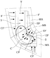
본 발명자는 평형 위치 (X) 를 결정하는 상기 방법을 발견한 것에 의해, 도 7 에 나타내는 바와 같이, 연신 플랜지 변형과 수축 플랜지 변형의 일방 혹은 양방을 억제하기 위한 이상적인 재료의 움직임을 발생시키는 방법을 알아낼 수 있었다.The inventor of the present invention has found the above method of determining the equilibrium position (X). As a result, as shown in Fig. 7, a method of generating an ideal material movement for suppressing one or both of the stretching flange deformation and the contraction flange deformation I could find out.
이 방법은, 적어도, 성형하는 부품의 폭 방향으로 세로벽부 (W) 가 만곡된 중앙부의 만곡부 (C) 의 양단에 연결되는 직변부 (S) 에서, 연신 플랜지 변형 (EF) 측의 세로벽부 (W) 혹은 그 세로벽부 (W) 와 플랜지부 (F) 사이의 필릿부에 평형 위치 (X) 를 정하여 재료 이동 패턴 MA 를 발생시킨다. 또한, 더욱 중앙부의 만곡부 (C) 에서, 수축 플랜지 변형 (CF) 측의 세로벽부 (W) 혹은 그 세로벽부 (W) 와 플랜지부 (F) 사이의 필릿부에 평형 위치 (X) 를 정하여 재료 이동 패턴 MB 를 발생시키면 바람직하다.This method is characterized in that at least a portion of a vertical wall portion (EF) side of a stretched flange deformation (EF) side at a straight side portion (S) connected to both ends of a central portion curved portion (C) W or a fillet portion between the vertical wall portion W and the flange portion F to form a material movement pattern MA. In the curved portion C of the central portion, a balance position X is defined on the vertical wall portion W on the contraction flange deformation CF side or the fillet portion between the vertical wall portion W and the flange portion F, It is preferable to generate the movement pattern MB.
통상적인 드로 성형에서는 플랜지부 (F) 로부터의 재료 유입이 억제되면 펀치 (2) 의 숄더부나 다이 (4) 의 숄더부에서의 성형이 어려워지지만, 본 실시형태에서는 천판부 (T) 로부터의 재료 유출이 있기 때문에 펀치 (2) 의 숄더부나 다이 (4) 의 숄더부에서의 성형은 완화된다.It is difficult to form the shoulder portion of the
재료 이동 패턴 MA 에서는, 도 7 에서는 좌측의 수축 플랜지 변형 (CF) 측의 플랜지부 (F) 나 세로벽부 (W), 펀치 숄더 필릿부 (P) 에서의 재료 이동이 증가하기 때문에, 만곡부 (C) 의 도 7 에서는 좌측의 수축 플랜지 변형 (CF) 측의 플랜지부 (F) 는 인장 변형을 받는다. 반대로, 재료 이동 패턴 MA 의 도 7 에서는 우측의 연신 플랜지 변형 (EF) 측의 플랜지부 (F) 로부터의 재료 이동은 감소하기 때문에, 만곡부 (C) 의 도 7 에서는 우측의 연신 플랜지 변형 (EF) 측의 플랜지부 (F) 가 인장되기 어려워진다.In the material movement pattern MA, since the material movement in the flange portion F, the vertical wall portion W and the punch shoulder fillet portion P on the contraction flange deformation CF side on the left side in Fig. 7 increases, 7, the flange portion F on the side of the contraction flange deformation CF on the left side is subjected to tensile deformation. 7 of the curved portion C is reduced because the material movement from the flange portion F on the right side stretch flange deformation EF side in the material movement pattern MA in Fig. The flange portion F on the side of the flange portion becomes difficult to be pulled.
재료 이동 패턴 MB 에서는, 만곡부 (C) 의 만곡 형상을 따른 원주 방향으로 재료를 끌어들이면서 도 7 에서는 우측의 연신 플랜지 변형 (EF) 측의 플랜지부 (F) 나 세로벽부 (W), 천판부 (T) 의 재료가 도 7 에서는 좌측의 수축 플랜지 변형 (CF) 측으로 크게 이동하기 때문에, 연신 플랜지 변형이 완화된다. 또, 수축 플랜지 변형 (CF) 측의 플랜지부 (F) 로의 재료 이동이 적어지므로, 수축 플랜지 변형의 발생이 억제된다.In the material movement pattern MB, the material is drawn in the circumferential direction along the curved shape of the curved portion C while the flange portion F and the vertical wall portion W on the extension flange deformation EF side on the right side in Fig. 7, The deformation of the elongated flange is alleviated because the material of the material T moves to the contraction flange deformation CF side on the left side in Fig. Further, since the material movement to the flange portion F on the side of the contraction flange deformation CF is small, the occurrence of contraction flange deformation is suppressed.
본 실시형태의 프레스 성형 방법에 의하면, 모자형의 단면 형상을 갖는 폭 방향으로 만곡된 부품뿐만 아니라, 플랜지부 (F) 에 위치하는 재료를 모두 세로벽부 (W) 의 성형에 사용함으로써, コ 자형의 횡단면 형상을 갖는 폭 방향으로 만곡된 부품도 성형할 수 있다.According to the press forming method of the present embodiment, not only the part bent in the width direction having the hat-shaped cross section but also the material located in the flange portion F are used for forming the vertical wall portion W, It is also possible to form a part curved in the width direction having the cross-sectional shape of Fig.
블랭크의 소재로 하는 금속판은, 인장 강도가 440 ∼ 1470 ㎫ 인 것이 바람직하다. 인장 강도가 440 ㎫ 미만인 금속판은, 연성이나 드로잉 성형성이 우수하기 때문에, 본 실시형태의 드로 성형 방법을 사용하는 이점이 적다. 또, 1470 ㎫ 을 초과하는 금속판은, 연성이 부족하기 때문에, 본 실시형태의 드로 성형 방법에서는 대상으로 하고 있지 않은 펀치 (2) 의 숄더부나 다이 (4) 의 숄더부에서의 균열이 발생하기 쉬워져, 부품의 드로 성형이 곤란해질 가능성이 있다.The metal plate used as the blank material preferably has a tensile strength of 440 to 1470 MPa. The metal plate having a tensile strength of less than 440 MPa is excellent in ductility and drawing moldability, and thus has a small advantage of using the draw forming method of the present embodiment. Further, since the metal plate having a thickness of more than 1470 MPa is insufficient in ductility, the shoulder portion of the
표 1 은, 270, 440, 980, 1180 및 1470 ㎫ 급 강판의 각종 사양을 나타내고 있다. 또, 표 2 는, 표 1 에 나타내는 270, 440, 980, 1180 및 1470 ㎫ 급 강판을 공시재로서 사용하고, 도 1 ∼ 3 에 나타내는 모자 단면 형상의 부품을 사용하여, 종래법에 의한 비교예와 본 실시형태의 방법에 의한 실시예로 검증을 실시한 결과를 나타낸다.Table 1 shows various specifications of steel sheets 270, 440, 980, 1180 and 1470 MPa. In Table 2, the steel plates 270, 440, 980, 1180 and 1470 MPa shown in Table 1 were used as the specimen and the parts having the hat cross-sectional shapes shown in Figs. 1 to 3 were used. And the result of the verification by the embodiment of the method of the present embodiment.
평형 위치 (X) 를 변화시키기 때문에, 필릿부의 반경을, 만곡부 (C) 에서는 표 3, 만곡부에 연결되는 직변부 (S) 에서는 표 4 와 같이 하였다. 여기서, 펀치 숄더와 다이 숄더의 필릿부 중, 수축 플랜지 변형 (CF) 에 가까운 쪽의 반경을 각각 R1 및 R3, 연신 플랜지 변형 (EF) 에 가까운 쪽의 반경을 각각 R2 및 R4 로 하였다. 비드에는 굽힘 반경이 8 ㎜ 인 라운드 비드를 사용하였다.Table 3 shows the radius of the fillet portion in Table 3 and Table 4 shows the radius of the fillet portion in the straight portion S connected to the curved portion. Here, the radii of the fillet portions of the punch shoulder and the die shoulder close to the contraction flange deformation CF are R1 and R3, respectively, and the radii of the fillet portion closer to the elongation flange deformation EF are R2 and R4, respectively. Round beads with a bending radius of 8 mm were used for the beads.
또한, 상기 검증에서 수축 플랜지 변형 (CF) 을 사용하여 재료 이동 패턴 MA 를 발생시키는 경우에는, 도 8 에 나타내는 바와 같은, 수축 플랜지 변형 (CF) 을 일으키는 부가 만곡부 (AC) 가 직변부 (S) 에 추가로 연결되는 부품 형상을 사용하고 있으며, 이번 실시예에서는, 그 수축 플랜지 변형 (CF) 을 일으키는 부가 만곡부 (AC) 의 세로벽을 곡률 반경 200 ㎜ 의 만곡 형상으로 하였다. 단, 재료 이동 패턴 MA 를 발생시키는 형상은, 특별히 이 형상에 한정되는 것은 아니다.When the material movement pattern MA is generated using the contraction flange deformation CF in the above verification, the additional curved portion AC causing the contraction flange deformation CF, as shown in Fig. 8, In this embodiment, the vertical wall of the additional curved portion AC causing the contraction flange deformation CF has a curved shape with a radius of curvature of 200 mm. However, the shape for generating the material movement pattern MA is not particularly limited to this shape.


종래법은 평형 위치 (X) 가 천판부 (T) 가 되는 일반적인 드로 성형으로 하였다. 성형품의 평가는 육안으로 실시하여, 플랜지부에 발생한 주름과 균열에 대해 각각 표 5 와 표 6 에 나타내는 기준에 의해 ○, △, × 의 3 단계로 평가하였다.The conventional method is a general draw forming in which the balance position X is the top plate T. Evaluation of the molded article was carried out by naked eye, and wrinkles and cracks occurring in the flange portion were evaluated in three stages of?,?, And x according to the criteria shown in Tables 5 and 6, respectively.


검증의 결과, 270 ㎫ 급 강판에서는 종래의 드로 성형 방법에서도 본 실시형태의 드로 성형 방법에서도 주름이나 균열이 발생하지 않고 성형할 수 있었다. 440 ㎫ 이상의 강판의 경우, 종래의 드로 성형 방법에서는 현저한 균열과 주름이 발생하였지만, 본 실시형태의 드로 성형 방법에서는 균열과 주름의 발생을 방지할 수 있었다.As a result of the verification, it was possible to form the steel sheet of 270 MPa in the conventional draw forming method without wrinkles or cracks even in the draw forming method of the present embodiment. In the case of a steel sheet of 440 MPa or more, significant cracks and wrinkles occurred in the conventional draw forming method, but cracks and wrinkles could be prevented in the draw forming method of the present embodiment.
이상, 도시예에 기초하여 설명하였지만, 본 발명은 상기 서술한 예에 한정되는 것은 아니고, 특허청구범위의 기재 범위 내에서 적절히 변경할 수 있으며, 예를 들어 드로 성형에 사용하는 금형은, 도 4 에 나타내는 구조를 대신하여, 다이 (4) 를 좌우의 숄더부와 오목부에서 다른 부재로 한 구조의 것으로 하거나, 펀치 (2) 의 숄더부의 굽힘 반경을 크게 하여 좌우의 필릿부 (P) 의 상단부가 곡면상의 천판부 (T) 와 연결되도록 드로 성형하는 것으로 하거나 할 수도 있다.The present invention is not limited to the example described above and can be suitably changed within the scope of the claims. For example, a mold used for draw forming is as shown in Fig. 4 It is also possible to adopt a structure in which the die 4 is made of a member different from the left and right shoulder portions and the concave portion or that the shoulder portion of the
산업상 이용가능성Industrial availability
이렇게 하여 본 발명의 프레스 성형 방법 및 그 프레스 성형 방법을 사용한 부품의 제조 방법 그리고 그 프레스 성형 방법을 사용하여 제조된 부품에 의하면, 평판상의 블랭크로부터, 모자형 또는 コ 자형의 단면 형상을 가짐과 함께, 길이 방향을 따라 폭 방향으로 만곡된 만곡부와 그 만곡부의 양단에 연결되는 직변부를 갖는 부품을 프레스 성형할 때에, 천판부와, 그 천판부의 양측 단부에 필릿부를 개재하여 상단부가 연결되는 세로벽부와, 그것들 세로벽부의 하단부에 필릿부를 개재하여 내측 단부가 연결되는 플랜지부를 구비하는 모자형의 단면 형상을 거쳐 모자형 또는 コ 자형의 단면 형상으로 드로 성형하고, 그 드로 성형시에, 만곡부의 플랜지부에 발생하는 둘레 방향의 인장 변형 혹은 둘레 방향의 압축 변형을 완화시키는 만곡부의 플랜지부로의 재료 이동을 일으키게 하므로, 수축 플랜지 변형에 의한 주름의 발생과 연신 플랜지 변형에 의한 균열의 발생의 일방 또는 양방을 억제할 수 있다.According to the press forming method, the method of manufacturing a part using the press forming method of the present invention, and the parts manufactured by using the press forming method of the present invention, it is possible to form a hat- A vertical wall portion to which upper ends are connected via fillet portions to both side end portions of the top plate portion when press-molding a component having a curved portion curved in the width direction along the longitudinal direction and a side portion connected to both ends of the curved portion, And a flange portion to which an inner end portion is connected via a fillet portion to a lower end portion of the vertical wall portion, the die is formed into a hat-like or a U-shaped cross-sectional shape through a hat-shaped cross-sectional shape, The flange portion of the curved portion that alleviates tensile deformation in the circumferential direction or compressive deformation in the circumferential direction generated in the flange portion It is possible to suppress one or both of the occurrence of wrinkles due to the contraction flange deformation and the occurrence of cracks due to the deformation of the drawn flange.
1 : 블랭크 홀더
2 : 펀치
3 : 하형
4 : 다이
5 : 상형
6 : 쿠션핀
C : 만곡부
CF : 수축 플랜지 변형
D : 다이 숄더 필릿부
EF : 연신 플랜지 변형
F : 플랜지부
P : 펀치 숄더 필릿부
R1 ∼ R4 : 굽힘 반경
S : 직변부
T : 천판부
W : 세로벽부
X : 평형 위치1: Blank holder
2: punch
3: Lower mold
4: Die
5: HYPER
6: Cushion pin
C: Cymbals
CF: Shrinkage flange deformation
D: die shoulder fillet portion
EF: Stretch flange deformation
F: flange portion
P: Punch shoulder fillet portion
R1 to R4: Bending radius
S: straight edge
T: Top plate
W: vertical wall portion
X: Equilibrium position
Claims (10)
천판부와, 그 천판부의 양측 단부에 필릿부를 개재하여 상단부가 연결되는 세로벽부와, 그것들 세로벽부의 하단부에 필릿부를 개재하여 내측 단부가 연결되는 플랜지부를 구비하는 모자형의 단면 형상을 거쳐 모자형 또는 コ 자형의 단면 형상으로 드로 성형하고,
그 드로 성형시에, 상기 만곡부의 상기 플랜지부에 발생하는 둘레 방향의 인장 변형 혹은 둘레 방향의 압축 변형을 완화시키는 상기 만곡부의 상기 플랜지부의 재료 이동을 일으키게 하는 것을 특징으로 하는 프레스 성형 방법.When press-molding a part having a hat-like or U-shaped cross-sectional shape from a flat plate-like blank and having a curved portion curved in the width direction along the longitudinal direction and a side portion connected to both ends of the curved portion,
And a flange portion having an inner end connected to the lower end portion of the vertical wall portion through a fillet portion, through a hat-shaped cross-sectional shape, the cap having a top plate portion, Shaped or a U-shaped cross-sectional shape,
And causing material movement of the flange portion of the curved portion that alleviates tensile deformation in the circumferential direction or compressive deformation in the circumferential direction occurring in the flange portion of the curved portion during the die forming.
상기 만곡부의 상기 플랜지부에 발생하는 둘레 방향의 인장 변형 혹은 압축 변형을 완화시키는 상기 만곡부의 상기 플랜지부의 재료 이동을 일으키게 하기 위해, 상기 직변부에서의 재료 유입량의 평형 위치를 상기 만곡부에서의 연신 플랜지 변형측의 상기 세로벽부, 혹은 그 세로벽부와 상기 플랜지부 사이의 상기 필릿부로 하여, 상기 직변부에서의 수축 플랜지 변형부측으로부터의 재료 유입을, 상기 천판부를 넘을 정도로 증가시키는 프레스 성형 방법.The method according to claim 1,
In order to cause material movement of the flange portion of the curved portion that alleviates tensile deformation or compressive deformation in the circumferential direction generated in the flange portion of the curved portion, an equilibrium position of the inflow amount of the material in the straightened portion is set to an elongation The fillet portion between the vertical wall portion on the side of the flange deformation or the filler portion between the vertical wall portion and the flange portion so as to increase the inflow of the material from the side of the shrink flange deformation portion in the straight portion to an extent exceeding the top plate portion.
상기 만곡부의 상기 플랜지부에 발생하는 둘레 방향의 인장 변형 혹은 압축 변형을 완화시키는 상기 만곡부의 상기 플랜지부의 재료 이동을 일으키게 하기 위해, 상기 만곡부에서의 재료 유입량의 평형 위치를 수축 플랜지 변형측의 상기 세로벽부, 혹은 그 세로벽부와 상기 플랜지부 사이의 상기 필릿부로 하여, 상기 만곡부에서의 수축 플랜지 변형부측으로부터의 재료 유입을 억제함과 함께 연신 플랜지 변형측으로부터의 재료 유입을, 상기 천판부를 넘을 정도로 증가시키는 프레스 성형 방법.3. The method according to claim 1 or 2,
In order to cause material movement of the flange portion of the curved portion that alleviates tensile deformation or compressive deformation in the circumferential direction generated in the flange portion of the curved portion, an equilibrium position of the inflow amount of the material in the curved portion The fillet portion between the vertical wall portion or the vertical wall portion and the flange portion prevents the inflow of the material from the contraction flange deformation portion side in the curved portion and prevents the inflow of the material from the stretch flange deformation side to the upper side .
상기 단면 형상에 있어서, 상기 천판부와 상기 세로벽부 사이의 상기 필릿부의 굽힘 반경을, 상기 세로벽부와 상기 플랜지부 사이의 상기 필릿부의 굽힘 반경의 1.1 ∼ 10 배로 하는 것을 특징으로 하는 프레스 성형 방법.4. The method according to any one of claims 1 to 3,
Wherein the bending radius of the fillet portion between the top plate portion and the vertical wall portion is set to 1.1 to 10 times the bending radius of the fillet portion between the vertical wall portion and the flange portion in the cross sectional shape.
상기 단면 형상에 있어서, 상기 천판부와 상기 세로벽부 사이의 상기 필릿부에서, 상기 평형 위치에서 먼 쪽의 필릿부의 굽힘 반경을, 상기 평형 위치에서 가까운 쪽의 필릿부의 굽힘 반경보다 크게 하는 것을 특징으로 하는 프레스 성형 방법.5. The method according to any one of claims 1 to 4,
The bending radius of the fillet portion farther from the balance position in the fillet portion between the top plate portion and the vertical wall portion is made larger than the bending radius of the fillet portion near the balance position. .
상기 단면 형상에 있어서, 상기 평형 위치에서 가까운 쪽에서, 상기 플랜지부에 비드를 형성하는 것을 특징으로 하는 프레스 성형 방법.6. The method according to any one of claims 1 to 5,
Wherein a bead is formed in the flange portion at a side closer to the equilibrium position in the sectional shape.
상기 단면 형상에 있어서, 상기 평형 위치에서 가까운 쪽에서, 상기 세로벽부에 만곡 형상을 형성하는 것을 특징으로 하는 프레스 성형 방법.7. The method according to any one of claims 1 to 6,
Wherein a curved shape is formed in the vertical wall portion at a side closer to the equilibrium position in the sectional shape.
상기 블랭크에 인장 강도가 440 ∼ 1470 ㎫ 인 금속판을 사용하는 것을 특징으로 하는 프레스 성형 방법.8. The method according to any one of claims 1 to 7,
And a blank having a tensile strength of 440 to 1470 MPa is used as the blank.
Applications Claiming Priority (3)
| Application Number | Priority Date | Filing Date | Title |
|---|---|---|---|
| JP2015060113 | 2015-03-31 | ||
| JPPCT/JP2015/060113 | 2015-03-31 | ||
| PCT/JP2016/052555 WO2016157976A1 (en) | 2015-03-31 | 2016-01-29 | Press molding method, method for manufacturing component in which said press molding method is used, and component manufactured using said press molding method |
Publications (2)
| Publication Number | Publication Date |
|---|---|
| KR20170120156A true KR20170120156A (en) | 2017-10-30 |
| KR101979528B1 KR101979528B1 (en) | 2019-05-16 |
Family
ID=57005643
Family Applications (1)
| Application Number | Title | Priority Date | Filing Date |
|---|---|---|---|
| KR1020177026798A KR101979528B1 (en) | 2015-03-31 | 2016-01-29 | Press-forming method, method of manufacturing component with the press-forming method |
Country Status (7)
| Country | Link |
|---|---|
| US (1) | US10603707B2 (en) |
| EP (1) | EP3278897B1 (en) |
| JP (1) | JP6028956B1 (en) |
| KR (1) | KR101979528B1 (en) |
| CN (1) | CN107405668B (en) |
| MX (1) | MX2017012499A (en) |
| WO (1) | WO2016157976A1 (en) |
Families Citing this family (16)
| Publication number | Priority date | Publication date | Assignee | Title |
|---|---|---|---|---|
| CN111867747B (en) * | 2018-02-28 | 2022-05-13 | 杰富意钢铁株式会社 | Metal plate for press molding, press molding device, and method for manufacturing press member |
| JP6973236B2 (en) * | 2018-03-29 | 2021-11-24 | Jfeスチール株式会社 | Press molding method |
| CN112154036B (en) * | 2018-05-24 | 2023-04-04 | 杰富意钢铁株式会社 | Method for manufacturing stamped member |
| US20210379639A1 (en) * | 2018-10-31 | 2021-12-09 | Jfe Steel Corporation | Press formed component and method for manufacturing same |
| JP6677289B1 (en) * | 2018-12-12 | 2020-04-08 | Jfeスチール株式会社 | Press molding method |
| CN113286672B (en) * | 2019-01-11 | 2023-04-21 | 杰富意钢铁株式会社 | Press molding method, blanking of plate-like material, intermediate molded article, method for producing press molded article, and press molded article |
| CN112916707B (en) * | 2019-11-20 | 2023-06-06 | 上海赛科利汽车模具技术应用有限公司 | Part forming method for preventing stretching modeling vertical face from cracking and wrinkling |
| JP7359707B2 (en) | 2020-01-28 | 2023-10-11 | フタバ産業株式会社 | Press-formed product manufacturing method and press-formed product manufacturing device |
| JP7364905B2 (en) | 2020-03-31 | 2023-10-19 | 日本製鉄株式会社 | Sheet metal molded product manufacturing method, sheet metal molded product manufacturing device, and flange up tool |
| JP6897840B1 (en) * | 2020-04-09 | 2021-07-07 | Jfeスチール株式会社 | Press molding method |
| MX2022012137A (en) | 2020-04-09 | 2022-10-18 | Jfe Steel Corp | Press-forming method and press-formed product. |
| JP6897841B1 (en) * | 2020-04-09 | 2021-07-07 | Jfeスチール株式会社 | Press molded product |
| JP7156343B2 (en) * | 2020-07-29 | 2022-10-19 | Jfeスチール株式会社 | Press molding method and press molding die |
| JP6966729B1 (en) | 2020-11-25 | 2021-11-17 | Jfeスチール株式会社 | Press molded product |
| JP7006759B1 (en) | 2020-11-25 | 2022-01-24 | Jfeスチール株式会社 | Press molding method |
| CN114011960A (en) * | 2021-09-27 | 2022-02-08 | 深圳市信维通信股份有限公司 | Deep drawing and stamping forming process for L-shaped profile thin metal shell |
Citations (5)
| Publication number | Priority date | Publication date | Assignee | Title |
|---|---|---|---|---|
| JPH0544322U (en) * | 1991-11-15 | 1993-06-15 | 富士重工業株式会社 | Press mold |
| JP2010227995A (en) | 2009-03-30 | 2010-10-14 | Kobe Steel Ltd | Method of forming curved channel member |
| JP2014039957A (en) | 2012-07-27 | 2014-03-06 | Nisshin Steel Co Ltd | Press working method of flanged molding member, and bending tool for use in the method |
| WO2014106932A1 (en) | 2013-01-07 | 2014-07-10 | 新日鐵住金株式会社 | Press component and method and device for manufacturing same |
| JP2014240078A (en) * | 2013-06-11 | 2014-12-25 | Jfeスチール株式会社 | Press forming method |
Family Cites Families (12)
| Publication number | Priority date | Publication date | Assignee | Title |
|---|---|---|---|---|
| JPS5976625A (en) | 1982-10-26 | 1984-05-01 | Toyota Motor Corp | Working die for bending curved flange |
| JP4160501B2 (en) | 2003-12-26 | 2008-10-01 | 独立行政法人科学技術振興機構 | Wrinkle suppression force distribution control device for plate press forming |
| JP4879588B2 (en) * | 2006-01-19 | 2012-02-22 | 新日本製鐵株式会社 | Metal plate press molding method for automobile parts having a tensile strength of 440 MPa or more for suppressing spring back |
| WO2007093049A1 (en) * | 2006-02-13 | 2007-08-23 | Olga Ornatsky | Kinase and phosphatase assays conducted by elemental analysis |
| JP2009255524A (en) * | 2008-03-25 | 2009-11-05 | Seiko Epson Corp | Liquid jetting head and liquid jetting device |
| JP4992048B2 (en) * | 2008-04-23 | 2012-08-08 | Jfeスチール株式会社 | Press molding method for press molded parts with excellent shape freezing properties |
| JP4920649B2 (en) * | 2008-09-12 | 2012-04-18 | 新日本製鐵株式会社 | Multi-stage press forming method with excellent shape freezing |
| WO2011145679A1 (en) * | 2010-05-19 | 2011-11-24 | 新日本製鐵株式会社 | Method for press-forming l-shaped components |
| US9211579B2 (en) | 2010-11-24 | 2015-12-15 | Nippon Steel & Sumitomo Metal Corporation | Method of producing L-shaped product |
| JP5794025B2 (en) | 2011-07-29 | 2015-10-14 | Jfeスチール株式会社 | Mold design method and press molding method |
| US10220428B2 (en) * | 2013-12-20 | 2019-03-05 | Jfc Steel Corporation | Press forming method, and method for manufacturing press-formed part |
| JP6438206B2 (en) | 2014-03-25 | 2018-12-12 | キヤノン株式会社 | COMMUNICATION DEVICE, ITS CONTROL METHOD, AND PROGRAM |
-
2016
- 2016-01-29 CN CN201680017285.7A patent/CN107405668B/en active Active
- 2016-01-29 WO PCT/JP2016/052555 patent/WO2016157976A1/en active Application Filing
- 2016-01-29 KR KR1020177026798A patent/KR101979528B1/en active IP Right Grant
- 2016-01-29 JP JP2016524546A patent/JP6028956B1/en active Active
- 2016-01-29 MX MX2017012499A patent/MX2017012499A/en unknown
- 2016-01-29 US US15/561,581 patent/US10603707B2/en active Active
- 2016-01-29 EP EP16771860.0A patent/EP3278897B1/en active Active
Patent Citations (5)
| Publication number | Priority date | Publication date | Assignee | Title |
|---|---|---|---|---|
| JPH0544322U (en) * | 1991-11-15 | 1993-06-15 | 富士重工業株式会社 | Press mold |
| JP2010227995A (en) | 2009-03-30 | 2010-10-14 | Kobe Steel Ltd | Method of forming curved channel member |
| JP2014039957A (en) | 2012-07-27 | 2014-03-06 | Nisshin Steel Co Ltd | Press working method of flanged molding member, and bending tool for use in the method |
| WO2014106932A1 (en) | 2013-01-07 | 2014-07-10 | 新日鐵住金株式会社 | Press component and method and device for manufacturing same |
| JP2014240078A (en) * | 2013-06-11 | 2014-12-25 | Jfeスチール株式会社 | Press forming method |
Also Published As
| Publication number | Publication date |
|---|---|
| EP3278897A4 (en) | 2018-04-25 |
| WO2016157976A1 (en) | 2016-10-06 |
| JPWO2016157976A1 (en) | 2017-04-27 |
| MX2017012499A (en) | 2018-01-18 |
| US10603707B2 (en) | 2020-03-31 |
| CN107405668B (en) | 2020-05-05 |
| KR101979528B1 (en) | 2019-05-16 |
| US20180085811A1 (en) | 2018-03-29 |
| EP3278897A1 (en) | 2018-02-07 |
| EP3278897B1 (en) | 2021-12-15 |
| JP6028956B1 (en) | 2016-11-24 |
| CN107405668A (en) | 2017-11-28 |
Similar Documents
| Publication | Publication Date | Title |
|---|---|---|
| KR101979528B1 (en) | Press-forming method, method of manufacturing component with the press-forming method | |
| KR101779688B1 (en) | Press forming method and press forming device | |
| JP5382281B1 (en) | Press forming method | |
| JP4693475B2 (en) | Press molding method and mold used therefor | |
| CN109562427B (en) | Method for producing press-molded article | |
| KR101962557B1 (en) | Press forming method and press forming die | |
| JP5861749B1 (en) | Press forming method | |
| KR102023541B1 (en) | Method for manufacturing stretch-flange-formed component | |
| JP6249132B2 (en) | Press molded product production line | |
| JP6512191B2 (en) | Method of designing mold and method of manufacturing press-formed product | |
| KR102215972B1 (en) | Press forming method | |
| CN108698105B (en) | Method for producing press-molded article | |
| JP6738055B2 (en) | Press-molded product design method, press-molding die, press-molded product, and press-molded product manufacturing method | |
| KR102018964B1 (en) | Press-forming method, method of manufacturing component with such a method, and press-forming apparatus | |
| KR101591874B1 (en) | Double cross pad of upper die for compensating deformation after stamping automotive structure panel and method thereof | |
| JP6036768B2 (en) | Press forming method | |
| JP6319382B2 (en) | Manufacturing method of stretch flange molded parts | |
| KR102450454B1 (en) | Press forming method | |
| JP6330766B2 (en) | Press forming method |
Legal Events
| Date | Code | Title | Description |
|---|---|---|---|
| A201 | Request for examination | ||
| E902 | Notification of reason for refusal | ||
| E701 | Decision to grant or registration of patent right |