KR20170086531A - Start-up controller for a power converter - Google Patents
Start-up controller for a power converter Download PDFInfo
- Publication number
- KR20170086531A KR20170086531A KR1020177014436A KR20177014436A KR20170086531A KR 20170086531 A KR20170086531 A KR 20170086531A KR 1020177014436 A KR1020177014436 A KR 1020177014436A KR 20177014436 A KR20177014436 A KR 20177014436A KR 20170086531 A KR20170086531 A KR 20170086531A
- Authority
- KR
- South Korea
- Prior art keywords
- controller
- voltage
- power
- transformer
- coupled
- Prior art date
Links
Images

Classifications
-
- H—ELECTRICITY
- H02—GENERATION; CONVERSION OR DISTRIBUTION OF ELECTRIC POWER
- H02M—APPARATUS FOR CONVERSION BETWEEN AC AND AC, BETWEEN AC AND DC, OR BETWEEN DC AND DC, AND FOR USE WITH MAINS OR SIMILAR POWER SUPPLY SYSTEMS; CONVERSION OF DC OR AC INPUT POWER INTO SURGE OUTPUT POWER; CONTROL OR REGULATION THEREOF
- H02M3/00—Conversion of dc power input into dc power output
- H02M3/22—Conversion of dc power input into dc power output with intermediate conversion into ac
- H02M3/24—Conversion of dc power input into dc power output with intermediate conversion into ac by static converters
- H02M3/28—Conversion of dc power input into dc power output with intermediate conversion into ac by static converters using discharge tubes with control electrode or semiconductor devices with control electrode to produce the intermediate ac
- H02M3/325—Conversion of dc power input into dc power output with intermediate conversion into ac by static converters using discharge tubes with control electrode or semiconductor devices with control electrode to produce the intermediate ac using devices of a triode or a transistor type requiring continuous application of a control signal
- H02M3/335—Conversion of dc power input into dc power output with intermediate conversion into ac by static converters using discharge tubes with control electrode or semiconductor devices with control electrode to produce the intermediate ac using devices of a triode or a transistor type requiring continuous application of a control signal using semiconductor devices only
- H02M3/33538—Conversion of dc power input into dc power output with intermediate conversion into ac by static converters using discharge tubes with control electrode or semiconductor devices with control electrode to produce the intermediate ac using devices of a triode or a transistor type requiring continuous application of a control signal using semiconductor devices only of the forward type
- H02M3/33546—Conversion of dc power input into dc power output with intermediate conversion into ac by static converters using discharge tubes with control electrode or semiconductor devices with control electrode to produce the intermediate ac using devices of a triode or a transistor type requiring continuous application of a control signal using semiconductor devices only of the forward type with automatic control of the output voltage or current
-
- H—ELECTRICITY
- H02—GENERATION; CONVERSION OR DISTRIBUTION OF ELECTRIC POWER
- H02M—APPARATUS FOR CONVERSION BETWEEN AC AND AC, BETWEEN AC AND DC, OR BETWEEN DC AND DC, AND FOR USE WITH MAINS OR SIMILAR POWER SUPPLY SYSTEMS; CONVERSION OF DC OR AC INPUT POWER INTO SURGE OUTPUT POWER; CONTROL OR REGULATION THEREOF
- H02M1/00—Details of apparatus for conversion
- H02M1/36—Means for starting or stopping converters
-
- H—ELECTRICITY
- H02—GENERATION; CONVERSION OR DISTRIBUTION OF ELECTRIC POWER
- H02M—APPARATUS FOR CONVERSION BETWEEN AC AND AC, BETWEEN AC AND DC, OR BETWEEN DC AND DC, AND FOR USE WITH MAINS OR SIMILAR POWER SUPPLY SYSTEMS; CONVERSION OF DC OR AC INPUT POWER INTO SURGE OUTPUT POWER; CONTROL OR REGULATION THEREOF
- H02M3/00—Conversion of dc power input into dc power output
- H02M3/22—Conversion of dc power input into dc power output with intermediate conversion into ac
- H02M3/24—Conversion of dc power input into dc power output with intermediate conversion into ac by static converters
- H02M3/28—Conversion of dc power input into dc power output with intermediate conversion into ac by static converters using discharge tubes with control electrode or semiconductor devices with control electrode to produce the intermediate ac
- H02M3/325—Conversion of dc power input into dc power output with intermediate conversion into ac by static converters using discharge tubes with control electrode or semiconductor devices with control electrode to produce the intermediate ac using devices of a triode or a transistor type requiring continuous application of a control signal
- H02M3/335—Conversion of dc power input into dc power output with intermediate conversion into ac by static converters using discharge tubes with control electrode or semiconductor devices with control electrode to produce the intermediate ac using devices of a triode or a transistor type requiring continuous application of a control signal using semiconductor devices only
- H02M3/33507—Conversion of dc power input into dc power output with intermediate conversion into ac by static converters using discharge tubes with control electrode or semiconductor devices with control electrode to produce the intermediate ac using devices of a triode or a transistor type requiring continuous application of a control signal using semiconductor devices only with automatic control of the output voltage or current, e.g. flyback converters
- H02M3/33523—Conversion of dc power input into dc power output with intermediate conversion into ac by static converters using discharge tubes with control electrode or semiconductor devices with control electrode to produce the intermediate ac using devices of a triode or a transistor type requiring continuous application of a control signal using semiconductor devices only with automatic control of the output voltage or current, e.g. flyback converters with galvanic isolation between input and output of both the power stage and the feedback loop
Abstract
전형적으로 파워 컨버터들, 예컨대 AC/DC 및 DC/DC는 적절한 정품의 스타트-업을 위해 그리고 정확한 동작 전압 바이어스들을 개발하기 위해 고유한 회로망을 갖는다. 전형적으로 이 고유 회로망은 1차측 컨트롤러에 통합되어 있다. 이 1차측 컨트롤러는 일단 시작되면 파워 컨버터의 제어의 1차 수단일 수도 있다. 그러나, 보다 정확한 출력 전압 조정을 위해서는 전형적으로 2차측 컨트롤러가 필요하며, 2차측 컨트롤러는 1차측 컨트롤러에 이미 존재하는 회로망을 복제한다. 전형적으로 분리 장벽에 걸친 두 개의 컨트롤러들 간의 선형 통신에 의해 복잡성이 추가된다. 단순화된 1차측 스타트-업 컨트롤러는, 2차측 컨트롤러가 활성화되어 선형 신호 대신 분리 장벽을 통해 개별 PWM 명령들을 송신함으로써 제어를 획득할 때까지 컨버터에 전력을 공급하기 위해 최소한의 회로망을 제공하는 것이 예상된다. 2차측 컨트롤러에 고장이 발생하면, 스타트-업 컨트롤러는 전압 및 전류 보호 기능을 제공할 수 있다. 2차측 컨트롤러는 정교한 컨버터 제어를 위해 아날로그 및/또는 디지털 설계가 가능하다.Typically, power converters, such as AC / DC and DC / DC, have a unique network for proper genuine start-up and to develop accurate operating voltage biases. Typically, this proprietary network is integrated into the primary side controller. This primary controller may be the primary means of controlling the power converter once it is started. However, for more accurate output voltage regulation, a secondary controller is typically needed, and the secondary controller replicates a circuit already present in the primary controller. Typically, complexity is added by linear communication between two controllers across a separation barrier. A simplified primary-side start-up controller is expected to provide a minimal circuit to power the converter until the secondary controller acquires control by activating and sending individual PWM commands through a separation barrier instead of a linear signal do. If the secondary controller fails, the start-up controller can provide voltage and current protection. The secondary controller can be analog and / or digital designed for sophisticated converter control.

Description
관련 특허 출원Related patent application
본 출원은, Thomas Quigley에 의해 2014년 11월 20일 출원된 발명의 명칭이 "Start-Up AC/DC Converter"인 공동 소유의 미국 가출원 번호 62/082,317 호의 우선이익을 주장하며, 상기 미국 가출원은 모든 목적들을 위해 본 출원에 참조로 통합된다.This application claims priority benefit from commonly owned U.S. Provisional Application No. 62 / 082,317, entitled " Start-Up AC / DC Converter, " filed November 20, 2014 by Thomas Quigley, Incorporated herein by reference in its entirety for all purposes.
기술 분야Technical field
본 개시는 파워 컨버터들에 관한 것으로, 특히, DC-DC 및 AC-DC 파워 컨버터들을 위한 스타트-업 컨트롤러 방법 및 장치에 관한 것이다.The present disclosure relates to power converters, and more particularly, to start-up controller methods and apparatus for DC-DC and AC-DC power converters.
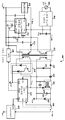
전형적으로 파워 컨버터들, 예를 들어 DC-DC 및 AC-DC는 적절한 정품의(graceful) 스타트-업(소프트 스타트)을 위해 그리고 정확한 동작 전압 바이어스들을 개발하기 위해 고유한 회로망을 갖는다. 이 고유한 회로망은 이러한 파워 컨버터들의 비용 및 납기 일정을 증가시킬 수 있는 주문형 집적 회로 및/또는 독점 설계를 필요로 할 수 있다. 도 3은 종래 기술의 플라이백(flyback) 컨버터의 개략도를 도시한다. 변압기(T1)는 1차측 바이어스 권선(302)을 갖는 것으로 도시되어 있다. 이것은 1차측 컨트롤러 디바이스(301)를 그것의 VDD 포트를 통해 바이어스하는데 사용된다. VDD 전압은 변압기 커플링을 통해 출력 전압(Vo)으로 교차 조절된다(cross-regulated). 따라서, 그것의 VDD 포트의 전압을 모니터링하는 컨트롤러(301)에 의해 Vo 전압을 조절하는 것이 가능하다. 전형적으로 컨트롤러(301)로의 변환 커플링을 사용하여 Vo를 조절하는 것은 대부분의 애플리케이션들에 대해 충분히 정확하지 않기 때문에, 플라이백 컨버터(300)의 2차측으로부터 그것의 1차측으로의 추가적인 피드백 경로가 필요하다. 전압 기준부(304)(U3)는 정밀(precision) 기준부(Vo는 해당 정밀 기준부와 비교됨), 전압 에러 증폭기(안정성을 위한 자신의 보상 요소를 구비함) 및 광학 분리 커플러(옵토커플러)(303)를 구동하기 위한 드라이버를 제공하는 디바이스이다. 컨트롤러(301)는 또한 정밀 기준부 및 전압 증폭기를 포함하지만, 이 회로들은 추가적인 피드백 경로가 포함될 때에는 이용되지 않는다. 옵토커플러(303)는 선형적으로 구동된다. 따라서 옵토커플러(303)의 전류 전달 비(current transfer ratio; CTR)가 문제된다. CTR은 추가 피드백 경로에 이득을 추가한다. 이 이득은 디바이스마다 다를 수 있으며, 디바이스의 CTR은 오래될수록 바뀔 수 있다.Typically, power converters, such as DC-DC and AC-DC, have a unique network for proper graceful start-up (soft start) and for developing accurate operating voltage biases. This unique network may require an application specific integrated circuit and / or proprietary design that can increase the cost and delivery schedules of these power converters. Figure 3 shows a schematic diagram of a prior art flyback converter. Transformer T1 is shown having primary-side bias winding 302. This is used to bias the primary
컨트롤러(301)는 플라이백 컨버터(300)의 1차측에 위치한다. 플라이백 컨버터(300)의 2차측은 부하(애플리케이션)가 결합되는 곳이다. 전형적으로, 애플리케이션 디바이스(도시되지 않음)는 프로그래밍 기능을 구비한 마이크로프로세서를 포함한다. 컨트롤러(301)는 프로그래밍이 보다 정교한 플라이백 컨버터 제어 기술을 제공할 수 있는 이점으로부터 분리되어 있다. 파워 MOSFET 스위치(Q1)는 외부 디바이스이고, 저항기(R6)는 MOSFET 스위치(Q1)를 통해 흐르는 전류와 유사한 전압을 스케일링하는 외부 저항기로 전류 감지를 위해 컨트롤러(301)에 의해 사용된다.The
따라서, 2차측 컨트롤러의 자원들을 복제하지 않고 1차측 전자 디바이스들 상의 개별 구성요소들을 최소화하는, 1차측에 종래의 저비용 집적 회로(IC) 해결책을 사용하여 파워 컨버터들을 스타트-업하기 위한 저비용 해결책이 필요하다.Thus, a low-cost solution for starting up power converters using conventional low cost integrated circuit (IC) solutions on the primary side, minimizing discrete components on the primary electronics devices without duplicating the resources of the secondary controller need.
일 실시예에 따르면, 파워 컨버터를 스타트-업하기 위한 방법은: 제 1 DC 전압을 스타트-업 컨트롤러에 인가하는 단계; 상기 스타트-업 컨트롤러에 의해 파워 스위치를 턴 온 및 오프하는 단계 - 상기 제 1 DC 전압과 상기 파워 스위치는 변압기의 1차 권선에 결합될 수 있고, 이로써 상기 변압기의 2차 권선에 AC 전압이 생성될 수 있음 -; 2차측 컨트롤러와 부하에 전력을 공급하기 위해 제 2 DC 전압을 제공하도록 제 2 정류기로 상기 변압기의 상기 2차 권선으로부터의 상기 AC 전압을 정류하는 단계; 및 상기 제 2 DC 전압이 원하는 전압 값에 있을 때 상기 스타트-업 컨트롤러로부터 상기 2차측 컨트롤러로 상기 파워 스위치의 제어를 이전하는 단계를 포함할 수 있다.According to one embodiment, a method for starting up a power converter comprises: applying a first DC voltage to a start-up controller; Turning on and off the power switch by the start-up controller, the first DC voltage and the power switch being coupled to a primary winding of the transformer, whereby an AC voltage is generated in the secondary winding of the transformer -; Rectifying the AC voltage from the secondary winding of the transformer to a second rectifier to provide a second DC voltage to power the secondary controller and the load; And transferring control of the power switch from the start-up controller to the secondary controller when the second DC voltage is at a desired voltage value.
상기 방법의 추가 실시예에 따르면, 상기 스타트-업 컨트롤러는 처음에는 상기 제 1 DC 전압으로부터 이후에는 상기 변압기의 3차 권선으로부터 직접 전력이 공급될 수 있다. 상기 방법의 추가 실시예에 따르면, 상기 스타트-업 컨트롤러에 의해 상기 파워 스위치를 턴 온 및 오프하는 단계는: 상기 변압기의 상기 1차 권선을 관통하는 최대 전류에 도달할 때까지 상기 파워 스위치를 턴 온하는 단계; 및 이후에 고정 시간 주기 동안 상기 파워 스위치를 턴 오프하는 단계를 포함할 수 있다. 상기 방법의 추가 실시예에 따르면, 상기 고정 시간 주기는 상기 스타트-업 컨트롤러에 결합된 커패시터의 커패시턴스 값에 의해 결정될 수 있다.According to a further embodiment of the method, the start-up controller can be supplied with power directly from the first DC voltage at first from the tertiary winding of the transformer thereafter. According to a further embodiment of the method, the step of turning on and off the power switch by the start-up controller comprises the steps of: turning the power switch until reaching a maximum current through the primary winding of the transformer Turning on; And then turning off the power switch for a fixed period of time. According to a further embodiment of the method, the fixed time period may be determined by a capacitance value of a capacitor coupled to the start-up controller.
상기 방법의 추가 실시예에 따르면, 상기 부하를 상기 제 2 DC 전압에 결합시키도록 요청될 때까지 상기 제 2 DC 전압으로부터 상기 부하를 분리하는 단계를 더 포함할 수 있다. 상기 방법의 추가 실시예에 따르면, 상기 부하는 상기 2차측 컨트롤러가 상기 파워 스위치를 제어하기 시작한 이후에 상기 제 2 DC 전압에 결합될 수 있다. 상기 방법의 추가 실시예에 따르면, 상기 제 2 DC 전압의 과전압을 방지하는 것이 상기 제 2 DC 전압에 걸쳐 전압 션트(voltage shunt)를 결합함으로써 제공될 수 있다. 상기 방법의 추가 실시예에 따르면, 상기 전압 션트는 상기 제 2 DC 전압에 대해 원하는 값보다 높은 항복 전압을 갖는 제너 다이오드일 수 있다.According to a further embodiment of the method, the method may further comprise separating the load from the second DC voltage until it is requested to couple the load to the second DC voltage. According to a further embodiment of the method, the load may be coupled to the second DC voltage after the secondary controller starts controlling the power switch. According to a further embodiment of the method, preventing an overvoltage of the second DC voltage may be provided by combining a voltage shunt across the second DC voltage. According to a further embodiment of the method, the voltage shunt may be a zener diode having a breakdown voltage higher than a desired value for the second DC voltage.
상기 방법의 추가 실시예에 따르면, 상기 스타트-업 컨트롤러로부터 상기 2차측 컨트롤러로 상기 파워 스위치의 제어를 이전하는 단계는: 상기 제 2 DC 전압이 상기 원하는 전압 값에 있을 때 상기 2차측 컨트롤러로부터 상기 스타트-업 컨트롤러로 PWM 신호들을 송신하는 단계; 상기 스타트-업 컨트롤러에 의해 상기 2차측 컨트롤러로부터의 상기 PWM 신호들을 검출하는 단계; 및 상기 2차측 컨트롤러로부터 상기 검출된 PWM 신호들로 상기 파워 스위치를 턴 온 및 오프하는 단계를 포함할 수 있다.According to a further embodiment of the method, the step of transferring the control of the power switch from the start-up controller to the secondary controller comprises the steps of: when the second DC voltage is at the desired voltage value, Transmitting PWM signals to the start-up controller; Detecting the PWM signals from the secondary controller by the start-up controller; And turning the power switch on and off with the detected PWM signals from the secondary controller.
상기 방법의 추가 실시예에 따르면, 상기 제 2 DC 전압은 상기 스타트-업 컨트롤러가 상기 2차측 컨트롤러로부터 상기 PWM 신호들을 검출한 후에 상기 2차측 컨트롤러에 의해 조정될 수 있다. 상기 방법의 추가 실시예에 따르면, 상기 파워 스위치를 제어하는 단계는: 전력을 보존하기 위해 상기 스타트-업 컨트롤러에 의해 저주파에서 상기 파워 스위치를 턴 온 및 오프하는 단계; 및 상기 2차측 컨트롤러에 의해 고주파에서 상기 파워 스위치를 턴 온 및 오프하는 단계를 더 포함한다.According to a further embodiment of the method, the second DC voltage may be adjusted by the secondary controller after the start-up controller detects the PWM signals from the secondary controller. According to a further embodiment of the method, controlling the power switch comprises: turning the power switch on and off at low frequency by the start-up controller to conserve power; And turning on and off the power switch at a high frequency by the secondary controller.
상기 방법의 추가 실시예에 따르면, 상기 2차측 컨트롤러로부터 상기 스타트-업 컨트롤러로 상기 PWM 신호들을 송신하는 단계는 전압 분리 회로를 통해 PWM 신호들을 송신하는 단계를 더 포함한다. 상기 방법의 추가 실시예에 따르면, 상기 전압 분리 회로는 광(optical)-커플러일 수 있다. 상기 방법의 추가 실시예에 따르면, 상기 전압 분리 회로는 펄스 변압기일 수 있다. 상기 방법의 추가 실시예에 따르면, 상기 AC-DC 파워 컨버터는 AC-DC 플라이백 파워 컨버터를 포함할 수 있다. 상기 방법의 추가 실시예에 따르면, 상기 AC-DC 파워 컨버터는 AC-DC 포워드 파워 컨버터를 포함할 수 있다.According to a further embodiment of the method, the step of transmitting the PWM signals from the secondary controller to the start-up controller further comprises the step of transmitting PWM signals via a voltage separation circuit. According to a further embodiment of the method, the voltage separation circuit may be an optical-coupler. According to a further embodiment of the method, the voltage separating circuit may be a pulse transformer. According to a further embodiment of the method, the AC-DC power converter may comprise an AC-DC flyback power converter. According to a further embodiment of the method, the AC-DC power converter may comprise an AC-DC forward power converter.
상기 방법의 추가 실시예에 따르면, 상기 스타트-업 컨트롤러는 저전압 및 과전압으로부터 파워 스위치 드라이버를 보호할 수 있다. 상기 방법의 추가 실시예에 따르면, 최대 허용 변압기 1차 권선 전류를 제한하는 단계가 상기 스타트-업 컨트롤러에 의해 증명될 수 있다. 상기 방법의 추가 실시예에 따르면, 전류-감지 비교기에 의해 상기 플라이백 파워 컨버터가 너무 깊게 연속 전도 모드에 진입하는 것을 방지하는 단계가 제공될 수 있고, 이로써 상기 플라이백 파워 컨버터가 과전류 결함으로부터 보호될 수 있다.According to a further embodiment of the method, the start-up controller can protect the power switch driver from undervoltage and overvoltage. According to a further embodiment of the method, limiting the maximum permissible transformer primary winding current may be verified by the start-up controller. According to a further embodiment of the method, a step of preventing the flyback power converter from entering the continuous conduction mode too deeply by the current-sense comparator may be provided whereby the flyback power converter is protected from overcurrent faults .
상기 방법의 추가 실시예에 따르면, 상기 변압기의 1차측 3차 권선으로부터 상기 스타트-업 컨트롤러에 바이어스 전압을 제공하는 단계 - 상기 바이어스 전압은 상기 제 2 DC 전압에 결합될 수 있고 그것의 전압 피드백을 제공함 -; 상기 2차측 컨트롤러가 정상적으로 동작할 수 없을 때 상기 바이어스 전압으로부터 과전압 상태를 검출하는 단계; 및 상기 과전압 상태가 검출될 때 상기 스타트-업 컨트롤러를 잠그는(locking out) 단계를 포함할 수 있다.According to a further embodiment of the method, the step of providing a bias voltage to the start-up controller from a primary side tertiary winding of the transformer, wherein the bias voltage can be coupled to the second DC voltage, Provided -; Detecting an overvoltage condition from the bias voltage when the secondary controller can not operate normally; And locking the start-up controller when the overvoltage condition is detected.
상기 방법의 추가 실시예에 따르면, 상기 변압기의 1차측 3차 권선의 출력부와 상기 스타트-업 컨트롤러의 바이어스 입력부 사이에 선형 레귤레이터를 제공하는 것을 더 포함할 수 있다. 상기 방법의 추가 실시예에 따르면, 변압기 리셋을 제공하기 위해 상기 변압기의 2차측 리셋 권선을 클램핑하는 것을 더 포함할 수 있다. 상기 방법의 추가 실시예에 따르면, 출력 필터 인덕터의 3차 권선으로부터의 바이어스가 확립될 때까지 능동 클램프 회로로부터 상기 2차측 컨트롤러에 초기 바이어스를 제공하는 것을 더 포함할 수 있다. 상기 방법의 추가 실시예에 따르면, 상기 제 1 DC 전압을 제공하기 위해 제 1 정류기에 AC 전력을 인가하는 것을 더 포함할 수 있다.According to a further embodiment of the method, the method may further comprise providing a linear regulator between the output of the primary winding of the transformer and the bias input of the start-up controller. According to a further embodiment of the method, the method may further comprise clamping the secondary side reset winding of the transformer to provide a transformer reset. According to a further embodiment of the method, the method may further comprise providing an initial bias from the active clamp circuit to the secondary controller until a bias from the tertiary winding of the output filter inductor is established. According to a further embodiment of the method, the method may further comprise applying AC power to the first rectifier to provide the first DC voltage.
또 하나의 실시예에 따르면, 파워 컨버터는: 제 1 DC 전압에 결합된 스타트-업 컨트롤러; 1차 권선 및 2차 권선을 갖는 변압기 - 상기 변압기 1차 권선은 상기 제 1 DC 전압에 결합될 수 있음 -; 상기 변압기의 상기 1차 권선을 관통하는 전류를 측정하고 상기 측정된 1차 권선 전류를 상기 스타트-업 컨트롤러에 제공하기 위한 전류 측정 회로; 상기 변압기 1차에 결합되고 그리고 상기 스타트-업 컨트롤러에 결합되어 상기 스타트-업 컨트롤러에 의해 제어되는 파워 스위치; 제 2 DC 전압을 제공하기 위해 상기 변압기 2차 권선에 결합된 2차측 정류기; 및 상기 스타트-업 컨트롤러와 상기 2차측 정류기에 결합된 2차측 컨트롤러를 포함할 수 있고, 여기서 상기 스타트-업 컨트롤러가 상기 제 1 DC 전압을 수신할 때에는, 상기 스타트-업 컨트롤러는 상기 파워 스위치의 온 및 오프를 제어하기 시작하고 이로써 상기 변압기 1차를 통해 전류가 흐르고, 상기 변압기 2차 권선 양단에 AC 전압이 발생하고, 상기 2차측 정류기로부터의 DC 전압은 상기 2차측 컨트롤러에 전력을 공급하고, 그리고 상기 2차측 컨트롤러는 상기 제 2 DC 전압이 원하는 전압 레벨에 도달할 때 상기 스타트-업 컨트롤러로부터 상기 파워 스위치의 제어를 인계받는다(take over).According to another embodiment, the power converter comprises: a start-up controller coupled to a first DC voltage; A transformer having a primary winding and a secondary winding, the transformer primary winding being capable of being coupled to the first DC voltage; A current measuring circuit for measuring a current passing through the primary winding of the transformer and for providing the measured primary winding current to the start-up controller; A power switch coupled to the transformer primary and coupled to the start-up controller and controlled by the start-up controller; A secondary rectifier coupled to the transformer secondary winding to provide a second DC voltage; And a secondary side controller coupled to the start-up controller and the secondary side rectifier, wherein when the start-up controller receives the first DC voltage, the start- Off and on, whereby current flows through the transformer primary, an AC voltage is generated across the transformer secondary winding, and the DC voltage from the secondary rectifier supplies power to the secondary controller And the secondary controller takes over control of the power switch from the start-up controller when the second DC voltage reaches a desired voltage level.
추가 실시예에 따르면, 상기 파워 컨버터는 플라이백 파워 컨버터를 포함할 수 있다. 추가 실시예에 따르면, 상기 파워 컨버터는 포워드 파워 컨버터를 포함할 수 있다. 추가 실시예에 따르면, 스위칭 포스트 레귤레이터가 상기 2차측 정류기와 부하 사이에 결합될 수 있고, 상기 스위칭 포스트 레귤레이터는 상기 2차측 컨트롤러에 의해 제어될 수 있다. 추가 실시예에 따르면, 상기 파워 스위치는 파워 금속 산화막 반도체 전계 효과 트랜지스터(MOSFET)일 수 있다.According to a further embodiment, the power converter may comprise a flyback power converter. According to a further embodiment, the power converter may comprise a forward power converter. According to a further embodiment, a switching post regulator may be coupled between the secondary rectifier and the load, and the switching post regulator may be controlled by the secondary controller. According to a further embodiment, the power switch may be a power metal oxide semiconductor field effect transistor (MOSFET).
추가 실시예에 따르면, 상기 2차측 컨트롤러는 분리 회로를 통해 상기 스타트-업 컨트롤러에 결합되어 상기 스타트-업 컨트롤러를 제어할 수 있다. 추가 실시예에 따르면, 상기 분리 회로는 옵토커플러(optocoupler)일 수 있다. 추가 실시예에 따르면, 상기 분리 회로는 펄스 변압기일 수 있다.According to a further embodiment, the secondary controller may be coupled to the start-up controller through a separation circuit to control the start-up controller. According to a further embodiment, the isolation circuit may be an optocoupler. According to a further embodiment, the separating circuit may be a pulse transformer.
추가 실시예에 따르면, 상기 스타트-업 컨트롤러가 상기 파워 스위치를 턴 오프한 후 소정 시간 주기 동안 상기 파워 스위치를 오프 상태로 유지하기 위해, 고정 오프 시간 회로가 제공될 수 있다. 추가 실시예에 따르면, 상기 소정 시간 주기는 상기 고정 오프 시간 회로에 결합된 커패시터의 커패시턴스 값에 의해 결정될 수 있다. 추가 실시예에 따르면, AC 전원에 결합하도록 구성되고 상기 제 1 DC 전압을 제공하도록 사용되는 AC-DC 정류기 및 필터를 더 포함할 수 있다. 추가 실시예에 따르면, 마이크로컨트롤러 집적 회로는 상기 파워 컨버터를 포함할 수 있다.According to a further embodiment, a fixed off-time circuit may be provided to keep the power switch off for a predetermined period of time after the start-up controller turns off the power switch. According to a further embodiment, the predetermined time period may be determined by a capacitance value of a capacitor coupled to the fixed off-time circuit. According to a further embodiment, it may further comprise an AC-DC rectifier and filter configured to couple to the AC power source and used to provide said first DC voltage. According to a further embodiment, the microcontroller integrated circuit may comprise said power converter.
다른 또 하나의 실시예에 따르면, 스타트-업 컨트롤러는: 입력부와 출력부를 갖는 고전압 레귤레이터; 상기 고전압 레귤레이터 출력부에 결합된 내부 바이어스 전압 회로들; 상기 고전압 레귤레이터 출력부에 결합된 저전압 및 과전압 록아웃(lockout) 회로들; 전류 레귤레이터; 펄스 폭 변조(PWM) 제어 신호들을 발생시키기 위한 로직 회로들; 상기 로직 회로들에 결합된 고정 오프 시간 회로; 상기 로직 회로들에 결합되고 외부 파워 스위치의 제어를 위한 PWM 제어 신호들을 제공하는 파워 드라이버; 상기 로직 회로들에 결합되고 외부 PWM 제어 신호를 수신하도록 구성된 외부 게이트 명령 검출 회로 - 상기 외부 PWM 제어 신호가 검출될 때에는 상기 외부 게이트 명령 검출 회로는 상기 외부 파워 스위치의 제어를 상기 로직 회로들로부터 상기 외부 PWM 제어 신호로 변경시킴 -; 및 상기 내부 전류 레귤레이터에 결합된 출력부들과 전류 감지 입력부에 결합된 입력부들을 갖는 제 1 및 제 2 전압 비교기들을 포함할 수 있다.According to another embodiment, the start-up controller includes: a high voltage regulator having an input portion and an output portion; Internal bias voltage circuits coupled to the high voltage regulator output; Low voltage and overvoltage lockout circuits coupled to the high voltage regulator output; Current regulator; Logic circuits for generating pulse width modulation (PWM) control signals; A fixed off-time circuit coupled to the logic circuits; A power driver coupled to the logic circuits and providing PWM control signals for control of an external power switch; An external gate command detection circuit coupled to the logic circuits and configured to receive an external PWM control signal, wherein when the external PWM control signal is detected, the external gate command detection circuit receives control of the external power switch from the logic circuits Change to external PWM control signal -; And first and second voltage comparators having outputs coupled to the internal current regulator and inputs coupled to the current sense input.
추가 실시예에 따르면, 상기 전류 감지 입력부와 상기 제 1 및 제 2 전압 비교기 입력부들 사이에 블랭킹 회로가 결합될 수 있다. 추가 실시예에 따르면, 상기 고정 오프 시간 회로 시간 주기는 커패시터의 커패시턴스 값에 의해 결정될 수 있다.According to a further embodiment, a blanking circuit may be coupled between the current sensing input and the first and second voltage comparator inputs. According to a further embodiment, the fixed off-time circuit time period may be determined by the capacitance value of the capacitor.
본 개시는 첨부 도면들과 결합된 이하의 설명을 참조하면 보다 완전하게 이해될 수 있을 것이다.
도 1은 본 개시의 특정 예시의 실시예에 따른, 1차측 스타트-업 기술을 포함하는 플라이백 파워 컨버터의 개략적인 블록도이다.
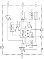
도 2는 본 개시의 특정 예시의 실시예들에 따른, 스타트-업 컨트롤러의 개략적인 블록도이다.
도 3은 종래 기술의 플라이백 컨버터의 개략도이다.
도 4는 본 개시의 또 하나의 특정 예시의 실시예에 따른, 1차측 스타트-업 기술을 포함하는 포워드 파워 컨버터의 개략적인 블록도이다.
본 개시는 다양한 변형들 및 대안의 형태들을 허용하지만, 그의 특정 예시의 실시예들이 도면들에 도시되었고 본 명세서에서 상세히 설명된다. 하지만, 그 특정 예시의 실시예들에 대한 설명은 본 개시를 여기에서 개시된 특정 형태들로 한정하고자 하는 것이 아님을 이해해야 할 것이다.The present disclosure may be more fully understood by reference to the following description taken in conjunction with the accompanying drawings.
1 is a schematic block diagram of a flyback power converter including a primary side start-up technique, in accordance with an embodiment of a specific example of the present disclosure;
Figure 2 is a schematic block diagram of a start-up controller, in accordance with embodiments of certain illustrative aspects of the present disclosure.
3 is a schematic diagram of a prior art flyback converter.
4 is a schematic block diagram of a forward power converter including a primary side start-up technique, in accordance with another specific example embodiment of the present disclosure;
While the present disclosure permits various modifications and alternative forms, embodiments of specific examples thereof are shown in the drawings and are described in detail herein. However, it should be understood that the description of embodiments of that particular example is not intended to limit the present disclosure to the specific forms disclosed herein.
전원 공급 장치, 특히 DC-DC 및 AC-DC 파워 컨버터들은 전형적으로 그것들을 스타트 업하기 위한 고유 회로망을 갖는다. 본 개시의 다양한 실시예들에 따르면, 파워 컨버터는 스타트-업 컨트롤러 및 2차측 컨트롤러를 포함할 수 있으며, 여기서 스타트-업 컨트롤러는 전력(전압)이 파워 컨버터의 1차측에 처음 인가될 때 2차측 컨트롤러에 전력을 전송하는데 이용된다. 이것은 2차측 컨트롤러의 자원들을 복제하지 않고 1차측의 개별 구성요소들을 최소화하는, 1차측에 종래의 디바이스들을 사용하여 파워 컨버터의 스타트-업하기 위한 저비용 집적 회로(IC) 해결책을 제공한다.Power supplies, especially DC-DC and AC-DC power converters, typically have a proprietary network for starting them up. According to various embodiments of the present disclosure, the power converter may include a start-up controller and a secondary-side controller, wherein the start-up controller is configured such that when power (voltage) is first applied to the primary side of the power converter, It is used to transfer power to the controller. This provides a low cost integrated circuit (IC) solution for starting up the power converter using conventional devices on the primary side, minimizing the individual components of the primary without duplicating the resources of the secondary controller.
스타트-업 컨트롤러는 파워 컨버터를 스타트-업하도록 특별히 설계되고, 여기서 스타트-업 컨트롤러는 파워 컨버터의 1차측에 위치하며 2차측 컨트롤러는 파워 컨버터(변압기)의 전기적으로 절연된 2차측에 위치한다. 스타트-업 컨트롤러는 두 가지 동작 모드를 가질 수 있다: 1) 스타트-업 컨트롤러는 개루프 전류 레귤레이터로서 동작하고, 2) 스타트-업 컨트롤러는 파워 스위치를 제어하기 위해 2차측 컨트롤러로부터 외부 PWM 명령들을 수신한다. 개루프 전류 레귤레이터 모드에서, 스타트 업 컨트롤러에는 초기에 DC 소스 전압, 예컨대 배터리 또는 정류된 AC 라인으로부터 직접 전력이 공급된다. DC 또는 정류된 AC 라인 전압을 변압기에 결합시키는 파워 스위치의 ON 시간 동안, 변압기의 1차 권선의 전류는 스타트-업 컨트롤러가 모니터링하는 최대 전류 레벨까지 상승할 수 있다. 파워 스위치의 OFF 시간은 파워 컨버터가 그의 정격 전력 용량의 작은 부분만을 출력하도록 외부 커패시터에 의해 설정된다. 정격 출력 전력의 이 작은 부분은 파워 컨버터의 출력 커패시터를 충전하고 2차측 컨트롤러에 전력을 공급한다. 이 시간 동안 파워 컨버터의 부하가 끊어질 수 있다.The start-up controller is specifically designed to start-up the power converter, where the start-up controller is located on the primary side of the power converter and the secondary controller is located on the electrically isolated secondary side of the power converter (transformer). The start-up controller can have two modes of operation: 1) the start-up controller acts as an open-loop current regulator; and 2) the start-up controller receives external PWM commands from the secondary controller to control the power switch . In open-loop current regulator mode, the startup controller is initially powered directly from a DC source voltage, such as a battery or a rectified AC line. During the ON time of the power switch that connects the DC or rectified AC line voltage to the transformer, the current in the primary winding of the transformer can rise to the maximum current level monitored by the start-up controller. The OFF time of the power switch is set by the external capacitor so that the power converter outputs only a small fraction of its rated power capacity. This small fraction of the rated output power charges the output capacitor of the power converter and supplies power to the secondary controller. During this time, the load on the power converter may be cut off.
파워 컨버터의 출력이 충분한 전압 레벨로 충전될 때에는 2차측 컨트롤러가 활성화되어 스타트-업 컨트롤러로부터 파워 스위치를 제어할 것이다. 파워 컨버터가 파워 업(power up)됨에 따라, 스타트-업 컨트롤러는 변압기의 1차측 3차 권선으로부터 바이어스를 수신할 수 있다. 출력 전력은 단지 파워 컨버터의 정격 전력의 작은 부분이기 때문에, 출력 전압은 2차측 컨트롤러가 작동할 수 없는 경우에 전력 제너 다이오드와 같은 간단한 전압 분로(shunt) 기술에 의해 쉽게 과전압으로부터 보호될 수 있다.When the output of the power converter is charged to a sufficient voltage level, the secondary controller will be activated to control the power switch from the start-up controller. As the power converter is powered up, the start-up controller can receive a bias from the primary side tertiary winding of the transformer. Because the output power is only a small fraction of the rated power of the power converter, the output voltage can easily be protected from overvoltage by a simple voltage shunt technique such as a power zener diode when the secondary controller can not operate.
스타트-업 컨트롤러가 2차측 컨트롤러로부터 외부 PWM 명령들(신호들)을 수신하면, 2차측 컨트롤러로부터의 외부 PWM 명령들이 검출될 때 스타트-업 컨트롤러는 외부 PWM 명령 모드로 전환된다. 파워 스위치의 ON 및 OFF 시간은 2차측 컨트롤러에 의해 결정되므로, 파워 컨버터는 그의 정격 전력 또는 출력 전압을 조절하는데 필요한 전력을 부하에 전달할 수 있다. 정상 동작시 2차측 컨트롤러는 파워 컨버터로부터 부하로의 출력 전압을 조절한다. 2차측 컨트롤러는 (스위치와 스위칭 포스트 레귤레이터 중 어느 하나를 통해) 부하를 파워 컨버터에 연결할 수 있다.When the start-up controller receives external PWM commands (signals) from the secondary controller, the start-up controller switches to the external PWM command mode when external PWM commands from the secondary controller are detected. Since the ON and OFF times of the power switch are determined by the secondary controller, the power converter can deliver the power required to regulate its rated power or output voltage to the load. In normal operation, the secondary controller regulates the output voltage from the power converter to the load. The secondary controller (via either the switch or the switching post regulator) can connect the load to the power converter.
2차측 컨트롤러로부터의 PWM 명령들은 분리 회로, 예를 들어 옵토커플러 또는 펄스 변압기를 통해 스타트-업 컨트롤러로 전송된다. 분리 회로는 선형적으로 동작할 필요가 없고, 따라서 선형 제어가 사용된다면 옵토커플러의 전류 전달 비(CTR) 문제들에 의해 야기된 문제들을 완화할 수 있다. 2차측 컨트롤러는, 파워 컨버터가 전력을 공급하고 있는 부하(애플리케이션)에 위치한 마이크로프로세서 자원들을 이용할 수 있어 정교한 파워 컨버터 제어 기술이 사용될 수 있다.PWM commands from the secondary controller are sent to the start-up controller through a separate circuit, for example an optocoupler or a pulse transformer. The isolation circuit does not need to operate linearly and thus can alleviate the problems caused by the current transfer ratio (CTR) problems of the optocoupler if linear control is used. The secondary controller can utilize microprocessor resources located in the load (application) to which the power converter is supplying power, so sophisticated power converter control techniques can be used.
스타트-업 컨트롤러가 외부 PWM 명령 수신을 중단하면, 스타트-업 컨트롤러는 그의 개방 루프 전류 레귤레이터 모드로 되돌아갈 것이다. 어느 모드에서든 스타트-업 컨트롤러는 저전압 및 과전압으로부터 파워 스위치 드라이버를 보호한다. 스타트-업 컨트롤러는 최대 허용 변압기 1차 전류를 제한한다. 스타트-업 컨트롤러는 플라이백 파워 컨버터와 포워드 파워 컨버터 중 어느 하나를 스타트-업하는데 사용될 수 있다. 플라이백 파워 컨버터 애플리케이션에 사용될 때 스타트-업 컨트롤러는 예를 들면, 플라이백 파워 컨버터가 동작의 연속 전도 모드로 너무 깊숙이 들어가는 것을 방지하는 추가 전류-감지 비교기(그러나 이에 한정되지는 않음)와 같은 일부 추가 특징부를 구비하고, 이로써 플라이백 파워 컨버터의 출력을 과전류 오류 상태로부터 보호한다.If the start-up controller stops receiving external PWM commands, the start-up controller will go back to its open-loop current regulator mode. In either mode, the start-up controller protects the power switch driver from undervoltage and overvoltage. The start-up controller limits the maximum permissible transformer primary current. The start-up controller can be used to start-up either the flyback power converter or the forward power converter. The start-up controller, when used in a flyback power converter application, may include, for example, an additional current-sense comparator, such as but not limited to an additional current-sense comparator that prevents the flyback power converter from entering too deep into the continuous conduction mode of operation And further features to thereby protect the output of the flyback power converter from an overcurrent fault condition.
스타트-업 컨트롤러를 바이어스하는 데 사용되는 변압기의 1차측 3차 권선의 전압은 플라이백 컨버터의 출력 전압에 결합될 수 있다. 따라서 3차 권선의 전압은, 2차측 컨트롤러가 제대로 동작할 수 없는 경우 스타트-업 컨트롤러의 과전압 록아웃(over-voltage lockout; OVLO) 회로에 의해 과전압 보호의 추가 레벨로서 사용될 수 있는 출력 전압 피드백 메커니즘으로서 사용될 수 있다.The voltage of the primary winding of the primary of the transformer used to bias the start-up controller may be coupled to the output voltage of the flyback converter. The voltage on the tertiary winding is therefore an output voltage feedback mechanism that can be used as an additional level of overvoltage protection by the overvoltage lockout (OVLO) circuit of the start-up controller if the secondary controller can not operate properly. Lt; / RTI >
포워드 컨버터 애플리케이션에 사용될 때 포워드 컨버터 설계는 다음을 필요로 할 수 있다: 변압기의 1차측 3차 권선의 출력부와 스타트-업 컨트롤러의 바이어스 입력부 사이에 선형 레귤레이터가 필요할 수 있다. 이것은 3차 권선이 정류된 AC 전압에 결합되고 컨버터의 출력 전압에는 결합되지 않기 때문이다. 포워드 컨버터의 변압기의 리셋 권선은 파워 컨버터의 2차측에 위치하며, 변압기 리셋을 제공하기 위해 능동적으로 클램핑된다. 또한, 능동 클램프는 2차측 컨트롤러에 대한 바이어스의 메인 소스가 포워드 컨버터의 출력 필터 인덕터의 3차 권선으로부터 설정될 때까지 2차측 컨트롤러에 초기 바이어스를 제공하도록 설계될 수 있다.When used in a forward converter application, the forward converter design may require: a linear regulator may be required between the output of the primary winding of the transformer primary and the bias input of the start-up controller. This is because the tertiary winding is coupled to the rectified AC voltage and is not coupled to the output voltage of the converter. The reset winding of the transformer of the forward converter is located on the secondary side of the power converter and is actively clamped to provide a transformer reset. The active clamp may also be designed to provide an initial bias to the secondary controller until the main source of the bias for the secondary controller is set from the tertiary winding of the output filter inductor of the forward converter.
이제 도면들을 보면, 예시적인 실시예들의 세부 사항들이 개략적으로 도시되어 있다. 도면들에서 같은 요소들은 같은 숫자들로 나타내어지며, 유사한 요소들은 같은 숫자들에 다른 소문자 첨자를 붙여서 나타내어질 것이다.Turning now to the drawings, details of exemplary embodiments are schematically illustrated. In the drawings, like elements are denoted by like numerals, and like elements are denoted by the same numerals with different lowercase subscripts.
이제 도 1을 보면, 본 개시의 특정 예시의 실시예에 따른, 1차측 스타트-업 기술을 포함하는 플라이백 파워 컨버터의 개략적인 블록도가 도시되어 있다. 개괄적으로 숫자 100으로 표시된 플라이백 파워 컨버터는 AC 라인 전원(102)에 결합된 1차측 파워 정류기 및 필터들(104), 스타트-업 컨트롤러(106), 커패시터(107), 변압기(122), MOSFET 스위치(116), 전류 감지 저항기(124), 바이어스 전압 정류기(114), 파워 정류기(135), 제너 다이오드(130), 2차측 컨트롤러(118), 스위칭 포스트 레귤레이터(120), 및 분리 회로(108)를 포함할 수 있다. 플라이백 파워 컨버터(100)는 스타트-업 후에 조정된 전압을 애플리케이션 부하(128)에 제공한다. AC 라인 전원(102)은 약 47Hz 내지 약 63Hz의 주파수에서 약 85 내지 265 볼트의 교류 (AC)의 범용 범위에 있을 수 있다. 여기에 개시된 실시예들은 다른 전압들과 주파수들에 적용될 수 있음이 예상되고 본 개시의 범위 내에 있다. AC 소스에 결합된 1차측 파워 정류기 및 필터들(104)을 사용하는 대신에 DC 소스가 사용될 수 있다.Turning now to Fig. 1, there is shown a schematic block diagram of a flyback power converter including a primary side start-up technique, in accordance with an exemplary embodiment of the present disclosure. The flyback power converter, generally indicated by numeral 100, includes a primary side power rectifier and filters 104 coupled to an AC
AC 라인 파워(102)가 1차측 파워 정류기 및 필터들(104)에 인가될 때, 그 결과 DC 전압(V_Link)이 발생한다. 이 DC 전압(V_Link)은 변압기(122)의 1차 및 스타트-업 컨트롤러(106)의 VIN 입력부에 결합된다. 스타트-업 컨트롤러(106)는 전압(V_Link)이 그것의 적절한 동작을 위한 충분한 전압에 도달할 때 활성화된다. 일단 활성화되면, 스타트-업 컨트롤러(106)는 자신의 게이트 노드(출력 핀)로부터 MOSFET 스위치(116)를 구동하기 시작한다. 스타트-업 컨트롤러(106)는 MOSFET 스위치(116)를 관통하는 피크 전류의 조절에 기초하여 개방 루프 방식으로 MOSFET 스위치(116)의 스위칭을 제어한다. MOSFET 스위치(116) 및 MOSFET 스위치(116)를 관통하는 피크 전류에 비례하는 변압기(122)의 1차측과 직렬로 연결된 저항기(124)를 가로질러 전압이 발생한다. 이런 전압은, 피크 전류를 소정 설계 값으로 제한하기 위해 전류를 감지하여 MOSFET 스위치(116)의 온 시간을 조정하는 스타트-업 컨트롤러(106)의 C/S(전류 감지) 입력부에 결합된다. 스타트-업 컨트롤러(106)의 내부 선형 레귤레이터(도 2의 레귤레이터(230) 참조)(그것의 입력은 DC 전압(V_Link)임)는 스타트-업 컨버터(106)의 내부 회로들에 의해 사용 가능한 전압(VDD)을 조절한다. VDD는 스타트-업 컨트롤러(106)의 게이트 노드에서의 피크 전압이다. 초기에, 내부 선형 레귤레이터는 스타트-업 컨트롤러(106)의 동작을 위해 VDD를 공급하지만, 일단 DC 전압이 파워 다이오드(114)를 통해 변압기(122)의 1차측 3차 권선으로부터 제공되면, 이 내부 선형 레귤레이터는 스타트-업 컨트롤러(106)의 내부 회로들에 전류를 공급하는 것을 중단한다. 이로 인해 스타트-업 컨트롤러(106)의 내부 열 발산이 감소될 수 있다.When
MOSFET 스위치(116)를 온 및 오프로 구동하면, 정류기(135)를 통과하는 변압기(122)는 커패시터(126)를 전압(V_Bulk)으로 충전시킬 것이다. 스위칭 포스트 레귤레이터(120)는 오프 상태이므로, 이로부터 출력 전압(V_Out)은 존재하지 않는다. 따라서, 애플리케이션 부하(128)는 변압기(122)의 출력으로부터 분리된다. 전압(V_Bulk)이 증가함에 따라, 2차측 컨트롤러(118)는 활성화된다. 2차측 컨트롤러(118)의 V/S 입력부의 전압(V_Bulk)이 원하는 값에 도달할 때에는, 2차측 컨트롤러(118)가 분리 회로(108)를 통해 펄스 폭 변조(PWM) 명령들을 스타트-업 컨트롤러(106)의 PWM 입력부에 송신함으로써 스타트-업 컨트롤러(106)부터의 게이트 출력을 제어하기 시작할 것이다. 이제 2차측 컨트롤러(118)는 MOSFET 스위치(116)를 제어한다.Driving the
또한, 변압기(122)는 다이오드(114)를 통해 바이어스 전압(V-Bias)을 제공한다. V-Bias는 변압기 커플링에 의해 스타트-업 컨트롤러(106)와 교차-조절될(cross-regulated) 수 있다. 변압기(122)의 권선비는 V_Bias가 스타트-업 컨트롤러(106)의 내부 선형 전압 레귤레이터(230)(도 2)의 출력 전압 설정 포인트보다 높아지도록 함으로써, 이런 내부 선형 전압 레귤레이터(230)를 효과적으로 차단(shutting off)하고 그것의 내부 열 분산을 감소시킨다. 일단 V_Bulk가 그것의 설계 전압까지 상승하면, 2차측 컨트롤러(118)는 스위칭 포스트 레귤레이터(120)를 제어하여 애플리케이션 부하(128)에 V_Out을 제공함으로써, 플라이백 컨버터(100)에 전력을 공급(power loading)할 것이다.
이제 도 2를 보면, 본 개시의 특정 예시의 실시예들에 따른, 스타트-업 컨트롤러의 개략적인 블록도가 도시되어 있다. 스타트-업 컨트롤러(106)는 고전압 레귤레이터(230), 내부 바이어스 전압 회로들(232), 제 1 전압 비교기(234), 제 2 전압 비교기(238), 고정 블랭킹 시간 회로(240), 내부 전류 레귤레이터 및 로직 회로들(236), 외부 게이트 명령 검출 회로(242), 신호 버퍼(244), 로직 회로들(236)에 의해 제어되는 스위치(246), MOSFET 드라이버(248), 고정 오프-시간 타이머(250), 및 과전압 및 저전압 록아웃 회로들(252)을 포함할 수 있다.Turning now to Fig. 2, a schematic block diagram of a start-up controller is shown, in accordance with certain exemplary embodiments of the present disclosure. The start-up
VIN 입력부는 브리지 정류기 및 필터들(104)(도 1)로부터 제공된 전압에 결합되고, AC 라인 전압(102)에 의존하는 고전압 레귤레이터(230)의 입력 전압으로서 사용된다. 고전압 레귤레이터(230)는 MOSFET 드라이버(248) 및 다른 내부 바이어스 전압들(바이어스 회로들(232))에 전력을 공급하기 위해 더 낮은 전압(VDD)을 제공하는 선형 레귤레이터일 수 있다. VDD는 또한 내부 고전압 레귤레이터(230)가 턴 오프될 수 있도록 외부 소스(예를 들어, 변압기(122)(도 1)로부터의 V_Bias)로부터 제공될 수 있고, 이로써 스타트-업 컨트롤러(106) 내의 내부 전력 소실을 모면한다. 전압(VDD)은 스타트-업 컨트롤러(106) 내의 회로들을 설계 사양 전압들로부터 보호하기 위해 과전압 및 저전압 록아웃 회로들(252)에 의해 모니터링될 수 있다. 내부 바이어스 및 전압 기준부들은 고전압 레귤레이터(230) 또는 VDD에 대한 외부 소스, 예컨대 변압기(122)로부터 그것의 입력 동작 전압을 수신할 수 있는 내부 바이어스 전압 회로들(232)에 의해 제공될 수 있다.The V IN input is coupled to the voltage provided from the bridge rectifier and filters 104 (FIG. 1) and used as the input voltage of the
게이트 드라이버(248)로의 게이트 드라이브 명령들은 로직 회로들(236)에 의해 제어될 수 있는 스위치(246)를 사용하여 2개의 소스들 사이에 스위칭될 수 있다. 제 1 소스는 내부 전류 레귤레이터 및 로직 회로들(236)일 수 있고, 제 2 소스는 PWM 입력부에 결합되고 신호 버퍼(244)에 의해 내부에서 버퍼링된 외부 소스일 수 있다.Gate drive instructions to
MOSFET 스위치(116)를 통해 흐르는 전류는 스타트-업 컨트롤러(106)의 전류 감지(C/S) 입력부에 결합될 수 있는 저항기(124) 양단에 발생된 유사(analogous) 전압에 의해 모니터링될 수 있다. MOSFET 전류는 변압기의 1차 전류와 동일할 수 있다. 게이트 드라이버(248)가 MOSFET 스위치를 구동하기 시작할 때에는, 로직 회로(236)는 고정 블랭킹 시간 회로(240)를 시동하고, 그리고 나서 고정 블랭킹 시간 회로(240)는 내부 전류 레귤레이터 및 로직 회로(236)에 도달하지 않도록 전류 감지(C/S) 노드에서의 신호를 잠시 블랭킹시켜서 그 안에 있는 내부 전류 레귤레이터가 MOSFET 스위치(116)를 관통하는 초기 턴-온 전류 스파이크를 무시할 수 있게 한다. 제 1 비교기(234) 및 제 2 비교기(238)는 전류 감지(C/S) 입력부의 전압을 모니터링한다. 제 1 비교기(234)는 고정 블랭킹 시간 회로(240)의 블랭킹 시간 주기가 종료된 후 짧은 시간 간격 동안 C/S 노드의 전압을 모니터링한다. 이 짧은 시간 간격 동안 C/S 노드의 전압이 제 1 전압 기준값(VREF1)을 초과하면, 게이트 드라이브가 종료된다. 제 2 비교기(238)는 전류 감지(C/S) 입력에서 허용되는 최대 전압(MOSFET 스위치(116)를 관통하는 전류)을 설정한다. 전류 감지(C/S) 입력부의 전압이 제 2 전압 기준값(VREF2)보다 크면, 게이트 드라이브도 또한 종료된다. 게이트 드라이브가 종료될 때, 게이트 드라이브는 고정 오프-시간 회로(250)에 의해 결정된 시간 주기 동안 오프 상태로 유지된다. 이런 오프 시간 주기는 스타트-업 컨트롤러(106)의 TOFF 노드에 있는 커패시터(107)의 커패시턴스 값에 의해 외부에서 선택될 수 있다.The current flowing through the
외부 신호가 펄스 폭 변조(PWM) 입력 노드에 인가될 때에는, 외부 신호는 외부 게이트 명령 검출 회로(242)에 의해 검출될 수 있다. 외부 PWM 신호가 이렇게 검출될 때에는, 로직 회로들(236) 내의 로직은 MOSFET 드라이버(248)를 구동하기 위해 스위치(246)를 이 외부 PWM 신호에 결합시킴으로써, 파워 MOSFET 스위치(116)를 스타트-업 컨트롤러(106) 외부의 PWM 소스로부터 제어한다. PWM 신호 주파수는 예를 들어 약 20kHz 내지 약 65kHz일 수 있지만, 이것에 한정되는 것은 아니다. PWM 입력 노드의 PWM 신호가 소정 수보다 많은 스위칭 주기들 동안, 예를 들어 20kHz(250 마이크로 초)에서 5 스위칭 주기들 동안 스위칭을 중단하면(예컨대, 하이 상태와 로우 상태 중 어느 하나로 유지되면), 로직 회로들(236) 내의 로직은 스위치(246)가 로직 회로들(236)의 PWM 출력으로 다시 스위칭되게 하고, 이로써 MOSFET 드라이버(248)는 로직 회로들(236)의 PWM 출력으로부터 구동된다. 접지 노드(Gnd)는 스타트-업 컨트롤러(106) 내의 회로들에 대한 회로 접지 또는 공통 포인트이다. 이 접지 노드는 외부 MOSFET 스위치(116)로의 PWM 구동 전류와 VIN 및 VDD 노드들에서의 전압들의 바이어스 리턴 전류들 둘 다에 대한 복귀 지점을 제공할 수 있다.When an external signal is applied to the pulse width modulation (PWM) input node, the external signal can be detected by the external gate
도 1을 다시 보면, 스타트-업 컨트롤러(106)는 변압기 커플링을 통해 플라이백 파워 컨버터의 출력을 선형적으로 조정할 수 있는 1차측 전원 공급 컨트롤러가 아니다. 스타트-업 컨트롤러(106)는 2차측 컨트롤러(118)의 정밀 기준부 및 전압 에러 증폭기를 복제하지 않는다. 스타트-업 컨트롤러(106)는 기본적으로 2개의 동작 모드를 갖는다: 제 1 모드에서, 플라이백 파워 컨버터(100)의 스타트-업 동안, 스타트-업 컨트롤러(106)는 2차측 컨트롤러(118)가 MOSFET 스위치(116)를 구동하는 PWM 신호들의 제어(명령)를 획득할 때까지 MOSFET 스위치(116)를 구동하는 개방 루프 전류 레귤레이터로서 동작한다. 제 2 모드에서, 일단 2차측 컨트롤러(118)가 완전히 동작하면, 2차측 컨트롤러(118)는 분리 회로(108)를 통해 스타트-업 컨트롤러(106)에 PWM 신호 명령들을 전송하기 시작한다. (분리 회로(108)를 통한) 2차측 컨트롤러(118)로부터의 외부 PWM 신호 명령들이 스타트-업 컨트롤러(106)에 의해 수신되면, 그것의 내부 게이트 드라이버(248)는 외부 PWM 신호에 결합될 수 있으며, 이로써 2차측 컨트롤러(118)는 이제 MOSFET 스위치(116)를 제어한다.Referring back to Figure 1, the start-up
2차측 컨트롤러(118)는 아날로그 컨트롤러와 디지털 컨트롤러 중 어느 하나(또는 아날로그/디지털 혼성)일 수 있다. 제어 방법들의 출력이 (전형적인) PWM 신호를 제공하는 동안, 매우 정교한 제어 방법들이 2차측 컨트롤러(118)에 의해 사용될 수 있다. 2차측 컨트롤러(118)는 추가적인 제어 정교함을 위해 (스위칭 포스트 레귤레이터(120)를 통해 플라이백 파워 컨버터(100)를 로딩하는) 애플리케이션 부하(128)와 통신할 수 있다.The
본 개시의 교시에 따르면, 2차측 컨트롤러(118)로부터의 PWM 신호 명령들(PWM 펄스들)이 분리 회로(108)(예컨대, 옵토커플러, 펄스 변압기)를 온 또는 오프로 구동하고 어떠한 회로 선형성도 필요로 하지 않기 때문에, 옵토커플러 CTR 문제는 문제가 되지 않는다. 스타트-업 컨트롤러(106)를 포함하는 개방-루프 전류 레귤레이터는 변압기(122)의 2차 권선에 소량의 스타트-업 전력을 제공하는 매우 불연속적인 동작 모드로 플라이백 파워 컨버터(100)를 동작시키도록 설계되고, 이로써 출력 커패시터(126)는 충전되고 2차측 컨트롤러(118)에 동작 전압을 공급한다.According to the teachings of the present disclosure, the PWM signal commands (PWM pulses) from the
(외부 MOSFET 스위치(116)를 온으로 구동하는) ON 시간은 전형적으로 스타트-업 컨트롤러(106)의 C/S 노드의 PWM 신호가 0 볼트로부터 제 2 비교기(238)의 VREF2 전압으로 램프하는데 걸리는 시간의 양에 의해 결정된다. (외부 MOSFET 스위치(116)를 오프로 구동하는) OFF 시간은 고정 시간-오프 타이머(250)에 의해 결정될 수 있다. 고정 시간-오프 타이머(250)의 지속 시간은 스타트-업 컨트롤러(106)의 TOFF 노드에 결합된 커패시터(107)의 값에 의해 결정될 수 있다. 예를 들면, 개방 루프 전류 레귤레이터 기술 및 TOFF 노드에 결합된 커패시터(107)에 의해 설정된 충분히 긴 OFF 시간을 사용하여 대략 1 와트의 출력 전력을 전달하도록, 20 와트의 전력으로 정격된 플라이백 컨버터가 만들어질 수 있다.The ON time (which drives the
외부 PWM 신호가 스타트-업 컨트롤러(106)의 PWM 노드에 인가되고 외부 게이트 명령 검출 회로(242)에 의해 검출될 때에는, 스위치(246)는 게이트 드라이버(248)로의 입력을 내부 전류 레귤레이터 및 로직 회로(236)로부터 외부 소스로 (신호 버퍼(244)를 통한 PWM 노드로부터) 변경한다. 이로 인해, 2차측 컨트롤러(118)는 정격 출력 전력 및 출력 전압 조정을 달성하기 위해 적절한 주파수 및 PWM 듀티 사이클에서 플라이백 컨버터(112)를 구동할 수 있다. 이런 모드에서, 스타트-업 컨트롤러(106)는 단순히 1차측 바이어스된 게이트 드라이버이다. 그러나, 스타트-업 컨트롤러(106)는 여전히 제 1 및 제 2 전압 비교기들(234, 238)에 의해 수여되는(afforded) 전류 보호를 제공한다. 제 1 및 제 2 전압 비교기들(234 또는 238) 중 어느 하나가 트립(trip)하면(출력 상태를 변경하면), 스위치(246)는 OFF 시간이 고정 시간-오프 타이머(250)에 의해 설정되는 내부 전류 레귤레이터 및 로직 회로(236)로부터 그의 명령들을 얻는 위치로 다시 변경될 것이다. 여기서 스위치(246)는 고정 오프-시간 타이머(250)에 의해 설정된 시간 주기의 끝까지 신호 버퍼(244)를 통해 명령들을 수신하는 것으로 다시 위치를 변경할 수 없다. 분리 회로(108)를 통한 2차측 컨트롤러(118)로부터의 외부 PWM 신호가 250μs를 초과하는 시간 주기 동안 중단될 때(하이 상태와 로우 상태 중 어느 하나로 유지됨) (외부 게이트 명령 검출 회로(242)에 의해 더 이상 검출되지 않음), 스위치(246)는 내부 전류 레귤레이터 및 로직 회로(236)로부터 그의 명령들을 얻는 위치로 다시 변경될 것이다.When external PWM signal is applied to the PWM node of the start-up
과전압 및 저전압 록아웃 회로들(252)은 게이트 노드에서의 피크 전압이 플라이백 컨버터(112)의 외부 전력 MOSFET 스위치(116)에 대해 적절한 범위 내에 있음을 보장한다. 저전압 록아웃(UVLO) 회로는 MOSFET(116)의 게이트를 적절하게 향상시키는데 충분한 전압이 사용될 수 있음을 보장한다. 과전압 록아웃(OVLO) 회로는 전압이 파워 MOSFET(116)의 전형적인 게이트 전압 정격을 초과하지 않음을 보장한다. OVLO 회로(252)는 또한 또 하나의 중요한 기능을 제공한다: 그것은 2차측 컨트롤러(118)가 스타트-업 및 조정을 실패하는 것으로부터 보호되어야 한다. 2차측 컨트롤러(118)가 명령을 획득하지 않으면, 스타트-업 컨트롤러(106)는 과전압 임계값에 도달할 때까지 출력 커패시터(126)를 계속 충전할 것이다. 출력 커패시터(126) 상의 이 전압은 변압기(122) 권선 커플링을 통해 스타트-업 컨트롤러(106)의 VDD 노드로 다시 반향되어 스타트-업 컨트롤러(106)의 OVLO 회로를 트립할 것이다. 회로(252)의 OVLO 부분의 고전압 한계가 초과될 때에는, MOSFET 드라이버(248) 출력은 금지될 것이다. OVLO 회로(252)는 예를 들면 2 볼트의 히스테리시스 밴드를 가질 수 있지만, 이것에 한정되는 것은 아니다. 따라서, MOSFET 스위치(116)의 게이팅은 스타트-업 컨트롤러(106)의 VDD 노드의 전압이 OVLO 회로(252)의 히스테리시스 대역의 하한 아래로 떨어질 때까지 정지된다. (2차측 컨트롤러(118)가 고장 나는 경우) 추가 레이어의 과전압 보호를 위해, 파워 제너 다이오드(130)(또는 일부 다른 형태의 능동형 션트 레귤레이터)가 변압기(122)의 출력 양단에(예컨대, 커패시터(126) 양단에) 배치될 수 있다. 플라이백 파워 컨버터(100)의 출력 전력은 스타트-업 컨트롤러(106)의 TOFF 노드 상의 커패시터(107)로 긴 OFF 시간을 선택함으로써 낮게 설정될 수 있기 때문에, 정류기(135)를 통과하는 변압기(122)의 출력은 그것으로부터 DC 출력을 가로질러 션트된 파워 제너 다이오드(130)를 사용함으로써 과전압으로부터 합리적으로 보호될 수 있다.The overvoltage and
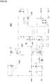
이제 도 4를 보면, 본 개시의 또 하나의 특정 예시의 실시예에 따른, 1차측 스타트-업 기술을 포함하는 포워드 파워 컨버터의 개략적인 블록도가 도시되어 있다. 개괄적으로 숫자 400으로 표시된 포워드 파워 컨버터는 AC 라인 전원(402)에 결합된 1차측 파워 정류기 및 필터(404), 스타트-업 컨트롤러(106), 커패시터(107), 레귤레이터(430), MOSFET 스위치(416), 전류 감지용 저항기(424), 바이어스 전압 정류기(414), 변압기(422), 2차측 컨트롤러(418), 파워 정류기들(435 및 436), 능동 클램프 회로(440), 전류 감지 변압기(445), 인덕터(450), 다이오드(455), 클램프 제너 다이오드(465), 스위치(460), 분리 회로(408), 및 애플리케이션 부하(428)를 포함할 수 있다. AC 소스에 결합된 1차측 파워 정류기 및 필터들(404)을 사용하는 대신에 DC 소스가 사용될 수 있다.Turning now to FIG. 4, a schematic block diagram of a forward power converter including a primary-side start-up technique is shown, in accordance with another specific example embodiment of the present disclosure. The forward power converter, generally designated
변압기(422)는 4개의 권선들, 즉 1) V_Link에 결합된 1차 권선, 2) 파워 정류기들(435 및 436)에 결합된 2차 권선, 3) 능동 클램프 회로(440)에 결합된 리셋 권선, 및 4) 정류기(414)에 결합된 3차 권선을 포함할 수 있다. AC 라인(402)은 약 47Hz 내지 약 63Hz의 주파수에서 약 85 내지 265 볼트 교류(AC)의 범용 범위에 있을 수 있다. 여기에 개시된 실시예들은 다른 전압들과 주파수들에 적용될 수 있음이 예상되고 본 개시의 범위 내에 있다. AC 라인 전원(102)이 1차측 파워 정류기 및 필터들(404)에 인가될 때, 그 결과 DC 전압(V_Link)이 발생한다. 이 DC 전압(V_Link)은 변압기(422)의 1차 권선 및 스타트-업 컨트롤러(106)의 VIN 입력부에 결합된다. 스타트-업 컨트롤러(106)는 AC 라인 전원(402)의 인가시에 (그것의 VIN 노드를 통해) V_Link에 의해 초기에 바이어스된다. 스타트-업 컨트롤러(106)는 전압(V_Link)이 그것의 적절한 동작을 위한 충분한 전압에 도달할 때 활성화된다. 일단 이렇게 바이어스되면, 스타트-업 컨트롤러(106)는 MOSFET 스위치(416)를 온 및 오프로 게이팅한다. 스타트-업 컨트롤러(106)는 자신의 C/S 노드에 결합된 전류 감지 저항기(424) 양단에 발생된 전압을 모니터링함으로써 변압기(422)의 1차 권선을 관통하는 전류의 개방 루프 조정을 제공한다.
MOSFET 스위치(416)가 게이트 온될 때에는, 변압기(422) 권선들의 도트 측들(페이징)이 양으로 되어 전류가 1차 권선, 2차 권선 및 3차 권선을 통해 흐를 수 있게 한다. 전류는 정류기(414) 및 전압 레귤레이터(430)를 통해 흘러서 스타트-업 컨트롤러(106)의 VDD 포트에 바이어스를 제공한다. 전류는 또한 정류기(435), 전류 감지 변압기(445), 인덕터(450)의 메인 권선을 통해 흐르고 커패시터(426)를 충전한다. 이 때, 스위치(460)가 개방되어 있기 때문에 애플리케이션 부하(428)는 분리되어 있다. MOSFET(416) 스위치가 게이트 오프될 때에는, 전류가 리셋 권선을 통해 능동 클램프 회로(440)로 흐른다. 능동 클램프 회로(440)는 자신의 PNP 트랜지스터의 게이트 상의 제너 다이오드에 의해 리셋 권선 전압을 클램핑한다. PNP 트랜지스터의 컬렉터 상의 제너 다이오드는 전압(VCCS)을 클램핑한다. VCCS는 2차측 컨트롤러(418)용 바이어스 전압이다. 변압기(422)의 리셋으로부터의 자화(magnetization) 에너지는 2차측 컨트롤러(418)를 바이어싱하는 것을 돕기 위해 사용될 수 있다. MOSFET 스위치(416)가 게이트 오프될 때에는 전류가 다이오드(455)에 결합된 인덕터(450)의 3차 권선을 통해 흐른다. 이것은 또한 에너지가 전압(VCCS)을 제공하도록 흐르게 한다. 포워드 파워 컨버터(400)가 동작하면, 다이오드(455)를 통해 전압(VCCS)으로 흐르는 전류는 2차측 컨트롤러(418) 동작용 주전원이 될 것이다.When the
VCCS가 충분한 전압에 도달할 때, 2차측 컨트롤러(418)는 분리 회로(408)를 통해 스타트-업 컨트롤러(106)에 게이팅 명령들을 송신할 수 있다. 이제 MOSFET 스위치(416)의 게이팅은 2차측 컨트롤러(418)에 의해 제어된다. 2차측 컨트롤러(418)는 이후 전압(V_OUT)을 조절하고, 스위치(460)를 닫고, 그리고 애플리케이션 부하(428)에 전력을 인가할 수 있다.When V CCS reaches a sufficient voltage, the
플라이백 파워 컨버터(100) 또는 포워드 파워 컨버터(400)를 시동시키기 위해 스타트-업 컨트롤러(106)를 사용할 때 몇 가지 중요한 차이점이 있다. 예를 들어, 변압기(422)의 3차 권선의 전압은 포워드 컨버터(400)의 출력 전압에 결합하지 않는다. 대신에 그것은 V_Link에 결합된다. 따라서 변압기 커플링을 통해서는 어떠한 2차 전압 정보도 사용될 수 없다. 그것이 전압 레귤레이터(430)가 스타트-업 컨트롤러(106)의 VDD 포트 상의 전압을 조절하는데 필요한 이유이다. 또한, 변압기(422) 3차 권선을 통한 전압 정보의 부족 때문에, 과전압 보호 전략은 2차측 컨트롤러(418)의 고장시에 다르다. 스타트-업 동안 출력부에 전달된 전력은 스타트-업 컨트롤러(106)의 TOFF 노드(포트)에 결합된 선택된 값 커패시터(107)를 이용하여 낮게 설정된다(도 2 참조). 능동 클램프 회로(440)의 PNP 트랜지스터의 컬렉터 상의 제너 다이오드는 VCCS의 전압을 클램프하고 2차측 컨트롤러(418)를 과전압으로부터 보호한다. 포워드 컨버터(400)의 출력부를 가로지른 구성요소들은 제너 다이오드(465)에 의해 보호될 수 있다. 이 제너 다이오드들 둘 다는 보호 션트 레귤레이터들로서 동작한다. 도 2에 도시된 비교기(234)는 포워드 파워 컨버터(400) 설계에 필요하지 않다. 그것의 목적은 플라이백 파워 컨버터(100)가 동작의 연속 전도 모드에 진입하는 것을 방지하는 것이다. 그러나, 포워드 파워 컨버터(400)의 인덕터(450)의 메인 권선은 전형적으로 연속 전도 모드로 유지된다.There are several important differences when using the start-up
파워 제너 다이오드(130/465)는 커패시터(126/426)와 병렬로 배치될 수 있으며, 여기서 제너 다이오드(130/465)의 캐소드는 커패시터(126/426)의 포지티브 측에 결합되고 제너 다이오드(130/465)의 애노드는 커패시터(126/426)의 네거티브 측에 결합될 수 있다. 이러한 구성에서, 제너 다이오드(130/465)는 플라이백 파워 컨버터(100) 또는 포워드 파워 컨버터(400)의 출력을 가로질러 션트된다. 제너 다이오드(130/465) 항복 전압은 커패시터(126/426) 상의 정상 전압 출력보다 높다. 2차측 컨트롤러(118)의 고장이 발생하여 그 결과 과전압이 발생하면, 출력 전압은 제너 다이오드(130/465)가 고장나서(break over) 과전압을 클램핑할 때까지 상승할 것이다. 제너 다이오드(130/465)는 스타트-업 컨트롤러(106)의 TOFF 핀의 커패시터(107)의 커패시턴스 값에 의해 결정되는 플라이백 또는 포워드 파워 컨버터들(100 또는 400)의 출력 전력을 각각 소실시킬 것이다. 제너 다이오드(130/465)는 적어도 해당 전력 소산에 대해 정격이어야 한다. 제너 다이오드(130/465)의 기능이 이러한 션트 클램프 기능을 수행하는 능동 회로망에 의해 대체될 수 있음이 예상되고 본 개시의 범위 내에 있다. 이것은 전형적으로 보다 정확한 항복 전압이 필요한 경우에 수행된다.
기본적으로, 스타트-업 컨트롤러(106)의 목적은, 짧은 ON 시간(MOSFET 스위치(116/416)가 게이트 ON됨) 및 매우 긴 OFF 시간(OFF 시간은 도 2에서 스타트-업 컨트롤러(106)의 T-off 노드에 배치된 커패시터 값에 의해 결정됨)을 갖는 개방 루프-전류 레귤레이터를 구비함으로써 파워 컨버터(100/400)를 시동시키는 것이다. 이러한 방식으로, 약 20와트 내지 60와트 범위의 전력으로 정격된 파워 컨버터(100/400)는 약 1와트의 스타트-업 전력을 가질 수 있다. 따라서, 개방-루프 방식으로, 1와트의 전력이 2차측에 전달되어 컨버터의 출력 커패시터(126/426)를 충전하고 2차측 컨트롤러(118/418)를 시동할 수 있다. 정상적으로 2차측 컨트롤러(118/418)는 출력 커패시터(126/426)가 과충전(과전압)되는 것을 방지하기 위해 제 시간에(in time) 시동될 것이다. 그러나, 2차측 컨트롤러(118/418)가 시동에 실패하면 개방 루프 스타트-업 컨트롤러(106)는 출력 커패시터(126/426)를 계속해서 충전할 것이다(스타트-업 컨트롤러의 개방 루프는 스타트-업 컨트롤러가 어떠한 전압 피드백도 얻지 못함을 의미함). 따라서, 보호를 위해 정상 정격 출력 전압의 약 125% 정도의 전압으로 출력 커패시터(126/426)의 양단 전압을 클램핑하는 것이 필요하다. 이것은 적절한 항복 전압을 갖는 제너 다이오드(130/465)를 사용하여 간단히 수행될 수 있다. 이 제너 다이오드(130/465)는 스타트-업 전력을 처리하도록 정격될 필요가 있다. 예를 들면, 2와트로 정격된 제너 다이오드는 1와트 스타트-업 전력을 쉽게 처리할 것이다. 고장난 2차측 컨트롤러(118/418)를 구비한 파워 컨버터(100/400)는 AC 라인 전원(102/402)이 제거될 때까지 이 제너-클램핑된 상태로 유지될 것이다. 포워드 컨버터(400)의 경우, 이것은 2차측 컨트롤러(418)가 시동에 실패하는 경우 과전압으로부터 보호하는 유일한 방법이다. 플라이백 컨버터(100)에서는, 2차측 컨트롤러(118)의 고장시 과전압을 방지하기 위해 스타트-업 컨트롤러(106)의 OVLO 잠금 회로(252)가 사용될 수도 있다. 이 경우, 제너(130) 클램프는 추가적인 레벨의 보호를 제공한다.Basically, the purpose of the start-up
Claims (39)
제 1 DC 전압을 스타트-업 컨트롤러에 인가하는 단계;
상기 스타트-업 컨트롤러에 의해 파워 스위치를 턴 온 및 오프하는 단계 - 상기 제 1 DC 전압과 상기 파워 스위치는 변압기의 1차 권선에 결합되고, 이로써 상기 변압기의 2차 권선에 AC 전압이 생성됨 -;
2차측 컨트롤러와 부하에 전력을 공급하기 위해 제 2 DC 전압을 제공하도록 제 2 정류기로 상기 변압기의 상기 2차 권선으로부터의 상기 AC 전압을 정류하는 단계; 및
상기 제 2 DC 전압이 원하는 전압 값에 있을 때 상기 스타트-업 컨트롤러로부터 상기 2차측 컨트롤러로 상기 파워 스위치의 제어를 이전하는 단계를 포함하는, 방법.A method for starting up a power converter,
Applying a first DC voltage to the start-up controller;
Turning on and off the power switch by the start-up controller, the first DC voltage and the power switch being coupled to the primary winding of the transformer, whereby an AC voltage is generated in the secondary winding of the transformer;
Rectifying the AC voltage from the secondary winding of the transformer to a second rectifier to provide a second DC voltage to power the secondary controller and the load; And
And transferring control of the power switch from the start-up controller to the secondary controller when the second DC voltage is at a desired voltage value.
상기 스타트-업 컨트롤러는 처음에는 상기 제 1 DC 전압으로부터 이후에는 상기 변압기의 3차 권선으로부터 직접 전력이 공급되는, 방법.The method according to claim 1,
Wherein the start-up controller is initially powered from the first DC voltage and thereafter directly from the tertiary winding of the transformer.
상기 스타트-업 컨트롤러에 의해 상기 파워 스위치를 턴 온 및 오프하는 단계는:
상기 변압기의 상기 1차 권선을 관통하는 최대 전류에 도달할 때까지 상기 파워 스위치를 턴 온하는 단계; 및
이후에 고정 시간 주기 동안 상기 파워 스위치를 턴 오프하는 단계를 포함하는, 방법.3. The method according to claim 1 or 2,
Turning on and off the power switch by the start-up controller comprises:
Turning on the power switch until a maximum current through the primary winding of the transformer is reached; And
And subsequently turning off the power switch for a fixed period of time.
상기 고정 시간 주기는 상기 스타트-업 컨트롤러에 결합된 커패시터의 커패시턴스 값에 의해 결정되는, 방법.The method of claim 3,
Wherein the fixed time period is determined by a capacitance value of a capacitor coupled to the start-up controller.
상기 부하를 상기 제 2 DC 전압에 결합시키도록 요청될 때까지 상기 제 2 DC 전압으로부터 상기 부하를 분리하는 단계를 더 포함하는 방법.5. The method according to any one of claims 1 to 4,
Further comprising isolating the load from the second DC voltage until it is requested to couple the load to the second DC voltage.
상기 부하는 상기 2차측 컨트롤러가 상기 파워 스위치를 제어하기 시작한 이후에 상기 제 2 DC 전압에 결합되는, 방법.6. The method according to any one of claims 1 to 5,
Wherein the load is coupled to the second DC voltage after the secondary controller begins to control the power switch.
상기 제 2 DC 전압에 걸쳐 전압 션트(voltage shunt)를 결합함으로써 상기 제 2 DC 전압의 과전압을 방지하는 단계를 더 포함하는 방법.7. The method according to any one of claims 1 to 6,
Further comprising preventing an overvoltage of the second DC voltage by coupling a voltage shunt across the second DC voltage.
상기 전압 션트는 상기 제 2 DC 전압에 대해 원하는 값보다 높은 항복 전압을 갖는 제너 다이오드인, 방법.8. The method according to any one of claims 1 to 7,
Wherein the voltage shunt is a zener diode having a breakdown voltage higher than a desired value for the second DC voltage.
상기 스타트-업 컨트롤러로부터 상기 2차측 컨트롤러로 상기 파워 스위치의 제어를 이전하는 단계는:
상기 제 2 DC 전압이 상기 원하는 전압 값에 있을 때 상기 2차측 컨트롤러로부터 상기 스타트-업 컨트롤러로 PWM 신호들을 송신하는 단계;
상기 스타트-업 컨트롤러에 의해 상기 2차측 컨트롤러로부터의 상기 PWM 신호들을 검출하는 단계; 및
상기 2차측 컨트롤러로부터 상기 검출된 PWM 신호들로 상기 파워 스위치를 턴 온 및 오프하는 단계를 포함하는, 방법.9. The method according to any one of claims 1 to 8,
Wherein transferring control of the power switch from the start-up controller to the secondary controller comprises:
Transmitting PWM signals from the secondary controller to the start-up controller when the second DC voltage is at the desired voltage value;
Detecting the PWM signals from the secondary controller by the start-up controller; And
And turning the power switch on and off with the detected PWM signals from the secondary controller.
상기 제 2 DC 전압은 상기 스타트-업 컨트롤러가 상기 2차측 컨트롤러로부터 상기 PWM 신호들을 검출한 후에 상기 2차측 컨트롤러에 의해 조정되는, 방법.10. The method according to any one of claims 1 to 9,
Wherein the second DC voltage is adjusted by the secondary controller after the start-up controller detects the PWM signals from the secondary controller.
상기 파워 스위치를 제어하는 단계는:
전력을 보존하기 위해 상기 스타트-업 컨트롤러에 의해 저주파에서 상기 파워 스위치를 턴 온 및 오프하는 단계; 및
상기 2차측 컨트롤러에 의해 고주파에서 상기 파워 스위치를 턴 온 및 오프하는 단계를 더 포함하는, 방법.11. The method according to any one of claims 1 to 10,
Wherein controlling the power switch comprises:
Turning the power switch on and off at a low frequency by the start-up controller to conserve power; And
Further comprising turning the power switch on and off at a high frequency by the secondary controller.
상기 2차측 컨트롤러로부터 상기 스타트-업 컨트롤러로 상기 PWM 신호들을 송신하는 단계는 전압 분리 회로를 통해 PWM 신호들을 송신하는 단계를 더 포함하는, 방법.12. The method according to any one of claims 1 to 11,
Wherein transmitting the PWM signals from the secondary controller to the start-up controller further comprises transmitting PWM signals via a voltage divider circuit.
상기 전압 분리 회로는 광(optical)-커플러인, 방법.13. The method according to any one of claims 1 to 12,
Wherein the voltage isolation circuit is an optical-coupler.
상기 전압 분리 회로는 펄스 변압기인, 방법.14. The method according to any one of claims 1 to 13,
Wherein the voltage separation circuit is a pulse transformer.
상기 AC-DC 파워 컨버터는 AC-DC 플라이백 파워 컨버터를 포함하는, 방법.15. The method according to any one of claims 1 to 14,
Wherein the AC-DC power converter comprises an AC-DC flyback power converter.
상기 AC-DC 파워 컨버터는 AC-DC 포워드 파워 컨버터를 포함하는, 방법.16. The method according to any one of claims 1 to 15,
Wherein the AC-DC power converter comprises an AC-DC forward power converter.
상기 스타트-업 컨트롤러는 저전압 및 과전압으로부터 파워 스위치 드라이버를 보호하는, 방법.17. The method according to any one of claims 1 to 16,
Wherein the start-up controller protects the power switch driver from undervoltage and overvoltage.
상기 스타트-업 컨트롤러에 의해 최대 허용 변압기 1차 권선 전류를 제한하는 단계를 더 포함하는 방법.18. The method according to any one of claims 1 to 17,
Further comprising limiting the maximum permissible transformer primary winding current by the start-up controller.
전류-감지 비교기에 의해 상기 플라이백 파워 컨버터가 너무 깊게 연속 전도 모드에 진입하는 것을 방지하고, 이로써 상기 플라이백 파워 컨버터가 과전류 결함으로부터 보호되는 단계를 더 포함하는 방법.16. The method of claim 15,
Wherein the flyback power converter is prevented from entering the continuous conduction mode too deep by the current-sense comparator, thereby protecting the flyback power converter from overcurrent faults.
상기 변압기의 1차측 3차 권선으로부터 상기 스타트-업 컨트롤러에 바이어스 전압을 제공하는 단계 - 상기 바이어스 전압은 상기 제 2 DC 전압에 결합되고 그것의 전압 피드백을 제공함 -;
상기 2차측 컨트롤러가 정상적으로 동작할 수 없을 때 상기 바이어스 전압으로부터 과전압 상태를 검출하는 단계; 및
상기 과전압 상태가 검출될 때 상기 스타트-업 컨트롤러를 잠그는(locking out) 단계를 더 포함하는, 방법.20. The method according to any one of claims 1 to 19,
Providing a bias voltage to the start-up controller from a primary side tertiary winding of the transformer, the bias voltage being coupled to the second DC voltage and providing its voltage feedback;
Detecting an overvoltage condition from the bias voltage when the secondary controller can not operate normally; And
And locking the start-up controller when the overvoltage condition is detected.
상기 변압기의 1차측 3차 권선의 출력부와 상기 스타트-업 컨트롤러의 바이어스 입력부 사이에 선형 레귤레이터를 제공하는 단계를 더 포함하는 방법.21. The method according to any one of claims 1 to 20,
Further comprising providing a linear regulator between an output of the primary winding of the transformer and a bias input of the start-up controller.
변압기 리셋을 제공하기 위해 상기 변압기의 2차측 리셋 권선을 클램핑하는 단계를 더 포함하는 방법.22. The method according to any one of claims 1 to 21,
Clamping the secondary side reset winding of the transformer to provide a transformer reset.
출력 필터 인덕터의 3차 권선으로부터의 바이어스가 확립될 때까지 능동 클램프 회로로부터 상기 2차측 컨트롤러에 초기 바이어스를 제공하는 단계를 더 포함하는 방법.23. The method according to any one of claims 1 to 22,
Further comprising providing an initial bias from the active clamp circuit to the secondary controller until a bias from the tertiary winding of the output filter inductor is established.
상기 제 1 DC 전압을 제공하기 위해 제 1 정류기에 AC 전력을 인가하는 단계를 더 포함하는 방법.24. The method according to any one of claims 1 to 23,
Further comprising applying AC power to the first rectifier to provide the first DC voltage.
제 1 DC 전압에 결합된 스타트-업 컨트롤러;
1차 권선 및 2차 권선을 갖는 변압기 - 상기 변압기 1차 권선은 상기 제 1 DC 전압에 결합됨 -;
상기 변압기의 상기 1차 권선을 관통하는 전류를 측정하고 상기 측정된 1차 권선 전류를 상기 스타트-업 컨트롤러에 제공하기 위한 전류 측정 회로;
상기 변압기 1차에 결합되고 그리고 상기 스타트-업 컨트롤러에 결합되어 상기 스타트-업 컨트롤러에 의해 제어되는 파워 스위치;
제 2 DC 전압을 제공하기 위해 상기 변압기 2차 권선에 결합된 2차측 정류기; 및
상기 스타트-업 컨트롤러와 상기 2차측 정류기에 결합된 2차측 컨트롤러를 포함하고,
상기 스타트-업 컨트롤러가 상기 제 1 DC 전압을 수신할 때에는, 상기 스타트-업 컨트롤러는 상기 파워 스위치의 온 및 오프를 제어하기 시작하고 이로써 상기 변압기 1차를 통해 전류가 흐르고,
상기 변압기 2차 권선 양단에 AC 전압이 발생하고,
상기 2차측 정류기로부터의 DC 전압은 상기 2차측 컨트롤러에 전력을 공급하고, 그리고
상기 2차측 컨트롤러는 상기 제 2 DC 전압이 원하는 전압 레벨에 도달할 때 상기 스타트-업 컨트롤러로부터 상기 파워 스위치의 제어를 인계받는(take over), 파워 컨버터.As a power converter,
A start-up controller coupled to the first DC voltage;
A transformer having a primary winding and a secondary winding, the transformer primary winding being coupled to the first DC voltage;
A current measuring circuit for measuring a current passing through the primary winding of the transformer and for providing the measured primary winding current to the start-up controller;
A power switch coupled to the transformer primary and coupled to the start-up controller and controlled by the start-up controller;
A secondary rectifier coupled to the transformer secondary winding to provide a second DC voltage; And
And a secondary controller coupled to the start-up controller and the secondary rectifier,
When the start-up controller receives the first DC voltage, the start-up controller starts to control the power switch on and off so that current flows through the transformer primary,
An AC voltage is generated across the secondary winding of the transformer,
The DC voltage from the secondary rectifier supplies power to the secondary controller, and
And the secondary controller takes over control of the power switch from the start-up controller when the second DC voltage reaches a desired voltage level.
상기 파워 컨버터는 플라이백 파워 컨버터를 포함하는, 파워 컨버터.26. The method of claim 25,
Wherein the power converter comprises a flyback power converter.
상기 파워 컨버터는 포워드 파워 컨버터를 포함하는, 파워 컨버터.27. The method of claim 25 or 26,
Wherein the power converter comprises a forward power converter.
상기 2차측 정류기와 부하 사이에 스위칭 포스트 레귤레이터를 더 포함하고,
상기 스위칭 포스트 레귤레이터는 상기 2차측 컨트롤러에 의해 제어되는, 파워 컨버터.28. The method of claim 27,
Further comprising a switching post-regulator between the secondary rectifier and the load,
And the switching post-regulator is controlled by the secondary-side controller.
상기 파워 스위치는 파워 금속 산화막 반도체 전계 효과 트랜지스터(MOSFET)인, 파워 컨버터.29. The method according to any one of claims 25 to 28,
Wherein the power switch is a power metal oxide semiconductor field effect transistor (MOSFET).
상기 2차측 컨트롤러는 분리 회로를 통해 상기 스타트-업 컨트롤러에 결합되어 상기 스타트-업 컨트롤러를 제어하는, 파워 컨버터.30. The method according to any one of claims 25 to 29,
And the secondary controller is coupled to the start-up controller through a separation circuit to control the start-up controller.
상기 분리 회로는 옵토커플러(optocoupler)인, 파워 컨버터.31. The method of claim 30,
Wherein the isolation circuit is an optocoupler.
상기 분리 회로는 펄스 변압기인, 파워 컨버터.31. The method of claim 30,
Wherein the isolation circuit is a pulse transformer.
상기 스타트-업 컨트롤러가 상기 파워 스위치를 턴 오프한 후 소정 시간 주기 동안 상기 파워 스위치를 오프 상태로 유지하기 위한 고정 오프 시간 회로를 더 포함하는 파워 컨버터.33. The method according to any one of claims 25 to 32,
And a fixed off-time circuit for keeping the power switch off for a predetermined period of time after the start-up controller turns off the power switch.
상기 소정 시간 주기는 상기 고정 오프 시간 회로에 결합된 커패시터의 커패시턴스 값에 의해 결정되는, 파워 컨버터.34. The method according to any one of claims 25 to 33,
Wherein the predetermined time period is determined by a capacitance value of a capacitor coupled to the fixed off-time circuit.
AC 전원에 결합하도록 그리고 상기 제 1 DC 전압을 제공하도록 구성된 AC-DC 정류기 및 필터를 더 포함하는 파워 컨버터.26. The method of claim 25,
Further comprising an AC-DC rectifier and a filter configured to couple to the AC power source and to provide the first DC voltage.
입력부와 출력부를 갖는 고전압 레귤레이터;
상기 고전압 레귤레이터 출력부에 결합된 내부 바이어스 전압 회로들;
상기 고전압 레귤레이터 출력부에 결합된 저전압 및 과전압 록아웃(lockout) 회로들;
전류 레귤레이터;
펄스 폭 변조(PWM) 제어 신호들을 발생시키기 위한 로직 회로들;
상기 로직 회로들에 결합된 고정 오프 시간 회로;
상기 로직 회로들에 결합되고 외부 파워 스위치의 제어를 위한 PWM 제어 신호들을 제공하는 파워 드라이버;
상기 로직 회로들에 결합되고 외부 PWM 제어 신호를 수신하도록 구성된 외부 게이트 명령 검출 회로 - 상기 외부 PWM 제어 신호가 검출될 때에는 상기 외부 게이트 명령 검출 회로는 상기 외부 파워 스위치의 제어를 상기 로직 회로들로부터 상기 외부 PWM 제어 신호로 변경시킴 -; 및
상기 내부 전류 레귤레이터에 결합된 출력부들과 전류 감지 입력부에 결합된 입력부들을 갖는 제 1 및 제 2 전압 비교기들을 포함하는, 스타트-업 컨트롤러.As a start-up controller,
A high voltage regulator having an input section and an output section;
Internal bias voltage circuits coupled to the high voltage regulator output;
Low voltage and overvoltage lockout circuits coupled to the high voltage regulator output;
Current regulator;
Logic circuits for generating pulse width modulation (PWM) control signals;
A fixed off-time circuit coupled to the logic circuits;
A power driver coupled to the logic circuits and providing PWM control signals for control of an external power switch;
An external gate command detection circuit coupled to the logic circuits and configured to receive an external PWM control signal, wherein when the external PWM control signal is detected, the external gate command detection circuit receives control of the external power switch from the logic circuits Change to external PWM control signal -; And
And first and second voltage comparators having outputs coupled to the internal current regulator and inputs coupled to the current sense input.
상기 전류 감지 입력부와 상기 제 1 및 제 2 전압 비교기 입력부들 사이에 결합된 블랭킹 회로를 더 포함하는 스타트-업 컨트롤러.39. The method of claim 37,
And a blanking circuit coupled between the current sensing input and the first and second voltage comparator inputs.
상기 고정 오프 시간 회로 시간 주기는 커패시터의 커패시턴스 값에 의해 결정되는, 스타트-업 컨트롤러.39. The method of claim 37 or 38,
Wherein the fixed off-time circuit time period is determined by a capacitance value of the capacitor.
Applications Claiming Priority (5)
| Application Number | Priority Date | Filing Date | Title |
|---|---|---|---|
| US201462082317P | 2014-11-20 | 2014-11-20 | |
| US62/082,317 | 2014-11-20 | ||
| US14/945,729 US9819274B2 (en) | 2014-11-20 | 2015-11-19 | Start-up controller for a power converter |
| US14/945,729 | 2015-11-19 | ||
| PCT/US2015/061769 WO2016081803A1 (en) | 2014-11-20 | 2015-11-20 | Start-up controller for a power converter |
Publications (1)
| Publication Number | Publication Date |
|---|---|
| KR20170086531A true KR20170086531A (en) | 2017-07-26 |
Family
ID=56011209
Family Applications (1)
| Application Number | Title | Priority Date | Filing Date |
|---|---|---|---|
| KR1020177014436A KR20170086531A (en) | 2014-11-20 | 2015-11-20 | Start-up controller for a power converter |
Country Status (7)
| Country | Link |
|---|---|
| US (2) | US9819274B2 (en) |
| EP (1) | EP3221955A1 (en) |
| JP (1) | JP2017536076A (en) |
| KR (1) | KR20170086531A (en) |
| CN (2) | CN110601524B (en) |
| TW (1) | TW201630319A (en) |
| WO (1) | WO2016081803A1 (en) |
Families Citing this family (44)
| Publication number | Priority date | Publication date | Assignee | Title |
|---|---|---|---|---|
| DE102014200865A1 (en) * | 2014-01-17 | 2015-07-23 | Osram Gmbh | Circuit arrangement for operating light sources |
| US9479065B2 (en) * | 2014-10-17 | 2016-10-25 | Power Integrations, Inc. | Controller supply terminal boosting |
| US9712045B2 (en) * | 2014-11-17 | 2017-07-18 | Infineon Technologies Austria Ag | System and method for a startup cell circuit |
| US9819274B2 (en) * | 2014-11-20 | 2017-11-14 | Microchip Technology Incorporated | Start-up controller for a power converter |
| US10277130B2 (en) | 2015-06-01 | 2019-04-30 | Microchip Technolgoy Incorporated | Primary-side start-up method and circuit arrangement for a series-parallel resonant power converter |
| US9912243B2 (en) | 2015-06-01 | 2018-03-06 | Microchip Technology Incorporated | Reducing power in a power converter when in a standby mode |
| US9705408B2 (en) | 2015-08-21 | 2017-07-11 | Microchip Technology Incorporated | Power converter with sleep/wake mode |
| US20170117813A1 (en) * | 2015-10-21 | 2017-04-27 | Quanta Computer Inc. | Method and system for testing a power supply unit |
| US10541617B2 (en) * | 2016-06-02 | 2020-01-21 | Semiconductor Components Industries, Llc | Overload protection for power converter |
| US10903746B2 (en) * | 2016-08-05 | 2021-01-26 | Texas Instruments Incorporated | Load dependent in-rush current control with fault detection across Iso-barrier |
| US10355603B2 (en) * | 2016-08-17 | 2019-07-16 | Semiconductor Components Industries, Llc | Control circuit for power converter with isolated or non-isolated feedback |
| US10090769B2 (en) | 2016-11-29 | 2018-10-02 | Texas Instruments Incorporated | Isolated high frequency DC/DC switching regulator |
| WO2018132761A1 (en) | 2017-01-12 | 2018-07-19 | Dialog Semiconductor Inc. | Hybrid secondary-side regulation |
| US10355602B2 (en) * | 2017-01-18 | 2019-07-16 | Analog Devices Global | Fault suppression or recovery for isolated conversion |
| JP2018129952A (en) * | 2017-02-09 | 2018-08-16 | オムロンオートモーティブエレクトロニクス株式会社 | Power conversion device |
| JP6717220B2 (en) * | 2017-02-09 | 2020-07-01 | オムロン株式会社 | Power converter |
| JP6876482B2 (en) * | 2017-03-29 | 2021-05-26 | Fdk株式会社 | Insulated switching power supply |
| US10211744B2 (en) * | 2017-05-15 | 2019-02-19 | Stmicroelectronics S.R.L. | Secondary side current mode control for a converter |
| US10761111B2 (en) | 2017-05-25 | 2020-09-01 | Texas Instruments Incorporated | System and method for control of automated test equipment contactor |
| US10236777B2 (en) * | 2017-08-09 | 2019-03-19 | L3 Cincinnati Electronics Corporation | Magnetically isolated feedback circuits and regulated power supplies incorporating the same |
| US10320301B2 (en) | 2017-09-15 | 2019-06-11 | Semiconductor Components Industries, Llc | Power converter responsive to device connection status |
| US10193457B1 (en) * | 2017-09-15 | 2019-01-29 | Abb Schweiz Ag | System and method for starting up a high density isolated DC-to-DC power converter |
| US10622908B2 (en) | 2017-09-19 | 2020-04-14 | Texas Instruments Incorporated | Isolated DC-DC converter |
| US10432102B2 (en) | 2017-09-22 | 2019-10-01 | Texas Instruments Incorporated | Isolated phase shifted DC to DC converter with secondary side regulation and sense coil to reconstruct primary phase |
| US10170985B1 (en) * | 2017-12-06 | 2019-01-01 | National Chung Shan Institute Of Science And Technology | Apparatus for current estimation of DC/DC converter and DC/DC converter assembly |
| US10320283B1 (en) | 2018-01-26 | 2019-06-11 | Universal Lighting Technologies, Inc. | Resonant converter with pre-charging circuit for startup protection |
| CN110247554B (en) * | 2018-03-09 | 2020-09-11 | 台达电子工业股份有限公司 | Conversion device and control method thereof |
| US10574129B2 (en) * | 2018-05-04 | 2020-02-25 | Raytheon Company | System and method for adaptively controlling a reconfigurable power converter |
| TWI657250B (en) * | 2018-05-24 | 2019-04-21 | 產晶積體電路股份有限公司 | Current detection method |
| US10707746B1 (en) | 2018-05-31 | 2020-07-07 | Universal Lighting Technologies, Inc. | Power converter with independent multiplier input for PFC circuit |
| TWI669586B (en) * | 2018-11-15 | 2019-08-21 | 康舒科技股份有限公司 | Primary side integrated circuit module of power supply |
| CN110198118A (en) * | 2019-05-17 | 2019-09-03 | 许继电源有限公司 | A kind of auxiliary electric source actuating apparatus and a kind of accessory power supply |
| US10951107B2 (en) * | 2019-06-27 | 2021-03-16 | Cypress Semiconductor Corporation | Communicating fault indications between primary and secondary controllers in a secondary-controlled flyback converter |
| US10756644B1 (en) * | 2019-08-22 | 2020-08-25 | Cypress Semiconductor Corporation | Controlled gate-source voltage N-channel field effect transistor (NFET) gate driver |
| CN110855156B (en) * | 2019-12-10 | 2021-04-16 | 格力博(江苏)股份有限公司 | Flyback switching power supply |
| US11165352B2 (en) | 2020-01-16 | 2021-11-02 | L3 Cincinnati Electronics Corporation | Capacitively isolated feedback circuits and regulated power supplies incorporating the same |
| TWI762896B (en) * | 2020-04-01 | 2022-05-01 | 宏碁股份有限公司 | Power supply device for eliminating malfunction of over current protection |
| US11418031B2 (en) * | 2020-05-08 | 2022-08-16 | Raytheon Company | Actively-controlled power transformer and method for controlling |
| TWI726758B (en) * | 2020-07-01 | 2021-05-01 | 宏碁股份有限公司 | Power supply device for eliminating ringing effect |
| CN113740597A (en) * | 2020-09-08 | 2021-12-03 | 台达电子企业管理(上海)有限公司 | Switch tube peak voltage detection circuit and method |
| US11711023B2 (en) * | 2021-05-14 | 2023-07-25 | Queen's University At Kingston | Methods and circuits for sensing isolated power converter output voltage across the isolation barrier |
| US11853088B2 (en) * | 2021-09-08 | 2023-12-26 | International Business Machines Corporation | Linking separate eFuse and ORING controllers for output overvoltage protection in redundant power converters |
| US11804777B2 (en) * | 2021-10-08 | 2023-10-31 | Infineon Technologies Austria Ag | Power supply and emulated current mode control |
| TWI806684B (en) * | 2022-07-04 | 2023-06-21 | 宏碁股份有限公司 | Power supply device |
Family Cites Families (82)
| Publication number | Priority date | Publication date | Assignee | Title |
|---|---|---|---|---|
| JPH069591Y2 (en) * | 1987-08-25 | 1994-03-09 | シャープ株式会社 | Switching Regulator |
| US4967332A (en) * | 1990-02-26 | 1990-10-30 | General Electric Company | HVIC primary side power supply controller including full-bridge/half-bridge driver |
| US5301095A (en) | 1991-10-01 | 1994-04-05 | Origin Electric Company, Limited | High power factor AC/DC converter |
| EP0689731A1 (en) * | 1993-03-17 | 1996-01-03 | National Semiconductor Corporation | Frequency shift circuit for switching regulator |
| US5453921A (en) * | 1993-03-31 | 1995-09-26 | Thomson Consumer Electronics, Inc. | Feedback limited duty cycle switched mode power supply |
| US5757627A (en) | 1996-05-01 | 1998-05-26 | Compaq Computer Corporation | Isolated power conversion with master controller in secondary |
| US6188276B1 (en) * | 1998-09-21 | 2001-02-13 | Anastasios V. Simopoulos | Power amplifier |
| US6490177B1 (en) | 1998-10-05 | 2002-12-03 | Salvador Figueroa | Resonant power converter with primary-side tuning and zero-current switching |
| JP4355058B2 (en) * | 1999-07-27 | 2009-10-28 | 日本信号株式会社 | Power supply |
| US6456511B1 (en) * | 2000-02-17 | 2002-09-24 | Tyco Electronics Corporation | Start-up circuit for flyback converter having secondary pulse width modulation |
| JP2001275345A (en) * | 2000-03-27 | 2001-10-05 | Sony Corp | Power supply unit |
| KR100438695B1 (en) | 2001-03-09 | 2004-07-05 | 삼성전자주식회사 | Apparatus for controlling power supply and method thereof |
| US6504267B1 (en) * | 2001-12-14 | 2003-01-07 | Koninklijke Philips Electronics N.V. | Flyback power converter with secondary-side control and primary-side soft switching |
| JP2004140896A (en) * | 2002-10-16 | 2004-05-13 | Toshiba Corp | Power convertor |
| JP4808635B2 (en) * | 2004-12-21 | 2011-11-02 | ローム株式会社 | Switching regulator |
| US7616459B2 (en) * | 2005-12-07 | 2009-11-10 | Active-Semi, Inc. | System and method for a primary feedback switched mode power supply |
| JP4857888B2 (en) * | 2006-04-26 | 2012-01-18 | ミツミ電機株式会社 | Multi-output DC / DC converter |
| US7480159B2 (en) * | 2007-04-19 | 2009-01-20 | Leadtrend Technology Corp. | Switching-mode power converter and pulse-width-modulation control circuit with primary-side feedback control |
| US7800037B2 (en) * | 2007-04-30 | 2010-09-21 | Carl Keith Sawtell | Power supply control circuit with optical feedback |
| JP5167705B2 (en) | 2007-07-02 | 2013-03-21 | 富士電機株式会社 | Switching power supply |
| KR20100127769A (en) * | 2008-03-03 | 2010-12-06 | 톰슨 라이센싱 | A switchable load for initializing an output voltage of a power supply |
| US8008960B2 (en) * | 2008-04-22 | 2011-08-30 | Cisco Technology, Inc. | Synchronous rectifier post regulator |
| US8385088B2 (en) * | 2010-12-06 | 2013-02-26 | Power Integrations, Inc. | Method and apparatus for implementing an unregulated dormant mode with output reset in a power converter |
| US7952895B2 (en) * | 2008-05-29 | 2011-05-31 | Power Integrations, Inc. | Method and apparatus for implementing an unregulated dormant mode in a power converter |
| US7995359B2 (en) * | 2009-02-05 | 2011-08-09 | Power Integrations, Inc. | Method and apparatus for implementing an unregulated dormant mode with an event counter in a power converter |
| US8089783B2 (en) * | 2008-05-30 | 2012-01-03 | Active-Semi, Inc. | Constant current and voltage controller in a three-pin package with dual-use switch pin |
| US8125799B2 (en) * | 2009-10-23 | 2012-02-28 | Bcd Semiconductor Manufacturing Limited | Control circuits and methods for switching mode power supplies |
| US8199537B2 (en) * | 2009-02-19 | 2012-06-12 | Iwatt Inc. | Detecting light load conditions and improving light load efficiency in a switching power converter |
| US9077248B2 (en) * | 2009-06-17 | 2015-07-07 | Power Systems Technologies Ltd | Start-up circuit for a power adapter |
| US8350488B2 (en) | 2009-06-30 | 2013-01-08 | Microsemi Corporation | Integrated backlight control system |
| CN201438266U (en) * | 2009-07-22 | 2010-04-14 | Bcd半导体制造有限公司 | Pulse modulation controller |
| US8310847B2 (en) * | 2009-08-04 | 2012-11-13 | Niko Semiconductor Co., Ltd. | Secondary side post regulator of flyback power converter with multiple outputs |
| CN101651426B (en) * | 2009-09-10 | 2012-05-30 | 广州金升阳科技有限公司 | Self-starting control power converter of output terminal |
| US8368361B2 (en) * | 2009-09-30 | 2013-02-05 | Cirrus Logic, Inc. | Switching power converter controller with direct current transformer sensing |
| US8416584B2 (en) * | 2009-10-30 | 2013-04-09 | Intersil Americas Inc. | Power supply with low power consumption hiccup standby operation |
| US8018740B2 (en) | 2010-01-07 | 2011-09-13 | Texas Instruments Incorporated | LLC soft start by operation mode switching |
| US20110211370A1 (en) | 2010-03-01 | 2011-09-01 | Texas Instruments Incorporated | Systems and Methods of Resonant DC/DC Conversion |
| CN102812627B (en) * | 2010-03-30 | 2016-02-03 | 瑞典爱立信有限公司 | There is the switched-mode power supply of voltage regulator |
| JP5170165B2 (en) * | 2010-06-11 | 2013-03-27 | 株式会社村田製作所 | Isolated switching power supply |
| US9948175B2 (en) | 2010-10-25 | 2018-04-17 | Analog Devices, Inc. | Soft-start control system and method for an isolated DC-DC converter with secondary controller |
| US8659263B2 (en) | 2010-12-03 | 2014-02-25 | Motorola Solutions, Inc. | Power supply circuit having low idle power dissipation |
| WO2012101905A1 (en) | 2011-01-26 | 2012-08-02 | 株式会社村田製作所 | Switching power supply device |
| TWI440288B (en) * | 2011-03-11 | 2014-06-01 | Neoenergy Microelectronics Inc | Startup control circuit with acceleration startup function and method for operating the same |
| US8792257B2 (en) * | 2011-03-25 | 2014-07-29 | Power Systems Technologies, Ltd. | Power converter with reduced power dissipation |
| US8842450B2 (en) | 2011-04-12 | 2014-09-23 | Flextronics, Ap, Llc | Power converter using multiple phase-shifting quasi-resonant converters |
| TWI424677B (en) * | 2011-05-04 | 2014-01-21 | Anpec Electronics Corp | Start-up circuit and motor driving ic |
| US20130016535A1 (en) * | 2011-07-12 | 2013-01-17 | Power Systems Technologies, Ltd. | Controller for a Power Converter and Method of Operating the Same |
| US20140254215A1 (en) * | 2011-08-29 | 2014-09-11 | Power Systems Technologies Ltd. | Controller for a power converter and method of operating the same |
| CN102361402B (en) * | 2011-10-21 | 2013-11-06 | 广州金升阳科技有限公司 | Switching power supply circuit |
| US9178444B2 (en) * | 2011-12-14 | 2015-11-03 | Cirrus Logic, Inc. | Multi-mode flyback control for a switching power converter |
| US8531229B2 (en) | 2012-01-31 | 2013-09-10 | Macronix International Co., Ltd. | Level shifting circuit |
| CN102570837B (en) * | 2012-02-28 | 2014-09-03 | 矽力杰半导体技术(杭州)有限公司 | Constant voltage constant current control circuit and control method thereof |
| US9143043B2 (en) * | 2012-03-01 | 2015-09-22 | Infineon Technologies Ag | Multi-mode operation and control of a resonant converter |
| WO2013134573A1 (en) | 2012-03-08 | 2013-09-12 | Massachusetts Institute Of Technology | Resonant power converters using impedance control networks and related techniques |
| JP6008521B2 (en) | 2012-03-09 | 2016-10-19 | キヤノン株式会社 | Power supply device and image forming apparatus |
| CN102655373B (en) | 2012-05-08 | 2015-06-03 | 成都芯源系统有限公司 | Isolated voltage converting circuit and control method thereof |
| US9520794B2 (en) * | 2012-07-25 | 2016-12-13 | Philips Lighting Holding B.V | Acceleration of output energy provision for a load during start-up of a switching power converter |
| TWI463780B (en) * | 2012-11-16 | 2014-12-01 | Noveltek Semiconductor Corp | Isolated power converter, inverting type shunt regulator, and operating method thereof |
| US8854842B2 (en) * | 2012-12-11 | 2014-10-07 | Dialog Semiconductor Inc. | Digital communication link between secondary side and primary side of switching power converter |
| CN103066853B (en) * | 2012-12-24 | 2015-02-04 | 成都芯源系统有限公司 | Control circuit and switching power supply and control method thereof |
| JP2014166024A (en) * | 2013-02-25 | 2014-09-08 | Rohm Co Ltd | Power supply device and startup method for the same, ac adapter, electronic apparatus, and power supply system |
| US9136765B2 (en) * | 2013-03-08 | 2015-09-15 | Power Integrations, Inc. | Techniques for controlling a power converter using multiple controllers |
| US8988142B2 (en) * | 2013-03-10 | 2015-03-24 | Microchip Technology Incorporated | Integrated high voltage isolation using low value capacitors |
| US8963622B2 (en) * | 2013-03-10 | 2015-02-24 | Microchip Technology Incorporated | Method and apparatus for generating regulated isolation supply voltage |
| US9318946B2 (en) | 2013-04-23 | 2016-04-19 | Virginia Tech Intellectual Properties, Inc. | Optimal trajectory control for LLC resonant converter for soft start-up |
| US9178434B2 (en) * | 2013-04-30 | 2015-11-03 | Texas Instruments Incorporated | Integrated primary startup bias and MOSFET driver |
| JP6218446B2 (en) | 2013-06-14 | 2017-10-25 | キヤノン株式会社 | Power supply device and image forming apparatus |
| JP6218467B2 (en) | 2013-07-12 | 2017-10-25 | キヤノン株式会社 | Power supply device and image forming apparatus |
| US9093899B2 (en) * | 2013-09-30 | 2015-07-28 | Micrel, Inc. | Timer based PFM exit control method for a boost regulator |
| US9350260B2 (en) | 2013-11-07 | 2016-05-24 | Futurewei Technologies, Inc. | Startup method and system for resonant converters |
| US20150280576A1 (en) * | 2014-03-26 | 2015-10-01 | Infineon Technologies Austria Ag | System and Method for a Switched Mode Power Supply |
| US9479067B2 (en) * | 2014-04-01 | 2016-10-25 | Infineon Technologies Austria Ag | System and method for a switched-mode power supply |
| US9543844B2 (en) * | 2014-04-01 | 2017-01-10 | Infineon Technologies Austria Ag | System and method for a switched-mode power supply |
| TWI556563B (en) * | 2014-09-12 | 2016-11-01 | Alpha & Omega Semiconductor Cayman Ltd | Fixed on-time switching type switching device |
| US9680386B2 (en) * | 2014-09-23 | 2017-06-13 | Analog Devices Global | Minimum duty cycle control for active snubber |
| US9712045B2 (en) * | 2014-11-17 | 2017-07-18 | Infineon Technologies Austria Ag | System and method for a startup cell circuit |
| US9819274B2 (en) * | 2014-11-20 | 2017-11-14 | Microchip Technology Incorporated | Start-up controller for a power converter |
| CN104578826B (en) * | 2014-12-31 | 2018-10-19 | 上海新进半导体制造有限公司 | Switching Power Supply and the method that constant pressure and current constant control are provided in Switching Power Supply |
| CN104660022B (en) * | 2015-02-02 | 2017-06-13 | 昂宝电子(上海)有限公司 | The system and method that overcurrent protection is provided for supply convertor |
| US10277130B2 (en) * | 2015-06-01 | 2019-04-30 | Microchip Technolgoy Incorporated | Primary-side start-up method and circuit arrangement for a series-parallel resonant power converter |
| US9912243B2 (en) * | 2015-06-01 | 2018-03-06 | Microchip Technology Incorporated | Reducing power in a power converter when in a standby mode |
| US9705408B2 (en) * | 2015-08-21 | 2017-07-11 | Microchip Technology Incorporated | Power converter with sleep/wake mode |
-
2015
- 2015-11-19 US US14/945,729 patent/US9819274B2/en active Active
- 2015-11-20 JP JP2017526867A patent/JP2017536076A/en active Pending
- 2015-11-20 KR KR1020177014436A patent/KR20170086531A/en unknown
- 2015-11-20 CN CN201910796806.9A patent/CN110601524B/en active Active
- 2015-11-20 EP EP15805037.7A patent/EP3221955A1/en active Pending
- 2015-11-20 WO PCT/US2015/061769 patent/WO2016081803A1/en active Application Filing
- 2015-11-20 TW TW104138609A patent/TW201630319A/en unknown
- 2015-11-20 CN CN201580062068.5A patent/CN107112889B/en active Active
-
2017
- 2017-11-14 US US15/812,850 patent/US10193458B2/en active Active
Also Published As
| Publication number | Publication date |
|---|---|
| WO2016081803A1 (en) | 2016-05-26 |
| TW201630319A (en) | 2016-08-16 |
| US20160149504A1 (en) | 2016-05-26 |
| US20180109197A1 (en) | 2018-04-19 |
| US9819274B2 (en) | 2017-11-14 |
| CN110601524B (en) | 2021-10-22 |
| CN110601524A (en) | 2019-12-20 |
| CN107112889A (en) | 2017-08-29 |
| CN107112889B (en) | 2019-09-24 |
| US10193458B2 (en) | 2019-01-29 |
| JP2017536076A (en) | 2017-11-30 |
| EP3221955A1 (en) | 2017-09-27 |
Similar Documents
| Publication | Publication Date | Title |
|---|---|---|
| US10193458B2 (en) | Start-up controller for a power converter | |
| CN107660324B (en) | Primary side start-up method and circuit arrangement for series-parallel resonant power converters | |
| TWI514732B (en) | Soft-start control system and method for an isolated dc-dc converter with secondary controller | |
| CN107346936B (en) | Switching Power Supply start-up circuit with the normal open device for providing starting charging current | |
| US7245510B2 (en) | Method and apparatus for conditional response to a fault condition in a switching power supply | |
| JP2017536076A5 (en) | ||
| US6381151B1 (en) | High efficiency switching controller | |
| JP7108173B2 (en) | Switching power supply and DC power supply | |
| TW201707364A (en) | Reducing power in a power converter when in a standby mode | |
| US20130088894A1 (en) | Power module protection at start-up | |
| CN105450005A (en) | Power overload protection using hiccup mode | |
| JP4289904B2 (en) | AC-DC converter | |
| US9444347B2 (en) | Switched mode power supply with a simplified start-up supply | |
| US10615681B2 (en) | Switching power supply circuit | |
| US20160149480A1 (en) | Power supply with low voltage protection and method of operating the same | |
| KR101854630B1 (en) | Technique of short circuit protection for switching mode power supply for amplifier | |
| KR20200103425A (en) | Circuit for inverter | |
| KR20140092163A (en) | The power supply device and the method for supplying power |