KR20170066193A - Connecting structure of beam and column of a building and method of manufacturing using the same - Google Patents
Connecting structure of beam and column of a building and method of manufacturing using the same Download PDFInfo
- Publication number
- KR20170066193A KR20170066193A KR1020160053536A KR20160053536A KR20170066193A KR 20170066193 A KR20170066193 A KR 20170066193A KR 1020160053536 A KR1020160053536 A KR 1020160053536A KR 20160053536 A KR20160053536 A KR 20160053536A KR 20170066193 A KR20170066193 A KR 20170066193A
- Authority
- KR
- South Korea
- Prior art keywords
- connection
- beams
- column
- along
- concrete
- Prior art date
Links
Images


Classifications
-
- E—FIXED CONSTRUCTIONS
- E04—BUILDING
- E04B—GENERAL BUILDING CONSTRUCTIONS; WALLS, e.g. PARTITIONS; ROOFS; FLOORS; CEILINGS; INSULATION OR OTHER PROTECTION OF BUILDINGS
- E04B1/00—Constructions in general; Structures which are not restricted either to walls, e.g. partitions, or floors or ceilings or roofs
- E04B1/16—Structures made from masses, e.g. of concrete, cast or similarly formed in situ with or without making use of additional elements, such as permanent forms, substructures to be coated with load-bearing material
- E04B1/165—Structures made from masses, e.g. of concrete, cast or similarly formed in situ with or without making use of additional elements, such as permanent forms, substructures to be coated with load-bearing material with elongated load-supporting parts, cast in situ
-
- E—FIXED CONSTRUCTIONS
- E04—BUILDING
- E04B—GENERAL BUILDING CONSTRUCTIONS; WALLS, e.g. PARTITIONS; ROOFS; FLOORS; CEILINGS; INSULATION OR OTHER PROTECTION OF BUILDINGS
- E04B1/00—Constructions in general; Structures which are not restricted either to walls, e.g. partitions, or floors or ceilings or roofs
- E04B1/18—Structures comprising elongated load-supporting parts, e.g. columns, girders, skeletons
- E04B1/185—Connections not covered by E04B1/21 and E04B1/2403, e.g. connections between structural parts of different material
-
- E—FIXED CONSTRUCTIONS
- E04—BUILDING
- E04B—GENERAL BUILDING CONSTRUCTIONS; WALLS, e.g. PARTITIONS; ROOFS; FLOORS; CEILINGS; INSULATION OR OTHER PROTECTION OF BUILDINGS
- E04B1/00—Constructions in general; Structures which are not restricted either to walls, e.g. partitions, or floors or ceilings or roofs
- E04B1/62—Insulation or other protection; Elements or use of specified material therefor
- E04B1/92—Protection against other undesired influences or dangers
- E04B1/98—Protection against other undesired influences or dangers against vibrations or shocks; against mechanical destruction, e.g. by air-raids
-
- E—FIXED CONSTRUCTIONS
- E04—BUILDING
- E04B—GENERAL BUILDING CONSTRUCTIONS; WALLS, e.g. PARTITIONS; ROOFS; FLOORS; CEILINGS; INSULATION OR OTHER PROTECTION OF BUILDINGS
- E04B5/00—Floors; Floor construction with regard to insulation; Connections specially adapted therefor
- E04B5/16—Load-carrying floor structures wholly or partly cast or similarly formed in situ
- E04B5/32—Floor structures wholly cast in situ with or without form units or reinforcements
-
- E—FIXED CONSTRUCTIONS
- E04—BUILDING
- E04C—STRUCTURAL ELEMENTS; BUILDING MATERIALS
- E04C3/00—Structural elongated elements designed for load-supporting
- E04C3/02—Joists; Girders, trusses, or trusslike structures, e.g. prefabricated; Lintels; Transoms; Braces
- E04C3/04—Joists; Girders, trusses, or trusslike structures, e.g. prefabricated; Lintels; Transoms; Braces of metal
-
- E—FIXED CONSTRUCTIONS
- E04—BUILDING
- E04C—STRUCTURAL ELEMENTS; BUILDING MATERIALS
- E04C3/00—Structural elongated elements designed for load-supporting
- E04C3/02—Joists; Girders, trusses, or trusslike structures, e.g. prefabricated; Lintels; Transoms; Braces
- E04C3/20—Joists; Girders, trusses, or trusslike structures, e.g. prefabricated; Lintels; Transoms; Braces of concrete or other stone-like material, e.g. with reinforcements or tensioning members
Abstract
본 발명은 횡 방향 및 종 방향을 따라 서로 이격되게 배치되는 복수개의 기둥들, 횡 방향을 따라 배치되며 단부가 기둥의 측면에 접합되어 기둥들을 횡 방향을 따라 서로 연결하고, 기둥과 모멘트 접합되어 횡 방향을 따라 모멘트 골조를 이루도록 하는 복수개의 제1연결보들, 종 방향을 따라 배치되되, 기둥을 중심으로 기둥의 양측에 인접하게 이격 배치되며, 제1연결보와 접합되는 복수개의 제2연결보들 및 기둥을 중심으로 마주하는 제2연결보들 사이 공간에 기둥이 매립되도록 콘크리트를 타설하여, 종 방향을 따라 모멘트 골조를 이루도록 하는 콘크리트보를 포함하는 건축물의 기둥과 보 연결구조를 제공한다.
상기한 바에 따르면, 브라켓 설치 후 철골보를 얹는 방식으로 설치되어 접합부가 복잡하고 시공성이 낮았던 기존과는 달리 브라켓이 불필요한 구조로서 기둥과 보의 접합부가 단순하여 시공성이 높을 뿐만 아니라, 브라켓을 제거하는 추가공정이 필요 없기 때문에 공기 및 공사비를 절감할 수 있다.The present invention relates to a columnar columnar columnar columnar columnar columnar columnar columnar columnar columnar columnar columnar columnar columnar columnar columnar columnar columnar columnar columnar columnar columnar columnar array, A plurality of second connection beams disposed along the longitudinal direction and spaced apart from each other on both sides of the column around the column and joined to the first connection beams, A column and beam connection structure of a building including a concrete beam that pours concrete so as to be embedded in a space between second connection beams facing each other around the column and forms a moment frame along the longitudinal direction is provided.
According to the above description, unlike the conventional structure in which a steel bracket is installed after mounting the bracket, the joint is complicated and the workability is low, a bracket is unnecessary and the joint between the column and the beam is simple, Since no process is required, air and construction cost can be saved.
Description
본 발명은 건축물의 기둥과 보 연결 구조 및 이를 이용한 건축물의 시공방법에 관한 것으로서, 보다 상세하게는 별도의 브라켓을 설치할 필요가 없고 건축물의 기둥과 보의 접합부가 단순하여 시공성이 높을 뿐만 아니라, 양방향 모멘트 골조구성을 가짐으로써 내진, 내풍 성능 확보가 가능한 건축물의 기둥과 보 연결 구조 및 이를 이용한 건축물의 시공방법에 관한 것이다.
The present invention relates to a column and beam connecting structure of a building and a construction method using the same. More specifically, it is not necessary to provide a separate bracket and the joint between the column and the beam of the building is simple, The present invention relates to a column and beam connection structure of a building capable of securing an earthquake-proof and windproof performance by having a moment frame structure, and a construction method using the same.
일반적으로 철골철근콘크리트 구조의 역타공법에서는 본 건축물의 영구기둥이 되는 H형강 철골의 본부재를 선시공하고, 상기 본부재에 철골보 등의 수평부재를 설치하여, 상기 수평부재로 하여금 흙막이벽의 배면토압 및 역타과정 중의 시공하중(보와 슬래브의 자중 및 장비 등의 작업하중 등, 역타 시공 중 발생하는 하중을 의미한다)을 지지하게 하면서 작업을 진행한다.
Generally, in a back-up method of a steel-reinforced concrete structure, a main member of an H-shaped steel frame which is a permanent column of the building is caught, a horizontal member such as a steel frame is installed on the main member, And the work load during the back-up process (the weight of the beam and the slab, the working load such as the equipment and the like, which means the load generated during the reverse operation).
이러한 역타공법을 이용한 건축물의 시공방법에 대한 기술의 예로 대한민국 공개특허공보 제10-2015-0029512호는 영구기둥과 거더부재 사이에 이를 연결시키는 브라켓부재를 설치한 건축용 수평구조프레임 구조 및 이를 이용한 지하건축물의 시공방법이 개시된 바 있다.
As an example of a technique for constructing a building using such a backhoe method, Korean Patent Laid-Open Publication No. 10-2015-0029512 discloses a horizontal structure frame structure for building having a bracket member for connecting the permanent column and the girder member, A construction method of a building has been disclosed.
그런데, 상기한 종래의 건축물의 시공방법은 브라켓 설치로 인한 기둥과 보의 접합부가 복잡하여 시공성이 낮을 뿐만 아니라, 건축 구조물을 완성 후 브라켓을 다시 제거해야하는 공정이 추가되어야 하므로 공기 및 공사비가 증가하는 문제점이 있었다.
However, in the above-mentioned conventional construction method, since the joint between the column and the beam is complicated due to the installation of the bracket, the construction is not only low, but also the process of removing the bracket after completion of the building structure is added, There was a problem.
또한, 상기 종래의 건축물의 시공방법은 타설 중에는 보가 단순접합되어 구조적 안정성이 낮으며 강성이 낮아 처짐 방지 성능이 낮은 문제점이 있으며, 1방향으로만 보가 형성되므로 상대적으로 구조적 안정성이 낮은 문제점이 있었다.
Also, in the conventional construction method, there is a problem that the structure of the building is simple, the structural stability is low, the rigidity is low and the deflection prevention performance is low, and the structural stability is relatively low because the beams are formed in only one direction.
또한 종래의 건축물의 시공방법은 1방향으로만 모멘트 골조가 형성되어 상기 1방향에 대한 직각방향에 대해서는 모멘트 골조가 형성되지 않아 해당 방향에 대해서는 내진 및 내풍 성능을 확보할 수 없어, 내진, 내풍에 저항하지 않는 지하 골조에 대해서만 주로 활용되는 한계가 있었다.
Also, in the conventional construction method, a moment frame is formed only in one direction, and no moment frame is formed in the direction perpendicular to the one direction, so seismic and wind resistance performance can not be secured in the corresponding direction. There is a limitation that is mainly applied to underground framing that does not resist.
또한, 상기한 종래의 건축물의 시공방법은 브라켓 위에 철골보가 연속되게 설치되어야 하기 때문에 보 방향이 일자로 연속되어야만 하는 구조적 제약으로 인하여 기둥열이 불규칙한 이형 평면에는 적용성이 낮은 문제점이 있었다.
In addition, the conventional method of building construction has a problem in that it is not applicable to an uneven surface of irregular columns due to the structural restriction that the beam direction must be continuous in a straight line since steel rods are to be continuously installed on the bracket.
본 발명은 건축물의 기둥과 보 연결 구조 및 이를 이용한 건축물의 시공방법에 관한 것으로서, 보다 상세하게는 브라켓이 불필요한 구조로서 기둥과 보의 접합부가 단순하여 시공성이 높을 뿐만 아니라, 브라켓을 제거하는 추가공정이 필요 없기 때문에 공기 및 공사비를 절감할 수 있으며, 구조적 안정성이 높고 양방향 모멘트 골조를 구현할 수 있어 양방향 내진, 내풍 성능 구현이 가능하고, 보 설치방향을 다양하게 할 수 있어 비정형 건축물에도 적용이 용이한 건축물의 기둥과 보 연결 구조 및 이를 이용한 건축물의 시공방법을 제공하는 것을 목적으로 한다.
The present invention relates to a column and beam connection structure of a building and a construction method using the same. More specifically, the present invention relates to a structure in which a bracket is unnecessary, It is possible to reduce air and construction cost, and it is possible to realize bi-directional seismic and wind-resistance performance because it can realize a bi-directional moment frame with high structural stability, and can be installed in atypical buildings And a method of constructing a building using the structure.
본 발명의 선호적인 일실시예에 따른 건축물의 기둥과 보 연결 구조 및 이를 이용한 건축물의 시공방법에 의하면, 횡 방향 및 종 방향을 따라 서로 이격되게 배치되는 복수개의 기둥들, 상기 횡 방향을 따라 배치되며 단부가 상기 기둥의 측면에 접합되어 상기 기둥들을 상기 횡 방향을 따라 서로 연결하고, 상기 기둥과 모멘트 접합되어 상기 횡 방향을 따라 모멘트 골조를 이루도록 하는 복수개의 제1연결보들, 상기 종 방향을 따라 배치되되, 상기 기둥을 중심으로 상기 기둥의 양측에 인접하게 이격 배치되며, 상기 제1연결보와 접합되는 복수개의 제2연결보들 및 상기 기둥을 중심으로 마주하는 상기 제2연결보들 사이 공간에 상기 기둥이 매립되도록 콘크리트를 타설하여, 상기 종 방향을 따라 모멘트 골조를 이루도록 하는 콘크리트보를 포함하는 것을 특징으로 한다.
According to a preferred embodiment of the present invention, a column and a beam connection structure of a building and a construction method of a building using the same have a plurality of columns arranged to be spaced apart from each other along a lateral direction and a longitudinal direction, A plurality of first connection beams which are joined to the side surfaces of the column to connect the columns along the lateral direction and momentally joined to the column to form a moment frame along the lateral direction, A plurality of second connection beams disposed adjacent to both sides of the column with respect to the column, the plurality of second connection beams being connected to the first connection beam, and the second connection beams facing the column, And a concrete beam that pours concrete so as to be embedded in the column so as to form a moment frame along the longitudinal direction It characterized.
본 발명의 다른 일실시예에 따르면, 수직하게 세워지고 철골보로 이루어진 기둥, 철골보로 이루어져 상기 기둥의 양 측면에 횡 방향을 따라 접합되고, 상기 기둥과 모멘트 접합되어 상기 횡 방향을 따라 모멘트 골조를 이루는 한 쌍의 제1연결보, 상기 기둥을 중심으로 종 방향을 따라 상기 기둥의 양측에 인접하게 이격 배치되며, 철골보로 이루어져 상기 제1연결보와 강접합 또는 전단접합을 통하여 연결되는 한 쌍의 제2연결보들 및 상기 기둥을 중심으로 마주하는 상기 제2연결보들 사이 공간에 상기 기둥이 매립되도록 콘크리트를 타설하여 형성되며, 상기 종 방향을 따라 모멘트 골조를 이루는 콘크리트보를 포함하는 것을 특징으로 한다.
According to another embodiment of the present invention, there is provided a column structure comprising a column and a steel beam formed vertically and made of steel beams, joined to both sides of the column in a lateral direction, A pair of first connection beams, a pair of first connection beams arranged adjacent to both sides of the column along the longitudinal direction about the column, and connected to the first connection beam through a strong junction or a front junction, And a concrete beam formed by pouring concrete so that the column is embedded in a space between the first connection beams and the second connection beams facing each other with respect to the column, and forming a moment frame along the longitudinal direction.
본 발명의 또 다른 일실시예에 따르면, 횡 방향 및 종 방향을 따라 서로 이격되도록 복수개의 기둥들을 설치하는 단계, 횡 방향을 따라 상기 기둥의 양 측면에 제1연결보들을 설치하되, 상기 제1연결보들의 각 단부를 상기 기둥의 측면에 접합하여 상기 기둥들을 상기 횡 방향을 따라 서로 연결하는 단계, 종 방향을 따라 상기 기둥을 중심으로 상기 기둥의 양측에 인접하게 제2연결보들을 배치하고, 상기 제2연결보들의 단부 또는 측면부를 상기 제1연결보에 접합하는 단계, 상기 기둥을 중심으로 마주하는 상기 제2연결보들 사이 공간에 상기 기둥이 매립되도록 콘크리트를 타설하여, 상기 기둥들을 상기 종 방향을 따라 서로 연결하는 SRC보들을 형성하는 단계 및 상기 SRC보들이 연결되도록 상기 제1연결보들의 상부로 콘크리트를 타설하여 슬래브를 형성하는 단계를 포함하는 것을 특징으로 한다.
According to another embodiment of the present invention, there is provided a method of manufacturing a column, comprising the steps of: installing a plurality of columns so as to be spaced apart from each other along a lateral direction and a longitudinal direction; installing first connection rods on both sides of the column along a lateral direction, Joining each end of the connecting beams to the side of the column to connect the columns along the lateral direction, arranging the second connecting beams adjacent to both sides of the column around the column along the longitudinal direction, Placing the end of the second connection beams on the first connection beam, placing the concrete in the space between the second connection beams facing the center of the column, Forming SRC beams to be connected to each other along the direction of the SRC beams; and placing concrete on top of the first connection beams to connect the SRC beams to form a slab It is characterized by including the steps:
한편 본 발명은 다양한 변경을 가할 수 있고 여러 가지 실시예를 가질 수 있으며, 특정 실시예들은 도면에 예시하고 상세한 설명에서 구체적으로 설명한다. 그러나 이는 본 발명을 특정한 실시 형태에 대해서 한정하려는 것이 아니며, 본 발명의 사상 및 기술 범위에 포함되는 모든 변경, 균등물 내지 대체물을 포함하는 것으로 이해되어야 한다. 각 도면을 설명하면서 유사한 구성요소에 대해서는 유사한 도면부호를 사용하였다.
While the invention is susceptible to various modifications and alternative forms, specific embodiments thereof are shown by way of example in the drawings and will herein be described in detail. It should be understood, however, that the invention is not intended to be limited to the particular embodiments, but includes all modifications, equivalents, and alternatives falling within the spirit and scope of the invention. Like reference numerals are used for like elements in describing each drawing.
또한 본 발명에서 사용하는 용어는 단지 특정한 실시예를 설명하기 위해 사용된 것으로, 본 발명을 한정하려는 의도가 아니다. 단수의 표현은 문맥상 명백하게 다르게 뜻하지 않는 한, 복수의 표현을 포함한다. 본 출원에서, “포함하다”또는 “가지다” 등의 용어는 명세서상에 기재된 특징, 숫자, 단계, 동작, 구성요소, 부품 또는 이들을 조합한 것이 존재함을 지정하려는 것이며, 하나 또는 그 이상의 다른 특징들이나 숫자, 단계, 동작, 구성요소, 부품 또는 이들을 조합한 것들의 존재 또는 부가 가능성을 미리 배제하지 않는 것으로 이해되어야 한다.
It is also to be understood that the terminology used herein is for the purpose of describing particular embodiments only and is not intended to be limiting of the invention. The singular expressions include plural expressions unless the context clearly dictates otherwise. In the present application, the term " comprises " or " having ", etc. is intended to specify the presence of stated features, integers, steps, operations, elements, parts, or combinations thereof, But do not preclude the presence or addition of one or more other features, integers, steps, operations, elements, components, or combinations thereof.
본 발명에 따른 건축물의 기둥과 보 연결 구조 및 이를 이용한 건축물의 시공방법은 다음과 같은 효과를 제공한다.
The column and beam connection structure of a building according to the present invention and the construction method of a building using the same provide the following effects.
첫째, 브라켓 설치 후 철골보를 얹는 방식으로 설치되어 접합부가 복잡하고 시공성이 낮았던 기존과는 달리 브라켓이 불필요한 구조로서 기둥과 보의 접합부가 단순하여 시공성이 높을 뿐만 아니라, 브라켓을 제거하는 추가공정이 필요 없기 때문에 공기 및 공사비를 절감할 수 있다.
First, it is installed in the way of installing steel brackets after bracket installation, and unlike existing ones, which have complicated joints and low workability, there is no need for additional brackets because of the simplicity of joints between pillars and beams. There is no air and construction cost can be saved.
둘째, 1방향으로만 모멘트 골조 구현이 가능한 종래기술과는 달리, 양방향 모멘트 골조를 구현할 수 있기 때문에, 양방향 내진, 내풍 성능 구현이 가능하다.
Second, unlike the prior art, which can realize a moment frame only in one direction, a bi-directional moment frame can be implemented, so that bidirectional seismic resistance and wind performance can be realized.
셋째, 브라켓의 상부의 보를 강접으로 형성하여야 하기 때문에 꺽은 형태와 같은 경사가 있는 형태의 구현이 어려워 기둥열이 1자 형태의 정형적인 평면에서만 적용을 할 수 밖에 없는 종래와는 달리 제1연결보와 제2연결보의 전단접합이 가능하므로 기둥열이 일직선이 아닌 어긋난 경우에도 전단접합을 통하여 자유롭게 SRC보를 구성할 수 있어, 거의 모든 형태의 평면에 적용 가능하고 비정형 건축물에도 적용이 용이하다.
Third, since the beam at the upper part of the bracket must be formed as a tie, it is difficult to realize a shape having a slope such as a tangent shape. Therefore, unlike the prior art in which the column tangent can be applied only to a one- Since the beams and the second connecting beams can be joined at the front end, SRC beams can be freely formed through shear bonding even when the columns are not straight, so that they can be applied to almost all types of flat surfaces and are easy to apply to atypical buildings.
넷째, 기둥과 제1연결보와의 연결을 강접합하기 때문에, 기존의 전단접합에 의한 타설 중 발생할 수 있는 처짐을 방지할 수 있음은 물론 처짐 방지 성능을 향상시킬 수 있고, 건축물의 구조 강성을 향상시켜 구조성능을 향상시킬 수 있다.
Fourth, since the connection between the column and the first connection beam is rigidly connected, it is possible to prevent sagging which may occur during installation by the existing shear connection, and to improve the sag prevention performance, So that the structural performance can be improved.
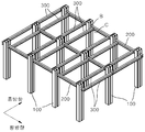
도 1은 본 발명의 일실시예에 따른 건축물의 기둥 보 연결구조의 주요골조들을 나타내는 사시도,
도 2는 도 1의 건축물의 기둥 보 연결구조에서 제1연결보와 SRC보로 인한 양방향 모멘트골조구성을 나타내는 평면도,
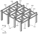
도 3은 도 1의 건축물의 기둥 보 연결구조에서 제4연결보가 접합된 상태를 나타내는 사시도,
도 4는 다른 실시예에 따른 건축물의 기둥 보 연결구조를 나타내는 평면도,
도 5 내지 도 11은 도 1의 건축물의 기둥 보 연결구조를 이용한 건축물의 시공절차를 나타내는 도면,
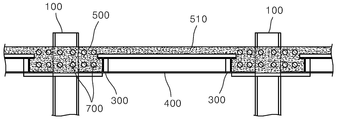
도 12는 도 11의 XII-XII선에 따른 단면도이다.BRIEF DESCRIPTION OF THE DRAWINGS FIG. 1 is a perspective view showing main frames of a column beam connection structure of a building according to an embodiment of the present invention;
FIG. 2 is a plan view showing a structure of a bi-directional moment frame due to the first connection beam and the SRC beam in the column beam connection structure of the building of FIG. 1;
Fig. 3 is a perspective view showing a state in which a fourth connecting beam is joined to a column beam connecting structure of the building of Fig. 1;
4 is a plan view showing a column beam connecting structure of a building according to another embodiment,
5 to 11 are views showing a construction procedure of a building using the column beam connecting structure of the building of FIG. 1,
12 is a sectional view taken along the line XII-XII in Fig.
이하, 첨부된 도면을 참조하여 본 발명의 바람직한 일실시예에 대하여 상세히 설명하기로 한다.
Hereinafter, a preferred embodiment of the present invention will be described in detail with reference to the accompanying drawings.
먼저, 도 1 및 도 2를 참조하면, 본 발명의 일실시에에 따른 건축물의 기둥과 보 연결구조는, 복수개의 기둥(100)들과, 제1연결보(200)들과, 제2연결보(300)들과, 제3연결보(400)들과, 콘크리트보(500)를 포함한다.
1 and 2, a column and a beam connection structure of a building according to an embodiment of the present invention includes a plurality of
상기 기둥(100)들은 횡 방향 및 종 방향을 따라 서로 이격되게 배치되어 있다. 상기 기둥(100)은 도시된 바와 같이 CFR 또는 일반 H형강을 적용할 수 있으나 이에 한정하지는 않는다. 여기서, 상기 횡 방향과 종 방향은 도시된 바와 같은 서로 직각방향을 이루는 방향이 아닌 통상적인 가로방향과 세로방향을 지칭하는 것으로 경사진 다양한 방향도 가능함을 뜻한다.
The
상기 제1연결보(200)들은 상기 기둥(100)들 사이 각각에 상기 횡 방향을 따라 배치되며, 상기 기둥(100)의 상부 측면에 단부가 접합(도 6의 B참조)되어 상기 기둥(100)들을 상기 횡 방향을 따라 서로 연결한다.
The
여기서, 상기 기둥(100)과 상기 제1연결보(200)는 강접합되어 콘크리트 타설 시 처짐 발생을 방지하고, 상기 횡 방향을 따라 모멘트골조를 이루도록 형성되는 것이 바람직하다.
Here, it is preferable that the
한편, 도면에서 상기 제1연결보(200)는 H형강보로 형성되어, 상기 기둥(100)과 일반 철골보 접합을 통하여 연결되어 있으나, 이는 바람직한 실시예로 다양한 골조 및 접합구조를 이룰 수 있음은 물론이다. 또한, 상기 연결보(200)는 도면에서 상기 기둥(100) 사이에 와이드 보로 이루어진 경우를 나타내었으나, 이는 일 실시예로 여러 개의 부재를 일직선으로 접합 연결하여 사용할 수 있음은 물론이다.
In the meantime, the
상기한 바에 따르면, 상기 건축물의 기둥 보 연결구조는 상기 제1연결보(200)가 종래와 같이 브라켓의 상면으로 얹는 방식으로 연결되는 것이 아니라, 상기 기둥(100)의 측면에 강접합 되는 구조이기 때문에, 브라켓과 같은 접합을 위한 별도의 부재가 불필요하여, 시공성을 향상시킬 수 있고, 공기 및 공사비를 저감시킬 수 있다. 또한, 상기 기둥(100)과 상기 제1연결보(200)가 강접합하기 때문에 타설 중 발생할 수 있는 처짐을 방지하여 구조적인 성능을 향상시킬 수 있다.
According to the above-described structure, the column connection structure of the building is structured such that the
상기 제2연결보(300)들은, 상기 종 방향을 따라 상기 기둥(100)을 중심으로 양측에 동일간격으로 이격되게 인접 배치된다. 상기 제2연결보(300)는 상기 제1연결보(200)들 사이 각각에 배치되고, 양단부가 상기 제1연결보(200)의 측면과 접합된다(도 7의 C참조). 도면에서, 상기 제2연결보(300)는 철골보 구조의 상기 제1연결보(200)와 동일하게 H형강 철골보를 적용한 경우를 나타내었으나, 이는 바람직한 실시예로 설계에 따라 변경 가능함은 물론이다.
The
한편, 상기 제2연결보(300)는 상기 제1연결보(200)와 강접합 또는 전단접합 중 접합종류를 선택할 수 있다. 가령, 상기 제2연결보(300)와 상기 제1연결보(200)를 강접하여 구조적인 강성을 향상시키고 및 모멘트 구조를 이루도록 할 수 있음은 물론, 상기 제2연결보(300)와 상기 제1연결보(200)를 전단접합하여 다양한 형태의 구조물에도 연결할 수도 있다. 여기서, 상기 제1연결보(200)와 상기 제2연결보(300)의 전단접합에 의한 다양한 형태의 구조물을 형성할 수 있는 점에 대해서는 후술하는 도 3에서 상세하게 살펴보기로 한다.
Meanwhile, the
상기 제3연결보(400)는, 상기 횡 방향을 따라 배치되며, 양단부가 이웃하는 상기 기둥(100)들 사이에 위치하는 상기 제2연결보(300)에 각각 접합되어 상기 제2연결보(300)의 처짐 및 향후 슬래브(510) 등의 수평하중을 지지하는 역할을 한다.
The
도 3을 참조하면, 상기 제4연결보(410)는, 상기 기둥(100)과 인접하게 상기 횡 방향을 따라 배치되며, 양단부가 상기 기둥(100)을 사이에 두고 인접하는 상기 제2연결보(300)에 각각 접합되어, 상기 제2연결보(300)의 처짐과 상기 콘크리트보(500)의 수평하중을 지지하는 역할을 한다.
3, the
여기서, 상기 제3연결보(400)와 상기 제4연결보(410)는 각각 단부가 상기 제2연결보(300)의 측면으로 전단접합을 통하여 연결되는 것이 바람직하나 이에 한정하는 것은 아니며, 배치간격 및 개수 등은 건축물의 구조와 설계에 따라 다양하게 할 수 있다.
The
상기 콘크리트보(500)는 상기 기둥(100)을 중심으로 마주하는 상기 제2연결보(300) 사이 공간에 상기 기둥(100)이 매립되도록 콘크리트를 타설하여 형성되며(도 2참조), 상기 종 방향을 따라 모멘트 골조를 이루도록 하는 역할을 한다. 상기 콘크리트보(500)는 상기 건축물의 설계에 따라 RC(Reinforced Concrete)보 또는 SRC(Steel Reinforced Concrete)보를 적용할 수 있다.
The
상기한 바에 따르면, 상기 건축물의 기둥 보 연결구조는, 상기 기둥(100)에 대하여 상기 제1연결보(200)를 통한 횡 방향 모멘트골조를 이룸과 동시에, 상기 콘크리트보(500)를 통한 종 방향 모멘트 골조를 이루어 양방향 모멘트 골조를 구현할 수 있도록 되어 있다. 때문에, 상기 건축물의 기둥 보 연결구조는 횡 방향 및 종 방향 모두에 대한 내진, 내풍 성능을 확보할 수 있어, 내진, 내풍에 저항하지 않는 지하 골조를 비롯하여 지상층 골조 등 다양하게 적용할 수 있다.
According to the above-described structure, the column beam connecting structure of the building provides a transverse moment frame structure with respect to the
한편, 상기 건축물의 기둥 보 연결구조는 전술한 바와 같이 상기 제1연결보(200)와 상기 제2연결보(300)가 전단 접합을 통하여 접합될 수 있다. 때문에, 상기 건축물의 기둥 보 연결구조는 상기한 전단접합을 통하여 상기 기둥(100)의 배열이 어긋나 평면상으로 비정형의 형태를 갖고 있는 건축물에도 적용할 수 있다.
Meanwhile, as described above, the column connection structure of the building can be joined to the
이에 대하여 도 4를 참조하여 살펴보면, 상기 기둥(100)들은 도 1과는 달리 종 방향 열에 대하여 어긋나게 각각 배치되어, 상기 기둥열이 지그재그 형태의 비정형을 이루고 있다.
Referring to FIG. 4, the
이러한 경우 상기 건축물의 기둥 보 연결구조는 상기 제2연결보(300a)의 단부와 상기 제1연결보(200)의 측면을 전단 접합을 통하여 연결하고(A부분), 이러한 전단접합을 통하여 동일한 간격을 갖도록 상기 제1연결보(200)에 대하여 상기 제2연결보(300)를 종 방향에 대하여 일정 각도 경사지게 연결한다. 그러면, 도시된 바와 같이 비정형의 자유로운 형태의 건축구조물에도 동일한 두께의 상기 콘크리트보(500)를 형성할 수 있다.
In this case, the column beam connection structure of the building connects the end of the
상기한 바와 같이 상기 건축물의 기둥 보 연결구조는 상기 제1연결보(200)와 상기 제2연결보(300)가 전단접합이 가능하기 때문에, 이러한 전단접합으로 인한 다양한 평면형태의 구조물에도 다양하게 적용할 수 있으며, 이러한 점은 최근의 건축물의 대부분 비정형임을 고려할 때 그 적용성이 상당히 높다 할 것이다.
As described above, since the
도 5 내지 도 11을 참조하여, 상기 건축물의 시공방법에 대하여 살펴보기로 한다.
5 to 11, a construction method of the building will be described.
우선, 도 5에 나타난 바와 같이, 횡 방향 및 종 방향을 따라 서로 이격되도록 복수개의 기둥(100)들을 설치한다. 이때, 상기 기둥(100)은 CFR 또는 일반 H형강을 적용한다.
First, as shown in Fig. 5, a plurality of
그런 다음, 도 6에 나타난 바와 같이 상기 기둥(100)의 양 측면에 제1연결보(200)들을 접합하여 상기 기둥(100)들을 상기 횡 방향을 따라 서로 연결한다. 여기서, 상기 제1연결보(200)는 단부가 상기 기둥(100)의 측면에 강접합을 통하여 연결되며, 이를 통해 접합부의 단순화 및 구조적 성능과 시공 중 안정성을 향상시킬 수 있다.
Then, as shown in FIG. 6, the first connection beams 200 are joined to both sides of the
상기한 바와 같이 상기 제1연결보(200)들을 서로 접합한 후에는, 도 7에 나타난 바와 같이 종 방향을 따라 상기 제2연결보(300)들을 연결한다. 이를 위해, 상기 기둥(100)을 중심으로 상기 기둥(100)의 양측에 인접하게 제2연결보(300)들을 종 방향으로 배치하고, 상기 제2연결보(300)들의 단부를 상기 제1연결보(200)에 전단 접합한다. 여기서, 상기 제2연결보(300)들 사이공간은 후에 콘크리트가 타설되어 상기 콘크리트보(500)가 형성되는 부분으로 상기 제2연결보(300)의 사이 간격은 콘크리트보(500)의 설계에 따라 조절할 수 있다.
After the first connection beams 200 are connected to each other as described above, the second connection beams 300 are connected along the longitudinal direction as shown in FIG. For this, the second connection beams 300 are arranged in the longitudinal direction adjacent to both sides of the
다음으로, 도 8에 나타난 바와 같이 이웃하는 상기 기둥(100)들 사이에 위치하는 상기 제2연결보(300)들 사이에 횡 방향을 따라 복수개의 제3연결보(400)들을 이격되게 설치하여, 타설 중 상기 제2연결보(300)의 처짐을 방지하고, 콘크리트 타설 시 수평방향으로 지지하도록 한다. 상기 제3연결보(400)는 양단부가 이웃하는 상기 제2연결보(300)의 측면으로 전단 접합한다.
Next, as shown in FIG. 8, a plurality of third connection beams 400 are installed apart from each other along the lateral direction between the second connection beams 300 positioned between the
아울러, 도시하지 않았지만, 건축물의 설계에 따라 상기 제3연결보(400)의 설치와 함께 이 과정에서 상기 제4연결보(500)를 설치할 수 있다. 한편, 상기 제3연결보(400)와 상기 제4연결보(500)는 건축물의 수평하중이나 보의 처짐 등을 고려하여 그 개수와 배치 간격 등을 달리할 수 있다.
In addition, although not shown, the
한편, 상기 제1연결보(200)에 대하여, 시공 중의 하중은 상기 기둥(100)으로부터 상기 제2연결보(300)와 만나는 짧은 부분이 지지하고, 영구하중은 상기 제2연결보(300)들 사이 상기 제1연결보(200)의 나머지 긴 부분이 지지하도록 되어 있다.
The load on the
이 후, 상기 기둥(100)을 중심으로 마주하는 상기 제2연결보(300)들 사이 공간에 콘크리트보(500)를 형성하여 상기 기둥(100)들을 상기 종 방향을 따라 서로 연결하고, 슬래브(510)를 형성한다.
Thereafter, a
도 9를 참조하면 우선 상기 기둥(100)을 사이에 두고 마주하는 상기 제2연결보(300)의 하부 플랜지에 제1데크부(610)를 설치하고, 상기 기둥(100)들 사이에 위치하는 상기 제2연결보(300)의 상부 플랜지에 제2데크부(620)를 설치한다. 여기서 미설명부호 600은 상기 제1데크부(610)와 상기 제2데크부(620)를 통칭하는 데크부를 나타낸다.
Referring to FIG. 9, a
이렇게 상기 제1데크부(610)와 제2데크부(620)의 설치를 완료하면, 도 10에 나타난 바와 같이 상기 콘크리트보(500)를 위하여 상기 제1데크부(610)의 상측으로 상기 기둥(100)들의 상기 종 방향을 따라 복수개의 철근(700)들을 이격되게 배근한다.
10, when the
그런 다음, 도 11에 나타난 바와 같이 상기 기둥(100)을 중심으로 마주하는 상기 제2연결보(300)들 사이 공간인 상기 제1데크부(610)의 상측으로 상기 기둥(100)이 매립되도록 콘크리트를 타설하여 콘크리트보(500)를 형성한다. 그리고 상기 콘크리트보(500)와 연결되도록 상기 제2데크부(620)의 상측으로 콘크리트를 타설하여 RC(Reinforced Concrete)모멘트 골조의 슬래브(510)를 형성한다. 도 12는 상기한 과정에 의하여 콘크리트 양생 후의 콘크리트보(500)와 슬래브(510)의 구조를 나타내는 단면도로서, 상기 콘크리트보(500)는 상기 기둥(100)이 매립되고 철근(700)이 배근되어 형성되고 상기 슬래브(510)는 상기 콘크리트보(500)와 연결된다.
Then, as shown in FIG. 11, the
한편 본 발명은 도면에 도시된 실시예를 참고로 설명되었으나 이는 예시적인 것에 불과하며, 본 기술 분야의 통상의 지식을 가진 자라면 이로부터 다양한 변형 및 균등한 다른 실시예가 가능하다는 점을 이해할 것이다. 따라서, 본 발명의 진정한 기술적 보호 범위는 첨부된 특허청구범위의 기술적 사상에 의하여 정해져야 할 것이다.
While the present invention has been particularly shown and described with reference to exemplary embodiments thereof, it is evident that many alternatives, modifications and variations will be apparent to those skilled in the art. Accordingly, the true scope of the present invention should be determined by the technical idea of the appended claims.
100 : 기둥
200 : 제1연결보
300, 300a : 제2연결보
400 : 제3연결보
410 : 제4연결보
500, 500a : 콘크리트보
510 : 슬래브
610 : 제1데크부
620 : 제2데크부
700 : 철근100: Column 200: First connection beam
300, 300a: second connection beam 400: third connection beam
410: fourth connecting
510: Slab 610: First deck section
620: second deck part 700: reinforcing bar
Claims (13)
상기 횡 방향을 따라 배치되며 단부가 상기 기둥의 측면에 접합되어 상기 기둥들을 상기 횡 방향을 따라 서로 연결하고, 상기 기둥과 모멘트 접합되어 상기 횡 방향을 따라 모멘트 골조를 이루도록 하는 복수개의 제1연결보들;
상기 종 방향을 따라 배치되되, 상기 기둥을 중심으로 상기 기둥의 양측에 인접하게 이격 배치되며, 상기 제1연결보와 접합되는 복수개의 제2연결보들; 및
상기 기둥을 중심으로 마주하는 상기 제2연결보들 사이 공간에 상기 기둥이 매립되도록 콘크리트를 타설하여, 상기 종 방향을 따라 모멘트 골조를 이루도록 하는 콘크리트보를 포함하는 것을 특징으로 하는 건축물의 기둥과 보 연결구조
A plurality of pillars spaced apart from each other along the lateral direction and the longitudinal direction;
A plurality of first connection rods disposed along the lateral direction and having ends connected to the side surfaces of the columns to connect the columns along the lateral direction and to be moment-bonded to the columns to form a moment frame along the lateral direction; ;
A plurality of second connection beams disposed along the longitudinal direction, the second connection beams being disposed adjacent to both sides of the column around the column, the second connection beams being joined to the first connection beam; And
And a concrete beam that pours concrete so that the column is embedded in a space between the second connection beams facing each other with respect to the column, thereby forming a moment frame along the longitudinal direction of the column.
상기 제1연결보는, 철골보로 형성되어 상기 기둥과 철골보 접합을 통하여 연결되는 것을 특징으로 하는 건축물의 기둥과 보 연결구조
The method according to claim 1,
Wherein the first connection view is formed of a steel beam and connected to the column through a steel beam connection.
상기 제1연결보와 상기 제2연결보는 각각 철골보로 형성되며, 상기 제2연결보는 상기 제1연결보에 강접합 또는 전단접합을 통하여 연결되는 것을 특징으로 하는 건축물의 기둥과 보 연결구조
The method according to claim 1,
Wherein the first connection beam and the second connection beam are respectively formed of steel beam beams and the second connection beam is connected to the first connection beam through strong bonding or shear bonding.
상기 기둥들은 상기 종 방향 열에 대하여 어긋나게 각각 배치되고, 상기 제2연결보는, 상기 제1연결보와 전단접합을 통하여 연결되어, 종 방향 열에 대하여 어긋나게 배치된 상기 기둥들에 대응하여 상기 제1연결보와 상기 종 방향에 대하여 경사지게 연결되는 것을 특징으로 하는 건축물의 기둥과 보 연결구조
The method according to claim 1,
Wherein the columns are arranged to be shifted from each other with respect to the longitudinal direction and the second connection view is connected to the first connection beam through the front end connection, And the column and the beam connection structure of the building are connected in an inclined manner with respect to the longitudinal direction.
상기 콘크리트보는, RC보 또는 SRC보인 것을 특징으로 하는 건축물의 기둥과 보 연결구조
The method according to claim 1,
Characterized in that the concrete view is RC beams or SRC beams.
상기 횡 방향을 따라 배치되며, 양단부가 이웃하는 상기 기둥들 사이에 위치하는 상기 제2연결보에 각각 접합되는 제3연결보를 더 포함하는 것을 특징으로 하는 건축물의 기둥과 보 연결구조
6. The method according to any one of claims 1 to 5,
Further comprising a third connection beam disposed along the lateral direction and being connected to the second connection beams located between the adjacent columns at both ends thereof,
상기 횡 방향을 따라 배치되며, 양단부가 상기 기둥을 사이에 두고 인접하는 상기 제2연결보에 각각 접합하는 제4연결보를 더 포함하는 것을 특징으로 하는 건축물의 기둥과 보 연결구조
The method according to claim 6,
And a fourth connection beam disposed along the lateral direction and joining to the second connection beams having opposite ends with the column interposed therebetween, respectively.
철골보로 이루어져 상기 기둥의 양 측면에 횡 방향을 따라 접합되고, 상기 기둥과 모멘트 접합되어 상기 횡 방향을 따라 모멘트 골조를 이루는 한 쌍의 제1연결보;
상기 기둥을 중심으로 종 방향을 따라 상기 기둥의 양측에 인접하게 이격 배치되며, 철골보로 이루어져 상기 제1연결보와 강접합 또는 전단접합을 통하여 연결되는 한 쌍의 제2연결보들; 및
상기 기둥을 중심으로 마주하는 상기 제2연결보들 사이 공간에 상기 기둥이 매립되도록 콘크리트를 타설하여 형성되며, 상기 종 방향을 따라 모멘트 골조를 이루는 콘크리트보;를 포함하는 것을 특징으로 하는 건축물의 기둥과 보 연결구조
Columns vertically erected and made of steel beams;
A pair of first connection beams made of steel bars and joined to both sides of the column along the transverse direction and moment-bonded to the columns to form a moment frame along the transverse direction;
A pair of second connection beams disposed adjacent to both sides of the column along a longitudinal direction about the column and made of steel beams and connected to the first connection beam through a strong junction or a front junction; And
And a concrete beam formed by placing concrete so that the column is embedded in a space between the second connection beams facing each other with the column as a center and forming a moment frame along the longitudinal direction of the column. Beam connection structure
횡 방향을 따라 상기 기둥의 양 측면에 제1연결보들을 설치하되, 상기 제1연결보들의 각 단부를 상기 기둥의 측면에 접합하여 상기 기둥들을 상기 횡 방향을 따라 서로 연결하는 단계;
종 방향을 따라 상기 기둥을 중심으로 상기 기둥의 양측에 인접하게 제2연결보들을 배치하고, 상기 제2연결보들의 단부 또는 측면부를 상기 제1연결보에 접합하는 단계;
상기 기둥을 중심으로 마주하는 상기 제2연결보들 사이 공간에 상기 기둥이 매립되도록 콘크리트를 타설하여, 상기 기둥들을 상기 종 방향을 따라 서로 연결하는 SRC보들을 형성하는 단계; 및
상기 SRC보들이 연결되도록 상기 제1연결보들의 상부로 콘크리트를 타설하여 슬래브를 형성하는 단계;를 포함하는 것을 특징으로 하는 건축물의 시공방법
Installing a plurality of pillars spaced apart along the lateral and longitudinal directions;
Connecting first ends of the first connection beams to the sides of the first connection rods to connect the first and second connection rods along the lateral direction;
Disposing second connection beams adjacent to both sides of the column around the column along the longitudinal direction and joining an end or a side portion of the second connection beams to the first connection beam;
Placing the concrete so that the column is embedded in a space between the second connection beams facing each other with the column as a center, thereby forming SRC beams connecting the columns along the longitudinal direction; And
And placing the concrete on top of the first connection beams so that the SRC beams are connected to each other to form a slab
상기 SRC보를 형성하는 단계는,
상기 기둥을 사이에 두고 마주하는 상기 제2연결보의 하부 플랜지에 제1데크부를 설치하는 단계와,
상기 제1데크부의 상측으로 상기 기둥들의 상기 종 방향을 따라 철근을 배근하는 단계와,
상기 제1데크부의 상부로 콘크리트를 타설 및 양생하는 단계를 포함하는 것을 특징으로 하는 건축물의 시공방법
10. The method of claim 9,
The step of forming the SRC beams includes:
Installing a first deck portion on a lower flange of the second connecting beam facing the column,
Placing a reinforcing bar along the longitudinal direction of the columns to the upper side of the first deck portion,
And placing and curing the concrete on the upper part of the first deck part
상기 슬래브를 형성하는 단계는,
상기 기둥들 사이에 위치하는 상기 제2연결보의 상부 플랜지에 제2데크부를 설치하는 단계와,
상기 SRC보와 연결되도록 상기 제2데크부의 상부로 콘크리트를 타설 및 양생하는 단계를 포함하는 것을 특징으로 하는 건축물의 시공방법
10. The method of claim 9,
The step of forming the slab may include:
Installing a second deck portion on an upper flange of the second connection beam located between the columns,
And placing and curing the concrete on the upper portion of the second deck portion so as to be connected to the SRC beam.
상기 SRC보들을 형성하기 전, 이웃하는 상기 기둥들 사이에 위치하는 상기 제2연결보들 사이에 상기 횡 방향을 따라 복수개의 제3연결보들을 배치하고, 상기 제3연결보의 양단부를 상기 제2연결보에 접합하여 상기 제3연결보들을 설치하는 단계를 더 포함하는 것을 특징으로 하는 건축물의 시공방법
10. The method of claim 9,
A plurality of third connection beams are disposed along the transverse direction between the second connection beams positioned between the adjacent columns before the SRC beams are formed, and both ends of the third connection beams are connected to the second And installing the third connection beams by joining the connection beams.
상기 SRC보들을 형성하기 전, 상기 기둥을 사이에 두고 인접하는 상기 제2연결보들 사이에 상기 횡 방향을 따라 복수개의 제4연결보들을 배치하고, 상기 제4연결보의 양단부를 상기 제2연결보에 접합하여 상기 제4연결보를 설치하는 단계를 더 포함하는 것을 특징으로 하는 건축물의 시공방법13. The method of claim 12,
A plurality of fourth connection beams are disposed along the transverse direction between the second connection beams adjacent to each other with the column interposed therebetween before the SRC beams are formed and both end portions of the fourth connection beams are connected to the second connection And installing the fourth connection beam by joining the first connection beam and the second connection beam to each other.
Applications Claiming Priority (2)
| Application Number | Priority Date | Filing Date | Title |
|---|---|---|---|
| KR20150172695 | 2015-12-04 | ||
| KR1020150172695 | 2015-12-04 |
Publications (2)
| Publication Number | Publication Date |
|---|---|
| KR20170066193A true KR20170066193A (en) | 2017-06-14 |
| KR102309544B1 KR102309544B1 (en) | 2021-10-07 |
Family
ID=59218403
Family Applications (1)
| Application Number | Title | Priority Date | Filing Date |
|---|---|---|---|
| KR1020160053536A KR102309544B1 (en) | 2015-12-04 | 2016-04-29 | Connecting structure of beam and column of a building and method of manufacturing using the same |
Country Status (1)
| Country | Link |
|---|---|
| KR (1) | KR102309544B1 (en) |
Cited By (3)
| Publication number | Priority date | Publication date | Assignee | Title |
|---|---|---|---|---|
| KR20190000432A (en) * | 2017-06-23 | 2019-01-03 | 심남주 | Coupling structure of column and girder having single girder in lateral direction, double girder in backward direction and concrete part around the column |
| KR20190124561A (en) * | 2018-04-26 | 2019-11-05 | 주식회사 포스코 | Connecting sturcture between column and wide beam and floor structure |
| KR102277253B1 (en) * | 2020-11-26 | 2021-07-13 | 코오롱이앤씨 주식회사 | Rapid construction process Rahmen structure system and construction methods for utilizing the CTS slab |
Citations (4)
| Publication number | Priority date | Publication date | Assignee | Title |
|---|---|---|---|---|
| KR100856723B1 (en) * | 2007-03-28 | 2008-09-04 | 박무용 | System and method for underground downward construction using cantilever type steel frame |
| KR101034399B1 (en) * | 2008-02-18 | 2011-05-16 | (주)바로건설기술 | Drop Panel Structure Of Lattice-Form And Construction Method Thereof |
| KR20150029512A (en) | 2013-09-09 | 2015-03-18 | 주식회사 씨엠파트너스건축사사무소 | The horizontal structural frame and the underground construction methods using it |
| KR101536659B1 (en) * | 2014-06-11 | 2015-07-14 | 주식회사 반석티브이에스 | Prestressed steel composite structure |
-
2016
- 2016-04-29 KR KR1020160053536A patent/KR102309544B1/en active IP Right Grant
Patent Citations (4)
| Publication number | Priority date | Publication date | Assignee | Title |
|---|---|---|---|---|
| KR100856723B1 (en) * | 2007-03-28 | 2008-09-04 | 박무용 | System and method for underground downward construction using cantilever type steel frame |
| KR101034399B1 (en) * | 2008-02-18 | 2011-05-16 | (주)바로건설기술 | Drop Panel Structure Of Lattice-Form And Construction Method Thereof |
| KR20150029512A (en) | 2013-09-09 | 2015-03-18 | 주식회사 씨엠파트너스건축사사무소 | The horizontal structural frame and the underground construction methods using it |
| KR101536659B1 (en) * | 2014-06-11 | 2015-07-14 | 주식회사 반석티브이에스 | Prestressed steel composite structure |
Cited By (3)
| Publication number | Priority date | Publication date | Assignee | Title |
|---|---|---|---|---|
| KR20190000432A (en) * | 2017-06-23 | 2019-01-03 | 심남주 | Coupling structure of column and girder having single girder in lateral direction, double girder in backward direction and concrete part around the column |
| KR20190124561A (en) * | 2018-04-26 | 2019-11-05 | 주식회사 포스코 | Connecting sturcture between column and wide beam and floor structure |
| KR102277253B1 (en) * | 2020-11-26 | 2021-07-13 | 코오롱이앤씨 주식회사 | Rapid construction process Rahmen structure system and construction methods for utilizing the CTS slab |
Also Published As
| Publication number | Publication date |
|---|---|
| KR102309544B1 (en) | 2021-10-07 |
Similar Documents
| Publication | Publication Date | Title |
|---|---|---|
| KR101030419B1 (en) | Joint structure of vertical member and horizontal member | |
| KR100957571B1 (en) | Anti-buckling reinforcing structure for asymmetric steel beam at slim floor system and its construction method | |
| KR101880494B1 (en) | Core wall seismic reinforcement structure and construction method of the same | |
| JP2008025125A (en) | Column unit and construction method for building using it | |
| KR101011252B1 (en) | Rigid-frame bridge frame for reinforcing negative moment part and rigid-frame bridge having it | |
| JP5124146B2 (en) | Seismic control building | |
| KR20170066193A (en) | Connecting structure of beam and column of a building and method of manufacturing using the same | |
| KR102029301B1 (en) | Prefabricated column assembly with foundation reinforcement part | |
| JP6633362B2 (en) | Reinforcement structure of steel concrete frame | |
| JP2008031682A (en) | Aseismically supporting structure during temporary bearing of building, and aseismically supporting method during temporary bearing of building | |
| JPH10152998A (en) | Earthquake-resistant reinforcing structure of existing building | |
| KR100856723B1 (en) | System and method for underground downward construction using cantilever type steel frame | |
| KR101463106B1 (en) | The precast concrete pillar and girder connecting structure for a building | |
| JP4964528B2 (en) | Floor structure of steel structure building and construction method of floor structure | |
| JP6508866B2 (en) | Column-beam frame | |
| JP6585142B2 (en) | Tower structure structure, composite reinforcing material, and method of manufacturing composite reinforcing material | |
| JP2005036598A (en) | Damping structure | |
| KR20180026286A (en) | Grid precast concrete structure and constructing method thereof | |
| JP6849491B2 (en) | Exposed column base structure of steel columns and its construction method | |
| JP5872332B2 (en) | Seismic reinforcement method for buildings | |
| JP4898317B2 (en) | Seismic wall installation structure | |
| JP4936172B2 (en) | Beam-column joint structure and building frame structure | |
| CN104727468A (en) | Superimposed slab type shear wall | |
| JP7316910B2 (en) | building | |
| KR102452802B1 (en) | A construction method to use the seismic resistant precast concrete members |
Legal Events
| Date | Code | Title | Description |
|---|---|---|---|
| A201 | Request for examination | ||
| E902 | Notification of reason for refusal | ||
| E701 | Decision to grant or registration of patent right | ||
| GRNT | Written decision to grant |