KR20170051279A - Liquid ejecting device, head, and liquid filling method - Google Patents
Liquid ejecting device, head, and liquid filling method Download PDFInfo
- Publication number
- KR20170051279A KR20170051279A KR1020160137766A KR20160137766A KR20170051279A KR 20170051279 A KR20170051279 A KR 20170051279A KR 1020160137766 A KR1020160137766 A KR 1020160137766A KR 20160137766 A KR20160137766 A KR 20160137766A KR 20170051279 A KR20170051279 A KR 20170051279A
- Authority
- KR
- South Korea
- Prior art keywords
- liquid
- liquid containing
- head
- containing unit
- unit
- Prior art date
Links
Images


Classifications
-
- B—PERFORMING OPERATIONS; TRANSPORTING
- B41—PRINTING; LINING MACHINES; TYPEWRITERS; STAMPS
- B41J—TYPEWRITERS; SELECTIVE PRINTING MECHANISMS, i.e. MECHANISMS PRINTING OTHERWISE THAN FROM A FORME; CORRECTION OF TYPOGRAPHICAL ERRORS
- B41J2/00—Typewriters or selective printing mechanisms characterised by the printing or marking process for which they are designed
- B41J2/005—Typewriters or selective printing mechanisms characterised by the printing or marking process for which they are designed characterised by bringing liquid or particles selectively into contact with a printing material
- B41J2/01—Ink jet
- B41J2/135—Nozzles
- B41J2/14—Structure thereof only for on-demand ink jet heads
- B41J2/14016—Structure of bubble jet print heads
-
- B—PERFORMING OPERATIONS; TRANSPORTING
- B41—PRINTING; LINING MACHINES; TYPEWRITERS; STAMPS
- B41J—TYPEWRITERS; SELECTIVE PRINTING MECHANISMS, i.e. MECHANISMS PRINTING OTHERWISE THAN FROM A FORME; CORRECTION OF TYPOGRAPHICAL ERRORS
- B41J2/00—Typewriters or selective printing mechanisms characterised by the printing or marking process for which they are designed
- B41J2/005—Typewriters or selective printing mechanisms characterised by the printing or marking process for which they are designed characterised by bringing liquid or particles selectively into contact with a printing material
- B41J2/01—Ink jet
- B41J2/17—Ink jet characterised by ink handling
- B41J2/175—Ink supply systems ; Circuit parts therefor
- B41J2/17503—Ink cartridges
-
- B—PERFORMING OPERATIONS; TRANSPORTING
- B41—PRINTING; LINING MACHINES; TYPEWRITERS; STAMPS
- B41J—TYPEWRITERS; SELECTIVE PRINTING MECHANISMS, i.e. MECHANISMS PRINTING OTHERWISE THAN FROM A FORME; CORRECTION OF TYPOGRAPHICAL ERRORS
- B41J2/00—Typewriters or selective printing mechanisms characterised by the printing or marking process for which they are designed
- B41J2/005—Typewriters or selective printing mechanisms characterised by the printing or marking process for which they are designed characterised by bringing liquid or particles selectively into contact with a printing material
- B41J2/01—Ink jet
- B41J2/17—Ink jet characterised by ink handling
- B41J2/175—Ink supply systems ; Circuit parts therefor
- B41J2/17503—Ink cartridges
- B41J2/17506—Refilling of the cartridge
- B41J2/17509—Whilst mounted in the printer
-
- B—PERFORMING OPERATIONS; TRANSPORTING
- B41—PRINTING; LINING MACHINES; TYPEWRITERS; STAMPS
- B41J—TYPEWRITERS; SELECTIVE PRINTING MECHANISMS, i.e. MECHANISMS PRINTING OTHERWISE THAN FROM A FORME; CORRECTION OF TYPOGRAPHICAL ERRORS
- B41J2/00—Typewriters or selective printing mechanisms characterised by the printing or marking process for which they are designed
- B41J2/005—Typewriters or selective printing mechanisms characterised by the printing or marking process for which they are designed characterised by bringing liquid or particles selectively into contact with a printing material
- B41J2/01—Ink jet
- B41J2/17—Ink jet characterised by ink handling
- B41J2/175—Ink supply systems ; Circuit parts therefor
- B41J2/17503—Ink cartridges
- B41J2/17513—Inner structure
-
- B—PERFORMING OPERATIONS; TRANSPORTING
- B41—PRINTING; LINING MACHINES; TYPEWRITERS; STAMPS
- B41J—TYPEWRITERS; SELECTIVE PRINTING MECHANISMS, i.e. MECHANISMS PRINTING OTHERWISE THAN FROM A FORME; CORRECTION OF TYPOGRAPHICAL ERRORS
- B41J2/00—Typewriters or selective printing mechanisms characterised by the printing or marking process for which they are designed
- B41J2/005—Typewriters or selective printing mechanisms characterised by the printing or marking process for which they are designed characterised by bringing liquid or particles selectively into contact with a printing material
- B41J2/01—Ink jet
- B41J2/17—Ink jet characterised by ink handling
- B41J2/175—Ink supply systems ; Circuit parts therefor
- B41J2/17503—Ink cartridges
- B41J2/1752—Mounting within the printer
- B41J2/17523—Ink connection
-
- B—PERFORMING OPERATIONS; TRANSPORTING
- B41—PRINTING; LINING MACHINES; TYPEWRITERS; STAMPS
- B41J—TYPEWRITERS; SELECTIVE PRINTING MECHANISMS, i.e. MECHANISMS PRINTING OTHERWISE THAN FROM A FORME; CORRECTION OF TYPOGRAPHICAL ERRORS
- B41J2/00—Typewriters or selective printing mechanisms characterised by the printing or marking process for which they are designed
- B41J2/005—Typewriters or selective printing mechanisms characterised by the printing or marking process for which they are designed characterised by bringing liquid or particles selectively into contact with a printing material
- B41J2/01—Ink jet
- B41J2/17—Ink jet characterised by ink handling
- B41J2/175—Ink supply systems ; Circuit parts therefor
- B41J2/17503—Ink cartridges
- B41J2/17553—Outer structure
-
- B—PERFORMING OPERATIONS; TRANSPORTING
- B41—PRINTING; LINING MACHINES; TYPEWRITERS; STAMPS
- B41J—TYPEWRITERS; SELECTIVE PRINTING MECHANISMS, i.e. MECHANISMS PRINTING OTHERWISE THAN FROM A FORME; CORRECTION OF TYPOGRAPHICAL ERRORS
- B41J25/00—Actions or mechanisms not otherwise provided for
- B41J25/24—Case-shift mechanisms; Fount-change arrangements
-
- B—PERFORMING OPERATIONS; TRANSPORTING
- B41—PRINTING; LINING MACHINES; TYPEWRITERS; STAMPS
- B41J—TYPEWRITERS; SELECTIVE PRINTING MECHANISMS, i.e. MECHANISMS PRINTING OTHERWISE THAN FROM A FORME; CORRECTION OF TYPOGRAPHICAL ERRORS
- B41J29/00—Details of, or accessories for, typewriters or selective printing mechanisms not otherwise provided for
- B41J29/02—Framework
-
- B—PERFORMING OPERATIONS; TRANSPORTING
- B41—PRINTING; LINING MACHINES; TYPEWRITERS; STAMPS
- B41J—TYPEWRITERS; SELECTIVE PRINTING MECHANISMS, i.e. MECHANISMS PRINTING OTHERWISE THAN FROM A FORME; CORRECTION OF TYPOGRAPHICAL ERRORS
- B41J2/00—Typewriters or selective printing mechanisms characterised by the printing or marking process for which they are designed
- B41J2/005—Typewriters or selective printing mechanisms characterised by the printing or marking process for which they are designed characterised by bringing liquid or particles selectively into contact with a printing material
- B41J2/01—Ink jet
- B41J2/135—Nozzles
- B41J2/14—Structure thereof only for on-demand ink jet heads
- B41J2/14016—Structure of bubble jet print heads
- B41J2002/14169—Bubble vented to the ambience
Abstract
Description
본 발명은 액체 토출 장치, 헤드 및 액체 충전 방법에 관한 것이다.The present invention relates to a liquid ejecting apparatus, a head, and a liquid filling method.
잉크 등의 액체를 토출하여 화상이나 문자를 인쇄하는 액체 토출 장치(예를 들어, 잉크젯 인쇄 장치)로서, 캐리지에 잉크 탱크를 갖는 헤드를 탑재하고, 캐리지와 다른 위치에 잉크를 저장하는 메인 탱크가 배치되는 형태를 갖는 것이 있다. 일본 특허 공개 공보 번호 2004-249560은, 메인 탱크 내의 잉크를 튜브를 통해 헤드 측의 잉크 탱크에 공급하고, 토출 유닛으로부터 잉크를 토출하는 액체 토출 장치를 개시한다. 일본 특허 공개 공보 번호 2004-249560에 개시된 액체 토출 장치에서는, 헤드 내의 부압에 응답하여 유로를 개폐하는 밸브 유닛이 튜브와 헤드 사이에 연결되어 있다.2. Description of the Related Art A liquid ejecting apparatus (e.g., an inkjet printing apparatus) for ejecting a liquid such as ink to print an image or a character is provided with a main tank for mounting a head having an ink tank on a carriage, And the like. Japanese Laid-Open Patent Publication No. 2004-249560 discloses a liquid discharging apparatus that supplies ink in a main tank to an ink tank on a head side through a tube and discharges ink from the discharging unit. In the liquid discharging apparatus disclosed in Japanese Patent Laid-Open Publication No. 2004-249560, a valve unit for opening and closing the flow path in response to a negative pressure in the head is connected between the tube and the head.
본 발명의 액체 토출 장치는, 내부에 액체를 저장할 수 있는 액체 수납 용기와; 캐리지 상에 제공되며, 내부에 액체를 유지할 수 있는 유지 부재를 갖는 액체 수납 유닛과 액체를 토출하는 액체 토출 유닛을 포함하는 헤드와; 상기 액체 수납 용기를 상기 액체 수납 유닛에 연결하며, 상기 액체 수납 용기의 내부에 저장된 액체를 상기 액체 수납 유닛에 공급하는 가요성 부재를 포함하며, 상기 액체 수납 유닛의 내부 공간은 직육면체 형상을 갖고, 상기 헤드가 상기 캐리지 상에 제공된 자세에서, 상기 내부 공간에서의 수평면을 따른 단면의 긴 변 길이를, 상기 유지 부재의 중력 방향을 따르는 길이로 나누어 얻은 값이 1.5 이상이다.A liquid discharging apparatus of the present invention includes: a liquid containing container capable of storing a liquid therein; A head provided on the carriage and including a liquid containing unit having a holding member capable of holding a liquid therein, and a liquid discharge unit for discharging liquid; And a flexible member that connects the liquid storage container to the liquid storage unit and supplies the liquid stored in the liquid storage container to the liquid storage unit, wherein the inner space of the liquid storage unit has a rectangular parallelepiped shape, The value obtained by dividing the long side length of the cross section along the horizontal plane in the internal space by the length along the gravity direction of the holding member in the posture in which the head is provided on the carriage is 1.5 or more.
본 발명의 추가적인 특징은 (첨부된 도면을 참고한) 예시적인 실시형태에 대한 이하의 설명으로부터 명확해질 것이다.Additional features of the present invention will become apparent from the following description of exemplary embodiments (with reference to the accompanying drawings).
도 1은 액체 토출 장치의 사시도이다.
도 2는 도 1의 액체 토출 장치의 액체 공급 시스템을 나타내는 단면도이다.
도 3은 도 1의 액체 토출 장치에 탑재되는 헤드 및 헤드에 연결되는 가요성 부재의 조인트를 나타내는 단면도이다.
도 4는 도 3의 헤드를 나타내는 사시도이다.
도 5는 V-V 선을 따르는 도 4의 헤드의 단면도이다.
도 6은 액체 토출 장치에 탑재되는 헤드의 개략적인 단면도이다.
도 7은 액체 토출 장치에 탑재되는 헤드의 개략적인 단면도이다.
도 8a는 액체 토출 장치에 탑재되는 헤드의 사시도이다.
도 8b는 VIIIB-VIIIB 선을 따르는 도 8a의 헤드의 개략적인 단면도이다.
도 8c는 도 8a의 헤드의 평면도이다.
도 9a는 액체 토출 장치에 탑재되는 헤드에 1개의 액체 수납 유닛이 있는 경우의 평면도이다.
도 9b는 복수의 액체 수납 유닛이 있는 경우의 평면도이다.
도 10은 액체 토출 장치에 탑재되는 헤드, 가요성 부재, 및 이들 사이의 연결 유닛의 단면도이다.
도 11은 액체 토출 장치에 탑재되는 헤드의 내부에 배치되는 유지 부재의 섬유의 확대도이다.
도 12a는 도 11의 유지 부재의 각 섬유의 단면도이다.
도 12b는 도 11의 유지 부재의 각 섬유의 단면도이다.1 is a perspective view of a liquid discharge device.
Fig. 2 is a sectional view showing the liquid supply system of the liquid discharge apparatus of Fig. 1;
3 is a cross-sectional view showing a joint of a flexible member connected to a head and a head mounted on the liquid discharging apparatus of Fig. 1;
Fig. 4 is a perspective view showing the head of Fig. 3;
5 is a cross-sectional view of the head of FIG. 4 along the VV line.
6 is a schematic cross-sectional view of a head mounted on the liquid discharge device.
7 is a schematic cross-sectional view of a head mounted on the liquid discharge device.
8A is a perspective view of a head mounted on a liquid discharge device.
8B is a schematic cross-sectional view of the head of FIG. 8A along line VIIIB-VIIIB.
8C is a plan view of the head of FIG. 8A.
Fig. 9A is a plan view showing a case in which one liquid containing unit is provided in a head mounted on the liquid discharge apparatus. Fig.
Fig. 9B is a plan view showing a case in which a plurality of liquid containing units are provided.
10 is a cross-sectional view of a head, a flexible member, and a connecting unit therebetween mounted on the liquid discharging apparatus.
11 is an enlarged view of the fibers of the holding member disposed inside the head mounted on the liquid discharging apparatus.
12A is a cross-sectional view of each fiber of the holding member of FIG.
12B is a cross-sectional view of each fiber of the holding member of Fig.
그러나, 일본 특허 공개 공보 번호 2004-249560에 개시된 액체 토출 장치는 이하의 문제를 갖는 다는 것이 발견되었다. 즉, 액체가 토출되는 경우에, 헤드를 탑재하는 캐리지의 이동, 헤드에 가해지는 충격 등에 의해 헤드의 액체 수납 유닛(잉크 탱크)에 수납된 액체(잉크)의 액면에 진동이 발생하고, 액면이 요동한다. 액면이 요동하는 경우, 액체 수납 유닛의 내부에서 액체에 의한 압력이 불안정해지고, 압력의 불안정함이 헤드 내부의 액체에 전달된다. 이에 의해, 헤드로부터 액체가 불안정하게 토출되는 경우가 있다.However, it has been found that the liquid discharge apparatus disclosed in Japanese Patent Application Laid-Open No. 2004-249560 has the following problems. That is, when the liquid is ejected, vibration occurs in the liquid surface of the liquid (ink) stored in the liquid containing unit (ink tank) of the head due to the movement of the carriage on which the head is mounted and the impact applied to the head, Shake. When the liquid level fluctuates, the pressure caused by the liquid inside the liquid containing unit becomes unstable, and the unstable pressure is transferred to the liquid inside the head. Thereby, the liquid may be unstably discharged from the head.
본 발명에 따르면, 이러한 상황을 감안하여, 액체 수납 유닛의 내부에서 액체를 안정되게 수납하는 액체 토출 장치, 헤드 및 액체 충전 방법이 제공된다.According to the present invention, in view of this situation, there is provided a liquid discharging device, a head, and a liquid filling method for stably storing liquid inside the liquid containing unit.
(제1 실시형태)(First Embodiment)
이하, 본 발명의 제1 실시형태에 따른 액체 토출 장치 및 헤드에 대해서 설명한다.Hereinafter, the liquid discharging apparatus and the head according to the first embodiment of the present invention will be described.
도 1은, 본 발명의 실시형태에 따라 액체 토출 장치(잉크젯 인쇄 장치)(1)의 외장이 분리된 상태의 사시도를 나타낸다. 도 2는, 액체 토출 장치(1)에 탑재되는 헤드(5) 및 헤드(5) 내부에 형성된 유로의 개략적인 단면도를 도시한다.1 shows a perspective view of a liquid ejection apparatus (inkjet printing apparatus) 1 according to an embodiment of the present invention in a state in which its exterior is separated. Fig. 2 shows a schematic sectional view of a flow path formed inside the
헤드(5)는, 캐리지(지지 부재)(31)에 탑재될 수 있도록 구성되어 있고, 캐리지(31)의 상부에 제공되어 있는 조인트(도시하지 않음)에 연결됨으로써, 캐리지 상에 제공된다. 헤드(5)는 튜브 등의 가요성 부재(3)에 연결되어 있고, 가요성 부재(3)의 다른 단부는 액체 수납 용기(2)에 연결된다. 헤드(5)가 캐리지(31)에 부착되는 경우, 헤드(5)는 조인트 및 가요성 부재(3)를 통해 액체 수납 용기(2)와 연통하게 된다. 액체 토출 장치(1)는, 시리얼-스캐닝-방식의 인쇄 장치이며, 가이드축에 의해 캐리지(31)가 주주사 방향으로 이동가능하게 안내된다. 캐리지(31)는, 캐리지 모터 및 그 구동력을 전달하는 벨트 등의 구동력 전달 기구에 의해, 주주사 방향으로 왕복한다.The
캐리지(31)에는, 액체 토출 유닛(잉크 토출 유닛)(8)과, 그 액체 토출 유닛(8)에 액체(잉크)를 공급하는 액체 수납 유닛(잉크 탱크 유닛)(25)을 일체로 포함하는 헤드(5)가 탑재되어 있다. 위에서 언급된 바와 같이, 캐리지(31)는 헤드(5)를 지지할 수 있도록 구성되어 있다. 헤드(5)의 액체 수납 유닛(25)은 내부에 액체를 저장할 수 있도록 구성되어 있다. 액체 수납 유닛과 액체 토출 유닛은 일체화되지 않을 수 있고 개별적으로 형성될 수 있다는 것을 유의하라.The
시트 등의 인쇄 매체는, 반송 롤러에 의해 캐리지(31)의 주주사 방향에 직교하는 부주사 방향으로 반송된다. 액체 토출 장치(1)는, 액체 토출 유닛(8)을 주주사 방향으로 이동시키면서, 플래튼 상의 인쇄 매체의 인쇄 영역에 액체를 토출하는 인쇄 동작과, 그 인쇄 폭에 대응하는 거리만큼 인쇄 매체를 부주사 방향으로 반송하는 반송 동작을 반복한다. 이에 의해, 인쇄 매체 위에 순차적으로 화상을 인쇄(형성)한다.A printing medium such as a sheet is conveyed by a conveying roller in the sub-scanning direction orthogonal to the main-scanning direction of the
헤드(5)의 액체 토출 유닛(8)에는, 복수의 토출 포트와, 복수의 토출 포트와 연통하는 복수의 압력 챔버와, 압력 챔버와 연통하는 복수의 유로가 각각 형성된다. 액체는, 헤드(5)의 액체 수납 유닛(25)으로부터, 액체 토출 유닛(8)의 내부에 형성된 압력 챔버에 각각의 유로를 통해 공급된다. 각 압력 챔버는, 에너지 발생 소자로서 예를 들어 발열 소자(전기/열 변환기)를 구비한다. 배선을 통해서 발열 소자가 급전되고, 그 발열 소자로부터 열 에너지를 발생시킴으로써, 압력 챔버 내의 액체를 가열하여 막 비등에 의해 기포를 발생시킨다. 이때의 기포 발생 에너지에 의해 토출 포트로부터 액적이 토출된다. 에너지 발생 소자로서는, 압전 소자 등을 사용할 수 있다.In the
헤드(5)는 액체 수납 유닛(25)을 포함하고 있다. 헤드(5)의 액체 수납 유닛(25)은 주로 케이스(16)에 커버 부재(17)가 부착되어서 형성된다. 액체 수납 유닛(25)의 내부에, 액체 토출 유닛(8)에 공급되는 액체가 일단 저장된다.The
도 2에 도시된 바와 같이, 헤드(5)는 가요성 부재(3)를 통해 액체 수납 용기(2)에 연결되어 있다. 헤드 측의 가요성 부재(3)의 단부에는 조인트(6)가 부착된다. 위에서 언급된 바와 같이, 액체 토출 장치(1)에는, 비교적 많은 양의 액체를 수납하는 액체 수납 용기(2)가 캐리지(31)의 외부에 배치되어 있다. 액체 수납 용기(2)는, 캐리지(31)로부터 다른 위치에 배치되고, 또한 튜브 등의 가요성 부재(3)를 통해 캐리지(31)에 탑재된 헤드(5)의 액체 수납 유닛(25)에 연결되어 있다. 액체 수납 용기(2)에는 액체가 직접 저장되어 있다. 액체의 저장량을 증가시키기 위해서, 액체 수납 용기(2)의 내부에는 스펀지 등의 액체를 유지하기 위한 유지 부재는 배치되지 않는 것이 바람직하다. 위에서 언급된 바와 같이, 액체 수납 용기(2)는 가요성 부재(3)에 의해 헤드(5)에 연결되고, 액체 수납 용기(2) 내의 액체는 헤드(5)의 액체 수납 유닛(25)에 연속적으로 공급된다.As shown in Fig. 2, the
도 3은, 헤드(5)와, 헤드(5)에 연결되는 가요성 부재(3)의 헤드(5) 측에 부착된 조인트(6)의 단면도를 도시한다. 도 4는 헤드(5)의 사시도를 나타낸다. 헤드(5)에는 파이프 형상 유로로서의 액체 공급관(7)이 제공된다. 액체 공급관(7)은, 헤드(5)의 커버 부재(17)로부터, 액체 수납 용기의 외측을 향하는 방향(조인트(6)를 향하는 방향)으로 돌출한다. 액체 공급관(7)은 조인트(6)의 공급로(26)에 연결되고, 이에 의해 헤드(5)를 조인트(6)에 연결한다. 결과적으로, 헤드(5)는 가요성 부재(3)에 연결된다.3 shows a cross-sectional view of the joint 5 attached to the
헤드(5)의 내부에는, 액체 토출 유닛(8)의 토출 포트 및 액체 공급관(7)의 개구부를 제외하고, 밀봉 상태가 형성된다. 조인트(6)의 공급로(26) 내측에 탄성 부재(9)가 배치된다. 탄성 부재(9)가 액체 공급관(7)의 외주부와 조인트(6)의 공급로(26)의 내주부 사이에 배치됨으로써, 헤드(5)의 액체 공급관(7)과 조인트(6)의 공급로(26) 사이의 공간을 밀봉한다. 이에 의해, 액체가 조인트(6)로부터 헤드(5)에 바람직하게 공급될 수 있다.In the inside of the
위에서 언급된 바와 같이, 가요성 부재(3)에 있어서의 헤드(5)에 연결된 측의 다른 단부 측에는 액체 수납 용기(2)가 연결되어 있다. 액체 수납 용기(2)는, 주로, 액체 수납 유닛(10)과 버퍼 챔버(11)로 분할된다. 액체 수납 유닛(10)은, 연통 개구(12)을 제외하고, 내부의 밀봉을 확보한다. 액체 수납 유닛(10)에는 연결 튜브(13)가 부착된다. 액체 수납 유닛(10)의 내부는 연결 튜브(13)의 유로와 연통하고, 그들은 서로 연결되어 있다.As described above, the
연결 튜브(13)는, 액체 수납 유닛(10)의 중력 방향의 최하 위치 부근에 제공된다. 버퍼 챔버(11)에는 외기 연통 구멍(14)이 제공된다. 버퍼 챔버(11)의 내부는 외기와 연통하고 있다. 액체 수납 유닛(10)은 연통로(15) 및 연통 개구(12)를 통해 버퍼 챔버(11)와 연통하고 있다. 버퍼 챔버(11)는, 액체 수납 용기(2)의 환경 온도가 높거나 환경 압력이 낮은 경우, 액체 수납 유닛(10)의 내부 또는 헤드(5) 내의 공기의 팽창에 대응하는 액체를 배출하기 위한 공간이다.The connecting
도 2에 도시된 바와 같이, 액체 공급로에서 외기와 접촉하는 부분은, 헤드(5)의 액체 토출 유닛(8)의 토출 포트와 액체 수납 용기(2)의 연통 개구(12) 뿐이다. 또한, 헤드(5)를 액체 토출 장치(1)에 탑재한 상태에서, 액체 토출 유닛(8)은 액체 수납 용기(2)의 수위보다 높은 위치에 배치된다. 따라서, 수두차에 의해, 액체 토출 유닛(8)의 내부에 부압이 형성된다. 이 부압에 의해, 액체 토출 유닛(8)에서의 토출 포트로부터의 액체의 낙하를 방지하고, 이에 의해 액체 토출 유닛(8)의 내부에 액체를 유지한다. 이 구성에서는, 수두차는, 액체 토출 유닛(8)의 토출 포트의 위치와 액체 수납 용기(2)의 연통 개구(12)의 위치 사이의 수두차가 된다. 따라서, 액체 수납 용기(2)에서의 액체 수납 유닛(10)의 내부에서 액체의 액면이 어떤 위치에 있어도, 액체 토출 유닛(8)의 내부에 일정한 부압을 유지하는 것이 가능하게 된다.2, only the discharge port of the
또한, 인쇄에 의해 액체 토출 유닛(8)의 토출 포트로부터의 액체의 토출이 계속되는 경우, 헤드(5) 내의 부압이 증가하게 된다. 액체 토출 유닛(8) 내부에서의 부압이, 액체 수납 용기(2)로부터 헤드(5)까지의 액체 공급로의 유동 저항과, 연통 개구(12)에서의 메니스커스력의 합보다 커지는 경우, 연통 개구(12)로부터 액체 수납 유닛(10)에 외기가 공급된다. 따라서, 가요성 부재(3)를 통해 액체 수납 용기(2)로부터 헤드(5)에 액체가 공급된다. 결과적으로, 헤드(5) 내의 부압이 감소되어, 인쇄 전의 상태가 회복된다. 그로 인해, 액체 토출 유닛(8) 내부의 부압이 일정하게 유지된다.Further, when the discharge of the liquid from the discharge port of the
상술한 일련의 동작을 반복함으로써, 액체 토출 장치(1)에서의 액체 수납 용기(2)로부터 헤드(5)에의 액체의 공급이 허용된다.By repeating the above-described series of operations, supply of the liquid from the
캐리지(31)가 주주사 방향으로 이동함으로써, 헤드(5)가 이동하게 되고, 액체 토출 유닛(8)으로부터 액체가 토출된다. 토출된 액체가 기록 매체 등에 착탄함으로써, 인쇄가 행하여진다. 인쇄 시에, 액체 수납 용기(2)에 수납된 액체는 가요성 부재(3)을 통해서 헤드(5)의 액체 수납 유닛(25)에 공급된다. 이에 의해, 액체 수납 용기(2) 내의 액체는 헤드(5)의 액체 수납 유닛(25)에 연속적으로 공급된다.As the
헤드(5)의 액체 수납 유닛(25)의 내부에는, 액체를 유지할 수 있는 유지 부재(18)가 저장되어 있다. 유지 부재(18)의 예는 섬유 흡수 부재를 포함한다. 또한, 헤드(5)에서의 액체 수납 유닛(25)으로부터 액체 토출 유닛(8)까지의 유로에는, 액체 토출 유닛(8)에 티끌이 혼입되지 않도록 하기 위해 필터(19)가 제공된다. 유지 부재(18)에는 일정량의 액체가 유지된다.In the interior of the liquid containing
케이스(16)에는, 액체 토출 유닛(8)의 액체를 토출하는 토출 포트가 중력 방향의 저부에 제공된다. 케이스(16)의 내부에는, 액체를 유지하는 유지 부재(18)가 배치된다. 액체 수납 유닛(25)은, 필터(19)를 통해 액체 토출 유닛(8)의 토출 포트와 연통하는 액체 챔버(액체 유로)(20)와 연통한다. 커버 부재(17)는 캐리지(31)에 탑재된 상태에서 케이스(16)의 상면의 개구에 용접되어 있다.In the
커버 부재(17)에는 리브가 형성된다. 커버 부재(17)에 제공된 리브는, 커버 부재(17)의 케이스(16)에의 용접에 의해 유지 부재(18)를 중력 방향 하방으로 가압한다. 이에 의해, 유지 부재(18)와 필터(19)가 서로 확실하게 밀착하도록 구성된다.A rib is formed in the cover member (17). The rib provided to the
유지 부재(18)에 유지된 액체를 액체 토출 유닛(8)에 공급하기 위해서는, 유지 부재(18)와 필터(19)가 서로 압접된 상태를 유지하는 것이 필요하다. 그로 인해, 커버 부재(17)의 이면에는, 유지 부재(18)를 필터(19)를 향해 가압하기 위한 가압 리브(29)가 배치된다. 따라서, 액체 수납 유닛에 유지 부재(5)가 저장된 상태에서 커버 부재(17)를 액체 수납 유닛의 카트리지 케이스(4)에 용접하여 부착하는 경우, 가압 리브(29)가 유지 부재(5)를 가압하고, 이에 의해 유지 부재(18)와 필터(19)가 서로 확실하게 밀착된다. 유지 부재(18)와 필터(19)가 서로 확실하게 밀착되도록 배치되기 때문에, 액체는 필터(19)를 통해 유지 부재(18)로부터 액체 토출 유닛(8)에 효율적으로 공급된다.In order to supply the liquid held in the holding
또한, 커버 부재(17)에는, 조인트(6)에의 연결 유닛으로서의 역할을 하는 액체 공급관(7)이 형성된다. 조인트(6)로부터 헤드(5)의 액체 수납 유닛(25)에 공급되는 액체는, 커버 부재(17)의 액체 공급관(7)을 통해 헤드(5) 내에 인입된다. 헤드(5)의 액체 수납 유닛(25) 내부에 공급된 액체는, 유지 부재(18)에 일단 유지되고, 유지 부재(18), 필터(19) 및 액체 챔버(20)를 통과함으로써, 토출 포트까지 안내된다. 커버 부재(17)에는 조인트(6)에의 위치 결정을 위한 돌출부(27)가 형성된다. 돌출부(27)는, 핀 형상이며, 커버 부재(17)로부터, 액체 수납 유닛의 외측을 향하는 방향(가요성 부재(3)의 조인트(6)를 향하는 방향)으로 돌출된다.Further, the
조인트(6)에서의, 돌출부(27)에 대응하는 위치에는, 위치 결정 포트(28)가 형성된다. 커버 부재(17)에 형성된 돌출부(27)가 조인트(6)에 형성된 위치 결정 포트(28)에 삽입됨으로써, 커버 부재(17)와 조인트(6) 사이에 적절한 위치 결정이 행해진다. 이에 의해, 조인트(6)는 헤드(5)에 정밀하게 부착될 수 있다.At the position corresponding to the
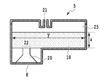
이어서, 헤드(5)의 액체 수납 유닛(25)의 형상에 대해서 설명한다. 도 5는 도 4에 도시되는 헤드(5)의 V-V 선을 따르는 단면도를 나타낸다.Next, the shape of the liquid containing
제1 실시형태의 헤드(5)에서, 참조 부호 z는 헤드(5)가 액체 토출 장치에 탑재된 자세에서의 유지 부재(18)의 높이 방향의 변의 길이를 나타내고, 참조 부호 y는 부주사 방향을 따르는 액체 수납 유닛(25)의 액체 수납 유닛의 내벽의 변의 길이를 나타낸다. 이때, y/z가 1.5 이상이 되도록 헤드(5)가 형성된다. 즉, 헤드(5)의 액체 수납 유닛(25)의 내부 공간이 직육면체 형상으로 형성된다. 헤드(5)가 캐리지(31)에 제공되는 자세에서, 헤드(5)는, 내부 공간의 수평면을 따른 단면의 긴 변의 길이를, 중력 방향을 따르는 유지 부재(18)의 길이로 나누어 얻은 값이 1.5 이상이 되도록 형성된다. 설계 이유를 고려할 때, y/z는 바람직하게 10 이하이다.In the
헤드(5)의 액체 수납 유닛(25) 및 유지 부재(18)가 이와 같이 형성되기 때문에, 액체 수납 유닛(25)의 수평면과 평행한 표면을 따르는 단면적이 넓어진다. 액체를 저장하는 액체 수납 유닛(25)은 단면적이 넓은 공간을 갖는다. 한편, 그 공간과 연통하는 액체 토출 유닛(8)을 향하는 유로는 좁은 단면적으로 형성된다. 따라서, 액체 수납 유닛(25) 로부터, 액체 토출 유닛(8)을 향하는 유로에서 액체가 유동하는 경우에, 높은 저항이 발생한다. 액체의 유동에 높은 저항이 발생하므로, 액체 수납 유닛(25)에 저장된 액체는 그로부터 유동하기가 어려워진다.Since the
또한, 헤드(5)의 액체 수납 유닛(25)의 내부에서는, 액체는 유지 부재(18)에 의해 유지된다. 따라서, 액체가 그로부터 유동하는 경우, 더 높은 저항이 액체에 가해진다. 액체의 이동에 더 높은 저항이 가해지므로, 헤드(5)에 충격이 가해지고 헤드(5)의 주사에 의한 관성력이 액체 수납 유닛(25) 내부의 액체에 가해지는 경우에도, 액체는 액체 수납 유닛(25) 내에 안정되게 수납된다.In addition, in the interior of the liquid containing
또한, 헤드(5)에서, 액체 토출 유닛(8)에 인접하는 액체 챔버(20)와 연통하는 유로 입구(22)에 대향하는 위치에 공급 포트(21)가 배치되어 있지 않다. 공급 포트(21)는, 액체 수납 유닛의 내부에 개구되고, 액체 수납 용기로부터 공급되는 액체의 액체 수납 유닛 내부로의 입구이다. 공급 포트(21)는, 액체 수납 유닛(25)의 내부 공간과 액체 챔버(20)가 서로 연통하는 유로 입구(22)의 형성 위치에 대향하는 위치로부터 오프셋된 위치에 있다. 그로 인해, 액체 수납 유닛에 공급되는 액체는, 액체가 액체 토출 유닛(8)에 공급될 때까지, 유지 부재(18)의 내부에서 수평 방향의 이동 결여가 없는 상태로(수평 방향의 성분을 가진 상태로) 이동하게 된다.The
액체가 유지 부재(18)의 내부를 수평 방향으로 이동하는 경우에는, 유지 부재(18)로부터 비교적 높은 저항을 받는다. 따라서, 그 부분을 통과하는 액체는 더 이동하기 어렵다. 따라서, 액체 수납 유닛의 내부에 일단 수납된 액체는 더 이동하기가 어렵다. 액체는 진동 등에 의해 영향을 받기 어렵고 보다 안정되게 수납된다.When the liquid moves in the horizontal direction inside the holding
유지 부재가 액체 수납 유닛에 배치되지 않고 액체가 액체 수납 유닛에 직접적으로 수납되는 경우에는, 액체 수납 유닛의 내부에 수납된 액체에 충격이나 주사에 의한 관성력이 가해지는 경우, 액면에 진동이 발생할 수 있다. 결과적으로, 액체 수납 유닛의 내부에 수납된 액체의 압력이 변동할 수 있고, 액체 수납 유닛의 내부에 수납된 액체의 압력의 규모가 불안정해질 수 있다. 그러나, 본 실시형태의 헤드(5)에서는, 액체 수납 유닛의 내부의 유지 부재(18)에 의해 액체가 유지되고, 따라서 요동에 의한 액체의 이동을 억제할 수 있다.In the case where the holding member is not disposed in the liquid containing unit but the liquid is directly housed in the liquid containing unit, when the liquid stored in the liquid containing unit is subjected to an impact or an inertial force due to injection, have. As a result, the pressure of the liquid contained in the liquid containing unit may fluctuate, and the scale of the pressure of the liquid stored in the liquid containing unit may become unstable. However, in the
이상으로부터, 액체 수납 유닛의 내부에 액체가 안정되게 수납되므로, 액체 수납 유닛으로부터 액체 토출 유닛에 액체를 안정되게 공급할 수 있다. 액체 토출 유닛에 액체가 안정되게 공급되므로, 액체 토출 유닛의 토출 포트로부터 액체를 안정되게 토출할 수 있다. 이에 의해, 액체 토출 유닛으로부터 액체를 정밀하게 토출하는 것이 가능하다. 그로 인해, 인쇄에 의해 얻어지는 인쇄 화상의 품질을 높게 유지할 수 있다.As described above, since the liquid is stably stored in the liquid containing unit, the liquid can be stably supplied from the liquid containing unit to the liquid discharge unit. The liquid is stably supplied to the liquid discharge unit, so that the liquid can be stably discharged from the discharge port of the liquid discharge unit. Thereby, it is possible to accurately discharge the liquid from the liquid discharge unit. As a result, the quality of the print image obtained by printing can be kept high.
또한, 액체 수납 유닛(25)의 내부에 저장된 액체는 그로부터 유동하는 것이 어렵다. 한편, 액체 수납 유닛(25)에 남아 있는 공기 기포는 그로부터 용이하게 유동한다. 따라서, 액체와 공기 기포 사이의 유동의 용이성의 차를 이용하여, 액체 토출 유닛(8) 및 액체 수납 유닛(25)으로부터 공기 기포를 용이하게 제거할 수 있다.Further, the liquid stored inside the
액체 수납 유닛(25)에 공기가 유입하여 공기 기포가 발생하는 경우에도, 액체 수납 유닛(25)의 내부에서의 액체 유동의 유동 저항이 높다. 따라서, 액체 토출 유닛(8)의 토출 포트를 통해 흡인이 행해지는 경우에, 액체의 양은 흡인의 정도를 추종하지 않고 따라서 공기 기포만이 효율적으로 제거된다. 또한, 액체 수납 유닛(25)의 내부의 부압은 용이하게 증가하기 때문에, 액체 수납 유닛(25)이 밀봉된 상태에서 토출 포트로부터 흡인이 행하여지는 초크 흡인(choke suction)과 마찬가지의 효과를 얻을 수 있다. 따라서, 간단한 구성에 의해 헤드(5)의 액체 수납 유닛(25)으로부터 공기 기포를 제거하기 때문에, 인쇄 장치의 소형화 및 저비용화를 실현할 수 있다.The flow resistance of the liquid flow inside the
공기 기포를 제거하기 위한 메커니즘으로서는, 헤드(5)의 액체 토출 유닛(8)의 토출 포트 주위의 영역을 캡으로 덮는다.As a mechanism for removing air bubbles, an area around the discharge port of the
먼저, 캡에 의해, 캡과 액체 토출 유닛(8) 사이의 공간이 밀봉된다. 그 상태에서, 캡에 흡인 펌프를 연결함으로써, 밀봉된 공간으로부터 흡인 펌프에 의해 공기를 흡인한다. 이에 의해, 캡과 액체 토출 유닛(8)에 의해 밀봉된 공간으로부터 잉크와 함께 액체 수납 유닛(25)의 내부에 남아 있는 공기 기포가 흡인되고, 결과적으로 액체 토출 유닛(8) 및 액체 수납 유닛(25)으로부터 공기 기포가 제거된다.First, the space between the cap and the
이 방법에 의하면, 액체 수납 용기(2)로부터 가요성 부재(3)를 통해 헤드(5)의 액체 수납 유닛(25)에 액체가 공급되고, 액체와 함께 있는 공기 기포가 액체 토출 유닛(8)의 토출 포트로부터 제거된다.According to this method, liquid is supplied from the
또한, 헤드(5)의 액체 수납 유닛(25)에서, 공급 포트(21)는, 액체 토출 유닛(8)과 연통하는 유로 입구(22)에 대향하는 바로 위의 위치에 배치되지 않는다. 공급 포트(21)가, 액체 토출 유닛(8)에 액체가 공급되는 유로 입구(22)에 대향하는 위치로부터 오프셋되어 형성된다. 그로 인해, 공기 기포의 제거를 위해서 액체 토출 유닛(8)의 토출 포트로부터 흡인을 행하는 경우에, 액체 토출 유닛(8)으로 유동하는 액체가 흡인에 의해 유지 부재(18)를 통과한다. 이 경우, 유지 부재(18)의 모관력에 의해 일정량의 액체가 액체 수납 유닛(25)에 저장된다.The
액체 토출 장치(1)가 장기에 걸쳐 사용되는 경우, 외기와의 습도 차로 인해 예를 들어 가요성 부재의 부분으로부터 액체 수납 유닛(25) 안으로 공기가 서서히 침입하고, 액체 수납 유닛(25)의 내부에 공기 기포가 발생한다. 그로 인해, 미리결정된 기간의 간격으로 공기를 배출하는 것이 필요하다. 그러나, 본 발명에 따르면, 잉크 공급 위치로부터 액체 챔버에의 유로 입구까지의 거리는 길고 액체를 유지하는 영역은 증가되며, 따라서 많은 양의 액체를 유지하게 된다.When the liquid ejection apparatus 1 is used over a long period of time, the difference in humidity with the outside air gradually enters the
또한, 액체 수납 유닛(25)의 내부에 저장된 액체에 의해 액체 토출 유닛(8)에 액체를 공급하기 위한 유동 저항이 증가되도록 구성된다. 공기 기포의 제거에 있어서, 많은 양의 액체의 흡인 없이 공기 기포만이 제거된다. 따라서, 공기 기포의 제거에 있어서 많은 양의 액체를 함께 흡인할 필요가 없다. 그로 인해, 흡인을 행할 때에 액체 흡인량을 적게 억제할 수 있다.Further, the flow resistance for supplying liquid to the
적은 액체의 흡인량에 의해 공기 기포가 충분하게 제거되기 때문에, 흡인 구동력을 감소시킬 수 있고, 흡인에 사용되는 펌프를 소형화할 수 있다. 따라서, 액체 토출 장치(1)를 소형화할 수 있고, 액체 토출 장치(1)의 제조 비용을 감소시킬 수 있다. 또한, 액체 수납 유닛(25)의 내부의 액체가 흡인되며, 이에 의해 액체 수납 유닛(25) 내부의 액체의 회복 동작을 행함에 있어서 회복 동작에 의한 액체의 흡인량이 감소된다. 결과적으로, 액체의 소비량이 감소될 수 있다.Since the air bubbles are sufficiently removed by the suction amount of a small amount of liquid, the suction driving force can be reduced, and the pump used for suction can be downsized. Therefore, the liquid discharge device 1 can be downsized, and the manufacturing cost of the liquid discharge device 1 can be reduced. In addition, the liquid inside the
또한, 적은 흡인에 의해 공기 기포를 충분히 흡인할 수 있다. 공기 기포가 확실하게 흡인되어 제거되므로, 흡인을 행하는 간격을 길게 연장시킬 수 있다. 그로 인해, 흡인을 행하는 빈도를 감소시킬 수 있고, 흡인 횟수를 감소시킬 수 있다. 따라서, 흡인에 의해 배출되는 액체의 양을 감소시킬 수 있고, 액체의 소비량을 더 감소시킬 수 있다. 액체의 소비량이 적어지기 때문에, 액체 토출 장치의 동작 비용을 감소시킬 수 있다.Further, air bubbles can be sufficiently sucked by a small suction. Air bubbles are reliably sucked and removed, so that the interval of suction can be prolonged. As a result, the frequency of performing suction can be reduced, and the number of suction times can be reduced. Therefore, the amount of liquid discharged by suction can be reduced, and the consumption amount of the liquid can be further reduced. The consumption amount of the liquid is reduced, so that the operation cost of the liquid discharge apparatus can be reduced.
(제2 실시형태)(Second Embodiment)
이어서, 본 발명의 제2 실시형태에 따른 헤드(52)에 대해서 설명한다. 제1 실시형태의 것과 마찬가지로 구성되는 부분에 대해서는 도면에서 동일한 부호를 붙여서 설명을 생략하고, 상이한 부분에 대해서만 설명한다는 것을 유의하라.Next, the
도 6은 제2 실시형태에 따른 헤드(52)의 단면도를 도시한다. 헤드(52)의 액체 수납 유닛(25)을 길이 방향(긴 변의 연장 방향)으로 3개의 영역으로 균등하게 분할하는 경우, 액체 챔버(20)로의 유로 입구(22)의 중심은 일 단부의 영역 내에 배치된다. 또한, 3개의 분할된 영역 중, 중앙부의 영역 내에 공급 포트(21)가 배치된다.Fig. 6 shows a cross-sectional view of the
제2 실시형태에 따르면, 공급 포트(21)를 유로 입구의 반대측 단부 영역에 배치하는 경우, 유지 부재(18) 내에서의 액체의 통과 거리가 길어진다. 이에 의해, 압력 손실이 지나치게 커지고, 액체의 토출이 불안정해질 수 있다. 이 경우에는, 도 6에 도시된 바와 같이, 공급 포트(21)와 유로 입구(22)는 길이 않은 거리로 배치되는 것이 바람직하다. 그로 인해, 본 실시형태에 따르면, 3개의 분할된 영역 중, 유로 입구(22)는 일 단부의 영역에 배치되고, 공급 포트(21)는 중앙부의 영역에 배치된다.According to the second embodiment, when the
(제3 실시형태)(Third Embodiment)
이어서, 본 발명의 제3 실시형태에 따른 헤드(53)에 대해서 설명한다. 제1 및 및 제2 실시형태의 것과 마찬가지로 구성되는 부분에 대해서는 도면 중 동일한 부호를 붙여서 설명을 생략하고, 상이한 부분에 대해서만 설명한다는 것을 유의하라.Next, the
도 7은, 본 발명의 제3 실시형태에 따른 헤드(53)에의 초기 잉크 주입 상태의 단면도를 도시한다. 잉크는 헤드(53)의 유지 부재(18)에 미리 부여되어, 이후의 액체 공급에 의해 액체를 안정되게 공급하게 되고, 액체는 액체 토출 유닛(8)으로부터 안정되게 토출된다. 이로 인해, 제조 과정의 헤드에의 액체의 주입 과정에서, 복수의 주입 니들이 유지 부재(18)에 삽입된 상태에서, 초기의 액체가 주입되어서 액체 수납 유닛(25)에 액체가 충전된다. 즉, 내부 공간으로부터 액체 토출 유닛(8)에 액체를 공급하는 액체 챔버(20)가 내부 공간과 연통하며, 유지 부재(18)에 삽입되는 액체 공급 니들(액체 공급 니들)이 삽입되는, 유로 입구(22)에 대응하는 위치에서 선단으로부터 내부 공간에 액체가 충전된다. 그리고, 액체 공급 니들을 통해 내부 공간에 액체가 충전된다.Fig. 7 shows a cross-sectional view of the initial ink injection state of the
유지 부재(18)의 모관력에 의해, 액체 주입 니들의 삽입 위치(24)를 정점으로 하여 액체의 분포가 서서히 확대되고, 결과적으로 액체가 볼록하게 주입된다. 제3 실시형태의 헤드(53)에서는, 액체 토출 유닛(8)의 유로가 되는 액체 챔버(20)의 유로 입구(22)에 대응하는 위치에 액체 주입 니들의 삽입 위치(24)가 배치되고, 액체 수납 유닛(25)에 액체가 충전된다. 따라서, 제3 실시형태의 액체 충전 방법에 의하면, 액체 토출 유닛(8)에 액체가 안정되게 공급될 수 있고, 액체 토출 유닛(8)으로부터 액체를 안정되게 토출할 수 있다.The distribution of the liquid is gradually enlarged with the
액체의 분포 형태의 정점이 공급 포트(21)의 바로 아래에 위치되는 경우, 상품의 유통 시에 공급 포트(21)로부터 액체가 누설될 수 있다. 그로 인해, 상품의 유통 시에 헤드가 더럽혀질 수 있다. 따라서, 액체 수납 유닛(25)에의 초기 액체 주입 위치(24)의 바로 위가 아닌 위치에 공급 포트(21)를 배치하는 것이 바람직하다.When the vertex of the distribution form of the liquid is located directly below the
(제4 실시형태)(Fourth Embodiment)
이어서, 본 발명의 제4 실시형태에 따른 헤드(54)에 대해서 설명한다. 제1 내지 제3 실시형태의 것과 마찬가지로 구성되는 부분에 대해서는 도면 중 동일 부호를 붙여서 설명을 생략하고, 상이한 부분에 대해서만 설명한다는 것을 유의하라.Next, the
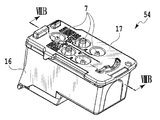
도 8a 내지 도 8c는 제4 실시형태의 헤드(54)를 나타낸다. 도 8a는 헤드(54)의 사시도이고, 도 8b는 도 8a의 헤드(54)의 VIIIB-VIIIB 선을 따르는 단면도이며, 도 8c는 도 8a의 액체 수납 유닛(25)을 상방으로부터 본 평면도이다. 도 8b에 도시된 바와 같이, 헤드(54)에서는, 액체 수납 유닛(25)이 복수의 공간으로 구획된다. 복수의 공간으로 구획된 액체 수납 유닛(25) 중, 그 일부에서, 공급 포트(21)는 액체 수납 유닛(25)에의 유로 입구(22)의 바로 위에 배치되지 않을 수 있다.8A to 8C show the
(제5 실시형태)(Fifth Embodiment)
이어서, 본 발명의 제5 실시형태에 따른 헤드(55a, 55b)에 대해서 설명한다. 상기 제1 내지 제4 실시형태의 것과 마찬가지로 구성되는 부분에 대해서는 도면 중 동일 부호를 붙여서 설명을 생략하고, 상이한 부분에 대해서만 설명한다는 것을 유의하라.Next, the
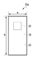
도 9a는, 1개의 헤드에 1개의 액체 수납 유닛이 형성되어 있는 경우에, 커버 부재 측으로부터 본 액체 수납 유닛(25)을 갖는 제5 실시형태에 따른 헤드(55a)의 평면도를 나타낸다. 도 9b는, 액체 수납 유닛(25)이 1개의 헤드에 형성되는 복수의 공간으로 구획된 경우의, 헤드(55b)를 커버 부재 측으로부터 본 제5 실시형태에 따른 헤드(55b)의 평면도를 나타낸다.9A is a plan view of the
헤드(55a)는 실질적으로 직육면체 형상으로 형성된다. 헤드(55a)는, 수평면과 평행한 평면을 따르는 단면이 직사각형으로 되어 있는 직육면체 형상을 갖는다. 여기에서는, 참조 부호 a는 짧은 변의 길이를 나타내며, 참조 부호 b는 긴 변의 길이를 나타낸다. 이때, b/a는 2.0 이상이다.The
또한, 분할된 복수의 액체 수납 유닛(25) 각각은 헤드(55b)에서 실질적으로 직육면체 형상으로 형성된다. 도 9b의 헤드(55b)는 3개의 액체 수납 유닛(25)으로 분할된다. 3개의 분할된 액체 수납 유닛(25) 중 2개에서, 참조 부호 a는 짧은 변의 길이를 나타내며, 참조 부호 b는 긴 변의 길이를 나타내고, b/a는 2.0 이상이다. 또한, 제5 실시형태의 헤드(55a, 55b)에서는, 대응하는 액체 수납 유닛(25)에서의 내부 공간의 수평면을 따른 단면의 긴 변(b)은, 캐리지(31)의 왕복 이동의 이동 방향에 교차하는 방향으로 연장되는 변이다.Each of the divided
헤드(55a, 55b)에서의 액체 수납 유닛(25)의 형상에 따라, 공급 포트(21)로부터 액체 챔버(20)를 향하는 유로 입구(22)까지의 거리가 충분하지 않고, 유지 부재(18)에 의한 압력 손실이 불충분할 수 있다. 그로 인해, 액체 수납 유닛(25)에 저장된 액체의 저항이 부족하고, 저장된 잉크가 불안정할 수 있다.The distance from the
그로 인해, 본 실시형태의 헤드(55a, 55b)에서는, 유지 부재(18)에 의한 압력 손실을 충분히 확보하기 위해서, 긴 변(b)의 길이를 짧은 변(a)의 길이에 비해 길게 형성한다. 결과적으로, 공급 포트(21)로부터 유로 입구(22)까지의 길이는 충분히 길게 확보될 수 있다. 공급 포트(21)와 유로 입구(22)의 구성에 따라, 유지 부재(18)를 통과하는 액체의 압력 손실은 충분히 확보될 수 있다. 설계 이유를 고려할 때, b/a는 바람직하게 10 이하이다.Therefore, in the
(제6 실시형태)(Sixth Embodiment)
이어서, 본 발명의 제6 실시형태에 따른 헤드(56)에 대해서 설명한다. 상기 제1 내지 제5 실시형태의 것과 마찬가지로 구성되는 부분에 대해서는 도면 중 동일한 부호를 붙여서 설명을 생략하고, 상이한 부분에 대해서만 설명한다는 것을 유의하라.Next, the
도 10은 제6 실시형태의 헤드의 단면도이다. 제1 내지 제5 실시형태에 따르면, 액체 수납 용기(2)로부터 가요성 부재(3)를 통해 액체 수납 유닛(25)에 공급되는 액체는 커버 부재(17)에 형성된 공급 포트(21)를 통해서 공급된다. 한편, 제6 실시형태의 헤드(56)에서는, 유지 부재(18)에 도달하는 액체 공급 니들(30)이 커버 부재(17)에 부착된다. 액체 공급 니들(30)이 유지 부재(18)에 삽입된 상태에서, 액체 공급 니들(30)을 통해 액체 수납 용기(2)로부터 헤드(56)의 액체 수납 유닛(25)의 내부에 액체가 공급된다.10 is a sectional view of the head of the sixth embodiment. The liquid supplied from the
위에서 언급된 바와 같이, 헤드(56)에의 액체의 초기 충전뿐만 아니라, 인쇄 중에서의 액체 수납 용기(2)로부터 헤드(56)의 액체 수납 유닛(25)에의 액체의 공급에서도, 액체 공급 니들(30)이 사용될 수 있다.As described above, not only the initial filling of the liquid into the
또한, 액체는 공급 포트(21)로부터 유지 부재(18) 내에 액체 공급 니들(30)을 삽입함으로써 연속적으로 공급될 수 있다. 즉, 액체는, 가요성 부재(3)와 액체 수납 유닛(25)의 내부 공간이 서로 연통하며, 유지 부재(18)에 삽입될 수 있는 액체 공급 니들이 삽입되는, 공급 포트(21)의 선단으로부터 내부 공간에 충전된다. 그로부터, 액체는 액체 공급 니들을 통해 내부 공간에 충전된다. 이 경우, 공급 포트(21)가 액체 챔버(20)에의 유로 입구(22)에 대향하는 유로 입구(22) 바로 위의 위치로부터 오프셋된 위치에 배치되는 경우, 액체 공급 니들(30)로부터의 액체 공급에서도 유지 부재(18)로부터 원하는 압력 손실이 얻어진다.In addition, the liquid can be continuously supplied by inserting the liquid supply needles 30 into the holding
(제7 실시형태)(Seventh Embodiment)
이어서, 본 발명의 제7 실시형태에 따른 헤드에 대해서 설명한다. 제1 내지 제6 실시형태의 것과 마찬가지로 구성되는 부분에 대해서는 도면 중 동일한 부호를 붙여서 설명을 생략하고, 상이한 부분에 대해서만 설명한다는 것을 유의하라.Next, a head according to a seventh embodiment of the present invention will be described. It should be noted that the same constituent elements as those of the first to sixth embodiments are denoted by the same reference numerals in the drawings and the description thereof is omitted, and only the different parts are described.
제7 실시형태의 헤드에서는, 유지 부재(18)를 형성하는 재료로서, 폴리올레핀계 수지로 형성된 섬유가 사용된다. 폴리올레핀계 수지로 형성된 섬유의 얽힘에 의해 유지 부재(18)가 형성된다.In the head of the seventh embodiment, as the material for forming the holding
유지 부재(18)의 모관력에 의해 액체를 유지하도록 구성된다. 유지 부재(18)를 형성하는 재료의 모관력이 극단적으로 작은 경우에는, 액체 수납 유닛(25) 내부에서의 압력 손실이 낮다. 그로 인해, 헤드에서는, 가요성 부재에 의한 잉크 공급이나 헤드의 주사에 의해 유발되는 액체의 액면 요동에 의해, 액체 수납 유닛(25) 내부에서의 압력 변화가 증가된다. 이에 의해, 액체 토출 유닛(8)로부터의 액체가 불안정하게 토출될 수 있다. 또한, 유지 부재(18)의 모관력이 극단적으로 높은 경우에는, 유지 부재(18)에 의한 압력 손실이 너무 높아서 액체는 액체 수납 유닛(25)으로부터 액체 토출 유닛(8)에 불안정되게 공급될 수 있다. 이로 인해, 유지 부재(18)의 모관력은 적절한 수준으로 조절되는 것이 바람직하다.And is configured to hold the liquid by the capillary force of the holding member (18). The pressure loss inside the
유지 부재(18)가 헤드에 보다 적합한 압력 손실을 발생시키는 부재로서 기능하기 위해서는, 유지 부재(18)를 형성하는 섬유는 도 11에 도시된 바와 같이 서로 무작위적으로 복수 교차하는 것이 바람직하다. 즉, 섬유가 액체와 접촉했을 경우에는, 도 11에 도시된 바와 같이 액체의 표면 장력에 의해, 각 섬유를 화살표 방향으로 이동시키는 힘이 작용한다. 그러나, 복수의 교차에 의해 그 힘이 상쇄된다. 그로 인해, 유지 부재(18)를 형성하는 섬유의 수축을 억제할 수 있다.In order for the retaining
도 12a 및 도 12b는, 유지 부재(18)를 형성하는, 상이한 종류의 재료로 형성된 복수의 층을 구비한 섬유의 개략적인 단면도를 도시한다. 도 12a 및 도 12b에 도시된 바와 같이, 유지 부재(18)를 형성하는 섬유 내에는 용융 온도가 높은 재료로 형성된 핵부(B)가 형성된다. 또한, 핵부(B)의 외측에는, 핵부(B)의 용융 온도보다 낮은 용융 온도를 갖는 표층(A)이 형성된다. 상술한 바와 같이, 표층(A)과 핵부(B)를 포함하는 섬유가 도 11에 도시된 바와 같이 서로 얽힌 상태로 형성된다.Figures 12A and 12B show schematic cross-sectional views of fibers having a plurality of layers formed of different types of materials, forming a retaining
이어서, 섬유의 표층(A)과 관련하여, 그 섬유는 용융된 표층(A)의 수지 온도 이상으로 가열된다. 섬유의 핵부(B)와 관련하여, 그 섬유는 용융된 핵부(B)의 수지 온도 이하로 가열된다. 가열에 의해, 표층(A)만이 용융된 상태에서 섬유가 얽힌다. 이에 의해, 표층(A)만이 용융된 상태에서 복수 교차 결과로서의 교점이 서로 접촉한다. 용융 상태에서 접촉된 표층(A)이 응고되는 경우, 접촉된 섬유는 용융된다. 섬유가 얽힌 상태에서, 섬유의 교점이 용융되어 부착되고, 그 섬유 전체가 응고된다. 이때 얽히는 정도를 조절함으로써 유지 부재(18)에 의한 모관력을 조절하는 것도 바람직한 수단이다.Then, with respect to the surface layer (A) of the fibers, the fibers are heated to a temperature not lower than the resin temperature of the molten surface layer (A). Regarding the core part (B) of the fiber, the fiber is heated to a temperature not higher than the resin temperature of the molten core part (B). By heating, only the surface layer (A) is entangled with fibers in a molten state. As a result, in the state where only the surface layer (A) is melted, the intersections as a plurality of crossing results come into contact with each other. When the surface layer (A) brought into contact in the molten state is solidified, the contacted fibers are melted. In the state where the fibers are entangled, an intersection of the fibers is melted and attached, and the entire fiber is solidified. At this time, it is also a preferable means to adjust the traction force by the holding
본 발명을 예시적인 실시형태를 참고하여 설명하였지만, 본 발명은 개시된 예시적인 실시형태로 한정되지 않음을 이해해야 한다. 이하의 청구항의 범위는 이러한 모든 변형 및 동등한 구조 및 기능을 포함하도록 최광의로 해석되어야 한다.While the present invention has been described with reference to exemplary embodiments, it is to be understood that the invention is not limited to the disclosed exemplary embodiments. The scope of the following claims is to be accorded the broadest interpretation so as to encompass all such modifications and equivalent structures and functions.
Claims (9)
내부에 액체를 저장할 수 있는 액체 수납 용기와,
캐리지 상에 제공되며, 내부에 액체를 유지할 수 있는 유지 부재를 갖는 액체 수납 유닛과 액체를 토출하는 액체 토출 유닛을 포함하는 헤드와,
상기 액체 수납 용기를 상기 액체 수납 유닛에 연결하며, 상기 액체 수납 용기의 내부에 저장된 액체를 상기 액체 수납 유닛에 공급하는 가요성 부재를 포함하며,
상기 액체 수납 유닛의 내부 공간은 직육면체 형상을 갖고,
상기 헤드가 상기 캐리지 상에 제공된 자세에서, 상기 내부 공간에서의 수평면을 따른 단면의 긴 변의 길이를 상기 유지 부재의 중력 방향을 따르는 길이로 나누어 얻은 값이 1.5 이상 10 이하인, 액체 토출 장치.A liquid ejecting apparatus comprising:
A liquid storage container capable of storing a liquid therein,
A head provided on the carriage and including a liquid containing unit having a holding member capable of holding a liquid therein and a liquid discharge unit for discharging liquid,
And a flexible member that connects the liquid containing container to the liquid containing unit and supplies the liquid stored in the liquid containing container to the liquid containing unit,
Wherein the internal space of the liquid containing unit has a rectangular parallelepiped shape,
Wherein a value obtained by dividing a length of a long side of a cross section along a horizontal plane in the internal space by a length along the gravity direction of the holding member in an attitude provided on the carriage is 1.5 to 10.
상기 액체 수납 유닛의 내부에 개구되고 상기 액체 수납 용기로부터 공급되는 액체의 상기 액체 수납 유닛의 내부에의 입구인 공급 포트는, 상기 액체 수납 유닛의 상기 내부 공간으로부터 상기 액체 토출 유닛에 액체를 공급하는 액체 유로와 상기 내부 공간이 연통하는 유로 입구가 형성된 위치에 대향하는 위치로부터 오프셋된 위치에 형성되어 있는, 액체 토출 장치.The method according to claim 1,
Wherein the supply port which is opened at the inside of the liquid containing unit and is an inlet to the inside of the liquid containing unit of the liquid supplied from the liquid containing container supplies the liquid from the internal space of the liquid containing unit to the liquid discharge unit Wherein the liquid passage is formed at a position offset from a position opposed to a position where the liquid passage and a passage entrance communicating with the internal space are formed.
상기 액체 수납 유닛의 상기 내부 공간이 상기 긴 변의 연장 방향으로 3개의 영역으로 균등하게 분할되는 경우에,
상기 유로 입구는 상기 3개의 영역 중 상기 긴 변의 연장 방향을 따르는 일 단부의 영역에 형성되며,
상기 공급 포트는 상기 3개의 영역 중 상기 긴 변의 연장 방향을 따르는 중앙 영역에 형성되어 있는, 액체 토출 장치.3. The method of claim 2,
When the internal space of the liquid containing unit is evenly divided into three regions in the extending direction of the long sides,
Wherein the flow passage inlet is formed in a region of one end of the three regions along the extending direction of the long side,
Wherein the supply port is formed in a central region along the extending direction of the long side among the three regions.
상기 캐리지는 왕복할 수 있도록 구성되며,
상기 내부 공간에서의 수평면을 따른 단면의 상기 긴 변은, 상기 캐리지의 왕복 이동의 이동 방향과 교차하는 방향으로 연장하는 변인, 액체 토출 장치.The method according to claim 1,
The carriage is configured to reciprocate,
Wherein the long side of the cross section along the horizontal plane in the internal space is a direction extending in a direction intersecting with the moving direction of reciprocating movement of the carriage.
상기 헤드가 상기 캐리지 상에 제공된 자세에서, 상기 내부 공간에서의 수평면을 따른 단면의 긴 변의 길이를 상기 내부 공간에서의 수평면을 따른 단면의 짧은 변의 길이로 나누어 구한 값이 2.0 이상 10 이하인, 액체 토출 장치.The method according to claim 1,
Wherein a value obtained by dividing the length of the long side of the cross section along the horizontal plane in the internal space by the length of the short side of the cross section along the horizontal plane in the internal space in the posture in which the head is provided on the carriage is 2.0 or more and 10 or less, Device.
상기 유지 부재는 폴리올레핀계 수지의 섬유로 형성되는, 액체 토출 장치.The method according to claim 1,
Wherein the holding member is formed of fibers of a polyolefin-based resin.
상기 헤드는 내부에 액체를 저장할 수 있는 액체 수납 용기에 가요성 부재를 통해 연결되고,
상기 액체 수납 용기의 내부에 저장된 액체는 상기 가요성 부재를 통해서 상기 액체 수납 유닛의 내부에 공급되고,
액체를 유지할 수 있는 유지 부재가 상기 액체 수납 유닛의 내부에 배치되고,
상기 액체 수납 유닛의 내부 공간이 직육면체 형상으로 형성되며,
상기 캐리지 상에 제공된 자세에서, 상기 내부 공간에서의 수평면을 따른 단면의 긴 변의 길이를 상기 유지 부재의 중력 방향을 따르는 길이로 나누어 구한 값이 1.5 이상 10 이하인, 헤드.A head which can be provided on a carriage and includes a liquid containing unit capable of storing a liquid therein and a liquid discharge unit for discharging liquid,
The head is connected to a liquid containing container capable of storing liquid therein via a flexible member,
Liquid stored in the liquid containing container is supplied into the liquid containing unit through the flexible member,
A holding member capable of holding the liquid is disposed inside the liquid containing unit,
Wherein an inner space of the liquid containing unit is formed in a rectangular parallelepiped shape,
Wherein a value obtained by dividing the length of the long side of the cross section along the horizontal plane in the internal space by the length along the gravity direction of the holding member in the attitude provided on the carriage is 1.5 to 10.
상기 액체 수납 유닛의 내부로 개구되고 상기 액체 수납 용기로부터 공급되는 액체의 상기 액체 수납 유닛의 내부에의 입구인 공급 포트의 선단으로부터 상기 내부 공간에 액체를 충전하는 단계와,
상기 유지 부재에 삽입될 수 있는 액체 공급 니들을 삽입하는 단계와,
상기 액체 공급 니들을 통해 상기 내부 공간에 액체를 충전하는 단계를 포함하는, 액체 충전 방법.A liquid filling method for filling a liquid inside a liquid containing unit capable of being provided on a carriage and capable of storing a liquid therein, characterized in that the liquid containing unit includes a liquid containing container And a liquid stored in the liquid containing container is supplied to the inside of the liquid containing unit through the flexible member, a holding member capable of holding the liquid is disposed inside the liquid containing unit, Wherein the internal space of the unit is formed in a rectangular parallelepiped shape and the value obtained by dividing the length of the long side of the cross section along the horizontal plane in the internal space by the length along the gravity direction of the holding member is 1.5 to 10 Or less,
Filling liquid into the internal space from the tip of a supply port which is opened to the inside of the liquid containing unit and is an inlet to the inside of the liquid containing unit of the liquid supplied from the liquid containing container,
Inserting a liquid supply needle which can be inserted into the holding member,
And filling the internal space with liquid through the liquid supply needle.
액체 공급 니들의 선단으로부터 상기 내부 공간에 액체를 충전하며 상기 유지 부재에 삽입될 수 있는 상기 액체 공급 니들을, 상기 내부 공간에 저장된 액체를 토출할 수 있는 액체 토출 유닛에 액체를 공급하는 액체 유로가 상기 내부 공간과 연통하는 유로 입구에 대응하는 위치에 삽입하는 단계와,
상기 액체 공급 니들을 통해 상기 내부 공간에 액체를 충전하는 단계를 포함하는, 액체 충전 방법.A liquid filling method for filling a liquid inside a liquid containing unit capable of being provided on a carriage and capable of storing liquid therein, wherein the liquid containing unit is connected to a liquid container capable of storing liquid therein via a flexible member , A liquid stored in the liquid containing container is supplied to the inside of the liquid containing unit through the flexible member, a holding member capable of holding the liquid is disposed inside the liquid containing unit, Wherein the inner space is formed in a rectangular parallelepiped shape and a value obtained by dividing the length of the long side of the cross section along the horizontal plane in the inner space by the length along the gravity direction of the holding member in the attitude provided on the carriage is 1.5 to 10, A liquid filling method comprising:
The liquid supply needle which fills the internal space with the liquid from the tip of the liquid supply needle and can be inserted into the holding member and a liquid flow path for supplying the liquid to the liquid discharge unit capable of discharging the liquid stored in the internal space And inserting the gasket at a position corresponding to a flow passage opening communicating with the internal space;
And filling the internal space with liquid through the liquid supply needle.
Applications Claiming Priority (2)
| Application Number | Priority Date | Filing Date | Title |
|---|---|---|---|
| JP2015214265A JP2017081083A (en) | 2015-10-30 | 2015-10-30 | Liquid discharge device, head and liquid filling method |
| JPJP-P-2015-214265 | 2015-10-30 |
Publications (1)
| Publication Number | Publication Date |
|---|---|
| KR20170051279A true KR20170051279A (en) | 2017-05-11 |
Family
ID=58638178
Family Applications (1)
| Application Number | Title | Priority Date | Filing Date |
|---|---|---|---|
| KR1020160137766A KR20170051279A (en) | 2015-10-30 | 2016-10-21 | Liquid ejecting device, head, and liquid filling method |
Country Status (4)
| Country | Link |
|---|---|
| US (1) | US9962945B2 (en) |
| JP (1) | JP2017081083A (en) |
| KR (1) | KR20170051279A (en) |
| CN (1) | CN106626771B (en) |
Families Citing this family (14)
| Publication number | Priority date | Publication date | Assignee | Title |
|---|---|---|---|---|
| JP6308989B2 (en) | 2015-09-30 | 2018-04-11 | キヤノン株式会社 | Liquid storage container and liquid discharge device |
| JP6498098B2 (en) | 2015-10-30 | 2019-04-10 | キヤノン株式会社 | Recording apparatus and liquid storage member |
| JP6723729B2 (en) | 2015-11-17 | 2020-07-15 | キヤノン株式会社 | Liquid storage container and method of manufacturing liquid storage container |
| JP7267708B2 (en) | 2017-10-13 | 2023-05-02 | キヤノン株式会社 | MEMBER HAVING PAD ELECTRODE, INK CARTRIDGE, RECORDING DEVICE |
| CN111194266B (en) | 2017-10-13 | 2021-12-24 | 佳能株式会社 | Member including pad electrode, ink cartridge, and recording apparatus |
| JP7130404B2 (en) * | 2018-03-29 | 2022-09-05 | キヤノン株式会社 | Recording head and recording device |
| US10814637B2 (en) | 2018-03-29 | 2020-10-27 | Canon Kabushiki Kaisha | Print head and printing apparatus |
| JP7110038B2 (en) | 2018-09-06 | 2022-08-01 | キヤノン株式会社 | Liquid storage container and liquid ejection device |
| JP7242231B2 (en) | 2018-09-28 | 2023-03-20 | キヤノン株式会社 | Member having pad electrode, recording device |
| JP7224830B2 (en) | 2018-09-28 | 2023-02-20 | キヤノン株式会社 | MEMBER HAVING PAD ELECTRODE, INK CARTRIDGE, RECORDING DEVICE |
| JP7154919B2 (en) | 2018-09-28 | 2022-10-18 | キヤノン株式会社 | ink cartridge |
| JP7246978B2 (en) | 2019-03-15 | 2023-03-28 | キヤノン株式会社 | Liquid ejection device and liquid filling method |
| JP7391637B2 (en) | 2019-12-03 | 2023-12-05 | キヤノン株式会社 | Liquid storage device and liquid filling method |
| JP2021183400A (en) | 2020-05-22 | 2021-12-02 | キヤノン株式会社 | Liquid cartridge and liquid discharge device |
Family Cites Families (100)
| Publication number | Priority date | Publication date | Assignee | Title |
|---|---|---|---|---|
| US5430471A (en) | 1991-08-30 | 1995-07-04 | Canon Kabushiki Kaisha | Liquid container, recording head using same and recording apparatus using same |
| JP2960235B2 (en) | 1991-11-12 | 1999-10-06 | キヤノン株式会社 | INK CONTAINER, PRINT HEAD UNIT USING THE SAME, AND PRINTING APPARATUS MOUNTING THE SAME |
| JP3105047B2 (en) | 1991-11-18 | 2000-10-30 | キヤノン株式会社 | INK CONTAINER, PRINT HEAD UNIT USING THE SAME, AND PRINTING APPARATUS MOUNTING THE SAME |
| JPH05318756A (en) | 1992-05-22 | 1993-12-03 | Canon Inc | Ink container |
| JPH0615834A (en) | 1992-06-30 | 1994-01-25 | Canon Inc | Container, recording head device using this container and recording apparatus loaded with this container |
| CA2272165C (en) | 1992-07-31 | 2003-10-14 | Canon Kabushiki Kaisha | Liquid storing container for recording apparatus |
| US6170939B1 (en) | 1992-07-31 | 2001-01-09 | Canon Kabushiki Kaisha | Liquid storing container for recording apparatus |
| JP3253153B2 (en) | 1992-10-20 | 2002-02-04 | キヤノン株式会社 | Ink jet head cartridge and ink jet apparatus provided with the cartridge |
| JP3143539B2 (en) | 1993-02-03 | 2001-03-07 | キヤノン株式会社 | Ink remaining amount detecting method and apparatus, and ink jet recording apparatus |
| US6206514B1 (en) * | 1993-06-29 | 2001-03-27 | Canon Kabushiki Kaisha | Ink tank unit, an ink jet cartridge having said ink tank unit and an ink jet apparatus having said ink jet cartridge |
| DE69331791T2 (en) | 1993-07-20 | 2002-10-10 | Canon Kk | An ink jet recording apparatus which uses a color cartridge with an ink inducing element |
| JP3183760B2 (en) | 1993-10-04 | 2001-07-09 | キヤノン株式会社 | Ink container, inkjet recording head, inkjet cartridge, and inkjet recording apparatus |
| US5619239A (en) | 1993-11-29 | 1997-04-08 | Canon Kabushiki Kaisha | Replaceable ink tank |
| JP3101482B2 (en) | 1994-01-31 | 2000-10-23 | キヤノン株式会社 | Method and apparatus for manufacturing liquid holding container |
| JP3227296B2 (en) * | 1994-01-31 | 2001-11-12 | キヤノン株式会社 | Ink tank |
| US5751300A (en) * | 1994-02-04 | 1998-05-12 | Hewlett-Packard Company | Ink delivery system for a printer |
| DE69512578T2 (en) | 1994-07-28 | 2000-05-04 | Canon Kk | Ink-jet recording device, cleaning method and information processing system therefor |
| DE69535881D1 (en) | 1994-08-24 | 2008-12-11 | Canon Kk | Ink tank for inkjet printers |
| JP3274046B2 (en) | 1994-08-24 | 2002-04-15 | キヤノン株式会社 | Ink tank |
| US6116722A (en) | 1994-08-31 | 2000-09-12 | Canon Kabushiki Kaisha | Ink jet ink refilling method and apparatus |
| US5742310A (en) | 1995-02-28 | 1998-04-21 | Canon Kabushiki Kaisha | Ink jet printer and an ink storing member mounted on the printer |
| US5936650A (en) * | 1995-05-24 | 1999-08-10 | Hewlett Packard Company | Ink delivery system for ink-jet pens |
| JP3365215B2 (en) * | 1996-08-21 | 2003-01-08 | セイコーエプソン株式会社 | Printer ink cartridge device |
| JP3295339B2 (en) | 1996-08-30 | 2002-06-24 | キヤノン株式会社 | Ink tank, holder, inkjet cartridge and cap |
| JP3363052B2 (en) * | 1997-03-12 | 2003-01-07 | コピア株式会社 | Ink supply device and ink filling method |
| JP3332795B2 (en) | 1997-04-28 | 2002-10-07 | キヤノン株式会社 | Ink tank and inkjet cartridge |
| JPH1161637A (en) | 1997-08-18 | 1999-03-05 | Canon Inc | Fiber material and its use as ink-contacting member and production thereof |
| JPH11348261A (en) | 1998-06-10 | 1999-12-21 | Canon Inc | Method and apparatus for inspecting liquid ejection state of liquid ejection recording head |
| JP3437491B2 (en) | 1998-06-30 | 2003-08-18 | キヤノン株式会社 | INK INJECTION METHOD, INK INJECTION DEVICE USING THE SAME, AND INK JET RECORDING APPARATUS COMPRISING THE SAME |
| US6390612B1 (en) | 1999-08-30 | 2002-05-21 | Canon Kabushiki Kaisha | Method for filling ink holding member with ink, ink filling apparatus, and ink tank to be filled with ink by ink filling method |
| JP2001063089A (en) | 1999-08-30 | 2001-03-13 | Canon Inc | Ink tank, recording head cartridge and ink-jet recording apparatus |
| JP3733266B2 (en) | 1999-10-04 | 2006-01-11 | キヤノン株式会社 | Liquid storage container |
| DE60026423T2 (en) * | 1999-10-29 | 2006-11-16 | Seiko Epson Corp. | Ink cartridge for use in an ink jet recording apparatus |
| JP4282043B2 (en) * | 1999-12-06 | 2009-06-17 | キヤノン株式会社 | Recording liquid supply passage, recording liquid storage container, recording liquid supply apparatus including these, and surface modification method thereof |
| JP3392096B2 (en) * | 2000-02-22 | 2003-03-31 | キヤノン株式会社 | Ink tank and manufacturing method thereof |
| JP4789315B2 (en) | 2000-10-04 | 2011-10-12 | キヤノン株式会社 | Ink tank module and inkjet recording apparatus |
| JP3697213B2 (en) | 2001-02-09 | 2005-09-21 | キヤノン株式会社 | Liquid storage container and liquid stirring method |
| CA2371040A1 (en) | 2001-02-09 | 2002-08-09 | Nobuyuki Hatasa | Liquid container and recording apparatus |
| JP3796439B2 (en) | 2001-02-09 | 2006-07-12 | キヤノン株式会社 | Liquid storage container |
| JP3833123B2 (en) * | 2001-02-23 | 2006-10-11 | キヤノン株式会社 | Inkjet head stored and method for storing inkjet head |
| US6457821B1 (en) * | 2001-03-13 | 2002-10-01 | Hewlett-Packard Company | Filter carrier for protecting a filter from being blocked by air bubbles in an inkjet printhead |
| JP3667296B2 (en) | 2001-05-10 | 2005-07-06 | キヤノン株式会社 | Ink tank |
| JP3774675B2 (en) | 2001-05-10 | 2006-05-17 | キヤノン株式会社 | package |
| JP3667295B2 (en) | 2001-05-10 | 2005-07-06 | キヤノン株式会社 | Ink tank |
| JP3809401B2 (en) | 2001-07-27 | 2006-08-16 | キヤノン株式会社 | Ink tank |
| TW558512B (en) * | 2001-09-19 | 2003-10-21 | Seiko Epson Corp | Ink cartridge and its manufacturing method |
| KR100438702B1 (en) * | 2001-09-27 | 2004-07-05 | 삼성전자주식회사 | Ink cartridge |
| JP4250433B2 (en) | 2002-03-18 | 2009-04-08 | キヤノン株式会社 | Packaging structure of liquid container and method for opening the same |
| JP3919567B2 (en) | 2002-03-18 | 2007-05-30 | キヤノン株式会社 | Packaging structure of liquid container and method for opening the same |
| JP4018422B2 (en) | 2002-03-29 | 2007-12-05 | キヤノン株式会社 | Liquid container and method for identifying liquid container |
| TWI259149B (en) | 2002-09-30 | 2006-08-01 | Canon Kk | Ink container and recording apparatus |
| KR100723563B1 (en) * | 2002-09-30 | 2007-06-04 | 캐논 가부시끼가이샤 | Liquid supply system, ink tank, ink supply system, and inkjet recording apparatus |
| US6942326B2 (en) | 2002-09-30 | 2005-09-13 | Canon Kabushiki Kaisha | Ink tank |
| US7134747B2 (en) | 2002-09-30 | 2006-11-14 | Canon Kabushiki Kaisha | Ink container, recording head and recording device using same |
| JP2004174944A (en) | 2002-11-27 | 2004-06-24 | Canon Inc | Liquid housing container |
| JP2004237723A (en) * | 2003-01-17 | 2004-08-26 | Canon Inc | Ink jet recording device, imaging device, and ink supply method therein |
| JP2004230704A (en) | 2003-01-30 | 2004-08-19 | Canon Inc | Liquid tank |
| JP4200784B2 (en) | 2003-02-19 | 2008-12-24 | セイコーエプソン株式会社 | Liquid ejector |
| JP2004314600A (en) | 2003-04-04 | 2004-11-11 | Canon Inc | Liquid storing container, liquid using device and recording device, and ink jet cartridge |
| JP2004314602A (en) | 2003-04-04 | 2004-11-11 | Canon Inc | Liquid receptacle and manufacturing method thereof |
| JP3848298B2 (en) | 2003-05-22 | 2006-11-22 | キヤノン株式会社 | Ink tank |
| JP2004358913A (en) | 2003-06-06 | 2004-12-24 | Canon Inc | Ink tank and ink tank holder |
| JP2004358914A (en) | 2003-06-06 | 2004-12-24 | Canon Inc | Ink tank |
| JP2005028779A (en) | 2003-07-07 | 2005-02-03 | Canon Inc | Ink tank and ink tank holder |
| US6984029B2 (en) * | 2003-07-11 | 2006-01-10 | Hewlett-Packard Development Company, Lp. | Print cartridge temperature control |
| JP4484664B2 (en) | 2003-11-27 | 2010-06-16 | キヤノン株式会社 | Recording head cartridge |
| JP4289998B2 (en) * | 2003-12-26 | 2009-07-01 | キヤノン株式会社 | Inkjet recording cartridge |
| JP4058434B2 (en) | 2003-12-26 | 2008-03-12 | キヤノン株式会社 | Ink storage container, method for manufacturing the same, and printer system |
| US7399070B2 (en) * | 2004-03-09 | 2008-07-15 | Brother Kogyo Kabushiki Kaisha | Ink jet printer |
| JP2005288929A (en) * | 2004-04-01 | 2005-10-20 | Canon Inc | Ink-jet recording head |
| JP4115465B2 (en) | 2004-06-02 | 2008-07-09 | キヤノン株式会社 | Ink jet recording head, ink jet cartridge including ink jet recording head, and ink jet recording apparatus |
| US7396118B2 (en) | 2004-07-09 | 2008-07-08 | Canon Kabushiki Kaisha | Cartridge for ink jet recording and method for producing the same |
| JP4533125B2 (en) | 2004-10-20 | 2010-09-01 | キヤノン株式会社 | Ink tank and ink jet recording apparatus |
| US7384116B2 (en) | 2004-10-20 | 2008-06-10 | Canon Kabushiki Kaisha | Liquid container and ink jet printing apparatus |
| US7296881B2 (en) * | 2005-01-21 | 2007-11-20 | Hewlett-Packard Development Company, L.P. | Printhead de-priming |
| US7722173B2 (en) * | 2005-09-29 | 2010-05-25 | Hewlett-Packard Development Company, L.P. | Fluid container having a fluid absorbing material |
| US9352573B1 (en) * | 2006-01-30 | 2016-05-31 | Shahar Turgeman | Ink printing system comprising groups of inks, each group having a unique inkbase composition |
| US8313185B2 (en) | 2006-03-31 | 2012-11-20 | Canon Kabushiki Kaisha | Liquid container and liquid container package |
| JP4926538B2 (en) | 2006-05-11 | 2012-05-09 | キヤノン株式会社 | Liquid storage container and recording apparatus |
| JP4164519B2 (en) | 2006-06-16 | 2008-10-15 | キヤノン株式会社 | Inkjet recording device |
| US7950790B2 (en) | 2006-09-11 | 2011-05-31 | Canon Kabushiki Kaisha | Ink container and ink jet recording apparatus |
| JP5058719B2 (en) * | 2007-08-30 | 2012-10-24 | キヤノン株式会社 | Liquid discharge head and ink jet recording apparatus |
| JP5031506B2 (en) | 2007-10-12 | 2012-09-19 | キヤノン株式会社 | Ink tank and recording device |
| JP5106134B2 (en) | 2008-01-10 | 2012-12-26 | キヤノン株式会社 | Liquid storage container |
| EP2106914B1 (en) | 2008-03-31 | 2011-02-23 | Canon Kabushiki Kaisha | Ink container and ink jet recording system |
| CN101559672B (en) * | 2008-04-16 | 2012-05-02 | 株式会社御牧工程 | Ink supply device of inkjet printer |
| JP5550220B2 (en) | 2008-08-29 | 2014-07-16 | キヤノン株式会社 | Ink tank |
| JP2011194879A (en) * | 2010-02-26 | 2011-10-06 | Canon Inc | Ink jet cartridge and method for manufacturing the same |
| JP5340240B2 (en) | 2010-04-02 | 2013-11-13 | キヤノン株式会社 | TANK AND PRINTER HAVING THE SAME |
| US8529037B2 (en) | 2011-02-03 | 2013-09-10 | Canon Kabushiki Kaisha | Ink tank and production process of ink tank |
| CN104786665B (en) * | 2011-12-22 | 2017-08-04 | 兄弟工业株式会社 | Printing-fluid box and printing device |
| JP5994259B2 (en) * | 2012-01-30 | 2016-09-21 | セイコーエプソン株式会社 | Liquid ejector |
| JP5979906B2 (en) | 2012-02-23 | 2016-08-31 | キヤノン株式会社 | Liquid storage container and apparatus capable of mounting the same |
| JP5615392B2 (en) | 2012-02-23 | 2014-10-29 | キヤノン株式会社 | Liquid storage container and apparatus capable of mounting the same |
| JP6008102B2 (en) * | 2012-08-17 | 2016-10-19 | セイコーエプソン株式会社 | Liquid ejector |
| SG11201602100TA (en) | 2013-09-18 | 2016-04-28 | Canon Kk | Ink cartridge, and inkjet printer |
| CN107933100B (en) | 2013-09-18 | 2020-04-10 | 佳能株式会社 | Ink cartridge and ink jet printer |
| JP6415114B2 (en) | 2014-05-30 | 2018-10-31 | キヤノン株式会社 | Liquid storage unit, liquid discharge apparatus using the same, and method for removing bubbles from liquid storage unit |
| US9375938B2 (en) | 2014-06-27 | 2016-06-28 | Canon Kabushiki Kaisha | Ink cartridge and ink jet printing apparatus |
| JP6395471B2 (en) | 2014-06-27 | 2018-09-26 | キヤノン株式会社 | Liquid storage container and liquid discharge device |
-
2015
- 2015-10-30 JP JP2015214265A patent/JP2017081083A/en active Pending
-
2016
- 2016-10-07 US US15/288,879 patent/US9962945B2/en active Active
- 2016-10-21 KR KR1020160137766A patent/KR20170051279A/en not_active Application Discontinuation
- 2016-10-27 CN CN201610957115.9A patent/CN106626771B/en active Active
Also Published As
| Publication number | Publication date |
|---|---|
| JP2017081083A (en) | 2017-05-18 |
| US20170120608A1 (en) | 2017-05-04 |
| CN106626771B (en) | 2019-03-22 |
| CN106626771A (en) | 2017-05-10 |
| US9962945B2 (en) | 2018-05-08 |
Similar Documents
| Publication | Publication Date | Title |
|---|---|---|
| KR20170051279A (en) | Liquid ejecting device, head, and liquid filling method | |
| KR102125817B1 (en) | Liquid ejecting device and head | |
| JP7016208B2 (en) | Liquid discharge head, liquid discharge unit, liquid discharge device | |
| JP6747102B2 (en) | Liquid ejection head, liquid ejection unit, device for ejecting liquid | |
| JP5560673B2 (en) | Liquid storage tank, liquid discharge head unit, and image forming apparatus | |
| JPWO2016111147A1 (en) | Liquid discharge head, liquid discharge unit, and apparatus for discharging liquid | |
| US10449775B2 (en) | Liquid ejecting head and filter unit | |
| EP1288000A2 (en) | Ink-jet recording apparatus | |
| JP6083265B2 (en) | Liquid ejection head and image forming apparatus | |
| JP2016168804A (en) | Liquid discharge head, liquid discharge unit, and liquid discharge device | |
| JP5526504B2 (en) | Liquid ejector | |
| JP2017094632A (en) | Liquid jet device and liquid jet method | |
| JP2012192717A (en) | Liquid ejection head unit and image forming apparatus | |
| JP4389926B2 (en) | Liquid ejector | |
| JP4590999B2 (en) | Liquid ejecting apparatus and valve mechanism | |
| JP5935597B2 (en) | Liquid ejection head and image forming apparatus | |
| JP7139790B2 (en) | LIQUID EJECTING HEAD AND LIQUID EJECTING APPARATUS | |
| JP7068645B2 (en) | Manufacturing method of liquid discharge head, liquid discharge device and liquid discharge head | |
| JP6311778B2 (en) | Liquid container and liquid ejection system | |
| US20130127940A1 (en) | Liquid Ejecting Apparatus | |
| JP5262043B2 (en) | Droplet ejector | |
| JP2007230041A (en) | Liquid jet device and auxiliary storage means | |
| JP2018024162A (en) | Liquid discharge apparatus and method of maintaining liquid discharge apparatus | |
| JP2018103491A (en) | Waste liquid tank and liquid discharge device | |
| JP2009148929A (en) | Liquid jetting apparatus |
Legal Events
| Date | Code | Title | Description |
|---|---|---|---|
| A201 | Request for examination | ||
| E902 | Notification of reason for refusal | ||
| E601 | Decision to refuse application |