KR20170031704A - Audio processor and method for processing an audio signal using horizontal phase correction - Google Patents
Audio processor and method for processing an audio signal using horizontal phase correction Download PDFInfo
- Publication number
- KR20170031704A KR20170031704A KR1020177002928A KR20177002928A KR20170031704A KR 20170031704 A KR20170031704 A KR 20170031704A KR 1020177002928 A KR1020177002928 A KR 1020177002928A KR 20177002928 A KR20177002928 A KR 20177002928A KR 20170031704 A KR20170031704 A KR 20170031704A
- Authority
- KR
- South Korea
- Prior art keywords
- audio signal
- phase
- signal
- frequency
- subbands
- Prior art date
Links
Images


Classifications
-
- G—PHYSICS
- G10—MUSICAL INSTRUMENTS; ACOUSTICS
- G10L—SPEECH ANALYSIS OR SYNTHESIS; SPEECH RECOGNITION; SPEECH OR VOICE PROCESSING; SPEECH OR AUDIO CODING OR DECODING
- G10L19/00—Speech or audio signals analysis-synthesis techniques for redundancy reduction, e.g. in vocoders; Coding or decoding of speech or audio signals, using source filter models or psychoacoustic analysis
- G10L19/02—Speech or audio signals analysis-synthesis techniques for redundancy reduction, e.g. in vocoders; Coding or decoding of speech or audio signals, using source filter models or psychoacoustic analysis using spectral analysis, e.g. transform vocoders or subband vocoders
- G10L19/0204—Speech or audio signals analysis-synthesis techniques for redundancy reduction, e.g. in vocoders; Coding or decoding of speech or audio signals, using source filter models or psychoacoustic analysis using spectral analysis, e.g. transform vocoders or subband vocoders using subband decomposition
-
- G—PHYSICS
- G10—MUSICAL INSTRUMENTS; ACOUSTICS
- G10L—SPEECH ANALYSIS OR SYNTHESIS; SPEECH RECOGNITION; SPEECH OR VOICE PROCESSING; SPEECH OR AUDIO CODING OR DECODING
- G10L19/00—Speech or audio signals analysis-synthesis techniques for redundancy reduction, e.g. in vocoders; Coding or decoding of speech or audio signals, using source filter models or psychoacoustic analysis
- G10L19/02—Speech or audio signals analysis-synthesis techniques for redundancy reduction, e.g. in vocoders; Coding or decoding of speech or audio signals, using source filter models or psychoacoustic analysis using spectral analysis, e.g. transform vocoders or subband vocoders
- G10L19/0204—Speech or audio signals analysis-synthesis techniques for redundancy reduction, e.g. in vocoders; Coding or decoding of speech or audio signals, using source filter models or psychoacoustic analysis using spectral analysis, e.g. transform vocoders or subband vocoders using subband decomposition
- G10L19/0208—Subband vocoders
-
- G—PHYSICS
- G10—MUSICAL INSTRUMENTS; ACOUSTICS
- G10L—SPEECH ANALYSIS OR SYNTHESIS; SPEECH RECOGNITION; SPEECH OR VOICE PROCESSING; SPEECH OR AUDIO CODING OR DECODING
- G10L19/00—Speech or audio signals analysis-synthesis techniques for redundancy reduction, e.g. in vocoders; Coding or decoding of speech or audio signals, using source filter models or psychoacoustic analysis
- G10L19/02—Speech or audio signals analysis-synthesis techniques for redundancy reduction, e.g. in vocoders; Coding or decoding of speech or audio signals, using source filter models or psychoacoustic analysis using spectral analysis, e.g. transform vocoders or subband vocoders
- G10L19/022—Blocking, i.e. grouping of samples in time; Choice of analysis windows; Overlap factoring
- G10L19/025—Detection of transients or attacks for time/frequency resolution switching
-
- G—PHYSICS
- G10—MUSICAL INSTRUMENTS; ACOUSTICS
- G10L—SPEECH ANALYSIS OR SYNTHESIS; SPEECH RECOGNITION; SPEECH OR VOICE PROCESSING; SPEECH OR AUDIO CODING OR DECODING
- G10L19/00—Speech or audio signals analysis-synthesis techniques for redundancy reduction, e.g. in vocoders; Coding or decoding of speech or audio signals, using source filter models or psychoacoustic analysis
- G10L19/04—Speech or audio signals analysis-synthesis techniques for redundancy reduction, e.g. in vocoders; Coding or decoding of speech or audio signals, using source filter models or psychoacoustic analysis using predictive techniques
- G10L19/16—Vocoder architecture
- G10L19/18—Vocoders using multiple modes
- G10L19/22—Mode decision, i.e. based on audio signal content versus external parameters
-
- G—PHYSICS
- G10—MUSICAL INSTRUMENTS; ACOUSTICS
- G10L—SPEECH ANALYSIS OR SYNTHESIS; SPEECH RECOGNITION; SPEECH OR VOICE PROCESSING; SPEECH OR AUDIO CODING OR DECODING
- G10L19/00—Speech or audio signals analysis-synthesis techniques for redundancy reduction, e.g. in vocoders; Coding or decoding of speech or audio signals, using source filter models or psychoacoustic analysis
- G10L19/04—Speech or audio signals analysis-synthesis techniques for redundancy reduction, e.g. in vocoders; Coding or decoding of speech or audio signals, using source filter models or psychoacoustic analysis using predictive techniques
- G10L19/26—Pre-filtering or post-filtering
-
- G—PHYSICS
- G10—MUSICAL INSTRUMENTS; ACOUSTICS
- G10L—SPEECH ANALYSIS OR SYNTHESIS; SPEECH RECOGNITION; SPEECH OR VOICE PROCESSING; SPEECH OR AUDIO CODING OR DECODING
- G10L21/00—Processing of the speech or voice signal to produce another audible or non-audible signal, e.g. visual or tactile, in order to modify its quality or its intelligibility
- G10L21/003—Changing voice quality, e.g. pitch or formants
- G10L21/007—Changing voice quality, e.g. pitch or formants characterised by the process used
-
- G—PHYSICS
- G10—MUSICAL INSTRUMENTS; ACOUSTICS
- G10L—SPEECH ANALYSIS OR SYNTHESIS; SPEECH RECOGNITION; SPEECH OR VOICE PROCESSING; SPEECH OR AUDIO CODING OR DECODING
- G10L21/00—Processing of the speech or voice signal to produce another audible or non-audible signal, e.g. visual or tactile, in order to modify its quality or its intelligibility
- G10L21/02—Speech enhancement, e.g. noise reduction or echo cancellation
- G10L21/038—Speech enhancement, e.g. noise reduction or echo cancellation using band spreading techniques
-
- G—PHYSICS
- G10—MUSICAL INSTRUMENTS; ACOUSTICS
- G10L—SPEECH ANALYSIS OR SYNTHESIS; SPEECH RECOGNITION; SPEECH OR VOICE PROCESSING; SPEECH OR AUDIO CODING OR DECODING
- G10L21/00—Processing of the speech or voice signal to produce another audible or non-audible signal, e.g. visual or tactile, in order to modify its quality or its intelligibility
- G10L21/003—Changing voice quality, e.g. pitch or formants
- G10L21/007—Changing voice quality, e.g. pitch or formants characterised by the process used
- G10L21/01—Correction of time axis
Abstract
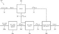
오디오 신호(55)를 처리하기 위한 오디오 프로세서가 도시된다. 오디오 프로세서는 시간 프레임(75a)을 위하여 오디오 신호의 위상 측정(80)을 계산하도록 구성되는 오디오 신호 위상 측정 계산기(60), 시간 프레임(75a)을 위한 표적 위상 측정을 결정하기 위한 표적 위상 측정 결정기(65) 및 처리된 오디오 신호(90)를 획득하도록 시간 프레임(75a)을 위한 계산된 위상 측정(80) 및 상기 표적 위상 측정(85)을 사용하여 상기 오디오 신호(55)의 위상들(45)을 보정하도록 구성되는 위상 보정기(70);를 포함한다.An audio processor for processing the audio signal 55 is shown. The audio processor includes an audio signal phase measurement calculator 60 configured to calculate a phase measurement 80 of the audio signal for a time frame 75a, a target phase measurement determiner 70 for determining a target phase measurement for the time frame 75a, (45) of the audio signal (55) using the calculated phase measurement (80) for the time frame (75a) and the target phase measurement (85) to obtain the processed audio signal (65) And a phase corrector 70 configured to correct the phase difference.
Description
본 발령은 오디오 신호의 처리를 위한 오디오 프로세서와 방법, 그리고 오디오 신호의 디코딩을 위한 디코더와 방법, 및 오디오 신호의 인코딩을 위한 인코더와 방법에 관한 것이다. 게다가, 위상 보정 데이터를 결정하기 위한 계산기와 방법, 및 이전에 언급된 방법들 중 하나를 실행하기 위한 컴퓨터 프로그램과 방법이 설명된다. 바꾸어 말하면, 본 발명은 지각적 오디오 코덱들을 위한 위상파생적 보정과 대역폭 확장(BWE) 또는 지각적 중요성을 기초로 하여 QMF 도메인 내의 대역폭 확장된 신호들의 위상 스펙트럼의 보정을 나타낸다.The present invention relates to an audio processor and method for processing an audio signal, a decoder and method for decoding an audio signal, and an encoder and method for encoding an audio signal. In addition, a computer and a method for determining phase correction data, and a computer program and method for performing one of the previously mentioned methods are described. In other words, the present invention represents a correction of the phase spectrum of the bandwidth extended signals in the QMF domain based on phase-dependent correction and bandwidth extension (BWE) or perceptual importance for perceptual audio codecs.
지각적 오디오 코딩Perceptual audio coding
지금까지 지각적 오디오 코딩은 시간/주파수-도메인 처리의 사용, 중복 감소(redundancy reduction, 엔트로피 코딩), 및 지각적 효과들의 단호한 설명을 통한 무관성(irrelevancy) 제거를 포함하는, 몇몇 통상적인 주제들을 따른다.[1]. 일반적으로, 입력 신호는 시간 도메인 신호를 스펙트럼(시간/주파수 표현으로 전환하는 분석 필터 뱅크에 의해 분석된다. 스펙트럼 계수들로의 전환은 그것들의 주파수 콘텐츠(예를 들면, 그것들의 개별 배음 구조를 갖는 상이한 악기들)를 기초로 하여 신호 성분들의 선택적 처리를 허용한다.Perceptual audio coding has hitherto been used for some common topics, including the use of time / frequency-domain processing, redundancy reduction (entropy coding), and irrelevancy removal through a decisive description of perceptual effects [1]. In general, the input signal is analyzed by an analysis filter bank that converts the time domain signal into a spectrum (time / frequency representation.) The conversion to spectral coefficients is done by converting their frequency content (e.g., Lt; / RTI > different instruments).
일반적으로, 입력 신호는 지각적 특성들과 관련하여 분석되는데, 즉 특히 시간- 및 주파수-의존적 마스킹 임계Imasking threshold)가 계산된다. 시간/주파수 의존적 마스킹 임계는 각각의 주파수 대역 및 코딩 시간 프레임을 위한 절대 에너지 값 또는 마스크-대-신호-비율(MSR)의 형태의 표적 코딩 임계를 통하여 양자화 유닛에 전달된다.In general, the input signal is analyzed in relation to perceptual characteristics, in particular a time-and frequency-dependent masking threshold, is calculated. The time / frequency dependent masking threshold is communicated to the quantization unit through a target coding threshold in the form of an absolute energy value or mask-to-signal-ratio (MSR) for each frequency band and coding time frame.
분석 필터 뱅크에 의해 전달되는 스펙트럼 계수들은 신호의 표현을 위하여 필요한 데이터 비율을 감소시키도록 양자화된다. 이러한 단계는 정보의 손실을 나타내고 신호 내로 코딩 왜곡(오류, 잡음)을 도입한다. 이러한 코딩 잡음의 청각 영향을 최소화하기 위하여, 양자화 단계 크기들은 각각의 주파수 대역 및 프레임을 위한 표적 코딩 임계들에 따라 제어된다. 이상적으로, 각각의 주파수 대역 내로 주입된 코딩 잡음은 코딩(마스킹) 임계보다 낮고 따라서 대상 오디오의 저하는 지각할 수 있다(무관성의 제거) 음향심리학적 요구조건들에 따른 주파수 및 시간에 대한 양자화 잡음의 이러한 제어는 복접한 잡음 형상 효과에 이르게 하고 코더를 지각적 오디오 코더로 만드는 것이다.The spectral coefficients conveyed by the analysis filter bank are quantized to reduce the data rate needed for representation of the signal. This step represents the loss of information and introduces coding distortion (error, noise) into the signal. In order to minimize the auditory influence of this coding noise, the quantization step sizes are controlled according to the target coding thresholds for each frequency band and frame. Ideally, the coding noise injected into each frequency band is lower than the coding (masking) threshold and therefore the degradation of the target audio may be perceptible (elimination of the non-affinities). Quantization noise for frequency and time according to acoustic psychological requirements This control leads to a recurrent noise shape effect and makes the coder a perceptual audio coder.
그 뒤애, 현대 오디오 코더들은 양자화된 스펙트럼 데이터 상에 엔트로피 코딩(예를 들면, 호프만 코딩, 산술 코딩)을 실행한다. 엔트로피 코딩은 비트 레이트를 더 절약하는, 무손실 코딩 단계이다.Subsequently, modern audio coders perform entropy coding (e.g., Hoffman coding, arithmetic coding) on the quantized spectral data. Entropy coding is a lossless coding step that further saves the bit rate.
마지막으로, 모든 코딩된 스펙트럼 데이터 및 관련 부가적인 파라미터들(예를 들면, 각각의 주파수 대역을 위한 양자화기 설정들 같은, 부가 정보)은 비트스트림 내로 함께 패킹되고, 이는 파일 저장 또는 전송을 위하여 의도되는 최종 코딩된 표현이다.Finally, all the coded spectral data and the associated additional parameters (e.g., additional information, such as quantizer settings for each frequency band) are packed together into a bitstream, which is intended for file storage or transmission Lt; / RTI >
대역폭 확장Bandwidth expansion
필터뱅크들을 기초로 하는 지각적 오디오 코딩에서, 소비된 비트 레이트의 주요 부분은 일반적으로 양자화된 스펙트럼 계수들 상에서 소비된다. 따라서, 매우 낮은 비트 레이트들에서, 충분하지 않은 비트들은 지각적으로, 손상되지 않은 재생을 달성하는데 필요한 정밀도로 모든 계수를 표현하도록 이용 가능할 수 있다. 이에 의해, 낮은 비트 레이트 요구조건들은 지각적 오디오 코딩에 의해 획득될 수 있는 오디오 대역폭에 대한 한계를 효율적으로 설정한다. 대역폭 확장[2]은 이러한 오랫동안의 기본 한계를 제거한다. 대역폭 확장의 중심 개념은 간결한 파라미터 형태로 송실 고주파수 콘텐츠를 전송하고 저장하는 부가적인 고주파수 프로세서에 의해 대역 제한된 지각적 코딩을 완성하는 것이다. 고주파수 콘텐츠는 스펙트럼 대역 복제(SBR)[3]에서 사용되는 것 같은 카피-업(copy-up) 기술들 상의 또는 예를 들면 보코더[4] 같은 피치 시프팅(pitch dhifting) 기술들의 적용 상의, 기저대역 신호의 부대역 변조를 기초로 하여 발생될 수 있다. In perceptual audio coding based on filter banks, the major part of the bit rate consumed is generally consumed on the quantized spectral coefficients. Thus, at very low bit rates, insufficient bits may be available perceptually to represent all the coefficients with the precision needed to achieve undamaged reproduction. Thereby, the low bit rate requirements effectively set limits on the audio bandwidth that can be obtained by perceptual audio coding. Bandwidth extension [2] eliminates this long-standing baseline. The central idea of bandwidth extension is to complete perceptually coded band-limited by an additional high-frequency processor that transmits and stores the transmitted high-frequency content in the form of concise parameters. The high frequency content can be used for a variety of purposes, such as on the copy-up techniques as used in spectral band replication (SBR) [3] or on the application of pitch dhifting techniques such as for example vocoder [4] Lt; / RTI > can be generated based on subband modulation of the band signal.
디지털 오디오 효과들Digital audio effects
시간-스트레칭(stretching) 또는 피치 시프팅 효과들은 일반적으로 동기화된 오버랩-가산(synchronized overlap-add, SOLA) 같은 시간 도메인 기술들 또는 주파수 도메인 기술들(보코더)의 적용에 의해 획득된다. 또한, 부대역들 내에 SOLA 처리를 적용하는 하이브리드 시스템들이 제안되어왔다. 보코더들 및 하이브리드 시스템들은 일반적으로 페이스니스(phasiness)로 불리는 아티팩트로부터 곤란을 겪는다. 일부 공보들은 중요한 수직 위상 간섭의 보존에 의해 향상을 시간 스트레칭 알고리즘들의 음향 음질과 괸련시킨다[6][7].Time-stretching or pitch shifting effects are generally obtained by application of time domain techniques such as synchronized overlap-add (SOLA) or frequency domain techniques (vocoder). Hybrid systems have also been proposed that apply SOLA processing within subbands. Vocoders and hybrid systems suffer from artifacts commonly referred to as phasiness. Some bulletins enhance the sound quality of time stretching algorithms by preserving important vertical phase interference [6] [7].
최신 오디오 코더들[1]은 일반적으로 코딩되려는 신호의 중요한 위상 특성들을 무시함으로써 오디오 신호들의 지각적 품질을 절충한다. 지각적 오디오 코더들 aso의 위상 간섭의 보정의 제안이 다뤄진다[9].Modern audio coders [1] typically compromise the perceptual quality of audio signals by ignoring important phase characteristics of the signal to be coded. A proposal for correction of the phase interference of the perceptual audio coders aso is dealt with [9].
그러나, 모든 종류의 위상 간섭 오류는 동시에 보정될 수 있고 모든 위상 간섭 오류가 지각적으로 중요하지는 않다. 예를 들면, 오디오 대역폭 확장에서, 최신 기술로부터, 어떠한 위상 간섭 관련 오류들이 높은 최우선으로 보정되어야만 하고 어떠한 오류들이 그것들의 상당한 지각적 영향과 관련하여 단지 부분적으로 보정될 수 있는지, 도는 전체가 무시되는지는 분명하지 않다.However, all kinds of phase interference errors can be corrected at the same time, and not all phase interference errors are perceptually significant. For example, in an audio bandwidth extension, from the state of the art, it can be determined that any phase interference related errors must be corrected to high priority and that any errors can only be partially corrected with respect to their significant perceptual effect, Is not clear.
특히, 오디오 대역폭 확장[2][3][4]의 적용에 기인하여, 주파수 및 시간에 대한 위상 간섭은 흔히 손상된다. 결과는 청각 거칠기를 나타내고 원래 신호 내의 창각 오브젝트들로부터 분해되고 따라서 원래 신호에 부가적으로 스스로 청각 오브젝트로서 지각되는 부가적으로 지각된 톤(tone)들을 포함할 수 있는 탁한(dull) 음성이다. 게다가, 음성은 또한 멀리서부터 오는 것으로 나타나고, 덜 "신나며*buzzy), 따라서 적은 청취 참여를 자아낸다.In particular, due to the application of audio bandwidth extensions [2] [3] [4], phase interference with frequency and time is often impaired. The result is a dull voice that represents the auditory roughness and may include additional perceived tones that are decomposed from the window objects in the original signal and thus are perceived as an auditory object in addition to the original signal. In addition, the voice also appears to come from a distance, less "buzzy" and thus less auditory participation.
따라서, 향상된 접근법을 위한 필요성이 존재한다.Thus, there is a need for an improved approach.
오디오 신호를 처리하기 위한 향상된 개념을 제공하는 것이 본 발명의 목적이다. 이러한 목적은 독립 청구항들의 주제에 의해 해결된다It is an object of the present invention to provide an improved concept for processing audio signals. This objective is solved by the subject matter of the independent claims
본 발명은 오디오 신호의 위상이 오디오 프로세서 또는 디코더에 의해 계산되는 표적 위상에 따라 보정될 수 있다는 발견을 기초로 한다. 표적 위상은 처리되지 않은 오디오 신호의 위상의 표현으로서 보일 수 있다. 따라서, 처리된 오디오 신호의 위상은 처리되지 않은 오디오 신호의 위상과 잘 들어맞도록 보정된다. 예를 들면 오디오 신호의 시간 주파수 표현을 가질 때, 오디오 신호의 위상은 뒤따르는 주파수 부대역들을 위하여 시간 프레임 내에 보정될 수 있다. 설명된 발견들은 다른 실시 예들에서 구현될 수 있거나 또는 디코더 및/또는 인코더에서 공동으로 구현될 수 있다.The present invention is based on the discovery that the phase of an audio signal can be corrected according to the target phase calculated by the audio processor or decoder. The target phase may be viewed as a representation of the phase of the unprocessed audio signal. Thus, the phase of the processed audio signal is corrected to fit well with the phase of the unprocessed audio signal. For example, when having a time-frequency representation of an audio signal, the phase of the audio signal may be corrected within a time frame for subsequent frequency subbands. The described discoveries may be implemented in other embodiments or may be implemented jointly in a decoder and / or encoder.
실시 예들은 시간 프레임을 위한 오디오 신호의 위상 측정을 계산하도록 구성되는 오디오 신호 위상 측정 계산기를 포함하는 오디오 신호의 처리를 위한 오디오 프로세서를 도시한다. 게다가, 오디오 신호는 상기 시간 프레임을 위한 표적 위상 측정을 결정하기 위한 표적 위상 측정 결정기(target phase measurement determiner) 및 처리된 오디오 신호를 획득하기 위하여 계산된 위상 측정 및 표적 위상 측정을ㅇ 사용하여 오디오 프레임을 위한 오디오 신호들의 위상을 보정하도록 구성되는 위상 보정기(phase correctore)를 포함한다.Embodiments illustrate an audio processor for processing an audio signal comprising an audio signal phase measurement calculator configured to calculate a phase measurement of an audio signal for a time frame. In addition, the audio signal may include a target phase measurement determiner to determine a target phase measurement for the time frame, and a phase measurement and target phase measurement computed to obtain the processed audio signal, And a phase corrector configured to correct the phase of the audio signals for the audio signal.
또 다른 실시 예들에 따르면, 오디오 신호는 시간 프레임을 위한 복수의 부대역 신호를 포함할 수 있다. 표적 위상 측정 결정기는 제 1 부대역 신호를 위한 제 1 표적 위상 측정 및 제 2 부대역 신호를 위한 제 2 표적 위상 측정을 결정하도록 구성된다. 게다가, 오디오 신호 위상 측정 계산기는 제 1 부대역 신호를 위한 제 1 표적 위상 측정 및 제 2 부대역 신호를 위한 제 2 표적 위상 측정을 결정한다. 위상 보정기는 오디오 신호의 위상 측정을 사용하여 제 1 부대역 신호를 위한 제 1 위상을 보정하고 오디오 신호의 제 2 위상 측정 및 제 2 표적 위상 측정을 사용하여 제 2 부대역의 제 2 위상을 보정하도록 구성된다. 따라서 오디오 프로세서는 보정된 제 1 부대역 신호 및 보정된 제 2 부대역 신홀을 사용하여 보정된 오디오 신호를 합성하기 위한 오디오 신호 합성기(audio signal synthesizer)를 포함할 수 있다.According to yet other embodiments, the audio signal may comprise a plurality of sub-band signals for a time frame. The target phase measurement determiner is configured to determine a first target phase measurement for the first sub-band signal and a second target phase measurement for the second sub-band signal. In addition, the audio signal phase measurement calculator determines a first target phase measurement for the first sub-band signal and a second target phase measurement for the second sub-band signal. The phase compensator uses the phase measurement of the audio signal to correct the first phase for the first subband signal and the second phase measurement of the audio signal and the second target phase measurement to correct the second phase of the second subband . Thus, the audio processor may include an audio signal synthesizer for synthesizing the corrected audio signal using the corrected first sub-band signal and the corrected second sub-band enhancement.
본 발명에 따르면, 오디오 프로세서는 수평 방향으로, 즉 시간에 대한 보정으로 오디오 신호의 위상을 보정하도록 구성된다. 따라서, 오디오 신호는 시간 프레임들의 세트로 세분될 수 있으며, 각각의 시간 프레임의 위상은 표적 위상에 따라 보정될 수 있다. 표적 위상은 원래 오디오 신호의 표현일 수 있으며, 오디오 프로세서는 원래 오디오 신호의 인코딩된 표현인 오디오 신호의 디코딩을 위한 디코더의 일부분일 수 있다. 선택적으로, 수평 위상 보정은 만일 오디오 신호가 시간-주파수 표현 내에서 이용 가능하면, 오디오 신호의 부대역들의 수를 위하여 개별적으로 적용될 수 있다. 오디오 신호의 위상의 보정은 표적 위상의 시간에 대한 위상 유도 및 오디오 신호의 위상으로부터 오디오 신호의 위상의 변이를 뺌으로써 실행될 수 있다.According to the invention, the audio processor is configured to correct the phase of the audio signal in a horizontal direction, i.e. with a correction to the time. Thus, the audio signal can be subdivided into a set of time frames, and the phase of each time frame can be corrected according to the target phase. The target phase may be a representation of the original audio signal and the audio processor may be part of a decoder for decoding an audio signal that is an encoded representation of the original audio signal. Alternatively, the horizontal phase correction may be applied separately for the number of subbands of the audio signal, if the audio signal is available in the time-frequency representation. Correction of the phase of the audio signal can be performed by subtracting the phase shift of the audio signal from the phase of the audio signal and the phase of the target phase with respect to time.
따라서, 시간에 대한 위상 유도가 주파수(3-1, 4-2는 위상)이기 때문에, 설명된 위상 보정은 오디오 신호의 각각의 부대역을 위한 주파수 보정을 실행한다. 바꾸어 말하면, 표적 주파수에 대한 오디오 신호의 각각의 부대역의 차이는 오디오 신호를 위한 더 나은 품질을 획득하도록 감소될 수 있다.Thus, since the phase induction with respect to time is frequency (3-1, 4-2 is phase), the described phase correction performs frequency correction for each subband of the audio signal. In other words, the difference of each subband of the audio signal relative to the target frequency can be reduced to obtain a better quality for the audio signal.
표적 위상을 결정하기 위하여, 표적 위상 결정기는 현재 시간 프레임을 위한 기본 주파수 추정을 획득하고 시간 프레임을 위한 기본 주파수 추정을 사용하여 시간 프레임을 위한 복수의 부대역의 각각의 부대역을 위한 주파수 추정을 계산하도록 구성된다. 주파수 추정은 부대역들의 총 수 및 오디오 신호의 샘플링 주파수를 사용하여 시간에 대한 위상 유도로 전환될 수 있다. 또 다른 실시 예에서, 오디오 프로세서는 시간 프레임 내의 오디오 신호를 위한 표적 위상 측정을 결정하기 위한 표적 위상 측정 결정기, 오디오 신호의 위상을 사용하여 위상 오류(phase error)를 계산하기 위한 위상 오류 계산기, 및 위상 오류를 사용하여 오디오 신호 및 시간 프레임의 위상을 보정하도록 구성되는 위상 보정기를 포함한다.To determine the target phase, the target phase determiner obtains a base frequency estimate for the current time frame and uses the base frequency estimate for the time frame to estimate the frequency for each subband of the plurality of subbands for the time frame . The frequency estimate can be converted to phase induction over time using the total number of subbands and the sampling frequency of the audio signal. In another embodiment, the audio processor comprises a target phase measurement determiner for determining a target phase measurement for an audio signal in a time frame, a phase error calculator for calculating a phase error using the phase of the audio signal, And a phase corrector configured to correct the phase of the audio signal and the time frame using the phase error.
또 다른 실시 예들에 따르면, 오디오 신호는 시간 주파수 표현 내에서 이용 가능하며, 오디오 신호는 시간 프레임을 위한 복수의 부대역을 포함한다. 표적 위상 측정 결정기는 제 1 부대역 신호를 위한 제 1 표적 위상 측정 및 제 2 부대역 신호를 위한 제 2 표적 위상 측정을 결정한다. 게다가, 위상 오류 계산기는 위상 오류들의 벡터를 형성하며, 벡터의 제 1 요소는 제 1 부대역 신호 및 제 1 표적 위상 측정의 위상의 제 1 유도를 언급하고 벡터의 제 2 요소는 제 2 부대역 신호 및 제 2 표적 위상 측정의 위상의 제 2 유도를 언급한다. 부가적으로, 이러한 실시 예에서의 오디오 프로세서는 보정된 제 1 부대역 신호 및 보정된 제 2 부대역 신호를 사용하여 보정된 오디오 신호를 합성하기 위한 오디오 신호 합성기를 포함한다. 이러한 위상 보정은 평균적으로 보정된 위상 값들을 생산한다.According to yet other embodiments, the audio signal is available in a time frequency representation, and the audio signal includes a plurality of subbands for a time frame. The target phase measurement determiner determines a first target phase measurement for the first sub-band signal and a second target phase measurement for the second sub-band signal. In addition, the phase error calculator forms a vector of phase errors, where the first element of the vector refers to the first derivation of the first sub-band signal and the phase of the first target phase measurement, and the second element of the vector refers to the second sub- Signal and a second derivation of the phase of the second target phase measurement. Additionally, the audio processor in this embodiment includes an audio signal synthesizer for synthesizing the corrected audio signal using the corrected first sub-band signal and the corrected second sub-band signal. This phase correction produces average corrected phase values.
부가적으로 또는 대안으로서, 복수의 부대역은 기저대역 및 주파수 패치들의 세트로 그룹화되며, 기저대역은 오디오 신호의 하나의 부대역을 포함하고 주파수 패치들의 세트는 기저대역 내의 적어도하나의 부대역의 주파수보다 높은 주파수에서 기저대역의 적어도 하나의 부대역을 포함한다. 또 다른 실시 예들은 평균 위상 오류를 획득하기 위하여 주파수 패치들의 제 2 수의 제 1 패치를 언급하는 위상 로류들의 벡터의 요소들의 평균을 계산하도록 구성되는 위상 오류 계산기를 도시한다. 위상 보정기는 가중된 평균 위상 오류를 사용하여 패치 신호의 주파수 패치들의 세트의 제 1 및 뒤따르는 주파수 패치들 내의 부대역 신호의 위상을 보정하도록 구성되며, 평균 위상 오류는 변형된 패치 신호를 획득하도록 주파수 패치의 지수에 따라 세분된다. 위상 보정은 교차 주파수들에서 뛰어난 품질을 제공하며, 이는 뒤따르는 주파수 패치들 사이의 경계 주파수들이다.Additionally or alternatively, the plurality of subbands may be grouped into a set of baseband and frequency patches, wherein the baseband comprises one subband of the audio signal and the set of frequency patches comprises at least one subband within the baseband At least one subband of the baseband at a frequency higher than the frequency. Still other embodiments illustrate a phase error calculator configured to calculate an average of the elements of a vector of phase rheods referring to a first number of patches of a second number of frequency patches to obtain an average phase error. The phase corrector is configured to use the weighted average phase error to correct the phase of the subband signal in the first and subsequent frequency patches of the set of frequency patches of the patch signal, It is subdivided according to the exponent of the frequency patch. Phase correction provides excellent quality at crossover frequencies, which are boundary frequencies between subsequent frequency patches.
또 다른 실시 예에 따르면, 두 가지 이전에 설명된 실시 예는 평균적으로 그리고 크로스오버 주파수들에서 뛰어난 위상 보정된 값들을 포함하는 보정된 오디오 신호를 획득하도록 결합될 수 있다. 따라서, 오디오 신호 위상 유도 계산기는 기저대역을 위한 주파수에 대힌 위상 유도들의 평균을 계산하도록 구성된다. 위상 보정기는 오디오 신호의 기저대역 내의 가장 높은 부대역 지수를 갖는 부대역 신호의 위상에 대하여 현재 부대역 지수에 의해 가중된 주파수에 대한 위상 유도들의 평균을 더함으로써 최적화된 제 1 주파수 패치로 또 다른 변형된 패치 신호를 계산한다. 게다가, 위상 보정기는 결합되고 변형된 패치 신호를 획득하도록 변형된 패치 신호 및 또 다른 변형된 패치 신호의 가중 평균을 계산하고 주파수 패치들을 기초로 하여, 결합되고 변형된 패치 신호의 이전 주파수 패치 내의 가장 높은 부대역 지수를 갖는 부대역 신호의 위상에 대하여 현재 부대역의 부대역 지수에 의해 가중된, 주파수에 대한 위상 유도들의 평균을 더함으로써 결합되고 변형된 패시 신호를 반복적으로 업데이트하도록 구성될 수 있다.According to yet another embodiment, two previously described embodiments can be combined to obtain a corrected audio signal that includes excellent phase corrected values on average and at crossover frequencies. Thus, the audio signal phase derivation calculator is configured to calculate an average of the phase inductions with respect to the frequency for the baseband. The phase corrector is further adapted to add a second frequency to the optimized first frequency patch by adding an average of the phase inductions for the frequency weighted by the current subband magnitude index to the phase of the subband signal with the highest subband index in the baseband of the audio signal. The modified patch signal is calculated. In addition, the phase compensator calculates a weighted average of the modified patch signal and another modified patch signal to obtain a combined and modified patch signal, and calculates a weighted average of the modified patch signal based on the frequency patches, And may be configured to iteratively update the combined and modified pass signal by adding an average of the phase inductions for the frequency, weighted by the subband magnitude of the current subband with respect to the phase of the subband signal with the high subband exponent .
표적 위상을 결정하기 위하여, 표적 위상 측정 결정기는 데이터 스트림으로부터 오디오 신호의 현재 시간 프레임 내의 피크 위치 및 피크 위치들의 기본 주파수를 추출하도록 구성되는 데이터 스트림 추출기(data stream extractor)를 포함할 수 있다. 대안으로서, 표적 위상 측정 결정기는 현재 시간 프레임을 분석하도록 구성되는 오디오 신호 뷴석기*audio signal analyzer)를 포함할 수 있다. 게다가. 표적 위상 측정 결정기는 피크 위치 및 피크 위치들의 기본 주파수를 사용하여 현재 시간 프레임 내의 또 다른 피크 위치들을 추정하기 위한 표적 스펙트럼 발생기를 포함한다. 상세히 설명하면, 표적 스펙트럼 발생기는 시간의 펄스 트레인(pulse train)을 발생시키기 위한 피크 검출기, 피크 위치들의 기본 주파수에 따른 펄스 트레인의 주파수를 보정하기 위한 신호 형성기(signal former), 및 보정된 펄스 트레인의 위상 스펙트럼을 발생시키기 위한 스펙트럼 분석기를 포함하며, 시간 도메인 신호의 펄스 스펙트럼은 표적 위상 측정이다. 표적 위상 측정 결정기의 설명된 실시 예는 피크들을 갖는 파형을 갖는 오디오 신호를 위한 표적 스펙트럼의 발생을 위하여 바람직하다,To determine the target phase, the target phase measurement determiner may include a data stream extractor configured to extract a fundamental frequency of peak positions and peak positions within the current time frame of the audio signal from the data stream. Alternatively, the target phase measurement determiner may comprise an audio signal analyzer configured to analyze the current time frame. Besides. The target phase measurement determiner includes a target spectral generator for estimating other peak positions within the current time frame using the peak frequency and the fundamental frequency of the peak positions. In detail, the target spectrum generator includes a peak detector for generating a pulse train of time, a signal former for correcting the frequency of the pulse train according to the fundamental frequency of the peak positions, And a pulse spectrum of the time domain signal is a target phase measurement. The described embodiment of the target phase measurement determiner is preferred for the generation of a target spectrum for an audio signal having a waveform with peaks,
제 2 오디오 프로세서의 실시 예들은 수직 위상 상관을 설명한다. 수직 위상 상관은 모든 기저대역에 대하여 하나의 시간 프레임 내의 오디오 신호의 위상을 보정한다. 각각의 부대역을 위하여 독립적으로 적용되는, 오디오 신호의 위상의 보정은 오디오 신호의 부대역의 합성 후에, 보정되지 않은 오디오 신호와 다른 오디오 신호의 파형을 야기한다. 따라서, 예를 들면, 스미어링된(smeared) 피크 또는 트랜지언트를 재형상화하는 것이 가능하다.Embodiments of the second audio processor describe vertical phase correlation. Vertical phase correlation corrects the phase of the audio signal in one time frame for all baseband. Correction of the phase of the audio signal, which is applied independently for each subband, causes the waveform of the audio signal to differ from the uncorrected audio signal after synthesis of the subband of the audio signal. Thus, for example, it is possible to reshape the smeared peak or transient.
또 다른 실시 예에 따르면, 제 1 및 제 2 변이 모드 내의 오디오 신호의 위상의 변이를 결정하기 위한 변이 결정기, 위상 변이 모드를 사용하여 결정되는 제 1 변이 및 제 2 변이 모드를 사용하여 결정되는 제 2 변이를 비교하기 위한 변이 비교기(variation comparator), 및 비교의 결과를 기초로 하여 제 1 변이 모드 또는 제 2 변이 노드에 따라 위상 보정을 계산하기 위한 보정 데이터 계산기를 갖는 오디오 신호를 위한 위상 보정 데이터를 결정하기 위한 계산기가 도시된다.According to yet another embodiment, there is provided an apparatus comprising: a variator for determining a variation in phase of an audio signal in first and second variation modes; a first variation determined using a phase variation mode; and a second variation determined using a second variation mode And a correction data calculator for calculating a phase correction according to the first variation mode or the second variation node based on the result of the comparison, the phase correction data for the audio signal having the correction data calculator for calculating the phase correction according to the first variation mode or the second variation node, Lt; / RTI > is shown.
또 다른 실시 예는 제 1 변이 노드 내의 위상의 변이로서 오디오 신호의 복수의 시간 프레임을 위한 시간에 대한 위상 유도(PDT)의 표준 편차 측정 또는 제 2 변이 모드 내의 위상의 변이로서 복수의 부대역을 위한 시간에 대한 위상 유도(PDF)의 표준 편차 측정을 결정하기 위한 변이 결정기를 도시한다. 변이 비교기는 제 1 변이 모드로서 시간에 대한 위상 유도의 측정 및 오디오 신호의 시간 프레임들을 위한 제 2 변이 모드로서 주파수에 대한 위상 유도의 측정을 비교한다. 또 다른 실시 예에 따르면, 변이 결정기는 제 3 변이 모드 내의 오디오 신호의 위상의 변이를 결정하도록 구성되며, 제 3 변이 모드는 트랜지언트 검출 모드이다. 따라서, 변이 비교기는 3가지 변이 모드를 비교를 비교하고 보정 데이터 계산기는 비교의 결과를 기초로 하여 제 1 변이 모드, 제 2 변이 모드, 또는 제 3 변이 모드에 따라 위상 보정을 계산한다.Another embodiment is a method of measuring a standard deviation of a phase lead (PDT) for a time for a plurality of time frames of an audio signal as a variation of a phase within a first variation node or a variation of a phase within a second variation mode, Lt; RTI ID = 0.0 > (PDF). ≪ / RTI > The transient comparator compares the measurement of phase induction with respect to time as a first variation mode and the measurement of phase induction with respect to frequency as a second variation mode for time frames of the audio signal. According to yet another embodiment, the variation determiner is configured to determine the phase shift of the audio signal in the third variation mode, and the third variation mode is the transient detection mode. Thus, the variation comparator compares the three variation modes for comparison, and the correction data calculator calculates the phase correction according to the first variation mode, the second variation mode, or the third variation mode based on the result of the comparison.
보정 데이터 계산기의 결정 규칙들은 다음과 같이 설명될 수 있다. 만일 트랜지언트가 검출되면, 위상은 트랜지언트의 형상을 회복하도록 트랜지언트들을 위한 위상 보정에 따라 보정된다. 그렇지 않으면, 만일 제 1 변이가 제 2 변이보다 작거나 동일하면, 제 1 변이 모드의 위상 보정이 적용되거나 또는, 만일 제 2 변이가 제 1 변이보다 크면, 제 2 변이 모드에 따라 위상 보정이 적용된다.만일 트랜지언트의 부재가 검출되고 만일 제 1 변이 모드 및 제 2 변이 모드 모두가 임계 값을 초과하면, 어떠한 위상 보정 모드도 적용되지 않는다.The decision rules of the correction data calculator can be described as follows. If a transient is detected, the phase is corrected according to the phase correction for the transients to recover the shape of the transient. Otherwise, if the first variation is less than or equal to the second variation, then phase correction of the first variation mode is applied, or if the second variation is greater than the first variation, phase correction is applied according to the second variation mode If no transient is detected and if both the first transition mode and the second transition mode exceed the threshold, no phase correction mode is applied.
계산기는 최상의 위상 보정 모드를 결정하고 결정된 위상 보정 모드를 위한 관련 파라미터들을 계산하도록, 예를 들면 오디오 보정 스테이지 내의 오디오 신호를 분석하도록 구성될 수 있다. 디코딩 스테이지에서, 파라미터들은 최신 코덱들을 사용하여 디코딩된 신호들과 비교하여 더 ask은 품질을 갖는 디코딩된 오디오 신호를 획득하도록 사용될 수 있다. 계산기는 오디오 신호의 각각의 시간 프레임을 위하여 올바른 보정 모드를 자동으로 검출한다는 것을 이해하여야만 한다.The calculator may be configured to determine the best phase correction mode and to calculate the relevant parameters for the determined phase correction mode, e.g., to analyze the audio signal in the audio correction stage. In the decoding stage, the parameters may be used to obtain a decoded audio signal with more asking quality compared to the decoded signals using the latest codecs. It should be understood that the calculator automatically detects the correct calibration mode for each time frame of the audio signal.
실시 예들은 제 1 보정 데이터를 사용하여 오디오 신호의 제 2 신호의 제 1 시간 BMFP임을 위한 표적 스펙트럼을 발생시키기 위한 제 1 표적 스펙트럼 발생기 및 위상 보정 알고리즘으로 결정된 오디오 신호의 제 1 시간 프레임 내의 부대역 신호의 위상을 보정하기 위한 제 1 위상 보정기를 갖는 오디오 신호를 디코딩하기 위한 디코더를 도시하며, 보정은 오디오 신호 및 표적 스펙트럼의 제 1 시간 프레임 내의 부대역 신호의 측정 사이의 차이의 감소에 의해 실행된다. 부가적으로, 디코더는 시간 프레임을 위한 보정된 위상을 사용하여 제 1 시간 프레임을 위한 오디오 부대역 신호를 계산하고 제 2 시간 프레임 내의 부대역 신호의 측정을 사용하거나 또는 위상 보정 알고리즘과 다른 또 다른 위상 보정 알고리즘에 따라 보정된 위상 계산을 사용하여 제 1 시간 프레임과 다른 제 2 시간 프레임을 위한 오디오 부대역 신호를 계산하기 위한 오디오 부대역 신호 계산기를 포함한다. Embodiments include a first target spectrum generator for generating a target spectrum for a first time BMFP of a second signal of an audio signal using first correction data and a second target spectral generator for generating a subband A decoder for decoding an audio signal having a first phase corrector for correcting the phase of the signal, the correction being performed by a reduction in the difference between the measurement of the audio signal and the subband signal in the first time frame of the target spectrum do. Additionally, the decoder may use the corrected phase for the time frame to calculate the audio sub-band signal for the first time frame and use the measurement of the sub-band signal in the second time frame, And an audio sub-band signal calculator for calculating an audio sub-band signal for a second time frame different from the first time frame using the corrected phase calculation according to a phase correction algorithm.
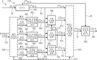
또 다른 실시 예들에 따르면, 디코더는 제 1 표적 스펙트럼 발생에 등가물이고 제 1 위상 보정기에 등가물인 제 2 및 제 3 위상 보정기에 등가물인 제 2 및 제 3 표적 스펙트럼 발생기를 포함한다. 또 다른 실시 예에 따르면 디코더는 오디오 신호와 관련하여 감소된 수의 부대역을 갖는 시간 프레임 내의 오디오 신호를 디코딩하도록 구성되는 코어 디코더를 포함한다. 게다가, 디코더는 감소된 수의 부대역들을 갖는 코어 디코딩된 오디오 신호의 세트를 패칭하기 위한 패처(patcher)를 포함할 수 있으며, 부대역들의 세트는 규칙적인 부대역들의 수를 갖는 오디오 신호를 획득하도록, 감소된 수의 부대역들과 근접한, 시간 프레임 내의 또 다른 부대역들에 제 1 패치를 형성한다. 게다가, 디코더는 시간 프레임 내의 오디오 서브 대역 신호 내의 크기 값들을 처리하기 위한 크기 프로세서(magnitude processor) 및 합성되고 디코딩된 오디오 신호를 획득하도록 오디오 부대역 신호들 또는 처리된 오디오 부대역 신호들의 크기를 합성하기 위한 신호 합성기를 포함할 수 있다. 이러한 실시 예는 디코딩된 오디오 신호의 위상 보정을 포함하는 대역폭 확장을 위한 디코더를 달성할 수 있다.According to yet other embodiments, the decoder includes second and third target spectral generators, which are equivalents to the first target spectral generation and equivalents to the second and third phase correlators, which are equivalent to the first phase corrector. According to yet another embodiment, a decoder includes a core decoder configured to decode an audio signal in a time frame having a reduced number of subbands with respect to the audio signal. In addition, the decoder may include a patcher for fetching a set of core decoded audio signals with a reduced number of subbands, and the set of subbands may be obtained by acquiring an audio signal having a number of regular subbands To form a first patch in another subband in the time frame, which is close to the reduced number of subbands. In addition, the decoder may comprise a magnitude processor for processing magnitude values in the audio subband signal in a time frame and a magnitude processor for synthesizing the magnitudes of the audio sub-signals or processed audio sub-signals to obtain a synthesized and decoded audio signal And a signal synthesizer for performing the operation. This embodiment can achieve a decoder for bandwidth extension that includes phase correction of the decoded audio signal.
따라서, 오디오 신호의 위상을 결정하기 위한 위상 결정기, 결정된 오디오 신호의 위상을 기초로 하여 오디오 신호를 위한 위상 보정 데이터를 결정하기 위한 계산기, 오디오 신호와 관련하여 감소된 수의 부대역을 갖는 코어 인코딩된 오디오 신호를 획득하도록 오디오 신호를 코어 인코딩하도록 구성되는 코어 인코더, 및 코어 인코딩된 오디오 신호 내에 포함되지 않는 부대역들의 제 2 세트를 위한 저해상도 파라미터 표현을 획득하도록 오디오 신호의 파라미터들을 추출하도록 구성되는 파라미터 추출기, 그리고 파라미터들, 코어 인코딩된 오디오 신호, 및 위상 보정 데이터을 포함하는 출력 신호를 형성하기 위한 오디오 신호 형성기를 포함하는 오디오 신호를 인코딩하기 위한 인코더는 대역폭 확장을 위한 인코더를 형성할 수 있다.Accordingly, there is a need for a method and apparatus for determining the phase correction data for an audio signal based on a phase determiner for determining the phase of the audio signal, a calculator for determining phase correction data for the audio signal based on the determined phase of the audio signal, A core encoder configured to core encode an audio signal to obtain an encoded audio signal, and to extract parameters of the audio signal to obtain a low resolution parameter representation for a second set of subbands not included in the core encoded audio signal An encoder for encoding an audio signal comprising a parameter extractor and an audio signal former for forming an output signal comprising parameters, a core encoded audio signal, and phase correction data may form an encoder for bandwidth extension.
이전에 설명된 모든 실시 예는 예를 들면 인코더 및/또는 디코딩된 오디오 신호의 위상 보정을 갖는 대역폭 확장을 위한 디코더에서, 전체로서 또는 조합하여 보여징ㄹ 수 있다. 대안으로서, 서로 관련 없이 독립적으로 설명된 모든 실시 예를 보는 것이 또한 가능하다.All previously described embodiments may be shown in whole or in combination, for example in a decoder for bandwidth extension with an encoder and / or a phase correction of the decoded audio signal. Alternatively, it is also possible to see all embodiments independently described independently of one another.
본 발명의 실시 예들은 뒤에 첨부된 도면들을 참조하여 설명될 것이다.
도 1a는 시간 주파수 표현 내의 바이올린 신호의 크기 스펙트럼을 도시한다.
도 1b는 도 1a의 크기 스펙트럼과 상응하는 위상 스펙트럼을 도시한다.
도 1c는
시간 주파수 표현 내의 QMF 도메인 내의 트럼본 신호의 크기 스펙트럼을 도시한다.
도 1d는 도 1c의 크기 스펙트럼과 상응하는 위상 스펙트럼을 도시한다.
도 2는 시간 프레임 및 부대역에 의해 정의되는 시간 주파수 타일들(예를 들면, QMF 빈들)을 포함하는 시간 주파수 다이어그램을 도시한다.
도 3a는 오디오 신호의 바람직한 주파수 다이어그램을 도시하고, 주파수의 크기가 10개의 상이한 부대역에 대하여 도시된다.
도 3b는 수용 이후에, 즉 중간 단계에서 디코딩 과정 동안에 오디오 신호의 바람직한 주퍼수 표현을 도시한다.
도 3c는 재구성된 오디오 신호(Z(k,n))의 바람직한 주파수 표현을 도시한다.
도 4a는 시간-주파수 표현 내의 직접적인 카피-업 SBR을 사용하여 QMF 도메인 내의 바이올린의 크기 스펙트럼을 도시한다.
도 4b는 도 4a의 크기 스펙트럼과 상응하는 위상 스펙트럼을 도시한다.
도 4c는 시간-주파수 표현 내의 질접적인 카피-업 SBR을 사용하여 QMF 도메인 내의 트럼본 신호의 크기 스펙트럼을 도시한다.
도 4d는 도 4c의 크기 스펙트럼과 상응하는 위상 스펙트럼을 도시한다.
도 5는 상이한 위상 값들을 갖는 단일 QMF 빈의 시간-도메인 표현을 도시한다.
도 6은 하나의 비-제로 주파수 대역 및 고장 값, π/4(상부) 및 3π/4로의 위상 변화를 갖는, 시간-도메인 및 주파수-도메인 표현을 도시한다.
도 7은 하나의 비-제로 주파수 대역을 갖고 위상이 임의로 변하는, 신호의 시간-도메인 및 주파수-도메인 표현을 도시한다.
도 8은 4개의 시간 프레임 및 제 3 부대역만이 0과 다른 주파수를 포함하는 4개의 주파수 부데역의 시간 주파수 표현 내의 도 6과 관련하여 설명된 효과를 도시한다.
도 9는 하나의 비-제로 시간 프레임을 갖고 위상이 고장 값, π/4(상부) 및 3π/4로의 위상 변화를 갖는, 신호의 시간-도메인 및 주파수-도메인 표현을 도시한다.
도 10은 하나의 비-제로 시간 프레임을 갖고 위상이 임의로 변하는, 신호의 시간-도메인 및 주파수-도메인 표현을 도시한다.
도 11은 하나의 제 3 시간 프레임만이 0과 다른 주파수를 포함하는, 도 8에 도시된 시간 주파수 다이어그램과 유사한 시간 주파수 도메인을 도시한다.
도 12a는 시간-주파수 표현 내의 QMF 도메인 내의 바이올린 신호의 시간에 대한 위상 유도를 도시한다.
도 12b는 도 12a에 도시된 시간에 대한 위상 유도와 상응하는 위상 유도 주파수를 도시한다.
도 12c는 시간-주파수 표현 내의 QMF 도메인 내의 트럼본 신호의 시간에 대한 위상 유도를 도시한다.
도 12d는 도 12c에 도시된 시간에 대한 위상 유도와 상응하는 위상 유도 주파수를 도시한다.
도 13a는 시간-주파수 표현 내의 직접적인 카피-업 SBR을 사용하여 QMF 도메인 내의 바이올린 신호의 시간에 대한 위상 유도를 도시한다.
도 12b는 도 13a에 도시된 시간에 대한 위상 유도와 상응하는 주파수에 대한 위산 유도를 도시한다.
도 13c는 시간-주파수 표현 내의 직접적인 카피-업 SBR을 사용하여 QMF 도메인 내의 트럼본 신호의 시간에 대한 위상 유도를 도시한다.
도 12d는 도 13c에 도시된 시간에 대한 위상 유도와 상응하는 주파수에 대한 위산 유도를 도시한다.
도 14a는 단위 원 내의 예를 들면 뒤따르는 시간 프레임들 또는 주파수 부대역들의 4개의 위상을 개략적으로 도시한다.
도 14b는 SBR 처리 히후에 도 14a에 도시된 위상들을 도시하고, 파선들은 보정된 위상들이다.
도 15는 오디오 프로세서(50)의 개략적인 블록 다이어그램을 도시한다.
도 16은 또 라는 실시 예에 따른 개략적인 블록 다이어그램에서의 오디오 프로세서를 도시한다.
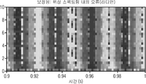
도 17은 시간-주파수 표현 내의 직접적인 카피-업 SBR을 사용하여 QMF 도메인 내의 바이올린 신호의 PDT 내의 평활 오류를 도시한다.
도 18a는 시간-주파수 표현 내의 보정된 SBR을 위하여 QMF 도메인 내의 바이올린 신호의 PDT 내의 평활 오류를 도시한다.
도 18b는 도 18a에 도시된 오류와 상응하는 시간에 대한 위상 유도를 도시한다.
도 19는 디코더의 개략적인 블록 다이어그램을 도시한다.
도 20은 인코더의 개략적인 블록 다이어그램을 도시한다.
도 21은 오디오 신호일 수 있는 데이터 스트림의 개략적인 블록 다이어그램을 도시한다.
도 22는 또 다른 실시 예에 따른 도 21의 데이터 스트림을 도시한다.
도 23은 오디오 신호의 처리를 위한 방법의 개략적인 블록 다이어그램을 도시한다.
도 24는 오디오 신호의 인코딩을 위한 방법의 개략적인 블록 다이어그램을 도시한다.
도 25는 오디오 신호의 디코딩을 위한 방법의 개략적인 블록 다이어그램을 도시한다.
도 26은 또 다른 실시 예에 따른 오디오 프로세서의 개략적인 블록 다이어그램을 도시한다.
도 227은 바람직한 실시 예에 따른 오디오 프로세서의 개략적인 블록 다이어그램을 도시한다.
도 28a는 신호 흐름을 나타내는 오디오 프로세서 내의 위상 보정의 개략적인 블록 다이어그램을 더 상세히 도시한다.
도 28b는 도 26-28a와의 또 다른 비교 관점으로부터의 위상 보정의 단계들을 도시한다.
도 29는 표적 위상 측정 결정기를 나타내는 오디오 프로세서 내의 표적 위상 측정 결정기의 개략적인 블록 다이어그램을 더 상세히 도시한다.
도 30은 표적 위상 측정 발생기를 나타내는 오디오 프로세서 내의 표적 위상 측정 발생기의 개략적인 블록 다이어그램을 더 상세히 도시한다.
도 31은 디코더의 개략적인 블록 다이어그램을 도시한다.
도 32는 인코더의 개략적인 블록 다이어그램을 도시한다.
도 33은 오디오 신호일 수 있는 데이터 스트림의 개략적인 블록 다이어그램을 도시한다.
도 34는 오디오 신호의 처리를 위한 방법의 개략적인 블록 다이어그램을 도시한다.
도 35는 오디오 신호의 디코딩을 위한 방법의 개략적인 블록 다이어그램을 도시한다.
도 36은 신호의 디코딩을 위한 방법의 개략적인 블록 다이어그램을 도시한다.
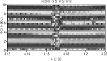
도 37은 시간-주파수 표현 내의 직접적인 카피-업 SBR을 사용하여 QNF 도메인 내의 트럼본 신호의 위상 스펙트럼 내의 오류를 도시한다.
도 38a는 시간-주파수 표현 내의 보정된 SBR을 사용하여 QNF 도메인 내의 트럼본 신호의 위상 스펙트럼 내의 오류를 도시한다.
도 38b는 도 38a에 도시된 오류와 상응하는 주파수에 대한 위상 유도를 도시한다.
도 39는 계산기의 개략적인 블록 다이어그램을 도시한다.
도 40은 변이 결정기 내의 신호 흐름을 나타내는 계산기의 개략적인 블록 다이어그램을 도 상세히 도시한다.
도 41은 또 다른 실시 예에 따른 계산기의 개략적인 블록 다이어그램을 도시한다.
도 42는 오디오 신호를 위한 위상 보정 데이터의 결정을 위한 방법의 개략적인 블록 다이어그램을 도시한다.
도 43a는 시간-주파수 표현 내의 QMF 도메인 내의 바이올린 신호의 시간에 대한 위상 유도의 표준 편차를 도시한다.
43b는 43a와 관련하여 도시된 시간에 대한 위상 유도와의 표준 편차와 상응하는 주파수에 대한 위상 유도의 표준 편차를 도시한다.
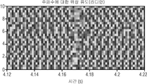
도 43c는 시간-주파수 표현 내의 QMF 도메인 내의 트럼본 신호의 시간에 대한 위상 유도의 표준 편차를 도시한다.
도 43d는 43c와 관련하여 도시된 시간에 대한 위상 유도와의 표준 편차와 상응하는 주파수에 대한 위상 유도의 표준 편차를 도시한다.
도 44a는 시간-주파수 표현 내의 QMF 도메인 내의 바이올린 + 클랩 신호의 크기를 도시한다.
도 44b는 도 44a에 도시된 크기 스펙트럼과 상응하는 위상 스펙트럼을 도시한다.
도 45a는 시간-주파수 표현 내의 QMF 도메인 내의 바이올린 + 클랩 신호의 시간에 대한 위상 유도를 도시한다.
도 45b는 도 44a에 도시된 시간에 대한 위상 유도와 상응하는 주파수에 대한 위상 유도를 도시한다.
도 46a는 시간-주파수 표현 내의 QMF 도메인 내의 바이올린 + 클랩 신호의 시간에 대한 위상 유도를 도시한다.
도 46b는 도 46a에 도시된 시간에 대한 위상 유도와 상응하는 주파수에 대한 위상 유도를 도시한다.
도 47은 시간-주파수 표현 내의 QMF 대역들의 주파수들을 도시한다.
도 48a는 ㅅ;긴-주파수 표현 내에 도시된 원래 주파수들과 비교하여 직접적인 카피-업 SBR을 사용하는 QMF 대역들의 주파수들을 도시한다.
도 48b는 시간-주파수 표현 내의 원래 주파수들과 비교하여 보정된 SBR을 사용하는 QMF의 주파수들을 도시한다.
도 49는 시간-주파수 표현 내의 원래 신호의 QMF 대역들의 주파수들과 비교되는 고조파들의 추정된 주파수들을 도시한다.
도 50a는 시간-주파수 표현 내의 압축 보정 데이터로 보정된 SBR을 사용하여 QMF 도메인 내의 바이올린 신호의 시간에 대한 위상 유도를 도시한다.
도 50b는 도 50a에 도시된 시간에 대한 위상 유도의 오류와 상응하는 시간에 대한 위상 유도를 도시한다.
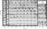
도 51a는 시간 다이어그램에서의 트럼본 신호의 파형을 도시한다.
도 52b는 단지 추정된 피크들만을 포함하는 도 51의 트럼본 신호와 상응하는 시간 도메인 신호를 도시하며, 피크들의 위치들은 전송된 메타데이터를 사용하였다.
도 52a는 시산-주파수 표현 내의 압축 보정 데이터로 보정된 SBR을 사용하여 QMF 도메인 내의 트럼본 신호의 위상 스펙트럼 내의 오류를 도시한다.
도 52b는 도 52a에 도시된 위상 스펙트럼 내의 오류와 상응하는 주파수에 대한 위상 유도를 도시한다.
도 53은 디코더의 개략적인 블록 다이어그램을 도시한다.
도 54는 바람직한 실시 예에 따른 개략적인 블록 다이어그램을 도시한다.
도 55는 또 다른 실시 예에 따른 디코더의 개략적인 블록 다이어그램을 도시한다.
도 56은 인코더의 개략적인 블록 다이어그램을 도시한다.
도 57은 도 56에 도시된 인코더에서 사용될 수 있는 계산기의 블록 다이어그램을 도시한다.
도 58은 오디오 신호의 디코딩을 위한 방법의 개략적인 블록 다이어그램을 도시한다.
도 59는 오디오 신호의 인코딩을 위한 방법의 개략적인 블록 다이어그램을 도시한다.Embodiments of the present invention will be described with reference to the accompanying drawings.
1A shows a magnitude spectrum of a violin signal in a time frequency representation.
FIG. 1B shows the phase spectrum corresponding to the magnitude spectrum of FIG. 1A.
Figure 1c
Lt; / RTI > shows the magnitude spectrum of the trombone signal within the QMF domain within the time frequency representation.
FIG. 1D shows the phase spectrum corresponding to the magnitude spectrum of FIG. 1C.
Figure 2 shows a time frequency diagram including time frequency tiles (e.g., QMF bins) defined by a time frame and a subband.
Figure 3A shows a preferred frequency diagram of an audio signal, and the magnitude of the frequency is shown for ten different subbands.
Figure 3b shows a preferred principal representation of the audio signal after the acceptance, i. E. During the decoding process, in the intermediate stage.
3C shows a preferred frequency representation of the reconstructed audio signal Z (k, n).
4A shows the magnitude spectrum of the violin in the QMF domain using a direct copy-up SBR in the time-frequency representation.
FIG. 4B shows the phase spectrum corresponding to the magnitude spectrum of FIG. 4A.
Figure 4c shows the magnitude spectrum of the trombone signal in the QMF domain using a positive copy-up SBR in the time-frequency representation.
Figure 4d shows the phase spectrum corresponding to the magnitude spectrum of Figure 4c.
Figure 5 shows a time-domain representation of a single QMF bin with different phase values.
FIG. 6 shows a time-domain and frequency-domain representation with one non-zero frequency band and a phase value to a fault value,? / 4 (top) and 3? / 4.
Figure 7 shows a time-domain and frequency-domain representation of a signal with one non-zero frequency band and with a randomly varying phase.
Fig. 8 shows the effect described in connection with Fig. 6 within the time frequency representation of four frequency sub-bands including four time frames and only the third sub-band including frequencies different from zero.
Figure 9 shows a time-domain and frequency-domain representation of a signal with one non-zero time frame and a phase having a fault value, [pi] / 4 (top) and a phase change of 3 [pi] / 4.
Figure 10 shows a time-domain and frequency-domain representation of a signal with one non-zero time frame and with a randomly varying phase.
Fig. 11 shows a time frequency domain similar to the time frequency diagram shown in Fig. 8, where only one third time frame contains frequencies other than zero.
12A shows phase induction with respect to time of a violin signal in a QMF domain in a time-frequency representation.
FIG. 12B shows the phase induction frequency corresponding to the time shown in FIG. 12A. FIG.
Figure 12C shows the phase induction with respect to time of the trombone signal within the QMF domain in the time-frequency representation.
FIG. 12D shows the phase induction frequency corresponding to the time shown in FIG. 12C. FIG.
13A shows phase derivation for the time of a violin signal in a QMF domain using a direct copy-up SBR in a time-frequency representation.
FIG. 12B shows the phase induction for the time shown in FIG. 13A and the gastric acid induction for the corresponding frequency.
13C shows the phase induction with respect to time of the trombone signal in the QMF domain using a direct copy-up SBR in the time-frequency representation.
FIG. 12D shows the phase induction for the time shown in FIG. 13C and the gastric acid induction for the corresponding frequency.
FIG. 14A schematically shows, for example, the following four time phases or frequency subbands in a unit circle.
FIG. 14B shows the phases shown in FIG. 14A after SBR processing, and the broken lines are the corrected phases.
FIG. 15 shows a schematic block diagram of an
Figure 16 also illustrates an audio processor in a schematic block diagram according to an embodiment of the present invention.
Figure 17 shows the smoothing error in the PDT of the violin signal in the QMF domain using a direct copy-up SBR in the time-frequency representation.
18A shows the smoothing error in the PDT of the violin signal in the QMF domain for the corrected SBR in the time-frequency representation.
Figure 18b shows the phase induction for the time corresponding to the error shown in Figure 18a.
Figure 19 shows a schematic block diagram of a decoder.
Figure 20 shows a schematic block diagram of an encoder.
Figure 21 shows a schematic block diagram of a data stream that may be an audio signal.
FIG. 22 shows the data stream of FIG. 21 according to another embodiment.
23 shows a schematic block diagram of a method for processing an audio signal.
24 shows a schematic block diagram of a method for encoding an audio signal.
Figure 25 shows a schematic block diagram of a method for decoding an audio signal.
26 shows a schematic block diagram of an audio processor according to another embodiment.
Figure 227 shows a schematic block diagram of an audio processor according to a preferred embodiment.
28A shows in greater detail a schematic block diagram of phase correction in an audio processor representing a signal flow.
Figure 28B shows the steps of phase correction from yet another comparison point with Figures 26-28a.
Figure 29 illustrates in greater detail a schematic block diagram of a target phase measurement determiner in an audio processor representing a target phase measurement determiner.
Figure 30 illustrates in greater detail a schematic block diagram of a target phase measurement generator in an audio processor representing a target phase measurement generator.
Figure 31 shows a schematic block diagram of a decoder.
Figure 32 shows a schematic block diagram of an encoder.
Figure 33 shows a schematic block diagram of a data stream that may be an audio signal.
Figure 34 shows a schematic block diagram of a method for processing an audio signal.
35 shows a schematic block diagram of a method for decoding an audio signal.
Figure 36 shows a schematic block diagram of a method for decoding a signal.
37 shows an error in the phase spectrum of the trombone signal in the QNF domain using a direct copy-up SBR in the time-frequency representation.
Figure 38A illustrates an error in the phase spectrum of the trombone signal within the QNF domain using the corrected SBR in the time-frequency representation.
Figure 38b shows the phase induction for the frequency corresponding to the error shown in Figure 38a.
Figure 39 shows a schematic block diagram of a calculator.
Figure 40 also shows in detail a schematic block diagram of a calculator showing the signal flow in the variator.
41 shows a schematic block diagram of a calculator according to another embodiment.
Figure 42 shows a schematic block diagram of a method for determining phase correction data for an audio signal.
43A shows the standard deviation of phase induction over time of the violin signal in the QMF domain in the time-frequency representation.
43b shows the standard deviation of the phase induction for the time shown with respect to 43a and the standard deviation of the phase induction for the corresponding frequency.
43C shows the standard deviation of the phase induction over time of the trombone signal within the QMF domain in the time-frequency representation.
Figure 43d shows the standard deviation of the phase derivation for the time shown with respect to 43c and the standard deviation of the phase derivation for the corresponding frequency.
Figure 44A shows the magnitude of the violin + clap signal in the QMF domain in the time-frequency representation.
Figure 44B shows the phase spectrum corresponding to the magnitude spectrum shown in Figure 44A.
45A shows phase induction with respect to time of the violin + clap signal in the QMF domain in the time-frequency representation.
45B shows the phase induction for the time shown in FIG. 44A and the phase induction for the corresponding frequency.
46A shows phase induction with respect to time of a violin + clap signal in a QMF domain in a time-frequency representation.
FIG. 46B shows the phase induction for the time shown in FIG. 46A and the phase induction for the corresponding frequency.
Figure 47 shows the frequencies of the QMF bands in the time-frequency representation.
48A shows the frequencies of the QMF bands using a direct copy-up SBR in comparison to the original frequencies shown in the g; long-frequency representation.
Figure 48B shows the frequencies of the QMF using the corrected SBR compared to the original frequencies in the time-frequency representation.
Figure 49 shows the estimated frequencies of harmonics compared to the frequencies of the QMF bands of the original signal in the time-frequency representation.
50A shows phase derivation for the time of a violin signal in a QMF domain using SBR corrected with compression correction data in a time-frequency representation.
FIG. 50B shows the phase induction for the time corresponding to the error of the phase induction for the time shown in FIG. 50A.
Figure 51A shows the waveform of the trombone signal in the time diagram.
FIG. 52B shows the time domain signal corresponding to the trombone signal of FIG. 51 including only estimated peaks, and the locations of the peaks used the transmitted metadata.
Figure 52A illustrates an error in the phase spectrum of the trombone signal within the QMF domain using SBR corrected with compression correction data in the estimate-frequency representation.
FIG. 52B shows the phase induction for the frequency corresponding to the error in the phase spectrum shown in FIG. 52A.
Figure 53 shows a schematic block diagram of a decoder.
54 shows a schematic block diagram according to a preferred embodiment.
55 shows a schematic block diagram of a decoder according to another embodiment.
Figure 56 shows a schematic block diagram of an encoder.
Figure 57 shows a block diagram of a calculator that can be used in the encoder shown in Figure 56;
Figure 58 shows a schematic block diagram of a method for decoding an audio signal.
Figure 59 shows a schematic block diagram of a method for encoding an audio signal.
아래에, 본 발명의 실시 예들이 더 상세히 설명될 것이다. 동일하거나 또는 유사한 기능을 갖는 각각의 도면들에 도시된 요소들은 그것들과 관련된 동일한 도면 부호들을 가질 것이다.In the following, embodiments of the present invention will be described in more detail. Elements shown in the respective figures having the same or similar function will have the same reference numerals associated with them.
본 발명의 실시 예들은 특정 신호 처리와 관련하셔 설명될 것이다. 따라서, 도-14는 오디오 신호에 적용되는 신호 처리를 설명한다. 스펙트럼 신호 처리와 관련하여 실시 예들이 설명되더라도, 본 발명은 이러한 처리에 한정되지 않고 도한 많은 다른 처리 전략들에 더 적용될 수 있다. 게다가, 도 15-25는 오디오 신호의 수직 위상 보정을 위하여 사용될 수 있는 오디오 프로세서의 실시 예들을 도시한다. 도 26-38은 오디오 신호의 수직 위상 보정을 위하여 사용될 수 있는 오디오 프로세서의 실시 예들을 도시한다. 게다가, 도 38-52는 오디오 신호를 위한 위상 보정 데이터를 결정하기 위한 계산기의 실시 예들을 도시한다. 계산기는 오디오 신호를 분석하고 이전에 언급된 오디오 프로세서들 중 어느 것이 적용되는지, 또는 오디오 신호에 어떠한 오디오 프로세서들도 적용하지 않도록 오디오 신호에 어떠한 것도 적합하지 않은지를 결정한다. 도 53-59는 제 2 프로세서 및 계산기를 포함할 수 있는 디코더 및 인코더의 실시 예들을 도시한다.Embodiments of the present invention will be described with reference to specific signal processing. Therefore, Fig. 14 illustrates signal processing applied to an audio signal. Although embodiments have been described with respect to spectral signal processing, the present invention is not limited to such processing and may be further applied to many other processing strategies. In addition, Figures 15-25 illustrate embodiments of an audio processor that may be used for vertical phase correction of an audio signal. Figs. 26-38 illustrate embodiments of an audio processor that may be used for vertical phase correction of an audio signal. In addition, Figures 38-52 illustrate embodiments of a calculator for determining phase correction data for an audio signal. The calculator analyzes the audio signal and determines whether any of the previously mentioned audio processors are applied, or that none of the audio signals are suitable to not apply any audio processors to the audio signal. Figures 53-59 illustrate embodiments of a decoder and encoder that may include a second processor and a calculator.
도입Introduction
지각적 오디오 코딩은 제한된 용량을 갖는 전송 또는 저장 채널들을 사용하여 소비자들에 오디오와 멀티미디어를 제공하는 모든 형태의 적용을 위한 디지털 기술을 가능하게 하는 메인스트림(mainstream)으로서 확산되어왔다. 현대 지각적 오디오 코덱들은 등가하는 낮은 비트 레이트들에서 만족한 오디오 품질을 전달할 필요가 있다. 차례로, 대부분의 청취자들에 의해 가장 견딜 수 있는 특정 코딩 아티책트들을 견뎌야만 한다. 오디오 대역폭 확장(BWE)은 스펙트럼 이동 또는 특정 아티팩트들의 도입을 희생하고 전송된 저대역 신호 부분들의 고대역 내로의 전이에 의해 오디오 코더의 주파수 범위를 인공적으로 확장하는 기술이다.Perceptual audio coding has spread as a mainstream enabling digital technology for all types of applications that provide audio and multimedia to consumers using transmission or storage channels with limited capacity. Modern perceptual audio codecs need to deliver satisfactory audio quality at equivalent low bit rates. In turn, it must endure certain coding artifacts that are most tolerable by most listeners. Audio bandwidth extension (BWE) is a technique that artificially extends the frequency range of an audio coder by transferring the transmitted low band signal portions into the high band at the expense of spectral shift or introduction of specific artifacts.
발견은 이러한 아티팩트들이 인공적으로 확장된 고대역 내의 위상 유도의 변화와 관련된다는 것이다. 이러한 아티팩트들 중의 하나는 주파수에 대한 위상 유도의 변경(또한 "수직" 위상 간섭 참조)이다[8].상기 위상 유도의 보존은 시간 도메인 파형 및 오히려 낮은 기본 주파수 같은 펄스-트레인을 갖는 음조 신호들을 이하여 지각적으로 중요하다. 수직 위상 유도의 변화와 관련된 아티팩트들은 시간 내의 에너지의 국소 분산(local dispersion)과 상응하고 흔히 BWE 기술들에 의해 처리된 오디오 신호들에서 발견된다. 또 다른 아티팩트는 어떤 기본 주파수의 배음(overtone)이 풍부한 음조 신호들을 위하여 지각적으로 중요한 시간에 대한 위상 유도의 변경(또한 "수평" 위상 간섭 참조)이다. 수평 위상 유도의 변경과 관련된 sdkxlvorxm들은 피치 내의 국소 주파수 오프셋과 상응하고 흔히 BWE 기술들에 의해 처리된 오디오 신호들에서 발견된다.The discovery is that these artifacts are associated with changes in phase induction in artificially extended high bands. One of these artifacts is the change of phase induction to frequency (also referred to as "vertical" phase interference) [8]. The preservation of the phase induction results in the generation of tonal signals having pulse-trains such as a time domain waveform and a rather low fundamental frequency It is perceptually important. Artifacts associated with changes in vertical phase induction correspond to local dispersion of energy in time and are often found in audio signals processed by BWE techniques. Another artifact is the change in phase induction (also referred to as "horizontal" phase interference) for the perceptually significant time for tonal signals rich in overtones of some fundamental frequency. The sdkxlvorxm associated with a change in the horizontal phase induction corresponds to the local frequency offset in the pitch and is often found in audio signals processed by BWE techniques.
본 발명은 이러한 특성이 이른바 오디오 대역폭 확장(BWE)의 적용에 의해 절충될 때 그러한 신호들의 수직 또는 수평 위상 유도를 재보정하기 위한 수단들을 제시한다. 위상 유도의 회복이 지각적으로 유익한지 그리고 수직 또는 수평 위상 유도의 보정이 지각적으로 바람직한지를 결정하기 위한 또 다른 수단들이 제시된다.The present invention suggests means for recalibrating the vertical or horizontal phase induction of such signals when such characteristics are compromised by the application of so-called audio bandwidth extension (BWE). Other means are provided to determine if the recovery of phase induction is perceptually beneficial and whether correction of vertical or horizontal phase induction is perceptually desirable.
스펙트럼 대역 복제(SBR)[9]와 같은, 대역폭 확장 방법들은 흔히 낮은 비트 레이트 코덱들로서 사용된다. 그것들은 높은 대역들에 관한 파라미터 정보와 함께 상대적으로 좁은 저주파수 영역의 전송만을 허용한다. 파라미터 정보의 비트 레이트가 작기 때문에, 코딩 효율에서의 상당한 향상이 획득될 수 있다.Bandwidth extension methods, such as spectral band replication (SBR) [9], are often used as low bit rate codecs. They allow transmission only in relatively low frequency regions with parameter information about high bands. Since the bit rate of the parameter information is small, a significant improvement in coding efficiency can be obtained.
일반적으로 높은 대역들을 위한 신호는 단순하게 전송된 저주파수 영역으로부터 이를 복사함으로써 획득된다. 처리는 일반적으로 또한 아래에서 추정되는, 복합 변조 직각 대칭 필터 뱅크(QMF)[10] 도메인에서 실행된다. 카피-업 신호는 전송된 파라미터들을 기초로 하여 그것의 크기 스펙트럼에 적절한 이득들을 곱함으로써 처리된다. 목적은 원래 신호와 유사한 크기 스펙트럼을 획득하는 것이다. 이와 반대로, 카피-업 신호의 위상 스펙트럼은 일반적으로 전혀 처리되지 않으나, 대신에, 카피-업 위상 스펙트럼이 직접적으로 사용된다.In general, the signals for high bands are obtained by simply copying them from the transmitted low frequency region. The processing is generally performed in a complex-modulated right-angled symmetric filter bank (QMF) [10] domain, also estimated below. The copy-up signal is processed by multiplying its magnitude spectrum by the appropriate gains based on the transmitted parameters. The goal is to obtain a magnitude spectrum similar to the original signal. Conversely, the phase spectrum of the copy-up signal is generally not processed at all, but instead, the copy-up phase spectrum is directly used.
커피-업 위상 스펙트럼의 직접적인 사용의 지각적 결과는 아래에서 설명된다. 관찰된 효과들을 기초로 하여, 지각적으로 가장 중요한 효과들을 검출하기 위한 매트릭스들이 제안된다. 게다가, 그것들을 기초로 하여 위상 스펙트럼을 보정하는 방법들이 제안된다. 최종적으로, 보정을 실행하기 위하여 전송된 파라미터 값들의 양을 최소화하기 위한 전략들이 제안된다.Perceptual results of the direct use of the coffee-up phase spectrum are described below. Based on the observed effects, matrices are proposed for detecting perceptually most significant effects. In addition, methods for correcting the phase spectrum based on them are proposed. Finally, strategies are proposed to minimize the amount of parameter values sent to perform the correction.
본 발명은 위상 유도의 보존 또는 복원이 오디오 대역폭 확장(BWE) 기술들에 의해 도입되는 중요한 아티팩트들을 처리할 수 있다는 발견과 관련된다. 예를 들면, 위상 유도의 보존이 중요한, 일반적인 신호들은 유성 음성(voiced speech), 금관 악기 또는 찰현악기(bowed string)들과 같은, 풍부한 고조파 배음 콘텐츠를 갖는 톤들이다.The present invention relates to the discovery that the preservation or restoration of phase induction can handle significant artifacts introduced by audio bandwidth extension (BWE) techniques. For example, typical signals for which phase preservation is important are tones with abundant harmonic overtone content, such as voiced speech, brass or bowed strings.
본 발명은 주어진 신호 프레임을 위하여, 위상 유도의 복원이 지각적으로 유익한지 그리고 수직 또는 수평 위상 유도의 보정이 지각적으로 바람직한지를 결정하기 위한 수단들을 더 제공한다.The present invention further provides means for determining, for a given signal frame, whether the reconstruction of the phase induction is perceptually beneficial and the correction of the vertical or horizontal phase induction is perceptually desirable.
본 발명은 아래의 양상들을 갖는 BWE 기술들을 사용하여 오디오 코덱들 내의 위상 유도 보정을 위한 장치 및 방법을 설명한다.The present invention describes an apparatus and method for phase-induced correction in audio codecs using BWE techniques with the following aspects.
1. 위상 유도 보정의 "중요성"의 정량화1. Quantification of the "importance" of phase-induced correction
2. 수직)"주파수") 위상 유도 보정 또는 수평("시간") 위상 유도 보정의 신호 의존적 우성순위2. Vertical) "Frequency") Signal-dependent dominance of phase-induced correction or horizontal ("time") phase-
3, 보정 방향("주파수" 또는 "시간")의 신호 의존적 스위칭3, signal dependent switching of the correction direction ("frequency" or "time &
4. 트랜지언트들을 위한 전용 수직 위상 유도 보정4. Dedicated vertical phase induction compensation for transients
5. 평활 보정을 위한 안정적인 파라미터들의 획득5. Obtaining stable parameters for smoothing correction
6. 보정 파라미터들의 간결한 부가 정보 전송 포맷6. Simplified supplementary information transmission format of calibration parameters
2. QMF 도메인 내의 신호들의 보존2. Preserving signals in the QMF domain
m이 개별 시간인, 시간 도메인 신호(x(m))는 예를 들면 복합 변조 직각 대칭 필터 뱅크(WMF)를 사용하여, 시간-주파수 도메인 내에 나타낼 수 있다. 결과로서 생긴 신호는 X(k,n)이고, 여기서 k는 주파수 대역 지수이고 n은 시간 프레임 지수이다. 시각화들과 실시 예들을 위하여 64 대역의 QMF 및 48㎑의 샘플링 주파수가 추정된다. 따라서, 각각의 주파수 대역의 대역폭(fBW)은 375㎐이고 시간적 홉 크기(hop size, thop, 도 2에서의 17)는 1.44ms이다. 그러나, 처리는 그러한 변환에 한정되지 않는다. 대안으로서, MDCT(변형 이산 코사인 변환) 또는 DFT(이산 푸리에 변환)이 대신에 사용될 수 있다.The time domain signal x (m), where m is a discrete time, can be represented in the time-frequency domain, for example, using a complex modulated right-angled symmetric filter bank WMF. The resulting signal is X (k, n), where k is the frequency band index and n is the time frame index. 64 bits of QMF and 48 kHz sampling frequency are estimated for visualizations and embodiments. Therefore, the bandwidth (f BW ) of each frequency band is 375 Hz and the temporal hop size (hop size, t hop , 17 in Fig. 2) is 1.44 ms. However, the processing is not limited to such a conversion. As an alternative, MDCT (Modified Discrete Cosine Transform) or DFT (Discrete Fourier Transform) may be used instead.
결과로서 생긴 신호는 X(k, n)이고, 여기서 k는 주파수 대역 지수이고 n은 시간적 프레임 지수이다. X(k,n)은 복합 신호이다. 따라서,이는 또한 j가 복소수인 크기(Xmag(k,n) 및 위상 성분들(Xpha(k,n)을 사용하여 나타낼 수 있다The resulting signal is X (k, n), where k is the frequency band index and n is the temporal frame index. X (k, n) is a composite signal. Thus, it can also be represented using the magnitude (X mag (k, n) and phase components X pha (k, n) where j is a complex number
![]()
![]()
오디오 신호들은 대부분 Xmag(k,n) 및 Xpha(k,n)을 사용하여 나타낸다(두 예를 위하여 도 1 참조).Audio signals are mostly represented using X mag (k, n) and X pha (k, n) (see Figure 1 for both examples).
도 1a는 바이올린 신호의 크기 스펙트럼(Xmag(k,n))을 도시하며, 도 1b는 QMF 도메인 모두 내의 상응하는 위상 스펙트럼(Xpha(k,n))을 도시한다. 게다가, 도 1c는 Figure 1a shows the magnitude spectrum of violin signals (X mag (k, n) ) , and Figure 1b shows the corresponding phase spectrum (Xp ha (k, n) ) for all in a QMF domain. In addition,
트럼본 trls호의 크기 스펙트럼(Xmag(k,n))을 도시하며, 도 1d는 상응하는 QMF 도메인 내의 상응하는 위상 스펙트럼(Xpha(k,n))을 도시한다. 도 1a 및 1c의 크기 스펙트럼과 관련하여, 색 구배는 적색 = 0dB부터 청색 = -80dB까지의 크기를 나타낸다. 게다가, 도 1b 및 1d에서의 위상 스펙트럼을 위하여, 색 구배는 적색 = π무터 청색 = -π까지의 위상들을 나타낸다.Showing the trombone heading trls size spectrum (X mag (k, n) ) , and Figure 1d shows the corresponding phase spectrum (Xp ha (k, n) ) , which in the corresponding QMF domain. With respect to the magnitude spectrum of FIGS. 1A and 1C, the color gradient represents the size from red = 0 dB to blue = -80 dB. In addition, for the phase spectra in Figures 1B and 1D, the color gradient represents the phases up to red = [pi] muter blue = - [pi].
3. 오디오 데이터3. Audio data
설명된 오디오 처리의 효과를 나타내도록 사용되는 오디오 데이터는 트럼본의 오디오 신호에 대하여 '트롬본', 바이올린의 오디오 신호를 위하여 '바이올린, 그리고 중간에 첨가되는 박수(hand clap)를 갖는 신호를 위하여 "바이올린+클랩"으로 명명된다.The audio data used to represent the effects of the described audio processing may include a "trombone" for the audio signal of the trombone, a "violin" for the violin's audio signal, a "violin" for the signal having the middle clap + CLAP ".
4. SBR의 기본 연산4. Basic operation of SBR
도 2는 시간 프레임(15) 및 부대역(20)에 의해 정의되는, 시간 주파수 타일들(10, 예를 들면 직각 대칭 필터 뱅크 빈들)을 포함하는 시간 주파수 다이어그램(5)을 도시한다. 오디오 신호는 QMF(직각 대칭 필터 뱅크) 변환, MDCT(변형 이산 코사인 변환), 또는 DFT(이산 푸리에 변환)를 사용하여 그러한 시간 주파수 표현으로 변환될 수 있다. 시간 프레임들 내의 오디오 신호의 세분은 오디오 신호의 오버래핑 부분들을 포함할 수 있다. 도 1의 하부 부분에서, 시간 프레임들(15)의 단일 오버랩이 도시되며, 최대 두 개의 시간 프레임에서 동시에 오버랩한다. 게다가, 만일 더 많은 중복이 필요하면, 오디오 신호는 또한 다중 오버랩을 사용하여 세분될 수 있다. 다중 오버랩 알고리즘에서 3개 이상의 시간 프레임은 특정 시간 지점에서 오디오 신호의 동일한 부분을 포함할 수 있다. 오버랩의 기간은 홉 크기(thop, 17)이다.Figure 2 shows a time frequency diagram 5 including time frequency tiles 10 (e.g., rectangularly symmetric filter bank bins), defined by a
신호(X(k,n)), 대역폭 확장된(BWE) 신호(Z(k,n)가 전송된 저주파수 주파수 대역의 특정 부분들을 카피-업함으로써 입력 신호(X(k,n))로부터 획득되는 것을 가정한다. sbr 알고리즘은 전송되려는 주파수 영역의 선택에 의해 시작한다. 이러한 예에서, 1부터 7까지의 대역들이 선택된다.From the input signal X (k, n) by copying up the specific portions of the low frequency frequency band to which the signal X (k, n) and the bandwidth extended (BWE) signal Z (k, n) The sbr algorithm starts with the selection of the frequency domain to be transmitted. In this example,
![]()
![]()
전송되려는 주파수 대역들의 양은 원하는 비트 레이트에 의존한다. 도면들과 방정식들은 7개의 대역을 사용하여 생산되고, 상응하는 오디오 데이터를 위하여 5 내지 11개의 대역의 형성이 사용된다. 따라서, 전송된 주파수 영역 및 고대역들 사이의 교파 주파수들은 각각 1875부터 4125㎐까지이다. 이러한 영역 위의 주파수 대역들은 전혀 전송되지 않으나, 대신에, 그것들의 성명을 위하여 파라미터 메타데이터가 생성된다. 또 다른 처리가 가정된 경우에 한정되지 않는다는 것이 알려져야만 하더라도, xTRANS(K,N)은 어떠한 방법으로도 신호를 변형하지 않는다.The amount of frequency bands to be transmitted depends on the desired bit rate. The figures and equations are produced using seven bands and the formation of five to eleven bands is used for the corresponding audio data. Thus, the denominator frequencies between the transmitted frequency domain and the high bands are respectively from 1875 to 4125 Hz. The frequency bands on this area are not transmitted at all, but instead, the parameter metadata is generated for their statement. X TRANS (K, N) does not transform the signal in any way, although it should be known that other processing is not limited to the case where it is assumed.
수용 목적으로, 전송된 주파수 영역은 상응하는 주파수들을 위하여 직접적으로 사용된다.For acceptance purposes, the transmitted frequency domain is used directly for the corresponding frequencies.
고대역들을 위하여, 신호는 전송된 신호를 사용하여 다소 생성될 수 있다. 한 가지 접근법은 단순하게 던송된 신호를 고주파수들에 복사하는 것이다. 약간 변형된 버전이 여기서 사용된다. 먼저, 기저대역 신호가 선택된다. 이는 전체 전송된 신호일 수 있으나, 본 실시 예에서 제 1 주파수 대역은 생략된다. 이러한 이유는 위상 스펙트럼이 많은 경우들에서 제 1 대역을 위하여 불규칙적인 것으로 인식되었기 때문이다. 따라서, 카피 업되려는 기저대역은 다음과 같이 정의된다:For high bands, the signal may be somewhat generated using the transmitted signal. One approach is to simply copy the dunted signal to the higher frequencies. A slightly modified version is used here. First, the baseband signal is selected. This may be the entire transmitted signal, but in this embodiment the first frequency band is omitted. This is because the phase spectrum is recognized as being irregular for the first band in many cases. Thus, the baseband to be copied up is defined as:
![]()
![]()
다른 대역폭들이 또한 전송되고 기저대역 신호들을 위하여 사용될 수 있다. 기저대역 신호를 사용하여, 고주파수들을 위한 원시(raw) 신호들이 생성되며:Other bandwidths may also be transmitted and used for the baseband signals. Using the baseband signal, raw signals for high frequencies are generated: < RTI ID = 0.0 >
![]()
![]()
여기서 Yraw(k,n,i)는 주파수 피치(i)를 위한 복합 QMF 시호이다. 원시 주파수-피치 신호들은 그것들을 이득들(g(k,n,i)에 곱함으로써 전송된 메타데이터에 따라 조작된다:Where Yraw (k, n, i) is a complex QMF sequence for frequency pitch (i). The raw frequency-pitch signals are manipulated according to the transmitted metadata by multiplying them by the gains g (k, n, i): < EMI ID =
![]()
![]()
이득들은 실수 값들리며 따라서, 크기 스펙트럼은 영향을 받고 이에 의해 원하는 표적 값에 적응된다는 것을 이해하여야 한다. 알려진 접근법들은 어떻게 이득들이 획득되는지를 나타낸다. 표적 위상은 상기 알려진 접근법들에서 보정되지 않은 채로 남아있다.It should be appreciated that the gains are real and thus the magnitude spectrum is affected and thereby adapted to the desired target value. Known approaches show how gains are obtained. The target phase remains uncorrected in the known approaches.
재생되려는 최종 신호는 원하는 대역폭의 BWE 신호를 획득하도록 대역폭을 균일하게(seamlessly) 확장하기 위한 전송된 패치 신호들의 연결(concatenating)에 의해 획득된다.The final signal to be reproduced is obtained by concatenating the transmitted patch signals to expand the bandwidth seamlessly to obtain the BWE signal of the desired bandwidth.

도 3은 그래픽 표현에서 설명된 신호들을 도시한다. 도 3a는 오디오 신호의 바람직한 주파수 다이어그램을 도시하며, 상이한 부대역들에 대하여 주파수의 크기가 도시된다. 첫 번째 7개의 부대역은 전송된 주파수 대역들(Xtrans(k,n), 25)을 반영한다. 기저대역(Xbase(k,n), 30)은 7개의 부대역 다음의 선택에 의해 그것으로부터 유도된다. 도 3b는 예를 들면 중간 단계에서 디코딩 과정 동안에, 수용 이후의 오디오 신호의 바람직한 주파수 표현을 도시한다. 오디오 신호의 주파수 스펙트럼은 전송된 주파수 대역들(25) 및 기저대역 내의 주파수들보다 높은 주파수들을 포함하는 오디오 신호(32)를 형성하는 주파수 스펙트럼의 높은 부대역들에 복사되는 7개의 기저대역 신호들(30)을 포함한다. 완전한 기저대역 신호는 또한 주파수 패치로서 언급된다. 도 3c는 재구성된 오디오 신호(Z(k,n), 35)를 도시한다. 도 3b와 비교하여, 기저대역 신호들의 패치들은 개별적으로 이득 인자에 의해 곱해진다. 따라서, 오디오 신호의 주파수 스펙트럼은 주 주파수 스펙트럼(25) 및 다수의 크기 보정된 패치들(Y(k,n), 40)을 포함한다. 이러한 패칭 방법은 직접적인 카피-업 패칭으로서 언급된다. 직접적인 카피-업 패칭은 비록 본 발명이 그러한 패칭 알고리즘에 한정되지 않더라도, 바람직하게는 본 발명을 설명하도록 사용된다. 사용될 수 있는 또 다른 패칭 알고리즘은 예를 들면, 고조파 패칭 알고리즘이다.Figure 3 shows the signals described in the graphical representation. Figure 3A shows a preferred frequency diagram of an audio signal, the magnitude of the frequency being shown for different subbands. The first seven subbands reflect the transmitted frequency bands (X trans (k, n), 25). The baseband (X base (k, n), 30) is derived from it by a choice of seven subbands. FIG. 3B shows a preferred frequency representation of the audio signal after receipt, for example during a decoding process in an intermediate step. The frequency spectrum of the audio signal includes seven baseband signals that are copied to the higher subbands of the frequency spectrum forming the
고대역들의 파라미터 표현이 완벽하다는 것, 즉 재구성된 신호의 크기 스펙트럼이 원래 신호와 동일하다는 것이 가정된다.It is assumed that the parameter representation of the high bands is perfect, i. E. The magnitude spectrum of the reconstructed signal is the same as the original signal.
![]()
![]()
그러나, 위상 스펙트럼은 알고리즘에 의해 그러한 방법으로도 보정되지 않고, 따라서 알고리즘이 완벽하게 작용된지는 정확하지 않다는 것을 이해하여야 한다. 따라서, 실시 예들은 지각적 품질의 향상이 획득되도록 표적 값에 대하여 Z(k,n)의 위상 스펙트럼을 어더ㅎ게 부가적으로 작용하고 보정하는지를 도시한다. 실시 예들에서, 보정은 세 가지 상이한 처리 모드들, "수평", "수직" 및 "트랜지언트"를 사용하여 실행될 수 있다. However, it should be appreciated that the phase spectrum is not corrected in such a way by the algorithm, and therefore it is not precise whether the algorithm is fully functional. Thus, embodiments illustrate how the phase spectrum of Z (k, n) is additionally acting and compensating for the target value, such that an enhancement in perceptual quality is obtained. In embodiments, the correction may be performed using three different processing modes, "horizontal", "vertical", and "transient".
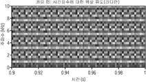
바이올린 및 트럼본 신호들을 위하여 도 4에 Zmag(k,n) 및 Zpha(k,n)이 도시된다. 도 4는 직접적인 카피-업 패칭을 갖는 스펙트럼 대역 복제(SBR)를 사용하여 재구성된 오디오 신호(35)의 바람직한 스펙트럼을 도시한다. 바이올린 신호의 크기 스펙트럼(Zmaf(k,n))이 도 4a에 도시되며, 도 4b는 상응하는 위상 스펙트럼(Zpha(k,n))을 도시한다. 도 4c 및 4d는 트럼본 신호의 상응하는 스펙트럼들을 도시한다. 모든 신호는 QMF 도메인 내에 제시된다. 도 1에서 알 수 있는 것과 같이, 색 구배는 적색 = 0dB부터 청색 = -80dB까지의 크기 및 적색 = π부터 청색 = -π까지의 위상을 나타낸다. 그것들의 위상 스펙트럼들은 원래 신호들의 위상 스펙트럼들과 다르다는 것을 알 수 있다(도 1 참조). SBR에 기인하여, 바이올린은 비조화성(inharmonicity)을 포함하고 트럼본은 교파 주파수들에서 변조 잡음들을 포함하는 것으로 지각된다. 그러나, 위상 플롯(plot)들은 상당히 임의적으로 보이고, 실제로 그것들이 얼마나 다르고 차이들의 지각적 효과들이 무엇인지를 말하는 것은 어렵다. 게다가. 이러한 종류의 임의 데이터를 위한 보정 데이터의 송신은 낮은 비트 레이트를 요구하는 코딩 적용들에서 실현 가능하지 않다. 따라서, 위상 스펙트럼의 지각적 효과들의 이해 및 그것들의 설명을 위한 매트릭스들의 발견이 필요하다. 이러한 주제들은 아래의 섹션들에서 설명된다.Z mag (k, n) and Z pha (k, n) are shown in FIG. 4 for the violin and trombone signals. Figure 4 shows the preferred spectrum of the reconstructed
5, QMF 도메인 내의 위상 스펙트럼의 의미5, meaning of phase spectrum in QMF domain
흔히 주파수 대역의 지수는 단일 음조 성분의 주파수를 정의하고, 크기는 그것의 레벨을 정의하며, 위상은 그것의 "타이밍:을 정의하는 것으로 사료된다. 그러나, QMF 대역의 대역폭은 상대적으로 크고, 데이터는 오버샘플링된다. 따라서, 시간-주파수 타일들(즉, QMF 빈들) 사이의 상호작용은 실제로 이러한 모든 특성을 정의한다.Often, the exponent of a frequency band defines the frequency of a single tone component, the size defines its level, and the phase defines its "timing." However, the bandwidth of the QMF band is relatively large, The interactions between time-frequency tiles (i.e., QMF bins) actually define all these characteristics.
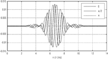
세 가지 다른 위상 값들, 즉 Xmag(3.1)=1 및 Xpha(3.1)=0,π/2, 또는 π를 갖는 단일 QMF 빈의 시간-도메인 표현이 도 5에 도시된다. 결과는 13.3ms의 길이를 갖는 사인 유사 함수이다. 함수의 정확한 형태는 위상 파라미터에 의해 정의된다.A time-domain representation of a single QMF bin with three different phase values, X mag (3.1) = 1 and X pha (3.1) = 0, π / 2, or π is shown in FIG. The result is a sine-like function with a length of 13.3 ms. The exact form of the function is defined by the phase parameter.
주파수 대역만이 시간적 프레임들을 위하여 비-제로인 것, 즉 다음을 고려하고,Only the frequency band is non-zero for temporal frames, i.
![]()
![]()
시간적 프레임들 사이의 위상을 고정 값(α)으로 변경함으로써, 득 아래와 같이 함으로써,By changing the phase between temporal frames to a fixed value [alpha], by doing the following,
![]()
![]()
사인곡선이 생성된다. 결과로서 생긴 신호(즉, 역 QMF 변환 이후의 시간-도메인 신호)가 도 6에 제시되고 α의 값들은 π/4(상단) 및 3π/4(바닥부)이다. 사인곡선의 주파수는 위상 변화에 의해 영향을 받는 것을 알 수 있다. 주파수 도메인이 오른쪽에 도시되고, 신호의 시간 도메인은 도 6의 왼쪽 상에 도시된다.A sinusoid is created. The resulting signal (i. E. Time-domain signal after inverse QMF transform) is shown in FIG. 6 and the values of alpha are pi / 4 (top) and 3 pi / 4 (bottom). It can be seen that the frequency of the sinusoid is affected by the phase change. The frequency domain is shown on the right and the time domain of the signal is shown on the left side of FIG.
상응하게, 만일 위상이 임의로 선택되면, 결과는 협대역 잡음이다(도 7 참조), 따라서, QMF 빈의 위상은 상응하는 주파수 대역 내부의 주파수 콘텐츠를 제어하고 있다고 말할 수 있다.Correspondingly, if the phase is arbitrarily selected, the result is narrowband noise (see FIG. 7), so that the phase of the QMF bean can be said to control the frequency content within the corresponding frequency band.
도 8은 4개의 시간 프레임과 4개의 색 주파수 부대역의 시간 주파수 표현 내의 도 6에 대하여 설명된 효과를 도시하며, 제 3 부대역만이 0과 다른 주파수를 포함한다. 이는 도 8의 오른쪽 상에 개략적으로 제시된, 도 6으로부터의 주파수 도메인 신호 및 도 8의 바닥부에 개략적으로 제시된 도 6의 시간 도메인 표현을 야기한다.Fig. 8 shows the effect described with respect to Fig. 6 in the time frequency representation of four time frames and four color frequency subbands, where only the third subband includes frequencies different from zero. This results in the frequency domain signal from Fig. 6 schematically presented on the right hand side of Fig. 8 and the time domain representation of Fig. 6 schematically presented at the bottom of Fig.
하나의 시간적 프레임만이 모든 주파수 대역을 위하여 비-제로인 것을 고려하고, 즉 다음과 같고,Considering that only one temporal frame is non-zero for all frequency bands, i.e.,
![]()
![]()
주파수 대역들 사이의 위상을 고정 값(α)으로 변경함으로써, 득 아래와 같이 함으로써,By changing the phase between the frequency bands to a fixed value [alpha], by doing the following,
![]()
![]()
트랜지언트가 생성된다. 결과로서 생긴 신호(즉, 역 QMF 변환 이후의 시간-도메인 신호)가 도 9에 제시되고 α의 값들은 π/4(상단) 및 3π/4(바닥부)이다. 트랜지언트의 시간적 위치는 위상 변화에 의해 영향을 받는 것을 알 수 있다. 주파수 도메인이 도 9의 오른쪽에 도시되고, 신호의 시간 도메인은 도 9의 왼쪽 상에 도시된다.A transient is generated. The resulting signal (i. E. Time-domain signal after inverse QMF transform) is shown in Figure 9 and the values of alpha are pi / 4 (top) and 3 pi / 4 (bottom). It can be seen that the temporal position of the transient is influenced by the phase change. The frequency domain is shown on the right side of Fig. 9, and the time domain of the signal is shown on the left side of Fig.
도 11은 도 8에 도시된 시간 주파수 다이어그램과 유사한 시간 주파수 도메인을 도시한다. 도 11에서, 제 3 시간 프레임만이 하나의 부대역으로부터 나머지로 π/4의 이동을 갖는 0과 다른 값들을 포함한다. 주파수 도메인으로 변환되면, 도9의 오른쪽 측으로부터 주파수 도메인 신호가 획득괴도, 도 11에 개략적으로 제시된다. 도 9의 왼쪽 부분의 개략적인 시간 도메인 표현이 도 11의 바닥부에 도시된다. 이러한 신호는 시간 주파수 모메인의 시간 도메인 신호로의 변환에 의해 야기된다.11 shows a time frequency domain similar to the time frequency diagram shown in Fig. In Fig. 11, only the third time frame contains zero and other values with a shift of pi / 4 from one subband to the rest. When converted to the frequency domain, the frequency domain signal from the right side of FIG. 9 is obtained schematically in FIG. 11. A schematic time domain representation of the left part of FIG. 9 is shown at the bottom of FIG. This signal is caused by the conversion of the time-frequency domain into a time-domain signal.
6. 위상 스펙트럼의 지각적으로 관련된 특성들의 설명을 위한 측정들6. Measurements for describing perceptually related characteristics of the phase spectrum
섹션 4에 설명된 것과 같이, 위상 스펙트럼은 스스로 상당히 지저분하게 보이고, 지갓에 대한 효과가 무엇인지를 바로 아는 것은 어렵다. 섹션 5는 QMF 도메인 내의 위상 스펙트럼의 저작에 의해 야기될 수 있는 두 가지 효과를 제시하였다: (a) 시간에 대한 일정한 위상 변화는 사인곡선을 생산하고 위상 변화의 양은 사인곡선의 주파수를 제어하고, (b) 주파수에 대한 일정한 위상 변화는 트랜지언트를 생산하고 위상 변화의 양은 트랜지언트의 시간적 위치를 제어한다.As described in
부분의 주파수 및 시간적 위치는 인간 지각에 명백하게 중요하며, 따라서 이러한 특성들의 검출이 잠재적으로 유용하다. 그것들은 시간에 대한 위상 유도(PDT)의 계산:The frequency and temporal location of the part is obviously important to the human perception, and thus the detection of these properties is potentially useful. They calculate the phase induction (PDT) over time:
![]()
![]()
및 시간에 대한 위상 유도의 계산에 의해 추정될 수 있으며:And by calculating the phase induction over time: < RTI ID = 0.0 >
![]()
![]()
Xpdt(k,n)은 주파수와 관련되고 Xpdt(k,n)은 부분의 시간적 위치와 관련된다. X pdt (k, n) is related to the frequency and X pdt (k, n) is related to the temporal position of the part.
QMF 분석(인접한 시간 프레임들의 변조들의 위상들이 트랜지언트의 위치에서 어떻게 일치하는지)의 특성들에 기인하여, 평활 곡선들을 생산하도록 시각화 과정들을 위하여 도면들에서 심지어 Xpdt(k,n)의 시간적 프레임들에 π이 첨가된다.The temporal frames of X pdt (k, n), even in the figures, for visualization procedures to produce smooth curves, due to QMF analysis (how the phases of the modulations of adjacent temporal frames match at the position of the transient) Is added.
rm 다음에 이러한 측정들이 본 발명의 예제 신호들을 위하여 어떻게 보이는지가 검사된다. 도 12는 바이올린 및 트럼본 신호들을 위한 유도들을 도시한다. 특히, 도 12a는 원래, 즉 QMF 도메인 내의 처리되지 않은, 바이올린 오디오 신호의 시간에 대한 위상 유도(Zpdt(k,n)을 도시한다. 도 12b는 각각, 트럼본 신호를 위한 시간에 대한 위상 유도 및 주파수에 대한 위상 유도를 도시한다. 색 구배는 적색 = π로부터 청색 = -π까지의 위상 값들을 나타낸다. 바이올린을 위하여, 크기 스펙트럼은 기본적으로 약 0.13초까지의 잡음(도 1 참조)이고, 따라서 유도들은 또한 시끄럽다. 약 0.13초부터 시작하여 Xpdt는 시간에 대하여 상대적으로 안정적인 값들을 갖는 것처럼 보인다. 이는 신호가 강력하고, 상대적으로 안정적인, 사인곡선들을 포함하는 것을 의미할 수 있다. 이러한 사인곡선들의 주파수들은 Xpdt 값들에 의해 결정된다. 이와 대조적으로, Xpdt 플롯은 상대적으로 시끄럽고, 따라서 이를 사용하여 바이올린을 위하여 어떠한 관련 데이터도 발견되지 않는 것처럼 보인다.After rm, it is checked how these measurements appear for the exemplary signals of the present invention. Figure 12 shows the indications for the violin and trombone signals. In particular, Figure 12A shows the phase induction (Z pdt (k, n) with respect to time of the unprocessed, violin audio signal originally in the QMF domain. Figure 12b shows the phase induction for time for the trombone signal, And phase induction for frequency. The color gradient represents the phase values from red = [pi] to blue = - [pi] For the violin, the magnitude spectrum is basically noise up to about 0.13 second (see Figure 1) Therefore, starting from about 0.13 seconds, X pdt appears to have relatively stable values with respect to time, which may mean that the signal is strong and relatively stable, including sinusoids. frequency of the curves are determined by the X pdt values. in contrast, X pdt plot is relatively noisy, and thus use it in order to violin Any relevant data also seems to be not found.
트럼본을 위하여, Xpdt는 상대적으로 시끄럽다. 이와 대조적으로, Xpdt는 모든 주파수에서 대략 동일한 값들 갖는 것처럼 보인다. 실제로, 이는 모든 고조파 성분이 트랜지언트 유사 신호를 생산하는 시간에 정렬되는 것을 의미한다. 트랜지언트들의 시간적 위치들은 Xpdt 값들에 의해 결정된다.For the trombone, X pdt is relatively noisy. By contrast, X pdt appears to have approximately the same values at all frequencies. In practice, this means that all harmonic components are aligned at the time of producing the transient similar signal. The temporal positions of the transients are determined by the X pdt values.
동일한 유도들이 또한 SBR 처리된 신호들(Z(k,n))을 위하여 계산될 수 있다(도 13 참조). 도 13a 내지 13d는 이전에 설명된 직접적인 카피-업 SBR 알고리즘의 사용에 s의해 유도되는 도 12a 내지 12d와 직접적으로 관련된다. 위상 스펙트럼이 기저대역부터 높은 패치들까지 복사되기 때문에, 주파수 패치들의 PDT들은 기저대역의 그것과 동일하다. 따라서, 바이올린을 위하여, PDT는 원래 신호의 경우에서와 같이, 안정적인 사인곡선을 생산하는 시간에 대하여 상대적으로 평활하다. 그러나, ZSpdt의 값들은 원래 신호(Xpdt)의 그것들과 다르며, 이는 생산된 사인곡선들이 원래 신호와 다른 주파수들을 갖는다는 것을 야기한다. 이의 지각적 효과는 섹션 7에 설명된다.그 결과, 주파수 패치들의 PDF는 그렇지 않으면 기저대역의 그것과 동일하나, 교차 주파수들에서 PDF는 실제로, 임의적이다. 교차에서, PDF는 실제로 주파수 패치의 마지막 및 첫 번째 위상 값 사이에서 계산되며, 즉 다음과 같다:The same inductances can also be calculated for the SBR processed signals Z (k, n) (see FIG. 13). Figures 13A-13D are directly related to Figures 12A-12D, which are derived by the use of the direct copy-up SBR algorithm described previously. Since the phase spectrum is copied from the baseband to the higher patches, the PDTs of the frequency patches are the same as that of the baseband. Thus, for the violin, the PDT is relatively smooth with respect to the time to produce a stable sinusoid, as in the case of the original signal. However, the values of ZSpdt are different from those of the original signal (X pdt ), which causes the produced sinusoids to have different frequencies than the original signal. Its perceptual effect is described in
![]()
![]()
이러한 값들은 실제 PDF 및 교차 주파수에 의존하고, 그것들은 원래 신호의 값들과 일치하지 않는다. 따라서, 대부분의 고조파의 시간적 위치들은 정확한 위치들 내에 존재하나, 교차 주파수들에서 고조파들은 실제로 임의 위치들에 존재한다. 이의 지각적 효과가 섹션 7에 설명된다.These values depend on the actual PDF and crossover frequency, and they do not match the values of the original signal. Thus, the temporal positions of most harmonics are within the correct positions, but at the cross frequencies the harmonics actually exist at random locations. Its perceptual effects are described in
7, 위상 오류들의 인간 지각7, Human perception of phase errors
음성들은 대략 두 가지 법주: 고조파 및 잡음 유사 신호들로 세분될 수 있다. 잡음 유사 신호들은 이미 정의에 의해, 잡음 위상 특성들을 갖는다. 따라서, SBR에 의해 야기되는 위상 오류들은 그것들과 함께 지각적으로 중요하지 않은 것으로 가정된다. 대신에, 이는 고조파 신호들에 집중된다. 대부분의 음악 악기들, 및 도한 음성은 신호에 대한 고조파 구조를 생산하는데, 즉 톤은 기본 주파수에 의해 주파수 내에 간격을 두는 강력한 사인파 성분들을 포함한다. The voices can be subdivided into roughly two laws: harmonics and noise-like signals. The noise-like signals already have noise phase characteristics, by definition. Thus, it is assumed that phase errors caused by SBR are not perceptually significant with them. Instead, it is focused on harmonic signals. Most musical instruments, and even voices, produce a harmonic structure for the signal, that is, the tone contains strong sinusoidal components spaced in frequency by the fundamental frequency.
인간 청각은 흔히 그것이 창각 필터들로 언급되는, 오버래핑 대역 통과 필터들의 뱅크를 포함한 것처럼 행동한 것으로 가정된다. 따라서, 청각은 창각 필터 내부의 부분 음향들이 하나의 엔티티로서 분석되도록 복잡한 음향들을 처리하는 것으로 가정될 수 있다. 이러한 필터들의 폭은 아래의 등가 직사각형 대역폭(EBR)[11]과 근사치일 수 있고, 이는 다음에 따라 결정될 수 있으며:Human hearing is often assumed to behave as if it contained a bank of overlapping bandpass filters, referred to as windowing filters. Thus, the auditory can be assumed to process complex sounds such that the partial sounds within the window filter are analyzed as a single entity. The width of these filters can be approximated by the equivalent equivalent rectangular bandwidth (EBR) [11], which can be determined as follows:
![]()
![]()
여기서 fc는 대역(㎑)의 중심 주파수이다. 섹션 4에서 설명된 것과 같이, 기저대역 및 SBR 패치들 사이의 교차 주파수는 약 3㎑이다. 이러한 주파수들에서 ERB는 약 350㎐이다. QMF 주파수 대역 내의 대역폭은 실제로 이와 상대적으로 가까운, 375㎐이다. 다라서, QMF 주파수 대역들 내의 대역폭은 관심 있는 주파수들에서 ERB를 따르는 것으로 추정될 수 있다.Where f c is the center frequency of the band (kHz). As described in
잘못된 위상 스펙트럼에 기인하여 잘못할 수 있는 음향의 두 가지 특성이 섹션 6에서 관찰되었다: 부분 성분의 주파수 및 타이밍. 주파수에 집중하며, 문제는 인간 청각이 개별 고조파들의 주파수수들을 지각할 수 있는가이다. 만일 할 수 있으면, SBR에 의해 야기되는 주파수 오프셋은 보정되어야만 하고, 만일 할 수 없으면, 보정은 필요하지 않다.Two characteristics of sound that could be erroneous due to a false phase spectrum were observed in Section 6: frequency and timing of the sub-components. Focusing on the frequency, the question is whether the human hearing can perceive the frequency numbers of the individual harmonics. If possible, the frequency offset caused by the SBR must be corrected, and if not, no correction is necessary.
지각되고 해결되지 않은 고도파들의 개념[12]은 이러한 주제를 분명하게 하도록 사용될 수 있다. 만일 ERB 내부에 하나의 고조파만이 존재하면, 고조파는 해결된 것으로 불린다. 인간 청각은 개별적으로 해결된 고조파들을 소유하고, 따라서 그것들의 주파수에 민감한 것으로 추정된다. 실제로, 해결된 고조파들의 주파수의 변화는 비조화성을 야기하는 것으로 지각된다.The concept of perceived and unresolved elevation waves [12] can be used to clarify this topic. If only one harmonic is present in the ERB, the harmonics are said to be resolved. Human hearing possesses individually solved harmonics and is therefore presumed to be sensitive to their frequencies. In practice, changes in the frequency of the solved harmonics are perceived as causing non-harmonics.
상응하게, 만일 EBR 내부에 다중 고조파가 존재하면, 고조파들은 해결되지 않는 것으로 불린다. 인간 청각은 개별적으로 이러한 고조파들을 처리하지 않은 것으로 추정되나, 대신에 그것들의 연결 효과는 청각 시스템에 의해 알 수 있다. 결과는 주기적 신호이고 주기의 길이는 고주파들의 간격에 의해 결정된다. 피치 지각은 주기의 길이와 관련되고, 따라서 인간 청각은 그거에 민감한 것으로 추정된다. 그럼에도 불구하고, 만일 DBR 내의 주파수 피치 내부의 든 고조파가 동일한 양에 의해 이동되면, 고조파들 사이의 간격, 및 따라서 지각된 피치는 동일하게 남아있는다. 따라서, 해결되지 않은 고조파들의 경우에, 인간 청각은 비조화성으로서 주파수 오프셋들을 지각하지 않는다.Correspondingly, if multiple harmonics are present in the EBR, the harmonics are said to be unresolved. It is estimated that human hearing does not individually handle these harmonics, but instead the effects of their connection are known by the auditory system. The result is a periodic signal and the length of the period is determined by the spacing of the high frequencies. The pitch perception is related to the length of the cycle, and therefore human hearing is assumed to be sensitive to that. Nevertheless, if all the harmonics within the frequency pitch within the DBR are moved by the same amount, the spacing between the harmonics, and thus the perceived pitch, remains the same. Thus, in the case of unresolved harmonics, the human hearing is non-smoothing and does not perceive frequency offsets.
SBR들에 의해 야기되는 타이밍 관련 오류들이 다음에 고려된다. 타이밍은 고조파 성분의 시간적 위치 또는 위상을 의미한다. 이는 QMF 빈의 위상과 혼동하여서는 안 된다. 타이밍 관련 오류들의 지각은 [13]에서 상세히 연구되었다. Timing related errors caused by SBRs are considered next. The timing means the temporal position or phase of the harmonic component. This should not be confused with the phase of the QMF bean. The perception of timing related errors was studied in detail in [13].
대부분의 신호들을 위하여 인간 청각은 고조파 성분들의 타이밍, 또는 위상에 민감라지 않는 것으로 관찰되었다. 그러나, 인간 청각이 부분들의 타이밍네 매우 민감한 특정 신호들이 존재한다. 신호들은 예를 w들면, For most signals, human hearing has been observed not to be sensitive to the timing or phase of harmonic components. However, there are certain signals that are very sensitive to the timing of parts of human hearing. For example,
트럼본돠 프럼펫 음형들 및 음성을 포함한다. 그러한 신호들로, 모든 고조파를 갖는 동일한 시간 인스턴트에서 측정 위상 각이 발생한다. 상이한 가청 대역들의 신경 사격률(neural firing rate)이 [13]에서 시뮬레이션되었다. 이러한 위상 민감성 신호들로 생산된 신경 사격률은 모든 가청 대역역들에서 정점이고 피크들이 시간 애에 정렬되는 것이 관찰되었다. 심지어 단일 고조파의 위상 변화는 이러한 tlg도들로 신경 사격륭의 하약함을 변경할 수 있다. 형식적인 청취 검사의 결과들에 따르면, 인간 청각은 이에 민감하다[13]. 생산된 효과들은 위상이 변형된 주파수들에서 추가된 사인파 성분 또는 협대역 잡음의 지각이다.Trombone and plump pet sounds and voice. With such signals, a measured phase angle occurs at the same time instant with all harmonics. The neural firing rates of different audible bands were simulated in [13]. It has been observed that the neural fire rate produced by these phase sensitive signals is apex in all audible band regions and that the peaks are aligned with time. Even the phase change of a single harmonic can change the weakness of the nerve shark hull with these tlg degrees. According to the results of formal listening tests, human hearing is sensitive to this [13]. The produced effects are the perception of sinusoidal components or narrowband noise added at phase-shifted frequencies.
게다가, 타이밍 관련 효과들에 대한 민감도는 고조파 톤의 기본 주파수에 의존한다는 것을 발견하였다[132]. 기본 주파수가 낮을수록, 지각된 효과들은 크다. 기본 주파수는 약 300㎐ 위이고, 창각 시스템은 타이밍 관련 효과들에 전혀 민감하지 않다.In addition, it has been found that the sensitivity to timing-related effects is dependent on the fundamental frequency of the harmonic tone [132]. The lower the fundamental frequency, the greater the perceived effects. The fundamental frequency is above about 300 Hz, and the windowing system is not sensitive to timing-related effects at all.
따라서, 만일 기본 주파수가 낮고 만일 고조파들의 위상이 주파수에 대하여 정렬되면(고조파들의 시간적 위치들이 정렬되는 것을 의미하는), 타이밍이 변화하거나, 또는 바꾸어 말하면 고조파들의 위상이 인간 청각에 의해 지각될 수 있다. 만일 기본 주파수가 높거나 및/또는 고조파들의 위상이 주파수에 대하여 정렬되지 않으면, 인간 청각은 고조파들의 타리밍의 변화들에 민감하지 않다.Thus, if the fundamental frequency is low and if the phases of the harmonics are aligned with respect to frequency (meaning that the temporal positions of the harmonics are aligned), the timing may change, or in other words, the phase of the harmonics may be perceived by human hearing . If the fundamental frequency is high and / or the phase of the harmonics is not aligned with respect to frequency, the human hearing is not sensitive to variations in the harmonics.
8. 보정 방법들8. Calibration Methods
섹션 7에서, 인간들은 해결된 고조파들의 주파수들에서 오류들에 민감하다는 것에 우의하여야 한다. 게다가, 인간들은 만일 기본 주파수가 낮고 만일 고조파들이 주파수에 대하여 절렬되면 고조파들의 시간적 위치들에서 오류들에 민감하다. SBR은 섹션 6에 설명된 것과 같이, 이러한 오류 모두를 야기할 수 있고, 따라서 지각된 품질은 그것들의 보정에 의해 향상될 수 있다. 그렇게 하기 위한 방법들이 본 섹션에서 제안된다.In
도 14는 보정 방법들의 기존 개념을 개략적으로 도시한다. 도 14a는 단위 원으로, 예를 들면 뒤따르는 시난 프레임들 또는 주파수 부대역들의, 4개의 위상(45a-d)을 개략적으로 도시한다. 위상들(45a-d)은 90도로 동일하게 간격을 둔다. 도 14b는 SBR 처이 이후의 위상들을 도시하고, 파선들은 보정된 위상들을 도시한다. 위상들(45a-d)이 동일하게 적용된다. Figure 14 schematically shows an existing concept of correction methods. Fig. 14A schematically shows four
처리, 즉 위상 유도 이후의 위상들 사이의 차이는 SBR 처리 이후에 계산될 수 있다는 것이 도시된다. 예를 들면, 위상들(45a' 및 45b') 사이의 차이는 SBR 처리 이후에 110도이고, 이는 처리 이전에 90도이었다. 보정 방법들은 90도의 오래된 위상 유도를 검색하기 위하여 새로운 위상 값(45b")에 대하여 위상 값들(45b')을 변경할 것이다. 동일한 보정이 45d' 및 45d"의 위상들에 적용된다.It is shown that the difference between phases after processing, i. E. Phase induction, can be computed after SBR processing. For example, the difference between
8.1 보정 주파수 오류들 - 수평 위상 유도 보정8.1 Calibration Frequency Errors - Horizontal Phase Induced Correction
섹션 7에 농의된 것과 같이, 인간들은 대부분 ERB 내부에 하나의 고좇파만이 존재할 때 고조파의 주파수 내의 오류를 지각할 수 있다. 게다가, QMF 주파수 대역의 대역폭은 제 1 교차에서 ERB를 추정하도록 사용될 수 있다. 따라서, 주파수는 하나의 주파수 대역 내에 하나의 고조파가 존재할 때만 보정되어야만 한다. 이는 매우 편리한데, 그 이유는 섹션 5가 만일 대역 당 하나의 고조파가 존재하면, 생산되는 PDT 값들은 안정적이거나, 또는 시간에 따라 느리게 변화하고, 작은 비트 레이트를 사용하여 잠재적으로 보정될 수 있나는 것을 나타내기 때문이다.As in
도 15는 오디오 신호(55)를 처리하기 위한 오디오 프로세서(50)를 도시한다. 오디오 프로세서(50)는 오디오 신호 위상 측정 계산기(60), 표적 위상 측정 결정기(65) 및 위상 보정기(70)를 포함한다. 오디오 신호 위상 측정 계산기(60)는 시간 프레임(75)을 위한 오디오 신호(55)의 위상 측정(80)을 계산하도록 구성된다. 표적 위상 측정 결정기(65)는 상기 시간 프레임(75)을 위한 표적 위상 측정을 결정하도록 구성된다. 개다가, 위상 보정기는 처리된 오디오 신호(90)를 획득하기 위하여 계산된 위상 측정(80) 및 vywasjr 위상 측정(85)을 사용하여 시간 프레임(75)을 위한 오디오 신호(55)의 위상들(45)을 보정하도록 구성된다. 선택적으로, 오디오 신호(55)는 시간 프레임(75)을 위한 복수의 부대역 신호(95)를 포함한다. 오디오 프로세서(50)의 또 다른 실시 예가 도 16과 관련하여 설명된다. 실시 예에 따르면, 표적 위상 측정 결정기(65)는 제 1 부대역 신호(95a)를 위한 제 1 표적 위상 측정(85a) 및 제 2 부대역 신호(95b)를 위한 제 2 표적 위상 측정(85b)을 결정하도록 구성된다. 위상 검출기는 오디오 신호(55)의 제 1 위상 측정(80a) 및 제 1 표적 위상 측정(85b)을 사용하여 제 1 부대역 신호(95a)의 제 1 위상 측정(80a)을 결정하고 오디오 신호(55)의 제 2 위상 측정 및 제 2 표적 위상 측정(85b)을 사용하여 제 2 부대역 신호(95b) 내의 제 2 위상(45b)을 보정하도록 구성된다. 게다가, 오디오 프로세서(50)는 처리된 제 1 부대역 신호(95a) 및 처리된 제 2 부대역 신호(95b)를 사용하여 처리된 오디오 신호(90)를 합성하기 위한 오디오 신호 합성기(100)를 포함한다. 또 다른 실시 예들에 따르면, 위상 측정(80)은 시간에 대한 위상 유도이다. 따라서, 오디오 신호 위상 측정 계산기(60)는 복수의 부대역의 각각의 서븍대역을 위하여, 현재 시간 프레임(75b)의 위상 값(445) 및 미래 시간 프레임(75c)의 위상 값의 위상 유도를 계산할 수 있다. 따라서, 위상 보정기(70)는 현재 시간 프레임(75b)의 복수의 부대역의 각각의 부대역(95)을 위하여, 표적 위상 유도(85) 및 시간에 대한 유도(80) 사이의 편차를 계산할 수 있으며, 위상 보정기(70)에 의해 실행되는 보정은 편차를 사용하여 실행된다.FIG. 15 shows an
실시 예들은 시간 프에임(75) 냉늬 오디오 신호(55)의 상이한 부대역들의 부대역 신호들(95)응ㄹ 보정하도록 구성되는 위상 보정기(70)를 도시하며, 따라서 보정된 부대역 신호들(95)의 주파수들은 오디오 신호(55)의 기본 주파수에 고조파로 할당되는 주파수 값들을 갖는다. 기본 주파수는 오디오 신호(55) 내에서 발생하는 가장 낮은 주파수이거나, 또는 바꾸어 말하면, 오디오 신호(55)의 제 1 고조파들이다.Embodiments illustrate a
게다가, 위상 보정기(70)는 이전 시단 프레임, 현재 시간 프레임, 및 미래 시간 프레임(75a 내지 75c)에 대하여 복수의 부대역의 각각의 부대역(95)을 위한 편차(105)를 평활화하도록 구성된다. 또 다른 실시 예들에 따르면, 평활화는 가중 평균이고, 위상 보정기(70)는 이전, 현재 및 미래 시간 프레임들(75A 내지 75C) 내의 오디오 신호(55)의 크기에 의해 가중되는, 이전, 현재 및 미래 시간 프레임들(75A 내지 75C)에 대한 가중 평균을 계산하도록 구성된다.In addition, the
실시 예들은 이전에 설명된 벡터 기반 처리 단계들을 도시한다. 따라서, 위상 보정기(70)는 편차들(105)의 벡터를 형성하도록 구성되고 벡터의 제 1 요소는 복수의 부대역의 제 1 부대역(95a)을 위한 제 1 편차(105ㅁ)를 언급하고 제 2 요소는 이전 시간 프레임(75ㅁ)부터 현재 시간 프레임(75b)까지 복수의 부대역의 제 2 부대역(95b)을 위한 제 1 편차(105b)를 언급한다. 게다가, 위상 보정기(70)는 편차들(1045)의 벡터를 오디오 신호(55)의 위상들(45a)에 적용할 수 있으며, 벡터의 제 1 요소는 오디오 신호(55)의 복수의 부대역의 제 1 부대역(95a) 내의 오디오 신호(55)의 위상(45a)에 적용되고 벡터의 제 2 요소는 오디오 신호(55)의 복수의 부대역의 제 2 부대역(95b) 내의 오디오 신호(55)의 위상(45b)에 적용된다.Embodiments illustrate previously described vector-based processing steps. Thus, the
또 다른 관점으로부터, 오디오 프로세서(50) 내의 전체 처리는 벡터 기반이라는 것이 설명될 수 있으며, 각각의 벡터는 시간 프레임(75)을 표현하고, 복수의 부대역의 각각의 부대역(95)은 벡터의 요소를 포함한다. 또 다른 실시 예들은 현재 시간 프레임(75b)의 기본 주파수 추정(85b)을 획득하도록 구성되는 표적 위상 특정 결정기에 초점을 맞추며, 표적 위산 측정 결정기(65)는 시간 프레임(74)을 위한 기본 주파수 추정(85)을 사용하여 시간 프레임(75)을 위한 복수의 부대역의 각각의 부대역을 위한 주파수 추정(85)을 계산하도록 구성된다. 게다가, 표적위상 측정 결정기(65)는 부대역들(95)의 총 수 및 오디오 신호(55)의 샘플링 주파수를 사용하여 복수의 부대역의 각각의 부대역(95)을 위한 주파수 추정들(85)을 시간에 대한 위상 유도로 변환할 수 있다. 명확성을 위하여 표적 위상 측정 결정기(65)의 출력은 실시 예에 따라, 주파수 추정 또는 시간에 대한 위상 유도일 수 있다는 것을 이해하여야 한다. 따라서, 일 실시 예에서 주파수 추정은 이미 위상 보정기(70) 내의 또 다른 처리을 위한 올바른 포맷을 포함하고, 또 다른 실시 예에서 주파수 추정은 시간에 대한 위상 유도일 수 있는, 적절한 포맷으로 변환되어야만 한다.From another viewpoint, it can be described that the overall processing in the
따라서, 표적 위상 측정 결정기(65)는 또한 벡터 기반으로 보일 수 있다. 따라서, 표적 위상 측정 결정기(65)는 복수의 부대역의 각각의 부대역을 위한 주파수 추정들(85)의 벡터를 형성할 수 있으며. 벡터의 제 1 요소는 제 1 부대역(95a)을 위한 주파수 추정(85a)을 언급하고 벡터의 제 2 요소는 제 2 부대역(95b)을 위한 주파수 추정(85n)을 언급한다. 부가적으로, 표적 위상 측정 결정기(65)는 기본 주파수의 배수들을 사용하여 주파수 추정(85)을 계산할 수 있으며, 현재 부대역(95)의 주파수 추정(85)은 부대역(95)의 중심과 가장 가까운 기본 주파수의 배수이건, 또는 현재 부대역의 주파수 추정(85)은 만일 기본 주파수의 배수들 중 어느 것도 현재 부대역(95) 내에 존재하지 않으면 현재 주파수(95)의 경계 주파수이다.Thus, the target
바꾸어 말하면, 오디오 프로세서(50)를 사용하는 고조파들의 주파수들 내로유들의 보정을 위한 제안되는 알고리즘은 다음과 같이 기능을 한다. 우선, PDT가 계산되고 SBR은 신호(Zpdt, Zpdt(k,n) = Zpha(k,n+1) - Zpha(k,n))를 처리하였다. 그것 및 수평 보정을 위한 표적 PDT 사이의 차이가 그 다음에 계산된다:In other words, the proposed algorithm for calibrating factors into the frequencies of the harmonics using the
![]()
![]()
이러한 점에서 표적 PDT는 입력 신호의 입력의 PDT와 동일한 것으로 추정될 수 있다:In this regard, the target PDT can be assumed to be the same as the PDT of the input of the input signal:
![]()
![]()
그 후에, 표적 PDT가 낮은 비트 레이트로 어떻게 획득되는지가 제시된다.It is then shown how the target PDT is obtained at a low bit rate.
이러한 값(득, 오류 값(104)은 한(Hann) 윈도우(W(l))를 사용하여 시간에 따라 평활화된다. 적절한 길이는 예를 들면, WMF 도메인 내의 41 샘플이다(55ms의 간격과 상응하는). 평활화는 상응하는 시간-주파수 타일들의 크기에 의해 가중되며:This value (gain, error value 104) is smoothed over time using a Hann window W ( I ). The appropriate length is, for example, 41 samples in the WMF domain The smoothing is weighted by the size of the corresponding time-frequency tiles:
![]()
![]()
여기서 crcmean{a,b}은 값들(b)에 의해 가중된 각도 값들(a)에 대한 원형 평균의 계산을 나타낸다. PDT(![]()
![]()
그 다음에, 원하는 PDT를 획득하도록 위상 스펙트럼을 변형하기 위하여 변조기 매트릭스가 생성된다:A modulator matrix is then generated to modify the phase spectrum to obtain the desired PDT:
![]()
![]()
위상 스펙트럼은 매트릭스를 사용하여 처리된다:The phase spectrum is processed using a matrix:
![]()
![]()
도 18a는 보정된 SBR을 위하여 QMF 도메인 내의 바이올린 신호의 시간에 대한 위상 유도(PDT, ![]()
![]()
![]()
![]()
표적 PDT로서 Xpdt(k,n)을 사용하면, 각각의 시간-주파수 타일을 위하여 PDT-오류 값들(![]()
![]()
또 다른 실시 예들에서, 오디오 프로세서(50)는 디코더(110)의 일부분일 수 있다. 따라서, 오디오 신호(55)의 디코딩을 위한 디코더(110)는 오디오 프로세서(50), 코어 디코더(115), 및 패처(120)를 포함할 수 있다. 코어 디코더(115)는 오디오 신호(55)와 관련하여 감소된 수의 부대역들을 갖는 시간 프레임(75) 내의 오디오 신호(25)를 코어 디코딩하도록 구성된다. 패처는 감소된 수의 부대역들을 갖는 코어 디코딩된 오디오 신호(25)의 부대역들(95)의 세트를 패칭하며, 부대역들의 세트는 규칙적인 수의 부대역을 갖는 오디오 신호(55)를 획득하도록 감소된 수의 부대역들과 인접한, 시간 프레임(75) 내의 또 다른 부대역들에 대하여, 제 1 패치(30a)를 형성한다. 부가적으로, 오디오 프로세서(50)는 표적 함수(85)에 따라 제 1 패치(30a)의 부대역들 내의 위상들(55)을 보정하도록 구성된다. 오디오 프로세서(50) 및 오디오 신호(55)는 도 19에 도시되지 않은 도면 부호들이 설명되는, 도 16 및 16과 관련하여 설명되었다. 실시 예들에 따른 오디오 프로세서는 위상 보정을 실행한다. 실시 예들에 의존하여, 오디오 프로세서는 BWE 또는 SBR 파라미터들을 패치들에 적용하는 대역폭 확장 파라미터 적용기(125)에 의해 오디오 신호의 크기 보정을 더 포함할 수 있다. 게다가, 오디오 프로세서는 합성기(100), 예를 들면 규칙적인 오디오 파일을 획득하도록 오디오 신호의 부대역들의 결합, 즉, 합성을 위한 합성 필터 뱅크를 포함할 수 있다.In yet other embodiments, the
또 다른 실시 예들에 따르면, 패처(120)는 오디오 신호(25)의 부대역들(95)의 세트를 패칭하도록 구성되며, 부대역들의 세트는 제 1 패치와 인접한, 시간 프레임의 또 다른 부대역들에 대하여, 제 2 패치를 형성하며, 오디오 프로세서(50)는 제 2 패치의 부대역들 내의 위상(45)을 보정하도록 구성된다. 대안으로서, 패처(120)는 제 1 패치에 인접한, 시간 프에임의 또 다른 부대역들에 대하여, 보정된 제 1 패치를 패칭하도록 구성된다.According to yet another embodiment, the
바꾸어 말하면, 제 1 옵션에서 패처는 오디오 신호의 전송된 부분으로부터 규칙적인 수의 부대역들을 갖는 오디오 신호를 구성하고 그 후에 오디오 신호의 각각의 패치의 위상들이 보정된다. 데 2 옵션은 먼저 오디오 신호의 전송된 부분과 관련하여 제 1 패치의 위상들을 보전하고 그 후에 이미 보정된 제 1 패치로 규칙적인 수의 부대역들을 갖는 오디오 신호를 구성한다.In other words, in the first option, the combiner configures an audio signal having a regular number of subbands from the transmitted portion of the audio signal, after which the phases of each patch of the audio signal are corrected. The des 2 option first conserves the phases of the first patch with respect to the transmitted portion of the audio signal and then configures the audio signal with a regular number of subbands with the first corrected patch.
또 다른 실시 예들은 데이터 스트림(135)으로부터 오디오 신호(55)의 현재 시간 프레임(75)의 기본 주파수(114)를 추출하도록 구성되는 데이터 스트림 추출기(130)를 포함하는 디코더(110)를 도시하며, 데이터 스트림은 감소된 수의 부대역들을 갖는 인코딩된 오디오 신호(145)를 더 포함한다. 대안으로서, 디코더는 기본 주파수(140)를 계산하기 위하여 코어 디코딩된 오디오 신호(254)를 분석하도록 구성되는 기본 주파수 분석기(140)를 포함할 수 있다. 바꾸어 말하면, 기본 주파수(140)의 유도는 예를 들면 디코더 또는 인코더 내의 오디오 신호의 분석이며, 후자의 경우에 기본 주파수는 높은 데이터 비율을 희생하여 더 정확할 수 있는데, 그 이유는 값이 인코더로부터 디코더로 전송되어야만 하기 때문이다.Still other embodiments illustrate a
도 20은 오디오 신호(55)의 인코딩을 위한 인코더(155)를 도시한다. 인코더는 오디오 신호와 관련하여 감소된 수의 부대역들을 갖는 코어 인코딩된 오디오 신호(145)를 획득하도록 오디오 신호(55)를 코어 인코딩하기 위한 코더 인코더(160)를 포함하며 인코더는 오디오 신호의 기본 주파수 추정의 획득을 위하여 오디오 신호(55) 또는 오디오 신호(55)의 저역 통과된 버전을 분석하기 위한 기본 주파수 분석기(175)를 포함한다. 게다가, 인코더는 코어 인코딩된 오디오 신호(145) 내에 포함되지 않은 오디오 신호(55)의 부대역들의 파라미터들을 추출하기 위한 파라미터 추출기(165)를 포함하고 인코더는 코어 인코딩된 오디오 신호(145), 파라미터들 및 기본 주파수 추정을 포함하는 출력 신호(135)를 형성하기 위한 출력 신호 형성기(170)를 포함한다. 이러한 실시 예에서, 인코더(155)는 코어 디코더(160)의 앞에 저 통과 필터(low pass filter) 및 파라미터 추출기(165)의 앞에 고 통과 필터를 포함할 수 있다. 또 다른 실시 예들에 따르면, 출력 신호 형성기(170)는 프레임들의 시퀀스 내로 출력된 신호(1354)를 형성하도록 구성되며, 각각의 프레임은 인코딩된 신호(145), 파라미터들(190)을 포함하며, 각각의 n-번째 프레임만이 기본 주파수 추정(140)을 포함하며, 여기서 n≥2이다. 실시 예들에서, 코어 인코더(160)는 예를 들면 고급 오디오 코딩(AAC) 인코더이다.Fig. 20 shows an
대안의 실시 예에서 오디오 신호(55)의 인코딩을 위하여 지능형 갭 필링(intelligent gap filling) 인코더가 사용될 수 있다. 따라서, 코어 인코더는 완전 대역폭 오디오 신호를 인코딩하며, 오디오 신호의 적어도 하나의 부대역은 생략된다. 따라서, 파라밍터 추출기(165)는 코어 인코더(160)의 인코딩 과정으로부터 생략되는 부대역들을 재구성하는 파라미터들을 추출한다. An intelligent gap filling encoder may be used for encoding the
도 21은 출력 신호(135)의 rofit적인 도면을 도시한다. 출력 신호는 원래 오디오 신호(55)와 관련하여 감소된 수의 부대역들을 갖는 코어 인코딩된 오디오 신호(145), 코어 인코딩된 오디오 신호(145) 내에 포함되지 않은 오디오 신호의 부대역들을 표현하는 파라미터(145), 및 오디오 신호(135) 또는 원래 오디오 신호(55)의 기본 주파수 추정을 포함하는 오디오 신호이다.FIG. 21 shows a rofit diagram of the
도 22는 오디오 신호(135)의 일 실시 예를 도시하며, 오디오 신호는 프레임들(195)의 시퀀스 내로 형성되며, 각각의 프레임(195)은 코어 인코딩된 오디오 신호(145), 파라미터들(190)을 포함하고 각각의 n-번째 프레임(196)만이 기본 주파수 추정(140)을 포함하며, 여기서 n≥2이다. 이는 예를 들면 매 10번째 프레임을 위하여 동등하게 간격을 두는 기본 주파수 추정 전을 설명할 수 있거나, 또는 기본 주파수 추정은 불규칙적으로, 예를 들면, 요구에 따라 또는 고의로 전송된다.22 illustrates one embodiment of an
도 23은 단계 2305" 오디오 신호 위상 유도 계산기로 시간 프레임을 위한 오디오 신호의 위상 측정을 계산하는 단계", 단계 2310 " 표적 위상 유도 결정기로 상기 시간 프레임을 위한 표적 위상 측정을 결정하는 단계" 및 단계 2315 "처리된 오디오 신호를 획득하도록 위상 측정 및 표적 위상 측정을 계산하는 단계를 사용하는 위상 보정기로 기산 프레임을 위한 오디오 신호의 위상들을 보정하는 단계"를 갖는 오디오 신호의 처리를 위한 방법(2300)을 도시한다. 23 is a flowchart illustrating a method for calculating a phase measurement of an audio signal for a time frame with
도 24는 단계 2405 "오디오 신호와 관련하여 감소된 수의 부대역들을 갖는 시간 프레임 내의 오디오 신호를 디코딩하는 단계", 단계 2410 " 감소된 수의 부대역들을 갖는 디코딩된 오디오 신호의 부대역들의 세트를 패칭하는 단계. - 부대역들의 세트는 규칙적인 수의 부대역들을 갖는 오디오 신호를 획득하기 위하여, 감소된 수의 부대역들과 인접한, 시간 프레임 내의 또 다른 부대역들에 대하여, 제 1 패치를 형성함 -" 및 단계 2415 "오디오 처리를 갖는 표적 함수에 따라 부대역들 애의 위상들을 보정하는 단계"를 갖는 오디오 신호의 디코딩을 위한 방법(2400)을 도시한다.24 is a flowchart illustrating a method for decoding an audio signal in a time frame having a reduced number of subbands with respect to an audio signal in
도 25는 단계 2505 "오디오 신호와 관련하여 감소된 수의 부대역들을 갖는 코어 인코딩된 오디오 신호를 획득하기 위하여 코더 인코더로 오디오 신호를 코어 인코딩하는 단계", 단계 2510 "오디오 신호를 위한 기본 주파수 추정을 획득하도록 기본 주파수 분석기로 오디오 신호 또는 오디오 신호의 저역 통과 필터링된 버전을 분석하는 단계", 단계 1515 "파라미터 추출기로 코어 인코딩된 오디오 신호 내에 포함되지 않은 오디오 신호의 부대역들의 파라미터들을 추출하는 단계" 및 단계 2510 "출력 신호 형성기로 코어 인코딩된 오디오 신호, 파라미터들, 및 기본 주파수 추정을 포함하는 출력 신호를 형성하는 단계"를 갖는 오디오 신호를 인코딩하기 위한 방법(2500)을 도시한다.25 shows a
설명된 방법들(2300, 2400 및 2500)은 컴퓨터 프로그램이 컴퓨터 상에서 구동할 때 방법들을 실행하기 위한 컴퓨터 프로그램의 프로그램 코드로 구현될 수 있다.The described
8.2 시간적 오류들의 보정 - 수직 위상 유도 보정8.2 Correction of temporal errors - Vertical phase induction correction
이전에 설명된 것과 같이, 인간들은 만일 고조파들이 주파수에 대하여 동기화되고 만일 기존 주파수가 낮으면 고조파의 시간적 위치 내의 오류를 인식할 수 있다. 섹션 5에서 고조파들은 만일 주파수에 대한 위상 유도가 QMF 도메인 내에서 일정하면 동기화되는 것을 알 수 있다. 따라서, 각각의 주파수 대역 내에 적어도 하나의 고조파를 갖는 것이 바람직하다. 다행히도, 인간들은 기본 주파수가 낮을 때만 고조파들의 시간적 위치에 민감하다(섹션 7 참조). 따라서, 주파수에 대한 위상 유도는 고조파들의 시간적 이동들에 기인하여 지각적으로 중요한 효과들을 결정하기 위한 측정으로서 사용될 수 있다. As previously described, humans can recognize errors in the temporal location of harmonics if the harmonics are synchronized to the frequency and if the existing frequency is low. In
도 26은 오디오 신호(55)를 처리하기 위한 오디오 프로세서(50')의 블록 다이어그램을 도시하며, 오디오 프로세서(50)는 표적 위상 측정 결정기(65'), 위상 오류 계산기(200), 및 위상 보정기(70')를 포함한다. 표적 위상측정 결정기(65')는 시간 프레임(75) 내의 오디오 신호(55)를 위한 표적 위상 측정(85')을 결정한다. 위상 오류 계산기(200)는 오디오 신호(55)의 위상 및 표적 윗항 측정(85')을 사용하여 위상 오류(105)를 계산한다. 위상 보정기(70')는 처리된 오디오 신호(90')를 형성하는 위상 오류(105')를 사용하여 시간 프레임 내의 오디오 신호(55)의 위상을 보정한다. Figure 26 shows a block diagram of an audio processor 50 'for processing an
도 27은 또 다른 실시 예에 따른 오디오 프로세서(50')의 개략적인 블록 다이어그램을 도시한다. 따라서 오디오 신호(55)는 시간 프레임(75)을 위한 복수의 부대역(95)을 포함한다. 따라서, 표적 위상 측정 결정기(65')는 제 1 부대역 신호(95a')를 위한 제 1 표적 위상 측정(85a') 및 제 2 부대역 신호(96b)를 위한 제 2 위상 측정(85b')을 결정하도록 구성된다. 위상 오류 계산기(200)는 위상 오류들(105')의 벡터를 형성하며, 벡터의 제 1 요소는 제 1 부대역 신호(95a)의 위상의 제 1 편차(105a')를 언급하고 벡터의 제 2 요소는 제 2 부대역 신호(95b) 및 제 2 표적 위상 측정기(85b')의 위상의 제 1 편차(105b')를 언급한다. 게다가, 오디오 프로세서(50')는 보정죈 제 1 부대역 신호(90a') 및 보정된 제 2 부대역 신호(90b')를 사용하여 보정된 오디오 신호(90')를 합성하기 위한 오디오 신호 합성기(100)를 포함한다.FIG. 27 shows a schematic block diagram of an audio processor 50 'according to another embodiment. Thus, the
또 다른 실시 예들과 관련하여, 복수의 부대역(95)은 기저대역(30) 및 주파수 패치들(40)의 세트로 그룹화된다. 오디오 신호(55)의 하나의 부대역(95)을 포함하는 기저대역(30) 주파수 패치들(40)의 세트는 기저대역 내늬 적어도 하나의 부대역을 포함한다. 오디오 신호의 패칭은 도 3과 관련하여 이미 설명되었고 따라서 본 겅멸 부분에서는 상세히 설명하지 않을 것이라는 것에 유의하여야 한다. 주파수 패치들(40)이 이득 인자의 곱셈에 의해 높은 주파수들에 복사되는 원시 기저대역 신호일 수 있다는 것이 언급되어야만 하며, 위상 보정이 적용될 수 있다. 게다가, 바람직한 실시 예에 따르면, 이득의 곱셈 및 위상 보정은 이득 인자에 의해 곱해지기 전에 원시 기저대역 신호가 높은 주파수들에 복사되도록 그위칭될 수 있다. 실시 예는 평균 위상 오류(104')를 획득하도록 주파수 패치들(30)의 제 1 세트의 제 1 패치(40a)를 언급하는 위상 오류들(104')의 벡터의 요소들의 평균을 계산하는 위상 오류 계산기(200)를 더 도시한다. 게다가, 기저대역(30)응 위한 주파수(214)에 대한 위상 유도들의 평균을 계산하기 위한 오디오 신호 위상 유도 계산기(210)가 도시된다.With respect to other embodiments, a plurality of
도 39a믄 블록 다이어그램 내의 위상 보정기(70')의 더 상세한 설명을 도시한다. 도 38a에서의 상단의 위상 보정기(70')는 제 1 및 뒤따르는 주파수 패치들(40) 및 주파수 패치들의 세트 내의 부대역 신호들(95)의 위상을 보정하도록 구성된다. 도 28a의 실시 예에서 패치(40a)에 속하는 부대역들(95c 및 95d) 및 주파수 패치(40b)에 속하는 부대역들(95e 빛 95g)이 도시된다. 패치들은 가중된 평균 위상오류를 사용하여 보정되며, 평균 위상 오류(105)는 변형된 패치 신호(40')를 획득하도록 주파수 패치(40)의 지수에 따라 가중한다.Figure 39a shows a more detailed description of the phase corrector 70 'in the block diagram. The top phase corrector 70 'in FIG. 38A is configured to correct the phase of the first and
도 29a의 바닥부에 또 다른 실시 예가 도시된다. 위상 보정기(70;)의 상단 왼쪽 모서리에 패치들(40) 및 평균 위상 오류(105')로부터 변형된 패치 신호(40)를 획득하기 위하여 이미 설명된 실시 예가 도시된다.게다가, 위상 보정기(70')는 현재 부대역 지수에 의해 가중되는, 주파수(215)에 대한 위상 유도들의 평균을 오디오 신호(55)의 기저대역(30) 애의 가장 높은 주대역 지수를 갖는 부대역 신호의 위상에 더함으로써 최적화된 제 1 주파수 패치로 초기화 단계에서 또 다른 변형된 패치 신호(40')를 계산하도록 구성된다. 이러한 초기화 단계를 위하여, 스위치(220a)가 그것의 오왼쪽 위치에 존재한다. 어떠한 또 다른 처리 단계를 위하여, 스위치는 수직으로 검출되는 연결을 형성하여 다른 위치 내에 존재할 것이다.Another embodiment is shown at the bottom of Figure 29A. The previously described embodiment is shown for obtaining the
또 다른 실시 예에서, 오디오 신호 위상 유도 계산기(210)는 부대역 신호(94) 내의 트랜지언트들을 검출하도록 기저대역 신호(30)보다 높은 주파수들을 포함하는 복수의 부대역 신호(40)를 위한 주파수(215)에 대한 위상 유도들의 평균을 계산하도록 구성된다. In yet another embodiment, the audio signal
트랜지언트 오류가 오디오 프로세서(50)의 수직 위상 오류와 유사하다는 것을 이해하여야 한하며 차이는 기저대역(30) 내의 주파수들이 트랜지언트의 높은 주파수들을 반영하지 않는다는 것이다. 따라서, 이러한 주파수들은 트랜지언트의 위상 보정으로 고려되어야만 한다.It should be understood that the transient error is similar to the vertical phase error of the
초기화 단계 이후에, 위상 보정(60')은 이전 주파수 패치의 가장 높은 부대역 지수을 갖는 부대역 신호의 위상에 현재 부대역(96)의 부대역 지수에 의해 가중되는, 주파수(215)에 대한 위상 유도들의 평균을 더함으로써 주파수 패치들(40)을 기초로 하여, 또 다른 변형된 패치 신호(40')를 반복적으로 업데이트하도록 구성된다. 바람직한 실시 예는 위상 보정기(70)가 결합되고 변형된 패치 신호(40")를 획득하도록 변형된 패치 신호(40') 및 또 다른 변형된 패치 신호(40')의 평균을 계산하는 이전에 설명된 실시 예들의 조합이다. 따라서, 위상 보정기(70)는 주파수 패치들(40')을 기초로 하여, 결합되고 변형된 신호(40")를 반복적으로 업데이트한다. 경합되고 변형된 패치들(40s;", 40b'" 등)을 획득하기 위하여, 스위치(220b)는 제 1 반복 등의 이후에 변형된 주파수 패치(40)의 지수를 획득하도록 초기화 단계를 위하여 결합되고 변형된 48"에서 시작하여, 각각의 반복 이후에 그 다음 위치로 이동된다. After the initialization phase, phase correction 60 'is performed to determine the phase for
게다가, 위상 보정기(70')는 제 1 특이 가중 함수로 가중되는 현재 주파수 패치 내의 패치 신호(40')의 원형 평균을 사용하여 패치 신호(40') 및 변형된 패치 신호(40') 및 제 2 특이 가중 함수로 갖중되는 현재 주파수 패치 내의 변형된 패치 신호(40')를 사용하여 변형된 패치 신호(40')의 가중 평균을 계산할 수 있다. In addition, the phase corrector 70'modulates the patch signal 40 'and the modified patch signal 40' using the circular mean of the patch signal 40 'in the current frequency patch weighted by the first singular weight function, The modified patch signal 40 'in the current frequency patch that is loaded with the 2 singular weighted function can be used to calculate the weighted average of the modified patch signal 40'.
오디오 프로세서(50) 및 오디오 프로세서(50') 사이의 상호운용성(interoperability)을제공하기 위하여, 위상 보정기(70')는 위상 유도들의 백터를 형성할 수 있고, 위상 유도들은 결합되고 변형된 패치 신호(40') 및 오디오 신호(55)를 사용하여 계산된다.In order to provide interoperability between the
도 28b는 또 다른 관점으로부터 위상 보정의 단계들을 도시한다. 제 1 시간 프레임(75a)을 위하여, 패치 신호(40)는 오디오 신호(55)의 패치들의 제 1 위상 보정 모드의 적용에 의해 유도된다. 패치 신호(40')는 변형된 패치 신호(40')를 획득하도록 제 2 보정 모드의 초기화 단계에서 사용된다. 패치 신호(40') 및 변형된 패치 싱호(40')의 조합은 경합되고 변형된 패치 신호(40")를 야기한다.Figure 28B shows steps of phase correction from another perspective. For a
제 2 보정 보드는 따라서 제 2 시간 프레임(75v)을 위한 변형된 패치 신호(40')를 획득하도록 결합되고 변형된 패치 신호(40") 상에 적용된다. 부가적으로, 제 1 보정 모드는 패치 신호(40')를 획득하도록 제 2 시간 프레임(75b) 내의 오디오 신호(55)의 해치들 상에 적용된다. 다시, 패치 신호(40') 및 젼형된 패치 신호(40')의 결합은 결합되고 변형된 패치 신호(40")를 야기한다. 데 2 시간 프레임을 위하여 설명된 처리 전략은 제 3 시간 프레임(75c) 및 따라서 오디오 신호(55)의 또 다른 시간 프레임에 적용될 수 있다.The second correction board is thus applied on the modified
도 29는 표적 위상 측정 파라미터(65')의 상세한 블록 다이어그램을 도시한다. 일 실시 예에 따르면, 표적 위상 측정 결정기(654')는 데이터 스트림(135)으로부터 피크 위치(230) 및 오디오 신호(55)의 현재 시간 프레임 내의 피크 위치들(235)의 기본 주파수를 추출하기 위한 데이터 그트림 추출기(130')를 포함한다. 대안으로서, 표적 위상 측정 결정기(65')는 피크 위치(230) 및 현재 시간 프레임 내의 피크 위치들(235)의 기본 주파수를 계산하도록 현재 시간 프레임 내의 오디오 신호를 분석하기 위한 오디오 신로 분석기(225)를 포함한다. 부가적으로, 표적 위상 측정 결정기(65')는 피트 위치(230) 및 피크 위치들(235)의 기본 주파수를 사용하여 현재 시간 프레임 내의 피크 위치들을 추정하기 위한 표적 스펙트럼 발생기(240)를 포함한다.Figure 29 shows a detailed block diagram of a target phase measurement parameter 65 '. According to one embodiment, the target phase measurement determiner 654 'is operable to extract a fundamental frequency of the peak positions 235 in the current time frame of the
도 30은 도 29에 설명된 표적 스펙트럼 발생기(240)의 상세한 블록 다이어그램을 도시한다. 표적 스펙트럼 발생기(240)는 시간에 따라 펄스 트레인(pulse train, 265)을 발생시키기 위한 피크 발생기(245)를 포함한다. 신호 형성기(250)는 FIG. 30 shows a detailed block diagram of the
피크 위치들(235)의 기본 주파수에 따다 펄스 트레인의 주파수를 보정한다. 게다가, 펄스 포지셔너(255)는 피크 위치(230)에 따다 펄스 트레인(265)의 위상을 보정한다. 바꾸어 말하면, 신호 형성기(250)는 펄스 트레인의 주파수가 오디오 신호(55)의 피크 위치들의 기본 주파수와 동일하도록 펄스 트레인(265)의 임의 주파수의 형채를 변경한다. 게다가, 펄스 포지셔너(255)는 펄스 트레인의 피크들 중 어느 하나가 피크 위치(230)와 동일하도록 펄스 트레인의 위상을 이동한다. 그 후에, 스펙트럼 분석기(260)는 보정된 펄스 트레인의 위상 스펙트럼을 발생시키며, 시간 도메인 신호의 위상 스펙트럼은 표적 위상 측정(86')이다.And corrects the frequency of the pulse train based on the fundamental frequency of the peak positions 235. [ In addition, the
도 3은 오디오 신호(55)의 디코딩을 위한 디코더(110')의 개략적인 블록 다이어그램을 도시한다. 디코더(110')는 기저대역의 시간 프레임 내의 오디오 신호(25)를 디코딩하도록 구성되는 코어 디코딩(115), 및 디코딩된 기저대역의 부대역들(95)의 세트를 패칭하기 위한 패처(120)를 포함하며, 부대역들의 세트는 기저대역 내의 주파수글ㅂ조다 높은 주파수들을 포함하는 오디오 신호(32)를 획득하도록 기저대역에 인접한, 시간 프레임 내의 또 다른 부대역들에 대하여, 패치를 형성한다. 게다가, 디코더(110)는 표적 위상 측정에 따라 패치의 부대역들의 위상들을 보정하기 위한 오디오 프로세서(50')를 포함한다.FIG. 3 shows a schematic block diagram of a decoder 110 'for decoding an
도 31은 오디오 신호(55)를 디코딩하기 위한 디코더(110)의 개략적인 블록 다이어그램을 도시한다. 디코더(110)는 기저대역의 시간 프레임 내의 오디오 신호(25)를 디코딩하도록 구성되는 코어 디코딩(115), 및 디코딩된 기저대역의 부뎌역들(95)의 세트를 패칭하기 위한 패처(120)를 포함하며, 부대역들의 세트는 기저대역 내의 주파수들보다 높은 주파수들을 포함하는 오디오 신호(32)를 획득하도록 기저대역에 인접한, 시간 프레임 내의 또 다른 부대역들에 대하여, 패치를 형성한다. 게다가, 디코더(110)는 효적 위상 측정에 따라 패치의 부대역들의 위상들을 보정하기 위한 오디오 프로세서(50)를 포함한다.FIG. 31 shows a schematic block diagram of a
또 다른 실시 예에 따르면, 패처(120)는 오디오 신호(25)의 부대역들(95)의 세트를 패칭하도록 구성되며, 부대역들의 세트는 패치에 인접한, 시간 프레임의 또 다른 부대역들에 대하여, 또 다른 패치를 형성하며, 오디오 신호 프로세서(50)는 또 다른 패치의 부대역들 내의 위상들을 보정하도록 구성된다. 대안으로서, 패처(120)는 패치에 인접한 시간 프레임의 또 다른 부대역들에 대하여, 보정된 패치를 패칭하도록 구성된다.According to yet another embodiment, the
또 다른 실시 예에 따르면, 패처(120)는 오디오 신호(25)의 부대역들(95)의 세트를 보정하도록 구성되며, 부대역들들의 세트는 패치에 인접한, 시간 프레임의 또 다른 부대역들에 대하여, 또 자른 페치를 형성하며 오디오 프로세서(50)는 또 다른 채치의 부대역들 내의 위상들을 보정하도록 구성된다. 대안으로서, 패처(120)는 패치에 인접한 시간 프레임의 또 다른 패치에 대하여 보정된 패치를 패칭하도록 구성된다.According to yet another embodiment, the
또 다른 실시 예는 트랜언넌트를 포함하는 오디오 신호를 디코딩하기 위한 디코더와 관련되며, 오디오 프로세서(50)는 트랜지언트의 위상을 보정하도록 구성된다. 트랜지언트 처리는 섹션 8.4에서 다시 설명된다. 따라서, 디코더(110)는 주파수로 유도되는 또 다른 위상을 수신하고 수신된 주파수의 위상 유도를 사용하여 오디오 신호(32) 내의 트랜지언트들을 보정하기 위한 또 다른 오디오 프로세서(50')를 포함한다. 게다가, 주요 요소들에 대한 설명이 오디오 프로세서들(50 및 50')에서의 차이와 관련되지 않은 그러한 경우들에서 상호 호환 가능하도록 도 31의 디코더(110')는 도 129의 디코더(110)와 유사하다는 것에 유의하여야 한다.Another embodiment relates to a decoder for decoding an audio signal comprising a transient, and the
도 32는 오디오 신호(55)를 인코딩하기 위한 인코더(155')를 도시한다. 인코더(155')는 코어 인코더(160), 기본 주파수 분석기(175'), 파라미터 추출기(165), 및 출력 신호 형성기(160)를 포함한다. 코어 인코더(160)는 오디오 신호(55)와 관련하여 감소된 수의 부대역들을 갖는 인코딩된 오디오 신호(145)를 획득하도록 오디오 신호(55)를 코어 인코딩하도록 구성된다. 기본 주파수 분석기(175')는 코어 인코딩된 오디오 신호(145) 내에 포함되지 않은 오디오 신호(55) 내의 피크 위치들(235)의 기존 누파수 추정을 획득하도록 오디오 신호(55) 또는 오디오 내의 저역 통과된 버전 내의 피크 위치들(230)을 분석하고 출력 신호 형성기는 피크 위치들(235)의 기본 주파수, 및 피크 위치들(230) 중 어느 하나를 포함하는 출력 신호(135)를 형성한다. 실시 예들에 따르며, 출력 신호 형성기(170)는 출력 신호(135)를 프레임들의 퀀스스 내로 출력하도록 구성되고 각각의 프레임은 코어 인코딩된 오디오 신호(145), 파라미터들(190)을 포함하며 각각의 n-번째 프레임만이 피크 위치들(235) 및 피크 위치(230)의 기본 주파수 추정을 포함하며, 여기서 n≥2이다.FIG. 32 shows an encoder 155 'for encoding an
도 33은 원래 오디오 신호(55)와 관련하여 감소된 부대역들의 수를 포함하는 코어 인코딩된 오디오 신호(145)를 포함하는 오디오 신호(235)의 일 실시 예를 도시하며, 코어 인코딩된 오디오 신호, 피크 위치들(235)의 기본 주파수 추정, 및 오디오 신호(55)의 피크 위치 추정(230) 내에 포함되지 않은 오디오 신호의 부대역들을 표현한다. 대안으로서, 오디오 신호(135)는 프레임들의 시퀀스 내로 형성되고, 각각의 프레임은 코어 인코딩된 오디오 신호(145), 파라미터들(145)을 포함하며, 각각의 n-번째 프레임만이 피크 위치들(235) 및 피크 위치(230)의 기존 주파수 추정을 포함하고 여기서 n≥3이다. 개념은 도 22와 관련하여 이미 설명되었다.Figure 33 illustrates one embodiment of an
도 34는 오디오 프로세서로 오디오 신호를 처리하기 위한 방법(3400)을 도시한다. 방법(3400)은 단계 3405 " 오디오 프로세서로 오디오 신호를 처리하는 단계"를 포함한다. 방업(2300)은 단계 3505 " 표적 위상 측정으로 오디오 신호를 위한 혀적 위상 측정을 결정하는 단계", 단계 3410 " 시간 프레임 내의 오디오 신호 및 표적 위상 측정의 위상을 사용하여 위상 오류 계산기로 위상 오류를 계산하는 단계" 및 단계 3415 " 위상 오류를 사용하여 보정된 위상으로 시간 프레임 내의 오디오 신호의 위상을 보정하는 단계"를 포함한다.34 shows a
도 35는 디코더오 오디오 신호를 디코딩하기 위한 방법(3500)을 도시한다. 방법(3500)은 단계 3505 " 코어 디코더로 기저대역의 시간 프레임 내의 오디오 신호를 디코딩하는 단계",단계 3510 "패처로 디코딩된 기저대역의 부대역들의 세트를 voclx하는 단계, - 부대역들의 세트는 기저대역 내의 주파수들보다 높은 주파수들을 포함하는 오디오 신호를 획득하도록 기저대역에 인접한, 시간 프레임 내의 또 다른 부대역들에 대하여, 패치를 형성함, - :, 및 단계 3515 "표적 위상 측정에 따른 오디오 프로세서로 제 1 패치의 부대역들로 위상들을 보전하는 단계"를 포함한다.FIG. 35 shows a
도 36은 인코더로 오디오 신호를 인코딩하기 위한 방법(3600)을 도시한다. 방법(35600)은 단계 3605 "오디오 신호와 관련하여 감소된 수의 부대역들을 갖는 코어 인코딩된 오디오 신호를 획득하도록 코어 인코더로 오디오 신호를 코어 인코딩하는 단계", 단계 3610 "오디오 인호 내의 프크 위치들의 기존 주파수 추정을 획득하도록 기존 주파수 분석기로 오디오 신호 또는 오디오 신호의 저역 통과된 버전을 분석하는 단계", 단계 3615 "코어 인코딩된 오디오 신호를 포함하는 출력 신호 형성기로 코어 인코딩된 오디오 신호 내에 포함되지 않은 오디오 신호의 부대역들의 파라미터들을 추출하는 단계" 및, 단계 3620 "코어 인코딩된 오디오 신호, 파라미터들, 피크 위치들의 기본 주파수, 및 피크 위치를 포함하는 출력 신호 형성기로 출력 신호를 형성하는 단계"를 포함한다.FIG. 36 shows a
바꾸어 말하면, 고조파 함수들의 시간적 위치들의 오류들의 보정을 위한 제안된 알고리즘은 다음과 같다. 먼저, 표적 신호 및 및 처리된 신호(4301)의 위상 스펙트럼들 사이의 차이가 계산되며 이는 도 37에 도시된다.In other words, the proposed algorithm for the correction of errors in the temporal positions of the harmonic functions is as follows. First, the difference between the target signals and the phase spectra of the processed signal 4301 is calculated, which is shown in FIG.
![]()
![]()
도 37은 직접적인 카피=업 SBR을 사용하여 QMF 도메인 내의 트럼본 신호의 위상 스펙트럼(![]()
![]()
![]()
![]()
두 가지 방법을 사용하여 수직 위상 보정이 실행되고, 최종 보정된 위상 스펙트럼이 그것들의 혼합으로서 획득된다.Vertical phase correction is performed using two methods, and the final corrected phase spectrum is obtained as a mixture thereof.
유선, 오류는 주파수 패치 내부에서 상대적으로 일정하다는 것을 알 수 있고, 오류는 새로운 주파수 패치로 들어갈 때 세로운 값으로 점프한다. 이는 이치에 맞는데, 그 이유는 위상이 원래 신호 애의 모든 주파수에서 주파수에 대하여 일정한 값으로 변화하기 때문이다. 오류는 교차에서 형성되고 오류는 패치 내부에 일정하게 남아있는다. 따라서, 전체 주파수 패치를 위한 패치 오류를 보정하는데 단일 값이 충분하다. 게다가, 높은 주파수 패치들의 위상 오류는 주파수 패치의 지수 수와의 곱셈 이후에 동일한 오류 갓을 사용하여 보정될 수 있다.It can be seen that the wired and error are relatively constant inside the frequency patch, and the error jumps to the new value when entering the new frequency patch. This is reasonable because the phase changes to a constant value for the frequency at all frequencies of the original signal. The error is formed at the intersection and the error remains constant within the patch. Therefore, a single value is sufficient to correct patch errors for the entire frequency patch. In addition, the phase error of the high frequency patches can be corrected using the same error rate after the multiplication with the exponent number of the frequency patch.
따라서, 제 1 주파수 패치를 위하여 위상 오류의 원형 평균이 계산된다:Thus, for the first frequency patch a circular mean of the phase error is calculated: < RTI ID = 0.0 >
![]()
![]()
위상 스펙트럼은 이를 사용하여 보정될 수 있다:The phase spectrum can be calibrated using this:
![]()
![]()
이러한 원시 보정은 만일 표적 PDF, 예를 들면 주파수(![]()
![]()
![]()
![]()
나머지 보정 방법은 기저대역 내의 PDF의 평균의 계산에 의해 시작한다:The remaining calibration method starts by calculating the average of the PDFs in the baseband:
![]()
![]()
위상 스펙트럼은 위상이 이러한 평균 값으로 변화한다고 가정하면, 즉 다음과 같으면 이러한 측정을 사용하여 보정될 수 있으며:The phase spectrum can be corrected using these measurements, assuming that the phase changes to this average value, i.e.,

여기서 ![]()
![]()
이러한 보정은 교차들에서 뛰어난 품질을 제공하나, 고주파수들을 향하여 PDF 내의 이동을 야기할 수 있다. 이를 방지하기 위하여, 두 가지 보정 방법이 그것들의 가중 평균에 의해 획득되며:This correction provides excellent quality at the intersections, but can cause movement within the PDF towards high frequencies. To prevent this, two correction methods are obtained by their weighted average:
![]()
![]()
여기서 c는 보정 방법(![]()
![]()
![]()
![]()
![]()
![]()
Afc(k,1) =[0.2,0.45,0.7,1,1,1]Afc (k, 1) = [0.2, 0.45, 0.7, 1, 1, 1]
Afc(k,2) =[0.8,0.55,0.3.0.0.0]Afc (k, 2) = [0.8, 0.55, 0.3.0.0.0]
(26a)(26a)
결과로서 생긴 위상 스펙트럼(![]()
![]()
![]()
![]()
![]()
![]()
보정된 위상 스펙트럼(![]()
![]()
![]()
![]()
![]()
![]()
8.3 상이한 위상-보정 모드들 사이의 스위칭8.3 Switching Between Different Phase-Correction Modes
섹션 8.1 및 8.2는 SBR 유도된 위상 오류들이 바이올린에 대한 PDT 보정 및 트험본에 대한 PDF 보정의 적용에 의해 보정될 수 있다는 것을 나타내었다. 그러나, 보정들 중 어느 것이 말려지지 않은 신호에 적용되어야만 하는지, 또는 그것들 중 어느 하나가 적용되어야만 하는지를 어떻게 아는지는 고려되지 않았다. 본 섹션은 보정 방향을 자동으로 선택하기 위한 방법을 제안한다. 보정 방향(수평/수직)은 입력 신호들의 위상 유도들의 변이를 기초로 하여 결정된다.Sections 8.1 and 8.2 indicated that SBR induced phase errors can be corrected by applying PD correction to the violin and PDF correction to the test. However, it has not been considered how to know which of the corrections should be applied to the unwound signal, or which one of them should be applied. This section proposes a method for automatically selecting the correction direction. The correction direction (horizontal / vertical) is determined based on the variation of the phase inductions of the input signals.
따라서, 도 39에서, 오디오 신호(55)를 위한 위상 보정 데이터를 결정하기 위한 계산기가 도시된다. 변이 결정기(275)는 제 1 및 제 2 변이 모드에서 오디오 신호(55)의 위상(45)의 변이를 결정한다. 변이 비교기(380)는 제 1 변이 모드를 사용하여 결정된 제 1 변이(290a) 및 제 1 변이 모드를 사용하여 결정된 제 1 변이(290b)를 비교한다. 보정 데이터 계산기(285)는 비교기의 결과를 기초로 하여 제 1 변이 모드 또는 제 2 변이 모드에 따라 위상 보정 데이터(295)를 계산한다.39, a calculator for determining phase correction data for the
게다가, 변이 결정기(275)는 제 1 변이 모드에서의 위상의 변이(290a)로서 오디오 신호(55)의 복수의 시간 프레임을 위한 시간에 대한 위상 유도(PDT)의 표준 편차 측정을 결정하고 제 2 변이 모드에서의 위상의 변이(290b)로서 오디오 신호(55)의 복수의 부대역을 위한 시간에 대한 위상 유도(PDT)의 표준 편차 측정을 결정하도록 구성될 수 있다. 따라서, 변이 비교기(280)는 제 1 변이(290a)로서 시간에 대한 위상 유도의 측정 및 오디오 신호의 시간 프레임들을 위한 제 2 변이(290b)로서 주파수에 대한 위상 유도를 비교한다.In addition, the
실시 예들은 표준 편차 측정으로서 오디오 신호의 현재 및 복수의 미래 프레임의 시간에 대한 위상 유도의 원형 표준 편차를 결정하고 표준 편차 측정으로서 현재 시간 프레임을 위하여 오디오 신호(55)의 현재 및 복수의 미래 프레임의 시간에 대한 위상 유도의 원형 표준 편차를 결정하기 위한 변이 결정기(275)를 도시한다. 게다가, 변이 결정기(275)는 데 21 변이(290a)를 계산할 때, 원형 표준 편차들 모두의 최소를 계산한다. 또 다른 실시 예에서, 변이 결정기(275)는 주파수의 평균 표준 편차 측정을 형성하도록 시간 프레임(75) 내의 복수의 부대역(95)을 위한 표준 편차 측정의 조합으로서 제 1 변이 모드에서의 변이(290a)를 계산한다. 변이 비교기(280)는 에너지 측정으로서 현재 시간 프헤임 내의 부대역 신호(95)의 진폭 값들을 사용하여 복수의 부대역의 표준 편차 측정들의 에너지 가중 평균을 계산함으로써 효준 편차 측정들의 조합을 실행하도록 구성된다.Embodiments determine the circular standard deviation of the phase induction for the time of the current and plural future frames of the audio signal as a standard deviation measure and determine the current standard deviation of the current and multiple future frames of the
바람직한 실시 예에서, 변이 결정기(275)는 현재, 복수의 이전 및 복수의 미래 프레임에 대하여 제 1 변이(290a)를 결정할 때, 평균 표준 편차 측정을 평활화한다. 형활화는 상응하는 시간 프레임들 및 윈도우잉 함수를 사용하여 계산된 에너지에 따라 가중되었다. 게다가, 변이 결정기(275)는 현재, 복수의 이전 및 복수의 미래 시간 프레임(75)에 대하여 제 변이(290)를 결정할 때, 표준 편차 측정을 평활화하도록 구성되며, 평활화는 상응하는 시간 프게임들(75) 및 윈도우잉 함수를 사용하여 계산된 에너지에 따라 가중된다.따라서, 변이 비교기(280)는 제 1 변이 모드를 사용하여 제 1 변이(290a)로서 평활화된 표준 편차 측정을비교하고 제 2 변이 모드를 사용하여 제 1 변이(290b)로서 평활화된 표준 편차 측정을 비교한다.In a preferred embodiment, the
바람직한 실시 예가 도 40에 도시된다. 이러한 실시 예에 따르면, 변이 결정기(275)는 제 1 및 제 2 변이의 계산을 위한 두 가지 처리 경로를 포함한다. 제 1 처리 경로는 오디오 신호(55) 또는 오디오 신호의 위상으로부터 시간에 대한 위상 유도(305a)의 표준 편차 특정을 계산하기 위한, PDT 계산기(300a)를 포함한다. 원형 표준 편차 계산기(315b)는 시간에 대한 위상 유도(305a)의 표준 편차 측정으로부터 제 1 원형 표준 편차(315a) 및 제 2 원형 표준 편차(315b)를 결정한다. 제 1 및 제 2 원형 표준 편차(315a 및 315b)는 비교기(320)에 의해 비교된다. 비교기(320)는 두 개의 원형 표준 편차 측정들(35a 및 325b)의 최소(325)를 계산한다. 결합기는 평균 표준 편차 측정(335a)을 형성하도록 주파수에 대하여 최소(325)를 결합한다. 평활화기(240a)는 평활한 평균 표준 편차 측정(345a)을 형성하도록 평균 표준 편차 측정기(335a)를 평활화한다.A preferred embodiment is shown in Fig. According to this embodiment, the
제 2 처리 경로는 오디오 신호 또는 오디오 신호의 위상으로부터 주파수에 대한 위상 유도(305b)를 계산하기 위한 PDF 계산기(300b)를 포함한다.The second processing path includes a
원형 표준 편차 계산기(310b)는 시간에 대한 위상 유도(305)의 표준 편차 측정들(345vb)을 형성한다. Circular
표준 편차 측정(305)은 평활한 표준 편차 측정(345b)을 형성하도록 평활화기(340b)에 의해 평활화된다. 평활화된 펴준 편차 측정들(345a) 및 평활화된 표준 편차 측정(345b)은 각각 제 1 및 제 2 변이이다. 변이 비교기(280)는 제 1 및 제 2 변이를 비교하고 보정 데이터 계산기(285)는 제 1 및 제 2 변이의 비교를 기초로 하여 위상 보정 데이터(295)를 계산한다.The standard deviation measure 305 is smoothed by the smoother 340b to form a smooth
또 다른 실시 예는 세 가지 상이한 위상 보정 모드를 처리하기 위한 계산기(270)를 도시한다. 구성의 블록 다이어그램이 도 41에 도시된다. 도 41은 제 3 변이 모드에서 오디오 신호(55)의 위상의 제 3 변이(290c)를 더 결정하는 변이 결정기(275)를 도시하며, 제 3 변이 모드는 트랜지언트 검출 모드이다. 변이 비교기(280)는 제 1 변이 노드를 사용하여 결정된 제 1 변이(290a), 제 2 변이 노드를 사용하여 결정된 제 1 변이(290b), 및 제 3 변이 노드를 사용하여 결정된 제 3 변이(290a)를 비교한다. 따라서, 보정 데이터 계산기(285)는 비교의 결과를 기초로 하여 제 1 보정 모드, 제 2 보정 모드, 또는 제 3 보정 모드에 따라 위상 보정 데이터(295)를 계산한다. 제 3 변이 모드에서의 제 3 변이를 계산하기 위하여, 변이 계산기(280)는 현재 시간 프레임의 인스턴트 에너지 추정 및 복수의 시간 프레임(75)의 시간 평균 에너지 추정을 계산하도록 구성될 수 있다. 따라서, 변이 비교기(280)는 인스턴트 에너지 추정 및 시간 평균 에너지 추정의 비율을 계산하도록 구성되고 시간 프레인ㅁ(75) 내의 트랜지언트들을 검출하도록 비율을 정의된 임계와 비교하도록 구성된다.Another embodiment shows a
변이 비교기(280)는 변이들을 기초로 하여 적절한 보정 모드를 결정하여야만 한다. 이러한 결정을 기초로 하려, 보정 데이터 계산기(285)는 만일 트랜지언트가 검출되면 변이 모드에 따라 위상 보정 데이터(295)를 계산한다.The
게다가, 보정 데이터 계산기(285)는 s만일 트랜지언트의 부재가 검출되고 만일 제 1 변이 모드에서 결정된 제 1 변이(290a)가 제 2 변이 모드에서 결정된 제 2 변이(290b)보다 작거나 또는 동일하면, 제 1 변이 모드에 따라 위상 보정 데이터(295)를 계산한다. 따라서, 위상 보정 데이터(295)는 만일 트랜지언트의 부재가 검출되고 만일 제 2 변이 모드에서 결정된 제 2 변이(290b)가 제 1 변이 모드에거 결정된 제 1 변이(290a)보다 작으면, 제 2 변이 모드에 따라 위상 보정 데이터(295)를 계산한다.In addition,
보정 데이터 계산기는 또한 현재, 하나 이상의 이전 및 하나 이상의 미래 시간 프레임을 위하여 제 3 변이(290c)를 위한 위상 보정 데이터(295)를 계산하도록 구성된다. 따라서, 보정 데이터 계산기(285)는 현재, 하나 이상의 이전 및 하나 이상의 미래 시간 프레임을 위하여 p 2 변이 노드(290b)을 위한 위상 보정 데이터(295)를 계산하도록 구성된다. 게다가, 보정 데이터 계산기(285)는 수형 위상 보정 및 변이 모드를 위한 보정 데이터(295)를 계산하고, 제 2 변이 모드에서의 수직 위상 보정을 계산하며, 제 3 변이 모드에서의 트랜지언트 보정을 위한 보정 데이터(295)를 계산하도록 구성된다.The correction data calculator is also currently configured to calculate
도 42는 오디오 신호로부터 위상 보벙 데이터를 결정하기 위한 방법(4200)을 도시한다. 방법(4200)은 단계 4205 "제 1 및 제 2 2us이 모드에서 변이 결정기로 오디오 신호의 위상의 변이를 결정하는 단계", 단계 4210 "변이 비교기로 제 1 및 제 2 변이 모드를 사용하여 결정된 변이를 비교하는 단계", 및 단계 4215 "비교의 결과를 기초로 하여 제 1 변이 모드 도는 제 2 변이 모드에 따라 보정 데이터 계산기로 위상 보정을 계산하는 단계"를 포함한다.Figure 42 shows a
바꾸어 말하면, 바이올린의 PDT는 시간에 대하여 평활하나 반면에 트럼본의 PDF는 주파수에 대하여 평활하다. 따라서, 이러한 측덩들의 표준 편차(STD)는 적절한 보정 방법을 선택하도록 사용될 수 있다. 시간에 대한 위상 유도의 STD는 다음과 같이 계산되고:In other words, the PDT of the violin is smooth with respect to time, whereas the PDF of the trombone is smooth with respect to frequency. Thus, the standard deviation STD of these sides can be used to select an appropriate correction method. The STD of phase induction over time is calculated as:

주파수에 대한 위상 유도는 다음과 같이 계산되며:The phase induction for the frequency is calculated as:
![]()
![]()
여기서 crcstd{}는 원형 STD를 나타낸다(각 값들은 잠재적으로 시끄러운 낮은 에너지 빈들에 기인하여 높은 STD를 방지하도록 에너지에 의해 가중될 수 있다. 바이올린 및 트럼본을 위한 STD들이 각각 도 45a, 43b에 도시된다. 도 43a 및 도 43c는 WMF 도메인 내의 시간에 대한 위상 유도(![]()
![]()
![]()
![]()
각각의 시간 프레임을 위하여 사용되는 보정 방법은 어떠한 STD들이 낮은지를 기초로 하여 선택된다. 이를 위하여, ![]()
![]()
![]()
![]()
편차 추정들은 평활한 스위칭을 갖고, 따라서 잠재적인 아티팩트들을 방지하도록 시간에 대하여 평활화된다. 평활화는 한 윈도우(Hann window)를 사용하여 실행되고 이는 시간 프레임의 에너지에 의해 가중되며:The deviation estimates have smooth switching and are thus smoothed over time to avoid potential artifacts. Smoothing is performed using a window (Hann window) which is weighted by the energy of the time frame:
![]()
![]()
여기서 W(l)은 윈도우 함수이고 ![]()
![]()
![]()
![]()
![]()
![]()
위상-보정 방법은 ![]()
![]()
![]()
![]()
![]()
![]()
8.4 트랜지언트 처리 - 트랜지언트들을 위한 위상 유도 보정8.4 Transient Processing - Phase Induced Calibration for Transients
중간에 첨가된 박수를 갖는 바이올린 신호가 도 44에 제시된다. QMF 도메인 내의 바이올린 + 클랩 신호의 크기(![]()
![]()
![]()
![]()
![]()
![]()
문제점의 해결은 간단하다. 먼저, 간단한 에너지 기반 방법을 사용하여 트랭지넌트들이 검츌된다. 중간/고주파수들의 인스턴트 에너지는 다음과 같이 계산된다:The solution to the problem is simple. First, the transients are examined using a simple energy-based method. The instant energy of the mid / high frequencies is calculated as:

평활화는 일차 적외선 필터 사용하여 실행된다:Smoothing is performed using a primary infrared filter:
![]()
![]()
만일 52-2>θ이면, 트랜지언트가 검출되었다. 임계(θ)는 원하는 양의 트랜지언트들을 검출하도록 시간으로 돌려질 수 있다. 예를 들면, θ=2가 사용될 수 있다. If 52-2> θ, a transient was detected. The threshold < RTI ID = 0.0 > (&thet;) < / RTI > can be time reversed to detect the desired amount of transients. For example, &thetas; = 2 may be used.
검출된 프레임은 트랜지언트 프레임이 되도록 직접적으로 선택되지 않는다. 대신에, 그것의 주변으로부터 국소 에너지 최대가 검색될 수 있다. 현재 구현에서, 선택된 간격은 [n-2,n+7]이다. 이러한 간격 내부에 최대 에너지를 갖는 시간 프레임은 트랜지언트인 것으로 선택된다.The detected frame is not directly selected to be a transient frame. Instead, a local energy maximum can be retrieved from its surroundings. In the current implementation, the selected interval is [n-2, n + 7]. The time frame with the maximum energy within this interval is chosen to be a transient.
이론적으로, 수직 보정 모드는 또한 트랜지언트들을 위하여 적용될 수 있다. 트랜지언트들의 경우에, 기저대역의 위상 스펙트럼은 흔히 고주파수들을 반영하지 않는다. 이는 처릭된 신호의 프리 및 포스트-에코들에 이르게 할 수 있다. 따라서, 약간 변형된 처리가 트핸지언트들 위하여 제안된다.Theoretically, the vertical correction mode can also be applied for transients. In the case of transients, the baseband phase spectrum often does not reflect high frequencies. This can lead to pre- and post-echoes of the < RTI ID = 0.0 > Thus, a slightly modified process is proposed for the strain genders.
고주파수들에서 트랜지언트의 평균 PDF가 계산된다:At high frequencies the average PDF of the transient is calculated:
![]()
![]()
트랜지언트 프레임을 위한 위상 스펙트럼은 방정식 24에서와 같이 이러한 일정한 위상 변화를 사용하여 합성되나, ![]()
![]()
![]()
![]()
![]()
![]()
트랜지언트 보정의 결과가 도 46에 도시된다. 위상 보정된 SBR을 사용하여 QMF 도메인 내의 바이올린 + 클랩 신호의 시간에 대한 위상 유도((![]()
![]()
![]()
![]()
9. 보정 데이터의 압축9. Compression of Compensation Data
섹션 8은 위상 오류들이 검출될 수 있으나, 보정을 위한 비트 레이트는 전혀 고려되지 않았다는 것을 나타내었다. 본 섹션은 낮은 비트 레이트로 어떻게 보정 데이터를 표현하는지의 방법들을 제안한다.
9.1 PDT 위상 보정 데이터의 압축 - 고조파 보정을 위한 표적 스펙트럼의 생성9.1 Compression of PDT Phase Correction Data - Generation of the Target Spectrum for Harmonic Compensation
PDT 보정을 가능하게 하도록 전송될 수 있는 가능한 파라미터들이 존재한다. 그러나, ![]()
![]()
우선, 파라미터들을 위한 적절한 업데이트 레이트가 설명된다. 값은 매 N 프레임들마다 업덴이트되었고 그것들 사이에 선형으로 보간되었다. 뛰어난 품질을 위한 업데이트 간격은 약 40ms이다. 특정 신호들을 위하여, 적은 비트가 바람직하고 나머지들을 이하여 많은 비트가 바람직하다. 형식적 청취 검사들은 선택적 업데이트 레이트의 평가를 위하여 유용할 수 있다. 그럼에도 불구하고, 상대적으로 긴 업데이트 간격이 수용 가능한 것으로 나타난다.First, an appropriate update rate for the parameters is described. The values were up-dated every N frames and interpolated linearly between them. The update interval for excellent quality is about 40ms. For certain signals, fewer bits are desirable and many bits are less preferred. Formal listening tests may be useful for evaluating selective update rates. Nonetheless, a relatively long update interval appears to be acceptable.
![]()
![]()
9.1.1 PDT 보정 데이터의 처리를 위한 주파수 추정의 사용9.1.1 Use of frequency estimation for the processing of PDT correction data
섹션 5에서 설명된 것과 같이, 시간에 대한 위상 보정은 기본적으로 생산된 사인곡성의 주파수를 의미한다. 적용된 64-대역 복합 QMF의 PDT들은 다음의 방정식을 사용하여 주파수들로 변환될 수 있다:As described in
![]()
![]()
생산된 주파수들은 54-3이 주파수 대역(k)의 중앙 주파수이고 fBW는 375㎐인 간격(![]()
![]()
![]()
![]()
동일한 플롯은 직접적인 카피-업(5![]()
![]()
![]()
![]()
![]()
![]()
![]()
![]()
![]()
![]()
55-1의 주파수들이 동일한 양으로 간격을 두기 때문에, 만일 주파수들 사이의 간격이 추덩되고 전송되면 모든 주파수 대역의 주파수들은 근사치일 수 있다. 고조파 신호들의 경우에서, 간격은 음조의 기존 주파수와 동일하여야만 한다. 따라서, 단일 값만이 모든 주파수 대역의 표현을 위하여 전송되어야만 한다. 더 불규칙적인 신호들의 경우에, 고조파 행동을 위하여 더 많은 값들이 필요하다. 예를 들면, 고조파들의 간격은 피아노 음조의 경우에 약간 증가한다[14]. 단순성을 위하여, 아래에 고조파들은 동일한 양으로 간격을 두는 것으로 추정된다. 그럼에도 불구하소, 이는 설녕된 오디오 처리의 일반성을 제한하지 않는다.Because the frequencies of 55-1 are spaced by the same amount, if the interval between frequencies is pushed and transmitted, the frequencies of all frequency bands may be approximate. In the case of harmonic signals, the interval must be equal to the existing frequency of the tone. Therefore, only a single value must be transmitted for the representation of all frequency bands. In the case of more irregular signals, more values are needed for harmonic behavior. For example, the spacing of harmonics slightly increases in the case of piano tones [14]. For simplicity, the harmonics below are assumed to be spaced by the same amount. Nevertheless, this does not limit the generality of audio processing.
음조의 따라서, 기본 주파수는 고조파들의 주파수들의 추정을 위하여 추정된다. 기본 주파수의 추정은 광범위하게 연구된 주제이다(예를 들면 [14] 참조). 따라서, 또 다른 처리 단계들을 위하여 사용된 데이터를 발생시키기 위하여 간단한 추정 방법이 구현되었다. 방법은 기본적으로 고조파들의 간격들을 계산하고, 일부 발견법(얼마나 많은 에너지. 주파수 및 시간에 대하여 얼마나 안정적인지 증)에 따라 결과를 결합한다. 어떠한 경우에도, 결과는 각각의 시간 프레임( ![]()
![]()
여기서, BWE를 실행하고 BWE 내의 본 발명의 위상 보정을 사용하기 전에 디코더에 알려진 것과 같은, 기본 주파수![]()
![]()
![]()
![]()
대안으로서, 기본 주파수는 디코딩 스테이지에서 추정될 수 있고, 어떠한 정보도 전송되어서는 안 된다. 그러나, 만일 인코딩 스테이지 내의 원래 신호로 추정이 실행되면 더 나은 추정들이 예상될 수 있다. Alternatively, the fundamental frequency may be estimated in the decoding stage, and no information should be transmitted. However, better estimates can be expected if the estimation is performed with the original signal in the encoding stage.
디코더 처리는 각각의 시간 프레임을 위한 기본 주파수 추정(![]()
![]()
고조파들의 주파수들은 이를 지수 벡터와 곱함으로써 획득될 수 있다:The frequencies of the harmonics can be obtained by multiplying them by an exponential vector:
![]()
![]()
결과가 도 49에 도시된다. 도 49는 원래 신호(![]()
![]()
![]()
![]()
알고리즘의 전송된 파라미터는 기존 주파수(![]()
![]()
알고리즘의 그 다음 단계는 각각의 주파수 대역에 적합한 값이다. 이는 그러한 대역을 반영하도록 각각의 대역(fc(k)의 중앙 주파수에 가장 가까운 ![]()
![]()
![]()
![]()
보정-데이터 압축의 최종 단계는 주파수 데이터를 다시 PDT 데이터로 변환하는 것이며:The final step in the correction-data compression is to convert the frequency data back into PDT data:
![]()
![]()
여기서 mod()는 모듈로(modulo) 연산자를 나타낸다. 실제 보정 알고리즘은 섹션 8.1에 제시되는 것과 같이 작동한다. 방정식 16a에서의 ![]()
![]()
![]()
![]()
![]()
![]()
![]()
![]()
실시 예들은 각각의 값을 위하여 12 비트의 음조를 사용하여 저주파수들을 위하여 더 나은 정확도를 사용하고 고주파수들을 위여 더 적은 정확도를 사용한다. 결과로서 생긴 지트 레이트는 약 0.5kbpd이다(엔트로피 코딩과 같은 어떠한 데이터 압축 없이). 이러한 정확도는 어떤 양자화도 없는 것과 동일한 지각 품질을 생산한다. 그러나, 상당히 낮은 비트 레이트가 충분히 뛰어난 지각 품질을 생산하는 많은 경두들에서 확률적으로 사용될 수 있다.Embodiments use a 12-bit pitch for each value to use better accuracy for lower frequencies and higher frequencies and less accuracy. The resulting jitter rate is about 0.5 kbpd (without any data compression, such as entropy coding). This accuracy produces the same perceptual quality as no quantization. However, a significantly lower bit rate can be used stochastically in many scenarios producing a sufficiently good perceptual quality.
낮은 비트 레이트 전략을 위한 한 다지 선택은 전송된 신호를 사용하여 디코딩 위상 내의 기존 주파수를 추정하는 것이다. 이러한 경우에 어떠한 값도 전송되어서는 안 된다. 또 다른 선택은 전송된 신호를 사용하여 기본 주파수를 추정하고, 이를 광대역 신호를 사용하여 획득된 추정과 비교하며, 차이만을 전송하는 것이다. 다. 이러한 차이는 매우 낮은 비트 레이트를 사용하여 표현될 수 있다는 것이 추정된다.One Dodge selection for the low bitrate strategy is to estimate the existing frequency in the decoding phase using the transmitted signal. In this case, no value should be transmitted. Another option is to estimate the fundamental frequency using the transmitted signal, compare it with the estimate obtained using the wideband signal, and transmit only the difference. All. It is assumed that this difference can be expressed using a very low bit rate.
9.2 PDF 보정 데이터의 압축9.2 Compress PDF correction data
섹션 8.2에서 설명된 것과 같이, PDF 보정을 위한 적절한 데이터는 제 1 주파수 패치의 평균 우위상 오류( ![]()
![]()
트럼본을 위한 도 12를 참조하면, PDF는 주파수에 대하여 상대적으로 일정한 값을 갖는다는 것을 알 수 있고, 동일한 값이 수소의 시간 프레임을 위하여 나타낸다. 값은 동일한 트랜지언트가 WMF 분석 윈도우의 에너지를 우점하는 한 시간에 대하여 일정하다. 새로운 츠랜지언트가 우점하기 시작할 때, 새로운 갑시 존재한다. 이러한 PDF 값들 사이의 각 변화는 서로 동일한 것으로 나타난다. 이는 이치에 ㅁ맞는데, 그 이유는 PDF가 트랜지언트에 대한 시간적 위치를 제어하기 때문이며, 만일 신호가 일정한 기존 주파수를 가지면, 트랜지언트들 사이의 간격은 일정하여야만 한다.Referring to FIG. 12 for a trombone, it can be seen that PDF has a relatively constant value for frequency, and the same value is shown for a time frame of hydrogen. The value is constant over time as the same transient dominates the energy of the WMF analysis window. When a new balance starts to dominate, a new boss exists. Each change between these PDF values appears to be equal to each other. This is true because the PDF controls the temporal location of the transient, and if the signal has a constant conventional frequency, the spacing between the transients must be constant.
따라서, PDF(또는 트랜지언트의 위치)는 단지 시간에 따라 희박하게 추정될 수 있고 이러한 시간 인스턴트들 사이의 PDF 향동은 기존 주파수의 지식을 사용하여 보정될 수 있다. PDF 보정은 이러한 정조를 사용하여 실행될 수 있다. 이러한 개념은 실제로 고조파들의 주파수들이 동등하게 간격을 두는 것으로 추정되는 PDF 보정에 기인한다. 아래에 파형 내의 피크들의 위치들의 검출을 시초로 하는 방법이 제안되고, 이러한 정조를 사용하여, 위상 보정을 위한 기본 스펙트럼이 생성된다.Thus, the PDF (or the location of the transient) can only be estimated thinly over time and the PDF drift between these time instances can be corrected using knowledge of existing frequencies. PDF correction can be performed using this calibration. This concept is due to the PDF correction, which is actually assumed to be equally spaced frequencies of the harmonics. A method starting from the detection of the positions of the peaks in the waveform is proposed below, and a base spectrum for phase correction is generated using this calibration.
9.2.1 PDF 보정 데이터의 처리를 위한 피크의 사용 - 수직 보정을 위한 표적 스펙트럼의 생성.9.2.1 Use of peaks for the processing of PDF correction data - Generation of the target spectrum for vertical correction.
피크들의 위치들은 성공적인 PDF 보정의 실행을 위하여 추정되어야만 한다. 한 가지 해결책은 방정식 34와 유사하게, PDF 값을 사용하여 피크들의 위치들을 계산하고 추덩된 깆본 주파수의 사용 사이 내의 피크들의 위치들을 추정하는 것일 수 있다. 그러나, 이러한 접근법은 상대적으로 안정적인 기본-주파수 추정을 요구할 수 있다 실시 예들은 간단하고 구현하는데 빠른, 대안의 방법을 도시하며, 이는 제안되는 압축 접근법이 가능하다는 것을 나타낸다.The positions of the peaks must be estimated for successful PDF correction. One solution may be to calculate the positions of the peaks using PDF values and to estimate the positions of the peaks between the use of the sampled frequency, similar to equation (34). However, this approach may require a relatively stable base-frequency estimate. Embodiments illustrate a simple and fast alternative, method, which indicates that the proposed compression approach is possible.
트럼본 신호의 시간-도메인 표현이 도 51에 도시된다. 도 51a는 시간 도메인 표현 애의 트럼본 신호의 파형을 도시한다. 도 51b는 단지 추정된 피크들만을 포함하는 상응하는 시간 도메인 신호를 도시하고, 피크들의 위치들은 전송된 메타뎅;lxj를 사용하여 획득되었다. 도 51b에서의 신호는 예를 들면 도 30과 관련하여 설명된 펄스 트레인이다. 알고리즘은 파형 내의 피크들의 위치들의 분석에 의해 시작한다. 이는 국소 최대를 위한 검색에 의해 실행된다. 각각의 27ms를 위하여(즉, 각각의 20 QMF 도메인을 위하여), 프레임의 중앙 지점에 가까운 피크의 위치가 전송된다. 전송된 피크 위치들 사이에서, 피크들은 시간에 따라 균등하게 간격을 두는 것으로 추정된다. 따라서, 기본 주파수를 앎으로써, 피크들의 위치들이 추정될 수 있다. 이러한 실시 예에서, 검추룅 피크들의 수가 추정된다(이는 모든 피크의 성공적인 검출을 요구한다는 것에 유의하여야 함; 기본-주파수 기반 추정은 확률적으로 더 강력한 결과들을 생산할 수 있음). 결과로서 생긴 지트 레이트는 약 0.5knps이며(엔트로피 코딩과 같은, 어떠한 압축 없이). 이는 8 비트를 상응하는 매 37ms를 위한 위치의 전송 및 4 비트를 사용하는 그것들 사이의 트랜지언트들의 수의 전송으로 구성된다. 이러한 정확도는 영자화에 대한 것과 동일한 지각 품질을 생산하는 것으로 발견되었다.그러나, 상당히 낮은 비트 레이트가 충분히 뛰어난 지각 품질을 생산하는 많은 경두들에서 확률적으로 사용될 수 있다.The time-domain representation of the trombone signal is shown in Fig. Figure 51A shows the waveform of a trombone signal for a time domain representation. 51B shows a corresponding time domain signal containing only estimated peaks, and the positions of the peaks were obtained using the transmitted metad; lxj. The signal in Fig. 51B is, for example, the pulse train described with reference to Fig. The algorithm starts by analyzing the positions of the peaks in the waveform. This is done by searching for local maxima. For each 27 ms (i. E., For each 20 QMF domain), the location of the peak near the center point of the frame is transmitted. Among the transmitted peak positions, the peaks are presumed to be evenly spaced over time. Thus, by knowing the fundamental frequency, the positions of the peaks can be estimated. In this embodiment, it is to be noted that the number of detected peaks is estimated (this requires successful detection of all peaks; the base-frequency based estimate can produce probabilistically stronger results). The resulting gated rate is about 0.5 kpps (without any compression, such as entropy coding). This consists of 8 bits transmitting the position for each corresponding 37 ms and transmission of the number of transients between them using 4 bits. This accuracy has been found to produce the same perceptual quality as for channelization, but a significantly lower bit rate can be used probabilistically in many scenarios producing sufficiently good perceptual quality.
건송된 메타데이터를 사용하여, 추정된 피크들의 위치들 내의 펄스들로 구성되는, 시간-도메인 신호가 생성된다(도 51b 참조). QMF 분석은 이러한 신호 상에 실행되고 펄스 스펙트럼(![]()
![]()
![]()
![]()
![]()
![]()
시간 프레임의 중아에 가까운 위치는 예를 들면 매 20번째 시간 프레임(-27ms의 간격과 상응하는)을 위하여 전송된다. 실제 레이트로 전송되는, 추정된 기본 주파수는 전송되ㅇ 위치들 사이의 피크 위치들을 보간하도록 사용된다. 대안으로서, 기존 주파수 및 피크 위치들은 디코딩 스테이지에서 추정될 수 있고, 어떠한 정보도 전송되어서는 안 된다. 그러나,만일 인코딩 스테이지 내의 원래 신호로 추정이 실행되면 더 나은 추정들이 예상될 수 있다.A position close to the middle of the time frame is transmitted, for example, every 20th time frame (corresponding to an interval of -27 ms). The estimated fundamental frequency, which is transmitted at the actual rate, is used to interpolate the peak positions between the transmitted positions. Alternatively, the existing frequency and peak positions may be estimated in the decoding stage and no information should be transmitted. However, better estimates can be expected if the estimation is performed with the original signal in the encoding stage.
디코더 처리는 각각의 시간 프레임을 위한 기본 주파수 추정(![]()
![]()
![]()
![]()
![]()
![]()
제안된 방법은 예를 들면 27ms의 업데이트 레이트로 추정되는 피크 위치들 및 기존본 주파수만을 전송하도록 인코딩 스테이지(encodinf stsge)를 사용한다. 수직 위상 유도에서의 오류들은 기존 주파수사 상대적으로 낮을 때만 지각할 수 있다. 따라서, 기본 주파수는 상대적으로 낮은 비트 레이트로 전송될 수 있다.The proposed method uses an encoding stage (encodinf stsge) to transmit only the existing frequencies and peak positions estimated at an update rate of, for example, 27 ms. Errors in the vertical phase induction can only be perceived when the existing frequency is relatively low. Thus, the fundamental frequency can be transmitted at a relatively low bit rate.
압축된 보정 데이터를 갇는 보정 알고리즘의 결과가 도 52에 도시된다. 도 51a는 보정된 SBR 및 암축 보정 데이터를 갖는 QMF 도메인 내의 트럼본 신호의 위상 스펙트럼(![]()
![]()
![]()
![]()
9.3 트랜지언트 처리 데이터의 압축9.3 Compress transient processing data
트랜지언트들이 상대적으로 희박한 것으로 추정될 수 있기 때문에, 이러한 데이터는 직접적으로 전송될 수 있는 것이 추정될 수 있다. 실시 예들은 트랜지언트 당 6개 값의 전송은 도시한다: 평균 PDF를 위한 하나의 값, 및 절대 위상 각(간격([n-2,n+2]) 내부의 각각의 시간 프레임을 위한 하나의 값) 내의 오류들의 5개의 값. 대안은 트랜진언트의 위치(즉, 하나의 값)를 전송하고 수직 보정의 경우에서와 같이 표적 위상 스펙트럼(![]()
![]()
만일 트랜지언트들을 위하여 압축되는데 필요하면, PDF 보정을 위한 것과 같이 유사한 접근법이 사용될 수 있다(섹션 9.2 참조). 트랜지언트의 위치, 즉 단일 값은 간단하게 전송될 수 있다. 표적 위상 스펙트럼 및 표적 PDF는 섹션 9.2에서와 같은 위치를 사용하여 획득될 수 있다.If necessary for compressing for transients, a similar approach can be used, such as for PDF correction (see Section 9.2). The position of the transient, i.e. a single value, can be simply transmitted. The target phase spectrum and the target PDF can be obtained using the same location as in Section 9.2.
대안으로서, 트랜지언트 위치는 디코딩 스테이지에서 추정될 수 있고 어떠한 정보도 전송될 수 없다. 그러나, 만일 디코딩 스테이지 내의 원래 신호로 추정이 실행되면 더 나은 추정들이 예상될 수 있다.Alternatively, the transient position can be estimated in the decoding stage and no information can be transmitted. However, better estimates can be expected if the estimation is performed with the original signal in the decoding stage.
이전에 설명된 실시 예들 모두는 다른 실시 예들과 개별적으로 또는 실시 예들의 조합으로 알 수 있다. 따라서, 도 53 내지 57은 이미 설명된 실시 예들의 일부를 조합하는 인코더 및 디코더를 제시한다.All of the previously described embodiments may be known separately from other embodiments or combinations of embodiments. Thus, Figures 53 to 57 present an encoder and decoder that combine some of the embodiments already described.
도 53은 오디오 신호를 디코딩하기 위한 디코더(110')를 도시한다. 디코더(110')는 제 1 표적 스펙트럼 발생기(54a), 제 1 위상 보정기(70a), 및 오디오 부대역 신호 뎨산기(350)를 포함한다. 또한 표적 위상 측정 결정기로서 언급되는, 제 1 표적 스펙트럼 발생기(65a)는 보정 데이터(195a)를 사용하여 오디오 신호(32)의 부대역 신호의 제 1 시간 프레임을 위한 표적 스펙트럼(85a")을 발생시킨다. 제 1 위상 보정기(70a)는 위상 보정 알고리즘으로 결정된 오디오 신호(32)의 제 1 시간 프레임 내의 부대역 신호의 위상(45)을 보정하며, 보정은 오디오 신호(32) 및 표적 스펙트럼(85")의 제 1 시간 프레임 내의 부대역 신호의 측정의 사이의 차이의 감소에 의해 실행된다. 오디오 부대역 신호 계산기(350)는 시간 프레임을 위하여 보정된 위상(91a)을 사용하여 제 1 시간 프레임을 위한 오디오 부대역 신호(355)를 계산한다. 대안으로서, 오디오 부대역 신호 계산기(350)는 제 2 시간 프레임 내의 부대역 신호(86")의 측정을 사용하거나 또는 위상 보정 알고리즘과 다른 또 다른 위상 보정 알고리즘에 따라 보정된 위상 계산을 사용하여 여 제 1 시간 프레임과 다른 제 2 시간 프레임을 위한 오디오 부대역 신호(355)를 계산한다. 도 53은 크기(47) 및 위상(45)과 관련하여 오디오 신호(32)를 선택적으로 분석하는 분석기를 더 도시한다. 또 다른 위상 보정 알고리즘이 제 2 위상 보정기(70b) 또는 제 3 위상 보정기(70c)에서 실행될 수 ㅇ;T다 이러한 또 다른 위상 보정기들은 도 54와 관련하여 설명될 것이다. 오디오 부대역 신호 계산기(350)는 제 1 시간 프레임을 위하여 보정된 위상(91) 및 제 1 시간 프레임의 오디오 부대역 신호의 크기 값(47)을 사용하여 제 1 시간 프레임을 위한 오디오 부대역 신호를 계산하며, 크기 값(47)은 제 1 시간 프레임 내의, 오디오 신호(32)의 크기 또는 제 1 시간 프레임 내의 오디오 신호(32)의 처리된 크기이다.53 shows a decoder 110 'for decoding an audio signal. The decoder 110 'includes a first target spectrum generator 54a, a
도 54는 디코더(110')의 또 다른 실시 예를 도시한다. 따라서, 디코더(110')는 제 2 표적 위상 발생기(65b)를 포함하고, 제 2 표적 위상 발생기(65b)는 제 2 정벙 데이터(295b)를 사용하여 오디오 신호(32)의 부대역의 제 2 시간 프레임을 위한 표적 스펙트럼(85b')을 발생시킨다. 검출기(110')는 부가적으로 제 2 위상 보정 알고리즘으로 결정된 오디오 신호(32)의 시간 프레임 내의 부대역의 위상(45)을 보정하기 위한 제 2 위상 보정기(70b)를 포함하며, 보정은 오디오 신호의 부대역의 시간 프레임의 측정 및 표적 스펙트럼(85b") 사이의 차이의 감소에 의해 실행된다.54 shows another embodiment of decoder 110 '. Thus, the decoder 110'includes a second
따라서, 디코더(110')는 제 3 표적 스펙트럼 발생기(65c)를 포함하고, 제 3 표적 스펙트럼 발생기(65c)는 오디오 신호(32)의 부대역의 제 3 보정 데이터(295c)를 사용하여 오디오 신호(32)의 부대역의 제 3 시간 프레임을 위한 표적 스펙트럼을 발생시킨다. 게다가, 디코더(110')는 부대역 신호의 위상(45) 및 제 3 보정 알고리즘으로 결정된 오디오 신호(32)의 시간 프레임을 보정하기 위한 제 3 위상 보정기(70c)를 포함하고, 보정은 오디오 신호의 부대역의 시간 프레임의 측정 및 표적 스펙트럼(85c) 사이의 차이의 검소에 의해 실행된다. 오디오 신호 부대역 계산기(350)는 제 3 위상 보정기의 위상 보정을 사용하여 제 1 및 제 2 시간 프레임들과 다른 제 3 시간 프레임을 위한 오디오 부대역 신호를 계산할 수 있다.Thus, the decoder 110'includes a third
일 실시 예에 따르면, 제 1 위상 보정기(70a)는 오디오 신호의 이전 시간 프레임의 위상 보정된 부대역 신호(91a)를 저장하거나 또는 제 3 위상 보정기(70c)의 제 2 위상 보정기(70b)로부터 오디오 신호의 이전 시간 프레임(375)의 위상 보정된 부대역 신호를 수신하도록 구성된다. 게다가, 제 1 위상 보정기(70a)는 이전 시간 프레임(91a, 375)의 보정된 부대역 신호의 저장되거나 또는 수신된 위상 보정된 부대역 신호를 기초로 하여 오디오 부대역 신호의 현재 시간 프레임 내의 오디오 신호(32)의 위상(45)을 보정한다.According to one embodiment, the
또 다른 실시 예들은 수평 위상 보정을 실행하는 제 1 위상 보정기(70a), 수직 위상 보정을 실행하는 제 2 위상 보정기(70b) 및 트랜지언트들을 위한 위상 보정을 실행하는 제 3 위상 보정기(70c)를 도시한다.Still other embodiments include a
또 다른 관점으로부터, 도 54는 위상 보정 알고리즘 내의 디코딩 스테이지의 블록 다이어그램을 도시한다. 처리로의 출력은 시간 주파수 도메인 내의 BWE 신호 및 메타데이터이다. 다시, 실제 적용들에서 존 발명의 위상 유도 보정은 필터 뱅크 또는 현존하는 BWEE 전략의 변환을 공동 사용하는 것이 바람직하다. 현재 예에서, 이는 SBR에서 사용되는 것과 같은 QMF 도메인이다. 제 1 디멀티플렉서(도시되지 않음)는 본 발명의 보정에 의해 향상되는 BWE 구비된 지각적 코덱의 비트스트림으로부터 위상 유도 보정 데이터를 추출한다.From another viewpoint, Figure 54 shows a block diagram of a decoding stage in a phase correction algorithm. The output to the processing is the BWE signal and metadata in the time frequency domain. Again, in practical applications it is desirable to co-use the transformation of the filter bank or the existing BWEE strategy with the phase-induced correction of the zone invention. In the present example, this is the same QMF domain used in SBR. A first demultiplexer (not shown) extracts the phase-induced correction data from the bitstream of the BWE-equipped perceptual codec that is enhanced by the correction of the present invention.
제 2 디멀티플렉서(130, SEMUX)는 먼저 상이한 보정 모드를 위하여 수신된 메타데이터를 활성 데이터(365) 및 보정 데이터(295a-c)로 세분한다. 활성 데이터를 기초로 하여, 오른쪽 보정 모드(나머지는 가동되지 않을 수 있음)를 위하여 표적 스펙트럼의 계산이 활성화된다.표적 스펙트럼을 사용하여, 위상 보정은 원하는 보정 모드를 사용하여 수신된 BWE 신호에 실행된다. 수형 보정(70a)이 반복적으로 실행되기*바꾸어 말하면, 이전 신호 프레임들에 의존하여) 때문에, 이는 또한 다른 보정 모드(70b, c)로부터 이전 보정 매트릭스들을 수신한다는 것을 이해하여야 한다. 최종적으로, 보정된 신호, 또는 처리되지 않은 신호는 활성 데이터를 기초로 하여 출력에 설정된다.The second demultiplexer 130 (SEMUX) first subdivides the received metadata for the different correction modes into the
위상 데이터를 보정한 후에, 또 다른 하류에 근본이 되는 BWE 합성, 현재 예의 경우에 SBR 합성이 계산된다. 정확하게 위상 보정이 합성 신호 흐름 내로 삽입되는 변이들이 존재할 수 있다. 바람직하게는, 위상-유도 보정은 위상들(![]()
![]()
도 55는 디코더(110')의 또 라는 실시 예를 도시한다. 이러한 실시 예에 따르면, 디코더(110')는 코더 디코더(114, 해처(120), 합성기(100) 및 도 54에 도시된 이전 실시 예들에 따른 디코더(110')인, 블록 A를 포함한다. 코어 디코더(115)는 오디오 신호(55)와 관련하여 감소된 수의 부대역들을 갖는 시간 프레임 내의 오디오 신호(25)를 디코딩하도록 구성된다. 패처(120)는 감소된 수의 부대역들을 갖는 코어 디코딩된 오디오 신호(25)의 부대역들의 세트를 패칭하며, 부대역들의 세트는 쥬릭ㅈ3jr인 수의 부대역들들을 갖는 오디오 신호(32)를 획득하도록 감소된 수의 부대역들에 인접한, 또 다른 부대역들에 대하여, 제 1 래치를 형성한다. 크기 프로세서(125')는 시간 프레임 내의 오디오 부대역 신호(355)의 크기 값들을 처리한다. dle전 디코더들(110 및 110')에 따르면, 크기 프로세서는 대역폭 확장 파라미터 적용기(125)일 수 있다.Figure 55 shows another embodiment of decoder 110 '. According to this embodiment, decoder 110 'includes block A, which is a coder decoder 114, a
신호 프로세서 블록들이 스위칭되는 많은 다른 실시 예들이 고려될 수 있다. 예를 들면, 크기 프로세서(125') 및 블록 A는 스와핑될(swapped) 수 있다. 따라서, 블록 A는 패치들의 크기 값들이 이미 보정된 재구성된 오디오 신호(35) 상에서 작동한다. 대안으로서, 오딩로 신호 부대역 계산기(355)는 오디오 신호의 위상 보정되고 크기 보정된 부분으로부터 보정된 오디오 신호를 형성하도록 크기 프로세서(125) 뒤에 위치될 수 있다.Many other embodiments in which the signal processor blocks are switched may be considered. For example, the magnitude processor 125 'and block A may be swapped. Thus, block A operates on the reconstructed
게다가, 디코더(110')는 주파수 결합되고 처리된 오디오 신호(90)를 획득하도록 위상 slc 크기 보정된 오디오 신호를 합성하기 위한 합성기(100)를 포함한다. 산택적으로, 크기 및 위상 보정 노구 코어 디코딩된 오디오 신호(25) 상에 적용되지 않기 때문에, 상기 오디오 신호는 합성기(100)에 직접적으로 전송될 수 있다. 이전에 설명된 디코더들(110 또는 110') 중 어느 하나에 적용되는 어떠한 선택적 처리 즐록이 또한 지코더(110')에 적용될 수 있다.In addition, the decoder 110 'includes a
도 56은 오디오 신호(55)를 인코딩하기 위한 인코더(155')를 도시한다. 인코더(155')는 계산기(270)에 연결되는, 위상 결정기(380), 코어 인코더(160), 파라미터 추출기(165), 및 출력 신호 형성기(170)를 포함한다. 위상 결덩기(180)는 오디오 신호(55)의 위상(45)을 결정하고, 계산기(270)는 오디오 신호(55)의 결정된 위상(45)을 기초로 하여 오디오 신호(55)를 위한 위상 보정 데이터(295)를 결정한다. 코어 인코더(160)는 오디오 신호(55)와 관련하여 감소된 수의 부대역들을 갖는 오디오 신호를 획득하도록 오디오 신호를 코어 인코딩한다. 파라미터 추출기(265)는 코어 인코딩된 오디오 신호 내에 포함되지 않은 부대역들의 제 2 세트를 위한 저해상도 파라미터 표현을 획득하도록 오디오 신호(55)로부터 파라미터들(290)을 추출한다, 출력 신호 형성기(170)는 파라미터들(290), 코어 인코딩된 오디오 신호(145) 및 위상 보정 데이터(295')를 포함하는 출력 신호를 형성한다. 선택적으로, 인코더(155')는 오디오 신호(55)의 코어 인코딩 이전에 저역 통과 필터(180) 및 오디오 신호(55)로부터 파라미터들(190)의 추출 이전에 고역 통과 필터(185)를 포함한다. 오디오 신호(55)의 대안으로서, 저역 또는 고역 통과 필터링 대신에, 갭 필링 알고리즘이 사용될 수 있으며, 인코더(260)는 감소된 수의 부대역들을 코어 인코딩하며, 부대역들의 세트 내의 적어도 하나의 부대역은 코어 인코딩되지 않는다. 게다가, 파라미터 추출기는 코더 인코더(160)로 인코딩되지 않은 적어도 하나의 부대역으로부터 파라미터들(190)을 추출한다.56 shows an encoder 155 ' for encoding an
실시 예들에 따르면, 계산기(270)는 제 1 변이 모드, 제 2 변이 모드, 또는 제 3 변이 모드에 따라 위상 보정을 보정하기 위한 보정 데이터 계산기들(285a-c)의 세트를 포함한다. 게다가, 계산기(270)는 보정 데이터 계산기들(285a-c)의 세트 중 하나의 보정 데이터 계산기를 활성화하기 위한 활성 데이터(365)를 결정한다. 출력 신호 형성기(170)는 활성 데이터, 파라미터들, 코어 인코딩된 오디오 신호, 및 위상 보정 데이터를 포함하는 출력 신호를 형성한다.According to embodiments, the
도 57은 도 56에 도시된 인코더(155")에서 사용될 수 있는 계산기(270)의 구현을 도시한다. 보정 모드 계산기(385)는 변이 결정기(275) 및 변이 비교기(280)를 포함한다, 활성 데이터(465)는 상이한 변이들의 비교의 결과이다. 게다가, 활설 데이터(465)는 rufewjd된 변이에 따라 보정 데이터 계산기들(185a-x) 중 하나를 활성화한다. 계산된 보정 데이터(295a, 295b, 또는 295c)는 인코더(155")의 출력 신호 형성기(170) 및 따라서 출력 신호(135)의 부분의 입력일 수 있다.Figure 57 illustrates an implementation of a
실시 예들은 계산된 보정 데이터(295a, 295b, 또는 295c) 및 활성 데이터(365)를 포함하는 계산기(270)를 도시한다. 활성 데이터(365)는 만일 보정 데이터 자체가 현재 보정 모드의 충분한 정보를 포함하지 않으면 디코더에 전송될 수 있다 충분한 정보는 예를 들면 보정 데이터(295a), 보정 데이터(295b), 및 보정 데이터(295c)와 다른, 보정 데이터를 표현하는데 사용되는 다수의 비트들일 수 있다. 게다가, 출력 신호 형성기(170)는 메타데이터 형성기(490)가 무시되도록 부가적으로 활성 데이터(365)를 사용할 수 있다.Embodiments illustrate a
또 다른 관점으로부터, 도 57의 블록 다이어그램은 위상 보정 알고리즘 내의 인코딩 스테이지를 도시한다. 처리로의 입력은 원래 오디오 신호(55) 및 주파수 도메인이다. 실제 적용들에서, 본 발명의 위상-유도 보정은 일터 뱅크 또는 현존하는 BWE 전략의 변환을 공동 사용하는 것이 바람직하다. 현재 예에서, 이는 SBR에서 사용되는 QMF 도메인이다.From another viewpoint, the block diagram of Figure 57 illustrates an encoding stage in a phase correction algorithm. The inputs to the processing are the
보정-모드-계산 블록은 먼저 각각의 시간 프레임을 위하여 적용되는 보정 보즈를 계산한다. 활성 데이터(365)를 기초로 하여, 보정-데이터(295a-c) 계산은 오른쪽 보정 모드에서 활성화된다(나머지는 가동되지 않을 수 있음), 최종적으로, 멀티플렉서(MUX)는 상이한 보정 모드들로부터 활성 데이터 및 보정 데이터를 결합한다.The correction-mode-calculation block first calculates the correction bodes applied for each time frame. Based on the
또 다른 멀티플렉서(도시되지 않음)는 위상-유도 보정 데이터를 BWE의 비트스트림 및 본 발명의 보정에 의해 향상되는 지각적 인코더 내로 병합한다.Another multiplexer (not shown) merges the phase-induced correction data into a bitstream of the BWE and into a perceptual encoder that is enhanced by the correction of the present invention.
도 58은 오디오 신호를 인코딩하기 위한 방법(5800)을 도시한다. 방법(5800)은 단계 5805 "제 1 보정 데이터를 사용하여 표적 스펙트럼 발생기로 오디오 신호의 부대역 신호의 제 1 시간 프레임을 위한 표적 스펙트럼을 발생시키는 단계", 단계 5810 "위상 보정 알고리즘으로 결정된 제 1 위상 보정기로 오디오 신호의 제 2 시간 프레임 내의 부대역 신호의 위상을 보정하는 단계, - 보정은 오디오 신호의 제 1 시간 프레임 내의 부대역 신호의 측정 및 표적 스펙트럼 사이의 차이의 감소에 의해 실행됨 -", 단계 5915 "시간 프레임의 보정된 위상을 사용하여 오디오 부대역 신호 계산기로 제 1 시간 프레임을 위한 오디오 부대역 신호를 계산하는 단계 및 제 2 시간 프레임 내의 부대역 신호의 측정을 사용하거나 또는 위상 보정 알고리즘과 다른 또 다른 위상 보정 알고리즘에 Gk라 보정된 위상 계산을 사용하여 제 1 시간 프레임과 다른 제 2 시간 프레임을 위한 오디오 부대역 신호들을 계산하는 단계"를 포함한다.58 shows a
도 59는 오디오 신호를 인코딩하기 위한 방법(5900)을 도시한다. 방법(5900)은 단계 5905 "위상 결정기로 오디오 신호의 위상을 결정하는 단계", 단계 59210 "오디오 신호의 결정된 위상을 기초로 하여 계산기로 오디오 신호를 위한 위상 보정 데이터를 결정하는 단계", 단계 5915 "오디오 신호와 관련하여 감소된 수의 부대역들을 갖는 코어 인코딩된 오디오 신호를 획득하도록 코어 인코더로 오디오 신호를 코어 인코딩하는 단계", 단계 5920 "코어 인코딩된 오디오 표현 내에 포함되지 않은 부대역들의 제 2 세트를 위한 저해상도 파라미터 표현을 획득하도록 파라미터 추출기로 오디오 신호로부터 파라미터들을 추출하는 단계",및 단계 5925 "파라미터들, 코어 인코딩된 오디오 신호, 및 위상 보정 데이터를 포함하는 출력 신호 형성기로 신호를 출력하는 단계"를 포함한다.59 shows a
오디오 신호(55)는 오디오 신호를 위한, 특히 원래, 즉 처리되지 않은 오디오 신호, 원래 오디오 신호, 재구성된 오디오 신호(35), 크기 보정된 주파수 패치(Y(j,n,i), 40), 오디오 신호의 위상(45), 또는 오디오 신호의 크기(47)와 비교할 때 높은 주파수들(32)의 전송된 부분을 위한 일반적인 형태로서 사용된다는 것에 유의하여야 한다. 따라서, 다른 오디오 신호들이 실시 예의 맥락에서 상호 교환될 수 있다.The
대안의 실시 예들은 본 발명의 주파수 처리를 위하여 사용되는 상이한 필터 뱅크 또는 변환 도메인들에, 예를 들면 단시간 푸리에 변환(STFT), 복합 면형 이산 코사인 변환(DNDCT), 또는 이산 푸리에 변환(DFT)에 관한 것이다. 따라서, 만일 예를 들면 카피 업 계수들이 짝수로부터 홀수로 또는 그 반대도 마찬가지로 복사되면, 변환과 관련된 특정 위상 특성들이 상세히 고려될 수 있는데, 즉, 실시 예들에서 섦명된 것과 같이 원래 오디오 신호의 제 2 부대역이 7번째 부대역 대신에 9번째 부대역에 복사되면, 패치의 켤레 복소수(conjugate complex)가 처리를 위하여 사용될 수 있다. 예를 들면 패치 내의 위상 각들의 경 순서를 극복하도록, 카피-업 알고리즘의 사용 대신에 패치들의 미러링에 동일하게 적용된다.Alternate embodiments may be applied to different filter banks or transform domains used for frequency processing of the present invention, such as short time Fourier transform (STFT), complex surface discrete cosine transform (DNDCT), or discrete Fourier transform . Thus, if, for example, copy-up coefficients are copied from an even number to an odd number and vice versa, then certain phase characteristics associated with the transform can be considered in detail, i.e., If the subband is copied to the ninth subband instead of the seventh subband, the conjugate complex of the patch can be used for processing. The same applies to the mirroring of patches, for example instead of using a copy-up algorithm, to overcome the order of the phase angles in the patches.
다른 실시 예들은 인코더로부터 부가 정보 및 디코더 면 상의 일부 또는 모든 보정 파라미터를 받아들일 수 있다. 또 다른 실시 예들은 예를 들면 다른 기저대역 부분들, 패치들의 다른 수 또는 크기 또는 다른 전위(transposition) 기술들을 위한 다른 근본이 되는 BWE 패칭 전략들, 예를 들면 스펙트럼 미러링 또는 단일 부가 대역 변조(SSG)를 가질 수 있다. 정확하게 위상 보정이 BWE 합성 신호 흐름 내로 일치되는 변이들이 또한 존재할 수 있다. 게다가, 예를 들면 알차 적외선에 의해 더 나은 계산 효과를 위하여 대체될 수 있는 평활화는 슬라이딩 한 윈도우(sliding Hann window)를 사용하여 실행된다.Other embodiments may receive additional information from the encoder and some or all correction parameters on the decoder surface. Other embodiments may include other underlying BWE patching strategies, for example spectral mirroring or single additive band modulation (SSG), for other baseband portions, different number or size of patches, or other underlying sources for other transposition techniques, ). There may also be variations where exactly the phase correction is matched into the BWE composite signal flow. In addition, smoothing, which can be replaced, for example, by better-known infrared rays for better computational effect, is performed using a sliding Hann window.
최신 지각적 오디오 코덱들의 사용은 흔히 오디오 신호, 특히 대역폭 화장 같은 기술들이 적용되는 낮은 비트 레이트들의 스펙트럼 성분들의 위상 일관성을 손상시킨다. 이는 오디오 신호의 위상 유도의 변경에 이르게 한다. 그러나, 특정 신호 형태들에서 위상 유도의 보존은 중요하다. 그 결과, 그러한 음향들의 지각적 품질은 손상된다. 본 발명은 만일 위상 유도의 복원이 지각적으로 유익하면, 그러한 신호들의 주파수("수직") 또는 시간("수평")에 대한 위상 유도를 재보정한다. 또한 수직 또는 수평 위상 유도의 보정이 지각적으로 바람직한지의 결정이 만들어진다. 매우 간결한 부가 정보의 전송만이 위상 유도 보정 처리를 제어하는데 필요하다. 따라서, 본 발명은 보통의 부가 정보 비용에서 지각적 오디오 코더들의 음향 품질을 향상시킨다.The use of modern perceptual audio codecs often compromises the phase coherence of spectral components of low bit rates to which audio signals, especially bandwidth cosmetic techniques, are applied. This leads to a change in the phase induction of the audio signal. However, the preservation of phase induction in certain signal forms is important. As a result, the perceptual quality of such sounds is compromised. The present invention recalculates the phase induction for the frequency ("vertical") or time ("horizontal") of such signals if the recovery of the phase induction is perceptually beneficial. It also makes a determination whether the correction of the vertical or horizontal phase induction is perceptually desirable. Only the transmission of the very simple additional information is necessary to control the phase induction correction process. Thus, the present invention improves the acoustic quality of perceptual audio coders at the cost of additional side information.
바꾸어 말하면, 스펙트럼 대역 복제(SBR)는 위상 스펙트럼 내의 오류들을 야기할 수 있다. 이러한 오류들의 인간 지각은 두 가지 지각적으로 중요한 효과를 나타내는 것이 연구되었다: 주파수들의 사이들 및 고조파들의 시간적 위치들, 주파수 오류들은기본존 주파수가ㅊ충분히 높고 ERB 대역 내부의 하나의 고조파만이 존재할 때 지각 가능한 것으로 나타난다. 상응하게, 시간적 위치 오류들은 단지 기본 주파수가 낮고 고조파들이 주파수에 대하여 정렬되면 지각 가능한 것으로 나타난다.In other words, spectral band replication (SBR) can cause errors in the phase spectrum. Human perception of these errors has been studied to show two perceptually significant effects: the spacing of frequencies and the temporal positions of harmonics, frequency errors are high enough for the fundamental zone frequency and there is only one harmonic within the ERB band It appears to be perceptible. Correspondingly, temporal position errors appear to be perceptible only if the fundamental frequency is low and the harmonics are aligned with respect to frequency.
주파수 오류들은 시간에 대한 위상 보정(PDT)의 계산에 의해 검출될 수 있다. 만일 PDT가 시간에 대하여 안정적이면, SBR 처리된 신호 및 원래 신호들 사이의 그것들의 차이는 보정되어야만 한다. 이는 고조파들의 시간적 위치들을 효과적으로 보정하고 따라서 부조화성의 지각이 방지된다.Frequency errors can be detected by calculation of phase correction (PDT) over time. If the PDT is stable with respect to time, the difference between the SBR processed signal and the original signals must be corrected. This effectively corrects the temporal positions of the harmonics and thus prevents perception of the incongruity.
시간적-위치 오류들은 시간에 대한 위상 보정(PDT)의 계산에 의해 검출될 수 있다. 만일 PDT가 시간에 대하여 안정적이면, SBR 처리된 신호 및 원래 신호들 사이의 그것들의 차이는 보정되어야만 한다. 이는 고조파들의 시간적 위치들을 효과적으로 보정하고 따라서 교차 주파수들에서 변조 잡음들의 지각이 방지된다.The temporal-position errors can be detected by calculation of phase correction (PDT) over time. If the PDT is stable with respect to time, the difference between the SBR processed signal and the original signals must be corrected. This effectively corrects the temporal positions of the harmonics and thus prevents the perception of modulation noises at the cross frequencies.
블록들이 실제 또는 논리 하드웨어 부품들을 나타내는 블록 다이어그램의 맥락에서 설명되나, 본 발명은 또한 컴퓨터로 구현되는 방법에 의해 구현될 수 있다. 후자의 경우에 블록들은 이러한 단계들이 상응하는 논리적 및 물리적 하드웨어 블록들에 의해 실행되는 기능성들을 나타내는 상응하는 방법 단계들을 나타낸다.Although blocks are described in the context of a block diagram representing actual or logical hardware components, the present invention may also be implemented by a computer implemented method. In the latter case, the blocks represent corresponding method steps in which these steps represent the functionality implemented by the corresponding logical and physical hardware blocks.
장치의 맥락에서 일부 양상들이 설명되었으나, 이러한 양상들은 또한 블록 또는 장치가 방법 단계 또는 방법 단계의 특징과 상응하는, 상응하는 방법의 설명을 나타낸다는 것은 자명하다. 유사하게, 방법 단계의 맥락에서 설명된 양상들은 또한 상응하는 블록 아이템 혹은 상응하는 장치의 특징을 나타낸다. 일부 또는 모든 방법 단계는 예를 들면, 마이크로프로세서, 프로그램가능 컴퓨터 또는 전자 회로 같은 하드웨어 장치에 의해(또는 사용하여) 실행될 수 있다. 일부 실시 예들에서, 일부 하나 또는 그 이상의 가장 중요한 방법 단계는 그러한 장치에 의해 실행될 수 있다.While some aspects have been described in the context of an apparatus, it is to be understood that these aspects also illustrate the corresponding method of the method, or block, corresponding to the features of the method steps. Similarly, the aspects described in the context of the method steps also indicate the corresponding block item or feature of the corresponding device. Some or all of the method steps may be performed by (or using) a hardware device such as, for example, a microprocessor, a programmable computer or an electronic circuit. In some embodiments, some or more of the most important method steps may be performed by such an apparatus.
특정 구현 요구사항들에 따라, 본 발명의 실시 예는 하드웨어 또는 소프트웨어에서 구현될 수 있다. 구현은 디지털 저장 매체, 예를 들면, 그 안에 저장되는 전자적으로 판독 가능한 제어 신호들을 갖는, 플로피 디스크, DVD, 블루-레이, CD, RON, PROM, EPROM, EEPROM 또는 플래시 메모리를 사용하여 실행될 수 있으며, 이는 각각의 방법이 실행되는 것과 같이 프로그램가능 컴퓨터 시스템과 협력한다(또는 협력할 수 있다). 따라서, 디지털 저장 매체는 컴퓨터로 판독 가능할 수 있다.Depending on the specific implementation requirements, embodiments of the invention may be implemented in hardware or software. An implementation may be implemented using a digital storage medium, such as a floppy disk, DVD, Blu-ray, CD, RON, PROM, EPROM, EEPROM or flash memory, having electronically readable control signals stored therein , Which cooperate (or cooperate) with the programmable computer system as each method is executed. Thus, the digital storage medium may be computer readable.
본 발명에 따른 일부 실시 예들은 여기에 설명된 방법들 중 어느 하나가 실행되는 것과 같이, 프로그램가능 컴퓨터 시스템과 협력할 수 있는, 전자적으로 판독 가능한 제어 신호들을 갖는 데이터 캐리어를 포함한다.Some embodiments in accordance with the present invention include a data carrier having electronically readable control signals capable of cooperating with a programmable computer system, such as in which one of the methods described herein is implemented.
일반적으로, 본 발명의 실시 예들은 프로그램 코드를 갖는 컴퓨터 프로그램 제품으로서 구현될 수 있으며, 프로그램 코드는 컴퓨터 프로그램 제품이 컴퓨터 상에서 구동할 때 방법들 중 어느 하나를 실행하도록 운영될 수 있다. 프로그램 코드는 예를 들면, 기계 판독가능 캐리어 상에 저장될 수 있다.In general, embodiments of the present invention may be implemented as a computer program product having program code, wherein the program code is operable to execute any of the methods when the computer program product is running on the computer. The program code may, for example, be stored on a machine readable carrier.
다른 실시 예들은 기계 판독가능 캐리어 상에 저장되는, 여기에 설명된 방법들 중 어느 하나를 실행하기 위한 컴퓨터 프로그램을 포함한다.Other embodiments include a computer program for executing any of the methods described herein, stored on a machine readable carrier.
바꾸어 말하면, 본 발명의 방법의 일 실시 예는 따라서 컴퓨터 프로그램이 컴퓨터 상에 구동할 때, 여기에 설명된 방법들 중 어느 하나를 실행하기 위한 프로그램 코드를 갖는 컴퓨터 프로그램이다.In other words, one embodiment of the method of the present invention is therefore a computer program having program code for executing any of the methods described herein when the computer program runs on a computer.
본 발명의 방법의 또 다른 실시 예는 따라서 여기에 설명된 방법들 중 어느 하나를 실행하기 위한 컴퓨터 프로그램을 포함하는, 그 안에 기록되는 데이터 캐리어(혹은 데이터 저장 매체, 또는 컴퓨터 판독가능 매체와 같은, 비-전이형 저장 매체)이다. 데이터 캐리어, 디지털 저장 매체 또는 기록 매체는 일반적으로 유형(tangible) 및/또는 비-전이형이다.Yet another embodiment of the method of the present invention is therefore a data carrier (or data storage medium, such as a data storage medium, or a computer readable medium, recorded thereon, including a computer program for executing any of the methods described herein, Non-transferable storage medium). Data carriers, digital storage media or recording media are typically tangible and / or non-transferable.
본 발명의 방법의 또 다른 실시 예는 따라서 여기에 설명된 방법들 중 어느 하나를 실행하기 위한 컴퓨터 프로그램을 나타내는 데이터 스트림 또는 신호들의 시퀀스이다. 데이터 스트림 또는 신호들의 시퀀스는 예를 들면 데이터 통신 연결, 예를 들면 인터넷을 거쳐 전송되도록 구성될 수 있다.Another embodiment of the method of the present invention is thus a sequence of data streams or signals representing a computer program for carrying out any of the methods described herein. The data stream or sequence of signals may be configured to be transmitted, for example, over a data communication connection, e.g., the Internet.
또 다른 실시 예는 여기에 설명된 방법들 중 어느 하나를 실행하도록 구성되거나 혹은 적용되는, 처리 수단, 예를 들면 컴퓨터, 또는 프로그램가능 논리 장치를 포함한다.Yet another embodiment includes processing means, e.g., a computer, or a programmable logic device, configured or adapted to execute any of the methods described herein.
또 다른 실시 예는 그 안에 여기에 설명된 방법들 중 어느 하나를 실행하기 위한 컴퓨터 프로그램이 설치된 컴퓨터를 포함한다.Yet another embodiment includes a computer in which a computer program for executing any of the methods described herein is installed.
본 발명에 따른 또 다른 실시 예는 여기에 설명된 방법들 중 어느 하나를 실행하기 위한 컴퓨터 프로그램을 수신기로 전송하도록(예를 들면, 전자적으로 또는 선택적으로) 구성되는 장치 또는 시스템을 포함한다. 수신기는 예를 들면, 컴퓨터, 이동 장치, 메모리 장치 등일 수 있다. 장치 또는 시스템은 예를 들면, 컴퓨터 프로그램을 수신기로 전송하기 위한 파일 서버를 포함한다.Yet another embodiment in accordance with the present invention includes an apparatus or system configured to transmit (e.g., electronically or selectively) a computer program to a receiver to perform any of the methods described herein. The receiver may be, for example, a computer, a mobile device, a memory device, or the like. A device or system includes, for example, a file server for transferring a computer program to a receiver.
일부 실시 예들에서, 여기에 설명된 방법들 중 일부 또는 모두를 실행하기 위하여 프로그램가능 논리 장치(예를 들면, 필드 프로그램가능 게이트 어레이)가 사용될 수 있다. 일부 실시 예들에서, 필드 프로그램가능 게이트 어레이는 여기에 설명된 방법들 중 어느 하나를 실행하기 위하여 마이크로프로세서와 협력할 수 있다. 일반적으로, 방법들은 바람직하게는 어떠한 하드웨어 장치에 의해 실행된다.In some embodiments, a programmable logic device (e.g., a field programmable gate array) may be used to implement some or all of the methods described herein. In some embodiments, the field programmable gate array may cooperate with a microprocessor to perform any of the methods described herein. Generally, the methods are preferably executed by any hardware device.
여기에 설명된 장치는 하드웨어 장치를 사용하거나, 또는 컴퓨터를 사용하거나, 또는 하드웨어 장치와 컴퓨터의 조합을 사용하여 구현될 수 있다.The apparatus described herein may be implemented using a hardware device, using a computer, or using a combination of a hardware device and a computer.
여기에 설명된 방법들은 하드웨어 장치를 사용하거나, 또는 컴퓨터를 사용하거나, 또는 하드웨어 장치와 컴퓨터의 조합을 사용하여 실행될 수 있다.The methods described herein may be performed using a hardware device, using a computer, or using a combination of a hardware device and a computer.
위에 설명된 실시 예들은 단지 본 발명의 원리들을 위한 설명이다. 여기에 설명된 배치들과 상세내용들의 변형과 변경은 통상의 지식을 가진 자들에 자명할 것이라는 것을 이해할 것이다. 따라서, 본 발명은 여기에 설명된 실시 예들의 설명에 의해 표현된 특정 상세내용이 아닌 특허 청구항의 범위에 의해서만 한정되는 것으로 의도된다.The embodiments described above are merely illustrative for the principles of the present invention. It will be appreciated that variations and modifications of the arrangements and details described herein will be apparent to those of ordinary skill in the art. Accordingly, it is intended that the invention not be limited to the specific details presented by way of description of the embodiments described herein, but only by the scope of the patent claims.
참고문헌references
[1] Painter, T.: Spanias, A. Perceptual coding of digital audio, Proceedings of the IEEE, 88(4), 2000; pp. 451-513.[1] Painter, T .: Spanias, A. Perceptual coding of digital audio, Proceedings of the IEEE, 88 (4), 2000; pp. 451-513.
[2] Larsen, E.; Aarts, R. Audio Bandwidth Extension: Application of psychoacoustics, signal processing and loudspeaker design, John Wiley and Sons Ltd, 2004, Chapters 5, 6.[2] Larsen, E .; Aarts, R. Audio Bandwidth Extension: Application of psychoacoustics, signal processing and loudspeaker design, John Wiley and Sons Ltd, 2004,
[3] Dietz, M.; Liljeryd, L.; Kjorling, K.; Kunz, 0. Spectral Band Replication, a Novel Approach in Audio Coding, 112th AES Convention, April 2002, Preprint 5553.[3] Dietz, M .; Liljeryd, L .; Kjorling, K .; Kunz, 0. Spectral Band Replication, a Novel Approach in Audio Coding, 112th AES Convention, April 2002, Preprint 5553.
[4] Nagel, F.; Disch, S.; Rettelbach, N. A Phase Vocoder Driven Bandwidth Extension Method with Novel Transient Handling for Audio Codecs, 126th AES Convention, 2009.[4] Nagel, F .; Disch, S .; Rettelbach, N. A Phase Vocoder Driven Bandwidth Extension Method with Novel Transient Handling for Audio Codecs, 126th AES Convention, 2009.
[5] D. Griesinger 'The Relationship between Audience Engagement and the ability to Perceive Pitch, Timbre, Azimuth and Envelopment of Multiple Sources' Tonmeister Tagung 2010.[5] D. Griesinger 'The Relationship between Audience Engagement and the ability to Perceive Pitch, Timbre, Azimuth and Envelopment of Multiple Sources' Tonmeister Tagung 2010.
[6] D. Dorran and R. Lawlor, "Time-scale modification of music using a synchronized subband/time domain approach," IEEE International Conference on Acoustics, Speech and Signal Processing, pp. IV 225 - IV 228, Montreal, May 2004.[6] D. Dorran and R. Lawlor, "Time-Scale Modification of Music Using a Synchronized Subband / Time Domain Approach," IEEE International Conference on Acoustics, Speech and Signal Processing, pp. IV 225 - IV 228, Montreal, May 2004.
[7] J. Laroche, "Frequency-domain techniques for high quality voice modification," Proceedings of the International Conference on Digital Audio Effects, pp. 328-322, 2003.[7] J. Laroche, "Frequency-domain techniques for high quality voice modification," Proceedings of the International Conference on Digital Audio Effects, pp. 328-322, 2003.
[8] Laroche, J.; Dolson, M.; , "Phase-vocoder: about this phasiness business," Applications of Signal Processing to Audio and Acoustics, 1997. 1997 IEEE ASSP Workshop on, vol., no., pp.4 pp., 19-22, Oct 1997[8] Laroche, J .; Dolson, M .; , 19-22, Oct. 1997, IEEE, ASSP Workshop on, vol., No., Pp.4 pp.
[9] M. Dietz, L. Liljeryd, K. Kjorling, and O. Kunz, "Spectral band replication, a novel approach in audio coding," in AES 112th Convention, (Munich, Germany), May 2002.[9] M. Dietz, L. Liljeryd, K. Kjorling, and O. Kunz, "Spectral band replication, a novel approach in audio coding," in AES 112th Convention, Munich, Germany, May 2002.
[10] P. Ekstrand, "Bandwidth extension of audio signals by spectral band replication," in IEEE Benelux Workshop on Model based Processing and Coding of Audio, (Leuven, Belgium), November 2002.[10] P. Ekstrand, "Bandwidth extension of audio signals by spectral band replication," IEEE Benelux Workshop on Model Based Processing and Coding of Audio, (Leuven, Belgium), November 2002.
[11] B. C. J. Moore and B. R. Glasberg, "Suggested formulae for calculating auditory-filter bandwidths and excitation patterns," J. Acoust. Soc. Am., vol. 74, pp. 750-753, September 1983.[11] B. C. J. Moore and B. R. Glasberg, "Suggested formulas for calculating auditory-filter bandwidths and excitation patterns," J. Acoust. Soc. Am., Vol. 74, pp. 750-753, September 1983.
[12] T. M. Shackleton and R. P. Carlyon, "The role of resolved and unresolved harmonics in pitch perception and frequency modulation discrimination," J. Acoust. Soc. Am., vol. 95, pp. 3529-3540, June 1994.[12] T. M. Shackleton and R. P. Carlyon, "The role of resolved and unresolved harmonics in pitch perception and frequency modulation discrimination," J. Acoust. Soc. Am., Vol. 95, pp. 3529-3540, June 1994.
[13] M.-V. Laitinen, S. Disch, and V. Pulkki, "Sensitivity of human hearing to changes in phase spectrum," J. Audio Eng. Soc., vol. 61, pp. 860{877, November 2013.[13] M.-V. Laitinen, S. Disch, and V. Pulkki, " Sensitivity of human hearing to changes in phase spectrum, "J. Audio Eng. Soc., Vol. 61, pp. 860 {877, November 2013.
[14] A. Klapuri, "Multiple fundamental frequency estimation based on harmonicity and spectral smoothness," IEEE Transactions on Speech and Audio Processing, vol. 11, November 2003.[14] A. Klapuri, "Multiple fundamental frequency estimation based on harmonicity and spectral smoothness," IEEE Transactions on Speech and Audio Processing, vol. 11, November 2003.
25 : 주파수 대역
30 : 기저대역
50 : 오디오 프로세서
60 : 오디오 신호 위상 유도 계산기
65, 65' : 표적 위상 측정 결정기
70 : 위상 보정기
100 : 합성기
115 : 코어 디코더
120 : 패처
125 : 대역폭 확장 파라미터 적용기
125‘ : 크기 프로세서
130 : 데이터 스트림 추출기
135 : 메타데이터 스트림
140 : 기본 주파수 추정
145 : 코어 인코딩된 오디오 신호
150: 기본 주파수 분석기
160 : 코어 디코더
165 : 대역폭 확장 파라미터 적용기
170 : 출력 신호 형성기
175, 2175' : 기본 주파수 분석기
190 : 파라미터
210 : 오디오 신호 위상 유도 계산기
230 : 피크 위치 추정
235 : 신호 형성기
240 : 표적 스펙트럼 발생기
255 : 펄스 포지셔너
260 : 피크 발생기
275 : 변이 결정기
280 : 변이 비교기
285 : 보정 데이터 계산기
295 : 위상 보정 데이터
310a : 원형 표준 편차 계산기
320 : 비교기
330 : 결합기
340a, 340b : 평활기
365 : 활성 데이터25: Frequency band
30: Baseband
50: Audio processor
60: Audio signal phase induction calculator
65, 65 ': target phase measurement determiner
70: phase compensator
100: Synthesizer
115: Core decoder
120: The Patcher
125: Bandwidth Expansion Parameter Applicator
125 ': size processor
130: Data stream extractor
135: metadata stream
140: Basic frequency estimation
145: Core-encoded audio signal
150: Basic frequency analyzer
160: Core decoder
165: Bandwidth Expansion Parameter Applicator
170: Output signal generator
175, 2175 ': Basic frequency analyzer
190: Parameter
210: Audio signal phase induction calculator
230: Peak position estimation
235: Signal generator
240: target spectrum generator
255: Pulse Positioner
260: Peak generator
275:
280: Mutation comparator
285: Calibration Data Calculator
295: phase correction data
310a: Circular Standard Deviation Calculator
320: comparator
330: Coupler
340a, 340b:
365: Active data
Claims (21)
시간 프레임(75a)을 위하여 오디오 신호의 위상 측정(80)을 계산하도록 구성되는 오디오 신호 위상 측정 계산기(60);
상기 시간 프레임(75a)을 위한 표적 위상 측정을 결정하기 위한 표적 위상 측정 결정기(65);
처리된 오디오 신호(90)를 획득하도록 상기 시간 프레임(75a)을 위한 상기 계산된 위상 측정(80) 및 상기 표적 위상 측정(85)을 사용하여 상기 오디오 신호(55)의 위상들(45)을 보정하도록 구성되는 위상 보정기(70);를 포함하는, 오디오 프로세서.
An audio processor for processing an audio signal (55)
An audio signal phase measurement calculator (60) configured to calculate a phase measurement (80) of the audio signal for a time frame (75a);
A target phase measurement determiner 65 for determining a target phase measurement for the time frame 75a;
(45) of the audio signal (55) using the calculated phase measurement (80) and the target phase measurement (85) for the time frame (75a) to obtain a processed audio signal And a phase corrector (70) configured to correct the phase error.
상기 오디오 신호(55)는 상기 시간 프레임을 위한 복수의 부대역 신호(95q, b)를 포함하고,
상기 위상 측정 결정기는 제 1 부대역 신호(95a)를 위한 제 1 표적 위상 측정(95a) 및 제 2 부대역 신호(95b)를 위한 제 1 표적 위상 측정(95b) 을 결정하도록 구성되며,
상기 오디오 신호 위상 측정 계산기(60)는 상기 제 1 부대역 신호(95a)를 위한 제 1 위상 측정(80a) 및 상기 제 2 부대역 신호(95b)를 위한 제 3 위상 측정(80b)을 결정하도록 구성되며,
상기 위상 보정기(70)는 제 1 처리된 부대역 신호(90a)를 획득하도록 상기 오디오 신호(55)의 상기 제 1 위상 측정(80a) 및 제 1표적 위상 측정(85)을 사용하여 상기 제 1 부대역 신호(95a)의 제 1 위상(45a)을 보정하고 제 2 처리된 부대역 신호(95b)를 획득하도록 상기 오디오 신호(55)의 상기 제 2 위상 측정(80a) 및 상기 제 2 표적 위상 측정(85)을 사용하여 상기 제 2 부대역 신호(95b)의 제 2 위상(45b)을 보정하도록 구성되며,
오디오 신호 합성기(100)는 상기 처리된 제 1 부대역 신호(90a) 및 상기 처리된 제 2 부대역 신호(90b)를 사용하여 처리된 오디오 신호(90)를 합성하도록 구성되는, 오디오 프로세서,
The method according to claim 1,
The audio signal 55 comprises a plurality of sub-band signals 95q, b for the time frame,
The phase measurement determiner is configured to determine a first target phase measurement 95a for the first sub-band signal 95a and a first target phase measurement 95b for the second sub-band signal 95b,
The audio signal phase measurement calculator 60 is configured to determine a first phase measurement 80a for the first subband signal 95a and a third phase measurement 80b for the second subband signal 95b Respectively,
The phase corrector 70 uses the first phase measurement 80a and the first target phase measurement 85 of the audio signal 55 to obtain a first processed subband signal 90a, The second phase measurement 80a of the audio signal 55 and the second target phase 80b of the audio signal 55 to correct the first phase 45a of the subband signal 95a and obtain the second processed subband signal 95b. And to correct the second phase (45b) of the second sub-band signal (95b) using a measurement (85)
The audio signal synthesizer (100) is configured to synthesize the processed audio signal (90) using the processed first sub-band signal (90a) and the processed second sub-band signal (90b)
상기 위상 측정(80)은 시간에 대한 위상 유도이고,
상기 오디오 신호 위상 측정 계산기(60)는 복수의 부대역의 각각의 부대역을 위하여 현재 시간 프레임(75b)의 위상 값의 상기 위상 유도 및 미래 시간 프레임(75c)의 위상 값의 상기 위상 유도를 계산하도록 구성되며,
상기 위상 보정기(70)는 상기 현재 프레임(75b)의 복수의 부대역의 각각의 부대역을 위하여 표적 위상 유도(85) 및 시간에 대한 위상 유도 사이의 편차(205)를 계산하도록 구성되며,
상기 위상 조정기(70에 의해 실행되는 상기 보정은 상기 편차를 사용하여 실행되는, 오디오 프로세서.
3. The method according to claim 1 or 2,
The phase measurement 80 is phase induction over time,
The audio signal phase measurement calculator 60 calculates the phase induction of the phase value of the current time frame 75b and the phase induction of the phase value of the future time frame 75c for each subband of the plurality of subbands Lt; / RTI >
The phase corrector 70 is configured to calculate a target phase induction 85 for each subband of the plurality of subbands of the current frame 75b and a deviation 205 between phase inductions for time,
Wherein the correction performed by the phase adjuster (70) is performed using the deviation.
상기 위상 보정기(70)는 보정된 부대역 신호들(90a, b)의 주파수들이 상기 오디오 신호(55)의 기본 주파수에 고조파로 할당되는 주파수 값들을 갖도록 상기 시간 프레임(75) 내의 상기 오디오 신호(55)의 상이한 부재역들의 부대역 신호들(95)을 보정하도록 구성되는 오디오 프로세서.
4. The method according to any one of claims 1 to 3,
The phase corrector 70 is configured to adjust the phase of the audio signal 55 in the time frame 75 such that the frequencies of the corrected subband signals 90a, b have frequency values assigned as harmonics to the fundamental frequency of the audio signal 55 55) of the sub-band signals (95).
상기 위상 보정기(70)는 이전(75a), 현재(75b), 및 미래 시간 프레임(75c)에 대하여 상기 복수의 부대역의 각각의 부대역(95)을 위한 상기 편차(05)를 평활화하도록 구성되고 부대역(95) 내의 상기 편차(205)의 빠른 변화들을 감소시키도록 구성되는, 오디오 프로세서.
5. The method according to any one of claims 1 to 4,
The phase corrector 70 is configured to smooth the deviation 05 for each subband 95 of the plurality of subbands for a previous time 75a, a current time 75b, and a future time frame 75c. And to reduce rapid variations of the deviation (205) within the subband (95).
상기 위상 보정기(70)는 상기 이전(75a), 상기 현재(75b) 및 상기 미래 시간 프레임(75c) 내의 상기 오디오 신호(55)의 크기에 의해 가중되는 상기 이전(75a), 상기 현재(75b) 및 상기 미래 시간 프레임(75c)에 대한 상기 가중 평균을 계산하도록 구성되는 오디오 프로세서.
6. The method of claim 5,
The phase corrector 70 is adapted to calculate the phase difference between the current 75a, the current 75b and the current 75b weighted by the magnitude of the audio signal 55 in the previous 75a, the current 75b and the future time frame 75c. And to calculate the weighted average for the future time frame (75c).
상기 위상 보정기(70)는 편차들(105)을 형성하도록 구성되고, 벡터의 제 1 요소는 상기 복수의 부대역의 상기 제 1 부대역(95a)을 위한 제 1 편차(105a)를 언급하고 벡터의 제 1 요소는 상기 복수의 부대역의 상기 제 2 부대역(95b)을 위한 제 2 편차(105b)를 언급하며,
상기 위상 보정기(70)는 편차들의 prxj를 상기 오디오 신호의 상기 위상(45a)에 적용하고, 상기 벡터의 제 1 요소는 상기 오디오 신호(55)의 복수의 부대역의 제 2 부대역(95a) 내의 상기 오디오 신호(55)의 위상(45a)에 적용되고 상기 젝터의 제 2 요소는 상기 오디오 신호(55)의 복수의 부대역의 제 2 부대역(95b) 내의 상기 오디오 신호(55)의 위상(45b)에 적용되는, 오디오 프로세서.
6. The method according to any one of claims 1 to 6,
The phase corrector 70 is configured to form deviations 105 wherein a first element of the vector refers to a first deviation 105a for the first subband 95a of the plurality of subbands, The first element of the plurality of subbands refers to a second deviation 105b for the second subband 95b,
The phase corrector 70 applies the prxj of deviations to the phase 45a of the audio signal and the first element of the vector is the second subband 95a of the plurality of subbands of the audio signal 55, Is applied to the phase (45a) of the audio signal (55) in the first subband (95b) of the plurality of subbands of the audio signal (55) (45b). ≪ / RTI >
상기 표적 위상 측정 결정기(65)는 시간 프레임(75) 내의 기본 주파수 추정을 획득하도록 구성되고,
상기 표적 위상 측정 결정기(65)는 상기 시간 프레임(75)의 상기 기본 주파수를 사용하여 상기 시간 프레임(75)의 상기 복수의 부대역의 각각의 부대역을 위한 주파수 추정(85)을 계산하도록 구성되는, 오디오 프로세서.
8. The method according to any one of claims 1 to 7,
The target phase measurement determiner 65 is configured to obtain a base frequency estimate within a time frame 75,
The target phase measurement determiner 65 is configured to calculate a frequency estimate 85 for each subband of the plurality of subbands of the time frame 75 using the fundamental frequency of the time frame 75 Audio processor.
상기 표적 위상 측정 결정기(65)는 부대역들(95)의 총 수 및 상기 오디오 신호(55)의 샘플링 주파수를 사용하여 상기 복수의 부대역의 각각의 부대역(95)을 위한 상기 주파수 추정들(85)을 시간에 대한 위상 유도(85)로 전환하도록 구성되는, 오디오 프로세서.
9. The method of claim 8,
The target phase measurement determiner 65 uses the total number of subbands 95 and the sampling frequency of the audio signal 55 to calculate the frequency estimates for each subband 95 of the plurality of subbands (85) to a phase induction (85) for a time.
상기 표적 위상 측정 결정기(65)는 다수의 상기 기본 주파수를 사용하여 상기 주파수 추정(85)을 계산하도록 구성되고, 상기 현재 부대역(95)의 상기 주파수 추정(85)은 상기 부대역의 중앙에 가장 가까운 그러한 다수의 상기 기본 주파수이거나, 또는 상기 현재 부대역(95)의 상기 주파수 추정(85)은 만일 상기 가수의 기본 주파수 어으 것도 상기 현재 프레임(95) 내에 존재하지 않으면 상기 현제 부대역(95)의 경계 주파수인, 오디오 프로세서.
10. The method according to claim 8 or 9,
Wherein the target phase measurement determiner 65 is configured to calculate the frequency estimate 85 using a plurality of the fundamental frequencies and wherein the frequency estimate 85 of the current subband 95 is calculated at the center of the subband Or the frequency estimate 85 of the current subband 95 is less than the current subband 95 if the fundamental frequency word of the mantissa is not present in the current frame 95. [ , ≪ / RTI >
제 1항 내지 10항 중 어느 한 항에 따른 오디오 프로세서(50);
상기 오디오 신호(55)와 관련하여 감소된 수의 부대역들을 갖는 시간 프레임(75) 내의 오디오 신호(25)를 코어 디코딩하도록 구성되는 코어 디코더(115);
감소된 수의 부대역들을 갖는 상기 코어 인코딩된 오디오 신호(25)의 부대역들의 세트를 패칭하도록 구성되는 패처(120), 상기부대역들의 세트는 규칙적인 수의 부대역들을 갖는 오디오 신호(55)를 획득하도록, 상기 감소된 수의 부대역들에 인접한, 상기 시간 프레임(75) 내의 또 다른 부대역들에 대하여, 데 1 패치(30a)를 형성함 -;를 포함하고,
상기 오디오 프로세서(50)는 표적 함수*85)에 따라 상기 제 1 패치(30a)의 상기 q주대역들 내의 상기 위상들(45)을 보정하도록 구성되는, 디코더.
In the decoder 110 for decoding the audio signal 55,
An audio processor (50) according to any one of claims 1 to 10;
A core decoder (115) configured to core decode an audio signal (25) in a time frame (75) having a reduced number of subbands with respect to the audio signal (55);
A set of subbands configured to fetch a set of subbands of the core encoded audio signal (25) having a reduced number of subbands, the set of subbands comprising an audio signal (55) having a regular number of subbands ) For another subband in the time frame (75) adjacent to the reduced number of subbands so as to obtain a first patch (30a)
Wherein the audio processor (50) is configured to correct the phases (45) in the q major bands of the first patch (30a) according to a target function (85).
상기 패처(120)는 상기 오디오 신호(55)의 부대역들(95)의 세트를 패칭하도록 구성되고, 상기 부대역들의 세트는 상기 제 1 패치에 인접한, 상기 시간 프레임(75)의 또 다른 부대역들에 대하여, 제 2 패치를 형성하며, 상기 오디오 프로세서(50)는 상기 제 2 패치의 부대역들(95) 내의 위상들(45)을 조정하도록 구성되고, 또는 상기 패처(120)는 보정된 제 1 패치를 상기 제 1 패치에 인접한, 상기 시산 프레임의 또 다른 부대역들에 대하여, 패칭하도록 구성되는, 디코더.
12. The method of claim 11,
The set of subbands is adapted to fetch a set of subbands (95) of the audio signal (55), wherein the setter (120) is adjacent to the first patch Wherein the audio processor (50) is configured to adjust phases (45) in subbands (95) of the second patch, or the patcher (120) And to patch other first sub-bands of the estimate frame adjacent to the first patch.
데이터 스트림(135)으로부터 상기 오디오 신호(55)의 상기 현재 시간 프레임(75)의 기본 주파수 추정(140)을 추출하도록 구성되는 데이터 스트림 추출기(130. - 상기 데이터 스트림은 ;감소된 수의 부대역들을 갖는 상기 인코딩된 오디오 신호(145)를 더 포함함 -; 또는
기존 주파수(140)를 분석하기 위하여 상기 코어 인코딩된 오디오 신호(25)를 붕석하도록 구성되는 기본 주파수 분석기(150)'를 포함하는, 디코더.
The method according to claim 11 or 12,
A data stream extractor (130) configured to extract a base frequency estimate (140) of the current time frame (75) of the audio signal (55) from a data stream (135) Further comprising: the encoded audio signal (145) having
And a basic frequency analyzer (150) configured to encode the core encoded audio signal (25) to analyze the existing frequency (140).
상기 오디오 신호(55)와 관련하여 감소된 수의 부대역들을 갖는 코어 인코딩된 오디오 신호(145)를 획득하도록 상기 오디오 신호(55)를 코어 인코딩하도록 구성되는 코어 인코더(160);
상기 오디오 신호(55)의 기본 주파수 추정(140)을 획득하도록 상기 오디오 신호(55) 또는 상기 오디오 신호의 저역 통과된 버전을 분석하기 위한 기본 주파수 분석기(175);
상기 코어 인코딩된 오디오 신호(145) 내에 포함되지 않은 상기 오디오 신호(55)의 부대역들의 파라미터들을 추출하도록 구성되는 파라미터 추출기(165);
상기 코어 인코딩된 오디오 신호(145), 상기 파라미터들(290) 및 상기 기본 주파수 추정(240)을 포함하는 출력 신호(235)를 형성하도록 구성되는 출력 신호 형성기(170);를 포현하는 오디오 신호(55)를 인코딩하기 위한 인코더.
An encoder for encoding an audio signal (55)
A core encoder (160) configured to core encode the audio signal (55) to obtain a core encoded audio signal (145) having a reduced number of subbands with respect to the audio signal (55);
A fundamental frequency analyzer (175) for analyzing the low-pass version of the audio signal (55) or the audio signal to obtain a fundamental frequency estimate (140) of the audio signal (55);
A parameter extractor (165) configured to extract parameters of subbands of the audio signal (55) not included in the core encoded audio signal (145);
And an output signal generator (170) configured to form an output signal (235) comprising the core encoded audio signal (145), the parameters (290) and the fundamental frequency estimate (240) 55). ≪ / RTI >
15. The apparatus of claim 14, wherein the output signal generator (170) is configured to form the output signal (135) into a sequence of frames, each normal frame comprising a core encoded audio signal (145) , Wherein each Nth frame comprises the base frequency estimate (140), where B is greater than or equal to two.
오디오 신호 위상 측정 계산기(60)로 시간 프레임을 위한 오디오 신호(55)의 위상 측덩을 계산하는 단계;
표적 위상 측정 결정기(65)로 상기 시간 프레임을 위한 표적 위상 측정을 rufewjd하는 단계;
처리된 오디오 신호(90)를 획득하도록 상기 계산된 위상 측정 및 상기 표적 위상 측정을 사용하여 위상 보정기(70)로 상기 시간 프레임을 위한 상기 오디오 신호(55)의 위상들을 보정하는 단계;를 포함하는 오디오 신호(55)를 처리하기 위한 방법,
A method (2300) for processing an audio signal (55)
Calculating a phase side of the audio signal (55) for the time frame with the audio signal phase measurement calculator (60);
Rufewjd a target phase measurement for the time frame with a target phase measurement determiner 65;
And correcting the phases of the audio signal (55) for the time frame with the phase corrector (70) using the calculated phase measurement and the target phase measurement to obtain a processed audio signal (90) A method for processing an audio signal 55,
상기 오디오 신호(55)와 관련하여 감소된 수의 부대역들을 갖는 시간 프레임 내의 오디오 신호(25)를 디코딩하는 단계;
상기 감소된 수의 부대역들을 갖는 상기 디코딩된 오디오 신호(25)의 부대역들의 세트를 패칭하는 단계, - 상기 부대역들의 세트는 규칙적인 수의 부대역들을 갖는 오디오 신호(55)를 획득하도록, 상기 감소된 수의 부대역들에 인접한, 또 다른 부대역들게 대하여, 제 1 패치를 형성함 -:
상기 오디오 프로세서(50)로 표적 함슈에 따라 상기 제 1 패치의 부대역들 내의 상기 위상들을 보정하는 단계;를 포함하는 오디오 신호(55)를 디코딩하기 위한 방법.
A method (2400) for decoding an audio signal (55)
Decoding an audio signal (25) in a time frame having a reduced number of subbands with respect to the audio signal (55);
- fetching a set of subbands of the decoded audio signal (25) with the reduced number of subbands, - the set of subbands obtaining an audio signal (55) having a regular number of subbands Forming a first patch for another subband band adjacent to the reduced number of subbands,
And correcting the phases in the subbands of the first patch according to a target hurts with the audio processor (50).
상기 오디오 신호와 관련하여 감소된 수의 부대역을 갖는 코어 인코딩된 오디오 신호를 획득하도록 코어 인코더(160)로 상기 오디오 신호를 코어 인코딩하는 단계;
상기오디오 신호의 기존 주파수 추정(140)을 획득하도록 상기 오디오 신호(55) 또는 상기 오디오 신호의 저역 통과된 버전을 분석하는 단계;
파라미터 추출기로 상기 인코딩된 오디오 신호(145), 상기파라미터들(190), 및 상기 기본 주파수 추정(140)을 포함하는 출력 신호(135)를 형성하는 단계;를 포함하는 오디오 신호(55)를 인코딩하기 위한 방법.
A method for encoding an audio signal (55)
Core encoding the audio signal to a core encoder (160) to obtain a core encoded audio signal having a reduced number of subbands with respect to the audio signal;
Analyzing the low-pass version of the audio signal (55) or the audio signal to obtain an existing frequency estimate (140) of the audio signal;
And generating an output signal (135) comprising the encoded audio signal (145), the parameters (190), and the fundamental frequency estimate (140) with a parameter extractor Lt; / RTI >
18. A computer program having program code for implementing a method according to any one of claims 16-18 when the computer program runs on a computer.
원래 오디오 신호(55)와 관련하여 감소된 수의 부대역들을 갖는 코어 인코딩된 오디오 신호;
상기 코어 인코딩된 오디오 신소(145) 내에 포함되지 않은 상기 오디오 신호의 부대역들을 표현하는 파라미터(190);
상기 오디오 신호*(135) 또는 상기 원래 오디오 신호(55)의 기본 주파수 추정(140);를 포함하는 오디오 신호.
In the audio signal 135,
A core encoded audio signal having a reduced number of subbands in association with the original audio signal 55;
A parameter (190) representing subbands of the audio signal not contained in the core encoded audio scene (145);
(140) of the audio signal (135) or the original audio signal (55).
상기 오디오 신호(135)는 프레임들의 시퀀스 내로 형성되고, 각각의 상기 프레임은 코어 인코딩된 오디오 신호(145), 파라미터들(190)을 포함하며, 각각의 N번째 프레임만이 상기 기본 주파수 추정(140)을 포함하며, 여기서 N은 2보다 크거나 또는 동일한, 오디오 신호.
21. The method of claim 20,
Wherein the audio signal (135) is formed into a sequence of frames, each of the frames comprising a core encoded audio signal (145), parameters (190) ), Wherein N is greater than or equal to two.
Applications Claiming Priority (5)
| Application Number | Priority Date | Filing Date | Title |
|---|---|---|---|
| EP14175202 | 2014-07-01 | ||
| EP14175202.2 | 2014-07-01 | ||
| EP15151478.3A EP2963649A1 (en) | 2014-07-01 | 2015-01-16 | Audio processor and method for processing an audio signal using horizontal phase correction |
| EP15151478.3 | 2015-01-16 | ||
| PCT/EP2015/064443 WO2016001069A1 (en) | 2014-07-01 | 2015-06-25 | Audio processor and method for processing an audio signal using horizontal phase correction |
Publications (2)
| Publication Number | Publication Date |
|---|---|
| KR20170031704A true KR20170031704A (en) | 2017-03-21 |
| KR101978671B1 KR101978671B1 (en) | 2019-08-28 |
Family
ID=52449941
Family Applications (4)
| Application Number | Title | Priority Date | Filing Date |
|---|---|---|---|
| KR1020177002927A KR101958361B1 (en) | 2014-07-01 | 2015-06-25 | Calculator and method for determining phase correction data for an audio signal |
| KR1020177002929A KR102025164B1 (en) | 2014-07-01 | 2015-06-25 | Audio processor and method for processing and audio sigal using vertical phase correction |
| KR1020177002928A KR101978671B1 (en) | 2014-07-01 | 2015-06-25 | Audio processor and method for processing an audio signal using horizontal phase correction |
| KR1020177002926A KR101944386B1 (en) | 2014-07-01 | 2015-06-25 | Decoder amd method for decoding an audio signal, encoder, and method for encoding an audio signal |
Family Applications Before (2)
| Application Number | Title | Priority Date | Filing Date |
|---|---|---|---|
| KR1020177002927A KR101958361B1 (en) | 2014-07-01 | 2015-06-25 | Calculator and method for determining phase correction data for an audio signal |
| KR1020177002929A KR102025164B1 (en) | 2014-07-01 | 2015-06-25 | Audio processor and method for processing and audio sigal using vertical phase correction |
Family Applications After (1)
| Application Number | Title | Priority Date | Filing Date |
|---|---|---|---|
| KR1020177002926A KR101944386B1 (en) | 2014-07-01 | 2015-06-25 | Decoder amd method for decoding an audio signal, encoder, and method for encoding an audio signal |
Country Status (19)
| Country | Link |
|---|---|
| US (6) | US10140997B2 (en) |
| EP (8) | EP2963648A1 (en) |
| JP (4) | JP6527536B2 (en) |
| KR (4) | KR101958361B1 (en) |
| CN (4) | CN106663438B (en) |
| AR (4) | AR101083A1 (en) |
| AU (7) | AU2015282748B2 (en) |
| BR (3) | BR112016029895A2 (en) |
| CA (6) | CA2998044C (en) |
| ES (4) | ES2677524T3 (en) |
| MX (4) | MX356672B (en) |
| MY (3) | MY182840A (en) |
| PL (3) | PL3164869T3 (en) |
| PT (3) | PT3164870T (en) |
| RU (4) | RU2676899C2 (en) |
| SG (4) | SG11201610704VA (en) |
| TR (2) | TR201810148T4 (en) |
| TW (4) | TWI587289B (en) |
| WO (4) | WO2016001066A1 (en) |
Cited By (1)
| Publication number | Priority date | Publication date | Assignee | Title |
|---|---|---|---|---|
| DE102017222054A1 (en) | 2017-03-14 | 2018-09-20 | Hyundai Motor Company | Transmission device and method for a cruise control system responsive to driving conditions |
Families Citing this family (30)
| Publication number | Priority date | Publication date | Assignee | Title |
|---|---|---|---|---|
| EP2963648A1 (en) | 2014-07-01 | 2016-01-06 | Fraunhofer-Gesellschaft zur Förderung der angewandten Forschung e.V. | Audio processor and method for processing an audio signal using vertical phase correction |
| WO2016142002A1 (en) * | 2015-03-09 | 2016-09-15 | Fraunhofer-Gesellschaft Zur Foerderung Der Angewandten Forschung E.V. | Audio encoder, audio decoder, method for encoding an audio signal and method for decoding an encoded audio signal |
| JP6611042B2 (en) * | 2015-12-02 | 2019-11-27 | パナソニックIpマネジメント株式会社 | Audio signal decoding apparatus and audio signal decoding method |
| FI3696813T3 (en) * | 2016-04-12 | 2023-01-31 | Audio encoder for encoding an audio signal, method for encoding an audio signal and computer program under consideration of a detected peak spectral region in an upper frequency band | |
| US10277440B1 (en) * | 2016-10-24 | 2019-04-30 | Marvell International Ltd. | Determining common phase error |
| JP7232766B2 (en) * | 2017-03-03 | 2023-03-03 | 武田薬品工業株式会社 | Methods of Determining Potency of Adeno-Associated Virus Preparations |
| CN107071689B (en) * | 2017-04-19 | 2018-12-14 | 音曼(北京)科技有限公司 | A kind of the space audio processing method and system of direction-adaptive |
| EP4354984A2 (en) * | 2017-06-16 | 2024-04-17 | Innovative Technology Lab Co., Ltd. | Method and apparatus for indication of synchronization signal block |
| WO2019014074A1 (en) * | 2017-07-09 | 2019-01-17 | Selene Photonics, Inc. | Anti-theft power distribution systems and methods |
| CN107798048A (en) * | 2017-07-28 | 2018-03-13 | 昆明理工大学 | A kind of negative data library management method for radio heliograph Mass Data Management |
| CN107424616B (en) * | 2017-08-21 | 2020-09-11 | 广东工业大学 | Method and device for removing mask by phase spectrum |
| EP3483884A1 (en) * | 2017-11-10 | 2019-05-15 | Fraunhofer-Gesellschaft zur Förderung der angewandten Forschung e.V. | Signal filtering |
| EP3483879A1 (en) | 2017-11-10 | 2019-05-15 | Fraunhofer-Gesellschaft zur Förderung der angewandten Forschung e.V. | Analysis/synthesis windowing function for modulated lapped transformation |
| WO2019091576A1 (en) | 2017-11-10 | 2019-05-16 | Fraunhofer-Gesellschaft zur Förderung der angewandten Forschung e.V. | Audio encoders, audio decoders, methods and computer programs adapting an encoding and decoding of least significant bits |
| EP3483880A1 (en) | 2017-11-10 | 2019-05-15 | Fraunhofer-Gesellschaft zur Förderung der angewandten Forschung e.V. | Temporal noise shaping |
| EP3483886A1 (en) | 2017-11-10 | 2019-05-15 | Fraunhofer-Gesellschaft zur Förderung der angewandten Forschung e.V. | Selecting pitch lag |
| EP3483883A1 (en) | 2017-11-10 | 2019-05-15 | Fraunhofer-Gesellschaft zur Förderung der angewandten Forschung e.V. | Audio coding and decoding with selective postfiltering |
| EP3483878A1 (en) | 2017-11-10 | 2019-05-15 | Fraunhofer-Gesellschaft zur Förderung der angewandten Forschung e.V. | Audio decoder supporting a set of different loss concealment tools |
| EP3483882A1 (en) | 2017-11-10 | 2019-05-15 | Fraunhofer-Gesellschaft zur Förderung der angewandten Forschung e.V. | Controlling bandwidth in encoders and/or decoders |
| WO2019091573A1 (en) | 2017-11-10 | 2019-05-16 | Fraunhofer-Gesellschaft zur Förderung der angewandten Forschung e.V. | Apparatus and method for encoding and decoding an audio signal using downsampling or interpolation of scale parameters |
| TWI809289B (en) * | 2018-01-26 | 2023-07-21 | 瑞典商都比國際公司 | Method, audio processing unit and non-transitory computer readable medium for performing high frequency reconstruction of an audio signal |
| TWI692939B (en) * | 2018-08-14 | 2020-05-01 | 鈺創科技股份有限公司 | Digital filter for filtering signals |
| CN111077371B (en) * | 2018-10-19 | 2021-02-05 | 大唐移动通信设备有限公司 | Method and device for improving phase measurement precision |
| US10819468B2 (en) | 2018-12-05 | 2020-10-27 | Black Lattice Technologies, Inc. | Stochastic linear detection |
| WO2020146827A1 (en) * | 2019-01-11 | 2020-07-16 | Boomcloud 360, Inc. | Soundstage-conserving audio channel summation |
| CN112532208B (en) * | 2019-09-18 | 2024-04-05 | 惠州迪芬尼声学科技股份有限公司 | Harmonic generator and method for generating harmonics |
| US11158297B2 (en) * | 2020-01-13 | 2021-10-26 | International Business Machines Corporation | Timbre creation system |
| JP7425421B2 (en) | 2020-02-20 | 2024-01-31 | 日産自動車株式会社 | Image processing device and image processing method |
| CN111405419B (en) * | 2020-03-26 | 2022-02-15 | 海信视像科技股份有限公司 | Audio signal processing method, device and readable storage medium |
| CN113259083B (en) * | 2021-07-13 | 2021-09-28 | 成都德芯数字科技股份有限公司 | Phase synchronization method of frequency modulation synchronous network |
Citations (1)
| Publication number | Priority date | Publication date | Assignee | Title |
|---|---|---|---|---|
| US20070238415A1 (en) * | 2005-10-07 | 2007-10-11 | Deepen Sinha | Method and apparatus for encoding and decoding |
Family Cites Families (108)
| Publication number | Priority date | Publication date | Assignee | Title |
|---|---|---|---|---|
| US2631906A (en) * | 1945-01-12 | 1953-03-17 | Automotive Prod Co Ltd | Sealing device for fluid pressure apparatus |
| GB2169719B (en) | 1985-01-02 | 1988-11-16 | Medical Res Council | Analysis of non-sinusoidal waveforms |
| DE3683767D1 (en) | 1986-04-30 | 1992-03-12 | Ibm | VOICE CODING METHOD AND DEVICE FOR CARRYING OUT THIS METHOD. |
| JP2940005B2 (en) * | 1989-07-20 | 1999-08-25 | 日本電気株式会社 | Audio coding device |
| US5602959A (en) | 1994-12-05 | 1997-02-11 | Motorola, Inc. | Method and apparatus for characterization and reconstruction of speech excitation waveforms |
| US5894473A (en) | 1996-02-29 | 1999-04-13 | Ericsson Inc. | Multiple access communications system and method using code and time division |
| US5809459A (en) * | 1996-05-21 | 1998-09-15 | Motorola, Inc. | Method and apparatus for speech excitation waveform coding using multiple error waveforms |
| GB2319379A (en) * | 1996-11-18 | 1998-05-20 | Secr Defence | Speech processing system |
| SE512719C2 (en) * | 1997-06-10 | 2000-05-02 | Lars Gustaf Liljeryd | A method and apparatus for reducing data flow based on harmonic bandwidth expansion |
| US7272556B1 (en) | 1998-09-23 | 2007-09-18 | Lucent Technologies Inc. | Scalable and embedded codec for speech and audio signals |
| US6226661B1 (en) * | 1998-11-13 | 2001-05-01 | Creative Technology Ltd. | Generation and application of sample rate conversion ratios using distributed jitter |
| JP4639441B2 (en) * | 1999-09-01 | 2011-02-23 | ソニー株式会社 | Digital signal processing apparatus and processing method, and digital signal recording apparatus and recording method |
| NL1013500C2 (en) * | 1999-11-05 | 2001-05-08 | Huq Speech Technologies B V | Apparatus for estimating the frequency content or spectrum of a sound signal in a noisy environment. |
| GB0001585D0 (en) * | 2000-01-24 | 2000-03-15 | Radioscape Ltd | Method of designing,modelling or fabricating a communications baseband stack |
| JP4567289B2 (en) * | 2000-02-29 | 2010-10-20 | クゥアルコム・インコーポレイテッド | Method and apparatus for tracking the phase of a quasi-periodic signal |
| US6701297B2 (en) * | 2001-03-02 | 2004-03-02 | Geoffrey Layton Main | Direct intermediate frequency sampling wavelet-based analog-to-digital and digital-to-analog converter |
| US7146503B1 (en) * | 2001-06-04 | 2006-12-05 | At&T Corp. | System and method of watermarking signal |
| KR100935961B1 (en) * | 2001-11-14 | 2010-01-08 | 파나소닉 주식회사 | Encoding device and decoding device |
| ATE426235T1 (en) * | 2002-04-22 | 2009-04-15 | Koninkl Philips Electronics Nv | DECODING DEVICE WITH DECORORATION UNIT |
| KR20050021484A (en) * | 2002-07-16 | 2005-03-07 | 코닌클리케 필립스 일렉트로닉스 엔.브이. | Audio coding |
| KR100602975B1 (en) * | 2002-07-19 | 2006-07-20 | 닛본 덴끼 가부시끼가이샤 | Audio decoding apparatus and decoding method and computer-readable recording medium |
| JP4227772B2 (en) * | 2002-07-19 | 2009-02-18 | 日本電気株式会社 | Audio decoding apparatus, decoding method, and program |
| JP4380174B2 (en) * | 2003-02-27 | 2009-12-09 | 沖電気工業株式会社 | Band correction device |
| US7318035B2 (en) * | 2003-05-08 | 2008-01-08 | Dolby Laboratories Licensing Corporation | Audio coding systems and methods using spectral component coupling and spectral component regeneration |
| KR20060083202A (en) * | 2003-09-05 | 2006-07-20 | 코닌클리케 필립스 일렉트로닉스 엔.브이. | Low bit-rate audio encoding |
| KR101106026B1 (en) * | 2003-10-30 | 2012-01-17 | 돌비 인터네셔널 에이비 | Audio signal encoding or decoding |
| FR2865310A1 (en) * | 2004-01-20 | 2005-07-22 | France Telecom | Sound signal partials restoration method for use in digital processing of sound signal, involves calculating shifted phase for frequencies estimated for missing peaks, and correcting each shifted phase using phase error |
| US6980933B2 (en) * | 2004-01-27 | 2005-12-27 | Dolby Laboratories Licensing Corporation | Coding techniques using estimated spectral magnitude and phase derived from MDCT coefficients |
| US20090299756A1 (en) * | 2004-03-01 | 2009-12-03 | Dolby Laboratories Licensing Corporation | Ratio of speech to non-speech audio such as for elderly or hearing-impaired listeners |
| US20060014299A1 (en) | 2004-04-12 | 2006-01-19 | Troup Jan M | Method for analyzing blood for cholesterol components |
| DE102004021403A1 (en) * | 2004-04-30 | 2005-11-24 | Fraunhofer-Gesellschaft zur Förderung der angewandten Forschung e.V. | Information signal processing by modification in the spectral / modulation spectral range representation |
| DE102004021404B4 (en) * | 2004-04-30 | 2007-05-10 | Fraunhofer-Gesellschaft zur Förderung der angewandten Forschung e.V. | Watermark embedding |
| US7672835B2 (en) * | 2004-12-24 | 2010-03-02 | Casio Computer Co., Ltd. | Voice analysis/synthesis apparatus and program |
| TW200627999A (en) * | 2005-01-05 | 2006-08-01 | Srs Labs Inc | Phase compensation techniques to adjust for speaker deficiencies |
| PL1839297T3 (en) | 2005-01-11 | 2019-05-31 | Koninklijke Philips Nv | Scalable encoding/decoding of audio signals |
| US7177804B2 (en) * | 2005-05-31 | 2007-02-13 | Microsoft Corporation | Sub-band voice codec with multi-stage codebooks and redundant coding |
| US7693225B2 (en) | 2005-07-21 | 2010-04-06 | Realtek Semiconductor Corp. | Inter-symbol and inter-carrier interference canceller for multi-carrier modulation receivers |
| WO2007026691A1 (en) * | 2005-09-02 | 2007-03-08 | Nec Corporation | Noise suppressing method and apparatus and computer program |
| US8259840B2 (en) * | 2005-10-24 | 2012-09-04 | General Motors Llc | Data communication via a voice channel of a wireless communication network using discontinuities |
| US8620644B2 (en) * | 2005-10-26 | 2013-12-31 | Qualcomm Incorporated | Encoder-assisted frame loss concealment techniques for audio coding |
| WO2007068861A2 (en) * | 2005-12-15 | 2007-06-21 | France Telecom | Phase estimating method for a digital signal sinusoidal simulation |
| US8135584B2 (en) | 2006-01-31 | 2012-03-13 | Siemens Enterprise Communications Gmbh & Co. Kg | Method and arrangements for coding audio signals |
| US7676374B2 (en) | 2006-03-28 | 2010-03-09 | Nokia Corporation | Low complexity subband-domain filtering in the case of cascaded filter banks |
| EP1845699B1 (en) | 2006-04-13 | 2009-11-11 | Fraunhofer-Gesellschaft zur Förderung der angewandten Forschung e.V. | Audio signal decorrelator |
| CN101086845B (en) * | 2006-06-08 | 2011-06-01 | 北京天籁传音数字技术有限公司 | Sound coding device and method and sound decoding device and method |
| US7761078B2 (en) * | 2006-07-28 | 2010-07-20 | Qualcomm Incorporated | Dual inductor circuit for multi-band wireless communication device |
| JP4753821B2 (en) * | 2006-09-25 | 2011-08-24 | 富士通株式会社 | Sound signal correction method, sound signal correction apparatus, and computer program |
| RU2407072C1 (en) * | 2006-09-29 | 2010-12-20 | ЭлДжи ЭЛЕКТРОНИКС ИНК. | Method and device for encoding and decoding object-oriented audio signals |
| US7831001B2 (en) * | 2006-12-19 | 2010-11-09 | Sigmatel, Inc. | Digital audio processing system and method |
| CN101051456B (en) * | 2007-01-31 | 2010-12-01 | 张建平 | Audio frequency phase detecting and automatic correcting device |
| KR101131880B1 (en) | 2007-03-23 | 2012-04-03 | 삼성전자주식회사 | Method and apparatus for encoding audio signal, and method and apparatus for decoding audio signal |
| CN101046964B (en) * | 2007-04-13 | 2011-09-14 | 清华大学 | Error hidden frame reconstruction method based on overlap change compression coding |
| US7885819B2 (en) * | 2007-06-29 | 2011-02-08 | Microsoft Corporation | Bitstream syntax for multi-process audio decoding |
| WO2009008068A1 (en) | 2007-07-11 | 2009-01-15 | Pioneer Corporation | Automatic sound field correction device |
| CN101373594A (en) * | 2007-08-21 | 2009-02-25 | 华为技术有限公司 | Method and apparatus for correcting audio signal |
| WO2009027886A2 (en) | 2007-08-28 | 2009-03-05 | Nxp B.V. | A device for and method of processing audio signals |
| EP2099027A1 (en) * | 2008-03-05 | 2009-09-09 | Deutsche Thomson OHG | Method and apparatus for transforming between different filter bank domains |
| KR101230481B1 (en) * | 2008-03-10 | 2013-02-06 | 프라운호퍼 게젤샤프트 쭈르 푀르데룽 데어 안겐반텐 포르슝 에. 베. | Device and method for manipulating an audio signal having a transient event |
| US8036891B2 (en) * | 2008-06-26 | 2011-10-11 | California State University, Fresno | Methods of identification using voice sound analysis |
| EP2144229A1 (en) | 2008-07-11 | 2010-01-13 | Fraunhofer-Gesellschaft zur Förderung der angewandten Forschung e.V. | Efficient use of phase information in audio encoding and decoding |
| RU2491658C2 (en) | 2008-07-11 | 2013-08-27 | Фраунхофер-Гезелльшафт цур Фёрдерунг дер ангевандтен Форшунг Е.Ф. | Audio signal synthesiser and audio signal encoder |
| US8880410B2 (en) | 2008-07-11 | 2014-11-04 | Fraunhofer-Gesellschaft Zur Foerderung Der Angewandten Forschung E.V. | Apparatus and method for generating a bandwidth extended signal |
| US8380498B2 (en) * | 2008-09-06 | 2013-02-19 | GH Innovation, Inc. | Temporal envelope coding of energy attack signal by using attack point location |
| WO2010037426A1 (en) | 2008-10-03 | 2010-04-08 | Nokia Corporation | An apparatus |
| US20110206223A1 (en) | 2008-10-03 | 2011-08-25 | Pasi Ojala | Apparatus for Binaural Audio Coding |
| EP4053838B1 (en) | 2008-12-15 | 2023-06-21 | Fraunhofer-Gesellschaft zur Förderung der angewandten Forschung e.V. | Audio bandwidth extension decoder, corresponding method and computer program |
| UA99878C2 (en) | 2009-01-16 | 2012-10-10 | Долби Интернешнл Аб | Cross product enhanced harmonic transposition |
| EP2214162A1 (en) | 2009-01-28 | 2010-08-04 | Fraunhofer-Gesellschaft zur Förderung der angewandten Forschung e.V. | Upmixer, method and computer program for upmixing a downmix audio signal |
| JP4945586B2 (en) * | 2009-02-02 | 2012-06-06 | 株式会社東芝 | Signal band expander |
| PL2234103T3 (en) * | 2009-03-26 | 2012-02-29 | Fraunhofer Ges Forschung | Device and method for manipulating an audio signal |
| EP2239732A1 (en) * | 2009-04-09 | 2010-10-13 | Fraunhofer-Gesellschaft zur Förderung der Angewandten Forschung e.V. | Apparatus and method for generating a synthesis audio signal and for encoding an audio signal |
| RU2452044C1 (en) * | 2009-04-02 | 2012-05-27 | Фраунхофер-Гезелльшафт цур Фёрдерунг дер ангевандтен Форшунг Е.Ф. | Apparatus, method and media with programme code for generating representation of bandwidth-extended signal on basis of input signal representation using combination of harmonic bandwidth-extension and non-harmonic bandwidth-extension |
| US8718804B2 (en) * | 2009-05-05 | 2014-05-06 | Huawei Technologies Co., Ltd. | System and method for correcting for lost data in a digital audio signal |
| KR101613975B1 (en) * | 2009-08-18 | 2016-05-02 | 삼성전자주식회사 | Method and apparatus for encoding multi-channel audio signal, and method and apparatus for decoding multi-channel audio signal |
| EP2502230B1 (en) | 2009-11-19 | 2014-05-21 | Telefonaktiebolaget L M Ericsson (PUBL) | Improved excitation signal bandwidth extension |
| JP5651945B2 (en) * | 2009-12-04 | 2015-01-14 | ヤマハ株式会社 | Sound processor |
| KR20230003596A (en) * | 2010-01-19 | 2023-01-06 | 돌비 인터네셔널 에이비 | Improved subband block based harmonic transposition |
| CN102194457B (en) * | 2010-03-02 | 2013-02-27 | 中兴通讯股份有限公司 | Audio encoding and decoding method, system and noise level estimation method |
| AU2011226212B2 (en) | 2010-03-09 | 2014-03-27 | Dolby International Ab | Apparatus and method for processing an input audio signal using cascaded filterbanks |
| RU2596033C2 (en) | 2010-03-09 | 2016-08-27 | Фраунхофер-Гезелльшафт цур Фёрдерунг дер ангевандтен Форшунг Е.Ф. | Device and method of producing improved frequency characteristics and temporary phasing by bandwidth expansion using audio signals in phase vocoder |
| KR101412117B1 (en) * | 2010-03-09 | 2014-06-26 | 프라운호퍼 게젤샤프트 쭈르 푀르데룽 데어 안겐반텐 포르슝 에. 베. | Apparatus and method for handling transient sound events in audio signals when changing the replay speed or pitch |
| CN102214464B (en) * | 2010-04-02 | 2015-02-18 | 飞思卡尔半导体公司 | Transient state detecting method of audio signals and duration adjusting method based on same |
| CN102314882B (en) | 2010-06-30 | 2012-10-17 | 华为技术有限公司 | Method and device for estimating time delay between channels of sound signal |
| SG2014006738A (en) | 2010-08-25 | 2014-03-28 | Fraunhofer Ges Forschung | An apparatus for encoding an audio signal having a plurality of channels |
| EP2477188A1 (en) * | 2011-01-18 | 2012-07-18 | Fraunhofer-Gesellschaft zur Förderung der angewandten Forschung e.V. | Encoding and decoding of slot positions of events in an audio signal frame |
| US20140019125A1 (en) * | 2011-03-31 | 2014-01-16 | Nokia Corporation | Low band bandwidth extended |
| US9031268B2 (en) * | 2011-05-09 | 2015-05-12 | Dts, Inc. | Room characterization and correction for multi-channel audio |
| EP2710588B1 (en) | 2011-05-19 | 2015-09-09 | Dolby Laboratories Licensing Corporation | Forensic detection of parametric audio coding schemes |
| US8990074B2 (en) | 2011-05-24 | 2015-03-24 | Qualcomm Incorporated | Noise-robust speech coding mode classification |
| CN102800317B (en) | 2011-05-25 | 2014-09-17 | 华为技术有限公司 | Signal classification method and equipment, and encoding and decoding methods and equipment |
| US10453479B2 (en) * | 2011-09-23 | 2019-10-22 | Lessac Technologies, Inc. | Methods for aligning expressive speech utterances with text and systems therefor |
| JP6051505B2 (en) * | 2011-10-07 | 2016-12-27 | ソニー株式会社 | Audio processing apparatus, audio processing method, recording medium, and program |
| JP5810903B2 (en) | 2011-12-27 | 2015-11-11 | 富士通株式会社 | Audio processing apparatus, audio processing method, and computer program for audio processing |
| CN103258539B (en) * | 2012-02-15 | 2015-09-23 | 展讯通信(上海)有限公司 | A kind of transform method of voice signal characteristic and device |
| BR112014020562B1 (en) * | 2012-02-23 | 2022-06-14 | Dolby International Ab | METHOD, SYSTEM AND COMPUTER-READABLE NON-TRANSITORY MEDIA TO DETERMINE A FIRST VALUE OF GROUPED hue |
| EP2631906A1 (en) | 2012-02-27 | 2013-08-28 | Fraunhofer-Gesellschaft zur Förderung der angewandten Forschung e.V. | Phase coherence control for harmonic signals in perceptual audio codecs |
| EP2720222A1 (en) * | 2012-10-10 | 2014-04-16 | Fraunhofer-Gesellschaft zur Förderung der angewandten Forschung e.V. | Apparatus and method for efficient synthesis of sinusoids and sweeps by employing spectral patterns |
| WO2014106034A1 (en) * | 2012-12-27 | 2014-07-03 | The Regents Of The University Of California | Method for data compression and time-bandwidth product engineering |
| WO2014115225A1 (en) | 2013-01-22 | 2014-07-31 | パナソニック株式会社 | Bandwidth expansion parameter-generator, encoder, decoder, bandwidth expansion parameter-generating method, encoding method, and decoding method |
| US9728200B2 (en) | 2013-01-29 | 2017-08-08 | Qualcomm Incorporated | Systems, methods, apparatus, and computer-readable media for adaptive formant sharpening in linear prediction coding |
| US9881624B2 (en) | 2013-05-15 | 2018-01-30 | Samsung Electronics Co., Ltd. | Method and device for encoding and decoding audio signal |
| JP6216553B2 (en) | 2013-06-27 | 2017-10-18 | クラリオン株式会社 | Propagation delay correction apparatus and propagation delay correction method |
| WO2015041549A1 (en) | 2013-09-17 | 2015-03-26 | Intel Corporation | Adaptive phase difference based noise reduction for automatic speech recognition (asr) |
| CN103490678B (en) * | 2013-10-17 | 2016-06-22 | 双峰格雷斯海姆医药玻璃(丹阳)有限公司 | Slave synchronisation control means and system |
| WO2015077641A1 (en) * | 2013-11-22 | 2015-05-28 | Qualcomm Incorporated | Selective phase compensation in high band coding |
| US9990928B2 (en) | 2014-05-01 | 2018-06-05 | Digital Voice Systems, Inc. | Audio watermarking via phase modification |
| EP2963648A1 (en) * | 2014-07-01 | 2016-01-06 | Fraunhofer-Gesellschaft zur Förderung der angewandten Forschung e.V. | Audio processor and method for processing an audio signal using vertical phase correction |
| US9933458B2 (en) | 2015-03-31 | 2018-04-03 | Tektronix, Inc. | Band overlay separator |
-
2015
- 2015-01-16 EP EP15151476.7A patent/EP2963648A1/en not_active Withdrawn
- 2015-01-16 EP EP15151478.3A patent/EP2963649A1/en not_active Withdrawn
- 2015-01-16 EP EP15151463.5A patent/EP2963646A1/en not_active Withdrawn
- 2015-01-16 EP EP15151465.0A patent/EP2963645A1/en not_active Withdrawn
- 2015-06-25 RU RU2017103101A patent/RU2676899C2/en active
- 2015-06-25 CA CA2998044A patent/CA2998044C/en active Active
- 2015-06-25 PT PT157326331T patent/PT3164870T/en unknown
- 2015-06-25 PL PL15731358T patent/PL3164869T3/en unknown
- 2015-06-25 MY MYPI2016002294A patent/MY182840A/en unknown
- 2015-06-25 MX MX2016016758A patent/MX356672B/en active IP Right Grant
- 2015-06-25 CA CA2953413A patent/CA2953413C/en active Active
- 2015-06-25 BR BR112016029895A patent/BR112016029895A2/en not_active Application Discontinuation
- 2015-06-25 PL PL15732633T patent/PL3164870T3/en unknown
- 2015-06-25 AU AU2015282748A patent/AU2015282748B2/en active Active
- 2015-06-25 EP EP15731358.6A patent/EP3164869B1/en active Active
- 2015-06-25 EP EP15734098.5A patent/EP3164873B1/en active Active
- 2015-06-25 MX MX2016017286A patent/MX364198B/en active IP Right Grant
- 2015-06-25 MX MX2016016770A patent/MX354659B/en active IP Right Grant
- 2015-06-25 CN CN201580036475.9A patent/CN106663438B/en active Active
- 2015-06-25 JP JP2016575800A patent/JP6527536B2/en active Active
- 2015-06-25 CN CN201580036479.7A patent/CN106663439B/en active Active
- 2015-06-25 TR TR2018/10148T patent/TR201810148T4/en unknown
- 2015-06-25 AU AU2015282747A patent/AU2015282747B2/en active Active
- 2015-06-25 SG SG11201610704VA patent/SG11201610704VA/en unknown
- 2015-06-25 PL PL15734098T patent/PL3164873T3/en unknown
- 2015-06-25 ES ES15732633.1T patent/ES2677524T3/en active Active
- 2015-06-25 SG SG11201610837XA patent/SG11201610837XA/en unknown
- 2015-06-25 CN CN201580036493.7A patent/CN106575510B/en active Active
- 2015-06-25 CA CA2953427A patent/CA2953427C/en active Active
- 2015-06-25 WO PCT/EP2015/064428 patent/WO2016001066A1/en active Application Filing
- 2015-06-25 KR KR1020177002927A patent/KR101958361B1/en active IP Right Grant
- 2015-06-25 KR KR1020177002929A patent/KR102025164B1/en active IP Right Grant
- 2015-06-25 RU RU2017103102A patent/RU2676416C2/en active
- 2015-06-25 RU RU2017103100A patent/RU2675151C2/en active
- 2015-06-25 JP JP2016575802A patent/JP6553657B2/en active Active
- 2015-06-25 SG SG11201610836TA patent/SG11201610836TA/en unknown
- 2015-06-25 KR KR1020177002928A patent/KR101978671B1/en active IP Right Grant
- 2015-06-25 CA CA2953421A patent/CA2953421C/en active Active
- 2015-06-25 EP EP15732231.4A patent/EP3164872B1/en active Active
- 2015-06-25 ES ES15732231.4T patent/ES2678894T3/en active Active
- 2015-06-25 SG SG11201610732WA patent/SG11201610732WA/en unknown
- 2015-06-25 AU AU2015282749A patent/AU2015282749B2/en active Active
- 2015-06-25 PT PT15734098T patent/PT3164873T/en unknown
- 2015-06-25 AU AU2015282746A patent/AU2015282746B2/en active Active
- 2015-06-25 MY MYPI2016002276A patent/MY182904A/en unknown
- 2015-06-25 CA CA2999327A patent/CA2999327C/en active Active
- 2015-06-25 ES ES15734098.5T patent/ES2683870T3/en active Active
- 2015-06-25 EP EP15732633.1A patent/EP3164870B1/en active Active
- 2015-06-25 CA CA2953426A patent/CA2953426C/en active Active
- 2015-06-25 KR KR1020177002926A patent/KR101944386B1/en active IP Right Grant
- 2015-06-25 MX MX2016016897A patent/MX359035B/en active IP Right Grant
- 2015-06-25 RU RU2017103107A patent/RU2676414C2/en active
- 2015-06-25 PT PT157313586T patent/PT3164869T/en unknown
- 2015-06-25 ES ES15731358.6T patent/ES2677250T3/en active Active
- 2015-06-25 JP JP2016575797A patent/JP6535037B2/en active Active
- 2015-06-25 WO PCT/EP2015/064439 patent/WO2016001068A1/en active Application Filing
- 2015-06-25 TR TR2018/09988T patent/TR201809988T4/en unknown
- 2015-06-25 CN CN201580036465.5A patent/CN106537498B/en active Active
- 2015-06-25 WO PCT/EP2015/064436 patent/WO2016001067A1/en active Application Filing
- 2015-06-25 BR BR112016030149-8A patent/BR112016030149B1/en active IP Right Grant
- 2015-06-25 WO PCT/EP2015/064443 patent/WO2016001069A1/en active Application Filing
- 2015-06-25 BR BR112016030343-1A patent/BR112016030343B1/en active IP Right Grant
- 2015-06-25 JP JP2016575785A patent/JP6458060B2/en active Active
- 2015-06-25 MY MYPI2016002277A patent/MY192221A/en unknown
- 2015-06-26 TW TW104120801A patent/TWI587289B/en active
- 2015-06-26 TW TW104120800A patent/TWI587288B/en active
- 2015-06-26 TW TW104120799A patent/TWI587292B/en active
- 2015-06-26 TW TW104120798A patent/TWI591619B/en active
- 2015-07-01 AR ARP150102111A patent/AR101083A1/en unknown
- 2015-07-01 AR ARP150102109A patent/AR101044A1/en active IP Right Grant
- 2015-07-01 AR ARP150102110A patent/AR101082A1/en active IP Right Grant
- 2015-07-01 AR ARP150102112A patent/AR101084A1/en active IP Right Grant
-
2016
- 2016-12-28 US US15/392,425 patent/US10140997B2/en active Active
- 2016-12-28 US US15/392,459 patent/US10529346B2/en active Active
- 2016-12-28 US US15/392,776 patent/US10192561B2/en active Active
- 2016-12-28 US US15/392,485 patent/US10283130B2/en active Active
-
2017
- 2017-11-15 AU AU2017261514A patent/AU2017261514B2/en active Active
-
2018
- 2018-05-16 AU AU2018203475A patent/AU2018203475B2/en active Active
- 2018-06-29 AU AU2018204782A patent/AU2018204782B2/en active Active
- 2018-12-04 US US16/209,571 patent/US10770083B2/en active Active
-
2019
- 2019-01-27 US US16/258,604 patent/US10930292B2/en active Active
Patent Citations (1)
| Publication number | Priority date | Publication date | Assignee | Title |
|---|---|---|---|---|
| US20070238415A1 (en) * | 2005-10-07 | 2007-10-11 | Deepen Sinha | Method and apparatus for encoding and decoding |
Non-Patent Citations (2)
| Title |
|---|
| JungHoe Kim, et al. Enhanced stereo coding with phase parameters for MPEG unified speech and audio coding. Audio Engineering Society Convention 127. 2009.10.12. * |
| KIM Kijun, et al. Improvement in Parametric High-Band Audio Coding by Controlling Temporal Envelope with Phase Parameter. Audio Engineering Society Convention 135. 2013. * |
Cited By (1)
| Publication number | Priority date | Publication date | Assignee | Title |
|---|---|---|---|---|
| DE102017222054A1 (en) | 2017-03-14 | 2018-09-20 | Hyundai Motor Company | Transmission device and method for a cruise control system responsive to driving conditions |
Also Published As
Similar Documents
| Publication | Publication Date | Title |
|---|---|---|
| KR101958361B1 (en) | Calculator and method for determining phase correction data for an audio signal |
Legal Events
| Date | Code | Title | Description |
|---|---|---|---|
| A201 | Request for examination | ||
| E902 | Notification of reason for refusal | ||
| E701 | Decision to grant or registration of patent right | ||
| GRNT | Written decision to grant |