KR20160004319U - A Toilet Bowl - Google Patents
A Toilet Bowl Download PDFInfo
- Publication number
- KR20160004319U KR20160004319U KR2020150003659U KR20150003659U KR20160004319U KR 20160004319 U KR20160004319 U KR 20160004319U KR 2020150003659 U KR2020150003659 U KR 2020150003659U KR 20150003659 U KR20150003659 U KR 20150003659U KR 20160004319 U KR20160004319 U KR 20160004319U
- Authority
- KR
- South Korea
- Prior art keywords
- pipe
- water storage
- water
- discharge
- chamber
- Prior art date
- Legal status (The legal status is an assumption and is not a legal conclusion. Google has not performed a legal analysis and makes no representation as to the accuracy of the status listed.)
- Granted
Links
Images

Classifications
-
- E—FIXED CONSTRUCTIONS
- E03—WATER SUPPLY; SEWERAGE
- E03D—WATER-CLOSETS OR URINALS WITH FLUSHING DEVICES; FLUSHING VALVES THEREFOR
- E03D9/00—Sanitary or other accessories for lavatories ; Devices for cleaning or disinfecting the toilet room or the toilet bowl; Devices for eliminating smells
- E03D9/04—Special arrangement or operation of ventilating devices
Landscapes
- Health & Medical Sciences (AREA)
- Public Health (AREA)
- Epidemiology (AREA)
- Life Sciences & Earth Sciences (AREA)
- Engineering & Computer Science (AREA)
- Hydrology & Water Resources (AREA)
- Water Supply & Treatment (AREA)
- Bidet-Like Cleaning Device And Other Flush Toilet Accessories (AREA)
Abstract
본 고안은 악취 제거 기능을 갖는 수세식 좌변기에 관한 것으로, 저수조에 구비된 넘침방지관과 오수관을 악취배출수단이 구비된 배출관으로 연결하므로, 배출홀이 구비된 좌변기본체에 앉아서 용변을 보는 도중에 발생 되는 변의 악취는 배출홀과 연결되게 형성된 넘침방지관과 악취배출수단이 구비된 배출관을 통해 외부로 배출되기 때문에 변으로부터 발생 되는 악취를 최대한으로 줄일 수 있도록 한 것이다.The present invention relates to a flush toilet seat having a malodor removing function and connects an overflow prevention pipe and a sewage pipe provided in a water storage tank to a discharge pipe provided with a malodor discharge means, The odor of the side is discharged to the outside through the overflow prevention pipe connected to the discharge hole and the discharge pipe equipped with the odor discharge means, so that the odor generated from the side can be reduced to the maximum.
Description
본 고안은 악취 제거 기능을 갖는 수세식 좌변기에 관한 것으로서, 더욱 상세하게는 좌변기본체에 구비된 배출홀과 연통 되는 넘침방지관에는 저수공간이 구비된 배출관을 설치하고, 상기 배출관의 중간에는 저수공간에 구비된 유체를 공급 또는 차단하여 좌변기본체에 있는 변으로부터 발생 되는 악취를 외부로 배출시킬 수 있도록 악취배출수단을 상기 배출관에 설치 구성한 악취 제거 기능을 갖는 수세식 좌변기에 관한 것이다.
The present invention relates to a flush toilet with a malodor removing function, and more particularly, to an overflow prevention pipe communicating with a discharge hole provided in a body of a toilet body, a discharge pipe provided with a water storage space is provided, The present invention relates to a flush toilet seat having a malodor removing function in which a malodor discharge means is installed in the discharge pipe so as to discharge malodor generated from the side of the toilet seat body to the outside by supplying or cutting off the provided fluid.
일반적으로 좌변기란 화장실 내부에 설치 구성되어 사용자가 의자에 앉은 것처럼 편안한 자세로 앉아서 용변을 볼 수 있도록 한 것이다.Generally, the left side lid is installed in the inside of the toilet so that the user can sit comfortably as if sitting on a chair and can see the side.
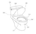
도 8과 도 9는 종래의 좌변기를 도시한 것으로서, 도면 부호 200은 좌변기를 도시한 것이다.8 and 9 show a conventional left side lid, and
상기 좌변기(200)는 도 8과 같이 사용자가 앉을 수 있는 좌변기(210)와, 상기 좌변기(210)의 상부 후면에 설치 구성되며, 세척수를 저장할 수 있는 저수조(220)로 구성된다.The
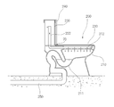
상기 좌변기(200)를 구성하고 있는 좌변기본체(210)의 상부 내측에는 저수조(220)에 들어 있는 세척수가 상기 좌변기본체(210) 내부로 유출되도록 배출홀(212)이 등간격으로 형성되고, 상기 좌변기본체(210)의 바닥면에는 오수관(250)과 연결되는 용변기 배출통로(211)가 형성되어, 상기 용변기 배출통로(211)를 통해 좌변기본체(210)에 있는 세척수와 변이 오수관(250)을 통해 정화조로 유입된다.A
상기 좌변기본체(210)의 상부면에 설치되는 저수조(220)의 바닥면에는 좌변기본체(210)에 구비된 배출홀(212)과 연통 되는 출구(221)가 형성되어, 저수조(220)의 내부에 들어 있는 세척수가 배출홀(212)을 통해 좌변기본체(210)로 유출되도록 한다. An
이때, 출구(221)에는 저수조(220)에 구비된 개폐손잡이(223)의 작동에 따라서 출구(221)를 개폐하는 개폐부(도면에 미 도시)가 설치됨을 밝히는 바이다.At this time, the
따라서, 개폐손잡이(223)를 사용자가 작동시키게 되면, 출구(221)를 차단한 개폐부가 상부로 회전되면서 상기 출구(221)를 개방하고, 그 개방된 출구(221)를 통해 저수조(220) 내부에 들어 있는 세척수가 배출홀(212)을 통해 좌변기본체(210) 내부로 유입되기 때문에 상기 좌변기본체(210)에 있는 변은 세척수와 함께 용변기 배출통로(211)를 통해 오수관(250)으로 배출되는 것이다.When the user turns on the opening /
이와 같이 세척수를 저장하고 좌변기본체(210)로 유출시키는 출구(221)가 구비된 저수조(220)의 내부에는 넘침방지관(222)이 배출홀(212)과 연결 되게 수직으로 설치 구성된다.The
상기 넘침방지관(222)이 저수조(220)의 내부에 설치 구성되므로, 상기 넘침방지관(222)으로 인해 저수조(220)의 내부로 유입된 세척수가 상기 저수조(220)의 상단을 통해 넘치는 것을 방지할 수 있는 것이다.The
한편, 좌변기본체(210)의 상부에는 좌변기커버(230)와 뚜껑(240)이 힌지로 결합 되므로, 좌변기커버(230)로 인해 용변을 보는 도중에 변이 피부에 묻는 것을 최대한으로 방지할 수 있을 뿐만 아니라 힌지(240)를 중심으로 뚜껑(240)을 항상 좌변기본체(210)의 상부면에 결합시켜 좌변기(200)의 청결 상태를 유지한다.Since the left-
그러나 종래의 수세식 좌변기의 문제점은 사용자가 좌변기본체(210)의 좌변기커버(230)에 앉아서 용변을 보는 도중에 변으로 발생 되는 악취가 사용자에게 그대로 전달되거나 변의 냄새가 그대로 화장실 내부에 남아 있기 때문에 좌변기(200)에 앉아서 용변을 보기가 용이하지 못하는 문제점이 발생하게 되었다.However, the problem of the conventional flush toilet seat is that the user is sitting on the left-
특히, 좌변기본체(210)에 앉아서 변을 보게 되면, 그 변에서 발생 되는 악취가 화장실 내부에 존재하기 때문에 화장실에 남아 있는 변의 악취로 인해 다른 사람이 화장실을 사용하기가 용이하지 못하는 문제점이 발생하게 되었다.Particularly, when sitting on the
이러한 문제점을 해결하기 위해서 좌변기본체(210)에 앉아서 용변을 보는 도중에 발생 되는 악취를 제거하거나 또는 화장실 내부에 있는 악취를 제거할 수 있도록 환풍기를 화장실에 설치하는 경우도 있었다.In order to solve such a problem, there has been a case where the ventilator is installed in the toilet so as to remove the odor generated during the toilet seat sitting on the
그러나 화장실 내부에 환풍기를 설치하였다 하더라도 좌변기본체(210)에 앉아서 변을 보는 도중에, 그 변에서 발생 되는 악취가 사용자에게 그대로 전달될 뿐만 아니라 화장실을 사용한 후에는 바로 환풍기를 Off 시키기 때문에 화장실 내부에는 변의 악취가 지속적으로 남아 있어 다음 사용자가 화장실을 사용하기가 용이하지 못하는 문제점이 발생하는 경우도 있었다.
However, even if the ventilator is installed inside the toilet, the odor generated at the side of the
따라서, 상기 문제점을 해결하기 위한 본 고안은 저수조에 구비된 넘침방지관과 오수관을 악취배출수단이 구비된 배출관으로 연결하여, 용변을 보는 도중에 발생 되는 악취가 악취배출수단으로 인해 오수관으로 배출되도록 하므로, 용변을 보는 도중에 발생 되는 악취를 없앨 수 있을 뿐만 아니라 상기 악취배출수단에 의해 배출관에 구비된 저수파이프의 내부로 유체가 유출하거나 차단하기 때문에 오수관으로 통해 외부의 악취가 좌변기로 유입되는 것을 방지할 수 있으며, 또한 악취배출수단은 외부로 노출되게 좌변기와 오수관을 연결하는 배출관에 설치 구성하므로, 상기 악취배출수단의 설치를 용이하게 할 수 있으며, 이로 인하여 악취배출수단의 설치 비용 및 설치 시간을 줄일 수 있으며, 상기 좌변기본체에는 작동센서를 설치하고, 상기 작동센서의 On/Off 신호에 의해 회전되는 송풍팬을 상기 배출관에 설치 구성하여 상기 송풍팬으로 인해 변의 악취가 오수관으로 빠르게 배출시킬 수 있으며, 상기 작동센서는 좌변기본체의 상부에 상,하로 회동 되는 좌변기커버에 앉은 사용자의 하중에 의해 On/Off 작동되기 때문에 원하는 시간만 선택적으로 작동되도록 한 악취 제거 기능을 갖는 수세식 좌변기를 제공함을 목적으로 한다.
In order to solve the above problems, the present invention connects the overflow prevention pipe and the sewage pipe provided in the water storage tank to a discharge pipe provided with the odor discharge means, so that the odor generated during the discharge of the odor is discharged to the discharge pipe Not only the odor generated during the use of the toilet can be eliminated, but also the odor is discharged or blocked into the water storage pipe provided in the discharge pipe by the odor discharge means, In addition, since the malodor discharge means is installed in a discharge pipe connecting the left side and the drain pipe to the outside, it is possible to facilitate the installation of the malodor discharge means, thereby reducing the installation cost and installation time of the malodor discharge means An operation sensor is installed in the body of the toilet body, A blowing fan rotated by an on / off signal of the blowing fan is installed in the discharge pipe, so that the odor of the side can be quickly discharged to the sewage pipe due to the blowing fan. The operation sensor includes a left- The present invention provides a flush toilet seat having a malodor removing function for selectively operating only a desired time since it is turned on / off by the load of a user sitting on the cover.
따라서, 상기 문제점을 해결하기 위한 본 고안은,Therefore, in order to solve the above problems,
세척수를 저장하도록 형성되며, 내부에는 넘침방지관이 구비된 저주조와, 넘침방지관과 연결되는 다수의 배출홀이 내부에 형성된 좌변기본체로 구성되는 좌변기를 포함하는 악취 제거 기능을 갖는 수세식 좌변기에 있어서, A flush toilet with a malodor removing function, which comprises a toilet bowl formed to store washing water, a toilet bowl having an overflow prevention pipe therein, and a toilet seat having a plurality of discharge holes connected to the overflow prevention pipe, ,
입구는 넘침방지관의 상단에 연결되며, 출구는 오수관과 연결되며, 중간에는 수평으로 절곡 형성되어 유체를 저장하는 저수공간이 내부에 형성된 저수파이프가 구비된 배출관과; A discharge pipe having an inlet connected to an upper end of the overflow prevention pipe, an outlet connected to the drain pipe, a drain pipe formed by bending horizontally in the middle and having a water storage space for storing the fluid therein;
좌변기본체에서 발생 되는 악취를 상기 좌변기본체와 연결된 오수관을 통해 외부로 배출시킬 수 있도록 상기 저수파이프의 내부로 유체를 공급 또는 차단하는 악취배출수단;으로 구성된 것을 특징으로 한다.
And a malodor discharge means for supplying or blocking the fluid to the inside of the water storage pipe so as to discharge the odor generated in the body of the toilet body to the outside through a sewage pipe connected to the toilet body.
본원 고안에 의하면, 저수조에 구비된 넘침방지관과 오수관을 악취배출수단이 구비된 배출관으로 연결하여, 용변을 보는 도중에 발생 되는 악취가 악취배출수단으로 인해 오수관으로 배출되도록 하므로, 용변을 보는 도중에 발생 되는 악취를 최대한으로 줄일 수 있을 뿐만 아니라 상기 악취배출수단에 의해 배출관에 구비된 저수파이프의 내부로 유체가 유출하거나 차단하기 때문에 오수관으로 통해 외부의 악취가 좌변기로 유입되는 것을 방지할 수 있는 효과를 기대할 수 있는 것이다.According to the present invention, the overflow prevention pipe and the sewage pipe provided in the water tank are connected to the discharge pipe provided with the odor discharge means, so that the odor generated during the discharge of the odor is discharged to the discharge pipe due to the odor discharge means, It is possible to prevent the odor from outside flowing into the toilet seat through the sewage pipe because the odor discharge means can discharge or block the fluid into the inside of the water storage pipe provided in the discharge pipe It can be expected.
또한, 악취배출수단은 외부로 노출되게 좌변기와 오수관을 연결하는 배출관에 설치 구성하므로, 상기 악취배출수단의 설치를 용이하게 할 수 있으며, 이로 인하여 악취배출수단의 설치 비용 및 설치 시간을 줄일 수 있다.In addition, since the malodor discharge means is installed in a discharge pipe connecting the toilet seat and the sewage pipe to be exposed to the outside, it is possible to facilitate the installation of the malodor discharge means, thereby reducing the installation cost and installation time of the malodor discharge means .
그리고 좌변기본체에는 작동센서를 설치하고, 상기 작동센서의 On/Off 신호에 의해 회전되는 송풍팬을 상기 배출관에 설치 구성하여 상기 송풍팬으로 인해 변의 악취가 오수관으로 빠르게 배출시킬 수 있으며, 상기 작동센서는 좌변기본체의 상부에 상,하로 회동 되는 좌변기커버로에 앉은 사용자의 하중에 의해 On/Off 작동되기 때문에 필요한 시간 동안만 작동되도록 할 수 있고, 환풍 작동되도록 할 수 있으며, 이로인해 소비전력 낭비를 줄여줄 수 있도록 하는 효과를 기대할 수 있는 것이다.
In addition, an operation sensor may be installed in the body of the toilet seat, and a blowing fan rotated by an on / off signal of the operation sensor may be installed in the discharge pipe, so that the odor of the side can be quickly discharged to the sewage pipe due to the blowing fan. Is operated by the load of the user sitting on the left side cover which is rotated up and down on the upper part of the body of the body of the toilet so that it can be operated only for the necessary time and can be operated for ventilation, It is possible to expect the effect of reducing the number of times.
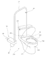
도 1은 본 고안의 악취 제거 기능을 갖는 수세식 좌변기를 도시한 사시도.
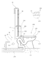
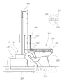
도 2는 본 고안의 악취 제거 기능을 갖는 수세식 좌변기를 도시한 단면도.
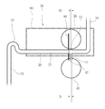
도 3은 본 고안의 수세식 좌변기에 설치되는 악취배출수단의 제1 실시 예를 도시한 부분 확대 단면도.
도 4와 도 5는 본 고안의 악취배출수단의 제1 실시 예의 작동 상태를 도시한 부분 확대 단면도.
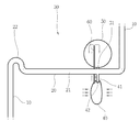
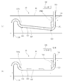
도 6은 본 고안의 악취 제거 기능을 갖는 수세식 좌변기에 설치되는 악취배출수단의 제2 실시 예를 도시한 단면도.
도 7은 본 고안의 악취배출수단의 제2 실시 예의 작동 상태를 도시한 단면도.
도 8은 종래의 수세식 좌변기를 도시한 사시도.
도 9는 종래의 수세식 좌변기를 도시한 단면도.1 is a perspective view showing a flush toilet seat having a malodor removing function according to the present invention.
2 is a sectional view showing a flush toilet seat having a malodor removing function according to the present invention.
3 is a partially enlarged cross-sectional view showing a first embodiment of a malodor discharge means provided in a flush toilet seat of the present invention;
4 and 5 are partially enlarged sectional views showing the operating state of the first embodiment of the malodor discharge means of the present invention.
FIG. 6 is a sectional view showing a second embodiment of a malodor discharge means provided in a flush toilet seat having a malodor removing function according to the present invention; FIG.
7 is a sectional view showing an operating state of the second embodiment of the malodor discharge means of the present invention;
8 is a perspective view showing a conventional flush toilet seat.
9 is a sectional view showing a conventional flush toilet seat.
이하, 첨부된 도 1 내지 도 7을 이용하여 본 고안의 바람직한 실시 예를 설명하면 다음과 같다.Hereinafter, preferred embodiments of the present invention will be described with reference to FIGS. 1 to 7 attached hereto.
먼저, 본 고안은 종래 기술과 동일한 구성 요소에 관하여 동일한 도면 부호를 표기하여 중복되는 도면 부호의 설명은 생략하기로 한다.First, in the present invention, the same reference numerals are denoted for the same constituent elements as those of the prior art, and the description of the same reference numerals will be omitted.
상기 도면에 의하면 본 고안은, According to the drawings,
세척수를 저장하도록 형성되며, 내부에는 넘침방지관(222)이 구비된 저주조(220)와, 넘침방지관(222)과 연결되는 다수의 배출홀(212)이 내부에 형성된 좌변기본체(210)로 구성되는 좌변기(200)를 포함하는 악취 제거 기능을 갖는 수세식 좌변기에 있어서, A
입구는 넘침방지관(222)의 상단에 연결되며, 출구는 오수관(250)과 연결되며, 중간에는 수평으로 절곡 형성되어 유체를 저장하는 저수공간(21)이 내부에 형성된 저수파이프(20)가 구비된 배출관(10)과; The inlet is connected to the upper end of the
좌변기본체(210)에서 발생 되는 악취를 상기 좌변기본체(210)와 연결된 오수관(250)을 통해 외부로 배출시킬 수 있도록 상기 저수파이프(20)의 내부로 유체를 공급 또는 차단하는 악취배출수단(30);으로 구성된 것을 특징으로 한다.A malodor discharge means 30 for supplying or blocking a fluid to the inside of the
상기 넘침방지관(222)과 연결되는 배출관(10)의 일단인 입구측에는 다수의 유입홀(11)을 도 2와 같이 형성하여 저수조(220) 내부로 세척수가 과하게 유입 시 유입홀(11)을 통해 넘침방지관(222)으로 유입되면서 세척수가 외부로 유출되도록 한다.A plurality of
상기 배출관(10)에 구비된 저수파이프(20)에 형성되는 악취배출수단(30)은 도 1과 같이 하우징(90)의 내부에 설치된다.The malodor discharge means 30 formed in the
상기 악취배출수단(30)이 설치되는 배출관(10)에는 좌변기본체(210)의 상부면에 설치된 작동센서(70)의 On/Off 신호에 의해 회전되는 송풍팬(80)을 설치 구성하여, 상기 송풍팬(80)이 좌변기본체(210)에 있는 변의 냄새 입자를 강하게 오수관으로 유출시켜 악취를 외부로 유출시킬 수 있음과 동시에 악취가 역류되는 것을 방지한다.The
상기 배출관에 설치되는 악취배출수단(30)은 설치된 구성 요소에 따라서 도 3 내지 도 5와 같이 제1 실시 예와 도 6과 도 7과 같이 제2 실시 예로 분리 구성하여 설명하기로 한다.
The malodor discharge means 30 installed in the discharge pipe will be described separately as the first embodiment and the second embodiment as shown in Figs. 3 and 5, according to the installed components, as shown in Figs. 6 and 7.
◆ 제1 실시 예 ◆<First Embodiment>
상기 악취배출수단(30)은, 저수파이프(20)의 하부 중간에는 물을 저장하는 신축성 재질의 제1 챔버(40)를 제1 환수관(41)으로 결합하고,The malodor discharge means 30 includes a
저수파이프(20)의 상부 중간에는 신축성 재질의 제2 챔버(50)를 제2 환수관(51)으로 결합하며,A
제1 챔버(40)에 가해지는 압력에 의해 상기 제1 챔버(40)에 들어 있는 물을 제2 챔버(50)로 유입시킬 수 있도록 제1 챔버(40)와 제2 챔버(50)를 연결관(60)으로 연결하되,The
제1 환수관(41)의 직경(D1)은 제2 환수관(51)의 직경(D2) 보다 크게 형성하여 저수공간(21)에 유치게 채워지는 시간을 지연시킬 수 있도록 구성한 것을 특징으로 한다.The diameter D1 of the first
그리고 제1 챔버(40)에 가해지는 압력에 의해 제1 환수관(41)의 끝단을 개폐하는 밸브(42)를 상기 제1 환수관(41)의 끝단에 더 설치 구성하여, 상기 제1 챔버(40)에 가해지는 압력에 의해 상기 제1 챔버(40) 내부에 들어 있는 물이 제2 환수관(51)을 통해 제2 챔버(50) 내부로 역류 되는 것을 방지할 수 있도록 구성한 것을 특징으로 한다.
A
이와 같이 결합 구성된 본 고안의 바람직한 작동 상태 및 효과를 설명하면 다음과 같다.A preferable operation state and effect of the present invention will be described as follows.
먼저, 용변을 볼 사용자는 좌변기(200)를 구성하고 있는 좌변기본체(210)에 구비된 좌변기커버(230)에 앉으면 체중으로 좌변기본체(210)의 상부면에 설치된 작동센서(70)가 On 된다.First, when the user seated on the left-
작동센서(70)의 작동 신호에 의해 배출관(10)의 내부에 설치된 송풍팬(80)이 작동됨과 동시에 좌변기본체(210)에 구비된 좌변기커버(230)에 앉은 사용자는 도 4와 같이 악취배출수단(30)에 구비된 제1 챔버(40)를 손으로 눌러, 상기 제1 챔버(40) 내부에 들어 있는 물이 연결관(60)을 통해 제2 챔버(50) 내부로 유입되도록 하는 데, 이때 제1 환수관(41)의 끝단에 설치된 밸브(42)가 도 4와 같이 상부로 회전되면서 제1 환수관(41)의 끝단을 차단한다. A user who is seated on the left-
상기 밸브(42)가 제1 환수관(41)의 끝단을 차단하기 때문에 제1 챔버(40)의 내부에 들어 있는 유체가 제2 챔버(50)로 유입 시 제1 환수관(41)을 통해 저수파이프(20)의 저수공간(21)으로 유입되는 것을 방지할 수 있으며, 이로 인하여 저수파이프(20)의 일단에 구비된 절곡단(22)을 통해 유체가 오수관(250)으로 유입되는 것을 방지한다.Since the
이와 같은 상태에서 제1 챔버(40)를 가압했던 손을 놓게 되면, 제1 환수관(41)을 차단한 밸브(42)는 저수파이프(20)의 저수공간(21)에 들어 있는 물의 하중에 의해 도 5와 같이 아래로 회전되면서 제1 환수관(41)을 개방시키고, 그 개방된 제1 환수관(41)을 통해 상기 저수파이프(20)의 내부에 있는 물이 제1 챔버(40)로 유입된다.The
저수파이프(20)에 구비된 물이 제1 챔버(40) 내부로 유입되기 때문에 상기 저수파이프(20)의 저수공간(21)은 개방된 상태를 유지하는 것이며, 이로 인하여 배출관(10) 내부로 유입된 변의 악취는 저수파이프(20)의 내부를 통과하면서 오수관(250)으로 유입되는 것이다.The water stored in the
따라서, 좌변기본체(200)에 앉아서 용변을 보는 사용자는 악취배출수단(30)을 구성하고 있는 저수파이프(20)의 내부를 통해 오수관(250)으로 유입되므로, 상기 좌변기(200)에 구비된 변에서 발생 되는 악취를 외부인 오수관(250)으로 신속하게 배출시킬 수 있는 것이다.Therefore, the user sitting on the
특히, 송풍팬(80)이 배출관(10) 내부에서 지속적으로 오수관(250) 쪽으로 강한 바람을 제공하기 때문에 오수관(250)에서 발생 되는 악취가 역류하는 것을 방지할 수 있다.Particularly, since the blowing
한편, 좌변기(200)에 앉아서 변을 보는 동안에 제2 챔버(50)로 유입된 물은 도 5와 같이 제2 연결관(51)을 통해 이와 같이 저수파이프(20)로 유출되고, 그 저수파이프(20)로 유출된 물은 제1 환수관(41)을 통해 제1 챔버(40)의 내부공간을 다 채운 후에 저수파이프(20)의 저수공간(21)을 채우게 된다.5, the water flowing into the
이때, 제1 환수관(41)의 직경(D1)은 제2 환수관(51)의 직경(D1)보다 크게 형성하므로, 제2 환수관(51)을 통해 저수공간(21) 내부로 소량의 물이 유출되며, 이로 인하여 제1 챔버(40)와 저수파이프(20)의 저수공간(21)는 천천히 채워지게 되는 것이다.The diameter D1 of the first
이와 같이 서로 다른 직경으로 제1 환수관(41)과 제2 환수관(51)을 형성하므로, 사용자는 좌변기(200)에 앉아서 용변을 보는 시간인 5분 내지 10 분 동안 변에서 발생 되는 악취를 외부인 오수관(250)으로 배출시킬 수 있는 것이다.Since the first and second
따라서, 용변을 보는 도중에 변으로 발생 되는 악취를 사용자가 맡는 경우가 없게 된다.Therefore, there is no case where the user takes on the odor generated in the stomach while viewing the toilet.
그리고 제1 챔버(40)와 저수파이프(20)의 저수공간(21)으로 유체가 채워지게 되면, 오수관(250)을 통해 역류 되는 악취를 유체가 차단시켜 악취가 화장실로 유입되는 것을 막아준다.When the fluid is filled in the
또한, 저수조에 구비된 넘침방지관(222)과 오수관(250)을 연결하는 배출관(10)은 좌변기(200)의 외부로 노출되게 설치한 상태에서 그 배출관(10)에 악취배출수단(30)을 설치하므로, 상기 악취배출수단(30)의 설치 비용 및 시간을 현저히 줄일 수 있으며, 이로 인하여 악취배출수단(30)에 구비된 좌변기(200)의 생산력을 향상시킬 수 있다.
The
◆ 제2 실시 예 ◆Example 2
제2 실시 예의 설명에 앞서 제1 실시 예와 동일한 구성 요소에 관하여 동일한 도면 부호를 표기하여 중복되는 도면 부호의 설명은 생략하기로 한다.Prior to the description of the second embodiment, the same reference numerals are denoted for the same constituent elements as those of the first embodiment, and the description of the same reference numerals will be omitted.
상기 도면에 의하면 제2 실시 예의 악취배출수단(30)은, According to the figure, the malodor discharge means (30) of the second embodiment,
넘침방지관(222)의 상단에 결합 되는 입구가 구비된 제1 배출관(100)을 형성하고,A
오수관(250)과 연결되는 출구가 구비된 제2 배출관(110)을 형성하며,A
유체를 저장하는 저수공간(121)이 구비된 저수파이프(120)를 상기 제1 배출관(100)과 제2 배출관(110)로 연결하되 ,A
상기 저수파이프(120)의 양측단에는 자바라관(130)(130a)을 형성하고,The
자바라관(130)(130a)이 결합 된 저수파이프(120)의 일단을 상,하로 이동시켜 상기 저수파이프(120) 내부에 들어 있는 유체가 저수공간(121)을 개폐하도록 구동센서(140)를 상기 좌변기본체(210)의 상부면에 설치 구성하여, The
상기 좌변기본체(210)에 구비된 구동센서(140)의 구동신호에 따라 자바라관(130)(130a)이 구비된 저수파이프(120)의 일단에 상,하로 이동되면서 상기 좌변기본체(210)에 있는 변으로부터 발생 되는 악취를 오수관(250)을 통해 외부로 배출되도록 구성한 것을 특징으로 한다.The
본 고안의 제2 실시 예는 넘침방지관(222)과 연결되는 제1 배출관(100)과 오수관(250)과 연결되는 제2 배출관(110) 사이로 자바라관(130)(130a)이 양측단에 구비된 저수파이프(120)를 결합하고, 그 저수파이프(120)의 일단을 상,하로 이동시키는 구동센서(140)를 좌변기본체(210)의 상부면에 설치 구성하여 사용자가 좌변기본체(210)에 앉아서 변을 보는 도중에 발생 되는 악취를 제1 배출관(100)과 제2 배출관(110)을 통해 오수관(250)으로 배출시킬 수 있도록 한 것이다. The second embodiment of the present invention is characterized in that the
이때, 제1 배출관(100)과 연결되는 자바라관(130)에는 구동센서(140)의 제어 신호에 의해 On/Off 작동되는 작동바(151)가 구비된 솔레노이드밸브(150)를 하우징(90)의 내부에 설치 구성한다.A
따라서, 구동센서(140)가 작동됨과 동시에 솔레노이드밸브(150)의 작동바(151)가 제1 배출관(100)에 결합 된 자바라관(150)을 도 7의 (b)와 같이 수축시켜 저수파이프(120)의 일단을 상부로 이동시키기 때문에 저수공간(121)을 차단하는 유체는 상기 저수공간(121)을 개방시키는 것이며, 이로 인하여 변의 악취는 저수파이프(120)와 제2 배출관(110)을 통해 외부로 배출되는 것이다.7 (b), the operating
그리고 5분 내지 10분 정도 시간이 경과하게 되면, 저수파이프(120) 일단을 상부로 이동시킨 솔레노이드밸브(150)의 작동바(151)가 도면상 아래로 이동되면서 상기 저수파이프(120)의 일단에 구비된 자바라관(130)을 수축시키기 때문에 유체는 다시 저수공간(121)을 차단하는 것이며, 이로 인하여 악취가 제2 배출관(110)을 통해 역류 되는 것을 방지할 수 있는 것이다.The
이때, 하우징(90)의 내부에는 자바라관(130)(130a)에 의해 수축, 이완되는 저수파이프(120)의 양측단을 지지하는 받침판(122)을 형성하는 것이 바람직하다.
At this time, it is preferable to form a
◆ 제 3 실시예 ◆Example 3
제 3 실시예는 제 1 실시예와 제 2 실시예의 구성을 그대로 사용하면서 펌프를 이용하여 강하게 공기를 펌핑하여 저수공간에 채워진 물의 수위가 낮아지도록 하여 저수공간에 생성된 공기통로를 통해 악취가 배출되도록 한 것이다.
In the third embodiment, the structure of the first and second embodiments is used as it is, and the air is strongly pumped by using the pump to lower the water level of the water filled in the water storage space, and the odor is discharged through the air passage created in the water storage space .
10: 배출관, 11: 유입홀,
20: 저수파이프, 21: 저수공간,
22: 절곡단, 23: 연결관,
30: 악취배출수단, 40: 제1 챔버,
41: 제1 환수관, 42: 밸브,
50: 제2 챔버, 51: 제2 환수관,
60: 연결관, 70: 작동센서,
80: 송풍팬, 90: 하우징,
100: 제1 배출관, 110: 제2 배출관,
120: 저수파이프, 121: 저수공간,
122: 받침판, 130,130a: 자바라관,
140: 구동센서, 150: 솔레노이드밸브,
151: 작동바, 10: discharge pipe, 11: inflow hole,
20: water storage pipe, 21: water storage space,
22: bending section, 23: connecting pipe,
30: odor discharge means, 40: first chamber,
41: first water return pipe, 42: valve,
50: second chamber, 51: second return pipe,
60: connector, 70: operation sensor,
80: blowing fan, 90: housing,
100: first discharge pipe, 110: second discharge pipe,
120: water storage pipe, 121: water storage space,
122: base plate, 130,130a: bellows tube,
140: drive sensor, 150: solenoid valve,
151: Operation bar,
Claims (5)
입구는 넘침방지관(222)의 상단에 연결되며, 출구는 오수관(250)과 연결되며, 중간에는 수평으로 절곡 형성되어 유체를 저장하는 저수공간(21)이 내부에 형성된 저수파이프(20)가 구비된 배출관(10)과;
좌변기본체(210)에서 발생 되는 악취를 상기 좌변기본체(210)와 연결된 오수관(250)을 통해 외부로 배출시킬 수 있도록 상기 저수파이프(20)의 내부로 유체를 공급 또는 차단하는 악취배출수단(30);으로 구성된 것을 특징으로 하는 악취 제거 기능을 갖는 수세식 좌변기.
A toilet bowl 220 having an overflow prevention pipe 222 and a plurality of discharge holes 212 connected to the overflow prevention pipe 222 for storing washing water, (200) having a malodor removing function, the flush toilet seat
The inlet is connected to the upper end of the overflow prevention pipe 222, the outlet is connected to the drain pipe 250, and the water storage pipe 20 formed in the middle thereof is formed by horizontally bending and having a water storage space 21 for storing the fluid therein A discharge tube 10 provided therein;
A malodor discharge means 30 for supplying or blocking a fluid to the inside of the water storage pipe 20 so that odor generated in the toilet seat main body 210 can be discharged to the outside through a water discharge pipe 250 connected to the toilet seat main body 210 And a control unit for controlling the flushing operation of the flush toilet.
저수파이프(20)의 하부 중간에는 물을 저장하는 신축성 재질의 제1 챔버(40)를 제1 환수관(41)으로 결합하고,
저수파이프(20)의 상부 중간에는 신축성 재질의 제2 챔버(50)를 제2 환수관(51)으로 결합하며,
제1 챔버(40)에 가해지는 압력에 의해 상기 제1 챔버(40)에 들어 있는 물을 제2 챔버(50)로 유입시킬 수 있도록 제1 챔버(40)와 제2 챔버(50)를 연결관(60)으로 연결하되,
제1 환수관(41)의 직경(D1)은 제2 환수관(51)의 직경(D2) 보다 크게 형성하여 저수공간(21)에 유치게 채워지는 시간을 지연시킬 수 있도록 구성한 것을 특징으로 하는 악취 제거 기능을 갖는 수세식 좌변기.
The malodor discharging means (30) according to claim 1,
A first chamber (40) made of a stretchable material, which stores water, is connected to the lower part of the water storage pipe (20) by a first water return pipe (41)
A second chamber 50 of a stretchable material is connected to the upper middle of the water storage pipe 20 by a second water return pipe 51,
The first chamber 40 and the second chamber 50 are connected to each other so that the water contained in the first chamber 40 can be introduced into the second chamber 50 by the pressure applied to the first chamber 40 To the tube (60)
The diameter D1 of the first water return pipe 41 is formed to be larger than the diameter D2 of the second water return pipe 51 so as to delay the filling time of the water storage space 21 Flush toilet with odor removal function.
제1 챔버(40)에 가해지는 압력에 의해 제1 환수관(41)의 끝단을 개폐하는 밸브(42)를 상기 제1 환수관(41)의 끝단에 더 설치 구성하여, 상기 제1 챔버(40)에 가해지는 압력에 의해 상기 제1 챔버(40) 내부에 들어 있는 물이 제2 환수관(51)을 통해 제2 챔버(50) 내부로 역류 되는 것을 방지할 수 있도록 구성한 것을 특징으로 하는 악취 제거 기능을 갖는 수세식 좌변기.
The method according to claim 2,
The valve 42 for opening and closing the end of the first water return pipe 41 is further provided at the end of the first water return pipe 41 by the pressure applied to the first chamber 40, The water contained in the first chamber 40 can be prevented from flowing back into the second chamber 50 through the second water return pipe 51 due to the pressure applied to the first chamber 40. [ Flush toilet with odor removal function.
좌변기본체(210)의 상부에는 작동센서(70)를 설치하고,
작동센서(70)의 제어 신호에 의해 On/Off 작동되는 송풍팬(80)을 상기 배출관(10)에 설치 구성한 것을 특징으로 하는 악취 제거 기능을 갖는 수세식 좌변기.
The method according to claim 1,
An operation sensor 70 is installed on the upper portion of the toilet body 210,
And a blowing fan (80) which is turned on / off by a control signal of the operation sensor (70) is installed in the discharge pipe (10).
넘침방지관(222)의 상단에 결합 되는 입구가 구비된 제1 배출관(100)을 형성하고,
오수관(250)과 연결되는 출구가 구비된 제2 배출관(110)을 형성하며,
유체를 저장하는 저수공간(121)이 구비된 저수파이프(120)를 상기 제1 배출관(100)과 제2 배출관(110)로 연결하되 ,
상기 저수파이프(120)의 양측단에는 자바라관(130)(130a)을 형성하고,
자바라관(130)(130a)이 결합 된 저수파이프(120)의 일단을 상,하로 이동시켜 상기 저수파이프(120) 내부에 들어 있는 유체가 저수공간(121)을 개폐하도록 구동센서(140)를 상기 좌변기본체(210)의 상부면에 설치 구성하여,
상기 좌변기본체(210)에 구비된 구동센서(140)의 구동신호에 따라 자바라관(130)(130a)이 구비된 저수파이프(120)의 일단에 상,하로 이동되면서 상기 좌변기본체(210)에 있는 변으로부터 발생 되는 악취를 오수관(250)을 통해 외부로 배출되도록 구성한 것을 특징으로 하는 악취 제거 기능을 갖는 수세식 좌변기.
The malodor discharging means (30) according to claim 1,
A first exhaust pipe 100 having an inlet coupled to an upper end of the overflow prevention pipe 222 is formed,
A second discharge pipe 110 having an outlet connected to the sewage pipe 250 is formed,
A water discharge pipe 120 having a water storage space 121 for storing a fluid is connected to the first discharge pipe 100 and the second discharge pipe 110,
The bellows pipes 130 and 130a are formed at both ends of the water storage pipe 120,
The bellows pipe 130 is moved up and down one end of the water storage pipe 120 to connect the drive sensor 140 to the water storage pipe 120 so that the fluid contained in the water storage pipe 120 opens and closes the water storage space 121 And is installed on the upper surface of the toilet seat main body 210,
The valve body 120 is moved upward and downward to one end of the water storage pipe 120 provided with the bellows pipes 130 and 130a according to the driving signal of the driving sensor 140 provided in the toilet body 210, And the odor generated from the side where the odor is generated is discharged to the outside through the sewer pipe (250).
Priority Applications (1)
| Application Number | Priority Date | Filing Date | Title |
|---|---|---|---|
| KR2020150003659U KR200482587Y1 (en) | 2015-06-08 | 2015-06-08 | A Toilet Bowl |
Applications Claiming Priority (1)
| Application Number | Priority Date | Filing Date | Title |
|---|---|---|---|
| KR2020150003659U KR200482587Y1 (en) | 2015-06-08 | 2015-06-08 | A Toilet Bowl |
Publications (2)
| Publication Number | Publication Date |
|---|---|
| KR20160004319U true KR20160004319U (en) | 2016-12-19 |
| KR200482587Y1 KR200482587Y1 (en) | 2017-02-14 |
Family
ID=57708948
Family Applications (1)
| Application Number | Title | Priority Date | Filing Date |
|---|---|---|---|
| KR2020150003659U Expired - Fee Related KR200482587Y1 (en) | 2015-06-08 | 2015-06-08 | A Toilet Bowl |
Country Status (1)
| Country | Link |
|---|---|
| KR (1) | KR200482587Y1 (en) |
Families Citing this family (1)
| Publication number | Priority date | Publication date | Assignee | Title |
|---|---|---|---|---|
| KR102370999B1 (en) | 2021-04-16 | 2022-03-10 | 배윤주 | Toilet with automatic detergent supply |
Citations (2)
| Publication number | Priority date | Publication date | Assignee | Title |
|---|---|---|---|---|
| KR100852847B1 (en) * | 2007-02-22 | 2008-08-18 | 김영배 | Odor removal device for toilet |
| KR200468748Y1 (en) * | 2013-02-22 | 2013-09-04 | 권우득 | Connecting device for a toilet bowl |
-
2015
- 2015-06-08 KR KR2020150003659U patent/KR200482587Y1/en not_active Expired - Fee Related
Patent Citations (2)
| Publication number | Priority date | Publication date | Assignee | Title |
|---|---|---|---|---|
| KR100852847B1 (en) * | 2007-02-22 | 2008-08-18 | 김영배 | Odor removal device for toilet |
| KR200468748Y1 (en) * | 2013-02-22 | 2013-09-04 | 권우득 | Connecting device for a toilet bowl |
Also Published As
| Publication number | Publication date |
|---|---|
| KR200482587Y1 (en) | 2017-02-14 |
Similar Documents
| Publication | Publication Date | Title |
|---|---|---|
| JP6691659B2 (en) | Flush toilet | |
| KR20100097089A (en) | Pressurized trap water saver toilet | |
| JP5361250B2 (en) | Western style flush toilet | |
| JP2017504739A (en) | Flush toilet seat with a bad smell removal function | |
| JP5299832B2 (en) | Flush toilet | |
| JP4305359B2 (en) | Toilet device | |
| KR101908846B1 (en) | cleaning liquid supply device and toilet bowl cistern including the same | |
| KR200482587Y1 (en) | A Toilet Bowl | |
| JP5412779B2 (en) | Western-style toilet | |
| JP2008240402A (en) | Western-style water closet | |
| EP3553236A1 (en) | Water seal device for removing odour of toilet | |
| JP2008240401A (en) | Western-style water closet | |
| JP5094873B2 (en) | Water-saving Western-style toilet | |
| KR100798661B1 (en) | Water-saving toilet | |
| KR102251978B1 (en) | Apparatus for Removing Odor from Toilet Bowl | |
| JP2007046307A (en) | Toilet bowl flushing apparatus | |
| KR101478111B1 (en) | Electronic toilet stool | |
| KR20190089256A (en) | Toilet bowl with smell removal device | |
| JP4857845B2 (en) | Toilet equipment and toilet cleaning method | |
| JP4941892B2 (en) | Flush toilet | |
| JPH09296495A (en) | Vacuum flush toilet bowl | |
| JP3925214B2 (en) | Toilet device | |
| JP4281519B2 (en) | Toilet bowl cleaning device | |
| JP4052085B2 (en) | Toilet bowl cleaning device | |
| JP2020037863A (en) | Urinal device |
Legal Events
| Date | Code | Title | Description |
|---|---|---|---|
| A201 | Request for examination | ||
| UA0108 | Application for utility model registration |
St.27 status event code: A-0-1-A10-A12-nap-UA0108 |
|
| UA0201 | Request for examination |
St.27 status event code: A-1-2-D10-D11-exm-UA0201 |
|
| E902 | Notification of reason for refusal | ||
| UE0902 | Notice of grounds for rejection |
St.27 status event code: A-1-2-D10-D21-exm-UE0902 |
|
| E13-X000 | Pre-grant limitation requested |
St.27 status event code: A-2-3-E10-E13-lim-X000 |
|
| P11-X000 | Amendment of application requested |
St.27 status event code: A-2-2-P10-P11-nap-X000 |
|
| P13-X000 | Application amended |
St.27 status event code: A-2-2-P10-P13-nap-X000 |
|
| UG1501 | Laying open of application |
St.27 status event code: A-1-1-Q10-Q12-nap-UG1501 |
|
| E701 | Decision to grant or registration of patent right | ||
| UE0701 | Decision of registration |
St.27 status event code: A-1-2-D10-D22-exm-UE0701 |
|
| REGI | Registration of establishment | ||
| UR0701 | Registration of establishment |
St.27 status event code: A-2-4-F10-F11-exm-UR0701 |
|
| UR1002 | Payment of registration fee |
St.27 status event code: A-2-2-U10-U11-oth-UR1002 Fee payment year number: 1 |
|
| UG1601 | Publication of registration |
St.27 status event code: A-4-4-Q10-Q13-nap-UG1601 |
|
| P22-X000 | Classification modified |
St.27 status event code: A-4-4-P10-P22-nap-X000 |
|
| UC1903 | Unpaid annual fee |
St.27 status event code: A-4-4-U10-U13-oth-UC1903 Not in force date: 20200204 Payment event data comment text: Termination Category : DEFAULT_OF_REGISTRATION_FEE |
|
| UC1903 | Unpaid annual fee |
St.27 status event code: N-4-6-H10-H13-oth-UC1903 Ip right cessation event data comment text: Termination Category : DEFAULT_OF_REGISTRATION_FEE Not in force date: 20200204 |