KR20150135410A - Intra prediction modes for lossy coding when transform is skipped - Google Patents
Intra prediction modes for lossy coding when transform is skipped Download PDFInfo
- Publication number
- KR20150135410A KR20150135410A KR1020157030330A KR20157030330A KR20150135410A KR 20150135410 A KR20150135410 A KR 20150135410A KR 1020157030330 A KR1020157030330 A KR 1020157030330A KR 20157030330 A KR20157030330 A KR 20157030330A KR 20150135410 A KR20150135410 A KR 20150135410A
- Authority
- KR
- South Korea
- Prior art keywords
- block
- residual value
- residual
- intra prediction
- value
- Prior art date
Links
Images


Classifications
-
- H—ELECTRICITY
- H04—ELECTRIC COMMUNICATION TECHNIQUE
- H04N—PICTORIAL COMMUNICATION, e.g. TELEVISION
- H04N19/00—Methods or arrangements for coding, decoding, compressing or decompressing digital video signals
- H04N19/46—Embedding additional information in the video signal during the compression process
- H04N19/467—Embedding additional information in the video signal during the compression process characterised by the embedded information being invisible, e.g. watermarking
-
- H—ELECTRICITY
- H04—ELECTRIC COMMUNICATION TECHNIQUE
- H04N—PICTORIAL COMMUNICATION, e.g. TELEVISION
- H04N19/00—Methods or arrangements for coding, decoding, compressing or decompressing digital video signals
- H04N19/50—Methods or arrangements for coding, decoding, compressing or decompressing digital video signals using predictive coding
- H04N19/593—Methods or arrangements for coding, decoding, compressing or decompressing digital video signals using predictive coding involving spatial prediction techniques
-
- H—ELECTRICITY
- H04—ELECTRIC COMMUNICATION TECHNIQUE
- H04N—PICTORIAL COMMUNICATION, e.g. TELEVISION
- H04N19/00—Methods or arrangements for coding, decoding, compressing or decompressing digital video signals
- H04N19/70—Methods or arrangements for coding, decoding, compressing or decompressing digital video signals characterised by syntax aspects related to video coding, e.g. related to compression standards
-
- H—ELECTRICITY
- H04—ELECTRIC COMMUNICATION TECHNIQUE
- H04N—PICTORIAL COMMUNICATION, e.g. TELEVISION
- H04N19/00—Methods or arrangements for coding, decoding, compressing or decompressing digital video signals
- H04N19/42—Methods or arrangements for coding, decoding, compressing or decompressing digital video signals characterised by implementation details or hardware specially adapted for video compression or decompression, e.g. dedicated software implementation
- H04N19/436—Methods or arrangements for coding, decoding, compressing or decompressing digital video signals characterised by implementation details or hardware specially adapted for video compression or decompression, e.g. dedicated software implementation using parallelised computational arrangements
Abstract
비디오 코더는 손실 코딩을 사용하여 코딩된 블록의 잔여 데이터에 잔여 차분 펄스 코드 변조 기법을 적용한다. 블록은 잔여 데이터에 대한 변환의 적용 없이 코딩될 수도 있다.The video coder uses lossy coding to apply the residual differential pulse code modulation technique to the residual data of the coded block. The block may be coded without applying the transform to the residual data.
Description
본 출원은 2013년 3월 25일자에 출원된 미국 가특허 출원번호 제 61/805,094호, 2013년 4월 5일자에 출원된 미국 가특허 출원번호 제 61/809,199호, 2013년 4월 5일자에 출원된 미국 가특허 출원번호 제 61/809,203호, 2013년 4월 8일자에 출원된 미국 가특허 출원번호 제 61/809,811호, 2013년 4월 8일자에 출원된 미국 가특허 출원번호 제 61/809,870호, 2013년 4월 9일자에 출원된 미국 가특허 출원번호 제 61/810,179호, 2013년 4월 9일자에 출원된 미국 가특허 출원번호 제 61/810,218호, 및 2013년 7월 5일자에 출원된 미국 가특허 출원번호 제 61/843,144호의 이익을 주장하고, 이의 각각의 전체 내용이 참조로 포함된다.The present application is related to U.S. Provisional Patent Application No. 61 / 805,094, filed March 25, 2013, U.S. Patent Application Serial No. 61 / 809,199, filed April 5, 2013, U.S. Provisional Patent Application Serial No. 61 / 809,203 filed April 8, 2013, U.S. Provisional Patent Application Serial No. 61 / 809,811 filed April 8, 2013, U.S. Provisional Patent Application Serial No. 61 / 809,811 filed April 8, U.S. Provisional Patent Application No. 61 / 810,179, filed April 9, 2013, U.S. Patent Application Serial No. 61 / 810,218, filed April 9, 2013, No. 61 / 843,144, filed concurrently herewith, the entire contents of each of which are incorporated herein by reference.
기술 분야Technical field
본 개시물은 비디오 코딩 및 압축에 관한 것이다.The present disclosure relates to video coding and compression.
디지털 비디오 능력들은 디지털 텔레비전, 디지털 직접 브로드캐스트 시스템들, 무선 브로드캐스트 시스템들, 개인 휴대정보 단말기들 (PDAs), 랩탑 또는 데스크탑 컴퓨터들, 디지털 카메라들, 디지털 리코딩 디바이스들, 디지털 미디어 플레이어들, 비디오 게이밍 디바이스들, 비디오 게임 콘솔들, 셀룰러 또는 위성 무선 전화기들, 원격 화상회의 디바이스들 등을 포함한, 광범위한 디바이스들에 포함될 수 있다. 디지털 비디오 디바이스들은 디지털 비디오 정보를 좀더 효율적으로 송수신하고 저장하기 위해, MPEG-2, MPEG-4, ITU-T H.263, ITU-T H.264/MPEG-4, 파트 10, AVC (Advanced Video Coding), HEVC (High Efficiency Video Coding) 표준에 의해 정의된 표준들, 및 이런 표준들의 확장판들에 설명된 것들과 같은 비디오 압축 기법들을 구현한다.Digital video capabilities include digital television, digital direct broadcast systems, wireless broadcast systems, personal digital assistants (PDAs), laptop or desktop computers, digital cameras, digital recording devices, digital media players, Gaming devices, video game consoles, cellular or satellite radiotelephones, teleconference devices, and the like. Digital video devices use MPEG-2, MPEG-4, ITU-T H.263, ITU-T H.264 / MPEG-4, Part 10, Advanced Video (AVC) to transmit and receive digital video information more efficiently Coding), standards defined by the High Efficiency Video Coding (HEVC) standard, and extensions of these standards.
비디오 압축 기법들은 비디오 시퀀스들에 고유한 리던던시를 감소시키거나 또는 제거하기 위해 공간 (인트라-화상) 예측 및/또는 시간 (인터-화상) 예측을 수행한다. 블록-기반 비디오 코딩에 있어, 비디오 슬라이스는 비디오 블록들로 파티셔닝될 수도 있고, 이 비디오 블록들은 또한 트리블록들, 코딩 유닛들 (CUs) 및/또는 코딩 노드들로서 지칭될 수도 있다. 화상의 인트라-코딩된 (I) 슬라이스에서 비디오 블록들은 동일한 화상에서 이웃하는 블록들에서의 참조 샘플들에 대한 공간 예측을 사용하여 인코딩된다. 화상의 인터-코딩된 (P 또는 B) 슬라이스에서 비디오 블록들은 동일한 화상에서 이웃하는 블록들에서의 참조 샘플들에 대한 공간 예측, 또는 다른 참조 화상들에서의 참조 샘플들에 대한 시간 예측을 사용할 수도 있다. 화상들은 프레임들로 지칭될 수 있고, 참조 화상들은 참조 프레임들로서 지칭될 수도 있다.Video compression techniques perform spatial (intra-picture) prediction and / or temporal (inter-picture) prediction to reduce or eliminate redundancy inherent in video sequences. For block-based video coding, the video slice may be partitioned into video blocks, which may also be referred to as triblocks, coding units (CUs) and / or coding nodes. Video blocks in an intra-coded (I) slice of an image are encoded using spatial prediction for reference samples in neighboring blocks in the same image. Video blocks at the inter-coded (P or B) slices of the picture may use spatial prediction for reference samples in neighboring blocks in the same picture, or temporal prediction for reference samples in different reference pictures have. Pictures may be referred to as frames, and reference pictures may be referred to as reference frames.
일반적으로, 본 개시물의 기법들은 비디오 코딩에서 인트라 예측에 관한 것이다. 본원에서 설명하는 바와 같이, 비디오 코더는 손실 코딩을 사용하여 코딩된 블록의 잔여 데이터에 잔여 차분 펄스 코드 변조 기법 (residual differential pulse code modulation technique) 를 적용한다. 블록은 잔여 데이터에 대한 변환의 적용 없이 코딩될 수도 있다.In general, techniques of the present disclosure relate to intra prediction in video coding. As described herein, the video coder applies residual differential pulse code modulation techniques to the residual data of the coded block using lossy coding. The block may be coded without applying the transform to the residual data.
일 예에서, 본 개시물은 비디오 데이터를 디코딩하는 방법을 기술하고, 상기 방법은 잔여 값들의 블록을 생성하는 단계를 포함하고, 여기서, 블록은 변환 스킵 블록이며; 상기 블록을 생성하는 단계는, 0 ≤ i ≤ (M - 1) 및 0 ≤ j ≤ (N - 1) 에 대해, 블록에서 잔여 값 ri,j 에 대한 재구성된 잔여 값 Q(ri,j) 를 계산하는 단계, 및 0 ≤ i ≤ (M - 1) 및 0 ≤ j ≤ (N - 1) 에 대해, 재구성된 잔여 값 Q(ri,j) 를 예측 값에 가산하여 샘플 값을 재구성하는 단계를 포함하고, 여기서, M 은 블록의 높이이고 N 은 블록의 폭이고, 여기서, 블록이 수직 인트라 예측 모드를 사용하여 코딩되면, Q(ri,j) 는 

![]()
![]()
![]()
![]()
![]()
![]()
또 다른 예에서, 본 개시물은 비디오 데이터를 인코딩하는 방법을 기술하고, 상기 방법은, 0 ≤ i ≤ (M - 1) 및 0 ≤ j ≤ (N - 1) 에 대해, 잔여 값 ri,j 에 대한 수정된 잔여 값 ![]()
![]()
![]()
![]()

![]()

![]()
![]()
![]()
![]()
![]()
또 다른 예에서, 본 개시물은, 비디오 디코딩 장치를 기술하고, 상기 비디오 디코딩 장치는 데이터를 저장하는 메모리; 및 잔여 값들의 블록을 생성하도록 구성된 하나 이상의 프로세서들을 포함하고, 여기서, 블록은 변환 스킵 블록이고, 블록을 생성하기 위해, 하나 이상의 계산기들은 0 ≤ i ≤ (M - 1) 및 0 ≤ j ≤ (N - 1) 에 대해, 블록에서 잔여 값 ri,j 에 대한 재구성된 잔여 값 Q(ri,j) 를 계산하며,, 0 ≤ i ≤ (M - 1) 및 0 ≤ j ≤ (N - 1) 에 대해, 샘플 값을 재구성하기 위해 잔여 값 ri,j 를 예측 값에 가산하고, 여기서, M 은 블록의 높이이고 N 은 블록의 폭이고, 여기서, 블록이 수직 인트라 예측 모드를 사용하여 코딩되면, Q(ri,j) 는 다음과 같이 정의되며: 

![]()
![]()
![]()
![]()
![]()
![]()
또 다른 예에서, 본 개시물은 비디오 디코딩 장치를 기술하고, 상기 비디오 디코딩 장치는 잔여 값들의 블록을 생성하는 수단; 및 0 ≤ i ≤ (M - 1) 및 0 ≤ j ≤ (N - 1) 샘플 값을 재구성하기 위해 잔여 값 ri,j 를 예측 값에 가산하는 수단을 포함하고, 여기서, 블록은 변환 스킵 블록이고, 여기서, 블록을 생성하는 것은 0 ≤ i ≤ (M - 1) 및 0 ≤ j ≤ (N - 1) 에 대해, 블록에서 잔여 값 ri,j 에 대한 재구성된 잔여 값 Q(ri,j) 를 계산하는 것을 포함하고, 여기서, M 은 블록의 높이이고 N 은 블록의 폭이고, 여기서, 블록이 수직 인트라 예측 모드를 사용하여 코딩되면, Q(ri,j) 는 다음과 같이 정의되며: 

![]()
![]()
![]()
![]()
![]()
![]()
또 다른 예에서, 본 개시물은 비디오 인코딩 장치를 기술하고, 상기 비디오 인코딩 장치는, 데이터를 저장하는 메모리; 및 0 ≤ i ≤ (M - 1) 및 0 ≤ j ≤ (N - 1) 에 대해, 하나 이상의 프로세서들이 잔여 값 ri,j 에 대한 수정된 잔여 값 ![]()
![]()
![]()
![]()

![]()

![]()
![]()
![]()
![]()
![]()
또 다른 예에서, 본 개시물은 비디오 인코딩 장치를 기술하고, 상기 비디오 인코딩 장치는, 0 ≤ i ≤ (M - 1) 및 0 ≤ j ≤ (N - 1) 에 대해, 잔여 값 ri,j 에 대한 수정된 잔여 값 ![]()
![]()
![]()
![]()

![]()

![]()
![]()
![]()
![]()
![]()
또 다른 예에서, 본 개시물은 명령들이 저장되어 있는 컴퓨터 판독가능 저장 매체를 기술하고, 상기 명령들은, 실행되는 경우 비디오 디코딩 장치로 하여금, 잔여 값들의 블록을 생성하게 하며,, 0 ≤ i ≤ (M - 1) 및 0 ≤ j ≤ (N - 1) 에 대해, 재구성된 잔여 값 Q(ri,j) 를 예측 값에 가산하여 샘플 값을 재구성하게 하고, 여기서, 블록은 변환 스킵 블록이고, 블록을 생성하는 것은 0 ≤ i ≤ (M - 1) 및 0 ≤ j ≤ (N - 1) 에 대해, 블록에서 잔여 값 ri,j 에 대한 재구성된 잔여 값 Q(ri,j) 를 계산하는 것을 포함하고, 여기서, M 은 블록의 높이이고 N 은 블록의 폭이고, 여기서, 블록이 수직 인트라 예측 모드를 사용하여 코딩되면, Q(ri,j) 는 다음과 같이 정의되며: 

![]()
![]()
![]()
![]()
![]()
![]()
또 다른 예에서, 본 개시물은 명령들이 저장되어 있는 컴퓨터 판독가능 저장 매체를 기술하고, 상기 명령들은, 실행되는 경우 비디오 인코딩 장치로 하여금, 0 ≤ i ≤ (M - 1) 및 0 ≤ j ≤ (N - 1) 에 대해, 잔여 값 ri,j 에 대한 수정된 잔여 값 ![]()
![]()
![]()
![]()

![]()

![]()
![]()
![]()
![]()
![]()
본 개시물의 하나 이상의 예들의 세부 사항들은 첨부도면 및 아래의 상세한 설명에서 개시된다. 다른 특성들, 목적들, 및 이점들은 설명, 도면들, 및 청구범위로부터 명백히 알 수 있을 것이다.The details of one or more examples of the disclosure are set forth in the accompanying drawings and the description below. Other features, objects, and advantages will be apparent from the description, drawings, and claims.
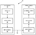
도 1 은 본 개시물의 기법들을 사용할 수도 있는 예시적인 비디오 코딩 시스템을 예시하는 블록도이다.
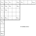
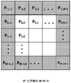
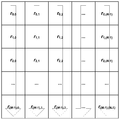
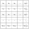
도 2 는 사이즈 M (높이) × N (폭) 의 블록을 예시하는 개념도이다.
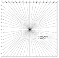
도 3 은 예시적인 인트라 예측 모드 방향들을 예시하는 개념도이다.
도 4 는 비디오 코딩에서의 예측에 사용될 수도 있는 예시적인 샘플들을 예시하는 개념도이다.
도 5a 는 근사-수직 모드들 (near-vertical modes) 에 대한 잔여 차분 펄스 코드 변조 (DPCM) 방향을 나타낸다.
도 5b 는 근사-수평 모드들 (near-horizontal modes) 에 대한 잔여 DPCM 방향을 나타낸다.
도 6 은 본 개시물의 기법들을 구현할 수도 있는 예시적인 비디오 인코더를 예시하는 블록도이다.
도 7 은 본 개시물의 기법들을 구현할 수도 있는 예시적인 비디오 디코더를 예시하는 블록도이다.
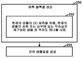
도 8a 는 본 개시물의 하나 이상의 기법들에 따른, 비디오 인코더의 예시적인 동작을 예시하는 플로우차트이다.
도 8b 는 본 개시물의 하나 이상의 기법들에 따른, 비디오 인코더의 예시적인 동작을 예시하는 플로우차트이다.
도 9a 는 본 개시물의 하나 이상의 기법들에 따른, 비디오 디코더의 예시적인 동작을 예시하는 플로우차트이다.
도 9b 는 본 개시물의 하나 이상의 기법들에 따른, 비디오 디코더의 예시적인 동작을 예시하는 플로우차트이다.
도 10a 는 본 개시물의 하나 이상의 기법들에 따른, 부호 데이터 은닉 (sign data hiding) 를 위한 예시적인 비디오 인코더 동작을 예시하는 플로우차트이다.
도 10b 는 본 개시물의 하나 이상의 기법들에 따른, 부호 데이터 은닉을 위한 예시적인 비디오 디코더 동작을 예시하는 플로우차트이다.1 is a block diagram illustrating an exemplary video coding system that may employ techniques of the present disclosure.
2 is a conceptual diagram illustrating a block of size M (height) x N (width).
3 is a conceptual diagram illustrating exemplary intra-prediction mode directions.
4 is a conceptual diagram illustrating exemplary samples that may be used for prediction in video coding.
Figure 5A shows the residual differential pulse code modulation (DPCM) direction for near-vertical modes.
Figure 5B shows the residual DPCM direction for near-horizontal modes.
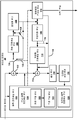
6 is a block diagram illustrating an exemplary video encoder that may implement techniques of the present disclosure.
7 is a block diagram illustrating an exemplary video decoder that may implement techniques of the present disclosure.
8A is a flow chart illustrating an exemplary operation of a video encoder, in accordance with one or more techniques of the present disclosure.
8B is a flow chart illustrating an exemplary operation of a video encoder, in accordance with one or more techniques of the present disclosure.
9A is a flow chart illustrating an exemplary operation of a video decoder, in accordance with one or more techniques of the present disclosure.
9B is a flow chart illustrating an exemplary operation of a video decoder, in accordance with one or more techniques of the present disclosure.
10A is a flow chart illustrating an exemplary video encoder operation for sign data hiding, in accordance with one or more techniques of the present disclosure.
10B is a flow chart illustrating an exemplary video decoder operation for code data concealment in accordance with one or more techniques of the present disclosure.
일반적으로, 본 개시물은 HEVC (High Efficiency Video Coding) 및 다른 비디오 코딩 표준들에서 인트라 예측을 향상시키는 기법들을 기술한다. 인트라 예측은 현재의 화상에서의 샘플 값들에 기초하여, 현재의 화상의 비디오 블록에 대한 예측 블록을 생성하는 프로세스이다. 따라서, 현재의 화상의 비디오 블록이 인트라 예측을 사용하여 인코딩될 때, 비디오 인코더는 비디오 블록에 대한 예측 블록을 생성하거나 또는 아니면 식별하기 위해 다른 화상들로부터의 샘플 값들을 사용하지 않는다.In general, the present disclosure describes techniques for improving intra prediction in High Efficiency Video Coding (HEVC) and other video coding standards. Intra prediction is a process of generating a prediction block for a video block of the current picture, based on sample values in the current picture. Thus, when a video block of the current picture is encoded using intra prediction, the video encoder does not use sample values from other pictures to create or otherwise identify a prediction block for the video block.
예측 블록을 생성한 후, 비디오 인코더는 예측 블록을 사용하여, 잔여 샘플들의 블록 (즉, 잔여 블록) 을 결정할 수도 있다. 잔여 블록에서의 잔여 샘플들은 예측 블록에서의 샘플들과, 비디오 블록의 대응하는 원래 샘플들 사이의 차이를 나타낼 수도 있다. 비디오 인코더는 잔여 블록에 변환을 적용함으로써 변환 계수 블록을 생성할 수도 있다. 이 변환은 잔여 샘플들을 픽셀 도메인으로부터 변환 도메인으로 변환할 수도 있다. 비디오 인코더는 그 후 변환 계수들의 비트 심도들을 감소시키기 위해 변환 계수 블록에서의 변환 계수들을 양자화할 수도 있다. 비디오 인코더는 양자화된 변환 계수들을 나타내는 신택스 엘리먼트들을 엔트로피 인코딩하고, 최종 엔트로피 인코딩된 신택스 엘리먼트들을 비트스트림에 포함시킬 수도 있다.After generating the prediction block, the video encoder may use the prediction block to determine a block of remaining samples (i.e., a residual block). The residual samples in the residual block may represent the difference between the samples in the prediction block and the corresponding original samples in the video block. The video encoder may generate a transform coefficient block by applying a transform to the residual block. This conversion may convert residual samples from the pixel domain to the transform domain. The video encoder may then quantize the transform coefficients in the transform coefficient block to reduce the bit depths of the transform coefficients. The video encoder may entropy encode the syntax elements representing the quantized transform coefficients and may include the final entropy encoded syntax elements in the bitstream.
비디오 디코더는 이 프로세스의 역방향을 수행할 수도 있다. 즉, 비디오 디코더는 비트스트림에서의 신택스 엘리먼트들을 엔트로피 디코딩하여, 양자화된 변환 계수들을 결정할 수도 있다. 비디오 디코더는 그 후 양자화된 변환 계수들을 역양자화하여, 변환 계수들을 결정할 수도 있다. 더욱이, 비디오 디코더는 변환 계수들에 역변환을 적용하여 잔여 블록을 결정할 수도 있다. 게다가, 비디오 디코더는 예측 블록을 (예컨대, 인트라 예측을 사용하여) 결정할 수도 있다. 비디오 디코더는 예측 블록에서의 샘플들 및 잔여 블록에서의 대응하는 잔여 샘플들을 사용하여, 비디오 블록의 샘플들을 재구성할 수도 있다.The video decoder may perform the reverse of this process. That is, the video decoder may entropy-decode the syntax elements in the bitstream to determine the quantized transform coefficients. The video decoder may then dequantize the quantized transform coefficients to determine transform coefficients. Furthermore, the video decoder may apply an inverse transform to the transform coefficients to determine the residual block. In addition, the video decoder may determine the prediction block (e.g., using intra prediction). The video decoder may reconstruct the samples of the video block using samples in the prediction block and corresponding residual samples in the residual block.
변환의 적용 및 양자화의 사용은 정보 손실을 초래한다. 따라서, 비디오 디코더에 의해 재구성된 비디오 블록의 샘플들은 비디오 블록의 원래 샘플들과 동일한 정밀도의 레벨을 갖지 않을 수도 있다. 따라서, 변환의 적용과 양자화의 사용은 "손실" 코딩의 유형일 수도 있다. 일부의 경우, 비디오 인코더는 비디오 블록을 무손실 인코딩을 사용하여 인코딩할 수도 있다. 비디오 인코더가 무손실 인코딩을 사용하여 비디오 블록을 인코딩할 때, 비디오 인코더는 잔여 샘플들에 변환을 적용하지 않고, 잔여 샘플들을 양자화하지 않는다. 이와 유사하게, 비디오 디코더는 역양자화 또는 역변환을 적용하지 않는다. 그 결과, 비디오 디코더에 의해 재구성된 비디오 블록의 샘플들은 비디오 블록의 원래 샘플들과 동일한 정밀도의 레벨을 가질 수도 있다.Application of transformations and use of quantization results in information loss. Thus, the samples of the video block reconstructed by the video decoder may not have the same level of precision as the original samples of the video block. Thus, the application of transformations and the use of quantization may be a type of "lossy " coding. In some cases, the video encoder may encode the video block using lossless encoding. When a video encoder encodes a video block using lossless encoding, the video encoder does not apply a transform to the residual samples and does not quantize the residual samples. Similarly, the video decoder does not apply inverse quantization or inverse transform. As a result, the samples of the video block reconstructed by the video decoder may have the same level of precision as the original samples of the video block.
다른 경우, 비디오 인코더는 비디오 인코더가 잔여 샘플들에 변환을 적용하지 않지만 잔여 샘플들을 양자화하는 일종의 손실 코딩의 유형을 수행할 수도 있다. 이와 유사하게, 비디오 디코더는 잔여 샘플들에 역양자화를 적용하지만, 잔여 샘플들에 역변환을 적용하지 않을 수도 있다. 비디오 인코더가 잔여 샘플들에 여전히 양자화를 적용하기 때문에, 비디오 디코더에 의해 재구성되는 샘플들은 원래 샘플들보다 더 작은 정밀도를 가질 수도 있고, 그러나 정밀도 손실은 변환이 적용된 경우보다 잠재적으로 더 적을 수도 있다.In other cases, the video encoder may perform a type of lossy coding in which the video encoder does not apply transforms to the residual samples but quantizes the residual samples. Similarly, the video decoder applies dequantization to the residual samples, but may not apply an inverse to the residual samples. Because the video encoder still applies quantization to the residual samples, the samples reconstructed by the video decoder may have less precision than the original samples, but the loss of precision may be potentially less than when the transform is applied.
위에서 나타낸 바와 같이, 비디오 코더 (예컨대, 비디오 인코더 또는 비디오 디코더) 는 인트라 예측을 사용하여, 예측 블록을 생성할 수도 있다. 좀더 구체적으로, 비디오 코더는 복수의 가용 인트라 예측 모드들 중에서 특정의 인트라 예측 모드를 사용하여, 예측 블록을 생성한다. HEVC 및 다른 비디오 코딩 표준들에서, 인트라 예측 모드들은 복수의 방향 인트라 예측 모드들, 평면 인트라 예측 모드, 및 DC 인트라 예측 모드를 포함한다. 일반적으로, 비디오 코더가 평면 인트라 예측 모드를 사용하여 예측 블록을 생성할 때, 예측 블록의 샘플들은 선형 투영들 (linear projections) 의 조합에 기초하여 결정될 수도 있다. 비디오 코더가 DC 인트라 예측 모드를 사용하여 예측 블록을 생성할 때, 비디오 코더는 DC 인트라 예측 값을 결정할 수도 있다. DC 인트라 예측 값은 예측 블록의 좌측 에지 및 상부 에지에 인접한 샘플들의 평균 값일 수도 있다. 비디오 코더는 예측 블록에서의 각각의 샘플 값을 DC 인트라 예측 값과 동일하게 설정할 수도 있다.As indicated above, a video coder (e.g., a video encoder or video decoder) may use intra prediction to generate a prediction block. More specifically, the video coder uses a specific intra prediction mode among a plurality of available intra prediction modes to generate a prediction block. In HEVC and other video coding standards, intra prediction modes include a plurality of directional intra prediction modes, a plane intra prediction mode, and a DC intra prediction mode. Generally, when a video coder uses the planar intra prediction mode to generate a prediction block, the samples of the prediction block may be determined based on a combination of linear projections. When the video coder generates the prediction block using the DC intra prediction mode, the video coder may determine the DC intra prediction value. The DC intra prediction value may be the average value of the samples adjacent to the left edge and the upper edge of the prediction block. The video coder may set each sample value in the prediction block equal to the DC intra prediction value.
본 개시물의 일부 기법들은 비디오 코더가 무손실 코딩을 사용할 때 DC 인트라 예측 모드에 대한 향상을 제공한다. 무손실 코딩에서, 비디오 인코더는 DC 인트라 예측 모드를 사용할 때 샘플들의 원래 값들을 사용하여, 예측 블록에서의 샘플들의 값들을 결정할 수도 있다. 손실 코딩에서, 비디오 디코더는 DC 인트라 예측을 사용할 때 샘플들의 원래 값들에 액세스하지 않고 예측 블록에서의 샘플들의 값들을 결정한다. 그러나, 무손실 코딩에서, 비디오 디코더는 DC 인트라 예측을 사용할 때 샘플들의 재구성된 값들에 액세스하여, 예측 블록에서의 값들을 결정한다. 무손실 코딩에서, 샘플들의 재구성된 값들은 샘플들의 원래 값들과 동일하다.Some techniques of the present disclosure provide enhancements to the DC intraprediction mode when the video coder uses lossless coding. In lossless coding, the video encoder may use the original values of the samples when using the DC intra prediction mode to determine the values of the samples in the prediction block. In lossy coding, the video decoder determines the values of samples in the prediction block without accessing the original values of the samples when using DC intra prediction. However, in lossless coding, the video decoder accesses the reconstructed values of the samples when using DC intra prediction, and determines the values in the prediction block. In lossless coding, the reconstructed values of the samples are identical to the original values of the samples.
본원에서 설명하는 바와 같이, 비디오 코더는 예측 블록을 생성할 수도 있다. 예측 블록을 생성하는 것의 일부로서, 비디오 코더는 현재의 샘플의 DC 예측을 위해, 예측 블록의 현재의 로우에서 현재의 샘플의 좌측에 있는 무손실로 재구성된 샘플 및 현재의 로우의 상부에 있는 예측 블록의 로우에 대한 무손실로 재구성된 샘플 중 적어도 하나를 사용할 수도 있다. 더욱이, 일부 경우, 이것은 비디오 디코더로 하여금, 예측 블록에서의 샘플 값들의 결정을 파이프라인 (pipeline) 가능하게 할 수도 있다.As described herein, a video coder may generate a prediction block. As part of generating a prediction block, the video coder uses, for DC prediction of the current sample, a lossless reconstructed sample to the left of the current sample in the current row of the prediction block, Lt; RTI ID = 0.0 > lossless < / RTI > Moreover, in some cases, this may cause the video decoder to pipeline the determination of the sample values in the prediction block.
더욱이, 위에서 나타낸 바와 같이, 비디오 인코더는 변환 스킵 코딩으로서 지칭될 수도 있는, 양자화가 사용되지만 변환은 스킵되는 손실 코딩의 유형을 수행할 수도 있다. 본 개시물의 하나 이상의 추가적인 기법들에 따르면, 비디오 인코더는 잔여 차분 펄스 코드 변조 (DPCM) 의 유형을 적용하여, 코딩을 위해 비-변환되지만 양자화된, 잔여 샘플들을 준비할 수도 있다. 이 유형의 잔여 DPCM 은 본 개시물에서 다른 어딘가에 자세하게 설명된다. 손실 인트라 코딩에서 DPCM 을 사용하는 다른 제안들과는 대조적으로, 본 개시물에서 설명되는 잔여 DPCM 의 이 유형은 비디오 인코더 및/또는 비디오 디코더의 처리량을 증가시킬 수도 있다.Moreover, as indicated above, a video encoder may perform a type of lossy coding, which may be referred to as transform skip coding, in which quantization is used but conversion is skipped. According to one or more additional techniques of the present disclosure, a video encoder may apply the type of residual differential pulse code modulation (DPCM) to prepare non-transformed but quantized residual samples for coding. This type of residual DPCM is described elsewhere elsewhere in this disclosure. In contrast to other proposals using DPCM in lossy intra coding, this type of residual DPCM described in this disclosure may increase the throughput of the video encoder and / or video decoder.
위에서 나타낸 바와 같이, 비디오 인코더는 양자화된 변환 계수들을 나타내는 신택스 엘리먼트들을 엔트로피 인코딩할 수도 있다. 무손실 코딩 또는 손실 코딩에서, 변환이 스킵될 때, 동일한 신택스 엘리먼트들이 잔여 샘플들을 나타내기 위해 사용될 수도 있다. HEVC 및 다른 비디오 코딩 표준들에서, 변환 계수 또는 잔여 샘플을 나타내는 신택스 엘리먼트들은 변환 계수 또는 잔여 샘플이 양인지 또는 음인지 여부를 나타내는 부호 신택스 엘리먼트를 포함할 수도 있다. 일부의 경우, 변환 계수 또는 잔여 샘플이 양인지 또는 음인지 여부를 나타내기 위해 부호 신택스 엘리먼트들을 포함하는 것이 불필요할 수도 있다. 대신, 변환 계수 또는 잔여 샘플이 양인지 또는 음인지 여부를 나타내는 정보가 변환 계수 또는 잔여 샘플에 대한 다른 신택스 엘리먼트들의 값들에 내장될 수도 있다. 부호 신택스 엘리먼트들을 시그널링하는 대신, 이러한 정보를 다른 신택스 엘리먼트들의 값들에 내장하는 것은, 부호 데이터 은닉으로서 지칭될 수도 있다.As indicated above, the video encoder may entropy encode the syntax elements representing the quantized transform coefficients. In lossless coding or lossy coding, when a transformation is skipped, the same syntax elements may be used to represent the residual samples. In HEVC and other video coding standards, syntax elements representing transform coefficients or residual samples may include a code-syntax element indicating whether the transform coefficients or residual samples are positive or negative. In some cases, it may not be necessary to include sign-syntax elements to indicate whether the transform coefficients or residual samples are positive or negative. Instead, information indicating whether the transform coefficients or residual samples are positive or negative may be embedded in the values of the transform coefficients or other syntax elements for the residual samples. Instead of signaling the sign syntax elements, embedding this information in the values of other syntax elements may be referred to as code data concealment.
그러나, 부호 데이터 은닉은, 변환이 스킵되고 평면 인트라 예측 모드, DC 인트라 예측 모드 (예컨대, 예측 블록에서의 샘플들에 대응하는 재구성된 샘플들이 예측 블록에서의 예측 샘플들의 값을 결정하는데 시용되는 DC 인트라 예측 모드), 또는 잔여 DPCM 이 사용되는 손실 코딩을 사용하여 코딩되는 블록들에 대해 구현하는 것이 어려울 수도 있다. 더욱이, 변환 스킵 코딩에서, 부호 데이터 은닉은 잔여 DPCM 이 적용될 때 형성되는 잔여 값들에 에러들을 도입할 수도 있다. 이러한 에러들은 후속 잔여 샘플들로 전파하여, 성능의 열화를 초래할 수도 있다. 따라서, 본 개시물의 하나 이상의 기법들에 따르면, 부호 데이터 은닉은, 부호 데이터 은닉이 이러한 블록들에 대해 인에이블된다고 하나 이상의 신택스 엘리먼트들이 나타내더라도, 이러한 블록들에 대해 규범적으로 디스에이블될 수도 있다.The code data concealment, however, can be performed in such a manner that the transform is skipped and the reconstructed samples corresponding to the planar intra prediction mode, the DC intra prediction mode (e.g., the samples in the prediction block, Intra prediction mode), or for blocks that are coded using lossy coding where residual DPCM is used. Moreover, in the transform skip coding, the code data concealment may introduce errors into the residual values formed when the residual DPCM is applied. These errors may propagate to subsequent residual samples, resulting in degraded performance. Thus, according to one or more of the techniques of this disclosure, code data concealment may be normatively disabled for such blocks, although one or more syntax elements indicate that code data concealment is enabled for these blocks .
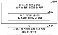
예를 들어, 일부 예들에서, 비디오 디코더는, 현재 블록이 잔여 데이터에 대한 변환의 적용 없이 손실 코딩을 사용하여 생성되고 잔여 DPCM 이 사용되는 인트라 예측 모드를 사용하여 현재 블록이 인트라 예측되면, 부호 데이터 은닉이 현재 블록에 대해 디스에이블된다고 결정한다. 이러한 예들에서, 부호 데이터 은닉이 현재 블록에 대해 디스에이블될 때, 비디오 디코더는 비트스트림으로부터, 블록에서의 각각의 개별의 유효 값 (significant value) 에 대해, 각각의 유효 값이 양인지 또는 음인지 여부를 나타내는 각각의 신택스 엘리먼트를 획득할 수도 있다.For example, in some instances, if the current block is intrapred using the intra prediction mode in which the current block is generated using lossy coding without applying the transform to residual data and the residual DPCM is used, It is determined that the concealment is disabled for the current block. In these examples, when the code data concealment is disabled for the current block, the video decoder, from each bit stream, for each individual significant value in the block, determines whether each valid value is positive or negative ≪ / RTI > may be obtained.
도 1 은 본 개시물의 기법들을 사용할 수도 있는 예시적인 비디오 코딩 시스템 (10) 을 예시하는 블록도이다. 본원에서 설명하는 바와 같이, 용어 "비디오 코더" 는 비디오 인코더들 및 비디오 디코더들 양쪽을 포괄적으로 지칭한다. 본 개시물에서, 용어들 "비디오 코딩" 또는 "코딩" 은 비디오 인코딩 또는 비디오 디코딩을 포괄적으로 지칭할 수도 있다.1 is a block diagram illustrating an exemplary
도 1 에 나타낸 바와 같이, 비디오 코딩 시스템 (10) 은 소스 디바이스 (12) 및 목적지 디바이스 (14) 를 포함한다. 소스 디바이스 (12) 는 인코딩된 비디오 데이터를 생성한다. 따라서, 소스 디바이스 (12) 는 비디오 인코딩 디바이스 또는 비디오 인코딩 장치로서 지칭될 수도 있다. 목적지 디바이스 (14) 는 소스 디바이스 (12) 에 의해 생성된 인코딩된 비디오 데이터를 디코딩할 수도 있다. 따라서, 목적지 디바이스 (14) 는 비디오 디코딩 디바이스 또는 비디오 디코딩 장치로서 지칭될 수도 있다. 소스 디바이스 (12) 및 목적지 디바이스 (14) 는 비디오 코딩 디바이스들 또는 비디오 코딩 장치들의 예들일 수도 있다.As shown in FIG. 1, the
소스 디바이스 (12) 및 목적지 디바이스 (14) 는 데스크탑 컴퓨터들, 모바일 컴퓨팅 디바이스들, 노트북 (예컨대, 랩탑) 컴퓨터들, 태블릿 컴퓨터들, 셋-탑 박스들, 소위 "스마트" 폰들과 같은 전화기 핸드셋들, 텔레비전들, 카메라들, 디스플레이 디바이스들, 디지털 미디어 플레이어들, 비디오 게이밍 콘솔들, 자동차용 컴퓨터들, 또는 기타 등등을 포함한, 광범위한 디바이스들을 포함할 수도 있다.The
목적지 디바이스 (14) 는 인코딩된 비디오 데이터를 소스 디바이스 (12) 로부터 채널 (16) 을 통해 수신할 수도 있다. 채널 (16) 은 인코딩된 비디오 데이터를 소스 디바이스 (12) 로부터 목적지 디바이스 (14) 로 이동시키는 것이 가능한 하나 이상의 매체들 또는 디바이스들을 포함할 수도 있다. 일 예에서, 채널 (16) 은 소스 디바이스 (12) 로 하여금, 인코딩된 비디오 데이터를 직접 목적지 디바이스 (14) 로 실시간으로 송신가능하게 하는 하나 이상의 통신 매체들을 포함할 수도 있다. 이 예에서, 소스 디바이스 (12) 는 무선 통신 프로토콜과 같은 통신 표준에 따라서, 인코딩된 비디오 데이터를 변조할 수도 있고, 변조된 비디오 데이터를 목적지 디바이스 (14) 로 송신할 수도 있다. 하나 이상의 통신 매체들은 무선 및/또는 유선 통신 매체들, 예컨대 무선 주파수 (RF) 스펙트럼 또는 하나 이상의 물리적인 송신 라인들을 포함할 수도 있다. 하나 이상의 통신 매체들은 근거리 네트워크, 광역 네트워크, 또는 글로벌 네트워크 (예컨대, 인터넷) 과 같은, 패킷-기반 네트워크의 일부를 형성할 수도 있다. 채널 (16) 은 라우터들, 스위치들, 기지국들, 또는 소스 디바이스 (12) 로부터 목적지 디바이스 (14) 로 통신을 용이하게 하는 다른 장비와 같은, 여러 유형들의 디바이스들을 포함할 수도 있다.The
또 다른 예에서, 채널 (16) 은 소스 디바이스 (12) 에 의해 생성되는 인코딩된 비디오 데이터를 저장하는 저장 매체를 포함할 수도 있다. 이 예에서, 목적지 디바이스 (14) 는, 예컨대, 디스크 액세스 또는 카드 액세스를 통해 저장 매체에 액세스할 수도 있다. 저장 매체는 Blu-ray 디스크들, DVDs, CD-ROMs, 플래시 메모리, 또는 인코딩된 비디오 데이터를 저장하기 위한 다른 적합한 디지털 저장 매체들과 같은 다양한 로컬-액세스되는 데이터 저장 매체들을 포함할 수도 있다.In another example, the
추가 예에서, 채널 (16) 은 소스 디바이스 (12) 에 의해 생성된 인코딩된 비디오 데이터를 저장하는 파일 서버 또는 또 다른 중간 저장 디바이스를 포함할 수도 있다. 이 예에서, 목적지 디바이스 (14) 는 스트리밍 또는 다운로드를 통해 파일 서버 또는 다른 중간 저장 디바이스에 저장된 인코딩된 비디오 데이터에 액세스할 수도 있다. 파일 서버는 인코딩된 비디오 데이터를 저장하고 그 인코딩된 비디오 데이터를 목적지 디바이스 (14) 로 송신가능한 서버의 형태일 수도 있다. 예시적인 파일 서버들은 (예컨대, 웹사이트용) 웹 서버들, 파일 전송 프로토콜 (FTP) 서버들, NAS (network attached storage) 디바이스들, 로컬 디스크 드라이브들 등을 포함한다.In a further example, the
목적지 디바이스 (14) 는 인터넷 접속과 같은 표준 데이터 접속을 통해 인코딩된 비디오 데이터에 액세스할 수도 있다. 데이터 접속들의 예시적인 유형들은 무선 채널들 (예컨대, Wi-Fi 접속들), 유선 접속들 (예컨대, DSL, 케이블 모뎀, 등), 또는 파일 서버 상에 저장된 인코딩된 비디오 데이터에 액세스하는데 적합한 양쪽의 조합들을 포함할 수도 있다. 파일 서버로부터의 인코딩된 비디오 데이터의 송신은 스트리밍 송신, 다운로드 송신, 또는 이 양쪽의 조합일 수도 있다.The
본 개시물의 기법들은 무선 애플리케이션들 또는 설정들에 한정되지 않는다. 이 기법들은 오버-디-에어 텔레비전 브로드캐스트들, 케이블 텔레비전 송신들, 예컨대, 인터넷을 통한 위성 텔레비전 송신들, 데이터 저장 매체 상의 저장을 위한 비디오 데이터의 인코딩, 데이터 저장 매체 상에 저장된 비디오 데이터의 디코딩, 또는 다른 애플리케이션들과 같은, 다양한 멀티미디어 애플리케이션들의 지원 하에서, 비디오 코딩에 적용될 수도 있다. 일부 예들에서, 비디오 코딩 시스템 (10) 은 비디오 스트리밍, 비디오 플레이백, 비디오 브로드캐스팅, 및/또는 비디오 전화 통신과 같은, 지원 애플리케이션들로의 일방향 또는 양방향 비디오 송신을 지원하도록 구성될 수도 있다.The techniques of the present disclosure are not limited to wireless applications or settings. These techniques include over-the-air television broadcasts, cable television transmissions, such as satellite television transmissions over the Internet, encoding of video data for storage on a data storage medium, decoding of video data stored on a data storage medium , Or in support of various multimedia applications, such as other applications. In some instances,
도 1 의 예에서, 소스 디바이스 (12) 는 비디오 소스 (18), 비디오 인코더 (20), 및 출력 인터페이스 (22) 를 포함한다. 일부 예들에서, 출력 인터페이스 (22) 는 변조기/복조기 (모뎀) 및/또는 송신기를 포함할 수도 있다. 비디오 소스 (18) 은 비디오 캡쳐 디바이스, 예컨대, 비디오 카메라, 이전에-캡쳐된 비디오 데이터를 포함하는 비디오 아카이브, 비디오 콘텐츠 제공자로부터 비디오 데이터를 수신하는 비디오 공급 인터페이스, 및/또는 비디오 데이터를 생성하기 위한 컴퓨터 그래픽스 시스템, 또는 이런 비디오 데이터의 소스들의 조합을 포함할 수도 있다.In the example of FIG. 1, the
비디오 인코더 (20) 는 비디오 소스 (18) 로부터의 비디오 데이터를 인코딩할 수도 있다. 일부 예들에서, 소스 디바이스 (12) 는 인코딩된 비디오 데이터를 목적지 디바이스 (14) 로부터 출력 인터페이스 (22) 를 통해 직접 송신한다. 다른 예들에서, 인코딩된 비디오 데이터는 또한 디코딩 및/또는 플레이백을 위한 목적지 디바이스 (14) 에 의한 추후 액세스를 위해 저장 매체 또는 파일 서버 상으로 저장될 수도 있다.The
도 1 의 예에서, 목적지 디바이스 (14) 는 입력 인터페이스 (28), 비디오 디코더 (30), 및 디스플레이 디바이스 (32) 를 포함한다. 일부 예들에서, 입력 인터페이스 (28) 은 수신기 및/또는 모뎀을 포함한다. 입력 인터페이스 (28) 은 인코딩된 비디오 데이터를 채널 (16) 을 통해 수신할 수도 있다. 디스플레이 디바이스 (32) 는 목적지 디바이스 (14) 와 통합되거나 또는 그 외부에 있을 수도 있다. 일반적으로, 디스플레이 디바이스 (32) 는 디코딩된 비디오 데이터를 디스플레이한다. 디스플레이 디바이스 (32) 는 다양한 디스플레이 디바이스들, 예컨대 액정 디스플레이 (LCD), 플라즈마 디스플레이, 유기 발광 다이오드 (OLED) 디스플레이, 또는 또 다른 유형의 디스플레이 디바이스를 포함할 수도 있다.In the example of FIG. 1, the
도 1 은 단지 예이고, 본 개시물의 기법들은 비디오 인코딩 디바이스와 비디오 디코딩 디바이스 사이의 임의의 데이터 통신을 반드시 포함할 필요가 없는 비디오 코딩 설정들 (예컨대, 비디오 인코딩 또는 비디오 디코딩) 에 적용할 수도 있다. 다른 예들에서, 데이터는 로컬 메모리로부터 취출되어, 네트워크 등을 통해 스트리밍된다. 비디오 인코딩 디바이스는 데이터를 인코딩하여 메모리에 저장할 수도 있거나, 및/또는 비디오 디코딩 디바이스는 메모리로부터 데이터를 취출하여 디코딩할 수도 있다. 많은 예들에서, 비디오 인코딩 및 디코딩은 서로 통신하지 않지만, 메모리에 데이터를 간단히 인코딩하거나 및/또는 메모리로부터 데이터를 취출하여 디코딩하는 디바이스들에 의해 수행된다.Figure 1 is merely an example, and the techniques of the present disclosure may be applied to video coding settings (e.g., video encoding or video decoding) that do not necessarily involve any data communication between the video encoding device and the video decoding device . In other examples, data is retrieved from local memory and streamed over a network or the like. The video encoding device may encode the data and store it in memory, and / or the video decoding device may extract and decode the data from the memory. In many instances, video encoding and decoding do not communicate with each other, but are performed by devices that simply encode data into and / or decode data from memory.
비디오 인코더 (20) 및 비디오 디코더 (30) 각각은 하나 이상의 마이크로프로세서들, 디지털 신호 프로세서들 (DSPs), 주문형 집적 회로들 (ASICs), 필드-프로그래밍가능 게이트 어레이들 (FPGAs), 이산 로직, 하드웨어, 또는 임의의 이들의 조합들과 같은, 다양한 적합한 회로 중 임의의 회로로서 구현될 수도 있다. 기법들이 소프트웨어로 부분적으로 구현되면, 디바이스는 소프트웨어용 명령들을 적합한 비일시적 컴퓨터 판독가능 저장 매체에 저장할 수도 있고, 본 개시물의 기법들을 수행하기 위해 그 명령들을 하드웨어에서 하나 이상의 프로세서들을 사용하여 실행할 수도 있다. (하드웨어, 소프트웨어, 하드웨어와 소프트웨어의 조합 등을 포함한) 전술한 것 중 임의의 것이 하나 이상의 프로세서들로 간주될 수도 있다. 비디오 인코더 (20) 및 비디오 디코더 (30) 각각은 하나 이상의 인코더들 또는 디코더들에 포함될 수도 있고, 이들 중 어느 쪽이든 각각의 디바이스에서 결합된 인코더/디코더 (CODEC) 의 일부로서 통합될 수도 있다.
본 개시물은 일반적으로 어떤 정보를 "시그널링하는" 비디오 인코더 (20) 을 참조할 수도 있다. 용어 "시그널링" 은 일반적으로 압축된 비디오 데이터를 디코딩하는데 사용되는 신택스 엘리먼트들 및/또는 다른 데이터의 통신을 지칭할 수도 있다. 이런 통신은 실시간 또는 거의-실시간으로 일어날 수도 있다. 대안적으로, 이러한 통신은 예컨대, 신택스 엘리먼트들을, 인코딩 시에 인코딩된 비트스트림으로, 컴퓨터 판독가능 저장 매체에 저장할 때 일어날 지도 모르는 어떤 기간에 걸쳐서 일어날 수도 있고, 이 신택스 엘리먼트들은 그 후 이 매체에 저장된 후에 비디오 디코딩 디바이스가 임의의 시간에 취출할 수도 있다.The present disclosure may refer generally to a
일부 예들에서, 비디오 인코더 (20) 및 비디오 디코더 (30) 는 HEVC (High Efficiency Video Coding) 표준과 같은, 비디오 압축 표준에 따라서 동작한다. "HEVC 작업 초안 6" 으로 지칭되는, HEVC 표준의 초안은, ITU-T SG16 WP3 과 ISO/IEC JTC1/SC29/WG11 의 JCT-VC (Joint Collaborative Team on Video Coding), 7차 회의: 2011년 11월, 스위스, 제네바, Bross 등, "High efficiency video coding (HEVC) text specification draft 6" 에 설명되어 있고, 이의 전체 내용이 본원에 참고로 포함된다. 2013년 4월 5일 현재, HEVC 작업 초안 6 은 http: //phenix.int-evry.fr/jct/doc_end_user/documents/8_San%20Jose/wg11/JCTVC-H1003-v22.zip 로부터 다운로드가능하다. "HEVC 작업 초안 9" 로서 지칭되는, HEVC 표준의 또 다른 초안은, ITU-T SG16 WP3 과 ISO/IEC JTC1/SC29/WG11 의 JCT-VC (Joint Collaborative Team on Video Coding), 11차 회의: 2012년, 10월, 중국, 상하이, Bross 등, "HEVC Working Draft 9" 에 설명되어 있고, 이의 전체 내용이 본원에 참고로 포함된다. 2014년 3월 24일 현재, HEVC 작업 초안 9 는 http: //phenix.int-evry.fr/jct/doc_end_user/documents/11_Shanghai/wg11/JCTVC-K1003-v8.zip 로부터 다운로드가능하다. "HEVC 작업 초안 10" 으로서 지칭되는, HEVC 의 또 다른 초안은, ITU-T SG16 WP3 과 ISO/IEC JTC1/SC29/WG11 의 JCT-VC (Joint Collaborative Team on Video Coding), 12차 회의: 2013년 1월 14-23일, 스위스, 제네바, Bross 등, "High Efficiency Video Coding (HEVC) text specification draft 10 (for FDIS & Consent)" 에 설명되어 있고, 이의 전체 내용이 본원에 참고로 포함된다. 2014년 3월 24일 현재, HEVC 작업 초안 10 은 http: //phenix.int-evry.fr/jct/doc_end_user/documents/12_Geneva/wg11/JCTVC-L1003-v20.zip 로부터 입수가능하다. 본 개시물의 기법들은, 그러나, 임의의 특정의 코딩 표준 또는 기법에 한정되지 않는다.In some instances,
더욱이, 범위 확장 사양 (range extension specification) 은 HEVC 에 대해 개발 중에 있다. 범위 확장 사양은 4: 0: 0, 4: 2: 0, 4: 2: 2, 및 4: 4: 4 크로마 샘플링과 같은, 대체 샘플링 모드들에 대해 제공한다. ITU-T SG 16 WP 3 과 ISO/IEC JTC 1/SC 29/WG 11 의 JCT-VC (Joint Collaborative Team on Video Coding), 13차 회의: 2013년 4월 18-26일, 대한민국, 인천, Flynn 등, "High Efficiency Video Coding (HEVC) Range Extensions text specification: Draft 3", (이하, "JCTVC-M1005_v2") 는 HEVC 에 대한 범위 확장 사양의 초안이다. 2014년 3월 24일 현재, JCTVC-M1005_v2 는 http: //phenix.int-evry.fr/jct/doc_end_user/documents/13_Incheon/pending/JCTVC-M1005-v2.zip 로부터 입수가능하다. JCTVC-M1005_v2 의 전체 내용이 참조로 포함된다.Moreover, a range extension specification is under development for the HEVC. The range extension specification provides for alternative sampling modes such as 4: 0: 0, 4: 2: 0, 4: 2: 2, and 4: 4: 4 chroma sampling. Joint Collaborative Team on Video Coding (JCT-VC) of ITU-
위에서 간단히 언급한 바와 같이, 비디오 인코더 (20) 는 비디오 데이터를 인코딩한다. 비디오 데이터는 하나 이상의 화상들을 포함할 수도 있다. 화상들의 각각은 비디오의 일부를 형성하는 정지 화상이다. 비디오 인코더 (20) 가 비디오 데이터를 인코딩할 때, 비디오 인코더 (20) 는 비트스트림을 생성할 수도 있다. 비트스트림은 비디오 데이터의 코딩된 표현을 형성하는 비트들의 시퀀스를 포함할 수도 있다. 비트스트림은 코딩된 화상들 및 연관된 데이터를 포함할 수도 있다. 코딩된 화상은 화상의 코딩된 표현이다. 연관되는 데이터는 시퀀스 파라미터 세트들 (SPSs), 화상 파라미터 세트들 (PPSs), 및 다른 신택스 구조들을 포함할 수도 있다. SPS 는 제로 또는 더 이상의 화상들의 시퀀스들에 적용가능한 파라미터들을 포함할 수도 있다. PPS 는 제로 또는 더 이상의 화상들에 적용가능한 파라미터들을 포함할 수도 있다.As briefly mentioned above,
화상은 SL, SCb 및 SCr 로 나타내는, 3개의 샘플 어레이들을 포함할 수도 있다. SL 은 루마 샘플들의 2차원 어레이 (즉, 블록) 이다. 루마 샘플들은 또한 본원에서 "Y" 샘플들로서 지칭될 수도 있다. SCb 는 Cb 색차 샘플들의 2차원 어레이이다. SCr 은 Cr 색차 샘플들의 2차원 어레이이다. 색차 샘플들은 또한 본원에서 "크로마" 샘플들로서 지칭될 수도 있다. Cb 색차 샘플들은 본원에서 "U 샘플들" 로서 지칭될 수도 있다. Cr 색차 샘플들은 본원에서 "V 샘플들" 로서 지칭될 수도 있다.The image may comprise three sample arrays, denoted S L , S Cb and S Cr . S L is a two-dimensional array (i.e., block) of luma samples. Luma samples may also be referred to herein as "Y" samples. S Cb is a two-dimensional array of Cb color difference samples. S Cr is a two-dimensional array of Cr chrominance samples. Color difference samples may also be referred to herein as "chroma" samples. The Cb color difference samples may also be referred to herein as "U samples ". Cr chrominance samples may be referred to herein as "V samples ".
일부 예들에서, 비디오 인코더 (20) 는 화상의 크로마 어레이들 (즉, SCb 및 SCr) 을 다운샘플링할 수도 있다. 예를 들어, 비디오 인코더 (20) 는 YUV 4: 2: 0 비디오 포맷, YUV 4: 2: 2 비디오 포맷, 또는 4: 4: 4 비디오 포맷을 사용할 수도 있다. YUV 4: 2: 0 비디오 포맷에서, 비디오 인코더 (20) 는 크로마 어레이들이 루마 어레이의 높이의 ½ 및 폭의 ½ 이 되도록, 크로마 어레이들을 다운샘플링할 수도 있다. YUV 4: 2: 2 비디오 포맷에서, 비디오 인코더 (20) 는 크로마 어레이들이 루마 어레이의 폭의 ½ 및 동일한 높이가 되도록, 크로마 어레이들을 다운샘플링할 수도 있다. YUV 4: 4: 4 비디오 포맷에서, 비디오 인코더 (20) 는 크로마 어레이들을 다운샘플링하지 않는다.In some instances,
화상의 인코딩된 표현을 생성하기 위해, 비디오 인코더 (20) 는 코딩 트리 유닛들 (CTUs) 의 세트를 생성할 수도 있다. CTUs 의 각각은 루마 샘플들의 코딩 트리 블록, 크로마 샘플들의 2개의 대응하는 코딩 트리 블록들, 및 코딩 트리 블록들의 샘플들을 코딩하는데 사용되는 신택스 구조들일 수도 있다. 코딩 트리 블록은 샘플들의 NxN 블록일 수도 있다. CTU 는 또한 "트리 블록" 또는 "최대 코딩 유닛" (LCU) 로서 지칭될 수도 있다. HEVC 의 CTUs 는 H.264/AVC 와 같은, 다른 표준들의 매크로블록들과 대략 유사할 수도 있다. 그러나, CTU 는 특정의 사이즈에 반드시 제한되지 않고, 하나 이상의 코딩 유닛들 (CUs) 를 포함할 수도 있다.To generate an encoded representation of the picture, the
화상을 인코딩하는 것의 일부로서, 비디오 인코더 (20) 는 화상의 각각의 슬라이스 (즉, 코딩된 슬라이스들) 의 인코딩된 표현들을 생성할 수도 있다. 코딩된 슬라이스를 생성하기 위해, 비디오 인코더 (20) 는 CTUs 의 시리즈를 인코딩할 수도 있다. 본 개시물은 CTU 의 인코딩된 표현을 코딩된 CTU 로서 지칭할 수도 있다. 일부 예들에서, 슬라이스들의 각각은 정수의 코딩된 CTUs 를 포함한다.As part of encoding an image,
코딩된 CTU 를 생성하기 위해, 비디오 인코더 (20) 는 코딩 트리 블록들을 코딩 블록들, 따라서 이름 "코딩 트리 유닛들" 로 분할하기 위해 CTU 의 코딩 트리 블록들에 관해 쿼드-트리 파티셔닝을 회귀적으로 수행할 수도 있다. 코딩 블록은 샘플들의 NxN 블록이다. CU 는 루마 샘플 어레이, Cb 샘플 어레이 및 Cr 샘플 어레이를 갖는 화상의 루마 샘플들의 코딩 블록 및 크로마 샘플들의 2개의 대응하는 코딩 블록들, 및 코딩 블록들의 샘플들을 코딩하는데 사용되는 신택스 구조들일 수도 있다. 단색 화상들, 또는 별개의 칼라 평면들을 사용하여 코딩되는 화상들에서, CU 는 샘플들의 단일 코딩 블록 및 코딩 블록을 코딩하는데 사용되는 신택스 구조들을 포함할 수도 있다. 비디오 인코더 (20) 는 CU 의 코딩 블록을 하나 이상의 예측 블록들로 파티셔닝할 수도 있다. 예측 블록은 동일한 예측이 적용되는 샘플들의 직사각형 (즉, 정사각형 또는 비-정사각형) 블록일 수도 있다. CU 의 예측 유닛 (PU) 는 루마 샘플들의 예측 블록, 화상의 크로마 샘플들의 2개의 대응하는 예측 블록들, 및 예측 블록 샘플들을 예측하는데 사용되는 신택스 구조들일 수도 있다. 비디오 인코더 (20) 는 CU 의 각각의 PU 의 루마, Cb 및 Cr 예측 블록들에 대한 예측 루마, Cb 및 Cr 블록들을 생성할 수도 있다. 단색 화상들, 또는 별개의 칼라 평면들을 사용하여 코딩되는 화상들에서, CU 는 샘플들의 단일 코딩 블록 및 코딩 블록을 코딩하는데 사용되는 신택스 구조들을 포함할 수도 있다.To generate the coded CTU, the
비디오 인코더 (20) 는 인트라 예측 또는 인터 예측을 사용하여, PU 에 대한 예측 블록들을 생성할 수도 있다. 비디오 인코더 (20) 가 PU 의 예측 블록들을 생성하기 위해 인트라 예측을 사용하면, 비디오 인코더 (20) 는 PU 와 연관되는 화상의 디코딩된 샘플들에 기초하여 PU 의 예측 블록들을 생성할 수도 있다.The
비디오 인코더 (20) 가 PU 의 예측 블록들을 생성하기 위해 인터 예측을 사용하면, 비디오 인코더 (20) 는 PU 와 연관되는 화상 이외의 하나 이상의 화상들의 디코딩된 샘플들에 기초하여, PU 의 예측 블록들을 생성할 수도 있다. 비디오 인코더 (20) 는 PU 의 예측 블록들을 생성하기 위해 단방향-예측 또는 양방향-예측을 사용할 수도 있다. 비디오 인코더 (20) 가 PU 에 대한 예측 블록들을 생성하기 위해 단방향-예측을 사용할 때, PU 는 단일 모션 벡터를 가질 수도 있다. 비디오 인코더 (20) 가 PU 에 대한 예측 블록들을 생성하기 위해 단방향-예측을 사용할 때, PU 는 2개의 모션 벡터들을 가질 수도 있다.If the
비디오 인코더 (20) 가 CU 의 하나 이상의 PUs 에 대한 예측 블록들 (예컨대, 루마, Cb 및 Cr 블록들) 을 생성한 후, 비디오 인코더 (20) 는 CU 에 대한 잔여 블록을 생성할 수도 있다. 예를 들어, 비디오 인코더 (20) 는 CU 에 대한 루마 잔여 블록을 생성할 수도 있다. CU 의 루마 잔여 블록에서의 각각의 샘플은 CU 의 예측 루마 블록들 중 하나에서의 루마 샘플과 CU 의 원래 루마 코딩 블록에서의 대응하는 샘플 사이의 차이를 나타낸다. 게다가, 비디오 인코더 (20) 는 CU 에 대한 Cb 잔여 블록을 생성할 수도 있다. CU 의 Cb 잔여 블록에서의 각각의 샘플은 CU 의 예측 Cb 블록들 중 하나에서의 Cb 샘플과 CU 의 원래 Cb 코딩 블록에서의 대응하는 샘플 사이의 차이를 나타낼 수도 있다. 비디오 인코더 (20) 는 또한 CU 에 대한 Cr 잔여 블록을 생성할 수도 있다. CU 의 Cr 잔여 블록에서의 각각의 샘플은 CU 의 예측 Cr 블록들 중 하나에서의 Cr 샘플과 CU 의 원래 Cr 코딩 블록에서의 대응하는 샘플 사이의 차이를 나타낼 수도 있다.After the
더욱이, 비디오 인코더 (20) 는 쿼드-트리 파티셔닝을 사용하여, CU 의 잔여 블록들을 변환 블록들로 분해할 수도 있다. 예를 들어, 비디오 인코더 (20) 는 쿼드-트리 파티셔닝을 사용하여, CU 의 루마, Cb, 및 Cr 잔여 블록들을 루마, Cb, 및 Cr 변환 블록들로 분해할 수도 있다. 변환 블록은 동일한 변환이 적용되는 샘플들의 직사각형의 블록일 수도 있다. CU 의 변환 유닛 (TU) 는 루마 샘플들의 변환 블록, 크로마 샘플들의 2개의 대응하는 변환 블록들, 및 변환 블록 샘플들을 변환하는데 사용되는 신택스 구조들일 수도 있다. 따라서, CU 의 각각의 TU 는 루마 변환 블록, Cb 변환 블록, 및 Cr 변환 블록과 연관될 수도 있다. TU 와 연관되는 루마 변환 블록은 CU 의 루마 잔여 블록의 서브-블록일 수도 있다. Cb 변환 블록은 CU 의 Cb 잔여 블록의 서브-블록일 수도 있다. Cr 변환 블록은 CU 의 Cr 잔여 블록의 서브-블록일 수도 있다. 단색 화상들, 또는 별개의 칼라 평면들을 사용하여 인코딩되는 화상들에서, TU 는 단일 변환 블록 및 변환 블록 샘플들을 변환하는데 사용되는 신택스 구조들을 포함할 수도 있다. TU 사이즈는 TU 의 변환 블록의 사이즈일 수도 있다.Furthermore, the
비디오 인코더 (20) 는 하나 이상의 변환들을 TU 의 변환 블록에 적용하여, TU 에 대한 계수 블록을 생성할 수도 있다. 예를 들어, 비디오 인코더 (20) 는 하나 이상의 변환들을 TU 의 루마 변환 블록에 적용하여, TU 에 대한 루마 계수 블록을 생성할 수도 있다. 계수 블록은 변환 계수들의 2차원 어레이일 수도 있다. 변환 계수는 스칼라 양일 수도 있다. 또한, 비디오 인코더 (20) 는 하나 이상의 변환들을 TU 의 Cb 변환 블록에 적용하여, TU 에 대한 Cb 계수 블록을 생성할 수도 있다. 비디오 인코더 (20) 는 하나 이상의 변환들을 TU 의 Cr 변환 블록에 적용하여, TU 에 대한 Cr 계수 블록을 생성할 수도 있다.
계수 블록 (예컨대, 루마 계수 블록, Cb 계수 블록, 또는 Cr 계수 블록) 을 생성한 후, 비디오 인코더 (20) 는 계수 블록을 양자화할 수도 있다. 양자화는 일반적으로 변환 계수들을 나타내는데 사용되는 데이터의 양을 가능한 한 감축하기 위해 변환 계수들이 양자화되는 프로세스를 지칭하고, 추가적인 압축을 제공한다. 비디오 인코더 (20) 가 계수 블록을 양자화한 후, 비디오 인코더 (20) 는 양자화된 변환 계수들을 나타내는 신택스 엘리먼트들을 엔트로피 인코딩할 수도 있다. 예를 들어, 비디오 인코더 (20) 는 양자화된 변환 계수들을 나타내는 신택스 엘리먼트들에 관해 컨텍스트-적응 2진 산술 코딩 (CABAC) 를 수행할 수도 있다. 비디오 인코더 (20) 는 엔트로피-인코딩된 신택스 엘리먼트들을 비트스트림으로 출력할 수도 있다.After generating a coefficient block (e.g., a luma coefficient block, a Cb coefficient block, or a Cr coefficient block), the
비디오 디코더 (30) 는 비디오 인코더 (20) 에 의해 생성되는 비트스트림을 수신할 수도 있다. 게다가, 비디오 디코더 (30) 는 비트스트림을 파싱하여, 비트스트림으로부터 신택스 엘리먼트들을 디코딩할 수도 있다. 비디오 디코더 (30) 는 비트스트림으로부터 디코딩된 신택스 엘리먼트들에 적어도 부분적으로 기초하여 비디오 데이터의 화상들을 재구성할 수도 있다. 비디오 데이터를 재구성하는 프로세스는 일반적으로 비디오 인코더 (20) 에 의해 수행되는 프로세스와 반대일 수도 있다. 예를 들어, 비디오 디코더 (30) 는 현재의 CU 의 PUs 에 대한 예측 블록들을 결정하기 위해 PUs 의 모션 벡터들을 사용할 수도 있다. 게다가, 비디오 디코더 (30) 는 현재의 CU 의 TUs 과 연관되는 변환 계수 블록들을 역양자화할 수도 있다. 비디오 디코더 (30) 는 변환 계수 블록들에 관해 역변환들을 수행하여, 현재의 CU 의 TUs 와 연관되는 변환 블록들을 재구성할 수도 있다. 비디오 디코더 (30) 는 현재의 CU 의 PUs 에 대한 예측 블록들의 샘플들을 현재의 CU 의 TUs 의 변환 블록들의 대응하는 샘플들에 가산함으로써, 현재의 CU 의 코딩 블록들을 재구성할 수도 있다. 화상의 각각의 CU 에 대해 코딩 블록들을 재구성함으로써, 비디오 디코더 (30) 는 그 화상을 재구성할 수도 있다.The
위에서 나타낸 바와 같이, 비디오 인코더 (20) 또는 비디오 디코더 (30) 과 같은, 비디오 코더는, 인트라 예측을 사용하여, 현재의 PU 에 대한 예측 블록을 생성할 수도 있다. 비디오 코더가 현재의 PU 에 대한 예측 블록을 생성하기 위해 인트라 예측을 사용할 때, 비디오 코더는 참조 샘플들의 세트를 사용하여 예측 블록에서의 샘플들의 값들을 결정할 수도 있다. 예를 들어, HEVC 인트라 예측에서, 상부 및 좌측면 이웃하는 블록들로부터의 이미 재구성된 샘플들이 예측에 사용될 수도 있다. 이들 재구성된 샘플들은 참조 샘플들로서 지칭될 수도 있다.As indicated above, a video coder, such as
도 2 는 HEVC 인트라 예측을 위한 블록의 참조 샘플들을 예시한다. 다시 말해서, 도 2 는 사이즈 M (높이) × N (폭) 의 블록을 예시하는 개념도이다. 도 2 에서, M 은 로우들을 나타내고, N 은 칼럼들을 나타낸다. 더욱이, 도 2 에서, 블록의 샘플들은 Pi,j 로 나타내어지고, 여기서, 0 ≤ i ≤ (M - 1) 및 0 ≤ j ≤ (N - 1) 이다. 본 개시물에서, 용어 "샘플들" 은 입력 성분 (예컨대, RGB 화상에서의 R, G, 또는 B, YCbCr 화상들에서의 Y, Cb, 또는 Cr, 등) 의 원래 픽셀 값들 또는 칼라 변환을 입력 성분들에 적용한 후 성분의 샘플 값들을 지칭할 수 있다. 도 2 의 예에서, 참조 픽셀들은 P-1,j 로 나타내어지고, 여기서 -1 ≤ j < 2N 이며, Pi,-1 로 나타내어지고, 여기서 -1 ≤ i < 2M 이다.Figure 2 illustrates reference samples of a block for HEVC intra prediction. In other words, Fig. 2 is a conceptual diagram illustrating a block of size M (height) x N (width). In Figure 2, M represents rows and N represents columns. Further, in Fig. 2, the samples of the block are denoted P i, j , where 0 ≤ i ≤ (M - 1) and 0 ≤ j ≤ (N - 1). In the present disclosure, the term "samples" refers to the input of an original pixel value or color transformation of an input component (e.g., R, G, or B in an RGB image, Y, Cb, or Cr in a YCbCr images, May refer to the sample values of the component after it has been applied to the components. In the example of FIG. 2, the reference pixels are denoted P -1, j , where -1? J <2N, denoted P i, -1 , where -1? I <2M.
도 2 의 예에 나타낸 바와 같이, 참조 샘플들은 현재의 PU 의 좌측에 있는 참조 샘플들의 세트 및 현재의 PU 의 상부에 있는 참조 샘플의 세트를 포함할 수도 있다. 본 개시물은 현재의 PU 의 상부에 있는 참조 샘플들의 세트를 상부 예측자로서 지칭할 수도 있다. 본 개시물은 현재의 PU 의 좌측에 있는 참조 샘플들의 세트를 좌측 예측자로서 지칭할 수도 있다. 다시 말해서, HEVC 인트라 예측에서, 상부 및 좌측면 이웃하는 블록들로부터의 이미 재구성된 샘플들이 예측에 사용된다 ("상부" 이웃하는 블록은 또한 "상부" 이웃하는 블록으로서 불려질 수도 있다). 이들 샘플들은 참조 샘플들로서 지칭된다. 일부 예들에서, 참조 픽셀들이 사용불가능하면, HEVC 를 사용하는 비디오 코더는 특정의 패딩 프로세스를 사용하여, 손실된 (missing) 참조 샘플들을 생성할 수도 있다.As shown in the example of FIG. 2, the reference samples may include a set of reference samples on the left side of the current PU and a set of reference samples on top of the current PU. The present disclosure may also refer to a set of reference samples at the top of the current PU as an upper predictor. The present disclosure may refer to the set of reference samples to the left of the current PU as the left predictor. In other words, in HEVC intra prediction, already reconstructed samples from the top and left side neighboring blocks are used for prediction (the "upper" neighboring block may also be referred to as the "upper" neighboring block). These samples are referred to as reference samples. In some instances, if reference pixels are unavailable, the video coder using the HEVC may generate a missing reference sample using a specific padding process.
비디오 코더가 인트라 예측을 사용하여 예측 블록을 생성할 때, 비디오 코더는 복수의 가용 인트라 예측 모드들 중 인트라 예측 모드에 따라서 예측 블록을 생성할 수도 있다. 인트라 예측 모드들은 복수의 방향 (즉, 각도) 인트라 예측 모드들을 포함할 수도 있다. 예를 들어, HEVC 의 일부 버전들에서, 33개의 방향 인트라 예측 모드들이 존재한다. 방향 인트라 예측 모드들의 각각은 상이한 방향에 대응한다. 도 3 은 예시적인 인트라 예측 모드 방향들을 예시하는 개념도이다. 비디오 코더가 방향 인트라 예측 모드에 따라서 예측 블록을 생성할 때, 비디오 코더는 예측 블록의 각각의 샘플 각각에 대해, 방향 인트라 예측 모드에 대응하는 방향에서의 각각의 샘플과 정렬되는 참조 샘플의 값 (또는, 참조 샘플들의 가중치 조합) 을 각각의 샘플에 할당할 수도 있다. 비디오 코더가 방향 (즉, 각도) 인트라 예측 모드를 사용하여 현재 블록에 대한 예측 블록을 생성할 때, 비디오 코더는 각도 인트라 예측을 수행하고 있다고 말해질 수도 있다.When a video coder uses intra prediction to generate a prediction block, the video coder may generate a prediction block according to the intra prediction mode among a plurality of available intra prediction modes. Intra prediction modes may include a plurality of directional (i.e., angle) intra prediction modes. For example, in some versions of HEVC, there are 33 directional intra prediction modes. Each of the directional intra prediction modes corresponds to a different direction. 3 is a conceptual diagram illustrating exemplary intra-prediction mode directions. When the video coder generates a prediction block in accordance with the directional intra prediction mode, the video coder calculates, for each sample of the prediction block, the value of the reference sample aligned with each sample in the direction corresponding to the directional intra prediction mode Or a weighted combination of reference samples) may be assigned to each sample. When the video coder uses the direction (i.e., angle) intra prediction mode to generate a prediction block for the current block, the video coder may be said to be performing an angular intra prediction.
더욱이, HEVC 의 일부 버전들에서, 인트라 예측 모드들은 DC 인트라 예측 모드를 포함한다. 이러한 HEVC 의 버전들에서, 비디오 코더가 DC 인트라 예측을 사용하여 예측 블록을 생성할 때, 비디오 코더는 참조 샘플들의 평균 값을 결정할 수도 있다. 비디오 코더는 그 후 예측 블록에서의 각각의 샘플이 결정된 평균 값을 갖는다고 결정할 수도 있다. 따라서, 비디오 코더가 DC 인트라 예측을 사용하여 예측 블록을 생성할 때, 예측 블록의 모든 샘플들은 동일한 값을 갖는다. 예를 들어, 모든 참조 샘플들이 사용가능하도록, 패딩 프로세스가 완료되었다고 가정한다. 이 예에서, 도 2 의 예에 나타낸 4×4 블록에 대해, DC 예측은 다음과 같이 형성될 수도 있다: Moreover, in some versions of the HEVC, the intra prediction modes include a DC intra prediction mode. In versions of such HEVCs, when a video coder generates a prediction block using DC intra prediction, the video coder may determine the average value of the reference samples. The video coder may then determine that each sample in the prediction block has a determined average value. Therefore, when a video coder generates a prediction block using DC intra prediction, all samples of the prediction block have the same value. For example, assume that the padding process is completed so that all reference samples are available. In this example, for the 4x4 block shown in the example of FIG. 2, the DC prediction may be formed as follows:
![]()
![]()
여기서, >> 는 비트 단위 우측 시프트 동작을 나타낸다.Here, " >> " represents a bitwise right shift operation.
HEVC 의 일부 버전들에서, 인트라 예측 모드들은 평면 인트라 예측 모드를 포함한다. 비디오 코더가 평면 인트라 예측 모드를 사용하여 PU 에 대한 예측 블록을 생성할 때, 비디오 코더는 이웃하는 샘플들의 세트, p[x][y] 를 결정할 수도 있고, 여기서, x = -1, y = -1..nTbs*2-1 및 x = 0..nTbS*2-1, y = -1 이고, 여기서 nTbS 는 현재의 PU 의 사이즈이다. 더욱이, predSamples[x][y] 는 예측 블록의 위치 x, y 에서의 샘플의 값을 나타낼 수도 있다. 비디오 코더는 예측 블록의 샘플들을 다음과 같이 결정할 수도 있다: In some versions of HEVC, intra prediction modes include a planar intra prediction mode. When the video coder uses the plane intra prediction mode to generate a prediction block for the PU, the video coder may determine a set of neighboring samples, p [x] [y], where x = -1, y = -1..nTbs * 2-1 and x = 0..nTbS * 2-1, y = -1, where nTbS is the size of the current PU. Furthermore, predSamples [x] [y] may represent the values of samples at the positions x, y of the prediction block. The video coder may determine the samples of the prediction block as follows:

일반적으로, 평면 인트라 예측 모드가 사용될 때, 예측 블록의 샘플의 값은 그 값의 2개의 선형 내삽들의 평균이다. 제 1 선형 내삽에서, x 의 값들이 예측 블록의 로우를 가로질러 좌측에서 우측으로 증가함에 따라서, 로우의 좌측에 있는 참조 샘플에 부여되는 가중치는 감소하는 반면, 예측 블록의 우상부 모서리의 상부 및 우측에 있는 참조 샘플에 부여되는 가중치는 증가한다. 제 2 선형 내삽에서, y 의 값들이 예측 블록의 칼럼 아래쪽으로 증가함에 따라서, 칼럼의 상부에 있는 참조 샘플에 부여되는 가중치는 감소하는 반면, 예측 블록의 좌하단 모서리의 하측 및 좌측에 있는 샘플에 부여되는 가중치는 증가한다.In general, when a plane intra prediction mode is used, the value of the sample of the prediction block is the average of the two linear interpolations of the value. In the first linear interpolation, as the values of x increase from left to right across the rows of the prediction block, the weights given to the reference samples to the left of the row decrease, while the weights to the upper and lower edges of the upper- The weight given to the reference sample on the right increases. In the second linear interpolation, as the values of y increase toward the bottom of the column of the prediction block, the weights given to the reference samples at the top of the column decrease while the values at the bottom and left of the bottom left corner of the prediction block The weighted value increases.
도 2 의 예에서, 평면 인트라 예측은 샘플들 P-1,j 및 PM,-1 을 사용하여, 수직 방향에서 단방향-선형 예측을 생성할 수도 있고, 여기서 0 ≤ j ≤ (N - 1) 이다. 이와 유사하게, 샘플들 Pi,-1 및 P-1,N 은 수평 방향에서 단방향-선형 예측을 생성하는데 사용될 수도 있고, 여기서 0 ≤ i ≤ (M - 1) 이다. 마지막으로, 이 예에서, 수평 및 수직 예측들은 평균될 수도 있다 (또는, 가능하게는 또 다른 수학적 연산과 결합될 수도 있다). 예를 들어, 평면 예측된 값들이 Ti,j 로 표기된다고 하고, 블록이 정사각형, 즉, M = N 이라고 가정한다. 이 예에서, Ti,j 는 다음과 같이 결정될 수도 있다: In the example of FIG. 2, the plane intra prediction may generate unidirectional-linear prediction in the vertical direction using samples P -1, j and P M, -1 , where 0 ≤ j ≤ (N - 1) to be. Similarly, samples P i, -1 and P -1, N may be used to generate unidirectional-linear predictions in the horizontal direction, where 0 ≤ i ≤ (M - 1). Finally, in this example, the horizontal and vertical predictions may be averaged (or possibly combined with another mathematical operation). For example, suppose the plane predicted values are denoted by T i, j , and the block is square, that is, M = N. In this example, T i, j may be determined as follows:
![]()
![]()
![]()
![]()
![]()
![]()
이 예에서, * 는 곱을 나타내고, >> 는 비트 단위 우측 시프트 동작을 나타내고, 위첨자들 H 및 V 는 수평 및 수직 방향들에서의 예측들을 각각 나타낸다.In this example, * denotes the product, >> denotes the bitwise right shift operation, and superscripts H and V indicate predictions in the horizontal and vertical directions, respectively.
일부의 경우, 비디오 인코더 (20) 및 비디오 디코더 (30) 는 본원에서 설명하는 바와 같이, 무손실 코딩 모드를 구현한다. 일반적으로, 비디오 인코더 (20) 가 블록을 인코딩할 때, 비디오 인코더 (20) 는 (예컨대, 이산 코사인 변환을 사용하여) 변환하고 블록에 대한 잔여 데이터 (즉, 예측 에러) 를 양자화한다. 다시 말해서, 예측 에러가 변환되고 양자화된다. 그러나, 비디오 인코더 (20) 가 무손실 코딩을 사용하여 블록 (예컨대, CU) 를 인코딩할 때, 비디오 인코더 (20) 는 블록에 대한 잔여 데이터에 변환 또는 양자화를 적용하지 않을 수도 있다. 다시 말해서, (예컨대, CU 또는 전체 화상에 대한) 무손실 코딩 모드에서, 변환 및 양자화 단계들은 스킵될 수도 있다. 대신, 비디오 인코더 (20) 는 양자화된 변환 계수들과 동일한 방법으로 잔여 데이터의 샘플 값들을 처리할 수도 있다. 예를 들어, 비디오 인코더 (20) 는 잔여 데이터의 샘플 값들을 나타내는 신택스 엘리먼트들을 엔트로피 디코딩하고 최종 데이터를 비트스트림에 포함시킬 수도 있다. 따라서, 잔여 데이터는 변환 또는 양자화로 인해, 어떤 정보의 손실을 겪지 않는다.In some cases,
이와 유사하게, 비디오 디코더 (30) 가 무손실 인코딩을 사용하여 인코딩되어진 블록 (예컨대, CU) 를 디코딩하는 일부 경우들에서, 비디오 디코더 (30) 는 블록에 대한 잔여 데이터에 역양자화 또는 역변환들을 적용하지 않을 수도 있다. 대신, 비디오 디코더 (30) 는 잔여 데이터의 샘플 값들을 나타내는 신택스 엘리먼트들을 엔트로피 디코딩하고 그 후 잔여 데이터의 샘플 값들에 적어도 부분적으로 기초하여 블록의 샘플 값들을 재구성할 수도 있다.Similarly, in some cases where the
본 개시물의 여러 예시적인 기법들은 무손실 인코딩에 관한 것이다. 본원에서 설명하는 바와 같이, 예측을 위해 이웃하는 블록들로부터의 참조 샘플들을 사용하는 대신, 현재 블록으로부터의 샘플들이 향상된 예측을 위해 사용될 수 있다. 예를 들어, 본 개시물의 여러 예시적인 기법들은 HEVC 표준에서 무손실 코딩을 위해 인트라 DC 예측 모드에 적용가능할 수도 있는 변경들을 기술한다. 더욱이, 본 개시물의 여러 예시적인 기법들은 HEVC 표준에서 무손실 코딩을 위해 인트라 평면 예측 모드에 적용가능할 수도 있는 변경들을 기술한다. 본 개시물의 기법들은 또한 다른 유형들의 예측에 적용가능할 수도 있고, 또한 다른 코딩 표준들에 적용가능할 수도 있다.Various exemplary techniques of the disclosure relate to lossless encoding. As described herein, instead of using reference samples from neighboring blocks for prediction, samples from the current block may be used for enhanced prediction. For example, several exemplary techniques of the present disclosure describe modifications that may be applicable to the intra-DC prediction mode for lossless coding in the HEVC standard. Moreover, several exemplary techniques of the present disclosure describe modifications that may be applicable to the intra-plane prediction mode for lossless coding in the HEVC standard. The techniques of the present disclosure may also be applicable to other types of prediction, and may also be applicable to other coding standards.
무손실 코딩에서, 예측을 위해 이웃하는 블록들로부터의 참조 샘플들을 사용하는 대신, 현재 블록으로부터의 샘플들이 향상된 예측을 위해 사용될 수 있다. 예를 들어, 변환이 스킵될 때 무손실 코딩 모드들 뿐만 아니라 손실 코딩 모드들에 있어 각도 인트라 예측을 위한 기법들은, ITU-T SG 16 WP3 및 ISO/IEC JTC1/SC29/WG11의 JCT-VC (Joint Collaborative Team on Video Coding), 5차 회의, 2011년, 3월 16-23일, 스위스, 제네바, Lan 등, "Intra and inter coding tools for screen contents", 문서 JCTVC-E145 (이하, "JCTVC-E145") 에 제시되어 있다. 더욱이, 무손실 코딩에 있어, 변환 및 양자화 단계들은 스킵되고, 따라서, 인트라 DC 모드를 사용할 때 예측 블록의 샘플들을 결정하는 프로세스를 더 향상시키는 것이 가능할 수도 있다.In lossless coding, instead of using reference samples from neighboring blocks for prediction, samples from the current block may be used for enhanced prediction. For example, the techniques for angular intra prediction in lossy coding modes as well as lossless coding modes when the transform is skipped are described in ITU-
본 개시물의 하나 이상의 기법들에 따르면, 예측 블록의 계산을 위해, 샘플들이 로우들을 따라서 래스터 스캐닝으로 프로세싱되고 있는 것으로 가정될 수도 있다. 그러나, 다른 예들에서, 동일한 기법들이 칼럼들에 따른 래스터 스캐닝으로 (또는, 심지어, 그 기법들의 병렬화의 어떤 잠재성을 상실하지만, 대각선 또는 지그-재그 스캐닝들로) 확장될 수 있다. 어떤 변환 또는 양자화도 무손실 모드에서의 예측 에러에 적용되지 않을 때, 예측 에러 (즉, 잔여) 의 엔트로피 디코딩 이후, 원래 샘플이 무손실로 재구성될 수 있다고 가정될 수도 있다. 그러므로, 무손실 코딩의 맥락에서, 용어 "원래 샘플" 또는 "원래 샘플 값" 은 실제 원래 샘플 값들 또는 재구성된 샘플 값들 (즉, 비-잔여 샘플들) 을 지칭할 수도 있다. 로우들을 따른 래스터 스캐닝으로 인해, 현재의 로우로부터 현재의 샘플의 좌측에 있는 모든 샘플들 뿐만 아니라 이전 로우들로부터의 모든 샘플들도 DC 예측을 위해 사용가능하다. 본 개시물의 하나 이상의 기법들은 DC 인트라 예측 모드를 사용한 인트라 예측을 향상시키기 위해 이것을 사용한다.According to one or more of the techniques of the present disclosure, it may be assumed that for the calculation of a prediction block, the samples are being processed in raster scanning along the rows. However, in other examples, the same techniques can be extended with raster scanning (or even with diagonal or jig-jag scanning), depending on the columns, while losing any potential for parallelization of the techniques. When no transform or quantization is applied to the prediction error in the lossless mode, it may be assumed that after the entropy decoding of the prediction error (i. E., Residual), the original sample can be reconstructed losslessly. Thus, in the context of lossless coding, the terms "original sample" or "original sample value" may refer to actual original sample values or reconstructed sample values (ie, non-residual samples). Due to raster scanning along the rows, not only all samples from the current row to the left of the current sample, but also all samples from the previous row are available for DC prediction. One or more techniques of the present disclosure use this to improve intraprediction using the DC intra prediction mode.
본 개시물은 여러 예시적인 인트라 예측 모드들을 기술한다. 본 개시물의 인트라 예측 모드들은 평면 인트라 예측 모드를 대체할 수 있거나 또는 평면 인트라 예측 모드들로서 이해될 수 있다. 따라서, 본 개시물의 인트라 예측 모드들이 무손실 코딩을 위해 HEVC 에서의 현재의 평면 모드를 대체할 수도 있다. 본 개시물의 예들에서 설명되는 세부 사항들은 본 개시물의 다른 예들의 하나 이상의 세부 사항들과 결합될 수도 있다. 즉, 세부 사항들은 또 다른 예들을 달성하기 위해 매우 다양한 상이한 방법들 중 임의의 방법으로 결합될 수도 있다.The present disclosure describes several exemplary intra prediction modes. Intra prediction modes of the disclosure can replace the planar intra prediction mode or can be understood as planar intra prediction modes. Thus, the intra prediction modes of the present disclosure may replace the current planar mode at the HEVC for lossless coding. The details set forth in the examples of this disclosure may be combined with one or more details of other examples of this disclosure. That is, the details may be combined in any of a wide variety of different ways to achieve other examples.
비디오 코더 (예컨대, 비디오 인코더 (20) 또는 비디오 디코더 (30)) 이 DC 인트라 예측 모드를 사용하여 예측 블록을 생성하는 본 개시물의 일부 예들에 따르면, 비디오 코더는 예측 블록의 샘플들을 래스터 스캐닝 순서로 프로세싱할 수도 있다. 비디오 코더가 예측 블록의 샘플을 프로세싱할 때, 비디오 코더는 예측 블록의 샘플의 인과적 이웃을 사용하여, 샘플에 대한 DC 예측 값을 형성할 수도 있다. 일반적으로, 예측 블록에서 샘플의 인과적 이웃은 이미 결정되어 있는 예측 블록에서의 샘플들에 대응하는 재구성된 샘플들 (예컨대, 비-잔여, 비-예측 샘플들) 의 세트이다. 예를 들면, 예측 블록의 좌상부 샘플로부터 시작해서 로우들을 따라 래스터 스캐닝 순서를 사용할 때, 예측 블록에서 샘플의 인과적 이웃은 샘플의 상부 및 좌측 로케이션들에 대응하는 재구성된 샘플들을 포함할 수도 있다. 하나의 이런 예에서, 비디오 코더가 DC 인트라 예측 모드를 사용하여 예측 블록을 생성할 때, 비디오 코더는 현재의 샘플 Pi,j 에 대한 DC 예측 값, DCi,j 를 다음과 같이 계산할 수도 있고, 여기서 0 ≤ i ≤ (M - 1) 및 0 ≤ j ≤ (N - 1) 이다: According to some examples of the present disclosure in which a video coder (e.g.,
![]()
![]()
또는 유사하게, Or similarly,
![]()
![]()
따라서, 방정식들 (4) 및 (5) 에 있어, 예측 블록에서 각각의 샘플 각각에 대해, 비디오 인코더 (20) 는 각각의 샘플에 대한 DC 인트라 예측 값 (즉, DCi,k) 를, 각각의 샘플의 상부에 있는 샘플 (즉, Pi,j-1) 의 재구성된 값과, 각각의 샘플의 좌측에 있는 샘플의 재구성된 값 (즉, Pi-1,j) 의 평균으로서 결정할 수도 있다. 비디오 인코더 (20) 가 무손실 코딩을 사용하고 있기 때문에, 각각의 샘플의 좌측에 있는 샘플의 재구성된 값 및 각각의 샘플의 상부에 있는 샘플의 재구성된 값은 각각의 샘플의 좌측에 있는 샘플의 원래 값들 및 각각의 샘플의 상부에 있는 샘플의 원래 값과 동일하다. 이와 유사하게, 방정식들 (4) 및 (5) 에 있어, 예측 블록에서 각각의 샘플 각각에 대해, 비디오 디코더 (30) 는 각각의 샘플에 대한 DC 인트라 예측 값 (즉, DCi,k) 를, 각각의 샘플의 상부에 있는 샘플 (즉, Pi,j-1) 의 재구성된 값과, 각각의 샘플의 좌측에 있는 샘플의 재구성된 값 (즉, Pi-1,j) 의 평균으로서 결정할 수도 있다. 비디오 디코더 (30) 가 무손실 코딩을 사용하고 있기 때문에, 각각의 샘플의 상부에 있는 샘플의 재구성된 값 및 각각의 샘플의 좌측에 있는 샘플의 재구성된 값은 각각의 샘플의 상부에 있는 샘플의 원래 값 및 각각의 샘플의 좌측에 있는 샘플의 원래 값과 동일하다.Thus, in equations (4) and (5), for each of the samples in the prediction block, the
참조 샘플들에 대한 래스터 스캐닝 및 패딩 프로세스로 인해, 재구성된 샘플들 Pi,j-1 및 Pi-1,j 는 항상 사용가능할 수도 있다. 다시 말해서, 현재의 샘플의 상부에 있는 샘플 및 현재의 샘플의 좌측에 있는 참조 샘플은 항상 사용가능할 수도 있다. 더욱이, DC 예측 값 DCi,j 를 계산하는데 사용되는 우측 시프팅 동작의 비선형 성질로 인해, 비디오 디코더 (30) 가 다수의 샘플들을 병렬로 프로세싱하기가 어려울 수도 있다. 예를 들어, DCi,j+1 은 ![]()
![]()
![]()
![]()
상기 방정식들에서, Ri,j 는 로케이션 (i,j) 에서의 샘플에 대한 예측 잔여이다. 우측 비트-시프트가 비선형 프로세스이기 때문에, DCi,j 의 계산을 종료하기 전에 DCi,j+1 을 계산하는 방법이 전혀 존재하지 않을 수도 있다. 예를 들어, 비디오 디코더 (30) 가 예측 블록의 다수의 샘플들을 병렬로 프로세싱하는 것이 불가능할 수도 있다.In the above equations, R i, j is the prediction residual for the sample at location (i, j). Right bit-shift, because the non-linear process, a method for calculating a DC i, j + 1 before terminating the computation of DC i, j may not exist at all. For example, it may not be possible for the
비디오 디코더 (30) 가 무손실 코딩을 사용하여 코딩되는 현재 블록의 코딩된 표현을 디코딩할 때, 비디오 디코더 (30) 는 비트스트림으로부터, 현재 블록의 잔여 샘플 값들을 나타내는 신택스 엘리먼트들을 획득할 수도 있다. 따라서, 현재 블록이 무손실 코딩을 사용하여 코딩될 때, 비디오 디코더 (30) 는 현재 블록의 잔여 샘플 값들을 결정하기 위해 역양자화 또는 역변환을 적용할 필요가 없다. 비트스트림으로부터 신택스 엘리먼트들을 획득하는 것은 신택스 엘리먼트들을 엔트로피 디코딩하는 것을 수반할 수도 있다. 따라서, 현재 블록이 무손실 또는 손실 코딩을 사용하여 코딩될 때, 현재 블록의 예측 잔여들 (즉, 예측 에러) 가 엔트로피 디코딩되어 있다고 가정될 수도 있다.When the
따라서, 현재 블록이 무손실 또는 손실 코딩을 사용하여 코딩될 때, 예측 잔여들은, 현재 블록에 대한 예측 블록의 샘플들에 대해 DC 예측 값들을 결정할 때에 비디오 디코더 (30) 가 사용하는 샘플들의 재구성된 값들을 결정할 때에 사용하기 위해 사용가능하다. 예측 잔여들이 이미 엔트로피 디코딩되어 있다고 가정하면, 하나의 샘플 지연으로 상이한 로우들에서의 샘플들의 프로세싱을 파이프라인하는 것이 가능할 수도 있다. 따라서, 본 개시물의 하나 이상의 기법들에 따르면, 비디오 디코더 (30) 는 제 1 로우로부터의 하나의 샘플이 재구성된 이후 샘플들의 제 2 로우의 프로세싱을 시작할 수도 있다. 이러한 방법으로, 비디오 디코더 (30) 는 샘플들의 다수의 로우들을 병렬로 프로세싱할 수도 있다. 그러므로, 예측 블록을 생성하는 것의 일부로서, 비디오 코더는 예측 블록의 상이한 로우들에서 샘플들의 프로세싱을 파이프라인할 수도 있고, 여기서, DC 예측을 위한 하나의 사이클 지연이 예측 블록의 로우들 사이에 존재한다.Thus, when the current block is coded using lossless or lossy coding, the predicted residuals are the reconstructed values of the samples used by the
또 다른 예에서, 비디오 코더 (예컨대, 비디오 인코더 (20) 또는 비디오 디코더 (30)) 은 DC 예측 값 DCi,j 를 다음과 같이 계산할 수도 있고, 여기서 0 ≤ i ≤ (M - 1) 및 0 ≤ j ≤ (N - 1) 이다: In another example, a video coder (e.g.,
![]()
![]()
따라서, 이 예에서, 예측 블록의 각각의 샘플 각각에 대해, 비디오 인코더 (20) 는 각각의 샘플에 대한 DC 예측 값 (즉 DCi,j) 를, 각각의 샘플의 상부에 있는 샘플 (즉, Pi,j-1) 의 재구성된 값과 각각의 샘플의 좌측에 있는 샘플 (즉, Pi-1,j) 의 재구성된 값의 합계, 마이너스, 각각의 샘플의 직 상부 및 좌측에 있는 샘플 (즉, Pi-1,j-1) 의 원래 값으로서 결정할 수도 있다. 이와 유사하게, 예측 블록의 각각의 샘플 각각에 대해, 비디오 디코더 (30) 는 각각의 샘플에 대한 DC 예측 값 (즉 DCi,j) 를, 각각의 샘플의 상부에 있는 샘플 (즉, Pi,j-1) 의 재구성된 값과 각각의 샘플의 좌측에 있는 샘플 (즉, Pi-1,j) 의 재구성된 값의 합계, 마이너스, 각각의 샘플의 직 상부 및 좌측에 있는 샘플 (즉, Pi-1,j-1) 의 재구성된 값으로서 결정할 수도 있다. 무손실 코딩이 사용되고 있기 때문에, 샘플들의 재구성된 값은 샘플들의 원래 값들과 동일하다.Thus, in this example, for each sample of the prediction block, the
이 예에서, 추가적인 로직을 사용함으로써 로우에서의 다수의 샘플 값들을 프로세싱하는 것을 더 간단히 할 수도 있다. 예를 들어, 비디오 코더는 Pi,j 를 기다리지 않고 예측 블록의 현재의 샘플 Pi,j 에 대한 DCi,j+1 을 다음과 같이 계산할 수 있다. DCi,j+1 은 다음과 같이 표현될 수 있다: In this example, it may be simpler to process multiple sample values in the row by using additional logic. For example, the video coder is a DC i, j + 1 for the current sample P i, j of the prediction block without waiting for the P i, j can be calculated as follows: DC i, j + 1 can be expressed as:
![]()
![]()
방정식 (7) 은 다음과 같이 다시 쓸 수도 있다: Equation (7) can be rewritten as:
![]()
![]()
방정식들 (7) 및 (8) 에 있어, ri,j 는 샘플 Pi,j 에 대한 예측 에러 잔여이다. 따라서, 이 예에서, 로케이션 (i,j+1) (즉, DCi,j+1) 에서의 특정의 샘플에 대한 DC 인트라 예측 값의 계산은 특정의 샘플의 좌측에 있는 샘플들의 재구성된 값들에 의존하지 않는다. 대신, 특정의 샘플에 대한 DC 인트라 예측 값 DCi,j+1 의 계산은 직상부의 샘플에 대한 재구성된 값 뿐만 아니라, 현재의 샘플의 좌측에 있는 모든 샘플들, 및 동일한 로우 및 상부에 있는 로우에서의 참조 샘플들에 대한 잔여 값들에 의존할 수도 있다. 이것은 전체 로우에 대한 잔여들이 이미 디코딩되어 있다고 가정하면, (비디오 인코더 (20) 뿐만 아니라) 비디오 디코더 (30) 으로 하여금, 블록의 로우에서의 모든 샘플들에 대한 DC 예측 값들을 병렬로 계산가능하게 할 수도 있다.In equations (7) and (8), r i, j is the prediction error residual for sample P i, j . Thus, in this example, the calculation of the DC intraprediction values for a particular sample at location (i, j + 1) (i.e., DC i, j + 1 ) yields reconstructed values of the samples to the left of the particular sample Lt; / RTI > Instead, the calculation of the DC intraprediction value DC i, j + 1 for a particular sample is based on not only the reconstructed value for the immediately upper sample, but also all the samples to the left of the current sample, May depend on the residual values for the reference samples in the row. This allows the video decoder 30 (as well as the video encoder 20) to calculate the DC predictions for all samples in the row of the block in parallel, assuming that the residuals for the entire row have already been decoded You may.
무손실 코딩이 사용되고 있기 때문에, 샘플들 (즉, Pi,j-1, Pi-1,j, 및 Pi-1,j-1) 의 재구성된 값은 샘플들의 원래 값들과 동일하다. 본 개시물에서 다른 어딘가에 추가로 설명된 바와 같이, 이 기법은 손실 코딩에 적용될 수도 있다. 그 경우, 병렬화를 유지하기 위해, DC 예측을 위해 좌측에 있는 샘플들에 대한 비클리핑된 재구성된 값을 사용하는 것이 필요하다. 상부에 있는 로우로부터의 재구성된 샘플들은 클리핑되거나 또는 클리핑되지 않을 수도 있다. 예를 들어, 8-비트 비디오 시퀀스에 대해, 재구성된 샘플들은 간격 [0, 255] 으로 클리핑된다.Since lossless coding is being used, the reconstructed values of the samples (i.e., P i, j-1 , P i-1, j , and P i-1, j-1 ) are identical to the original values of the samples. As further described elsewhere in this disclosure, this technique may be applied to lossy coding. In that case, to maintain the parallelism, it is necessary to use the uncapped reconstructed values for the samples on the left side for DC prediction. The reconstructed samples from the row at the top may or may not be clipped. For example, for an 8-bit video sequence, the reconstructed samples are clipped to the interval [0, 255].
또 다른 예에서, 좌측, 좌상부, 상부 및 우상부 샘플들이 DC 인트라 예측 값들을 결정할 때에 사용된다. 이 예에서, 비디오 코더는 다음과 같이 예측 블록의 현재의 샘플 Pi,j 에 대한 DC 예측 값 DCi,j 를 계산할 수도 있고, 여기서 0 ≤ i ≤ (M - 1) 및 0 ≤ j ≤ (N - 1) 이다: In another example, the left, top left, top and right top samples are used in determining the DC intra prediction values. In this example, the video coder may compute the DC prediction value DC i, j for the current sample P i, j of the prediction block as follows, where 0 ≤ i ≤ (M - 1) and 0 ≤ j ≤ N-1):
![]()
![]()
또는 유사하게, Or similarly,
![]()
![]()
따라서, 방정식들 (9) 및 (10) 의 예들에 있어, 예측 블록의 각각의 샘플 각각에 대해, 각각의 샘플에 대한 DC 인트라 예측 값 (즉, DCi,j) 는 각각의 샘플의 상부에 있는 재구성된 샘플 (즉, Pi,j-1), 각각의 샘플의 좌측에 있는 재구성된 샘플 (즉, Pi-1,j), 각각의 샘플의 상부 및 좌측에 있는 재구성된 샘플 (즉, Pi-1,j-1), 및 각각의 샘플의 상부 및 우측에 있는 재구성된 샘플 (즉, Pi-1,j+1) 의 평균이다. 무손실 코딩이 사용되고 있기 때문에, 샘플들 (즉, Pi,j-1, Pi-1,j, Pi-1,j-1, 및 Pi-1,j+1) 의 재구성된 값들은 샘플들의 원래 값들과 동일하다.Thus, in the examples of equations (9) and (10), for each of the samples of the prediction block, the DC intraprediction value for each sample (i.e., DC i, j ) ( I. E. , P i-1, j ) at the left of each sample, reconstructed samples at the top and left of each sample (i. E. , P i-1, j-1 ) and the reconstructed samples at the top and right of each sample (i.e., P i-1, j + 1 ). Since lossless coding is being used, reconstructed values of samples (i.e., P i, j-1 , P i-1, j , P i-1, j-1 , and P i-1, j + It is the same as the original values of the samples.
DC 인트라 예측 값들을 결정하는데 방정식들 (9) 또는 (10) 을 사용하는 예들에서, 최종 칼럼 (j = (N - 1), i > 0) 에서의 샘플들에 대해, 우상부 샘플은 사용불가능하다. 이를 극복하기 위해, 비디오 코더는 상부 및 우상부 샘플들 (즉, 각각, Pi-1,j 및 Pi-1,j+1) 이 동일한 값을 가진다고 가정할 수도 있다. 비디오 코더가 DC 인트라 예측 값들을 결정하는데 방정식들 (9) 또는 (10) 을 사용하는 또 다른 예에서, 비디오 코더는 단지 가용 샘플들만을 사용하기 위해 DC 예측을 수정할 수도 있다. 일부 예들에서, 샘플은 샘플이 현재의 슬라이스 또는 화상의 경계들 내에 있지 않거나, 또는 아직 코딩되어 있지 않으면, 사용불가능할 수도 있다.In the examples using equations (9) or (10) to determine the DC intra prediction values, for samples in the last column (j = (N - 1), i> 0) Do. To overcome this, the video coder may assume that the upper and upper right samples (i.e., P i-1, j and P i-1, j + 1, respectively ) have the same value. In another example, where the video coder uses equations (9) or (10) to determine DC intra prediction values, the video coder may modify the DC prediction to use only available samples. In some instances, the sample may be unusable if the sample is not within the boundaries of the current slice or picture, or is not yet coded.
더욱이, 본 개시물의 또 다른 예에 따르면, 비디오 코더는 TU 사이즈보다 작은 블록 사이즈에 대해 DC 인트라 예측을 수행할 수도 있다. 예를 들어, TU 사이즈에 관계없이, 비디오 코더는 2×2 블록들에 대해 DC 인트라 예측을 수행할 수도 있다. 비디오 코더는 예측 블록의 2×2 블록들을 래스터 스캐닝 순서로 프로세싱할 수도 있다. 이 예에서, 샘플들 P2i,2j, P2i,2j+1, P2i+1,2j, 및 P2i+1,2j+1 에 대해, 비디오 코더는 DC 인트라 예측 값들을 다음과 같이 계산한다: Moreover, according to another example of the present disclosure, a video coder may perform DC intra prediction on a block size smaller than TU size. For example, regardless of the TU size, the video coder may perform DC intra prediction on 2x2 blocks. The video coder may process the 2x2 blocks of the prediction block in a raster scanning order. In this example, for the samples P 2i, 2j , P 2i, 2j + 1 , P 2i + 1, 2j , and P 2i + 1, 2j + 1 , the video coder calculates the DC intra prediction values as follows :
![]()
![]()
또는 유사하게, Or similarly,
![]()
![]()
이 예에서, 0 ≤ i ≤ ((M / 2) - 1) 및 0 ≤ j ≤ ((N / 2) - 1) 이고, 여기서, M 은 블록의 높이이고 N 은 블록의 폭이다. 더욱이, 이 예에서, M 및 N 이 둘 다 짝수라고 가정된다. 이 예에서, 비디오 코더는 4개의 샘플들을 병렬로 프로세싱할 수 있다. 이 예에서, 비디오 코더는 2×2 블록의 4개의 샘플들의 각각의 DC 인트라 예측 값들을 병렬로 결정가능할 수도 있다. 유사한 예들에서, 비디오 코더는 2×2 블록들 대신, 4×4 블록들 또는 8×8 블록들을 사용할 수도 있다.In this example, 0? I? (M / 2) -1 and 0? J? (N / 2) -1 where M is the height of the block and N is the width of the block. Moreover, in this example, it is assumed that both M and N are even. In this example, the video coder may process four samples in parallel. In this example, the video coder may be able to determine in parallel the DC intra prediction values of each of the four samples of the 2x2 block. In similar examples, the video coder may use 4x4 blocks or 8x8 blocks instead of 2x2 blocks.
본 개시물의 또 다른 예에 따르면, 정상 DC 예측을 수행한 후 잔여들 사이의 상관이 사용된다. 예를 들어, ri,j 를, HEVC (예컨대, HEVC 작업 초안 10) 에 규정된 바와 같이 DC 인트라 예측을 수행한 후 예측 잔여들이라 하고, 여기서, 0 ≤ i ≤ (M - 1) 및 0 ≤ j ≤ (N - 1) 이다. 예를 들어, ri,j 는 상기 방정식 (1) 에서 설명된 바와 같이 DC 인트라 예측을 4×4 블록에 대해 수행한 후 예측 잔여 값일 수도 있다. 이 예에서, 비디오 코더는 그 후 중간 값들 si,j 를 생성할 수도 있고, 여기서, 0 ≤ i ≤ (M - 1) 및 0 ≤ j ≤ (N - 1) 이다. 비디오 코더는 중간 값들 si,j 를 다음과 같이 생성할 수도 있다: According to another example of the disclosure, a correlation between residues is used after performing normal DC prediction. For example, let r i, j be predicted residuals after performing DC intra prediction as defined in the HEVC (eg, HEVC Working Draft 10), where 0 ≤ i ≤ (M - 1) and 0 ≤ j? (N - 1). For example, r i, j may be a predicted residual value after performing DC intra prediction on a 4 × 4 block as described in Equation (1) above. In this example, the video coder may then generate intermediate values s i, j , where 0 ≤ i ≤ (M - 1) and 0 ≤ j ≤ (N - 1). The video coder may generate intermediate values s i, j as follows:
![]()
![]()
상기 방정식 (13) 에서, 0≤i≤(M-1), 0≤j≤((N/2)-1) 이다.In the above equation (13), 0? I? (M-1) and 0? J? ((N / 2) -1).
비디오 코더는 그 후 수정된 잔여 값들 ti,j 를 다음과 같이 생성할 수도 있고, 여기서 0 ≤ i ≤ (M - 1) 및 0 ≤ j ≤ (N - 1) 이다: The video coder may then generate the modified residual values t i, j , where 0 ≤ i ≤ (M - 1) and 0 ≤ j ≤ (N - 1)
![]()
![]()
방정식 (14) 에서, 0 ≤ i ≤ ((M / 2) - 1) 및 0 ≤ j ≤ (N - 1) 이다.In equation (14), 0? I? ((M / 2) - 1) and 0? J? (N - 1).
비디오 인코더는 표준적인 HEVC (예컨대, HEVC 작업 초안 10) 에서 설명된 바와 같이, 수정된 잔여들, ti,j 를 엔트로피 인코딩할 수도 있다. 디코더 측에서 (예컨대, 비디오 디코더 (30) 에서), 이 프로세스는 역전된다. 예를 들어, 비디오 디코더 (30) 는 다음을 결정할 수도 있고, The video encoder may entropy encode the modified residuals, t i, j , as described in the standard HEVC (eg, HEVC Working Draft 10). On the decoder side (e.g., in the video decoder 30), this process is reversed. For example, the
![]()
![]()
여기서, 0 ≤ i ≤ ((M / 2) - 1) 및 0 ≤ j ≤ (N - 1) 이다. 비디오 디코더 (30) 는 또한 다음을 결정할 수도 있고, Here, 0? I? ((M / 2) - 1) and 0? J? (N - 1). The
![]()
![]()
여기서, 0 ≤ i ≤ ((M - 1) 및 0 ≤ j ≤ ((N / 2) - 1) 이다. 이 예는 M 및 N 이 둘 다 짝수라고 가정한다.Here, 0? I? ((M - 1) and 0? J? ((N / 2) - 1) In this example, it is assumed that both M and N are even.
본 개시물의 또 다른 예에서, 잠재적으로 더 나은 예측자가 간단한 차이를 취하는 대신, 사용될 수 있다. 예를 들어, 비디오 코더는 si,j 를 다음과 같이 결정할 수도 있다: In another example of the disclosure, a potentially better predictor may be used instead of taking a simple difference. For example, the video coder may determine s i, j as follows:
![]()
![]()
![]()
![]()
상기 방정식 (17) 에서, 0≤i<M, 0≤j<(N/2) 이다. 상기 방정식 (18) 에서, 0≤i<M/2, 0≤j<N 이다.In the above equation (17), 0? I <M, 0? J <(N / 2). In the above equation (18), 0? I <M / 2, 0? J <N.
본 개시물의 여러 다른 예들에서 설명되는 기법들이 변환이 스킵될 때 손실 코딩할 때에 DC 인트라 예측 모드를 향상시키기 위해 적용될 수 있다. 다시 말해서, 본 개시물의 여러 다른 예들은 비디오 인코더가 변환 블록의 잔여 샘플들에 변환을 적용하지 않지만 변환 블록의 잔여 샘플들을 양자화할 때 DC 인트라 예측 모드를 향상시키기 위해 적용될 수도 있다. 예를 들어, 상기 단락 [0083] 에서 설명된 예에서, 인과적 이웃이 현재의 샘플에 대한 DC 예측 값을 계산하기 위해 사용된다. 이 예에서, 무손실 코딩의 경우에 행해지는 바와 같이 DC 예측 값을 계산하는데 원래 샘플 값들을 사용하는 대신, 인과적 이웃에서 재구성된 (양자화된) 샘플 값들이 사용될 수도 있다. 변환의 적용이 스킵되기 때문에, 인과적 이웃에서의 재구성된 값들이 사용가능하다. 병렬화 이점들을 유지하기 위해서, 클리핑 동작이 전체 로우에 대한 프로세싱이 완료될 때까지 현재의 로우로부터의 재구성된 값들에 적용되지 않는다는 점에 유의해야 한다. 상부의 로우에 대해서는, 클리핑된 또는 비클리핑된 재구성된 값들이 사용될 수도 있다.The techniques described in various other examples of this disclosure can be applied to improve the DC intraprediction mode when loss coding when a conversion is skipped. In other words, various other examples of the present disclosure may be applied to improve the DC intra prediction mode when the video encoder does not apply the transform to the residual samples of the transform block, but quantizes the residual samples of the transform block. For example, in the example described in the paragraph above, a causal neighbor is used to calculate the DC prediction value for the current sample. In this example, instead of using the original sample values to compute the DC prediction value, as done in the case of lossless coding, reconstructed (quantized) sample values in the causal neighborhood may be used. Since the application of the transform is skipped, reconstructed values in the causal neighborhood are available. Note that to maintain the parallelization benefits, the clipping operation is not applied to the reconstructed values from the current row until processing for the entire row is complete. For upper rows, clipped or non-clipped reconstructed values may be used.
이와 유사하게, 상기 단락 [0092] 에서 설명된 바와 같이, TU 는 더 작은 블록들 (예컨대, 2×2 블록들) 로 분할되고, DC 예측 값이 각각의 더 작은 블록에 대해 계산된다. 무손실 코딩의 경우에 행해지는 바와 같이 DC 예측 값을 계산하는데 원래 샘플 값들을 사용하는 대신, 재구성된 (양자화된) 샘플 값들이 변환이 스킵되는 손실 코딩의 경우에 사용될 수도 있다.Similarly, as described in the paragraph above, the TU is divided into smaller blocks (e.g., 2x2 blocks), and a DC prediction value is calculated for each smaller block. Instead of using the original sample values to compute the DC prediction value as is done in the case of lossless coding, reconstructed (quantized) sample values may be used in the case of lossy coding where the conversion is skipped.
손실 코딩의 기법들은 본 개시물에서 위에서 설명된다. 일부 이러한 기법들에 따르면, Pi,j 가, 원래 샘플 값들을 나타낸다고 가정하고, 여기서 0 ≤ i ≤ (M - 1) 및 0 ≤ j ≤ (N - 1) 이다. 더욱이, Q( Pi,j ) 가 Pi,j 의 양자화된 버전을 나타낸다고 하자. 그 후, 손실 코딩을 사용하는 본 개시물의 추가적인 예에 따라서, 비디오 코더는 DC 예측 값 DCi,j 를 다음과 같이 계산할 수도 있다: The techniques of lossy coding are described above in this disclosure. According to some such schemes, it is assumed that P i, j represents the original sample values, where 0 ≤ i ≤ (M - 1) and 0 ≤ j ≤ (N - 1). Further, let Q (P i, j ) denote the quantized version of P i, j . Then, according to a further example of the present disclosure using lossy coding, the video coder may calculate the DC prediction value DC i, j as follows:
![]()
![]()
방정식 DC1 은 샘플 값들 (즉, Pi,j-1, Pi-1,j, 및 Pi-1,j-1) 이 양자화된 후 역양자화된다는 점을 제외하고는, 상기 방정식 (6) 과 유사하다는 점에 유의한다. 본 개시물은 이러한 샘플들을 원래 샘플들의 양자화된 샘플들 또는 양자화된 버전들로서 지칭할 수도 있다. 따라서, 방정식 DC1 에 있어, 예측 블록의 각각의 샘플 각각에 대해, 비디오 코더는 각각의 샘플에 대한 DC 예측 값을, 각각의 샘플의 상부에 있는 원래 샘플의 양자화된 버전 (즉, Q(Pi,j-1)) 과 각각의 샘플의 좌측에 있는 원래 샘플의 양자화된 버전 (즉, Q(Pi-1,j)) 의 합계, 마이너스, 각각의 샘플의 상부 및 좌측에 있는 원래 샘플의 양자화된 버전 (즉, Q(Pi-1,j-1)) 로서 계산할 수도 있다. 방정식 DC1 에 있어, 유형 Q(Pi,j) 의 항들은 재구성된 샘플들이다. 비디오 코더는 그 후 예측 잔여를 ri,j = Pi,j - DCi,j 로서 계산할 수도 있다. 다시 말해서, 잔여 값 ri,j 는 샘플 값 Pi,j, 마이너스, 대응하는 DC 인트라 예측 값 DCi,j 와 같다. 양자화 및 역양자화 이후 재구성된 잔여는 Q(ri,j) 로 나타내어진다.(6), except that the equation DC1 is dequantized after the sample values (i.e., P i, j-1 , P i-1, j and P i-1, j- . ≪ / RTI > The present disclosure may refer to such samples as quantized samples or quantized versions of the original samples. Accordingly, the equation DC1, for each sample, each of the prediction block, the video coder is a DC prediction value for each sample, each of the upper quantized version of the original samples in the sample (that is, Q (P i , j-1 ) and the quantized version of the original sample to the left of each sample (i.e. Q (P i-1, j )), minus the sum of the original samples at the top and left of each sample May be calculated as a quantized version (i.e., Q (P i-1, j-1 )). In equation DC1, the terms of type Q (P i, j ) are reconstructed samples. The video coder may then calculate the prediction residual as r i, j = P i, j - DC i, j . In other words, the residual value r i, j is equal to the sample value P i, j , minus the corresponding DC intra prediction value DC i, j . The reconstructed residuals after quantization and dequantization are denoted by Q (r i, j ).
이전 단락에서 설명된 예는 디코더 측 상에서 일부 바람직한 처리량 성질들을 가질 수도 있다. 예를 들어, 비디오 디코더 (30) 가 블록의 로우 (또는, 칼럼) 에서의 모든 샘플들에 대해 재구성된 샘플 값들을 동시에 계산하는 것이 가능할 수도 있다. 예를 들어, 비디오 디코더 (30) 는 재구성된 샘플 값들을 다음과 같이 획득할 수도 있다: The example described in the previous paragraph may have some desirable throughput properties on the decoder side. For example, it may be possible for the
![]()
![]()
![]()
![]()
방정식 DC2 에 있어, Q(Pi-1,j) 는 적합하게 클리핑될 수도 있는 재구성된 샘플을 나타낸다. 예를 들어, 재구성된 값을 8 의 입력 비트 심도로 적합하게 클리핑하기 위해, Q(Pi-1,j) 의 값들은 0 과 255 사이에 클리핑된다.In equation DC2, Q (P i-1, j ) represents a reconstructed sample that may be suitably clipped. For example, to properly clone the reconstructed value with an input bit depth of 8, the values of Q (P i-1, j ) are clipped between 0 and 255.
더욱이, 일부 예들에서, Q(Pi-1,j) 의 비-클리핑된 버전들을 사용하는 것이 가능할 수도 있다. 다른 값들, Q(Pi-1,-1) 및 Q(Pi,-1) 은 이전에 재구성된 블록들에 속하고, 이미 클리핑되어 있다. 이러한 예들에서, 방정식 DC2 에서 재구성된 샘플 Q(Pi-1,j) 는 클리핑되지 않지만, 처리량에 영향을 미치지 않고 적합하게 클리핑될 수 있다. 방정식 DC1 에 규정되는 예측은, 비디오 디코더가 재구성을 위해 방정식 DC2 를 사용하면, 단지 근사치이다. 방정식 DC1 에서의 예측은, 클리핑된 버전인, Q(Pi,j-1) 대신, 비클리핑된 버전이 사용되기 때문에, 단지 근사치이다. 이러한 경우, Q(Pi,j-1) 의 비클리핑된 버전은, DC 예측을 발생시켜 인코더와 디코더 사이에 드리프트를 피하기 위해서, 인코더 측 상에서도 또한 사용될 수도 있다. 클리핑된 버전을 사용하는 것이 가능하지만, 그 후 샘플들은 하나하나씩 재구성되어야 할 수도 있고, 이에 따라서 처리량에 영향을 미칠 수도 있다. 이것은, 그 경우, 방정식 DC1 이 재구성을 위해 사용되어야 할 수도 있기 때문이다. 이것은 샘플의 재구성이 샘플의 좌측에 있는 샘플의 재구성의 완료에 의존할 수도 있다는 것을 의미한다. 어떻게 샘플들의 로우가 병렬로 재구성될 수 있는지는 본 개시물에서 설명되었다. 유사한 프로세스가 칼럼에서의 모든 샘플들을 병렬로 재구성하기 위해 뒤이어질 수 있다. 더 적은 병렬성이 요망되면, 합계 항 (summation term) 은 더 작은 청크들로 쪼개질 수도 있고, 이에 의해 처리량을 잠재적으로 감소시키지만 샘플을 재구성하는데 요구되는 추가적인 동작들의 평균 개수를 감소시킬 수도 있다.Moreover, in some instances, it may be possible to use non-clipped versions of Q (P i-1, j ). Other values, Q (Pi -1, -1 ) and Q (Pi , -1 ) belong to previously reconstructed blocks and are already clipped. In these examples, the reconstructed sample Q (Pi -1, j ) in equation DC2 is not clipped, but can be suitably clipped without affecting throughput. The prediction specified in equation DC1 is only approximate if the video decoder uses equation DC2 for reconstruction. The prediction in equation DC1 is only approximate, since a non-clipped version is used instead of the clipped version, Q (P i, j-1 ). In this case, the unclipped version of Q (P i, j-1 ) may also be used on the encoder side to avoid DC drift between the encoder and the decoder. It is possible to use a clipped version, but then the samples may have to be reconfigured one by one, and thus affect throughput. This is because, in that case, the equation DC1 may have to be used for reconstruction. This means that the reconstruction of the sample may depend on the completion of the reconstruction of the sample to the left of the sample. How the rows of samples can be reconstructed in parallel has been described in this disclosure. A similar process can be followed to reconfigure all the samples in the column in parallel. If less parallelism is desired, the summation term may be broken down into smaller chunks, thereby potentially reducing throughput but reducing the average number of additional operations required to reconstruct the sample.
따라서, 위에서 설명된 손실 코딩 예들 중 적어도 일부에서, 비디오 코더는 예측 블록을 생성할 수도 있다. 예측 블록을 생성하는 것의 일부로서, 비디오 코더는 제 1 재구성된 샘플 (예컨대, Q(Pi-1,j)) 및 제 2 재구성된 샘플 (예컨대, Q(Pi,j-1)) 중 적어도 하나를 예측 블록의 현재의 샘플의 DC 예측을 위해 사용할 수도 있다. 제 1 재구성된 샘플은 예측 블록의 현재의 로우에서 현재의 샘플의 좌측에 있는 샘플에 대응할 수도 있다. 제 2 재구성된 샘플은 현재의 로우의 상부에 있는 예측 블록의 로우에서의 샘플에 대응할 수도 있다. 비디오 코더는 예측 블록의 샘플들을 대응하는 잔여 샘플들에 가산함으로써, 손실 코딩을 사용하여 코딩된 코딩 블록을 재구성할 수도 있다.Thus, in at least some of the lossy coding examples described above, the video coder may generate a prediction block. One as part of generating a prediction block, the video coder includes a first reconstructed samples (e.g., Q (P i-1, j)) and a second reconstructed samples (e.g., Q (P i, j-1)) At least one may be used for DC prediction of the current sample of the prediction block. The first reconstructed sample may correspond to a sample to the left of the current sample in the current row of the prediction block. The second reconstructed sample may correspond to a sample in the row of the prediction block at the top of the current row. The video coder may reconstruct the coded coding block using lossy coding by adding the samples of the prediction block to the corresponding residual samples.
더욱이, 위에서 설명된 손실 코딩 예들 중 적어도 일부에서, 비디오 코더는 현재의 샘플의 상부에 있는 샘플에 대응하는 재구성된 값 Q(Pi,j-1) 을 결정할 수도 있다. 게다가, 비디오 코더는 현재의 샘플의 좌측에 있는 샘플에 대응하는 재구성된 값 Q(Pi-1,j) 을 결정할 수도 있다. 비디오 코더는 또한 현재의 샘플의 좌측 및 상부에 있는 샘플에 대응하는 재구성된 값 Q(Pi-1,j-1) 을 결정할 수도 있다. 비디오 코더는 현재의 샘플 Pi,j 에 대한 DC 예측 값 DCi,j 를 다음과 같이 계산할 수도 있다: Moreover, in at least some of the lossy coding examples described above, the video coder may determine a reconstructed value Q (P i, j-1 ) corresponding to the sample at the top of the current sample. In addition, the video coder may determine a reconstructed value Q (P i-1, j ) corresponding to the sample to the left of the current sample. The video coder may also determine a reconstructed value Q (P i-1, j-1 ) corresponding to the samples at the left and top of the current sample. The video coder may calculate the DC prediction value DC i, j for the current sample P i, j as follows:
![]()
![]()
위에서 설명된 손실 코딩 예들 중 적어도 일부에서, 비디오 코더는 Q(Pi,j-1), Q(Pi-1,j), 및 Q(Pi-1,j-1) 중에서의 각각의 재구성된 값 각각에 대해, 각각의 재구성된 값을 다음 방법들 중 하나로 결정할 수도 있다. 첫째, 비디오 코더는 각각의 재구성된 값을, 주어진 샘플에 대한 역양자화된 잔여 값 (예컨대, Q(ri,j)), 플러스, 대응하는 샘플에 대한 DC 예측 값 (예컨대, DCi,j) 로서 결정할 수도 있다. 둘째, 방정식 DC2 에서 설명된 바와 같이, 비디오 코더는 각각의 재구성된 값을, 주어진 샘플의 상부에 있는 샘플들에 대한 역양자화된 잔여 값들의 합계 (예컨대, ![]()
![]()
본 개시물의 또 다른 예는 평면 모드에 있어 예측 프로세스에 대한 변경을 제안한다. 평면 모드에 대한 방정식들 (예컨대, 방정식 (2)) 를 고려하는 경우, 최종 로우로부터의 원래 샘플들이 PM,-1 을 사용하는 대신, 수직 예측을 수행하기 위해 사용되면, 수직 예측이 더 정확할 수도 있다. 이와 유사하게, 최종 칼럼으로부터의 원래 샘플들이 P-1,N 을 사용하는 대신, 수평 예측을 수행하기 위해 사용되면, 수평 예측이 더 정확할 수도 있다. 인트라 평면 모드에서 원래 샘플들의 사용은 본 개시물의 하나 이상의 예들 이면에 숨겨진 기본적인 아이디어이다.Another example of the disclosure suggests a change to the prediction process in planar mode. Considering the equations for the planar mode (e.g., equation (2)), if the original samples from the final row are used to perform a vertical prediction, instead of using P M, -1 , It is possible. Similarly, if original samples from the last column are used to perform a horizontal prediction, instead of using P -1, N , the horizontal prediction may be more accurate. The use of original samples in intra planar mode is a fundamental idea hidden behind one or more examples of the present disclosure.
예를 들어, 비디오 인코더 (예컨대, 비디오 인코더 (20)) 은 최종 로우 및 칼럼에 대한 HEVC 평면 예측 (예컨대, HEVC 작업 초안 10 에서 설명된 바와 같은 평면 예측), 즉, Ti,j 를 사용할 수도 있고, 여기서 i = (M - 1) 또는 j = (N - 1) 이다. 비디오 코더는 원래 샘플 값들로부터 예측 값들을 감산하여, 최종 로우 및 칼럼에 대한 잔여들을 생성할 수도 있다. 즉, 비디오 인코더는 ri,j 를 결정할 수도 있고, 여기서 i = (M - 1) 또는 j = (N - 1) 이다. 비디오 인코더는 그 후 예측 값들 Ti,j 를 다음과 같이 생성할 수도 있고, 여기서 0 ≤ i ≤ (M - 2) 및 0 ≤ j ≤ (N - 2) 이다: For example, a video encoder (e.g., video encoder 20) may use HEVC plane prediction (e.g., a flat prediction as described in HEVC Task Draft 10), i.e., T i, j , for the final row and column , Where i = (M - 1) or j = (N - 1). The video coder may subtract the prediction values from the original sample values to generate the residuals for the final row and column. That is, the video encoder may determine r i, j , where i = (M - 1) or j = (N - 1). The video encoder may then generate predicted values T i, j , where 0 ≤ i ≤ (M - 2) and 0 ≤ j ≤ (N - 2)
![]()
![]()
![]()
![]()
![]()
![]()
이 예는 M = N 이라고 가정한다. 그러나, 직사각형의 블록들에 대한 이 개념의 확장은 직접적이다 (straightforward). 비디오 인코더는 원래 샘플 값들로부터 예측 값들을 감산함으로써 나머지 잔여들, ri,j 를 생성할 수도 있고, 여기서 0 ≤ i ≤ (M - 2) 및 0 ≤ j ≤ (N - 2) 이다. 비디오 인코더는 HEVC (예컨대, HEVC 작업 초안 10) 에서와 같이 잔여들, ri,j 의 전체 블록을 엔트로피 인코딩할 수도 있고, 여기서 0 ≤ i ≤ (M - 1) 및 0 ≤ j ≤ (N - 1) 이다.This example assumes M = N. However, the extension of this concept to rectangular blocks is straightforward. The video encoder may generate residuals r i, j by subtracting the prediction values from the original sample values, where 0 ≤ i ≤ (M - 2) and 0 ≤ j ≤ (N - 2). The video encoder may entropy encode the entire block of remainder, r i, j , as in HEVC (eg, HEVC Task Draft 10), where 0 ≤ i ≤ (M - 1) and 0 ≤ j ≤ 1).
이 예에서, 디코더 측 상에서, 비디오 디코더 (예컨대, 비디오 디코더 (30)) 은 예측 잔여들의 전체 블록을 엔트로피 디코딩하여 잔여 값들 ri,j 를 생성할 수도 있고, 여기서 0 ≤ i ≤ (M - 1) 및 0 ≤ j ≤ (N - 1) 이다. 비디오 디코더는 그 후 블록의 최종 로우 및 칼럼에서의 샘플들에 대해 HEVC 평면 예측을 수행할 수도 있다. 즉, 비디오 코더는 HEVC (예컨대, HEVC 작업 초안 10) 에 규정된 바와 같이 Ti,j 를 결정할 수도 있고, 여기서 i = (M - 1) 또는 j = (N - 1) 이다. 예를 들어, 비디오 코더는 상기 방정식 (3) 을 사용하여 Ti,j 를 결정할 수도 있다. 더욱이, 이 예에서, 비디오 디코더는 최종 로우 및 칼럼에 대한 잔여 값들을 상기 예측 값들에 가산하여, 최종 로우 및 칼럼에 대한 원래 샘플 값들을 재구성할 수도 있다. 그 후, 비디오 디코더는 정확히 상기 인코더 측 상에서와 같이 예측 값들 Ti,j 를 생성하고, 여기서, 0 ≤ i ≤ (M - 2) 및 0 ≤ j ≤ (N - 2) 이다. 비디오 디코더는 잔여 값들 ri,j 를, 예측 값들에 가산하여, 블록에서의 나머지 샘플 위치들에 대한 샘플 값들을 재구성하고, 여기서 0 ≤ i ≤ (M - 2) 및 0 ≤ j ≤ (N - 2) 이다.In this example, on the decoder side, a video decoder (e.g., video decoder 30) may entropy-decode an entire block of predicted residuals to produce residual values r i, j , where 0 ≤ i ≤ ) And 0? J? (N - 1). The video decoder may then perform HEVC plane prediction on the samples in the final row and column of the block. That is, the video coder may determine T i, j as defined in the HEVC (eg, HEVC Working Draft 10), where i = (M - 1) or j = (N - 1). For example, the video coder may determine T i, j using equation (3) above. Moreover, in this example, the video decoder may add the residual values for the final row and column to the prediction values to reconstruct the original sample values for the final row and column. The video decoder then produces predicted values T i, j exactly as on the encoder side, where 0 ≤ i ≤ (M - 2) and 0 ≤ j ≤ (N - 2). The video decoder reconstructs the sample values for the remaining sample positions in the block by adding residual values r i, j to the predicted values, where 0 ≤ i ≤ (M - 2) and 0 ≤ j ≤ (N - 2).
본 개시물의 또 다른 예에서, (비디오 인코더 (20) 과 같은) 비디오 인코더는 최종 로우 및 칼럼 상에서의 엘리먼트에 대한 HEVC 평면 예측 (예컨대, HEVC 작업 초안 10 에서 설명된 바와 같은 평면 예측), 즉, Ti,j 를 사용하고, 여기서, i = (M - 1) 및 j = (N - 1) 이다. 이 예에서, 비디오 인코더는 그 위치에 대한 원래 샘플 값으로부터 그 위치에 대한 예측 값을 감산하여, 그 위치에 대한 잔여 값을 생성한다. 비디오 인코더는 그 후 최종 로우 및 칼럼의 엘리먼트들을 다음과 같이 이중 선형적으로 (bilinearly) 예측할 수도 있다: In another example of the present disclosure, a video encoder (such as video encoder 20) may generate an HEVC plane prediction (e.g., a flat prediction as described in HEVC Task Draft 10) for the last row and an element on the column, T i, j , where i = (M - 1) and j = (N - 1). In this example, the video encoder subtracts the predicted value for that location from the original sample value for that location and generates a residual value for that location. The video encoder may then bilinearly predict the final row and column elements as follows:

더욱이, 이 예에서, 비디오 인코더는 예측 값들 Ti,j 를 다음과 같이 생성하고, 여기서 0 ≤ i ≤ (M - 2) 및 0 ≤ j ≤ (N - 2) 이다: Furthermore, in this example, the video encoder generates predicted values T i, j , where 0 ≤ i ≤ (M - 2) and 0 ≤ j ≤ (N - 2)
![]()
![]()
![]()
![]()
![]()
![]()
이 예에서, 비디오 인코더는 원래 샘플 값들로부터 예측 값들을 감산함으로써 잔여 값들 ri,j 를 생성하고, 여기서 0 ≤ i ≤ (M - 1) 및 0 ≤ j ≤ (N - 1) 이다. 더욱이, 이 예에서, 비디오 인코더는 HEVC (예컨대, HEVC 작업 초안 10) 에서와 같이 잔여들, ri,j 의 전체 블록을 엔트로피 디코딩하고, 여기서 0 ≤ i ≤ (M - 1) 및 0 ≤ j ≤ (N - 1) 이다.In this example, the video encoder produces residual values r i, j by subtracting the predicted values from the original sample values, where 0 ≤ i ≤ (M - 1) and 0 ≤ j ≤ (N - 1). Moreover, in this example, the video encoder entropy decodes the entire block of remainders, r i, j , as in HEVC (eg, HEVC task draft 10), where 0 ≤ i ≤ (M - 1) and 0 ≤ j (N - 1).
본 개시물의 또 다른 예는 이전 예들에 대한 개선을 제공한다. 이 예에서, 본 개시물의 예측 기법들로 인한 잔여 배포는 변환이 채용될 때 비디오 압축에서의 일반적인 방향 (common one) 의 역방향인 경향이 있다. 일반적으로, 잔여는 낮은 주파수들에서 더 높은 값들을, 그리고 높은 주파수들에서 높은 예상된 값들을 갖는다. 상기 예들로부터 유래하는 잔여에 대해, 최종 로우 및 칼럼은 더 큰 값들을 갖는 경향이 있다. 변환 잔여를 위해 설계되는 엔트로피 코딩 방법의 이점을 취하면서 성능을 향상시키는 접근법은 위에서 제공된 예들에서 예측으로부터 유래하는 잔여를 회전시키는 것이다. 즉, 잔여는 180 도 회전되고, 따라서 좌상부 부분이 우하측이 되고, 반대의 경우도 마찬가지이다. 그 후, 이 회전된 잔여는 엔트로피 코딩된다. 대응하여, 디코더에서, 잔여가 획득되고 그 후 180 도로 회전된다.Another example of the disclosure provides an improvement over previous examples. In this example, the residual distribution due to the prediction techniques of this disclosure tends to be a common one in video compression when the transform is employed. In general, the remainder have higher values at lower frequencies and higher expected values at higher frequencies. For the remainder resulting from the above examples, the final row and column tend to have larger values. Taking advantage of the entropy coding method designed for transform re- mains, an approach to improving performance is to rotate the remainder resulting from the prediction in the examples provided above. That is, the remainder is rotated by 180 degrees, so that the upper left portion becomes the lower right side, and vice versa. This rotated residue is then entropy coded. Correspondingly, at the decoder, the remainder is acquired and then rotated 180 degrees.
본 개시물의 다른 예들에서, 평면 예측 프로세스는 다음과 같이 수정된다. 제 1 로우 및 칼럼에 대해, 예측은 Ti,j 및 ri,j 를 생성하기 위해 HEVC 평면 모드 (예컨대, HEVC 작업 초안 10 에서 설명된 바와 같은 평면 모드) 의 경우에서 처럼 수행되고, 여기서, i = 0 또는 j = 0 이다. 이 예에서, 제 1 로우 및 칼럼에 대한 예측을 생성하는데 HEVC 방법 (예컨대, HEVC 작업 초안 10, 방정식 (3), 등에서 설명되는 방법) 을 사용하는 대신, 다른 방법들이 사용된다. 예를 들어, P0,0 은 (P-1,0+P0,-1+1)>>1 로서 예측될 수 있다. 제 1 칼럼에서 나머지 샘플들은 동일한 로우에서의 좌측 샘플을 사용하여 예측될 수 있다. 이와 유사하게, 제 1 로우에서 나머지 샘플들은 동일한 칼럼에서의 상부 샘플을 사용하여 예측될 수 있다. 나머지 위치들에 대해, 평면 예측, Ti,j 는 다음과 같이 생성되고, 여기서 1 ≤ i ≤ (M - 1) 및 1 ≤ j ≤ (N - 1) 이다: In other examples of this disclosure, the planar prediction process is modified as follows. For the first row and column, the prediction is performed as in the case of an HEVC plane mode (e.g., a planar mode as described in HEVC Task Draft 10) to generate T i, j and r i, j , i = 0 or j = 0. In this example, instead of using the HEVC method (e.g., the method described in
![]()
![]()
![]()
![]()
![]()
![]()
방정식 (22) 에서, wv 및 wh 는 가중치들이다. 일부 예들에서, 0.5 의 값이 비트-시프트로서 구현될 수 있으므로, 0.5 의 값이 wv 및 wh 양쪽에 대해 사용된다. 나머지 잔여들 (즉, ri,j) 는 원래 샘플 값들로부터 예측 값을 감산함으로써 생성되고, 여기서 1 ≤ i ≤ (M - 1) 및 1 ≤ j ≤ (N - 1) 이다. 잔여들 (즉, ri,j) 의 전체 블록은 HEVC (예컨대, HEVC 작업 초안 10) 에서와 같이 엔트로피 코딩될 수도 있고, 여기서 0 ≤ i ≤ (M - 1) 및 0 ≤ j ≤ (N - 1) 이다.In equation (22), w v and w h are weights. In some instances, a value of 0.5 is used for both w v and w h since a value of 0.5 can be implemented as a bit-shift. The remaining remainder (i.e., r i, j ) is generated by subtracting the predicted value from the original sample values, where 1 ≤ i ≤ (M - 1) and 1 ≤ j ≤ (N - 1). The entire block of remainders (i.e., r i, j ) may be entropy coded as in HEVC (eg, HEVC Task Draft 10) where 0 ≤ i ≤ (M - 1) and 0 ≤ j ≤ 1).
이 예에서, 디코더 측 상에서, 비디오 디코더 (예컨대, 비디오 디코더 (30)) 은 예측 잔여들의 전체 블록을 엔트로피 디코딩하여 잔여 값들 (즉, ri,j) 를 생성할 수도 있고, 여기서 0 ≤ i ≤ (M - 1) 및 0 ≤ j ≤ (N - 1) 이다. 그 후, 비디오 디코더는 비디오 인코더에 의해 사용되는 임의의 다른 방법에 의해, HEVC (예컨대, HEVC 작업 초안 10) 에 규정된 바와 같이 또는 위에서 설명한 바와 같이, 제 1 로우 및 칼럼에서의 샘플들에 대한 평면 예측 (즉, Ti,j) 를 수행하고, 여기서, i = 0 또는 j = 0) 이다. 더욱이, 이 예에서, 비디오 디코더는 제 1 로우 및 칼럼에 대한 잔여 값들을 상기 예측 값들에 가산하여, 제 1 로우 및 칼럼에 대한 원래 샘플 값들을 재구성한다. 그 후에, 비디오 디코더는 정확히 상기 인코더 측 상에서와 같이 예측 값들 (즉, Ti,j) 를 생성하고, 여기서 1 ≤ i ≤ (M - 1) 및 1 ≤ j ≤ (N - 1) 이다. 이 예에서, 비디오 디코더는 잔여 값들 (즉, ri,j) 를 예측 값들에 가산하여, 블록에서의 나머지 위치들에 대한 샘플 값들을 재구성하고, 여기서 1 ≤ i ≤ (M - 1) 및 1 ≤ j ≤ (N - 1) 이다.In this example, on the decoder side, a video decoder (e.g., video decoder 30) may entropy-decode an entire block of predicted residuals to generate residual values (i.e., r i, j ) (M - 1) and 0? J? (N - 1). The video decoder may then decode, by any other method used by the video encoder, for the samples in the first row and column, as defined in the HEVC (e.g., HEVC Task Draft 10) (I.e., T i, j ), where i = 0 or j = 0. Moreover, in this example, the video decoder adds the residual values for the first row and column to the prediction values to reconstruct the original sample values for the first row and column. Thereafter, the video decoder produces exactly the predicted values (i.e., T i, j ) as on the encoder side, where 1 ≤ i ≤ (M - 1) and 1 ≤ j ≤ (N - 1). In this example, the video decoder adds the residual values (i.e., r i, j ) to the predicted values, reconstructing the sample values for the remaining positions in the block, where 1 ≤ i ≤ (M - 1) ≤ j ≤ (N - 1).
상기 단락들은 무손실 코딩을 위해 평면 예측을 수행하는 상이한 방법을 기술한다. 본 개시물의 추가적인 예에서, 최우측 칼럼 및 하부 로우는 HEVC (예컨대, HEVC 작업 초안 10) 에서 설명된 바와 같이 평면 예측 프로시저를 사용하여 예측된다. 이 예에서, 최우측 칼럼 및 하부 로우에 대한 원래 샘플 값들은 그 후 블록의 나머지 샘플들에 대한 평면 또는 각도 예측을 수행하는데 사용된다. 손실 코딩의 경우에 변환이 스킵될 때, 최우측 칼럼 및 하부 로우에 대한 원래 샘플 값들을 사용하는 대신, 재구성된 (양자화된) 샘플 값들이 나머지 샘플들에 대해 평면 또는 각도 예측을 수행하기 위해 사용될 수도 있다.The paragraphs describe different methods of performing a plane prediction for lossless coding. In a further example of the disclosure, the rightmost column and the bottom row are predicted using the planar prediction procedure as described in the HEVC (e.g., HEVC Working Draft 10). In this example, the original sample values for the rightmost column and the bottom row are then used to perform a plane or angular prediction on the remaining samples of the block. Instead of using the original sample values for the rightmost column and the bottom row when the transform is skipped in case of lossy coding, reconstructed (quantized) sample values may be used to perform a plane or angular prediction on the remaining samples It is possible.
HEVC (예컨대, HEVC 작업 초안 10) 에서, 제 1 로우 및 칼럼에 대한 DC 예측 값들이 필터링된다 (DC 예측 필터링). 이와 유사하게, 수평 및 수직 인트라 예측 모드들에 대해, 예측 값들의 제 1 로우 및 칼럼이, 각각, 필터링된다 (그레디언트 필터링 (gradient filtering)). 위에서 설명된 방법들이 DC, 수평 또는 수직 인트라 예측 모드들에 대한 손실 코딩에 적용될 때, 그리고 변환이 스킵될 때, DC 예측 필터링 또는 그레디언트 필터링은 스킵될 수도 있다.In the HEVC (e.g., HEVC Working Draft 10), DC prediction values for the first row and column are filtered (DC prediction filtering). Similarly, for horizontal and vertical intra prediction modes, the first row and column of prediction values are each filtered (gradient filtering). DC prediction filtering or gradient filtering may be skipped when the methods described above are applied to lossy coding for DC, horizontal or vertical intra prediction modes, and when the transform is skipped.
본 개시물의 또 다른 예에서, 평면 예측 모드를 변경하는 대신, 동일한 개념이 각도 인트라 예측 모드들에 적용된다. 각각의 각도 모드에 대해, 최종 로우 및 칼럼은 HEVC (예컨대, HEVC 작업 초안 10, 방정식 (3), 등) 에 규정된 바와 같이 예측된다. 그 후, 최종 로우 및 칼럼에 대한 원래 샘플 값들은 참조 샘플들에 더해서 인트라 예측을 수행하는데 사용된다. 도 4 는 예측을 위해 사용되는 샘플들을 나타낸다. 도 4 에서 음영처리된 위치들은 예측을 수행하기 위해 참조 샘플들로서 사용되는 위치들이다. 특정의 예측 방향 및 특정의 위치에 대해, 참조 샘플들 P-1,j, (또는, 그들의 이중선형 내삽) 이, 예측 값으로서 사용되었더라면, 우측 칼럼으로부터의 원래 샘플 값들 (즉, Pi,N-1) 이 대신 사용되고, 여기서 N ≤ j ≤ 2N 이고, 0 ≤ i ≤ M - 1) 이다. 예측 각도가 최우측 칼럼을 인터셉트하는 위치가 작은 부분 (fraction) 이면, 이중선형 내삽법 또는 임의의 다른 적합한 내삽 방법이 사용될 수도 있다. 일 예로서, 4×4 블록을 고려한다. 인트라 예측 모드 (34) 에 있어, 샘플 (2, 2) 에 대해, 대응하는 참조 샘플은 P-1,6 일 것이다. 따라서, 모드 (34) 에 있어, HEVC 예측은 T2,2 = P-1,5 일 것이다. 대신, 이 예에서, T2,2 = P1,3 이다.In another example of the present disclosure, instead of changing the planar prediction mode, the same concept applies to the angular intra prediction modes. For each angular mode, the final row and column are predicted as specified in the HEVC (e.g.,
이와 유사하게, 특정의 예측 방향 및 특정의 위치에 대해, 참조 샘플들 Pi,-1, (또는, 그들의 이중선형 내삽) 이 예측 값들로서 사용되었으면, 하부 로우로부터의 원래 샘플 값들 (즉, PM-1,j) 가 대신 사용되고, M ≤ i ≤ 2M 이고, 0 ≤ j ≤ N - 1) 이다. 예측 각도가 하부 로우를 인터셉트하는 위치가 작은 부분이면, 이중선형 내삽법 또는 또 다른 적합한 내삽 기법이 사용될 수도 있다. 일 예로서, 4×4 블록을 고려한다. 이 예에서, 인트라 예측 모드 2 에 있어, 샘플 (2, 1) 에 대해, 대응하는 참조 샘플은 P4,-1 이다. 따라서, 모드 2 에 대한 HEVC 예측은 T2,1 = P4,-1 일 것이다. 대신, 이 예에서, T2,1 = P3,0 이다.Similarly, for a particular prediction direction and a particular position, if reference samples P i, -1 , (or their double linear interpolation) were used as prediction values, the original sample values from the lower row (i.e., P M-1, j ) is used instead, M ≤ i ≤ 2M and 0 ≤ j ≤ N-1. If the predicted angle is a small portion where the lower row intercepts, double linear interpolation or another suitable interpolation technique may be used. As an example, a 4x4 block is considered. In this example, for
본 개시물의 일부 추가적인 예들에서, 비디오 인코더 (20) 및 비디오 디코더 (30) 는 블록 내 다른 샘플 값들의 예측을 수행하기 위해 비디오 데이터의 블록 내 하나 이상의 원래 샘플 값들을 사용하는 코딩을 수행할 수도 있다. 원래 샘플 값들은 블록의 최종 로우 및 최종 칼럼 (예컨대, 그 블록의 하부 로우 및 최우측 칼럼) 에 대응할 수도 있다. 또 다른 예로서, 원래 샘플 값들은 블록의 제 1 로우 및 제 1 칼럼 (예컨대, 상부 로우 및 최좌측 칼럼) 에 대응할 수도 있다. 도 4 는 다른 샘플 값들의 예측을 수행하는데 사용되는 샘플 값들의 일 예를 예시한다. 이 예에서, 비디오 코더는 무손실 코딩 모드를 수행할 수도 있고, 무손실 코딩 모드는 평면 코딩 모드, 각도 인트라 코딩 모드, 또는 또 다른 모드를 포함할 수도 있다. 일부 예들에서, 이 기법들은 잔여 값들의 회전된 세트에 대한 엔트로피 코딩이 뒤따르는, 예측에 의해 생성되는 잔여 값들의 세트에 대한 회전 동작을 더 포함할 수도 있다.In some additional examples of the present disclosure,
차분 펄스 코드 변조 (DPCM) 의 방법들은, ITU-T SG 16 WP 3 과 ISO/IEC JTC 1/SC 29/WG 11 의 JCT-VC (Joint Collaborative Team on Video Coding), 12차 회의, 2013년 1월 14-23일, 스위스, 제네바, Lee 등, "AHG7: Residual DPCM for HEVC lossless coding", 문서 번호. JCTVC-L0117 (이하, "JCTVC-L0117") 에 제안되어 있다. JCTVC-L0117 은 무손실 코딩을 위해 HEVC 에서 수평 (예컨대, 인트라 예측 모드 10) 및 수직 (예컨대, 인트라 예측 모드 (26)) 모드들에 대해 인트라 예측에 대한 향상을 제안하였다. 이 향상은 잔여 DPCM 으로 나타내었다. JCTVC-L0117 에서, 잔여 DPCM 은 CU 가 무손실로 코딩되고 있을 때 적용된다. 잔여 DPCM 의 기본적인 아이디어는 수직 모드에 대해서 현재의 픽셀을 예측하기 위해 상부 로우 픽셀을 사용하는 것, 및 수직 모드에 대해서 현재의 픽셀을 예측하기 위해 좌측 칼럼 픽셀을 사용하는 것이다.The methods of differential pulse code modulation (DPCM) are described in ITU-
JCTVC-L0117 에서 설명된 바와 같은, 잔여 DPCM 은 다음과 같이 설명될 수 있다. 사이즈 M (로우들) × N (칼럼들) 의 블록을 고려한다. ri,j 를, HEVC 작업 초안 10 에 규정된 바와 같이 인트라 예측을 수행한 후 예측 잔여라 하고, 여기서 0 ≤ i ≤ (M - 1) 및 0 ≤ j ≤ (N - 1) 이다. 이것은 도 5a 및 도 5b 에 도시된다. 블록은 임의의 성분 (예컨대, 루마, 크로마, R, G, B, 등) 을 나타낼 수 있다. JCTVC-L0117 에서 제안되는 방법에서, 잔여 DPCM 은 잔여 샘플들에 적용되어, 인트라 예측 모드가 수직일 때 엘리먼트들 ![]()
![]()
![]()
![]()

인트라 예측 모드가 수평일 때, ![]()
![]()

![]()
![]()
![]()
![]()
더욱이, JCTVC-L0117 에서 제안된 방법에서, 디코더 측 상에서, 인트라 예측 모드가 수직 모드일 때, 원래 잔여 샘플들은 수정된 잔여 샘플들이 다음과 같이 파싱된 후 재구성될 수 있다: Furthermore, in the method proposed in JCTVC-L0117, on the decoder side, when the intra prediction mode is in the vertical mode, the original residual samples can be reconstructed after the modified residual samples are parsed as follows:

인트라 예측 모드가 수평 모드일 때, 원래 잔여 샘플들은 수정된 잔여 샘플들이 다음과 같이 파싱된 후 재구성될 수 있다: When the intra prediction mode is in the horizontal mode, the original residual samples can be reconstructed after the modified residual samples are parsed as follows:

더욱이, 본 개시물은 수평 및 수직 인트라 예측 모드들에 대해 JCTVC-L0117 에서 제안된 잔여 DPCM 기법들을 무손실 코딩을 위해 다른 각도 인트라 예측 모드들로 확장하는 방법들을 설명한다. 코딩이 무손실이기 때문에, 대응하는 예측 잔여들 뿐만 아니라, (인과적 코딩 순서에서) 원래 이웃하는 샘플들도 (변환 및 양자화가 스킵되기 때문에) 예측에 사용가능하다.Moreover, the present disclosure describes methods for extending residual DPCM schemes proposed in JCTVC-L0117 for other horizontal intra prediction modes and other angular intra prediction modes for lossless coding. Because the coding is lossless, the original neighboring samples (in the causal coding order) as well as the corresponding prediction residuals are available for prediction (because the transform and quantization are skipped).
제 1 예에서, 잔여 DPCM 기법은 다른 각도 인트라 예측 모드들로 확장될 수도 있다. 도 3 은 상이한 각도 예측 모드들 (2 내지 34) 에 대한 인트라 예측 방향들을 나타낸다. 이하, 22 와 30 사이의 모드를 고려한다. 이들 모드들의 각각에 대해, 예측 방향은 수직 (근사-수직) 에 가까운 것으로 간주될 수도 있다. 번호들 22 및 30 은 단지 예들이다. 다른 범위들 (예컨대, 24 와 28 사이의 인트라 예측 모드들) 도 또한 선택될 수도 있다. 이하, 잔여 ri,j 는, HEVC (예컨대, HEVC 작업 초안 10) 에 규정된 바와 같이 계산된다고 간주하고, 여기서, 0 ≤ i ≤ (M - 1) 및 0 ≤ j ≤ (N - 1) 이다. 즉, 예측은 각도 모드에 따라서 수행되고, 잔여 ri,j 를 얻기 위해 원래 샘플 값들로부터 감산된다. 잔여 DPCM 은 엘리먼트들 ![]()
![]()
![]()
![]()

이와 유사하게, 이 제 1 예에서, 6 과 14 사이의 방향 인트라 예측 모드를 고려한다. 이들 인트라 예측 모드들의 각각에 있어, 예측 방향은 수평 (즉, 근사-수평) 에 가까운 것으로 간주할 수 있다. 번호들 6 및 14 는 단지 예들이다. 다른 예들에서, 다른 범위들 (예컨대, 8 과 12 사이의 인트라 예측 모드들) 이 사용될 수도 있다. 이하, 잔여 ri,j 는, HEVC (예컨대, HEVC 작업 초안 10) 에 규정된 바와 같이 계산된다고 간주하고, 여기서 0 ≤ i ≤ (M - 1) 및 0 ≤ j ≤ (N - 1) 이다. 즉, 예측은 각도 모드에 따라서 수행되고, 예측은 잔여 ri,j 를 결정하기 위해 원래 샘플 값들로부터 감산된다. 잔여 DPCM 은 다음과 같이 엘리먼트들 ![]()
![]()
![]()
![]()

JCTVC-L0117 의 경우에서와 같이, ![]()
![]()
더욱이, 이 제 1 예에서, 디코더 측에서, 원래 잔여 샘플들은 수정된 잔여 샘플들이 다음과 같이 파싱된 후 재구성될 수 있다. 인트라 예측 모드가 근사-수직일 때 (예컨대, 모드들 22 내지 30), 원래 잔여 샘플들은 다음과 같이 재구성될 수 있다: Moreover, in this first example, on the decoder side, the original residual samples can be reconstructed after the modified residual samples are parsed as follows. When the intra prediction mode is approximate-vertical (e.g.,

인트라 예측 모드가 근사-수평일 때 (예컨대, 모드들 6 내지 14), 원래 잔여 샘플들은 다음과 같이 재구성될 수 있다: When the intra prediction mode is approximate-horizontal (for example,

일단 잔여 ri,j 가 계산되었으면, 잔여 ri,j 는 원래 샘플들을 획득하기 위해 각도 모드에 따라서 수행되는 예측에 가산된다. 수평 및 수직 모드들에 대한 예측을 획득할 때, (수직 모드에 대해) 제 1 칼럼 또는 (수평 모드에 대해) 제 1 로우에 대한 예측에의 그레디언트 항 (gradient term) 의 추가를 인에이블하거나 또는 디스에이블하는 것이 가능할 수도 있다.Once the residual r i, j has been calculated, the residual r i, j is added to the prediction performed according to the angle mode to obtain the original samples. When acquiring predictions for horizontal and vertical modes, enabling the addition of a gradient term to the prediction for the first column (for the vertical mode) or the first row (for the horizontal mode) It may be possible to disable it.
잔여 DPCM 기법들이 무손실 코딩을 위해 각도 인트라 예측 모드들로 확장되는 제 2 예에서, 인트라 예측 모드 (18), 또는 인트라 예측 모드 (18) 의 대각선 우하방 예측 방향에 가까운 예측 방향들을 가진 인트라 예측 모드들에 대해 (도 3 참조), 잔여는 다음 방법으로 수정될 수도 있다. 첫째, 잔여 ri,j 는, HEVC 작업 초안 10 에 규정된 바와 같이 계산될 수도 있고, 여기서 0 ≤ i ≤ (M - 1) 및 0 ≤ j ≤ (N - 1) 이다. 즉, 예측이 각도 모드에 따라서 수행될 수도 있고, 예측은 잔여 ri,j 를 얻기 위해 원래 샘플 값들로부터 감산될 수도 있다. 그 후, 엘리먼트들 ![]()
![]()
![]()
![]()

이 제 2 예에서, ![]()
![]()

더욱이, 이 제 2 예에서, 일단 잔여 ri,j 가 계산되었으면, ri,j 는 원래 샘플들을 획득하기 위해 각도 모드에 따라서 수행되는 예측에 가산될 수도 있다. 잔여 ri,j 를 계산할 때에, ri-1,j-1 이 사용될 필요가 있을 수도 있다. 이것은 실제 (true) 잔여들이 로우 단위로 또는 칼럼 단위로 계산되면, 항상 참일 수도 있다. 따라서, 로우 (또는, 칼럼) 에서의 모든 샘플들에 대한 실제 잔여 ri,j 를 병렬로 계산하는 것이 가능할 수도 있다.Moreover, in this second example, once the residual r i, j has been calculated, r i, j may be added to the prediction performed according to the angle mode to obtain the original samples. It may be necessary to use r i-1, j-1 when calculating the residual r i, j . This may be true if true remainders are computed in rows or columns. Thus, it may be possible to calculate the actual residual r i, j for all samples in the row (or column) in parallel.
잔여 DPCM 기법들이 무손실 코딩을 위해 각도 인트라 예측 모드들로 확장되는 제 3 예에서, 인트라 예측 모드 (34) 또는 인트라 예측 모드 (34) 의 대각선 좌하방 예측 방향에 가까운 예측 방향들을 가진 인트라 예측 모드들에 대해 (도 3 참조), 잔여는 다음 방법으로 수정될 수도 있다. 첫째, 잔여 ri,j 는, HEVC (예컨대, HEVC 작업 초안 10) 에서 규정된 바와 같이 계산될 수도 있고, 여기서 0 ≤ i ≤ (M - 1) 및 0 ≤ j ≤ (N - 1) 이다. 즉, 예측이 각도 모드에 따라서 수행될 수도 있고, 예측은 잔여 ri,j 를 결정하기 위해 원래 샘플 값들로부터 감산될 수도 있다. 그 후, 엘리먼트들 ![]()
![]()
![]()
![]()

더욱이, 이 제 3 예에서, ![]()
![]()

이 제 3 예에서, 일단 잔여 ri,j 가 계산되었으면, ri,j 는 원래 샘플들을 획득하기 위해 각도 모드에 따라서 수행되는 예측에 가산될 수도 있다. 잔여 ri,j 를 계산할 때에, ri-1,j+1 이 사용될 필요가 있을 수도 있다. 이것은 실제 잔여들이 로우 단위로 계산되면, 항상 참일 수도 있다. 따라서, 로우에서의 모든 샘플들에 대한 실제 잔여 ri,j 를 병렬로 계산하는 것이 가능할 수도 있다.In this third example, once the residual r i, j has been calculated, r i, j may be added to the prediction performed according to the angle mode to obtain the original samples. It may be necessary to use r i-1, j + 1 when calculating the residual r i, j . This can always be true if the actual remainders are computed in rows. Thus, it may be possible to calculate the actual residual r i, j for all samples in the row in parallel.
잔여 DPCM 기법들이 무손실 코딩을 위해 각도 인트라 예측 모드들로 확장되는 제 4 예에서, 인트라 예측 모드 2 또는 모드 2 의 대각선 우상방 예측 방향에 가까운 예측 방향들을 가진 인트라 예측 모드들에 대해 (도 3 참조), 잔여는 다음 방법으로 수정될 수도 있다. 첫째, 잔여 ri,j 는, HEVC (예컨대, HEVC 작업 초안 10) 에서 규정된 바와 같이 계산될 수도 있고, 여기서 0 ≤ i ≤ (M - 1) 및 0 ≤ j ≤ (N - 1) 이다. 즉, 예측은 각도 모드에 따라서 수행될 수도 있고, 예측은 잔여 ri,j 를 결정하기 위해 원래 샘플 값들로부터 감산될 수도 있다. 그 후, 엘리먼트들 ![]()
![]()
![]()
![]()

이 제 4 예에서, ![]()
![]()

더욱이, 이 제 4 예에서, 일단 잔여 ri,j 가 계산되었으면, 잔여 ri,j 는 원래 샘플들을 획득하기 위해 각도 모드에 따라서 수행되는 예측에 가산될 수도 있다. 잔여 ri,j 를 계산할 때에, ri+1,j-1 이 사용될 필요가 있을 수도 있다. 이것은 실제 잔여들이 칼럼 단위로 계산되면, 항상 참일 수도 있다. 따라서, 칼럼에서의 모든 샘플들에 대한 실제 잔여 ri,j 를 병렬로 계산하는 것이 가능할 수도 있다. 잔여 DPCM 기법들이 무손실 코딩을 위해 각도 인트라 예측 모드들로 확장되는 제 1, 제 2, 제 3, 및 제 4 예들은, 각각의 실시형태에 대한 예측 모드들의 범위가 중첩하지 않는다면, 동시에 채용될 수도 있다.Moreover, in this fourth example, once the residual r i, j has been calculated, the residual r i, j may be added to the prediction performed according to the angle mode to obtain the original samples. It may be necessary to use r i + 1, j-1 when calculating the residual r i, j . This can always be true if the actual remainders are computed in column units. Thus, it may be possible to calculate the actual residual r i, j for all samples in the column in parallel. The first, second, third, and fourth examples, in which residual DPCM techniques extend to angular intra prediction modes for lossless coding, may be employed simultaneously if the ranges of prediction modes for each embodiment do not overlap have.
잔여 DPCM 기법들이 무손실 코딩을 위해 각도 인트라 예측 모드들로 확장되는 제 5 예에서 설명된 바와 같이, JCTVC-L0117 에서 제안되는 잔여 DPCM 방법에서, 수직 모드에 대해, 제 1 로우에 대한 잔여는 수정되지 않는다. 유사한 관측 (observation) 이 수평 모드에 대해 참이다. 그 경우, 제 1 칼럼에 대한 잔여는 수정되지 않는다. 유사한 관측이 잔여 DPCM 기법들이 무손실 코딩을 위해 각도 인트라 예측 모드들로 확장되는 제 1 예의 경우 근사-수직 및 근사-수평 모드들에 대해 참이다. 잔여 DPCM 기법들이 무손실 코딩을 위해 각도 인트라 예측 모드들로 확장되는 제 5 예는 잔여 DPCM 의 개념을, 수직 또는 근사-수직 인트라 예측 모드에 대해 제 1 로우로, 그리고 수평 또는 근사-수평 인트라 예측 모드에 대해 제 1 칼럼으로 확장하는 것을 제안한다. 수직 또는 근사-수직 모드를 고려한다. 이 경우, 제 1, 잔여 ri,j 는, HEVC (예컨대, HEVC 작업 초안 10) 에서 규정된 바와 같이 계산될 수도 있고, 여기서 0 ≤ i ≤ (M - 1) 및 0 ≤ j ≤ (N - 1) 이다. 즉, 예측은 각도 모드에 따라서 수행될 수도 있고, 예측은 잔여 ri,j 를 결정하기 위해 원래 샘플 값들로부터 감산될 수도 있다. 그 후, 엘리먼트들 ![]()
![]()
![]()
![]()
![]()
![]()
방정식 (37) 에서, r-1,j 는 상부 블록으로부터의 잔여를 지칭한다. 상부 블록이 사용불가능하거나 또는 상부 블록이 상이한 LCU 에 속하면, 제 1 로우 상에서 잔여 DPCM 을 수행하지 않는 것이 불가능할 수도 있다.In equation (37), r -1, j refers to the remainder from the top block. If the top block is unavailable or the top block belongs to a different LCU, it may not be possible to perform the residual DPCM on the first row.
이 제 5 예에서, ![]()
![]()

유사한 전략이 다음과 같이 수평 및 근사-수평 모드들에 대해 사용될 수도 있다: A similar strategy may be used for horizontal and near-horizontal modes as follows:
![]()
![]()

이 접근법은 위에서 설명한 바와 같이 잔여 DPCM 기법들이 무손실 코딩을 위해 각도 인트라 예측 모드들로 확장되는 제 2, 제 3, 및 제 4 예들과 유사한 방법으로 확장될 수도 있다.This approach may be extended in a manner similar to the second, third, and fourth examples in which residual DPCM techniques are extended to angular intra prediction modes for lossless coding as described above.
잔여 DPCM 기법들이 무손실 코딩을 위해 각도 인트라 예측 모드들로 확장되는 제 6 예에서, JCTVC-L0117 에서 제안된 잔여 DPCM 방법은 또한 DC 인트라 모드 (예컨대, HEVC 에서의 모드 1) 에, 그리고 평면 모드 (예컨대, HEVC 에서의 모드 0) 에 적용될 수 있다. 예를 들어, 수직 (또는, 수평) 잔여 예측은 DC 인트라 예측이 이루어진 후 적용될 수도 있다. 더욱이, 수직 및 수평 잔여 예측이 둘 다 적용될 수도 있다, 즉, 제 1 DCPM 의 출력에 먼저 수직 (수평) DCPM 을 적용하고 그 후 수평 (수직) DPCM 을 적용한다.In a sixth example in which residual DPCM techniques extend to angular intra prediction modes for lossless coding, the residual DPCM method proposed in JCTVC-L0117 may also be applied to DC intra mode (e.g.,
잔여 DPCM 기법들이 무손실 코딩을 위해 각도 인트라 예측 모드들로 확장되는 제 7 예는 2개의 이상의 DPCMs 가 잔여 상에 적용될 수 있다는 점에서, 잔여 DPCM 기법들이 무손실 코딩을 위해 각도 인트라 예측 모드들로 확장되는 제 6 예와 유사하다. 예를 들어, 2개의 대각선 DPCMs 는 잔여 DPCM 기법들이 평면 모드, 그리고 그 후 수평 및 수직 DPCM 에 대한 무손실 코딩을 위해 각도 인트라 예측 모드들로 확장되는 제 3 및 제 4 예들에서 설명하였다.A seventh example where residual DPCM techniques extend to angular intra prediction modes for lossless coding is that the residual DPCM techniques are extended to angular intra prediction modes for lossless coding in that two or more DPCMs can be applied on the residual It is similar to the sixth example. For example, two diagonal DPCMs have been described in the third and fourth examples in which the residual DPCM techniques extend into angular intra prediction modes for planar mode and then lossless coding for horizontal and vertical DPCM.
본 개시물에서 설명되는 여러 기법들은 또한 변환이 스킵될 때 손실 인트라 코딩으로 확장될 수도 있다. 예를 들어, HEVC (예컨대, HEVC 작업 초안 10) 에서, 4×4 블록들에 대해 변환이 스킵될 수도 있다. 본 개시물에서, 용어 "변환 스킵 블록" 은 변환의 적용이 스킵되는 블록에 대해 적용한다. 그러나, 잔여 DPCM 기법들이 무손실 코딩을 위해 각도 인트라 예측 모드들로 확장되는 위에서 설명된 제안된 기법들은 변환이 스킵되면, 더 높은 블록 사이즈들에 대해 사용될 수도 있다. 예를 들어, JCTVC-E145 는 변환이 스킵될 때 이들 기법들을 손실 인트라 코딩으로 확장하는 한 방법을 설명하였다. 일반적으로, JCTVC-E145 에서 제안되는 아이디어는, 도 2 에 나타낸 바와 같이, 인트라 예측을 위해 참조 샘플들을 사용하는 대신, 인과적 이웃들로부터의 재구성된 샘플 값들이 인트라 예측을 수행하기 위해 사용될 수 있다는 것이다. 그러나, 이것은 예측 프로세스가 각각의 샘플에 대해 반복되어야 하기 때문에, 계산상 손해가 많을 수 있다. 더욱이, 어떻게 이것이 DC 및 평면 인트라 예측 모드들에 대해 작용하는지에 관해서는 불분명하다.The various techniques described in this disclosure may also be extended to lossy intra coding when the transform is skipped. For example, in an HEVC (e.g., HEVC Working Draft 10), the transform may be skipped for 4x4 blocks. In the present disclosure, the term " transform skip block "applies to blocks where the application of the transform is skipped. However, the proposed techniques described above in which residual DPCM techniques are extended to angular intra prediction modes for lossless coding may be used for higher block sizes if the transform is skipped. For example, JCTVC-E145 described one way to extend these techniques to lossy intra coding when transcoding is skipped. In general, the idea proposed in JCTVC-E145 is that instead of using reference samples for intraprediction, as shown in Figure 2, reconstructed sample values from causal neighbors can be used to perform intra prediction . However, this can be computationally damaging, since the prediction process must be repeated for each sample. Moreover, it is unclear as to how this works for DC and plane intra prediction modes.
본 개시물의 하나 이상의 기법들은 손실 코딩을 위한 잔여 DPCM 에 관한 것이다. 예를 들어, 본 개시물의 일부 예들에서, 변환이 스킵되는 블록에 대한 근사-수평 및 근사-수직 인트라 예측 모드들이 고려된다. 본 개시물에서, 근사-수직 모드는 예측 방향이 근사 수직인 인트라 예측 모드로서 정의될 수도 있다. 근사-수직 모드들의 예들은 도 3 에 나타낸 바와 같이 22 와 30 사이의 모든 인트라 예측 모드들일 수도 있다. 이와 유사하게, 근사-수평 모드는 예측 방향이 근사 수평인 인트라 예측 모드로서 정의될 수도 있다. 근사-수평 인트라 예측 모드들의 예들은 도 3 에 나타낸 바와 같이 6 과 14 사이의 모든 인트라 예측 모드들일 수도 있다. 더욱이, 사이즈 M (로우들) × N (칼럼들) 의 블록을 고려한다. ri,j 를 HEVC (예컨대, HEVC 작업 초안 10) 에 규정된 바와 같이 인트라 예측을 수행한 후 예측 잔여라 하고, 여기서 0 ≤ i ≤ (M - 1) 및 0 ≤ j ≤ (N - 1) 이다. 이것은 도 5a 및 도 5b 에 도시된다. 블록은 임의의 성분 (예컨대, 루마, 크로마, R, G, B, 등) 을 나타낼 수도 있다.One or more techniques of the disclosure relate to residual DPCM for lossy coding. For example, in some examples of the disclosure, approximate-horizontal and approximate-vertical intra prediction modes for the block from which the transform is skipped are considered. In the present disclosure, the approximate-vertical mode may be defined as an intra-prediction mode in which the prediction direction is approximately vertical. Examples of the approximate-vertical modes may be all intraprediction modes between 22 and 30 as shown in FIG. Similarly, the approximate-horizontal mode may be defined as an intra-prediction mode in which the prediction direction is approximately horizontal. Examples of approximate-horizontal intra prediction modes may be all intra prediction modes between 6 and 14 as shown in FIG. Furthermore, consider a block of size M (rows) x N (columns). (M - 1) and 0? j? (N - 1), where r i, j is the predicted residual after performing intra prediction as defined in the HEVC (eg, HEVC Working Draft 10) to be. This is shown in Figs. 5A and 5B. The block may represent any component (e.g., luma, chroma, R, G, B, etc.).
구체적으로 설명하면, 도 5a 는 근사-수직 모드들에 대한 잔여 DPCM 방향을 나타낸다. 도 5b 는 근사-수평 모드들에 대한 잔여 DPCM 방향을 나타낸다. 도 5a 및 5b 에서 각각의 정사각형 각각은 각각의 잔여 샘플 ri,j 에 대응한다. 도 5a 의 각각의 칼럼에서 수직 화살표들은 근사-수직 모드들에 대한 잔여 DPCM 방향을 나타낸다. 도 5b 의 각각의 로우에서 수평 화살표들은 근사-수평 모드들에 대한 잔여 DPCM 방향을 나타낸다. DPCM 방향은 잔여 DPCM 을 적용할 때 비디오 코더가 샘플들을 프로세싱하는 것에 따르는 방향 (예컨대, 수평 또는 수직) 이다.More specifically, FIG. 5A shows the residual DPCM direction for the near-vertical modes. Figure 5B shows the residual DPCM direction for the approximate-horizontal modes. Each of the squares in Figs. 5A and 5B corresponds to each residual sample r i, j . The vertical arrows in each column of Figure 5A represent the residual DPCM direction for the approximate-vertical modes. Horizontal arrows in each row of FIG. 5B represent the residual DPCM direction for the approximate-horizontal modes. The DPCM direction is the direction (e.g., horizontal or vertical) that the video coder processes samples when applying residual DPCM.
더욱이, 근사-수직 모드를 고려하고, Q(ri,j) 가 잔여 ri,j 의 양자화된 버전을 나타낸다고 하고, 여기서 0 ≤ i ≤ (M - 1) 및 0 ≤ j ≤ (N - 1) 이다. 잔여 값들의 블록은 R 로서 나타낼 수도 있다. 다시 말해서, 잔여 ri,j 는 양자화 및 역양자화를 겪는다. 잔여 DPCM 은 다음과 같이 M x N 어레이 ![]()
![]()
![]()
![]()
![]()
![]()

인트라 예측 모드가 수평일 때, ![]()
![]()

따라서, 상기 예에서, 인트라 예측 모드가 수직 또는 근사-수직일 때, ![]()
![]()
![]()
![]()
![]()
![]()
![]()
![]()
더욱이, 이 예에서, 수정된 잔여 샘플, ![]()
![]()
![]()
![]()

이것은 또한 다음과 같이 쓸 수도 있다: It can also be written as:

이와 유사하게, 모드가 수평일 때, 재구성된 잔여 샘플 Q(ri,j) 는 다음과 같이 계산된다: Similarly, when the mode is horizontal, the reconstructed residual sample Q (r i, j ) is computed as:

이것은 또한 다음과 같이 쓸 수 있다: It can also be written as:

따라서, 인트라 예측 모드가 수직 또는 근사-수직일 때, R 의 최좌측 칼럼에서의 잔여 값들에 대응하는 재구성된 잔여 값들은 ![]()
![]()
![]()
![]()
![]()
![]()
![]()
![]()
![]()
![]()
![]()
![]()
디코더 측 상에서, 계산들 (43), 및 (44) 는 재구성된 잔여 샘플 Q(ri,j) 를 생성하기 위해 반복되고, 여기서 0 ≤ i ≤ (M - 1) 및 0 ≤ j ≤ (N - 1) 이다. 비디오 디코더 (30) 는 재구성된 잔여 샘플 값들을 원래 예측 값들에 가산하여, 재구성된 샘플 값들을 생성할 수도 있다. 예를 들어, 비디오 디코더 (30) 는 재구성된 잔여 샘플들 Q(ri,j) 를 예측 블록의 대응하는 샘플들에 가산하여, 현재 블록 (예컨대, 현재의 CU) 의 샘플 값들을 재구성할 수도 있다. DPCM 을 사용하여 인코딩되는 잔여 값들로부터 그 재구성된 잔여 값들을 결정하는 프로세스는 본원에서, "역 RDPCM" 으로서 지칭될 수도 있다. 보통, 비디오 인코더 (20) 및 비디오 디코더 (30) 양쪽은 재구성된 샘플들을 적합한 비트심도로 클리핑한다. 그러나, 이 경우, 클리핑 동작은 양자화된 잔여들을 재구성하기 위해 역 RDPCM 프로세스 이후에 수행된다.On the decoder side, calculations 43 and 44 are repeated to generate a reconstructed residual sample Q (r i, j ), where 0 ≤ i ≤ (M - 1) and 0 ≤ j ≤ - 1). The
상기 예들은 대각선 방향들로도 또한 직접적인 방법 (straightforward manner) 으로 확장될 수도 있다. 예를 들어, 일 예에서, 인트라 예측 방향이 대각선 우하방 방향에 가까울 때 (예컨대, 인트라 예측 모드 (18)), ![]()
![]()

재구성된 잔여 샘플 Q(ri,j) 는 다음과 같이 결정될 수도 있다: The reconstructed residual sample Q (r i, j ) may be determined as follows:

다른 근사-대각선 모드들 (예컨대, 모드들 근사 좌하방 (모드 34) 및 근사 우상방 (모드 2)) 는 유사하게 취급될 수 있다.Other approximate-diagonal modes (e.g., modes approximate left lower (Mode 34) and approximate right upper (Mode 2)) may be treated similarly.
더욱이, 일부 예들에서, DPCM 을 재구성된 잔여들에 적용하는 대신, DPCM 은 재구성된 잔여들의 비트-시프트된 버전들에 적용될 수도 있다. 예를 들어, 변환 스킵 블록들에 대해, 비디오 디코더 (30) 는 각각의 샘플에 대해, 역양자화 동작, 7 만큼 좌측 시프트, 그 후 (예컨대, 오프셋을 가산한 후) (20 - 비트 심도) 만큼 우측 시프트를 수행할 수도 있다. 이 맥락에서, 비트 심도는 샘플 값 또는 변환 계수를 나타내기 위해 사용되는 비트수를 지칭할 수도 있다. 역양자화 동작에서, 오프셋을 가산한 후 bdShift 만큼 우측 시프트가 존재한다.Moreover, in some instances, instead of applying the DPCM to the reconstructed residuals, the DPCM may be applied to the bit-shifted versions of the reconstructed residuals. For example, for the transform skip blocks, the
예를 들어, JCTVC-M1005_v2 의 섹션 8.6.2 (즉, HEVC 에 대한 범위 확장 사양의 초안) 은 TU 의 변환 블록의 변환 계수 레벨들의 어레이에 기초하여 잔여 샘플들의 어레이를 결정하는 스케일링 및 변환 프로세스를 기술한다. JCTVC-M1005_v2 의 섹션 8.6.2 에서, 변환 계수 레벨들의 어레이는 변환 및 양자화가 변환 블록에 적용되지 않으면, 잔여 샘플 값들을 포함할 수도 있다. JCTVC-M1005_v2 의 섹션 8.6.2 의 일부가 아래에 재현된다.For example, Section 8.6.2 of JCTVC-M1005_v2 (i. E., The draft of a range extension specification for HEVC) describes a scaling and transformation process that determines an array of residual samples based on an array of transform coefficient levels of a transform block of a TU . In section 8.6.2 of JCTVC-M1005_v2, the array of transform coefficient levels may contain residual sample values, unless transform and quantization are applied to the transform block. A portion of Section 8.6.2 of JCTVC-M1005_v2 is reproduced below.
잔여 샘플들 r 의 (nTbS)x(nTbS) 어레이는 다음과 같이 유도된다: The (nTbS) x (nTbS) array of residual samples r is derived as follows:
- cu_transquant_bypass_flag 가 1 과 동일하면, (nTbS)x(nTbS) 어레이 r 은 변환 계수들 TransCoeffLevel[ xTbY ][ yTbY ][ cIdx ] 의 (nTbS)x(nTbS) 어레이와 동일하게 설정된다.(nTbS) x (nTbS) array r is set equal to the (nTbS) x (nTbS) array of transform coefficients TransCoeffLevel [xTbY] [yTbY] [cIdx] if cu_transquant_bypass_flag is equal to 1.
- 그렇지 않으면, 다음 순서화된 단계들이 적용된다: - Otherwise, the following ordered steps apply:
1. 하위 조항 8.6.3 에 규정된 바와 같은 변환 계수들에 대한 스케일링 프로세스가 변환 블록 로케이션 ( xTbY, yTbY ), 변환 블록의 사이즈 nTbS, 칼라 성분 변수 cIdx, 및 양자화 파라미터 qP 와 함께 입력들로서 호출되고, 출력은 스케일링된 변환 계수들 d 의 (nTbS)x(nTbS) 어레이이다. 1. The scaling process for transform coefficients as specified in subclause 8.6.3 is called as inputs with transform block location (xTbY, yTbY), transform block size nTbS, color component variable cIdx, and quantization parameter qP , The output is an (nTbS) x (nTbS) array of scaled transform coefficients d.
2. 잔여 샘플들 r 의 (nTbS)x(nTbS) 어레이는 다음과 같이 유도된다: 2. The (nTbS) x (nTbS) array of residual samples r is derived as follows:
- transform_skip_flag[ xTbY ][ yTbY ][ cIdx ] 가 1 과 동일하면, 잔여 샘플 어레이 값들 r[ x ][ y ] 은 다음과 같이 유도되고, 여기서, x = 0..nTbS - 1, y = 0..nTbS - 1 이다: - transform_skip_flag [xTbY] [yTbY] If [cIdx] is equal to 1, the residual sample array values r [x] [y] are derived as x = 0..nTbS-1, y = 0. . nTbS - 1 is:
r[ x ][ y ] = ( d[ x ][ y ] << 7 ) (8-267)r [x] [y] = (d [x] [y] << 7) (8-267)
- 그렇지 않으면 (transform_skip_flag[ xTbY ][ yTbY ][ cIdx ] 가 0 과 동일하면), 하위 조항 8.6.4 에 규정된 바와 같은 스케일링된 변환 계수들에 대한 변환 프로세스가 변환 블록 로케이션 ( xTbY, yTbY ), 변환 블록의 사이즈 nTbS, 칼라 성분 변수 cIdx, 및 스케일링된 변환 계수들 d 의 (nTbS)x(nTbS) 어레이와 함께 입력들로서 호출되고, 출력은 잔여 샘플들 r 의 (nTbS)x(nTbS) 어레이이다.- Otherwise (if transform_skip_flag [xTbY] [yTbY] [cIdx] is equal to 0), then the conversion process for the scaled transform coefficients as specified in subclause 8.6.4 is applied to transform block location (xTbY, yTbY) (NTbS) x (nTbS) array of transformed blocks, nTbS, a color component variable cIdx, and scaled transform coefficients d, and the output is an (nTbS) x (nTbS) array of residual samples r .
3. 변수 bdShift 는 다음과 같이 유도된다: 3. The variable bdShift is derived as follows:
bdShift = ( cIdx = = 0 ) ? 20 - BitDepthY : 20 - BitDepthC bdShift = (cIdx = 0)? 20 - BitDepth Y : 20 - BitDepth C
(8-268) (8-268)
4. 잔여 샘플 값들 r[ x ][ y ] 은 다음과 같이 수정되고, 여기서, x = 0..nTbS - 1, y = 0..nTbS - 1 이다: 4. The residual sample values r [x] [y] are modified as follows, where x = 0..nTbS - 1, y = 0..nTbS - 1:
r[ x ][ y ] = ( r[ x ][ y ] + ( 1 << ( bdShift - 1 ) ) ) >> bdShiftr [x] [y] = r [x] [y] + (1 << (bdShift - 1))) >> bdShift
(8-269) (8-269)
위에 나타낸 바와 같이, JCTVC-M1005_v2 의 섹션 8.6.2 는, 변환 및 양자화가 변환 블록에 적용되면, JCTVC-M1005_v2 의 섹션 8.6.3 이 호출된다고 규정한다. JCTVC-M1005_v2 의 섹션 8.6.3 은 변환 계수들에 대한 스케일링 프로세스를 기술한다. JCTVC-M1005_v2 의 섹션 8.6.3 이 아래에 재현된다.As indicated above, Section 8.6.2 of JCTVC-M1005_v2 specifies that section 8.6.3 of JCTVC-M1005_v2 is called if the transform and quantization are applied to the transform block. Section 8.6.3 of JCTVC-M1005_v2 describes the scaling process for transform coefficients. Section 8.6.3 of JCTVC-M1005_v2 is reproduced below.
이 프로세스에의 입력들은 다음과 같다: The inputs to this process are:
- 현재의 화상의 상부 좌측 루마 샘플에 대한, 현재의 루마 변환 블록의 좌상부 샘플을 규정하는 루마 로케이션 ( xTbY, yTbY ), A luma location (xTbY, yTbY) defining the upper left sample of the current luma conversion block for the upper left luma sample of the current picture,
- 현재의 변환 블록의 사이즈를 규정하는 변수 nTbS, A variable nTbS which specifies the size of the current transform block,
- 현재 블록의 칼라 성분을 규정하는 변수 cIdx, A variable cIdx, which defines the color component of the current block,
- 양자화 파라미터를 규정하는 변수 qP.- variable qP specifying the quantization parameter.
이 프로세스의 출력은 엘리먼트들 d[ x ][ y ] 를 가진 스케일링된 변환 계수들의 (nTbS)x(nTbS) 어레이 d 이다.The output of this process is (nTbS) x (nTbS) array d of scaled transform coefficients with elements d [x] [y].
변수 bdShift 는 다음과 같이 유도된다: The variable bdShift is derived as follows:
- cIdx 가 0 과 동일하면, - if cIdx is equal to 0,
bdShift = BitDepthY + Log2( nTbS ) - 5 (8-270)bdShift = BitDepth Y + Log2 (nTbS) - 5 (8-270)
- 그렇지 않으면, - Otherwise,
bdShift = BitDepthC + Log2( nTbS ) - 5 (8-271)bdShift = BitDepth C + Log2 (nTbS) -5 (8-271)
리스트 levelScale[ ] 는 levelScale[ k ] = { 40, 45, 51, 57, 64, 72 } 로서 규정되고, 여기서, k = 0..5 이다.The list levelScale [] is defined as levelScale [k] = {40, 45, 51, 57, 64, 72}, where k = 0..5.
스케일링된 변환 계수들 d[ x ][ y ] 의 유도를 위해, 다음이 적용되고, 여기서 x = 0..nTbS - 1, y = 0..nTbS - 1 이다: For deriving the scaled transform coefficients d [x] [y], the following applies, where x = 0..nTbS - 1, y = 0..nTbS - 1:
- 스케일링 인자 m[ x ][ y ] 는 다음과 같이 유도된다: The scaling factor m [x] [y] is derived as:
- scaling_list_enabled_flag 가 0 과 동일하면, - If scaling_list_enabled_flag is equal to 0,
m[ x ][ y ] = 16 (8-272)m [x] [y] = 16 (8-272)
- 그렇지 않으면 (scaling_list_enabled_flag 가 1 과 동일하면), - Otherwise (if scaling_list_enabled_flag is equal to 1)
m[ x ][ y ] = ScalingFactor[ sizeId ][ matrixId ][ x ][ y ] (8-273)m [x] [y] = ScalingFactor [sizeId] [matrixId] [x] [y] (8-273)
여기서, sizeId 는 (nTbS)x(nTbS) 와 동일한 양자화 매트릭스의 사이즈에 대해 테이블 7-3 에 규정되어 있고, matrixId 는 sizeId, CuPredMode[ xTbY ][ yTbY ], 및 cIdx 에 대해, 테이블 7-4 에 각각 규정되어 있다.Here, sizeId is defined in Table 7-3 with respect to the size of the quantization matrix equal to (nTbS) x (nTbS), and matrixId is set in Table 7-4 for sizeId, CuPredMode [xTbY] [yTbY], and cIdx Respectively.
- 스케일링된 변환 계수 d[ x ][ y ] 는 다음과 같이 유도된다: - the scaled transform coefficient d [x] [y] is derived as:

JCTVC-M1005_v2 의 섹션 8.6.3 에 나타낸 바와 같이, 비디오 디코더 (30) 는 JCTVC-M1005_v2 의 방정식 8-274 를 사용하여, 스케일링된 변환 계수, d[x][y] 를 결정할 수도 있다. 방정식 8-274 에서, Clip3(…) 함수는 다음과 같이 정의되며: As shown in section 8.6.3 of JCTVC-M1005_v2, the

본 개시물의 하나 이상의 기법들에 따르면, 역 DPCM 을 재구성된 잔여들에 적용하는 대신, 역 DPCM 이 좌측-시프트를 적용하기 전에 역양자화된 샘플 값들에 적용될 수도 있다. 이와 유사하게, 역변환 대신, 7 만큼의 좌측 시프트가 역양자화 이후에 적용될 수도 있다. 예를 들어, 잔여 샘플들의 어레이 r[x][y] 는 JCTVC-M1005_v2 의 방정식 8-267 에 나타낸 바와 같이 유도될 수도 있고, 여기서, x = 0..nTbs-1, y = 0..nTbS-1 이다.According to one or more techniques of the present disclosure, instead of applying the inverse DPCM to the reconstructed residuals, the inverse DPCM may be applied to the dequantized sample values before applying the left-shift. Similarly, instead of the inverse transform, 7 left shifts may be applied after inverse quantization. For example, the array of residual samples r [x] [y] may be derived as shown in equation 8-267 of JCTVC-M1005_v2, where x = 0..nTbs-1, y = 0..nTbS -1.
일부 예들에서, 역 DPCM 은 역양자화 이후 또는 7 만큼 좌측 시프트 이후 샘플들에 적용된다. 이와 유사하게, 오프셋을 추가한 후 (20 - 비트 심도) 만큼의 우측 시프트가 잔여들을 재구성하기 위해 프로세스의 가장 끝에 제공된다. 예를 들어, 잔여 샘플들 r[x][y] 는, JCTVC-M1005_v2 의 방정식 8-269 에 나타낸 바와 같이 수정될 수도 있고, 여기서, x = 0..nTbS-1 및 y = 0..nTbS-1 이다.In some instances, the inverse DPCM is applied to samples after dequantization or after a left shift by seven. Similarly, after adding the offset (20-bit depth), a right shift is provided at the end of the process to reconstruct the remainder. For example, the residual samples r [x] [y] may be modified as shown in equation 8-269 of JCTVC-M1005_v2 where x = 0..nTbS-1 and y = 0..nTbS -1.
그 경우, 역 DPCM 은, 전체 우측 시프트가 (20 - 비트 심도) 에 달하도록, 나머지 우측 시프트를 적용하기 전에, 더 나은 정밀도를 유지하기 위해 (20 - 비트 심도) 보다 적은 양 만큼 우측 시프트한 후, 적용될 수도 있다.In that case, the inverse DPCM is right shifted by less than (20-bit depth) to maintain better precision before applying the remaining right shift, so that the entire right shift reaches (20-bit depth) .
일부의 경우, 비디오 인코더 (20) 는 변환 블록의 잔여 샘플들에 변환을 적용하지 않지만, 변환 블록의 잔여 샘플들을 양자화한다. 다시 말해서, 비디오 인코더 (20) 는 변환이 스킵되는 손실 코딩의 유형을 적용할 수도 있다. 이러한 경우들에서, 비디오 디코더 (30) 는 비트스트림에서의 신택스 엘리먼트들로부터, 변환 블록의 양자화된 잔여 샘플들을 결정하고, 변환 블록의 양자화된 잔여 샘플들을 역양자화하여, 변환 블록에 역변환을 적용함이 없이 변환 블록의 잔여 샘플들을 재구성할 수도 있다.In some cases, the
대안적으로, 그레디언트 필터링은 원래 샘플 값들 대신, 재구성된 (양자화된) 샘플 값들을 사용하여, 본원에서 설명된 바와 같이, 수정될 수도 있다. HEVC (예컨대, HEVC 작업 초안 10) 에서, 수평 및 수직 모드들에 대한 예측을 획득할 때, 그레디언트 항은 (수직 모드에 대해) 제 1 칼럼 또는 (수평 모드에 대해) 제 1 로우에 대한 예측에 가산된다. 이것은 그레디언트 필터링으로서 지칭될 수도 있다. 그레디언트 항의 추가는 잔여 DPCM 을 사용할 때 인에이블되거나 또는 디스에이블될 수 있다. 본 개시물은 잔여 예측이 사용될 때 수평 및 수직 인트라 예측 모드들에 대해 그레디언트 필터링에 대한 향상들을 제안한다.Alternatively, the gradient filtering may be modified, as described herein, using reconstructed (quantized) sample values instead of the original sample values. In HEVC (e. G. HEVC Working Draft 10), when obtaining predictions for horizontal and vertical modes, the gradient term is used to predict the first row (for the vertical mode) or the first row Is added. This may be referred to as gradient filtering. Addition of a gradient term may be enabled or disabled when using residual DPCM. The present disclosure suggests enhancements to gradient filtering for horizontal and vertical intra prediction modes when residual prediction is used.
예를 들어, JCTVC-L0117 에서 제안되는 바와 같은 잔여 DPCM 이 사용되고 있다고 간주한다. HEVC 작업 초안 10 에서, 루마 성분들에 대해 그리고 32 미만인 블록 사이즈들에 대해, 수직 인트라 예측 모드에 대해, 샘플 Pi,0, 0≤i≤M-1 에 대한 예측은 다음과 같이 주어진다: For example, it is assumed that the residual DPCM as proposed in JCTVC-L0117 is being used. For
![]()
![]()
상기 방정식에서, >> 는 비트 단위 우측-시프트를 나타내고, 클립 동작은 예측 값들을 샘플 값들의 범위로 클리핑한다. 잔여 DPCM 에서, 수직 인트라 예측 모드에 대해, 샘플 Pi,j 에 대한 예측이 Pi-1,j 이기 때문에, 제 1 칼럼에서의 샘플들에 대한 그레디언트 항은 ((Pi,-1-Pi-1,-1)>>1) 과 같이 수정된다. 따라서, 샘플 Pi,0, 0≤i≤M-1 에 대한 예측은 다음과 같다: In the above equation, >> denotes a bitwise right-shift, and the clip operation clips the predicted values into a range of sample values. DPCM residual in, for vertical intra-prediction mode, samples P i, since the prediction of the P i-1, j, j, wherein the gradient of the samples in a first column ((P i, -1 -P i-1, -1 ) >> 1). Thus, the prediction for the sample P i, 0, 0? I? M-1 is as follows:
![]()
![]()
더욱이, 그레디언트 필터링은 수직 인트라 예측 모드에 대해 다른 칼럼들로 다음과 같이 확장될 수도 있다. 좌측 및 좌상부 원래 샘플들이 무손실 모드에서 사용가능하기 때문에, 그레디언트 항은 수직 인트라 예측 모드에서 임의의 칼럼에 대한 예측에 가산될 수도 있다. 따라서, 수직 인트라 예측 모드에 대해, 샘플 Pi,j, 0≤i≤M-1, 0≤j≤N-1 에 대한 예측은 다음으로 수정될 수도 있다: Furthermore, the gradient filtering may be extended to other columns for the vertical intra prediction mode as follows. Since the left and top left original samples are available in lossless mode, the gradient term may be added to the prediction for any column in the vertical intra prediction mode. Thus, for the vertical intra prediction mode, the prediction for the samples P i, j , 0? I? M-1, 0? J? N-1 may be modified to the following:

수직 인트라 예측 모드에 대한 수정된 그레디언트 필터링이 임의의 성분 및 임의의 블록 사이즈에 적용될 수도 있다.Modified gradient filtering for the vertical intra prediction mode may be applied to any component and any block size.
이 개념은 수평 인트라 예측 모드로도 또한 확장될 수도 있다. HEVC 작업 초안 10 에서, 루마 성분들에 대해 그리고 32 미만인 블록 사이즈들에 대해, 수평 인트라 예측 모드에 대해, 샘플 P0,j, 0≤j≤N-1 에 대한 예측은 다음으로 주어진다: This concept may also be extended to the horizontal intra prediction mode. For

상기 방정식에서, >> 는 비트 단위 우측-시프트를 나타내고, 클립 동작은 예측 값들을 샘플 값들의 범위로 클리핑한다. 잔여 DPCM 에서, 수평 인트라 예측 모드에 대해, 샘플 Pi,j 에 대한 예측이 Pi,j-1 이기 때문에, 제 1 로우에서의 샘플들에 대한 그레디언트 항은 ((P-1,j-P-1,j-1)>>1) 로 수정될 수도 있다. 샘플 P0,j, 0≤j≤N-1 에 대한 예측은 다음에 의해 결정될 수도 있다: In the above equation, >> denotes a bitwise right-shift, and the clip operation clips the predicted values into a range of sample values. DPCM residual in, for horizontal intra-prediction mode, samples P i, because the prediction for the j P i, j-1 is, wherein the gradient of the samples in a first row is ((P -1, j -P -1, j-1 ) >> 1). The prediction for the sample P 0, j , 0? J? N-1 may be determined by:

그레디언트 필터링은 수평 인트라 예측 모드에 대해 다른 칼럼들로 다음과 같이 확장될 수도 있다. 상부 및 좌상부 원래 샘플들이 무손실 모드에서 항상 사용가능하기 때문에, 그레디언트 항은 수평 인트라 예측 모드에서 임의의 로우에 대한 예측에 가산될 수도 있다. 따라서, 수평 인트라 예측 모드에 대해, 샘플 Pi,j, 0≤i≤M-1, 0≤j≤N-1 에 대한 예측은 다음으로 주어질 수도 있다: Gradient filtering may be extended to other columns for the horizontal intra prediction mode as follows. Since the original samples are always available in the lossless mode, the gradient terms may be added to the prediction for any row in the horizontal intra prediction mode. Therefore, for the horizontal intra prediction mode, the prediction for the samples P i, j , 0? I? M-1, 0? J? N-1 may be given by:

JCTVC-M1005_v2 의 섹션 7.3.2.3 에서 설명된 바와 같이, PPS 는 부호 데이터 은닉 인에이블 신택스 엘리먼트 (예컨대, sign_data_hiding_enabled_flag) 를 포함할 수도 있다. 더욱이, JCTVC-M1005_v2 의 섹션 7.3.8.11 에 나타낸 바와 같이, 부호 데이터 은닉 인에이블 신택스 엘리먼트가 특정의 값 (예컨대, 1) 을 가질 때, 변환 계수들의 양/음의 부호들을 나타내는 신택스 엘리먼트들 (예컨대, coeff_sign_flag 신택스 엘리먼트들) 은 TU 로부터 생략될 수도 있다. 따라서, 비디오 인코더 (20) 는 비트스트림으로, 부호 데이터 은닉이 현재의 화상, 따라서 현재의 화상 내 현재 블록에 대해 인에이블된다는 명시적 표시 (예컨대, sign_data_hiding_enabled_flag) 를 시그널링할 수도 있다. 이와 유사하게, 비디오 디코더 (30) 는 비트스트림으로부터, 부호 데이터 은닉이 현재의 화상, 따라서 현재의 화상에서의 현재 블록에 대해 인에이블된다는 것을 나타내는 명시적 표시 (예컨대, sign_data_hiding_enabled_flag) 를 획득할 수도 있다. JCTVC-M1005_v2 의 섹션 7.3.8.11 이 아래에 재현된다.As described in Section 7.3.2.3 of JCTVC-M1005_v2, the PPS may include a sign data hiding enable syntax element (e.g., sign_data_hiding_enabled_flag). Furthermore, as shown in section 7.3.8.11 of JCTVC-M1005_v2, when the code data Hidden Enable syntax element has a certain value (e.g., 1), syntax elements (e.g., , coeff_sign_flag syntax elements) may be omitted from the TU. Thus, the


JCTVC-M1005_v2 의 섹션 7.4.3.3 에 규정된 바와 같이, 0 과 동일한 sign_data_hiding_enabled_flag 는 부호 비트 은닉 (즉, 부호 데이터 은닉) 이 디스에이블된다는 것을 규정한다. 1 과 동일한 sign_data_hiding_enabled_flag 는 부호 비트 은닉이 인에이블된다고 규정한다. 본 개시물은 용어들 "부호 비트 은닉" 과 "부호 데이터 은닉" 을 상호교환가능하게 사용할 수도 있다. 더욱이, 비디오 코더는 변환 계수들을 나타내는 신택스 엘리먼트들을 서브-블록 스캐닝 순서에 따라서 편성할 수도 있다. 서브-블록 스캐닝 순서로, 비디오 코더는 변환 계수 블록을 서브-블록들로 분할하고, 각각의 서브-블록들은 폭이 4 개의 변환 계수들이고 높이가 4 개의 변환 계수들이다. 비디오 코더는 서브-블록들의 각각에 대해 부호 은닉 (sign hidden) 변수 (즉, signHidden) 을 결정할 수도 있다. 변환 계수 블록의 4x4 서브-블록에서의 제 1 유효 (즉, 비-제로) 변환 계수와 변환 계수 블록의 4x4 서브-블록에서의 최종 유효 변환 계수 사이의 위치들에서의 차이가 3 보다 크고 (즉, lastSignScanPos - firstSigScanPos > 3), 변환 및 양자화 단계들이 현재의 CU 에 대해 바이패스되지 (즉, 스킵되지) 않을 때 (즉, !cu_transquant_bypass_flag), 비디오 코더는 4x4 서브-블록에 대한 부호 은닉 변수 (즉, signHidden) 이 1 과 동일하다고 결정할 수도 있다. 변환이 스킵되거나 또는 바이패스되면, 변환 계수들은 실제로 예측 잔여들이다.As specified in Section 7.4.3.3 of JCTVC-M1005_v2, the sign_data_hiding_enabled_flag equal to 0 specifies that the code bit concealment (that is, code data concealment) is disabled. The same sign_data_hiding_enabled_flag as 1 specifies that sign bit concealment is enabled. The present disclosure may use the terms "code bit concealment" and "code data concealment" interchangeably. Furthermore, the video coder may organize the syntax elements representing the transform coefficients according to the sub-block scanning order. In the sub-block scanning order, the video coder divides the transform coefficient block into sub-blocks, where each sub-block is four transform coefficients in width and four transform coefficients in height. The video coder may determine a sign hidden variable (i.e., signHidden) for each of the sub-blocks. (I.e., non-zero) conversion coefficient in the 4x4 sub-block of the transform coefficient block and the final effective transform coefficient in the 4x4 sub-block of the transform coefficient block is greater than 3 (i.e., , lastSignScanPos - firstSigScanPos > 3) and the transform and quantization steps are not bypassed (i.e.,! cu_transquant_bypass_flag) for the current CU (i.e.,! cu_transquant_bypass_flag) , signHidden) is equal to one. If the transform is skipped or bypassed, the transform coefficients are actually predicted residuals.
4x4 서브-블록에서의 각각의 개별의 변환 계수에 대해, 각각의 변환 계수에 대한 부호 신택스 엘리먼트 (예컨대, coeff_sign_flag[n]) 는, 각각의 변환 계수가 유효하면 (즉, 비-제로이면) 그리고 sign_data_hiding_enabled_flag 가 부호 비트 은닉이 인에이블되지 않는다고 규정하거나, 4x4 서브-블록에 대한 부호 은닉 변수가 1 과 동일하지 않거나, 또는 각각의 변환 계수가 4x4 서브-블록에서의 제 1 유효 변환 계수가 아니면, 비트스트림으로 시그널링된다. 예를 들어, 유효 변환 계수의 부호는, sign_data_hiding_enabled_flag 가 부호 비트 은닉이 인에이블된다고 나타내고, 4x4 서브-블록의 제 1 유효 계수와 4x4 서브-블록의 최종 유효 계수 사이의 위치에서의 차이가 3 보다 더 크고, 4x4 서브-블록이 변환 및 양자화 바이패스 코딩 (예컨대, 무손실 코딩) 을 사용하여 생성되지 않았으며, 각각의 변환 계수가 4x4 서브-블록의 제 1 유효 변환 계수이면, 시그널링되지 않는다.For each individual transform coefficient in the 4x4 sub-block, the sign syntax element (e.g., coeff_sign_flag [n]) for each transform coefficient is determined if each transform coefficient is valid (i.e., non-zero) If the sign_data_hiding_enabled_flag specifies that sign bit concealment is not enabled, or if the code concealment variable for the 4x4 sub-block is not equal to 1, or if each conversion coefficient is not the first valid conversion coefficient in the 4x4 sub-block, Lt; / RTI > For example, the sign of the effective transform coefficient indicates that sign_data_hiding_enabled_flag is enabled for sign bit concealment, and that the difference in position between the first significant coefficient of the 4x4 sub-block and the last significant coefficient of the 4x4 sub- If a large, 4x4 sub-block is not generated using transform and quantization bypass coding (e.g., lossless coding) and each transform coefficient is a first valid transform coefficient of a 4x4 sub-block, no signaling is performed.
JCTVC-M1005_v2 의 섹션 7.4.3.3 에 규정된 바와 같이, coeff_sign_flag[n] 는 스캐닝 위치 n 에 대한 변환 계수 레벨의 부호를 다음과 같이 규정한다. coeff_sign_flag[n] 이 0 과 동일하면, 대응하는 변환 계수 레벨은 양의 값을 갖는다. 그렇지 않으면 (coeff_sign_flag[n] 이 1 과 동일하면), 대응하는 변환 계수 레벨은 음의 값을 갖는다. coeff_sign_flag[n] 이 존재하지 않을 때, coeff_sign_flag[n] 은 0 과 동일한 것으로 추론된다.As specified in Section 7.4.3.3 of JCTVC-M1005_v2, coeff_sign_flag [n] specifies the sign of the transform coefficient level for the scanning position n as follows. If coeff_sign_flag [n] is equal to 0, the corresponding transform coefficient level has a positive value. Otherwise (if coeff_sign_flag [n] is equal to 1), the corresponding transform coefficient level has a negative value. When coeff_sign_flag [n] does not exist, coeff_sign_flag [n] is deduced to be equal to zero.
부호 데이터 은닉이 인에이블될 때, 비디오 인코더 (20) 는 변환 계수의 값/잔여 샘플 값 자체에 변환 계수/잔여 샘플의 부호를 나타내는 데이터를 내장할 수도 있다. 예를 들어, 비디오 인코더 (20) 는 패리티 정보가 4×4 서브블록에서 제 1 유효 계수가 양 또는 음인지 여부를 결정하기 위해 비디오 디코더 (30) 에 의해 사용될 수 있도록, 변환 계수/잔여 샘플을 나타내는 하나 이상의 비트들을 수정할 수도 있다. 예를 들어, 4×4 서브블록에서 변환 계수들의 절대값들의 합계가 짝수이면, 부호는 양으로 추론되고, 그렇지 않으면, 부호는 음으로 추론된다. 일반적으로, 비디오 인코더 (20) 는 4×4 서브블록에서 양자화된 변환 계수/잔여 샘플들 중 하나의 표현의 최하위 비트를 변경할 수도 있다. 그 결과, 사용자는 비디오 인코더 (20) 가 변환 계수/잔여 샘플의 부호를 나타내기 위해 변환 계수/잔여 샘플의 표현의 비트를 수정하는 것으로 인해서, 시각적 품질의 어떤 손실을 인지불가능할 수도 있다.When code data concealment is enabled, the
손실 코딩하는 본 개시물의 설명된 기법들을 사용할 때, 비디오 인코더는 설명된 기법들이 적용되는 블록들에 대해 부호 데이터 은닉을 구현하는 것이 불가능할 수도 있다. 이들은 변환이 스킵되고 모드들이 평면 및/또는 DC 인 인트라 블록들이거나, 및/또는 잔여 DPCM 이 적용되는 모드들이다. 변환 계수/잔여 샘플의 부호를 나타내기 위해 변환 계수/잔여 샘플의 표현에서 비트들의 값들을 변경하는 비디오 인코더 (20) 에 의해 에러들이 도입될 수도 있다. 더욱이, 이들 기법들을 사용하여, 하나의 수정된 잔여 샘플에서의 에러가 후속 잔여 샘플들로 전파할 수도 있다. 이러한 에러들은, 잔여 DPCM 이 변환 계수들/잔여 샘플들을 결정하기 위해 다수의 변환 계수들/잔여 샘플들과 함께 가산하는 비디오 디코더 (30) 에 의존할 수도 있기 때문에, 잔여 DPCM 이 적용될 때 혼합될 수도 있다. 따라서, 부호 데이터 은닉은 실제로 성능의 열화를 초래할 수도 있다. 이러한 경우, 부호 데이터 은닉은 규범적으로 디스에이블될 수도 있다. 이것은, 부호 데이터 은닉이 사용되고 있다는 것을 비트스트림으로 (또는, 디폴트 선택으로) 나타내어지더라도, 부호 데이터 은닉이 어떤 블록들에 대해 디스에이블된다는 것을 의미한다.When using the described techniques of lossy coding of the present disclosure, the video encoder may not be able to implement code data concealment for the blocks to which the described techniques are applied. These are the modes in which the transitions are skipped and the modes are plane blocks and / or DC, and / or the residual DPCM is applied. Errors may be introduced by the
일 예에서, 비디오 코더는, 비디오 코더가 블록에 변환을 적용하지 않거나, 블록이 평면 인트라 예측 모드 또는 DC 인트라 예측 모드를 사용하여 인트라 예측되거나, 또는 블록이 잔여 DPCM 이 적용되는 인트라 예측 모드를 사용하여 인트라 예측되면, 블록에 대한 부호 데이터 은닉을 디스에이블할 수도 있다. 예를 들어, 일부 예들에서, 부호 데이터 은닉은, 변환이 스킵되고 블록이 인트라-코딩되고 그리고 인트라 모드가 평면 인트라 예측일 때 디스에이블될 수도 있다. 더욱이, 일부 예들에서, 부호 데이터 은닉은, 변환이 스킵되고 블록이 인트라-코딩되고 그리고 인트라 모드가 DC 인트라 예측일 때 디스에이블될 수도 있다. 더욱이, 일부 예들에서, 부호 데이터 은닉은, 변환이 스킵되고 블록이 인트라-코딩되고 그리고 인트라 모드가 잔여 DPCM 이 적용되는 모드일 때 디스에이블될 수도 있다.In one example, the video coder uses an intra prediction mode in which the video coder does not apply the transform to the block, the block is intra-predicted using the planar intra prediction mode or the DC intra prediction mode, or the block is applied with residual DPCM , Then the code data concealment for the block may be disabled. For example, in some examples, code data concealment may be disabled when the transform is skipped and the block is intra-coded and the intra mode is planar intra prediction. Moreover, in some examples, code data concealment may be disabled when the conversion is skipped and the block is intra-coded and the intra mode is DC intra prediction. Moreover, in some examples, code data concealment may be disabled when the conversion is skipped and the block is intra-coded and the intra mode is the mode in which the residual DPCM is applied.
예를 들어, 비디오 인코더 (20) 는 현재 블록이 잔여 데이터로의 변환 (예컨대, 이산 코사인 변환, 방향성 변환, 또는 다른 변환) 의 적용 없이 손실 코딩을 사용하여 생성되고 현재 블록이 잔여 DPCM 이 사용되는 인트라 예측 모드를 사용하여 인트라 예측되면, 부호 데이터 은닉이 현재 블록에 대해 디스에이블된다고 결정할 수도 있다. 부호 데이터 은닉이 현재 블록에 대해 디스에이블될 때, 비디오 인코더 (20) 는 비트스트림에, 현재 블록에서의 각각의 개별의 유효 값에 대해, 각각의 유효 값이 양인지 또는 음인지 여부를 나타내는 각각의 신택스 엘리먼트를 포함시킬 수도 있다. 이와 유사하게, 이 예에서, 비디오 디코더 (30) 는 , 현재 블록이 잔여 데이터에의 변환 (예컨대, 이산 코사인 변환, 방향성 변환, 또는 다른 변환) 의 적용 없이 손실 코딩을 사용하여 생성되고 잔여 DPCM 이 사용되는 인트라 예측 모드를 사용하여 현재 블록이 인트라 예측되면, 부호 데이터 은닉이 현재 블록에 대해 디스에이블된다고 결정할 수도 있다. 이러한 예들에서, 부호 데이터 은닉이 현재 블록에 대해 디스에이블될 때, 비디오 디코더 (30) 는 비트스트림으로부터, 블록에서의 각각의 개별의 유효 값에 대해, 각각의 유효 값이 양인지 또는 음인지 여부를 나타내는 각각의 신택스 엘리먼트를 획득한다.For example, the
다른 예들에서, 부호 데이터 은닉은 변환이 스킵되고 블록이 인트라-코딩될 때 블록에 대해, 또는 모든 변환-스킵 블록들에 대해 디스에이블될 수도 있다. 따라서, 이 예에서, 부호 데이터 은닉은 어느 인트라 예측 모드가 사용되는지 여부에 관계없이 디스에이블될 수도 있다. 예를 들어, 비디오 코더는, 현재 블록이 현재 블록의 잔여 데이터에 대한 변환의 적용 없이 코딩되고 그리고 현재 블록이 DC 인트라 예측 모드 또는 평면 인트라 예측 모드를 사용하여 인트라 코딩되면, 부호 데이터 은닉이 현재 블록에 대해 디스에이블된다고 결정할 수도 있다.In other examples, code data concealment may be disabled for the block when the conversion is skipped and the block is intra-coded, or for all transform-skip blocks. Thus, in this example, code data concealment may be disabled regardless of which intra prediction mode is used. For example, if the current block is coded without applying the transform to the residual data of the current block and the current block is intra-coded using the DC intra prediction mode or the plane intra prediction mode, Lt; RTI ID = 0.0 > disabled. ≪ / RTI >
본 개시물이 잔여 DPCM 과 DC 및 평면에 대한 변경들에 대한 기법들을 설명하였다는 점에 유의해야 한다. 이들 기법들 중 임의의 하나 또는 조합이 사용될 수도 있다.It should be noted that this disclosure has described techniques for residual DPCM and DC and plane changes. Any one or combination of these techniques may be used.
도 6 은 본 개시물의 기법들을 구현할 수도 있는 예시적인 비디오 인코더 (20) 을 예시하는 블록도이다. 도 6 은 설명의 목적들을 위해 제공되며 본 개시물에서 넓게 예시되고 설명된 바와 같은 기법들의 한정으로 간주되지 않아야 한다. 설명의 목적을 위해, 본 개시물은 HEVC 코딩의 맥락에서 비디오 인코더 (20) 을 기술한다. 그러나, 본 개시물의 기법들은 다른 코딩 표준들 또는 방법들에 적용가능할 수도 있다.6 is a block diagram illustrating an
도 6 의 예에서, 비디오 인코더 (20) 는 예측 프로세싱 유닛 (100), 잔여 생성 유닛 (102), 변환 프로세싱 유닛 (104), 양자화 유닛 (106), 역양자화 유닛 (108), 역변환 프로세싱 유닛 (110), 재구성 유닛 (112), 필터 유닛 (114), 디코딩 화상 버퍼 (116), 및 엔트로피 인코딩 유닛 (118) 을 포함한다. 예측 프로세싱 유닛 (100) 은 인터-예측 프로세싱 유닛 (120) 및 인트라-예측 프로세싱 유닛 (126) 을 포함한다. 인터-예측 프로세싱 유닛 (120) 은 모션 추정 유닛 (122) 및 모션 보상 유닛 (124) 를 포함한다. 다른 예들에서, 비디오 인코더 (20) 는 더 많거나, 더 적거나, 또는 상이한 기능적 구성요소들을 포함할 수도 있다.6, the
비디오 인코더 (20) 는 비디오 데이터를 수신할 수도 있다. 비디오 인코더 (20) 는 비디오 데이터의 화상의 슬라이스에서 각각의 CTU 를 인코딩할 수도 있다. CTUs 의 각각은 화상의 동일-사이즈로된 루마 코딩 트리 블록들 (CTBs) 및 대응하는 CTBs 와 연관될 수도 있다. CTU 를 인코딩하는 것의 일부로서, 예측 프로세싱 유닛 (100) 은 쿼드-트리 파티셔닝을 수행하여, CTU 의 CTBs 를 계속해서-더 작은 블록들로 분할할 수도 있다. 더 작은 블록은 CUs 의 코딩 블록들일 수도 있다. 예를 들어, 예측 프로세싱 유닛 (100) 은 CTU 와 연관되는 CTB 를 4개의 동일-사이즈로된 서브-블록들로 파티셔닝하고, 서브-블록들 중 하나 이상을 4개의 동일-사이즈로된 서브-서브-블록들로, 그리고 기타 등등으로 파티셔닝할 수도 있다.The
비디오 인코더 (20) 는 CUs 의 인코딩된 표현들 (즉, 코딩된 CUs) 를 생성하기 위해 CTU 의 CUs 를 인코딩할 수도 있다. CU 를 인코딩하는 것의 일부로서, 예측 프로세싱 유닛 (100) 은 CU 의 하나 이상의 PUs 중에서 CU 와 연관되는 코딩 블록들을 파티셔닝할 수도 있다. 따라서, 각각의 PU 는 루마 예측 블록 및 대응하는 크로마 예측 블록들과 연관될 수도 있다. 비디오 인코더 (20) 및 비디오 디코더 (30) 는 여러 사이즈들을 가지는 PUs 를 지원할 수도 있다. 위에서 나타낸 바와 같이, CU 의 사이즈는 CU 의 루마 코딩 블록의 사이즈를 지칭할 수도 있고, PU 의 사이즈는 루마 PU 의 예측 블록의 사이즈를 지칭할 수도 있다. 특정의 CU 의 사이즈가 2Nx2N 이라고 가정하면, 비디오 인코더 (20) 및 비디오 디코더 (30) 는 인트라 예측에 대해서는 2Nx2N 또는 NxN 의 PU 사이즈들을, 그리고 인터 예측에 대해서는 2Nx2N, 2NxN, Nx2N, NxN, 또는 등등의 대칭 PU 사이즈들을 지원할 수도 있다. 비디오 인코더 (20) 및 비디오 디코더 (30) 는 또한 인터 예측에 대해서 2NxnU, 2NxnD, nLx2N, 및 nRx2N 의 PU 사이즈들에 대한 비대칭적인 파티셔닝을 지원할 수도 있다.
인터-예측 프로세싱 유닛 (120) 은 CU 의 각각의 PU 에 대해 인터 예측을 수행함으로써, PU 에 대한 예측 데이터를 생성할 수도 있다. 예측 PU 에 대한 데이터는 PU 의 예측 샘플 블록들 (즉, 예측 블록들) 및 PU 의 모션 정보를 포함할 수도 있다. 인터-예측 유닛 (121) 은 PU 가 I 슬라이스, P 슬라이스, 또는 B 슬라이스 내에 있는지에 따라서, CU 의 PU 에 대해 상이한 동작들을 수행할 수도 있다. I 슬라이스에서, 모든 PUs 는 인트라 예측된다. 그러므로, PU 가 I 슬라이스에 있으면, 인터-예측 유닛 (121) 은 PU 에 대해 인터 예측을 수행하지 않는다. 따라서, I-모드에서 인코딩되는 블록들에 대해, 예측 블록은 동일한 프레임 내에서 이전에-인코딩된 이웃하는 블록들로부터의 공간 예측을 사용하여 형성된다.The
PU 가 P 슬라이스 내에 있을 때, 모션 추정 유닛 (122) 은 참조 화상들의 리스트 (예컨대, "RefPicList0") 에서의 참조 화상들을 PU 에 대한 참조 영역에 대해 탐색할 수도 있다. PU 에 대한 참조 영역은 PU 의 샘플 블록들에 가장 가깝게 대응하는 샘플들 (예컨대, 샘플 블록들) 을 포함하는, 참조 화상 내, 영역일 수도 있다. 모션 추정 유닛 (122) 은 PU 에 대한 참조 영역을 포함하는 참조 화상의 RefPicList0 에서의 위치를 나타내는 참조 인덱스를 생성할 수도 있다. 게다가, 모션 추정 유닛 (122) 은 PU 의 코딩 블록과, 참조 영역과 연관되는 참조 로케이션 사이의 공간 변위를 나타내는 모션 벡터를 생성할 수도 있다. 예를 들어, 모션 벡터는 현재의 디코딩된 화상에서의 좌표들로부터 참조 화상에서의 좌표들까지 오프셋을 제공하는 2차원 벡터일 수도 있다. 모션 추정 유닛 (122) 은 참조 인덱스 및 모션 벡터를 PU 의 모션 정보로서 출력할 수도 있다. 모션 보상 유닛 (124) 은 PU 의 모션 벡터에 의해 나타내는 참조 로케이션에서의 실제 또는 내삽된 샘플들에 기초하여, PU 의 예측 샘플 블록들을 생성할 수도 있다.When the PU is in the P slice, the
PU 가 B 슬라이스 내에 있을 때, 모션 추정 유닛 (122) 은 PU 에 대해 단방향-예측 또는 양방향-예측을 수행할 수도 있다. PU 에 대한 단방향-예측을 수행하기 위해, 모션 추정 유닛 (122) 은 RefPicList0 또는 제 2 참조 화상 리스트 ("RefPicList1") 의 참조 화상들을 PU 에 대한 참조 영역에 대해 탐색할 수도 있다. 모션 추정 유닛 (122) 은 참조 영역을 포함하는 참조 화상의 RefPicList0 또는 RefPicList1 에서의 위치를 나타내는 참조 인덱스, PU 의 샘플 블록과 참조 영역과 연관되는 참조 로케이션 사이의 공간 변위를 나타내는 모션 벡터, 및 참조 화상이 RefPicList0 또는 RefPicList1 에 있는지 여부를 나타내는 하나 이상의 예측 방향 표시 (indication) 들을, PU 의 모션 정보로서 출력할 수도 있다. 모션 보상 유닛 (124) 은 PU 의 모션 벡터에 의해 나타내는 참조 영역에서의 실제 또는 내삽된 샘플들에 적어도 부분적으로 기초하여, PU 의 예측 샘플 블록들을 생성할 수도 있다.When the PU is in the B slice, the
PU 에 대한 양방향 인터 예측을 수행하기 위해, 모션 추정 유닛 (122) 은 RefPicList0 에서의 참조 화상들을 PU 에 대한 참조 영역에 대해 탐색할 수도 있고, 또한 RefPicList1 에서의 참조 화상들을 PU 에 대한 또 다른 참조 영역에 대해 탐색할 수도 있다. 모션 추정 유닛 (122) 은 참조 영역들을 포함하는 참조 화상들의 RefPicList0 및 RefPicList1 에서의 위치를 나타내는 참조 화상 인덱스들 (즉, 참조 인덱스들) 을 생성할 수도 있다. 게다가, 모션 추정 유닛 (122) 은 참조 영역들과 연관되는 참조 로케이션과 PU 의 샘플 블록 사이의 공간 변위들을 나타내는 모션 벡터들을 생성할 수도 있다. PU 의 모션 정보는 PU 의 참조 인덱스들 및 모션 벡터들을 포함할 수도 있다. 모션 보상 유닛 (124) 은 PU 의 모션 벡터에 의해 나타내는 참조 영역에서의 실제 또는 내삽된 샘플들에 적어도 부분적으로 기초하여, PU 의 예측 샘플 블록들을 생성할 수도 있다.In order to perform bidirectional inter prediction on the PU, the
본 개시물의 하나 이상의 기법들에 따르면, (인트라-예측 프로세싱 유닛 (126) 과 같은) 예측 프로세싱 유닛 (100) 내 하나 이상의 유닛들은 본원에서 설명되는 기법들 중 하나 이상의 기법을 비디오 인코딩 프로세스의 일부로서 수행할 수도 있다.In accordance with one or more techniques of the present disclosure, one or more units in prediction processing unit 100 (such as intra-prediction processing unit 126) may use one or more of the techniques described herein as part of a video encoding process .
인트라-예측 프로세싱 유닛 (126) 은 PU 에 대해 인트라 예측을 수행함으로써, PU 에 대한 예측 데이터를 생성할 수도 있다. 예측 PU 에 대한 데이터는 PU 에 대한 예측 블록들 및 여러 신택스 엘리먼트들을 포함할 수도 있다. 인트라-예측 프로세싱 유닛 (126) 은 I 슬라이스들, P 슬라이스들, 및 B 슬라이스들에서의 PUs 에 대해 인트라 예측을 수행할 수도 있다.The
PU 상에 인트라 예측을 수행하기 위해, 인트라-예측 프로세싱 유닛 (126) 은 다수의 인트라 예측 모드들을 사용하여, 예측 PU 에 대한 다수의 데이터의 세트들을 생성할 수도 있다. 일부 인트라 예측 모드들을 사용하여 예측 PU 에 대한 데이터의 세트를 생성하기 위해, 인트라-예측 프로세싱 유닛 (126) 은 이웃하는 PUs 의 샘플 블록들로부터 PU 의 샘플 블록들을 가로질러 인트라 예측 모드와 연관되는 방향으로 샘플들을 확장할 수도 있다. 이웃하는 PUs 는 PUs, CUs, 및 CTUs 에 대해 좌-우, 상-하 인코딩 순서를 가정하면, PU 의 상측에, 우상부에, 좌상부에, 또는 좌측에 있을 수도 있다. 인트라-예측 프로세싱 유닛 (126) 은 다수의 인트라 예측 모드들, 예컨대, 33개의 방향 인트라 예측 모드들을 사용할 수도 있다. 일부 예들에서, 인트라 예측 모드들의 개수는 PU 와 연관되는 영역의 사이즈에 의존할 수도 있다. 더욱이, 본원에서 설명된 바와 같은, 인트라-예측 프로세싱 유닛 (126) 은 본원에서 설명되는 무손실 코딩 모드들 및 변경들을 구현하여, 이러한 코딩 모드들을 향상시킬 수도 있다. 본 개시물의 일부 기법들에 따르면, 인트라-예측 프로세싱 유닛 (126) 은 블록 내 하나 이상의 원래 샘플 값들을 사용하여, 블록 내 다른 샘플 값들의 인트라 DC 예측을 수행할 수도 있다.To perform intra prediction on the PU, the
예측 프로세싱 유닛 (100) 은 PUs 에 대해 인터-예측 프로세싱 유닛 (120) 에 의해 생성된 예측 데이터, 또는 PUs 에 대해 인트라-예측 프로세싱 유닛 (126) 에 의해 생성된 예측 데이터 중에서, CU 의 PUs 에 대한 예측 데이터를 선택할 수도 있다. 일부 예들에서, 예측 프로세싱 유닛 (100) 은 예측 데이터의 세트들의 레이트/왜곡 메트릭들에 기초하여, CU 의 예측 PU 에 대한 데이터들을 선택한다. 선택된 예측 데이터의 예측 샘플 블록들은 본원에서, 선택된 예측 샘플 블록들로서 지칭될 수도 있다.Prediction processing unit 100 may generate predictive data generated by
잔여 생성 유닛 (102) 은 CU 의 코딩 블록들 (예컨대, 루마, Cb 및 Cr 코딩 블록들) 및 CU 의 PUs 의 선택된 예측 블록들 (예컨대, 루마, Cb 및 Cr 블록들) 에 기초하여, CU 에 대한 잔여 블록들 (예컨대, 루마, Cb 및 Cr 잔여 블록들) 을 생성할 수도 있다. 예를 들어, 잔여 생성 유닛 (102) 은 잔여 블록들에서의 각각의 샘플이 CU 의 코딩 블록에서의 샘플과 CU 의 PU 의 대응하는 선택된 예측 블록에서의 대응하는 샘플 사이의 차이와 동일한 값을 갖도록, CU 의 잔여 블록들을 생성할 수도 있다.The
변환 프로세싱 유닛 (104) 은 쿼드-트리 파티셔닝을 수행하여, CU 와 연관되는 잔여 블록들을 CU 의 TUs 와 연관되는 변환 블록들로 파티셔닝할 수도 있다. 따라서, TU 는 루마 변환 블록 및 2개의 크로마 변환 블록들과 연관될 수도 있다. CU 의 TUs 의 루마 및 크로마 변환 블록들의 사이즈들 및 위치들은 CU 의 PUs 의 예측 블록들의 사이즈들 및 위치들에 기초하거나 또는 기초하지 않을 수도 있다. "잔여 쿼드-트리" (RQT) 로서 알려진 쿼드-트리 구조는 그 영역들 각각과 연관되는 노드들을 포함할 수도 있다. CU 의 TUs 는 RQT 의 리프 노드들에 대응할 수도 있다.The
변환 프로세싱 유닛 (104) 은 하나 이상의 변환들을 TU 의 변환 블록들을 적용함으로써, CU 의 각각의 TU 에 대한 변환 계수 블록들을 생성할 수도 있다. 변환 프로세싱 유닛 (104) 은 여러 변환들을 TU 와 연관되는 변환 블록에 적용할 수도 있다. 예를 들어, 변환 프로세싱 유닛 (104) 은 변환 블록에 이산 코사인 변환 (DCT), 방향성 변환, 또는 개념적으로 유사한 변환을 적용할 수도 있다. 일부 예들에서, 변환 프로세싱 유닛 (104) 은 변환들을 변환 블록에 적용하지 않는다. 이러한 예들에서, 변환 블록은 변환 계수 블록으로서 취급될 수도 있다.The
양자화 유닛 (106) 은 계수 블록에서의 변환 계수들을 양자화할 수도 있다. 양자화 프로세스는 그 변환 계수들의 일부 또는 모두와 연관되는 비트 심도를 감소시킬 수도 있다. 예를 들어, n-비트 변환 계수는 양자화 동안 m-비트 변환 계수로 절사될 수도 있고, 여기서, n 은 m 보다 더 크다. 양자화 유닛 (106) 은 CU 와 연관되는 양자화 파라미터 (QP) 값에 기초하여, CU 의 TU 와 연관되는 계수 블록을 양자화할 수도 있다. 비디오 인코더 (20) 는 CU 와 연관되는 QP 값을 조정함으로써 CU 와 연관되는 계수 블록들에 적용되는 양자화의 정도를 조정할 수도 있다. 양자화는 정보의 손실을 도입할 수도 있고, 따라서 양자화된 변환 계수들은 원래 정밀도들보다 낮은 정밀도를 가질 수도 있다.The
본 개시물의 일부 예들에 따르면, 다음이 0 ≤ i ≤ (M - 1) 및 0 ≤ j ≤ (N - 1) 에 대해 수행될 수도 있고, 여기서, M 은 블록의 높이이고 N 은 블록의 폭이다. 이러한 예들에서, 블록은 인트라 예측을 사용하여 생성되는 예측 블록에서의 샘플 값들과 원래 샘플들 값들 사이의 차이들을 나타내는 잔여 값들을 포함하는 잔여 블록이다. 더욱이, 이러한 예들에서, 블록은 변환 스킵 블록이다. 잔여 생성 유닛 (102) 은 잔여 값 ri,j 에 대한 수정된 잔여 값 ![]()
![]()
![]()
![]()

상기 방정식에서, Q(r(i-1),j) 는 잔여 값 ri,j 의 한 칼럼 좌측에 있는 잔여 값 ri-1,j 에 대한 재구성된 잔여 값을 나타낸다. 블록이 수평 인트라 예측 모드를 사용하여 코딩되면, ![]()
![]()

상기 방정식에서, Q(ri,(j-1)) 은 잔여 값 ri,j 의 한 로우 상부에 있는 잔여 값 ri,j-1 에 대한 재구성된 잔여 값을 나타낸다. 양자화 유닛 (106) 은 수정된 잔여 값 ![]()
![]()
![]()
![]()
역양자화 유닛 (108) 및 역변환 프로세싱 유닛 (110) 은 역양자화 및 역변환들을 계수 블록에 각각 적용하여, 계수 블록으로부터 잔여 블록을 재구성할 수도 있다. 재구성 유닛 (112) 는 그 재구성된 잔여 블록을 예측 프로세싱 유닛 (100) 에 의해 생성되는 하나 이상의 예측 블록들로부터의 대응하는 샘플들에 가산하여, TU 와 연관되는 재구성된 변환 블록을 생성할 수도 있다. 이 방법으로 CU 의 각각의 TU 에 대한 변환 블록들을 재구성함으로써, 비디오 인코더 (20) 는 CU 의 코딩 블록들을 재구성할 수도 있다.
필터 유닛 (114) 은필터 유닛 (114) 은딩 블록들에서 블록킹 아티팩트들을 감소시키기 위해, 하나 이상의 디블록킹 동작들을 수행할 수도 있다. 디코딩 화상 버퍼 (116) 는버퍼 (116) 는14) 가 재구성된 코딩 블록들에 관해 하나 이상의 디블록킹 동작들을 수행한 후 그 재구성된 코딩 블록들을 저장할 수도 있다. 인터-예측 프로세싱 유닛 (120) 은 그 구성된 코딩 블록들을 포함하는 참조 화상을 사용하여, 다른 화상들의 PUs 에 관해 인터 측을 수행할 수도 있다. 게다가, 인트라-예측 프로세싱 유닛 (126) 은 디코딩 화상 버퍼 (116) 에서의 재구성된 코딩 블록들을 사용하여, CU 와 동일한 화상에서의 다른 PUs 에 관해 인트라 예측을 수행할 수도 있다.The
엔트로피 인코딩 유닛 (118) 은 비디오 인코더 (20) 의 다른 기능적 구성요소들로부터 데이터를 수신할 수도 있다. 예를 들어, 엔트로피 인코딩 유닛 (118) 은 양자화 유닛 (106) 으로부터 계수 블록들을 수신할 수도 있으며 예측 프로세싱 유닛 (100) 으로부터 신택스 엘리먼트들을 수신할 수도 있다. 엔트로피 인코딩 유닛 (118) 은 데이터에 대해 하나 이상의 엔트로피 인코딩 동작들을 수행하여, 엔트로피-인코딩된 데이터를 생성할 수도 있다. 예를 들어, 엔트로피 인코딩 유닛 (118) 은 컨텍스트-적응 가변 길이 코딩 (CAVLC) 동작, CABAC 동작, 변수-대-변수 (V2V) 길이 코딩 동작, 신택스-기반 컨텍스트-적응 2진 산술 코딩 (SBAC) 동작, 확률 간격 파티셔닝 엔트로피 (PIPE) 코딩 동작, 지수-골롬 (Exponential Golomb) 인코딩 동작, 또는 또다른 유형의 엔트로피 인코딩 동작을 데이터에 대해 수행할 수도 있다. 비디오 인코더 (20) 는 엔트로피 인코딩 유닛 (118) 에 의해 생성된 엔트로피-인코딩된 데이터를 포함하는 비트스트림을 출력할 수도 있다. 예를 들어, 비트스트림은 CU 에 대한 RQT 를 나타내는 데이터를 포함할 수도 있다.The
본 개시물의 일부 예들에 따르면, 엔트로피 인코딩 유닛 (118) 은, 현재 블록이 잔여 데이터에 대한 변환의 적용 없이 생성되고 잔여 DPCM 이 사용되는 인트라 예측 모드를 사용하여 현재 블록이 인트라 예측되면, 부호 데이터 은닉이 현재 블록에 대해 디스에이블된다고 결정할 수도 있다. 부호 데이터 은닉이 현재 블록에 대해 디스에이블될 때, 엔트로피 인코딩 유닛 (118) 은 비트스트림에, 현재 블록에서의 값이 양 또는 음인지 여부를 나타내는 신택스 엘리먼트를 포함시킬 수도 있다.According to some examples of the disclosure, the
도 6 에서의 엘리먼트 (130) 는 무손실 코딩과 손실 코딩 간에 선택하는 스위치 (또는, 개념적인 스위치) 를 나타낼 수도 있다. 제어 신호 (132) 는 무손실 또는 손실 코딩을 결정하는 예측 프로세싱 유닛 (100) 으로부터의 신호를 나타낼 수도 있고, 엘리먼트 (134) 는 역변환 및 역양자화 프로세스들을 바이패스하는 디코딩 루프를 나타낼 수도 있다. 일부 예들에서, 무손실 코딩은 변환들 및 양자화를 배제한다. 다른 예들에서, 무손실 코딩은 변환들을 수행하고 오직 양자화 프로세스만을 배제한다. 또한 다른 예들에서, 무손실 코딩은 변환들 및 정량 (quantitation) 의 사용으로 구현될 수도 있고, 그러나 양자화 파라미터는 임의의 양자화 데이터 손실을 피할 수 있도록 선택될 수도 있다. 이들 및 다른 예들은 본 개시물의 범위 내이다.
엘리먼트들 (136 및 138) 은 변환 스킵핑 모드를 구현하는데 사용될 수도 있는 스위치들 (또는, 개념적인 스위치들) 을 나타낸다. 변환 스킵핑 모드들에서, 잔여 데이터는 변환 프로세싱 유닛 (104) 에 의해 변환되지 않고 양자화 유닛 (106) 에 의해 양자화된다. 따라서, 엘리먼트 (136) 의 대시 라인들 (dash lines) 은 2개의 가능한 데이터 경로들을 나타낸다. 하나의 데이터에서, 잔여 데이터는 양자화 유닛 (106) 에 의해 양자화되고, 다른 데이터 경로에서, 잔여 데이터는 양자화 유닛 (106) 에 의해 양자화되지 않는다. 이와 유사하게, 비디오 인코더 (20) 의 디코딩 루프에서, 잔여 데이터는 역양자화 유닛 (108) 에 의해 역양자화되지만, 역변환 프로세싱 유닛 (110) 에 의해 변환되지 않는다. 따라서, 엘리먼트 (138) 의 대시 라인들은 잔여 데이터가 역양자화 유닛 (108) 에 의해 역양자화되지만 역변환 프로세싱 유닛 (110) 에 의해 변환되지 않는 대체 데이터 경로를 나타낸다.
도 7 은 본 개시물의 기법들을 구현하도록 구성된 예시적인 비디오 디코더 (30) 을 예시하는 블록도이다. 도 7 은 설명의 목적들을 위해 제공되며 본 개시물에 넓게 예시되고 설명된 것과 같은 기법들에 한정하는 것이 아니다. 설명의 목적을 위해, 본 개시물은 HEVC 코딩의 맥락에서의 비디오 디코더 (30) 을 기술한다. 그러나, 본 개시물의 기법들은 다른 코딩 표준들 또는 방법들에 적용가능할 수도 있다.FIG. 7 is a block diagram illustrating an
도 7 의 예에서, 비디오 디코더 (30) 는 엔트로피 디코딩 유닛 (150), 예측 프로세싱 유닛 (152), 역양자화 유닛 (154), 역변환 프로세싱 유닛 (156), 재구성 유닛 (158), 필터 유닛 (160), 및 디코딩 화상 버퍼 (162) 를 포함한다. 예측 프로세싱 유닛 (152) 는 모션 보상 유닛 (164) 및 인트라-예측 프로세싱 유닛 (166) 을 포함한다. 다른 예들에서, 비디오 디코더 (30) 는 더 많거나, 더 적거나, 또는 상이한 기능적 구성요소들을 포함할 수도 있다.7, the
비디오 디코더 (30) 는 비트스트림을 수신할 수도 있다. 엔트로피 디코딩 유닛 (150) 은 비트스트림을 파싱하여, 비트스트림으로부터 신택스 엘리먼트들을 디코딩할 수도 있다. 엔트로피 디코딩 유닛 (150) 은 비트스트림에서의 엔트로피-인코딩된 신택스 엘리먼트들을 엔트로피 디코딩할 수도 있다. 예측 프로세싱 유닛 (152), 역양자화 유닛 (154), 역변환 프로세싱 유닛 (156), 재구성 유닛 (158), 및 필터 유닛 (160) 은 비트스트림으로부터 추출된 신택스 엘리먼트들에 기초하여, 디코딩된 비디오 데이터를 생성할 수도 있다.The
비트스트림은 일련의 NAL 유닛들을 포함할 수도 있다. 비트스트림의 NAL 유닛들은 코딩된 슬라이스 NAL 유닛들을 포함할 수도 있다. 비트스트림을 디코딩하는 것의 일부로서, 엔트로피 디코딩 유닛 (150) 은 코딩된 슬라이스 NAL 유닛들로부터 신택스 엘리먼트들을 추출하여 엔트로피 디코딩할 수도 있다. 코딩된 슬라이스들 각각은 슬라이스 헤더 및 슬라이스 데이터를 포함할 수도 있다. 슬라이스 헤더는 슬라이스에 관련된 신택스 엘리먼트들을 포함할 수도 있다. 슬라이스 헤더에서의 신택스 엘리먼트들은 슬라이스를 포함하는 화상과 연관되는 PPS 를 식별하는 신택스 엘리먼트를 포함할 수도 있다.The bitstream may comprise a series of NAL units. The NAL units of the bitstream may include coded slice NAL units. As part of decoding the bitstream, the
본 개시물의 일부 예들에 따르면, 엔트로피 디코딩 유닛 (150) 은 현재 블록이 잔여 데이터에 대한 변환의 적용 없이 생성되고 잔여 DPCM 이 사용되는 인트라 예측 모드를 사용하여 현재 블록이 인트라 예측되면, 부호 데이터 은닉이 현재 블록에 대해 디스에이블된다고 결정할 수도 있다. 이러한 예들에서, 부호 데이터 은닉이 현재 블록에 대해 디스에이블될 때, 엔트로피 디코딩 유닛 (150) 은 비트스트림으로부터, 블록에서의 각각의 개별의 유효 값에 대해, 각각의 유효 값이 양인지 또는 음인지 여부를 나타내는 각각의 신택스 엘리먼트를 획득한다.According to some examples of the disclosure, the
비트스트림으로부터 신택스 엘리먼트들을 디코딩하는 (즉, 획득하는) 것에 추가하여, 비디오 디코더 (30) 는 비-파티셔닝된 CU 에 대해 재구성 동작을 수행할 수도 있다. 비-파티셔닝된 CU 에 대해 재구성 동작을 수행하기 위해, 비디오 디코더 (30) 는 CU 의 각각의 TU 에 대해 재구성 동작을 수행할 수도 있다. CU 의 각각의 TU 에 대해 재구성 동작을 수행함으로써, 비디오 디코더 (30) 는 CU 의 잔여 블록들을 재구성할 수도 있다.In addition to decoding (i.e., obtaining) syntax elements from the bitstream, the
CU 의 TU 에 대해 재구성 동작을 수행하는 것의 일부로서, 역양자화 유닛 (154) 은 TU 와 연관되는 계수 블록들을 역양자화할 수도 있다, 즉, 양자화 해제할 수도 있다. 역양자화 유닛 (154) 은 TU 의 CU 와 연관되는 QP 값을 사용하여, 적용할 역양자화 유닛 (154) 에 대한 양자화의 정도 및 이와 유사하게, 역양자화의 정도를 결정할 수도 있다. 즉, 압축 비, 즉, 원래 시퀀스와 압축된 시퀀스를 나타내는데 사용되는 비트수의 비는 변환 계수들을 양자화할 때 사용되는 QP 의 값을 조정함으로써 제어될 수도 있다. 압축 비는 또한 채용되는 엔트로피 코딩의 방법에 의존할 수도 있다.As part of performing the reconstruction operation on the TU of the CU, the
역양자화 유닛 (154) 이유닛 (154) 이역양자화한 후, 역변환 프로세싱 유닛 (156) 은 TU 와 연관되는 잔여 블록을 생성하기 위해, 하나 이상의 역변환들을 계수 블록에 적용할 수도 있다. 예를 들어, 역변환 프로세싱 유닛 (156) 은 역 DCT, 역 정수 변환, 역 카루넨 루베 (Karhunen-Loeve) 변환 (KLT), 역 회전 변환, 역 방향 변환, 또는 또 다른 역변환을 계수 블록에 적용할 수도 있다.After inverse quantizing the
PU 가 인트라 예측을 사용하여 인코딩되면, 인트라-예측 프로세싱 유닛 (166) 은 인트라 예측을 수행하여, PU 에 대한 예측 블록들을 생성할 수도 있다. 인트라-예측 프로세싱 유닛 (166) 은 인트라 예측 모드를 사용하여, 공간적으로-이웃하는 PUs 의 예측 블록들에 기초하여 PU 에 대한 예측 블록들 (예컨대, 예측 루마, Cb 및 Cr 블록들) 을 생성할 수도 있다. 인트라-예측 프로세싱 유닛 (166) 은 비트스트림으로부터 디코딩된 하나 이상의 신택스 엘리먼트들에 기초하여, PU 에 대한 인트라 예측 모드를 결정할 수도 있다. 본 개시물의 일부 기법들에 따르면, 인트라-예측 프로세싱 유닛 (166) 은 블록 내 하나 이상의 원래 샘플 값들을 사용하여, 블록 내 다른 샘플 값들의 인트라 DC 예측을 수행할 수도 있다. 즉, 인트라-예측 프로세싱 유닛 (166) 은 예측 블록을 생성할 수도 있다. 예측 블록을 생성하는 것의 일부로서, 인트라-예측 프로세싱 유닛 (166) 은 현재의 샘플의 DC 예측을 위해, 예측 블록의 현재의 로우에서 현재의 샘플의 좌측에 있는 무손실로 재구성된 샘플 및 현재의 로우의 상부에 있는 예측 블록의 로우에 대한 무손실로 재구성된 샘플 중 적어도 하나를 사용할 수도 있다.If the PU is encoded using intra prediction, the
예측 프로세싱 유닛 (152) 는 비트스트림으로부터 추출된 신택스 엘리먼트들에 기초하여, 제 1 참조 화상 리스트 (RefPicList0) 및 제 2 참조 화상 리스트 (RefPicList1) 을 구성할 수도 있다. 더욱이, PU 가 인터 예측을 사용하여 인코딩되면, 엔트로피 디코딩 유닛 (150) 은 PU 에 대한 모션 정보를 추출할 수도 있다. 모션 보상 유닛 (164) 는 PU 의 모션 정보에 기초하여, PU 에 대한 하나 이상의 참조 영역들을 결정할 수도 있다. 모션 보상 유닛 (164) 는 PU 에 대한 하나 이상의 참조 블록들에서의 샘플들 블록들에 기초하여, PU 에 대한 예측 블록들 (예컨대, 루마, Cb 및 Cr 블록들) 을 생성할 수도 있다. 본 개시물의 하나 이상의 기법들에 따르면, (인트라 예측 프로세싱 유닛 (166) 과 같은) 예측 프로세싱 유닛 (152) 내 하나 이상의 유닛들은 본원에서 설명하는 기법들을 비디오 디코딩 프로세스의 일부로서 수행할 수도 있다.The prediction processing unit 152 may construct the first reference picture list RefPicList0 and the second reference picture list RefPicList1 based on the syntax elements extracted from the bit stream. Moreover, if the PU is encoded using inter prediction, the
재구성 유닛 (158) 은 적용가능한 경우, CU 의 TUs 와 연관되는 변환 블록 (예컨대, 루마, Cb 및 Cr 변환 블록들) 및 CU 의 PUs 의 예측 블록들 (예컨대, 루마, Cb 및 Cr 예측 블록들), 즉, 인트라-예측 데이터 또는 인터-예측 데이터를 사용하여, CU 의 코딩 블록들 (예컨대, 루마, Cb 및 Cr 코딩 블록들) 을 재구성할 수도 있다. 예를 들어, 재구성 유닛 (158) 은 루마, Cb 및 Cr 변환 블록들의 샘플들을 예측 루마, Cb 및 Cr 블록들의 대응하는 샘플들에 추가하여, CU 의 루마, Cb 및 Cr 코딩 블록들을 재구성할 수도 있다.(E.g., luma, Cb and Cr conversion blocks) associated with the TUs of the CU and, if applicable, the prediction blocks (e.g., luma, Cb and Cr prediction blocks) of the PUs of the CU, (E.g., luma, Cb and Cr coding blocks) of the CU using intra-prediction data, i.e., intra-prediction data or inter-prediction data. For example, the
본 개시물의 일부 예들에 따르면, 엔트로피 디코딩 유닛 (150) 은 잔여 값들의 블록을 생성할 수도 있다. 이 블록은 변환 스킵 블록일 수도 있다. 더욱이, 블록은 원래 샘플 값들과, 인트라 예측을 사용하여 생성되는 예측 블록에서의 샘플 값들 사이의 차이들을 나타내는 잔여 값들을 포함하는 잔여 블록일 수도 있다. 더욱이, 0 ≤ i ≤ (M - 1) 및 0 ≤ j ≤ (N - 1) 에 대해, 역양자화 유닛 (154) 은 블록에서 잔여 값 ri,j 에 대한 재구성된 잔여 값 Q(ri,j) 를 계산할 수도 있고, 여기서, M 은 블록의 높이이고 N 은 블록의 폭이다. 블록이 수직 인트라 예측 모드를 사용하여 코딩되면 (또는, 일부 예들에서, 근사-수직 인트라 예측 모드), Q(ri,j) 는 다음과 같이 정의되며: According to some examples of the disclosure, the

상기 방정식에서, ![]()
![]()
![]()
![]()
![]()
![]()

상기 방정식에서, Q(ri,j-1) 은 잔여 값 ri,j 의 한 로우 상부에 있는 잔여 값에 대한 재구성된 잔여 값이다. 엔트로피 디코딩 유닛 (150) 은 엔트로피 디코딩 유닛 (150) 이 Q(ri,j) 를 결정하는 방법과 동일한 방법으로, Q(ri,j-1) 을 미리 결정하였을 수도 있다. 재구성 유닛 (158) 은 재구성된 잔여 값 Q(ri,j) 를 예측 값에 가산하여, 샘플 값을 재구성할 수도 있다.In the above equation, Q (r i, j-1 ) is the reconstructed residual value for the residual value at the upper row of the residual value r i, j . The
필터 유닛 (160) 은 CU 의 코딩 블록들 (예컨대, 루마, Cb 및 Cr 코딩 블록들) 과 연관되는 블록킹 아티팩트들을 감소시키기 위해 디블록킹 동작을 수행할 수도 있다. 비디오 디코더 (30) 는 CU 의 코딩 블록들 (예컨대, 루마, Cb 및 Cr 코딩 블록들) 을 디코딩 화상 버퍼 (162) 에 저장할 수도 있다. 디코딩 화상 버퍼 (162) 는 후속 모션 보상, 인트라 예측, 및 도 1 의 디스플레이 디바이스 (32) 와 같은 디스플레이 디바이스 상에의 프리젠테이션을 위해, 참조 화상들을 제공할 수도 있다. 예를 들어, 비디오 디코더 (30) 는 디코딩 화상 버퍼 (162) 에서의 블록들 (예컨대, 루마, Cb 및 Cr 블록들) 에 기초하여, 다른 CUs 의 PUs 에 대해 인트라 예측 또는 인터 예측 동작들을 수행할 수도 있다. 이러한 방법으로, 비디오 디코더 (30) 는 비트스트림으로부터, 유효한 루마 계수 블록의 변환 계수 레벨들을 추출하고, 변환 계수 레벨들을 역양자화하고, 변환을 변환 계수 레벨들에 적용하여 변환 블록을 생성하고, 그 변환 블록에 적어도 부분적으로 기초하여, 코딩 블록을 생성하며, 디스플레이를 위해 코딩 블록을 출력할 수도 있다.The
엘리먼트 (170) 는 손실 압축을 위한 정상 코딩 경로를 나타낼 수도 있고, 엘리먼트 (172) 는 역변환 및 역양자화 프로세스들을 바이패스하는 바이패스 코딩 경로를 나타낼 수도 있다. 이들 상이한 경로들은 단지 예시적이고, 무손실 코딩은 어떤 바이패스 없이 수행될 수도 있다. 일부 예들에서, 무손실 코딩 변환들 및 양자화를 배제한다. 다른 예들에서, 무손실 코딩은 변환들을 수행하고 오직 양자화 프로세스만을 배제한다. 또한 다른 예들에서, 무손실 코딩은 변환들 및 정량의 사용으로 구현될 수도 있고, 그러나 양자화 파라미터가 임의의 양자화 데이터 손실을 피할 수 있도록 선택될 수도 있다. 엘리먼트 (174) 는 변환 스킵핑 모드에 사용될 수도 있는 경로의 일 예를 나타낸다. 변환 스킵핑 모드에서, 잔여 데이터는 역양자화 유닛 (154) 에 의해 역양자화될 수도 있고, 그러나 역변환 프로세싱 유닛 (156) 의 역변환은 스킵될 수도 있다. 이들 및 다른 예들은 본 개시물의 범위 내이다.
도 8a 는 본 개시물의 하나 이상의 기법들에 따른, 비디오 인코더 (20) 의 예시적인 동작을 예시하는 플로우차트이다. 본 개시물의 다른 예들에서, 도 8a 의 동작과 유사한 동작들은 더 많거나, 더 적거나, 또는 상이한 액션들을 포함할 수도 있다. 더욱이, 일부 예들에서, 도 8a 의 동작의 하나 이상의 액션들은 생략되거나 또는 재배열될 수도 있다. 예를 들어, 도 8a 및 도 8b 에서, 파선들은 일부 예들에서 수행되지 않는 액션들을 나타낸다.8A is a flow chart illustrating an exemplary operation of
도 8a 의 예에서, 비디오 인코더 (20) 는 예측 블록을 생성할 수도 있다 (200). 예측 블록을 생성하는 것의 일부로서, 비디오 인코더 (20) 는 현재의 샘플의 DC 예측을 위해, 예측 블록의 현재의 로우에서 현재의 샘플의 좌측에 있는 무손실로 재구성된 샘플, 및 현재의 로우의 상부에 있는 예측 블록의 로우에 대한 무손실로 재구성된 샘플 중 적어도 하나를 사용할 수도 있다 (202). 일부 예들에서, 비디오 디코더 (30) 는 예측 블록에서의 샘플들을 수평 래스터 스캐닝 순서, 수직 래스터 스캐닝 순서, 대각선 스캐닝 순서, 또는 지그-재그 스캐닝 순서로 프로세싱한다. 이러한 예들에서, 예측 블록에서의 샘플들을 프로세싱하는 것은 샘플들을 무손실로 재구성하는 것 뿐만 아니라, 샘플들에 대한 DC 예측들을 결정하는 것을 포함할 수도 있다. 더욱이, 도 8a 의 예에서, 비디오 인코더 (20) 는 코딩 블록에서의 샘플과 예측 블록에서의 대응하는 샘플 사이의 차이와 동일한 값을 갖는 잔여 샘플들을 생성할 수도 있다.In the example of FIG. 8A, the
도 8b 는 본 개시물의 하나 이상의 기법들에 따른, 비디오 디코더 (30) 의 예시적인 동작을 예시하는 플로우차트이다. 본 개시물의 다른 예들에서, 도 8b 의 동작과 유사한 동작들 더 많거나, 더 적거나, 또는 상이한 액션들을 포함할 수도 있다. 더욱이, 일부 예들에서, 도 8b 의 동작의 하나 이상의 액션들은 생략되거나 또는 재배열될 수도 있다.8B is a flow chart illustrating an exemplary operation of
도 8b 의 예에서, 비디오 디코더 (30) 는 예측 블록을 생성할 수도 있다 (250). 예측 블록을 생성하는 것의 일부로서, 비디오 디코더 (30) 는 현재의 샘플의 DC 예측을 위해, 예측 블록의 현재의 로우에서 현재의 샘플의 좌측에 있는 무손실로 재구성된 샘플 및 현재의 로우의 상부에 있는 예측 블록의 로우에 대한 무손실로 재구성된 샘플 중 적어도 하나를 사용할 수도 있다 (252). 일부 예들에서, 비디오 디코더 (30) 는 예측 블록에서의 샘플들을 수평 래스터 스캐닝 순서, 수직 래스터 스캐닝 순서, 대각선 스캐닝 순서, 또는 지그-재그 스캐닝 순서로 프로세싱한다. 이러한 예들에서, 예측 블록에서의 샘플들을 프로세싱하는 것은 샘플들에 대한 DC 예측들을 결정하는 것을 포함할 수도 있다. 더욱이, 도 8b 의 예에서, 비디오 디코더 (30) 는 예측 블록의 샘플들을 대응하는 잔여 샘플들에 추가함으로써 코딩 블록을 재구성할 수도 있다 (254).In the example of FIG. 8B, the
도 9a 는 본 개시물의 하나 이상의 기법들에 따른, 비디오 인코더 (20) 의 예시적인 동작을 예시하는 플로우차트이다. 본 개시물의 다른 예들에서, 도 9a 의 동작과 유사한 동작들 더 많거나, 더 적거나, 또는 상이한 액션들을 포함할 수도 있다. 더욱이, 일부 예들에서, 도 9a 의 동작의 하나 이상의 액션들은 생략되거나 또는 재배열될 수도 있다. 도 9a 의 예는 도 6 에 나타낸 구성요소들을 참조하여 설명된다. 그러나, 도 9a 의 동작은 도 6 에 나타낸 것 이외의 비디오 인코더들의 구성요소들 및 유형들에 의해 수행될 수도 있다.FIG. 9A is a flow chart illustrating an exemplary operation of
도 9a 의 예에 나타낸 바와 같이, 비디오 인코더 (20) 의 잔여 생성 유닛 (102) 은 잔여 값들의 블록을 생성할 수도 있다 (350). 이 예에서, 잔여 값들의 블록은 변환 스킵 블록이다. 블록은 원래 샘플 값들과 인트라 예측을 사용하여 생성되는 예측 블록에서의 샘플 값들 사이의 차이들을 나타내는 잔여 값들을 포함하는 잔여 블록일 수도 있다. 비디오 코더는 블록의 각각의 로케이션 (i,j) 에 대해, 도 9a 의 나머지 액션들을 수행할 수도 있고, 여기서 0 ≤ i ≤ (M - 1) 및 0 ≤ j ≤ (N - 1) 이고, M 은 블록의 높이이고 N 은 블록의 폭이다.As shown in the example of FIG. 9A, the
더욱이, 비디오 인코더 (20) 의 잔여 생성 유닛 (102) 은 블록에서 잔여 값 ri,j 에 대한 수정된 잔여 값 ![]()
![]()
![]()
![]()

Q(r(i-1),j) 는 잔여 값 ri-1,j 에 대한 (즉, 대응하는) 재구성된 잔여 값을 나타낸다. 블록이 수평 인트라 예측 모드, 또는, 일부 예들에서, 6 과 14 사이의 인트라 예측 모드를 사용하여 코딩되면, ![]()
![]()

Q(ri,(j-1)) 은 잔여 값 ri,j-1 에 대한 재구성된 잔여 값을 나타낸다.Q (r i, (j-1) ) represents the reconstructed residual value for the residual value r i, j-1 .
게다가, 비디오 인코더 (20) 의 양자화 유닛 (106) 은 수정된 잔여 값 ![]()
![]()
![]()
![]()
![]()
![]()
![]()
![]()
더욱이, 도 9a 의 예에서, 비디오 인코더 (20) 는 재구성된 잔여 값 Q(ri,j) 를 계산할 수도 있다 (358). 일부 예들에서, 비디오 인코더 (20) 는 재구성된 잔여 값 Q(ri,j) 를 피드백 루프의 일부로서 계산하여, 추가적인 인트라 예측 또는 인터 예측에서의 사용을 위해, 재구성된 샘플 값들을 결정할 수도 있다. 블록이 수직 인트라 예측 모드 (또는, 일부 예들에서, 근사 수직 인트라 예측 모드) 를 사용하여 코딩되면, 재구성된 잔여 값 Q(ri,j) 는 다음과 같이 정의될 수도 있다: Furthermore, in the example of Fig. 9A, the

블록이 수평 인트라 예측 모드 (또는, 일부 예들에서, 근사 수평 인트라 예측 모드) 를 사용하여 코딩되면, Q(ri,j) 는 다음과 같이 정의될 수도 있다: If the block is coded using a horizontal intra prediction mode (or, in some cases, an approximate horizontal intra prediction mode), then Q (r i, j ) may be defined as:

블록이 변환 스킵 블록이기 때문에, 역변환 프로세싱 유닛 (110) 은 잔여 값 ri,j 에 역변환을 적용하지 않는다. 그러므로, 비디오 인코더 (20) 의 재구성 유닛 (112) 는 재구성된 잔여 값 Q(ri,j) 를 예측 값에 가산하여, 재구성된 샘플 값을 결정할 수도 있다 (360). 예측 값은 예측 블록에서의 샘플일 수도 있다. 비디오 인코더 (20) 의 예측 프로세싱 유닛 (100) 은 다른 블록들의 인트라 예측 또는 인터 예측을 위해 재구성된 샘플 값을 사용할 수도 있다 (362).Since the block is a transform skip block, the inverse
도 9b 는 본 개시물의 하나 이상의 기법들에 따른, 비디오 디코더 (30) 의 예시적인 동작을 예시하는 플로우차트이다. 본 개시물의 다른 예들에서, 도 9b 의 동작과 유사한 동작들 더 많거나, 더 적거나, 또는 상이한 액션들을 포함할 수도 있다. 더욱이, 일부 예들에서, 도 9b 의 동작의 하나 이상의 액션들은 생략되거나 또는 재배열될 수도 있다. 도 9b 의 예는 도 7 에 나타낸 구성요소들을 참조하여 설명된다. 그러나, 도 9b 의 동작은 도 7 에 나타낸 것과는 다른 비디오 디코더들의 구성요소들 및 유형들에 의해 수행될 수도 있다.9B is a flow chart illustrating exemplary operation of
비디오 디코더 (30) 는 변환 스킵 블록의 각각의 로케이션 (i,j) 에 대해 도 9b 의 동작을 수행할 수도 있고, 여기서 0 ≤ i ≤ (M - 1) 및 0 ≤ j ≤ (N - 1) 이고, M 은 블록의 높이이고 N 은 블록의 폭이다. 블록은 원래 샘플 값들과 인트라 예측을 사용하여 생성되는 예측 블록에서의 샘플 값들 사이의 차이들을 나타내는 잔여 값들을 포함하는 잔여 블록일 수도 있다. 도 9a 의 예에 나타낸 바와 같이, 비디오 디코더 (30) 의 엔트로피 디코딩 유닛 (150) 은 비트스트림으로부터, 수정된 양자화된 잔여 값 ![]()
![]()
더욱이, 도 9b 의 예에서, 비디오 디코더 (30) 의 역양자화 유닛 (154) 은 잔여 값 ri,j 에 대한 재구성된 잔여 값 Q(ri,j) 를 계산할 수도 있다 (402). 일부 예들에서, 잔여 값 ri,j 는 본 개시물에서 다른 어딘가에 설명된 바와 같은 비트-시프트된 잔여 값이다. 블록이 수직 인트라 예측 모드를 사용하여 코딩되면, Q(ri,j) 는 다음과 같이 정의되며: Further, in the example of Figure 9b, the

![]()
![]()
![]()
![]()
![]()
![]()

Q(ri,j-1) 은 잔여 값 ri,j 의 한 로우 상부에 있는 잔여 값에 대한 재구성된 잔여 값이다.Q (r i, j-1 ) is the reconstructed residual value for the residual value at the upper row of the residual value r i, j .
블록이 수직 인트라 예측 모드를 사용하여 코딩되면, 수정된 잔여 값 ![]()
![]()

블록이 수평 인트라 예측 모드를 사용하여 코딩되면, 수정된 잔여 값 ![]()
![]()

블록이 변환 스킵 블록이기 때문에, 역변환 프로세싱 유닛 (156) 은 재구성된 잔여 값 Q(ri,j) 에 역변환을 적용하지 않는다. 비디오 디코더 (30) 의 재구성 유닛 (158) 은 재구성된 잔여 값 Q(ri,j) 를 예측 값에 가산하여, 샘플 값을 재구성할 수도 있다 (406). 예측 값은 예측 블록에서의 샘플일 수도 있다.Since the block is a transform skip block, the inverse
도 10a 는 본 개시물의 하나 이상의 기법들에 따른, 부호 데이터 은닉을 위한 예시적인 비디오 인코더 동작을 예시하는 플로우차트이다. 본 개시물의 다른 예들에서, 도 10a 의 동작과 유사한 동작들은 더 많거나, 더 적거나, 또는 상이한 액션들을 포함할 수도 있다. 더욱이, 일부 예들에서, 도 10a 의 동작의 하나 이상의 액션들은 생략되거나 또는 재배열될 수도 있다.10A is a flow chart illustrating an exemplary video encoder operation for code data concealment, in accordance with one or more techniques of the present disclosure. In other examples of this disclosure, operations similar to those of FIG. 10A may include more, less, or different actions. Moreover, in some instances, one or more of the actions of Figure 10A may be omitted or rearranged.
도 10a 의 예에서, 비디오 인코더 (20) 는 비디오 데이터의 코딩된 표현을 형성하는 비트들의 시퀀스를 포함하는 비트스트림을 생성한다 (600). 비트스트림을 생성하는 것의 일부로서, 비디오 인코더 (20) 는 현재 블록이 잔여 데이터에 대한 변환의 적용 없이 생성되고 현재 블록이 잔여 DPCM 기법이 사용되는 인트라 예측 모드를 사용하여 인트라 예측되면, 부호 데이터 은닉이 현재 블록에 대해 디스에이블된다고 결정할 수도 있다 (602). 도 10a 의 맥락에서, 현재 블록은 잔여 DPCM 기법이 적용된 잔여 샘플들의 블록의 4x4 서브-블록일 수도 있다. 그 후에, 도 10a 의 예에서, 비디오 인코더 (20) 는 비트스트림을 출력할 수도 있다 (604).In the example of FIG. 10A, the
일부 예들에서, 부호 데이터 은닉이 현재 블록에 대해 디스에이블될 때, 비디오 인코더 (20) 는 비트스트림으로, 현재 블록에서의 각각의 개별의 유효 잔여 값에 대해, 각각의 유효 잔여 값이 양 또는 음인지 여부를 나타내는 신택스 엘리먼트를 시그널링할 수도 있다. 이러한 예들에서, 부호 데이터 은닉이 현재 블록에 대해 디스에이블되지 않을 때, 비디오 인코더 (20) 는 비트스트림으로, 현재 블록에서 적어도 하나의 유효 잔여 값 또는 변환 계수의 값이 양 또는 음인지 여부를 나타내는 신택스 엘리먼트를 시그널링하지 않을 수도 있다.In some examples, when the code data concealment is disabled for the current block, the
도 10b 는 본 개시물의 하나 이상의 기법들에 따른, 부호 데이터 은닉을 위한 예시적인 비디오 디코더 동작을 예시하는 플로우차트이다. 본 개시물의 다른 예들에서, 도 10b 의 동작과 유사한 동작들은 더 많거나, 더 적거나, 또는 상이한 액션들을 포함할 수도 있다. 더욱이, 일부 예들에서, 도 10b 의 동작의 하나 이상의 액션들은 생략되거나 또는 재배열될 수도 있다.10B is a flow chart illustrating an exemplary video decoder operation for code data concealment in accordance with one or more techniques of the present disclosure. In other examples of this disclosure, operations similar to those of FIG. 10B may include more, less, or different actions. Moreover, in some instances, one or more of the actions of Figure 10B may be omitted or rearranged.
도 10b 의 예에서, 비디오 디코더 (30) 는 비디오 데이터의 코딩된 표현을 형성하는 비트들의 시퀀스를 포함하는 비트스트림으로부터 신택스 엘리먼트들을 획득한다 (650). 비트스트림으로부터 신택스 엘리먼트들을 획득하는 것의 일부로서, 비디오 디코더 (30) 는 , 현재 블록이 잔여 데이터에 대한 변환의 적용 없이 생성되고 현재 블록이 잔여 DPCM 기법이 사용되는 인트라 예측 모드를 사용하여 인트라 예측되면, 부호 데이터 은닉이 현재 블록에 대해 디스에이블된다고 결정할 수도 있다 (652). 도 10b 의 맥락에서, 현재 블록은 잔여 DPCM 기법이 적용된 잔여 샘플들의 블록의 4x4 서브-블록일 수도 있다. 그 후에, 도 10b 의 예에서, 비디오 디코더 (30) 는 비트스트림으로부터 획득된 신택스 엘리먼트들에 적어도 부분적으로 기초하여 비디오 데이터의 화상을 재구성할 수도 있다 (654).In the example of FIG. 10B, the
일부 예들에서, 부호 데이터 은닉이 현재 블록에 대해 디스에이블될 때, 비디오 디코더 (30) 는 , 비트스트림으로부터, 현재 블록에서의 각각의 개별의 유효 잔여 값에 대해, 각각의 유효 잔여 값이 양 또는 음인지 여부를 나타내는 신택스 엘리먼트를 획득할 수도 있다. 이러한 예들에서, 부호 데이터 은닉이 현재 블록에 대해 디스에이블되지 않을 때, 비디오 디코더 (30) 는 비트스트림으로부터, 현재 블록에서 유효 잔여 값의 값이 양 또는 음인지 여부를 나타내는 신택스 엘리먼트를 획득하지 않을 수도 있다.In some examples, when the code data concealment is disabled for the current block, the
다음 단락들은 본 개시물의 하나 이상의 기법들에 따른 예들의 제 1 시리즈를 제공한다.The following paragraphs provide a first series of examples according to one or more techniques of the present disclosure.
예 1. 비디오 데이터를 코딩하는 방법으로서, 상기 방법은 블록 내 다른 샘플 값들의 인트라 DC 예측을 수행하기 위해 비디오 데이터의 블록 내 하나 이상의 원래 샘플 값들을 사용하는 단계를 포함하는, 비디오 데이터를 코딩하는 방법.Example 1. A method of coding video data, the method comprising using one or more original sample values in a block of video data to perform intra-DC prediction of other sample values in the block, Way.
예 2. 예 1 의 방법으로서, 상기 블록 내 다른 샘플 값들의 예측을 수행하기 위해 블록 내 하나 이상의 원래 샘플 값들을 사용하는 단계는 스캐닝 순서에서 이후에 발생하는 샘플 값들을 예측하기 위해 스캐닝 순서에서 이전에 발생하는 원래 샘플 값들을 사용하는 단계를 포함하는, 비디오 데이터를 코딩하는 방법.Example 2. The method of Example 1, wherein the step of using one or more original sample values in a block to perform prediction of other sample values in the block comprises the steps of: ≪ / RTI > using the original sample values that occur in the video stream.
예 3. 예 1 의 방법으로서, 상기 블록 내 다른 샘플 값들의 예측을 수행하기 위해 블록 내 하나 이상의 원래 샘플 값들을 사용하는 단계는 그 후에 스캐닝된 로우의 샘플 값들을 예측하기 위해 이전에 스캐닝된 로우의 원래 샘플 값들을 사용하는 단계를 포함하는, 비디오 데이터를 코딩하는 방법.3. The method of
예 4. 예 1 의 방법으로서, 상기 블록 내 다른 샘플 값들의 예측을 수행하기 위해 블록 내 하나 이상의 원래 샘플 값들을 사용하는 단계는 샘플에 대한 샘플 값들을 예측하기 위해 샘플의 인과적 이웃들에 대응하는 원래 샘플 값들을 사용하는 단계를 포함하는, 비디오 데이터를 코딩하는 방법.Example 4. The method of Example 1, wherein using one or more original sample values in the block to perform prediction of the other sample values in the block comprises comparing the values of the samples corresponding to the causal neighbors of the sample And using the original sample values.
예 5. 예들 1 - 4 중 임의의 예의 방법으로서, 현재의 샘플 Pi,j, 0≤i≤(M-1), 0 ≤j≤(N-1) 에 대한, DC 예측 값 DCi,j 은 DCi,j=(Pi,j-1+Pi-1,j+1)>>1 로서 계산되는, 비디오 데이터를 코딩하는 방법.Example 5. As an example of any of the examples 1-4, the DC prediction values DC i, j for the current samples P i, j , 0? I? (M-1), 0? J? j is calculated as DC i, j = (P i, j-1 + P i-1, j + 1 ) >> 1.
예 6. 예들 1 - 4 중 임의의 예의 방법으로서, 현재의 샘플 Pi,j, 0≤i≤(M-1), 0 ≤j≤(N-1) 에 대한, DC 예측 값 DCi,j 은 DCi,j=(Pi,j-1+Pi-1,j)>>1 로서 계산되는, 비디오 데이터를 코딩하는 방법.Example 6. As an example of any of the examples 1-4, the DC prediction values DC i, j for current samples P i, j , 0? I? (M-1), 0? J? j is calculated as DC i, j = (P i, j-1 + P i-1, j ) >> 1.
예 7. 예들 1 - 6 중 임의의 예의 방법으로서, DC 예측을 파이프라인되는 (pipelined) 방법으로 수행하는 단계를 더 포함하는, 비디오 데이터를 코딩하는 방법.Example 7. 7. The method of any of the examples 1-6, further comprising performing DC prediction in a pipelined manner.
예 8. 예 7 의 방법으로서, DC 예측을 위한 하나의 사이클 지연이 블록의 로우들 사이에 존재하는, 비디오 데이터를 코딩하는 방법.Example 8. The method of Example 7, wherein one cycle delay for DC prediction is between the rows of the block.
예 9. 예들 1 - 4 중 임의의 예의 방법으로서, DC 예측 값 DCi,j, 0≤i≤(M-1), 0 ≤j≤(N-1) 은 DCi,j=(Pi,j-1+Pi-1,j-Pi-1,j-1) 로서 계산되는, 비디오 데이터를 코딩하는 방법.Example 9 Examples 1 - 4 as the method of any of the, DC prediction value, DC i, j, 0≤i≤ (M -1), 0 ≤j≤ (N-1) is a DC i, j = (P i , a method of encoding video data, which is calculated as j-1 + P i-1 , j -P i-1, j-1).
예 10. 예 9 의 방법으로서, DCi,j+1 는 Pi,j 를 기다리지 않고 DCi,j+1=((Pi,j-1+Pi-1,j-Pi-1,j-1)+ri,j+Pi-1,j+1-Pi-1,j) 로서 계산될 수 있고, 여기서, ri,j 는 샘플 Pi,j 에 대한 예측 에러 잔여인, 비디오 데이터를 코딩하는 방법.Example 10. A method of Example 9, DC i, j + 1 is, without waiting for the P i, j DC i, j + 1 = ((P i, j-1 + P i-1, j -P i-1 , j-1) + r i , may be computed j + P i-1, j + 1 as -P i-1, j), where, r i, j is the residual prediction error for samples P i, j , ≪ / RTI >
예 11. 예들 1 - 4 중 임의의 예의 방법으로서, 좌측 샘플, 좌상부 샘플, 및 우상부 샘플 중 사용가능한 샘플들이 DC 예측을 위해 사용되는, 비디오 데이터를 코딩하는 방법.11. The method of any of the examples 1-4, wherein available samples of the left sample, the upper left sample, and the upper right sample are used for DC prediction.
예 12. 예 11 의 방법으로서, DC 예측 값 DCi,j, 0≤i≤(M-1), 0 ≤j≤(N-1) 은 DCi,j=(Pi,j-1+Pi-1,j+Pi-1,j-1+Pi-1,j+1+2)>>2, 또는 DCi,j=(Pi,j-1+Pi-1,j+Pi-1,j-1+Pi-1,j+1)>>2 중 하나로 계산되는, 비디오 데이터를 코딩하는 방법.Example 12. A method of Example 11, DC prediction value, DC i, j, 0≤i≤ (M -1), 0 ≤j≤ (N-1) is a DC i, j = (P i , j-1 + P i-1, j + P i-1, j-1 + P i-1, j + 1 +2) >> 2, or DC i, j = (P i , j-1 + P i-1, j + P i-1, j-1 + P i-1, j + 1 ) > 2.
예 13. 예 12 의 방법으로서, 최종 칼럼에서의 샘플들 (j=(N-1),i>0) 에 대해, 우상부 샘플은 사용불가능하고, 상부 및 우상부 샘플들 (Pi-1,j 및 Pi-1,j+1) 은 동일한 값을 갖는, 비디오 데이터를 코딩하는 방법.Example 13. A method of Example 12, and samples in the final column (j = (N-1) , i> 0), upper right portion of the sample is not possible, and the upper and upper right section sample used (P i-1 for , j and P i-1, j + 1 have the same value.
예 14. 예 13 의 방법으로서, 상기 우상부 샘플은 DC 예측에 사용되지 않는, 비디오 데이터를 코딩하는 방법.14. The method of
예 15. 비디오 데이터를 코딩하는 방법으로서, 상기 방법은 변환 유닛 (TU) 사이즈보다 더 작은 블록 사이즈에 대해 DC 예측을 수행하는 단계를 포함하는, 비디오 데이터를 코딩하는 방법.15. A method of coding video data, the method comprising performing DC prediction on a block size smaller than a transform unit (TU) size.
예 16. 예 15 의 방법으로서, TU 사이즈에 관계 없이, DC 예측은 2×2 블록 사이즈에 대해 수행되고, 적어도 일부 TU 사이즈들은 2×2 블록 사이즈보다 더 큰, 비디오 데이터를 코딩하는 방법.16. The method of
예 17. 예 15 또는 16 의 방법으로서, 상기 샘플들 P2i,2j,P2i,2j+1,P2i+1,2j, 및 P2i+1,2j+1 에 대해, DC 예측 값들은 (P2i-1,2j+P2i-1,2j+1+P2i,2j-1+P2i+1,2j-1+2)>>2 또는 (P2i-1,2j+P2i-1,2j+1+P2i,2j-1+P2i+1,2j-1)>>2 중 하나로서 계산되고, 여기서, 0≤i≤((M/2)-1), 0 ≤j≤((N/2)-1) 인, 비디오 데이터를 코딩하는 방법.17. The method of
예 18. 예 17 의 방법으로서, 상기 M 및 N 은 둘 다 짝수인, 비디오 데이터를 코딩하는 방법.Example 18. The method of Example 17 wherein the M and N are both even numbers.
예 19. 예 18 의 방법으로서, 4개의 샘플들이 병렬로 프로세싱될 수 있는, 비디오 데이터를 코딩하는 방법.19. The method of embodiment 18, wherein four samples can be processed in parallel.
예 20. 비디오 데이터를 코딩하는 방법으로서, 상기 방법은 변환 유닛 (TU) 의 사이즈에 관계없이 2×2 블록 사이즈에 대해 DC 예측을 수행하는 단계를 포함하는, 비디오 데이터를 코딩하는 방법.20. A method of coding video data, the method comprising performing DC prediction on a 2x2 block size irrespective of the size of the transform unit (TU).
예 21. 비디오 데이터를 코딩하는 방법으로서, 상기 방법은 정상 DC 예측을 수행한 후 잔여들 사이의 상관을 사용하는 단계를 포함하는, 비디오 데이터를 코딩하는 방법.21. A method of coding video data, the method comprising performing normal DC prediction and then using correlation between the residuals.
예 22. 예 21 의 방법으로서, ri,j, 0≤i≤(M-1), 0 ≤j≤(N-1) 은 HEVC 표준에 따라 규정된 바와 같이 DC 예측을 수행한 후 예측 잔여들을 나타내고, 상기 방법은 si,j=ri,2j, si,(j+(N/(2))=ri,2j-ri,2j+1, 0≤i≤(M-1), 0≤j≤((N/2)-1) 에 따라서 중간 값들 si,j, 0≤i≤(M-1), 0 ≤j≤(N-1) 을 생성하는 단계를 더 포함하는, 비디오 데이터를 코딩하는 방법..Example 22. The method of
예 23. 예 22 의 방법으로서, 상기 방법은 ti,j=s2i,j,- t(i+(M/(2)),j=s2i,j-s2i+1,j, 0≤i≤((M/2)-1), 0≤j≤(N-1) 에 따라서 수정된 잔여들, ti,j, 0≤i≤(M-1), 0 ≤j≤(N-1) 을 생성하는 단계를 더 포함하는, 비디오 데이터를 코딩하는 방법.23. The method of
예 24. 예 23 의 방법으로서, 상기 수정된 잔여들, ti,j 는 엔트로피-코딩되는, 비디오 데이터를 코딩하는 방법.24. The method of Example 23, wherein the modified residuals, t i, j, are entropy-coded.
예 25. 예 21 의 방법으로서, 상기 방법은 디코딩 동안 수행되고, [0157] 25. The method of
s2i,j=ti,j, s2i+1,j=ti,j-t(i+(M/(2)),j, 0≤i≤((M/2)-1), 0≤j≤(N-1) 및 ri,2j=si,j, ri,2j+1=si,j-si,(j+(N/(2)), 0≤i≤(M-1), 0≤j≤((N/2)-1) 인, 비디오 데이터를 코딩하는 방법. s 2i, j = t i, j, s 2i + 1, j = t i, j -t (i + (M / (2)), j, 0≤i≤ ((M / 2) -1), 0 J = (N-1) and r i, 2 j = s i, j , r i, 2 j + 1 = s i, j -s i, -1), 0? J? ((N / 2) -1).
예 26. 예 25 의 방법으로서, 상기 M 및 N 은 둘 다 짝수인, 비디오 데이터를 코딩하는 방법.[0099] Example 26. The method of Example 25 wherein the M and N are both even numbers.
예 27. 예 21 의 방법으로서, 
예 28. 예들 1 - 27 의 임의의 조합의 방법.Example 28. Method of any combination of Examples 1 - 27.
예 29. 예들 1 - 24 및 27 중 임의의 예 또는 이들의 조합들의 방법으로서, 상기 방법은 인코더에 의해 수행되고, 상기 코딩은 인코딩을 지칭하는, 비디오 데이터를 코딩하는 방법.Example 29. A method of any one of examples 1 - 24 and 27, or a combination thereof, the method being performed by an encoder, the coding being referred to as encoding.
예 30. 예들 1 - 21 및 25 - 27 중 임의의 예 또는 이들의 조합들의 방법으로서, 상기 방법은 디코더에 의해 수행되고, 상기 코딩은 디코딩을 지칭하는, 비디오 데이터를 코딩하는 방법.Example 30. A method of any one of Examples 1-21 and 25-27, or a combination thereof, the method being performed by a decoder, the coding being referred to as decoding.
예 31. 예들 1 - 27 중 임의의 예 또는 이들의 조합들의 방법을 수행하도록 구성된 시스템.Example 31. A system configured to perform the method of any of the examples 1-27 or combinations thereof.
예 32. 하나 이상의 프로세서들로 하여금, 예들 1 - 27 중 임의의 예 또는 이들의 조합들의 방법을 수행하게 하는 명령들을 저장하는 비일시적 컴퓨터 판독가능 저장 매체.Example 32. A non-transitory computer readable storage medium storing instructions that cause one or more processors to perform the method of any of the examples 1-27 or combinations thereof.
예 33. 예들 1 - 24 및 27 중 임의의 예 또는 이들의 조합들의 방법을 수행하도록 구성된 비디오 인코딩 디바이스.Example 33. A video encoding device configured to perform the method of any one of examples 1 - 24 and 27 or combinations thereof.
예 34. 예들 1 - 21 및 25 - 27 중 임의의 예 또는 이들의 조합들의 방법을 수행하도록 구성된 비디오 디코딩 디바이스.Example 34. A video decoding device configured to perform the method of any one of examples 1-21 and 25-27, or combinations thereof.
예 35. 예들 1 - 24 및 27 중 임의의 예 또는 이들의 조합들의 방법의 단계들을 수행하는 수단을 포함하는 비디오 인코딩 디바이스.Example 35. A video encoding device comprising means for performing the steps of the method of any of the examples 1 - 24 and 27 or combinations thereof.
예 36. 예들 1 - 21 및 25 - 27 중 임의의 예 또는 이들의 조합들의 방법의 단계들을 수행하는 수단을 포함하는 비디오 디코딩 디바이스.Example 36. A video decoding device comprising means for performing the steps of the method of any of the examples 1 - 21 and 25 - 27 or combinations thereof.
다음 단락들은 본 개시물의 하나 이상의 기법들에 따른 예들의 제 2 시리즈를 제공한다.The following paragraphs provide a second series of examples according to one or more techniques of the present disclosure.
예 1. 비디오 데이터를 코딩하는 방법으로서, 상기 방법은 블록 내 다른 샘플 값들의 예측을 수행하기 위해 비디오 데이터의 블록 내 하나 이상의 원래 샘플 값들을 사용하는 단계를 포함하는, 비디오 데이터를 코딩하는 방법.Example 1. A method of coding video data, the method comprising using one or more original sample values in a block of video data to perform prediction of other sample values in the block.
예 2. 예 1 의 방법으로서, 상기 블록 내 다른 샘플 값들의 예측을 수행하기 위해 블록 내 하나 이상의 원래 샘플 값들을 사용하는 단계는 다른 샘플 값들의 예측을 수행하기 위해 블록의 최종 로우 및 최종 칼럼에 대응하는 원래 샘플 값들을 사용하는 단계를 포함하는, 비디오 데이터를 코딩하는 방법.Example 2. The method of Example 1, wherein the step of using one or more original sample values in the block to perform prediction of the other sample values in the block further comprises the steps of: And using corresponding original sample values.
예 3. 예 1 의 방법으로서, 상기 블록 내 다른 샘플 값들의 예측을 수행하기 위해 블록 내 하나 이상의 원래 샘플 값들을 사용하는 단계는 다른 샘플 값들의 예측을 수행하기 위해 블록의 제 1 로우 및 제 1 칼럼에 대응하는 원래 샘플 값들을 사용하는 단계를 포함하는, 비디오 데이터를 코딩하는 방법.Example 3. The method of Example 1, wherein using one or more original sample values in a block to perform prediction of other sample values in the block comprises comparing the first and the second ≪ / RTI > using the original sample values corresponding to the column.
예 4. 예들 1 - 3중 임의의 예의 방법으로서, 도 4 는 다른 샘플 값들의 예측을 수행하는데 사용되는 샘플 값들의 샘플들 로케이션들을 예시하는, 비디오 데이터를 코딩하는 방법.Example 4. As a method of any of the examples 1-3, Figure 4 illustrates samples locations of sample values used to perform prediction of different sample values.
예 5. 예들 1 - 4중 임의의 예의 방법으로서, 상기 방법은 무손실 코딩 모드에 대해 수행되는, 비디오 데이터를 코딩하는 방법.Example 5. The method of any one of the examples 1-4 wherein the method is performed for a lossless coding mode.
예 6. 예들 1 - 5중 임의의 예의 방법으로서, 상기 방법은 평면 코딩 모드에 대해 수행되는, 비디오 데이터를 코딩하는 방법.Example 6. The method of any one of the examples 1-5 wherein the method is performed for a flat coding mode.
예 7. 예들 1 - 5중 임의의 예의 방법으로서, 상기 방법은 각도 인트라 코딩 모드에 대해 수행되는, 비디오 데이터를 코딩하는 방법.7. A method as in any of the examples 1-5 wherein the method is performed for an angular intra-coding mode.
예 8. 예들 1 - 7중 임의의 예의 방법으로서, 상기 방법은 예측에 의해 생성되는 잔여 값들의 세트에 대해 회전 동작을 수행하는 단계; 및 잔여 값들의 회전된 세트에 대해 엔트로피 코딩을 수행하는 단계를 더 포함하는, 비디오 데이터를 코딩하는 방법.Example 8. A method as in any of Examples 1-7, the method comprising: performing a rotation operation on a set of residual values generated by prediction; And performing entropy coding on the rotated set of residual values.
예 9. 예 8 의 방법으로서, 상기 잔여 값들의 세트는 변환된 값들인, 비디오 데이터를 코딩하는 방법.9. The method of embodiment 8 wherein the set of residual values is transformed values.
예 10. 예들 1 - 9중 임의의 예의 방법으로서, 원래 샘플 값들을 코딩하기 위해 예측 프로세스를 수행하는 단계를 더 포함하는, 비디오 데이터를 코딩하는 방법.10. The method of any of the examples 1-9, further comprising performing a prediction process to code the original sample values.
예 11. 예들 1 - 10 의 임의의 조합의 방법.Example 11. Method of any combination of Examples 1-10.
예 12. 예들 1 - 10 중 임의의 예 또는 이들의 조합들의 방법으로서, 상기 방법은 인코더에 의해 수행되고, 상기 코딩은 인코딩을 지칭하는, 비디오 데이터를 코딩하는 방법.Example 12. A method of any of the examples 1-10 or a combination thereof, the method being performed by an encoder, the coding being referred to as encoding.
예 13. 예들 1 - 10 중 임의의 예 또는 이들의 조합들의 방법으로서, 상기 방법은 디코더에 의해 수행되고, 상기 코딩은 디코딩을 지칭하는, 비디오 데이터를 코딩하는 방법.Example 13. A method of any of the examples 1-10 or a combination thereof, the method being performed by a decoder, the coding being referred to as decoding.
예 14. 예들 1 - 10 중 임의의 예 또는 이들의 조합들의 방법을 수행하도록 구성된 시스템.Example 14. A system configured to perform the method of any of the examples 1-10 or any combination thereof.
예 15. 실행되는 경우, 하나 이상의 프로세서들로 하여금, 예들 1 - 10 중 임의의 예 또는 이들의 조합들의 방법을 수행하게 하는 명령들을 저장하는 비일시적 컴퓨터 판독가능 저장 매체.Example 15. Non-volatile computer readable storage medium storing instructions that, when executed, cause one or more processors to perform a method of any of the examples 1-10 or a combination thereof.
예 16. 예들 1 - 10 중 임의의 예 또는 이들의 조합들의 방법을 수행하도록 구성된 비디오 인코딩 디바이스.Example 16. A video encoding device configured to perform the method of any of the examples 1-10 or any combination thereof.
예 17. 예들 1 - 10 중 임의의 예 또는 이들의 조합들의 방법을 수행하도록 구성된 비디오 디코딩 디바이스.Example 17. A video decoding device configured to perform the method of any of the examples 1-10 or any combination thereof.
예 18. 예들 1 - 10 중 임의의 예 또는 이들의 조합들의 방법의 단계들을 수행하는 수단을 포함하는, 비디오 인코딩 디바이스.Example 18. A video encoding device, comprising means for performing steps of a method of any of the examples 1-10 or any combination thereof.
예 19. 예들 1 - 10 중 임의의 예 또는 이들의 조합들의 방법의 단계들을 수행하는 수단을 포함하는, 비디오 디코딩 디바이스.Example 19. A video decoding device comprising means for performing steps of a method of any of the examples 1-10 or any combination thereof.
예 20. 본 개시물에서 설명된 임의의 디바이스 또는 방법.Example 20. Any device or method described in this disclosure.
다음 단락들은 본 개시물의 하나 이상의 기법들에 따른, 예들의 제 3 시리즈를 제공한다.The following paragraphs provide a third series of examples, in accordance with one or more techniques of the present disclosure.
예 1. 비디오 데이터를 코딩하는 방법으로서, 상기 방법은 잔여 샘플들의 수정된 어레이를 결정하는 단계; 수정된 잔여 샘플에 대해, 잔여 샘플의 역양자화된 버전을 결정하는 단계; 및 재구성된 값을 결정하기 위해 잔여 샘플의 역양자화된 버전을 예측 값에 가산하는 단계를 포함하는, 비디오 데이터를 코딩하는 방법.Example 1. A method of coding video data, the method comprising the steps of: determining a modified array of residual samples; Determining, for the modified residual sample, an inverse quantized version of the residual sample; And adding the dequantized version of the residual sample to the prediction value to determine a reconstructed value.
예 2. 예 1 의 방법으로서, DPCM 을 사용하여 역양자화된 잔여 값들을 코딩하는 단계를 더 포함하는, 비디오 데이터를 코딩하는 방법.Example 2. The method of Example 1, further comprising coding the dequantized residual values using DPCM.
예 3. 예 1 의 방법으로서, DPCM 을 사용하여 역양자화된 잔여 값들의 비트-시프트된 버전을 코딩하는 단계를 더 포함하는, 비디오 데이터를 코딩하는 방법.Example 3. The method of Example 1 further comprising coding a bit-shifted version of the dequantized residual values using DPCM.
예 4. 예들 1-3 중 임의의 예의 방법으로서, 상기 방법은 근사 수직 인트라-예측 모드에 대해 수행되는, 비디오 데이터를 코딩하는 방법.Example 4. A method as in any of Examples 1-3, the method being performed for an approximate vertical intra-prediction mode.
예 5. 예들 1-3 중 임의의 예의 방법으로서, 상기 방법은 근사 수평 인트라-예측 모드에 대해 수행되는, 비디오 데이터를 코딩하는 방법.Example 5. The method of any of the examples 1-3, wherein the method is performed for an approximate horizontal intra-prediction mode.
예 6. 예들 1-5 중 임의의 예의 방법으로서, 부호 데이터 은닉을 디스에이블하는 단계를 더 포함하는, 비디오 데이터를 코딩하는 방법.Example 6. The method of any of the examples 1-5, further comprising disabling code data concealment.
예 7. 예들 1-5 중 임의의 예의 방법으로서, 블록 유형에 기초하여, 부호 데이터 은닉을 디스에이블하는 단계를 더 포함하는, 비디오 데이터를 코딩하는 방법.Example 7. The method of any one of the examples 1-5, further comprising disabling code data concealment based on the block type.
예 8. 예들 1-5 중 임의의 예의 방법으로서, 부호 데이터 은닉을 선택적으로 디스에이블하는 단계를 더 포함하는, 비디오 데이터를 코딩하는 방법.Example 8. The method of any of the examples 1-5, further comprising selectively disabling code data concealment.
예 9. 예들 1-8중 임의의 예의 방법으로서, 본 개시물에서 설명되는 임의의 기법을 더 포함하는, 비디오 데이터를 코딩하는 방법.Example 9. A method of any of the examples 1-8, further comprising any of the techniques described in this disclosure.
예 10. 비디오 데이터를 코딩하는 방법으로서, 상기 방법은 잔여 샘플들의 수정된 어레이를 결정하는 단계; 수정된 잔여 샘플에 대해, 잔여 샘플의 양자화된 버전을 결정하는 단계; 및 인코딩된 비트스트림으로 잔여 샘플의 양자화된 버전을 시그널링하는 단계를 포함하는, 비디오 데이터를 코딩하는 방법.10. A method of coding video data, the method comprising: determining a modified array of residual samples; For a modified residual sample, determining a quantized version of the residual sample; And signaling a quantized version of the residual sample with the encoded bitstream.
예 11. 예 10 의 방법으로서, 상기 방법은 근사 수직 인트라-예측 모드에 대해 수행되는, 비디오 데이터를 코딩하는 방법.11. The method of
예 12. 예 10 의 방법으로서, 상기 방법은 근사 수평 인트라-예측 모드에 대해 수행되는, 비디오 데이터를 코딩하는 방법.12. The method of
예 13. 예들 10-12 중 임의의 예의 방법으로서, 본 개시물에서 설명되는 임의의 기법을 더 포함하는, 비디오 데이터를 코딩하는 방법.Example 13. A method of any of the examples 10-12, further comprising any of the techniques described in this disclosure.
예 14. 예들 10-13 중 임의의 예 또는 이들의 조합들의 방법으로서, 상기 방법은 인코더에 의해 수행되고, 상기 코딩은 인코딩을 지칭하는, 비디오 데이터를 코딩하는 방법.14. A method of any of the examples 10-13 or a combination thereof, the method being performed by an encoder, the coding being referred to as encoding.
예 15. 예들 1 - 9 중 임의의 예 또는 이들의 조합들의 방법으로서, 상기 방법은 디코더에 의해 수행되고, 상기 코딩은 디코딩을 지칭하는, 비디오 데이터를 코딩하는 방법.Example 15. A method of any of the examples 1-9 or combinations thereof, the method being performed by a decoder, the coding being referred to as decoding.
예 16. 예들 1 - 15 중 임의의 예 또는 이들의 조합들의 방법을 수행하도록 구성된 시스템.Example 16. A system configured to perform the method of any of the examples 1-15, or combinations thereof.
예 17. 하나 이상의 프로세서들로 하여금, 예들 1 - 13 중 임의의 예 또는 이들의 조합들의 방법을 수행하게 하는 명령들을 저장하는 비일시적 컴퓨터 판독가능 저장 매체.Example 17. Non-volatile computer-readable storage medium storing instructions that cause one or more processors to perform a method of any of the examples 1-13, or combinations thereof.
예 18. 예들 10 - 13 중 임의의 예 또는 이들의 조합들의 방법을 수행하도록 구성된 비디오 인코딩 디바이스.Example 18. A video encoding device configured to perform the method of any of the examples 10-13, or combinations thereof.
예 19. 예들 1 - 9 중 임의의 예 또는 이들의 조합들의 방법을 수행하도록 구성된 비디오 디코딩 디바이스.Example 19. A video decoding device configured to perform the method of any of the examples 1-9, or combinations thereof.
예 20. 예들 10-13 중 임의의 예 또는 이들의 조합들의 방법의 단계들을 수행하는 수단을 포함하는 비디오 인코딩 디바이스.Example 20. A video encoding device comprising means for performing steps of a method of any of the examples 10-13, or any combination thereof.
예 21. 예들 1 - 9 중 임의의 예 또는 이들의 조합들의 방법의 단계들을 수행하는 수단을 포함하는 비디오 디코딩 디바이스.21. A video decoding device comprising means for performing steps of a method of any of the examples 1-9, or any combination thereof.
예 22. 본 개시물을 포함하는 본 개시물에서 설명되는 임의의 디바이스 또는 방법.Example 22. Any device or method described in this disclosure including this disclosure.
다음 단락들은 본 개시물의 하나 이상의 기법들에 따른 예들의 제 4 시리즈를 제공한다.The following paragraphs provide a fourth series of examples according to one or more techniques of the present disclosure.
예 1. 비디오 데이터를 디코딩하는 방법으로서, 상기 방법은 무손실 코딩 및 인트라 예측을 사용하여 인코딩된 비디오 데이터의 블록을 수신하는 단계; 잔여 차분 펄스 코드 변조 (DPCM) 프로세스에 따라서 비디오 데이터의 무손실로 코딩된 블록으로부터 잔여 샘플들을 재구성하는 단계; 및 재구성된 비디오 샘플들을 생성하기 위해 잔여 샘플들을 사용하여 인트라 예측 모드에 따라서 인트라 예측을 수행하는 단계를 포함하고, 상기 인트라 예측 모드는 수직 인트라 예측 모드 및 수평 인트라 예측 모드 중 하나가 아닌, 비디오 데이터를 디코딩하는 방법.Example 1. A method of decoding video data, the method comprising: receiving a block of encoded video data using lossless coding and intra prediction; Reconstructing residual samples from the lossless coded block of video data according to a residual differential pulse code modulation (DPCM) process; And performing intra prediction in accordance with an intra prediction mode using residual samples to generate reconstructed video samples, wherein the intra prediction mode is one of a vertical intra prediction mode and a horizontal intra prediction mode, / RTI >
예 2. 예 1 의 방법으로서, 상기 인트라 예측 모드는 근사-수직 인트라 예측 모드 및 근사-수평 인트라 예측 모드 중 하나인, 비디오 데이터를 디코딩하는 방법.[0064] [0064] Example 2. The method of Example 1, wherein the intra-prediction mode is one of an approximate-vertical intra prediction mode and an approximate-horizontal intra prediction mode.
예 3. 예 2 의 방법으로서, HEVC 작업 초안 9 에 설명된 인트라 모드들과 같이, 상기 근사-수직 인트라 예측 모드는 인트라 예측 모드들 22 내지 30 중 하나이고, 상기 근사-수평 인트라 예측 모드는 인트라 예측 모드들 6 내지 14 중 하나인, 비디오 데이터를 디코딩하는 방법.Example 3. As the method of Example 2, like the intra modes described in HEVC Working Draft 9, the approximate-vertical intra prediction mode is one of the
예 4. 예 2 의 방법으로서, 상기 잔여 DPCM 프로세스는 근사-수직 인트라 예측 모드들에 대한 수직 잔여 DPCM 프로세스이고, 상기 잔여 DPCM 프로세스는 근사-수평 인트라 예측 모드들에 대한 수평 잔여 DPCM 프로세스인, 비디오 데이터를 디코딩하는 방법.4. The method of
예 5. 예 1 의 방법으로서, 상기 인트라 예측 모드는 대각선 우하방 인트라 예측 모드이고, 상기 잔여 DPCM 프로세스에 따라서 잔여 샘플들을 재구성하는 단계는 방정식 
여기서, r 은 재구성된 잔여 샘플이고, ![]()
![]()
예 6. 예 1 의 방법으로서, 상기 인트라 예측 모드는 대각선 좌하방 인트라 예측 모드이고, 상기 잔여 DPCM 프로세스에 따라서 잔여 샘플들을 재구성하는 단계는 방정식 
![]()
![]()
예 7. 예 1 의 방법으로서, 상기 인트라 예측 모드는 대각선 우상방 인트라 예측 모드이고, 상기 잔여 DPCM 프로세스에 따라서 잔여 샘플들을 재구성하는 단계는 방정식 
![]()
![]()
예 8. 예들 1 내지 7 의 임의의 조합의 방법.Example 8. The method of any combination of Examples 1-7.
예 9. 예 1 의 방법으로서, 상기 인트라-예측 모드는 근사-수직 인트라 예측 모드이고, 상기 방법은 비디오 데이터의 무손실로 코딩된 블록의 제 1 로우에 대해, 잔여 DPCM 프로세스에 따라서 잔여 샘플들을 재구성하지 않는 단계를 더 포함하는, 비디오 데이터를 디코딩하는 방법.9. The method of
예 10. 예 1 의 방법으로서, 상기 인트라 예측 모드는 근사-수평 인트라 예측 모드이고, 상기 방법은 비디오 데이터의 무손실로 코딩된 블록의 제 1 칼럼에 대해, 잔여 DPCM 프로세스에 따라서 잔여 샘플들을 재구성하지 않는 단계를 더 포함하는, 비디오 데이터를 디코딩하는 방법.10. The method of
예 11. 예 1 의 방법으로서, 상기 인트라 예측 모드는 DC 인트라 예측 모드 및 평면 인트라 예측 모드 중 하나이고, 상기 잔여 DPCM 프로세스들에 따라서 잔여 샘플들을 재구성하는 단계는 수직 잔여 DPCM 프로세스 및 수평 DPCM 프로세스 중 하나에 따라서 잔여 샘플들을 재구성하는 단계를 포함하는, 비디오 데이터를 디코딩하는 방법.11. The method of
예 12. 예 1 의 방법으로서, 상기 인트라 예측 모드는 DC 인트라 예측 모드 및 평면 인트라 예측 모드 중 하나이고, 상기 잔여 DPCM 프로세스들에 따라서 잔여 샘플들을 재구성하는 단계는 수직 잔여 DPCM 프로세스 및 수평 DPCM 프로세스 양쪽에 따라서 잔여 샘플들을 재구성하는 단계를 포함하는, 비디오 데이터를 디코딩하는 방법.12. The method of
예 13. 예 1 의 방법으로서, 상기 인트라 예측 모드는 평면 인트라 예측 모드이고, 상기 잔여 DPCM 프로세스들에 따라서 잔여 샘플들을 재구성하는 단계는 대각선 DPCM 프로세스, 수평 DPCM 프로세스, 및 수직 DPCM 프로세스에 따라서 잔여 샘플들을 재구성하는 단계를 포함하는, 비디오 데이터를 디코딩하는 방법.13. The method of
예 14. 비디오 데이터를 인코딩하는 방법으로서, 상기 방법은, 비디오 데이터의 블록을 수신하는 단계; 샘플들의 예측 블록 및 잔여 샘플들을 생성하기 위해 인트라 예측 모드에 따라서 비디오 데이터의 블록에 대해 인트라 예측을 수행하는 단계로서, 상기 인트라 예측 모드는 수직 인트라 예측 모드 및 수평 인트라 예측 모드 중 하나가 아닌, 상기 인트라 예측을 수행하는 단계; 및 잔여 차분 펄스 코드 변조 (DPCM) 프로세스를 사용하여 잔여 샘플들로부터 비디오 데이터의 무손실로 코딩된 블록을 생성하는 단계를 포함하는, 비디오 데이터를 디코딩하는 방법.14. A method of encoding video data, the method comprising: receiving a block of video data; Performing intra prediction on a block of video data according to an intra prediction mode to generate prediction blocks and residual samples of samples, wherein the intra prediction mode is not one of a vertical intra prediction mode and a horizontal intra prediction mode, Performing intra prediction; And generating a lossless coded block of video data from the residual samples using a residual differential pulse code modulation (DPCM) process.
예 15. 예 14 의 방법으로서, 상기 인트라 예측 모드는 근사-수직 인트라 예측 모드 및 근사-수평 인트라 예측 모드 중 하나인, 비디오 데이터를 디코딩하는 방법.15. The method of
예 16. 예 15 의 방법으로서, 상기 근사-수직 인트라 예측 모드는 인트라 예측 모드들 22 내지 30 중 하나이고, 상기 근사-수평 인트라 예측 모드는 인트라 예측 모드들 6 내지 14 중 하나인, 비디오 데이터를 디코딩하는 방법.16. The method of
예 17. 예 15 의 방법으로서, 상기 잔여 DPCM 프로세스는 근사-수직 인트라 예측 모드들에 대한 수직 잔여 DPCM 프로세스이고, 상기 잔여 DPCM 프로세스는 근사-수평 인트라 예측 모드들에 대한 수평 잔여 DPCM 프로세스인, 비디오 데이터를 디코딩하는 방법.17. The method of
예 18. 예 14 의 방법으로서, 상기 인트라 예측 모드는 대각선 우하방 인트라 예측 모드이고, 상기 잔여 DPCM 프로세스를 사용하여 잔여 샘플들로부터 비디오 데이터의 무손실로 코딩된 블록을 생성하는 단계는 방정식 
![]()
![]()
예 19. 예 14 의 방법으로서, 상기 인트라 예측 모드는 대각선 우하방 인트라 예측 모드이고, 상기 잔여 DPCM 프로세스를 사용하여 잔여 샘플들로부터 비디오 데이터의 무손실로 코딩된 블록을 생성하는 단계는 방정식 
![]()
![]()
예 20. 예 14 의 방법으로서, 상기 인트라 예측 모드는 대각선 우하방 인트라 예측 모드이고, 상기 잔여 DPCM 프로세스를 사용하여 잔여 샘플들로부터 비디오 데이터의 무손실로 코딩된 블록을 생성하는 단계는 방정식 
![]()
![]()
예 21. 예들 14 내지 20 의 임의의 조합의 방법.Example 21. The method of any combination of examples 14 to 20.
예 22. 예 14 의 방법으로서, 상기 인트라-예측 모드는 근사-수직 인트라 예측 모드이고, 상기 방법은 비디오 데이터의 블록의 제 1 로우에 대해 잔여 DPCM 프로세스를 사용하여 비디오 데이터의 무손실로 코딩된 블록을 생성하지 않는 단계를 더 포함하는, 비디오 데이터를 디코딩하는 방법.22. The method of
예 23. 예 14 의 방법으로서, 상기 인트라 예측 모드는 근사-수평 인트라 예측 모드이고, 상기 방법은 비디오 데이터의 블록의 제 1 칼럼에 대해 잔여 DPCM 프로세스를 사용하여 비디오 데이터의 무손실로 코딩된 블록을 생성하지 않는 단계를 더 포함하는, 비디오 데이터를 디코딩하는 방법.23. The method of
예 24. 예 14 의 방법으로서, 상기 인트라 예측 모드는 DC 인트라 예측 모드 및 평면 인트라 예측 모드 중 하나이고, 상기 잔여 DPCM 프로세스들을 사용하여 잔여 샘플들로부터 비디오 데이터의 무손실로 코딩된 블록을 생성하는 단계는 수직 잔여 DPCM 프로세스 및 수평 DPCM 프로세스 중 하나에 따라서 잔여 샘플들로부터 비디오 데이터의 무손실로 코딩된 블록을 생성하는 단계를 포함하는, 비디오 데이터를 디코딩하는 방법.24. The method of
예 25. 예 14 의 방법으로서, 상기 인트라 예측 모드는 DC 인트라 예측 모드 및 평면 인트라 예측 모드 중 하나이고, 상기 잔여 DPCM 프로세스들을 사용하여 잔여 샘플들로부터 비디오 데이터의 무손실로 코딩된 블록을 생성하는 단계는 수직 잔여 DPCM 프로세스 및 수평 DPCM 프로세스 양쪽에 따라서 잔여 샘플들로부터 비디오 데이터의 무손실로 코딩된 블록을 생성하는 단계를 포함하는, 비디오 데이터를 디코딩하는 방법.25. The method of
예 26. 예 14 의 방법으로서, 상기 인트라 예측 모드는 평면 인트라 예측 모드이고, 상기 잔여 DPCM 프로세스들을 사용하여 잔여 샘플들로부터 비디오 데이터의 무손실로 코딩된 블록을 생성하는 단계는 대각선 DPCM 프로세스, 수평 DPCM 프로세스, 및 수직 DPCM 프로세스에 따라서 잔여 샘플들로부터 비디오 데이터의 무손실로 코딩된 블록을 생성하는 단계를 포함하는, 비디오 데이터를 디코딩하는 방법.Example 26. The method of
예 27. 비디오 데이터를 디코딩하도록 구성된 장치로서, 상기 장치는 무손실 코딩 및 인트라 예측을 사용하여 인코딩된 비디오 데이터의 블록을 수신하는 수단; 잔여 차분 펄스 코드 변조 (DPCM) 프로세스에 따라서 비디오 데이터의 무손실로 코딩된 블록으로부터 잔여 샘플들을 재구성하는 수단; 및 재구성된 비디오 샘플들을 생성하기 위해 잔여 샘플들을 사용하여 인트라 예측 모드에 따라서 인트라 예측을 수행하는 수단을 포함하고, 상기 인트라 예측 모드는 수직 인트라 예측 모드 및 수평 인트라 예측 모드 중 하나가 아닌, 비디오 데이터를 디코딩하도록 구성된 장치.Example 27. An apparatus configured to decode video data, the apparatus comprising: means for receiving a block of encoded video data using lossless coding and intra prediction; Means for reconstructing residual samples from lossless coded blocks of video data in accordance with a residual differential pulse code modulation (DPCM) process; And means for performing intra prediction in accordance with an intra prediction mode using residual samples to generate reconstructed video samples, wherein the intra prediction mode is one of a vertical intra prediction mode and a horizontal intra prediction mode, .
예 28. 예 27 의 장치로서, 상기 인트라 예측 모드는 근사-수직 인트라 예측 모드 및 근사-수평 인트라 예측 모드 중 하나인, 비디오 데이터를 디코딩하도록 구성된 장치.[0099] Example 28. The apparatus of Example 27, wherein the intra-prediction mode is one of an approximate-vertical intra prediction mode and an approximate-horizontal intra prediction mode.
예 29. 예 28 의 장치로서, 상기 근사-수직 인트라 예측 모드는 인트라 예측 모드들 22 내지 30 중 하나이고, 상기 근사-수평 인트라 예측 모드는 인트라 예측 모드들 6 내지 14 중 하나인, 비디오 데이터를 디코딩하도록 구성된 장치.29. The apparatus of 28, wherein the approximate-vertical intra prediction mode is one of
예 30. 예 28 의 장치로서, 상기 잔여 DPCM 프로세스는 근사-수직 인트라 예측 모드들에 대한 수직 잔여 DPCM 프로세스이고, 상기 잔여 DPCM 프로세스는 근사-수평 인트라 예측 모드들에 대한 수평 잔여 DPCM 프로세스인, 비디오 데이터를 디코딩하도록 구성된 장치.30. The apparatus of
예 31. 예 27 의 장치로서, 상기 인트라 예측 모드는 대각선 우하방 인트라 예측 모드이고, 상기 잔여 DPCM 프로세스에 따라서 잔여 샘플들을 재구성하는 수단은 방정식 
![]()
![]()
예 32. 예 27 의 장치로서, 상기 인트라 예측 모드는 대각선 좌하방 인트라 예측 모드이고, 상기 잔여 DPCM 프로세스에 따라서 잔여 샘플들을 재구성하는 수단은 방정식 
![]()
![]()
예 33. 예 27 의 장치로서, 상기 인트라 예측 모드는 대각선 우상방 인트라 예측 모드이고, 상기 잔여 DPCM 프로세스에 따라서 잔여 샘플들을 재구성하는 수단은 방정식 
![]()
![]()
예 34. 예들 27 내지 33 의 임의의 조합의 장치.Example 34. An apparatus in any combination of Examples 27-33.
예 35. 예 27 의 장치로서, 상기 인트라-예측 모드는 근사-수직 인트라 예측 모드이고, 상기 장치는, 비디오 데이터의 무손실로 코딩된 블록의 제 1 로우에 대해, 잔여 DPCM 프로세스에 따라서 잔여 샘플들을 재구성하지 않는 수단을 더 포함하는, 비디오 데이터를 디코딩하도록 구성된 장치.[0092] [0099] Example 35. An apparatus as in Example 27 wherein the intra-prediction mode is an approximate-vertical intra prediction mode, the apparatus comprising: means for, for a first row of a lossless coded block of video data, Further comprising means for not reconstructing the video data.
예 36. 예 27 의 장치로서, 상기 인트라 예측 모드는 근사-수평 인트라 예측 모드이고, 상기 장치는, 비디오 데이터의 무손실로 코딩된 블록의 제 1 칼럼에 대해, 잔여 DPCM 프로세스에 따라서 잔여 샘플들을 재구성하지 않는 수단을 더 포함하는, 비디오 데이터를 디코딩하도록 구성된 장치.Example 36. The apparatus of Example 27 wherein the intra-prediction mode is an approximate-horizontal intra prediction mode and the apparatus comprises: reconstructing residual samples according to a residual DPCM process for a first column of lossless coded blocks of video data; Further comprising means for not decoding the video data.
예 37. 예 27 의 장치로서, 상기 인트라 예측 모드는 DC 인트라 예측 모드 및 평면 인트라 예측 모드 중 하나이고, 상기 잔여 DPCM 프로세스들에 따라서 잔여 샘플들을 재구성하는 수단은 수직 잔여 DPCM 프로세스 및 수평 DPCM 프로세스 중 하나에 따라서 잔여 샘플들을 재구성하는 수단을 포함하는, 비디오 데이터를 디코딩하도록 구성된 장치.37. The apparatus of
예 38. 예 27 의 장치로서, 상기 인트라 예측 모드는 DC 인트라 예측 모드 및 평면 인트라 예측 모드 중 하나이고, 상기 잔여 DPCM 프로세스들에 따라서 잔여 샘플들을 재구성하는 수단은 수직 잔여 DPCM 프로세스 및 수평 DPCM 프로세스 양쪽에 따라서 잔여 샘플들을 재구성하는 수단을 포함하는, 비디오 데이터를 디코딩하도록 구성된 장치.[0070] [0090] Example 38. The apparatus of Example 27 wherein the intra prediction mode is one of a DC intraprediction mode and a plane intra prediction mode, and wherein the means for reconstructing residual samples according to the residual DPCM processes comprises a vertical residual DPCM process and a horizontal DPCM process And means for reconstructing the residual samples in accordance with the predetermined number of samples.
예 39. 예 27 의 장치로서, 상기 인트라 예측 모드는 평면 인트라 예측 모드이고, 상기 잔여 DPCM 프로세스들에 따라서 잔여 샘플들을 재구성하는 수단은 대각선 DPCM 프로세스, 수평 DPCM 프로세스, 및 수직 DPCM 프로세스에 따라서 잔여 샘플들을 재구성하는 수단을 포함하는, 비디오 데이터를 디코딩하도록 구성된 장치.39. The apparatus of Example 27 wherein the intra prediction mode is a plane intra prediction mode and the means for reconstructing the residual samples in accordance with the residual DPCM processes are based on the diagonal DPCM process, the horizontal DPCM process, and the residual DPCM process, And means for reconstructing the video data.
예 40. 비디오 데이터를 인코딩하도록 구성된 장치로서, 상기 장치는, 비디오 데이터의 블록을 수신하는 수단; 잔여 샘플들을 생성하기 위해 인트라 예측 모드에 따라서 비디오 데이터의 블록에 대해 인트라 예측을 수행하는 수단으로서, 상기 인트라 예측 모드는 수직 인트라 예측 모드 및 수평 인트라 예측 모드 중 하나가 아닌, 상기 인트라 예측을 수행하는 수단; 및 잔여 차분 펄스 코드 변조 (DPCM) 프로세스를 사용하여 잔여 샘플들로부터 비디오 데이터의 무손실로 코딩된 블록을 생성하는 수단을 포함하는, 비디오 데이터를 인코딩하도록 구성된 장치.40. An apparatus configured to encode video data, the apparatus comprising: means for receiving a block of video data; Means for performing intra prediction on a block of video data in accordance with an intra prediction mode to generate residual samples, wherein the intra prediction mode is one of a vertical intra prediction mode and a horizontal intra prediction mode, Way; And means for generating a lossless coded block of video data from the residual samples using a residual differential pulse code modulation (DPCM) process.
예 41. 예 40 의 장치로서, 상기 인트라 예측 모드는 근사-수직 인트라 예측 모드 및 근사-수평 인트라 예측 모드 중 하나인, 비디오 데이터를 인코딩하도록 구성된 장치.[0092] [0099] Example 41. The apparatus of embodiment 40, wherein the intra-prediction mode is one of an approximate-vertical intra prediction mode and an approximate-horizontal intra prediction mode.
예 42. 예 41 의 장치로서, 상기 근사-수직 인트라 예측 모드는 인트라 예측 모드들 22 내지 30 중 하나이고, 상기 근사-수평 인트라 예측 모드는 인트라 예측 모드들 6 내지 14 중 하나인, 비디오 데이터를 인코딩하도록 구성된 장치.Example 42. The apparatus of embodiment 41 wherein the approximate-vertical intra prediction mode is one of
예 43. 예 41 의 장치로서, 상기 잔여 DPCM 프로세스는 근사-수직 인트라 예측 모드들에 대한 수직 잔여 DPCM 프로세스이고, 상기 잔여 DPCM 프로세스는 근사-수평 인트라 예측 모드들에 대한 수평 잔여 DPCM 프로세스인, 비디오 데이터를 인코딩하도록 구성된 장치.[0099] 43. The apparatus of embodiment 41 wherein the residual DPCM process is a vertical residual DPCM process for approximate-vertical intra prediction modes, and wherein the residual DPCM process is a horizontal residual DPCM process for approximate- Apparatus configured to encode data.
예 44. 예 40 의 장치로서, 상기 인트라 예측 모드는 대각선 우하방 인트라 예측 모드이고, 상기 잔여 DPCM 프로세스를 사용하여 잔여 샘플들로부터 비디오 데이터의 무손실로 코딩된 블록을 생성하는 수단은 방정식 
![]()
![]()
예 45. 예 40 의 장치로서, 상기 인트라 예측 모드는 대각선 우하방 인트라 예측 모드이고, 상기 잔여 DPCM 프로세스를 사용하여 잔여 샘플들로부터 비디오 데이터의 무손실로 코딩된 블록을 생성하는 수단은 방정식 
![]()
![]()
예 46. 예 40 의 장치로서, 상기 인트라 예측 모드는 대각선 우하방 인트라 예측 모드이고, 상기 잔여 DPCM 프로세스를 사용하여 잔여 샘플들로부터 비디오 데이터의 무손실로 코딩된 블록을 생성하는 수단은 방정식 
![]()
![]()
예 47. 예들 40 내지 46 의 임의의 조합의 장치.Example 47. An apparatus in any combination of Examples 40-46.
예 48. 예 40 의 장치로서, 상기 인트라-예측 모드는 근사-수직 인트라 예측 모드이고, 상기 장치는, 비디오 데이터의 블록의 제 1 로우에 대해 잔여 DPCM 프로세스를 사용하여 비디오 데이터의 무손실로 코딩된 블록을 생성하지 않는 수단을 더 포함하는, 비디오 데이터를 인코딩하도록 구성된 장치.Example 48. The apparatus of Example 40 wherein the intra-prediction mode is an approximate-vertical intra-prediction mode, the apparatus comprising: means for generating a lossless coded video data stream using a residual DPCM process for a first row of blocks of video data; Further comprising means for not generating a block.
예 49. 예 40 의 장치로서, 상기 인트라 예측 모드는 근사-수평 인트라 예측 모드이고, 상기 장치는, 비디오 데이터의 블록의 제 1 칼럼에 대해 잔여 DPCM 프로세스를 사용하여 비디오 데이터의 무손실로 코딩된 블록을 생성하지 않는 수단을 더 포함하는, 비디오 데이터를 인코딩하도록 구성된 장치.[0213] 49. The apparatus of embodiment 40, wherein the intra prediction mode is an approximate-horizontal intra prediction mode, the apparatus comprising: a lossless coded block of video data using a residual DPCM process for a first column of blocks of video data; And means for not generating the video data.
예 50. 예 40 의 장치로서, 상기 인트라 예측 모드는 DC 인트라 예측 모드 및 평면 인트라 예측 모드 중 하나이고, 상기 잔여 DPCM 프로세스들을 사용하여 잔여 샘플들로부터 비디오 데이터의 무손실로 코딩된 블록을 생성하는 수단은 수직 잔여 DPCM 프로세스 및 수평 DPCM 프로세스 중 하나에 따라서 잔여 샘플들로부터 비디오 데이터의 무손실로 코딩된 블록을 생성하는 수단을 포함하는, 비디오 데이터를 인코딩하도록 구성된 장치.[0112] [0099] Example 50. The apparatus of Example 40 wherein the intra prediction mode is one of a DC intraprediction mode and a plane intra prediction mode, and wherein the means for generating a lossless coded block of video data from residual samples using the residual DPCM processes And means for generating a lossless coded block of video data from the residual samples according to one of a vertical residual DPCM process and a horizontal DPCM process.
예 51. 예 40 의 장치로서, 상기 인트라 예측 모드는 DC 인트라 예측 모드 및 평면 인트라 예측 모드 중 하나이고, 상기 잔여 DPCM 프로세스들을 사용하여 잔여 샘플들로부터 비디오 데이터의 무손실로 코딩된 블록을 생성하는 수단은 수직 잔여 DPCM 프로세스 및 수평 DPCM 프로세스 양쪽에 따라서 잔여 샘플들로부터 비디오 데이터의 무손실로 코딩된 블록을 생성하는 수단을 포함하는, 비디오 데이터를 인코딩하도록 구성된 장치.[0112] [0099] Example 51. The apparatus of embodiment 40 wherein the intra prediction mode is one of a DC intraprediction mode and a plane intra prediction mode, and wherein the means for generating a lossless coded block of video data from the residual samples using the residual DPCM processes And means for generating losslessly coded blocks of video data from the residual samples according to both the vertical residual DPCM process and the horizontal DPCM process.
예 52. 예 40 의 장치로서, 상기 인트라 예측 모드는 평면 인트라 예측 모드이고, 상기 잔여 DPCM 프로세스들을 사용하여 잔여 샘플들로부터 비디오 데이터의 무손실로 코딩된 블록을 생성하는 수단은 대각선 DPCM 프로세스, 수평 DPCM 프로세스, 및 수직 DPCM 프로세스에 따라서 잔여 샘플들로부터 비디오 데이터의 무손실로 코딩된 블록을 생성하는 수단을 포함하는, 비디오 데이터를 인코딩하도록 구성된 장치.[0080] [0099] Example 52. The apparatus of embodiment 40 wherein the intra prediction mode is a plane intra prediction mode and the means for generating lossless coded blocks of video data from residual samples using the residual DPCM processes comprises a diagonal DPCM process, And means for generating a lossless coded block of video data from the residual samples according to a vertical DPCM process.
예 53. 예들 1 내지 13 의 방법들의 임의의 조합을 수행하도록 구성된 비디오 디코더.Example 53. A video decoder configured to perform any combination of the methods of Examples 1 to 13.
예 54. 예들 14 내지 26 의 방법들의 임의의 조합을 수행하도록 구성된 비디오 인코더.Example 54. A video encoder configured to perform any combination of the methods of Examples 14-26.
예 55. 실행되는 경우, 비디오 데이터를 디코딩하도록 구성된 디바이스의 하나 이상의 프로세서들로 하여금, 예들 1 내지 13 의 방법들의 임의의 조합을 수행하게 하는 명령들을 저장하는 컴퓨터 판독가능 저장 매체.[0216] Example 55. A computer-readable storage medium storing instructions that, when executed, cause one or more processors of a device configured to decode video data to perform any combination of the methods of Examples 1-13.
예 56. 실행되는 경우, 비디오 데이터를 인코딩하도록 구성된 디바이스의 하나 이상의 프로세서들로 하여금, 예들 14 내지 26 의 방법들의 임의의 조합을 수행하게 하는 명령들을 저장하는 컴퓨터 판독가능 저장 매체.56. A computer-readable storage medium storing instructions that, when executed, cause one or more processors of a device configured to encode video data to perform any combination of the methods of examples 14-26.
다음 단락들은 본 개시물의 하나 이상의 기법들에 따른 예들의 제 5 시리즈를 제공한다.The following paragraphs provide a fifth series of examples according to one or more techniques of the present disclosure.
예 1. 비디오 데이터를 코딩하는 방법으로서, 상기 방법은 비디오 데이터의 블록의 수평 인트라 코딩을 위해 예측 샘플들을 생성하는 단계를 포함하고, 상기 비디오 데이터의 블록의 모든 칼럼에 대해, 예측 샘플들은 그레디언트 항을 포함하는, 비디오 데이터를 코딩하는 방법.Example 1. A method of coding video data, the method comprising generating prediction samples for horizontal intra-coding of a block of video data, wherein for all columns of a block of video data, / RTI > of the video data.
예 2. 예 1 의 방법으로서, 초기 로우에서 예측 샘플들에 대한 그레디언트 항은 ![]()
![]()
예 3. 예들 1 - 2 중 임의의 예의 방법으로서, 상기 ![]()
![]()
![]()
![]()
예 4. 예들 1 - 3 중 임의의 예의 방법으로서, ![]()
![]()
![]()
![]()
예 5. 예들 5 - 8 중 임의의 예의 방법으로서, 상기 방법은 무손실 수평 인트라 코딩에 적용되는, 비디오 데이터를 코딩하는 방법.Example 5. The method of any of the examples 5-8, wherein the method is applied to lossless horizontal intra-coding.
예 6. 비디오 데이터를 코딩하는 방법으로서, 상기 방법은 비디오 데이터의 블록의 수직 인트라 코딩을 위해 예측 샘플들을 생성하는 단계를 포함하고, 상기 비디오 데이터의 블록의 모든 로우에 대해, 예측 샘플들은 그레디언트 항을 포함하는, 비디오 데이터를 코딩하는 방법.6. A method of coding video data, the method comprising generating predicted samples for vertical intra-coding of a block of video data, wherein, for all rows of the block of video data, / RTI > of the video data.
예 7. 예 6 의 방법으로서, 초기 칼럼에서 예측 샘플들에 대한 그레디언트 항은 ![]()
![]()
예 8. 예들 6 - 7 중 임의의 예의 방법으로서, ![]()
![]()
![]()
![]()
예 9. 예들 6 - 8 중 임의의 예의 방법으로서, ![]()
![]()
![]()
![]()
예 10. 예들 6 - 9 중 임의의 예의 방법으로서, 상기 방법은 무손실 수직 인트라 코딩에 적용되는, 비디오 데이터를 코딩하는 방법.10. The method of any of the examples 6-9, wherein the method is applied to lossless vertical intra coding.
예 11. 예들 1 - 10 의 임의의 조합의 방법.Example 11. Method of any combination of Examples 1-10.
예 12. 예들 1 - 10 중 임의의 예 또는 이들의 조합들의 방법으로서, 상기 방법은 인코더에 의해 수행되고, 상기 코딩은 인코딩을 지칭하는, 비디오 데이터를 코딩하는 방법.Example 12. A method of any of the examples 1-10 or a combination thereof, the method being performed by an encoder, the coding being referred to as encoding.
예 13. 예들 1 - 10 중 임의의 예 또는 이들의 조합들의 방법으로서, 상기 방법은 디코더에 의해 수행되고, 상기 코딩은 디코딩을 지칭하는, 비디오 데이터를 코딩하는 방법.Example 13. A method of any of the examples 1-10 or a combination thereof, the method being performed by a decoder, the coding being referred to as decoding.
예 14. 예들 1 - 10 중 임의의 예 또는 이들의 조합들의 방법을 수행하도록 구성된 시스템.Example 14. A system configured to perform the method of any of the examples 1-10 or any combination thereof.
예 15. 실행되는 경우, 하나 이상의 프로세서들로 하여금, 예들 1 - 10 중 임의의 예 또는 이들의 조합들의 방법을 수행하게 하는 명령들을 저장하는 비일시적 컴퓨터 판독가능 저장 매체.Example 15. Non-volatile computer readable storage medium storing instructions that, when executed, cause one or more processors to perform a method of any of the examples 1-10 or a combination thereof.
예 16. 예들 1 - 10 중 임의의 예 또는 이들의 조합들의 방법을 수행하도록 구성된 비디오 인코딩 디바이스.Example 16. A video encoding device configured to perform the method of any of the examples 1-10 or any combination thereof.
예 17. 예들 1 - 10 중 임의의 예 또는 이들의 조합들의 방법을 수행하도록 구성된 비디오 디코딩 디바이스.Example 17. A video decoding device configured to perform the method of any of the examples 1-10 or any combination thereof.
예 18. 예들 1 - 10 중 임의의 예 또는 이들의 조합들의 방법의 단계들을 수행하는 수단을 포함하는 비디오 인코딩 디바이스.Example 18. A video encoding device comprising means for performing steps of a method of any one of Examples 1 to 10, or combinations thereof.
예 19. 예들 1 - 10 중 임의의 예 또는 이들의 조합들의 방법의 단계들을 수행하는 수단을 포함하는 비디오 디코딩 디바이스.Example 19. A video decoding device comprising means for performing steps of a method of any of the examples 1-10 or any combination thereof.
하나 이상의 예들에서, 본원에서 설명된 기능들은 하드웨어, 소프트웨어, 펌웨어, 또는 이들의 임의의 조합으로 구현될 수도 있다. 소프트웨어로 구현되는 경우, 그 기능들은 하나 이상의 명령들 또는 코드로서, 컴퓨터 판독가능 매체 상에 저장되거나 또는 컴퓨터 판독가능 매체를 통해 송신될 수도 있고, 하드웨어-기반의 프로세싱 유닛에 의해 실행될 수도 있다. 컴퓨터 판독가능 매체는 컴퓨터 판독가능 저장 매체들을 포함할 수도 있고, 이 컴퓨터 판독가능 저장 매체들은 데이터 저장 매체와 같은 유형의 매체, 또는 예컨대, 통신 프로토콜에 따라서 한 장소로부터 다른 장소로의 컴퓨터 프로그램의 전송을 용이하게 하는 임의의 매체를 포함한 통신 매체들에 대응한다. 이런 방법으로, 컴퓨터 판독가능 매체들은 일반적으로 (1) 비일시적 유형의 컴퓨터 판독가능 저장 매체, 또는 (2) 신호 또는 캐리어 파와 같은 통신 매체에 대응할 수도 있다. 데이터 저장 매체는 본 개시물에서 설명하는 기법들의 구현을 위한 명령들, 코드 및/또는 데이터 구조들을 취출하기 위해 하나 이상의 컴퓨터들 또는 하나 이상의 프로세서들에 의해 액세스될 수 있는 임의의 가용 매체들일 수도 있다. 컴퓨터 프로그램 제품은 컴퓨터 판독가능 매체를 포함할 수도 있다.In one or more examples, the functions described herein may be implemented in hardware, software, firmware, or any combination thereof. When implemented in software, the functions may be stored on or read from a computer-readable medium as one or more instructions or code, or may be executed by a hardware-based processing unit. The computer-readable medium may comprise computer readable storage media, which may be of a type such as a data storage medium, or for transferring a computer program from one place to another, for example, in accordance with a communication protocol Lt; RTI ID = 0.0 > media. ≪ / RTI > In this way, computer readable media may generally correspond to (1) non-transitory type computer readable storage media, or (2) communication media such as signals or carrier waves. The data storage medium may be one or more computers or any available media that can be accessed by one or more processors to retrieve instructions, code, and / or data structures for implementation of the techniques described in this disclosure . The computer program product may comprise a computer readable medium.
일 예로서, 이에 한정하지 않고, 이런 컴퓨터 판독가능 저장 매체는 RAM, ROM, EEPROM, CD-ROM 또는 다른 광디스크 스토리지, 자기디스크 스토리지, 또는 다른 자기 저장 디바이스들, 플래시 메모리, 또는 원하는 프로그램 코드를 명령들 또는 데이터 구조들의 형태로 저장하는데 사용될 수 있고 컴퓨터에 의해 액세스될 수 있는 임의의 다른 매체를 포함할 수 있다. 또한, 임의의 접속이 컴퓨터 판독가능 매체로 적절히 지칭된다. 예를 들어, 동축 케이블, 광섬유 케이블, 연선, 디지털 가입자 회선 (DSL), 또는 무선 기술들, 예컨대 적외선, 라디오, 및 마이크로파를 사용하여 명령들이 웹사이트, 서버, 또는 다른 원격 소스로부터 송신되는 경우, 동축 케이블, 광섬유 케이블, 연선, DSL, 또는 무선 기술들 예컨대 적외선, 라디오, 및 마이크로파가 그 매체의 정의에 포함된다. 그러나, 컴퓨터 판독가능 저장 매체 및 데이터 저장 매체는 접속부들, 반송파들, 신호들, 또는 다른 일시성 매체를 포함하지 않고, 그 대신, 비-일시성 유형의 저장 매체로 송신되는 것으로 해석되어야 한다. 디스크 (disk) 및 디스크 (disc) 는, 본원에서 사용할 때, 컴팩트 디스크 (CD), 레이저 디스크, 광 디스크, 디지털 다기능 디스크 (DVD), 플로피 디스크 및 Blu-ray 디스크를 포함하고, 디스크들 (disks) 은 데이터를 자기적으로 보통 재생하지만, 디스크들 (discs) 은 레이저로 데이터를 광학적으로 재생한다. 앞에서 언급한 것들의 결합들이 또한 컴퓨터 판독가능 매체들의 범위 내에 포함되어야 한다.By way of example, and not limitation, such computer-readable storage media can include RAM, ROM, EEPROM, CD-ROM or other optical disk storage, magnetic disk storage, or other magnetic storage devices, flash memory, Or any other medium which can be used to store data in the form of data structures and which can be accessed by a computer. Also, any connection is properly referred to as a computer-readable medium. For example, when instructions are transmitted from a web site, server, or other remote source using coaxial cable, fiber optic cable, twisted pair, digital subscriber line (DSL), or wireless technologies such as infrared, Coaxial cable, fiber optic cable, twisted pair, DSL, or wireless technologies such as infrared, radio, and microwave are included in the definition of the medium. However, it should be understood that the computer-readable storage medium and the data storage medium do not include connections, carriers, signals, or other temporal media, but instead are transmitted to a non-temporal type storage medium. A disk and a disc as used herein include a compact disk (CD), a laser disk, an optical disk, a digital versatile disk (DVD), a floppy disk and a Blu-ray disk, ) Usually reproduce data magnetically, while discs reproduce data optically with a laser. Combinations of the foregoing should also be included within the scope of computer readable media.
명령들은 하나 이상의 디지털 신호 프로세서들 (DSPs), 범용 마이크로프로세서들, 주문형 집적회로들 (ASICs), 필드 프로그래밍가능 로직 어레이들 (FPGAs), 또는 다른 등가의 집적 또는 이산 로직 회로와 같은, 하나 이상의 프로세서들에 의해 실행될 수도 있다. 따라서, 용어 "프로세서" 는, 본원에서 사용될 때 전술한 구조 중 임의의 구조 또는 본원에서 설명하는 기법들의 구현에 적합한 임의의 다른 구조를 지칭할 수도 있다. 게다가, 일부 양태들에서, 본원에서 설명하는 기능 전용 하드웨어 및/또는 인코딩 및 디코딩을 위해 구성되는 소프트웨어 모듈들 내에 제공되거나, 또는 결합된 코덱에 포함될 수도 있다. 또한, 이 기법들은 하나 이상의 회로들 또는 로직 엘리먼트들로 전적으로 구현될 수 있다.The instructions may include one or more processors, such as one or more digital signal processors (DSPs), general purpose microprocessors, application specific integrated circuits (ASICs), field programmable logic arrays (FPGAs), or other equivalent integrated or discrete logic circuit Lt; / RTI > Thus, the term "processor" when used herein may refer to any of the structures described above or any other structure suitable for implementation of the techniques described herein. In addition, in some aspects, it may be provided in software modules that are configured for functional dedicated hardware and / or encoding and decoding described herein, or may be included in a combined codec. In addition, the techniques may be implemented entirely with one or more circuits or logic elements.
본 개시물의 기법들은 무선 핸드셋, 집적 회로 (IC) 또는 IC들의 세트 (예컨대, 칩 세트) 를 포함한, 매우 다양한 디바이스들 또는 장치들로 구현될 수도 있다. 개시한 기법들을 수행하도록 구성되는 디바이스들의 기능적 양태들을 강조하기 위해서 여러 구성요소들, 모듈들, 또는 유닛들이 본 개시물에서 설명되지만, 상이한 하드웨어 유닛들에 의한 실현을 반드시 필요로 하지는 않는다. 대신, 위에서 설명한 바와 같이, 여러 유닛들이 코덱 하드웨어 유닛에 결합되거나 또는 적합한 소프트웨어 및/또는 펌웨어와 함께, 위에서 설명한 바와 같은 하나 이상의 프로세서들을 포함한, 상호작용하는 하드웨어 유닛들의 컬렉션으로 제공될 수도 있다.The techniques of the present disclosure may be implemented in a wide variety of devices or devices, including a wireless handset, an integrated circuit (IC) or a set of ICs (e.g., a chip set). Various components, modules, or units are described in this disclosure to emphasize the functional aspects of the devices configured to perform the disclosed techniques, but do not necessarily require realization by different hardware units. Instead, as described above, multiple units may be coupled to a codec hardware unit or provided with a collection of interacting hardware units, including one or more processors as described above, together with suitable software and / or firmware.
여러 예들이 설명되었다. 이들 및 다른 예들은 다음 청구항들의 범위 이내이다.Several examples have been described. These and other examples are within the scope of the following claims.
Claims (36)
잔여 값들의 블록을 생성하는 단계로서,
상기 블록은 변환 스킵 블록이고, 상기 블록을 생성하는 단계는,
M 이 상기 블록의 높이이고 N 이 상기 블록의 폭인, 0 ≤ i ≤ (M - 1) 및 0 ≤ j ≤ (N - 1) 에 대해, 상기 블록에서 잔여 값 ri,j 에 대한 재구성된 잔여 값 Q(ri,j) 를 계산하는 단계를 포함하고,
상기 블록이 수직 인트라 예측 모드를 사용하여 코딩되면, Q(ri,j) 는 다음과 같이 정의되며:

상기 블록이 수평 인트라 예측 모드를 사용하여 코딩되면, Q(ri,j) 는 다음과 같이 정의되며:

Q(ri,j-1) 은 상기 잔여 값 ri,j 의 한 로우 상부에 있는 잔여 값에 대한 재구성된 잔여 값인, 상기 잔여 값들의 블록을 생성하는 단계; 및
0 ≤ i ≤ (M - 1) 및 0 ≤ j ≤ (N - 1) 에 대해, 상기 재구성된 잔여 값 Q(ri,j) 를 예측 값에 가산하여 샘플 값을 재구성하는 단계를 포함하는, 비디오 데이터를 디코딩하는 방법.CLAIMS 1. A method for decoding video data,
Generating a block of residual values,
Wherein the block is a transform skip block,
M is a height of the block N is width, 0 ≤ i ≤ of said block (M - 1) and 0 ≤ j ≤ (N - 1 ) for, the remaining reorganization of the residual value r i, j in the block Calculating a value Q (r i, j )
If the block is coded using the vertical intra prediction mode, then Q (r i, j ) is defined as:
If the block is coded using a horizontal intra prediction mode, then Q (r i, j ) is defined as:
Generating a block of residual values, wherein Q (r i, j-1 ) is a reconstructed residual value for a residual value above a row of the residual value r i, j ; And
And reconstructing a sample value by adding the reconstructed residual value Q (r i, j ) to a predicted value, for 0 ≤ i ≤ (M - 1) and 0 ≤ j ≤ (N - 1) A method for decoding video data.
비트스트림으로부터, 수정된 양자화된 잔여 값
From the bitstream, the modified quantized residual value
상기 블록이 상기 수직 인트라 예측 모드를 사용하여 코딩되면, 상기 수정된 잔여 값

상기 블록이 상기 수평 인트라 예측 모드를 사용하여 코딩되면, 상기 수정된 잔여 값

If the block is coded using the vertical intra prediction mode, the modified residual value
If the block is coded using the horizontal intra prediction mode, the modified residual value
상기 블록이 HEVC (High Efficiency Video Coding) 작업 초안 10 에서 정의된 바와 같이 22 와 30 사이의 인트라 예측 모드를 사용하여 코딩되면, 상기 양자화된 수정된 잔여 값

상기 블록이 HEVC 작업 초안 10 에서 정의된 바와 같이 6 과 14 사이의 인트라 예측 모드를 사용하여 코딩되면,

If the block is coded using an intra prediction mode between 22 and 30 as defined in the High Efficiency Video Coding (HEVC) Working Draft 10, the quantized modified residual value
If the block is coded using an intra prediction mode between 6 and 14 as defined in HEVC Working Draft 10,
상기 제 2 블록이 대각선 인트라 예측 모드를 사용하여 코딩되면, Q(ri,j) 는 다음과 같이 정의되며:

Q(ri-1,j-1) 은 상기 잔여 값 ri,j 의 한 칼럼 좌측 및 한 로우 상부에 있는 잔여 값에 대한 재구성된 잔여 값인, 비디오 데이터를 디코딩하는 방법.The method according to claim 1,
If the second block is coded using a diagonal intra prediction mode, then Q (r i, j ) is defined as:
Wherein Q (r i-1, j-1 ) is a reconstructed residual value for a residue value on the left side of the one column and the upper one row of the residual value r i, j .
상기 수정된 잔여 값

Q(ri-1,j-1) 은 상기 잔여 값 ri,j 의 한 칼럼 좌측 및 한 로우 상부에 있는 잔여 값 ri-1,j-1 에 대한 재구성된 잔여 값인, 비디오 데이터를 디코딩하는 방법.6. The method of claim 5,
The modified residual value
Q (r i-1, j -1) is the residual value r i, the column left side and decoding the reconstructed residual values, video data for a low residual value at the top r i-1, j-1 of the j How to.
상기 잔여 값 ri,j 는 비트-시프트된 잔여 값인, 비디오 데이터를 디코딩하는 방법.The method according to claim 1,
Wherein the residual value r i, j is a bit-shifted residual value.
M 이 블록의 높이이고 N 이 상기 블록의 폭이고, 상기 블록은 변환 스킵 블록인, 0 ≤ i ≤ (M - 1) 및 0 ≤ j ≤ (N - 1) 에 대해,
잔여 값 ri,j 에 대한 수정된 잔여 값
상기 블록이 수직 인트라 예측 모드를 사용하여 코딩되면,

Q(r(i-1),j) 는 상기 잔여 값 ri,j 의 한 칼럼 좌측에 있는 잔여 값 ri-1,j 에 대한 재구성된 잔여 값을 나타내고,
상기 블록이 수평 인트라 예측 모드를 사용하여 코딩되면,

Q(ri,(j-1)) 는 상기 잔여 값 ri,j 의 한 로우 상부에 있는 잔여 값 ri,j-1 에 대한 재구성된 잔여 값을 나타내는, 상기 잔여 값 ri,j 에 대한 수정된 잔여 값
상기 수정된 잔여 값
Wherein M is the height of the block and N is the width of the block and the block is a transform skip block for 0? I? (M-1) and 0? J? (N-1)
Modified residual value for residual value r i, j
If the block is coded using the vertical intra prediction mode,
J represents the reconstructed residual value for the residual value r i-1, j to the left of one column of the residual value r i, j , and Q (r (i-1)
If the block is coded using the horizontal intra prediction mode,
Q (r i, (j- 1)) is the residual value r i, represents the reconstructed residual value for the residual values r i, j-1 in a low top portion of j, the residual values r i, j Modified Residual Value for
The modified residual value
상기 양자화된 수정된 잔여 값
The quantized modified residual value
재구성된 잔여 값 Q(ri,j) 를 계산하는 단계를 더 포함하고,
상기 블록이 상기 수직 인트라 예측 모드를 사용하여 코딩되면, 상기 재구성된 잔여 값 Q(ri,j) 는 다음과 같이 정의되고:

상기 블록이 상기 수평 인트라 예측 모드를 사용하여 코딩되면, 상기 재구성된 잔여 값 Q(ri,j) 는 다음과 같이 정의되는:

Further comprising calculating a reconstructed residual value Q (r i, j )
If the block is coded using the vertical intra prediction mode, the reconstructed residual value Q (r i, j ) is defined as:
If the block is coded using the horizontal intra prediction mode, the reconstructed residual value Q (r i, j ) is defined as:
상기 재구성된 잔여 값 Q(ri,j) 를 예측 값에 가산하여 샘플 값을 재구성하는 단계; 및
다른 블록들의 인트라 예측 또는 인터 예측에 상기 샘플 값을 사용하는 단계를 더 포함하는, 비디오 데이터를 인코딩하는 방법.11. The method of claim 10,
Reconstructing a sample value by adding the reconstructed residual value Q (r i, j ) to a prediction value; And
Further comprising using the sample value for intra prediction or inter prediction of other blocks.
상기 블록이 HEVC (High Efficiency Video Coding) 작업 초안 10 에서 정의된 바와 같이 22 와 30 사이의 인트라 예측 모드를 사용하여 코딩되면, 상기 양자화된 수정된 잔여 값

상기 블록이 HEVC 작업 초안 10 에서 정의된 바와 같이 6 과 14 사이의 인트라 예측 모드를 사용하여 코딩되면,

If the block is coded using an intra prediction mode between 22 and 30 as defined in the High Efficiency Video Coding (HEVC) Working Draft 10, the quantized modified residual value
If the block is coded using an intra prediction mode between 6 and 14 as defined in HEVC Working Draft 10,
상기 블록이 대각선 인트라 예측 모드를 사용하여 코딩되면,

Q(ri-1,j-1) 은 상기 잔여 값 ri,j 의 한 칼럼 좌측 및 한 로우 상부에 있는 잔여 값 ri-1,j-1 에 대한 재구성된 잔여 값인, 비디오 데이터를 인코딩하는 방법.9. The method of claim 8,
If the block is coded using the diagonal intra prediction mode,
Q (r i-1, j-1) is the residual value r i, the column left side and a low upper residual value r i-1, the reconstructed residual values, encoding the video data for the j-1 in the j How to.
상기 잔여 값 ri,j 에 대한 재구성된 잔여 값 Q(ri,j) 를 계산하는 단계를 더 포함하고,
상기 블록이 상기 대각선 인트라 예측 모드를 사용하여 코딩되면, 상기 재구성된 잔여 값 Q(ri,j) 는 다음과 같이 정의되며:

Q(ri-1,j-1) 은 상기 잔여 값 ri,j 의 한 칼럼 좌측 및 한 로우 상부에 있는 잔여 값의 재구성된 버전인, 비디오 데이터를 인코딩하는 방법.14. The method of claim 13,
Further comprising calculating a reconstructed residual value Q (r i, j ) for the residual value r i, j ,
If the block is coded using the diagonal intra prediction mode, the reconstructed residual value Q (r i, j ) is defined as:
Wherein Q (r i-1, j-1 ) is a reconstructed version of the residual value on the left and one row of one column of the residual value r i, j .
상기 잔여 값 ri,j 는 비트-시프트된 잔여 값인, 비디오 데이터를 인코딩하는 방법.9. The method of claim 8,
Wherein the residual value r i, j is a bit-shifted residual value.
데이터를 저장하는 메모리; 및
하나 이상의 프로세서들을 포함하고,
상기 하나 이상의 프로세서들은,
잔여 값들의 블록을 생성하는 것으로서,
상기 블록은 변환 스킵 블록이고, 상기 잔여 값들의 상기 블록을 생성하기 위해, 상기 하나 이상의 프로세서들은,
M 이 상기 블록의 높이이고 N 이 상기 블록의 폭인 0 ≤ i ≤ (M - 1) 및 0 ≤ j ≤ (N - 1) 에 대해, 상기 블록에서 잔여 값 ri,j 에 대한 재구성된 잔여 값 Q(ri,j) 을 계산하고,
상기 블록이 수직 인트라 예측 모드를 사용하여 코딩되면, Q(ri,j) 는 다음과 같이 정의되며:

상기 블록이 수평 인트라 예측 모드를 사용하여 코딩되면, Q(ri,j) 는 다음과 같이 정의되며:

Q(ri,j-1) 은 상기 잔여 값 ri,j 의 한 로우 상부에 있는 잔여 값에 대한 재구성된 잔여 값인, 상기 잔여 값들의 블록을 생성하며;
0 ≤ i ≤ (M - 1) 및 0 ≤ j ≤ (N - 1) 에 대해, 상기 잔여 값 ri,j 를 예측 값에 가산하여 샘플 값을 재구성하도록 구성되는, 비디오 디코딩 장치.A video decoding apparatus comprising:
A memory for storing data; And
Comprising one or more processors,
The one or more processors,
Generating a block of residual values,
Wherein the block is a transform skip block, and the one or more processors, in order to generate the block of residual values,
J) for the residual value r i, j in the block, where M is the height of the block and N is the width of the block, 0 ≤ i ≤ (M - 1) and 0 ≤ j ≤ Q (r i, j ) is calculated,
If the block is coded using the vertical intra prediction mode, then Q (r i, j ) is defined as:
If the block is coded using a horizontal intra prediction mode, then Q (r i, j ) is defined as:
Q (r i, j-1 ) generates a block of residual values that is a reconstructed residual value for a residual value above a row of the residual value r i, j ;
J is added to the prediction value to reconstruct a sample value for 0? I? (M - 1) and 0? J? (N - 1).
상기 하나 이상의 프로세서들은 비트스트림으로부터, 수정된 양자화된 잔여 값
The one or more processors may be adapted to extract, from the bitstream, a modified quantized residual value
상기 블록이 상기 수직 인트라 예측 모드를 사용하여 코딩되면, 상기 수정된 잔여 값

상기 블록이 상기 수평 인트라 예측 모드를 사용하여 코딩되면, 상기 수정된 잔여 값

If the block is coded using the vertical intra prediction mode, the modified residual value
If the block is coded using the horizontal intra prediction mode, the modified residual value
상기 블록이 HEVC (High Efficiency Video Coding) 작업 초안 10 에서 정의된 바와 같이 22 와 30 사이의 인트라 예측 모드를 사용하여 코딩되면, 상기 양자화된 수정된 잔여 값

상기 블록이 HEVC 작업 초안 10 에서 정의된 바와 같이 6 과 14 사이의 인트라 예측 모드를 사용하여 코딩되면,

If the block is coded using an intra prediction mode between 22 and 30 as defined in the High Efficiency Video Coding (HEVC) Working Draft 10, the quantized modified residual value
If the block is coded using an intra prediction mode between 6 and 14 as defined in HEVC Working Draft 10,
상기 제 2 블록이 대각선 인트라 예측 모드를 사용하여 코딩되면, Q(ri,j) 는 다음과 같이 정의되며:

Q(ri-1,j-1) 은 상기 잔여 값 ri,j 의 한 칼럼 좌측 및 한 로우 상부에 있는 잔여 값에 대한 재구성된 잔여 값인, 비디오 디코딩 장치.17. The method of claim 16,
If the second block is coded using a diagonal intra prediction mode, then Q (r i, j ) is defined as:
Wherein Q (r i-1, j-1 ) is a reconstructed residual value for a residual value on the left of one column and the upper one row of the residual value r i, j .
상기 수정된 잔여 값

The modified residual value
상기 잔여 값 ri,j 는 비트-시프트된 잔여 값인, 비디오 디코딩 장치.17. The method of claim 16,
Wherein the residual value r i, j is a bit-shifted residual value.
상기 비디오 디코딩 장치는,
집적 회로;
마이크로프로세서; 및
코더를 포함하는 무선 통신 디바이스 중 적어도 하나를 포함하는, 비디오 디코딩 장치.17. The method of claim 16,
The video decoding apparatus includes:
integrated circuit;
A microprocessor; And
And a wireless communication device including a coder.
데이터를 저장하는 메모리; 및
하나 이상의 프로세서들을 포함하고,
상기 하나 이상의 프로세서들은,
M 이 블록의 높이이고 N 이 상기 블록의 폭이고, 상기 블록은 변환 스킵 블록인, 0 ≤ i ≤ (M - 1) 및 0 ≤ j ≤ (N - 1) 에 대해, 상기 하나 이상의 프로세서들이,
잔여 값 ri,j 에 대한 수정된 잔여 값
상기 블록이 수직 인트라 예측 모드를 사용하여 코딩되면,

Q(r(i-1),j) 는 상기 잔여 값 ri,j 의 한 칼럼 좌측에 있는 잔여 값 ri-1,j 에 대한 재구성된 잔여 값을 나타내고,
상기 블록이 수평 인트라 예측 모드를 사용하여 코딩되면,

Q(ri,(j-1)) 는 상기 잔여 값 ri,j 의 한 로우 상부에 있는 잔여 값 ri,j-1 에 대한 재구성된 잔여 값을 나타내는, 잔여 값 ri,j 에 대한 수정된 잔여 값
상기 수정된 잔여 값
A memory for storing data; And
Comprising one or more processors,
The one or more processors,
Wherein M is the height of the block and N is the width of the block and the block is a transform skip block for 0? I? (M-1) and 0? J? (N-1)
Modified residual value for residual value r i, j
If the block is coded using the vertical intra prediction mode,
J represents the reconstructed residual value for the residual value r i-1, j to the left of one column of the residual value r i, j , and Q (r (i-1)
If the block is coded using the horizontal intra prediction mode,
Q (r i, (j- 1)) is the residual value r i, represents the reconstructed residual value for the residual values r i, j-1 in a low top portion of j, to the residual value r i, j Modified Residual Value
The modified residual value
상기 양자화된 수정된 잔여 값
The quantized modified residual value
상기 하나 이상의 프로세서들은 재구성된 잔여 값 Q(ri,j) 를 계산하도록 구성되고,
상기 블록이 상기 수직 인트라 예측 모드를 사용하여 코딩되면, 상기 재구성된 잔여 값 Q(ri,j) 는 다음과 같이 정의되고:

상기 블록이 상기 수평 인트라 예측 모드를 사용하여 코딩되면, 상기 재구성된 잔여 값 Q(ri,j) 는 다음과 같이 정의되는:

Wherein the one or more processors are configured to calculate a reconstructed residual value Q (r i, j )
If the block is coded using the vertical intra prediction mode, the reconstructed residual value Q (r i, j ) is defined as:
If the block is coded using the horizontal intra prediction mode, the reconstructed residual value Q (r i, j ) is defined as:
상기 하나 이상의 프로세서들은,
상기 재구성된 잔여 값 Q(ri,j) 를 예측 값에 가산하여 샘플 값을 재구성하며;
다른 블록들의 인트라 예측 또는 인터 예측을 위해 상기 샘플 값을 사용하도록 구성되는, 비디오 인코딩 장치.27. The method of claim 26,
The one or more processors,
Adding the reconstructed residual value Q (r i, j ) to the predicted value to reconstruct the sample value;
And to use the sample value for intra prediction or inter prediction of other blocks.
상기 블록이 HEVC (High Efficiency Video Coding) 작업 초안 10 에서 정의된 바와 같이 22 와 30 사이의 인트라 예측 모드를 사용하여 코딩되면, 상기 양자화된 수정된 잔여 값

상기 블록이 HEVC 작업 초안 10 에서 정의된 바와 같이 6 과 14 사이의 인트라 예측 모드를 사용하여 코딩되면,

If the block is coded using an intra prediction mode between 22 and 30 as defined in the High Efficiency Video Coding (HEVC) Working Draft 10, the quantized modified residual value
If the block is coded using an intra prediction mode between 6 and 14 as defined in HEVC Working Draft 10,
상기 블록이 대각선 인트라 예측 모드를 사용하여 코딩되면,

Q(ri-1,j-1) 은 상기 잔여 값 ri,j 의 한 칼럼 좌측 및 한 로우 상부에 있는 잔여 값 ri-1,j-1 에 대한 재구성된 잔여 값인, 비디오 인코딩 장치.25. The method of claim 24,
If the block is coded using the diagonal intra prediction mode,
Q (r i-1, j-1) is the residual value r i, the column left side and a low upper residual value r i-1, the residual value, the video encoding apparatus reconstruction of the j-1 in the j.
상기 하나 이상의 프로세서들은,
상기 잔여 값 ri,j 에 대한 재구성된 잔여 값 Q(ri,j) 를 계산하는 것으로서,
상기 블록이 상기 대각선 인트라 예측 모드를 사용하여 코딩되면, 상기 재구성된 잔여 값 Q(ri,j) 는 다음과 같이 정의되며:

Q(ri-1,j-1) 은 상기 잔여 값 ri,j 의 한 칼럼 좌측 및 한 로우 상부에 있는 잔여 값의 재구성된 버전인, 상기 잔여 값 ri,j 에 대한 재구성된 잔여 값 Q(ri,j) 를 계산하며;
상기 재구성된 잔여 값 ri,j 를 예측 값에 가산하여 샘플 값을 재구성하도록 구성되는, 비디오 인코딩 장치.30. The method of claim 29,
The one or more processors,
Calculating a reconstructed residual value Q (r i, j ) for the residual value r i, j ,
If the block is coded using the diagonal intra prediction mode, the reconstructed residual value Q (r i, j ) is defined as:
Q (r i-1, j -1) is the residual value r i, the column left side and the reconstructed version of the residual values in a row thereon, the residual value r i, the reconstructed residual values for the j-j Calculate Q (r i, j );
And reconstruct the sample value by adding the reconstructed residual value r i, j to the prediction value.
상기 잔여 값 ri,j 는 비트-시프트된 잔여 값인, 비디오 인코딩 장치.25. The method of claim 24,
Wherein the residual value r i, j is a bit-shifted residual value.
상기 비디오 인코딩 장치는,
집적 회로;
마이크로프로세서; 및
코더를 포함하는 무선 통신 디바이스 중 적어도 하나를 포함하는, 비디오 인코딩 장치.25. The method of claim 24,
The video encoding apparatus includes:
integrated circuit;
A microprocessor; And
And a wireless communication device including a coder.
잔여 값들의 블록을 생성하는 수단으로서,
상기 블록은 변환 스킵 블록이고, 상기 블록을 생성하는 것은,
M 이 상기 블록의 높이이고 N 이 상기 블록의 폭인, 0 ≤ i ≤ (M - 1) 및 0 ≤ j ≤ (N - 1) 에 대해, 상기 블록에서 잔여 값 ri,j 에 대한 재구성된 잔여 값 Q(ri,j) 를 계산하는 것을 포함하고,
상기 블록이 수직 인트라 예측 모드를 사용하여 코딩되면, Q(ri,j) 는 다음과 같이 정의되며:

상기 블록이 수평 인트라 예측 모드를 사용하여 코딩되면, Q(ri,j) 는 다음과 같이 정의되며:

Q(ri,j-1) 은 상기 잔여 값 ri,j 의 한 로우 상부에 있는 잔여 값에 대한 재구성된 잔여 값인, 상기 잔여 값들의 블록을 생성하는 수단; 및
0 ≤ i ≤ (M - 1) 및 0 ≤ j ≤ (N - 1) 에 대해, 상기 재구성된 잔여 값 Q(ri,j) 를 예측 값에 가산하여 샘플 값을 재구성하는 수단을 포함하는, 비디오 디코딩 장치.A video decoding apparatus comprising:
Means for generating a block of residual values,
Wherein the block is a transform skip block,
M is a height of the block N is width, 0 ≤ i ≤ of said block (M - 1) and 0 ≤ j ≤ (N - 1 ) for, the remaining reorganization of the residual value r i, j in the block Calculating a value Q (r i, j )
If the block is coded using the vertical intra prediction mode, then Q (r i, j ) is defined as:
If the block is coded using a horizontal intra prediction mode, then Q (r i, j ) is defined as:
Means for generating a block of residual values, wherein Q (r i, j-1 ) is a reconstructed residual value for a residual value above a row of the residual value r i, j ; And
Means for reconstructing a sample value by adding the reconstructed residual value Q (r i, j ) to a predicted value, for 0 ≤ i ≤ (M - 1) and 0 ≤ j ≤ (N - 1) A video decoding apparatus.
M 이 블록의 높이이고 N 이 상기 블록의 폭이고, 상기 블록은 변환 스킵 블록인, 0 ≤ i ≤ (M - 1) 및 0 ≤ j ≤ (N - 1) 에 대해,
잔여 값 ri,j 에 대한 수정된 잔여 값
상기 블록이 수직 인트라 예측 모드를 사용하여 코딩되면,

Q(r(i-1),j) 는 상기 잔여 값 ri,j 의 한 칼럼 좌측에 있는 잔여 값 ri-1,j 에 대한 재구성된 잔여 값을 나타내고,
상기 블록이 수평 인트라 예측 모드를 사용하여 코딩되면,

Q(ri,(j-1)) 는 상기 잔여 값 ri,j 의 한 로우 상부에 있는 잔여 값 ri,j-1 에 대한 재구성된 잔여 값을 나타내는, 상기 잔여 값 ri,j 에 대한 수정된 잔여 값 을 결정하는 수단; 및
상기 수정된 잔여 값
Wherein M is the height of the block and N is the width of the block and the block is a transform skip block for 0? I? (M-1) and 0? J? (N-1)
Modified residual value for residual value r i, j
If the block is coded using the vertical intra prediction mode,
J represents the reconstructed residual value for the residual value r i-1, j to the left of one column of the residual value r i, j , and Q (r (i-1)
If the block is coded using the horizontal intra prediction mode,
Q (r i, (j- 1)) is the residual value r i, represents the reconstructed residual value for the residual values r i, j-1 in a low top portion of j, the residual values r i, j Modified Residual Value for Gt; And
The modified residual value
상기 명령들은, 실행되는 경우 비디오 디코딩 장치로 하여금, 잔여 값들의 블록을 생성하게 하는 것으로서,
상기 블록은 스킵 블록이고, 상기 블록을 생성하는 것은,
M 이 상기 블록의 높이이고 N 이 상기 블록의 폭인, 0 ≤ i ≤ (M - 1) 및 0 ≤ j ≤ (N - 1) 에 대해, 상기 블록에서 잔여 값 ri,j 에 대한 재구성된 잔여 값 Q(ri,j) 를 계산하는 것을 포함하고,
상기 블록이 수직 인트라 예측 모드를 사용하여 코딩되면, Q(ri,j) 는 다음과 같이 정의되며:

상기 블록이 수평 인트라 예측 모드를 사용하여 코딩되면, Q(ri,j) 는 다음과 같이 정의되며:

Q(ri,j-1) 은 상기 잔여 값 ri,j 의 한 로우 상부에 있는 잔여 값에 대한 재구성된 잔여 값인, 상기 잔여 값들의 블록을 생성하게 하며;
0 ≤ i ≤ (M - 1) 및 0 ≤ j ≤ (N - 1) 에 대해, 상기 재구성된 잔여 값 Q(ri,j) 를 예측 값에 가산하여 샘플 값을 재구성하게 하는, 컴퓨터 판독가능 데이터 저장 매체.A computer-readable data storage medium having stored thereon instructions,
The instructions, when executed, cause the video decoding apparatus to generate a block of residual values,
Wherein the block is a skip block,
M is a height of the block N is width, 0 ≤ i ≤ of said block (M - 1) and 0 ≤ j ≤ (N - 1 ) for, the remaining reorganization of the residual value r i, j in the block Calculating a value Q (r i, j )
If the block is coded using the vertical intra prediction mode, then Q (r i, j ) is defined as:
If the block is coded using a horizontal intra prediction mode, then Q (r i, j ) is defined as:
Q (r i, j-1 ) causes a block of residual values to be reconstructed residual values for the residual values above a row of residual values r i, j ;
(R i, j ) to the predicted value to reconstruct the sample value for 0 ≤ i ≤ (M - 1) and 0 ≤ j ≤ (N - 1) Data storage medium.
상기 명령들은, 실행되는 경우 비디오 인코딩 장치로 하여금,
M 이 블록의 높이이고 N 이 상기 블록의 폭이고, 상기 블록은 변환 스킵 블록인, 0 ≤ i ≤ (M - 1) 및 0 ≤ j ≤ (N - 1) 에 대해,
잔여 값 ri,j 에 대한 수정된 잔여 값
상기 블록이 수직 인트라 예측 모드를 사용하여 코딩되면,

Q(r(i-1),j) 는 상기 잔여 값 ri,j 의 한 칼럼 좌측에 있는 잔여 값 ri-1,j 에 대한 재구성된 잔여 값을 나타내고,
상기 블록이 수평 인트라 예측 모드를 사용하여 코딩되면,

Q(ri,(j-1)) 는 상기 잔여 값 ri,j 의 한 로우 상부에 있는 잔여 값 ri,j-1 에 대한 재구성된 잔여 값을 나타내는, 상기 잔여 값 ri,j 에 대한 수정된 잔여 값
상기 수정된 잔여 값
The instructions cause the video encoding device, when executed,
Wherein M is the height of the block and N is the width of the block and the block is a transform skip block for 0? I? (M-1) and 0? J? (N-1)
Modified residual value for residual value r i, j
If the block is coded using the vertical intra prediction mode,
J represents the reconstructed residual value for the residual value r i-1, j to the left of one column of the residual value r i, j , and Q (r (i-1)
If the block is coded using the horizontal intra prediction mode,
Q (r i, (j- 1)) is the residual value r i, represents the reconstructed residual value for the residual values r i, j-1 in a low top portion of j, the residual values r i, j Modified Residual Value for
The modified residual value
Applications Claiming Priority (19)
| Application Number | Priority Date | Filing Date | Title |
|---|---|---|---|
| US201361805094P | 2013-03-25 | 2013-03-25 | |
| US61/805,094 | 2013-03-25 | ||
| US201361809199P | 2013-04-05 | 2013-04-05 | |
| US201361809203P | 2013-04-05 | 2013-04-05 | |
| US61/809,199 | 2013-04-05 | ||
| US61/809,203 | 2013-04-05 | ||
| US201361809870P | 2013-04-08 | 2013-04-08 | |
| US201361809811P | 2013-04-08 | 2013-04-08 | |
| US61/809,811 | 2013-04-08 | ||
| US61/809,870 | 2013-04-08 | ||
| US201361810179P | 2013-04-09 | 2013-04-09 | |
| US201361810218P | 2013-04-09 | 2013-04-09 | |
| US61/810,179 | 2013-04-09 | ||
| US61/810,218 | 2013-04-09 | ||
| US201361843144P | 2013-07-05 | 2013-07-05 | |
| US61/843,144 | 2013-07-05 | ||
| US14/223,874 | 2014-03-24 | ||
| US14/223,874 US9716894B2 (en) | 2013-03-25 | 2014-03-24 | Intra prediction modes for lossy coding when transform is skipped |
| PCT/US2014/031728 WO2014160712A1 (en) | 2013-03-25 | 2014-03-25 | Intra prediction modes for lossy coding when transform is skipped |
Publications (1)
| Publication Number | Publication Date |
|---|---|
| KR20150135410A true KR20150135410A (en) | 2015-12-02 |
Family
ID=51569130
Family Applications (2)
| Application Number | Title | Priority Date | Filing Date |
|---|---|---|---|
| KR1020157030330A KR20150135410A (en) | 2013-03-25 | 2014-03-25 | Intra prediction modes for lossy coding when transform is skipped |
| KR1020157030331A KR102227898B1 (en) | 2013-03-25 | 2014-03-25 | Disabling sign data hiding in video coding |
Family Applications After (1)
| Application Number | Title | Priority Date | Filing Date |
|---|---|---|---|
| KR1020157030331A KR102227898B1 (en) | 2013-03-25 | 2014-03-25 | Disabling sign data hiding in video coding |
Country Status (10)
| Country | Link |
|---|---|
| US (3) | US20140286412A1 (en) |
| EP (2) | EP2979450B1 (en) |
| JP (2) | JP6407962B2 (en) |
| KR (2) | KR20150135410A (en) |
| CN (2) | CN105075270B (en) |
| BR (1) | BR112015024766B1 (en) |
| ES (1) | ES2777218T3 (en) |
| HU (1) | HUE047080T2 (en) |
| TW (2) | TWI544787B (en) |
| WO (3) | WO2014160712A1 (en) |
Cited By (3)
| Publication number | Priority date | Publication date | Assignee | Title |
|---|---|---|---|---|
| WO2020262988A1 (en) * | 2019-06-25 | 2020-12-30 | 엘지전자 주식회사 | Image decoding method using lossless coding in image coding system and apparatus therefor |
| WO2021172916A1 (en) * | 2020-02-27 | 2021-09-02 | 엘지전자 주식회사 | Image decoding method and apparatus therefor |
| WO2021172914A1 (en) * | 2020-02-27 | 2021-09-02 | 엘지전자 주식회사 | Image decoding method for residual coding and device for same |
Families Citing this family (65)
| Publication number | Priority date | Publication date | Assignee | Title |
|---|---|---|---|---|
| US20130188736A1 (en) | 2012-01-19 | 2013-07-25 | Sharp Laboratories Of America, Inc. | High throughput significance map processing for cabac in hevc |
| US10616581B2 (en) * | 2012-01-19 | 2020-04-07 | Huawei Technologies Co., Ltd. | Modified coding for a transform skipped block for CABAC in HEVC |
| US20140286412A1 (en) | 2013-03-25 | 2014-09-25 | Qualcomm Incorporated | Intra dc prediction for lossless coding in video coding |
| US9609336B2 (en) * | 2013-04-16 | 2017-03-28 | Fastvdo Llc | Adaptive coding, transmission and efficient display of multimedia (acted) |
| US9706229B2 (en) * | 2013-06-05 | 2017-07-11 | Texas Instruments Incorporated | High definition VP8 decoder |
| US11323747B2 (en) | 2013-06-05 | 2022-05-03 | Qualcomm Incorporated | Residual differential pulse code modulation (DPCM) extensions and harmonization with transform skip, rotation, and scans |
| US11470339B2 (en) | 2013-08-27 | 2022-10-11 | Qualcomm Incorporated | Residual prediction for intra block copying |
| EP3054683A4 (en) * | 2013-09-30 | 2017-06-07 | Nippon Hoso Kyokai | Image coding device, image decoding device, and programs therefor |
| US9264724B2 (en) * | 2013-10-11 | 2016-02-16 | Blackberry Limited | Sign coding for blocks with transform skipped |
| RU2635064C2 (en) * | 2013-10-14 | 2017-11-08 | ЭйджЭфАй Инновэйшн Инк. | Method of residual differential pulse code modulation for expanding high-efficient video coding (hevc) range |
| US9877035B2 (en) | 2014-03-17 | 2018-01-23 | Qualcomm Incorporated | Quantization processes for residue differential pulse code modulation |
| US9609362B2 (en) * | 2014-10-06 | 2017-03-28 | Telefonaktiebolaget Lm Ericsson (Publ) | Coding and deriving quantization parameters |
| US9998742B2 (en) * | 2015-01-27 | 2018-06-12 | Qualcomm Incorporated | Adaptive cross component residual prediction |
| US10057587B2 (en) * | 2015-01-31 | 2018-08-21 | Qualcomm Incorporated | Coding escape pixels for palette mode coding |
| US11477484B2 (en) * | 2015-06-22 | 2022-10-18 | Qualcomm Incorporated | Video intra prediction using hybrid recursive filters |
| MX2018002209A (en) * | 2015-09-01 | 2018-03-23 | Ericsson Telefon Ab L M | Spatial improvement of transform blocks. |
| JP6528635B2 (en) * | 2015-10-05 | 2019-06-12 | 富士通株式会社 | Moving picture coding apparatus, moving picture coding method, and computer program for moving picture coding |
| RU2682838C1 (en) * | 2015-12-23 | 2019-03-21 | Хуавей Текнолоджиз Ко., Лтд. | Method and device for coding with transformation with choice of transformation of the block level and implicit alarm system within the framework of the hierarchical division |
| FR3047379A1 (en) * | 2016-01-29 | 2017-08-04 | Orange | METHOD FOR ENCODING AND DECODING DATA, DEVICE FOR ENCODING AND DECODING DATA AND CORRESPONDING COMPUTER PROGRAMS |
| US10511859B2 (en) * | 2016-02-04 | 2019-12-17 | Mediatek Inc. | Method and apparatus for image compression without residue signaling |
| CN116506604A (en) * | 2016-03-11 | 2023-07-28 | 数字洞察力有限公司 | Video coding method and device |
| ES2710807B1 (en) | 2016-03-28 | 2020-03-27 | Kt Corp | METHOD AND APPARATUS FOR PROCESSING VIDEO SIGNALS |
| WO2018084523A1 (en) | 2016-11-01 | 2018-05-11 | 삼성전자 주식회사 | Encoding method and device therefor, and decoding method and device therefor |
| US10694202B2 (en) * | 2016-12-01 | 2020-06-23 | Qualcomm Incorporated | Indication of bilateral filter usage in video coding |
| FI20175006A1 (en) * | 2017-01-03 | 2019-02-15 | Nokia Technologies Oy | Video and image coding with wide-angle intra prediction |
| EP3577899A4 (en) * | 2017-01-31 | 2020-06-17 | Sharp Kabushiki Kaisha | Systems and methods for scaling transform coefficient level values |
| JPWO2018173798A1 (en) * | 2017-03-23 | 2020-01-23 | ソニー株式会社 | Image processing apparatus and method |
| WO2019059107A1 (en) * | 2017-09-20 | 2019-03-28 | パナソニック インテレクチュアル プロパティ コーポレーション オブ アメリカ | Encoding device, decoding device, encoding method and decoding method |
| CN111602397B (en) * | 2018-01-17 | 2024-01-23 | 英迪股份有限公司 | Video coding method and apparatus using various transform techniques |
| GB2570711B (en) * | 2018-02-05 | 2023-04-05 | Sony Corp | Data encoding and decoding |
| CN112534823A (en) * | 2018-06-15 | 2021-03-19 | 华为技术有限公司 | Method and apparatus for intra prediction |
| US10284860B1 (en) * | 2018-07-02 | 2019-05-07 | Tencent America LLC | Method and apparatus for video coding |
| US10284844B1 (en) * | 2018-07-02 | 2019-05-07 | Tencent America LLC | Method and apparatus for video coding |
| KR20210142779A (en) * | 2018-08-24 | 2021-11-25 | 삼성전자주식회사 | A method and an apparatus for video decoding, a method and an apparatus for video encoding |
| FR3086485A1 (en) * | 2018-09-21 | 2020-03-27 | Orange | METHODS AND DEVICES FOR ENCODING AND DECODING A DATA FLOW REPRESENTATIVE OF AT LEAST ONE IMAGE. |
| CN117097896A (en) * | 2018-09-23 | 2023-11-21 | Lg 电子株式会社 | Method for encoding/decoding video signal and apparatus therefor |
| CN111050176B (en) * | 2018-10-15 | 2021-10-15 | 腾讯科技(深圳)有限公司 | Video encoding method, video decoding method, video encoding apparatus, video decoding apparatus, computer device, and storage medium |
| FR3088511B1 (en) * | 2018-11-09 | 2021-05-28 | Fond B Com | AT LEAST ONE IMAGE DECODING PROCESS, CODING PROCEDURE, DEVICES, SIGNAL AND CORRESPONDING COMPUTER PROGRAMS. |
| US10873747B2 (en) * | 2018-11-18 | 2020-12-22 | Sony Corporation | Residual mapping method for image/video compression |
| US10757568B2 (en) * | 2018-12-18 | 2020-08-25 | Naffa Innovations Private Limited | System and method for communicating digital data using media content |
| WO2020145796A1 (en) * | 2019-01-12 | 2020-07-16 | 엘지전자 주식회사 | Image decoding method using residual information in image coding system, and device therefor |
| US11070812B2 (en) * | 2019-03-12 | 2021-07-20 | Qualcomm Incorporated | Coefficient domain block differential pulse-code modulation in video coding |
| EP3935833A4 (en) | 2019-04-12 | 2022-06-08 | Beijing Bytedance Network Technology Co., Ltd. | Most probable mode list construction for matrix-based intra prediction |
| WO2020214980A1 (en) * | 2019-04-19 | 2020-10-22 | Bytedance Inc. | Context coding for transform skip mode |
| KR20210133299A (en) * | 2019-04-20 | 2021-11-05 | 엘지전자 주식회사 | Video coding method and apparatus based on BDPCM |
| EP3942811A4 (en) * | 2019-04-24 | 2022-06-15 | ByteDance Inc. | Constraints on quantized residual differential pulse code modulation representation of coded video |
| WO2020223467A1 (en) | 2019-05-01 | 2020-11-05 | Bytedance Inc. | Intra coded video using quantized residual differential pulse code modulation coding |
| CN117615130A (en) | 2019-05-02 | 2024-02-27 | 字节跳动有限公司 | Coding and decoding mode based on coding and decoding tree structure type |
| CN113841402B (en) * | 2019-05-19 | 2024-03-26 | 字节跳动有限公司 | Transform design of large blocks in video coding and decoding |
| JP2022535726A (en) | 2019-05-31 | 2022-08-10 | 北京字節跳動網絡技術有限公司 | Constrained Upsampling Process in Matrix-Based Intra Prediction |
| KR20220016833A (en) | 2019-06-05 | 2022-02-10 | 베이징 바이트댄스 네트워크 테크놀로지 컴퍼니, 리미티드 | Context determination for matrix-based intra prediction |
| EP3989547A4 (en) * | 2019-06-21 | 2023-04-19 | Samsung Electronics Co., Ltd. | Video encoding method and device, and video decoding method and device |
| WO2020253810A1 (en) * | 2019-06-21 | 2020-12-24 | Beijing Bytedance Network Technology Co., Ltd. | Coding tools for chroma components |
| US11172200B2 (en) * | 2019-06-24 | 2021-11-09 | Qualcomm Incorporated | Intra-prediction mode for screen content coding of video coding |
| US20220272342A1 (en) * | 2019-07-05 | 2022-08-25 | V-Nova International Limited | Quantization of residuals in video coding |
| WO2021006698A1 (en) | 2019-07-10 | 2021-01-14 | 엘지전자 주식회사 | Image coding method and device in image coding system |
| WO2021023158A1 (en) * | 2019-08-06 | 2021-02-11 | Mediatek Inc. | Method and apparatus of encoding or decoding video data with intra prediction mode mapping |
| CN117499661A (en) | 2019-09-09 | 2024-02-02 | 北京字节跳动网络技术有限公司 | Coefficient scaling for high precision image and video codecs |
| CN114731392A (en) * | 2019-09-21 | 2022-07-08 | 北京字节跳动网络技术有限公司 | High precision transform and quantization for image and video coding |
| EP4068777A4 (en) * | 2019-12-02 | 2023-12-27 | Hyundai Motor Company | Video encoding and decoding using differential modulation |
| AU2020201753B2 (en) * | 2020-03-10 | 2022-09-08 | Canon Kabushiki Kaisha | Method, apparatus and system for encoding and decoding a block of video samples |
| US20210306653A1 (en) * | 2020-03-31 | 2021-09-30 | Alibaba Group Holding Limited | Methods for signaling residual coding method of transform skip blocks |
| US11375183B2 (en) * | 2020-04-13 | 2022-06-28 | Op Solutions, Llc | Methods and systems for combined lossless and lossy coding |
| US20220303642A1 (en) * | 2021-03-19 | 2022-09-22 | Product Development Associates, Inc. | Securing video distribution |
| US20230069089A1 (en) * | 2021-08-31 | 2023-03-02 | Mediatek Inc. | Video decoder with hardware shared between different processing circuits and associated video decoding method |
Family Cites Families (19)
| Publication number | Priority date | Publication date | Assignee | Title |
|---|---|---|---|---|
| US5974184A (en) * | 1997-03-07 | 1999-10-26 | General Instrument Corporation | Intra-macroblock DC and AC coefficient prediction for interlaced digital video |
| US6125348A (en) * | 1998-03-12 | 2000-09-26 | Liquid Audio Inc. | Lossless data compression with low complexity |
| EP1478189A3 (en) * | 2003-05-16 | 2004-12-22 | Samsung Electronics Co., Ltd. | Method and apparatus for encoding/decoding image using image residue prediction |
| KR100813963B1 (en) | 2005-09-16 | 2008-03-14 | 세종대학교산학협력단 | Method and apparatus for loseless encoding and decoding image |
| US8594180B2 (en) | 2007-02-21 | 2013-11-26 | Qualcomm Incorporated | 3D video encoding |
| JPWO2010052833A1 (en) * | 2008-11-07 | 2012-03-29 | 三菱電機株式会社 | Image encoding apparatus and image decoding apparatus |
| TWI508534B (en) * | 2010-05-18 | 2015-11-11 | Sony Corp | Image processing apparatus and image processing method |
| JP5823608B2 (en) * | 2011-06-20 | 2015-11-25 | メディア テック シンガポール ピーティーイー.リミテッド | Method and apparatus for directional intra prediction |
| CN103650496B (en) | 2011-07-12 | 2018-09-21 | 华为技术有限公司 | Intra prediction pixel-based for being encoded in HEVC |
| US9699456B2 (en) | 2011-07-20 | 2017-07-04 | Qualcomm Incorporated | Buffering prediction data in video coding |
| US9503750B2 (en) | 2011-11-04 | 2016-11-22 | Futurewei Technologies, Inc. | Binarization of prediction residuals for lossless video coding |
| FR2982446A1 (en) * | 2011-11-07 | 2013-05-10 | France Telecom | METHOD FOR ENCODING AND DECODING IMAGES, CORRESPONDING ENCODING AND DECODING DEVICE AND COMPUTER PROGRAMS |
| US9210438B2 (en) * | 2012-01-20 | 2015-12-08 | Sony Corporation | Logical intra mode naming in HEVC video coding |
| US9313498B2 (en) * | 2012-04-16 | 2016-04-12 | Qualcomm Incorporated | Sign hiding techniques for quantized transform coefficients in video coding |
| JPWO2013190990A1 (en) * | 2012-06-22 | 2016-05-26 | シャープ株式会社 | Arithmetic decoding apparatus, arithmetic encoding apparatus, image decoding apparatus, and image encoding apparatus |
| US10257520B2 (en) | 2012-06-26 | 2019-04-09 | Velos Media, Llc | Modified coding for transform skipping |
| US9374592B2 (en) * | 2012-09-08 | 2016-06-21 | Texas Instruments Incorporated | Mode estimation in pipelined architectures |
| EP2901690A4 (en) | 2012-09-28 | 2016-05-04 | Nokia Technologies Oy | An apparatus, a method and a computer program for video coding and decoding |
| US20140286412A1 (en) | 2013-03-25 | 2014-09-25 | Qualcomm Incorporated | Intra dc prediction for lossless coding in video coding |
-
2014
- 2014-03-24 US US14/223,945 patent/US20140286412A1/en not_active Abandoned
- 2014-03-24 US US14/223,955 patent/US20140286413A1/en not_active Abandoned
- 2014-03-24 US US14/223,874 patent/US9716894B2/en active Active
- 2014-03-25 WO PCT/US2014/031728 patent/WO2014160712A1/en active Application Filing
- 2014-03-25 HU HUE14720424A patent/HUE047080T2/en unknown
- 2014-03-25 CN CN201480017223.7A patent/CN105075270B/en active Active
- 2014-03-25 EP EP14723599.8A patent/EP2979450B1/en active Active
- 2014-03-25 WO PCT/US2014/031734 patent/WO2014160714A1/en active Application Filing
- 2014-03-25 BR BR112015024766-0A patent/BR112015024766B1/en active IP Right Grant
- 2014-03-25 CN CN201480017084.8A patent/CN105144718B/en active Active
- 2014-03-25 WO PCT/US2014/031710 patent/WO2014160700A1/en active Application Filing
- 2014-03-25 ES ES14720424T patent/ES2777218T3/en active Active
- 2014-03-25 JP JP2016504392A patent/JP6407962B2/en active Active
- 2014-03-25 TW TW103111140A patent/TWI544787B/en active
- 2014-03-25 KR KR1020157030330A patent/KR20150135410A/en not_active Application Discontinuation
- 2014-03-25 KR KR1020157030331A patent/KR102227898B1/en active IP Right Grant
- 2014-03-25 TW TW103111138A patent/TWI561069B/en not_active IP Right Cessation
- 2014-03-25 JP JP2016504393A patent/JP2016518042A/en active Pending
- 2014-03-25 EP EP14720424.2A patent/EP2979452B1/en active Active
Cited By (4)
| Publication number | Priority date | Publication date | Assignee | Title |
|---|---|---|---|---|
| WO2020262988A1 (en) * | 2019-06-25 | 2020-12-30 | 엘지전자 주식회사 | Image decoding method using lossless coding in image coding system and apparatus therefor |
| US11936916B2 (en) | 2019-06-25 | 2024-03-19 | Lg Electronics Inc. | Image decoding method using lossless coding in image coding system and apparatus therefor |
| WO2021172916A1 (en) * | 2020-02-27 | 2021-09-02 | 엘지전자 주식회사 | Image decoding method and apparatus therefor |
| WO2021172914A1 (en) * | 2020-02-27 | 2021-09-02 | 엘지전자 주식회사 | Image decoding method for residual coding and device for same |
Also Published As
| Publication number | Publication date |
|---|---|
| TW201445981A (en) | 2014-12-01 |
| EP2979452B1 (en) | 2019-12-11 |
| WO2014160700A1 (en) | 2014-10-02 |
| US20140286412A1 (en) | 2014-09-25 |
| US20140286413A1 (en) | 2014-09-25 |
| TW201448572A (en) | 2014-12-16 |
| BR112015024766A2 (en) | 2017-07-18 |
| TWI561069B (en) | 2016-12-01 |
| KR20150135411A (en) | 2015-12-02 |
| EP2979450B1 (en) | 2020-10-07 |
| KR102227898B1 (en) | 2021-03-12 |
| WO2014160714A1 (en) | 2014-10-02 |
| HUE047080T2 (en) | 2020-04-28 |
| TWI544787B (en) | 2016-08-01 |
| BR112015024766A8 (en) | 2019-12-10 |
| JP6407962B2 (en) | 2018-10-17 |
| WO2014160712A1 (en) | 2014-10-02 |
| CN105144718A (en) | 2015-12-09 |
| US9716894B2 (en) | 2017-07-25 |
| EP2979452A1 (en) | 2016-02-03 |
| US20140286400A1 (en) | 2014-09-25 |
| ES2777218T3 (en) | 2020-08-04 |
| EP2979450A1 (en) | 2016-02-03 |
| JP2016517229A (en) | 2016-06-09 |
| BR112015024766B1 (en) | 2023-03-28 |
| JP2016518042A (en) | 2016-06-20 |
| CN105144718B (en) | 2018-04-06 |
| CN105075270A (en) | 2015-11-18 |
| CN105075270B (en) | 2019-04-02 |
Similar Documents
| Publication | Publication Date | Title |
|---|---|---|
| KR102227898B1 (en) | Disabling sign data hiding in video coding | |
| KR101854893B1 (en) | Intra-coding for 4:2:2 sample format in video coding | |
| EP3005698B1 (en) | Residual differential pulse code modulation (dpcm) extensions and harmonization with transform skip, rotation, and scans | |
| KR101773240B1 (en) | Coded block flag coding | |
| AU2012328924B2 (en) | Determining boundary strength values for deblocking filtering for video coding | |
| EP3251354B1 (en) | Contexts for large coding tree units | |
| KR20180056687A (en) | Limitations of Escape Pixel Signaled Values in Palette Mode Video Coding | |
| KR20170116026A (en) | Restriction on palette block size in video coding | |
| KR20180041774A (en) | Repositioning of prediction residual blocks in video coding |
Legal Events
| Date | Code | Title | Description |
|---|---|---|---|
| E902 | Notification of reason for refusal | ||
| E601 | Decision to refuse application |