KR20150021553A - Vehicle, and vehicle control method - Google Patents
Vehicle, and vehicle control method Download PDFInfo
- Publication number
- KR20150021553A KR20150021553A KR1020147036991A KR20147036991A KR20150021553A KR 20150021553 A KR20150021553 A KR 20150021553A KR 1020147036991 A KR1020147036991 A KR 1020147036991A KR 20147036991 A KR20147036991 A KR 20147036991A KR 20150021553 A KR20150021553 A KR 20150021553A
- Authority
- KR
- South Korea
- Prior art keywords
- engine
- power
- driving force
- user
- storage device
- Prior art date
Links
Images


Classifications
-
- B—PERFORMING OPERATIONS; TRANSPORTING
- B60—VEHICLES IN GENERAL
- B60L—PROPULSION OF ELECTRICALLY-PROPELLED VEHICLES; SUPPLYING ELECTRIC POWER FOR AUXILIARY EQUIPMENT OF ELECTRICALLY-PROPELLED VEHICLES; ELECTRODYNAMIC BRAKE SYSTEMS FOR VEHICLES IN GENERAL; MAGNETIC SUSPENSION OR LEVITATION FOR VEHICLES; MONITORING OPERATING VARIABLES OF ELECTRICALLY-PROPELLED VEHICLES; ELECTRIC SAFETY DEVICES FOR ELECTRICALLY-PROPELLED VEHICLES
- B60L53/00—Methods of charging batteries, specially adapted for electric vehicles; Charging stations or on-board charging equipment therefor; Exchange of energy storage elements in electric vehicles
- B60L53/10—Methods of charging batteries, specially adapted for electric vehicles; Charging stations or on-board charging equipment therefor; Exchange of energy storage elements in electric vehicles characterised by the energy transfer between the charging station and the vehicle
- B60L53/14—Conductive energy transfer
-
- B—PERFORMING OPERATIONS; TRANSPORTING
- B60—VEHICLES IN GENERAL
- B60L—PROPULSION OF ELECTRICALLY-PROPELLED VEHICLES; SUPPLYING ELECTRIC POWER FOR AUXILIARY EQUIPMENT OF ELECTRICALLY-PROPELLED VEHICLES; ELECTRODYNAMIC BRAKE SYSTEMS FOR VEHICLES IN GENERAL; MAGNETIC SUSPENSION OR LEVITATION FOR VEHICLES; MONITORING OPERATING VARIABLES OF ELECTRICALLY-PROPELLED VEHICLES; ELECTRIC SAFETY DEVICES FOR ELECTRICALLY-PROPELLED VEHICLES
- B60L1/00—Supplying electric power to auxiliary equipment of vehicles
- B60L1/006—Supplying electric power to auxiliary equipment of vehicles to power outlets
-
- B—PERFORMING OPERATIONS; TRANSPORTING
- B60—VEHICLES IN GENERAL
- B60L—PROPULSION OF ELECTRICALLY-PROPELLED VEHICLES; SUPPLYING ELECTRIC POWER FOR AUXILIARY EQUIPMENT OF ELECTRICALLY-PROPELLED VEHICLES; ELECTRODYNAMIC BRAKE SYSTEMS FOR VEHICLES IN GENERAL; MAGNETIC SUSPENSION OR LEVITATION FOR VEHICLES; MONITORING OPERATING VARIABLES OF ELECTRICALLY-PROPELLED VEHICLES; ELECTRIC SAFETY DEVICES FOR ELECTRICALLY-PROPELLED VEHICLES
- B60L15/00—Methods, circuits, or devices for controlling the traction-motor speed of electrically-propelled vehicles
- B60L15/007—Physical arrangements or structures of drive train converters specially adapted for the propulsion motors of electric vehicles
-
- B—PERFORMING OPERATIONS; TRANSPORTING
- B60—VEHICLES IN GENERAL
- B60L—PROPULSION OF ELECTRICALLY-PROPELLED VEHICLES; SUPPLYING ELECTRIC POWER FOR AUXILIARY EQUIPMENT OF ELECTRICALLY-PROPELLED VEHICLES; ELECTRODYNAMIC BRAKE SYSTEMS FOR VEHICLES IN GENERAL; MAGNETIC SUSPENSION OR LEVITATION FOR VEHICLES; MONITORING OPERATING VARIABLES OF ELECTRICALLY-PROPELLED VEHICLES; ELECTRIC SAFETY DEVICES FOR ELECTRICALLY-PROPELLED VEHICLES
- B60L50/00—Electric propulsion with power supplied within the vehicle
- B60L50/10—Electric propulsion with power supplied within the vehicle using propulsion power supplied by engine-driven generators, e.g. generators driven by combustion engines
- B60L50/16—Electric propulsion with power supplied within the vehicle using propulsion power supplied by engine-driven generators, e.g. generators driven by combustion engines with provision for separate direct mechanical propulsion
-
- B—PERFORMING OPERATIONS; TRANSPORTING
- B60—VEHICLES IN GENERAL
- B60L—PROPULSION OF ELECTRICALLY-PROPELLED VEHICLES; SUPPLYING ELECTRIC POWER FOR AUXILIARY EQUIPMENT OF ELECTRICALLY-PROPELLED VEHICLES; ELECTRODYNAMIC BRAKE SYSTEMS FOR VEHICLES IN GENERAL; MAGNETIC SUSPENSION OR LEVITATION FOR VEHICLES; MONITORING OPERATING VARIABLES OF ELECTRICALLY-PROPELLED VEHICLES; ELECTRIC SAFETY DEVICES FOR ELECTRICALLY-PROPELLED VEHICLES
- B60L50/00—Electric propulsion with power supplied within the vehicle
- B60L50/50—Electric propulsion with power supplied within the vehicle using propulsion power supplied by batteries or fuel cells
- B60L50/51—Electric propulsion with power supplied within the vehicle using propulsion power supplied by batteries or fuel cells characterised by AC-motors
-
- B—PERFORMING OPERATIONS; TRANSPORTING
- B60—VEHICLES IN GENERAL
- B60L—PROPULSION OF ELECTRICALLY-PROPELLED VEHICLES; SUPPLYING ELECTRIC POWER FOR AUXILIARY EQUIPMENT OF ELECTRICALLY-PROPELLED VEHICLES; ELECTRODYNAMIC BRAKE SYSTEMS FOR VEHICLES IN GENERAL; MAGNETIC SUSPENSION OR LEVITATION FOR VEHICLES; MONITORING OPERATING VARIABLES OF ELECTRICALLY-PROPELLED VEHICLES; ELECTRIC SAFETY DEVICES FOR ELECTRICALLY-PROPELLED VEHICLES
- B60L50/00—Electric propulsion with power supplied within the vehicle
- B60L50/50—Electric propulsion with power supplied within the vehicle using propulsion power supplied by batteries or fuel cells
- B60L50/60—Electric propulsion with power supplied within the vehicle using propulsion power supplied by batteries or fuel cells using power supplied by batteries
- B60L50/61—Electric propulsion with power supplied within the vehicle using propulsion power supplied by batteries or fuel cells using power supplied by batteries by batteries charged by engine-driven generators, e.g. series hybrid electric vehicles
-
- B—PERFORMING OPERATIONS; TRANSPORTING
- B60—VEHICLES IN GENERAL
- B60L—PROPULSION OF ELECTRICALLY-PROPELLED VEHICLES; SUPPLYING ELECTRIC POWER FOR AUXILIARY EQUIPMENT OF ELECTRICALLY-PROPELLED VEHICLES; ELECTRODYNAMIC BRAKE SYSTEMS FOR VEHICLES IN GENERAL; MAGNETIC SUSPENSION OR LEVITATION FOR VEHICLES; MONITORING OPERATING VARIABLES OF ELECTRICALLY-PROPELLED VEHICLES; ELECTRIC SAFETY DEVICES FOR ELECTRICALLY-PROPELLED VEHICLES
- B60L55/00—Arrangements for supplying energy stored within a vehicle to a power network, i.e. vehicle-to-grid [V2G] arrangements
-
- B—PERFORMING OPERATIONS; TRANSPORTING
- B60—VEHICLES IN GENERAL
- B60L—PROPULSION OF ELECTRICALLY-PROPELLED VEHICLES; SUPPLYING ELECTRIC POWER FOR AUXILIARY EQUIPMENT OF ELECTRICALLY-PROPELLED VEHICLES; ELECTRODYNAMIC BRAKE SYSTEMS FOR VEHICLES IN GENERAL; MAGNETIC SUSPENSION OR LEVITATION FOR VEHICLES; MONITORING OPERATING VARIABLES OF ELECTRICALLY-PROPELLED VEHICLES; ELECTRIC SAFETY DEVICES FOR ELECTRICALLY-PROPELLED VEHICLES
- B60L58/00—Methods or circuit arrangements for monitoring or controlling batteries or fuel cells, specially adapted for electric vehicles
- B60L58/10—Methods or circuit arrangements for monitoring or controlling batteries or fuel cells, specially adapted for electric vehicles for monitoring or controlling batteries
- B60L58/12—Methods or circuit arrangements for monitoring or controlling batteries or fuel cells, specially adapted for electric vehicles for monitoring or controlling batteries responding to state of charge [SoC]
-
- B—PERFORMING OPERATIONS; TRANSPORTING
- B60—VEHICLES IN GENERAL
- B60W—CONJOINT CONTROL OF VEHICLE SUB-UNITS OF DIFFERENT TYPE OR DIFFERENT FUNCTION; CONTROL SYSTEMS SPECIALLY ADAPTED FOR HYBRID VEHICLES; ROAD VEHICLE DRIVE CONTROL SYSTEMS FOR PURPOSES NOT RELATED TO THE CONTROL OF A PARTICULAR SUB-UNIT
- B60W10/00—Conjoint control of vehicle sub-units of different type or different function
- B60W10/04—Conjoint control of vehicle sub-units of different type or different function including control of propulsion units
- B60W10/06—Conjoint control of vehicle sub-units of different type or different function including control of propulsion units including control of combustion engines
-
- B—PERFORMING OPERATIONS; TRANSPORTING
- B60—VEHICLES IN GENERAL
- B60W—CONJOINT CONTROL OF VEHICLE SUB-UNITS OF DIFFERENT TYPE OR DIFFERENT FUNCTION; CONTROL SYSTEMS SPECIALLY ADAPTED FOR HYBRID VEHICLES; ROAD VEHICLE DRIVE CONTROL SYSTEMS FOR PURPOSES NOT RELATED TO THE CONTROL OF A PARTICULAR SUB-UNIT
- B60W10/00—Conjoint control of vehicle sub-units of different type or different function
- B60W10/04—Conjoint control of vehicle sub-units of different type or different function including control of propulsion units
- B60W10/08—Conjoint control of vehicle sub-units of different type or different function including control of propulsion units including control of electric propulsion units, e.g. motors or generators
-
- B—PERFORMING OPERATIONS; TRANSPORTING
- B60—VEHICLES IN GENERAL
- B60W—CONJOINT CONTROL OF VEHICLE SUB-UNITS OF DIFFERENT TYPE OR DIFFERENT FUNCTION; CONTROL SYSTEMS SPECIALLY ADAPTED FOR HYBRID VEHICLES; ROAD VEHICLE DRIVE CONTROL SYSTEMS FOR PURPOSES NOT RELATED TO THE CONTROL OF A PARTICULAR SUB-UNIT
- B60W10/00—Conjoint control of vehicle sub-units of different type or different function
- B60W10/24—Conjoint control of vehicle sub-units of different type or different function including control of energy storage means
- B60W10/26—Conjoint control of vehicle sub-units of different type or different function including control of energy storage means for electrical energy, e.g. batteries or capacitors
-
- B—PERFORMING OPERATIONS; TRANSPORTING
- B60—VEHICLES IN GENERAL
- B60W—CONJOINT CONTROL OF VEHICLE SUB-UNITS OF DIFFERENT TYPE OR DIFFERENT FUNCTION; CONTROL SYSTEMS SPECIALLY ADAPTED FOR HYBRID VEHICLES; ROAD VEHICLE DRIVE CONTROL SYSTEMS FOR PURPOSES NOT RELATED TO THE CONTROL OF A PARTICULAR SUB-UNIT
- B60W20/00—Control systems specially adapted for hybrid vehicles
- B60W20/10—Controlling the power contribution of each of the prime movers to meet required power demand
- B60W20/13—Controlling the power contribution of each of the prime movers to meet required power demand in order to stay within battery power input or output limits; in order to prevent overcharging or battery depletion
-
- B—PERFORMING OPERATIONS; TRANSPORTING
- B60—VEHICLES IN GENERAL
- B60W—CONJOINT CONTROL OF VEHICLE SUB-UNITS OF DIFFERENT TYPE OR DIFFERENT FUNCTION; CONTROL SYSTEMS SPECIALLY ADAPTED FOR HYBRID VEHICLES; ROAD VEHICLE DRIVE CONTROL SYSTEMS FOR PURPOSES NOT RELATED TO THE CONTROL OF A PARTICULAR SUB-UNIT
- B60W20/00—Control systems specially adapted for hybrid vehicles
- B60W20/10—Controlling the power contribution of each of the prime movers to meet required power demand
- B60W20/15—Control strategies specially adapted for achieving a particular effect
-
- B—PERFORMING OPERATIONS; TRANSPORTING
- B60—VEHICLES IN GENERAL
- B60W—CONJOINT CONTROL OF VEHICLE SUB-UNITS OF DIFFERENT TYPE OR DIFFERENT FUNCTION; CONTROL SYSTEMS SPECIALLY ADAPTED FOR HYBRID VEHICLES; ROAD VEHICLE DRIVE CONTROL SYSTEMS FOR PURPOSES NOT RELATED TO THE CONTROL OF A PARTICULAR SUB-UNIT
- B60W20/00—Control systems specially adapted for hybrid vehicles
- B60W20/20—Control strategies involving selection of hybrid configuration, e.g. selection between series or parallel configuration
-
- H—ELECTRICITY
- H02—GENERATION; CONVERSION OR DISTRIBUTION OF ELECTRIC POWER
- H02J—CIRCUIT ARRANGEMENTS OR SYSTEMS FOR SUPPLYING OR DISTRIBUTING ELECTRIC POWER; SYSTEMS FOR STORING ELECTRIC ENERGY
- H02J7/00—Circuit arrangements for charging or depolarising batteries or for supplying loads from batteries
- H02J7/14—Circuit arrangements for charging or depolarising batteries or for supplying loads from batteries for charging batteries from dynamo-electric generators driven at varying speed, e.g. on vehicle
-
- H—ELECTRICITY
- H02—GENERATION; CONVERSION OR DISTRIBUTION OF ELECTRIC POWER
- H02J—CIRCUIT ARRANGEMENTS OR SYSTEMS FOR SUPPLYING OR DISTRIBUTING ELECTRIC POWER; SYSTEMS FOR STORING ELECTRIC ENERGY
- H02J7/00—Circuit arrangements for charging or depolarising batteries or for supplying loads from batteries
- H02J7/34—Parallel operation in networks using both storage and other dc sources, e.g. providing buffering
-
- B—PERFORMING OPERATIONS; TRANSPORTING
- B60—VEHICLES IN GENERAL
- B60L—PROPULSION OF ELECTRICALLY-PROPELLED VEHICLES; SUPPLYING ELECTRIC POWER FOR AUXILIARY EQUIPMENT OF ELECTRICALLY-PROPELLED VEHICLES; ELECTRODYNAMIC BRAKE SYSTEMS FOR VEHICLES IN GENERAL; MAGNETIC SUSPENSION OR LEVITATION FOR VEHICLES; MONITORING OPERATING VARIABLES OF ELECTRICALLY-PROPELLED VEHICLES; ELECTRIC SAFETY DEVICES FOR ELECTRICALLY-PROPELLED VEHICLES
- B60L2210/00—Converter types
- B60L2210/10—DC to DC converters
-
- B—PERFORMING OPERATIONS; TRANSPORTING
- B60—VEHICLES IN GENERAL
- B60L—PROPULSION OF ELECTRICALLY-PROPELLED VEHICLES; SUPPLYING ELECTRIC POWER FOR AUXILIARY EQUIPMENT OF ELECTRICALLY-PROPELLED VEHICLES; ELECTRODYNAMIC BRAKE SYSTEMS FOR VEHICLES IN GENERAL; MAGNETIC SUSPENSION OR LEVITATION FOR VEHICLES; MONITORING OPERATING VARIABLES OF ELECTRICALLY-PROPELLED VEHICLES; ELECTRIC SAFETY DEVICES FOR ELECTRICALLY-PROPELLED VEHICLES
- B60L2210/00—Converter types
- B60L2210/40—DC to AC converters
-
- B—PERFORMING OPERATIONS; TRANSPORTING
- B60—VEHICLES IN GENERAL
- B60L—PROPULSION OF ELECTRICALLY-PROPELLED VEHICLES; SUPPLYING ELECTRIC POWER FOR AUXILIARY EQUIPMENT OF ELECTRICALLY-PROPELLED VEHICLES; ELECTRODYNAMIC BRAKE SYSTEMS FOR VEHICLES IN GENERAL; MAGNETIC SUSPENSION OR LEVITATION FOR VEHICLES; MONITORING OPERATING VARIABLES OF ELECTRICALLY-PROPELLED VEHICLES; ELECTRIC SAFETY DEVICES FOR ELECTRICALLY-PROPELLED VEHICLES
- B60L2240/00—Control parameters of input or output; Target parameters
- B60L2240/40—Drive Train control parameters
- B60L2240/44—Drive Train control parameters related to combustion engines
-
- B—PERFORMING OPERATIONS; TRANSPORTING
- B60—VEHICLES IN GENERAL
- B60L—PROPULSION OF ELECTRICALLY-PROPELLED VEHICLES; SUPPLYING ELECTRIC POWER FOR AUXILIARY EQUIPMENT OF ELECTRICALLY-PROPELLED VEHICLES; ELECTRODYNAMIC BRAKE SYSTEMS FOR VEHICLES IN GENERAL; MAGNETIC SUSPENSION OR LEVITATION FOR VEHICLES; MONITORING OPERATING VARIABLES OF ELECTRICALLY-PROPELLED VEHICLES; ELECTRIC SAFETY DEVICES FOR ELECTRICALLY-PROPELLED VEHICLES
- B60L2250/00—Driver interactions
- B60L2250/12—Driver interactions by confirmation, e.g. of the input
-
- B—PERFORMING OPERATIONS; TRANSPORTING
- B60—VEHICLES IN GENERAL
- B60L—PROPULSION OF ELECTRICALLY-PROPELLED VEHICLES; SUPPLYING ELECTRIC POWER FOR AUXILIARY EQUIPMENT OF ELECTRICALLY-PROPELLED VEHICLES; ELECTRODYNAMIC BRAKE SYSTEMS FOR VEHICLES IN GENERAL; MAGNETIC SUSPENSION OR LEVITATION FOR VEHICLES; MONITORING OPERATING VARIABLES OF ELECTRICALLY-PROPELLED VEHICLES; ELECTRIC SAFETY DEVICES FOR ELECTRICALLY-PROPELLED VEHICLES
- B60L2260/00—Operating Modes
- B60L2260/20—Drive modes; Transition between modes
- B60L2260/22—Standstill, e.g. zero speed
-
- B—PERFORMING OPERATIONS; TRANSPORTING
- B60—VEHICLES IN GENERAL
- B60L—PROPULSION OF ELECTRICALLY-PROPELLED VEHICLES; SUPPLYING ELECTRIC POWER FOR AUXILIARY EQUIPMENT OF ELECTRICALLY-PROPELLED VEHICLES; ELECTRODYNAMIC BRAKE SYSTEMS FOR VEHICLES IN GENERAL; MAGNETIC SUSPENSION OR LEVITATION FOR VEHICLES; MONITORING OPERATING VARIABLES OF ELECTRICALLY-PROPELLED VEHICLES; ELECTRIC SAFETY DEVICES FOR ELECTRICALLY-PROPELLED VEHICLES
- B60L2260/00—Operating Modes
- B60L2260/20—Drive modes; Transition between modes
- B60L2260/26—Transition between different drive modes
-
- H—ELECTRICITY
- H02—GENERATION; CONVERSION OR DISTRIBUTION OF ELECTRIC POWER
- H02J—CIRCUIT ARRANGEMENTS OR SYSTEMS FOR SUPPLYING OR DISTRIBUTING ELECTRIC POWER; SYSTEMS FOR STORING ELECTRIC ENERGY
- H02J7/00—Circuit arrangements for charging or depolarising batteries or for supplying loads from batteries
- H02J7/14—Circuit arrangements for charging or depolarising batteries or for supplying loads from batteries for charging batteries from dynamo-electric generators driven at varying speed, e.g. on vehicle
- H02J7/143—Circuit arrangements for charging or depolarising batteries or for supplying loads from batteries for charging batteries from dynamo-electric generators driven at varying speed, e.g. on vehicle with multiple generators
-
- Y—GENERAL TAGGING OF NEW TECHNOLOGICAL DEVELOPMENTS; GENERAL TAGGING OF CROSS-SECTIONAL TECHNOLOGIES SPANNING OVER SEVERAL SECTIONS OF THE IPC; TECHNICAL SUBJECTS COVERED BY FORMER USPC CROSS-REFERENCE ART COLLECTIONS [XRACs] AND DIGESTS
- Y02—TECHNOLOGIES OR APPLICATIONS FOR MITIGATION OR ADAPTATION AGAINST CLIMATE CHANGE
- Y02E—REDUCTION OF GREENHOUSE GAS [GHG] EMISSIONS, RELATED TO ENERGY GENERATION, TRANSMISSION OR DISTRIBUTION
- Y02E60/00—Enabling technologies; Technologies with a potential or indirect contribution to GHG emissions mitigation
-
- Y—GENERAL TAGGING OF NEW TECHNOLOGICAL DEVELOPMENTS; GENERAL TAGGING OF CROSS-SECTIONAL TECHNOLOGIES SPANNING OVER SEVERAL SECTIONS OF THE IPC; TECHNICAL SUBJECTS COVERED BY FORMER USPC CROSS-REFERENCE ART COLLECTIONS [XRACs] AND DIGESTS
- Y02—TECHNOLOGIES OR APPLICATIONS FOR MITIGATION OR ADAPTATION AGAINST CLIMATE CHANGE
- Y02T—CLIMATE CHANGE MITIGATION TECHNOLOGIES RELATED TO TRANSPORTATION
- Y02T10/00—Road transport of goods or passengers
- Y02T10/60—Other road transportation technologies with climate change mitigation effect
- Y02T10/62—Hybrid vehicles
-
- Y—GENERAL TAGGING OF NEW TECHNOLOGICAL DEVELOPMENTS; GENERAL TAGGING OF CROSS-SECTIONAL TECHNOLOGIES SPANNING OVER SEVERAL SECTIONS OF THE IPC; TECHNICAL SUBJECTS COVERED BY FORMER USPC CROSS-REFERENCE ART COLLECTIONS [XRACs] AND DIGESTS
- Y02—TECHNOLOGIES OR APPLICATIONS FOR MITIGATION OR ADAPTATION AGAINST CLIMATE CHANGE
- Y02T—CLIMATE CHANGE MITIGATION TECHNOLOGIES RELATED TO TRANSPORTATION
- Y02T10/00—Road transport of goods or passengers
- Y02T10/60—Other road transportation technologies with climate change mitigation effect
- Y02T10/64—Electric machine technologies in electromobility
-
- Y—GENERAL TAGGING OF NEW TECHNOLOGICAL DEVELOPMENTS; GENERAL TAGGING OF CROSS-SECTIONAL TECHNOLOGIES SPANNING OVER SEVERAL SECTIONS OF THE IPC; TECHNICAL SUBJECTS COVERED BY FORMER USPC CROSS-REFERENCE ART COLLECTIONS [XRACs] AND DIGESTS
- Y02—TECHNOLOGIES OR APPLICATIONS FOR MITIGATION OR ADAPTATION AGAINST CLIMATE CHANGE
- Y02T—CLIMATE CHANGE MITIGATION TECHNOLOGIES RELATED TO TRANSPORTATION
- Y02T10/00—Road transport of goods or passengers
- Y02T10/60—Other road transportation technologies with climate change mitigation effect
- Y02T10/70—Energy storage systems for electromobility, e.g. batteries
-
- Y—GENERAL TAGGING OF NEW TECHNOLOGICAL DEVELOPMENTS; GENERAL TAGGING OF CROSS-SECTIONAL TECHNOLOGIES SPANNING OVER SEVERAL SECTIONS OF THE IPC; TECHNICAL SUBJECTS COVERED BY FORMER USPC CROSS-REFERENCE ART COLLECTIONS [XRACs] AND DIGESTS
- Y02—TECHNOLOGIES OR APPLICATIONS FOR MITIGATION OR ADAPTATION AGAINST CLIMATE CHANGE
- Y02T—CLIMATE CHANGE MITIGATION TECHNOLOGIES RELATED TO TRANSPORTATION
- Y02T10/00—Road transport of goods or passengers
- Y02T10/60—Other road transportation technologies with climate change mitigation effect
- Y02T10/7072—Electromobility specific charging systems or methods for batteries, ultracapacitors, supercapacitors or double-layer capacitors
-
- Y—GENERAL TAGGING OF NEW TECHNOLOGICAL DEVELOPMENTS; GENERAL TAGGING OF CROSS-SECTIONAL TECHNOLOGIES SPANNING OVER SEVERAL SECTIONS OF THE IPC; TECHNICAL SUBJECTS COVERED BY FORMER USPC CROSS-REFERENCE ART COLLECTIONS [XRACs] AND DIGESTS
- Y02—TECHNOLOGIES OR APPLICATIONS FOR MITIGATION OR ADAPTATION AGAINST CLIMATE CHANGE
- Y02T—CLIMATE CHANGE MITIGATION TECHNOLOGIES RELATED TO TRANSPORTATION
- Y02T10/00—Road transport of goods or passengers
- Y02T10/60—Other road transportation technologies with climate change mitigation effect
- Y02T10/72—Electric energy management in electromobility
-
- Y—GENERAL TAGGING OF NEW TECHNOLOGICAL DEVELOPMENTS; GENERAL TAGGING OF CROSS-SECTIONAL TECHNOLOGIES SPANNING OVER SEVERAL SECTIONS OF THE IPC; TECHNICAL SUBJECTS COVERED BY FORMER USPC CROSS-REFERENCE ART COLLECTIONS [XRACs] AND DIGESTS
- Y02—TECHNOLOGIES OR APPLICATIONS FOR MITIGATION OR ADAPTATION AGAINST CLIMATE CHANGE
- Y02T—CLIMATE CHANGE MITIGATION TECHNOLOGIES RELATED TO TRANSPORTATION
- Y02T90/00—Enabling technologies or technologies with a potential or indirect contribution to GHG emissions mitigation
- Y02T90/10—Technologies relating to charging of electric vehicles
- Y02T90/12—Electric charging stations
-
- Y—GENERAL TAGGING OF NEW TECHNOLOGICAL DEVELOPMENTS; GENERAL TAGGING OF CROSS-SECTIONAL TECHNOLOGIES SPANNING OVER SEVERAL SECTIONS OF THE IPC; TECHNICAL SUBJECTS COVERED BY FORMER USPC CROSS-REFERENCE ART COLLECTIONS [XRACs] AND DIGESTS
- Y02—TECHNOLOGIES OR APPLICATIONS FOR MITIGATION OR ADAPTATION AGAINST CLIMATE CHANGE
- Y02T—CLIMATE CHANGE MITIGATION TECHNOLOGIES RELATED TO TRANSPORTATION
- Y02T90/00—Enabling technologies or technologies with a potential or indirect contribution to GHG emissions mitigation
- Y02T90/10—Technologies relating to charging of electric vehicles
- Y02T90/14—Plug-in electric vehicles
-
- Y—GENERAL TAGGING OF NEW TECHNOLOGICAL DEVELOPMENTS; GENERAL TAGGING OF CROSS-SECTIONAL TECHNOLOGIES SPANNING OVER SEVERAL SECTIONS OF THE IPC; TECHNICAL SUBJECTS COVERED BY FORMER USPC CROSS-REFERENCE ART COLLECTIONS [XRACs] AND DIGESTS
- Y02—TECHNOLOGIES OR APPLICATIONS FOR MITIGATION OR ADAPTATION AGAINST CLIMATE CHANGE
- Y02T—CLIMATE CHANGE MITIGATION TECHNOLOGIES RELATED TO TRANSPORTATION
- Y02T90/00—Enabling technologies or technologies with a potential or indirect contribution to GHG emissions mitigation
- Y02T90/10—Technologies relating to charging of electric vehicles
- Y02T90/16—Information or communication technologies improving the operation of electric vehicles
-
- Y—GENERAL TAGGING OF NEW TECHNOLOGICAL DEVELOPMENTS; GENERAL TAGGING OF CROSS-SECTIONAL TECHNOLOGIES SPANNING OVER SEVERAL SECTIONS OF THE IPC; TECHNICAL SUBJECTS COVERED BY FORMER USPC CROSS-REFERENCE ART COLLECTIONS [XRACs] AND DIGESTS
- Y04—INFORMATION OR COMMUNICATION TECHNOLOGIES HAVING AN IMPACT ON OTHER TECHNOLOGY AREAS
- Y04S—SYSTEMS INTEGRATING TECHNOLOGIES RELATED TO POWER NETWORK OPERATION, COMMUNICATION OR INFORMATION TECHNOLOGIES FOR IMPROVING THE ELECTRICAL POWER GENERATION, TRANSMISSION, DISTRIBUTION, MANAGEMENT OR USAGE, i.e. SMART GRIDS
- Y04S10/00—Systems supporting electrical power generation, transmission or distribution
- Y04S10/12—Monitoring or controlling equipment for energy generation units, e.g. distributed energy generation [DER] or load-side generation
- Y04S10/126—Monitoring or controlling equipment for energy generation units, e.g. distributed energy generation [DER] or load-side generation the energy generation units being or involving electric vehicles [EV] or hybrid vehicles [HEV], i.e. power aggregation of EV or HEV, vehicle to grid arrangements [V2G]
-
- Y—GENERAL TAGGING OF NEW TECHNOLOGICAL DEVELOPMENTS; GENERAL TAGGING OF CROSS-SECTIONAL TECHNOLOGIES SPANNING OVER SEVERAL SECTIONS OF THE IPC; TECHNICAL SUBJECTS COVERED BY FORMER USPC CROSS-REFERENCE ART COLLECTIONS [XRACs] AND DIGESTS
- Y10—TECHNICAL SUBJECTS COVERED BY FORMER USPC
- Y10S—TECHNICAL SUBJECTS COVERED BY FORMER USPC CROSS-REFERENCE ART COLLECTIONS [XRACs] AND DIGESTS
- Y10S903/00—Hybrid electric vehicles, HEVS
- Y10S903/902—Prime movers comprising electrical and internal combustion motors
- Y10S903/903—Prime movers comprising electrical and internal combustion motors having energy storing means, e.g. battery, capacitor
- Y10S903/93—Conjoint control of different elements
Abstract
차량(100)은 엔진(160)과, 전동기(130, 135)와, 축전 장치(110)와, 제어 장치(300)를 구비한다. 전동기(130, 135)는, 엔진(160)의 구동력에 의해 발전을 행한다. 제어 장치(300)는, 전동기(130, 135)로부터의 발전 전력 및 축전 장치(110)에 저장된 전력 중 적어도 일방의 전력의 차량 외부로의 공급을 제어한다. 제어 장치(300)는, 이용자에 의한 설정에 의거하여, 엔진(160)의 구동력에 의한 발전의 허가 및 금지를 선택한다.The vehicle 100 is provided with an engine 160, electric motors 130 and 135, a power storage device 110, and a control device 300. The electric motors 130 and 135 generate electric power by the driving force of the engine 160. [ The control device 300 controls the supply of at least one of the generated power from the motors 130 and 135 and the power stored in the power storage device 110 to the outside of the vehicle. Based on the setting by the user, the control device 300 selects permission and prohibition of power generation by the driving force of the engine 160. [

Description
이 발명은, 차량 및 차량의 제어 방법에 관한 것으로서, 특히, 엔진의 구동력에 의한 발전 전력을 외부에 공급 가능한 차량 및 차량의 제어 방법에 관한 것이다.The present invention relates to a method of controlling a vehicle and a vehicle, and more particularly, to a vehicle and a control method of a vehicle capable of supplying generated power by the driving force of the engine to the outside.
일본국 공개특허 특개2007-236023호 공보(특허문헌 1)는, 하이브리드 자동차로부터의 전력을 이용하여, 건물 내의 각 전기 부하에 급전을 행하는 건물의 전력 공급 시스템을 개시하고 있다. 이 전력 공급 시스템에서는, 하이브리드 자동차가 구비하는 배터리의 남은 용량이 많은 경우에는, 배터리에 저장된 전력을 건물측에 공급한다. 한편, 배터리의 남은 용량이 적은 경우에는, 엔진의 구동력에 의해 발전된 전력을 건물측에 공급한다.(특허문헌 1 참조).Japanese Unexamined Patent Application Publication No. 2007-236023 (Patent Document 1) discloses a power supply system for a building that supplies power to each electric load in a building using electric power from a hybrid vehicle. In this power supply system, when the remaining capacity of the battery of the hybrid vehicle is large, the power stored in the battery is supplied to the building. On the other hand, when the remaining capacity of the battery is small, the power generated by the driving force of the engine is supplied to the building side (see Patent Document 1).
상기와 같은 전력 공급 시스템에서는, 배터리의 남은 용량이 저하되면, 자동적으로 엔진이 시동되어 발전이 행하여진다. 그러나, 배터리의 남은 용량이 저하되어도 엔진을 시동하는 것이 바람직하지 않은 경우가 있다.In such a power supply system, when the remaining capacity of the battery decreases, the engine is automatically started and power generation is performed. However, it may not be desirable to start the engine even if the remaining capacity of the battery is lowered.
예를 들면, 하이브리드 차량이 이너 개라지에 놓여져 있는 경우, 또는, 하이브리드 차량으로부터의 급전이 심야에 행하여지는 경우 등에 있어서는, 엔진의 운전에 따른 이미션이나 동작음 등의 관점에서 엔진의 운전이 바람직하지 않은 경우가 있다. 이 점에 대하여, 상기 공보에 개시된 전력 공급 시스템에서는 특별히 검토되어 있지 않다.For example, in the case where the hybrid vehicle is placed in the inner space or when the power supply from the hybrid vehicle is performed at midnight, the operation of the engine is preferable from the viewpoints of the emission and the operation sound due to the operation of the engine There is a case not to be done. This point has not been specifically investigated in the power supply system disclosed in the above publication.
본 발명은, 이와 같은 과제를 해결하기 위해 이루어진 것으로서, 그 목적은, 엔진의 구동력에 의한 발전 전력을 외부에 공급 가능한 차량에 있어서, 차량의 사용 양태에 따라 엔진 운전의 가부를 결정하는 것이다.SUMMARY OF THE INVENTION The present invention has been made to solve such a problem, and an object of the present invention is to determine whether or not an engine can be operated in accordance with a usage pattern of a vehicle in a vehicle that can supply generated power by the driving force of the engine to the outside.
이 발명에 의하면, 차량은 엔진과, 전동기와, 축전 장치와, 제어 장치를 구비한다. 전동기는 엔진의 구동력에 의해 발전을 행한다. 제어 장치는, 전동기로부터의 발전 전력 및 축전 장치에 저장된 전력 중 적어도 일방의 전력의 차량 외부로의 공급을 제어한다. 제어 장치는, 이용자에 의한 설정에 의거하여, 엔진의 구동력에 의한 발전의 허가 및 금지를 선택한다.According to the present invention, a vehicle includes an engine, an electric motor, a power storage device, and a control device. The electric motor performs power generation by the driving force of the engine. The control device controls supply of at least one of electric power generated from the electric motor and electric power stored in the power storage device to the outside of the vehicle. The control device selects permission or inhibition of power generation by the driving force of the engine based on the setting by the user.
바람직하게는, 차량은 조작부를 더 구비한다. 조작부는, 엔진의 구동력에 의한 발전의 허가 및 금지를 선택하기 위하여 이용자에 의해 조작된다. 제어 장치는, 조작부의 상태에 의거하여, 엔진의 구동력에 의한 발전의 허가 및 금지를 설정한다.Preferably, the vehicle further comprises an operation portion. The operating portion is operated by the user to select the permission and prohibition of generation by the driving force of the engine. The control device sets permission and prohibition of power generation by the driving force of the engine based on the state of the operating section.
바람직하게는, 조작부는 차량의 주행 모드를 선택하기 위한 스위치이다.Preferably, the operating portion is a switch for selecting a running mode of the vehicle.
바람직하게는, 차량은, 엔진을 정지하여 전동기만을 이용한 주행을 우선시키는 제 1 주행 모드와, 엔진을 동작시켜 축전 장치의 충전 상태를 나타내는 상태량을 소정의 목표로 유지하는 제 2 주행 모드를 포함하는 주행 모드를 전환하여 주행 가능하다. 조작부는, 제 1 주행 모드 및 제 2 주행 모드를 선택하기 위한 스위치이다. 제어 장치는, 외부로의 전력 공급시에 제 2 주행 모드가 선택되어 있을 때는 엔진의 구동력에 의한 발전을 허가한다.Preferably, the vehicle includes a first running mode for stopping the engine and giving priority to running using only the electric motor, and a second running mode for maintaining the state amount indicating the charged state of the power storage device at a predetermined target by operating the engine It is possible to travel by switching the driving mode. The operation unit is a switch for selecting the first running mode and the second running mode. The control device permits power generation by the driving force of the engine when the second traveling mode is selected at the time of power supply to the outside.
바람직하게는, 제어 장치는, 외부로의 전력 공급시에 제 1 주행 모드가 선택되어 있을 때는 엔진의 구동력에 의한 발전을 금지한다.Preferably, the control device prohibits generation of power by the driving force of the engine when the first traveling mode is selected when power is supplied to the outside.
바람직하게는, 차량은, 이용자가 휴대하는 통신 단말과의 사이에서 통신하는 통신 장치를 더 구비한다. 통신 장치는, 엔진의 구동력에 의한 발전의 허가 및 금지의 선택을 요구하는 신호를 통신 단말에 송신하고, 이용자가 결정한 엔진의 구동력에 의한 발전의 허가 및 금지에 대한 정보를 통신 단말로부터 수신한다. 제어 장치는, 상기 정보에 의거하여, 엔진의 구동력에 의한 발전의 허가 및 금지를 설정한다.Preferably, the vehicle further includes a communication device that communicates with the communication terminal carried by the user. The communication device transmits to the communication terminal a signal requesting selection of permission and prohibition of generation of power by the driving force of the engine and receives from the communication terminal information about permission and prohibition of power generation by the driving force of the engine determined by the user. The control device sets permission and prohibition of power generation by the driving force of the engine based on the above information.
바람직하게는, 통신 장치는, 축전 장치의 충전 상태가 문턱값을 하회했을 때에 상기 요구를 통신 단말에 송신한다.Preferably, the communication device transmits the request to the communication terminal when the charging state of the power storage device is lower than the threshold value.
바람직하게는, 차량은, 차량으로부터의 전력을 수전하는 수전 장치와의 사이에서 통신하는 통신 장치를 더 구비한다. 통신 장치는, 엔진의 구동력에 의한 발전의 허가 및 금지의 선택을 요구하는 신호를 수전 장치에 송신하고, 이용자가 결정한 엔진의 구동력에 의한 발전의 허가 및 금지에 대한 정보를 수전 장치로부터 수신한다. 제어 장치는, 상기 정보에 의거하여, 엔진의 구동력에 의한 발전의 허가 및 금지를 설정한다.Preferably, the vehicle further includes a communication device for communicating with the power reception device for receiving electric power from the vehicle. The communication device transmits to the power reception device a signal requesting selection of permission and prohibition of power generation by the driving force of the engine and receives information about permission and prohibition of power generation by the driving force of the engine determined by the user from the power reception device. The control device sets permission and prohibition of power generation by the driving force of the engine based on the above information.
바람직하게는, 통신 장치는, 축전 장치의 충전 상태가 문턱값을 하회했을 때에 상기 요구를 수전 장치에 송신한다.Preferably, the communication device transmits the request to the power reception device when the state of charge of the power storage device is lower than the threshold value.
바람직하게는, 제어 장치는, 축전 장치의 충전 상태를 나타내는 상태량의 목표값이 되도록 축전 장치의 충전 상태를 제어하고, 목표값을 높게 하는 시간대를 이용자가 미리 설정 가능하게 구성된다.Preferably, the control device is configured so that the charging state of the power storage device is controlled so as to become the target value of the state quantity indicating the state of charge of the power storage device, and the user can set the time period for raising the target value in advance.
바람직하게는, 제어 장치는, 축전 장치의 충전 상태가 소정값을 하회한 것에 응답하여, 엔진 구동력에 의한 발전을 개시하고, 소정값을 높게 하는 시간대를 이용자가 미리 설정 가능하게 구성된다.Preferably, the control device is configured so that the user can set a time zone in which power generation by the engine driving force is started and the predetermined value is raised in response to the fact that the charging state of the power storage device is lower than the predetermined value.
바람직하게는, 제어 장치는, 축전 장치의 충전 상태에 관계없이, 엔진의 구동력에 의한 발전이 행하여지는 시간대를 이용자가 미리 설정 가능하게 구성된다.Preferably, the control device is configured such that the user can preset the time period during which power generation by the driving force of the engine is performed, irrespective of the charging state of the power storage device.
바람직하게는, 제어 장치는, 엔진의 구동력에 의한 발전이 금지되는 시간대를 이용자가 미리 설정 가능하게 구성된다.Preferably, the control device is configured so that the user can preset a time zone during which power generation by the driving force of the engine is prohibited.
바람직하게는, 제어 장치는, 축전 장치의 충전 상태를 나타내는 상태량의 목표값이 되도록 축전 장치의 충전 상태를 제어하고, 상기 시간대가 설정되어 있는 경우에는, 상기 시간대가 설정되어 있지 않은 경우에 비해 상기 시간대의 개시 전에 목표값을 높게 한다.Preferably, the control device controls the charging state of the power storage device to be the target value of the state quantity indicating the state of charge of the power storage device, and when the time field is set, Raise the target value before the start of the time zone.
바람직하게는, 제어 장치는, 축전 장치의 충전 상태가 문턱값을 하회한 것에 응답하여, 엔진의 구동력에 의한 발전을 개시하고, 상기 시간대가 설정되어 있는 경우의 문턱값을, 상기 시간대가 설정되어 있지 않은 경우의 문턱값보다 높게 한다.Preferably, in response to the fact that the charging state of the power storage device is lower than the threshold value, the control device starts power generation by the driving force of the engine and sets a threshold value when the time zone is set, Is higher than the threshold value in the case where there is not.
바람직하게는, 제어 장치는, 시간대가 설정되어 있는 경우에는, 상기 시간대의 개시 전에 엔진의 구동력에 의한 발전을 행한다.Preferably, when the time zone is set, the control device performs power generation by the driving force of the engine before the start of the time zone.
바람직하게는, 제어 장치는, 미리 설정된 판정 조건에 의거하여 엔진의 구동력에 의한 발전의 허가 및 금지를 판정하고, 이용자에 의한 선택와 판정에 의한 결과가 다른 경우에는, 판정에 의한 결과를 우선하여 엔진의 구동력에 의한 발전의 허가 및 금지를 설정한다.Preferably, the control device determines permission / prohibition of power generation by the driving force of the engine on the basis of preset determination conditions, and when the result of selection and determination by the user is different, The generation permission and prohibition of the power generation by the driving force of the power source.
바람직하게는, 제어 장치는, 미리 설정된 판정 조건에 의거하여 엔진의 구동력에 의한 발전의 허가 및 금지를 판정하고, 이용자에 의한 선택과 판정에 의한 결과가 다른 경우에는, 이용자에 의한 선택의 확인을 촉구하는 정보를 이용자에게 통지한다.Preferably, the control device determines permission / prohibition of power generation by the driving force of the engine based on preset determination conditions, and when the result of selection and determination by the user is different, confirmation of the selection by the user Notify the user of the information he or she urges.
바람직하게는, 판정 조건은, 이용자에 의한 설정이 가능한 판정 조건과, 이용자에 의한 설정이 불가능한 판정 조건을 포함한다.Preferably, the determination condition includes a determination condition that can be set by the user and a determination condition that is not set by the user.
바람직하게는, 이용자에 의한 설정이 불가능한 판정 조건은 차량의 상태, 차량이 주행하는 지역 및 차량이 놓여지는 환경 중 적어도 1개를 포함한다.Preferably, the determination condition that can not be set by the user includes at least one of a state of the vehicle, an area in which the vehicle travels, and an environment in which the vehicle is placed.
바람직하게는, 제어 장치는 축전 장치의 충전 상태가 이용자가 설정하는 문턱값을 하회한 것에 응답하여, 엔진의 구동력에 의한 발전을 개시한다.Preferably, the control device starts power generation by the driving force of the engine in response to the fact that the charging state of the power storage device is lower than a threshold set by the user.
또한, 이 발명에 의하면, 차량의 제어 방법은, 엔진과, 엔진의 구동력에 의해 발전을 행하는 전동기와, 축전 장치를 포함하는 차량의 제어 방법이다. 제어 방법은, 전동기로부터의 발전 전력 및 축전 장치에 저장된 전력 중 적어도 일방의 전력의 차량 외부로의 공급을 제어하는 단계와, 이용자에 의한 설정에 의거하여, 엔진의 구동력에 의한 발전의 허가 및 금지를 선택하는 단계를 포함한다.According to the present invention, there is also provided a control method for a vehicle including an engine, an electric motor for generating electric power by the driving force of the engine, and a power storage device. The control method includes the steps of: controlling supply of at least one of electric power generated from the electric motor and electric power stored in the power storage device to the outside of the vehicle; and controlling, based on the setting by the user, . ≪ / RTI >
이 발명에 의하면, 엔진의 구동력에 의한 발전 전력을 외부에 공급 가능한 차량에 있어서, 이용자는 차량의 사용 양태에 따라 엔진 운전의 가부를 결정할 수 있다.According to the present invention, in a vehicle capable of supplying generated power by the driving force of the engine to the outside, the user can determine whether or not the engine can be operated in accordance with the usage pattern of the vehicle.
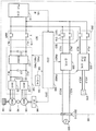
도 1은, 이 발명의 실시형태 1에 따른 차량의 전체 블록도이다.
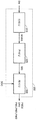
도 2는, 도 1에 나타내는 제어 장치의 급전 제어에 관한 기능 블록도이다.
도 3은, 도 1에 나타내는 제어 장치의 급전 제어에 관한 처리를 설명하기 위한 플로우 차트이다.
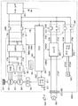
도 4는, 이 발명의 실시형태 2에 따른 차량의 전체 블록도이다.
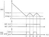
도 5는, 도 4에 나타내는 축전 장치의 SOC의 변화에 대한 엔진의 운전 상태를 나타내는 타임 차트이다.
도 6은, 도 4에 나타내는 제어 장치의 급전 제어에 관한 처리를 설명하기 위한 플로우 차트이다.
도 7은, 이 발명의 실시형태 3에 따른 축전 장치의 SOC의 변화에 대한 엔진의 운전 상태를 나타내는 타임 차트이다.
도 8은, 이 발명의 실시형태 3에 따른 제어 장치의 급전 제어에 관한 처리를 설명하기 위한 플로우 차트이다.
도 9는, 이 발명의 실시형태 4에 따른 제어 장치의 급전 제어에 관한 처리를 설명하기 위한 플로우 차트이다.
도 10은, 이 발명의 실시형태 4의 변형례에 따른 제어 장치의 급전 제어에 관한 처리를 설명하기 위한 플로우 차트이다.
도 11은, 이 발명의 실시형태 5에 따른 축전 장치의 SOC의 변화에 대한 엔진의 운전 상태를 나타내는 타임 차트이다.
도 12는, 이 발명의 실시형태 5에 따른 제어 장치의 급전 제어에 관한 처리를 설명하기 위한 플로우 차트이다.1 is an overall block diagram of a vehicle according to
Fig. 2 is a functional block diagram relating to power supply control of the control apparatus shown in Fig. 1. Fig.
3 is a flowchart for explaining a process related to power supply control of the control apparatus shown in Fig.
4 is an overall block diagram of a vehicle according to Embodiment 2 of the present invention.
5 is a time chart showing the operation state of the engine with respect to the change in the SOC of the power storage device shown in Fig.
Fig. 6 is a flowchart for explaining a process relating to power supply control of the control apparatus shown in Fig. 4;
Fig. 7 is a time chart showing the operating state of the engine with respect to the change of the SOC of the power storage device according to the third embodiment of the present invention. Fig.
Fig. 8 is a flowchart for explaining processing relating to power supply control of the control apparatus according to Embodiment 3 of the present invention. Fig.
Fig. 9 is a flowchart for explaining processing relating to power supply control of the control apparatus according to Embodiment 4 of the present invention. Fig.
Fig. 10 is a flowchart for explaining processing relating to power supply control of the control apparatus according to the modification of the fourth embodiment of the present invention. Fig.
11 is a time chart showing the operation state of the engine with respect to the change of the SOC of the power storage device according to Embodiment 5 of the present invention.
12 is a flowchart for explaining processing relating to power supply control of the control apparatus according to Embodiment 5 of the present invention.
이하, 본 발명의 실시형태에 대하여 도면을 참조하면서 상세하게 설명한다. 또한, 도면 중 동일한 또는 상당하는 부분에는 동일 부호를 붙여 그 설명은 반복하지 않는다.BEST MODE FOR CARRYING OUT THE INVENTION Hereinafter, embodiments of the present invention will be described in detail with reference to the drawings. In the drawings, the same or equivalent parts are denoted by the same reference numerals, and description thereof will not be repeated.
[실시형태 1][Embodiment 1]
도 1은, 이 발명의 실시형태 1에 따른 차량의 전체 블록도이다. 도 1을 참조하여, 차량(100)은 축전 장치(110)와, 시스템 메인 릴레이(System Main Relay:SMR)(115)와, 구동 장치인 PCU(Power Control Unit)(120)와, 모터 제너레이터(130, 135)와, 동력 전달 기어(140)와, 구동륜(150)과, 내연기관인 엔진(160)과, 제어 장치인 ECU(Electronic Control Unit)(300)를 구비한다. PCU(120)는 컨버터(121)와, 인버터(122, 123)와, 콘덴서(C1, C2)를 포함한다.1 is an overall block diagram of a vehicle according to
축전 장치(110)는, 충방전 가능하게 구성된 전력 저장 요소이다. 축전 장치(110)는 예를 들면, 리튬 이온 전지, 니켈 수소 전지 또는 연축 전지 등의 이차 전지, 혹은 전기 이중층 커패시터 등의 축전 소자를 포함하여 구성된다.The power storage device (110) is a power storage element configured to be chargeable and dischargeable. The
축전 장치(110)는 전력선(PL1, NL1)을 통해 PCU(120)에 접속된다. 그리고, 축전 장치(110)는 차량(100)의 구동력을 발생시키기 위한 전력을 PCU(120)에 공급한다. 또, 축전 장치(110)는 모터 제너레이터(130, 135)에서 발전된 전력을 축전한다. 축전 장치(110)의 출력은 예를 들면, 200V 정도이다.The
축전 장치(110)는, 모두 도시하지 않았으나 전압 센서 및 전류 센서를 포함하며, 이러한 센서에 의해 검출된, 축전 장치(110)의 전압(VB) 및 전류(IB)를 ECU(300)에 출력한다.The
SMR(115)은, 축전 장치(110)의 양극단(正極端) 및 PCU(120)에 접속되는 전력선(PL1)에 접속되는 릴레이와, 축전 장치(110)의 음극단 및 전력선(NL1)에 접속되는 릴레이를 포함한다. 그리고, SMR(115)은, ECU(300)로부터의 제어 신호(SE1)에 의거하여, 축전 장치(110)와 PCU(120) 사이에서의 전력의 공급과 차단을 전환한다.The
컨버터(121)는, ECU(300)로부터의 제어 신호(PWC)에 의거하여, 전력선(PL1, NL1)과 전력선(PL2, NL2)의 사이에서 전압 변환을 행한다.The
인버터(122, 123)는 전력선(PL2, NL2)에 병렬로 접속된다. 인버터(122, 123)는, ECU(300)로부터의 제어 신호(PWI1, PWI2)에 각각 의거하여, 컨버터(121)로부터 공급되는 직류 전력을 교류 전력으로 변환하고, 모터 제너레이터(130,135)를 각각 구동한다.
콘덴서(C1)는 전력선(PL1) 및 전력선(NL1)의 사이에 설치되고, 전력선(PL1) 및 전력선(NL1) 사이의 전압 변동을 감소시킨다. 또, 콘덴서(C2)는 전력선(PL2) 및 전력선(NL2)의 사이에 설치되고, 전력선(PL2) 및 전력선(NL2) 사이의 전압 변동을 감소시킨다.The capacitor C1 is provided between the power line PL1 and the power line NL1 and reduces the voltage fluctuation between the power line PL1 and the power line NL1. The capacitor C2 is provided between the power line PL2 and the power line NL2 and reduces the voltage fluctuation between the power line PL2 and the power line NL2.
모터 제너레이터(130,135)는 교류 회전 전기(電機)이며, 예를 들면, 영구 자석이 매설된 로터를 구비하는 영구 자석형 동기(同期) 전동기이다.The
모터 제너레이터(130,135)의 출력 토크는, 감속기나 동력 분할 장치를 포함하여 구성되는 동력 전달 기어(140)를 통해 구동륜(150)에 전달되어, 차량(100)을 주행시킨다. 모터 제너레이터(130,135)는, 차량(100)의 회생 제동 동작시에는 구동륜(150)의 회전력에 의해 발전할 수 있다. 그리고, 그 발전 전력은, PCU(120)에 의해 축전 장치(110)의 충전 전력으로 변환된다.The output torque of the
또한, 모터 제너레이터(130,135)는 동력 전달 기어(140)를 통해 엔진(160)과도 결합된다. 그리고, ECU(300)에 의해, 모터 제너레이터(130,135) 및 엔진(160)이 협조적으로 동작되어 필요한 차량 구동력이 발생된다. 또한, 모터 제너레이터(130,135)는 엔진(160)의 회전에 의해 발전이 가능하며, 이 발전 전력을 이용하여 축전 장치(110)를 충전할 수 있다. 또한, 본 실시형태에 있어서는, 모터 제너레이터(135)를 오로지 구동륜(150)을 구동하기 위한 전동기로서 이용하고, 모터 제너레이터(130)를 오로지 엔진(160)에 의해 구동되는 발전기로서 이용하는 것으로 한다.The
또한, 도 1에 있어서는, 모터 제너레이터가 2개 설치되는 구성이 예로서 나타내어져 있으나, 모터 제너레이터의 수는 이에 한정되지 않고, 모터 제너레이터가 1개인 경우, 또는 2개보다 많은 모터 제너레이터를 설치하는 구성으로 해도 된다.1 shows an example in which two motor generators are provided. However, the number of motor generators is not limited to this, and the number of motor generators may be one, or a configuration in which more than two motor generators are installed .
차량(100)은, 외부 전원(500)으로부터의 전력에 의해 축전 장치(110)를 충전하기 위한 구성으로서 충전기(200)와, 릴레이(210)와, 접속부인 인렛(220)을 포함한다.The
인렛(220)에는 외부 전원(500)의 커넥터(510)가 접속된다. 그리고, 외부 전원(500)으로부터의 전력이 차량(100)에 전달된다.The
충전기(200)는 전력선(ACL1, ACL2)을 통해 인렛(220)에 접속된다. 또, 충전기(200)는 릴레이(210)를 통해 전력선(PL3, NL3)에 의해 축전 장치(110)에 접속된다.The
충전기(200)는, ECU(300)로부터의 제어 신호(PWD1)에 의해 제어되고, 인렛(220)으로부터 공급되는 교류 전력을 축전 장치(110)의 충전 전력으로 변환한다.The
릴레이(210)는, ECU(300)로부터의 제어 신호(SE2)에 의해 제어되고, 충전기(200)와 축전 장치(110) 사이의 전력의 공급과 차단을 전환한다.The
차량(100)은, 축전 장치(110)로부터의 직류 전력, 또는 모터 제너레이터(130,135)에 의해 발전되어 PCU(120)에서 변환된 직류 전력을 교류 전력으로 변환하여 차량 외부에 급전하기 위한 구성으로서 전력 변환 장치(250)와, 릴레이(260)와, 콘센트(270)를 포함한다.The
릴레이(260)는, ECU(300)로부터의 제어 신호(SE3)에 의해 제어되고, 전력 변환 장치(250)와 축전 장치(110) 사이의 전력의 공급과 차단을 전환한다.The
전력 변환 장치(250)는 릴레이(260)를 통해 전력선(PL4, NL4)에 의해 축전 장치(110)에 접속된다. 또한, 전력 변환 장치(250)는 전력선(ACL3, ACL4)을 통해 콘센트(270)에 접속된다.
전력 변환 장치(250)는, ECU(300)로부터의 제어 신호(PWD2)에 의해 제어되고, 축전 장치(110) 또는 PCU(120)로부터 공급되는 직류 전력을 교류 전력으로 변환한다.The
콘센트(270)에는 차량 외부의 전기기기(도시 생략)가 접속된다. 그리고, 차량(100)으로부터의 전력이 외부의 전기기기에 전달된다.An electric appliance (not shown) outside the vehicle is connected to the
또한, 도 1에 있어서는, 충전기(200) 및 전력 변환 장치(250)를 설치하는 구성으로 하고 있으나, 쌍방향의 전력 변환이 가능한 1개의 전력 변환 장치가 충전기(200)의 기능과 전력 변환 장치(250)의 기능을 가지는 구성으로 해도 된다.1, a
ECU(300)는, 모두 도 1에는 도시하지 않았으나 CPU(Central Processing Unit), 기억 장치 및 입출력 버퍼를 포함하고, 각 센서 등으로부터의 신호의 입력이나 각 기기로의 제어 신호의 출력을 행함과 함께, 축전 장치(110) 및 차량(100)의 각 기기의 제어를 행한다. 또한, 이러한 제어에 대해서는, 소프트웨어에 의한 처리에 한정되지 않고, 전용의 하드웨어(전자 회로)로 처리하는 것도 가능하다.The
또한, 도 1에 있어서는, ECU(300)로서 1개의 제어 장치를 설치하는 구성으로 하고 있으나, 예를 들면, PCU(120)용의 제어 장치나 축전 장치(110)용의 제어 장치 등과 같이, 기능마다 또는 제어 대상 기기마다 개별의 제어 장치를 설치하는 구성으로 해도 된다.1, a single control device is provided as the
ECU(300)는, 축전 장치(110)로부터의 전압(VB) 및 전류(IB)의 검출값에 의거하여, 축전 장치(110)의 충전 상태(SOC:State of Charge)를 연산한다.
차량(100)은, CD(Charge Depleting) 모드 및 CS(Charge Sustaining) 모드의 주행 모드에 의해 주행이 가능하다. CD 모드는, 엔진(160)을 정지하여 모터 제너레이터(135)만을 이용한 주행을 우선시키는 모드이다. CS 모드는, 엔진(160)을 동작시켜 축전 장치(110)의 SOC를 소정의 목표로 유지하는 모드이다. ECU(300)는 SOC에 의거하여, 차량의 주행 모드의 전환을 제어한다.The
또한, CS 모드는, 축전 장치(110)의 SOC를 소정의 목표로 유지하기 위해, 필요에 따라 엔진(160)을 동작시켜 모터 제너레이터(130)에 의해 발전을 행하는 주행 모드이며, 엔진(160)을 상시 동작시킨 주행에 한정되는 것이 아니다. 한편, CD 모드에서도, 운전자에 의해 액셀 페달이 크게 밟히거나, 엔진 구동 타입의 에어컨 동작시나 엔진 난기시(暖機時) 등에는 엔진(160)의 동작이 허용된다. 이 CD 모드는, 축전 장치(110)의 SOC를 소정의 목표값으로 유지하지 않고, 기본적으로 축전 장치(110)에 저장된 전력을 에너지원으로 하여 차량을 주행시키는 주행 모드이다. 이 CD 모드 동안에는, 결과적으로 충전보다 방전의 비율 쪽이 상대적으로 커지는 경우가 많다.The CS mode is a running mode in which the
즉, 주행 모드가 CD 모드일지라도, 액셀 페달이 크게 밟혀 큰 차량 파워가 요구되면 엔진(160)은 동작한다. 또한, 주행 모드가 CS 모드일지라도, SOC가 목표값을 상회하고 있으면 엔진(160)은 정지한다. 그래서, 주행 모드에 관계없이, 엔진(160)을 정지하여 모터 제너레이터(135)만을 이용한 주행을 「EV주행」이라고 칭하고, 엔진(160)을 동작시켜 모터 제너레이터(135) 및 엔진(160)을 이용한 주행을 「HV주행」이라고 칭한다.That is, even if the driving mode is the CD mode, the
ECU(300)는, 조작 부재인 스위치(180)의 상태를 나타내는 신호(SW)를 스위치(180)로부터 받는다. 이용자는 스위치(180)을 조작함으로써 주행 모드를 선택할 수 있다. ECU(300)는 신호(SW)에 의거하여 이용자가 선택한 주행 모드를 취득한다. ECU(300)는 제어 신호(DRV)에 의해 엔진(160)을 제어한다.The
상술과 같은 차량에 있어서는, 스마트 그리드 등에 보여지는 바와 같이, 차량을 전력 공급원으로 생각하여, 차량 외부의 일반 전기기기에 대해 차량으로부터 전력을 공급하는 구상이 검토되어 있다. 또한, 캠프나 옥외에서의 작업 등에서 전기기기를 사용하는 경우의 전원으로서 차량이 사용되는 경우도 있다.[0003] In a vehicle such as the one described above, as shown in a smart grid or the like, a concept of supplying electric power from a vehicle to a general electric device outside the vehicle is considered as a vehicle as a power supply source. In addition, a vehicle may be used as a power source when an electric device is used in a camp or an outdoor work.
이와 같이 차량으로부터의 전력을 공급하는 경우에는, 일반적으로는, 축전 장치에 저장된 전력을 공급하는 것이 전제가 되어 있는 경우가 많다. 그리고, 축전 장치의 남은 용량이 저하되면, 엔진(160)의 구동력에 의해 발전된 전력을 공급하도록 전환된다. 그러나, 차량이 이너 개라지에 놓여 있는 경우, 또는, 차량으로부터의 급전이 심야에 행하여지는 경우 등에 있어서는, 엔진(160)의 운전에 따른 이미션이나 동작음 등의 관점에서 엔진의 운전이 바람직하지 않은 경우가 있다.In this way, when power is supplied from a vehicle, it is often the case that the power stored in the power storage device is supplied in many cases. When the remaining capacity of the power storage device is lowered, it is switched to supply the electric power generated by the driving force of the
그래서, 실시형태 1에 있어서는, 이용자가 선택한 주행 모드에 의거하여, 엔진(160)의 구동력에 의한 발전의 허가 및 금지가 설정되는 급전 제어를 실행한다.Thus, in the first embodiment, based on the traveling mode selected by the user, the power supply control in which permission and inhibition of power generation by the driving force of the
도 2는, 도 1에 나타내는 ECU(300)의 급전 제어에 관한 기능 블록도이다. 도 2를 참조하여, ECU(300)는 입력부(310)와, 판정부(320)와, 제어부(330)를 구비한다.2 is a functional block diagram related to power supply control of the
입력부(310)는 스위치(180)의 상태를 나타내는 신호(SW)를 스위치(180)로부터 받는다. 입력부(310)는 신호(SW)에 의거하여 이용자가 선택한 주행 모드를 취득한다. 입력부(310)는 이용자가 선택한 주행 모드(MODE)를 판정부(320)에 출력한다.The
판정부(320)는, 입력부(310)로부터 받은 주행 모드(MODE)에 의거하여, 엔진(160)의 구동력에 의한 발전을 허가하는지의 여부를 판정한다. 구체적으로는, 판정부(320)는, 주행 모드(MODE)가 CS 모드일 때에 엔진(160)의 구동력에 의한 발전을 허가한다. 판정부(320)는, 주행 모드(MODE)가 CD 모드일 때에 엔진(160)의 구동력에 의한 발전을 금지한다. 판정부(320)는, 엔진(160)의 구동력에 의한 발전을 허가하는지의 여부를 나타내는 신호(SIG)를 제어부(330)에 출력한다.The judging
제어부(330)는, 판정부(320)로부터 받은 신호(SIG)에 의거하여, 엔진(160), PCU(120), 전력 변환 장치(250)의 동작을 제어한다. 구체적으로는, 엔진(160)의 구동력에 의한 발전이 허가되어 있는 경우에는, 제어부(330)는 축전 장치(110)의 SOC가 저하되면 엔진(160)을 시동한다. 제어부(330)는, 엔진(160)의 구동력에 의해 모터 제너레이터(130)가 발전하도록 엔진(160) 및 PCU(120)를 제어한다. 제어부(330)는, 발전 전력을 콘센트(270)로부터 외부의 전기기기에 공급하도록 전력 변환 장치(250)를 제어한다. 한편, 엔진(160)의 구동력에 의한 발전이 금지되어 있는 경우에는, 제어부(330)는, 축전 장치(110)의 SOC가 저하되어도 엔진(160)을 시동하지 않고 외부의 전기기기로의 급전을 정지한다.The
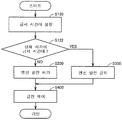
도 3은, 도 1에 나타내는 ECU(300)의 급전 제어에 관한 처리를 설명하기 위한 플로우 차트이다. 또한, 도 3, 도 6, 도 8∼도 10 및 도 12에 나타내어지는 플로우 차트 중의 각 단계에 대해서는, ECU(300)에 미리 저장된 프로그램이 메인 루틴으로부터 호출되어, 소정 주기 혹은 소정의 조건이 성립된 것에 응답하여 실행됨으로써 실현된다. 또는, 일부의 단계에 대해서는, 전용의 하드웨어(전자 회로)를 구축하여 처리를 실현하는 것도 가능하다.Fig. 3 is a flowchart for explaining processing relating to power supply control of the
도 3을 참조하여, ECU(300)는, 단계(이하, 단계를 S로 간략히 한다.) 100에서 스위치(180)로부터의 신호(SW)에 의거하여, 이용자가 선택한 주행 모드가 CS 모드인지의 여부를 판정한다. 이용자가 선택한 주행 모드가 CS 모드인 경우(S100에서 YES)에는, ECU(300)는 엔진(160)의 구동력에 의한 발전을 허가한다(S200).3, the
한편, 이용자가 선택한 주행 모드가 CS 모드가 아닌 경우(S100에서 NO)에는, ECU(300)는 엔진(160)의 구동력에 의한 발전을 금지한다(S300).On the other hand, when the user's selected running mode is not the CS mode (NO in S100), the
이어서 S400에 있어서, 엔진(160)의 구동력에 의한 발전이 허가되어 있는 경우에는, ECU(300)는, SOC에 따라 축전 장치(110)의 전력 및 엔진(160)에 의한 발전 전력을 외부의 전기기기에 공급한다. 한편, 엔진(160)의 구동력에 의한 발전이 금지되어 있는 경우에는, ECU(300)는, 축전 장치(110)의 전력만을 외부의 전기기기에 공급한다.When power generation by the driving force of the
이상과 같이, 이 실시형태 1에 의하면, 이용자는 차량(100)의 사용 양태에 따라 엔진(160) 운전의 가부를 결정할 수 있다.As described above, according to the first embodiment, the user can determine whether or not the
또한, 이 실시형태 1에 있어서는, 이용자는, 스위치(180)를 조작함으로써, 엔진(160)의 구동력에 의한 발전의 허가 및 금지를 선택할 수 있다. 따라서, 이용자는 차량의 주차 장소 등에 따라 간이한 조작으로 엔진(160)의 구동력에 의한 발전의 허가 및 금지를 선택할 수 있다.Further, in
또한, 이 실시형태 1에 있어서는, 차량(100)의 주행 모드를 선택하기 위한 스위치를 엔진(160)의 구동력에 의한 발전의 허가 및 금지를 선택하기 위한 스위치로서 이용할 수 있다. 따라서, 엔진(160)의 구동력에 의한 발전의 허가 및 금지를 선택하기 위한 스위치를 별도로 설치할 필요가 없어, 비용을 삭감할 수 있다.Further, in
또한, 이 실시형태 1에 있어서는, 주행 모드로서 CS 모드가 이용자에 의해 선택되어 있을 때에, 엔진(160)의 구동력에 의한 발전을 허가한다. 한편, 주행 모드로서 CD 모드가 이용자에 의해 선택되어 있을 때에, 엔진(160)의 구동력에 의한 발전을 금지한다. 따라서, 차량(100)의 주행 모드에 연동하여, 엔진(160)의 구동력에 의한 발전의 허가 및 금지를 설정할 수 있다. 따라서, 이용자의 편리성을 향상시킬 수 있다.Further, in the first embodiment, when the CS mode is selected as the running mode by the user, generation by the driving force of the
[실시형태 2][Embodiment 2]
실시형태 1에 있어서는, 이용자가 선택한 주행 모드에 의거하여, 엔진(160)의 구동력에 의한 발전의 허가 및 금지가 설정되는 경우를 설명하였다.In the first embodiment, the case where permission and inhibition of power generation by the driving force of the
실시형태 2에 있어서는, 이용자가 휴대하는 통신 단말의 조작에 의거하여, 엔진(160)의 구동력에 의한 발전의 허가 및 금지가 설정되는 경우를 설명한다.In the second embodiment, a case where permission and inhibition of power generation by the driving force of the
도 4는, 이 발명의 실시형태 2에 따른 차량의 전체 블록도이다. 도 4를 참조하여, 차량(100A)은, 실시형태 1의 구성에 추가로 통신 장치(170)를 더 구비한다.4 is an overall block diagram of a vehicle according to Embodiment 2 of the present invention. Referring to Fig. 4, the
통신 장치(170)는 ECU(300)에 접속된다. 통신 장치(170)는, 이용자가 휴대하는 통신 단말(900)과의 사이에서 통신을 행하도록 구성된다. 통신 장치(170)는, 안테나(175)를 통해 통신 단말(900)과의 사이에서 무선으로 데이터를 송수신한다. 통신 단말(900)은 예를 들면, 스마트폰 등의 휴대 단말이다.The
도 5는, 도 4에 나타내는 축전 장치(110)의 SOC의 변화에 대한 엔진(160)의 운전 상태를 나타내는 타임 차트이다.5 is a time chart showing the operating state of the
도 5을 참조하여, 시각 t1에 있어서, 차량(100A)이 외부의 전기기기에 전력을 공급함으로써 SOC가 문턱값 X를 하회하면, 통신 장치(170)는, ECU(300)로부터의 지령에 의거하여, 엔진(160)의 구동력에 의한 발전의 허가 및 금지의 선택을 요구하는 신호를 통신 단말(900)에 송신한다. 또한, 문턱값 X는 예를 들면, 축전 장치(110)의 하한 전압값이다. 또, 문턱값 X는 CD 모드 및 CS 모드를 전환하기 위한 값이어도 된다. 이용자는 요구를 수취하면, 통신 단말(900)을 조작함으로써 엔진(160)의 구동력에 의한 발전의 허가 및 금지를 결정한다.5, at time t1, when the SOC of the
통신 장치(170)는, 이용자가 결정한 엔진(160)의 구동력에 의한 발전의 허가 및 금지에 대한 정보를 통신 단말(900)로부터 수신하고, ECU(300)에 전송한다. ECU(300)는, 이용자가 엔진(160)의 구동력에 의한 발전을 허가하면, 엔진(160)을 시동하여 발전을 개시한다. 한편, ECU(300)는, 이용자가 엔진(160)의 구동력에 의한 발전을 허가하지 않는 경우에는, 축전 장치(110)의 SOC가 하한에 도달하면 엔진(160)을 시동하지 않고 외부의 전기기기로의 급전을 정지한다.The
시각 t2에 있어서, 발전에 의해 SOC가 목표값 A를 상회하면, ECU(300)는 엔진(160)의 운전을 정지한다.At time t2, when the SOC exceeds the target value A due to power generation, the
도 6은, 도 4에 나타내는 ECU(300)의 급전 제어에 관한 처리를 설명하기 위한 플로우 차트이다. 또한, S200∼S400에 대해서는, 실시형태 1과 동일하므로 설명을 반복하지 않는다.Fig. 6 is a flowchart for explaining processing relating to power supply control of the
도 6을 참조하여, S110에 있어서, ECU(300)는 축전 장치(110)의 SOC가 문턱값 X를 하회하였는지의 여부를 판정한다. 축전 장치(110)의 SOC가 문턱값 X를 하회한 경우(S110에서 YES)에는, ECU(300)는, 엔진(160)의 구동력에 의한 발전의 허가 및 금지의 선택을 요구하는 신호를 통신 단말(900)에 송신하도록 통신 장치(170)를 제어한다(S112).Referring to Fig. 6, at S110, the
이어서 S114에 있어서, ECU(300)는, 통신 장치(170)가 수신한 신호에 의거하여, 이용자가 엔진(160)의 구동력에 의한 발전을 허가하였는지의 여부를 판정한다. 이용자가 엔진(160)의 구동력에 의한 발전을 허가한 경우(S114에서 YES)에는 처리가 S200으로 진행된다. 한편, 이용자가 엔진(160)의 구동력에 의한 발전을 허가하지 않는 경우(S114에서 NO)에는 처리가 S300으로 진행된다.Subsequently, in S114, the
축전 장치(110)의 SOC가 문턱값 X를 하회하지 않는 경우(S110에서 NO)에는 처리가 S300으로 진행된다.If the SOC of the
이상과 같이, 이 실시형태 2에 있어서는, 이용자가 휴대하는 통신 단말(900)의 조작에 의거하여, 엔진(160)의 구동력에 의한 발전의 허가 및 금지가 설정된다. 따라서, 이용자는, 차량(100A)으로부터 떨어진 장소에 있는 경우일지라도, 엔진(160)의 운전 및 정지를 선택할 수 있다.As described above, in the second embodiment, permission and inhibition of power generation by the driving force of the
또한, 이 실시형태 2에 있어서는, SOC가 문턱값 X를 하회했을 때에, 이용자는 엔진(160)의 구동력에 의한 발전의 허가 및 금지의 선택이 요구된다. 따라서, 엔진(160)이 시동하기 전에, 이용자는 엔진(160)의 운전 및 정지를 선택할 수 있다.Further, in the second embodiment, when the SOC falls below the threshold X, the user is required to select the permission or inhibition of the power generation by the driving force of the
또한, 이 실시형태 2에 있어서는, 통신 장치(170)에 의하지 않고, 차량(100A)에 설치된 버저 또는 라이트 등을 이용하여 상기 요구를 이용자에게 통지하도록 구성되어도 된다. 이 경우, 이용자는, 차량(100A)에 설치된 버튼 또는 네비게이션 시스템의 조작 화면 등을 이용하여 엔진(160)의 운전 및 정지를 선택한다.In the second embodiment, the request may be notified to the user by using a buzzer or a light installed in the
또한, 이 실시형태 2에 있어서는, 통신 장치(170)는, 통신 단말(900) 대신에, 차량(100A)으로부터의 전력을 수전하는 수전 장치와의 사이에서 통신하도록 구성되어도 된다. 이 경우, 이용자는 수전 장치를 조작함으로써, 엔진(160)의 구동력에 의한 발전의 허가 및 금지를 선택할 수 있다. 수전 장치는 예를 들면, HEMS(Home Energy Management System)를 구성하기 위한 것이다. 또한, 통신 장치(170)와 수전 장치 사이의 통신은 무선통신에 한정되지 않고, 유선통신이어도 된다.In the second embodiment, the
[실시형태 3][Embodiment 3]
실시형태 2에 있어서는, 차량이 구비하는 통신 장치로부터의 요구가 있을 때마다, 이용자가 휴대하는 통신 단말을 조작할 필요가 있었다. 또, 통신 장치로부터의 요구가 있는 경우에, 이용자가 바로 통신 단말을 조작할 수 없는 경우가 있다.In the second embodiment, whenever there is a request from the communication device provided in the vehicle, it is necessary to operate the communication terminal carried by the user. In addition, when there is a request from the communication device, the user may not be able to directly operate the communication terminal.
실시형태 3에 있어서는, 엔진의 구동력에 의한 발전이 금지되는 금지 시간대를 이용자가 미리 설정 가능하게 하여, 이용자에 의한 매회의 조작을 억제하는 구성을 설명한다.In the third embodiment, a configuration is described in which the user can set a prohibition time period during which power generation by the driving force of the engine is inhibited, and the operation by the user is inhibited each time.
도 7은, 이 발명의 실시형태 3에 따른 축전 장치(110)의 SOC의 변화에 대한 엔진의 운전 상태를 나타내는 타임 차트이다.7 is a time chart showing the operation state of the engine with respect to the change in the SOC of the
도 7을 참조하여, 이용자는 시각 t10∼t11 사이의 시간대 및 시각 t12∼t13 사이의 시간대를 금지 시간대로 하여 ECU(300)에 미리 설정한다. 또한, 금지 시간대의 설정은, 예를 들면, 이용자가 휴대하는 통신 단말이나 네비게이션 시스템의 조작 화면 등을 이용하여 행하여진다.Referring to Fig. 7, the user sets in advance the time zone between the time t10 and t11 and the time zone between the time t12 and t13 in the
시각 t10에 있어서, ECU(300)는, 축전 장치(110)의 전력에 의해 외부의 전기기기로의 급전을 개시한다. 시각 t11에 있어서, 시각이 금지 시간대가 아니게 되면, ECU(300)는 엔진(160)을 시동하여 발전을 개시한다.At time t10, the
시각 t12에 있어서, 시각이 금지 시간대가 되면, ECU(300)는 엔진(160)의 운전을 정지한다. 또한, ECU(300)는 금지 시간대가 설정되어 있는 경우에, SOC의 목표값을 목표값 B로 설정한다. 한편, ECU(300)는 금지 시간대가 설정되어 있지 않은 경우에, SOC의 목표값을 목표값 C로 설정한다. 목표값 B는 목표값 C보다 큰 값이다. 이와 같이, 금지 시간대가 설정되어 있는 경우의 목표 SOC를 높게 설정함으로써, 금지 시간대에 있어서의 축전 장치(110)의 방전 가능 전력량을 확보할 수 있다.At time t12, when the time becomes the prohibition time zone, the
도 8은, 이 발명의 실시형태 3에 따른 ECU(300)의 급전 제어에 관한 처리를 설명하기 위한 플로우 차트이다. 또한, S200∼S400에 대해서는, 실시형태 1과 동일하므로 설명을 반복하지 않는다.Fig. 8 is a flowchart for explaining a process relating to power supply control of the
도 8을 참조하여, S120에 있어서, ECU(300)는 이용자로부터의 입력에 의거하여, 금지 시간대를 설정한다.Referring to Fig. 8, in S120, the
이어서 S122에 있어서, ECU(300)는 현재 시각이 금지 시간대에 포함되는지의 여부를 판정한다. 현재 시각이 금지 시간대에 포함되지 않는 경우(S122에서 NO)에는 처리가 S200으로 진행된다. 한편, 현재 시각이 금지 시간대에 포함되는 경우(S122에서 YES)에는 처리가 S300으로 진행된다.Subsequently, in S122, the
이상과 같이, 이 실시형태 3에 있어서는, 금지 시간대를 이용자가 미리 설정할 수 있다. 따라서, 이용자가 설정한 금지 시간대에 따라 자동적으로 엔진(160)의 운전 및 정지를 전환할 수 있다.As described above, in the third embodiment, the prohibited time zone can be preset by the user. Therefore, the operation and stop of the
또한, 이 실시형태 3에 있어서는, 금지 시간대가 설정되어 있는 경우의 목표값 B가, 금지 시간대가 설정되어 있지 않은 경우의 목표값 C보다 높게 설정된다. 따라서, 금지 시간대에 있어서의 축전 장치(110)의 전력에 의한 급전량을 확보할 수 있다.In the third embodiment, the target value B when the prohibited time zone is set is set to be higher than the target value C when the prohibited time zone is not set. Therefore, it is possible to secure the amount of power supply by the
또한, 이 실시형태 3에 있어서는, 축전 장치(110)의 SOC가 문턱값 Y를 하회한 것에 응답하여, 엔진(160)의 구동력에 의한 발전을 개시하고, 금지 시간대가 설정되어 있는 경우의 문턱값 Y1을, 금지 시간대가 설정되어 있지 않은 경우의 문턱값 Y2보다 높게 하는 구성을 채용해도 된다. 이 경우도, 금지 시간대에 있어서의 축전 장치(110)의 전력에 의한 급전량을 확보할 수 있다.In the third embodiment, in response to the SOC of the
실시형태 3에 있어서는, SOC를 확보하는 구체적인 방법으로서 이하와 같은 변형례를 채용하는 것도 가능하다. 예를 들면, 실시형태 3의 변형례 1에 있어서는, 금지 시간대가 설정되어 있는 경우에는, 금지 시간대의 개시 전에 엔진(160)의 구동력에 의한 발전이 행하여진다. 이 경우도, 금지 시간대에 있어서의 축전 장치(110)의 전력에 의한 급전량을 확보할 수 있다.In the third embodiment, the following modifications may be employed as specific methods for ensuring SOC. For example, in the first modified example of the third embodiment, when the prohibited time zone is set, power generation by the driving force of the
또한, 실시형태 3의 변형례 2에 있어서는, 금지 시간대가 설정되어 있는 경우의 발전 전력을, 금지 시간대가 설정되어 있지 않은 경우의 발전 전력보다 크게 하도록 구성된다. 이 경우, 발전에 의해 SOC가 빠르게 상승함으로써, 금지 시간대가 아닌 기간이 짧은 경우일지라도, 금지 시간대에 있어서의 축전 장치(110)의 전력에 의한 급전량을 확보할 수 있다.In the second modification of the third embodiment, the generated power when the prohibited time period is set is made larger than the generated power when the prohibited time period is not set. In this case, since the SOC rapidly rises due to power generation, even if the period other than the prohibition time period is short, the power supply amount of the
또한, 실시형태 3의 변형례 3에 있어서는, 금지 시간대 대신에, 축전 장치(110)의 SOC의 목표값을 높게 하는 시간대를 이용자가 미리 설정할 수 있도록 구성된다. 이 경우, 이용자는, 엔진(160)의 운전이 허용되는 시간대에, 엔진(160)의 구동력에 의한 발전을 행하여 SOC를 높여둘 수 있다.In the third modification of the third embodiment, the user can set a time zone in which the target value of the SOC of the
또한, 실시형태 3의 변형례 4에 있어서는, 축전 장치(110)의 SOC가 소정값을 하회한 것에 응답하여, 엔진(160)의 구동력에 의한 발전을 개시하고, 금지 시간대 대신에, 상기 소정값을 높게 하는 시간대를 이용자가 미리 설정할 수 있도록 구성된다. 이 경우도, 이용자는, 엔진(160)의 운전이 허용되는 시간대에 엔진(160)의 구동력에 의한 발전을 행하여 SOC를 높여둘 수 있다.In the fourth modification of the third embodiment, power generation by the driving force of the
또한, 실시형태 3의 변형례 5에 있어서는, 금지 시간대 대신에, 축전 장치(110)의 SOC에 관계없이 엔진(160)의 구동력에 의한 발전이 행하여지는 시간대를 이용자가 미리 설정할 수 있도록 구성된다. 이 경우도, 이용자는, 엔진(160)의 운전이 허용되는 시간대에 엔진(160)의 구동력에 의한 발전을 행하여 SOC를 높여둘 수 있다.In the fifth modification of the third embodiment, instead of the prohibition time period, the user can set the time period during which power generation by the driving force of the
[실시형태 4][Embodiment 4]
실시형태 4에 있어서는, 이용자에 의한 선택과, 미리 설정된 판정 조건에 의한 판정 결과에 의거하여, 엔진의 구동력에 의한 발전의 허가 및 금지를 설정하는 구성을 설명한다.In Embodiment 4, a configuration for setting permission and inhibition of power generation by the driving force of the engine will be described on the basis of the selection by the user and the determination result based on the preset determination condition.
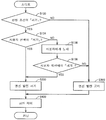
도 9는, 이 발명의 실시형태 4에 따른 ECU(300)의 급전 제어에 관한 처리를 설명하기 위한 플로우 차트이다. 또한, S200∼S400에 대해서는 실시형태 1과 동일하므로 설명을 반복하지 않는다.Fig. 9 is a flowchart for explaining a process related to power supply control of the
도 9를 참조하여, S130에 있어서, ECU(300)는 미리 설정된 판정 조건에 의거하여 엔진 발전을 허가하는지의 여부를 판정한다. 미리 설정된 판정 조건은 차량이 검지하는 정보에 의거한 판정 조건으로서, 이용자에 의한 설정이 가능한 판정 조건과, 이용자에 의한 설정이 불가능한 판정 조건을 포함한다. 이용자에 의한 설정이 가능한 판정 조건은 예를 들면, 전기 요금에 관한 정보에 의거한 판정 조건이다. 이용자에 의한 설정이 불가능한 판정 조건은 차량의 상태, 차량이 주행하는 지역 및 차량이 놓여진 환경 중 적어도 1개를 포함한다. 차량의 상태는 예를 들면, 엔진 수온이 상한값을 상회하는 것이다. 차량이 주행하는 지역은 예를 들면, GPS 등의 내비게이션 정보에 의해 얻어진 차량의 위치가 소정의 범위 내에 있는 것이다. 차량이 놓여진 환경은 예를 들면, 차량이 옥내의 개라지에 놓여져 있어 배기 가스 배출 설비가 없는 것, 또는, 가연물이 주위에 존재하는 것 등이다.Referring to Fig. 9, at S130, the
엔진 발전을 허가하는 경우(S130에서 YES)에는 처리가 S132로 진행된다. 한편, 엔진 발전을 허가하지 않는 경우(S130에서 NO)에는 처리가 S300으로 진행된다.When the engine power generation is permitted (YES in S130), the process proceeds to S132. On the other hand, if engine power generation is not permitted (NO in S130), the process proceeds to S300.
S132에 있어서, ECU(300)는, 이용자에 의한 선택이 엔진 발전을 허가하는지의 여부를 판정한다. 또한, 이용자에 의한 선택은 예를 들면, 스위치(180)나 통신 단말(900)을 이용하여 행하여진다. 이용자에 의한 선택이 엔진 발전을 허가하는 경우(S132에서 YES), 처리가 S200으로 진행된다. 한편, 이용자에 의한 선택이 엔진 발전을 허가하지 않는 경우(S132에서 NO), 처리가 S300으로 진행된다.In S132, the
이상과 같이, 이 실시형태 4에 있어서는, ECU(300)는, 이용자에 의한 선택과 미리 설정된 판정 조건에 의한 판정 결과가 다른 경우에는, 판정 결과를 우선하여 엔진의 구동력에 의한 발전의 허가 및 금지를 설정한다. 따라서, 이용자가 오조작을 행한 경우라도 안전성을 담보할 수 있다.As described above, in the fourth embodiment, in the case where the selection by the user and the determination result based on the predetermined determination condition are different, the
[변형례][Modifications]
실시형태 4의 변형례에 있어서는, 실시형태 4와 동일하게, 이용자에 의한 선택과 미리 설정된 판정 조건에 의한 판정 결과에 의거하여, 엔진의 구동력에 의한 발전의 허가 및 금지를 설정한다. 또한, 실시형태 4의 변형례에 있어서는, 이용자에 의한 선택과 미리 설정된 판정 조건에 의한 판정 결과가 다른 경우에는, 이용자에 의한 선택의 확인을 촉구하는 정보를 이용자에게 통지한다.In the modification of the fourth embodiment, similarly to the fourth embodiment, permission and inhibition of power generation by the driving force of the engine is set based on the selection by the user and the determination result based on the predetermined determination condition. In the modification of the fourth embodiment, when the selection by the user and the determination result based on the predetermined determination condition are different, the user is notified of information urging confirmation of the selection by the user.
도 10은, 이 발명의 실시형태 4의 변형례에 따른 ECU(300)의 급전 제어에 관한 처리를 설명하기 위한 플로우 차트이다. 또한, S130, S200∼S400에 대해서는, 실시형태 4와 동일하므로 설명을 반복하지 않는다.Fig. 10 is a flowchart for explaining processing relating to power supply control of the
도 10을 참조하여, S134에 있어서, ECU(300)는 이용자에 의한 선택이 엔진 발전을 허가하는지의 여부를 판정한다. 또한, 이용자에 의한 선택은 예를 들면, 스위치(180)나 통신 단말(900)을 이용하여 행하여진다. 이용자에 의한 선택이 엔진 발전을 허가하는 경우(S134에서 YES)에는 처리가 S200으로 진행된다. 한편, 이용자에 의한 선택이 엔진 발전을 허가하지 않는 경우(S134에서 NO)에는 처리가 S136으로 진행된다.Referring to Fig. 10, in S134, the
S136에 있어서, ECU(300)는, 이용자에 의한 선택과 미리 설정된 판정 조건에 의한 판정 결과가 다른 것을 이용자에게 통지한다.In S136, the
이어서 S138에 있어서, ECU(300)는, 이용자에 의한 재선택을 수취하면, 이용자에 의한 재선택이 엔진 발전을 허가하는지의 여부를 판정한다. 이용자에 의한 재선택이 엔진 발전을 허가하는 경우(S138에서 YES)에는 처리가 S200으로 진행된다. 한편, 이용자에 의한 재선택이 엔진 발전을 허가하지 않는 경우(S138에서 NO)에는 처리가 S300으로 진행된다.Subsequently, in S138, upon receipt of the reselection by the user, the
이상과 같이, 이 실시형태 4의 변형례에 있어서는, ECU(300)는, 이용자에 의한 선택과 미리 설정된 판정 조건에 의한 판정 결과가 다른 경우에는, 이용자에 의한 선택의 확인을 촉구하는 정보를 이용자에게 통지한다. 따라서, 실시형태 4와 마찬가지로, 이용자가 오조작을 행한 경우라도 안전성을 담보할 수 있다.As described above, in the modification of the fourth embodiment, when the selection by the user and the determination result based on the preset determination condition are different, the
[실시형태 5][Embodiment 5]
실시형태 5에 있어서는, 엔진의 시동을 개시하는 SOC를 이용자가 설정 가능한 구성을 설명한다.In Embodiment 5, a configuration in which the user can set the SOC for starting the engine will be described.
도 11은, 이 발명의 실시형태 5에 따른 축전 장치(110)의 SOC의 변화에 대한 엔진의 운전 상태를 나타내는 타임 차트이다.11 is a time chart showing the operation state of the engine with respect to a change in SOC of
도 11을 참조하여, 이용자는, 엔진(160)의 구동력에 의한 발전을 개시하기 위한 문턱값 Z를 ECU(300)에 미리 설정한다. 또한, 문턱값 Z의 설정은, 예를 들면, 이용자가 휴대하는 통신 단말이나 네비게이션 시스템의 조작 화면 등을 이용하여 행하여진다. 시각 t20에 있어서, 차량(100)이 외부의 전기기기에 전력을 공급함으로써 SOC가 문턱값 Z를 하회하면, ECU(300)는 엔진(160)을 시동하여 발전을 개시한다.11, the user sets in advance the threshold value Z for starting power generation by the driving force of the
시각 t21에 있어서, 발전에 의해 SOC가 목표값 D를 상회하면, ECU(300)는 엔진(160)의 운전을 정지한다.At time t21, when the SOC exceeds the target value D due to power generation, the
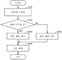
도 12는, 이 발명의 실시형태 5에 따른 ECU(300)의 급전 제어에 관한 처리를 설명하기 위한 플로우 차트이다. 또한, S200∼S400에 대해서는, 실시형태 1과 동일하므로 설명을 반복하지 않는다.Fig. 12 is a flowchart for explaining processing relating to power supply control of the
도 12를 참조하여, S140에 있어서, ECU(300)는 이용자로부터의 입력에 의거하여 문턱값 Z를 설정한다.Referring to Fig. 12, in S140, the
이어서 S142에 있어서, ECU(300)는, SOC가 문턱값 Z를 하회하였는지의 여부를 판정한다. SOC가 문턱값 Z를 하회한 경우(S142에서 YES)에는 처리가 S200으로 진행된다. 한편, SOC가 문턱값 Z를 하회하지 않는 경우(S142에서 NO)에는 처리가 S300으로 진행된다.Subsequently, in S142, the
이상과 같이, 이 실시형태 5에 있어서는, 이용자는 엔진의 시동을 개시하는 SOC를 설정할 수 있다. 따라서, 이용자는 엔진의 시동을 개시하는 SOC를 높게 설정함으로써, 외부의 전기기기에 급전하는 경우에 있어서, SOC를 높게 유지할 수 있다. 따라서, 외부의 전기기기로의 급전을 종료한 후일지라도, EV주행을 행하기 위한 전력량을 확보할 수 있다.As described above, in the fifth embodiment, the user can set the SOC for starting the engine. Accordingly, the user can maintain the SOC at a high level when power is supplied to the external electric device by setting the SOC for starting the engine to be high. Therefore, even after the power supply to the external electric device is completed, the amount of electric power for EV traveling can be ensured.
또한, 상기에 있어서, 모터 제너레이터(130,135)는 이 발명에 있어서의 「전동기」의 일실시예에 대응하고, 스위치(180)는 이 발명에 있어서의 「조작부」의 일실시예에 대응한다. 또한, CD 모드는 이 발명에 있어서의 「제 1 주행 모드」의 일실시예에 대응하고, CS 모드는 이 발명에 있어서의 「제 2 주행 모드」의 일실시예에 대응한다.In the above, the
이번에 개시된 실시형태는 모든 점에서 예시이며 제한적인 것이 아니라고 생각되어야 한다. 본 발명의 범위는 상기한 실시형태의 설명이 아니라 청구범위에 의해 나타내어지며, 청구범위와 균등한 의미 및 범위 내에서의 모든 변경이 포함되는 것이 의도된다.The embodiments disclosed herein are to be considered in all respects as illustrative and not restrictive. The scope of the present invention is not limited to the above description of the embodiments but is defined by the claims, and is intended to include all modifications within the meaning and scope equivalent to the claims.
100, 100A : 차량
110 : 축전 장치
120 : PCU
121 : 컨버터
122, 123 : 인버터
130, 135 : 모터 제너레이터
140 : 동력 전달 기어
150 : 구동륜
160 : 엔진
170 : 통신 장치
175 : 안테나
180 : 스위치
200 : 충전기
210, 260 : 릴레이
220 : 인렛
250 : 전력 변환 장치
270 : 콘센트
500 : 외부 전원
510 : 커넥터
900 : 통신 단말100, 100A: vehicle
110: Power storage device
120: PCU
121: Converter
122, 123: Inverter
130, 135: motor generator
140: Power transmission gear
150:
160: engine
170: communication device
175: Antenna
180: Switch
200: Charger
210, 260: Relay
220: Inlet
250: power converter
270: Outlet
500: External power source
510: Connector
900: communication terminal
Claims (22)
상기 엔진의 구동력에 의해 발전을 행하는 전동기(130, 135)와,
축전 장치(110)와,
상기 전동기로부터의 발전 전력 및 상기 축전 장치에 저장된 전력 중 적어도 일방의 전력의 차량 외부로의 공급을 제어하기 위한 제어 장치(300)를 구비하고,
상기 제어 장치는, 이용자에 의한 설정에 의거하여, 상기 엔진의 구동력에 의한 발전의 허가 및 금지를 선택 가능하게 구성되는 차량.An engine 160,
Electric motors (130, 135) for generating electric power by the driving force of the engine,
A power storage device 110,
(300) for controlling supply of at least one of electric power generated from the electric motor and electric power stored in the power storage device to the outside of the vehicle,
Wherein the control device is configured to be capable of selecting permission and prohibition of power generation by the driving force of the engine based on a setting by a user.
상기 엔진의 구동력에 의한 발전의 허가 및 금지를 선택하기 위하여, 이용자에 의해 조작되는 조작부(180)를 더 구비하고,
상기 제어 장치는, 상기 조작부의 상태에 의거하여, 상기 엔진의 구동력에 의한 발전의 허가 및 금지를 설정하는 차량.The method according to claim 1,
Further comprising an operation unit (180) operated by a user to select permission or prohibition of generation of power by the driving force of the engine,
And the control device sets permits and prohibitions of power generation by the driving force of the engine based on the state of the operating portion.
상기 조작부는, 상기 차량의 주행 모드를 선택하기 위한 스위치인 차량.3. The method of claim 2,
Wherein the operation unit is a switch for selecting a running mode of the vehicle.
상기 차량은, 상기 엔진을 정지하여 상기 전동기만을 이용한 주행을 우선시키는 제 1 주행 모드와, 상기 엔진을 동작시켜 상기 축전 장치의 충전 상태를 나타내는 상태량을 소정의 목표로 유지하는 제 2 주행 모드를 포함하는 주행 모드를 전환하여 주행 가능하고,
상기 조작부는, 상기 제 1 주행 모드 및 상기 제 2 주행 모드를 선택하기 위한 스위치이며,
상기 제어 장치는, 외부로의 전력 공급시에 상기 제 2 주행 모드가 선택되어 있을 때는, 상기 엔진의 구동력에 의한 발전을 허가하는 차량.3. The method of claim 2,
The vehicle includes a first running mode in which the engine is stopped to give priority to running using only the electric motor and a second running mode in which the engine is operated to maintain a state amount indicating a state of charge of the power storage device at a predetermined target It is possible to change the running mode to run,
Wherein the operating unit is a switch for selecting the first traveling mode and the second traveling mode,
Wherein the control device permits power generation by the driving force of the engine when the second traveling mode is selected when power is supplied to the outside.
상기 제어 장치는, 외부로의 전력 공급시에 상기 제 1 주행 모드가 선택되어 있을 때는, 상기 엔진의 구동력에 의한 발전을 금지하는 차량.5. The method of claim 4,
Wherein the control device inhibits generation of power by the driving force of the engine when the first traveling mode is selected when power is supplied to the outside.
이용자가 휴대하는 통신 단말과의 사이에서 통신하도록 구성된 통신 장치(170)를 더 구비하고,
상기 통신 장치는, 상기 엔진의 구동력에 의한 발전의 허가 및 금지의 선택을 요구하는 신호를 상기 통신 단말에 송신하고, 이용자가 결정한 상기 엔진의 구동력에 의한 발전의 허가 및 금지에 대한 정보를 상기 통신 단말로부터 수신하며,
상기 제어 장치는, 상기 정보에 의거하여, 상기 엔진의 구동력에 의한 발전의 허가 및 금지를 설정하는 차량.The method according to claim 1,
Further comprising a communication device (170) configured to communicate with a communication terminal carried by the user,
The communication device transmits to the communication terminal a signal requesting selection of permission and prohibition of power generation by the driving force of the engine and transmits information about permission and prohibition of power generation by the driving force of the engine determined by the user to the communication Receiving from the terminal,
Wherein the control device sets permission and prohibition of generation by the driving force of the engine based on the information.
상기 통신 장치는, 상기 축전 장치의 충전 상태가 문턱값을 하회했을 때에, 상기 요구를 상기 통신 단말에 송신하는 차량.The method according to claim 6,
And the communication device transmits the request to the communication terminal when the state of charge of the power storage device is lower than a threshold value.
상기 차량으로부터의 전력을 수전하는 수전 장치와의 사이에서 통신하도록 구성된 통신 장치를 더 구비하고,
상기 통신 장치는, 상기 엔진의 구동력에 의한 발전의 허가 및 금지의 선택을 요구하는 신호를 상기 수전 장치에 송신하고, 이용자가 결정한 상기 엔진의 구동력에 의한 발전의 허가 및 금지에 대한 정보를 상기 수전 장치로부터 수신하며,
상기 제어 장치는, 상기 정보에 의거하여, 상기 엔진의 구동력에 의한 발전의 허가 및 금지를 설정하는 차량.The method according to claim 1,
Further comprising a communication device configured to communicate with a power reception device for receiving electric power from the vehicle,
The communication device transmits a signal requesting selection of permission and prohibition of generation of power by the driving force of the engine to the power receiving device and transmits information about permission and prohibition of power generation by the driving force of the engine determined by the user to the power receiving device Device,
Wherein the control device sets permission and prohibition of generation by the driving force of the engine based on the information.
상기 통신 장치는, 상기 축전 장치의 충전 상태가 문턱값을 하회했을 때에, 상기 요구를 상기 수전 장치에 송신하는 차량.9. The method of claim 8,
And the communication device transmits the request to the power reception device when the state of charge of the power storage device is lower than a threshold value.
상기 제어 장치는, 상기 축전 장치의 충전 상태를 나타내는 상태량의 목표값이 되도록 상기 축전 장치의 충전 상태를 제어하고, 상기 목표값을 높게 하는 시간대를 이용자가 미리 설정 가능하게 구성되는 차량.The method according to claim 1,
Wherein the control device controls the charging state of the power storage device so as to become the target value of the state quantity indicating the state of charge of the power storage device and allows the user to set a time zone for raising the target value in advance.
상기 제어 장치는, 상기 축전 장치의 충전 상태가 소정값을 하회한 것에 응답하여, 상기 엔진의 구동력에 의한 발전을 개시하고, 상기 소정값을 높게 하는 시간대를 이용자가 미리 설정 가능하게 구성되는 차량.The method according to claim 1,
Wherein the control device is configured to allow the user to set a time zone in which the power generation by the driving force of the engine is started and the predetermined value is raised in response to the charge state of the power storage device being lower than a predetermined value.
상기 제어 장치는, 상기 축전 장치의 충전 상태에 관계없이, 상기 엔진의 구동력에 의한 발전이 행하여지는 시간대를 이용자가 미리 설정 가능하게 구성되는 차량.The method according to claim 1,
Wherein the control device is configured such that the user can set a time period during which power generation by the driving force of the engine is performed irrespective of the charging state of the power storage device.
상기 제어 장치는, 상기 엔진의 구동력에 의한 발전이 금지되는 시간대를 이용자가 미리 설정 가능하게 구성되는 차량.The method according to claim 1,
Wherein the control device is configured such that a user can set a time zone during which power generation by the driving force of the engine is prohibited.
상기 제어 장치는, 상기 축전 장치의 충전 상태를 나타내는 상태량의 목표값이 되도록 상기 축전 장치의 충전 상태를 제어하고, 상기 시간대가 설정되어 있는 경우에는, 상기 시간대가 설정되어 있지 않은 경우에 비해, 상기 시간대의 개시 전에 상기 목표값을 높게 하는 차량.14. The method of claim 13,
The control device controls the charging state of the power storage device so as to become the target value of the state quantity indicating the state of charge of the power storage device, and when the time slot is set, And increases the target value before the start of the time zone.
상기 제어 장치는, 상기 축전 장치의 충전 상태가 문턱값을 하회한 것에 응답하여, 상기 엔진의 구동력에 의한 발전을 개시하고, 상기 시간대가 설정되어 있는 경우의 문턱값을, 상기 시간대가 설정되어 있지 않은 경우의 문턱값보다 높게 하는 차량.14. The method of claim 13,
Wherein the control device starts power generation by the driving force of the engine in response to the charging state of the power storage device being lower than a threshold value and sets a threshold value when the time period is set to a value Is higher than a threshold value in the case where the vehicle is not running.
상기 제어 장치는, 상기 시간대가 설정되어 있는 경우에는, 상기 시간대의 개시 전에 상기 엔진의 구동력에 의한 발전을 행하는 차량.14. The method of claim 13,
Wherein the control device performs power generation by the driving force of the engine before the start of the time zone when the time zone is set.
상기 제어 장치는, 미리 설정된 판정 조건에 의거하여 상기 엔진의 구동력에 의한 발전의 허가 및 금지를 판정하고, 이용자에 의한 선택과 상기 판정에 의한 결과가 다른 경우에는, 상기 판정에 의한 결과를 우선하여 상기 엔진의 구동력에 의한 발전의 허가 및 금지를 설정하는 차량.The method according to claim 1,
The control device determines permission / prohibition of power generation by the drive force of the engine based on preset determination conditions, and when the result of selection by the user is different from the result of the determination, the control device gives priority to the result of the determination And setting permission and prohibition of power generation by the driving force of the engine.
상기 제어 장치는, 미리 설정된 판정 조건에 의거하여 상기 엔진의 구동력에 의한 발전의 허가 및 금지를 판정하고, 이용자에 의한 선택과 상기 판정에 의한 결과가 다른 경우에는, 이용자에 의한 선택의 확인을 촉구하는 정보를 이용자에게 통지하는 차량.The method according to claim 1,
The control device determines permission / prohibition of power generation by the driving force of the engine on the basis of preset determination conditions, and prompts confirmation of the selection by the user when the selection by the user and the result by the determination are different To the user.
상기 판정 조건은, 이용자에 의한 설정이 가능한 판정 조건과, 이용자에 의한 설정이 불가능한 판정 조건을 포함하는 차량.The method according to claim 17 or 18,
Wherein the determination condition includes a determination condition that can be set by a user and a determination condition that can not be set by a user.
상기 이용자에 의한 설정이 불가능한 판정 조건은, 상기 차량의 상태, 상기 차량이 주행하는 지역 및 상기 차량이 놓여지는 환경 중 적어도 1개를 포함하는 차량.20. The method of claim 19,
Wherein the determination condition that can not be set by the user includes at least one of a state of the vehicle, an area in which the vehicle travels, and an environment in which the vehicle is placed.
상기 제어 장치는, 상기 축전 장치의 충전 상태가 이용자가 설정하는 문턱값을 하회한 것에 응답하여, 상기 엔진의 구동력에 의한 발전을 개시하는 차량.The method according to claim 1,
Wherein the control device starts power generation by the driving force of the engine in response to the fact that the charging state of the power storage device is lower than a threshold set by the user.
상기 전동기로부터의 발전 전력 및 상기 축전 장치에 저장된 전력 중 적어도 일방의 전력의 차량 외부로의 공급을 제어하는 단계와,
이용자에 의한 설정에 의거하여, 상기 엔진의 구동력에 의한 발전의 허가 및 금지를 선택하는 단계를 포함하는 차량의 제어 방법.A control method for a vehicle including an engine (160), electric motors (130, 135) generating electric power by the driving force of the engine, and a power storage device (110)
Controlling supply of at least one of electric power generated from the electric motor and electric power stored in the power storage device to the outside of the vehicle;
And selecting the permission and prohibition of generation by the driving force of the engine based on the setting by the user.
Applications Claiming Priority (1)
| Application Number | Priority Date | Filing Date | Title |
|---|---|---|---|
| PCT/JP2012/072176 WO2014033915A1 (en) | 2012-08-31 | 2012-08-31 | Vehicle, and vehicle control method |
Publications (1)
| Publication Number | Publication Date |
|---|---|
| KR20150021553A true KR20150021553A (en) | 2015-03-02 |
Family
ID=50182762
Family Applications (1)
| Application Number | Title | Priority Date | Filing Date |
|---|---|---|---|
| KR1020147036991A KR20150021553A (en) | 2012-08-31 | 2012-08-31 | Vehicle, and vehicle control method |
Country Status (8)
| Country | Link |
|---|---|
| US (2) | US9744963B2 (en) |
| JP (1) | JPWO2014033915A1 (en) |
| KR (1) | KR20150021553A (en) |
| CN (1) | CN104583037B (en) |
| BR (1) | BR112014032945A2 (en) |
| DE (1) | DE112012006852T5 (en) |
| IN (1) | IN2014DN11043A (en) |
| WO (1) | WO2014033915A1 (en) |
Families Citing this family (25)
| Publication number | Priority date | Publication date | Assignee | Title |
|---|---|---|---|---|
| KR20150021553A (en) * | 2012-08-31 | 2015-03-02 | 도요타 지도샤(주) | Vehicle, and vehicle control method |
| JP6221944B2 (en) * | 2014-05-28 | 2017-11-01 | トヨタ自動車株式会社 | Hybrid vehicle and control method thereof |
| JP6149806B2 (en) * | 2014-06-10 | 2017-06-21 | トヨタ自動車株式会社 | Hybrid vehicle |
| JP6146384B2 (en) * | 2014-08-08 | 2017-06-14 | トヨタ自動車株式会社 | Hybrid vehicle |
| JP6146435B2 (en) * | 2015-04-23 | 2017-06-14 | トヨタ自動車株式会社 | vehicle |
| JP6460335B2 (en) * | 2015-05-15 | 2019-01-30 | 三菱自動車工業株式会社 | Control device for hybrid vehicle |
| JP6237708B2 (en) * | 2015-06-11 | 2017-11-29 | トヨタ自動車株式会社 | Vehicle control device |
| US9994116B2 (en) * | 2016-02-12 | 2018-06-12 | Radio Flyer Inc. | Dual charge ride-on vehicle |
| US10005448B2 (en) * | 2016-03-22 | 2018-06-26 | Ford Global Technologies, Llc | Load based engine start-stop control |
| EP3439130A4 (en) * | 2016-03-29 | 2019-10-16 | Kyocera Corporation | Power management apparatus, power management system, and power management method |
| CN106042885B (en) * | 2016-07-07 | 2018-10-12 | 中国第一汽车股份有限公司 | A kind of plug-in hybrid-power automobile bidirectional power supply system |
| CN106347145B (en) * | 2016-10-11 | 2018-12-25 | 浙江吉利新能源商用车有限公司 | For the power follower of electric vehicle and the control device and method of power battery |
| JP6477670B2 (en) * | 2016-11-15 | 2019-03-06 | トヨタ自動車株式会社 | Power feeding system and vehicle |
| JP6624128B2 (en) * | 2017-03-14 | 2019-12-25 | トヨタ自動車株式会社 | Car |
| JP2019034567A (en) * | 2017-08-10 | 2019-03-07 | トヨタ自動車株式会社 | Hybrid vehicle and method for controlling hybrid vehicle |
| JP6992462B2 (en) * | 2017-12-08 | 2022-01-13 | トヨタ自動車株式会社 | External power supply system and its leakage detection method |
| JP7013864B2 (en) * | 2017-12-28 | 2022-02-01 | トヨタ自動車株式会社 | automobile |
| US11248576B2 (en) | 2018-05-21 | 2022-02-15 | The Chamberlain Group Llc | Cloud-enabled vehicle autostart monitoring |
| CN112154087B (en) * | 2018-05-22 | 2024-03-08 | 本田技研工业株式会社 | Electric vehicle and electric vehicle control method |
| JP2020104755A (en) * | 2018-12-28 | 2020-07-09 | トヨタ自動車株式会社 | Plug-in hybrid vehicle |
| JP2020145796A (en) * | 2019-03-05 | 2020-09-10 | 東京電力ホールディングス株式会社 | On-vehicle control device, on-vehicle control program and electric power supply system |
| JP7226124B2 (en) * | 2019-06-19 | 2023-02-21 | 株式会社デンソー | Battery condition monitor |
| JP7251503B2 (en) * | 2020-03-16 | 2023-04-04 | トヨタ自動車株式会社 | Power management device and power management method |
| JP2023017421A (en) * | 2021-07-26 | 2023-02-07 | スズキ株式会社 | Charging system of vehicle |
| CN117207949B (en) * | 2023-10-10 | 2024-04-02 | 潍坊佩特来电器有限公司 | Power generation control device and method for generator of hybrid vehicle and voltage regulator |
Family Cites Families (18)
| Publication number | Priority date | Publication date | Assignee | Title |
|---|---|---|---|---|
| US6672415B1 (en) * | 1999-05-26 | 2004-01-06 | Toyota Jidosha Kabushiki Kaisha | Moving object with fuel cells incorporated therein and method of controlling the same |
| JP2006158123A (en) * | 2004-11-30 | 2006-06-15 | Toyota Motor Corp | Ac voltage output device and vehicle equipped therewith |
| JP4520959B2 (en) * | 2005-04-22 | 2010-08-11 | アイシン精機株式会社 | Power supply system |
| US20070007056A1 (en) * | 2005-07-07 | 2007-01-11 | Billy Bowers | Low speed hybrid vehicle and control method thereof |
| JP4715466B2 (en) * | 2005-11-24 | 2011-07-06 | トヨタ自動車株式会社 | Hybrid car |
| KR101082679B1 (en) | 2005-12-21 | 2011-11-15 | 주식회사 현대오토넷 | Vehicle remote control method using telematics system |
| JP4775952B2 (en) * | 2006-02-27 | 2011-09-21 | トヨタ自動車株式会社 | Building power supply system |
| JP2008132837A (en) * | 2006-11-28 | 2008-06-12 | Toyota Motor Corp | Hybrid vehicle |
| JP4274257B2 (en) * | 2007-02-20 | 2009-06-03 | トヨタ自動車株式会社 | Hybrid vehicle |
| US20100017045A1 (en) * | 2007-11-30 | 2010-01-21 | Johnson Controls Technology Company | Electrical demand response using energy storage in vehicles and buildings |
| JP5240762B2 (en) | 2008-05-14 | 2013-07-17 | トヨタ自動車株式会社 | Building power system |
| JP2010110044A (en) | 2008-10-28 | 2010-05-13 | Shikoku Electric Power Co Inc | Charging equipment for electric vehicles |
| US8538616B2 (en) * | 2008-10-31 | 2013-09-17 | Toyota Jidosha Kabushiki Kaisha | Power supply system for electrically powered vehicle, electrically powered vehicle, and method for controlling the same |
| JP5552817B2 (en) * | 2010-01-25 | 2014-07-16 | ソニー株式会社 | Power management system, power management device, power management method, power storage device, and electric vehicle |
| JP2011207300A (en) * | 2010-03-29 | 2011-10-20 | Toyota Motor Corp | Hybrid vehicle and control method thereof |
| KR101207476B1 (en) | 2010-12-22 | 2012-12-04 | 한국과학기술원 | Remote-controlled air-conditioning apparatus and method for electric vehicle |
| US8755964B2 (en) | 2011-01-24 | 2014-06-17 | Toyota Jidosha Kabushiki Kaisha | Hybrid vehicle |
| KR20150021553A (en) * | 2012-08-31 | 2015-03-02 | 도요타 지도샤(주) | Vehicle, and vehicle control method |
-
2012
- 2012-08-31 KR KR1020147036991A patent/KR20150021553A/en not_active Application Discontinuation
- 2012-08-31 BR BR112014032945A patent/BR112014032945A2/en not_active Application Discontinuation
- 2012-08-31 JP JP2014532683A patent/JPWO2014033915A1/en active Pending
- 2012-08-31 IN IN11043DEN2014 patent/IN2014DN11043A/en unknown
- 2012-08-31 DE DE112012006852.1T patent/DE112012006852T5/en active Pending
- 2012-08-31 WO PCT/JP2012/072176 patent/WO2014033915A1/en active Application Filing
- 2012-08-31 US US14/408,836 patent/US9744963B2/en active Active
- 2012-08-31 CN CN201280075320.2A patent/CN104583037B/en active Active
-
2017
- 2017-07-12 US US15/647,515 patent/US9884618B2/en active Active
Also Published As
| Publication number | Publication date |
|---|---|
| US9884618B2 (en) | 2018-02-06 |
| BR112014032945A2 (en) | 2017-06-27 |
| US20170305410A1 (en) | 2017-10-26 |
| JPWO2014033915A1 (en) | 2016-08-08 |
| US9744963B2 (en) | 2017-08-29 |
| WO2014033915A1 (en) | 2014-03-06 |
| CN104583037B (en) | 2018-05-25 |
| US20150191164A1 (en) | 2015-07-09 |
| IN2014DN11043A (en) | 2015-09-25 |
| CN104583037A (en) | 2015-04-29 |
| DE112012006852T5 (en) | 2015-06-03 |
Similar Documents
| Publication | Publication Date | Title |
|---|---|---|
| KR20150021553A (en) | Vehicle, and vehicle control method | |
| EP2783899B1 (en) | Charging system and charging reservation method | |
| US10589632B2 (en) | Vehicle and method for charging the same | |
| JP5561441B2 (en) | Vehicle, vehicle control method, and power receiving equipment | |
| JP5487932B2 (en) | Vehicle, power supply device and charging system | |
| WO2013038492A1 (en) | Vehicle control device and control method | |
| US10384547B2 (en) | Vehicle | |
| CN111086402B (en) | Vehicle and control method for vehicle | |
| JP5661121B2 (en) | Vehicle and vehicle control method | |
| CN108146428B (en) | Hybrid vehicle and control method for hybrid vehicle | |
| JP5811287B2 (en) | vehicle | |
| JP2011229276A (en) | Charger and vehicle mounting the same | |
| JP2019161687A (en) | vehicle | |
| CN112154087B (en) | Electric vehicle and electric vehicle control method | |
| JP6780354B2 (en) | Electric vehicle | |
| JP5293160B2 (en) | Vehicle control device |
Legal Events
| Date | Code | Title | Description |
|---|---|---|---|
| A201 | Request for examination | ||
| AMND | Amendment | ||
| AMND | Amendment | ||
| E601 | Decision to refuse application | ||
| E902 | Notification of reason for refusal | ||
| J201 | Request for trial against refusal decision | ||
| J301 | Trial decision |
Free format text: TRIAL NUMBER: 2017101004151; TRIAL DECISION FOR APPEAL AGAINST DECISION TO DECLINE REFUSAL REQUESTED 20170829 Effective date: 20181227 |