KR20140132277A - A coefficient error robust transmit feed forward equalization - Google Patents
A coefficient error robust transmit feed forward equalization Download PDFInfo
- Publication number
- KR20140132277A KR20140132277A KR20140052097A KR20140052097A KR20140132277A KR 20140132277 A KR20140132277 A KR 20140132277A KR 20140052097 A KR20140052097 A KR 20140052097A KR 20140052097 A KR20140052097 A KR 20140052097A KR 20140132277 A KR20140132277 A KR 20140132277A
- Authority
- KR
- South Korea
- Prior art keywords
- ffe
- feed forward
- data
- equalizer
- equation
- Prior art date
Links
Images


Classifications
-
- H—ELECTRICITY
- H04—ELECTRIC COMMUNICATION TECHNIQUE
- H04L—TRANSMISSION OF DIGITAL INFORMATION, e.g. TELEGRAPHIC COMMUNICATION
- H04L25/00—Baseband systems
- H04L25/02—Details ; arrangements for supplying electrical power along data transmission lines
- H04L25/03—Shaping networks in transmitter or receiver, e.g. adaptive shaping networks
- H04L25/03878—Line equalisers; line build-out devices
- H04L25/03885—Line equalisers; line build-out devices adaptive
-
- H—ELECTRICITY
- H04—ELECTRIC COMMUNICATION TECHNIQUE
- H04L—TRANSMISSION OF DIGITAL INFORMATION, e.g. TELEGRAPHIC COMMUNICATION
- H04L25/00—Baseband systems
- H04L25/02—Details ; arrangements for supplying electrical power along data transmission lines
- H04L25/03—Shaping networks in transmitter or receiver, e.g. adaptive shaping networks
- H04L25/03006—Arrangements for removing intersymbol interference
- H04L25/03012—Arrangements for removing intersymbol interference operating in the time domain
- H04L25/03019—Arrangements for removing intersymbol interference operating in the time domain adaptive, i.e. capable of adjustment during data reception
- H04L25/03038—Arrangements for removing intersymbol interference operating in the time domain adaptive, i.e. capable of adjustment during data reception with a non-recursive structure
-
- H—ELECTRICITY
- H04—ELECTRIC COMMUNICATION TECHNIQUE
- H04L—TRANSMISSION OF DIGITAL INFORMATION, e.g. TELEGRAPHIC COMMUNICATION
- H04L25/00—Baseband systems
- H04L25/02—Details ; arrangements for supplying electrical power along data transmission lines
- H04L25/03—Shaping networks in transmitter or receiver, e.g. adaptive shaping networks
- H04L25/03006—Arrangements for removing intersymbol interference
- H04L25/03343—Arrangements at the transmitter end
Abstract
The present invention relates to a coefficient error robust feedforward equalizer, and more particularly to a feedforward equalizer for baseband wireline communication that prevents the influence of a coefficient error caused by dispersion of a nano device.
The coefficient error robust feed forward equalizer according to an embodiment of the present invention includes a receiver 130 that receives input data x according to an integer time index n, A first calculator 110 for summing up the tap signals output from the delay unit D and the N delay units D and a second operator 110 for outputting the data transition value b based on the change of the input data x And a data change detection filter 120.
Description
The present invention relates to a coefficient error robust feedforward equalizer, and more particularly to a feedforward equalizer for baseband wireline communications that prevents the effect of a coefficient error.
As the processing capabilities of the digital computing engine have improved and techniques have been developed that use interconnected networks, high bandwidth data transmission is required. The limited channel bandwidth spreads the transmitted pulses at unit intervals, and the received signal is subjected to intersymbol interference.
Feed Forward Equalization (FFE) is a widely used channel compensation scheme for high-speed interconnection in baseband.
CMOS (Complementary Metal-Oxide Semiconductor) integrated circuits with FFE transmitters can achieve high data rates in a limited bandwidth, but due to process distortions, random variables, temperature fluctuations and aging as CMOS technology evolves to nanoscale The variation of the device is increased and a coefficient error is generated largely due to the occurrence of scattering of the nano device, so that the performance of the feedforward equalizer circuit due to the count error is deteriorated and the communication is disturbed.
In addition, there is a problem that the influence of the count error becomes greater in a high-speed operation with a large channel loss.
Therefore, there is a problem in that robustness against counting errors must be ensured in a situation where devices are continuously small and a high data rate is required.
SUMMARY OF THE INVENTION The present invention has been proposed in order to solve the above problems and provides a feedforward equalizer that operates more like a general structure of a feedforward equalization transmitter and reacts more robustly to a coefficient error There is a purpose.
The coefficient error robust feed forward equalizer according to an embodiment of the present invention includes a
The data
The data
The data
wherein n and m are integers and n > m is an integer, and n < m >
It is preferable that the data transition value b [n-m] is calculated through logic circuit combination of a plurality of consecutive digital bit values in the data stream.
The data
Preferably, the tap signal comprises a feedforward equalizer coefficient (a) and the feedforward equalizer coefficient (a) is adjustable by a user.
The coefficient error robust feed forward equalizer according to the present invention operates in the same manner as a general feedforward equalizer (FFE) in the absence of a count error, and includes a simple logic circuit configuration, it has an effect of improving the robustness.
In addition, the high-pass transition detection filter mounted on the count error robust feed forward equalizer according to the present invention attenuates the perturbation of the signal caused by the count error, the sensitivity of the eye diagram indicating the robustness is improved by about 7 to 17 times.
Also, as the data rate increases and the channel loss increases, the rate of improvement of the eye sensitivity further increases. Therefore, the count error robust feed forward equalizer according to the present invention can be easily applied to a high-speed interconnect.
The effects of the present invention are not limited to those mentioned above, and other effects not mentioned can be clearly understood by those skilled in the art from the following description.
1 is a conceptual diagram of a high-speed interconnect system including a feedforward equalizer in accordance with the prior art.
Figure 2 is an illustration of an example feedforward equalizer in accordance with the prior art;
3 is a conceptual diagram of a conventional 3-tap feed forward equalizer.
4A is a block diagram of a high speed interconnect system including a coefficient error robust feed forward equalizer in accordance with an embodiment of the present invention.
4B is a block diagram specifically illustrating a count error robust feed forward equalizer in accordance with an embodiment of the present invention.
5 is an exemplary diagram of a 3-tap equalizer of a coefficient error robust feed forward equalizer in accordance with the present invention.
FIG. 6 is a graph of a simulation result of a coefficient error effect of a conventional 2-tap feed forward equalizer.
7 is a graph illustrating a simulation result of a coefficient error effect of a 2-tap equalizer of a coefficient error robust feed forward equalizer according to the present invention.
8 is a graph comparing spectra of a feed forward equalizer according to the prior art and a coefficient error robust feed forward equalizer according to the present invention.
9 is a graph illustrating the eye sensitivity of a conventional two-tap feed forward equalizer for a primary RC channel and a coefficient error robust feed forward equalizer in accordance with the present invention.
10 is a diagram illustrating an embodiment of a lossy transmission line channel model.
11 is a graph showing the eye sensitivity and channel loss at the Nyquist frequency of a 5-tap feed forward equalizer in accordance with the prior art and a feed forward equalizer in a 40 cm PCB channel.
FIG. 12 is a graph showing an eye diagram for each data transmission rate in FIG.
13 is a graph showing the eye sensitivity of a prior art 3-tap feed forward equalizer in a 3.5 cm silicon interposer package and a feed forward equalizer in accordance with the present invention.
14 is a graph showing an eye diagram for each data transmission rate in FIG.
Hereinafter, a count error robust feed forward equalizer according to the present invention will be described in detail with reference to the drawings. In the drawings, the same reference numerals are used to designate the same or similar components throughout the drawings. In the following description of the present invention, a detailed description of known functions and configurations incorporated herein will be omitted when it may make the subject matter of the present invention rather unclear.
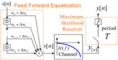
A conventional feedforward equalizer according to the prior art for a high speed interconnect comprises a channel, a feedforward equalization transmitter (FFE Tx) and a 1-bit quantization receiver (Rx) as in FIG. 1, Cable, coaxial cable, backplane, PCB, package, and on-chip wires, with channels ranging from a few centimeters to tens of meters.
When the data rate is in the range of several Gb / s to several tens of Gb / s, the channel has the characteristics of a low-pass filter (LPF) and inter-symbol interference (ISI) .
If the channel loss is large at the Nyquist frequency, inter-signal interference seriously disturbs the communication. Generally, it is known that the loss is small when the channel loss is 0 to 10 dB, is large when the channel loss is 10 to 20 dB, and is very large when the channel loss is 20 to 30 dB. Therefore, channel loss exceeding 30dB is very rare and is known to be extremely difficult to communicate. There is a need to design a feedforward equalization (FFE) transmitter that can ensure reliability under these circumstances.
Referring to FIG. 1, a feedforward equalization transmitter (FFE Tx) has been used as a means to compensate for channel loss to ensure data rate.
The feedforward equalizer (FFE) generally has a tap coefficient w = [w 0 w 1 ... w N ] T and coefficient error Δ w = [Δw 0 ? W 1 ... Is represented by a finite impulse response filter having [Delta] w [ N ] T.
Generally, two to five taps are suitable, and a feed forward equalizer (FFE) having an appropriate tap coefficient w value multiplies the signal y [n] arriving at the receiver Rx by a 2-level (HPF) that compensates for channel loss to produce a pulse amplitude modulation (PAM2) signal. y [n] corresponds to the value arrived at the receiver x [nm] where x [n] is the transmitted data sequence and the signal level is 1 (bit '1') or -1 (bit '0') I have. In this case, m denotes a delay time until x [n] reaches the receiver through the channel.
The 1-bit quantization device of the receiver samples y [n] at period T intervals,


Typical receivers typically rely on eye diagrams obtained through a feedforward equalizer (FFE) because complex coding techniques in these interconnects are expensive and do not have large white noise magnitudes.
Therefore, minimizing the inter-signal interference (ISI) and maximizing the eye diagram are important factors for improving the efficiency of the interconnect system.
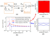
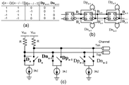
Figure 2 (a) is an illustration of the simplest and most common 2-tap FFE structure.
The wire is modeled as a primary RC circuit with a time constant τ.
The continuous-time pulse response h (t) of the system is given by h (t), u (t) (1-e -t / τ ), where u (t) is the unit step function. Referring to FIG. 2 (b), the continuous time pulse response of this system is shown in a circle and shown as a solid line (Pulse response without FFE).
The discrete-time pulse response h [n] of this channel is equal to h (nT) and can be expressed by the following [Equation 1].
[Equation 1]
h [n] = 0 if n≤0 , or h [n] = (1-e -T / τ) e - (n-1) T / τ if n> 0
n is an integer time index.
h [n]: discrete time impulse response
T: data period
τ: time constant
2 (b), the impulse response h (t) of the system in which the feedforward equalizer (FFE) is not mounted is smaller than the time constant (tau) in the feedforward equalizer (FFE) (ISI tail), which is longer than the impulse response of the system with the ISI.
According to
[Equation 2]
w opt = [1 / (1 + e -T / τ) -e -T / τ / (1 + e -T / τ)] T
w opt : optimized FFE coefficient
T: data period
τ: time constant
When the unit impulse function [delta] [n] is input as x [n], the feedforward equalizer FFE multiplies the transmitted pulse to remove the ISI tail, Undershoot like a long dotted line. As a result, the discrete-time pulse response g [n] of the system equipped with the feedforward equalizer (FFE) is not affected by inter-signal interference as shown by the diamond shape and the solid line in Fig. 2 (b) the eye diagram is completely opened as shown in (d).
The optimal value g opt [n] of the discrete time pulse response g [n], defined as h [n] * w [n], by the characteristics of the Linear Time Invariant (LTI) .
[Equation 3]
g opt [n] = 1 - e - T / τ / 1 + e - T / τ if n = 1, or g [n] = 0 if n ≠ 1.
If the feedforward equalizer (FFE) is not mounted, referring to FIG. 2 (c), the eye diagram is closed, indicating that the feedforward equalizer (FFE) can improve the eye diagram have.
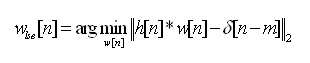
Least-square-error (LSE) is used to determine the feedforward equalizer (FFE) coefficients in various channels. The feedforward equalizer (C-FFE) coefficient w lse [n] according to the prior art which is a solution of the least squares method minimizes the distance between g [n] (= h [n] * w [n]) and δ [nm] And is represented by the following [Expression 4].
[Equation 4]
Using the vector and the matrix representation to obtain the solution of the least squares method, the solution of [Equation 4] can be approximated as [Equation 5]. w lse and h are vectors and are truncated vector representations of w lse [n] and h [n], respectively. h k and δ -m are column vectors with n [n + kl] and δ [nm-1] as the nth element, respectively. And h is H = [ h h -1 h -2 ... h -n ].
[Equation 5]

Generally, the maximum value | v [n] | of the signal transmitted from the feedforward equalizer (FFE) transmitter shown in FIG. 1 has the same constraint as the following Equation (6). Therefore, w lse [n] is normalized as [Equation 7] to satisfy Equation [5].
[Equation 6]
max | v [n] | = | w [0] | + | w [1] | + | w [2] | + ... + | w [N] |? 1
Therefore, to satisfy [Equation 6], w lse [n] can be normalized as in Equation 7 below.
[Equation 7]

In describing an embodiment of the present invention, a conventional feedforward equalization transmitter (conventional FFE) is referred to as C-FFE for convenience, and an equalization transmitter (robust-FFE) that prevents the count error effect of the present invention is referred to as B-FFE .
The hardware implementation of the prior art feedforward equalizer (C-FFE) and the coefficient error associated therewith is as follows.
3 shows a prior art three-tap feed forward equalizer transmitter structure, wherein the flip-flop or latch shown in FIG. 3B is a delay unit (delay unit) of FIG. 1, D). The output of the latch

The differential current mode logic circuit (CML) of FIG. 3 (b)

[Equation 8]
V Tx = (V dd -RI Txp ) - (V dd -RI Txn) = R (I Txn -I Txp)
= R (w [0] x [n] + w [1] x [n-1] + w [
At this time, if V Tx is too large, there is a problem that the transistor operates in an undesired state. Therefore, the same restriction condition as in the above-mentioned [Equation 6] is required.
The transmitter of the feedforward equalizer is vulnerable to a coefficient error caused mainly by variations of nano elements.
That is, the current source and the coefficient | w [n] | shown in FIG. 3 (c) are sensitive to the scatter generated by the nanoscale technology, and such scattering is not easy to control in techniques below micrometers There is a problem that robustness can not be secured.
As shown in Fig. 1, the influence of scattering of the nano device can be modeled as a constant random variable Δ w added to the coefficient w . These phenomena occur much more slowly than data communication over a period of several minutes to several years due to the manufacturing process, changes in circuit operation, and the like, which occur during transmission The random error modeling such as Δw is suitable for the counting error.
Hereinafter, the
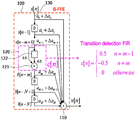
4A, a high-speed interconnect system including a coefficient error robust feed forward equalizer 100 (B-FFE) according to an embodiment of the present invention includes a feedforward equalizer 100 (B-FFE) A
In the case of the
The coefficient error robust feed forward equalizer 100 (B-FFE) according to an embodiment of the present invention includes a receiving
The data change
Specifically, the data
The process of calculating the data transition value by the data change
[Equation 9]
b [n-m] = 0.5x [n-m + 1] -0.5x [n-m] = c [n] * x [n].
x [n]: input data
b [n-m]: Transition of input data
c [n]: Data change detection high-pass filter
b [nm] may have a value of -1, 0, 1, and when b [nm] is -1, x [n] means a change from 1 to -1, and b [nm] , It means that x [n] changes from -1 to 1, and when b [nm] is 0, it means that there is no change of x [n]. That is, b [n-m] includes information that x [n] changes.
As a result, the data transition value computed and output according to Equation (9) becomes -1 when the data input to the data change
In addition, the coefficient error robust feed forward equalizer according to an embodiment of the present invention is capable of calculating the data transition value b [nm] through logic circuit combination of a plurality of consecutive digital bit values in the data stream .
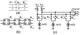
Figure 5 (a) is a truth table representing the expression of [Formula 9] of the 3-tap coefficient error robust feed forward equalizer (FFE-B) according to an embodiment of the invention, two digital bit (D pn - i-1 , D nn -i-1 ). At this time, the two digital bits D pn-i-1 and D nn -i- 1 is configured as shown in Figure 5 (b) using the AND gate.
FIG. 5C is a circuit diagram of a circuit for calculating a product of addition and coefficient of a 3-tap coefficient error robust feed forward equalizer (B-FFE) according to an embodiment of the present invention. Equalizer (C-FFE) It is a circuit of the same type as a CML circuit. Since the cost of the AND gate in the nanoscale CMOS technology is very low, there is an economical effect in constructing the B-FFE according to the present invention.
In the coefficient error robust feed forward equalizer 100 (B-FFE) according to the embodiment of the present invention, tap signals are output from N delay units D as described above, The feedforward equalizer coefficient (a) is preferably configured to be adjustable by a user, which may include a steady state condition (a) and a steady state error coefficient (C-FFE) according to the prior art and the coefficient error robust feed forward equalizer (B-FFE) according to an embodiment of the present invention can be mathematically matched to each other .
In order to explain this in detail, when cleaning up the [formula 9] the above-described [Equation 9] using the vector and the matrix representation can be represented with b [n] as B x x [n], wherein b [n] = [x [n] x [n-1] ... x [n-m + 1], b [nm] b [nm-1] b [nN]] T , x [n] = [x [n] x [n-1] x [n-2] x [nN]] T , and B x is defined as in
[Equation 10]

On the other hand, v of the feed forward equalizer (C-FFE) according to the above-described prior art [n] is because x [n] T w, v [n] = b [n] T a = x [n] T B x T a, and v [n] = x [n ] T using the w, no feed-forward equalizer (C-FFE) any coefficient error robust feed-forward in accordance with the invention equalizer (B-FFE) according to the prior art; And a = [a 0 a 1 ... a n ] T can be derived as shown in [Expression 11] and [Expression 12] below.
[Equation 11]
w = B x T a
[Equation 12]
a = (B x T ) -1 w
The feedforward equalizer coefficient a of the feedforward equalizer 100 (B-FFE) according to an embodiment of the present invention can be calculated using Equation 11 and
As described above, the scattering effect of the element generated in the coefficient error robust feed forward equalizer (B-FFE) according to the present invention is such that the constant random coefficient error? A is smaller than the feed forward equalizer coefficient a Lt; / RTI >
Hereinafter, robustness of a coefficient error robust feed forward equalizer (B-FFE) according to the present invention will be described. A 2-tap coefficient error robust feed forward equalizer in a first order RC channel according to an embodiment of the present invention will be described as an example.
Since the feedforward equalizer (FFE) is an LTI system, it can analyze the effect of a count error from the perburbation of the pulse response.
By substituting 0 for the nominal coefficient of the feedforward equalizer (FFE), the perturbation y [n], y [n], can be obtained. That is, by replacing w [n] shown in FIG. 1 with 0, it is possible to derive [Expression 13] for the feed forward equalizer (C-FFE) according to the prior art.
[Equation 13]

H ? W [m] [n], which is defined as ? W [m] h [nm] in Equation 13 above is the influence of the coefficient error Δw [m] on Δy [n] .
Here, the reference to [formula 13], Δy [n] is the coefficient error because the values adding up all the influence of Δw [m], the perturbation of the feed forward equalizer (FFE) system all h as a normal pulse response Δw [m] [n]. Therefore, h ? W [m] [n] can be defined as a coefficient error pulse by? W [m]. Referring to FIG. 4, the pulse response change Δy [n] of the coefficient error robust feed forward equalizer (B-FFE) according to the present invention can be derived as:
[Equation 14]

In Equation (14), h ? A [m] [n] is a coefficient error pulse response by? A [m]. When 0≤k≤m-1 h Δa [k] [n] is a Δa [k] h [nk], when m≤k≤N h Δa [k] [n ] = Δa [k] h [ nk] * c [n] = 0.5? a [k] (h [nk-m + 1] -h [nkm]).
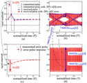
6 is a diagram showing the result of simulating the influence of? W [0] on a 2-tap C-FFE according to the prior art mounted to compensate for loss of the primary RC channel. 6 (a), the pulse response without inter-signal interference (ISI) can be confirmed. As a result, as shown by the solid line in FIG. 6 (b) eye diagram.
However, if the pulse to which the count error? W [0] is transmitted and the response is slightly changed from the steady state as in 2 or 4 of Fig. 6 (a), the spread of the upper and lower portions of the eye diagram A phenomenon occurs. That is, the maximum value of the eye diagram spread generated in FIG. 6 (b) is expressed by Δy Δw [0] [n] expressed by Δy [n] Is equal to the maximum value of the eye diagram of FIG.
If you define the height of the child (eye) decreases when the only error of Δw [0] to Δv eye, Δw [0], Δv eye, Δw [0] is 2max | represented by | Δy Δw [0] [n ] .
As shown in Figure 6 (c), h Δw [ 0] [n] is because RC response exponentially decreasing, max | Δy Δw [0] [n] | is for all the n x [n] = 1 or -1. Assuming that the error rate is? 0 , the coefficient error? W [0] can be represented by? 0 w [0], so that the following equation can be obtained from [Expression 1], [Expression 2], [Expression 13] max |? y ? w [0] [n] |.
[Equation 15]
max [Delta] w [0] [n] | = max |
= | Δw [0] | Σ∀ n h [n] = | Δw [0] | = |
Further, when the definition of? W [0] is applied to? W [1], max |? Y ? W [1] [n] | can be derived as shown in the following equation.
[Equation 16]
max | Δy Δw [1] [ n] | = max | Δw [1] h [n-1] * x [n] | = | Δw [1] | Σ∀ n h [n]
= | Δw [1] | = | α 1 | eT / τ / (1 + e- T / τ )
In Fig. 6 (d),? W [0] is -20% of w [0] which is 0.6 at -0.12. Thus, when T is 0.4?, Max |? Y? W [0] [n] | becomes 0.12 and the height of the reduced eye? V eye ,? W [0] = 0.4-0.16 = 2max |? Y? W [0] [n] | = 0.12? 2 = 0.24.
Fig. 7 is a graph showing a case where a coefficient error robust feed forward equalizer (B-FFE) according to the present invention is mounted instead of the feedforward equalizer (C-FFE) according to the prior art in Fig. 6, a [1]) in the first embodiment. In the steady state, the operation of the feedforward equalizer (C-FFE) according to the prior art and the coefficient error robust feed forward equalizer (B-FFE) according to the present invention are the same, It is possible to obtain a pulse response without ISI and referring to the solid line in Fig. 7 (b), it can be seen that there is no spreading of the eye diagram.
Referring to FIG. 7 (a), Δa [1] changes the pulse response and causes the eye diagram to spread as shown by the dotted line in FIG. 7 (b).
However, since the coded error robust feed forward equalizer (B-FFE) according to the present invention operates as a high-pass filter (HPF) shown in FIG. 4, c [n] , The perturbation of the transmitted pulse is modified to reduce h [Delta] a [ 1] [n].
As a result, comparing Fig. 7C and Fig. 6C, h ? A [1] [n] in Fig. 7C is significantly lower than h ? W [0] [n] It can be seen that the spread of the eye diagram in Figs. 7 (d) and 7 (b) is much smaller than that in Figs. 6 (d) and 6 (b).
Wherein when the [formula 15] and the error rate in analogy to α n in the Formula 16] assumed to be β n using that Δa [m] = β n a [m], as follows: [Formula 17] and [formula 18] h [Delta] a [m] [n].
[Equation 17]

[Equation 18]

c [n] does not change h ? a [0] [n]. Therefore, h Δa [0] [n ] is h Δw [0] [n] , h Δw [1] [n] the same decreases exponentially with, and reduce the perturbation caused in the h Δa [1] [n] The effect does not appear. However, since the steady state value a [0] has a small value as shown in [Equation 19], | Δa [0] | is larger than | Δw [0] |, | Δw [1] |, and | Δa [ Generally, it has a much smaller value.
[Expression 19]
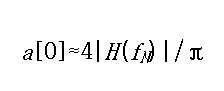
H (f): Frequency response of the channel
f N : Nyquist frequency
[Equation 19] can be derived as follows. First, x [n] = '... , 1, -1, -1, -1, 1, ... 'Makes a square wave of v (t) (a continuous-time signal corresponding to v [n]). Therefore, v 1st (t) = 4 sin (2fNt) / π, which is the first harmonic signal (1 st harmonic) of v (t) Since the channel is a low-pass filter (LPF), at the receiver, y 1 st (t) (the first harmonic signal of the continuous-time signal y (t) corresponding to y [n]) dominates. When the channel distortion is well compensated, | y 1st (t) | ≒ a so approximation is possible to [0] is the y 1st (t) ≒ a [ 0] (2πf N t) sin. At this time, at the Nyquist frequency f N , | y 1 (t) | = | v 1 (t) || H (f N ) |
According to the above equation [19], a [0] value can be predicted within an error of about 20% and a [0] is much smaller than other coefficients. In this embodiment, | Δw [0] | is 0.12, | Δw [1] | is 0.08, | Δa [1] | is larger than that for the same 20% Is 0.16.
The worst perturbation as shown in the following [Expression 20] and [Expression 21] is performed by using Expression 14, Expression 17 and Expression 18 expressing the influence of DELTA a [0] and DELTA a [ the worst perturbation value max |? y ? a [0] [n] | And max |? Y? A [1] [n] |.
[Equation 20]
0 [n] | = max |? a [0] h [n] * x [n] |
= | Δa [0] | Σ∀ n h [n] = | Δa [0] | = |
[Equation 21]
max | Δy Δa [1] [ n] | = max | Δa [1] h [n] * c [n] * x [n] |
= 0.5 | Δa [1] | {h [1] -Σ∀ n≥2 (h [n] - h [n-1])} = | Δa [1] | (1-e -T / τ)
= 2 | β 1 | e -T / τ (1-e -T / τ) / (1 + e -T / τ)
7, the Δa [1] is 0.16, the max | Δy Δa [1] [n] | is approximated to 0.05, and the eye size is approximately 0.29. This value is 80% higher than the value of 0.16 in FIG. Further, max |? Y? A [1] [n] | is calculated as max |? Y ? W [0] [n] (= 0.12) 56%, max |? Y ? W [1] [n] | (= 0.08).
A method for improving the robustness of a coefficient error robust feed forward equalizer (B-FFE) according to the present invention, which is explained through the analysis of the frequency domain, is as follows.
Referring to FIG. 1, the continuous-time perturbation function p ? W [m] (t) of a pulse transmitted by ? W [m] is derived as in Equation 22 below, The spectrum (P ? W [m] (f)) of p ? W [m] (t) when ? [N] is input as x [n]
[Equation 22]
p ? w [m] (t) =? w [m]? T (t-mT)
[Equation 23]
P Δw [m] (f) = Δw [m] Λ T (f) e - j2 π fmT = Λ Δw [m], T (f) e - j2 π fmT
In Equation 22, Π T (t) is defined as Π T (t) = 1 when 0 ≤ t <T and Π T (t) = 0 for all other t.
In the [formula 23], Λ T (f) = Tsinc (fT) e -jπ fT is the Fourier transform of Π T (t) Λ Δw [ m], T (f) = Δw [m] Λ T (f )to be. Further, the continuous time channel response h ? W [m] (t) and its spectrum H ? W [m] (t) of p ? W [m] (t) are obtained from h (t), the above- f) is derived as shown in the following equations (24) and (25).
[Equation 24]
h ? w [m] (t) = (h * p ? w [m] ) (t)
[Equation 25]
H Δw [m] (f) = H (f) P Δw [m] (f) = H (f) Λ Δw [m], T (f) e -j2πfmT
The [formula 25] in Λ Δw [m], T ( f) is with respect to a sequence of x [n] = δ [n] Δw [m] and x (t) = Π T ( t) Π Δw caused by [m] and T (t) = Δw [m] Π T (t). Therefore, Π Δw [m], T (t), Λ Δw [m], and T (f) are defined as input error pulses and their spectra by Δw [m].
On the other hand, the continuous-time transmission error pulse p ? A [m] (t) by? A [m] in the coefficient error robust feed forward equalizer (B-FFE) according to the present invention and its spectrum are given by [ Is derived as shown in [Equation 27].
[Equation 26]

[Equation 27]

In this case, c (t) = 0.5δ ( t) -0.5δ (tT) is the continuous-time impulse response of c [n], C (f ) = jsin (πfT) e (-jπ fT) is c (t ) ≪ / RTI > Since the continuous time count error pulse response hΔa [m] (t) by Δa [m] is (h * p Δa [m] ) (t), H (f) and P Δa [m] the spectrum H ? a [m] (f) of h ? a [m] (t) can be derived as shown below.
[Equation 28]

The common expressions Λ Δcoeff [m], T (f) = Δ coeff [m] Λ T (f) through the
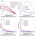
8 (a) to 8 (c) show a two-tap feed forward equalizer (C-FFE) according to the prior art and a coefficient error robust according to the present invention in a primary RC channel in which a loss of 18 dB occurs in f N A graph comparing various spectra of a feedforward equalizer (B-FFE).
Referring to Figure 8 (a), the coefficient error pulse spectrum LAMBDA of the input stage reference of the prior art feed forward equalizer (C-FFE) and the count error robust feed forward equalizer (B-FFE) Δw [0], T (f ), Λ Δw [1], T (f), Λ Δa [0], T (f), and Λ Δa [1], T ( f)) is the lowest frequency energy It has a concentrated sinc function form. 8 (b) shows a spectrum of C (f) which is a high-pass filter (HPF). C (f) is less than P Δw [0] (f) and P Δw [1] (f) As shown in 8 (a) also attenuated the amount of the low frequency P Δa [1] (f) Size. Referring to Fig. 8 (b), the spectrum of H (f) sharply decreases as the frequency increases. Thus, as shown in the [formula 28] C (f) H ( f) overall has a smaller size in the frequency range, As shown in FIG. 8 H Δa [1] (f ) is H Δw [0] (f) or H is much smaller than Δw [1] (f). The H ? A [0] (f) not filtered by the high pass filter (HPF) C (f) is also smaller than H ? W [0] (f) or H ? W [1] (f) .
The coefficient error robust feed forward equalizer according to the present invention is effective when channel robustness is important due to a large dispersion of channels. Fig. 8 (d) shows the result of simulating the spectrum of Fig. 8 (c) in a 36 dB channel with a larger loss. H Δa [0] (f) and H Δa [1] (f) is 8 than in the 8 (c) also when compared with H Δw [0] (f) and H Δw [1] (f) ( d), it can be seen that the value is smaller. Therefore, the coefficient error robust feed forward equalizer (B-FFE) according to the present invention provides a much better improvement effect in a lossy channel.
Eye diagrams are widely used to measure the quality of communication. Thus, in order to quantify the robustness of the feedforward equalizer (FFE), the eye sensitivity to an n-th feed forward equalizer (FFE) coefficient κ [n] k [n] . S k [n] is obtained by dividing the reduction rate of the eye height reduction value Δv eye, Δκ [n] by Δκ [n] from the optimal eye height v eye by the error rate of κ [n] , Where the other coefficient error is replaced by zero.
[Equation 29]

If the eye sensitivity of the feedforward equalizer (FFE) is large, the eye diagram of the feedforward equalizer (FFE) is more sensitive to counting errors. Thus, eye sensitivity is useful as a measure of robustness.
A 2-tap feedforward equalizer (FFE) for the primary RC channel has a theoretically perfect eye in the absence of any perturbation and has a child height (g) according to FIG. 6 and g opt [n] v eye ) is determined by 2g opt [1] as in the following [Expression 30].
[Equation 30]
v eye = 2 (1 - e - T / τ ) / (1 + e - T /
? W [m] = -2max |? Y? W [m] [n], as described above. Thus, w [0] and w [1] has the same sensitivity as the following [Expression 31] and [Expression 32].
[Equation 31]

[Equation 32]

T << πτ a case, the [equation 31] and [equation 32] is a Taylor series (e -T / τ ≒ 1- T / τ) and a channel frequency response at f N (H (f N) = 1 / (1 + j2? F N ?)? T / (j??) By the following equations (33) and (34).
[Equation 33]

[Equation 34]

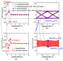
9 shows the eye sensitivity of the prior art 2-tap feed forward equalizer (C-FFE) for a primary RC channel and the count error robust feed forward equalizer (B-FFE) f N ). Referring to FIG. 9, it can be seen that the above equations (33) and (34) are similar to the equations (31) and (32), respectively.
As the denominator (1-e -T / τ ) converges to zero, the channel loss and S w [0] and S w [1] towards almost infinite linearly . For T = τ, the channel loss is 10 dB, S w [0] = 1.58, and S w [1] = 0.58. On the other hand, when T = 0.1τ, the channel loss is 30dB, S w [0] = 10.5, and S w [1] = 9.5. That is, when T = 0.1τ, the worst eye sensitivity is increased by 6.6 times as compared with T = τ.
In general, if the data rate is fast and the channel loss is large, the eye sensitivity is also very large, and the high eye sensitivity means that the count error amplifies. Thus, even a very small count error can cause the eye diagram to be closed, so designers must strictly control variations in coefficients even when they consume excessive hardware area and power.
A w [0] error of only 1.9% can reduce the height of the eye by 20%, and if T = 0.1, 12.6% w [0] Reduce. Therefore, the design cost of the FFE is high in a very lossy channel with a channel loss of 30 dB or more.
The count error robust feed forward equalizer (B-FFE) according to the present invention has the effect of improving eye sensitivity in a channel with a very high loss. The optimal error robust feed forward equalizer (B-FFE) coefficient a opt for the primary RC channel according to the present invention is calculated using Equation (2) and Equation (12) .
[Equation 35]
a opt = (B x T) -1 w opt = [(1-e -T / τ) / (1 + e -T / τ) 2e -T / τ / (1 + e -T / τ)] T
The eye sensitivity of the coefficient error robust feed forward equalizer (B-FFE) according to the present invention is derived from h ? A [m] [n] of [Expression 17] and [Expression 18]. Is | Δy Δa [0] [n] | | the [formula 14] and [formula 17] are from max | can be seen that, Δv eye = -2max | | Δa [0] Δy Δa [0] [n] Therefore,? V eye = -2 |? A [0] |. Also, v is an eye = 2g opt [n] and g opt [n] = a [ 0] , because it is eye v 2a = [0]. Therefore, the eye sensitivity of [ Delta] a [0] (S a [0] ) can be derived by [Equation 36].
[Equation 36]

Figure 9 shows that S w [0] and S w [1] are increased but S a [0] = 1 when the data rate increases. Therefore, even if the data rate is very high, the influence of [Delta] a [0] is not amplified by the eye sensitivity of the count error robust feed forward equalizer (B-FFE) according to the present invention.
max | Δy Δa [1] [ n] | = | Δa [1] | (1-e -T / τ) is derived from the above [formula 14] and [formula 18], Δv eye, Δa [ 1] = 2max | Δy Δa [1] [n] | = 2 | Δa [1] | (1-e -T / τ ). If the Taylor series approximation is applied to [Expression 30] and [Expression 35], S a [1] is simplified as shown in Expression (37) below.
[Equation 37]

As can be seen from FIGS. 9 and 37, when the data rate increases, S a [1] increases but converges to '2'.
9 is a graph showing the eye sensitivity of a prior art feedforward equalizer (C-FFE) according to the data rate and a count error robust feed forward equalizer (B-FFE) according to the present invention. The sensitivity of the feed forward equalizer (C-FFE) according to the prior art increases toward infinity and the sensitivity of the count error robust feed forward equalizer (B-FFE) according to the present invention converges to 1 or 2 Able to know.
Thus, the difference in eye sensitivity, which is the degree of improvement in the robustness of the prior art feed forward equalizer (C-FFE) and the inventive count error robust feed forward equalizer (B-FFE), increases infinitely . (B-FFE) according to the present invention when the channel loss is 10 dB (τ / T = 1), 30 dB (τ / T = 10), and 40 dB The worst eye sensitivities are S a [0] = 1, S a [1] = 1.8, and S a [1] = 1.9. This result is 1.54 times, 5.9 times, and 17 times the worst case sensitivity of the feedforward equalizer (C-FFE) according to the above-mentioned prior art, 1.54, 10.6, and 32.3, respectively .
Hereinafter, in order to clarify the eye sensitivity analysis, the eye sensitivity of a feedforward equalizer (C-FFE) according to the prior art and a coefficient error robust feed forward equalizer (B-FFE) Numerical analysis will be explained.
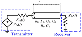
The actually used channel can be modeled as a lossy transmission line as shown in FIG. The transfer function of the lossy transmission line is expressed by the
[Expression 38]

[Equation 39]

[Equation 40]

[Equation 41]

(F) is the frequency response of the channel of length l, Z c (f) is the characteristic impedance of the channel, and Z Tx (f) is the channel impedance of the channel. In the
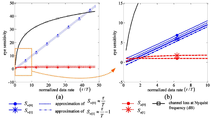
11 shows the eye sensitivity of a 5-tap feed forward equalizer (C-FFE) according to the prior art and a 5-tap coefficient error robust feed forward equalizer (B-FFE) according to the present invention in a 40- And the channel loss at the Nyquist frequency.
To calculate the eye sensitivity, we first mathematically calculate the eye height reduced by the 10% count error. The worst case analysis is used for sequence lengths with a bit-error-rate (BER) of 10 -18 . Several closed eyes are indicated by the dotted lines in Fig. In order to describe a closed eye diagram, the difference between the minimum signal size of bit '1' and the maximum signal size of bit '0' is defined as the height of the child. If the child is closed, the height of the defined child is negative, Indicates how much worse the signal level should be improved to open the eye diagram.
Referring to FIG. 11, the eye sensitivity of the count error robust feed forward equalizer (B-FFE) according to the present invention is much smaller than that of the prior art feed forward equalizer (C-FFE). The worst case sensitivity (S a [2] ) of the coefficient error robust feed forward equalizer (B-FFE) according to the present invention is 3.55 when the Nyquist channel loss is about 40 dB and the data rate is 10 Gb / , And the eye sensitivity (Sw [1]) of the feedforward equalizer (C-FFE) according to the prior art is 25.7. That is, according to the present invention, there is an effect of improving the eye sensitivity by about 7 times or more as compared with the feed forward equalizer (C-FFE) according to the prior art, and controlling w [1] Should be. If a 20% eye size reduction is allowed, w [1] requires at least 0.77% accuracy, while a [2] requires an accuracy of 5.63%. Since the method for securing 0.77% accuracy in nanotechnology is very expensive, prior art feed forward equalizers operating at 10 Gb / s are not practical. However, since the present invention requires only 5.63% accuracy under the same conditions, 10 Gb / s can be easily achieved.
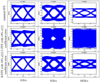
Figure 12 is an eye diagram at 5 Gb / s, 7 Gb / s and 8.5 Gb / s selected from Figure 11, assuming all 10% errors. Nyquist channel losses are 20dB, 27.9dB and 33.6dB, respectively. (B-FFE) according to the present invention has a slightly deteriorated form in the steady-state eye diagram while the prior art feed forward equalizer (C-FFE) The eye diagram of FIG. That is, according to the present invention, it is possible to overcome the limit of robustness occurring in a high-speed interconnect.
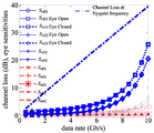
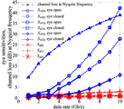
(C-FFE) according to the prior art and a 3-tap coefficient error robust feed forward equalizer (B-FFE) according to the invention in a 3.5 cm silicon interposer package. (C-FFE) according to the prior art, and a coefficient error robust feed forward equalizer (B-FFE) according to the present invention, as well as the channel loss at the Nyquist frequency It is a graph showing the eye sensitivity according to the data rate. The length of the channel is as short as 3.5 cm, but since the channel width is narrow, the channel loss is as high as 38.8 dB at 10 Gb / s, resulting in serious rigidity problems. At 10 Gb / s, the count error robust feed forward equalizer (B-FFE) according to the present invention improves the
FIG. 14 is a graph showing an eye diagram of a count error robust feed forward equalizer (B-FFE) according to the present invention and a conventional feed forward equalizer (C-FFE) in a steady state when a 10% / s, 5 Gb / s and 10 Gb / s. At this time, Nyquist channel loss is 9 dB, 27.5 dB, and 38.8 dB at 1 Gb / s, 5 Gb / s, and 10 Gb / s, respectively. 14, the eye diagram of a prior art feedforward equalizer (C-FFE) quickly closes, whereas a child of a count error robust feed forward equalizer (B-FFE) according to the present invention has a data rate Even if it increases, it keeps the opened eye diagram. Referring to FIGS. 13 and 14, according to the present invention, there is an effect of improving the robustness against the count error, and particularly, the data speed is high, which is effective in ensuring robustness in a severe problem of robustness.
100: Feed forward equalizer
110: first operator
120: Data change detection filter
121: second operator
200: channel
300: receiver
Claims (7)
N delay units (D) connected in series with the receiver (130);
A first calculator (110) for summing the tap signals output from the N delay units (D), respectively; And
A data change detection filter (120) for outputting a data transition value (b) based on a change of the input data (x);
A coefficient error robust feedforward equalizer comprising:
Between the receiving end and the receiving end and between the delay unit D at the leading end connected to the receiving end,
(D) between adjacent two delay units (D) of the N delay units
And a final-stage delay unit (D) connected adjacent to the first operator (110) and the first operator (110).
The data change detection filter 120 includes one delay unit 122 and a second operator 121 connected to the one delay unit 122,
The second calculator 121 calculates a current value x [nm] output from the one delay unit 122 and a previous value x [n-m + 1] input to the one delay unit 122, (B [nm]) based on the data transition value (b [nm]).
The data change detection filter (120) calculates the data transition value based on the following equation:
b [nm] = 0.5x [n-m + 1] -0.5x [nm]
Wherein n and m are integers and n > m
Wherein the data transition value b [nm] is calculated through logic circuit combination of a plurality of consecutive digital bit values in the data stream.
Wherein the data change detection filter (120) is a high pass filter (HPF).
Wherein the tap signal comprises a feedforward equalizer coefficient (a), and wherein the feedforward equalizer coefficient (a) is adjustable by a user.
Priority Applications (2)
| Application Number | Priority Date | Filing Date | Title |
|---|---|---|---|
| US14/889,814 US9503293B2 (en) | 2013-05-07 | 2014-04-30 | Coefficient error robust feed forward equalizer |
| PCT/KR2014/003841 WO2014182000A1 (en) | 2013-05-07 | 2014-04-30 | Coefficient error robust feed forward equalizer |
Applications Claiming Priority (2)
| Application Number | Priority Date | Filing Date | Title |
|---|---|---|---|
| KR1020130051427 | 2013-05-07 | ||
| KR20130051427 | 2013-05-07 |
Related Child Applications (1)
| Application Number | Title | Priority Date | Filing Date |
|---|---|---|---|
| KR1020150173193A Division KR101709910B1 (en) | 2013-05-07 | 2015-12-07 | A coefficient error robust transmit feed forward equalization |
Publications (1)
| Publication Number | Publication Date |
|---|---|
| KR20140132277A true KR20140132277A (en) | 2014-11-17 |
Family
ID=52453346
Family Applications (2)
| Application Number | Title | Priority Date | Filing Date |
|---|---|---|---|
| KR20140052097A KR20140132277A (en) | 2013-05-07 | 2014-04-30 | A coefficient error robust transmit feed forward equalization |
| KR1020150173193A KR101709910B1 (en) | 2013-05-07 | 2015-12-07 | A coefficient error robust transmit feed forward equalization |
Family Applications After (1)
| Application Number | Title | Priority Date | Filing Date |
|---|---|---|---|
| KR1020150173193A KR101709910B1 (en) | 2013-05-07 | 2015-12-07 | A coefficient error robust transmit feed forward equalization |
Country Status (2)
| Country | Link |
|---|---|
| US (1) | US9503293B2 (en) |
| KR (2) | KR20140132277A (en) |
Cited By (1)
| Publication number | Priority date | Publication date | Assignee | Title |
|---|---|---|---|---|
| KR102568428B1 (en) * | 2022-04-01 | 2023-08-18 | 한양대학교 산학협력단 | Transmitter comprising feed forward equalization |
Families Citing this family (5)
| Publication number | Priority date | Publication date | Assignee | Title |
|---|---|---|---|---|
| GB2587962B (en) * | 2018-04-12 | 2022-12-14 | Rockley Photonics Ltd | Optical engine |
| US10243762B1 (en) | 2018-04-16 | 2019-03-26 | Macom Connectivity Solutions, Llc | Analog delay based fractionally spaced n-tap feed-forward equalizer for wireline and optical transmitters |
| US10924310B2 (en) | 2018-09-10 | 2021-02-16 | International Business Machines Corporation | Transmitter with fully re-assignable segments for reconfigurable FFE taps |
| KR20210038142A (en) | 2019-09-30 | 2021-04-07 | 삼성전자주식회사 | Electronic device including equalizing circuit and operating method of the electronic device |
| US20210126764A1 (en) * | 2019-10-29 | 2021-04-29 | International Business Machines Corporation | Time dependent line equalizer for data transmission systems |
Family Cites Families (7)
| Publication number | Priority date | Publication date | Assignee | Title |
|---|---|---|---|---|
| US6240133B1 (en) * | 1998-02-05 | 2001-05-29 | Texas Instruments Incorporated | High stability fast tracking adaptive equalizer for use with time varying communication channels |
| WO2002039684A2 (en) | 2000-11-13 | 2002-05-16 | Primarion, Inc. | Method and circuit for pre-emphasis equalization in high speed data communications |
| WO2004034078A2 (en) | 2002-10-08 | 2004-04-22 | Broadcom Corporation | A high speed data link with transmitter equalization and receiver equalization |
| EP1709758A4 (en) * | 2003-12-16 | 2007-07-18 | California Inst Of Techn | Deterministic jitter equalizer |
| TWI271934B (en) | 2005-11-04 | 2007-01-21 | Realtek Semiconductor Corp | Equalizer and equalizing method thereof |
| JPWO2009013814A1 (en) * | 2007-07-24 | 2010-09-24 | 富士通株式会社 | Semiconductor device |
| JP5487996B2 (en) | 2010-01-25 | 2014-05-14 | 富士通株式会社 | Adaptive equalizer and adaptive equalization method |
-
2014
- 2014-04-30 US US14/889,814 patent/US9503293B2/en active Active
- 2014-04-30 KR KR20140052097A patent/KR20140132277A/en active Application Filing
-
2015
- 2015-12-07 KR KR1020150173193A patent/KR101709910B1/en active IP Right Grant
Cited By (2)
| Publication number | Priority date | Publication date | Assignee | Title |
|---|---|---|---|---|
| KR102568428B1 (en) * | 2022-04-01 | 2023-08-18 | 한양대학교 산학협력단 | Transmitter comprising feed forward equalization |
| WO2023191565A1 (en) * | 2022-04-01 | 2023-10-05 | 한양대학교 산학협력단 | Transmitter comprising feed forward equalizer |
Also Published As
| Publication number | Publication date |
|---|---|
| KR20160003579A (en) | 2016-01-11 |
| KR101709910B1 (en) | 2017-02-24 |
| US20160105298A1 (en) | 2016-04-14 |
| US9503293B2 (en) | 2016-11-22 |
Similar Documents
| Publication | Publication Date | Title |
|---|---|---|
| KR101709910B1 (en) | A coefficient error robust transmit feed forward equalization | |
| US6266379B1 (en) | Digital transmitter with equalization | |
| Schrader et al. | Wireline equalization using pulse-width modulation | |
| US20010043649A1 (en) | Analog N-tap FIR receiver equalizer | |
| CN110858824B (en) | Pre-compensator based quantization for clock recovery | |
| US7411422B2 (en) | Driver/equalizer with compensation for equalization non-idealities | |
| Wang et al. | Analysis and optimization of combined equalizer for high speed serial link | |
| Yuminaka et al. | Multiple-valued signaling for high-speed serial links using Tomlinson-Harashima precoding | |
| US9264276B1 (en) | Adaptations for partial response summation node embedded FPGA transceiver | |
| Agarwal et al. | A 5-Gb/s adaptive CTLE with eye-monitoring for multi-drop bus applications | |
| Baprawski | Serdes system ctle basics | |
| Delshadpour et al. | Effect of Equalization Bandwidth and Linearity on NRZ and PAM4 Eye Diagram | |
| Yuminaka et al. | Multiple-valued data transmission based on time-domain pre-emphasis techniques in consideration of higher-order channel effects | |
| US10735039B1 (en) | Removal of channel impairments due to skew and channel asymmetry with a composite filter | |
| Yuminaka et al. | Data-dependent time-domain pre-emphasis techniques for high-speed data transmission | |
| Duvvuri et al. | 100-Mbps transceiver for enhanced MIL-STD-1553 | |
| Thuneibat | A General Guide for Communication System Engineers to Improve QoS | |
| Al-Taee et al. | A power-efficient 2-dimensional on-chip eye-opening monitor for Gbps serial links | |
| Ševčík et al. | Time-domain pre-distortion technique using raised cosine shaping for high-speed serial signaling | |
| Yuminaka et al. | Time-Domain Pre-Emphasis Techniques for Multiple-Valued Data Transmission. | |
| Ševčík et al. | Optimized Signaling Method for High-Speed Transmission Channels with Higher Order Transfer Function | |
| Franklin et al. | An improved channel model for ADSL and VDSL systems | |
| Ševčík et al. | Application of pulse-width modulated pre-emphasis in closely-spaced transmission lines with additional discontinuities | |
| Yuminaka et al. | High-Speed Multiple-Valued Data Transmission Based on Time-domain Pre-Emphasis Techniques | |
| MOLU | EQUALIZERS FOR HIGH-SPEED SERIAL, LINKS |
Legal Events
| Date | Code | Title | Description |
|---|---|---|---|
| A201 | Request for examination | ||
| E902 | Notification of reason for refusal | ||
| AMND | Amendment | ||
| E601 | Decision to refuse application | ||
| AMND | Amendment | ||
| A107 | Divisional application of patent |