KR20140130552A - Shot peening device - Google Patents
Shot peening deviceInfo
- Publication number
- KR20140130552A KR20140130552A KR1020147028020A KR20147028020A KR20140130552A KR 20140130552 A KR20140130552 A KR 20140130552A KR 1020147028020 A KR1020147028020 A KR 1020147028020A KR 20147028020 A KR20147028020 A KR 20147028020A KR 20140130552 A KR20140130552 A KR 20140130552A
- Authority
- KR
- South Korea
- Prior art keywords
- projection
- work
- short
- projecting
- projected
- Prior art date
Links
Images


Classifications
-
- B—PERFORMING OPERATIONS; TRANSPORTING
- B24—GRINDING; POLISHING
- B24C—ABRASIVE OR RELATED BLASTING WITH PARTICULATE MATERIAL
- B24C9/00—Appurtenances of abrasive blasting machines or devices, e.g. working chambers, arrangements for handling used abrasive material
- B24C9/006—Treatment of used abrasive material
-
- B—PERFORMING OPERATIONS; TRANSPORTING
- B24—GRINDING; POLISHING
- B24C—ABRASIVE OR RELATED BLASTING WITH PARTICULATE MATERIAL
- B24C1/00—Methods for use of abrasive blasting for producing particular effects; Use of auxiliary equipment in connection with such methods
- B24C1/10—Methods for use of abrasive blasting for producing particular effects; Use of auxiliary equipment in connection with such methods for compacting surfaces, e.g. shot-peening
-
- Y—GENERAL TAGGING OF NEW TECHNOLOGICAL DEVELOPMENTS; GENERAL TAGGING OF CROSS-SECTIONAL TECHNOLOGIES SPANNING OVER SEVERAL SECTIONS OF THE IPC; TECHNICAL SUBJECTS COVERED BY FORMER USPC CROSS-REFERENCE ART COLLECTIONS [XRACs] AND DIGESTS
- Y02—TECHNOLOGIES OR APPLICATIONS FOR MITIGATION OR ADAPTATION AGAINST CLIMATE CHANGE
- Y02P—CLIMATE CHANGE MITIGATION TECHNOLOGIES IN THE PRODUCTION OR PROCESSING OF GOODS
- Y02P70/00—Climate change mitigation technologies in the production process for final industrial or consumer products
- Y02P70/10—Greenhouse gas [GHG] capture, material saving, heat recovery or other energy efficient measures, e.g. motor control, characterised by manufacturing processes, e.g. for rolling metal or metal working
Abstract
장치의 대형화를 억제하면서, 회수한 투사재와 이물질을 고정밀도로 분리할 수 있는 쇼트 처리 장치이며, 워크(W)에 투사재를 투사하는 투사기(42)와, 상기 투사기에 의해 투사된 투사재를 회수하는 회수 기구(52, 54)와, 회수된 투사재에 상향의 기류를 닿게 하면서, 상기 회수된 투사재를 자유 낙하시키고, 상기 회수된 투사재에 혼입되어 있는 이물질을, 상기 회수된 투사재로부터 분리하는 풍력 선별 기구(62)를 구비하고 있는 쇼트 처리 장치.A shot processing apparatus capable of highly accurately separating a collected projection material and foreign matter while suppressing enlargement of the apparatus is provided with a projector (42) for projecting a projection material to a work (W), and a projection device A recovery mechanism (52, 54) for recovering the collected projected material; and a recovery mechanism (52, 54) for recovering the collected projected material, while bringing the upwardly directed airflow into contact with the recovered projected material, And a wind-power separating mechanism (62) for separating the wind from the wind.

Description
본 발명은 개략적으로는, 쇼트 처리 장치에 관한 것으로, 상세하게는, 워크인 투사재를 회수하고, 이 회수된 투사재로부터 이물질을 분리하는 쇼트 처리 장치에 관한 것이다.The present invention relates generally to a shot processing apparatus, and more particularly, to a shot processing apparatus for recovering a projection material as a workpiece and separating foreign matter from the collected shot material.
쇼트 처리 장치로서, 워크에 투사된 투사재를 회수하고, 이 회수된 투사재로부터 이물질을 분리하는 분리 기구를 구비한 장치가 알려져 있다(예를 들어, 특허문헌 1 참조). 이와 같은 장치에서는, 예를 들어 진동체기 등을 사용하여 투사재로부터 이물질을 분리하고 있다.As a shot processing apparatus, there is known an apparatus having a separation mechanism for collecting a projection material projected on a work and separating foreign matter from the collected projection material (see, for example, Patent Document 1). In such an apparatus, for example, a foreign object is separated from the projection material by using a vibrating body or the like.
그러나, 이와 같은 장치에서는, 내부에 진동체기가 배치되기 때문에 장치가 대형화되어 버린다.However, in such an apparatus, since the vibrating body is disposed inside, the apparatus becomes large.
본 발명은 상기 과제를 해결하기 위해 이루어진 것으로, 장치의 대형화를 억제하면서, 회수한 투사재와 이물질을 고정밀도로 분리할 수 있는 쇼트 처리 장치를 제공하는 것을 목적으로 한다.An object of the present invention is to provide a shot processing apparatus capable of highly precisely separating a collected projection material and foreign matter while suppressing the size increase of the apparatus.
본 발명에 따르면,According to the present invention,
워크에 투사재를 투사하는 투사기와,A projector for projecting the projection material onto the work,
상기 투사기에 의해 투사된 투사재를 회수하는 회수 기구와,A recovery mechanism for recovering the projection material projected by the projector,
회수된 투사재에 상향의 기류를 닿게 하면서, 상기 회수된 투사재를 자유 낙하시키고, 상기 회수된 투사재에 혼입되어 있는 이물질을, 상기 회수된 투사재로부터 분리하는 풍력 선별 기구를 구비하고 있는 것을 특징으로 하는 쇼트 처리 장치가 제공된다.And a wind power separating mechanism for freely dropping the recovered projecting material while separating the collected projecting material from the recovered projecting material while bringing the upwardly directed airflow into contact with the recovered projecting material A short processing device is provided.
이와 같은 구성의 쇼트 처리 장치에 의하면, 투사기에 의해 투사된 후에 회수된 투사재(투사재와 이물질의 혼합물)를 자유 낙하시킴과 함께, 상향의 기류가 닿음으로써, 선별이 고정밀도로 이루어진다.According to the shot processing apparatus having such a configuration, the projecting material (mixture of the projecting material and foreign matter) collected after being projected by the projector is freely dropped, and the upstream airflow is contacted, whereby the screening is performed with high accuracy.
이것은, 투사재와 이물질의 혼합물이 기류에 노출되는 시간이 길어짐으로써 선별 정밀도가 좋아지기 때문이다.This is because the time for exposing the mixture of the projection material and the foreign substance to the airflow is prolonged, thereby improving the accuracy of screening.
본 발명의 다른 바람직한 형태에 의하면,According to another preferred embodiment of the present invention,
상기 풍력 선별 기구는,The wind-
상기 상향의 기류가 생성되고, 상기 회수된 투사재가 자유 낙하되는 자유 낙하 존과,A free fall zone in which the upward airflow is generated and the recovered projected material falls freely,
최하부가 상기 자유 낙하 존과 개구부를 통해 연통하고, 상기 회수된 투사재가 공급되는 공급부를 구비하고,And a lowermost portion communicating with the free fall zone through an opening portion and having a supply portion to which the recovered projected material is supplied,
상기 개구부는, 상기 공급부의 자유 낙하 존측에 상하 방향으로 연장되도록 배치된 규제판과, 상기 규제판의 하단부와 상기 공급부의 자유 낙하 존을 향하여 경사 하방으로 경사져 연장되는 경사부 사이에 형성되어 있다.The opening portion is formed between the regulating plate arranged to extend in the vertical direction on the free fall zone side of the supplying portion and between the lower end portion of the regulating plate and the inclined portion extending obliquely downward toward the free drop zone of the supplying portion.
이와 같은 구성의 쇼트 처리 장치에 의하면, 회수된 투사재는, 자유 낙하 존에 유입될 때, 유량이 규제판에 의해 규제되고, 또한 규제판의 판 폭 방향으로 확산되므로, 규제판의 폭 방향으로 확산된 상태에서 자유 낙하 존 내를 낙하하고, 이 결과, 기류에 의한 이물질의 분리가 촉진된다.According to the shot processing apparatus having such a configuration, when the recovered projected material flows into the free fall zone, the flow rate is regulated by the regulating plate and diffused in the plate width direction of the regulating plate, Falls in the free fall zone, and as a result, separation of the foreign matter by the airflow is accelerated.
본 발명의 다른 바람직한 형태에 의하면,According to another preferred embodiment of the present invention,
상기 풍력 선별 기구는,The wind-
상기 자유 낙하 존 내를 가로질러 배치된 복수의 분산 막대를 구비하고 있다.And a plurality of dispersion bars disposed across the free fall zone.
이와 같은 구성의 쇼트 처리 장치에 의하면, 회수된 투사재는, 자유 낙하할 때, 복수의 분산 막대에 의해 분산되어, 낙하하는 투사재의 사이에 적당한 공간이 발생하고, 이 결과, 상향의 기류는, 낙하하는 투사재의 사이에서 대략 균일하게 흘러, 상향의 기류에 의한 혼합물의 선별(분급)이 용이해진다.According to the shot processing apparatus having such a structure, when the shot material is freely fallen, the shot material is dispersed by the plurality of dispersion bars, and a proper space is generated between the shot materials falling. As a result, And it is easy to sort (classify) the mixture by the upward air flow.
본 발명의 다른 바람직한 형태에 의하면,According to another preferred embodiment of the present invention,
상기 자유 낙하 존의 하방에는, 자유 낙하한 투사재를 수용하는 오목 형상의 수용부가 설치되어 있다.Below the free fall zone, a recessed receiving portion for receiving the freely falling projected material is provided.
이와 같은 구성의 쇼트 처리 장치에 의하면, 투사재는, 자유 낙하 존의 하방의 부재에 충돌하기 전에, 수용부에서 그 낙하가 일단 정지되므로, 하방의 부재의 투사재에 의한 부품의 마모가 억제된다.According to the shot processing apparatus having such a configuration, the dropping of the projecting member is temporarily stopped in the accommodating portion before the projecting member collides with the member below the free fall zone, so that the wear of the component by the projecting member of the downward member is suppressed.
본 발명의 다른 바람직한 형태에 의하면,According to another preferred embodiment of the present invention,
상기 풍력 선별 기구는, 상기 자유 낙하 존의 상방에 연통한 세틀링 챔버부를 구비하고,The wind separation device includes a settling chamber portion communicating above the free fall zone,
상기 세틀링 챔버부에서는, 상기 이물질을, 안내판에 의해 우회류를 발생시켜, 상기 우회류를 타는 분상물과 낙하하는 입상물로 분리한다.In the settling chamber portion, a foreign material is generated by a guide plate to separate the foreign matter into a granular material burning the bypass flow and granular material falling.
이와 같은 구성의 쇼트 처리 장치에 의하면, 이물질 중의 경량물을, 세틀링 챔버부에 의해 우회류를 타는 분상물과 낙하하는 입상물로 분리할 수 있다.According to the shot treatment apparatus having such a constitution, the lightweight material in the foreign matter can be separated into the granular material falling in the bypass flow and the granular material falling down by the setting ring chamber portion.
본 발명의 다른 바람직한 형태에 의하면,According to another preferred embodiment of the present invention,
상기 투사재가 투사되는 투사실이 내부에 형성되고, 상기 워크를 상기 투사실에 반입하기 위한 투사실 입구와 상기 워크를 상기 투사실로부터 반출하는 투사실 출구를 구비한 캐비넷과,A cabinet provided with a projection for projecting the projection material therein and having a projection entrance for bringing the work into the projection and a projection exit for projecting the work from the projection;
상기 투사실 입구의 상부로부터 투사재를 커튼 형상으로 낙하시키는 제1 쇼트 커튼 장치와,A first short curtain device for dropping the projection material from the upper portion of the projection inlet in a curtain shape,
상기 투사실 출구의 상부로부터 투사재를 커튼 형상으로 낙하시키는 제2 쇼트 커튼 장치와,A second short curtain device for dropping the projection material from the upper portion of the projection exit in a curtain shape,
투사된 투사재를 상기 투사실로부터 회수하는 회수 기구와,A recovery mechanism for recovering the projected projection material from the projecting body,
상기 회수 기구에 의해 회수된 투사재를, 상기 풍력 선별 기구와 상기 제1 쇼트 커튼 장치와 상기 제2 쇼트 커튼 장치에 분배하는 분배 상자를 구비하고 있다.And a distribution box for distributing the projection material collected by the collection mechanism to the wind screening mechanism, the first short curtain device, and the second short curtain device.
이와 같은 구성의 쇼트 처리 장치에 의하면, 제1 쇼트 커튼 장치 및 제2 쇼트 커튼 장치로부터 연속적으로 낙하되는 투사재에 의해, 투사기 내에서 투사된 투사재가 투사실 입구 및 투사실 출구로부터 튀어나오는 것이 저지 또는 억제된다.According to the shot processing apparatus having such a configuration, it is possible to prevent the projection material projected from the projection device from projecting from the projection entrance and the exit of the projection by the projection material continuously falling from the first shot curtain device and the second shot curtain device Or suppressed.
또한, 투사된 투사재는, 분배 장치에 의해 풍력 선별 기구와, 제1 쇼트 커튼 장치와, 제2 쇼트 커튼 장치에 분배되기 때문에, 풍력 선별 기구에 공급되는 투사재의 양이 적정화되어, 풍력 선별 기구 및 집진기의 대형화가 억제된다.Further, since the projected projected material is distributed to the wind force selecting mechanism, the first short curtain device, and the second short curtain device by the distributing device, the amount of the projecting material supplied to the wind force selecting device is optimized, The size of the dust collector is suppressed.
본 발명의 다른 바람직한 형태에 의하면,According to another preferred embodiment of the present invention,
상기 풍력 선별 기구에 의해 이물질이 분리된 투사재는, 상기 투사기에 공급된다.A projection material from which foreign matter has been separated by the wind force selection mechanism is supplied to the projector.
이와 같은 구성의 쇼트 처리 장치에 의하면, 이물질이 제거된 투사재를 투사기에 있어서 재이용할 수 있다.According to the shot processing apparatus having such a configuration, the projection material from which foreign matter has been removed can be reused in the projector.
본 발명의 다른 바람직한 형태에 의하면,According to another preferred embodiment of the present invention,
상기 투사기로부터 투사재가 투사되는 위치에 상기 워크를 반송하는 반송 수단을 구비하고,And a conveying means for conveying the workpiece to a position where the projection material is projected from the projector,
상기 반송 수단은,Wherein,
회전 구동되는 무단의 체인과, 상기 체인의 외주측에 설치되고 상기 워크를 지지하는 캐리어를 갖는 체인 컨베이어와,An endless chain which is rotationally driven; a chain conveyor provided on an outer circumferential side of the chain and having a carrier for supporting the work;
상기 캐리어의 상기 워크의 반송 방향 양측에 배치되고, 상기 워크의 반송 방향으로 연장되는 축선을 중심으로 자전, 또한 요동 가능하게 된 한 쌍의 자전 롤러를 구비하고 있다.And a pair of rotating rollers disposed on both sides of the carrier in the conveying direction of the work and capable of rotating and swinging about an axis extending in the conveying direction of the work.
이와 같은 구성의 쇼트 처리 장치에 의하면, 자전 롤러의 자전에 의해 자전 롤러에 적재된 워크가 회전하여, 워크의 전체면에 투사재가 투사되어, 균일한 쇼트 처리가 이루어진다.According to the shot processing apparatus having such a constitution, the work loaded on the rotating roller is rotated by the rotation of the rotating roller, and the shot material is projected onto the entire surface of the work, and a uniform shot process is performed.
본 발명의 다른 바람직한 형태에 의하면,According to another preferred embodiment of the present invention,
상기 한 쌍의 자전 롤러의 간격을 변경 조정하는 변경 조정 기구가 설치되어 있다.And a change adjusting mechanism for changing and adjusting the interval of the pair of rotating rollers is provided.
이와 같은 구성의 쇼트 처리 장치에 의하면, 워크의 크기에 따라 한 쌍의 자전 롤러의 간격이 설정 가능하게 되므로, 캐리어의 상하 방향의 길이가 억제된다.According to the shot processing apparatus having such a configuration, since the interval between the pair of rotating rollers can be set according to the size of the work, the length of the carrier in the vertical direction can be suppressed.
예를 들어, 큰 워크를 한 쌍의 자전 롤러에 적재하는 경우에는 한 쌍의 자전 롤러의 간격을 넓히면, 워크의 상단부 높이 위치를 낮게 억제할 수 있으므로, 워크를 지지하는 캐리어의 상하 방향의 길이를 억제하는 것도 가능해져, 장치 전체의 높이가 억제된다.For example, when a large workpiece is loaded on a pair of rotating rollers, the height position of the upper end of the workpiece can be suppressed to be low by increasing the interval between the pair of rotating rollers. It is possible to suppress the height of the entire apparatus.
또한, 한 쌍의 자전 롤러의 간격이 변경 조정 가능하게 됨으로써, 다양한 외경의 워크를 한 쌍의 자전 롤러 상에 적재할 수 있으므로, 다양한 외경의 워크에 대해 쇼트 처리를 할 수 있다.In addition, since the intervals of the pair of rotating rollers can be changed and adjusted, the work of various outer diameters can be stacked on the pair of rotating rollers, so that the shot processing can be performed on the work having various outer diameters.
본 발명의 다른 바람직한 형태에 의하면,According to another preferred embodiment of the present invention,
쇼트 처리 장치의 바닥면은 편평하게 형성되어 있다.The bottom surface of the short treatment device is formed flat.
이와 같은 구성의 쇼트 처리 장치에 의하면, 피트를 팔 필요가 없어져, 설치 시의 노동력·비용을 저감시킬 수 있다.According to the shot processing apparatus having such a configuration, it is not necessary to carry the pit, and labor and cost during installation can be reduced.
본 발명의 다른 바람직한 형태에 의하면,According to another preferred embodiment of the present invention,
상기 쇼트 처리 장치에 구비된 소모품의 가동 시간과, 미리 설정된 수명 시간을 비교하고, 상기 소모품의 교환 시기를 계산하는 계산부와, 상기 계산부의 계산 결과를 표시 가능한 표시부를 갖는 제어 장치를 구비하고 있다.A calculating unit that compares an operation time of consumables provided in the short processing apparatus with a predetermined life time and calculates a replacement time of the consumable; and a control device having a display unit capable of displaying a calculation result of the calculation unit .
이와 같은 구성의 쇼트 처리 장치에 의하면, 소모품의 수명을 용이하게 파악하는 것이 가능하게 된다.According to the shot processing apparatus having such a configuration, it is possible to easily grasp the life span of consumables.
본 발명의 다른 바람직한 형태에 의하면,According to another preferred embodiment of the present invention,
상기 쇼트 처리 장치에 구비된 소모품의 교환 이력의 정보가 입력되고 상기 교환 이력의 정보를 기억하는 기억부와, 상기 기억부에서 기억된 상기 교환 이력의 정보를 표시 가능한 표시부를 갖는 제어 장치를 구비하고 있다.A storage unit that stores information on the exchange history of the consumables supplied to the short processing apparatus and stores information on the exchange history; and a control unit that has a display unit capable of displaying information on the exchange history stored in the storage unit have.
이와 같은 구성의 쇼트 처리 장치에 의하면, 쇼트 장치의 소모품의 교환 이력을 용이하게 파악하는 것이 가능하게 된다.According to the shot processing apparatus having such a configuration, it is possible to easily grasp the replacement history of consumables of the shot apparatus.
본 발명에 따르면, 장치의 대형화를 억제하면서, 회수된 투사재와 이물질을 고정밀도로 분리할 수 있는 쇼트 처리 장치가 제공된다.According to the present invention, there is provided a shot processing apparatus capable of highly accurately separating the collected projected material and foreign matter while suppressing enlargement of the apparatus.
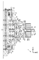
도 1은 본 발명의 일 실시 형태의 쇼트 피닝 장치의 정면도이다.
도 2는 도 1의 쇼트 피닝 장치의 우측면도이다.
도 3은 도 1의 쇼트 피닝 장치의 평면도이다.
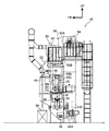
도 4는 도 1의 쇼트 피닝 장치의 세퍼레이터를 도시하는 도면으로, 도 4의 (A)는 도 4의 (B)의 4A-4A선을 따른 단면도이고, 도 4의 (B)는 세퍼레이터의 정면도이다.
도 5는 도 1의 쇼트 피닝 장치에 있어서의 스피너 롤러의 변위 조정 기구를 도시하는 도면으로, 도 5의 (A)는 정면도, 도 5의 (B)는 측면도이다.
도 6은 도 1의 쇼트 피닝 장치에 있어서의 워크의 반송 상태를 도시하는 정면도이다.1 is a front view of a shot pinning apparatus according to an embodiment of the present invention.
Fig. 2 is a right side view of the shot pinning device of Fig. 1;
3 is a plan view of the shot peening apparatus of Fig.
4A is a cross-sectional view taken along the
Fig. 5 is a view showing a displacement adjusting mechanism of the spinning roller in the shot pinning apparatus of Fig. 1, wherein Fig. 5 (A) is a front view and Fig. 5 (B) is a side view.
Fig. 6 is a front view showing the conveying state of the work in the shot peening apparatus of Fig. 1;
도 1∼도 6을 참조하여, 본 발명의 일 실시 형태의 쇼트 처리 장치인 쇼트 피닝 장치에 대해 설명한다. 또한, 이들 도면에 나타나는 화살표 FR은 장치 정면에서 볼 때 전방측을 나타내고 있고, 화살표 UP는 장치 상방측을 나타내고 있고, 화살표 LH는 장치 정면에서 볼 때 좌측을 나타내고 있다.A shot peening apparatus which is a shot processing apparatus according to an embodiment of the present invention will be described with reference to Figs. 1 to 6. Fig. The arrows FR shown in these figures indicate the front side when viewed from the front of the apparatus, the arrows UP indicate the upper side of the apparatus, and the arrows LH indicate the left side viewed from the front of the apparatus.
도 1에는 쇼트 피닝 장치(10)가 정면도에서 도시되고, 도 2에는 쇼트 피닝 장치(10)가 우측면도에서 도시되고, 도 3에는 쇼트 피닝 장치(10)가 평면도에서 도시되어 있다. 본 실시 형태에 관한 쇼트 피닝 장치(10)의 워크(W)는, 코일 스프링 등의 원통형의 제품으로 된다. 또한, 도면 중에 있어서 적절히 나타내어지는 화살표 D는, 워크(W)가 반송되는 반송 방향을 나타내고 있다.Fig. 1 shows the
도 1에 도시되어 있는 바와 같이, 쇼트 피닝 장치(10)는 캐비넷(12)을 구비하고 있다. 캐비넷(12)은 캐비넷(12) 내에서 투사재(쇼트 또는 쇼트재)로서 사용되는 강구가, 쇼트 피닝 장치(10)의 외부에 비산하지 않도록, 쇼트 피닝 장치(10)의 내부 공간과 외부 공간을 구획하는 외벽부를 구비하고 있다. 또한, 장치 하부의 바닥면은, 편평하게 형성, 즉 장치 상하 방향의 높이가 동일해지도록 설정되어 있다.As shown in FIG. 1, the
캐비넷(12)은 워크(W)의 반송 방향의 중간부에 캐비넷 본체(14)를 구비하고 있다. 캐비넷 본체(14)의 내부에는, 투사실(14A)(「투사 부스」,「가공실」,「연소실」이라고도 함)이 형성되어 있다. 투사실(14A)은, 후술하는 투사기(42)에 의해 투사된 투사재에 의해, 워크(W)의 표면 가공(본 실시 형태에서는 피닝 처리)을 실시하는 부스이다.The
캐비넷 본체(14)에는, 워크(W)의 반송 방향의 상류측(도면 중 좌측)에 투사실 입구(14B)가 형성되고, 워크(W)의 반송 방향의 하류측(도면 중 우측)에 투사실 출구(14C)가 형성되어 있다. 투사실 입구(14B)는, 워크(W)를 투사실(14A)에 반입하기 위한 개구이며, 투사실 출구(14C)는, 워크(W)를 투사실(14A)로부터 반출하기 위한 개구이다.The
캐비넷 본체(14)의 워크(W)의 반송 방향의 상류측(도면 중 좌측)에는, 캐비넷(12)의 일부를 구성하는 상류측 부스(16)가 인접하여 배치되어 있다. 상류측 부스(16)는 투사실(14A)에 투사실 입구(14B)에서 연통하는 공간(16A)을 형성하고 있다.An
또한, 상류측 부스(16)에는, 워크(W)를 반입하기 위한 상류측 부스 입구(도시 생략)가 캐비넷 본체(14)의 투사실 입구(14B)에 대향하여 형성되어 있다. 또한, 상류측 부스(16)에 대해 워크(W)의 반송 방향의 더 상류측(도면 중 좌측)에는, 쇼트 피닝 장치(10)에 워크(W)를 세트하기 위해 세트부(15)가 설치되어 있다. 또한, 워크(W)가 무겁거나, 또는 고온이라고 하는 등의 수작업이 곤란해지는 경우에는, 세트부(15)에 매니퓰레이터, 핸들링 장치 등의 반입 장치(도시 생략)를 설치하고, 이 반입 장치로부터 워크(W)를 기계적으로 투입해도 된다.The
한편, 캐비넷 본체(14)의 워크(W)의 반송 방향의 하류측(도면 중 우측)에는, 캐비넷(12)의 일부를 구성하는 하류측 부스(18)가 인접하여 배치되어 있다. 하류측 부스(18)는 투사실(14A)에 투사실 출구(14C)에서 연통하는 공간(18A)을 형성하고 있다.On the other hand, a
또한, 하류측 부스(18)에는, 워크(W)를 반출하기 위한 하류측 부스 출구(도시 생략)가 캐비넷 본체(14)의 투사실 출구(14C)에 대향하여 형성되어 있다.A booth outlet (not shown) on the downstream side for carrying out the work W is formed on the
상류측 부스(16)의 천장부 및 하류측 부스(18)의 천장부로부터는, 투사재의 튀어나옴을 방지하기 위한 워크 반송 방향에 직교하는 방향으로 연장되는 복수의 현수막 형상의 시일체(도시 생략)가 현수되어 있다. 각 시일체는, 워크(W)의 반송 방향으로 소정 간격을 두고, 서로 대략 나란히 배치되어 있다. 이 시일체는, 탄력성 및 가요성을 구비한 복수의 장척재로 구성된 발 형상의 부재(소위, 고무 발)이며, 워크(W)의 통과 시에는, 워크(W)의 반송 방향으로 휘도록 설정되어 있다.A plurality of banner-like sealing bodies (not shown) extending in a direction orthogonal to the workpiece conveying direction for preventing the projection material from protruding are provided from the ceiling portion of the
캐비넷(12)의 내부에는, 워크(W)를 연속적으로 반송하기 위한 체인 컨베이어(20)가 설치되어 있다. 이 체인 컨베이어(20)는 무단의 체인(22)을 구비하고 있다. 체인(22)은 반입측에 배치된 스프로킷(24)과 반출측에 배치된 스프로킷(24)에 권회되어 있다. 스프로킷(24)은 모터 등의 구동원(25)에 연결되어 회전 구동된다.Inside the
도 6은 체인 컨베이어(20)에 의한 워크(W)의 반송 상태를 도시하는 정면도이다. 또한, 도면 중 전방측의 후술하는 스피너 롤러(28)는 도 5에서는 생략되어 있다. 도 6에 도시되어 있는 바와 같이, 체인(22)의 외주면에는, 워크(W)를 지지하는 복수의 캐리어(26)가 설치되어 있다. 캐리어(26)는 본체 부분이 막대 형상으로 되고, 체인(22)의 길이 방향을 따라 등간격으로 배치되고, 체인(22)의 주회 시에 워크(W)의 단부를 반송 방향 상류측으로부터 지지하고, 워크(W)를 연속적으로 이송하도록 되어 있다. 도 5의 (B)에 도시된 바와 같이, 체인(22)은 좌우로 쌍을 이루어 설치되어 있고, 캐리어(26)는 좌우 한 쌍의 체인(22)에 걸쳐진 체인 플레이트(23) 상에 수직으로 세워 설치되어 있다.Fig. 6 is a front view showing the conveying state of the work W by the
체인(22)의 상방측에서, 또한 캐리어(26)의 양쪽 사이드에는, 자전 롤러에 의해 구성된 한 쌍의 스피너 롤러(28)가 배치되어 있다. 한 쌍의 스피너 롤러(28)는 워크(W)의 반송 방향의 양측에 배치되고, 한 쌍의 스피너 롤러(28) 상에 워크(W)가 적재된다. 또한, 이들 체인 컨베이어(20) 및 스피너 롤러(28)에 의해 워크(W)를 반송하는 반송 수단이 구성된다.On the upper side of the
한 쌍의 스피너 롤러(28)의 축부에는, 스피너 롤러(28) 사이의 거리를 변경 조정하는 변경 조정 기구(30)가 설치되어 있다. 변경 조정 기구(30)는 캐리어(26)의 양쪽 사이드에 배치된 한 쌍의 회전 아암(30A)을 구비하고 있고, 회전 아암(30A)의 선단부는, 한 쌍의 스피너 롤러(28)의 중심축을, 회전 가능하게 지지하고 있다. 각 회전 아암(30A)의 기단부는, 캐리어(26)의 근접 위치에 배치되고, 회전축(30B)에 각각 고정되어 있다.A change adjusting mechanism (30) for adjusting the distance between the spinner rollers (28) is provided at the shaft portion of the pair of spinner rollers (28). The
도 5의 (A)에 도시된 바와 같이, 회전축(30B)은, 장치 프레임측에 회전 가능하게 지지됨과 함께, 무단 벨트(30C)를 통해 구동원인 구동 모터(30D)의 축부측에 접속되어 있다. 즉, 변경 조정 기구(30)는 구동 모터(30D)의 회전에 따라 회전축(30B)이 회전함으로써, 회전 아암(30A)이 피봇 이동하고, 도 5의 (B)에 도시된 바와 같이, 스피너 롤러(28)의 축부를 원호 궤도를 따라 변위시키도록 되어 있다.As shown in Fig. 5A, the
본 실시 형태의 구성에서는, 큰 워크(W)를 한 쌍의 스피너 롤러(28)에 적재하는 경우에, 한 쌍의 스피너 롤러(28)의 축부를 서로 이격시키도록 원호 형상으로 변위시키면, 한 쌍의 스피너 롤러(28)의 높이 위치를 낮출 수 있다. 이로 인해, 본 실시 형태의 변경 조정 기구(30)를 구비한 장치에서는, 예를 들어 한 쌍의 스피너 롤러(28)의 축부를 상호의 접근 위치와 이격 위치 사이에서 수평 이동시키는 다른 변경 조정 기구를 구비한 장치에 비해, 큰 워크(W)의 상단부 높이 위치가 낮게 억제되므로, 캐리어(26)의 길이를 억제할 수 있고, 이 결과, 장치 전체의 높이를 억제하는 것이 가능하게 되어 있다.In the structure of this embodiment, when a large work W is loaded on a pair of
또한, 도 5의 (A)에 도시된 바와 같이, 회전 아암(30A)의 선단부에는, 구동 모터(29)가 브래킷(31)을 통해 고정되어 있고, 구동 모터(29)의 출력축이 스피너 롤러(28)의 축부에 연결되어 있다. 이에 의해, 스피너 롤러(28)는 중심축을 중심으로 하여 회전 구동 가능하게 되어 있다. 도 5의 (B)에 도시되는 한 쌍의 스피너 롤러(28)는 중심축을 중심으로 하여, 동일 방향으로 회전 구동되도록 되어 있다. 또한, 한 쌍의 스피너 롤러(28)는 동일 직경이며, 또한 동일한 일정 속도로 회전되는 것이 바람직하다.5A, a
또한, 안정된 피닝 효과를 얻기 위해서는, 워크(W)의 위치 제어가 중요하다. 워크(W)의 위치 제어를 정확하게 행하기 위해서는, 스피너 롤러(28)의 자전 기구 및 워크(W)의 반송 기구가 정확하게 작동할 필요가 있다.In addition, in order to obtain a stable pinning effect, position control of the work W is important. In order to precisely control the position of the work W, the spinning mechanism of the spinning
스피너 롤러(28)의 자전 기구에서는, 마무리 품질에 맞춘 롤러 회전수를 설정하기 위해 자전 롤러 인버터를 장비하고, 및 안정된 제품 반송용으로서 고정밀도·고수명 부품을 사용하는 것이 바람직하다. 자전 롤러 인버터를 장비함으로써, 마무리 품질에 따른 롤러 회전수의 설정 변경이 가능(용이)하게 되고, 반송 속도와 링크한 제어도 가능하게 된다. 또한, 스피너 롤러(28)에 고정밀도·고수명 부품을 사용함으로써 조기 편마모에 의한 반송 불량이 방지, 또는 효과적으로 억제되어, 최소의 단차로 걸림이 적어진다.In the rotating mechanism of the
또한, 워크(W)의 반송 기구는, 안정된 제품 반송을 위해 체인(22)에 특수 체인을 사용하고, 및 마무리 품질에 맞춘 반송 속도를 설정하기 위해 인버터를 장비하는 것이 바람직하다.It is preferable that the transport mechanism of the workpiece W be equipped with an inverter to use a special chain for the
특수 체인으로서는, 투사재(쇼트)의 물려 들어감을 억제하기 위해, 클리어런스가 있어 내마모성을 갖는 것이 사용된다. 이와 같은 특수 체인을 사용함으로써 워크(W)의 반송 기구의 수명이 연장되어 반송 트러블도 방지 또는 효과적으로 억제할 수 있다. 또한, 인버터를 장비함으로써, 마무리 품질에 따른 반송 속도의 설정 변경이 가능(용이)하게 되고, 자전 회전수와 링크한 제어도 가능하게 된다.As the special chain, a material having a clearance and abrasion resistance is used in order to suppress the entrapment of the projection material (shot). By using such a special chain, the service life of the transport mechanism of the work W is prolonged, and the transport trouble can also be prevented or effectively suppressed. Further, by equipping the inverter, the setting of the conveying speed can be changed (facilitated) in accordance with the finishing quality, and the control linked to the rotation speed can be also performed.
도 1에 도시된 바와 같이, 캐비넷(12)의 워크(W)의 반송 방향 최하류측에는, 반출 슈트(32)가 설치되어 있다. 반출 슈트(32)는, 그 상단부가, 스피너 롤러(28)의 연장선상에 배치되고, 캐비넷(12)측으로부터 이격되는 방향에 있어서 하방을 향하여 경사져 있다. 즉, 반출 슈트(32)는, 스피너 롤러(28)에 적재되어 체인 컨베이어(20)의 캐리어(26)(도 6 참조)에 의해 이송되어 온 워크(W)를, 캐비넷(12) 외부로 안내하는 부재이다.As shown in Fig. 1, a take-out
캐비넷 본체(14) 내의, 워크(W)의 반송 통로의 상방측에 복수대(본 실시 형태에서는 일례로서 총 2대)의 투사기(42)가 설치되어 있다. 투사기(42)는 공지의 구조를 갖는 원심식 투사기이며, 복수의 블레이드를 구비한 임펠러의 회전에 의해, 컨트롤 케이지 내의 투사재(쇼트)에 원심력을 부여하고, 컨트롤 케이지의 개구 창을 통하여 투사재를 방출한다.A plurality of projectors 42 (two projectors in this embodiment, for example) are provided above the conveying path of the work W in the
즉, 투사기(42)는 투사재를 원심력으로 가속하여, 투사실(14A)에 반송된 워크(W)를 향해 연직 하방으로 또는 경사 하방으로 투사하도록 되어 있다. 또한, 본 실시 형태에서는, 투사기(42)가 복수대 배치되어 있지만, 본 발명은 투사기(42)가 1대인 구성이어도 된다.That is, the
여기서, 안정된 피닝 효과를 얻기 위해 중요해지는 쇼트 투사 관리에 대해 보충 설명한다. 또한, 안정된 피닝 효과를 얻기 위해서는, 쇼트 입도 관리도 중요해지지만, 이 점에 대해서는 후술한다.Here, the shot projection management, which becomes important for obtaining a stable pinning effect, will be supplemented. Further, in order to obtain a stable pinning effect, short particle size control is also important, but this point will be described later.
쇼트 투사 관리에 있어서는, 쇼트 유량, 임펠러 회전수 및 투사 패턴이 중요 항목으로 된다.In the shot projection management, the shot flow rate, the number of impeller rotations, and the projection pattern become important items.
쇼트 유량에 대해서는, 적정량의 투사재를 안정적으로 투사하기 위해, 쇼트 탱크 레벨계 및 하한 검지 기능이 있는 임펠러 전류계를 설치하는 것이 바람직하다. 쇼트 탱크 레벨계는, 후술하는 투사재 호퍼(48)에 설치되고, 쇼트 보급 타이밍을 하는 계량기이다.As for the short flow rate, it is desirable to provide a short tank level meter and an impeller ammeter having a lower limit detection function in order to stably project an appropriate amount of the projection material. The short tank level meter is a meter installed at the projection re
하한 검지 기능이 있는 임펠러 전류계는, 투사량 부족을 검지하고, 투사 부족의 경우에는, 이상 표시를 행하고, 또한 장치를 정지시켜, 처리가 불충분한 불량품이 장치로부터 유출되는 것을 방지하기 위한 장치이다.An impeller ammeter having a lower limit detecting function is a device for detecting the insufficient amount of projection, performing an abnormality display in the case of insufficient projection, and stopping the apparatus to prevent defective products, which are insufficiently processed, from flowing out of the apparatus.
임펠러 회전수에 대해서는, 마무리 품질에 맞춘 적정 투사 속도의 설정 및 그 상태의 유지를 이루기 위해, 임펠러에의 구동력 전달용으로 된 V벨트의 상태(마모나 연신)의 점검 및 임펠러 인버터의 장비가 바람직하다. 임펠러 인버터를 사용함으로써, 마무리 품질에 따른 임펠러 회전수의 설정 변경이 가능(용이)하게 된다.As for the impeller rotation speed, it is desirable to check the state of the V-belt (abrasion and elongation) for the transmission of the driving force to the impeller and the equipment of the impeller inverter in order to set and maintain the proper projection speed in accordance with the finishing quality Do. By using the impeller inverter, the setting of the number of revolutions of the impeller according to the finishing quality can be changed (facilitated).
투사 패턴에 대해서는, 워크에 대해 적정한 투사 위치에서 투사재를 투사하기 위해, 컨트롤 케이지 각도의 표시(화살표 명판으로 기준 위치 표시) 및 임펠러 관계의 소모품(블레이드, 컨트롤 케이지, 디스트리뷰터 등)에 관한 교환 시기를 알리는 기능을 마련하는 것이 바람직하다. 후자에 대해서는, 임펠러 관계 부품의 마모에 의해 투사 위치·투사량이 변화되는 것을 방지하기 위해서이다.With respect to the projection pattern, the switching timing of the control cage angle display (reference position display by the arrow nameplate) and the impeller-related consumables (blade, control cage, distributor, etc.) for projecting the projection material at the proper projection position for the workpiece It is desirable to provide a function of notifying the user of the information. The latter is to prevent the projection position and projection amount from being changed by wear of the impeller related parts.
각 투사기(42)의 상방측에는, 투사재 도입 파이프(44)(「도입관」이라고도 함)가 배치되어 있다. 투사재 도입 파이프(44)의 상단부는, 커트 게이트(46)(유량 조정 장치)를 통해 투사재 호퍼(48)(쇼트 탱크)에 접속되어 있다. 투사재 호퍼(48)는 투사재를 일시적으로 저류하기 위한 호퍼이다. 본 실시 형태의 투사재 호퍼(48)의 내부 공간인 메인부(48A)는, 워크 반송 방향의 상류 및 하류측이 구획벽(48D)으로 구획되고, 워크 반송 방향에 직교하는 방향의 양측이 사이드부(48B, 48C)에 의해 구획되어 있다.A projection material introducing pipe 44 (also referred to as an " introducing tube ") is disposed above each of the
투사재 호퍼(48)의 메인부(48A)의 바닥부측에, 전술한 커트 게이트(46)가 접속되어 있다. 또한, 커트 게이트(46)는 투사재 호퍼(48)의 메인부(48A)로부터 공급되는 투사재의 유량을 조정하기 위한 개폐 게이트이다.The
투사재 호퍼(48)의 좌측의 사이드부(48B)의 바닥부측에는, 공급 파이프(34A)를 통해 제1 쇼트 커튼 장치(36)가 접속되어 있다. 제1 쇼트 커튼 장치(36)는 투사실 입구(14B)의 상방측에 배치되고 캐비넷(12)에 고정되어 있다. 제1 쇼트 커튼 장치(36)는 공급 파이프(34A)에 접속된 용기부(36A)를 구비함과 함께, 용기부(36A)의 바닥부에 접속된 하향의 직사각형 파이프(36B)를 구비하고 있다. 직사각형 파이프(36B)는, 직사각형 통 형상으로 형성되고, 투사재를 유출시키기 위해 사용된다.A first
용기부(36A)는, 내부 공간이, 상부 구획판에 의해 상부 공간과 그 하방측 공간으로 구획되어 있다. 그리고, 제1 쇼트 커튼 장치(36)에는, 상부 구획판의 개구부를 개폐 가능한 게이트 기구(36D)가 설치되어 있다. 또한, 용기부(36A)의 내부의 상부 구획판의 개구부의 하방측에는, 상방을 향하여 개방되는 상자 형상의 수용부가 설치되고, 수용부는, 상부 구획판의 개구부를 통하여 낙하하는 투사재를 일단 수용한 후에 하방측으로 공급하도록 구성되어 있다.In the
이와 같이 구성된 제1 쇼트 커튼 장치(36)는 공급 파이프(34A)로부터 공급된 투사재를, 용기부(36A) 경유로 직사각형 파이프(36B)를 통하여, 투사실 입구(14B)의 상부로부터 연속적으로 커튼 형상으로 낙하시켜, 소위 쇼트 커튼을 생성하는 것이 가능하게 된다. 즉, 투사실 입구(14B)는, 게이트 기구(36D)의 게이트 개폐에 의해, 쇼트 커튼이 개폐되는 구조를 구비하고 있다.The first
또한, 투사재 호퍼(48)의 우측의 사이드부(48C)에 있어서의 바닥부측에는, 공급 파이프(34B)를 통해 제2 쇼트 커튼 장치(38)가 접속되어 있다. 제2 쇼트 커튼 장치(38)는 투사실 출구(14C)의 상방측에 배치되고 캐비넷(12)에 고정되어 있다. 제2 쇼트 커튼 장치(38)는 공급 파이프(34B)에 접속되는 용기부(38A)를 구비하고, 용기부(38A)의 바닥부에 접속된 하향의 직사각형 파이프(38B)를 구비하고 있다. 직사각형 파이프(38B)는, 직사각형 통 형상으로 형성되어 있고, 투사재의 유출용으로 되어 있다.A second
용기부(38A)는, 그 내부 공간이 상부 구획판에 의해 상부 공간과 그 하방측 공간으로 구획되어 있다. 그리고, 제2 쇼트 커튼 장치(38)에는, 상부 구획판의 개구부를 개폐 가능한 게이트 기구(38D)가 설치되어 있다. 또한, 용기부(38A)의 내부에 있어서, 상부 구획판의 개구부의 하방측에는, 상방을 향하여 개방되는 상자 형상의 수용부가 설치되고, 수용부는, 상부 구획판의 개구부를 통하여 낙하하는 투사재를 일단 수용한 후에 하방측으로 공급하도록 되어 있다.The inner space of the
이와 같이 구성된 제2 쇼트 커튼 장치(38)는 공급 파이프(34B)로부터 공급된 투사재를, 용기부(38A) 경유로 직사각형 파이프(38B)를 통하여 투사실 출구(14C)의 상부로부터 연속적으로 커튼 형상으로 낙하시켜, 소위 쇼트 커튼을 생성하는 것이 가능하게 되어 있다. 즉, 투사실 출구(14C)는, 게이트 기구(38D)의 게이트 개폐에 의해 쇼트 커튼이 개폐되는 구조를 구비하고 있다.The second
또한, 캐비넷(12) 상에 있어서 제1 쇼트 커튼 장치(36)와 제2 쇼트 커튼 장치(38) 사이에 배치된 투사기(42)는 투사재 도입 파이프(44), 커트 게이트(46) 및 투사재 호퍼(48)의 메인부(48A)를 통해 순환 장치(50)에 연결되어 있다. 순환 장치(50)는 투사기(42)에 의해 투사된 투사재를 반송하여 투사기(42)로 순환시키기 위한 장치이며, 캐비넷(12)의 내부에 있어서의 체인 컨베이어(20)의 하방측에 하부 스크루 컨베이어(52)를 구비하고 있다.The
하부 스크루 컨베이어(52)가 워크(W)의 반송 방향을 길이 방향으로 하여 수평하게 배치되어 있다. 하부 스크루 컨베이어(52)의 스크루 블레이드의 나선 권취 방향은, 쇼트 피닝 장치(10)의 반송 방향 상류측에 배치되는 부위와 쇼트 피닝 장치(10)의 반송 방향 하류측에 배치되는 부위에서 역방향으로 되어 있다. 이 결과, 하부 스크루 컨베이어(52)는 축을 중심으로 회전함으로써, 투사된 투사재 등을 쇼트 피닝 장치(10)의 반송 방향 상류 및 하류측으로부터 중앙부측으로 반송하고, 투사재 등을 1개소에서 회수할 수 있도록 하고 있다.And the
하부 스크루 컨베이어(52)의 쇼트 피닝 장치(10)의 반송 방향 중앙부는, 투사재의 회수 경로가 배치된 버킷 엘리베이터(54)(도 2)의 하부 수집부에 인접하여 배치되어 있다. 그리고, 버킷 엘리베이터(54)는 하부 스크루 컨베이어(52)에 의해 쇼트 피닝 장치(10)의 반송 방향 상류 및 하류측으로부터 중앙부측으로 반송되어 온 투사재 등을 하부 스크루 컨베이어(52)로부터 수용하게 된다.The central portion in the conveying direction of the
버킷 엘리베이터(54)는 공지의 구조이기 때문에 상세한 설명을 생략하지만, 쇼트 피닝 장치(10)의 상부 및 하부에 배치된 풀리(54A)에 무단 벨트(54B)가 권회되고, 이 무단 벨트(54B)에 다수의 버킷(도시 생략)이 설치된 구조를 갖고 있다.The
풀리(54A)는, 모터에 의해 회전 구동된다. 이 회전 구동에 의해, 버킷 엘리베이터(54)는 쇼트 피닝 장치(10)의 하부에 낙하하여 하부 스크루 컨베이어(52)에서 회수된 투사재 등[워크(W)에 투사된 투사재와 분립상의 이물질을 포함하는 혼합물]을 버킷으로 퍼올리고, 쇼트 피닝 장치(10)의 하부로부터 상부[캐비넷(12)의 상방측]로 반송하도록 되어 있다.The
본 실시 형태에서는, 하부 스크루 컨베이어(52), 버킷 엘리베이터(54) 등에 의해, 투사재의 회수 기구가 구성되어 있다.In the present embodiment, the
버킷 엘리베이터(54)의 상단부의 장치 전방측에는, 분배 상자(56)가 인접하여 배치되어 있고, 버킷 엘리베이터(54)의 상부 반출구(투출구부)를 통해 분배 상자(56)에 연통 접속되어 있다.A distributing
도 1 및 도 2에 도시된 바와 같이, 분배 상자(56)는 버킷 엘리베이터(54)의 버킷으로부터 투사된 투사재를, 투사기(42)에 공급하기 위한 제1 루트(40A)와, 제1 쇼트 커튼 장치(36)에 공급하기 위한 제2 루트(40B)와, 제2 쇼트 커튼 장치(38)에 공급하기 위한 제3 루트(40C)에 분배한다.1 and 2, the
제1 루트(40A)는, 투사재가, 분배 상자(56)로부터 세퍼레이터(60), 투사재 호퍼(48)의 메인부(48A), 커트 게이트(46) 및 투사재 도입 파이프(44)를 통하여 투사기(42)에 이르는 루트이다.The
또한, 도 1에 도시되어 있는 제2 루트(40B)는, 투사재가, 분배 상자(56)로부터 분배 파이프(58A), 투사재 호퍼(48)의 좌측의 사이드부(48B) 및 공급 파이프(34A)를 통하여 제1 쇼트 커튼 장치(36)에 이르는 루트이다.The
또한, 제3 루트(40C)는, 투사재가 분배 상자(56)로부터 분배 파이프(58B), 투사재 호퍼(48)의 우측의 사이드부(48C) 및 공급 파이프(34B)를 통하여 제2 쇼트 커튼 장치(38)에 이르는 루트이다.The
도 2에 도시된 바와 같이, 버킷 엘리베이터(54)의 상부 배출측은, 분배 상자(56)를 통해 세퍼레이터(60)[풍력 선별 기구(62)]에 접속됨과 함께, 분배 상자(56)를 통하거나, 또한 세퍼레이터(60)[풍력 선별 기구(62)]를 통하지 않고 제1 쇼트 커튼 장치(36)(도 1 참조) 및 제2 쇼트 커튼 장치(38)에 접속되어 있다.2, the upper discharge side of the
도 4에는, 풍력 선별 기구(62)를 구비한 세퍼레이터(60)(대향식 분급 장치)의 구성이 도시되어 있다. 도 4의 (A)는 세퍼레이터(60)의 측단면도[도 4의 (B)의 4A-4A선을 따른 단면도]이며, 도 4의 (B)는 세퍼레이터(60)의 정면도이다. 또한, 이하의 도 4의 설명에 있어서는, 장치 좌우 방향과 동일한 방향을 세퍼레이터 폭 방향이라고 한다.Fig. 4 shows the structure of the separator 60 (counterclockwise classification device) provided with the wind
세퍼레이터(60)는 워크(W)에 투사된 투사재를 회수하기 위한 회수 경로에 설치되고, 도 4의 (A)에 도시된 바와 같이, 집진기(80)의 흡기측에 통하는 세틀링 챔버부(68)를 구비하고 있다. 세틀링 챔버부(68)의 상측부에는 덕트 접속용의 플랜지(68B)[도 4의 (B) 참조]가 형성되어 있다.The
또한, 집진기(80)는 투사재에 혼입된 미분 등의 이물질(불순물)을 회수하기 위한 것이고, 공기를 흡입하는 흡입 장치(블로워)를 구비하고, 흡인 덕트(70)(세퍼레이터 덕트)를 통해 세틀링 챔버부(68)에 접속되어 있다. 세틀링 챔버부(68)의 기류 상류측에는, 대향 풍선부(66)가 설치되어 있다. 또한, 대향 풍선부(66)의 세틀링 챔버부(68)측과 반대측의 측방에는, 버킷 엘리베이터(54)의 상부 반출구로부터 반출된 투사재 등을 대향 풍선부(66)로 공급하기 위한 공급부(64)가 설치되어 있다.The
공급부(64)에는, 공급부(64)를 상하 2개의 공간으로 구분하는 메쉬 형상의 스크린(64A)이 수평하게 설치되어 있다. 스크린(64A)의 그물코의 성김은, 투사재가 통과 가능한 사이즈로 설정되어 있다. 공급부(64)의 스크린(64A)보다도 하방측에, 경사부(64B)가 형성되어 있다. 경사부(64B)는, 대향 풍선부(66)의 유로 상류측에 형성되고, 하방측을 향해 대향 풍선부(66)측(즉, 경사 하방)으로 경사져, 대향 풍선부(66)[자유 낙하 존(66B)]에 공급되는 투사재와 이물질의 혼합물이 유동하도록 흘러내리는 영역으로 되어 있다.In the
또한, 공급부(64)의 최하류부에는, 대향 풍선부(66)와의 연통 개구부(65)의 상부측을 덮도록 배치된 규제판(64C)이 설치되어 있다. 규제판(64C)은, 세퍼레이터 폭 방향[도 4의 (A)의 지면(紙面)에 수직한 방향]으로 연장되는 판체이다. 규제판(64C)은, 그 상단부가 연통 개구부(65)의 상방측에 있어서 공급부(64)와 대향 풍선부(66)의 격벽에 고정됨으로써, 하방으로 현수되고, 규제판(64C)의 하측 단부 테두리와 경사부(64B)의 하류 단부 사이에 세퍼레이터 폭 방향으로 연장되는 가늘고 긴 간극을 형성하도록 배치되어 있다. 이 간극을 통하여, 투사재와 이물질의 혼합물이 유출된다. 또한, 규제판(64C)의 높이 위치는, 조정 가능하게 되어 있다.A restricting
경사부(64B)는, 혼합물을 자유 낙하시키는 자유 낙하 존(66B)의 유로 상류측에 설치되고, 규제판(64C)은, 공급부(64)로부터 대향 풍선부(66)로 유출되는 분립물(투사재를 포함하는 혼합물)의 층을 세퍼레이터 폭 방향[도 4의 (A)의 지면에 수직한 방향]으로 충분히 확산하여 균일하게 하는 기능을 갖는다.The
대향 풍선부(66)는 통 형상으로 형성되고 쇼트 피닝 장치(10)의 상하 방향으로 연장되는 주위벽부(66A)를 구비하고 있다. 주위벽부(66A)는, 그 내측이 공기 통로로 되고, 길이 방향 중간부에, 규제판(64C)의 하측 단부 테두리와 경사부(64B)의 하류 단부 사이에 형성된 간극이 공급부(64)와의 연통구로서 개방되어 있다.The
주위벽부(66A)에 있어서 공급부(64)와의 연통부보다도 하방측의 부위의 내측 공간은, 혼합물을 자유 낙하시키기 위한 자유 낙하 존(66B)으로 되어 있다.The inner space of a portion of the
주위벽부(66A)의 하단부 개구부(66C)는, 하향으로 개방된 에어 도입구로 되고, 그 외주측에는, 도시하지 않은 메쉬 형상의 스크린이 수평하게 쳐져 있다. 이로 인해, 자유 낙하 존(66B)에서는, 집진기(80)가 작동하면, 스크린을 통과한 외기가 주위벽부(66A)의 하단부 개구부(66C)로부터 유입되어 주위벽부(66A)를 통하는 상향의 기류(f1)가 발생한다.The lower
주위벽부(66A)의 하부에는, 복수의 분산 막대(66D)가 자유 낙하 존(66B)을 가로지르도록 설치되어 있다. 분산 막대(66D)는, 각기둥 또는 원기둥 형상을 갖고, 간격을 두고 경사부(64B)의 연장선상에 경사부(64B)로부터 이격됨에 따라 하방에 위치하도록 배치되어 있다. 분산 막대(66D)는, 자유 낙하 존(66B) 내를 자유 낙하하는 투사재와 이물질의 혼합물을, 자유 낙하 존(66B) 내에서 분산시키도록 구성되어 있다. 그리고, 자유 낙하하는 투사재와 이물질의 혼합물이, 분산 막대(66D)에 의해 분산됨으로써, 낙하하는 혼합물의 사이에 적당한 공간이 생겨, 자유 낙하 존(66B) 내의 상향의 기류(f1)가, 낙하하는 혼합물의 사이에 대략 균일하게 흐른다. 이 결과, 상향의 기류는, 자유 낙하하는 투사재와 이물질의 사이에서 대략 균일하게 흘러, 상향의 기류에 의한 혼합물의 선별(분급)이 용이하게 되어 있다.In the lower portion of the
분산 막대의 간격은, 분산 막대 상에서 투사재가 체류되지 않아, 기류(f1)를 방해하지 않는 넓이이며, 또한 자유 낙하하는 투사재와 이물질을 불균일없이 분산시킬 수 있는 간격으로 설정되어 있다.The interval of the dispersion bars is set so that the projection material does not stagnate on the dispersion bar and does not interfere with the air flow f1 and is spaced apart so as to disperse the freely falling projected material and foreign matter unevenly.
풍력 선별 기구(62)의 자유 낙하 존(66B)의 하방측에는, 주위벽부(66A)의 하단부 개구부(66C)의 대향 위치에 오목 형상(접시 형상)의 수용부(72)가 설치되어 있다. 수용부(72)는 투사재에 의한 부품의 마모 방지용으로 되고, 자유 낙하하는 투사재를 일단 수용하여, 낙하를 정지시킨 후에, 그 하방측의 투사재 호퍼(48)의 메인부(48A)(도 1 참조)로 공급하도록 되어 있다.A receiving
이상과 같은 구성에 의해, 대향 풍선부(66)에서는, 상향의 기류(f1)를 닿게 하면서 투사재와 분립상의 이물질의 혼합물을 자유 낙하시킴으로써, 기류(f1)를 타는 경량물을, 낙하하는(화살표 S1 방향 참조) 중량물로부터 분리한다.With the above-described configuration, in the opposing
보다 구체적으로는, 대향 풍선부(66)는 기류(f1)를 타는 「입경이 작고 가벼운 것」(이물질)과 낙하하는 「입경이 크고 무거운 것」(투사재)을 선별하고 있다.More specifically, the opposing
세틀링 챔버부(68)의 상부에는, 안내판(68A)이 상벽측으로부터 현수되도록 배치되어 있다. 안내판(68A)은, 집진기(80)의 흡입력에 의해 세틀링 챔버부(68)의 내부에 흡입된 분립물을 포함하는 공기를 안내하고, 그 공기에 분급류로서의 우회류(f2)를 발생시키도록 되어 있다.On the upper portion of the settling
즉, 세틀링 챔버부(68)는 흡입된 공기 중의 입자를 우회류(f2)에 의해 분리(선별)하도록 되어 있다. 보다 구체적으로는, 세틀링 챔버부(68)는 흡입된 분립물(이물질) 중, 보다 입경이 작고 가벼운 미분(분상물) 등을 기류에 타게 하여 집진기(80)측으로 배출하고(화살표 S3), 보다 입경이 크고 무거운 미분(입상물) 등을 낙하시키고(화살표 S2), 도 2에 도시되는 조출 파이프(82)를 통해 조출 케이스(84)측으로 배출하도록 되어 있다.That is, the settling
안정된 피닝 효과를 얻기 위해서는, 쇼트 입도 관리가 중요하고, 분급 장치[세퍼레이터(60)]의 구성 및 집진 풍량의 관리가 포인트로 된다. 분급 장치에 대해서는, 쇼트 입도의 유지를 위해, 전술한 바와 같이, 대향식 분급 장치를 채용하고 있다. 이와 같은 대향식 분급 장치를 사용함으로써, 직향식 분급 장치에 비해 보다 정밀도가 좋은(미세한) 입도 관리가 가능하게 된다. 또한, 집진 풍량의 관리에 대해서는, 분급 장치의 성능을 유지하기 위해, 차압 상한 스위치를 집진기(80)[도 3 및 도 4의 (A) 참조] 등에 설치하고, 이에 의해 차압 상한 검지 기능을 갖게 하여, 필요 풍량 이하로 된 경우에는 이상 표시를 하게 하는 것이 바람직하다.In order to obtain a stable pinning effect, short particle size management is important, and the construction of the classification device (separator 60) and the management of the dust volume are important points. For the classification apparatus, as described above, an opposite classifier is employed for maintaining the short particle size. By using the above-described counterclockwise classification apparatus, granularity management with finer (finer) granulation can be achieved compared with the direct type classifier. In order to maintain the performance of the classification apparatus, the upper limit switch for differential pressure is installed in the dust collector 80 (see Figs. 3 and 4 (A)) or the like to manage the collection air volume, If the air flow rate is less than the required air flow rate, it is preferable to display an anomaly.
또한, 쇼트 피닝 장치(10)에 있어서, 안정된 피닝 효과를 얻기 위해서는, 소모품 관리도 중요해지고, 예방 보전을 위해 교환 시기를 표시하는 것이 포인트로 된다. 이로 인해, 예를 들어 도 3에 도시되는 제어반(90A) 등에 소모품 통지 기능을 마련하여 터치 패널에서 소모품의 교환 시기를 표시하고, 또한, 제어반(90A) 등에 소모품 교환 이력을 표시하여 소모품의 교환 주기를 파악할 수 있도록 하는 것이 바람직하다.In addition, in order to obtain a stable pinning effect in the
쇼트 피닝 장치(10)를 구성하는 소모품으로서는, 도 1∼도 3에 도시되는 투사기(42)를 구성하는 각 소모품, 워크(W)를 반송하기 위한 반송 기구를 구성하는 각 소모품, 순환 장치(50)를 구성하는 각 소모품 및 투사실(14A) 내의 보호 라이너에 관련하는 각 소모품 등이 있다.The consumables constituting the
투사기(42)를 구성하는 각 소모품에는, 예를 들어 블레이드, 컨트롤 케이지, 디스트리뷰터 및 라이너 관계의 부품이 있다. 워크(W)를 반송하기 위한 반송 기구를 구성하는 각 소모품에는, 예를 들어 스피너 롤러(28), 체인(22), 캐리어(26) 및 반송 가이드가 있다. 순환 장치(50)를 구성하는 각 소모품에는, 예를 들어 하부 스크루 컨베이어(52), 버킷 엘리베이터(54)의 무단 벨트(54B) 및 버킷 엘리베이터(54)의 버킷이 있다.Each consumable constituting the
도 3에 도시된 바와 같이, 본 실시 형태에서는, 제어반(90A)을 구비한 제어 장치(90)는 계산부(92)를 구비하고 있다. 계산부(92)는 컴퓨터 등에 의해 구성되고, 쇼트 피닝 장치(10)를 구성하는 각 소모품에 대해, 그 가동 시간 tx(소모 시간)와, 미리 설정된 수명 시간 tz를 비교하여, 각 소모품의 교환 시기를 계산한다. 여기서, 가동 시간 tx는, 투사기(42)의 투사 시간과 동등한 시간으로서 계측되어 있고, 시퀀서 제어에 의해 적산되어 있다. 그리고, 제어반(90A)에는, 표시부(94)(디스플레이)가 설치되어 있고, 표시부(94)는 계산부(92)의 계산 결과를 표시 가능하게 되어 있다.As shown in Fig. 3, in the present embodiment, the
제어 장치(90)는 제어반(90A)의 조작 등에 따라, 계산부(92)의 계산 결과의 전부 또는 일부를 표시부(94)에 표시시킨다. 후자의 예(일부 표시)에서는, 제어 장치(90)는 표시 대상을 특정하기 위한 판정부(도시 생략)를 구비해도 된다. 판정부는, 예를 들어 쇼트 피닝 장치(10)를 구성하는 각 소모품에 대해, 그 가동 시간 tx와, 수명 시간 tz보다도 짧게 미리 설정된 표준 시간 ta를 비교하여, 가동 시간 tx가 표준 시간 ta를 상회하는지의 여부를 판정한다. 그리고, 제어 장치(90)는 판정부에 의해 가동 시간 tx가 표준 시간 ta를 상회한다고 판정된 소모품에 대해서만, 그 교환 시기를 표시부(94)에 있어서 표시하도록 제어한다.The
또한, 제어 장치(90)는 기억부(96)를 구비하고 있다. 기억부(96)에는, 쇼트 피닝 장치(10)를 구성하는 각 소모품에 관한 교환 이력의 정보가, 예를 들어 제어반(90A)으로부터 작업자에 의해, 입력되도록 되어 있다. 그리고, 기억부(96)는 쇼트 피닝 장치(10)를 구성하는 각 소모품에 관한 교환 이력의 정보를 기억한다. 한편, 표시부(94)는 기억부(96)에서 기억된 교환 이력의 정보를 표시 가능하게 되어 있다. 즉, 예를 들어 제어반(90A)에서 상기 교환 이력의 정보의 표시를 요구하는 조작이 이루어진 경우, 표시부(94)에는, 교환 이력의 정보가 표시된다.The
기억부(96)는 과거에 발생한 동작 이상 이력의 정보를 기억하는 것이어도 되고, 표시부(94)는 기억부(96)에서 기억된 동작 이상 이력의 정보를 표시 가능한 것으로 해도 된다. 이와 같은 동작 이상 이력의 표시 기능을 가짐으로써, 동작 이상의 발생의 빈도나 경향이 파악되기 쉬워져, 중대 트러블이 미연에 방지된다. 또한, 동작 이상의 원인 해명 시에는, 동작 이상의 발생 이력으로부터 동작 이상의 원인이 어느 정도 추측 가능하게 된다. 따라서, 동작 이상 이력의 표시 기능을 갖는 것은, 동작 이상 상태로부터의 조기 복귀에도 도움이 된다.The
이어서, 상기 실시 형태의 쇼트 피닝 장치(10)의 동작에 대해 설명한다.Next, the operation of the
본 실시 형태에 관한 쇼트 피닝 장치(10)에서는, 도 1에 도시되는 워크(W)에 대해 투사기(42)가 투사재를 투사한다. 본 실시 형태에서는, 코일 스프링 등의 원통 형상의 워크가 처리된다.In the
워크(W)에 투사된 투사재를 회수하기 위한 회수 경로에는, 도 4에 도시되는 풍력 선별 기구(62)가 설치되어 있고, 이 풍력 선별 기구(62)는 투사재와 분립상의 이물질을 포함하는 혼합물을 자유 낙하시키면서, 혼합물에 상향의 기류(f1)를 닿게 함으로써, 기류(f1)를 타는 경량물과 낙하하는 중량물로 선별한다. 이와 같이 자유 낙하하는 혼합물에 대해 상향의 기류(f1)가 닿음으로써, 선별이 고정밀도로 이루어진다. 또한, 혼합물에 경량의 이물질이 대량으로 포함되어 있는 경우에 선별이 효율적으로 이루어진다.4 is provided in the recovery path for recovering the projected material projected on the work W. The wind
여기서, 풍력 선별 기구(62)에는, 혼합물을 자유 낙하시키는 자유 낙하 존(66B)의 유로 상류측에 경사부(64B)가 형성되어 있고, 이 경사부(64B)는, 경사 하방으로 경사져 혼합물의 자유 낙하 존(66B)에의 유동용으로 되어 있다.The
경사부(64B)의 하단부와의 사이에 간극을 형성하도록 배치된 규제판(64C)은, 경사부(64B)의 하단부의 간극으로부터 혼합물을 자유 낙하시킨다. 이에 의해, 혼합물은, 자유 낙하 존(66B)에의 유량이 규제판(64C)에 의해 규제되면서 규제판(64C)의 판 폭 방향으로 확산되어 자유 낙하하므로, 상향의 기류(f1)에 의한 혼합물의 선별이 용이해진다.The regulating
또한, 혼합물을 자유 낙하시키는 자유 낙하 존(66B)의 주위벽부(66A)에는 복수의 분산 막대(66D)가 걸쳐져 있으므로, 주위벽부(66A)의 내측에서는 자유 낙하하는 혼합물이 복수의 분산 막대(66D)에 의해 분산된다. 이와 같이, 혼합물이 분산 막대(66D)에 의해 분산됨으로써, 상향의 기류(f1)는 대략 균일하게 흐르고, 그 결과로서 기류(f1)에 의한 혼합물의 선별(분급)이 용이해지고 있다.Since a plurality of
또한, 풍력 선별 기구(62)의 대향 풍선부(66)의 하방측에는, 오목 형상의 수용부(72)가 설치되어 있고, 자유 낙하하는 투사재는 수용부(72)에 일단 수용된 후에 그 하방측의 투사재 호퍼(48)의 메인부(48A)(도 1 참조)로 공급된다. 이에 의해, 하방에 위치하는 부품의 투사재에 의한 마모가 억제된다.A recessed receiving
또한, 본 실시 형태에서는, 풍력 선별 기구(62)에 있어서의 경량물의 유로의 하류측에는, 안내판(68A)에 의해 우회류(f2)를 발생시키는 세틀링 챔버부(68)가 설치되어 있고, 경량물은, 세틀링 챔버부(68)에 의해 우회류(f2)를 타는 분상물과 낙하하는 입상물로 분리된다. 그리고, 분상물은 집진기(80)측으로 배출되고, 입상물은 도 2에 도시되는 조출 파이프(82)를 통해 조출 케이스(84)측으로 배출된다.In the present embodiment, a settling
이상 설명한 작용으로, 분급 능력을 향상시킴으로써, 투사기(42)에 공급하는 투사재의 입도를 안정시킬 수 있다. 그 결과로서, 안정된 피닝 효과가 얻어진다.With the above-described function, the particle size of the projection material to be supplied to the
본 실시 형태에서는, 도 1에 도시된 바와 같이 투사실 입구(14B)의 상부로부터는 제1 쇼트 커튼 장치(36)가 투사재를 연속적으로 낙하시키고, 투사실 출구(14C)의 상부로부터는 제2 쇼트 커튼 장치(38)가 투사재를 연속적으로 낙하시킨다. 이로 인해, 투사기(42)에 의해 투사된 투사재가, 가령 투사실 입구(14B) 및 투사실 출구(14C)로부터 튀어나오려고 해도, 연속적으로 낙하하는 투사재에 충돌하여 튀어나옴이 저지된다.In the present embodiment, as shown in Fig. 1, the first
이와 같이, 제1 쇼트 커튼 장치(36) 및 제2 쇼트 커튼 장치(38)가 채용됨으로써, 투사재의 비산이 방지되므로 장치의 전체 길이가 단축됨과 함께, 소위 고무 발의 설치 매수를 저감시킬 수 있다. 또한, 제1 쇼트 커튼 장치(36) 및 제2 쇼트 커튼 장치(38)에서는, 소위 고무 발로 시일할 수 없는 부분(예를 들어, 워크인 코일 스프링의 통과에 수반하여 고무 발이 걷어진 경우에 있어서의 코일 스프링의 내측 등)을 시일할 수 있으므로, 투사재의 장치 외에의 비산량도 저감한다.As described above, since the first
장치 하부에 낙하한 투사재는, 회수 경로에 설치된 버킷 엘리베이터(54)에 의해 장치 상부로 반송된다. 여기서, 도 1 및 도 2에 도시되는 버킷 엘리베이터(54)의 상부 배출측은, 풍력 선별 기구(62)에 접속됨과 함께, 풍력 선별 기구(62)를 통하지 않고 제1 쇼트 커튼 장치(36) 및 제2 쇼트 커튼 장치(38)에도 접속된다. 이로 인해, 풍력 선별 기구(62)에의 과잉의 투사재 등의 공급이 억제되므로, 풍력 선별 기구(62) 및 집진기(80)(도 3 참조)의 대형화가 억제된다.The projection material dropped on the lower part of the apparatus is conveyed to the upper part of the apparatus by the
또한, 본 실시 형태에 관한 쇼트 피닝 장치(10)에서는, 도 5 및 도 6에 도시된 바와 같이, 워크(W)는, 체인(22)의 주회 시에 캐리어(26)에 의해 반송 방향으로 밀려 반송된다. 체인(22)의 상방측에서, 또한 캐리어(26)에 대해 양쪽 사이드에 배치된 한 쌍의 스피너 롤러(28)는 워크(W)의 반송 방향을 중심으로 좌우로 병설됨과 함께, 반송 방향이 연장되는 축선을 중심으로 회전 구동 가능하게 되어 있고, 워크(W)가 적재된다. 이로 인해, 한 쌍의 스피너 롤러(28) 상에 워크(W)가 적재되어 스피너 롤러(28)가 회전함으로써, 워크(W)가 투사기(42)(도 1 참조)에 의해 투사될 때에는 워크(W)는 고르게 쇼트 처리된다.5 and 6, in the
도 5의 (B)에 도시된 바와 같이, 한 쌍의 스피너 롤러(28)의 간격은, 변경 조정 기구(30)로 변경 조정 가능하게 되어 있다. 이로 인해, 워크(W)의 크기(직경)에 따라 한 쌍의 스피너 롤러(28)의 간격이 변경 가능하게 되므로, 캐리어(26)의 장치 상하 방향의 길이가 억제된다. 즉, 예를 들어 큰 워크(W)를 한 쌍의 스피너 롤러(28)에 적재하는 경우에는 한 쌍의 스피너 롤러(28)의 간격을 넓히면, 워크(W)의 상단부 높이 위치를 낮게 억제할 수 있으므로, 워크(W)를 압박하는 캐리어(26)의 장치 상하 방향의 길이를 억제하는 것도 가능해져, 쇼트 피닝 장치(10)의 장치 전체의 높이가 억제된다. 또한, 한 쌍의 스피너 롤러(28)의 간격이 변경 조정 가능하게 됨으로써, 다양한 외경의 워크(W)를 한 쌍의 스피너 롤러(28) 상에 적재할 수 있으므로, 다양한 외경의 워크(W)에 대해 쇼트 처리를 할 수 있다.As shown in Fig. 5 (B), the interval between the pair of
또한, 도 1에 도시된 바와 같이, 쇼트 피닝 장치(10)의 장치 하부의 바닥면은, 편평하게 형성되어 있으므로, 피트를 팔 필요가 없고, 또한, 장치의 대형화가 억제되어 있다.Further, as shown in Fig. 1, since the bottom surface of the lower part of the apparatus of the
이상 설명한 바와 같이, 본 실시 형태에 관한 쇼트 피닝 장치(10)에 의하면, 장치의 대형화를 억제하면서, 회수한 투사재와 이물질을 고정밀도로 분리할 수 있다.As described above, according to the
본 실시 형태에서는, 제어반(90A)의 표시부(94)가 쇼트 피닝 장치(10)를 구성하는 각 소모품의 교환 시기 및 교환 이력의 정보를 표시하므로, 이 표시를 참고로 하여 상기 소모품을 교환함으로써, 투사 위치나 투사량의 변화 및 반송 트러블이 미연에 방지된다.In the present embodiment, since the
또한, 「반송 트러블」이라 함은, 정상적으로 워크(W)가 반송되지 않음으로써[예를 들어, 워크(W)의 회전 부족이나 워크(W)의 걸림에 의해] 워크(W)에 투사재가 균일하게 투사되지 않아 안정된 쇼트 피닝 효과를 얻지 못하거나, 또는, 워크(W)가 캐비넷(12) 내에서 완전히 걸려 처리할 수 없는 것을 의미한다.The term " conveyance trouble " means that the workpiece W is not uniformly conveyed (for example, due to lack of rotation of the workpiece W or engagement of the workpiece W) Or the workpiece W can not be completely processed in the
상기 실시 형태에서는, 투사기로서 원심식의 투사기(42)가 사용되고 있지만, 투사기는, 예를 들어 압축 공기와 함께 투사재를 압송하고 노즐로부터 분사하는 에어 노즐식의 투사기 등과 같은 다른 투사기이어도 된다.Although the
또한, 상기 실시 형태에서는, 쇼트 처리 장치는, 쇼트 피닝 장치(10)로 되어 있지만, 쇼트 처리 장치는, 쇼트 블라스트 장치 등과 같은 다른 쇼트 처리 장치이어도 된다. 또한, 쇼트 피닝 장치(10)와 동일한 구성의 장치를, 쇼트 피닝 장치 겸 쇼트 블라스트 장치로서 사용해도 된다.In the above embodiment, the shot processing apparatus is the
또한, 상기 실시 형태에서는, 도 4의 (A)에 도시된 바와 같이, 풍력 선별 기구(62)가 경사부(64B) 및 규제판(64C)을 구비하고 있지만, 풍력 선별 기구가 이들을 구비하지 않는 구성으로 하는 것도 가능하다.In the above embodiment, the wind-
또한, 상기 실시 형태에서는, 규제판(64C)은, 자세 변화되지 않도록 공급부(64)와 대향 풍선부(66)의 격벽에 고정되어 있지만, 규제판은, 예를 들어 그 상단부가 세퍼레이터 폭 방향[도 4의 (A)의 지면에 수직한 방향]의 축 둘레로 회전 이동 가능하게 되는 다른 규제판이어도 된다.Although the regulating
또한, 상기 실시 형태에서는, 풍력 선별 기구(62)가 복수의 분산 막대(66D)를 구비하고 있지만, 풍력 선별 기구가 복수의 분산 막대를 구비하지 않는 구성도 채용할 수 있다.In the embodiment described above, the wind-
또한, 상기 실시 형태에서는, 풍력 선별 기구(62)의 대향 풍선부(66)의 하방측에 오목 형상의 수용부(72)가 설치되어 있지만, 풍력 선별 기구의 하방측에 이와 같은 수용부가 설치되지 않는 구성도 채용할 수 있다.Although the
또한, 상기 실시 형태에서는, 풍력 선별 기구(62)에 있어서의 경량물의 유로의 하류측에 세틀링 챔버부(68)가 설치되어 있지만, 세틀링 챔버부(68) 대신에 대략 원통 형상의 사이클론부가 설치되는 구성이나 세틀링 챔버부가 설치되지 않는 구성도 채용할 수 있다.In the above embodiment, the settling
또한, 상기 실시 형태의 변형예로서, 쇼트 반송 장치로서의 버킷 엘리베이터(54)의 상부 배출측이 풍력 선별 기구(62)를 통해 제1 쇼트 커튼 장치(36) 및 제2 쇼트 커튼 장치(38)에 접속되는 구성도 채용할 수 있다.As a modified example of the above embodiment, the upper discharge side of the
또한, 상기 실시 형태에서는, 장치 하부에 낙하한 투사재를 장치 상부로 반송하는 쇼트 반송 장치가 도 2 등에 도시되는 버킷 엘리베이터(54)로 되어 있지만, 쇼트 반송 장치는, 예를 들어 축선 방향이 장치 상하 방향으로 설정된 스크루 컨베이어 등과 같은 다른 쇼트 반송 장치이어도 된다.In the above embodiment, the shot transportation device for transporting the projection material dropped to the lower part of the device to the upper part of the device is the
또한, 상기 실시 형태에서는, 도 5에 도시된 바와 같이, 변경 조정 기구(30)는 회전 아암(30A)을 구비하고, 한 쌍의 자전 롤러로서의 스피너 롤러(28)의 간격을 회전 이동에 의해 변경 조정하고 있지만, 변경 조정 기구는, 예를 들어 피니언 및 랙을 구비하고, 한 쌍의 자전 롤러의 간격을 직선 이동에 의해 변경 조정하는 다른 변경 조정 기구이어도 된다. 또한, 쇼트 처리 장치가 변경 조정 기구를 구비하지 않는 구성도 가능하다.5, the
또한, 상기 실시 형태의 변형예로서, 장치 하부의 바닥면의 일부가, 바닥면의 다른 부분과 상이한 높이로 되도록 설정되어도 된다.As a modification of the embodiment, a part of the bottom surface of the lower portion of the apparatus may be set to have a different height from the other portions of the bottom surface.
또한, 상기 실시 형태의 변형예로서, 도 3에 도시된 바와 같은, 소모품의 교환 시기를 계산하는 계산부(92)를 구비하지 않는 구성도 채용할 수 있고, 소모품에 대한 교환 이력의 정보를 기억하는 기억부(96)를 구비하지 않는 구성도 채용할 수 있다.As a modification of the above embodiment, it is also possible to employ a configuration in which the
또한, 본 실시 형태에서는, 표시부(94)는 계산부(92)의 계산 결과를 표시 가능하고, 또한, 기억부(96)에서 기억된 교환 이력의 정보를 표시 가능하게 되어 있지만, 계산부(92)의 계산 결과를 표시 가능한 표시부와, 기억부(96)에서 기억된 상기 교환 이력의 정보를 표시 가능한 표시부가 별개로 설치되어도 된다.In the present embodiment, the
또한, 상기 실시 형태 및 상술한 복수의 변형예는, 적절히 조합되어 실시 가능하다.Further, the above-described embodiment and the above-mentioned plurality of modifications can be implemented by appropriately combining them.
10 : 쇼트 피닝 장치(쇼트 처리 장치)
12 : 캐비넷
14A : 투사실
14C : 투사실 출구
14B : 투사실 입구
20 : 체인 컨베이어
22 : 체인
26 : 어태치먼트(압박 부재)
28 : 스피너 롤러(자전 롤러)
30 : 변경 조정 기구
36 : 제1 쇼트 커튼 장치
38 : 제2 쇼트 커튼 장치
42 : 투사기
54 : 버킷 엘리베이터(쇼트 반송 장치)
62 : 풍력 선별 기구
64B : 경사부
64C : 규제판
66A : 주위벽부
66B : 자유 낙하 존
66D : 분산 막대
68 : 세틀링 챔버부
68A : 안내판
72 : 수용부
92 : 계산부
94 : 표시부
96 : 기억부
f1 : 상향의 기류
f2 : 우회류
W : 워크10: Shot pinning device (short processing device)
12: Cabinet
14A: Facts
14C: Transit exit
14B: Infiltration entrance
20: Chain conveyor
22: Chain
26: Attachment (pressing member)
28: Spinner roller (rotating roller)
30: Change coordination mechanism
36: first short curtain device
38: second short curtain device
42: Projector
54: Bucket elevator (short transfer device)
62: wind force selector
64B:
64C: Regulatory Edition
66A:
66B: free fall zone
66D: Dispersion Bar
68: Settling chamber part
68A: Sign board
72:
92:
94:
96:
f1: Upward air flow
f2:
W: Walk
Claims (12)
상기 투사기에 의해 투사된 투사재를 회수하는 회수 기구와,
회수된 투사재에 상향의 기류를 닿게 하면서, 상기 회수된 투사재를 자유 낙하시키고, 상기 회수된 투사재에 혼입되어 있는 이물질을, 상기 회수된 투사재로부터 분리하는 풍력 선별 기구를 구비하고 있는 것을 특징으로 하는, 쇼트 처리 장치.A projector for projecting the projection material onto the work,
A recovery mechanism for recovering the projection material projected by the projector,
And a wind power separating mechanism for freely dropping the recovered projecting material while separating the collected projecting material from the recovered projecting material while bringing the upwardly directed airflow into contact with the recovered projecting material Characterized in that the short processing device comprises:
상기 풍력 선별 기구는,
상기 상향의 기류가 생성되고, 상기 회수된 투사재가 자유 낙하되는 자유 낙하 존과,
최하부가 상기 자유 낙하 존과 개구부를 통해 연통하고, 상기 회수된 투사재가 공급되는 공급부를 구비하고,
상기 개구부는, 상기 공급부의 자유 낙하 존측에 상하 방향으로 연장되도록 배치된 규제판과, 상기 규제판의 하단부와 상기 공급부의 자유 낙하 존을 향하여 경사 하방으로 경사져 연장되는 경사부 사이에 형성되어 있는, 쇼트 처리 장치.The method according to claim 1,
The wind-
A free fall zone in which the upward airflow is generated and the recovered projected material falls freely,
And a lowermost portion communicating with the free fall zone through an opening portion and having a supply portion to which the recovered projected material is supplied,
Wherein the opening portion is formed between a regulating plate arranged so as to extend in a vertical direction on the free fall zone side of the supply portion and a sloped portion extending obliquely downward toward the free fall zone of the supply portion at a lower end portion thereof, Short processing device.
상기 풍력 선별 기구는,
상기 자유 낙하 존 내를 가로질러 배치된 복수의 분산 막대를 구비하고 있는, 쇼트 처리 장치.3. The method of claim 2,
The wind-
And a plurality of dispersion bars disposed across the free fall zone.
상기 자유 낙하 존의 하방에는, 자유 낙하한 투사재를 수용하는 오목 형상의 수용부가 설치되어 있는, 쇼트 처리 장치.The method according to claim 2 or 3,
And a recessed receiving portion for receiving the projected material falling freely is provided below the free fall zone.
상기 풍력 선별 기구는, 상기 자유 낙하 존의 상방에 연통한 세틀링 챔버부를 구비하고,
상기 세틀링 챔버부에서는, 상기 이물질을, 안내판에 의해 우회류를 발생시켜, 상기 우회류를 타는 분상물과 낙하하는 입상물로 분리하는, 쇼트 처리 장치.The method according to claim 2 or 3,
The wind separation device includes a settling chamber portion communicating above the free fall zone,
In the settling chamber portion, a foreign material is generated by a guide plate to separate the foreign matter into a granular material burning the bypass flow and granular material falling.
상기 투사재가 투사되는 투사실이 내부에 형성되고, 상기 워크를 상기 투사실에 반입하기 위한 투사실 입구와 상기 워크를 상기 투사실로부터 반출하는 투사실 출구를 구비한 캐비넷과,
상기 투사실 입구의 상부로부터 투사재를 커튼 형상으로 낙하시키는 제1 쇼트 커튼 장치와,
상기 투사실 출구의 상부로부터 투사재를 커튼 형상으로 낙하시키는 제2 쇼트 커튼 장치와,
투사된 투사재를 상기 투사실로부터 회수하는 회수 기구와,
상기 회수 기구에 의해 회수된 투사재를, 상기 풍력 선별 기구와 상기 제1 쇼트 커튼 장치와 상기 제2 쇼트 커튼 장치에 분배하는 분배 상자를 구비하고 있는, 쇼트 처리 장치.The method according to claim 2 or 3,
A cabinet provided with a projection for projecting the projection material therein and having a projection entrance for bringing the work into the projection and a projection exit for projecting the work from the projection;
A first short curtain device for dropping the projection material from the upper portion of the projection inlet in a curtain shape,
A second short curtain device for dropping the projection material from the upper portion of the projection exit in a curtain shape,
A recovery mechanism for recovering the projected projection material from the projecting body,
And a distribution box for distributing the projection material collected by the collection mechanism to the wind screening mechanism, the first short curtain device, and the second short curtain device.
상기 풍력 선별 기구에 의해 이물질이 분리된 투사재는, 상기 투사기에 공급되는, 쇼트 처리 장치.The method according to claim 2 or 3,
And the projection material from which foreign matter has been separated by the wind force selection mechanism is supplied to the projector.
상기 투사기로부터 투사재가 투사되는 위치에 상기 워크를 반송하는 반송 수단을 구비하고,
상기 반송 수단은,
회전 구동되는 무단의 체인과, 상기 체인의 외주측에 설치되고 상기 워크를 지지하는 캐리어를 갖는 체인 컨베이어와,
상기 캐리어의 상기 워크의 반송 방향 양측에 배치되고, 상기 워크의 반송 방향으로 연장되는 축선을 중심으로 자전 또한 요동 가능하게 된 한 쌍의 자전 롤러를 구비하고 있는, 쇼트 처리 장치.4. The method according to any one of claims 1 to 3,
And a conveying means for conveying the workpiece to a position where the projection material is projected from the projector,
Wherein,
An endless chain which is rotationally driven; a chain conveyor provided on an outer circumferential side of the chain and having a carrier for supporting the work;
And a pair of rotating rollers disposed on both sides of the carrier in the conveying direction of the work so as to be swingable about an axis extending in the conveying direction of the work.
상기 한 쌍의 자전 롤러의 간격을 변경 조정하는 변경 조정 기구가 설치되어 있는, 쇼트 처리 장치.9. The method of claim 8,
And a change adjusting mechanism for changing and adjusting an interval of the pair of rotating rollers is provided.
쇼트 처리 장치의 바닥면은 편평하게 형성되어 있는, 쇼트 처리 장치.4. The method according to any one of claims 1 to 3,
Wherein the bottom surface of the short treatment device is flat.
상기 쇼트 처리 장치에 구비된 소모품의 가동 시간과, 미리 설정된 수명 시간을 비교하고, 상기 소모품의 교환 시기를 계산하는 계산부와, 상기 계산부의 계산 결과를 표시 가능한 표시부를 갖는 제어 장치를 구비하고 있는, 쇼트 처리 장치.4. The method according to any one of claims 1 to 3,
A calculation unit for comparing the operation time of consumables provided in the shot processing apparatus with a preset life time and calculating a replacement time of the consumables, and a control device having a display unit capable of displaying a calculation result of the calculation unit , A short processing device.
상기 쇼트 처리 장치에 구비된 소모품의 교환 이력의 정보가 입력되고 상기 교환 이력의 정보를 기억하는 기억부와, 상기 기억부에서 기억된 상기 교환 이력의 정보를 표시 가능한 표시부를 갖는 제어 장치를 구비하고 있는, 쇼트 처리 장치.
4. The method according to any one of claims 1 to 3,
A storage unit that stores information on the exchange history of the consumables supplied to the short processing apparatus and stores information on the exchange history; and a control unit that has a display unit capable of displaying information on the exchange history stored in the storage unit With a short processing device.
Applications Claiming Priority (3)
| Application Number | Priority Date | Filing Date | Title |
|---|---|---|---|
| JP2012132821 | 2012-06-12 | ||
| JPJP-P-2012-132821 | 2012-06-12 | ||
| PCT/JP2012/069177 WO2013186939A1 (en) | 2012-06-12 | 2012-07-27 | Shot peening device |
Publications (2)
| Publication Number | Publication Date |
|---|---|
| KR20140130552A true KR20140130552A (en) | 2014-11-10 |
| KR101652617B1 KR101652617B1 (en) | 2016-08-30 |
Family
ID=49757798
Family Applications (1)
| Application Number | Title | Priority Date | Filing Date |
|---|---|---|---|
| KR1020147028020A KR101652617B1 (en) | 2012-06-12 | 2012-07-27 | Shot peening device |
Country Status (7)
| Country | Link |
|---|---|
| US (1) | US9884407B2 (en) |
| EP (1) | EP2862674B1 (en) |
| JP (1) | JP6016201B2 (en) |
| KR (1) | KR101652617B1 (en) |
| CN (1) | CN103702799B (en) |
| TW (1) | TWI579107B (en) |
| WO (1) | WO2013186939A1 (en) |
Families Citing this family (15)
| Publication number | Priority date | Publication date | Assignee | Title |
|---|---|---|---|---|
| JP6304957B2 (en) * | 2013-07-10 | 2018-04-04 | 中央発條株式会社 | Shot peening equipment |
| WO2016009805A1 (en) | 2014-07-15 | 2016-01-21 | 新東工業株式会社 | Shot peening apparatus |
| JP6161586B2 (en) * | 2014-10-02 | 2017-07-12 | コトブキ技研工業株式会社 | Granular material grinding equipment |
| CZ2015437A3 (en) * | 2015-06-25 | 2017-04-19 | PTV, spol. s r.o. | A drying chamber, a drying unit, a dryer of recycled material and a method of drying a wet abrasive |
| CN105945734A (en) * | 2016-07-14 | 2016-09-21 | 山东钢铁股份有限公司 | Shot blaster device |
| WO2019064865A1 (en) * | 2017-09-27 | 2019-04-04 | 新東工業株式会社 | Surface treatment device and surface treatment method |
| CN108406617A (en) * | 2018-03-05 | 2018-08-17 | 重庆市梁平区宏富贵农机设备制造有限公司 | Shot-blasting machine abrasive reclaiming system |
| US11295402B2 (en) | 2018-03-28 | 2022-04-05 | Bank Of America Corporation | Blockchain-based property repair |
| US10498808B2 (en) | 2018-03-28 | 2019-12-03 | Bank Of America Corporation | Blockchain-based property management |
| US11475422B2 (en) | 2018-03-28 | 2022-10-18 | Bank Of America Corporation | Blockchain-based property management |
| JP7146172B2 (en) * | 2019-02-08 | 2022-10-04 | 新東工業株式会社 | Foreign matter removing device and blast processing device equipped with foreign matter removing device |
| CN110802523B (en) * | 2019-11-14 | 2021-08-31 | 常州优越喷丸加工有限公司 | Shot peening method for metal surface |
| CN111617878B (en) * | 2020-05-12 | 2021-11-16 | 路德环境科技股份有限公司 | Impurity removing device suitable for continuous fluidized bed drying process |
| JP7273872B2 (en) * | 2021-02-10 | 2023-05-15 | 本田技研工業株式会社 | Shot peening device |
| CN113088650B (en) * | 2021-04-09 | 2022-10-28 | 浙江冠林机械有限公司 | Centrifugal shot blasting machine for surface treatment of endless chain |
Citations (4)
| Publication number | Priority date | Publication date | Assignee | Title |
|---|---|---|---|---|
| JPH0417054U (en) * | 1990-06-01 | 1992-02-12 | ||
| JPH0957616A (en) * | 1995-08-16 | 1997-03-04 | Kaedeoka Kogyo Kk | Spring grinding machine |
| JP2011079094A (en) * | 2009-10-07 | 2011-04-21 | Sintokogio Ltd | Continuous conveyor type shot-peening apparatus and shot-peening method |
| KR102189496B1 (en) | 2018-10-16 | 2020-12-11 | 민병옥 | Assembling frame system for drain board |
Family Cites Families (14)
| Publication number | Priority date | Publication date | Assignee | Title |
|---|---|---|---|---|
| GB663483A (en) | 1948-06-09 | 1951-12-19 | Svenska Flaektfabriken Ab | Method and arrangement for separating dust from a medium |
| JPS5423062A (en) * | 1977-07-25 | 1979-02-21 | Nhk Spring Co Ltd | Method and apparatus for processing shot peening and like |
| JPH107324A (en) * | 1996-06-19 | 1998-01-13 | Toray Eng Co Ltd | Winding method for thread |
| US5782677A (en) * | 1997-01-14 | 1998-07-21 | Kanouse; Richard C. | Continuous process blast mill for finishing cast metal parts |
| IT1289890B1 (en) | 1997-01-15 | 1998-10-19 | Pan Chemicals S P A | GRINDING MACHINE FOR CLEANING A METALLIC TRAY |
| JPH1128644A (en) * | 1997-07-09 | 1999-02-02 | Ogihara:Kk | Method and device for controlling cutting machine |
| JP2000042925A (en) * | 1998-07-28 | 2000-02-15 | Sintokogio Ltd | Shot and sand separation device |
| JP2001038628A (en) * | 1999-07-30 | 2001-02-13 | Nkk Corp | Shot blasting device of built-up longitudinal member |
| JP2001252872A (en) * | 2000-03-08 | 2001-09-18 | Sinto Brator Co Ltd | Quantitative supply device for projection material |
| JP4049616B2 (en) * | 2002-05-14 | 2008-02-20 | 東芝プラントシステム株式会社 | Surface processing equipment |
| ATE448051T1 (en) * | 2004-05-19 | 2009-11-15 | Sintokogio Ltd | EXHAUST PROCESSING DEVICE |
| US20100211419A1 (en) * | 2009-02-13 | 2010-08-19 | Rearden Commerce, Inc. | Systems and Methods to Present Travel Options |
| JP5822441B2 (en) * | 2010-07-13 | 2015-11-24 | 株式会社幸和電熱計器 | Cutting evaluation system |
| CN102189496B (en) | 2011-04-16 | 2012-10-31 | 无锡国达机械设备有限公司 | Energy-efficient spring reinforced shot blast machine |
-
2012
- 2012-07-27 CN CN201280000933.XA patent/CN103702799B/en active Active
- 2012-07-27 EP EP12878768.6A patent/EP2862674B1/en active Active
- 2012-07-27 WO PCT/JP2012/069177 patent/WO2013186939A1/en active Application Filing
- 2012-07-27 JP JP2014521187A patent/JP6016201B2/en active Active
- 2012-07-27 KR KR1020147028020A patent/KR101652617B1/en active IP Right Grant
- 2012-07-27 US US14/407,386 patent/US9884407B2/en active Active
- 2012-08-09 TW TW101128732A patent/TWI579107B/en active
Patent Citations (4)
| Publication number | Priority date | Publication date | Assignee | Title |
|---|---|---|---|---|
| JPH0417054U (en) * | 1990-06-01 | 1992-02-12 | ||
| JPH0957616A (en) * | 1995-08-16 | 1997-03-04 | Kaedeoka Kogyo Kk | Spring grinding machine |
| JP2011079094A (en) * | 2009-10-07 | 2011-04-21 | Sintokogio Ltd | Continuous conveyor type shot-peening apparatus and shot-peening method |
| KR102189496B1 (en) | 2018-10-16 | 2020-12-11 | 민병옥 | Assembling frame system for drain board |
Also Published As
| Publication number | Publication date |
|---|---|
| CN103702799B (en) | 2016-09-21 |
| EP2862674A1 (en) | 2015-04-22 |
| WO2013186939A1 (en) | 2013-12-19 |
| TW201350269A (en) | 2013-12-16 |
| EP2862674B1 (en) | 2019-11-06 |
| EP2862674A4 (en) | 2016-05-04 |
| US9884407B2 (en) | 2018-02-06 |
| KR101652617B1 (en) | 2016-08-30 |
| JP6016201B2 (en) | 2016-10-26 |
| JPWO2013186939A1 (en) | 2016-02-01 |
| US20150290770A1 (en) | 2015-10-15 |
| CN103702799A (en) | 2014-04-02 |
| TWI579107B (en) | 2017-04-21 |
Similar Documents
| Publication | Publication Date | Title |
|---|---|---|
| KR101652617B1 (en) | Shot peening device | |
| US20190143373A1 (en) | Separator device and shot processing apparatus | |
| CN101992427B (en) | Continuous conveyor type peen vulcanizing device and method | |
| US7832243B2 (en) | Apparatus for a shot peening treatment | |
| CA2824086A1 (en) | System and method for grading articles and selectively mixing graded articles | |
| TWI609744B (en) | Bead strike device | |
| CN102448670B (en) | Surface-treatment device | |
| KR101134135B1 (en) | Shot blast | |
| JP2018199102A (en) | Granular material selection device | |
| JP5594059B2 (en) | Cap feeder | |
| CN114378725A (en) | Screening device | |
| CN103370171B (en) | Blasting materials discriminating device and ejection processing device | |
| JP2018184261A (en) | Article sorting device and article suppler including the same | |
| JP3205959U (en) | Cooked rice feeder | |
| KR102395420B1 (en) | Powder classifier and classification system | |
| CN215997564U (en) | Unburned object sorting device | |
| JP7278206B2 (en) | Granular material sorting device | |
| JPH06269742A (en) | Screening and recovering device and method | |
| CN114210561A (en) | Lifting and separating device | |
| JP2021094499A (en) | Granular material screening device | |
| CN109123748A (en) | The orderly feeding device of strip-shaped materials and cigarette system | |
| CN105701537A (en) | Agate particle mechanical counting apparatus automatically discriminating authenticity | |
| JP2004067311A (en) | Residual material taking-out mechanism of traverse conveyance device | |
| CN103025489A (en) | Surface treatment device |
Legal Events
| Date | Code | Title | Description |
|---|---|---|---|
| A201 | Request for examination | ||
| E902 | Notification of reason for refusal | ||
| AMND | Amendment | ||
| E601 | Decision to refuse application | ||
| AMND | Amendment | ||
| X701 | Decision to grant (after re-examination) | ||
| GRNT | Written decision to grant |