KR20140108524A - Virtualized wireless network - Google Patents
Virtualized wireless network Download PDFInfo
- Publication number
- KR20140108524A KR20140108524A KR1020147015432A KR20147015432A KR20140108524A KR 20140108524 A KR20140108524 A KR 20140108524A KR 1020147015432 A KR1020147015432 A KR 1020147015432A KR 20147015432 A KR20147015432 A KR 20147015432A KR 20140108524 A KR20140108524 A KR 20140108524A
- Authority
- KR
- South Korea
- Prior art keywords
- signal
- bts
- dru
- daus
- drus
- Prior art date
Links
Images


Classifications
-
- H—ELECTRICITY
- H04—ELECTRIC COMMUNICATION TECHNIQUE
- H04W—WIRELESS COMMUNICATION NETWORKS
- H04W4/00—Services specially adapted for wireless communication networks; Facilities therefor
- H04W4/30—Services specially adapted for particular environments, situations or purposes
- H04W4/33—Services specially adapted for particular environments, situations or purposes for indoor environments, e.g. buildings
-
- H—ELECTRICITY
- H04—ELECTRIC COMMUNICATION TECHNIQUE
- H04W—WIRELESS COMMUNICATION NETWORKS
- H04W84/00—Network topologies
- H04W84/02—Hierarchically pre-organised networks, e.g. paging networks, cellular networks, WLAN [Wireless Local Area Network] or WLL [Wireless Local Loop]
- H04W84/04—Large scale networks; Deep hierarchical networks
- H04W84/042—Public Land Mobile systems, e.g. cellular systems
-
- H—ELECTRICITY
- H04—ELECTRIC COMMUNICATION TECHNIQUE
- H04W—WIRELESS COMMUNICATION NETWORKS
- H04W4/00—Services specially adapted for wireless communication networks; Facilities therefor
- H04W4/70—Services for machine-to-machine communication [M2M] or machine type communication [MTC]
-
- H—ELECTRICITY
- H04—ELECTRIC COMMUNICATION TECHNIQUE
- H04W—WIRELESS COMMUNICATION NETWORKS
- H04W88/00—Devices specially adapted for wireless communication networks, e.g. terminals, base stations or access point devices
- H04W88/08—Access point devices
- H04W88/085—Access point devices with remote components
-
- H—ELECTRICITY
- H04—ELECTRIC COMMUNICATION TECHNIQUE
- H04W—WIRELESS COMMUNICATION NETWORKS
- H04W4/00—Services specially adapted for wireless communication networks; Facilities therefor
- H04W4/90—Services for handling of emergency or hazardous situations, e.g. earthquake and tsunami warning systems [ETWS]
-
- H—ELECTRICITY
- H04—ELECTRIC COMMUNICATION TECHNIQUE
- H04W—WIRELESS COMMUNICATION NETWORKS
- H04W84/00—Network topologies
- H04W84/02—Hierarchically pre-organised networks, e.g. paging networks, cellular networks, WLAN [Wireless Local Area Network] or WLL [Wireless Local Loop]
- H04W84/04—Large scale networks; Deep hierarchical networks
- H04W84/042—Public Land Mobile systems, e.g. cellular systems
- H04W84/047—Public Land Mobile systems, e.g. cellular systems using dedicated repeater stations
-
- H—ELECTRICITY
- H04—ELECTRIC COMMUNICATION TECHNIQUE
- H04W—WIRELESS COMMUNICATION NETWORKS
- H04W88/00—Devices specially adapted for wireless communication networks, e.g. terminals, base stations or access point devices
- H04W88/08—Access point devices
-
- Y—GENERAL TAGGING OF NEW TECHNOLOGICAL DEVELOPMENTS; GENERAL TAGGING OF CROSS-SECTIONAL TECHNOLOGIES SPANNING OVER SEVERAL SECTIONS OF THE IPC; TECHNICAL SUBJECTS COVERED BY FORMER USPC CROSS-REFERENCE ART COLLECTIONS [XRACs] AND DIGESTS
- Y02—TECHNOLOGIES OR APPLICATIONS FOR MITIGATION OR ADAPTATION AGAINST CLIMATE CHANGE
- Y02D—CLIMATE CHANGE MITIGATION TECHNOLOGIES IN INFORMATION AND COMMUNICATION TECHNOLOGIES [ICT], I.E. INFORMATION AND COMMUNICATION TECHNOLOGIES AIMING AT THE REDUCTION OF THEIR OWN ENERGY USE
- Y02D30/00—Reducing energy consumption in communication networks
- Y02D30/70—Reducing energy consumption in communication networks in wireless communication networks
Abstract
본 발명의 일 실시예에 의하면, 네트워크가 제공된다. 상기 네트워크는 제1 기지국 송수신기(base transceiver station; BTS)를 포함할 수 있다. 상기 제1 BTS는 복수의 제1 캐리어들을 포함하는 제1 신호를 제공하도록 동작할 수 있다. 상기 네트워크는 또한 복수의 제2 캐리어들을 포함하는 제2 신호를 제공하도록 동작하는 제2 BTS를 포함할 수 있다. 상기 네트워크는 또한 각각이 상기 제1 BTS 또는 상기 제2 BTS 중 적어도 하나에 연결되는 하나 또는 그 이상의 디지털 액세스 유닛(digital access unit; DAU)의 세트를 포함할 수 있다. 하나 또는 그 이상의 디지털 리모트 유닛(digital remote unit; DRU)의 세트는 상기 네트워크에 포함될 수 있고, 상기 DRU의 각각은 상기 하나 또는 그 이상의 DAU 중 하나에 연결되고 상기 제1 신호 또는 상기 제2 신호를 전파하도록 동작할 수 있다.According to an embodiment of the present invention, a network is provided. The network may include a first base transceiver station (BTS). The first BTS may be operable to provide a first signal comprising a plurality of first carriers. The network may also include a second BTS operative to provide a second signal comprising a plurality of second carriers. The network may also include a set of one or more digital access units (DAUs), each of which is coupled to at least one of the first BTS or the second BTS. A set of one or more digital remote units (DRUs) may be included in the network, wherein each of the DRUs is coupled to one of the one or more DAUs and the first signal or the second signal It can operate to propagate.
Description
본 발명은 무선 통신 시스템에 관련된다. 보다 구체적으로, 본 발명은 가상화된 무선 네트워크에 관련된다.
The present invention relates to a wireless communication system. More specifically, the present invention relates to a virtualized wireless network.
인터넷이 가능한 스마트폰과 모바일 디바이스의 확산으로 무선 가입자들은 전례없는 양의 멀티미디어와 실시간 비디오 스트리밍, 고화질 영화 다운로드 등과 같은 다양한 모바일 데이터 트래픽을 소비하고 있다. 이러한 폭발적 증가는 수급 계기(utility-meter) 모니터링과 같은, 사용자 트랜잭션(transaction)으로부터 독립적으로 그리고 독자적으로 동작하는 머신 투 머신(machine-to-machine; M2M) 타입 실시간 애플리케이션에 의해 증대되어 왔다. 이러한 발전은 전 세계적인 규모로 모바일 데이터 용량에 대한 요구를 기하급수적으로 증가시켜, 전통적인 셀룰러 네트워크에 도전이 되고 있다.
With the proliferation of Internet-enabled smartphones and mobile devices, wireless subscribers are consuming a variety of mobile data traffic, including unprecedented amounts of multimedia, real-time video streaming, and high-definition movie downloads. This explosive growth has been augmented by machine-to-machine (M2M) type real-time applications that operate independently and independently from user transactions, such as utility-meter monitoring. This evolution is challenging traditional cellular networks, increasing the demand for mobile data capacity exponentially on a global scale.
그러나, 현존하는 라디오 네트워크 솔루션에 의해 제공되는 모바일 데이터 용량의 공급은 선형적으로 증가할 수 있을 뿐이다. 따라서, 모바일 데이터 용량의 공급과 수요의 격차가 빠르게 벌어짐에 따라 이러한 차이를 해결하고자 하는 요구가 있을 수 있다.
However, the provision of mobile data capacity provided by existing radio network solutions can only be linearly increased. Therefore, there may be a demand to resolve such a gap as the supply gap of mobile data capacity and the gap in demand spread rapidly.
이러한 그리고 다른 문제들은 본 발명의 실시예들에 의해 해결될 수 있다. 본 발명은 무선 통신 시스템에 관련된다. 보다 구체적으로, 본 발명은 가상화된 무선 네트워크에 관련된다.These and other problems can be solved by embodiments of the present invention. The present invention relates to a wireless communication system. More specifically, the present invention relates to a virtualized wireless network.
본 발명의 실시예들에 의하면, 소프트웨어 구성가능 라디오(software configurable radio) 기반 분산 안테나 시스템(distributed antenna system; DAS)을 이용하는 무선 네트워크의 가상화가 제공된다. 본 명세서에 개시된 바와 같이, 본 발명의 실시예들은 무선 네트워크 운영자들이 자신들의 기지국 팜(farm) 또는 호텔을 가상화 할 수 있게 하고(상기 운영자들이 서로 다른 OEM 벤더들로부터의 기지국을 믹스 앤 매치(mix and match)할 수 있게 함) 어디서든/언제나 요구에 따라 무선 용량 및 커버리지(coverage)를 제공할 수 있게 한다. 결과적으로, 본 발명의 실시예들은 증가된 효율 및 운영자들이 자신들의 무선 네트워크를 계획 및 배치할 수 있는 방식을 근본적으로 변화시키는 새로운 그리고 기존의 자산들의 이용을 가능하게 한다.According to embodiments of the present invention, virtualization of a wireless network using a software configurable radio based distributed antenna system (DAS) is provided. As disclosed herein, embodiments of the present invention allow wireless network operators to virtualize their base station farm or hotel (which allows operators to mix and match base stations from different OEM vendors) and match) to provide wireless capacity and coverage anywhere and anytime on demand. As a result, embodiments of the present invention enable the use of new and existing assets that fundamentally change the efficiency and the manner in which operators can plan and deploy their wireless networks.
본 발명의 일 실시예에 의하면, 네트워크가 제공된다. 상기 네트워크는 제1 기지국 송수신기(base transceiver station; BTS)를 포함할 수 있다. 상기 제1 BTS는 복수의 제1 캐리어들을 포함하는 제1 신호를 제공하도록 동작할 수 있다. 상기 네트워크는 또한 복수의 제2 캐리어들을 포함하는 제2 신호를 제공하도록 동작하는 제2 BTS를 포함할 수 있다. 상기 네트워크는 또한 각각이 상기 제1 BTS 또는 상기 제2 BTS 중 적어도 하나에 연결되는 하나 또는 그 이상의 디지털 액세스 유닛(digital access unit; DAU)의 세트를 포함할 수 있다. 하나 또는 그 이상의 디지털 리모트 유닛(digital remote unit; DRU)의 세트는 상기 네트워크에 포함될 수 있고, 상기 DRU의 각각은 상기 하나 또는 그 이상의 DAU 중 하나에 연결되고 상기 제1 신호 또는 상기 제2 신호를 전파하도록 동작할 수 있다.According to an embodiment of the present invention, a network is provided. The network may include a first base transceiver station (BTS). The first BTS may be operable to provide a first signal comprising a plurality of first carriers. The network may also include a second BTS operative to provide a second signal comprising a plurality of second carriers. The network may also include a set of one or more digital access units (DAUs), each of which is coupled to at least one of the first BTS or the second BTS. A set of one or more digital remote units (DRUs) may be included in the network, wherein each of the DRUs is coupled to one of the one or more DAUs and the first signal or the second signal It can operate to propagate.
몇몇 실시예에서, 상기 제1 BTS는 제1 인프라스트럭처 공급자와 관련되고, 상기 제2 BTS는 제2 인프라스트럭처 공급자와 관련될 수 있다. 몇몇 실시예에서, 상기 제1 인프라스트럭처 공급자와 상기 제2 인프라스트럭처 공급자는 동일한 인프라스트럭처 공급자이다.In some embodiments, the first BTS may be associated with a first infrastructure provider, and the second BTS may be associated with a second infrastructure provider. In some embodiments, the first infrastructure provider and the second infrastructure provider are the same infrastructure provider.
하나 또는 그 이상의 BTS는 서로 다른 전파 프로토콜(broadcast protocol)을 사용하여 복수의 캐리어들을 포함하는 신호를 제공할 수 있다. 상기 서로 다른 전파 프로토콜은 CDMA, WCDMA 또는 LTE 중 적어도 하나를 포함할 수 있다. 상기 하나 또는 그 이상의 DAU는 이더넷 케이블, 광섬유(Optical Fiber), 마이크로파 가시거리 링크(Microwave Line of Sight Link), 무선 링크, 또는 위성 링크(Satellite Link) 중 적어도 하나를 통해 연결되는 복수의 DAU들을 포함할 수 있다. 상기 하나 또는 그 이상의 DAU는 이더넷 케이블, 광섬유(Optical Fiber), 마이크로파 가시거리 링크(Microwave Line of Sight Link), 무선 링크, 또는 위성 링크(Satellite Link) 중 적어도 하나를 통해 복수의 DRU들에 연결되는 복수의 DAU들을 포함할 수 있다. 상기 하나 또는 그 이상의 DRU는 데이지 체인 배열 및/또는 성상(star configuration)으로 연결된 복수의 DRU들을 포함할 수 있다. 상기 하나 또는 그 이상의 DAU의 각각은 이더넷 케이블, 광섬유(Optical Fiber), 마이크로파 가시거리 링크(Microwave Line of Sight Link), 무선 링크, 또는 위성 링크(Satellite Link) 중 적어도 하나를 통해 상기 제1 BTS 또는 상기 제2 BTS 중 적어도 하나에 연결될 수 있다.One or more BTSs may provide signals comprising a plurality of carriers using different broadcast protocols. The different propagation protocols may include at least one of CDMA, WCDMA or LTE. The one or more DAUs include a plurality of DAUs connected through at least one of an Ethernet cable, an optical fiber, a Microwave Line of Sight Link, a wireless link, or a Satellite Link. can do. The one or more DAUs are connected to a plurality of DRUs via at least one of an Ethernet cable, an optical fiber, a Microwave Line of Sight Link, a wireless link, or a Satellite Link And may include a plurality of DAUs. The one or more DRUs may comprise a plurality of DRUs connected in a daisy-chained arrangement and / or star configuration. Wherein each of the one or more DAUs is coupled to the first BTS or the second BTS via at least one of an Ethernet cable, an optical fiber, a Microwave Line of Sight Link, a wireless link, And may be coupled to at least one of the second BTSs.
본 발명의 몇몇 실시예에서, 가상 분산 안테나 시스템(distributed antenna system; DAS) 네트워크를 작동하는 방법이 제공된다. 상기 방법은, 제1 기지국 송수신기(BTS)로부터 복수의 제1 캐리어들을 포함하는 제1 신호를 수신하는 단계; 제2 BTS로부터 복수의 제2 캐리어들을 포함하는 제2 신호를 수신하는 단계; 제1 디지털 리모트 유닛(DRU)으로 상기 제1 신호 및 상기 제2 신호를 라우팅하는 단계; 및 제2 DRU로 상기 제1 신호 및 상기 제2 신호를 라우팅하는 단계를 포함할 수 있다. 상기 방법은 지리적 사용 패턴에 기초하여, 상기 제1 DRU와 상기 제2 DRU를 포함하는 복수의 DRU들 중 하나와 상기 제1 신호 및 상기 제2 신호를 연관시키는 단계를 더 포함할 수 있다. 상기 제1 신호 및 상기 제2 신호를 제2 DRU로 라우팅하는 단계는 복수의 DAU들을 통해 상기 제1 신호 및 상기 제2 신호를 라우팅하는 단계를 포함할 수 있다.In some embodiments of the invention, a method of operating a virtual distributed antenna system (DAS) network is provided. The method includes receiving a first signal comprising a plurality of first carriers from a first base station transceiver (BTS); Receiving a second signal comprising a plurality of second carriers from a second BTS; Routing the first signal and the second signal to a first digital remote unit (DRU); And routing the first signal and the second signal to a second DRU. The method may further comprise associating the first signal and the second signal with one of a plurality of DRUs including the first DRU and the second DRU based on a geographic usage pattern. Routing the first signal and the second signal to a second DRU may include routing the first signal and the second signal via a plurality of DAUs.
본 발명의 몇몇 실시예에서, 가상 분산 안테나 시스템(distributed antenna system; DAS) 네트워크를 작동하는 방법이 제공된다. 상기 방법은, 제1 기지국 송수신기(BTS)로부터 제1 신호를 수신하는 단계; 제2 BTS로부터 제2 신호를 수신하는 단계; 제1 디지털 리모트 유닛(DRU)으로 상기 제1 신호를 라우팅하는 단계; 제2 DRU로 상기 제2 신호를 라우팅하는 단계; 상기 제1 BTS로부터 제3 신호를 수신하는 단계; 및 상기 제2 DRU로 상기 제3 신호를 라우팅하는 단계를 포함할 수 있다. 상기 방법은, 상기 제1 DRU를 복수의 BTS들 중 하나로 반복적으로 배정하는 단계를 더 포함할 수 있고, 상기 복수의 BTS들은 상기 제1 BTS 및 상기 제2 BTS를 포함한다. 상기 제1 DRU는 상기 네트워크 내의 DRU들에 걸쳐서 결합된 BTS 리소스들을 고르게 분배하려는 시도 중에 적어도 부분적으로 배정될 수 있다. 상기 제2 DRU로 상기 제3 신호를 라우팅하는 단계는 복수의 DAU들을 통해 상기 제3 신호를 라우팅하는 단계를 포함할 수 있다.
In some embodiments of the invention, a method of operating a virtual distributed antenna system (DAS) network is provided. The method includes receiving a first signal from a first base station transceiver (BTS); Receiving a second signal from a second BTS; Routing the first signal to a first digital remote unit (DRU); Routing the second signal to a second DRU; Receiving a third signal from the first BTS; And routing the third signal to the second DRU. The method may further include the step of repeatedly allocating the first DRU to one of the plurality of BTSs, wherein the plurality of BTSs include the first BTS and the second BTS. The first DRU may be at least partially allocated during an attempt to evenly distribute the combined BTS resources across the DRUs in the network. Routing the third signal to the second DRU may include routing the third signal through a plurality of DAUs.
도 1 은 본 발명의 일 실시예에 의한, 두 가지 타입의 무선 네트워크, 즉, 가상화되지 않은 무선 네트워크 및 가상화된 무선 네트워크를 도시한다.
도 2는 본 발명의 일 실시예에 의한 가상(virtual) 분산 안테나 시스템(distributed antenna system; DAS) 네트워크의 단순화된 개념도이다.
도 3은 본 발명의 일 실시예에 의한 가상 DAS 네트워크를 동작시키는 방법을 도시하는 단순화된 흐름도이다.
도 4는 본 발명의 일 실시예에 의한 가상 DAS 네트워크를 동작시키는 방법을 도시하는 단순화된 흐름도이다.
도 5는 본 발명의 일 실시예에 의한 멀티채널(multi-channel) 고파워(High Power) 리모트 라디오 헤드 유닛(Remote Radio Head Unit)을 도시하는 블록도이다.
도 6은 2 DAU 및 4 DRU를 구비하는 유연성있는 동시 송출(Flexible Simulcast) 다운링크 전송 시나리오의 예와 기본 구조를 도시하는 본 발명의 일 실시예에 의한 블록도이다.
도 7은 2 DAU 및 4 DRU를 구비하는 유연성있는 동시 송출(Flexible Simulcast) 업링크 전송 시나리오의 예와 기본 구조를 도시하는 본 발명의 일 실시예에 의한 블록도이다.
도 8은 다수의 리모트 라디오 헤드 유닛들(Remote Radio Head Units; RRUs) 및 중앙 디지털 액세스 유닛(Digital Access Unit; DAU)을 이용하는 인도어(indoor) 시스템의 일 실시예를 도시한다.
도 9는 다수의 리모트 라디오 헤드 유닛들(Remote Radio Head Units; RRUs) 및 중앙 디지털 액세스 유닛(Digital Access Unit; DAU)을 이용하는 본 발명에 의한 인도어 시스템의 일 실시예를 도시한다.
도 10은 본 발명에 의한 다수의 리모트 라디오 헤드(Remote Radio Head)들을 이용하는 셀룰러 네트워크 시스템의 일 실시예를 도시한다.
도 11은 단방향성의 채널화된(channelized) 업링크 또는 다운링크 전송의 일 예 및 기본 구조를 도시하는 본 발명의 일 실시예에 의한 블록도이다. 이 5링(five ring) 시나리오의 예는 두 개의 DAUs 및 20개의 DRUs를 포함한다.
도 12는 본 발명에 의한 다수의 DRUs를 이용하는 셀룰러 네트워크 시스템의 일 실시예를 도시한다.
도 13은 본 발명에 의한 다수의 DRUs를 구비하고 서로 다른 주파수 채널들에서 동작하는 6개의 서로 다른 서비스를 채용하는 멀티밴드 시스템의 일 실시예를 도시한다.
도 14는 DAU 임베디드 소프트웨어 제어 모듈(DAU embedded software control module) 및 DRU 임베디드 소프트웨어 제어 모듈(DRU embedded software control module) 간의 상호 작용을 블록도 형태로 도시한다.
도 15는 본 발명의 일 국면에 의한, 데이지 체인으로 연결된 DAUs를 포함하는 DAS의 일 실시예를 블록도 형태로 도시한다.Figure 1 illustrates two types of wireless networks, i.e., non-virtualized wireless networks and virtualized wireless networks, according to one embodiment of the present invention.
2 is a simplified conceptual diagram of a virtual distributed antenna system (DAS) network according to an embodiment of the present invention.
3 is a simplified flow diagram illustrating a method of operating a virtual DAS network in accordance with one embodiment of the present invention.
4 is a simplified flow diagram illustrating a method for operating a virtual DAS network in accordance with one embodiment of the present invention.
5 is a block diagram illustrating a multi-channel High Power remote radio head unit according to an embodiment of the present invention.
6 is a block diagram in accordance with an embodiment of the present invention illustrating an example and basic structure of a flexible Simulcast downlink transmission scenario having 2 DAUs and 4 DRUs;
7 is a block diagram according to one embodiment of the present invention illustrating an example and basic structure of a flexible Simulcast uplink transmission scenario having 2 DAUs and 4 DRUs;
Figure 8 shows an embodiment of an indoor system using a plurality of remote radio head units (RRUs) and a central digital access unit (DAU).
9 shows an embodiment of an Indoor system according to the present invention using a plurality of remote radio head units (RRUs) and a central digital access unit (DAU).
10 shows an embodiment of a cellular network system using a plurality of remote radio heads according to the present invention.
11 is a block diagram in accordance with an embodiment of the present invention illustrating an example and basic structure of a unidirectional channelized uplink or downlink transmission. An example of this five ring scenario includes two DAUs and 20 DRUs.
12 illustrates an embodiment of a cellular network system using multiple DRUs according to the present invention.
FIG. 13 illustrates an embodiment of a multi-band system having a plurality of DRUs according to the present invention and employing six different services operating on different frequency channels.
Figure 14 shows in block diagram the interaction between the DAU embedded software control module and the DRU embedded software control module.
15 shows in block diagram form an embodiment of a DAS including daisy chained DAUs according to an aspect of the present invention.
본 발명의 실시예들은 일반적으로 가상화된(virtualized) 무선 네트워크의 일부로서 분산 안테나 시스템(Distributed Antenna System; DAS)을 이용하는 무선 통신 시스템에 관련된다. 보다 구체적으로, 본 발명의 실시예들은 소프트웨어 구성가능 라디오(software configurable radio; SCR)(소프트웨어 정의 라디오(software defined radio; SDR)라고도 함) DAS에 의해 제공되는 가상화 기술을 사용하는 무선 네트워크에 관련된다.Embodiments of the present invention generally relate to wireless communication systems that utilize a Distributed Antenna System (DAS) as part of a virtualized wireless network. More particularly, embodiments of the present invention relate to wireless networks using virtualization technology provided by software configurable radio (SCR) (also referred to as software defined radio (SDR)) DAS .
인터넷이 가능한 스마트폰과 모바일 디바이스의 확산으로 무선 가입자들은 전례없는 양의 멀티미디어와 실시간 비디오 스트리밍, 고화질 영화 다운로드 등과 같은 다양한 모바일 데이터 트래픽을 소비하고 있다. 이러한 폭발적 증가는 수급 계기(utility-meter) 모니터링과 같은, 사용자 트랜잭션(transaction)으로부터 독립적으로 그리고 독자적으로 동작하는 머신 투 머신(machine-to-machine; M2M) 타입 실시간 애플리케이션에 의해 증대되어 왔다. 이러한 전 세계적인 규모의 모바일 데이터 용량에 대한 요구의 기하급수적으로 증가는 전통적인 셀룰러 네트워크에 도전이 되고 있다. 현존하는 라디오 네트워크 솔루션에 의해 제공되는 모바일 데이터 용량의 공급은 선형적으로 증가하고 있을 뿐이다. 따라서, 모바일 데이터 용량의 공급과 수요의 격차가 빠르게 커지고 있다.With the proliferation of Internet-enabled smartphones and mobile devices, wireless subscribers are consuming a variety of mobile data traffic, including unprecedented amounts of multimedia, real-time video streaming, and high-definition movie downloads. This explosive growth has been augmented by machine-to-machine (M2M) type real-time applications that operate independently and independently from user transactions, such as utility-meter monitoring. The exponential growth of the demand for this global scale of mobile data capacity is challenging traditional cellular networks. The supply of mobile data capacity provided by existing radio network solutions is only increasing linearly. Therefore, the gap between supply of mobile data capacity and demand is growing rapidly.
무선 네트워크 운영자들은 현재, 사용량이 최고조인 기간을 수용하기 위해 무선 용량을 과잉 제공(over-provisioning)하고 있다. 예를 들어, 풋볼 경기장은 보통 때는 대부분의 시간 동안 비어있다. 게임이나 매치가 진행 중일 때는, 수만 명의 참석자가 동일한 풋볼 경기장에 있을 수 있고, 이 참석자들은 매치 중에 가족 및 친구들과 통신하기 위한 스마트폰을 소지하고 있을 가능성이 높고, 다른 경우에는, 자신들의 모바일 디바이스로 온라인 인스턴트 리플레이를 관람할 가능성이 높다. 다양한 대역폭 수요의 다른 예는 러시아워 트래픽이다. 일반 고속 도로 또는 무료 도로는 피크 시간이 아닌 동안(예컨대, 이른 아침 시간 동안)은 대개 한산하다. 교통량이 최고조인 시간이 되면(예컨대, 대부분의 미국 도시에서는 오전 8시 또는 오후 5시), 많은 자동차들이 혼잡한 고속 도로 또는 무료 도로에서 주행하게 된다. 이러한 러시아워에 상당한 수의 차량 운전자들 및/또는 승객들은 통신을 위해 자신들의 휴대 전화를 사용하는 상황에서, 대역폭 수요는 증가하게 된다. 다양한 대역폭 수요의 또 다른 예는 오피스 건물이나 쇼핑몰 내에서의 대역폭 사용이다. 일상적인 업무 시간 동안, 오피스 건물의 카페테리아 및/또는 쇼핑몰 푸드 코트에는 왕래가 거의 없을 수 있다(그리고, 예컨대, 대역폭 수요가 상대적으로 적다). 그러나, 점심 시간 동안에는, 많은 고객들이 카페테리아 및/또는 푸드 코트에 모이고 이에 따라 모바일 데이터 트래픽이 급증하게 될 것이다. 상기한 모든 예에서, 무선 네트워크 운영자들은 경기장, 고속 도로 또는 무료 도로, 및/또는 카페테리아 또는 푸드 코트는 최고 사용 기간을 처리하기에 충분한 무선 용량을 가질 것을 보장하려고 할 수 있다. 기지국이 고정 또는 제한된 양의 용량 및 셀 사이트의 특정 커버리지 구역에 구속되는 종래의 무선 또는 라디오 주파수(RF) 장비에 의해, 무선 네트워크 운영자들은 최고 수요를 처리하기 위해 통상적으로 셀 사이트를 과잉 제공하고 있다.Wireless network operators are currently over-provisioning wireless capacity to accommodate periods of peak usage. For example, football pitches are usually empty most of the time. When a game or match is in progress, tens of thousands of attendees may be in the same football arena, and these attendees are likely to have a smartphone for communicating with family and friends during a match, and in other cases, It is highly likely to watch online instant replay. Another example of a diverse bandwidth demand is rush hour traffic. Typical freeways or toll roads are usually idle during peak hours (for example, during early morning hours). When traffic is at its peak (for example, at 8 am or 5 pm in most US cities), many cars will drive on congested freeways or free roads. In such a rush hour, a significant number of vehicle drivers and / or passengers use their mobile phones for communication, increasing bandwidth demand. Another example of diverse bandwidth demand is the use of bandwidth in office buildings or shopping malls. During routine business hours, there may be little traffic in the cafeteria and / or shopping mall food court of the office building (and, for example, bandwidth demand is relatively low). However, during lunchtime, many customers will gather in the cafeteria and / or food court, and mobile data traffic will surge accordingly. In all of the examples described above, wireless network operators may want to ensure that stadiums, expressways, or free roads, and / or cafeterias or food courts have sufficient radio capacity to handle peak periods of use. With conventional wireless or radio frequency (RF) equipment where the base station is constrained to a fixed or limited amount of capacity and a specific coverage area of the cell site, wireless network operators typically provide an excess of cell sites to handle peak demand .
과잉 제공의 결과 사용량이 낮은 기간 동안 초과 용량이 낭비된다. 또한, 임의의 특정 셀 사이트에서 요구되는 과잉 제공의 양은 측정이 어렵고, 항상 유동적이다. 모바일 용량에 대한 수요가 특정 셀 사이트에서 공급을 초과하면, 제공의 부족이 일어난다. 제공의 부족은 서비스 품질의 저하, 긴 대기 시간, 서비스 장애, 또는 콜(call)의 끊김으로 이어질 수 있다.Over-provisioning results in wasted excess capacity during periods of low usage. Also, the amount of excess provision required at any particular cell site is difficult to measure and is always fluid. If demand for mobile capacity exceeds supply at a particular cell site, a lack of provision occurs. Lack of provision can lead to poor service quality, long latency, service interruption, or call dropout.
현재의 모바일 데이터 용량에 대한 수요의 기하급수적 성장으로 인해 많은 무선 네트워크 운영자들에 대해 기하급수적인 과잉 제공을 요구하게 된다. 운영자가 용량 공급을 증가시키기 위해 자본을 기하급수적으로 증가시킨다고 해도, 물리적 공간, 자치 구역 설정 요건(municipality zoning requirements), 이용가능한 파워, 등과 같은 종래의 무선 설비의 설치에 있어서 기하급수적인 성장을 방해할 수 있는 물리적 한계들이 존재한다.The exponential growth of demand for current mobile data capacity calls for exponential over-provisioning for many wireless network operators. Even if an operator increases exponentially capital to increase capacity, it impedes exponential growth in the installation of conventional radio equipment such as physical space, municipality zoning requirements, available power, There are physical limitations that can be made.
본 발명의 실시예들은 광대역 모바일 네트워크를 위한, 근본적인 변화를 가져오는 SCR 기술로 위에서 논의된 공급과 수요 간의 벌어지는 격차를 위한 솔루션을 제공한다. SCR은 디지털 신호 프로세싱(DSP) 알고리즘, RF 기술, 지능 네트워크 프로토콜, 및 시스템 아키텍처의 복잡한 상호 작용을 포함할 수 있다. SCP 기반의 분산 안테나 시스템(DAS)과 작은 셀 솔루션은 무선 운영자들, 기업들 및 최종 사용자들을 위한 사용자 경험에 영향을 미칠 수 있다. 구체적으로, 본 명세서에 설명되는 가상화 기술은 효율성, 유연성 및 무선 인프라스트럭처 산업에서 비길 데 없는 제어를 제공하면서, 대규모의, 확장가능한 광대역 데이터 처리량을 가능하게 할 수 있다. 증가된 효율 및 새로운 자산과 기존의 자산의 활용은 운영자들이 무선 네트워크를 계획하고 배치하는 방식을 근본적으로 변화시킬 수 있다.Embodiments of the present invention provide a solution for the widening gap between supply and demand discussed above with SCR technology that makes a fundamental change for a broadband mobile network. SCRs can include complex interactions of digital signal processing (DSP) algorithms, RF technologies, intelligent network protocols, and system architecture. SCP-based Distributed Antenna Systems (DAS) and small-cell solutions can impact the user experience for wireless operators, enterprises and end users. Specifically, the virtualization techniques described herein can enable large, scalable, broadband data throughput while providing efficiency, flexibility and unparalleled control in the wireless infrastructure industry. Increased efficiency and utilization of new assets and existing assets can radically change the way operators plan and deploy wireless networks.
본 발명의 실시예들은 종래의 시스템을 사용해서는 가능하지 않은 유연성있는, 클라우드형 아키텍처를 제공한다. 도 1은 두 가지 타입의 무선 네트워크, 즉, 가상화되지 않은 무선 네트워크 100 및 가상화된 무선 네트워크 150을 도시한다. 가상화되지 않은 무선 네트워크 100에서, 기지국 호텔들은 종래의 시스템들을 동일한 위치에 함께 배치할 뿐이다. 기지국 호텔들 내의 BTS 장비는, 서로 다른 BTS OEM 벤더들 간의 상호운용성(interoperability)이 만약 존재한다면 이를 제한할 수 있었을 것이다. 예를 들어, BTS OEM 벤더들은 기술적 문제 및/도는 경제적 동기때문에 주로 그들 자신의 유형으로 동작하도록 자신의 BTS 장비를 구축할 수 있었다. 기술적 관점에서, BTS는 특정 OEM에 전용인 신호들의 관리 및 제어를 복잡하게 만들었고, 따라서 서로 다른 BTS OEM 벤더들 간의 BTS 상호운용성을 성취하기는 어려울 수 있다. 몇몇 BTS OEM 벤더들은 자신들의 BTS 장비가 가상화 기능을 구비했다고 주장하겠지만, 자세히 살펴보면 그들이 주장하는 가상화는 동일한 벤더의 유사한 시스템 내에서만 일어난다. 경제적 측면에서는, 가능한 많은 운영자 고객들을 독점하거나 검색(look-up)하기 위해 BTS OEM이 장려될 수 있고, 따라서 BTS OEM 벤더들은 역사적으로 자신들의 BTS 아키텍처를 진정한 개방 표준(open standard)으로 만드는데 강한 저항과 거부감을 나타내 왔다. 예를 들어, 벤더들은 BTS 장비를 처음에는 상당히 할인된 가격으로 무선 운영자들에게 팔 수 있지만, 나중에는 서비스 계약 또는 업그레이드에 할증 가격을 부과함으로써 자신들의 운영자 고객들로부터 실질적인 경제적 이익을 얻을 수 있다. 기지국 호텔에서 종래의 DAS 시스템과 함께 사용되는 BTS 장비는 종래의 DAS 네트워크에서 일종의 공동 작업을 제공할 수 있지만, 다른 OEM 벤더들의 BTS들은 상호 간에 정보를 교환할 수 없다.Embodiments of the present invention provide a flexible, cloud-like architecture that is not possible using conventional systems. FIG. 1 illustrates two types of wireless networks, i.e.,
가상화된 무선 네트워크 150은 기지국들이 신규한 방식으로 제공되어, 기초 BTS 하드웨어가 상품화되고 자유롭게 상호운용되며 확장성있는 구성으로 사용될 수 있게 하는, 기지국 "팜(farm)"을 포함할 수도 있다. 본 명세서에 설명된 바와 같이, 본 발명의 실시예들은 서로 다른 OEM 벤더들로부터의 기지국의 믹스 앤 매치 활용을 가능하게 할 수 있다. 각각의 BTS의 RF 출력은 엄격한 산업 표준을 따를 수 있다. 그러나, 가상화된 무선 네트워크들은 하나 또는 그 이상의 BTSs에 접속된 하나 또는 그 이상의 DAUs를 포함하여, 상기 DAUs들이 상기 BTSs의 표준 RF 출력을 수신한다. 이렇게 해서, DAUs는 임의의 OEM 벤더로부터의 BTSs에 접속될 수 있고, 임의의 OEM 벤더로부터의 BTSs는 혼성으로(heterogeneously) 상기 네트워크에 부가되어 기지국 팜의 기반을 형성할 수 있다. 유사하게, DAUs는 서로 다른 전파(broadcast) 프로토콜(예컨대, CDMA, WCDMA 또는 LTE)을 사용하여 복수의 캐리어를 포함하는 신호를 제공하는 하나 또는 그 이상의 BTSs에 접속할 수 있다. 또는, DAS 네트워크의 신규한 SCR-기반 아키텍처 때문에, 임의의 BTS OEM 벤더들로부터의 모든 BTS는 동일한 네트워크에 상호운용가능한 용량 리소스를 공급할 수 있다. 이렇게 해서, 본 발명의 실시예들은 종래의 시스템을 이용해서는 가능하지 않은 진정한 가상화의 한 형태를 제공할 수 있다. 본 발명의 실시예들은 다량의, 확장성있는 용량 리소스를 활용하기 위해 기지국 팜의 가상화를 제공할 수 있다. 본 발명의 몇몇 실시예들은 (WCDMA와 같은 다른 신호들의 혼합과 함께) 상기 캐리어들 중 하나로서 LTE가 포함되는 혼합 모드 무선 인터페이스(air-interface)에 적용가능하다.The
본 명세서에 설명된 바와 같이, 무선 네트워크의 가상화는 무선 운영자들에게 상당한 이익을 제공할 수 있다. 예컨대, 다수의 BTSs가 하나 또는 그 이상의 BTS 팜으로 모일 수 있다. 이는 네트워크 관리 및 유지 보수를 현격히 단순화할 수 있다. 종래의 무선 네트워크 내의 각각의 BTS는 특정 커버리지 구역에 유연성없이 제공될 수 있기 때문에, 본 명세서에 개시된 것과 같은 가상화는 BTS와 연관된 고정 커버리지 구역 간의 일대일 의존성을 제거할 수 있다. 대신, 각각의 BTS는 언제든 가상 DAS 네트워크 상의 많은 수의 디지털 리모트 유닛들(digital remote units; DRUs)을 위해 유연성있게 제공될 수 있다. 만약 새로운 구역을 위해 커버리지가 필요하면, 새로운 커버리지를 위해 상기 새로운 구역에서의 기존의 가상 DAS 네트워크에 추가적인 DRUs가 쉽게 추가되고 설정될 수 있다. 이러한 가상화 방식은 최고의 용량 가용성과 성능의 제공을 보장하는 동시에, BTS 장비가 가상의 DAS 네트워크에서 언제나 어디서나 재사용될 수 있기 때문에 기존 자산의 효율, 이용률 및 유연성도 증가시킬 수 있다. 이러한 모든 장점들은 무선 운영자들의 자본 지출과 운영 비용을 실질적으로 감소시킬 수 있다.As described herein, virtualization of a wireless network can provide significant benefits to wireless operators. For example, multiple BTSs may be assembled into one or more BTS farms. This can significantly simplify network management and maintenance. Because each BTS in a conventional wireless network can be provided with no flexibility in a particular coverage area, the virtualization as disclosed herein can eliminate the one-to-one dependency between fixed coverage areas associated with the BTS. Instead, each BTS can be flexibly provided for a large number of digital remote units (DRUs) on a virtual DAS network at any time. If coverage is needed for a new zone, additional DRUs can be easily added and configured to existing virtual DAS networks in the new zone for new coverage. This virtualization approach can also increase the efficiency, utilization and flexibility of existing assets because BTS equipment can be reused anywhere in the virtual DAS network, while ensuring maximum capacity availability and performance. All of these advantages can substantially reduce the capital expenditures and operating costs of wireless operators.
도 2는 몇몇 실시예에 의한 가상 DAS 네트워크의 단순화된 개념도이다. 도 2에 도시된 것처럼, 복수의 BTSs(BTS1 202, BTS2 204, 및 BTS3 206)가 BTS 팜에 제공된다. 도시된 실시예에서 각각의 BTS는 DAU에 연결되지만, 몇몇 실시예에서는 다수의 BTSs가 각각의 DAU에 연결될 수도 있다. 복수의 BTSs는 서로 다른 운영자들과 관련될 수 있고 서로 다른 스펙트럼 대역에서 서로 다른 캐리어를 이용할 수 있다. 도시된 실시예에서, 본 발명은 CDMA, WCDMA, LTE 또는 다른 적합한 표준같은 전파 타입 무선 인터페이스 기술들("전파 케이스(Broadcast Case)")을 위한 무산 네트워크의 가상화를 가능하게 한다. DAUs는 이더넷, 광 섬유(optical fiber) 또는 마이크로파 링크 등을 포함하는 적합한 접속 기술들을 사용하여 함께 네트워크를 형성한다. 상기 전파 케이스에서, 특정 BTS의 모든 캐리어들은 임의의 특정 DRU에서 동시에 "파워 온(power-on)" 또는 존재할 수 있거나 그래야만 한다. 용량은 상기 BTS 팜 내의 BTS 중 어떤 것이 대응되는 DRUs의 수를 조정함으로써 제어될 수 있다. 예를 들어, 도 2를 참조하면, BTS1 202, BTS2 204, 또는 BTS3 206의 용량 리소스는 상기 가상 DAS 네트워크 내의 모든 네 개의 DRUs 사이에서 공유될 수 있다. 상기 세 개의 BTS1 202, BTS2 204, 및 BTS3 206의 용량 리소스는 상기 네 개의 DRUs 간에 혼합되고 매칭될 수 있지만, 도시된 실시예에서 상기 DRUs의 각각은 상기 3개의 BTSs 중 하나에 의해 배타적으로 파워를 공급받아야 한다. 상기 네 개의 DRUs 중 어느 것에서 더 많은 용량이 요구된다면, 상기 BTSs 중 하나가, 예컨대, (i) 다른 DRUs 중 한 개, 두 개 또는 세 개에서 비활성화되고, 이에 따라 상기 BTS의 용량 리소스를 상기 특정 DRU에 집중함으로써, 또는, (ii) 상기 BTS 팜에 새로운 BTS 4(도시되지 않음)를 추가하고 상기 BTS4가 상기 특정 DRU에 파워를 공급하는데 집중하게 함으로써, 그 용량 리소스의 전부 또는 일부를 이러한 특정 DRU에 집중할 수 있다. 이 예는 설명을 위한 것이고 본 발명이 속하는 기술분야에서 통상의 지식을 가진 자(이하, "당업자")는 원하는 결과를 얻기 위해 용량 리소스 구성을 변화시킬 수 있음이 명백하다.2 is a simplified conceptual diagram of a virtual DAS network according to some embodiments. As shown in FIG. 2, a plurality of BTSs (
일 실시예에서, 본 발명은 개별 채널들의 제어 또는 유연성있는 동시 송출(Flexible Simulcast)을 통해 GSM과 같은 "채널화된 케이스(Channelized Case)"를 위한 무선 네트워크의 가상화를 가능하게 한다.In one embodiment, the present invention enables virtualization of a wireless network for "Channelized Case" such as GSM via control of individual channels or flexible Simulcast.
도 2를 참조하면, 가상화되지 않은 무선 네트워크들은 다수의 기준 및 제한을 특징으로 할 수 있다. 전형적인, 가상화되지 않은 무선 네트워크에서, 하나의 무선 운영자는 그 자신의 독점적 사용을 위해 무선 네트워크를 구축한다. 상기 무선 네트워크 상의 각각의 BTS는 고정된 셀 구역을 커버하고, 최고 트래픽 시간을 수용하기 위해 과잉 제공이 요구된다. 무선 운영자들은 BTS에 더 많은 용량을 부가할 필요가 있을 것이다. 이는 확장성없는 접근 방식이다.Referring to FIG. 2, non-virtualized wireless networks may be characterized by a number of criteria and limitations. In a typical, non-virtualized wireless network, one wireless operator establishes a wireless network for its own exclusive use. Each BTS on the wireless network covers a fixed cell area and over provision is required to accommodate peak traffic time. Wireless operators will need to add more capacity to the BTS. This is a non-scalable approach.
본 발명의 실시예들은 종래의 시스템에 비해 많은 이점과 향상을 갖는 가상화된 무선 네트워크를 제공한다. 예를 들어, 본 명세서에 개시된 것과 같은 가상화된 무선 네트워크는 하나의 무선 네트워크가 하나의 무선 운영자에게 배타적으로 서비스를 제공할 수 있게 하거나 동일한 무선 네트워크가 "뉴트럴 호스트(neutral host)" 환경에서와 같이 다수의 무선 운영자들에게 서비스를 제공할 수 있게 한다. 또한, BTS 팜 또는 클라우드 팜 내의 모든 이종 BTSs가 (종래의 무선 네트워크에서처럼) 특정 셀 사이트에 고정될 필요가 없기 때문에, BTS 팜 또는 클라우드 팜 내의 BTS의 각각은 다수의 구성가능 구역들 중 적합한 DRU가 위치된 하나의 구역에 용량 및 커버리지를 제공할 수 있다. 결과적으로, 제한없는 용량이, 이론적으로, 상기 BTS 팜 또는 클라우드 팜으로부터 가상화된 무선 네트워크까지 활용될 수 있다. 이는 새롭고, 고도로 확장성있는 접근 방식이다.Embodiments of the present invention provide a virtualized wireless network with many advantages and improvements over conventional systems. For example, a virtualized wireless network such as that disclosed herein may allow one wireless network to exclusively serve one wireless operator, or the same wireless network may be capable of serving as a " neutral host & Thereby enabling the service to be provided to a plurality of wireless operators. Also, since all the heterogeneous BTSs in the BTS farm or cloud farm do not need to be pinned to a particular cell site (as in a conventional wireless network), each of the BTSs in the BTS farm or cloud farm will have a suitable DRU Capacity and coverage can be provided in one located area. As a result, unlimited capacity can theoretically be utilized from the BTS farm or cloud farm to a wireless network that is virtualized. This is a new, highly scalable approach.
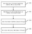
도 3은 본 발명의 일 실시예에 의한 가상 DAS 네트워크를 동작시키는 방법을 도시하는 단순화된 흐름도이다. 단계 310에서, 제1 BTS로부터 복수의 제1 캐리어들을 포함하는 제1 신호가 수신될 수 있다. 단계 312에서, 제2 BTS로부터 복수의 제2 캐리어들을 포함하는 제2 신호가 수신될 수 있다. 단계 314에서, 상기 제1 신호 및 제2 신호가 제1 DRU로 라우팅될 수 있다. 단계 316에서, 상기 제1 신호와 제2 신호가 제2 DRU로 라우팅될 수 있다.3 is a simplified flow diagram illustrating a method of operating a virtual DAS network in accordance with one embodiment of the present invention. In
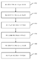
도 4는 본 발명의 일 실시예에 의한 가상 DAS 네트워크를 동작시키는 방법을 도시하는 단순화된 흐름도이다. 단계 410에서, 제1 BTS로부터 제1 신호가 수신될 수 있다. 단계 412에서, 제2 BTS로부터 제2 신호가 수신될 수 있다. 단계 414에서, 상기 제1 신호가 제1 DRU로 라우팅될 수 있다. 단계 416에서, 상기 제2 신호가 제2 DRU로 라우팅될 수 있다. 그 뒤에 상기 BTSs로부터 수신되는 신호들은 다르게 라우팅될 수 있다(예컨대, 네트워크 수요에 기초하여). 예를 들어, 단계 418에서, 제3 신호가 상기 제1 BTS로부터 수신될 수 있다. 단계 420에서, 상기 제3 신호는, 상기 제1 DRU가 아니라 상기 제2 DRU로 라우팅될 수 있다. 도 3 및 4의 기술(記述)은 도 1 및 2에 제공된 기술 중 어느 것과 대응될 수 있음이 명백하다.4 is a simplified flow diagram illustrating a method for operating a virtual DAS network in accordance with one embodiment of the present invention. In
도 3 또는 도 4에 도시된 구체적인 단계들은 본 발명의 몇몇 실시예에 의한 가상 DAS 네트워크를 동작시키는 특정 방법을 제공한다. 다른 실시예들에 의하면, 다른 시퀀스의 단계들이 수행될 수 있다. 예를 들어, 본 발명의 다른 실시예는 상기 단계들을 다른 순서로 수행할 수 있다. 또한, 도 3 또는 도 4에 도시된 개별 단계들은 각 단계에 적합하도록 다양한 시퀀스로 수행될 수 있는 다수의 하위 단계들을 포함할 수 있다. 또한, 특정 애플리케이션에 따라서는 추가적인 단계들이 부가 또는 제거될 수 있다. 당업자는 많은 변형, 수정 및 대안을 인식할 수 있을 것이다.The specific steps shown in FIG. 3 or FIG. 4 provide a particular method of operating a virtual DAS network according to some embodiments of the present invention. According to other embodiments, steps of different sequences may be performed. For example, another embodiment of the present invention may perform the steps in a different order. In addition, the individual steps shown in FIG. 3 or 4 may include a number of sub-steps that may be performed in various sequences to suit each step. Further, depending on the particular application, additional steps may be added or removed. Those skilled in the art will recognize many variations, modifications, and alternatives.
본 발명의 일 실시예에 의한 리모트 라디오 헤드 유닛(Remote Radio Head Unit)의 일 실시예는 도 5에 도시된다. 500A로 표시된 파이버 1은 BTS와 리모트 라디오 헤드 유닛 간에 데이터를 전송하는 고속 파이버 케이블일 수 있다. 500B로 표시된 파이버 2는 다른 리모트 라디오 헤드 유닛들을 데이지 체인 연결하는데 사용될 수 있고, 이들은 이렇게 해서 BTS 또는 DAU에 상호 접속된다. 소프트웨어 정의 디지털 플랫폼 516은, 일반적으로 FPGA에서 또는 그 등가물에서, 기저대역(baseband) 신호 프로세싱을 수행할 수 있다. 빌딩 블록 502은 시리얼라이저/디시리얼라이저(Serializer/Deserializer)이다. 디시리얼라이저 부분은 광 섬유(혹은 광 파이버) 501로부터 직렬(serial) 입력 비트 스트림을 추출할 수 있고 이를 병렬(parallel) 비트 스트림으로 변환한다. 시리얼라이저 부분은 상기 리모트 라디오 헤드 유닛으로부터 상기 BTS로 데이터를 전송하기 위한 역(inverse) 동작을 행한다. 일 실시예에서, 두 개의 다른 비트 스트림들은 하나의 파이버를 통해 서로 다른 광 파장을 사용하여 상기 BTS와 통신하지만, 다른 구성에서는 다수의 파이버들이 사용될 수도 있다. 디프레이머 504는 유입되는 비트 스트림의 구조를 해독하고 이 디프레밍된 데이터를 크레스트 팩터 감소(Crest Factor Reduction) 알고리즘 509로 송신한다. 상기 크레스트 팩터 감소 블록 509는 유입 신호의 첨두 대 평균 비를 감소시킬 수 있고, 이에 의해 전력 증폭기 DC-RF 변환 효율을 향상시킨다. 다음으로 이 파형은 디지털 사전왜곡기(Digital Predistorter) 블록 508로 제공될 수 있다. 상기 디지털 사전왜곡기는 적응형(adaptive) 피드백 루프의 전력 증폭기 521의 비선형성을 보상할 수 있다. 디지털 업컨버터 510은 상기 디프레이밍된 신호를 필터링하고 디지털 방식으로 IF 주파수로 변환할 수 있다. 프레이머 504는 두 개의 디지털 다운컨버터(digital downconverter) 506, 507로부터 데이터를 가져올 수 있고 이를 광 섬유 501을 통해 상기 BTS로 전송하기 위한 프레임으로 팩(pack)할 수 있다. 구성요소 511 및 512는 두 개의 아날로그 수신 신호를 디지털 신호로 변환하는데 이용될 수 있는 아날로그-디지털 컨버터이다. 수신기는 다운컨버터(downconverter) 517 및 대역 통과 필터(Band Pass Filter) 523을 포함하는 다이버시티 브랜치(diversity branch)를 포함한다. 메인 브랜치(main branch)는 듀플렉서(duplexer) 524 및 다운컨버터 518로 구성된 수신기 경로를 갖는다. 몇몇 실시예에서, 다운컨버터 517과 518 모두 또는 어느 하나는 적분 업링크 저잡음(integral uplink low-noise) 증폭기를 가질 수 있다.An embodiment of a remote radio head unit according to an embodiment of the present invention is shown in Fig.
전력 증폭기는 피드백 경로 내에서 출력 신호의 복제물을 추출하기 위한 출력 커플러(coupler)를 갖는다. 피드백 신호는 다운컨버터 519에 의해 IF 주파수 또는 기저대역으로 주파수 변환되고 아날로그-디지털 컨버터 513에 제공된다. 이러한 피드백 신호는 상기 전력 증폭기에 의해 생성된 비선형성을 보상하기 위해 디지털 사전왜곡을 수행하는 적응형 루프에서 사용된다.The power amplifier has an output coupler for extracting a replica of the output signal within the feedback path. The feedback signal is frequency converted to an IF frequency or baseband by a
이더넷 케이블은 국지적으로 상기 리모트 라디오 헤드 유닛과 통신하기 위해 사용된다. 스위치 526은 FPGA 또는 CPU로의 용이한 액세스를 가능하게 하기 위해 사용된다. DC 파워 컨버터들 528 및 529는 상기 리모트 라디오 헤드 유닛을 위한 원하는 DC 전압을 얻기 위해 사용된다. 외부 전압이 직접 RRU로 접속되거나 DC 파워가 이더넷 케이블을 통해 공급될 수 있다.An Ethernet cable is used locally to communicate with the remote radio head unit. The
본 실시예의 설명은 제2 광 섬유 접속이 다른 리모트 라디오 헤드 유닛들로 데이지 체인 연결하는 능력을 제공하는 애플리케이션에 관한 것이지만, 다른 실시예는 적합한 애플리케이션들을 위한 수정된 "하이브리드 스타(hybrid star)" 배열을 지지하기 위해 다수의 광 섬유 접속들을 제공하고, 이들은 이러한 특정 광 전송 네트워크 형태를 좌우한다.Although the description of this embodiment is directed to an application that provides the ability for a second fiber connection to daisy-chain to other remote radio head units, other embodiments may include a modified "hybrid star" arrangement To provide a plurality of optical fiber connections, which dominate this particular type of optical transmission network.
도 6을 참조하면, 본 발명의 다른 실시예가 다음과 같이 기술될 수 있다. 이전의 배열에서, 실시예는 동일한 무선 운영자에 속하는 별개의 두 기지국으로부터의 다운링크 신호들이 각각 DAU1 및 DAU2 입력 포트로 들어가게 하는 것을 포함하였다. 다른 실시예에서, 예컨대, 다른 무선 운영자에 속하는 제2 기지국으로부터의 제2 복합(composite) 다운링크 입력 신호가 DAU2 RF 입력 포트에서 DAU2로 들어간다. 이 실시예에서, 제1 운영자와 제2 운영자 모두에 속하는 신호들은 변환되어 RRU1 603, RRU2 604, RRU3 605 및 RRU4 606으로 각각 전송된다. 이 실시예는 다수의 무선 운영자들이 DAU1 601, DAU2 602, RRU1 603, RRU2 604, RRU3 605 및 RRU4 606으로 구성되는 공통의 인프라스트럭처를 공유하는 뉴트럴 호스트 무선 시스템의 일 예를 제공한다. DAU1 601과 DAU2 602가 케이블 613을 통해 접속될 수 있기 때문에 제1 운영자와 제2 운영자 모두에 속하는 신호들은 여기서 언급된 모든 RRUs에 도달할 수 있다. 이렇게 해서, DAU1 601에 제공되는 대역폭 607과 DAU2 602에 제공되는 대역폭 608은 여기서 언급된 RRUs 중 모두에 그리고 어느 것에든 도달할 수 있다. 예를 들어, 모든 캐리어 대역폭 607 및 608은, 대역폭 출력 609에 도시된 것처럼, RRU1 603에 제공될 수 있다. 이와 달리, 대역폭 출력 610에 도시된 것과 같이, 대역폭 입력 1, 3, 4, 6만이 RRU2 604에 제공되어야 할 수도 있다. 이에 더하여, 대역폭 출력 611에 도시된 것과 같이, 대역폭 입력 2, 6만이 RRU3 605에 제공되어야 할 수도 있다. 마지막으로, 대역폭 출력 612에 도시된 것과 같이, RRU4 606은 대역폭 입력 1, 4, 5 및 8만을 제공해야 할 수도 있다. 이렇게 해서, 본 발명의 실시예들에 의하면, 예컨대, 각각이 DAU1과 DAU2를 제어하는 두 개의 다른 캐리어들이 모든 RRUs에 커버리지를 제공할 수 있게 된다. 상기한 특징과 효과들은 두 개의 무선 운영자들 각각에 생긴다.Referring to FIG. 6, another embodiment of the present invention can be described as follows. In the previous arrangement, the embodiment involved causing downlink signals from two different base stations belonging to the same wireless operator to enter the DAU1 and DAU2 input ports, respectively. In another embodiment, for example, a second composite downlink input signal from a second base station belonging to another wireless operator enters DAU2 at the DAU2 RF input port. In this embodiment, signals belonging to both the first operator and the second operator are converted and transmitted to
도 6을 참조하면, RRU 내에 존재하는 디지털 업컨버터(Digital Up Converter)들은 FDMA, CDMA, TDMA, 및 OFDMA 등을 포함하는 변조 타입 및 다양한 신호 포맷을 처리하도록 프로그래밍될 수 있다. 또한, 개별 RRUs 내에 존재하는 상기 디지털 업컨버터들은 다양한 주파수 대역 내에서 전송되어야 하는 신호들과 동작하도록 프로그래밍될 수 있다. 광대역 CDMA 신호가, 예컨대, DAU1로의 입력 포트에서 캐리어 1에 대응하는 대역폭 내에 존재하는 본 발명의 일 실시예에서, RRU1, RRU2 및 RRU4의 안테나 포트에서의 전송 신호는 DAU1로의 입력 포트에서 캐리어 1에 대응하는 대역폭 내에 존재하는 상기 신호와 거의 동일한 광대역 CDMA 신호일 것이다.Referring to FIG. 6, the digital up converters present in the RRU may be programmed to process modulation types and various signal formats, including FDMA, CDMA, TDMA, and OFDMA, and the like. In addition, the digital upconverters present in individual RRUs may be programmed to operate with signals to be transmitted in various frequency bands. In one embodiment of the invention where a wideband CDMA signal is present, for example, in a bandwidth corresponding to
도 6을 다시 참조하면, 각각의 RRUs 내에 존재하는 디지털 업컨버터는 개별 RRU 안테나 포트들의 각각으로 원하는 복합 신호 포맷을 전송하도록 프로그래밍될 수 있다. 일 예로서, RRU1 및 RRU2 내에 존재하는 디지털 업컨버터들은 위에서 설명한 바와 같이, RRU1의 안테나 포트에 존재하는 신호가 도 6에 610으로서 도시된 스펙트럼 프로파일에 대응하게 되도록, 그리고, RRU2의 안테나 포트에 존재하는 신호가 도 6에 609으로서 도시된 스펙트럼 프로파일에 대응하게 되도록 동적으로 소프트웨어 재구성가능하다. 이러한 RRU 용량의 동적 재배열에 관한 하나의 애플리케이션은, 예컨대, 회사 미팅이 갑자기 RRU2의 커버리지 구역에 대응되는 회사의 구역에서 소집되었을 경우일 수 있다. 몇몇 실시예에 관한 설명은 서로 다른 주파수에 존재하는 기지국 신호들 607 및 608에 관한 것이지만, 본 발명의 시스템과 방법은 기지국 신호들 607 및 608의 일부인 하나 또는 그 이상의 캐리어들이 동일한 주파수인 구성을 용이하게 지원할 수 있고, 이는 기지국 신호들이 원하는 RRU로 스위칭, 라우팅, 디지털화 및 패킷화되기 때문이다.Referring back to FIG. 6, the digital upconverters present in each RRUs may be programmed to transmit the desired composite signal format to each of the individual RRU antenna ports. As an example, the digital upconverters present in RRU1 and RRU2 may be configured such that the signal present at the antenna port of RRU1 corresponds to the spectral profile shown as 610 in Fig. 6 and is present at the antenna port of RRU2, Lt; RTI ID = 0.0 > 609 < / RTI > in FIG. One application for dynamic rearrangement of such RRU capacity may be, for example, when a corporate meeting is suddenly convened in an area of the company corresponding to the coverage area of RRU2. Although the description of some embodiments relates to base station signals 607 and 608 that are at different frequencies, the systems and methods of the present invention facilitate the configuration in which one or more carriers that are part of base station signals 607 and 608 are the same frequency Because the base station signals are switched, routed, digitized, and packetized into the desired RRU.
본 발명에 의한 분산 안테나 시스템의 다른 실시예는 도 7에 도시된다. 업링크 신호들과 관련하여 유연성있는 동시 송출의 동작을 설명하기 위해 유연성있는 동시 송출 시스템 700이 사용될 수 있다. 도 6을 참조하여 다운링크 신호들과 관련해서 위에서 논의된 바와 같이, 도 7에 도시된 업링크 시스템은 크게 701에서 표시된 DAU1, 703에서 표시된 RRU1, 704에서 표시된 RRU2, 702에서 표시된 DAU2, 705에서 표시된 RRU3, 및 706에서 표시된 RRU4로 구성된다. 도 6을 참조하여 설명된 다운링크 동작과 유사한 방식으로, 도 7에 도시된 업링크 시스템의 동작이 다음과 같이 이해될 수 있다.Another embodiment of a distributed antenna system according to the present invention is shown in Fig. A flexible
RRU1 703, RRU2 704, RRU3 705 및 RRU4 706의 각각에 존재하는 디지털 다운컨버터들은 상기한 바와 같이, RRU1 703, RRU2 704, RRU3 705 및 RRU4 706의 수신 안테나 포트들에 존재하는 적합한 원하는 신호 포맷(들)의 업링크 신호들이 프로세싱 및 필터링되어야 하는 원하는 업링크 대역(들)에 기초하여 선택되고, 변환되어 DAU1 701 또는 DAU2 702의 어느 하나의 적합한 업링크 출력 포트로 전송되도록 동적으로 소프트웨어 구성된다. DAUs 및 RRUs는 공중 인터페이스 표준(Common Public Interface Standard; CPRI)을 사용하여 자신들의 개별 라디오 시그너처(signature)에 대응하는 개별 데이터 패킷들을 프레이밍한다. 개별 RRUs로 데이터 패킷들을 고유하게 식별한다면 다른 인터페이스 표준들이 적용가능하다. 개별 데이터 패킷에 대응하는 RRU 및 DAU를 식별하는 헤더 정보는 데이터 패킷과 함께 전송된다.The digital downconverters present in each of
도 7에 도시된 실시예에 대한 일 예에서, RRU1 703 및 RRU3 705는 캐리어 2 대역폭 내의 업링크 신호들을 수신하도록 구성되는 반면, RRU2 704 및 RRU4 706은 모두 캐리어 2 대역폭 내의 업링크 신호들을 거부하도록 구성된다. RRU3 705가 그 수신 안테나 포트에서 캐리어 2 대역폭 내의, 적절히 필터링되고 프로세싱될 수 있을 만큼 충분히 강한 신호를 수신할 때, RRU3 내의 디지털 다운컨버터들이 프로세싱과 변환을 용이하게 한다. 유사하게, RRU1이 그 수신 안테나 포트에서 캐리어 2 대역폭 내의, 적절히 필터링되고 프로세싱될 수 있을 만큼 충분히 강한 신호를 수신할 때, RRU1 703 내의 디지털 다운컨버터들이 프로세싱과 변환을 용이하게 한다. RRU1 703 및 RRU3 705로부터의 신호들은 활성 상태인 신호 결합 알고리즘에 기초하여 결합되고, DAU1 701의 업링크 출력 포트에 접속된 기지국으로 공급된다. 동시 송출이라는 용어는 캐리어 2 대역폭 내의 업링크 및 다운링크 신호들과 관련하여 RRU1 703 및 RRU3 705의 동작을 설명하기 위해 자주 사용된다. 유연성있는 동시 송출이라는 용어는, 본 발명이 각각의 캐리어 대역폭에 대한 신호 결합 프로세스에 관여하는 특정 RRU의 동적 및/또는 수동 재배열을 지원한다는 사실을 가리킨다.7,
도 7을 참조하면, RRU1에 존재하는 디지털 다운컨버터들은 캐리어 1-8 대역폭 내의 신호들을 수신하고 프로세싱하도록 구성된다. RRU2에 존재하는 디지털 다운컨버터들은 캐리어 1, 3, 4 및 6 대역폭 내의 신호들을 수신하고 프로세싱하도록 구성된다. RRU3에 디지털 다운컨버터들은 캐리어 2 및 6 대역폭 내의 신호들을 수신하고 프로세싱하도록 구성된다. RRU4에 디지털 다운컨버터들은 캐리어 1, 4, 5 및 8 대역폭 내의 신호들을 수신하고 프로세싱하도록 구성된다. 네 개의 RRU의 각각의 내에서 수행되는 프로세싱으로 생기는 고속 디지털 신호들은 개별적으로 두 개의 DAUs로 라우팅된다. 상기한 바와 같이, 상기 네 개의 RRUs로부터의 업링크 신호들은 각각의 기지국에 대응하는 개별 DAU 내에서 결합된다.Referring to FIG. 7, the digital downconverters present in RRU1 are configured to receive and process signals within the carrier 1-8 bandwidth. The digital downconverters present in RRU2 are configured to receive and process signals in
본 발명의 일 국면은 각각의 RRU 내에 통합된 파일럿 비콘(Pilot Beacon) 기능을 포함한다. 일 실시예에서, 각각의 RRU는 이하에서 논의되는 바와 같이 고유한 소프트웨어 프로그래머블(software programmable) 파일럿 비콘을 포함한다. 이러한 방식은 CDMA 및/또는 WCDMA 인도어(indoor) DAS 네트워크에서의 사용을 위한 것이다. 매우 유사한 방식이 LTE 및 WiMAX같은 다른 타입의 네트워크들을 위한 인도어 위치 정확성 향상을 위해 효과적일 수 있다. 각각의 RRU는 상기 네트워크를 구성하는 DAUs을 통해 이미 감시되고 제어되기 때문에, 많은 비용을 들여 파일럿 비콘들의 리모트 감시 및 제어를 위한 추가적인 전용 무선 모뎀을 배치할 필요가 없다.One aspect of the present invention includes a Pilot Beacon function integrated into each RRU. In one embodiment, each RRU includes a unique software programmable pilot beacon, as discussed below. This approach is for use in CDMA and / or WCDMA indoor DAS networks. A very similar approach may be effective for improving indoor location accuracy for other types of networks such as LTE and WiMAX. Since each RRU is already monitored and controlled through the DAUs that make up the network, there is no need to place an additional dedicated radio modem for remote monitoring and control of the pilot beacons at high cost.
RRU 통합 파일럿 비콘 방식은 CDMA 및 WCDMA 네트워크 모두에서 사용된다. RRU 내의 각각의 운영 파일럿 비콘 기능은 (그 구역 내의)고유한 PN 코드를 사용하고, 이 PN 코드는 효과적으로 WCDMA 또는 CDMA 인도어 네트워크 커버리지 구역을 다수의 작은 "존(zone)"으로 분할한다(이들은 각각 저파워 파일럿 비콘의 커버리지 구역에 대응함). 상기 네트워크는 각각의 파일럿 비콘의 위치, PN 코드 및 RF 파워 레벨을 알 수 있다. 각각의 파일럿 비콘은 DAU로의 접속을 통해 WCDMA 또는 CDMA 네트워크에 동기화된다.The RRU integrated pilot beacon scheme is used in both CDMA and WCDMA networks. Each operating pilot beacon function in the RRU uses a unique PN code (within that zone), which effectively divides the WCDMA or CDMA Indoor Network coverage zone into a number of small "zones " Corresponding to the coverage area of the low power pilot beacon). The network can know the location of each pilot beacon, the PN code, and the RF power level. Each pilot beacon is synchronized to a WCDMA or CDMA network via a connection to the DAU.
"동적인" 기지국으로부터의 전송 신호와 달리, 파일럿 비콘 전송 신호는 유효하게 "정적(static)"이고 그 다운링크 메시지들은 네트워크 상태에 기초하여 시간에 따라 변화하지 않을 것이다.Unlike the transmission signal from the "dynamic" base station, the pilot beacon transmission signal is effectively "static" and the downlink messages will not change over time based on the network conditions.
WCDMA 네트워크에 있어서, 아이들(Idle) 모드에서는, 각각의 모바일 가입자 터미널이 기지국들 및 파일럿 비콘들에 의해 전송되는 다운링크 신호들의 파일럿 신호(Pilot Signal) 측정을 수행할 수 있다. WCDMA 모바일 가입자 터미널은 활성(Active) 모드로 전이될 때, 기지국들 및 파일럿 비콘들에 대한 모든 파일럿 신호 측정 결과를 서비스 제공 셀에 통지한다. CDMA 네트워크에 있어서, 동작은 매우 유사하다. 인도어 네트워크에 배치된 몇몇 RRU에 있어서, 상기 RRU는 파일럿 비콘으로 제공되거나 특정 운영자 대역폭 내의 모바일 가입자들에게 서비스를 제공할 수 있지만, 양쪽 다 아닐 수도 있다.In a WCDMA network, in idle mode, each mobile subscriber terminal can perform pilot signal measurements of downlink signals transmitted by base stations and pilot beacons. When the WCDMA mobile subscriber terminal transitions to active mode, it informs the serving cell of all pilot signal measurement results for base stations and pilot beacons. In a CDMA network, the operation is very similar. For some RRUs deployed in the Indian language network, the RRU may be provided as a pilot beacon or may serve mobile subscribers within a particular operator bandwidth, but not both.
WCDMA 네트워크에 있어서, 전세계적으로 표준화된 네트워크들의 기존의 고유한 기능들이 사용된다. WCDMA 모바일 가입자 터미널은 아이들 모드 또는 몇 가지 활성 모드들 중 어떤 모드에서는 가장 강한 CPICH RSCP(파일럿 비콘 코드 파워)를 측정할 수 있다. 또한, 아이들 모드 또는 몇 가지 활성 모드들 중 어떤 모드에서 모바일 가입자 터미널에 의한 CPICH Ec/No의 측정이 가능하다. 결과적으로, 모바일 가입자 터미널은 서비스 제공 기지국을 통해 모든 가능한 RSCP 및 Ec/No 측정 결과를(인도어이든 아웃도어이든) 네트워크에 통지한다. 그러한 정보에 기초하여, 가장 가능성이 높은 모바일 가입자 터미널 위치가 계산 및/또는 결정된다. CDMA 네트워크에 있어서, 동작은 본 명세서에 여기서 설명한 프로세스와 매우 유사하다.In WCDMA networks, existing, unique functions of globally standardized networks are used. The WCDMA mobile subscriber terminal can measure the strongest CPICH RSCP (pilot beacon code power) in idle mode or some of the active modes. It is also possible to measure the CPICH Ec / No by the mobile subscriber terminal in either the idle mode or some of the active modes. As a result, the mobile subscriber terminal notifies the network of all possible RSCP and Ec / No measurement results (whether Indoor or Outdoor) through the serving base station. Based on such information, the most likely mobile subscriber terminal location is calculated and / or determined. In a CDMA network, the operation is very similar to the process described herein.
도 6을 참조하여 이미 설명된 본 발명의 실시예는, 예컨대, DAU1로의 입력 포트에서 캐리어 1에 대응하는 대역폭 내에 존재하는 광대역 CDMA 신호를 갖는 것을 포함한다. 앞서 설명한 실시예에서, RRU1, RRU2 및 RRU4의 안테나 포트에서의 전송 신호는, DAU1로의 입력 포트에서 캐리어 1에 대응하는 대역폭 내에 존재하는 신호와 거의 동일한 광대역 CDMA 신호이다. 본 발명의 다른 실시예는 광대역 CDMA 신호가, 예컨대, DAU1로의 입력 포트에서 캐리어 1에 대응하는 대역폭 내에 존재하는 실시예이다. 그러나, 상기 다른 실시예에서, RRU1의 안테나 포트에서의 전송 신호는 이전의 실시예와 조금 다르다. 상기 다른 실시예에서는, 광대역 CDMA 신호가, 예컨대, DAU1로의 입력 포트에서 캐리어 1에 대응하는 대역폭 내에 존재한다. RRU1으로부터의 전송 신호는 DAU1으로의 입력 포트에 존재했던 상기 광대역 CDMA 신호와 특화된 WCDMA 파일럿 비콘 신호의 결합이다. 상기 WCDMA 파일럿 비콘 신호는 의도적으로 기지국 파일럿 비콘 신호의 레벨보다 훨씬 낮은 레벨로 설정된다.The embodiment of the present invention already described with reference to Fig. 6 includes, for example, having a wideband CDMA signal present in the bandwidth corresponding to
또 다른 실시예는 CDMA 신호들이 DAU1의 입력 포트에 접속된 기지국에 의해 생성되는 사례에 해당하는 도 8을 참조하여 설명될 수 있다. 이 또 다른 실시예에서, RRU1의 안테나 포트에서의 전송 신호는 DAU1으로의 입력 포트에 존재했던 CDMA 신호와 특화된 CDMA 파일럿 비콘 신호의 결합이다. 상기 CDMA 파일럿 비콘 신호는 의도적으로 기지국 파일럿 비콘 신호의 레벨보다 훨씬 낮은 레벨로 설정된다.Another embodiment may be described with reference to FIG. 8, which corresponds to an example where CDMA signals are generated by a base station connected to an input port of DAU1. In this alternative embodiment, the transmitted signal at the antenna port of RRU1 is a combination of a CDMA pilot signal and a specialized CDMA pilot beacon signal that were present at the input port to DAU1. The CDMA pilot beacon signal is intentionally set to a level much lower than the level of the base station pilot beacon signal.
본 발명의일 실시예는 인도어 무선 가입자들의 위치를 결정함에 있어서 향상된 정확도를 제공한다. 도 9는 다수의 리모트 라디오 헤드 유닛들(RRUs)과 중앙 디지털 액세스 유닛(Digital Access Unit; DAU)을 이용하는 전형적인 인도어 시스템을 도시한다. 각각의 리모트 라디오 헤드는 그에 의해 수신된 데이터에 고유한 헤드 정보를 제공한다. 이 헤더 정보는 모바일 사용자의 라디오 시그너처(signature)와 함께 상기 사용자가 특정 셀에 위치한 것으로 판단(localization)하는데 사용된다. DAU 신호 프로세싱은 개별 캐리어들과 이들의 대응 타임 슬롯들을 식별할 수 있다. 각각의 데이터 패킷에는 대응하는 RRU를 고유하게 식별하는 헤더가 포함된다. DAU는 캐리어 주파수와 개별 RRUs와 연관된 대응하는 타임 슬롯을 검출할 수 있다. DAU는 각각의 캐리어 주파수와 타임 슬롯을 개별 RRU로 식별하는 러닝(running) 데이터베이스를 갖는다. 상기 캐리어 주파수 및 타임 슬롯은 GSM 사용자를 고유하게 식별하는 라디오 시그너처이다.One embodiment of the present invention provides improved accuracy in determining the location of indoor wireless subscribers. Figure 9 shows a typical indoor system using a plurality of remote radio head units (RRUs) and a central digital access unit (DAU). Each remote radio head provides its own head information to the data received thereby. This header information is used to localize the mobile user's radio signature along with the user's location in a particular cell. DAU signal processing can identify individual carriers and their corresponding timeslots. Each data packet includes a header that uniquely identifies the corresponding RRU. The DAU can detect the carrier frequency and corresponding time slots associated with individual RRUs. The DAU has a running database that identifies each carrier frequency and time slot as separate RRUs. The carrier frequency and timeslot are radio signatures that uniquely identify a GSM user.
DAU는 도 10에 도시된 것과 같이, 이더넷 접속 또는 외부 모뎀을 통해 네트워크 운영 센터(Network Operation Center; NOC)와 통신한다. E911 콜이 시작되면 모바일 스위칭 센터(Mobile Switching Center; MSC)가 NOC와 함께 사용자가 콜을 한 대응하는 기지국 송수신기(Base Transceiver Station; BTS)를 식별할 수 있다. 상기 사용자의 위치가 BTS 셀 내인 것으로 판단될 수 있다. 다음으로 상기 NOC는 개별 DAUs에 E911 라디오 시그너처가 그들의 인도어 셀 내에서 활성인지를 판단하도록 요청한다. DAU는 활성 캐리어 주파수 및 타임 슬롯을 확인하기 위해 그 데이터베이스를 확인한다. 그 라디오 시그너처가 상기 DAU 내에서 활성이면, 그 DAU는 대응하는 RRU의 위치 정보를 상기 NOC에 제공할 것이다.The DAU communicates with a Network Operation Center (NOC) via an Ethernet connection or an external modem, as shown in FIG. When an E911 call is initiated, a Mobile Switching Center (MSC) can identify the corresponding base transceiver station (BTS) with which the user called with the NOC. It can be determined that the position of the user is within the BTS cell. The NOC then requests individual DAUs to determine if the E911 radio signature is active in their Indie cell. The DAU identifies its database to identify the active carrier frequency and timeslot. If the radio signature is active in the DAU, the DAU will provide location information of the corresponding RRU to the NOC.
본 발명의 다른 실시예는 LTE를 포함하여 인도어 무선 가입자들의 위치를 결정하는데 있어서 향상된 정확성을 제공한다. GSM은 사용자들을 구분하기 위해 개별 캐리어와 타임 슬롯을 사용하지만, LTE는 사용자들을 구분하기 위해 다수의 캐리어와 카임 슬록 정보를 사용한다. DAU는 동시에 LTE 사용자를 고유하게 식별하기 위해 다수의 캐리어들과 이들의 대응 타임 슬롯을 검출할 수 있다. DAU는 각각의 RRU에 대한 캐리어 주파수 및 타임 슬롯 라디오 시그너처를 식별하는 러닝 데이터베이스를 갖는다. 이 정보는 DAU로의 요청이 있을 때 상기 NOC로부터 검색될 수 있다.Other embodiments of the present invention provide improved accuracy in determining the location of Indoor wireless subscribers, including LTE. GSM uses separate carriers and timeslots to differentiate between users, but LTE uses multiple carriers and carousel information to differentiate between users. The DAU can detect multiple carriers and their corresponding time slots to uniquely identify an LTE user at the same time. The DAU has a running database that identifies the carrier frequency and time slot radio signatures for each RRU. This information can be retrieved from the NOC when there is a request to the DAU.
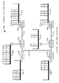
다음으로 도 11을 참조하면, 본 발명의 또 다른 실시예를 이해할 수 있다. 도 11의 실시예에서, 제1 복합 신호는 기지국 1105로부터 제1 DAU 1100의 RF 입력 포트에서 제1 DAU 1100으로 들어가고, 예컨대, 다른 무선 운영자에 속하는 제2 기지국 1110으로부터의 제2 복합 다운링크 입력 신호는 제2 DAU의 RF 입력 포트에서 제2 DAU 1115로 들어간다. DAU 1100은 직접 두 개의 링 1120 및 1125를 지원하고, DAU 1115는 직접 두 개의 링 1130 및 1135를 지원하며, 링 1140은 DAU 1100과 DAU 1105 사이에 공유된다. 상기 링들의 각각은 1145에 포괄적으로 표시되고, 예컨대, 광섬유 링크를 통해 접속된, 데이지 체인 연결된 DRUs를 포함한다. 채널 A는 채널 B와 정반대인 느낌으로 전송된다는 것을 알 수 있다. 서브세트 A 내의 다운링크 채널들은 각각의 링을 따라 시계 반대 방향으로 전송되는 반면, 서브세트 B 내의 채널들은 각각의 링을 따라 시계 방향으로 전송된다. 이 실시예에서, 제1 운영자 및 제2 운영자 모두에 속하는 신호들은 변환되어 링 1140 상의 DRUs 1145로 전송되는데, 이는 DAU 1100과 DAU 1105가 파이버 광 케이블 1140을 통해 데이지 체인 연결되어 있기 때문이다. 이 실시예는 다수의 무선 운영자들이 DAU 1100, DAU 1155, 및 DRUs 1145로 구성되는 공통의 인프라스트럭처를 공유하는 뉴트럴 호스트 무선 시스템의 일 예를 제공한다. 위에서 언급된 모든 특징들과 장점들은 상기 두 개의 무선 운영자들의 각각에서 나타난다. 도 11은 데이지 체인 스타일로 연결된 단 두 개의 DAUs만을 도시하지만, 더 많은 수의 DAUs를 데이지 체인 연결하는 것이 가능하고 데이지 체인 연결된 DAUs는 또한 상기 DRUs가 접속되는 방식과 유사한 링 형태로 배열될 수 있다.Next, another embodiment of the present invention can be understood with reference to FIG. In the embodiment of FIG. 11, a first composite signal enters the
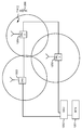
도 12를 참조하면, 본 발명의 다른 실시예가 더 잘 이해될 수 있다. 각각의 DRU는 특정 리모트 유닛으로부터의 파워 전송에 기초하여 조정될 수 있는 커버리지 반경을 갖는다. DAU는 다양한 DRU의 전송 파워를 제어하고 전체 커버리지 구역을 최적화할 수 있다. 도시된 실시예에서, 다시 NOC(도시되지 않음)의 제어 하에 있는 DAU 1202는 기지국 1201과 연관되고 세 개의 DRUs 1203, 1204 및 1205와 인터페이스한다. 모바일 디바이스를 갖는 사용자 1206은 상기 세 개의 DRUs에 의해 커버되는 구역 전체에서 상대적으로 균일한 커버리지를 제공받는다.Referring to Figure 12, another embodiment of the present invention can be better understood. Each DRU has a coverage radius that can be adjusted based on the power transmission from a particular remote unit. The DAU can control the transmission power of various DRUs and optimize the entire coverage area. In the illustrated embodiment, a
다음으로 도 13을 참조하면, 또 다른 실시예가 더 잘 이해될 수 있다. 입력 주파수 대역 1305 내지 1330(여기서는 700, 800, 850, 1900, 2100 및 2600 MHz의 6개의 주파수 대역으로 표시됨)은 BTSs(도시되지 않음)로부터 DAU 1300으로 입력된다. DAU는, 본 명세서에서 논의되는 다른 기능들 중에서, 각각의 대역에 대한 RF IN 부분과, 원하는 커버리지를 얻기 위한 세 개의 링 1335, 1340 및 1345를 따라 데이지 체인 연결된, DRU1 내지 DRU 60으로 표시된 복수의 DRUs로 주파수 대역들을 분배하는 디지털 분배 매트릭스(digital distribution matrix)를 포함한다. 상기 주파수 대역들은 DRUs의 모두 또는 그 서브세트로 전송된다. 주파수 대역들, DAUs, DRUs 및 링들의 특정 개수는 단지 예시일 뿐이며, 실제로는 네트워크의 요구 및 수행 능력에 적합한 임의의 개수일 수 있다.Referring now to Figure 13, yet another embodiment can be better understood.
다음으로 도 14를 참조하면, DAU와 DRU에 내장된, 이들 디바이스들의 주요 기능들의 동작을 제어하는 소프트웨어가 더 잘 이해될 수 있다. 구체적으로, DAU 임베디드 소프트웨어 제어 모듈 1400은 DAU 관리 제어 모듈 1405 및 DAU 감시 모듈 1410을 포함한다. DAU 관리 제어 모듈 1405은 NOC 1415와 통신하고, DAU 감시 모듈 1410과도 통신한다. 이러한 주요 기능의 하나는 원하는 용량 및 목표 처리량을 충족시키기 위해 특정 DRU 또는 특정 그룹의 DRUs에 배정되는 라디오 리소스(예컨대, RF 캐리어, CDMA 코드 또는 TDMA 타임 슬롯)의 적절한 양을 결정하고 그리고/또는 설정하는 것이다. 위에서 살펴본 것처럼, 적어도 몇몇 실시예에서는, NOC 1415가 DAS 동작을 감시하고 DAU뿐 아니라 DRUs의 다양한 기능을 구성하기 위한 명령들을 DAUs로 보낸다.Referring next to Fig. 14, the software that controls the operation of the DAUs and the main functions of these devices embedded in the DRU can be better understood. Specifically, the DAU embedded
DAU 감시 모듈은 다른 기능에 더하여 어느 캐리어와 그에 대응하는 타임 슬롯이 각각의 DRU에 대해 활성인지를 검출한다. DAU 관리 제어 모듈은 제어 프로토콜을 통하여 파이버 광 링크 제어 채널을 이용하여 DRU 임베디드 소프트웨어 제어 모듈 1420과 통신한다. 일 실시예에서, 상기 제어 프로토콜은, 제어 정보 및 데이터가 메시지로서 함께 DRUs로 전송될 수 있도록, 데이터의 패킷들과 함께 헤더를 포함한다. DRU 내에서 헤더가 제어하게 될 DRU 기능들 및 특징들은 구현하기에 따라 달라지고, 업링크 및 다운링크 파워의 측정, 업링크 및 다운링크 의 이득 측정, 및 DRU 내의 알람(alarm) 감시를 포함할 수 있다.The DAU monitoring module detects, in addition to other functions, which carrier and its corresponding time slot are active for each DRU. The DAU management control module communicates with the DRU embedded
DRU 임베디드 소프트웨어 제어 모듈 내의 DRU 관리 제어 모듈 1425는 특정 DRU 또는 특정 그룹의 DRUs에 의해 특정 라디오 리소스가 전송되게 하거나 전송되지 않도록 하기 위해 모든 DRU 디지털 업컨버터들 1430의 개별 파라미터들을 설정하고, 특정 DRU 또는 특정 그룹의 DRUs에 의해 특정 라디오 리소스가 전송되게 하거나 전송되지 않도록 하기 위해 모든 DRU 디지털 다운컨버터들 1435의 개별 파라미터들을 설정한다. 또한, DRU 임베디드 소프트웨어 제어 모듈은, DRU 파일럿 비콘(Pilot Beacon) 1445와 통신하는 DRU 파일럿 비콘 제어 모듈 1440을 포함한다.The DRU management control module 1425 in the DRU embedded software control module sets individual parameters of all DRU
다음으로 도 15를 참조하면, DAUs의 데이지 체인 배열의 일 실시예가 DRUs의 데이지 체인 배열과 함께 도시된다. 일 실시예에서, 복수의 기지국 1500A~1500n은 각각 DAUs 1505A~n 중 하나와 연관된다. DAUs는 데이지 체인 연결되고, 각각의 DAU는 링 형태로 배열될 수도 있고 그렇지 않을 수도 있는 DRUs의 데이지 체인들 1510A~1510m 중 하나 또는 그 이상과 통신한다. 앞서 논의된 것처럼 DAUs 또한 링 형태로 구성될 수 있음을 알 수 있다.Referring now to FIG. 15, one embodiment of a daisy chain arrangement of DAUs is shown with a daisy chain arrangement of DRUs. In one embodiment, the plurality of
어느 캐리어와 각각의 캐리어에 대응하는 타임 슬롯이 각각의 DRU에 대해 활성인지를 검출하는 DAU 감시 모듈 내에서 동작하는 알고리즘은, 예컨대, DAU 리모트 감시 및 제어 기능 1415에 의해 DAU 관리 제어 모듈로 그 값이 전달되는 미리 정해진 문턱값보다 큰 퍼센티지만큼 특정 다운링크 캐리어가 로딩될 때가 언제인지를 식별하는 것을 돕기 위해 DAU 관리 제어 모듈에 정보를 제공한다. 이러한 상황이 되면, DAU 관리 제어 모듈은 특정 DRU가 그 커버리지 구역 내에서 필요로 하는 (RF 캐리어, CDMA 코드 또는 TDMA 타임 슬롯같은) 추가적인 라디오 리소스들을 상기 특정 DRU가 사용하게 하기 위해 이러한 리소스들을 배치하기 시작하도록, 반드시 그래야 하는 것은 아니지만 일반적으로는 서서히, 시스템 구성을 적응적으로 변경할 수 있다. 동시에, 통상적으로 DAU 관리 제어 모듈은 DRU가 그 커버리지 구역 내에서 더 이상 필요로 하지 않는 (RF 캐리어, CDMA 코드 또는 TDMA 타임 슬롯같은) 일정한 라디오 리소스를 제거하기 시작하기 위해, 일반적으로 서서히, 시스템 구성을 적응적으로 변경한다.An algorithm operating in the DAU monitoring module that detects which carrier and time slot corresponding to each carrier is active for each DRU is determined by the DAU remote monitoring and
본 명세서에 개시된 예시와 실시예들은 단지 설명을 위한 것이고 당업자는 그에 대한 다양한 변경 및 수정을 도출해 낼 수 있으며, 이들은 첨부된 특허청구범위의 영역과 본 출원의 사상 및 범위 내에 포함되어야 한다는 점에 유의하여야 한다.It is to be understood that the examples and embodiments disclosed herein are for illustrative purposes only and that those skilled in the art can make various changes and modifications thereto which are within the scope of the appended claims and the spirit and scope of the present application shall.
Claims (22)
복수의 제2 캐리어들을 포함하는 제2 신호를 제공하는 제2 BTS;
각각이 상기 제1 BTS 또는 상기 제2 BTS 중 적어도 하나에 연결되는 하나 또는 그 이상의 디지털 액세스 유닛(digital access unit; DAU)의 세트; 및
각각이 상기 하나 또는 그 이상의 DAU 중 하나에 연결되고 상기 제1 신호 또는 상기 제2 신호를 전파하는 하나 또는 그 이상의 디지털 리모트 유닛(digital remote unit; DRU)의 세트
를 포함하는 네트워크.
A first base transceiver station (BTS) providing a first signal comprising a plurality of first carriers;
A second BTS providing a second signal comprising a plurality of second carriers;
A set of one or more digital access units (DAUs), each of which is connected to at least one of the first BTS or the second BTS; And
A set of one or more digital remote units (DRUs), each coupled to one of the one or more DAUs and propagating the first signal or the second signal
≪ / RTI >
상기 제1 BTS는 제1 인프라스트럭처 공급자와 관련되고, 상기 제2 BTS는 제2 인프라스트럭처 공급자와 관련되는, 네트워크.
The method according to claim 1,
Wherein the first BTS is associated with a first infrastructure provider and the second BTS is associated with a second infrastructure provider.
상기 제1 인프라스트럭처 공급자와 상기 제2 인프라스트럭처 공급자는 동일한 인프라스트럭처 공급자인, 네트워크.
3. The method of claim 2,
Wherein the first infrastructure provider and the second infrastructure provider are the same infrastructure provider.
하나 또는 그 이상의 BTS는 서로 다른 전파 프로토콜(broadcast protocol)을 사용하여 복수의 캐리어들을 포함하는 신호를 제공하는, 네트워크.
The method according to claim 1,
Wherein one or more BTSs provide signals comprising a plurality of carriers using different broadcast protocols.
상기 서로 다른 전파 프로토콜은 CDMA 또는 WCDMA 중 적어도 하나를 포함하는, 네트워크.
5. The method of claim 4,
Wherein the different propagation protocols comprise at least one of CDMA or WCDMA.
상기 서로 다른 전파 프로토콜은 LTE를 포함하는, 네트워크.
5. The method of claim 4,
Wherein the different propagation protocols include LTE.
상기 하나 또는 그 이상의 DAU는 이더넷 케이블, 광섬유(Optical Fiber), 마이크로파 가시거리 링크(Microwave Line of Sight Link), 무선 링크, 또는 위성 링크(Satellite Link) 중 적어도 하나를 통해 연결되는 복수의 DAU들을 포함하는 네트워크.
The method according to claim 1,
The one or more DAUs include a plurality of DAUs connected through at least one of an Ethernet cable, an optical fiber, a Microwave Line of Sight Link, a wireless link, or a Satellite Link. Network.
하나 또는 그 이상의 DAU는 이더넷 케이블, 광섬유(Optical Fiber), 마이크로파 가시거리 링크(Microwave Line of Sight Link), 무선 링크, 또는 위성 링크(Satellite Link) 중 적어도 하나를 통해 복수의 DRU들에 연결되는 복수의 DAU들을 포함하는 네트워크.
8. The method of claim 7,
One or more DAUs may be coupled to a plurality of DRUs via at least one of an Ethernet cable, an optical fiber, a Microwave Line of Sight Link, a wireless link, or a Satellite Link. ≪ / RTI >
상기 하나 또는 그 이상의 DRU는 데이지 체인 배열로 연결되는 복수의 DRU들을 포함하는 네트워크.
The method according to claim 1,
Wherein the one or more DRUs comprise a plurality of DRUs connected in a daisy chain arrangement.
상기 하나 또는 그 이상의 DRU는 성상(star configuration)으로 상기 하나 또는 그 이상의 DAU에 연결된 복수의 DRU들을 포함하는 네트워크.
The method according to claim 1,
Wherein the one or more DRUs comprise a plurality of DRUs connected to the one or more DAUs in a star configuration.
상기 하나 또는 그 이상의 DAU의 각각은 이더넷 케이블, 광섬유(Optical Fiber), 마이크로파 가시거리 링크(Microwave Line of Sight Link), 무선 링크, 또는 위성 링크(Satellite Link) 중 적어도 하나를 통해 상기 제1 BTS 또는 상기 제2 BTS 중 적어도 하나에 연결되는 네트워크.
The method according to claim 1,
Wherein each of the one or more DAUs is coupled to the first BTS or the second BTS via at least one of an Ethernet cable, an optical fiber, a Microwave Line of Sight Link, a wireless link, Wherein the second BTS is connected to at least one of the second BTSs.
제1 기지국 송수신기(BTS)로부터 복수의 제1 캐리어들을 포함하는 제1 신호를 수신하는 단계;
제2 BTS로부터 복수의 제2 캐리어들을 포함하는 제2 신호를 수신하는 단계;
제1 디지털 리모트 유닛(DRU)으로 상기 제1 신호 및 상기 제2 신호를 라우팅하는 단계; 및
제2 DRU로 상기 제1 신호 및 상기 제2 신호를 라우팅하는 단계
를 포함하는 가상 DAS 네트워크 작동 방법.
A method for operating a distributed antenna system (DAS) network,
Receiving a first signal comprising a plurality of first carriers from a first base station transceiver (BTS);
Receiving a second signal comprising a plurality of second carriers from a second BTS;
Routing the first signal and the second signal to a first digital remote unit (DRU); And
Routing the first signal and the second signal to a second DRU
Gt; DAS < / RTI >
지리적 사용 패턴에 기초하여, 상기 제1 DRU와 상기 제2 DRU를 포함하는 복수의 DRU들 중 하나와 상기 제1 신호 및 상기 제2 신호를 연관시키는 단계
를 더 포함하는 가상 DAS 네트워크 작동 방법.
13. The method of claim 12,
Associating the first signal and the second signal with one of a plurality of DRUs comprising the first DRU and the second DRU based on a geographic usage pattern
Further comprising the steps of:
상기 제1 신호 및 상기 제2 신호를 제2 DRU로 라우팅하는 단계는 복수의 DAU들을 통해 상기 제1 신호 및 상기 제2 신호를 라우팅하는 단계를 포함하는 가상 DAS 네트워크 작동 방법.
13. The method of claim 12,
Wherein routing the first signal and the second signal to a second DRU comprises routing the first signal and the second signal via a plurality of DAUs.
상기 제1 BTS는 제1 인프라스트럭처 공급자와 관련되고, 상기 제2 BTS는 제2 인프라스트럭처 공급자와 관련되는, 가상 DAS 네트워크 작동 방법.
13. The method of claim 12,
Wherein the first BTS is associated with a first infrastructure provider and the second BTS is associated with a second infrastructure provider.
상기 제1 인프라스트럭처 공급자와 상기 제2 인프라스트럭처 공급자는 동일한 인프라스트럭처 공급자인, 가상 DAS 네트워크 작동 방법.
16. The method of claim 15,
Wherein the first infrastructure provider and the second infrastructure provider are the same infrastructure provider.
제1 기지국 송수신기(BTS)로부터 제1 신호를 수신하는 단계;
제2 BTS로부터 제2 신호를 수신하는 단계;
제1 디지털 리모트 유닛(DRU)으로 상기 제1 신호를 라우팅하는 단계;
제2 DRU로 상기 제2 신호를 라우팅하는 단계;
상기 제1 BTS로부터 제3 신호를 수신하는 단계; 및
상기 제2 DRU로 상기 제3 신호를 라우팅하는 단계
를 포함하는 가상 DAS 네트워크 작동 방법.
A method for operating a distributed antenna system (DAS) network,
Receiving a first signal from a first base station transceiver (BTS);
Receiving a second signal from a second BTS;
Routing the first signal to a first digital remote unit (DRU);
Routing the second signal to a second DRU;
Receiving a third signal from the first BTS; And
Routing the third signal to the second DRU
Gt; DAS < / RTI >
상기 제1 DRU를 복수의 BTS들 중 하나로 반복적으로 배정하는 단계를 더 포함하고,
상기 복수의 BTS들은 상기 제1 BTS 및 상기 제2 BTS를 포함하는,
가상 DAS 네트워크 작동 방법.
18. The method of claim 17,
Further comprising the step of repeatedly allocating the first DRU to one of a plurality of BTSs,
Wherein the plurality of BTSs comprises the first BTS and the second BTS.
How the virtual DAS network works.
상기 제1 DRU는 상기 네트워크 내의 DRU들에 걸쳐서 결합된 BTS 리소스들을 고르게 분배하려는 시도 중에 적어도 부분적으로 배정되는,
가상 DAS 네트워크 작동 방법.
19. The method of claim 18,
Wherein the first DRU is at least partially allocated during an attempt to evenly distribute the combined BTS resources across DRUs in the network,
How the virtual DAS network works.
상기 제2 DRU로 상기 제3 신호를 라우팅하는 단계는 복수의 DAU들을 통해 상기 제3 신호를 라우팅하는 단계를 포함하는, 가상 DAS 네트워크 작동 방법.
18. The method of claim 17,
Wherein routing the third signal to the second DRU comprises routing the third signal over a plurality of DAUs.
상기 제1 BTS는 제1 인프라스트럭처 공급자와 관련되고, 상기 제2 BTS는 제2 인프라스트럭처 공급자와 관련되는,
가상 DAS 네트워크 작동 방법.
18. The method of claim 17,
Wherein the first BTS is associated with a first infrastructure provider and the second BTS is associated with a second infrastructure provider,
How the virtual DAS network works.
상기 제1 인프라스트럭처 공급자와 상기 제2 인프라스트럭처 공급자는 동일한 인프라스트럭처 공급자인, 가상 DAS 네트워크 작동 방법.22. The method of claim 21,
Wherein the first infrastructure provider and the second infrastructure provider are the same infrastructure provider.
Applications Claiming Priority (3)
| Application Number | Priority Date | Filing Date | Title |
|---|---|---|---|
| US201161556715P | 2011-11-07 | 2011-11-07 | |
| US61/556,715 | 2011-11-07 | ||
| PCT/US2012/063720 WO2013070613A1 (en) | 2011-11-07 | 2012-11-06 | Virtualized wireless network |
Related Child Applications (1)
| Application Number | Title | Priority Date | Filing Date |
|---|---|---|---|
| KR1020207005541A Division KR20200024334A (en) | 2011-11-07 | 2012-11-06 | Virtualized wireless network |
Publications (2)
| Publication Number | Publication Date |
|---|---|
| KR20140108524A true KR20140108524A (en) | 2014-09-11 |
| KR102084271B1 KR102084271B1 (en) | 2020-03-03 |
Family
ID=48290481
Family Applications (2)
| Application Number | Title | Priority Date | Filing Date |
|---|---|---|---|
| KR1020207005541A KR20200024334A (en) | 2011-11-07 | 2012-11-06 | Virtualized wireless network |
| KR1020147015432A KR102084271B1 (en) | 2011-11-07 | 2012-11-06 | Virtualized wireless network |
Family Applications Before (1)
| Application Number | Title | Priority Date | Filing Date |
|---|---|---|---|
| KR1020207005541A KR20200024334A (en) | 2011-11-07 | 2012-11-06 | Virtualized wireless network |
Country Status (14)
| Country | Link |
|---|---|
| US (5) | US10264626B2 (en) |
| EP (2) | EP3780662A1 (en) |
| JP (3) | JP6158818B2 (en) |
| KR (2) | KR20200024334A (en) |
| CN (2) | CN104081795B (en) |
| AU (3) | AU2012336026B2 (en) |
| BR (1) | BR112014011034B1 (en) |
| EA (1) | EA036260B1 (en) |
| HK (1) | HK1202012A1 (en) |
| IL (1) | IL232438B (en) |
| IN (1) | IN2014CN04232A (en) |
| MY (1) | MY172058A (en) |
| SG (2) | SG11201402104TA (en) |
| WO (1) | WO2013070613A1 (en) |
Families Citing this family (39)
| Publication number | Priority date | Publication date | Assignee | Title |
|---|---|---|---|---|
| CN103733664B (en) | 2011-07-11 | 2017-10-24 | 康普技术有限责任公司 | Method and apparatus for managing distributing antenna system |
| WO2013033199A1 (en) | 2011-08-29 | 2013-03-07 | Andrew Llc | Configuring a distributed antenna system |
| MY172058A (en) | 2011-11-07 | 2019-11-13 | Dali Systems Co Ltd | Virtualized wireless network |
| US9420628B2 (en) | 2011-11-07 | 2016-08-16 | Dali Systems Co. Ltd. | Virtualized wireless network with pilot beacons |
| US10506454B2 (en) * | 2012-07-31 | 2019-12-10 | Dali Systems Co., Ltd. | Optimization of traffic load in a distributed antenna system |
| US9179321B2 (en) | 2012-08-09 | 2015-11-03 | Axell Wireless Ltd. | Digital capacity centric distributed antenna system |
| US9491801B2 (en) | 2012-09-25 | 2016-11-08 | Parallel Wireless, Inc. | Dynamic multi-access wireless network virtualization |
| EP2904831B1 (en) | 2012-10-05 | 2017-10-04 | Andrew Wireless Systems GmbH | Capacity optimization sub-system for distributed antenna system |
| CA2892508A1 (en) | 2012-11-26 | 2014-05-30 | Adc Telecommunications, Inc. | Timeslot mapping and/or aggregation element for digital radio frequency transport architecture |
| CN105075211B (en) | 2012-11-26 | 2019-08-13 | Adc电信股份有限公司 | Forward path number summation in digital RF transmission |
| KR102131909B1 (en) | 2012-11-26 | 2020-07-08 | 콤스코프 테크놀로지스 엘엘씨 | Flexible, reconfigurable multipoint-to-multipoint digital radio frequency transport architecture |
| KR101502139B1 (en) * | 2012-12-11 | 2015-03-12 | 주식회사 케이티 | Apparatus for providing integrated wire and wireless networks in in-building, and method for allocating resource thereof |
| EP2996436A4 (en) | 2013-05-29 | 2016-06-01 | Huawei Tech Co Ltd | Data transmission method, device, apparatus and base station |
| KR102116539B1 (en) | 2013-09-06 | 2020-05-29 | 주식회사 케이엠더블유 | Remote radio head |
| US9787457B2 (en) | 2013-10-07 | 2017-10-10 | Commscope Technologies Llc | Systems and methods for integrating asynchronous signals in distributed antenna system with direct digital interface to base station |
| US9750082B2 (en) | 2013-10-07 | 2017-08-29 | Commscope Technologies Llc | Systems and methods for noise floor optimization in distributed antenna system with direct digital interface to base station |
| US10284296B2 (en) * | 2014-02-13 | 2019-05-07 | Dali Systems Co. Ltd. | System and method for performance optimization in and through a distributed antenna system |
| US9554347B2 (en) | 2014-05-14 | 2017-01-24 | Telefonaktiebolaget L M Ericsson (Publ) | Automatic calibration of processing delay of radio equipment |
| US10405290B2 (en) | 2014-05-14 | 2019-09-03 | Telefonaktiebolaget Lm Ericsson (Publ) | Technique to align frame timing of remote cellular radio elements with the data frame timing reference of radio element |
| US9699751B2 (en) | 2014-05-14 | 2017-07-04 | Telefonaktiebolaget L M Ericsson (Publ) | Technique for the base station to measure the internal uplink and downlink delays of the node without pre-calibration |
| WO2016049002A1 (en) | 2014-09-23 | 2016-03-31 | Axell Wireless Ltd. | Automatic mapping and handling pim and other uplink interferences in digital distributed antenna systems |
| EP3238352A4 (en) | 2014-12-23 | 2018-08-22 | Axell Wireless Ltd. | Harmonizing noise aggregation and noise management in distributed antenna system |
| EP3254421B1 (en) | 2015-02-05 | 2022-05-04 | Commscope Technologies LLC | Systems and methods for emulating uplink diversity signals |
| US9712343B2 (en) | 2015-06-19 | 2017-07-18 | Andrew Wireless Systems Gmbh | Scalable telecommunications system |
| US10602411B2 (en) * | 2015-07-02 | 2020-03-24 | Qualcomm Incorporated | Redirection in a neutral-host network |
| CN108141483B (en) * | 2015-09-30 | 2020-11-03 | 康普技术有限责任公司 | Apparatus for power cable connection from a power source to a plurality of remote radio heads |
| EP3360266A1 (en) * | 2015-10-08 | 2018-08-15 | Telefonaktiebolaget LM Ericsson (publ.) | Combining uplink radio signals |
| US10608734B2 (en) | 2015-10-22 | 2020-03-31 | Phluido, Inc. | Virtualization and orchestration of a radio access network |
| WO2017077361A1 (en) | 2015-11-02 | 2017-05-11 | Telefonaktiebolaget Lm Ericsson (Publ) | Technique to align a radio interface frame timing reference in a pool of radio equipment controllers |
| US9794795B1 (en) | 2016-04-29 | 2017-10-17 | Corning Optical Communications Wireless Ltd | Implementing a live distributed antenna system (DAS) configuration from a virtual DAS design using an original equipment manufacturer (OEM) specific software system in a DAS |
| KR20190007469A (en) | 2016-05-12 | 2019-01-22 | 달리 시스템즈 씨오. 엘티디. | Redundancy in Public Safety Distributed Antenna Systems |
| EP3553962B1 (en) * | 2016-12-23 | 2021-07-28 | Huawei Technologies Co., Ltd. | Signal transmission method and base station |
| US10740863B2 (en) * | 2017-01-09 | 2020-08-11 | nuTonomy Inc. | Location signaling with respect to an autonomous vehicle and a rider |
| EP3586565B1 (en) * | 2017-02-23 | 2021-04-21 | Maven Wireless Sweden AB | Method and distributed antenna system for routing aggregated carriers in the distributed antenna system |
| US11564077B2 (en) | 2018-10-25 | 2023-01-24 | Commscope Technologies Llc | Multi-carrier radio point for a centralized radio access network |
| WO2021101649A1 (en) | 2019-11-18 | 2021-05-27 | Commscope Technologies Llc | Systems and methods for a multiple-operator distributed antenna system |
| US11641224B2 (en) * | 2020-12-23 | 2023-05-02 | Samsung Electronics Co., Ltd. | Method and apparatus for robust MIMO transmission |
| US11818808B2 (en) | 2021-01-29 | 2023-11-14 | Dali Systems Co. Ltd. | Redundant distributed antenna system (DAS) with failover capability |
| JP2022190884A (en) * | 2021-06-15 | 2022-12-27 | 株式会社東芝 | Communication relay system and wireless device |
Citations (2)
| Publication number | Priority date | Publication date | Assignee | Title |
|---|---|---|---|---|
| US20030078052A1 (en) * | 2001-05-23 | 2003-04-24 | Celerica, Inc. | Method and apparatus for sharing infrastructure between wireless network operators |
| US20110135308A1 (en) * | 2009-12-09 | 2011-06-09 | Luigi Tarlazzi | Distributed antenna system for mimo signals |
Family Cites Families (48)
| Publication number | Priority date | Publication date | Assignee | Title |
|---|---|---|---|---|
| JP2814838B2 (en) | 1992-06-09 | 1998-10-27 | 日本電気株式会社 | Base station coverage control method |
| FI950916A (en) * | 1995-02-28 | 1996-08-29 | Nokia Telecommunications Oy | Base station in a radio system |
| US6075989A (en) | 1998-01-20 | 2000-06-13 | Motorola, Inc. | Method and apparatus for determining a need to handoff a mobile communication signal in a wireless communication system |
| US6161024A (en) * | 1998-10-15 | 2000-12-12 | Airnet Communications Corporations | Redundant broadband multi-carrier base station for wireless communications using omni-directional overlay on a tri-sectored wireless system |
| US6704545B1 (en) | 2000-07-19 | 2004-03-09 | Adc Telecommunications, Inc. | Point-to-multipoint digital radio frequency transport |
| US6801767B1 (en) * | 2001-01-26 | 2004-10-05 | Lgc Wireless, Inc. | Method and system for distributing multiband wireless communications signals |
| US8090379B2 (en) | 2001-05-02 | 2012-01-03 | Trex Enterprises Corp | Cellular systems with distributed antennas |
| US7127175B2 (en) * | 2001-06-08 | 2006-10-24 | Nextg Networks | Method and apparatus for multiplexing in a wireless communication infrastructure |
| AU2002361561A1 (en) | 2001-09-25 | 2003-05-19 | Celerica, Inc. | Method and apparatus for sharing infrastructure between wireless network operators |
| US6714787B2 (en) | 2002-01-17 | 2004-03-30 | Motorola, Inc. | Method and apparatus for adapting a routing map for a wireless communications network |
| KR100487234B1 (en) * | 2002-07-02 | 2005-05-03 | 삼성전자주식회사 | Base station system for mobile telecommunication system |
| US8208364B2 (en) | 2002-10-25 | 2012-06-26 | Qualcomm Incorporated | MIMO system with multiple spatial multiplexing modes |
| WO2004059934A1 (en) * | 2002-12-24 | 2004-07-15 | Pirelli & C. S.P.A. | Radio base station receiver having digital filtering and reduced sampling frequency |
| CA2519132C (en) * | 2003-03-13 | 2013-10-15 | Mobile 365, Inc. | Virtual network solution for sms message exchange between gsm and ansi (tia/eia 41) networks |
| US7539161B2 (en) * | 2003-10-20 | 2009-05-26 | Telefonaktiebolaget Lm Ericsson (Publ) | Virtual cell network |
| US7664534B1 (en) * | 2004-06-03 | 2010-02-16 | Sprint Spectrum L.P. | Communications system and method using remote antennas |
| CN100426897C (en) * | 2005-01-12 | 2008-10-15 | 华为技术有限公司 | Separated base station system and its networking method and baseband unit |
| US9026036B2 (en) | 2005-02-28 | 2015-05-05 | Corning Optical Communications Wireless Ltd. | Method and system for integrating an RF module into a digital network access point |
| CN101444121B (en) * | 2005-03-31 | 2012-07-25 | 意大利电信股份公司 | Radio access method for mobile radio network, relevant network and computer program product |
| US7599711B2 (en) | 2006-04-12 | 2009-10-06 | Adc Telecommunications, Inc. | Systems and methods for analog transport of RF voice/data communications |
| EP1924109B1 (en) * | 2006-11-20 | 2013-11-06 | Alcatel Lucent | Method and system for wireless cellular indoor communications |
| CN102017553B (en) | 2006-12-26 | 2014-10-15 | 大力系统有限公司 | Method and system for baseband predistortion linearization in multi-channel wideband communication systems |
| US8583100B2 (en) * | 2007-01-25 | 2013-11-12 | Adc Telecommunications, Inc. | Distributed remote base station system |
| US8010116B2 (en) * | 2007-06-26 | 2011-08-30 | Lgc Wireless, Inc. | Distributed antenna communications system |
| CN101453799B (en) * | 2007-11-30 | 2010-05-19 | 京信通信系统(中国)有限公司 | Multi-carrier digital frequency-selection radio frequency pulling system and signal processing method thereof |
| US8855036B2 (en) * | 2007-12-21 | 2014-10-07 | Powerwave Technologies S.A.R.L. | Digital distributed antenna system |
| US8208414B2 (en) * | 2008-06-24 | 2012-06-26 | Lgc Wireless, Inc. | System and method for configurable time-division duplex interface |
| CN101754431B (en) * | 2008-12-01 | 2012-07-04 | 中国移动通信集团天津有限公司 | Special wireless network system, device and signal transmission and switching method |
| EP2394378A1 (en) | 2009-02-03 | 2011-12-14 | Corning Cable Systems LLC | Optical fiber-based distributed antenna systems, components, and related methods for monitoring and configuring thereof |
| WO2010091004A1 (en) * | 2009-02-03 | 2010-08-12 | Corning Cable Systems Llc | Optical fiber-based distributed antenna systems, components, and related methods for calibration thereof |
| CN101505500B (en) * | 2009-03-11 | 2011-09-28 | 中国移动通信集团公司 | Load balance equipment, distributed base station system and communication method thereof |
| US8346091B2 (en) * | 2009-04-29 | 2013-01-01 | Andrew Llc | Distributed antenna system for wireless network systems |
| US9001811B2 (en) * | 2009-05-19 | 2015-04-07 | Adc Telecommunications, Inc. | Method of inserting CDMA beacon pilots in output of distributed remote antenna nodes |
| CN101557597B (en) | 2009-05-21 | 2011-08-03 | 华为技术有限公司 | Multimode converging and combining method and device thereof |
| CN102450046A (en) * | 2009-06-03 | 2012-05-09 | 华为技术有限公司 | Base station with a plurality of logical base stations |
| CN101931465B (en) * | 2009-06-23 | 2013-07-03 | 京信通信系统(中国)有限公司 | Light transmission bypass device of radio remote system |
| CN102098080B (en) * | 2009-12-09 | 2014-07-02 | 京信通信系统(中国)有限公司 | Digital microwave radio remote unit coverage system and method |
| CN101784119B (en) * | 2010-02-05 | 2012-02-08 | 北京邮电大学 | Distribution method of OFDMA (Orthogonal Frequency Division Multiple Access) distributed antenna network resources |
| CN102845001B (en) * | 2010-03-31 | 2016-07-06 | 康宁光缆系统有限责任公司 | Based on positioning service in the distributed communication assembly of optical fiber and system and associated method |
| CN103119865A (en) * | 2010-08-16 | 2013-05-22 | 康宁光缆系统有限责任公司 | Remote antenna clusters and related systems, components, and methods supporting digital data signal propagation between remote antenna units |
| KR102136940B1 (en) | 2010-09-14 | 2020-07-23 | 달리 시스템즈 씨오. 엘티디. | Remotely Reconfigurable Distributed Antenna System and Methods |
| US8462683B2 (en) * | 2011-01-12 | 2013-06-11 | Adc Telecommunications, Inc. | Distinct transport path for MIMO transmissions in distributed antenna systems |
| US20120189074A1 (en) * | 2011-01-21 | 2012-07-26 | Cisco Technology, Inc. | Diversity for Digital Distributed Antenna Systems |
| US8630319B2 (en) * | 2011-04-05 | 2014-01-14 | Cisco Technology, Inc. | Multi-receiver combining for distributed antenna systems with code division multiple access radio frequency uplink sources |
| CN102186181A (en) * | 2011-04-14 | 2011-09-14 | 北京邮电大学 | Novel radio access network method and system based on G-RAN (green-radio access network) |
| US8634323B2 (en) * | 2011-10-14 | 2014-01-21 | Qualcomm Incorporated | Apparatuses and methods for facilitating simulcasting and de-simulcasting with a plurality of base stations |
| US9420628B2 (en) | 2011-11-07 | 2016-08-16 | Dali Systems Co. Ltd. | Virtualized wireless network with pilot beacons |
| MY172058A (en) | 2011-11-07 | 2019-11-13 | Dali Systems Co Ltd | Virtualized wireless network |
-
2012
- 2012-11-06 MY MYPI2014001321A patent/MY172058A/en unknown
- 2012-11-06 CN CN201280066289.6A patent/CN104081795B/en active Active
- 2012-11-06 EP EP20201158.1A patent/EP3780662A1/en active Pending
- 2012-11-06 EA EA201400555A patent/EA036260B1/en unknown
- 2012-11-06 BR BR112014011034-4A patent/BR112014011034B1/en active IP Right Grant
- 2012-11-06 KR KR1020207005541A patent/KR20200024334A/en active Application Filing
- 2012-11-06 IN IN4232CHN2014 patent/IN2014CN04232A/en unknown
- 2012-11-06 KR KR1020147015432A patent/KR102084271B1/en active IP Right Grant
- 2012-11-06 US US13/670,290 patent/US10264626B2/en active Active
- 2012-11-06 JP JP2014540194A patent/JP6158818B2/en active Active
- 2012-11-06 CN CN201811416669.3A patent/CN109982454B/en active Active
- 2012-11-06 SG SG11201402104TA patent/SG11201402104TA/en unknown
- 2012-11-06 AU AU2012336026A patent/AU2012336026B2/en active Active
- 2012-11-06 EP EP12848304.7A patent/EP2777302A4/en not_active Withdrawn
- 2012-11-06 WO PCT/US2012/063720 patent/WO2013070613A1/en active Application Filing
- 2012-11-06 SG SG10201800761XA patent/SG10201800761XA/en unknown
-
2014
- 2014-05-04 IL IL232438A patent/IL232438B/en active IP Right Grant
-
2015
- 2015-03-04 HK HK15102186.3A patent/HK1202012A1/en unknown
-
2016
- 2016-10-19 AU AU2016247101A patent/AU2016247101A1/en not_active Abandoned
-
2017
- 2017-06-08 JP JP2017113169A patent/JP2017188939A/en active Pending
- 2017-12-28 US US15/857,356 patent/US20180249532A1/en not_active Abandoned
-
2018
- 2018-10-10 AU AU2018247240A patent/AU2018247240B2/en active Active
-
2019
- 2019-06-18 JP JP2019112987A patent/JP2019186950A/en active Pending
-
2020
- 2020-02-13 US US16/789,644 patent/US20200236735A1/en not_active Abandoned
-
2021
- 2021-05-06 US US17/313,227 patent/US20210329737A1/en not_active Abandoned
-
2023
- 2023-02-27 US US18/175,477 patent/US20230363056A1/en active Pending
Patent Citations (2)
| Publication number | Priority date | Publication date | Assignee | Title |
|---|---|---|---|---|
| US20030078052A1 (en) * | 2001-05-23 | 2003-04-24 | Celerica, Inc. | Method and apparatus for sharing infrastructure between wireless network operators |
| US20110135308A1 (en) * | 2009-12-09 | 2011-06-09 | Luigi Tarlazzi | Distributed antenna system for mimo signals |
Also Published As
Similar Documents
| Publication | Publication Date | Title |
|---|---|---|
| AU2018247240B2 (en) | Virtualized wireless network | |
| JP6675444B2 (en) | Remotely reconfigurable distributed antenna system and distributed antenna method | |
| US20220394716A1 (en) | Remotely reconfigurable distributed antenna system and methods | |
| CN107529172B (en) | Soft handoff and routing data in a virtualized distributed antenna system | |
| CN102711084A (en) | Method and device for realizing centralized control and multichannel deployment of stations (STA) |
Legal Events
| Date | Code | Title | Description |
|---|---|---|---|
| N231 | Notification of change of applicant | ||
| E902 | Notification of reason for refusal | ||
| E701 | Decision to grant or registration of patent right | ||
| A107 | Divisional application of patent | ||
| GRNT | Written decision to grant |