KR20140063662A - Solder compositions - Google Patents
Solder compositions Download PDFInfo
- Publication number
- KR20140063662A KR20140063662A KR1020147005657A KR20147005657A KR20140063662A KR 20140063662 A KR20140063662 A KR 20140063662A KR 1020147005657 A KR1020147005657 A KR 1020147005657A KR 20147005657 A KR20147005657 A KR 20147005657A KR 20140063662 A KR20140063662 A KR 20140063662A
- Authority
- KR
- South Korea
- Prior art keywords
- solder
- component
- composition
- powder component
- powder
- Prior art date
Links
Images


Classifications
-
- B—PERFORMING OPERATIONS; TRANSPORTING
- B23—MACHINE TOOLS; METAL-WORKING NOT OTHERWISE PROVIDED FOR
- B23K—SOLDERING OR UNSOLDERING; WELDING; CLADDING OR PLATING BY SOLDERING OR WELDING; CUTTING BY APPLYING HEAT LOCALLY, e.g. FLAME CUTTING; WORKING BY LASER BEAM
- B23K35/00—Rods, electrodes, materials, or media, for use in soldering, welding, or cutting
- B23K35/22—Rods, electrodes, materials, or media, for use in soldering, welding, or cutting characterised by the composition or nature of the material
- B23K35/24—Selection of soldering or welding materials proper
- B23K35/26—Selection of soldering or welding materials proper with the principal constituent melting at less than 400 degrees C
- B23K35/262—Sn as the principal constituent
-
- B—PERFORMING OPERATIONS; TRANSPORTING
- B22—CASTING; POWDER METALLURGY
- B22F—WORKING METALLIC POWDER; MANUFACTURE OF ARTICLES FROM METALLIC POWDER; MAKING METALLIC POWDER; APPARATUS OR DEVICES SPECIALLY ADAPTED FOR METALLIC POWDER
- B22F1/00—Metallic powder; Treatment of metallic powder, e.g. to facilitate working or to improve properties
- B22F1/09—Mixtures of metallic powders
-
- B—PERFORMING OPERATIONS; TRANSPORTING
- B22—CASTING; POWDER METALLURGY
- B22F—WORKING METALLIC POWDER; MANUFACTURE OF ARTICLES FROM METALLIC POWDER; MAKING METALLIC POWDER; APPARATUS OR DEVICES SPECIALLY ADAPTED FOR METALLIC POWDER
- B22F1/00—Metallic powder; Treatment of metallic powder, e.g. to facilitate working or to improve properties
- B22F1/10—Metallic powder containing lubricating or binding agents; Metallic powder containing organic material
- B22F1/107—Metallic powder containing lubricating or binding agents; Metallic powder containing organic material containing organic material comprising solvents, e.g. for slip casting
-
- B—PERFORMING OPERATIONS; TRANSPORTING
- B22—CASTING; POWDER METALLURGY
- B22F—WORKING METALLIC POWDER; MANUFACTURE OF ARTICLES FROM METALLIC POWDER; MAKING METALLIC POWDER; APPARATUS OR DEVICES SPECIALLY ADAPTED FOR METALLIC POWDER
- B22F1/00—Metallic powder; Treatment of metallic powder, e.g. to facilitate working or to improve properties
- B22F1/12—Metallic powder containing non-metallic particles
-
- B—PERFORMING OPERATIONS; TRANSPORTING
- B23—MACHINE TOOLS; METAL-WORKING NOT OTHERWISE PROVIDED FOR
- B23K—SOLDERING OR UNSOLDERING; WELDING; CLADDING OR PLATING BY SOLDERING OR WELDING; CUTTING BY APPLYING HEAT LOCALLY, e.g. FLAME CUTTING; WORKING BY LASER BEAM
- B23K35/00—Rods, electrodes, materials, or media, for use in soldering, welding, or cutting
- B23K35/02—Rods, electrodes, materials, or media, for use in soldering, welding, or cutting characterised by mechanical features, e.g. shape
- B23K35/0222—Rods, electrodes, materials, or media, for use in soldering, welding, or cutting characterised by mechanical features, e.g. shape for use in soldering, brazing
- B23K35/0233—Sheets, foils
-
- B—PERFORMING OPERATIONS; TRANSPORTING
- B23—MACHINE TOOLS; METAL-WORKING NOT OTHERWISE PROVIDED FOR
- B23K—SOLDERING OR UNSOLDERING; WELDING; CLADDING OR PLATING BY SOLDERING OR WELDING; CUTTING BY APPLYING HEAT LOCALLY, e.g. FLAME CUTTING; WORKING BY LASER BEAM
- B23K35/00—Rods, electrodes, materials, or media, for use in soldering, welding, or cutting
- B23K35/02—Rods, electrodes, materials, or media, for use in soldering, welding, or cutting characterised by mechanical features, e.g. shape
- B23K35/0222—Rods, electrodes, materials, or media, for use in soldering, welding, or cutting characterised by mechanical features, e.g. shape for use in soldering, brazing
- B23K35/0244—Powders, particles or spheres; Preforms made therefrom
- B23K35/025—Pastes, creams, slurries
-
- B—PERFORMING OPERATIONS; TRANSPORTING
- B23—MACHINE TOOLS; METAL-WORKING NOT OTHERWISE PROVIDED FOR
- B23K—SOLDERING OR UNSOLDERING; WELDING; CLADDING OR PLATING BY SOLDERING OR WELDING; CUTTING BY APPLYING HEAT LOCALLY, e.g. FLAME CUTTING; WORKING BY LASER BEAM
- B23K35/00—Rods, electrodes, materials, or media, for use in soldering, welding, or cutting
- B23K35/22—Rods, electrodes, materials, or media, for use in soldering, welding, or cutting characterised by the composition or nature of the material
- B23K35/24—Selection of soldering or welding materials proper
- B23K35/26—Selection of soldering or welding materials proper with the principal constituent melting at less than 400 degrees C
- B23K35/264—Bi as the principal constituent
-
- B—PERFORMING OPERATIONS; TRANSPORTING
- B23—MACHINE TOOLS; METAL-WORKING NOT OTHERWISE PROVIDED FOR
- B23K—SOLDERING OR UNSOLDERING; WELDING; CLADDING OR PLATING BY SOLDERING OR WELDING; CUTTING BY APPLYING HEAT LOCALLY, e.g. FLAME CUTTING; WORKING BY LASER BEAM
- B23K35/00—Rods, electrodes, materials, or media, for use in soldering, welding, or cutting
- B23K35/22—Rods, electrodes, materials, or media, for use in soldering, welding, or cutting characterised by the composition or nature of the material
- B23K35/24—Selection of soldering or welding materials proper
- B23K35/30—Selection of soldering or welding materials proper with the principal constituent melting at less than 1550 degrees C
- B23K35/3006—Ag as the principal constituent
-
- B—PERFORMING OPERATIONS; TRANSPORTING
- B23—MACHINE TOOLS; METAL-WORKING NOT OTHERWISE PROVIDED FOR
- B23K—SOLDERING OR UNSOLDERING; WELDING; CLADDING OR PLATING BY SOLDERING OR WELDING; CUTTING BY APPLYING HEAT LOCALLY, e.g. FLAME CUTTING; WORKING BY LASER BEAM
- B23K35/00—Rods, electrodes, materials, or media, for use in soldering, welding, or cutting
- B23K35/22—Rods, electrodes, materials, or media, for use in soldering, welding, or cutting characterised by the composition or nature of the material
- B23K35/24—Selection of soldering or welding materials proper
- B23K35/30—Selection of soldering or welding materials proper with the principal constituent melting at less than 1550 degrees C
- B23K35/3013—Au as the principal constituent
-
- B—PERFORMING OPERATIONS; TRANSPORTING
- B23—MACHINE TOOLS; METAL-WORKING NOT OTHERWISE PROVIDED FOR
- B23K—SOLDERING OR UNSOLDERING; WELDING; CLADDING OR PLATING BY SOLDERING OR WELDING; CUTTING BY APPLYING HEAT LOCALLY, e.g. FLAME CUTTING; WORKING BY LASER BEAM
- B23K35/00—Rods, electrodes, materials, or media, for use in soldering, welding, or cutting
- B23K35/22—Rods, electrodes, materials, or media, for use in soldering, welding, or cutting characterised by the composition or nature of the material
- B23K35/24—Selection of soldering or welding materials proper
- B23K35/30—Selection of soldering or welding materials proper with the principal constituent melting at less than 1550 degrees C
- B23K35/302—Cu as the principal constituent
-
- B—PERFORMING OPERATIONS; TRANSPORTING
- B23—MACHINE TOOLS; METAL-WORKING NOT OTHERWISE PROVIDED FOR
- B23K—SOLDERING OR UNSOLDERING; WELDING; CLADDING OR PLATING BY SOLDERING OR WELDING; CUTTING BY APPLYING HEAT LOCALLY, e.g. FLAME CUTTING; WORKING BY LASER BEAM
- B23K35/00—Rods, electrodes, materials, or media, for use in soldering, welding, or cutting
- B23K35/22—Rods, electrodes, materials, or media, for use in soldering, welding, or cutting characterised by the composition or nature of the material
- B23K35/24—Selection of soldering or welding materials proper
- B23K35/30—Selection of soldering or welding materials proper with the principal constituent melting at less than 1550 degrees C
- B23K35/3026—Mn as the principal constituent
-
- B—PERFORMING OPERATIONS; TRANSPORTING
- B23—MACHINE TOOLS; METAL-WORKING NOT OTHERWISE PROVIDED FOR
- B23K—SOLDERING OR UNSOLDERING; WELDING; CLADDING OR PLATING BY SOLDERING OR WELDING; CUTTING BY APPLYING HEAT LOCALLY, e.g. FLAME CUTTING; WORKING BY LASER BEAM
- B23K35/00—Rods, electrodes, materials, or media, for use in soldering, welding, or cutting
- B23K35/22—Rods, electrodes, materials, or media, for use in soldering, welding, or cutting characterised by the composition or nature of the material
- B23K35/24—Selection of soldering or welding materials proper
- B23K35/30—Selection of soldering or welding materials proper with the principal constituent melting at less than 1550 degrees C
- B23K35/3033—Ni as the principal constituent
-
- B—PERFORMING OPERATIONS; TRANSPORTING
- B23—MACHINE TOOLS; METAL-WORKING NOT OTHERWISE PROVIDED FOR
- B23K—SOLDERING OR UNSOLDERING; WELDING; CLADDING OR PLATING BY SOLDERING OR WELDING; CUTTING BY APPLYING HEAT LOCALLY, e.g. FLAME CUTTING; WORKING BY LASER BEAM
- B23K35/00—Rods, electrodes, materials, or media, for use in soldering, welding, or cutting
- B23K35/22—Rods, electrodes, materials, or media, for use in soldering, welding, or cutting characterised by the composition or nature of the material
- B23K35/36—Selection of non-metallic compositions, e.g. coatings, fluxes; Selection of soldering or welding materials, conjoint with selection of non-metallic compositions, both selections being of interest
- B23K35/3601—Selection of non-metallic compositions, e.g. coatings, fluxes; Selection of soldering or welding materials, conjoint with selection of non-metallic compositions, both selections being of interest with inorganic compounds as principal constituents
-
- B—PERFORMING OPERATIONS; TRANSPORTING
- B23—MACHINE TOOLS; METAL-WORKING NOT OTHERWISE PROVIDED FOR
- B23K—SOLDERING OR UNSOLDERING; WELDING; CLADDING OR PLATING BY SOLDERING OR WELDING; CUTTING BY APPLYING HEAT LOCALLY, e.g. FLAME CUTTING; WORKING BY LASER BEAM
- B23K35/00—Rods, electrodes, materials, or media, for use in soldering, welding, or cutting
- B23K35/22—Rods, electrodes, materials, or media, for use in soldering, welding, or cutting characterised by the composition or nature of the material
- B23K35/24—Selection of soldering or welding materials proper
- B23K35/26—Selection of soldering or welding materials proper with the principal constituent melting at less than 400 degrees C
-
- B—PERFORMING OPERATIONS; TRANSPORTING
- B23—MACHINE TOOLS; METAL-WORKING NOT OTHERWISE PROVIDED FOR
- B23K—SOLDERING OR UNSOLDERING; WELDING; CLADDING OR PLATING BY SOLDERING OR WELDING; CUTTING BY APPLYING HEAT LOCALLY, e.g. FLAME CUTTING; WORKING BY LASER BEAM
- B23K35/00—Rods, electrodes, materials, or media, for use in soldering, welding, or cutting
- B23K35/22—Rods, electrodes, materials, or media, for use in soldering, welding, or cutting characterised by the composition or nature of the material
- B23K35/24—Selection of soldering or welding materials proper
- B23K35/30—Selection of soldering or welding materials proper with the principal constituent melting at less than 1550 degrees C
-
- B—PERFORMING OPERATIONS; TRANSPORTING
- B23—MACHINE TOOLS; METAL-WORKING NOT OTHERWISE PROVIDED FOR
- B23K—SOLDERING OR UNSOLDERING; WELDING; CLADDING OR PLATING BY SOLDERING OR WELDING; CUTTING BY APPLYING HEAT LOCALLY, e.g. FLAME CUTTING; WORKING BY LASER BEAM
- B23K35/00—Rods, electrodes, materials, or media, for use in soldering, welding, or cutting
- B23K35/40—Making wire or rods for soldering or welding
Abstract
제 1 파우더 성분 및 제 2 파우더 성분의 블렌드를 포함하는 솔더 조성물로서, 상기 제 1 파우더 성분은 제 1 솔더 합금이고, 제 2 파우더 성분은 제 2 솔더 합금 또는 금속이다.A solder composition comprising a blend of a first powder component and a second powder component, wherein the first powder component is a first solder alloy and the second powder component is a second solder alloy or metal.
Description
본 발명은 솔더 조성물에 관한 것으로, 특히 무연 (lead-free) 솔더 조성물에 관한 것이다. 상기 솔더 조성물은 2 또는 그 초과의 성분으로 구성됨으로써 솔더에 개선된 특성을 제공한다.The present invention relates to a solder composition, and more particularly to a lead-free solder composition. The solder composition is comprised of two or more components to provide improved properties to the solder.
무연 솔더 합금은 잘 알려져 있으며, 가장 널리 사용되는 솔더 합금 - 공정 (eutectic) 37% Pb-63% Sn 합금에 대한 무독성 대체물을 제공한다. 이러한 무연 합금의 예는 2 성분계 공정 58% Bi-42% Sn 합금 (예를 들어, US 5,569,433 B 참조) 및 2 성분계 40% Bi-60% Sn 합금 (예를 들어, US 6,574,411 A 참조)을 포함한다. 이러한 합금은 높은 변형 속도에서 연성의 손실을 나타내며, 이는 소량의 첨가제, 예컨대 1 중량%까지의 은을 첨가함으로써 개선될 수 있다 (예를 들어, US 5,569,433 B 참조). 하지만, 샤르피 충격 시험을 이용하여 측정되는, 이들 합금에 의해 나타내어지는 충격 에너지는 비교적 낮다. 따라서, 개선된 충격 인성을 나타내는 무연 솔더 합금을 개발할 필요가 있다.Lead-free solder alloys are well known and provide a non-toxic alternative to the most widely used solder alloy-eutectic 37% Pb-63% Sn alloys. Examples of such lead-free alloys include two-component process 58% Bi-42% Sn alloys (see for example US 5,569,433 B) and binary 40% Bi-60% Sn alloys (see, for example, US 6,574,411 A) do. Such alloys exhibit ductility loss at high strain rates, which can be improved by the addition of small amounts of additives, such as up to 1% by weight of silver (see, for example, US 5,569,433 B). However, the impact energy exhibited by these alloys, measured using the Charpy impact test, is relatively low. Therefore, there is a need to develop a lead-free solder alloy exhibiting improved impact toughness.
이러한 무연 합금이 웨이브 솔더링 및 리플로우 솔더링과 같은 솔더링 방법에서 사용되도록 하기 위해, 상기 합금은 구리, 니켈 및 니켈 인 ("무전해 니켈")과 같은 다양한 기판 재료와 관련하여 우수한 습윤성를 나타내야만 한다. 이러한 기판은 예를 들어, 주석 합금, 은, 구리 또는 유기 코팅 (OSP)을 사용함으로써 코팅되어 습윤화를 개선시킬 수 있다. 우수한 습윤화는 또한 용융된 솔더가 모세관 갭으로 흘러가고, 인쇄 배선 보드의 도금 스루홀의 벽을 올라가는 능력을 향상시킴으로써, 우수한 홀 충전성을 달성한다.In order for these lead-free alloys to be used in soldering methods such as wave soldering and reflow soldering, the alloys should exhibit excellent wetting in connection with various substrate materials such as copper, nickel and nickel ("electroless nickel"). Such substrates can be coated, for example, by using tin alloys, silver, copper or organic coatings (OSP) to improve wetting. Good wetting also achieves excellent hole filling by allowing the molten solder to flow to the capillary gap and improve the ability to climb the walls of the plated through holes of the printed wiring board.
더욱이, 솔더 조성물은 우수한 열 피로 수명 및 감소된 고온 크리프를 나타낼 필요가 있다. 개선된 연성과 열 및 전기 전도도 또한 바람직하다. 이들 특성은 솔더 조성물이 알려진 것이라면 특정한 솔더 합금을 선택하거나, 또는 특정한 첨가제의 사용을 통해 달성될 수 있다. 하지만 기존의 일반적인 솔더의 특성이, 개발될 대체 솔더 합금을 필요로 하는 일 없이 이들 이점을 제공하는데 채택될 수 있다면 유리할 것이다.Moreover, the solder composition needs to exhibit excellent thermal fatigue life and reduced high temperature creep. Improved ductility and thermal and electrical conductivity are also desirable. These properties can be achieved through the selection of a particular solder alloy, or through the use of certain additives, if the solder composition is known. However, it would be advantageous if the characteristics of conventional conventional solders could be employed to provide these advantages without requiring replacement solder alloys to be developed.
따라서, 종래 기술 또는 적어도 유용하거나 최적화된 대안의 솔더와 관련된 일부 또는 모든 문제를 극복하거나 또는 적어도 완화시킬 솔더 조성물에 대한 요구가 있다.Accordingly, there is a need for a solder composition that overcomes or at least mitigates some or all of the problems associated with prior art or at least useful or optimized alternative solders.
제 1 측면에 따르면, 본 발명은 제 1 파우더 성분 및 제 2 파우더 성분의 블렌드를 포함하는 솔더 조성물로서, 상기 제 1 파우더 성분은 제 1 솔더 합금이고, 제 2 파우더 성분은 제 2 솔더 합금 또는 금속인 솔더 조성물을 제공한다.According to a first aspect, the present invention provides a solder composition comprising a blend of a first powder component and a second powder component, wherein the first powder component is a first solder alloy and the second powder component is a second solder alloy or metal ≪ / RTI >
본 발명은 이제 추가로 설명될 것이다. 다음의 구절에서 본 발명의 상이한 측면이 보다 상세히 정의된다. 명확하게 달리 지시되어 있지 않다면, 이렇게 정의된 각각의 측면은 어떤 다른 측면 또는 측면들과 조합될 수 있다. 특히, 바람직하거나 또는 유리하다고 나타낸 어떤 특징은, 바람직하거나 또는 유리하다고 나타낸 어떤 다른 특징 또는 특징들과 조합될 수 있다.The present invention will now be further described. In the following paragraphs different aspects of the invention are defined in more detail. Unless explicitly indicated otherwise, each aspect thus defined may be combined with any other aspects or aspects. In particular, any feature that is shown as being preferred or advantageous may be combined with any other feature or feature that is shown as being preferred or advantageous.
본 명세서에서 사용된 "솔더 합금 (solder alloy)"이라는 용어는, 90-400℃ 범위의 용융점을 가지는 가융 (fusible) 금속 합금을 일컫는다.As used herein, the term "solder alloy" refers to a fusible metal alloy having a melting point in the range of 90-400 [deg.] C.
샤르피 v-노치 시험으로도 알려진 본 명세서에서 언급된 "샤르피 충격 시험 (Charpy impact test)"은 파열시 재료에 의해 흡수되는 에너지의 양을 결정하는 표준화된 높은 변형-속도 시험이다. 이렇게 흡수된 에너지는 주어진 재료의 인성에 대한 측정값이며, 온도에 의존하는 취성-연성 전이를 연구하기 위한 도구로서의 역할을 한다. 이러한 시험에 대한 좀더 상세한 사항은 그 내용이 본 명세서에 참조로서 병합되는 샤르피 충격 시험: Factors and Variables, J. M. Holt, ASTM STP 1072에서 찾아볼 수 있다.The "Charpy impact test ", also referred to herein as the Charpy v-Notch test, is a standardized high strain-rate test that determines the amount of energy absorbed by the material at rupture. The energy thus absorbed is a measure of the toughness of a given material and serves as a tool for studying temperature-dependent brittle-ductile transfer. Further details of this test can be found in the Charpy impact test where the content is incorporated herein by reference: Factors and Variables, J. M. Holt, ASTM STP 1072.
본 명세서에서 사용된 "습윤성 (wettability)"이란 용어는, 솔더가 습윤가능한 표면 상에서 퍼지는 정도를 일컫는다. 습윤성은 액체 솔더의 표면 장력 및 습윤가능한 표면과 반응하는 액체 솔더의 능력에 의해 결정된다. 습윤화는 또한 기재 상에서 용융된 다음 동결된 솔더 합금의 접촉각의 관점에서 설명될 수 있으며, 낮은 접촉각이 높은 접촉각에 비해 선호된다.As used herein, the term "wettability " refers to the degree to which solder spreads on a wettable surface. Wettability is determined by the surface tension of the liquid solder and the ability of the liquid solder to react with the wettable surface. Wetting can also be described in terms of the contact angle of the frozen solder alloy after melting on a substrate, and a low contact angle is preferred over a high contact angle.
본 명세서에서 사용된 "웨이브 솔더링 (wave soldering)"이란 용어는, 전자 부품이 전자 조립체를 형성하기 위해 인쇄 회로 보드 (PCB)에 솔더링되는 커다란 스케일의 솔더링 공정을 일컫는다.The term " wave soldering " as used herein refers to a large-scale soldering process in which electronic components are soldered to a printed circuit board (PCB) to form an electronic assembly.
본 명세서에서 사용된 "리플로우 솔더링 (reflow soldering)"이란 용어는, 솔더 페이스트가 인쇄 또는 분배되거나, 또는 솔더 프리폼이 인쇄 회로 보드의 표면 상에 배치되고, 부품은 증착된 솔더에 또는 그 근처에 배치되며, 조립체는 솔더 합금의 액상선보다 높은 온도로 가열되는 공정을 일컫는다.The term " reflow soldering ", as used herein, refers to a process in which a solder paste is printed or dispensed, or a solder preform is placed on the surface of a printed circuit board, And the assembly is heated to a higher temperature than the liquid phase of the solder alloy.
본 명세서에서 사용된 "희토류 원소"란 용어는, Sc, Y, La, Ce, Pr, Nd, Pm, Sm, Eu, Gd, Tb, Dy, Ho, Er, Tm, Yb 및 Lu로부터 선택되는 원소를 일컫는다.As used herein, the term "rare earth element" refers to an element selected from Sc, Y, La, Ce, Pr, Nd, Pm, Sm, Eu, Gd, Tb, Dy, Ho, Er, Tm, .
달리 명시적으로 언급되어 있지 않다면, 본 명세서에서의 모든 %는 중량을 기준으로 한다.Unless expressly stated otherwise, all percentages herein are by weight.
바람직하게는 적어도 하나의 파우더가 구이고, 바람직하게는 모두 구이다. 다시 말하면, 적어도 90%의 입자는 길이 대 폭 비 (length-to-width ratio)가 1.5보다 적다. 바람직하게는 적어도 95%, 보다 바람직하게는 적어도 98%의 입자는 1.5보다 적은 길이 대 폭 비를 가진다. 대부분 적용에 있어서, 이렇게 높은 정도의 "구형도 (sphericity)"가 바람직하며, 주요한 이점은 보다 낮은 표면적으로 이는 산화를 최소화시키고, 보다 우수한 부하 허용 (폐색 및 연동이 적은 경향)으로 스텐실 구멍을 통한 분배성 및 방출을 도와주는 것이다. 다른 실시형태에서, 적어도 하나의 파우더는 불규칙적일 수 있다.Preferably, at least one powder is spheres, preferably all spheres. In other words, at least 90% of the particles have a length-to-width ratio of less than 1.5. Preferably at least 95%, more preferably at least 98% of the particles have a length to width ratio of less than 1.5. For most applications, such a high degree of "sphericity" is preferred, and a major advantage is that with lower surface area this minimizes oxidation and leads to better load acceptance (tendency to occlusion and interlocking) Distributability and emission. In another embodiment, at least one of the powders may be irregular.
입자 진원도 (roundness)는 페이스트 점도 및 전단에 대한 경향에 영향을 준다. 구는 불규칙한 형상의 입자에 비해 점성 흐름에 대하여 보다 적은 저항성을 제공한다. 따라서, 동일한 플럭스 및 구형의 파우더로 제조된 페이스트는, 동일한 중량 백분율 및 동일한 입자 크기 범위이지만 불규칙한 형상의 것들보다 좀더 낮은 점도를 가질 것이다. 후자의 외관의 페이스트가 갖는 하나의 가능한 이점은 그것들이 고속 및 일정한 스퀴지의 움직임으로 스크린/스텐실 인쇄될 때에 얇게 전단될 가능성이 낮다는 것이다. 파우더의 연동은 페이스트의 흐름을 감소시킨다. 전단 박화 (shear thinning)의 감소는 솔더의 브릿징 (bridging) 및 솔더의 볼링 (balling)을 야기할 수 있는 슬럼핑 (slumping) 및 오염을 방지할 것이므로 중요하다. Particle roundness affects the paste viscosity and shear rate. The spheres provide less resistance to viscous flow than particles of irregular shape. Thus, pastes made from the same flux and spherical powder will have the same weight percentage and the same particle size range, but with a lower viscosity than those with irregular shapes. One possible advantage of the latter appearance paste is that they are less likely to shear thinly when screen / stencil is printed with high-speed and constant squeegee motion. The interlocking of the powders reduces the flow of the paste. The reduction in shear thinning is important because it will prevent slumping and contamination that can lead to soldering bridging and solder balling.
바람직하게는 솔더 파우더 입자는 평균 직경이 1 내지 100 미크론이다. 보다 바람직하게는 입자는 평균 직경이 1 내지 75 미크론이고, 가장 바람직하게는 1 내지 50 미크론이다. 직경의 측정값은 입자의 가장 긴 직경을 일컫는다. 바람직하게는 제 1 성분 및 제 2 성분의 파우더 입자는 모두 실질적으로 동일하다.Preferably, the solder powder particles have an average diameter of 1 to 100 microns. More preferably, the particles have an average diameter of 1 to 75 microns, and most preferably 1 to 50 microns. The measured diameter value refers to the longest diameter of the particle. Preferably, the powder particles of the first component and the second component are all substantially the same.
바람직하게는 솔더 조성물은 제 1 파우더 성분 및 제 2 파우더 성분의 블렌드와 함께 불가피 불순물로 이루어진다. 본 발명에 따른 조성물은 전체적으로 조성물의 1 wt%를 넘을 가능성은 낮지만, 아마도 제 1 성분 및/또는 제 2 성분의 일부로서 불가피 불순물을 함유할 수 있다는 것을 알아야 할 것이다. 바람직하게는, 합금은 불가피 불순물을 조성물의 0.5 wt% 이하의 양으로, 더욱 바람직하게는 조성물의 0.3 wt% 이하의 양으로, 좀더 바람직하게는 조성물의 0.1 wt% 이하의 양으로 함유한다.Preferably the solder composition is comprised of inevitable impurities along with a blend of the first powder component and the second powder component. It will be appreciated that the composition according to the present invention may, as a whole, contain less than 1 wt% of the composition but may possibly contain inevitable impurities as part of the first component and / or the second component. Preferably, the alloy contains an unavoidable impurity in an amount of 0.5 wt% or less of the composition, more preferably 0.3 wt% or less of the composition, and even more preferably 0.1 wt% or less of the composition.
바람직하게는 솔더 조성물은 무연 조성물이다. 이것은 조성물이 규제 요건을 따르게 한다.Preferably, the solder composition is a lead-free composition. This allows the composition to comply with regulatory requirements.
본 발명자들은 표준 솔더 합금 및/또는 금속 파우더를 사용하여 리플로우된 솔더의 기계적, 전기적 그리고 열적 특성 및 유효한 용융 온도를 설계하는 것이 가능하다는 것을 알아냈다.The inventors have found that it is possible to design the mechanical, electrical and thermal properties and effective melting temperatures of reflowed solders using standard solder alloys and / or metal powders.
특히, 본 발명자들은 2 또는 그 초과의 솔더 합금의 혼합물이 특히 유용하다는 것을 알아냈다. 특히, 제 1 솔더 합금 및 제 2 솔더 합금이 상이한 용융점을 갖고, 제 1 리플로우 동안에 다른 파우더의 고상선보다는 낮지만 좀더 낮은 용융 합금의 액상선보다는 높은 피크 온도까지 올라가는 경우, 고온 합금 파우더 입자는 저온 합금의 액상으로 빠르게 용해된다.In particular, the inventors have found that mixtures of 2 or more solder alloys are particularly useful. Particularly, when the first and second solder alloys have different melting points and rise to a higher peak temperature than the liquid phase of the lower melting alloy while lower than the solidus of the other powder during the first reflow, It quickly dissolves in the liquid phase of the low-temperature alloy.
혼합이 진행됨에 따라, 솔더의 조성물은 빠르게 변화한다. 이것은 고화 공정을 상당히 비선형적이게 하는데, 그 이유는 혼합된 조성물의 액상선 온도가 또한 합금이 완전히 혼합될 때까지도 연속해서 증가하기 때문이다.As the mixing progresses, the composition of the solder changes rapidly. This makes the solidification process considerably nonlinear because the liquidus temperature of the mixed composition also increases continuously until the alloy is completely mixed.
바람직하게는 용융점은 적어도 5℃ 만큼 상이하다. 보다 바람직하게는 용융점은 적어도 10℃ 만큼 상이하다. 용융점의 차이가 클수록, 더욱 현저히 개선된 특성이 알려진 솔더 조성물로부터 얻을 수 있는 것이다.Preferably the melting point is different by at least 5 ° C. More preferably, the melting point is different by at least 10 占 폚. The greater the difference in melting point, the more significantly improved properties can be obtained from known solder compositions.
바람직하게는 제 1 솔더 및 제 2 솔더 합금은 적어도 하나의 공통된 원소를 포함한다. 이것은 때때로 심지어 합금 중 하나의 융융점 미만으로 또는 그 근처의 온도에서 하나의 합금이 다른 합금으로 빠르게 용해되는 것을 용이하게 한다. 바람직하게는 적어도 하나의 공통된 원소가 주석이다.Preferably, the first solder and the second solder alloy comprise at least one common element. This sometimes makes it easier for one alloy to dissolve rapidly in another alloy at temperatures at or near the melting point of one of the alloys. Preferably, at least one common element is tin.
예를 들어, 80%의 공정 42Sn58Bi와 혼합된 20%의 SAC305 파우더는, 최종 조성물의 액상선을 원래 42Sn58Bi의 138℃로부터 대략 165℃까지 증가시키는 결과를 야기한다. 이것은 Sn의 첨가가 합금 조성물을 SnBi 공정으로부터 멀리 이동시키기 때문이다. 또한, SAC305로부터 들어오는 소량의 Ag 및 Cu는 최종 솔더 특성의 추가적인 개선을 제공하는 합금의 미세 구조를 변화시킨다.For example, 20% SAC305 powder mixed with 80% of the process 42Sn58Bi results in increasing the liquidus line of the final composition from 138 占 폚 to approximately 165 占 폚 of the original 42Sn58Bi. This is because the addition of Sn moves the alloy composition away from the SnBi process. In addition, small amounts of Ag and Cu from SAC305 change the microstructure of the alloy, which provides further improvement in the final solder characteristics.
이들 상기한 공정의 변화는 제 1 리플로우 동안에 일어난다. 따라서, 제 1 리플로우는 최종 블렌드에 요구될 것보다 좀더 낮은 온도에서 수행될 수 있다. 리플로우 전에 그것은 2개의 별개의 합금의 혼합물이다.These changes in the above process occur during the first reflow. Thus, the first reflow can be performed at a lower temperature than is required for the final blend. Before reflow it is a mixture of two distinct alloys.
상기한 조성물의 결과로서, 보다 높은 용융 성분의 존재는 액상선 온도의 증가를 유도하고, 이렇게 하여 동일한 작동 온도에서 상응하는 온도의 감소를 유도한다는 것이 밝혀졌다. 이것은 열 피로 수명의 자동 증가 및 고온 크리프의 감소를 의미한다. 상응하는 온도는 상이한 솔더 조성물의 비교를 가능하게 한다.As a result of the above composition, it has been found that the presence of a higher molten component leads to an increase in the liquidus temperature, thus leading to a corresponding decrease in temperature at the same operating temperature. This implies an automatic increase in thermal fatigue life and a reduction in high temperature creep. The corresponding temperatures allow comparison of different solder compositions.
예를 들어, -55℃ 내지 125℃의 작업 온도 및 183℃ (456K)의 용융 (액상선) 온도를 가지는 솔더는 0.53 Tmp 내지 0.92 Tmp에서 작업한다. 195℃로 용융 온도를 증가시킴으로써, 이러한 범위는 0.49 Tmp 내지 0.85 Tmp로 감소한다. 따라서, 인장 강도, 전단 강도 및 탄성 계수가 개선된다.For example, a solder having a working temperature of -55 ° C to 125 ° C and a molten (liquidus) temperature of 183 ° C (456K) will work at 0.53 T mp to 0.92 T mp . By increasing the melt temperature to 195 캜, this range decreases from 0.49 T mp to 0.85 T mp . Thus, tensile strength, shear strength and elastic modulus are improved.
또한, 솔더 중의 Bi 함량 분율의 감소는 솔더의 연성을 개선시킨다. 소량의 Ag 및 Cu의 존재는 연성, 열 및 전기 전도도를 개선시키고, 솔더 미세 구조를 정제하여 향상된 기계적 특성을 유도한다.In addition, a reduction in the Bi content fraction in the solder improves the ductility of the solder. The presence of small amounts of Ag and Cu improves ductility, thermal and electrical conductivity, and refines the solder microstructure, resulting in improved mechanical properties.
바람직한 실시형태에서, 제 1 파우더 성분은 솔더 조성물의 약 80 중량%를 형성하고 42Sn 58Bi이며, 제 2 파우더 조성물은 솔더 조성물의 약 20 중량%를 형성하고 SAC305 (96.5% Sn, 0.5% Cu, 3% Ag)이다. 바람직하게는 솔더 조성물은 상기한 성분들로 이루어진다. 이러한 예는 바람직한 조성물을 나타내지만, 최종 조성물은 적합한 비율의 임의의 합금 및 혼합물로부터 선택될 수 있음을 알아야 한다.In a preferred embodiment, the first powder component forms about 80% by weight of the solder composition and is 42Sn58Bi, and the second powder composition forms about 20% by weight of the solder composition and comprises SAC305 (96.5% Sn, 0.5% Cu, % Ag). Preferably, the solder composition comprises the above-described components. It is to be understood that these examples represent preferred compositions, but that the final composition may be selected from any suitable proportion of any of the alloys and mixtures.
다른 측면에서, 본 발명자들은 금속 및 솔더 합금 파우더의 혼합 파우더가 놀라운 이점을 가진다는 것을 알아냈다. 이론에 구애되고자 하지 않으면서, 리플 로우 동안 솔더는 금속 입자와 금속간 결합을 형성하는 것으로 여겨진다. 하나의 긴 리플로우 또는 다수의 리플로우 사이클 하에서, 금속 입자로부터의 금속 중 일부는 벌크 솔더에 용해되고, 나머지는 금속 원래의 형태를 유지한다. 이것은 복합 구조를 형성하는 솔더 및 금속 입자의 혼합물을 야기시킨다. 따라서, 금속 파우더의 첨가는 결과로 얻은 솔더 조인트의 컴플라이언스 (compliance)를 개선시키고, 열 및 전기 전도성을 향상시킬 수 있다. 예는 SnBi 합금과 혼합된 구리 파우더이다. SnBi는 비교적 불량한 열 및 전기 전도성을 갖는 취성의 합금이다. 솔더 벌크에 Cu 입자를 첨가함으로써 전기 및 열 전도성이 개선된다. 다른 예는 그것의 기계적 강도를 개선시키고, 전기 및 열 전도성을 향상시키기 위해 나노 및 마이크로 크기의 Ag 입자를 첨가하는 것이다.In another aspect, the inventors have found that mixed powders of metal and solder alloy powders have surprising advantages. Without wishing to be bound by theory, it is believed that the solder forms a bond between metal particles and metal during reflow. Under one long reflow or multiple reflow cycles, some of the metal from the metal particles will dissolve in the bulk solder and the remainder will retain the metallic original shape. This results in a mixture of solder and metal particles forming a composite structure. Thus, the addition of metal powder can improve the compliance of the resulting solder joints and improve thermal and electrical conductivity. An example is copper powder mixed with SnBi alloys. SnBi is a brittle alloy with relatively poor thermal and electrical conductivity. The addition of Cu particles to the solder bulk improves electrical and thermal conductivity. Another example is to add nano- and micro-sized Ag particles to improve its mechanical strength and improve electrical and thermal conductivity.
하지만, 초기 리플로우 단계 동안에, 조성물은 솔더 합금의 용융 온도에서 용융한다. 결과적으로, 여전히 솔더 조성물을 용융시키고 취급하기 쉬우면서 솔더의 독특한 특성이 달성될 수 있다.However, during the initial reflow step, the composition melts at the melting temperature of the solder alloy. As a result, the unique characteristics of the solder can still be achieved while still allowing the solder composition to be melted and handled.
제 2 파우더 성분이 금속인 경우, 이는 바람직하게는 Cu, Ni, Al 또는 Ag로부터 선택되는 원소이다. 존재할 수 있는 다른 금속은 Au, Cr, In, Sb, Sc, Y, Zn, Ce, Co, Cu, Ge, Mn 및 Ti 또는 희토류 원소 중 하나 또는 그 초과를 포함한다. 금속 파우더 크기 및 수준은 최종 솔더 조인트의 열, 기계 및 전기적 특성을 조정하기 위하여 선택될 수 있다.When the second powder component is a metal, it is preferably an element selected from Cu, Ni, Al or Ag. Other metals that may be present include one or more of Au, Cr, In, Sb, Sc, Y, Zn, Ce, Co, Cu, Ge, Mn and Ti or rare earth elements. The metal powder size and level can be selected to adjust the thermal, mechanical and electrical properties of the final solder joint.
상기한 조성물에서, 제 2 파우더 성분은 제 1 솔더 파우더보다 좀더 작은 것부터 좀더 큰 것까지 범위의 입자 크기를 가질 수 있다. 하나의 바람직한 실시형태에서, 제 2 파우더의 입자 크기는 제 1 솔더 파우더와 실질적으로 동일한 크기이다. 다시 말해, 제 2 파우더는 평균 직경 0.02 내지 100 미크론의 입자를 포함한다. 보다 바람직하게 입자는 0.02 내지 75 미크론이다. 좀더 바람직하게 입자는 0.02 내지 50 미크론이다. 특정한 상황에서는, 0.02 내지 5 미크론의 입자 크기가 바람직하다. 하나의 실시형태에서, 입자, 특히 금속 입자는 바람직하게는 1nm 내지 100 미크론이고, 보다 바람직하게는 10nm 내지 100 미크론이다. 금속 입자는 10 미크론 내지 100 미크론일 수 있다. 한편, 금속 입자는 100 미크론 내지 1000 미크론의 평균 직경을 가질 수 있다.In the above composition, the second powder component may have a particle size ranging from a smaller size to a larger size than the first solder powder. In one preferred embodiment, the particle size of the second powder is substantially the same size as the first solder powder. In other words, the second powder comprises particles having an average diameter of 0.02 to 100 microns. More preferably, the particles are from 0.02 to 75 microns. More preferably, the particles are from 0.02 to 50 microns. In certain circumstances, a particle size of 0.02 to 5 microns is preferred. In one embodiment, the particles, especially the metal particles, are preferably from 1 nm to 100 microns, more preferably from 10 nm to 100 microns. The metal particles may be from 10 microns to 100 microns. On the other hand, the metal particles may have an average diameter of 100 microns to 1000 microns.
세 번째 측면에서, 본 발명자들은 상이한 고체-액체 상 전이를 제외하고 유사한 용융 온도를 갖는 2가지의 비혼화성 합금의 혼합된 파우더가 유리하다는 것을 알아냈다. 따라서, 제 1 솔더 합금 및 제 2 솔더 합금은 유사한 용융 온도를 갖고 비혼화성을 띤다. 예를 들면, 일부 Bi 함유 합금은 액체-고체 전이 동안에 팽창 (음의 열 팽창 계수 (CTE))하는 반면, 많은 다른 것들은 수축 (양의 CTE)한다. 본 발명자들은 음의 CTE SnBi와, 유사한 용융 온도를 갖는 양의 CTE 합금의 입자들을 혼합함으로써, 저 응력 솔더 조인트 형성물을 얻을 수 있다는 것을 알아냈다. 본 발명자들은 이것이 2가지 합금이 가열시 혼합하지 않는다면 (즉, 혼화되지 않는다면) 발생할 것임을 추가로 알아냈다. 만약, 그것들이 서로 용해한다면, 결과로 얻은 합금은 그 자체의 특징적인 전이를 가질 것이다.In a third aspect, the inventors have found that mixed powders of two incompatible alloys with similar melting temperatures, except for the different solid-liquid phase transitions, are advantageous. Thus, the first solder alloy and the second solder alloy have a similar melting temperature and are incompatible. For example, some Bi-containing alloys expand (negative thermal expansion coefficient (CTE)) during liquid-solid transition, while many others shrink (positive CTE). We have found that by mixing negative CTE SnBi and positive CTE alloy particles with similar melting temperatures, a low stressed solder joint formulation can be obtained. The inventors have further found that this will occur if the two alloys do not mix (i.e., do not mix) upon heating. If they dissolve together, the resulting alloy will have its own characteristic transition.
상기한 조성물에서, 제 2 파우더 성분은 바람직하게는 제 1 파우더 성분의 입자 크기에 필적하는 입자 크기를 가진다. 다시 말해, 제 2 파우더는 평균 직경이 1 내지 100 미크론인 입자를 포함한다. 보다 바람직하게는, 입자는 평균 직경이 1 내지 75 미크론이고, 가장 바람직하게는 1 내지 50 미크론이다. 바람직하게는 제 1 파우더 및 제 2 파우더의 입자 크기는 실질적으로 동일하며, 이는 쉬운 취급 및 혼합을 용이하게 하기 때문이다.In the above composition, the second powder component preferably has a particle size comparable to the particle size of the first powder component. In other words, the second powder comprises particles having an average diameter of from 1 to 100 microns. More preferably, the particles have an average diameter of 1 to 75 microns, and most preferably 1 to 50 microns. Preferably, the particle sizes of the first and second powders are substantially the same, since this facilitates easy handling and mixing.
유사한 용융 온도에 의해, 바람직하게는 제 1 솔더 및 제 2 솔더 합금은 최대한 25℃ 이내의 용융 온도를 가진다는 것을 의미한다. 보다 바람직하게는 제 1 솔더 합금 및 제 2 솔더 합금은 최대한 10℃ 이내의 용융 온도, 가장 바람직하게는 1℃ 이내의 용융 온도를 가진다.By a similar melting temperature, preferably the first solder and the second solder alloy have a melting temperature of at most 25 ° C. More preferably, the first solder alloy and the second solder alloy have a melting temperature of at most 10 ° C, and most preferably a melting temperature of 1 ° C or less.
바람직하게는 제 1 솔더 합금의 열 팽창 계수는 양이고, 제 2 솔더 합금의 열 팽창 계수는 음이다.Preferably, the coefficient of thermal expansion of the first solder alloy is positive and the coefficient of thermal expansion of the second solder alloy is negative.
파우더가 서로 혼화되지 않도록 하기 위하여, 바람직하게는 적어도 제 2 파우더 성분은 비반응성 코팅층을 가진다. 이것은 본 발명의 유리한 이점을 달성하기 위해 알려진 파우더의 사용을 가능하게 한다.In order to prevent the powders from intermingling with each other, preferably at least the second powder component has a non-reactive coating layer. This enables the use of known powders to achieve the advantageous benefits of the present invention.
바람직하게는 솔더 조성물은 탄화물, 질화물, 산화물 및 탄소 나노튜브와 같은 재료로부터 선택되는 추가의 파우더 성분, 바람직하게는 Al2O3, SiO2, TiO, NiO 및 탄소 나노튜브로부터 선택되는 추가의 파우더 성분을 더 포함한다. 이들 성분들은 바람직하게는 본 명세서에 설명된 솔더 및 금속 입자에 따른 크기이다. 다시 말해, 바람직하게는 미크론 스케일 상에서 가장 긴 평균 직경을 갖고, 바람직하게는 0.02 내지 100 미크론을 가진다.Preferably, the solder composition comprises an additional powder component selected from materials such as carbides, nitrides, oxides and carbon nanotubes, preferably further powders selected from Al 2 O 3 , SiO 2 , TiO 2 , NiO and carbon nanotubes Component. These components are preferably sized according to the solder and metal particles described herein. In other words, it preferably has the longest average diameter on the micron scale, preferably from 0.02 to 100 microns.
이들 성분들은 놀랍게도 리플로우 후에 합금 미세 구조의 변경을 가능하게 한다는 것이 밝혀졌다. 결과로서, 합금의 기계적 특성 및 열 피로 수명이 개선될 수 있다.These components have surprisingly been found to enable alteration of the alloy microstructure after reflow. As a result, the mechanical properties and thermal fatigue life of the alloy can be improved.
본 발명의 추가적 측면에 따르면, 제 1 파우더 성분 및 제 2 파우더 성분의 블렌드를 포함하는 솔더 조성물이 제공되며, 이때 제 1 파우더 성분은 제 1 솔더 합금이고, 제 2 파우더 성분은 탄화물, 질화물, 산화물 및 탄소 나노튜브와 같은 재료, 바람직하게는 Al2O3, SiO2, TiO, NiO 및 탄소 나노튜브와 같은 재료로부터 선택된다. 바람직하게는 제 2 파우더 성분은 Al2O3, SiO2, TiO, NiO 및 탄소 나노튜브 중 하나 또는 그 초과이다. 이러한 측면의 성분들은 상기한 측면의 성분들에 상응한다. 예를 들어, 이러한 측면에서의 사용을 위한 제 1 파우더 성분은 본 명세서에 설명된 임의의 제 1 파우더 성분과 동일할 수 있다.According to a further aspect of the present invention there is provided a solder composition comprising a blend of a first powder component and a second powder component wherein the first powder component is a first solder alloy and the second powder component is a carbide, And materials such as carbon nanotubes, preferably Al 2 O 3 , SiO 2 , TiO 2 , NiO and carbon nanotubes. Preferably, the second powder component is one or more of Al 2 O 3 , SiO 2 , TiO 2 , NiO and carbon nanotubes. The components of this aspect correspond to the components of the above aspect. For example, the first powder component for use in this aspect may be the same as any of the first powder components described herein.
본 발명의 추가적 측면에 따르면, 본 명세서에 설명된 솔더 조성물을 포함하는 솔더 가능한 페이스트가 제공된다. 다시 말해, 페이스트는 플럭스와 함께 본 발명의 파우더 블렌드를 포함한다. 적합한 플럭스는 종래에 잘 알려진 것이다.According to a further aspect of the present invention, there is provided a solderable paste comprising the solder composition described herein. In other words, the paste includes the powder blend of the present invention together with the flux. Suitable fluxes are well known in the art.
그런 다음, 본 발명의 조성물은 바, 스틱, 고체 또는 플럭스 함유 와이어 (flux cored wire), 호일 또는 스트립, 프리폼, 볼 그리드 어레이 조인트 (ball grid array joint)에서 사용하기 위한 예비 도포된 필름 또는 프리 스탠딩 필름 또는 솔더 구, 또는 미리 형성된 솔더 조각 또는 리플로우되거나 또는 고화된 솔더 조인트의 형태로 가공될 수 있다.The composition of the present invention may then be applied to a bar, stick, solid or flux cored wire, foil or strip, preform, pre-applied film for use in a ball grid array joint, Film or solder balls, or preformed solder pieces, or reflowed or solidified solder joints.
본 발명의 추가적 측면에 따르면, 본 명세서에 설명된 솔더 조성물을 형성하는 방법이 제공되며, 상기 방법은 제 1 파우더 성분과 제 2 파우더 성분을 혼합하는 단계를 포함한다.According to a further aspect of the present invention there is provided a method of forming a solder composition as described herein, the method comprising mixing a first powder component and a second powder component.
본 발명의 추가적 측면에 따르면, 본 명세서에 설명된 조성물 또는 본 명세서에 설명된 솔더 가능한 페이스트의 솔더링 방법에서의 용도가 제공된다.According to a further aspect of the present invention there is provided use of the composition described herein or the solderable paste described herein for use in a soldering process.
본 발명의 추가적 측면에 따르면, 솔더링된 조인트를 형성하기 위한 본 명세서에 설명된 조성물 또는 본 명세서에 설명된 솔더 가능한 페이스트의 용도가 제공된다.According to a further aspect of the present invention there is provided a composition as described herein for forming a soldered joint or the use of the solderable paste described herein.
추가적 측면에서, 본 발명은 제 1 측면 내지 제 5 측면의 합금을 포함하는 솔더링된 조인트를 제공한다.In a further aspect, the present invention provides a soldered joint comprising an alloy of the first aspect to the fifth aspect.
추가적 측면에서, 본 발명은 제 1 측면 내지 제 5 측면의 합금의 솔더링 방법에서의 용도가 제공된다. 이러한 솔더링 방법은 웨이브 솔더링, 표면 실장 기술 (SMT) 솔더링, 다이 어태치 솔더링, 열 계면 솔더링, 핸드 솔더링, 레이저 및 RF 유도 솔더링 및 리워크 솔더링을 포함하지만, 이것들로 제한되는 것은 아니다.In a further aspect, the invention provides the use of the alloys of the first to fifth aspects in a soldering process. Such soldering methods include, but are not limited to, wave soldering, surface mount technology (SMT) soldering, die attach soldering, thermal interface soldering, hand soldering, laser and RF inductive soldering and rework soldering.
추가적 측면에서, 본 발명은 제 1 성분 및 제 2 성분의 블렌드를 포함하는 솔더 조성물을 제공하며, 이때 제 1 성분은 제 1 솔더 합금이고, 제 2 성분은 제 2 솔더 합금 또는 금속이다. 상기에서 설명된 본 발명의 측면의 바람직한 특징은 또한 본 발명의 이러한 측면과 관련하여 바람직하다. 제 1 성분 및/또는 제 2 성분은 파우더, 페이스트, 스트립, 호일, 구, 디스크 또는 프리폼의 형태일 수 있다. 바람직하게는 제 1 성분은 페이스트의 형태이다.In a further aspect, the present invention provides a solder composition comprising a blend of a first component and a second component, wherein the first component is a first solder alloy and the second component is a second solder alloy or metal. The preferred features of aspects of the invention described above are also desirable in connection with this aspect of the invention. The first component and / or the second component may be in the form of a powder, paste, strip, foil, sphere, disc or preform. Preferably the first component is in the form of a paste.
추가적 측면에서, 본 발명은 상기에서 설명된 솔더 조성물을 형성하는 방법을 제공하며, 상기 방법은 혼합하는 단계를 포함한다. 바람직하게는 제 1 성분은 페이스트이고/거나 제 2 성분은 파우더, 페이스트, 스트립, 호일, 구, 디스크 또는 프리폼의 형태이다.In a further aspect, the present invention provides a method of forming a solder composition as described above, said method comprising mixing. Preferably, the first component is a paste and / or the second component is in the form of a powder, paste, strip, foil, sphere, disc or preform.
추가적 측면에서, 본 발명은 다음의 단계를 포함하는 솔더 조인트를 형성하는 방법을 제공한다:In a further aspect, the present invention provides a method of forming a solder joint comprising the steps of:
(i) 접합되는 2 또는 그 초과의 워크 피스를 제공하는 단계;(i) providing two or more workpieces to be joined;
(ii) 제 1 리플로우 온도를 가지는 제 1 솔더 성분을 제공하는 단계;(ii) providing a first solder component having a first reflow temperature;
(iii) 상기 제 1 리플로우 온도보다 높은 제 2 리플로우 온도를 가지는 제 2 솔더 성분을 제공하는 단계; 및(iii) providing a second solder component having a second reflow temperature higher than the first reflow temperature; And
(iv) 상기 제 1 솔더 성분 및 제 2 솔더 성분을 접합되는 워크 피스의 근처에서 가열하는 단계로서, 상기 가열은 제 1 리플로우 온도보다 높거나 또는 그 온도에서, 그리고 제 2 리플로우 온도 미만에서 수행된다.(iv) heating the first solder component and the second solder component in the vicinity of the workpiece to be bonded, wherein the heating is performed at a temperature higher than or at the first reflow temperature, and at a temperature below the second reflow temperature .
상기에 설명된 본 발명의 제 1 측면 내지 제 5 측면과 관련된 이점은 또한 본 발명의 이러한 측면의 방법에 의해 나타내어진다.Advantages associated with the first to fifth aspects of the invention described above are also indicated by the method of this aspect of the invention.
접합되는 워크 피스는 예를 들어, 회로 기판 및 회로 부품일 수 있다. 상기 방법은 예를 들어, 인쇄 회로 보드의 제조에 이용될 수 있다. 제 1 솔더 성분은 제 1 합금 성분일 수 있고, 파우더, 페이스트, 스트립, 호일, 구, 디스크 또는 프리폼의 형태일 수 있고, 바람직하게는 페이스트의 형태일 수 있다. 제 2 솔더 성분은 제 2 솔더 합금 또는 금속일 수 있으며, 파우더, 페이스트, 스트립, 호일, 구, 디스크 또는 프리폼의 형태일 수 있다. 일단 솔더 성분들이 혼합되면, 이것들은 제 1 솔더 성분의 리플로우 온도보다 더 낮은 온도에서 가열될 수 있다. 상기에서 설명된 방법의 예는 다음과 같다:The workpiece to be bonded may be, for example, a circuit board and a circuit component. The method can be used, for example, in the manufacture of printed circuit boards. The first solder component may be a first alloy component and may be in the form of a powder, paste, strip, foil, sphere, disc or preform, preferably in the form of a paste. The second solder component may be a second solder alloy or metal and may be in the form of a powder, paste, strip, foil, sphere, disk or preform. Once the solder components are mixed, they can be heated at a temperature lower than the reflow temperature of the first solder component. An example of the method described above is as follows:
조립 방법은 다음을 포함한다:Assembly methods include:
솔더 페이스트를 인쇄 회로 보드에 도포하여 솔더 페이스트 증착물을 형성하는 단계;Applying solder paste to the printed circuit board to form a solder paste deposit;
상기 솔더 페이스트 증착물에 저온 프리폼을 두는 단계;Placing a low temperature preform in the solder paste deposit;
상기 인쇄 회로 보드를 상기 솔더 페이스트의 리플로우 온도에서 가공하여 저온 솔더 조인트를 생성하는 단계; 및Processing the printed circuit board at a reflow temperature of the solder paste to produce a low temperature solder joint; And
상기 저온 솔더 조인트를 상기 솔더 페이스트의 리플로우 온도보다 더 낮은 리플로우 온도에서 가공하는 단계.Processing the low temperature solder joint at a reflow temperature lower than the reflow temperature of the solder paste.
본 발명은 이제 다음의 비제한적 실시예를 참조하여 설명될 것이다.The present invention will now be described with reference to the following non-limiting examples.
솔더 조성물의 약 80 중량% 양의 42Sn 58Bi 파우더 성분 및 약 20 중량%의 SAC305 파우더 (96.5% Sn, 0.5% Cu, 3% Ag)를 포함하는 솔더 조성물을 제조하였다. 테스트로 상기 합금은 42Sn 58Bi 파우더 단독에 비해 연성, 내열 피로 및 내크리프성이 개선되었다는 것이 밝혀졌다.A solder composition was prepared comprising about 42% Sn 58Bi powder component in an amount of about 80% by weight of the solder composition and about 20% by weight of SAC305 powder (96.5% Sn, 0.5% Cu, 3% Ag). The tests revealed that the alloy improved ductility, thermal fatigue and creep resistance compared to 42Sn 58Bi powder alone.
솔더 조성물의 약 80 중량% 양의 42Sn 58Bi 파우더 성분 및 약 20 중량%의 구리 금속 파우더를 포함하는 솔더 조성물을 제조하였다. 테스트로 상기 합금은 42Sn 58Bi 파우더 단독에 비해 연성, 내열 피로 및 전기 전도성이 향상되었다는 것이 밝혀졌다.A solder composition was prepared comprising about 42% Sn 58Bi powder component in an amount of about 80% by weight of the solder composition and about 20% by weight of a copper metal powder. The tests revealed that the alloy improved ductility, thermal fatigue and electrical conductivity over 42Sn 58Bi powder alone.
2가지 비스무스-함유 합금을 포함하는 솔더 조성물을 제조하였다. 선택된 합금 중 하나는 액체-고체 전이 동안에 팽창하였고 (-ve CTE), 다른 하나는 수축하였다 (+ve CTE). 이러한 조성물은 저응력 솔더 조인트를 야기하는 것으로 밝혀졌다.A solder composition comprising two bismuth-containing alloys was prepared. One of the selected alloys expanded during the liquid-solid transition (-ve CTE) and the other contracted (+ ve CTE). These compositions have been found to cause low stressed solder joints.
2가지 솔더 조성물을 제조하였다. 첫번째는 82.9 wt% SAC305 및 17.1 wt% Sn58Bi로 구성되었고, 두번째는 82.9 wt% SACX0307 (Sn0.3Ag0.7Cu0.1Bi) 및 17.1 wt% Sn58Bi을 함유하였다. 칩 전단 저항과 핀 인장 저항의 측정값은 그 값들이 벤치 마크 합금 Sn57.6Bi0.4Ag와 비슷했음을 나타냈다.Two solder compositions were prepared. The first one consisted of 82.9 wt% SAC305 and 17.1 wt% Sn58Bi and the second one contained 82.9 wt% SACX0307 (Sn0.3Ag0.7Cu0.1Bi) and 17.1 wt% Sn58Bi. The measured values of chip shear resistance and pin tensile resistance indicated that the values were similar to the benchmark alloy Sn57.6Bi0.4Ag.
본 출원은 예로서, 다음의 도면을 포함한다.The present application includes, by way of example, the following drawings.
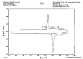
도 1a 및 도 1b는 2가지 솔더 조성물 용융의 시차 주사 열량 측정 (DSC) 자취를 보여준다 (샘플 크기: 각각 29.1000㎎ 및 29.3000㎎; 기구: 2920 DSC V2.6A). 첫번째는 20% SAC 및 80% Sn58Bi의 혼합물이다. 두번째는 Sn45Bi이다. SAC가 217℃의 용융 온도를 가지지만, 이들 자취는 유사하다. SAC는 SAC의 용융 온도보다 훨씬 낮은 Sn58Bi에 잘 용해된다. 동시에 제 1 혼합물은 Sn58Bi 단독보다 볼 전단 시험에서 현저히 더 높은 전단력을 보여주는 것으로 밝혀졌다 (949 대 911). DSC 자취를 17.1% Sn58Bi 및 82.9% Sn0.3Ag0.7Cu0.1Bi (SACX0307)의 혼합물에 대하여도 또한, 얻었다. 초기 주사는 SnBi 합금의 용융에 상응하는 저온 피크를 보여 주었다. 그러나, 이 피크는, 액체 Sn58Bi에 SACX0307을 용해시킴으로써 모든 저온 상이 고온 상으로 변환되는 것을 나타내는 이후의 주사에서 사라졌다.Figures 1a and 1b show differential scanning calorimetry (DSC) traces of two solder composition melts (sample size: 29.1000 mg and 29.3000 mg, respectively; instrument: 2920 DSC V2.6A). The first is a mixture of 20% SAC and 80% Sn58Bi. The second is Sn45Bi. SAC has a melting temperature of 217 ° C, but these traces are similar. SAC is well soluble in Sn58Bi, which is much lower than the melting temperature of SAC. At the same time, the first mixture was found to show significantly higher shear forces in ball shear tests than Sn58Bi alone (949 vs. 911). The DSC trace was also obtained for a mixture of 17.1% Sn58Bi and 82.9% Sn0.3Ag0.7Cu0.1Bi (SACX0307). The initial injection showed a low temperature peak corresponding to the melting of the SnBi alloy. However, this peak disappeared in subsequent injections indicating that all the low temperature phase was converted to the high temperature phase by dissolving SACX0307 in liquid Sn58Bi.
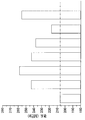
도 2a 및 도 2b는 나노 또는 마이크로 크기의 Ag 입자의 첨가시 SnBi의 탄성률 개선을 나타낸다. 도 2a에서, 입자는 20 나노미터 내지 1 미크론의 평균 입자 크기를 가지는 나노 크기의 입자이다. 도 2b에서, Ag 입자는 그 크기가 1 미크론 내지 100 미크론이다. 알 수 있는 바와 같이, 심지어 소량 (1%)의 Ag 입자라도 탄성률에 현저한 영향을 미치는 것으로 밝혀졌다. 은 입자의 첨가는 솔더의 열 및 전기 전도성을 개선시킨다. Sn58Bi 솔더의 유리 (free) 은 입자의 존재는 놀랍게도 그것의 열 전도성을 50% 보다 더 증가시키는 것으로 밝혀졌다. 더욱이, 은 첨가는 합금의 미세 구조를 변화시킨다. 심지어 5%까지의 Ag 첨가는 놀랍게도 긴 Ag3Sn 결정을 초래하지 않는 것으로 밝혀졌다. 도 2a에서, 탄성률 값은 다음의 솔더에 대해 나타낸 것이다 (왼쪽에서 오른쪽으로): Sn58Bi, Sn58Bi + 1% 나노 크기 Ag의 혼합물, Sn58Bi + 3% 나노 크기 Ag의 혼합물 및 Sn58Bi + 5% 나노 크기 Ag의 혼합물. 도 2b에서, 탄성률 값은 다음의 솔더에 대해 나타낸 것이다 (왼쪽에서 오른쪽으로): Sn58Bi, Sn58Bi + 1% 미크론 크기 (1 내지 100 미크론) Ag의 혼합물, Sn58Bi + 3% 미크론 크기 Ag의 혼합물 및 Sn58Bi + 5% 미크론 크기 Ag의 혼합물.2A and 2B show the improvement in the modulus of SnBi when nano- or micro-sized Ag particles are added. In Figure 2a, the particles are nanosized particles having an average particle size of 20 nanometers to 1 micron. In Fig. 2B, Ag particles are 1 micron to 100 microns in size. As can be seen, even small amounts (1%) of Ag particles have been found to have a significant impact on the modulus of elasticity. The addition of silver particles improves the heat and electrical conductivity of the solder. Free of Sn58Bi solder, the presence of particles surprisingly proved to increase its thermal conductivity by more than 50%. Moreover, the addition of silver changes the microstructure of the alloy. It has been found that even up to 5% Ag addition does not result in surprisingly long Ag 3 Sn crystals. In Figure 2a, the modulus values are shown for the following solders (from left to right): Sn58Bi, a mixture of Sn58Bi + 1% nano-sized Ag, a mixture of Sn58Bi + 3% nano-sized Ag, and a mixture of Sn58Bi + 5% / RTI > 2b, the elastic modulus values are shown for the following solders (from left to right): Sn58Bi, a mixture of Sn58Bi + 1% micron size (1 to 100 micron) Ag, a mixture of Sn58Bi + 3% + 5% micron size Ag.
도 3은 표준 Sn58Bi 솔더 (좌측)의 전단 강도 및 본 발명에 따른 솔더 조성물 (Sn58Bi+20% SAC305)의 전단 강도를 비교한 것을 보여준다. Sn58Bi 파우더에 SAC305 파우더를 첨가함으로써, 리플로우 후 더 낮은 Bi를 갖는 최종 조성물을 야기시키고, 또한 더 높은 전단 강도를 보여준다.3 shows a comparison between the shear strength of the standard Sn58Bi solder (left) and the shear strength of the solder composition (Sn58Bi + 20% SAC305) according to the present invention. The addition of SAC305 powder to the Sn58Bi powder results in a final composition with lower Bi after reflow and also shows a higher shear strength.
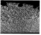
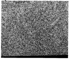
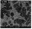
도 4a 내지 도 4c는 본 명세서에 설명된 많은 솔더 조성물의 결정 구조를 보여주는 다양한 현미경 사진을 보여준다. 도 4a 및 도 4b는 각각 Al2O3을 첨가한 Sn45Bi 및 Sn58Bi 합금의 미세 구조를 각각 보여준다. 각각의 경우에서, 알루미늄 파우더를, 구리 절취 시편에 인쇄된 페이스트 플럭스에 첨가하였다. Sn45Bi 및 Sn58Bi의 얇은 프리폼을 플럭스 상에 두었다. 핫 플레이트 상에서 185℃에서 가열하고, 공기 중에서 냉각하였다. 알루미늄 입자의 솔더로의 확산으로 인해, 솔더의 미세 구조는 계면 근처에서 두드러지게 정제된다.Figures 4A-4C show various micrographs showing the crystal structure of many of the solder compositions described herein. Figures 4a and 4b each shows the microstructure of Sn45Bi and Sn58Bi alloy with addition of Al 2 O 3, respectively. In each case, aluminum powder was added to the paste flux printed on the copper cut specimen. A thin preform of Sn45Bi and Sn58Bi was placed on the flux. Heated on a hot plate at 185 占 폚 and cooled in air. Due to the diffusion of aluminum particles into the solder, the microstructure of the solder is significantly refined near the interface.
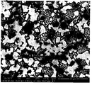
도 4c는 구리 입자를 갖는 Sn58Bi 합금의 현미경 사진을 보여준다. 알 수 있는 바와 같이, 구리 입자는 SnBi 합금 매트릭스에 균일하게 분산된다. CuSn IMC층이 입자의 표면에서 보이지만, 입자의 대부분은 순수한 구리이다.Figure 4c shows a micrograph of Sn58Bi alloy with copper particles. As can be seen, the copper particles are uniformly dispersed in the SnBi alloy matrix. The CuSn IMC layer is visible on the surface of the particles, but most of the particles are pure copper.
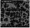
도 5a 및 도 5b는 Sn45Bi 솔더 합금에 니켈을 첨가한 것을 증명한다. 도 5a에서, 존재하는 Ni은 없다. 도 5b에서, 0.02 Ni을 포함하고, 이것은 현저한 입자 정제 효과를 갖는다.Figures 5A and 5B demonstrate the addition of nickel to the Sn45Bi solder alloy. In Figure 5A, there is no Ni present. In Figure 5b, it contains 0.02 Ni, which has a significant particle refining effect.
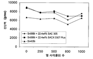
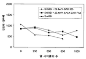
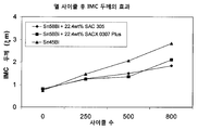
도 6a, 도 6b 및 도 6c는 Sn58Bi + 22.4wt% SAC305의 혼합물 (다이아몬드), Sn58Bi + 22.4wt% SACX0307의 혼합물 (사각형) 및 Sn45Bi (삼각형)에 대하여, 열 사이클 동안의 전단력 (6a), 인장력 (6b) 및 금속간 화합물 (IMC) 성장 (6c)의 변화를 나타낸다. 열 사이클의 조건은 -40 내지 125℃, 10분의 체류 시간 및 1000 사이클이었다. 도 6a 및 도 6b는 본 발명의 솔더의 전단력 및 인장력 (납의 당김 저항)의 값이 열 사이클 후에 상기 Sn45Bi 보다 덜 감소하는 것을 나타낸다. 도 6c는 열 사이클 동안의 IMC 성장이 Sn45Bi에 비해 본 발명의 솔더가 훨씬 더 낮음을 나타내며, 본 발명의 솔더에 대한 훨씬 우수한 솔더 조인트 신뢰성을 나타낸다.6A, 6B and 6C show shear force 6a, tensile force (tensile force) during thermal cycling for a mixture (diamond) of Sn58Bi + 22.4wt% SAC305, a mixture (square) of Sn58Bi + 22.4wt% SACX0307 and Sn45Bi (6b) and intermetallic compound (IMC) growth (6c). The conditions of the thermal cycle were -40 to 125 캜, a residence time of 10 minutes, and 1000 cycles. Figures 6A and 6B show that the values of shear force and tensile force (pulling resistance of lead) of the solder of the present invention are less than Sn45Bi after thermal cycling. FIG. 6C shows that the IMC growth during the thermal cycle shows much less solder of the present invention compared to Sn45Bi and represents a much better solder joint reliability for the solder of the present invention.
도 7은 Sn58Bi + SAC305의 혼합물 (원) 및 Sn45Bi (사각형)에 대한 내충격 강하 데이터를 보여준다. Sn58Bi + SAC305의 혼합물의 내충격 강하 (결함에 대한 평균 강하 수: 200.3)는 Sn45Bi의 내충격 강하 (결함에 대한 평균 강하 수: 167.2)에 비해 분명히 더 높다.Figure 7 shows the impact resistance data for a mixture (circle) of Sn58Bi + SAC305 and Sn45Bi (square). The impact resistance (average drop number to defect: 200.3) of the mixture of Sn58Bi + SAC305 is clearly higher than that of Sn45Bi (average drop number to defect: 167.2).
도 8a는 합금에 대한 전단 강도 값을 증명한다 (왼쪽에서 오른쪽으로): Sn58Bi (캐스트로서), Sn58Bi (캐스팅 후 48시간), Sn58Bi + 1 wt% 미크론 크기 Ag 입자의 혼합물 (캐스팅 후 48시간), Sn58Bi + 3 wt% 미크론 크기 Ag 입자의 혼합물 (캐스팅 후 48시간), Sn58Bi + 1 wt% 미크론 크기 Ag 코팅된 Cu 입자의 혼합물 (캐스팅 후 48시간), Sn58Bi + 3 wt% 미크론 크기 Ag 코팅된 Cu 입자의 혼합물 (캐스팅 후 48시간) 및 Sn58Bi + 5 wt% 미크론 크기 Ag 코팅된 Cu 입자의 혼합물 (캐스팅 후 48시간). Ag의 첨가로 에이징의 결과로 손실되는 전단 강도가 회복된다 (3 wt% Ag 입자에 대해 14.6% 증가).8a shows a shear strength value for the alloy (from left to right): Sn58Bi (as cast), Sn58Bi (48 hours after casting), Sn58Bi + 1 wt% , Sn58Bi + 3 wt% Ag particles (48 hours after casting), Sn58Bi + 1 wt% Ag coated Cu particles (48 hours after casting), Sn58Bi + 3 wt% A mixture of Cu particles (48 hours after casting) and a mixture of Sn particles coated with Sn58Bi + 5 wt% micron size Ag (48 hours after casting). Addition of Ag restores the shear strength lost as a result of aging (14.6% increase over 3 wt% Ag particles).
도 8b는 합금에 대한 경도 값을 증명한다 (왼쪽에서 오른쪽으로): Sn58Bi, Sn58Bi + 1 wt% 미크론 크기 Ag 입자의 혼합물, Sn58Bi + 3 wt% 미크론 크기 Ag 입자의 혼합물, Sn58Bi + 5 wt% 미크론 크기 Ag 입자의 혼합물, Sn58Bi + 1 wt% 나노미터 크기 Ag 입자의 혼합물, Sn58Bi + 3 wt% 나노미터 크기 Ag 입자의 혼합물 및 Sn58Bi + 5 wt% 나노미터 크기 Ag 입자의 혼합물. 경도는 3 wt% 미크론 크기 Ag 입자의 첨가로 25%까지 증가한다.Figure 8b demonstrates the hardness value for the alloy (from left to right): Sn58Bi, Sn58Bi + 1 wt% Mixture of Ag particles in micron size, Mixture of Sn58Bi + 3 wt% Ag particles in Sn58Bi + 5 wt% Mixture of Ag particles of
본 발명에서 청구하는 조성물은 LED 조립, 태양 전지 태빙 (tabbing) 및 가선 (stringing), 반도체 말미 공정 및 다이 부착을 포함하는 적용 분야에 유용하지만, 이것들로 한정되는 것은 아니다. 최종 형태 인자는 적용 분야에 의존하지만, 솔더는 페이스트, 프리폼, 필름 및 와이어를 포함하는 어떠한 형태로도 만들어질 수 있지만, 이것들로 한정되는 것은 아니며, 세정 가능한 또는 무-세정 플럭스 화합물과 조합될 수 있다.The compositions claimed in the present invention are useful in applications including, but not limited to, LED assembly, solar cell tabbing and stringing, semiconductor end milling and die attach. The final form factor depends on the field of application, but the solder can be made in any form including paste, preform, film and wire, but is not limited to this and can be combined with a cleanable or no-clean flux compound have.
본 발명의 요소 또는 본 발명의 바람직한 실시형태를 도입할 때에, 관사 "하나의 (a)", "하나의 (an)", "그 (the)" 및 "상기 (said)"는 하나 또는 그 이상의 요소가 있다는 것을 의미하고자 한다. "포함하는 (comprising)", "포함하는 (including)" 및 "가지는 (having)"이란 용어는 포괄시키고자 하는 것이며, 나열된 요소 이외의 추가 요소가 있을 수 있다는 것을 의미하도록 하기 위한 것이다.In introducing elements of the invention or the preferred embodiments of the invention, the articles "a", "an", "the" and "said" We want to mean that there are more elements. The terms "comprising," "including," and "having" are intended to be inclusive and mean that there may be additional elements other than the listed elements.
전술한 상세한 설명은 설명 및 도시의 방식으로 제공되며, 첨부된 특허청구범위의 범위를 제한하려는 것은 아니다. 본 명세서에 도시된 본 발명의 바람직한 실시형태에서의 많은 변형이 당업자에게 명백할 것이며, 첨부된 특허청구범위 및 그 등가물의 범위 내에 있다.The foregoing detailed description is provided by way of illustration and example, and is not intended to limit the scope of the appended claims. Many modifications in the preferred embodiments of the invention shown and described herein will be apparent to those skilled in the art and are within the scope of the appended claims and their equivalents.
Claims (25)
상기 솔더 조성물이 제 1 파우더 성분 및 제 2 파우더 성분의 블렌드와 함께 불가피 불순물로 이루어진 솔더 조성물.The method according to claim 1,
Wherein the solder composition is comprised of inevitable impurities along with a blend of the first powder component and the second powder component.
상기 솔더 조성물이 무연 (lead-free)인 솔더 조성물. 3. The method according to claim 1 or 2,
Wherein the solder composition is lead-free.
상기 제 1 솔더 합금 및 제 2 솔더 합금은 적어도 하나의 공통된 원소를 포함하는 솔더 조성물.4. The method according to any one of claims 1 to 3,
Wherein the first solder alloy and the second solder alloy comprise at least one common element.
상기 적어도 하나의 공통된 원소는 주석인 솔더 조성물.5. The method of claim 4,
Wherein the at least one common element is tin.
상기 제 1 솔더 합금 및 제 2 솔더 합금은 상이한 용융점을 가지는 솔더 조성물.6. The method according to any one of claims 1 to 5,
Wherein the first solder alloy and the second solder alloy have different melting points.
상기 용융점은 적어도 5℃ 만큼 상이한 솔더 조성물.The method according to claim 6,
Wherein the melting point is different by at least 5 < 0 > C.
상기 제 1 파우더 성분은 솔더 조성물의 약 80 중량%를 형성하고 42Sn 58Bi이며, 상기 제 2 파우더 조성물은 솔더 조성물의 약 20 중량%를 형성하고 SAC305 (96.5% Sn, 0.5% Cu, 3% Ag)인 솔더 조성물.8. The method according to any one of claims 1 to 7,
The first powder component forms about 80% by weight of the solder composition and is 42Sn58Bi, and the second powder composition forms about 20% by weight of the solder composition and comprises SAC305 (96.5% Sn, 0.5% Cu, 3% Ag) Lt; / RTI >
상기 금속은 Cu, Ag, Al, Au, Cr, In, Sb, Sc, Y, Zn, Ce, Co, Ge, Mn, Ni 및 Ti 또는 희토류 원소로부터 선택되는 원소인 솔더 조성물.4. The method according to any one of claims 1 to 3,
Wherein the metal is an element selected from Cu, Ag, Al, Au, Cr, In, Sb, Sc, Y, Zn, Ce, Co, Ge, Mn, Ni and Ti or a rare earth element.
상기 금속 입자는 (i) 1nm 내지 100 미크론; 또는 (ii) 10nm 내지 100 미크론; 또는 (iii) 100 미크론 내지 1000 미크론인 솔더 조성물.10. The method of claim 9,
(I) 1 nm to 100 microns; Or (ii) 10 nm to 100 microns; Or (iii) 100 microns to 1000 microns.
제 1 솔더 합금 및 제 2 솔더 합금은 유사한 용융 온도를 가지며, 혼화되지 않는 솔더 조성물.4. The method according to any one of claims 1 to 3,
The first solder alloy and the second solder alloy have a similar melting temperature and are not miscible.
상기 제 1 솔더 합금 및 제 2 솔더 합금의 용융 온도는 10℃인 솔더 조성물.12. The method of claim 11,
Wherein the melting temperature of the first solder alloy and the second solder alloy is 10 占 폚.
상기 제 1 솔더 합금의 열 팽창 계수는 양 (plus)이고, 상기 제 2 솔더 합금의 열 팽창 계수는 음 (minus)인 솔더 조성물.13. The method according to claim 11 or 12,
Wherein the coefficient of thermal expansion of the first solder alloy is positive and the coefficient of thermal expansion of the second solder alloy is minus.
상기 제 2 파우더 성분은 비반응성 코팅층을 가지는 솔더 조성물.14. The method according to any one of claims 11 to 13,
Wherein the second powder component has a non-reactive coating layer.
탄화물, 질화물, 산화물 또는 탄소 나노튜브로부터 선택되고, 바람직하게는 Al2O3, SiO2, TiO, NiO 및 탄소 나노튜브로부터 선택되는 추가의 파우더 성분을 더 포함하는 솔더 조성물.15. The method according to any one of claims 1 to 14,
Wherein the solder composition further comprises an additional powder component selected from carbides, nitrides, oxides or carbon nanotubes and preferably selected from Al 2 O 3 , SiO 2 , TiO 2 , NiO and carbon nanotubes.
상기 제 1 파우더 성분은 페이스트의 형태이고, 제 2 파우더 성분은 프리폼, 스트립, 슬리브, 디스크, 구 또는 와이어의 형태인 방법.19. The method of claim 18,
Wherein the first powder component is in the form of a paste and the second powder component is in the form of a preform, strip, sleeve, disc, sphere or wire.
(ii) 제 1 리플로우 온도를 가지는 제 1 솔더 성분을 제공하는 단계;
(iii) 상기 제 1 리플로우 온도보다 높은 제 2 리플로우 온도를 가지는 제 2 솔더 성분을 제공하는 단계; 및
(iv) 상기 제 1 솔더 성분 및 제 2 솔더 성분을 접합되는 워크 피스의 근처에서 가열하는 단계로서, 상기 가열은 제 1 리플로우 온도보다 높거나 또는 그 온도에서, 그리고 제 2 리플로우 온도 미만에서 수행되는 단계를 포함하는 솔더 조인트의 형성 방법.(i) providing two or more workpieces to be joined;
(ii) providing a first solder component having a first reflow temperature;
(iii) providing a second solder component having a second reflow temperature higher than the first reflow temperature; And
(iv) heating the first solder component and the second solder component in the vicinity of the workpiece to be bonded, wherein the heating is performed at a temperature higher than or at the first reflow temperature and at a temperature below the second reflow temperature Wherein the step of forming the solder joint comprises:
Applications Claiming Priority (3)
| Application Number | Priority Date | Filing Date | Title |
|---|---|---|---|
| US201161514396P | 2011-08-02 | 2011-08-02 | |
| US61/514,396 | 2011-08-02 | ||
| PCT/GB2012/051876 WO2013017885A2 (en) | 2011-08-02 | 2012-08-02 | Solder compositions |
Publications (1)
| Publication Number | Publication Date |
|---|---|
| KR20140063662A true KR20140063662A (en) | 2014-05-27 |
Family
ID=46826859
Family Applications (1)
| Application Number | Title | Priority Date | Filing Date |
|---|---|---|---|
| KR1020147005657A KR20140063662A (en) | 2011-08-02 | 2012-08-02 | Solder compositions |
Country Status (11)
| Country | Link |
|---|---|
| US (1) | US20140199115A1 (en) |
| EP (2) | EP3766631A3 (en) |
| JP (3) | JP2014527466A (en) |
| KR (1) | KR20140063662A (en) |
| CN (2) | CN112355513A (en) |
| BR (1) | BR112014002359A2 (en) |
| CA (1) | CA2842762A1 (en) |
| IN (1) | IN2014CN00939A (en) |
| MX (1) | MX2014001204A (en) |
| RU (1) | RU2627822C2 (en) |
| WO (1) | WO2013017885A2 (en) |
Cited By (1)
| Publication number | Priority date | Publication date | Assignee | Title |
|---|---|---|---|---|
| KR20160027453A (en) * | 2014-08-29 | 2016-03-10 | 한국기계연구원 | Hybrid Composite Solder Alloys and Their Fabrication Methods |
Families Citing this family (45)
| Publication number | Priority date | Publication date | Assignee | Title |
|---|---|---|---|---|
| US9272371B2 (en) * | 2013-05-30 | 2016-03-01 | Agc Automotive Americas R&D, Inc. | Solder joint for an electrical conductor and a window pane including same |
| WO2015083661A1 (en) * | 2013-12-03 | 2015-06-11 | 国立大学法人広島大学 | Solder material and joining structure |
| JP6338419B2 (en) * | 2014-03-28 | 2018-06-06 | 新日鉄住金化学株式会社 | Metal particle composition, bonding material, and bonding method using the same |
| JP2015208765A (en) * | 2014-04-28 | 2015-11-24 | 三菱電機株式会社 | Unleaded solder material, semiconductor device for electric power, and method of manufacturing semiconductor device for electric power |
| WO2015198497A1 (en) * | 2014-06-24 | 2015-12-30 | ハリマ化成株式会社 | Solder alloy, solder paste and electronic circuit board |
| KR101671062B1 (en) | 2014-08-18 | 2016-10-31 | 주식회사 경동원 | Lead-free solder composition and manufacturing method of lead-free solder composition |
| US10563292B2 (en) * | 2015-04-09 | 2020-02-18 | Electronics And Telecommunications Research Institute | Metal material for 3-dimensional printing, method for manufacturing the same, and method for 3-dimensional printing using the same |
| CN105161482A (en) * | 2015-06-26 | 2015-12-16 | 江苏师范大学 | Interconnection material for stacking of three-dimensional packaging chips |
| US10518362B2 (en) * | 2015-07-24 | 2019-12-31 | Harima Chemicals, Incorporated | Solder alloy, solder paste, and electronic circuit board |
| CN105140210B (en) * | 2015-08-06 | 2018-02-13 | 江苏师范大学 | A kind of chip-stacked interconnection material containing Pr, sub-micron TiN |
| CN105185770A (en) * | 2015-08-06 | 2015-12-23 | 江苏师范大学 | 3D chip stacking and interconnection material containing Er and nano-Al |
| CN105185768B (en) * | 2015-08-06 | 2018-08-17 | 江苏师范大学 | A kind of interconnection material containing Ce, nano Co that 3D chips stack |
| CN105185767B (en) * | 2015-08-06 | 2018-08-17 | 江苏师范大学 | Three-dimension packaging chip containing La, Ni nanoparticle stacks interconnection material |
| CN105047248A (en) * | 2015-08-06 | 2015-11-11 | 江苏师范大学 | Chip stacking interconnected material containing Lu and carbon nano tube |
| CN105161483A (en) * | 2015-08-06 | 2015-12-16 | 江苏师范大学 | Interconnection material containing Yb and namometer Cu and formed by stacking of 3D chips |
| CN105177387B (en) * | 2015-08-06 | 2017-03-15 | 江苏师范大学 | A kind of chip-stacked interconnection materials containing Eu, nanometer Au of 3D |
| CN105552201B (en) * | 2015-12-09 | 2018-11-30 | 北京大学深圳研究生院 | A kind of LED encapsulation die bond material and preparation method thereof |
| CN106011515B (en) * | 2016-06-20 | 2017-12-12 | 山东建筑大学 | A kind of method for preparing carbon nanotube powder enhancing leypewter |
| CN107052613A (en) * | 2016-11-30 | 2017-08-18 | 安徽华众焊业有限公司 | Low-melting point leadless solder and preparation method thereof |
| CN106736016A (en) * | 2016-11-30 | 2017-05-31 | 安徽华众焊业有限公司 | Cadmium-free low-silver medium-temperature solder for welding hard alloy and steel |
| CN106624431A (en) * | 2016-11-30 | 2017-05-10 | 安徽华众焊业有限公司 | Tin-zinc lead-free solder and preparation method thereof |
| CN107058784B (en) * | 2017-01-12 | 2018-09-11 | 哈尔滨工业大学 | The preparation method of CNTs-Sn solder with composite material for tin-coated welding strip |
| US10263362B2 (en) | 2017-03-29 | 2019-04-16 | Agc Automotive Americas R&D, Inc. | Fluidically sealed enclosure for window electrical connections |
| US10849192B2 (en) | 2017-04-26 | 2020-11-24 | Agc Automotive Americas R&D, Inc. | Enclosure assembly for window electrical connections |
| JP7145855B2 (en) * | 2017-11-22 | 2022-10-03 | 深▲チェン▼市福英達工業技術有限公司 | Micro/nanoparticle reinforced composite solder and its preparation method |
| CN108838541B (en) * | 2018-09-14 | 2020-07-24 | 苏州大学 | Laser welding method and welding joint of cold-rolled steel plate for automobile |
| JP6811798B2 (en) * | 2018-09-28 | 2021-01-13 | 株式会社タムラ製作所 | Molded solder and manufacturing method of molded solder |
| CN110961831B (en) * | 2018-09-28 | 2022-08-19 | 株式会社田村制作所 | Forming solder and manufacturing method of forming solder |
| FR3087369B1 (en) * | 2018-10-19 | 2021-06-04 | Dehon Sa | SOLDERING ALLOY AND USE OF SUCH ALLOY |
| JP2022506217A (en) * | 2018-10-31 | 2022-01-17 | ローベルト ボツシユ ゲゼルシヤフト ミツト ベシユレンクテル ハフツング | Mixed alloy solder paste, its manufacturing method, and soldering method |
| CN109759740A (en) * | 2018-12-21 | 2019-05-17 | 广东中实金属有限公司 | A kind of high thermal conductivity solder suitable for power semiconductor device package |
| CN109742196A (en) * | 2018-12-22 | 2019-05-10 | 中智(泰兴)电力科技有限公司 | A kind of low-temperature welding method of monocrystalline silicon heterojunction solar cell |
| CN109671639B (en) * | 2018-12-25 | 2020-10-23 | 苏州腾晖光伏技术有限公司 | Method for testing reliability of battery metal electrode and welding strip after welding |
| KR102187085B1 (en) * | 2019-01-24 | 2020-12-04 | 주식회사 경동엠텍 | lead-free solder composition for high-temperature and vibrational circumstance and manufacturing method thereof |
| US11267080B2 (en) | 2019-05-09 | 2022-03-08 | Indium Corporation | Low temperature melting and mid temperature melting lead-free solder paste with mixed solder alloy powders |
| JPWO2021045131A1 (en) * | 2019-09-02 | 2021-03-11 | ||
| CN110508973B (en) * | 2019-09-11 | 2021-07-06 | 重庆群崴电子材料有限公司 | High-temperature service soldering paste realized by doping nano particles and preparation method thereof |
| JP7226280B2 (en) * | 2019-11-29 | 2023-02-22 | 株式会社三洋物産 | game machine |
| JP7226277B2 (en) * | 2019-11-29 | 2023-02-22 | 株式会社三洋物産 | game machine |
| JP7226279B2 (en) * | 2019-11-29 | 2023-02-22 | 株式会社三洋物産 | game machine |
| JP7226276B2 (en) * | 2019-11-29 | 2023-02-22 | 株式会社三洋物産 | game machine |
| CN111590235B (en) * | 2020-06-11 | 2022-04-01 | 中山翰华锡业有限公司 | Low-dielectric-loss high-reliability soldering paste and preparation method thereof |
| CN113172291B (en) * | 2021-04-09 | 2022-06-03 | 哈尔滨工业大学 | Preparation method of low-temperature high-strength connecting welding spot in PoP packaging process |
| CN113231757A (en) * | 2021-06-22 | 2021-08-10 | 内蒙古玉桥合金材料制造有限公司 | Tin-based soldering paste and preparation method thereof |
| US20230241725A1 (en) * | 2022-01-19 | 2023-08-03 | Ning-Cheng Lee | Solder pastes and methods of using the same |
Family Cites Families (31)
| Publication number | Priority date | Publication date | Assignee | Title |
|---|---|---|---|---|
| US2950184A (en) * | 1957-06-06 | 1960-08-23 | Glidden Co | Process for preparing powdered silversolder compositions |
| JPS5223531A (en) * | 1975-08-18 | 1977-02-22 | Nissan Motor | Abrasionnresistant sliding member and its production method |
| JPH0585850A (en) * | 1991-09-30 | 1993-04-06 | Murata Mfg Co Ltd | Solder paste for joining aluminum nitride substrate to copper plate |
| US5569433A (en) | 1994-11-08 | 1996-10-29 | Lucent Technologies Inc. | Lead-free low melting solder with improved mechanical properties |
| US5928404A (en) * | 1997-03-28 | 1999-07-27 | Ford Motor Company | Electrical solder and method of manufacturing |
| JPH11186712A (en) * | 1997-12-24 | 1999-07-09 | Nissan Motor Co Ltd | Solder paste and connecting method |
| JPH11347784A (en) * | 1998-06-01 | 1999-12-21 | Victor Co Of Japan Ltd | Soldering paste and electronic circuit using the same |
| JP4315527B2 (en) * | 1999-06-30 | 2009-08-19 | 富士通株式会社 | Solder paste |
| CA2298158C (en) | 2000-02-07 | 2008-04-15 | Itf Optical Technologies Inc.-Technologies Optiques Itf Inc. | Bonding optical fibers to substrates |
| JP4389331B2 (en) * | 2000-03-23 | 2009-12-24 | ソニー株式会社 | Paste solder |
| EP1289707A1 (en) * | 2000-05-24 | 2003-03-12 | Stephen F. Corbin | Variable melting point solders and brazes |
| JP2002001573A (en) * | 2000-06-16 | 2002-01-08 | Nippon Handa Kk | Leadless cream solder and bonding method using the same |
| DK1333957T3 (en) * | 2000-11-16 | 2005-06-20 | Singapore Asahi Chemical & Solder Ind Pte Ltd | Lead-free solder |
| JP3736452B2 (en) * | 2000-12-21 | 2006-01-18 | 株式会社日立製作所 | Solder foil |
| AU2002216373A1 (en) * | 2000-12-21 | 2002-07-01 | Hitachi Ltd. | Solder foil and semiconductor device and electronic device |
| JP3782743B2 (en) * | 2002-02-26 | 2006-06-07 | Tdk株式会社 | Solder composition, soldering method and electronic component |
| JP4095495B2 (en) * | 2003-06-12 | 2008-06-04 | 株式会社東芝 | Solder material, solder material manufacturing method and soldering method |
| JP2005319470A (en) * | 2004-05-06 | 2005-11-17 | Katsuaki Suganuma | Lead-free solder material, electronic circuit board and their production method |
| JP2006326598A (en) * | 2005-05-23 | 2006-12-07 | Harima Chem Inc | Leadless solder paste composition, soldering method, and method for stabilizing joining of electronic component |
| JP4799997B2 (en) | 2005-10-25 | 2011-10-26 | 富士通株式会社 | Method for manufacturing printed circuit board for electronic device and electronic device using the same |
| US20070227627A1 (en) * | 2006-03-30 | 2007-10-04 | Daewoong Suh | Solder composition having dispersoid particles for increased creep resistance |
| JP4385061B2 (en) * | 2006-08-28 | 2009-12-16 | ハリマ化成株式会社 | Solder paste composition and use thereof |
| US10123430B2 (en) | 2006-10-17 | 2018-11-06 | Alpha Assembly Solutions Inc. | Materials for use with interconnects of electrical devices and related methods |
| US7758916B2 (en) * | 2006-11-13 | 2010-07-20 | Sulzer Metco (Us), Inc. | Material and method of manufacture of a solder joint with high thermal conductivity and high electrical conductivity |
| JP2008300342A (en) * | 2007-06-01 | 2008-12-11 | Taisei Kaken:Kk | Metal solder material containing carbon nanotube, conductive material, and semiconducting material |
| KR20100001761A (en) * | 2008-06-27 | 2010-01-06 | 한국산업기술대학교산학협력단 | Sn-ag-cu solder compositions with addition of bi and manufacturing methods thereof |
| JP5470816B2 (en) * | 2008-11-26 | 2014-04-16 | 富士通株式会社 | Manufacturing method of electronic device |
| CN101653877B (en) * | 2009-08-25 | 2011-08-10 | 深圳市亿铖达工业有限公司 | Nano-enhanced leadless solder and preparation method thereof |
| JP5698447B2 (en) * | 2009-09-08 | 2015-04-08 | 株式会社タムラ製作所 | Solder bonding composition |
| KR101225497B1 (en) * | 2009-11-05 | 2013-01-23 | (주)덕산테코피아 | Conductive paste and the manufacturing method thereof and the electric device comprising thereof |
| CN102107340B (en) * | 2009-12-24 | 2015-10-21 | 汉高股份有限及两合公司 | A kind of paste composition, soldering paste and a kind of scaling powder |
-
2012
- 2012-08-02 RU RU2014107896A patent/RU2627822C2/en active
- 2012-08-02 IN IN939CHN2014 patent/IN2014CN00939A/en unknown
- 2012-08-02 EP EP20181499.3A patent/EP3766631A3/en active Pending
- 2012-08-02 CA CA2842762A patent/CA2842762A1/en not_active Abandoned
- 2012-08-02 BR BR112014002359A patent/BR112014002359A2/en not_active Application Discontinuation
- 2012-08-02 MX MX2014001204A patent/MX2014001204A/en unknown
- 2012-08-02 EP EP12756541.4A patent/EP2739431B1/en active Active
- 2012-08-02 KR KR1020147005657A patent/KR20140063662A/en not_active Application Discontinuation
- 2012-08-02 JP JP2014523398A patent/JP2014527466A/en active Pending
- 2012-08-02 WO PCT/GB2012/051876 patent/WO2013017885A2/en active Application Filing
- 2012-08-02 CN CN202011175225.2A patent/CN112355513A/en active Pending
- 2012-08-02 US US14/236,480 patent/US20140199115A1/en not_active Abandoned
- 2012-08-02 CN CN201280038361.4A patent/CN103842126A/en active Pending
-
2019
- 2019-06-04 JP JP2019104821A patent/JP6912519B2/en active Active
-
2021
- 2021-07-08 JP JP2021113488A patent/JP7135171B2/en active Active
Cited By (1)
| Publication number | Priority date | Publication date | Assignee | Title |
|---|---|---|---|---|
| KR20160027453A (en) * | 2014-08-29 | 2016-03-10 | 한국기계연구원 | Hybrid Composite Solder Alloys and Their Fabrication Methods |
Also Published As
| Publication number | Publication date |
|---|---|
| WO2013017885A3 (en) | 2013-04-11 |
| CA2842762A1 (en) | 2013-02-07 |
| IN2014CN00939A (en) | 2015-04-10 |
| CN112355513A (en) | 2021-02-12 |
| WO2013017885A2 (en) | 2013-02-07 |
| MX2014001204A (en) | 2014-08-22 |
| JP2014527466A (en) | 2014-10-16 |
| JP2021178364A (en) | 2021-11-18 |
| JP6912519B2 (en) | 2021-08-04 |
| BR112014002359A2 (en) | 2017-02-21 |
| JP2019206032A (en) | 2019-12-05 |
| EP2739431B1 (en) | 2020-06-24 |
| RU2014107896A (en) | 2015-09-10 |
| RU2627822C2 (en) | 2017-08-11 |
| EP3766631A3 (en) | 2021-03-24 |
| EP3766631A2 (en) | 2021-01-20 |
| EP2739431A2 (en) | 2014-06-11 |
| CN103842126A (en) | 2014-06-04 |
| JP7135171B2 (en) | 2022-09-12 |
| US20140199115A1 (en) | 2014-07-17 |
Similar Documents
| Publication | Publication Date | Title |
|---|---|---|
| JP7135171B2 (en) | solder composition | |
| JP6072032B2 (en) | High impact toughness solder alloy | |
| JP5067163B2 (en) | Solder paste and solder joint | |
| EP2868424B1 (en) | Solder alloy, solder paste, and electronic circuit board | |
| KR101820986B1 (en) | Mixed alloy solder paste | |
| US20160368103A1 (en) | Alternative compositions for high temperature soldering applications | |
| EP2868423A1 (en) | Solder alloy, solder paste, and electronic circuit board | |
| KR20230153507A (en) | Lead-free solder compositions | |
| US20150246417A1 (en) | Mixed alloy solder paste | |
| JP3991788B2 (en) | Solder and mounted product using it | |
| JP2023524690A (en) | Lead-free solder paste for high temperature applications with mixed solder powders | |
| KR20050094535A (en) | Lead-free alloys of low temperature | |
| Muktadir Billah | Effect of Reinforcements on the Structure and Properties of Lead Free Tin Zinc Alloys |
Legal Events
| Date | Code | Title | Description |
|---|---|---|---|
| AMND | Amendment | ||
| A201 | Request for examination | ||
| AMND | Amendment | ||
| E902 | Notification of reason for refusal | ||
| AMND | Amendment | ||
| E601 | Decision to refuse application | ||
| E601 | Decision to refuse application | ||
| E801 | Decision on dismissal of amendment |