KR20140015704A - In-wheel motor and in-wheel working device - Google Patents
In-wheel motor and in-wheel working device Download PDFInfo
- Publication number
- KR20140015704A KR20140015704A KR1020120076181A KR20120076181A KR20140015704A KR 20140015704 A KR20140015704 A KR 20140015704A KR 1020120076181 A KR1020120076181 A KR 1020120076181A KR 20120076181 A KR20120076181 A KR 20120076181A KR 20140015704 A KR20140015704 A KR 20140015704A
- Authority
- KR
- South Korea
- Prior art keywords
- motor
- rotor
- wheel
- cover
- stator
- Prior art date
Links
- 239000000725 suspension Substances 0.000 claims description 69
- 238000000034 method Methods 0.000 claims description 25
- 239000003638 chemical reducing agent Substances 0.000 claims description 14
- 238000000926 separation method Methods 0.000 claims description 7
- 238000006073 displacement reaction Methods 0.000 claims description 6
- 239000002184 metal Substances 0.000 claims description 6
- 239000000696 magnetic material Substances 0.000 claims description 5
- 230000001360 synchronised effect Effects 0.000 claims description 4
- 238000009434 installation Methods 0.000 description 7
- 239000002803 fossil fuel Substances 0.000 description 3
- 239000000446 fuel Substances 0.000 description 3
- 230000005611 electricity Effects 0.000 description 2
- 238000005516 engineering process Methods 0.000 description 2
- 230000006698 induction Effects 0.000 description 2
- UFHFLCQGNIYNRP-UHFFFAOYSA-N Hydrogen Chemical compound [H][H] UFHFLCQGNIYNRP-UHFFFAOYSA-N 0.000 description 1
- 230000009471 action Effects 0.000 description 1
- 238000004891 communication Methods 0.000 description 1
- 230000008878 coupling Effects 0.000 description 1
- 238000010168 coupling process Methods 0.000 description 1
- 238000005859 coupling reaction Methods 0.000 description 1
- 229910052739 hydrogen Inorganic materials 0.000 description 1
- 239000001257 hydrogen Substances 0.000 description 1
- 230000002452 interceptive effect Effects 0.000 description 1
- 230000007246 mechanism Effects 0.000 description 1
- 230000004048 modification Effects 0.000 description 1
- 238000012986 modification Methods 0.000 description 1
- 230000008569 process Effects 0.000 description 1
- 230000009467 reduction Effects 0.000 description 1
Images


Classifications
-
- B—PERFORMING OPERATIONS; TRANSPORTING
- B60—VEHICLES IN GENERAL
- B60L—PROPULSION OF ELECTRICALLY-PROPELLED VEHICLES; SUPPLYING ELECTRIC POWER FOR AUXILIARY EQUIPMENT OF ELECTRICALLY-PROPELLED VEHICLES; ELECTRODYNAMIC BRAKE SYSTEMS FOR VEHICLES IN GENERAL; MAGNETIC SUSPENSION OR LEVITATION FOR VEHICLES; MONITORING OPERATING VARIABLES OF ELECTRICALLY-PROPELLED VEHICLES; ELECTRIC SAFETY DEVICES FOR ELECTRICALLY-PROPELLED VEHICLES
- B60L50/00—Electric propulsion with power supplied within the vehicle
- B60L50/50—Electric propulsion with power supplied within the vehicle using propulsion power supplied by batteries or fuel cells
-
- H—ELECTRICITY
- H02—GENERATION; CONVERSION OR DISTRIBUTION OF ELECTRIC POWER
- H02K—DYNAMO-ELECTRIC MACHINES
- H02K7/00—Arrangements for handling mechanical energy structurally associated with dynamo-electric machines, e.g. structural association with mechanical driving motors or auxiliary dynamo-electric machines
- H02K7/14—Structural association with mechanical loads, e.g. with hand-held machine tools or fans
-
- B—PERFORMING OPERATIONS; TRANSPORTING
- B60—VEHICLES IN GENERAL
- B60K—ARRANGEMENT OR MOUNTING OF PROPULSION UNITS OR OF TRANSMISSIONS IN VEHICLES; ARRANGEMENT OR MOUNTING OF PLURAL DIVERSE PRIME-MOVERS IN VEHICLES; AUXILIARY DRIVES FOR VEHICLES; INSTRUMENTATION OR DASHBOARDS FOR VEHICLES; ARRANGEMENTS IN CONNECTION WITH COOLING, AIR INTAKE, GAS EXHAUST OR FUEL SUPPLY OF PROPULSION UNITS IN VEHICLES
- B60K7/00—Disposition of motor in, or adjacent to, traction wheel
-
- H—ELECTRICITY
- H02—GENERATION; CONVERSION OR DISTRIBUTION OF ELECTRIC POWER
- H02K—DYNAMO-ELECTRIC MACHINES
- H02K41/00—Propulsion systems in which a rigid body is moved along a path due to dynamo-electric interaction between the body and a magnetic field travelling along the path
- H02K41/02—Linear motors; Sectional motors
- H02K41/03—Synchronous motors; Motors moving step by step; Reluctance motors
- H02K41/031—Synchronous motors; Motors moving step by step; Reluctance motors of the permanent magnet type
-
- B—PERFORMING OPERATIONS; TRANSPORTING
- B60—VEHICLES IN GENERAL
- B60K—ARRANGEMENT OR MOUNTING OF PROPULSION UNITS OR OF TRANSMISSIONS IN VEHICLES; ARRANGEMENT OR MOUNTING OF PLURAL DIVERSE PRIME-MOVERS IN VEHICLES; AUXILIARY DRIVES FOR VEHICLES; INSTRUMENTATION OR DASHBOARDS FOR VEHICLES; ARRANGEMENTS IN CONNECTION WITH COOLING, AIR INTAKE, GAS EXHAUST OR FUEL SUPPLY OF PROPULSION UNITS IN VEHICLES
- B60K17/00—Arrangement or mounting of transmissions in vehicles
- B60K17/04—Arrangement or mounting of transmissions in vehicles characterised by arrangement, location, or kind of gearing
- B60K17/043—Transmission unit disposed in on near the vehicle wheel, or between the differential gear unit and the wheel
- B60K17/046—Transmission unit disposed in on near the vehicle wheel, or between the differential gear unit and the wheel with planetary gearing having orbital motion
-
- B—PERFORMING OPERATIONS; TRANSPORTING
- B60—VEHICLES IN GENERAL
- B60K—ARRANGEMENT OR MOUNTING OF PROPULSION UNITS OR OF TRANSMISSIONS IN VEHICLES; ARRANGEMENT OR MOUNTING OF PLURAL DIVERSE PRIME-MOVERS IN VEHICLES; AUXILIARY DRIVES FOR VEHICLES; INSTRUMENTATION OR DASHBOARDS FOR VEHICLES; ARRANGEMENTS IN CONNECTION WITH COOLING, AIR INTAKE, GAS EXHAUST OR FUEL SUPPLY OF PROPULSION UNITS IN VEHICLES
- B60K7/00—Disposition of motor in, or adjacent to, traction wheel
- B60K2007/0038—Disposition of motor in, or adjacent to, traction wheel the motor moving together with the wheel axle
-
- B—PERFORMING OPERATIONS; TRANSPORTING
- B60—VEHICLES IN GENERAL
- B60K—ARRANGEMENT OR MOUNTING OF PROPULSION UNITS OR OF TRANSMISSIONS IN VEHICLES; ARRANGEMENT OR MOUNTING OF PLURAL DIVERSE PRIME-MOVERS IN VEHICLES; AUXILIARY DRIVES FOR VEHICLES; INSTRUMENTATION OR DASHBOARDS FOR VEHICLES; ARRANGEMENTS IN CONNECTION WITH COOLING, AIR INTAKE, GAS EXHAUST OR FUEL SUPPLY OF PROPULSION UNITS IN VEHICLES
- B60K7/00—Disposition of motor in, or adjacent to, traction wheel
- B60K2007/0092—Disposition of motor in, or adjacent to, traction wheel the motor axle being coaxial to the wheel axle
-
- B—PERFORMING OPERATIONS; TRANSPORTING
- B60—VEHICLES IN GENERAL
- B60K—ARRANGEMENT OR MOUNTING OF PROPULSION UNITS OR OF TRANSMISSIONS IN VEHICLES; ARRANGEMENT OR MOUNTING OF PLURAL DIVERSE PRIME-MOVERS IN VEHICLES; AUXILIARY DRIVES FOR VEHICLES; INSTRUMENTATION OR DASHBOARDS FOR VEHICLES; ARRANGEMENTS IN CONNECTION WITH COOLING, AIR INTAKE, GAS EXHAUST OR FUEL SUPPLY OF PROPULSION UNITS IN VEHICLES
- B60K7/00—Disposition of motor in, or adjacent to, traction wheel
- B60K7/0007—Disposition of motor in, or adjacent to, traction wheel the motor being electric
-
- H—ELECTRICITY
- H02—GENERATION; CONVERSION OR DISTRIBUTION OF ELECTRIC POWER
- H02K—DYNAMO-ELECTRIC MACHINES
- H02K2201/00—Specific aspects not provided for in the other groups of this subclass relating to the magnetic circuits
- H02K2201/15—Sectional machines
-
- H—ELECTRICITY
- H02—GENERATION; CONVERSION OR DISTRIBUTION OF ELECTRIC POWER
- H02K—DYNAMO-ELECTRIC MACHINES
- H02K7/00—Arrangements for handling mechanical energy structurally associated with dynamo-electric machines, e.g. structural association with mechanical driving motors or auxiliary dynamo-electric machines
- H02K7/10—Structural association with clutches, brakes, gears, pulleys or mechanical starters
- H02K7/116—Structural association with clutches, brakes, gears, pulleys or mechanical starters with gears
-
- Y—GENERAL TAGGING OF NEW TECHNOLOGICAL DEVELOPMENTS; GENERAL TAGGING OF CROSS-SECTIONAL TECHNOLOGIES SPANNING OVER SEVERAL SECTIONS OF THE IPC; TECHNICAL SUBJECTS COVERED BY FORMER USPC CROSS-REFERENCE ART COLLECTIONS [XRACs] AND DIGESTS
- Y02—TECHNOLOGIES OR APPLICATIONS FOR MITIGATION OR ADAPTATION AGAINST CLIMATE CHANGE
- Y02T—CLIMATE CHANGE MITIGATION TECHNOLOGIES RELATED TO TRANSPORTATION
- Y02T10/00—Road transport of goods or passengers
- Y02T10/60—Other road transportation technologies with climate change mitigation effect
- Y02T10/64—Electric machine technologies in electromobility
Abstract
Description
본 발명은 인휠 모터 및 인휠 구동장치에 관한 것으로, 휠 내부의 한정된 공간상에 공간효율적으로 탑재할 수 있는 인휠 모터 및 인휠 구동장치에 관한 것이다.
The present invention relates to an in-wheel motor and an in-wheel driving device, and relates to an in-wheel motor and an in-wheel driving device that can be efficiently mounted on a limited space inside the wheel.
화석연료가 고갈되어 감에 따라 휘발유, 경유 등과 같은 화석연료를 사용하는 차량 대신에 배터리에 저장된 전기 에너지를 이용하여 모터를 구동하는 전기 자동차의 개발이 이루어지고 있다.As fossil fuels become depleted, electric vehicles are being developed that use electric energy stored in batteries instead of vehicles using fossil fuels such as gasoline and light oil to drive the motor.
전기 자동차는, 충전 배터리에 저장된 전기 에너지만을 이용하여 모터를 구동하는 순수 전기 차량, 광전지를 이용하여 모터를 구동하는 태양전지 차량, 수소연료를 사용하는 연료전지를 이용하여 모터를 구동하는 연료전지 차량, 화석연료를 이용하여 엔진을 구동하고 전기를 이용하여 모터를 구동함으로써 엔진과 모터를 병용하는 하이브리드 차량 등으로 구분된다.The electric vehicle includes a pure electric vehicle driving a motor using only electric energy stored in a rechargeable battery, a solar battery vehicle driving a motor using a photocell, a fuel cell vehicle driving a motor using a fuel cell using hydrogen fuel , And a hybrid vehicle that uses an engine and a motor by driving an engine using fossil fuel and driving the motor using electricity.
일반적으로, 인휠 구동장치는 전기 자동차와 같이 전기를 동력원으로 사용하는 자동차에 사용되는 기술로서, 가솔린 또는 디젤 자동차에서의 엔진과 미션 및 구동축을 통한 동력 전달에 의해 바퀴가 회전 구동하는 방식과는 달리, 좌우의 구동륜 또는 좌우 및 전후 4개의 구동륜 내부에 배치되는 모터에 의해 동력이 휠에 직접 전달되는 기술이다.
Generally, an in-wheel drive device is a technology used for an automobile that uses electricity as a power source, such as an electric vehicle. Unlike a method in which a wheel is rotated by driving power transmitted through an engine, a mission and a drive shaft in a gasoline or diesel vehicle , And the power is transmitted directly to the wheels by the left and right drive wheels or motors disposed in the right and left and front and rear four drive wheels.
본 발명의 배경기술은 대한민국 공개특허공보 2011-0040459호(2011.04.20 공개, 발명의 명칭: 윈휠 시스템용 차륜구동장치)에 개시되어 있다.
BACKGROUND ART [0002] The background art of the present invention is disclosed in Korean Patent Laid-Open Publication No. 2011-0040459 (published on Apr. 20, 2011, entitled " Wheel Drive System for Winwheel System).
종래의 인휠 모터는 원통형상을 가지며, 이에 따라 휠과 모터 사이에는 원형의 공간부가 형성된다.The conventional in-wheel motor has a cylindrical shape, whereby a circular space portion is formed between the wheel and the motor.
인휠 모터는, 제동장치와 현가장치를 휠과 인휠 모터 사이에 형성된 공간부상에 안정적으로 위치시킬 수 있을 정도의 사이즈를 가져야 하므로, 그 출력을 증가시키는 데 한계가 있다.The in-wheel motor must have a size that can be stably positioned on the space portion formed between the wheel and the in-wheel motor, so that there is a limit in increasing its output.
인휠 모터의 출력을 증가시키기 위해 인휠 모터의 사이즈를 확장시키면, 휠의 사이즈 또한 확장되어야 하는데, 휠의 사이즈(깊이)가 확장되면 현가장치의 암부재가 휠에 쉽게 간섭되어 그 회동이 원활하게 이루어지기 어렵다.If the size of the in-wheel motor is increased to increase the output of the in-wheel motor, the size of the wheel must also be expanded. When the size (depth) of the wheel is expanded, the arm member of the suspension device easily interferes with the wheel, and the rotation thereof is smoothly performed. It is hard to lose.
특히, 전륜에 인휠 모터 적용 시 휠과 조향장치와의 간섭이 추가로 발생하게 된다.In particular, when the in-wheel motor is applied to the front wheel, the interference between the wheel and the steering device is further generated.
본 발명은 상기와 같은 문제점을 개선하기 위해 안출된 것으로서, 휠 내부의 한정된 공간상에 제동장치, 현가장치, 조향장치 등과 함께 공간효율적으로 탑재될 수 있는 인휠 모터 및 인휠 구동장치를 제공하는 것을 목적으로 한다.
An object of the present invention is to provide an in-wheel motor and an in-wheel driving device that can be efficiently installed in a limited space inside the wheel together with a braking device, a suspension device, a steering device, and the like. It is done.
본 발명의 일측면에 따른 인휠 모터는, 차량의 휠 내측에 설치되는 모터회전자; 및 상기 모터회전자의 둘레에 복수개가 이격되게 설치되며, 상기 모터회전자를 회전시키는 자계를 형성하는 모터고정자;를 포함하는 것을 특징으로 한다.In-wheel motor according to an aspect of the present invention, the motor rotor is installed inside the wheel of the vehicle; And a motor stator installed in a plurality of spaced apart around the motor rotor and forming a magnetic field for rotating the motor rotor.
본 발명에서 상기 모터고정자는, 상기 모터회전자의 둘레에 등간격을 두고 배치되는 것을 특징으로 한다.In the present invention, the motor stator, characterized in that arranged at equal intervals around the motor rotor.
본 발명에서 상기 모터고정자는, 상기 모터회전자의 둘레에 대칭을 이루어 배치되는 것을 특징으로 한다.In the present invention, the motor stator is characterized in that the symmetrical arrangement around the motor rotor.
본 발명에서 상기 모터회전자는, 영구자석을 포함하여 구성되며, 상기 모터고정자는, 전자석을 포함하여 구성되는 것을 특징으로 한다.In the present invention, the motor rotor is configured to include a permanent magnet, the motor stator is characterized in that it comprises an electromagnet.
본 발명에서 상기 모터회전자와 상기 모터고정자는, 브러시리스 모터(BLDC Motor, Brushless DC Motor) 또는 영구자석 동기 모터(PMSM, Permanent Magnet Synchronous Motor)를 이루는 것을 특징으로 한다.In the present invention, the motor rotor and the motor stator, characterized in that the brushless motor (BLDC Motor, Brushless DC Motor) or a permanent magnet synchronous motor (PMSM, Permanent Magnet Synchronous Motor).
본 발명에서 상기 모터회전자는, 금속과 같은 자성체를 포함하여 구성되며, 상기 모터고정자는, 전자석을 포함하여 구성되는 것을 특징으로 한다.In the present invention, the motor rotor is configured to include a magnetic material such as metal, and the motor stator is characterized in that it comprises an electromagnet.
본 발명에서 상기 모터회전자와 상기 모터고정자는, 유도전동기 또는 스위치드 릴럭턴스 모터(SRM, Switched Reluctance Motor)를 이루는 것을 특징으로 한다.In the present invention, the motor rotor and the motor stator, characterized in that the induction motor or a switched reluctance motor (SRM, Switched Reluctance Motor) is formed.
본 발명의 일측면에 따른 인휠 구동장치는, 차량의 휠 내측에 설치되는 모터회전자; 상기 모터회전자의 둘레에 복수개가 이격되게 설치되며, 상기 모터회전자를 회전시키는 자계를 형성하는 모터고정자; 상기 모터회전자와 상기 모터고정자를 커버링하는 모터커버; 및 상기 모터고정자 사이에 형성된 이격공간상에서 상기 모터커버에 연결되며, 캘리퍼가 고정설치되는 캘리퍼연결구;를 포함하는 것을 특징으로 한다.In-wheel driving device according to an aspect of the present invention, the motor rotor is installed inside the wheel of the vehicle; A plurality of motor stators spaced apart from each other around the motor rotor and forming a magnetic field for rotating the motor rotor; A motor cover covering the motor rotor and the motor stator; And a caliper connector connected to the motor cover in a space formed between the motor stators, the caliper being fixedly installed.
본 발명에서 상기 모터회전자는, 베어링에 의해 회전가능하게 축지지되는 회전자축; 및 영구자석 또는 금속과 같은 자성체를 포함하여 상기 회전자축의 둘레에 결합되며, 상기 모터고정자에 의해 형성되는 자계의 영향으로 회전되는 자성회전체;를 포함하는 것을 특징으로 한다.The motor rotor in the present invention, the rotor shaft is rotatably supported by the bearing shaft; And a magnetic rotating body coupled to the circumference of the rotor shaft including a magnetic body such as a permanent magnet or a metal and rotated under the influence of a magnetic field formed by the motor stator.
본 발명에서 상기 모터고정자는, 상기 모터회전자의 둘레에 등간격을 두고 배치되는 것을 특징으로 한다.In the present invention, the motor stator, characterized in that arranged at equal intervals around the motor rotor.
본 발명에서 상기 모터고정자는, 상기 모터회전자의 둘레에 대칭을 이루어 배치되는 것을 특징으로 한다.In the present invention, the motor stator is characterized in that the symmetrical arrangement around the motor rotor.
본 발명에서 상기 모터커버는, 상기 모터회전자의 외면부를 커버링하는 회전자커버부; 및 상기 모터고정자의 외면부를 커버링하는 고정자커버부;를 포함하는 것을 특징으로 한다.The motor cover in the present invention, the rotor cover portion for covering the outer surface of the motor rotor; And a stator cover portion covering an outer surface portion of the motor stator.
본 발명에서 상기 회전자커버부는, 내면부가 상기 모터회전자의 외면부로부터 일정한 간극을 가지는 것을 특징으로 한다.In the present invention, the rotor cover portion, characterized in that the inner surface portion has a predetermined gap from the outer surface portion of the motor rotor.
본 발명에서 상기 고정자커버부는, 내면부가 상기 모터고정자의 외면부로부터 일정한 간극을 가지는 것을 특징으로 한다.In the present invention, the stator cover portion, characterized in that the inner surface portion has a predetermined gap from the outer surface portion of the motor stator.
본 발명에서 상기 캘리퍼연결구는, 상기 회전자커버부에 형성되는 것을 특징으로 한다.In the present invention, the caliper connector is formed on the rotor cover.
본 발명에서 상기 모터커버는, 상기 모터회전자와 상기 모터고정자를 내부에 수용가능한 오목한 형상을 가지며, 상기 회전자축의 샤프트부가 관통되는 모터수용부; 및 상기 모터수용부의 개방부를 차폐하며 상기 모터수용부에 결합되는 덮개부;를 포함하는 것을 특징으로 한다.In the present invention, the motor cover has a concave shape that can accommodate the motor rotor and the motor stator therein, the motor accommodating portion through which the shaft portion of the rotor shaft; And a cover part which shields the opening of the motor accommodating part and is coupled to the motor accommodating part.
본 발명에서 상기 모터고정자 사이에 형성된 이격공간상에서 상기 모터커버에 고정설치되며, 현가장치의 단부가 연결되는 현가장치연결구;를 더 포함하는 것을 특징으로 한다.In the present invention is fixed to the motor cover in the separation space formed between the motor stator, the suspension device connector is connected to the end of the suspension device; characterized in that it further comprises.
본 발명에서 상기 캘리퍼연결구는, 상기 모터고정자 사이에 형성되는 복수개의 이격공간 중 일측에 위치되며, 상기 현가장치연결구는, 상기 모터고정자 사이에 형성되는 복수개의 이격공간 중 다른 일측에 위치되는 것을 특징으로 한다.In the present invention, the caliper connector is located on one side of the plurality of separation spaces formed between the motor stator, the suspension connector is located on the other side of the plurality of separation spaces formed between the motor stator. It is done.
본 발명에서 상기 현가장치연결구는, 맥퍼슨 스트럿 서스펜션(MacPherson Strut Suspension)의 로워암(Lower Arm)과 연결되며, 상기 맥퍼슨 스트럿 서스펜션의 스트럿(Strut)은, 상기 모터커버에 고정설치되는 것을 특징으로 한다.In the present invention, the suspension connector is connected to a lower arm of the MacPherson Strut Suspension, the strut of the McPherson Strut Suspension is fixed to the motor cover .
본 발명에서 상기 현가장치연결구는, 멀티링크 서스펜션(Multi-Link Suspension)의 로워암(Lower Arm)과 연결되며, 상기 멀티링크 서스펜션의 어퍼암(Upper Arm), 어시스트암(Assist Arm)은, 상기 모터커버에 고정설치되는 것을 특징으로 한다.In the present invention, the suspension connector is connected to the lower arm of the multi-link suspension (Upper Arm), the assist arm (Assist Arm) of the multi-link suspension, It is characterized in that the fixed to the motor cover.
본 발명은 커플드 토션빔 액슬 서스펜션(CTBA Suspension, Coupled Torsion Beam Axle Suspension)의 스핀들 마운팅 브라켓(Spindle Mounting Bracket)이 상기 모터커버에 고정설치되는 것을 특징으로 한다.The present invention is characterized in that a spindle mounting bracket (CTBA Suspension, Coupled Torsion Beam Axle Suspension) of the spindle mounting bracket is fixed to the motor cover.
본 발명은 상기 모터고정자 사이에 형성된 이격공간상에서 상기 모터커버에 고정설치되며, 조향장치의 단부가 연결되는 조향장치연결구;를 더 포함하는 것을 특징으로 한다.The invention is fixed to the motor cover on the separation space formed between the motor stator, the steering device connector that is connected to the end of the steering device; characterized in that it further comprises.
본 발명에서 상기 캘리퍼연결구는, 상기 모터고정자 사이에 형성되는 복수개의 이격공간 중 일측에 위치되며, 상기 조향장치연결구는, 상기 모터고정자 사이에 형성되는 복수개의 이격공간 중 다른 일측에 위치되는 것을 특징으로 한다.In the present invention, the caliper connector is located on one side of the plurality of separation spaces formed between the motor stator, the steering device connector is located on the other side of the plurality of separation spaces formed between the motor stator. It is done.
본 발명은 상기 모터회전자의 회전 변위를 감속하여 출력하는 감속기; 및 상기 감속기의 출력축을 회전가능하게 축지지하며, 상기 모터커버에 고정설치되는 허브베어링;을 더 포함하는 것을 특징으로 하는 인휠 구동장치.The present invention reduces the rotational displacement of the motor rotor to reduce the output; And a hub bearing rotatably supporting the output shaft of the speed reducer and fixedly installed at the motor cover.
본 발명에서 상기 감속기는, 상기 모터회전자에 연결되어 상기 모터회전자와 동축 회전되며, 외접 기어치가 형성된 선기어; 내접 기어치를 구비하여 상기 선기어 외측에 이격되게 설치되는 링기어; 상기 선기어와 상기 링기어 사이에 설치되며, 상기 선기어의 회전에 연동하여 자전 및 공전하는 유성기어; 및 상기 유성기어 각각의 회전 중심에 연결되어 상기 유성기어의 공전에 대응되는 속도로 감속되어 회전되고, 회전 중심부에 상기 출력축이 형성되는 캐리어;를 포함하는 것을 특징으로 한다.
In the present invention, the speed reducer, the sun gear is connected to the motor rotor is coaxially rotated with the motor rotor, the external gear tooth is formed; A ring gear provided with an internal gear tooth and spaced apart from the outside of the sun gear; A planetary gear disposed between the sun gear and the ring gear and rotating and revolving in conjunction with rotation of the sun gear; And a carrier connected to the rotation center of each of the planetary gears, the carrier being decelerated and rotated at a speed corresponding to the revolution of the planetary gears, and the output shaft being formed at the center of rotation.
본 발명은 모터회전자 둘레에 복수개의 모터고정자를 상호 이격되게 배치함으로써, 모터회전자와 휠 사이에 차량의 다른 부품을 설치할 수 있는 여유공간부를 형성할 수 있다.According to the present invention, by arranging a plurality of motor stators around the motor rotor to be spaced apart from each other, it is possible to form a space for installing other parts of the vehicle between the motor rotor and the wheel.
본 발명은 제동장치, 현가장치, 조향장치와 같이 차량의 휠과 연결되는 차량 부품을 모터회전자와 휠 사이에 형성되는 복수개의 여유공간부상에 자유롭게 배치할 수 있다.According to the present invention, a vehicle component connected to a wheel of a vehicle, such as a braking device, a suspension device, and a steering device, may be freely disposed on a plurality of clearance portions formed between the motor rotor and the wheel.
즉, 본 발명은 모터회전자와 모터고정자를 포함하는 인휠 모터의 사이즈를 축소시키거나, 휠의 사이즈를 확장시킬 필요가 없이, 휠 내부의 한정된 공간상에 모터회전자, 모터고정자, 제동장치, 현가장치, 조향장치 등을 공간효율적으로 탑재할 수 있다.That is, the present invention does not need to reduce the size of the in-wheel motor including the motor rotor and the motor stator or expand the size of the wheel, and the motor rotor, the motor stator, the braking device, Suspension, steering, etc. can be mounted efficiently.
또한, 본 발명은 모터회전자와 휠 사이에 형성되는 복수개의 여유공간부를 활용하여, 전륜에 적용되는 맥퍼슨 스트럿 서스펜션, 후륜에 적용되는 멀티링크 서스펜션, 커플드 토션빔 액슬 서스펜션 등의 다양한 사양을 적용할 수 있다.In addition, the present invention applies a variety of specifications, such as the McPherson strut suspension applied to the front wheels, the multi-link suspension applied to the rear wheels, the coupled torsion beam axle suspension using a plurality of clearances formed between the motor rotor and the wheel can do.
본 발명은 휠에 대응되는 사이즈를 가지는 인휠 모터를 적용할 수 있으며, 인휠 모터의 사이즈를 모터회전자에 대응되는 사이즈로 축소시키는 경우와 비교해, 현격한 토크 증가를 구현할 수 있다.
The present invention can be applied to the in-wheel motor having a size corresponding to the wheel, it is possible to implement a significant torque increase compared to the case of reducing the size of the in-wheel motor to the size corresponding to the motor rotor.
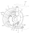
도 1은 본 발명의 일실시예에 따른 인휠 구동장치의 설치 상태의 일례를 도시한 사시도이다.
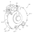
도 2는 본 발명의 일실시예에 따른 인휠 구동장치에 캘리퍼가 설치된 상태를 도시한 사시도이다.
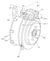
도 3은 본 발명의 일실시예에 따른 인휠 구동장치에 캘리퍼가 설치된 상태를 다른 방향에서 도시한 사시도이다.
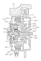
도 4는 도 3의 A-A선상에서 본 발명의 일실시예에 따른 인휠 구동장치를 도시한 단면도이다.
도 5는 도 3의 B-B선상에서 본 발명의 일실시예에 따른 인휠 구동장치를 도시한 단면도이다.
도 6은 본 발명의 일실시예에 따른 인휠 구동장치를 도시한 사시도이다.
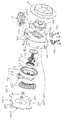
도 7은 본 발명의 일실시예에 따른 인휠 구동장치를 도시한 분해 사시도이다.
도 8은 본 발명의 일실시예에 따른 인휠 구동장치의 허브베어링을 도시한 사시도이다.
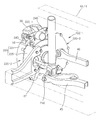
도 9는 본 발명의 다른 일실시예에 따른 인휠 구동장치의 설치 상태의 일례를 도시한 사시도이다.
도 10은 본 발명의 다른 일실시예에 따른 인휠 구동장치의 설치 상태의 일례를 다른 방향에서 도시한 사시도이다.
도 11은 본 발명의 또 다른 일실시예에 따른 인휠 구동장치의 설치 상태의 일례를 도시한 사시도이다.1 is a perspective view showing an example of the installation state of the in-wheel drive apparatus according to an embodiment of the present invention.
Figure 2 is a perspective view showing a state in which a caliper is installed in the in-wheel drive apparatus according to an embodiment of the present invention.
Figure 3 is a perspective view showing a state in which the caliper is installed in the in-wheel drive apparatus according to an embodiment of the present invention from another direction.
4 is a cross-sectional view illustrating an in-wheel driving apparatus according to an embodiment of the present invention on the line AA of FIG. 3.
5 is a cross-sectional view illustrating an in-wheel driving apparatus according to an exemplary embodiment of the present invention on the line BB of FIG. 3.
Figure 6 is a perspective view of the in-wheel drive apparatus according to an embodiment of the present invention.
Figure 7 is an exploded perspective view showing an in-wheel drive device according to an embodiment of the present invention.
8 is a perspective view showing a hub bearing of the in-wheel drive device according to an embodiment of the present invention.
9 is a perspective view showing an example of an installation state of the in-wheel drive apparatus according to another embodiment of the present invention.
10 is a perspective view showing an example of the installation state of the in-wheel drive apparatus according to another embodiment of the present invention from another direction.
11 is a perspective view showing an example of an installation state of the in-wheel drive apparatus according to another embodiment of the present invention.
이하, 첨부된 도면들을 참조하여 본 발명에 따른 인휠 모터 및 인휠 구동장치의 일실시예를 설명한다.Hereinafter, an embodiment of an in-wheel motor and an in-wheel driving apparatus according to the present invention will be described with reference to the accompanying drawings.
이 과정에서 도면에 도시된 선들의 두께나 구성요소의 사이즈 등은 설명의 명료성과 편의상 과장되게 도시되어 있을 수 있다.In this process, the thicknesses of the lines and the size of the elements shown in the drawings may be exaggerated for clarity and convenience of description.
또한, 후술되는 용어들은 본 발명에서의 기능을 고려하여 정의된 용어들로서 이는 사용자, 운용자의 의도 또는 관례에 따라 달라질 수 있다. 그러므로, 이러한 용어들에 대한 정의는 본 명세서 전반에 걸친 내용을 토대로 내려져야 할 것이다.
In addition, terms to be described below are terms defined in consideration of functions in the present invention, which may vary according to the intention or convention of a user or an operator. Therefore, definitions of these terms should be made based on the contents throughout the specification.
도 1은 본 발명의 일실시예에 따른 인휠 구동장치의 설치 상태의 일례를 도시한 사시도이고, 도 2, 3은 본 발명의 일실시예에 따른 인휠 구동장치에 캘리퍼가 설치된 상태를 다양한 방향에서 도시한 사시도이다.1 is a perspective view showing an example of the installation state of the in-wheel drive apparatus according to an embodiment of the present invention, Figures 2 and 3 are a state in which the caliper is installed in the in-wheel drive apparatus according to an embodiment of the present invention in various directions It is a perspective view shown.
도 4는 도 3의 A-A선상에서 본 발명의 일실시예에 따른 인휠 구동장치를 도시한 단면도이고, 도 5는 도 3의 B-B선상에서 본 발명의 일실시예에 따른 인휠 구동장치를 도시한 단면도이다.4 is a cross-sectional view showing an in-wheel drive device according to an embodiment of the present invention on the line AA of Figure 3, Figure 5 is a cross-sectional view showing an in-wheel drive device according to an embodiment of the present invention on the line BB of Figure 3 to be.
도 6은 본 발명의 일실시예에 따른 인휠 구동장치를 도시한 사시도이고, 도 7은 본 발명의 일실시예에 따른 인휠 구동장치를 도시한 분해 사시도이며, 도 8은 본 발명의 일실시예에 따른 인휠 구동장치의 허브베어링을 도시한 사시도이다.6 is a perspective view showing an in-wheel drive device according to an embodiment of the present invention, Figure 7 is an exploded perspective view showing an in-wheel drive device according to an embodiment of the present invention, Figure 8 is an embodiment of the present invention It is a perspective view showing the hub bearing of the in-wheel drive according to the.
도 9, 10은 본 발명의 다른 일실시예에 따른 인휠 구동장치의 설치 상태의 일례를 다양한 방향에서 도시한 사시도이고, 도 11은 본 발명의 또 다른 일실시예에 따른 인휠 구동장치의 설치 상태의 일례를 도시한 사시도이다.9 and 10 are perspective views showing an example of the installation state of the in-wheel drive device according to another embodiment of the present invention in various directions, Figure 11 is an installation state of the in-wheel drive device according to another embodiment of the present invention It is a perspective view which shows an example of this.
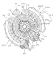
도 1 내지 도 5를 참조하면, 본 발명의 일실시예에 따른 인휠 구동장치(200)는 모터회전자(211), 모터고정자(215), 모터커버(220), 캘리퍼연결구(240), 현가장치연결구(250), 조향장치연결구(260), 감속기(270), 허브베어링(280)을 포함한다.1 to 5, the in-
모터회전자(211)는 모터고정자(215)가 형성하는 자계의 영향을 받아 정위치(正位置) 회전한다.The
도 4, 5를 참조하면, 모터회전자(211)는 회전자축(212)과, 자성회전체(214)를 포함한다.4 and 5, the
회전자축(212)은 베어링(230)에 의해 회전가능하게 축지지된다.The
자성회전체(214)는 영구자석 또는 금속과 같은 자성체를 포함하여 회전자축의 둘레에 결합되며, 모터고정자(215)에 의해 형성되는 자계의 영향을 받아, 회전자축(212)과 함께 회전하게 된다.The magnetic
회전자축(212)의 회전중심부에는 샤프트(213)가 형성되며, 샤프트(213)에는 샤프트(213)의 회전 변위를 감속시켜 토크를 증가시키 위한 감속기(170)가 연결된다.A
모터고정자(215)는 모터회전자(211)의 둘레에 복수개가 이격되게 설치되며, 모터회전자(211)를 회전시키는 자계를 형성한다.The
도 1에 도시된 바와 같이 본 발명의 일실시예에 따른 인휠 구동장치(200)를 휠(10) 내측에 설치한 상태에서, 모터회전자(211)는 휠(10)의 회전 중심과 동축상에 위치되며, 모터고정자(215)는 모터회전자(211)와 휠(10) 사이에 위치된다.As shown in FIG. 1, in a state in which the in-
도 5를 참조하면, 모터고정자(215) 중 모터회전자(211)와 근접하게 위치되는 일측부(이하 '내면부'라 한다)는 모터회전자(211)의 둘레에 대응되는 호(Arc) 형상의 곡면을 이룬다.Referring to FIG. 5, one side of the
본 발명의 일실시예에 따른 인휠 구동장치(200)의 모터고정자(215)는 모터회전자(211)의 둘레 중 90°변위에 대응되는 호 형상의 내면부를 가지는 2개가 등간격을 두고 대칭되게 설치된 구조를 가진다.The
모터고정자(215)를 모터회전자(211)의 둘레에 등간격을 두고 배치하면, 모터고정자(215)에 의해 형성되는 자계가 모터회전자(211)의 360° 전(全) 둘레에 걸쳐 등간격을 두고 균일하게 작용하게 된다.When the
이에 따라, 모터회전자(211)에 작용하는 자계가 일측으로 편중되지 않아, 모터회전자(211)의 회전이 안정되게 이루어질 수 있다.Accordingly, since the magnetic field acting on the
복수개의 모터고정자(215)가 서로 동일한 형상을 가지는 경우, 모터고정자(215)를 등간격을 두고 배치하면, 복수개의 모터고정자(215)는 모터회전자(211)의 회전 중심을 기준으로 자연히 대칭을 이루게 된다.When the plurality of
모터고정자(215)가 서로 다른 형상을 가지는 경우, 모터고정자(215)를 모터회전자(211)의 둘레에 대칭을 이루어 배치하면, 대칭의 기준이 되는 지점을 기준으로 하여 모터회전자(211)에 작용시키는 자계를 편중되게 조정할 수도 있다. When the
모터회전자(211)와 모터고정자(215)를 각각 영구자석과 전자석을 포함하도록 구성하면, 브러시리스 모터(BLDC Motor, Brushless DC Motor) 또는 영구자석 동기 모터(PMSM, Permanent Magnet Synchronous Motor) 구조를 구현할 수 있다.When the
모터회전자(211)와 모터고정자(215)를 각각 금속과 같은 자성체, 전자석을 포함하도록 구성하면, 유도전동기 또는 스위치드 릴럭턴스 모터(SRM, Switched Reluctance Motor) 구조를 구현할 수 있다.When the
모터고정자(215)에 자계를 형성하고, 모터회전자(211)를 회전 구동시키는 작용, 원리와 이를 구현하기 위한 구체적인 구성 부품에 대해서는 모터 분야의 공지기술을 따르는 바 그 상세한 설명을 생략한다.Forming a magnetic field on the
모터커버(220)는 모터회전자(211)와 모터고정자(215)를 커버링하며, 모터회전자(211)와 복수개의 모터고정자(215)를 함께 수용가능한 연통된 수용공간을 제공한다.The
도 2, 4, 5를 참조하면, 본 발명의 일실시예에 따른 모터커버(220)는, 모터수용부(221)와 덮개부(225)를 포함한다.2, 4, and 5, the
모터수용부(221)는 모터회전자(211)와 모터고정자(215)를 내부에 수용가능한 오목한 형상을 가진다.The
모터수용부(221)에는 모터수용부(221) 내부에 수용된 모터회전자(211)의 회전자축(212)의 샤프트부(213)가 관통되는 홀부(223)가 형성된다.The
덮개부(225)는 모터수용부(221)의 개방부(222)(도 4 참조)를 차폐하며 모터수용부(221)에 결합된다.The
모터수용부(221)에 형성된 홀부(223)와, 덮개부(225) 중 회전자축(212)의 회전 중심에 대응되는 위치에 오목하게 형성된 홈부상에는 회전자축(212)을 회전가능하게 지지하는 복수개의 베어링(230)이 설치된다.The
모터회전자(211)는, 상기와 같이 베어링(230)을 매개로 하여, 모터커버(220)의 내면부와 간극을 두고 간섭 없이 모터커버(220) 내측에 안정되게 설치된 상태를 유지할 수 있다.As described above, the
모터커버(220)는 모터회전자(211)의 둘레에 배치되는 모터고정자(215)의 외면부와, 모터고정자(215)에 의해 커버링되지 않는 모터회전자(211)의 외면부 일부를 함께 커버링한다.The
이하 설명에서는 모터커버(220) 중 모터회전자(211)의 외면부를 커버링하는 부분과, 모터고정자(215)의 외면부를 커버링하는 부분을 각각 회전자커버부(220-1)와 고정자커버부(220-2)로 지칭한다.In the following description, portions of the
5를 참조하면, 본 발명의 일실시예에서 회전자커버부(220-1)와 고정자커버부(220-2)는 모터회전자(211), 모터고정자(215)의 외면부를 따라 연속하여 연장되면서 상호 일체로 연결된 구조를 가진다.Referring to 5, in one embodiment of the present invention, the rotor cover part 220-1 and the stator cover part 220-2 extend continuously along the outer surface of the
본 발명의 일실시예에 따른 회전자커버부(220-1)는, 그 내면부가 모터회전자(211)의 외면부로부터 일정한 간극을 가진다.In the rotor cover portion 220-1 according to the embodiment of the present invention, the inner surface portion thereof has a predetermined gap from the outer surface portion of the
본 발명의 일실시예에 따른 고정자커버부(220-2)는, 회전자커버부(220-1)와 마찬가지로 그 내면부가 모터고정자(215)의 외면부로부터 일정한 간극을 가진다.Stator cover portion 220-2 according to an embodiment of the present invention, like the rotor cover portion 220-1, its inner surface portion has a predetermined gap from the outer surface portion of the
여기서, 일정한 간극을 가진다는 것은, 하나의 수치(예를 들어, 2mm 등) 뿐만 아니라 설정 간극 범위(예를 들어, 2mm~2cm) 이내의 간극을 가진다는 것을 의미한다.Here, to have a constant gap means that not only one numerical value (for example, 2 mm, etc.) but also a gap within a set gap range (for example, 2 mm to 2 cm).
회전자커버부(220-1)와 고정자커버부(220-2)는 도 5에 도시된 바와 같이 모터회전자(211), 모터고정자(215) 각각의 외면부와 서로 다른 간극을 가질 수도 있다. As shown in FIG. 5, the rotor cover 220-1 and the stator cover 220-2 may have different gaps from the outer surfaces of the
본 발명의 일실시예에서 회전자커버부(220-1)와 고정자커버부(220-2)는 모터회전자(211), 모터고정자(215) 각각의 외면부와 일정한 간극을 가지나, 본 발명에 따른 모터커버(220)는 이에 한정되는 것은 아니다.In an embodiment of the present invention, the rotor cover 220-1 and the stator cover 220-2 have a predetermined gap with the outer surface of the
본 발명에 따른 모터커버(220)는 회전자커버부(220-1)와 고정자커버부(220-2) 중 일측만이 모터회전자(211)와 모터고정자(215)의 외면부로부터 일정한 간극을 가지는 등 다양한 변형 실시가 가능하다.In the
캘리퍼연결구(240)는, 원형의 모터회전자(211) 둘레에 복수개가 상호 이격되게 배치된 모터고정자(215) 사이에서, 모터커버(220)의 회전자커버부(220-1)상에 형성된다.The
도 2를 참조하면, 본 발명의 일실시예에 따른 캘리퍼연결구(240)는 체결부재를 이용하여 캘리퍼(30)를 결합가능하게 체결부재가 관통가능한 체결홀부를 구비하여 모터커버(220)의 회전자커버부(220-1)에 형성된다.2, the
현가장치연결구(250)는 캘리퍼연결구(240)와 마찬가지로 모터고정자(215) 사이에 형성된 이격공간상에서 모터커버(220)의 회전자커버수(220-1)상에 고정설치된다.The
도 6을 참조하면, 본 발명의 일실시예에 따른 현가장치연결구(250)는 회동 운동하는 현가장치(40)의 단부와 용이하게 결합시킬 수 있는 볼 조인트(Ball Joint) 구조를 가진다. Referring to Figure 6, the
조향장치연결구(260) 또한 현가장치연결구(250)와 마찬가지로 모터고정자(215) 사이에 형성된 이격공간상에서 모터커버(220)의 회전자커버수(220-1)상에 고정설치된다.The
도 6을 참조하면, 본 발명의 일실시예에 따른 조향장치연결구(260)는 회동 운동하는 조향장치(60)의 단부와 용이하게 결합시킬 수 있는 볼 조인트 구조를 가진다.Referring to Figure 6, the
캘리퍼(30)를 포함하는 제동장치, 현가장치(40)의 단부, 조향장치(60)의 단부는 도 1에 도시된 바와 같이 캘리퍼연결구(240), 현가장치연결구(250), 조향장치연결구(260)에 각각 조립, 결합된다.The braking device including the
복수개의 모터고정자(215)를 이격간격을 두고 모터회전자(211) 둘레에 배치하면, 회전자커버부(220-1)와 휠(10) 사이에는 모터고정자(215)간 이격간격에 대응되는 만큼의 이격공간이 형성된다.When the plurality of
본 발명의 일실시예에서, 캘리퍼연결구(240)는 모터고정자(215) 사이에 형성되는 복수개의 이격공간 중 일측에서 회전자커버부(220-1)상에 형성된다.In one embodiment of the present invention, the
캘리퍼(30)는 회전자커버부(220-1)와 휠(10) 사이에 형성된 여유 공간상에서 캘리퍼연결구(240)에 연결, 설치된다.The
현가장치연결구(250)와 조향장치연결구(260)는, 모터고정자(215) 사이에 형성되는 복수개의 이격공간 중 다른 일측에서 회전자커버부(220-1)상에 형성된다.The
현가장치(40)와 조향장치(60)의 단부는 회전자커버부(220-1)와 휠(10) 사이에 형성된 다른 여유 공간상에서 현가장치연결구(250)와 조향장치연결구(260)에 각각 연결, 설치된다.The ends of the suspension device 40 and the
도 1은 현가장치(40)로써 맥퍼슨 스트럿 서스펜션(MacPherson Strut Suspension)(41)을 전륜에 적용한 일예를 도시한 것이다.1 illustrates an example in which a MacPherson Strut Suspension 41 is applied to a front wheel as a suspension device 40.
맥퍼슨 스트럿 서스펜션(41)은 전륜에 주로 적용되는데, 전륜의 경우 제동장치, 현가장치(40) 이외에 조향장치(60)가 추가로 휠(10)측에 결합되어야 한다.The McPherson strut suspension 41 is mainly applied to the front wheels. In the case of the front wheels, in addition to the brake system and the suspension system 40, the
맥퍼슨 스트럿 서스펜션(41)의 로워암(Lower Arm)(42)을 현가장치연결구(250)에 연결하고, 현가장치연결구(250)와 동일한 여유공간상에 위치하는 조향장치연결구(260)에 조향장치(60)를 연결시킴으로써 맥퍼슨 스트럿 서스펜션 구조를 적용할 수 있다.The
맥퍼슨 스트럿 서스펜션(41)을 구성하는 부품 중, 스트럿(Strut)(43)과 같이 회동 구동되지 않고 휠(10)측에 고정설치되는 나머지 부품은, 모터커버(220)상의 적정 위치에 고정설치할 수 있다.Among the parts constituting the McPherson strut suspension 41, the remaining parts which are fixed to the
감속기(270)는 모터회전자(211)의 회전 변위를 감속하여 출력한다.The
도 4, 5, 7을 참조하면, 본 발명의 일실시예에 따른 감속기(270)는 선기어(271), 링기어(272), 유성기어(273), 캐리어(274)를 포함한다.4, 5, and 7, the
선기어(271)는 회전자축(212)의 샤프트부(213)에 연결되어 모터회전자(211)와 동축 회전되며, 외주부에 기어치가 형성된다.The
링기어(272)는 내주부에 기어치를 구비하여 선기어(271) 외측에 이격되게 설치된다. The
유성기어(273)는 선기어(271)와 링기어(272) 사이에 설치되며, 선기어(271)의 회전에 연동하여 자전 및 공전한다.The
캐리어(274)는 유성기어(273) 각각의 회전 중심에 연결되어 유성기어(273)의 공전에 대응되는 속도로 감속되어 회전되고, 회전 중심부에 출력축(276)이 형성된다.The
감속기(270)는 선기어(271), 링기어(272), 유성기어(273)가 동심원을 이루며 배치된 유성기어열(Planetary Gear Trains)의 구조에 의해 감속을 구현하게 된다.The
링기어(272)를 고정시키고, 선기어(271)를 회전 구동시키면, 복수개의 유성기어(273)에 연결된 캐리어(274)는 선기어(271)와 동일한 방향으로 감속 회전된다.When the
도 4, 7, 8을 참조하면, 허브베어링(280)은 감속기(270)의 출력축(276)을 회전가능하게 축지지하며, 모터커버(220)에 고정설치된다.4, 7 and 8, the hub bearing 280 rotatably supports the
모터커버(220)는 휠(10)에, 허브베어링(280)은 모터커버(220)에 고정설치되며, 허브베어링(280)에는 브레이크 디스크(50)가 결합되고, 캘리퍼(30)는 브레이크 디스크(50)측으로의 변위를 가지도록 캘리퍼연결구(240)상에 설치된다.The
이에 따라, 제동장치 작동 시, 캘리퍼(30)는 브레이크 패드를 브레이크 디스크(50)측으로 밀어내면서 휠(10)을 제동시키게 된다.Accordingly, when the braking device is operated, the
감속기(270)의 일측부에 위치되는 선기어(271)는 회전자축(212)을 지지하는 베어링(230)에 의해 회전가능하게 지지되며, 감속기(270)의 타측부에 위치되는 캐리어(274)는 허브베어링(280)에 의해 회전가능하게 지지된다.The
감속기(270)는 상기와 같이 베어링(230)과 허브베어링(280)을 포함한 복수개의 베어링부재에 의해 안정되게 축지지된 상태를 유지하며 정위치 회전될 수 있다.The
도 9, 10은 현가장치(40)로써 멀티링크 서스펜션(Multi-Link Suspension)(44)을 후륜에 적용한 일례를 도시한 것이다.9 and 10 show an example in which a multi-link suspension 44 is applied to the rear wheel as the suspension device 40.
맥퍼슨 스트럿 서스펜션(41)을 적용하는 경우와 비교해, 조향장치(60)를 결합하는 조향장치연결구(260)가 형성되지 않는 차이점을 가진다.Compared to the case where the McPherson strut suspension 41 is applied, the
회전자커버부(220-1)와 휠(10) 사이에 형성되는 복수개의 여유 공간 중 캘리퍼(30)가 설치되지 않은 다른 여유 공간상에서 멀티링크 서스펜션(44)의 로워암(45)을 현가장치연결구(250)에 연결함으로써, 멀티링크 서스펜션 구조를 적용할 수 있다.Suspension of the
멀티링크 서스펜션(44)을 구성하는 부품 중, 어퍼암(Upper Arm)(46), 어시스트암(Assist Arm)(47)과 같은 다른 부품은, 모터커버(220)상의 적정 위치에 고정설치할 수 있다.Among the components constituting the multi-link suspension 44, other components such as the
도 11은 현가장치(40)로써 커플드 토션빔 액슬 서스펜션(CTBA Suspension, Coupled Torsion Beam Axle Suspension)(48)을 후륜에 적용한 일례를 도시한 것이다.11 illustrates an example in which a coupled torsion beam axle suspension (CTBA Suspension) 48 is applied to the rear wheel as the suspension device 40.
스핀들 마운팅 브라켓(Spindle Mounting Bracket)(49)을 캘리퍼(30)와 간섭되지 않게 모터커버(220)의 일면에 고정설치함으로써, 커플드 토션빔 액슬 서스펜션(48)을 간단하게 적용할 수 있다.By fixing the
상기와 같은 구성을 가지는 본 발명의 실시예에 따른 인휠 구동장치(200)는, 모터회전자(211) 둘레에 복수개의 모터고정자(215)를 상호 이격되게 배치함으로써, 모터회전자(211)와 휠(10) 사이에 차량의 다른 부품을 설치할 수 있는 여유공간부를 형성할 수 있다.In-
본 발명은 제동장치, 현가장치(40), 조향장치(60)와 같이 차량의 휠(10)과 연결되는 차량 부품을 모터회전자(211)와 휠(10) 사이에 형성되는 복수개의 여유공간부상에 자유롭게 배치할 수 있다.The present invention provides a plurality of free spaces formed between the
즉, 본 발명은 모터회전자(211)와 모터고정자(215)를 포함하는 인휠 모터(210)의 사이즈를 축소시키거나, 휠(10)의 사이즈를 확장시킬 필요가 없이, 휠(10) 내부의 한정된 공간상에 모터회전자(211), 모터고정자(215), 제동장치, 현가장치(40), 조향장치(60) 등을 공간효율적으로 탑재할 수 있다.That is, the present invention does not need to reduce the size of the in-
또한, 본 발명은 모터회전자(211)와 휠(10) 사이에 형성되는 복수개의 여유공간부를 활용하여, 전륜에 적용되는 맥퍼슨 스트럿 서스펜션, 후륜에 적용되는 멀티링크 서스펜션, 커플드 토션빔 액슬 서스펜션 등의 다양한 사양을 적용할 수 있다.In addition, the present invention utilizes a plurality of free spaces formed between the
본 발명은 휠(10)에 대응되는 사이즈를 가지는 인휠 모터(210)를 적용할 수 있으며, 인휠 모터의 사이즈를 모터회전자(211)에 대응되는 사이즈로 축소시키는 경우와 비교해, 현격한 토크를 증가를 구현할 수 있다.
The present invention can be applied to the in-
본 발명은 도면에 도시된 실시예를 참고로 하여 설명되었으나, 이는 예시적인 것에 불과하며, 당해 기술이 속하는 분야에서 통상의 지식을 가진 자라면 이로부터 다양한 변형 및 균등한 타 실시예가 가능하다는 점을 이해할 것이다. 따라서 본 발명의 기술적 보호범위는 아래의 특허청구범위에 의해서 정하여져야 할 것이다.
While the present invention has been particularly shown and described with reference to exemplary embodiments thereof, it will be understood by those of ordinary skill in the art that various changes in form and details may be made therein without departing from the spirit and scope of the invention as defined by the appended claims. I will understand. Accordingly, the technical scope of the present invention should be defined by the following claims.
10 : 휠 30 : 캘리퍼
40 : 현가장치 41 : 맥퍼슨 스트럿 서스펜션
42, 45 :로워암 43 : 스트럿
44 : 멀티링크 서스펜션 46 : 어퍼암
47 : 어시스트암 48 : 커플드 토션빔 액슬 서스펜션
49 : 스핀들 마운팅 브라켓 200 : 인휠 구동장치
210 : 인휠 모터 211 : 모터회전자
212 : 회전자축 213 : 샤프트부
214 : 자성회전체 215 : 모터고정자
220 : 모터커버 221 : 모터수용부
222 : 개방부 223 : 홀부
225 : 덮개부 230 : 베어링
240 : 캘리퍼연결구 250 : 현가장치연결구
260 : 조향장치연결구 270 : 감속기
271 : 선기어 272 : 링기어
273 : 유성기어 274 : 캐리어
276 : 출력축 280 : 허브베어링10: wheel 30: caliper
40: suspension 41: McPherson strut suspension
42, 45: Lower arm 43: Strut
44: multi-link suspension 46: upper arm
47: assist arm 48: coupled torsion beam axle suspension
49: spindle mounting bracket 200: in-wheel drive
210: in wheel motor 211: motor rotor
212: rotor shaft 213: shaft portion
214: magnetic rotating body 215: motor stator
220: motor cover 221: motor receiving portion
222: opening portion 223: hole portion
225: cover 230: bearing
240: caliper connector 250: suspension device connector
260: steering gear connector 270: reducer
271: sun gear 272: ring gear
273
276: output shaft 280: hub bearing
Claims (25)
상기 모터회전자의 둘레에 복수개가 이격되게 설치되며, 상기 모터회전자를 회전시키는 자계를 형성하는 모터고정자;
를 포함하는 것을 특징으로 하는 인휠 모터.
A motor rotor installed inside the wheel of the vehicle; And
A plurality of motor stators spaced apart from each other around the motor rotor and forming a magnetic field for rotating the motor rotor;
In-wheel motor comprising a.
상기 모터고정자는,
상기 모터회전자의 둘레에 등간격을 두고 배치되는 것을 특징으로 하는 인휠 모터.
The method of claim 1,
The motor stator,
In-wheel motor, characterized in that arranged at equal intervals around the motor rotor.
상기 모터고정자는,
상기 모터회전자의 둘레에 대칭을 이루어 배치되는 것을 특징으로 하는 인휠 모터.
The method of claim 1,
The motor stator,
In-wheel motor, characterized in that the symmetrical arrangement around the motor rotor.
상기 모터회전자는, 영구자석을 포함하여 구성되며,
상기 모터고정자는, 전자석을 포함하여 구성되는 것을 특징으로 하는 인휠 모터.
4. The method according to any one of claims 1 to 3,
The motor rotor is configured to include a permanent magnet,
The motor stator, the in-wheel motor, characterized in that it comprises an electromagnet.
상기 모터회전자와 상기 모터고정자는, 브러시리스 모터(BLDC Motor, Brushless DC Motor) 또는 영구자석 동기 모터(PMSM, Permanent Magnet Synchronous Motor)를 이루는 것을 특징으로 하는 인휠 모터.
5. The method of claim 4,
The motor rotor and the motor stator, the brushless motor (BLDC Motor, Brushless DC Motor) or permanent magnet synchronous motor (PMSM), characterized in that the in-wheel motor.
상기 모터회전자는, 금속과 같은 자성체를 포함하여 구성되며,
상기 모터고정자는, 전자석을 포함하여 구성되는 것을 특징으로 하는 인휠 모터.
4. The method according to any one of claims 1 to 3,
The motor rotor is composed of a magnetic material such as metal,
The motor stator, the in-wheel motor, characterized in that it comprises an electromagnet.
상기 모터회전자와 상기 모터고정자는, 유도전동기 또는 스위치드 릴럭턴스 모터(SRM, Switched Reluctance Motor)를 이루는 것을 특징으로 하는 인휠 모터.
The method according to claim 6,
The motor rotor and the motor stator, the in-wheel motor, characterized in that to form a switched reluctance motor (SRM).
상기 모터회전자의 둘레에 복수개가 이격되게 설치되며, 상기 모터회전자를 회전시키는 자계를 형성하는 모터고정자;
상기 모터회전자와 상기 모터고정자를 커버링하는 모터커버; 및
상기 모터고정자 사이에 형성된 이격공간상에서 상기 모터커버에 연결되며, 캘리퍼가 고정설치되는 캘리퍼연결구;
를 포함하는 것을 특징으로 하는 인휠 구동장치.
A motor rotor installed inside the wheel of the vehicle;
A plurality of motor stators spaced apart from each other around the motor rotor and forming a magnetic field for rotating the motor rotor;
A motor cover covering the motor rotor and the motor stator; And
A caliper connector connected to the motor cover in a space formed between the motor stators, the caliper being fixedly installed;
In-wheel drive device comprising a.
상기 모터회전자는,
베어링에 의해 회전가능하게 축지지되는 회전자축; 및
영구자석 또는 금속과 같은 자성체를 포함하여 상기 회전자축의 둘레에 결합되며, 상기 모터고정자에 의해 형성되는 자계의 영향으로 회전되는 자성회전체;
를 포함하는 것을 특징으로 하는 인휠 구동장치.
9. The method of claim 8,
The motor rotor,
A rotor shaft rotatably supported by a bearing; And
A magnetic rotating body coupled to the circumference of the rotor shaft including a magnetic material such as a permanent magnet or a metal, and rotated under the influence of a magnetic field formed by the motor stator;
In-wheel drive device comprising a.
상기 모터고정자는,
상기 모터회전자의 둘레에 등간격을 두고 배치되는 것을 특징으로 하는 인휠 구동장치.
9. The method of claim 8,
The motor stator,
In-wheel drive device characterized in that arranged at equal intervals around the motor rotor.
상기 모터고정자는,
상기 모터회전자의 둘레에 대칭을 이루어 배치되는 것을 특징으로 하는 인휠 구동장치.
9. The method of claim 8,
The motor stator,
In-wheel drive device characterized in that the symmetrical arrangement around the motor rotor.
상기 모터커버는,
상기 모터회전자의 외면부를 커버링하는 회전자커버부; 및
상기 모터고정자의 외면부를 커버링하는 고정자커버부;
를 포함하는 것을 특징으로 하는 인휠 구동장치.
9. The method of claim 8,
The motor cover,
A rotor cover part covering an outer surface of the motor rotor; And
A stator cover portion covering an outer surface portion of the motor stator;
In-wheel drive device comprising a.
상기 회전자커버부는,
내면부가 상기 모터회전자의 외면부로부터 일정한 간극을 가지는 것을 특징으로 하는 인휠 구동장치.
The method of claim 12,
The rotor cover portion,
In-wheel drive device, characterized in that the inner surface portion has a predetermined gap from the outer surface portion of the motor rotor.
상기 고정자커버부는,
내면부가 상기 모터고정자의 외면부로부터 일정한 간극을 가지는 것을 특징으로 하는 인휠 구동장치.
The method of claim 12,
The stator cover portion,
In-wheel drive apparatus, characterized in that the inner surface portion has a predetermined gap from the outer surface portion of the motor stator.
상기 캘리퍼연결구는,
상기 회전자커버부에 형성되는 것을 특징으로 하는 인휠 구동장치.
The method of claim 12,
The caliper connector,
In-wheel drive device, characterized in that formed on the rotor cover.
상기 모터커버는,
상기 모터회전자와 상기 모터고정자를 내부에 수용가능한 오목한 형상을 가지며, 상기 회전자축의 샤프트부가 관통되는 모터수용부; 및
상기 모터수용부의 개방부를 차폐하며 상기 모터수용부에 결합되는 덮개부;
를 포함하는 것을 특징으로 하는 인휠 구동장치.
9. The method of claim 8,
The motor cover,
A motor accommodating part having a concave shape accommodating the motor rotor and the motor stator therein and passing through a shaft part of the rotor shaft; And
A cover part which shields the opening of the motor accommodating part and is coupled to the motor accommodating part;
In-wheel drive device comprising a.
상기 모터고정자 사이에 형성된 이격공간상에서 상기 모터커버에 고정설치되며, 현가장치의 단부가 연결되는 현가장치연결구;
를 더 포함하는 것을 특징으로 하는 인휠 구동장치.
9. The method of claim 8,
Suspension device connector is fixed to the motor cover in the separation space formed between the motor stator, the end of the suspension device is connected;
In-wheel drive device characterized in that it further comprises.
상기 캘리퍼연결구는, 상기 모터고정자 사이에 형성되는 복수개의 이격공간 중 일측에 위치되며,
상기 현가장치연결구는, 상기 모터고정자 사이에 형성되는 복수개의 이격공간 중 다른 일측에 위치되는 것을 특징으로 하는 인휠 구동장치.
18. The method of claim 17,
The caliper connector is located on one side of the plurality of spaced spaces formed between the motor stator,
The suspension connector, the in-wheel drive device, characterized in that located on the other side of the plurality of spaced spaces formed between the motor stator.
상기 현가장치연결구는, 맥퍼슨 스트럿 서스펜션(MacPherson Strut Suspension)의 로워암(Lower Arm)과 연결되며,
상기 맥퍼슨 스트럿 서스펜션의 스트럿(Strut)은, 상기 모터커버에 고정설치되는 것을 특징으로 하는 인휠 구동장치.
18. The method of claim 17,
The suspension connector is connected to the lower arm of the MacPherson Strut Suspension,
The strut of the McPherson strut suspension is fixed to the motor cover, characterized in that the in-wheel drive device.
상기 현가장치연결구는, 멀티링크 서스펜션(Multi-Link Suspension)의 로워암(Lower Arm)과 연결되며,
상기 멀티링크 서스펜션의 어퍼암(Upper Arm), 어시스트암(Assist Arm)은, 상기 모터커버에 고정설치되는 것을 특징으로 하는 인휠 구동장치.
18. The method of claim 17,
The suspension connector is connected to the lower arm of the multi-link suspension,
The upper arm and the assist arm of the multi-link suspension are fixed to the motor cover.
커플드 토션빔 액슬 서스펜션(CTBA Suspension, Coupled Torsion Beam Axle Suspension)의 스핀들 마운팅 브라켓(Spindle Mounting Bracket)이 상기 모터커버에 고정설치되는 것을 특징으로 하는 인휠 구동장치.
18. The method of claim 17,
In-wheel drive device, characterized in that the spindle mounting bracket (CTBA Suspension, Coupled Torsion Beam Axle Suspension) is fixed to the motor cover.
상기 모터고정자 사이에 형성된 이격공간상에서 상기 모터커버에 고정설치되며, 조향장치의 단부가 연결되는 조향장치연결구;
를 더 포함하는 것을 특징으로 하는 인휠 구동장치.
The method according to claim 8 or 17,
A steering device connector that is fixed to the motor cover in a space formed between the motor stators, and to which an end of the steering device is connected;
In-wheel drive device characterized in that it further comprises.
상기 캘리퍼연결구는, 상기 모터고정자 사이에 형성되는 복수개의 이격공간 중 일측에 위치되며,
상기 조향장치연결구는, 상기 모터고정자 사이에 형성되는 복수개의 이격공간 중 다른 일측에 위치되는 것을 특징으로 하는 인휠 구동장치.
The method of claim 22,
The caliper connector is located on one side of the plurality of spaced spaces formed between the motor stator,
The steering apparatus connector, the in-wheel drive apparatus, characterized in that located on the other side of the plurality of spaced spaces formed between the motor stator.
상기 모터회전자의 회전 변위를 감속하여 출력하는 감속기; 및
상기 감속기의 출력축을 회전가능하게 축지지하며, 상기 모터커버에 고정설치되는 허브베어링;
을 포함하는 것을 특징으로 하는 인휠 구동장치.
9. The method of claim 8,
A reducer configured to reduce and output a rotational displacement of the motor rotor; And
A hub bearing rotatably supporting the output shaft of the reducer and fixed to the motor cover;
In-wheel drive device comprising a.
상기 감속기는,
상기 모터회전자에 연결되어 상기 모터회전자와 동축 회전되며, 외접 기어치가 형성된 선기어;
내접 기어치를 구비하여 상기 선기어 외측에 이격되게 설치되는 링기어;
상기 선기어와 상기 링기어 사이에 설치되며, 상기 선기어의 회전에 연동하여 자전 및 공전하는 유성기어; 및
상기 유성기어 각각의 회전 중심에 연결되어 상기 유성기어의 공전에 대응되는 속도로 감속되어 회전되고, 회전 중심부에 상기 출력축이 형성되는 캐리어;
를 포함하는 것을 특징으로 하는 인휠 구동장치.25. The method of claim 24,
The speed reducer includes:
A sun gear connected to the motor rotor and coaxially rotating with the motor rotor and having external gear teeth;
A ring gear provided with an internal gear tooth and spaced apart from the outside of the sun gear;
A planetary gear disposed between the sun gear and the ring gear and rotating and revolving in conjunction with rotation of the sun gear; And
A carrier which is connected to the rotation center of each of the planetary gears and is decelerated and rotated at a speed corresponding to the revolution of the planetary gears, and the output shaft is formed at the center of rotation;
In-wheel drive device comprising a.
Priority Applications (3)
| Application Number | Priority Date | Filing Date | Title |
|---|---|---|---|
| KR1020120076181A KR101552982B1 (en) | 2012-07-12 | 2012-07-12 | In-wheel motor and in-wheel working device |
| CN201210523589.4A CN103545976B (en) | 2012-07-12 | 2012-12-07 | Wheel hub motor and hub drive device |
| US13/727,367 US9331546B2 (en) | 2012-07-12 | 2012-12-26 | In-wheel motor and in-wheel driving device |
Applications Claiming Priority (1)
| Application Number | Priority Date | Filing Date | Title |
|---|---|---|---|
| KR1020120076181A KR101552982B1 (en) | 2012-07-12 | 2012-07-12 | In-wheel motor and in-wheel working device |
Publications (2)
| Publication Number | Publication Date |
|---|---|
| KR20140015704A true KR20140015704A (en) | 2014-02-07 |
| KR101552982B1 KR101552982B1 (en) | 2015-09-14 |
Family
ID=49913410
Family Applications (1)
| Application Number | Title | Priority Date | Filing Date |
|---|---|---|---|
| KR1020120076181A KR101552982B1 (en) | 2012-07-12 | 2012-07-12 | In-wheel motor and in-wheel working device |
Country Status (3)
| Country | Link |
|---|---|
| US (1) | US9331546B2 (en) |
| KR (1) | KR101552982B1 (en) |
| CN (1) | CN103545976B (en) |
Cited By (1)
| Publication number | Priority date | Publication date | Assignee | Title |
|---|---|---|---|---|
| KR20180119006A (en) * | 2017-04-24 | 2018-11-01 | 경성대학교 산학협력단 | Resonant magnetic induction charging system using wheel-type SRM for electric vehicle drive |
Families Citing this family (41)
| Publication number | Priority date | Publication date | Assignee | Title |
|---|---|---|---|---|
| US9561715B2 (en) * | 2012-11-16 | 2017-02-07 | Deere & Company | Wheel hub with electric motor |
| NO335839B1 (en) | 2012-12-10 | 2015-03-02 | Jakob Hatteland Logistics As | Robot for transporting storage containers |
| US10414271B2 (en) | 2013-03-01 | 2019-09-17 | Delbert Tesar | Multi-speed hub drive wheels |
| US9862263B2 (en) | 2013-03-01 | 2018-01-09 | Delbert Tesar | Multi-speed hub drive wheels |
| US10626964B2 (en) | 2013-03-12 | 2020-04-21 | Motus Labs, LLC | Axial cam gearbox mechanism |
| US10428916B2 (en) | 2013-03-12 | 2019-10-01 | Motus Labs, LLC | Spiral cam gearbox mechanism |
| US10151375B2 (en) | 2013-03-12 | 2018-12-11 | Motus Labs, LLC | Motorized gearbox mechanism |
| US11015685B2 (en) | 2013-03-12 | 2021-05-25 | Motus Labs, LLC | Axial cam gearbox mechanism |
| US9261176B2 (en) | 2013-03-12 | 2016-02-16 | Carlos A. Hoefken | Gearbox mechanism |
| US10240666B2 (en) | 2013-03-12 | 2019-03-26 | Motus Labs, LLC | Simplified gearbox mechanism |
| KR101462790B1 (en) * | 2013-06-21 | 2014-11-20 | 현대위아 주식회사 | Lear suspension mounting structure for an electronic vehicle |
| CN104052224B (en) * | 2014-06-12 | 2017-01-25 | 成都奇门科技有限公司 | electromagnetic force hub motor |
| NO337544B1 (en) | 2014-06-19 | 2016-05-02 | Jakob Hatteland Logistics As | Remote controlled vehicle assembly to pick up storage containers from a storage system |
| CN105437950B (en) * | 2014-09-30 | 2019-02-15 | 上海中科深江电动车辆有限公司 | Wheel drive system |
| CN104401397A (en) * | 2014-11-22 | 2015-03-11 | 湖北荆硕自动化设备有限公司 | Omnidirectional traveling driving device |
| CN105691102A (en) * | 2014-11-24 | 2016-06-22 | 舍弗勒技术有限两合公司 | Hub driving assembly |
| TWI538363B (en) * | 2014-12-02 | 2016-06-11 | 財團法人工業技術研究院 | Compliance motor structure and manufacturing method thereof |
| ES2751745T3 (en) | 2015-01-28 | 2020-04-01 | Autostore Tech As | Robot to transport storage containers |
| TWM506736U (en) * | 2015-03-10 | 2015-08-11 | 吳震洋 | Extended-range charging driving device for electric vehicle |
| JP6670571B2 (en) * | 2015-09-28 | 2020-03-25 | Ntn株式会社 | Connection structure between in-wheel motor drive device and strut type suspension device |
| US9598141B1 (en) * | 2016-03-07 | 2017-03-21 | Future Motion, Inc. | Thermally enhanced hub motor |
| US10112680B2 (en) | 2016-03-07 | 2018-10-30 | Future Motion, Inc. | Thermally enhanced hub motor |
| EP3261237A1 (en) * | 2016-06-21 | 2017-12-27 | Jan-Dirk Reimers | Wheel hub drive with segmented sectional electric machine operating according to the reluctance principle |
| CN106026504A (en) * | 2016-07-27 | 2016-10-12 | 深圳先进技术研究院 | Mecanum electric wheel and omnibearing mobile platform |
| CN106696593A (en) * | 2017-01-06 | 2017-05-24 | 苏州凤凰动力工业有限公司 | Mecanum wheel with speed reducing mechanism |
| DE102017106810A1 (en) * | 2017-03-29 | 2018-10-04 | Emm! Solutions Gmbh | Arm |
| JP2018192887A (en) * | 2017-05-16 | 2018-12-06 | トヨタ自動車株式会社 | Suspension device for non-steering drive wheel with built-in in-wheel motor |
| US10940751B2 (en) * | 2017-08-09 | 2021-03-09 | Nsk Ltd. | Electric vehicle driving device |
| JP2019043412A (en) * | 2017-09-04 | 2019-03-22 | トヨタ自動車株式会社 | Connecting structure of in-wheel motor unit and strut-type suspension device |
| EP3477820B1 (en) * | 2017-10-26 | 2021-02-24 | Jan-Dirk Reimers | Electrical ring machine for inverter operation |
| US10513186B1 (en) * | 2017-11-01 | 2019-12-24 | Denis Vasilyevich Shchurovskiy | In-wheel electric motor with an increased electromagnetic flux and energy recovery brake |
| CN108023435A (en) * | 2018-01-31 | 2018-05-11 | 江苏工大金凯高端装备制造有限公司 | A kind of attachment device between electric mover and component |
| KR102016254B1 (en) * | 2018-03-09 | 2019-08-29 | 엘지전자 주식회사 | Inwheel motor driving device |
| KR102186716B1 (en) * | 2018-04-19 | 2020-12-04 | 홍성도 | Electric motor Anti-lock brake system control device |
| WO2019231469A1 (en) * | 2018-06-01 | 2019-12-05 | Motus Labs, LLC | Motorized gearbox mechanism |
| CN108749557B (en) * | 2018-07-03 | 2021-09-21 | 王玉琨 | Electric vehicle wheel assembly |
| JP2020069963A (en) * | 2018-11-01 | 2020-05-07 | Ntn株式会社 | In-wheel motor drive device and coupling structure for brake caliper |
| JP7103173B2 (en) * | 2018-11-05 | 2022-07-20 | トヨタ自動車株式会社 | Suspension device, vehicle |
| AT522589B1 (en) | 2019-06-08 | 2020-12-15 | Omnidirectional wheel hub drive | |
| BR102019019631A2 (en) * | 2019-09-20 | 2021-03-30 | Manoel Neto | INTEGRATED ROAD SYSTEM |
| US11827092B2 (en) * | 2020-03-02 | 2023-11-28 | Komatsu America Corp. | Vehicle with front-wheel-assist system |
Family Cites Families (22)
| Publication number | Priority date | Publication date | Assignee | Title |
|---|---|---|---|---|
| US5442250A (en) * | 1990-10-09 | 1995-08-15 | Stridsberg Licencing Ab | Electric power train for vehicles |
| DE4125044A1 (en) * | 1991-07-29 | 1993-02-04 | Wolfgang Hill | ELECTRIC MOTOR DESIGNED AS A DISC RUNNER WITH RADIAL AND RADIAL PACKAGE ARRANGED TO THE ROTATIONAL AXIS |
| US5465802A (en) * | 1994-06-16 | 1995-11-14 | Yang; Chen-Chi | Electromotive wheel with a disengageable stator |
| DE60217661T2 (en) * | 2001-04-16 | 2007-11-15 | Kabushiki Kaisha Bridgestone | MOUNTING PROCEDURE FOR WHEEL-BUILT ENGINE AND WHEEL-BUILT ENGINE SYSTEM |
| US7128327B2 (en) * | 2001-06-21 | 2006-10-31 | Bridgestone Corporation | Axle with rubber cushion |
| US20040212259A1 (en) * | 2003-04-24 | 2004-10-28 | Gould Len Charles | Wheel motor |
| JP4225134B2 (en) * | 2003-06-25 | 2009-02-18 | トヨタ自動車株式会社 | Vehicle suspension system |
| US20080078631A1 (en) * | 2004-02-05 | 2008-04-03 | Erlston Lester J | Disc brake in combination with brushless electric motor-generator |
| JP2005231564A (en) * | 2004-02-23 | 2005-09-02 | Ntn Corp | Electric wheel driving device |
| JP4347121B2 (en) * | 2004-04-15 | 2009-10-21 | 横浜ゴム株式会社 | Transponder used for in-wheel motor system and wheel equipped with the transponder |
| JP4391884B2 (en) | 2004-05-26 | 2009-12-24 | 本田技研工業株式会社 | Wheel drive device for vehicle |
| JP4879191B2 (en) * | 2005-01-13 | 2012-02-22 | ザ ティムケン カンパニー | High reduction ratio electric hub drive |
| JP4450208B2 (en) * | 2005-01-19 | 2010-04-14 | 三菱自動車工業株式会社 | In-wheel motor |
| JP4682045B2 (en) | 2006-01-17 | 2011-05-11 | 株式会社ミツバ | In-wheel motor for electric vehicles |
| JP5133572B2 (en) * | 2006-02-02 | 2013-01-30 | 株式会社ブリヂストン | Mounting method and mounting structure of dynamic vibration absorber and in-wheel motor |
| JP3960553B1 (en) * | 2006-03-31 | 2007-08-15 | 本田技研工業株式会社 | Wheel rotation device for in-wheel motor vehicle |
| JP2008010033A (en) * | 2006-06-27 | 2008-01-17 | Toshiba Corp | Disk device |
| JP4724075B2 (en) * | 2006-08-29 | 2011-07-13 | 本田技研工業株式会社 | Wheel rotation device |
| CN101197516B (en) * | 2007-12-10 | 2012-02-22 | 蔡国法 | Wheel hub electric motor of electric vehicle |
| EP2365916B1 (en) * | 2008-11-14 | 2013-06-12 | Actua S.r.l. | Electric motor wheel assembly |
| KR20110040459A (en) | 2009-10-14 | 2011-04-20 | 삼성테크윈 주식회사 | Apparatus of driving wheels for in-wheel system |
| JP5307165B2 (en) * | 2011-01-14 | 2013-10-02 | 株式会社小松製作所 | In-wheel motor |
-
2012
- 2012-07-12 KR KR1020120076181A patent/KR101552982B1/en active IP Right Grant
- 2012-12-07 CN CN201210523589.4A patent/CN103545976B/en active Active
- 2012-12-26 US US13/727,367 patent/US9331546B2/en active Active
Cited By (1)
| Publication number | Priority date | Publication date | Assignee | Title |
|---|---|---|---|---|
| KR20180119006A (en) * | 2017-04-24 | 2018-11-01 | 경성대학교 산학협력단 | Resonant magnetic induction charging system using wheel-type SRM for electric vehicle drive |
Also Published As
| Publication number | Publication date |
|---|---|
| US20140015382A1 (en) | 2014-01-16 |
| CN103545976B (en) | 2017-03-01 |
| KR101552982B1 (en) | 2015-09-14 |
| CN103545976A (en) | 2014-01-29 |
| US9331546B2 (en) | 2016-05-03 |
Similar Documents
| Publication | Publication Date | Title |
|---|---|---|
| KR101552982B1 (en) | In-wheel motor and in-wheel working device | |
| KR101278914B1 (en) | Mounting structure of in wheel motor system | |
| JP5565388B2 (en) | In-wheel motor drive device | |
| KR101441813B1 (en) | Device for driving rear wheel of electric vehicle | |
| CN1739994B (en) | Housing structure of in-wheel motor | |
| JP5677142B2 (en) | In-wheel type wheel drive device | |
| US9254741B2 (en) | In-wheel actuator and in-wheel assembly comprising the same | |
| KR20200143831A (en) | In-wheel working device | |
| US20180118022A1 (en) | In-wheel working device | |
| WO2007139299A1 (en) | Coreless motor having rotors arranged concentrically and driving apparatus having the motor | |
| KR20140081351A (en) | In-wheel motor assembly | |
| US20210075289A1 (en) | Motor, vehicle power unit with motor, generator, vehicle wheel bearing with generator | |
| KR20140023793A (en) | In-wheel actuator and in-wheel assembly comprising the same | |
| KR20140014847A (en) | In-wheel driving device easy to repair motor | |
| JP2000052788A (en) | Motor-drive vehicle | |
| CN110212697A (en) | A kind of wheeled robot wheel hub driving integrated motor | |
| KR20100085647A (en) | In-wheel motor for electric vehicle | |
| JP2012214203A (en) | In-wheel motor driving device | |
| KR101871161B1 (en) | In-wheel working device | |
| US20210197655A1 (en) | Vehicle drive device with reduction device | |
| US11691503B2 (en) | Vehicle drive device with variable transmission | |
| CN115296482A (en) | Hub motor with axial magnetic flux built-in planetary reducer | |
| JP2019205241A (en) | Three-phase permanent magnet synchronous motor, vehicle power device including the same, and generator and generator-equipped wheel bearing including the same | |
| JP3224745U (en) | Wheel power generation system | |
| WO2016024319A1 (en) | Vehicle braking system, rotating electrical machine, and vehicle |
Legal Events
| Date | Code | Title | Description |
|---|---|---|---|
| A201 | Request for examination | ||
| E902 | Notification of reason for refusal | ||
| E902 | Notification of reason for refusal | ||
| E701 | Decision to grant or registration of patent right | ||
| GRNT | Written decision to grant | ||
| FPAY | Annual fee payment |
Payment date: 20180820 Year of fee payment: 4 |