KR20140008692A - Apparatus for supporting shaft coupling member - Google Patents
Apparatus for supporting shaft coupling member Download PDFInfo
- Publication number
- KR20140008692A KR20140008692A KR1020120075553A KR20120075553A KR20140008692A KR 20140008692 A KR20140008692 A KR 20140008692A KR 1020120075553 A KR1020120075553 A KR 1020120075553A KR 20120075553 A KR20120075553 A KR 20120075553A KR 20140008692 A KR20140008692 A KR 20140008692A
- Authority
- KR
- South Korea
- Prior art keywords
- shaft joint
- shaft
- joint member
- holding means
- shaft coupling
- Prior art date
- Legal status (The legal status is an assumption and is not a legal conclusion. Google has not performed a legal analysis and makes no representation as to the accuracy of the status listed.)
- Ceased
Links
Images


Classifications
-
- B—PERFORMING OPERATIONS; TRANSPORTING
- B66—HOISTING; LIFTING; HAULING
- B66F—HOISTING, LIFTING, HAULING OR PUSHING, NOT OTHERWISE PROVIDED FOR, e.g. DEVICES WHICH APPLY A LIFTING OR PUSHING FORCE DIRECTLY TO THE SURFACE OF A LOAD
- B66F3/00—Devices, e.g. jacks, adapted for uninterrupted lifting of loads
- B66F3/24—Devices, e.g. jacks, adapted for uninterrupted lifting of loads fluid-pressure operated
- B66F3/25—Constructional features
- B66F3/30—Constructional features with positive brakes or locks
-
- B—PERFORMING OPERATIONS; TRANSPORTING
- B66—HOISTING; LIFTING; HAULING
- B66F—HOISTING, LIFTING, HAULING OR PUSHING, NOT OTHERWISE PROVIDED FOR, e.g. DEVICES WHICH APPLY A LIFTING OR PUSHING FORCE DIRECTLY TO THE SURFACE OF A LOAD
- B66F3/00—Devices, e.g. jacks, adapted for uninterrupted lifting of loads
- B66F3/24—Devices, e.g. jacks, adapted for uninterrupted lifting of loads fluid-pressure operated
- B66F3/25—Constructional features
- B66F3/36—Load-engaging elements
-
- B—PERFORMING OPERATIONS; TRANSPORTING
- B66—HOISTING; LIFTING; HAULING
- B66F—HOISTING, LIFTING, HAULING OR PUSHING, NOT OTHERWISE PROVIDED FOR, e.g. DEVICES WHICH APPLY A LIFTING OR PUSHING FORCE DIRECTLY TO THE SURFACE OF A LOAD
- B66F2700/00—Lifting apparatus
- B66F2700/09—Other lifting devices
Landscapes
- Life Sciences & Earth Sciences (AREA)
- Engineering & Computer Science (AREA)
- Geology (AREA)
- Mechanical Engineering (AREA)
- Structural Engineering (AREA)
- Load-Engaging Elements For Cranes (AREA)
Abstract
본 발명에 따른 축이음부재 지지장치는, 양측 회전부재를 연결하는 축이음부재 하부에 배치된 장치본체; 및 상기 장치본체에 승강되도록 제공되어, 상기 축이음부재로터 상기 회전부재의 분리 시 하강되는 상기 축이음부재를 상방 지지하는 홀드수단;을 포함한다.
이와 같이 본 발명은, 상기 축이음부재로터 회전부재의 분리 시 하강되는 축이음부재를 상방 지지하는 홀드수단과, 아울러 분리된 회전부재의 탈거경로에 축이음부재가 비간섭 되도록 축이음부재를 이동시키기 위해 홀드수단을 이동시키는 이동수단이 구성됨으로써, 중량물인 축이음부재의 지지 및 이동작업을 안전하게 수행함으로써 안전사고의 위험성을 제거할 수 있고, 축이음부재에 교체된 회전부재의 결합시 축이음부재의 회전이 가능하여 정밀한 결합작업을 수행할 수 있으며, 나아가 중량물 취급공정에서의 작업시간을 현저하게 감소시킬 수 있다.An apparatus for supporting a shaft joint member according to the present invention includes: an apparatus body disposed below the shaft joint member connecting both rotating members; And a holding means provided to be elevated on the apparatus main body to support the shaft coupling member upwardly descending when the rotation member is separated from the shaft coupling member.
In this way, the present invention, the holding means for supporting the shaft joint member that is lowered when the rotary member rotor member is separated, and the shaft joint member is moved so that the shaft joint member is not interfered with the separation path of the separated rotary member. The movement means for moving the holding means is configured to securely carry out the support and movement of the shaft joint member which is heavy, thereby eliminating the risk of a safety accident, and the shaft joint when the rotating member is replaced with the shaft joint member. It is possible to rotate the member to perform a precise joining operation, further reducing the working time in the heavy material handling process.

Description
본 발명은 축이음부재 지지장치로서, 중량물인 축이음부재로부터 회전부재를 분리하고 다시 결합시 축이음부재를 안정적으로 지지하고 이동시키는 축이음부재 지지장치에 관한 것이다.
The present invention relates to a shaft joint member support device, which is a shaft joint member support device for stably supporting and moving the shaft joint member when separating and rotating the rotary member from the shaft joint member which is a heavy object.
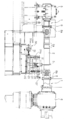
도 1은 종래기술에 따른 축이음부재인 유니버셜조인트가 크레인줄에 의해 상방 지지되는 것을 나타낸 도이다.1 is a view showing that the universal joint, which is a shaft joint member according to the prior art, is supported upward by a crane string.
도면을 참조하면, 주조롤(7)과 모터(4)와의 동력전달을 위한 축이음부재(2)에는, 일례로서 두 축의 중심이 일치하지 않아도 동력을 원활히 전달할 수 있는 유니버셜조인트가 사용될 수 있다.Referring to the drawings, a
일례로서, 상기 축이음부재(2)는 도시된 바와 같이, 일측으로는 모터(4)에 체결된 감속기(5)의 단부인 회전부재(1)와, 타측으로는 주조롤(7)의 일측에 장착된 주조롤 로터리조인트(6)의 단부인 회전부재(1)와 축이음될 수 있다.As an example, the
이러한 축이음부재(2)는 큰 동력을 전달해야 하므로 그에 맞게 부피와 중량도 따라서 커지게 된다.
Since the
일반적으로, 축이음부재(2)를 롤 또는 모터(4)와 분리하거나 조립할 때에는, 고중량의 축이음부재(2)를 크레인줄(9)에 매단 다음, 체결을 위해 사용된 볼트를 분리하거나 분리된 양측 부재를 볼트로 조립한 후 다시 적정 위치에 안치시킨다.Generally, when separating or assembling the
이때, 작업자는 중량물을 취급하므로 작업시간이 과다하게 소모되는 단점이 있다.In this case, since the worker handles the heavy object, there is a disadvantage in that the working time is excessively consumed.
아울러, 포스트립 공장의 주조 롤 축이음부재(2)는 약 500Kg의 중량인데, 일주일에 3~4번씩 발생되는 잦은 롤 교환 작업 시 중량물 취급으로 작업자는 언제나 안전사고의 위험성이 높다.In addition, the cast roll shaft joint member (2) of the post-lip plant is about 500Kg in weight, the operator always has a high risk of safety accidents by handling heavy materials during frequent roll change operations occurring three to four times a week.
또한, 포스트립 공장의 축이음부재(2)는 취부 시 플랜지(8)의 체결볼트(8a)를 체결하고자 양측 플랜지(8)들의 체결홀에 서로 일치시키기 위해, 회전을 요하는 정밀한 작업성을 요한다. 그러나 회전이 어려운 크레인줄(9)로는 이러한 정밀한 작업이 불가능하다.
In addition, the
본 발명은 상기와 같은 문제점을 해결하기 위해 창안된 것으로서, 중량물인 축이음부재로부터 회전부재를 분리하고 다시 결합시 축이음부재를 안정적으로 지지하고 이동시키는 축이음부재 지지장치를 제공하는 데에 그 목적이 있다.
The present invention has been made to solve the above problems, to provide a shaft joint member support device for stably supporting and moving the shaft joint member when the rotating member is separated from the shaft joint member that is a heavy object and recombined. There is a purpose.
상기와 같은 목적을 달성하기 위하여 본 발명의 바람직한 실시예에 따른 축이음부재 지지장치는, 양측 회전부재를 연결하는 축이음부재 하부에 배치된 장치본체; 및 상기 장치본체에 승강되도록 제공되어, 상기 축이음부재로터 상기 회전부재의 분리 시 하강되는 상기 축이음부재를 상방 지지하는 홀드수단;을 포함한다.
In order to achieve the above object, a shaft joint member supporting apparatus according to a preferred embodiment of the present invention includes: an apparatus body disposed below the shaft joint member connecting both rotating members; And a holding means provided to be elevated on the apparatus main body to support the shaft coupling member upwardly descending when the rotation member is separated from the shaft coupling member.
그리고, 본 발명은 상기 장치본체에 제공되되, 분리된 상기 회전부재의 탈거경로에 상기 축이음부재가 비간섭 되도록, 상기 홀드수단을 이동시키는 이동수단;을 더 포함할 수 있다.
The present invention may further include a moving means provided in the apparatus main body and moving the holding means such that the shaft joint member is intrusive to the detachment path of the separated rotating member.
여기에서, 상기 홀드수단은, 상기 장치몸체에 제공되는 홀드프레임; 상기 홀드프레임으로부터 상승하여 상기 축이음부재 하부를 지지하는 리프팅부재; 및 상기 리프팅부재와 연결되어, 상기 리프팅부재를 승강시키도록 구동력을 제공하는 승강구동부재;를 구비하는 것이 바람직하다.
Here, the holding means, the holding frame provided on the device body; A lifting member which lifts from the hold frame and supports the shaft coupling member lower portion; And an elevating driving member connected to the lifting member and providing a driving force to elevate the lifting member.
이때, 상기 축이음부재에는 돌출턱이 형성되고, 상기 리프팅부재의 상부에는 상기 돌출턱이 끼움되는 체결홈을 가진 체결부가 형성된 것이 바람직하다.
At this time, the shaft fitting member is formed with a protruding jaw, the upper portion of the lifting member is preferably formed with a fastening portion having a fastening groove in which the protruding jaw is fitted.
이에 더하여, 상기 홀드수단은 상기 리프팅부재와 연결되어 상하운동되는 연결판; 및 상기 연결판으로부터 하방연장된 가이드바;를 더 구비하며, 상기 홀드프레임에는 상기 가이드바가 삽입되어 상하슬라이드 되는 가이드홈이 형성될 수 있다.In addition, the holding means is connected to the lifting member connected to the vertical plate; And a guide bar extended downward from the connecting plate, and the guide frame may be formed with a guide groove into which the guide bar is inserted to slide up and down.
아울러, 상기 홀드수단은, 상기 리프팅부재와 연결판에 의해 연결되어 상기 축이음부재 하부를 지지하되, 회전가능한 지지롤러;를 더 구비하는 것이 바람직하다.
In addition, the holding means is connected to the lifting member and the connecting plate to support the lower portion of the shaft coupling member, it is preferable to further include a rotatable support roller.
한편, 상기 축이음부재에는 스플라인축이음이 형성되어 길이방향 신축되고, 상기 이동수단은, 상기 홀드수단과 연결되어 상기 홀드수단을 상기 축이음부재의 길이방향으로 이동시키도록 구동력을 제공하는 이동구동부재;를 구비하는 것이 바람직하다.
Meanwhile, a spline shaft joint is formed in the shaft joint member so as to extend in the longitudinal direction, and the moving unit is connected to the holding unit to provide a driving force to move the holding unit in the longitudinal direction of the shaft joint member. It is preferable to have a member.
본 발명에 따른 축이음부재 지지장치는, 축이음부재로터 회전부재의 분리 시 하강되는 축이음부재를 상방 지지하는 홀드수단과, 분리된 회전부재의 탈거경로에 축이음부재가 비간섭 되도록 축이음부재를 이동시키기 위해 홀드수단을 이동시키는 이동수단이 구성됨으로써, 중량물인 축이음부재의 지지 및 이동작업을 안전하게 수행함으로써 안전사고의 위험성을 제거할 수 있고, 축이음부재에 교체된 회전부재의 결합시 축이음부재의 회전이 가능하여 정밀한 결합작업을 수행할 수 있으며, 나아가 중량물 취급공정에서의 작업시간을 현저하게 감소시킬 수 있는 효과를 가진다.
The shaft joint member support device according to the present invention comprises a holding means for upwardly supporting the shaft joint member which is lowered when the shaft joint member rotor member is separated, and the shaft joint member so that the shaft joint member is not interfered with the separation path of the separated rotary member. By moving the holding means for moving the member to move the member is configured to safely carry out the support and movement of the shaft joint member that is heavy to eliminate the risk of safety accidents, the coupling of the rotating member replaced to the shaft joint member It is possible to rotate the joint joint member to perform a precise coupling operation, and further has the effect of significantly reducing the working time in the heavy material handling process.
도 1은 종래기술에 따른 축이음부재인 유니버셜조인트가 크레인줄에 의해 상방 지지되는 것을 나타낸 도이다.
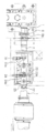
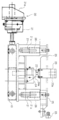
도 2는 본 발명의 바람직한 실시예에 따른 축이음부재 지지장치가 축이음부재인 유니버셜조인트의 하측에 배치된 것을 나타낸 정면도이다.
도 3은 도 2의 축이음부재 지지장치를 나타낸 평면도이다.
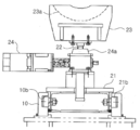
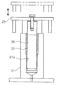
도 4는 도 3의 축이음부재 지지장치에서 상부에 체결부가 장착되고 승강구동부재에 의해 구동되는 리프팅부재를 나타낸 우측면도이다.
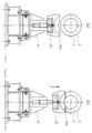
도 5는 도 4의 체결부가 상측으로 이동되어 체결홈에 축이음부재의 돌출턱이 끼움되는 것을 나타낸 도이다.
도 6은 도 2의 축이음부재 지지장치를 나타낸 확대도이다.
도 7은 도 6의 축이음부재 지지장치에서 연결판에 하방 장착된 가이드바의 상하운동을 나타낸 도이다.
도 8은 도 6의 축이음부재 지지장치에서 지지롤러가 상측으로 이동 시 축이음부재를 회전가능하게 지지하는 것을 나타낸 도이다.1 is a view showing that the universal joint, which is a shaft joint member according to the prior art, is supported upward by a crane string.
Figure 2 is a front view showing that the shaft joint member support device according to a preferred embodiment of the present invention is disposed below the universal joint that is the shaft joint member.
3 is a plan view illustrating the shaft joint member supporting apparatus of FIG. 2.
Figure 4 is a right side view showing a lifting member mounted on the upper portion in the shaft joint member support device of Figure 3 is driven by the elevating drive member.
5 is a view showing that the fastening part of the shaft fitting member is fitted into the fastening groove by moving the fastening part of FIG.
6 is an enlarged view illustrating the shaft joint member supporting apparatus of FIG. 2.
7 is a view showing the vertical movement of the guide bar mounted downward on the connecting plate in the shaft support member support device of FIG.
8 is a view showing that the support roller rotatably supports the shaft joint member when the support roller moves upward in the shaft joint member support apparatus of FIG. 6.
본 발명의 축이음부재 지지장치는, 상기 축이음부재로터 회전부재의 분리 시 하강되는 축이음부재를 상방 지지하는 홀드수단과, 분리된 회전부재의 탈거경로에 축이음부재가 비간섭 되도록 축이음부재를 이동시키기 위해 홀드수단을 이동시키는 이동수단이 구성되는 것을 기술적 특징으로 한다.
The shaft joint member support device of the present invention includes a holding means for upwardly supporting the shaft joint member which is lowered when the shaft joint member rotor rotating member is separated, and a shaft joint such that the shaft joint member does not interfere with the separation path of the separated rotary member. The technical feature is that the moving means for moving the holding means is configured to move the member.
이하, 도면을 참고하여 본 발명을 상세하게 설명하기로 한다.Hereinafter, the present invention will be described in detail with reference to the drawings.
도 2는 본 발명의 바람직한 실시예에 따른 축이음부재 지지장치가 축이음부재인 유니버셜조인트의 하측에 배치된 것을 나타낸 정면도이고, 도 3은 도 2의 축이음부재 지지장치를 나타낸 평면도이다.Figure 2 is a front view showing that the shaft joint member support device according to a preferred embodiment of the present invention is disposed below the universal joint that is the shaft joint member, Figure 3 is a plan view showing the shaft joint member support device of FIG.
도면을 참조하면, 본 발명은 바닥에 위치고정된 장치본체(10)와, 상기 장치본체(10)에 제공되는 홀드수단을 포함한다.Referring to the drawings, the present invention includes a
상기 장치본체(10)는 양측 회전부재(1)를 연결하는 축이음부재(2) 하부에 배치된다.The
이때, 일례로서 일측의 회전부재(1)는 모터(4)에 체결된 감속기(5)의 회전축이며, 타측의 회전부재(1)는 주조롤(7)(미도시)에 연결된 주조롤 로터리조인트(6)의 회전축일 수 있다.At this time, as an example, one rotating
이러한 회전부재(1)들을 이어주는 축이음부재(2)는 일례로서 두 축의 중심이 일치하지 않아도 동력을 원활히 전달할 수 있는 유니버셜조인트가 활용될 수 있다.
The
또한, 상기 홀드수단은 본체에 승강되도록 제공되어, 축이음부재(2)를 상방 지지하는 역할을 수행한다.In addition, the holding means is provided to be elevated on the main body, and serves to support the
이와 같은 홀드수단은 축이음부재(2)로부터 한 쪽의 회전부재(1)를 분리 시, 축이음부재(2)에서 분리되는 회전부재(1) 측이 하강하게 된다.The holding means is such that when one side of the
이때, 홀드수단은 축이음부재(2) 측으로 상승하여, 하강하려는 축이음부재(2)를 상방 지지할 수 있다.
At this time, the holding means may rise to the
그러면, 구체적으로 상기 홀드수단에 대해, 도 4 내지 도 8을 참조하여 살펴보기로 한다.Next, the holding means will be described in detail with reference to FIGS. 4 to 8.
도 4는 도 3의 축이음부재 지지장치에서 상부에 체결부가 장착되고 승강구동부재에 의해 구동되는 리프팅부재를 나타낸 우측면도이고, 도 5는 도 4의 체결부가 상측으로 이동되어 체결홈에 축이음부재의 돌출턱이 끼움되는 것을 나타낸 도이다.4 is a right side view showing a lifting member mounted on the upper portion of the shaft joint member supporting device of FIG. 3 and driven by a lifting driving member, and FIG. 5 is a shaft joint in the fastening groove as the fastening portion of FIG. 4 is moved upward. It is a figure which shows that the protruding jaw of a member is fitted.
또한, 도 6은 도 2의 축이음부재 지지장치를 나타낸 확대도이며, 도 7은 도 6의 축이음부재 지지장치에서 연결판에 하방 장착된 가이드바의 상하운동을 나타낸 도이고, 도 8은 도 6의 축이음부재 지지장치에서 지지롤러가 상측으로 이동 시 축이음부재를 회전가능하게 지지하는 것을 나타낸 도이다.In addition, Figure 6 is an enlarged view showing the shaft joint member support device of Figure 2, Figure 7 is a view showing the vertical movement of the guide bar mounted downward on the connecting plate in the shaft joint member support device of Figure 6, Figure 8 6 is a view showing that the support roller is rotatably supported when the support roller is moved upward in the shaft joint member support apparatus of FIG.
도면을 참조하면, 상기 홀드수단은 장치몸체에 제공되는 홀드프레임(21), 상기 홀드프레임(21)에 승강가능하도록 설치된 리프팅부재(22), 및 상기 리프팅부재(22)에 승강 구동력을 제공하는 승강구동부재(24)를 구비한다.Referring to the drawings, the holding means provides a
이때, 상기 홀드프레임(21)은 장치몸체에서 이동가능하도록 체결되어 이동수단(30)에 의해 이동될 수 있는데, 상기 이동수단(30) 및 홀드프레임(21)의 이동가능한 구체적인 구조에 대해서는 후술하기로 한다.
At this time, the
그리고, 상기 리프팅부재(22)는, 도 4 및 도 5에 도시된 바와 같이, 승강구동부재(24)에 구동력을 제공받아, 홀드프레임(21)으로부터 상승하여 축이음부재(2) 하부를 지지하도록 구성될 수 있다.And, the
이때, 상기 축이음부재(2)는 돌출턱(3)이 형성될 수 있는데, 상기 돌출턱(3)은 바람직하게 축이음부재(2)의 외주면을 따라 돌출된 환형의 돌출라인으로 구성될 수 있다.At this time, the
이러한 축이음부재(2)의 돌출턱(3)과 대응되게, 상기 리프팅부재(22)의 상부에는 체결홈(23a)을 가진 체결부(23)가 형성될 수 있는데, 상기 체결홈(23a)은 돌출턱(3)이 끼움될 수 있도록 돌출턱(3)의 형상과 대응되게 형성된다.
Corresponding to the protruding
이와 같이 리프팅부재(22)는, 상승하여 축이음부재(2)가 내려오지 않도록 상방 지지할 수 있으며, 축이음부재(2)의 돌출턱(3)이 삽입되는 체결홈(23a)을 지닌 체결부(23)로 인하여 일정위치에서 축이음부재(2)를 지지할 수 있다.In this way, the
아울러, 체결부(23)의 체결홈(23a)에 돌출턱(3)이 삽입체결됨에 따라, 이동수단(30)에 의해 축이음부재(2)를 이동시킬 수 있도록, 축이음부재(2)를 지지하는 홀드수단이 이동방향에 대한 걸림수단으로 활용될 수 있다.In addition, as the
즉, 이동수단(30)에 의해 이동되는 홀드수단에서 체결부(23)가 돌출턱(3)을 미는 작용을 함에 따라, 축이음부재(2)가 연동되어 이동될 수 있다.
That is, as the fastening
한편, 상기 리프팅부재(22)에는 승강력을 제공하는 승강구동부재(24)가 연결되는데, 상기 승강구동부재(24)는 도시된 바와 같이 모터(4)가 이용될 수 있는데, 이때 상기 모터(4)는 기어박스(24a)에 의해 회전력이 상하구동력으로 방향전환될 수 있다.On the other hand, the
나아가, 상기 승강구동부재(24)는 실린더 등 본 발명에 의해 한정되지 않고 어떠한 구동부재도 활용될 수 있음은 물론이다.
Furthermore, the
상기 홀드수단은 이에 더하여, 도 6 및 도 7에 도시된 바와 같이, 리프팅부재(22)와 연결되어 상하운동되는 연결판(25)과, 상기 연결판(25)으로부터 하방연장된 가이드바(26)를 더 구비할 수 있다.6 and 7, the holding means may be connected to the
이때, 상기 홀드프레임(21)에는 상기 가이드바(26)가 삽입되어 상하슬라이드 되는 가이드홈(21a)이 형성될 수 있다. 아울러, 이러한 가이드홈(21a) 내에는 슬라이드 마찰되는 가이드바의 손상을 방지하고자 부싱(22)이 장착될 수 있다.In this case, the holding
이와 같은 가이드바(26)는 축이음부재(2)를 지지하는 리프팅부재(22)가 받는 축이음부재(2)의 전체하중을 분산시킴으로써, 축이음부재(2)에 대한 리프팅부재(22)의 상부 지지를 안전하게 할 수 있다.
The
그리고, 상기 홀드수단은 리프팅부재(22)와 연결판(25)에 의해 연결된 지지롤러(27)를 더 구비할 수 있다.In addition, the holding means may further include a
즉, 상기 지지롤러(27)는 도 6 및 도 8에 도시된 바와 같이, 연결판(25)의 상승 시 올라가서 축이음부재(2) 하부를 지지하되, 회전가능하도록 연결판(25)에 설치될 수 있다.That is, the
축이음부재(2)로부터 분리된 회전부재(1)를 다시 결합시, 즉 일례로서 축이음부재(2)인 유니버셜조인트에 교체된 주조롤 로터리조인트(6)를 체결시, 체결볼트(8a)를 끼우기 위해 서로 마주보는 플랜지(8)에서의 체결홀을 맞추도록 축이음부재(2)를 회전하는 경우, 지지롤러(27) 상에서 원활하게 회전하도록 할 수 있다.
When the
한편, 본 발명은 장치본체(10)에 제공되는 이동수단(30)을 더 포함할 수 있다.On the other hand, the present invention may further include a moving means 30 provided in the device body (10).
상기 이동수단(30)은 분리된 회전부재(1)의 탈거경로에 축이음부재(2)가 비간섭 되도록, 홀드수단을 이동시키는 역할을 수행한다.The moving means 30 serves to move the holding means so that the shaft
이러한 이동수단(30)은 홀드수단과 연결되어 상기 홀드수단을 축이음부재(2)의 길이방향으로 이동시키도록 구동력을 제공하는 이동구동부재(31)를 구비할 수 있다.The movement means 30 may be provided with a
구체적으로, 상기 이동구동부재(31)는, 도 4 및 도 6에 도시된 바와 같이, 홀드프레임(21)에 연결되는데, 이때 상기 홀드프레임(21) 하부 양측에는 걸림턱(21b)이 형성되고, 이러한 걸림턱(21b)은 장치본체(10)의 이동홈(10a)에 걸려서 이동홈(10a)을 따라 슬라이드할 수 있다.Specifically, the movable driving
즉, 이동구동부재(31)에 의해 제공되는 수평구동력에 의해 홀드프레임(21)을 축이음부재(2)의 길이방향으로 이동시킴으로써 홀드수단 전체가 이동하게 되고, 결과적으로 상기 홀드수단이 지지하는 축이음부재(2)가 길이방향에서 수축하게 된다.That is, the whole holding means moves by moving the holding
물론, 이때 상기 축이음부재(2)에는, 도 2에 도시된 바와 같이, 스플라인축이음(2a)이 형성되어 길이방향 신축될 수 있다.
Of course, in this case, as shown in Figure 2, the shaft
여기에서, 상기 이동구동부재(31)는 도시된 바와 같이 모터(4)가 이용될 수 있는데, 이때 상기 모터(4)는 기어박스(31a)에 의해 회전력이 수평구동력으로 방향전환될 수 있다.Here, the movable driving
나아가, 상기 이동구동부재(31)는 실린더 등 본 발명에 의해 한정되지 않고 어떠한 구동부재도 활용될 수 있음은 물론이다.
Further, the movable driving
상기와 같이 본 발명은, 상기 축이음부재(2)로터 회전부재(1)의 분리 시 하강되는 축이음부재(2)를 상방 지지하는 홀드수단과, 분리된 회전부재(1)의 탈거경로에 축이음부재(2)가 비간섭 되도록 축이음부재(2)를 이동시키기 위해 홀드수단을 이동시키는 이동수단(30)이 구성됨으로써, 중량물인 축이음부재(2)의 지지 및 이동작업을 안전하게 수행함으로써 안전사고의 위험성을 제거할 수 있고, 축이음부재(2)에 교체된 회전부재(1)의 결합시 축이음부재(2)의 회전이 가능하여 정밀한 결합작업을 수행할 수 있으며, 나아가 중량물 취급공정에서의 작업시간을 현저하게 감소시킬 수 있다.
As described above, the present invention, the holding means for upwardly supporting the shaft coupling member (2) which is lowered when the rotor member (2) rotor rotation member (1) is separated, and the removal path of the separated rotary member (1) By the movement means 30 which moves the holding means to move the shaft
이상과 같이, 본 발명은 비록 한정된 실시예와 도면에 의해 설명되었으나, 본 발명은 이것에 의해 한정되지 않으며 본 발명이 속하는 기술분야에서 통상의 지식을 가진 자에 의해 본 발명의 기술사상과 아래에 기재될 특허청구범위의 균등범위 내에서 다양한 수정 및 변형 가능함은 물론이다.
While the present invention has been particularly shown and described with reference to exemplary embodiments thereof, it is to be understood that the invention is not limited to the disclosed exemplary embodiments. It is to be understood that various changes and modifications may be made without departing from the scope of the appended claims.
1 : 회전부재 2 : 축이음부재
2a : 스플라인축이음 3 : 돌출턱
4 : 모터 5 : 감속기
6 : 주조롤 로터리조인트 7 : 주조롤
8 : 플랜지 8a : 체결볼트
9 : 크레인줄 10 : 장치본체
10a : 이동홈 21 : 홀드프레임
21a : 가이드홈 21b : 걸림턱
22 : 부싱 22 : 리프팅부재
23 : 체결부 23a : 체결홈
24 : 승강구동부재 24a : 기어박수
25 : 연결판 26 : 가이드바
27 : 지지롤러 30 : 이동수단
31 : 이동구동부재 31a : 기어박스1: Rotating member 2: Shaft joint member
2a: spline shaft joint 3: protrusion jaw
4: Motor 5: Reducer
6: casting roll rotary joint 7: casting roll
8:
9 crane line 10: main body
10a: moving groove 21: hold frame
21a: guide
22
23:
24: lifting
25: connecting plate 26: guide bar
27: support roller 30: moving means
31: moving
Claims (7)
상기 장치본체(10)에 승강되도록 제공되어, 상기 축이음부재(2)로터 상기 회전부재(1)의 분리 시 하강되는 상기 축이음부재(2)를 상방 지지하는 홀드수단;
을 포함하는 축이음부재 지지장치.
An apparatus body (10) disposed under the shaft coupling member (2) connecting both rotating members (1); And
A holding means which is provided to be elevated on the apparatus main body 10 and upwardly supports the shaft coupling member 2 which is lowered when the shaft coupling member 2 is separated from the rotary member 1;
Shaft joint member support device comprising a.
상기 장치본체(10)에 제공되되, 분리된 상기 회전부재(1)의 탈거경로에 상기 축이음부재(2)가 비간섭 되도록, 상기 홀드수단을 이동시키는 이동수단(30);
을 더 포함하는 것을 특징으로 하는 축이음부재 지지장치.
The method of claim 1,
A moving means (30) provided on the apparatus main body (10) for moving the holding means such that the shaft coupling member (2) does not interfere with the separating path of the rotating member (1);
Shaft joint member support device further comprising a.
상기 홀드수단은,
상기 장치몸체에 제공되는 홀드프레임(21);
상기 홀드프레임(21)으로부터 상승하여 상기 축이음부재(2) 하부를 지지하는 리프팅부재(22); 및
상기 리프팅부재(22)와 연결되어, 상기 리프팅부재(22)를 승강시키도록 구동력을 제공하는 승강구동부재(24);
를 구비하는 것을 특징으로 하는 축이음부재 지지장치.
3. The method according to claim 1 or 2,
The holding means,
A hold frame 21 provided on the device body;
A lifting member 22 which lifts from the holding frame 21 and supports the lower portion of the shaft coupling member 2; And
An elevating driving member 24 connected with the lifting member 22 to provide a driving force to elevate the lifting member 22;
Shaft joint member support device comprising a.
상기 축이음부재(2)에는 돌출턱(3)이 형성되고,
상기 리프팅부재(22)의 상부에는 상기 돌출턱(3)이 끼움되는 체결홈(23a)을 가진 체결부(23)가 형성된 것을 특징으로 하는 축이음부재 지지장치.
The method of claim 3,
Protruding jaw (3) is formed on the shaft joint member (2),
Shaft member support device, characterized in that the upper portion of the lifting member 22 has a fastening portion (23) having a fastening groove (23a) in which the protruding jaw (3) is fitted.
상기 홀드수단은,
상기 리프팅부재(22)와 연결되어 상하운동되는 연결판(25); 및
상기 연결판(25)으로부터 하방연장된 가이드바(26);를 더 구비하며,
상기 홀드프레임(21)에는 상기 가이드바(26)가 삽입되어 상하슬라이드 되는 가이드홈(21a)이 형성된 것을 특징으로 하는 축이음부재 지지장치.
The method of claim 3,
The holding means,
A connection plate 25 connected to the lifting member 22 to move up and down; And
Further provided with a guide bar 26 extending downward from the connecting plate 25,
The holding frame (21) is a shaft joint member supporting device characterized in that the guide bar (26) is inserted into the guide groove (21a) is formed to slide up and down.
상기 홀드수단은, 상기 리프팅부재(22)와 연결판(25)에 의해 연결되어 상기 축이음부재(2) 하부를 지지하되, 회전가능한 지지롤러(27);
를 더 구비하는 것을 특징으로 하는 축이음부재 지지장치.
The method of claim 3,
The holding means is connected by the lifting member 22 and the connecting plate 25 to support the lower portion of the shaft coupling member (2), rotatable support roller (27);
Shaft joint member support device further comprising.
상기 축이음부재(2)에는 스플라인축이음(2a)이 형성되어 길이방향 신축되고,
상기 이동수단(30)은, 상기 홀드수단과 연결되어 상기 홀드수단을 상기 축이음부재(2)의 길이방향으로 이동시키도록 구동력을 제공하는 이동구동부재(31);
를 구비하는 것을 특징으로 하는 축이음부재 지지장치.3. The method of claim 2,
Spline shaft joint (2a) is formed in the shaft joint member (2) is longitudinally stretched,
The moving means (30) comprises: a moving drive member (31) connected to the holding means and providing a driving force to move the holding means in the longitudinal direction of the shaft fitting member (2);
Shaft joint member support device comprising a.
Priority Applications (1)
| Application Number | Priority Date | Filing Date | Title |
|---|---|---|---|
| KR1020120075553A KR20140008692A (en) | 2012-07-11 | 2012-07-11 | Apparatus for supporting shaft coupling member |
Applications Claiming Priority (1)
| Application Number | Priority Date | Filing Date | Title |
|---|---|---|---|
| KR1020120075553A KR20140008692A (en) | 2012-07-11 | 2012-07-11 | Apparatus for supporting shaft coupling member |
Publications (1)
| Publication Number | Publication Date |
|---|---|
| KR20140008692A true KR20140008692A (en) | 2014-01-22 |
Family
ID=50142370
Family Applications (1)
| Application Number | Title | Priority Date | Filing Date |
|---|---|---|---|
| KR1020120075553A Ceased KR20140008692A (en) | 2012-07-11 | 2012-07-11 | Apparatus for supporting shaft coupling member |
Country Status (1)
| Country | Link |
|---|---|
| KR (1) | KR20140008692A (en) |
Cited By (3)
| Publication number | Priority date | Publication date | Assignee | Title |
|---|---|---|---|---|
| CN108100966A (en) * | 2017-12-01 | 2018-06-01 | 许继电气股份有限公司 | Prefabricated cabin base turning frock |
| KR102155088B1 (en) * | 2019-08-07 | 2020-09-11 | (주)티오피에스 | Index jig |
| KR20240145216A (en) * | 2023-03-27 | 2024-10-07 | 주식회사 플랜텍 | universal yoke support apparatus and alignment method of universal yoke using of it |
-
2012
- 2012-07-11 KR KR1020120075553A patent/KR20140008692A/en not_active Ceased
Cited By (4)
| Publication number | Priority date | Publication date | Assignee | Title |
|---|---|---|---|---|
| CN108100966A (en) * | 2017-12-01 | 2018-06-01 | 许继电气股份有限公司 | Prefabricated cabin base turning frock |
| CN108100966B (en) * | 2017-12-01 | 2021-08-17 | 许继电气股份有限公司 | Prefabricated cabin base flip tool |
| KR102155088B1 (en) * | 2019-08-07 | 2020-09-11 | (주)티오피에스 | Index jig |
| KR20240145216A (en) * | 2023-03-27 | 2024-10-07 | 주식회사 플랜텍 | universal yoke support apparatus and alignment method of universal yoke using of it |
Similar Documents
| Publication | Publication Date | Title |
|---|---|---|
| CN105947613A (en) | Automatic turnover machine | |
| CN204917836U (en) | Synchronous elevating gear | |
| CN104495636A (en) | Balanced hoisting device | |
| KR20130000407U (en) | Jib crane | |
| CN117657936B (en) | Traveling crane equipment | |
| CN202423956U (en) | Hoisting device for power transmission line maintenance | |
| KR200459219Y1 (en) | Disassembling equipment for motor | |
| KR20150001693U (en) | Stand for cable drum | |
| CN204434117U (en) | A kind of balance crane assembling device | |
| CN215592312U (en) | Mine wire rope changing car | |
| KR20130059690A (en) | Apparatus for changing assembly for up/down transferring robot | |
| CN118495186B (en) | Multifunctional transfer robot | |
| JP6022007B1 (en) | Brake attachment / detachment jig | |
| CN219860272U (en) | Novel nimble efficient engineering machine tool cutting machine finished product is off line hoist and mount device | |
| CN206356846U (en) | Centrifugal rotor installing/dismounting car | |
| KR200482885Y1 (en) | Vertical type motor component lifting support device for disassemble and assemble | |
| CN104401900A (en) | Cover plate hoisting device | |
| RU2333883C1 (en) | Tower crane and method of its mounting and dismantling | |
| CN224223777U (en) | Auxiliary device for quickly disassembling and assembling roller | |
| CN220703001U (en) | Belt hoist device with adjustable | |
| CN222099323U (en) | Elevator hauler base | |
| KR101933174B1 (en) | Rotary freight loading apparatus having automatic transfer device | |
| CN216105652U (en) | Device for maintaining power equipment | |
| CN220412677U (en) | Safety hanging bracket for electromechanical construction | |
| CN216360355U (en) | Building engineering construction is with promotion support of quick installation |
Legal Events
| Date | Code | Title | Description |
|---|---|---|---|
| A201 | Request for examination | ||
| PA0109 | Patent application |
St.27 status event code: A-0-1-A10-A12-nap-PA0109 |
|
| PA0201 | Request for examination |
St.27 status event code: A-1-2-D10-D11-exm-PA0201 |
|
| D13-X000 | Search requested |
St.27 status event code: A-1-2-D10-D13-srh-X000 |
|
| D14-X000 | Search report completed |
St.27 status event code: A-1-2-D10-D14-srh-X000 |
|
| E902 | Notification of reason for refusal | ||
| PE0902 | Notice of grounds for rejection |
St.27 status event code: A-1-2-D10-D21-exm-PE0902 |
|
| T11-X000 | Administrative time limit extension requested |
St.27 status event code: U-3-3-T10-T11-oth-X000 |
|
| PG1501 | Laying open of application |
St.27 status event code: A-1-1-Q10-Q12-nap-PG1501 |
|
| E13-X000 | Pre-grant limitation requested |
St.27 status event code: A-2-3-E10-E13-lim-X000 |
|
| P11-X000 | Amendment of application requested |
St.27 status event code: A-2-2-P10-P11-nap-X000 |
|
| P13-X000 | Application amended |
St.27 status event code: A-2-2-P10-P13-nap-X000 |
|
| E902 | Notification of reason for refusal | ||
| PE0902 | Notice of grounds for rejection |
St.27 status event code: A-1-2-D10-D21-exm-PE0902 |
|
| E601 | Decision to refuse application | ||
| PE0601 | Decision on rejection of patent |
St.27 status event code: N-2-6-B10-B15-exm-PE0601 |
|
| P22-X000 | Classification modified |
St.27 status event code: A-2-2-P10-P22-nap-X000 |
|
| R18-X000 | Changes to party contact information recorded |
St.27 status event code: A-3-3-R10-R18-oth-X000 |
|
| R18-X000 | Changes to party contact information recorded |
St.27 status event code: A-3-3-R10-R18-oth-X000 |
|
| R18-X000 | Changes to party contact information recorded |
St.27 status event code: A-3-3-R10-R18-oth-X000 |
|
| R18-X000 | Changes to party contact information recorded |
St.27 status event code: A-3-3-R10-R18-oth-X000 |
|
| R18-X000 | Changes to party contact information recorded |
St.27 status event code: A-3-3-R10-R18-oth-X000 |
|
| R18-X000 | Changes to party contact information recorded |
St.27 status event code: A-3-3-R10-R18-oth-X000 |
|
| R18 | Changes to party contact information recorded |
Free format text: ST27 STATUS EVENT CODE: A-3-3-R10-R18-OTH-X000 (AS PROVIDED BY THE NATIONAL OFFICE) |
|
| R18-X000 | Changes to party contact information recorded |
St.27 status event code: A-3-3-R10-R18-oth-X000 |