KR20140000670U - Delivery device - Google Patents
Delivery device Download PDFInfo
- Publication number
- KR20140000670U KR20140000670U KR2020130004587U KR20130004587U KR20140000670U KR 20140000670 U KR20140000670 U KR 20140000670U KR 2020130004587 U KR2020130004587 U KR 2020130004587U KR 20130004587 U KR20130004587 U KR 20130004587U KR 20140000670 U KR20140000670 U KR 20140000670U
- Authority
- KR
- South Korea
- Prior art keywords
- wheel
- transport
- material supply
- shaft
- wheels
- Prior art date
- Legal status (The legal status is an assumption and is not a legal conclusion. Google has not performed a legal analysis and makes no representation as to the accuracy of the status listed.)
- Ceased
Links
- 239000000463 material Substances 0.000 claims abstract description 60
- 230000003028 elevating effect Effects 0.000 claims abstract description 4
- 238000004804 winding Methods 0.000 claims description 6
- 238000000034 method Methods 0.000 claims description 4
- 238000010276 construction Methods 0.000 description 1
- 230000000694 effects Effects 0.000 description 1
- 238000005516 engineering process Methods 0.000 description 1
- 238000009434 installation Methods 0.000 description 1
- 238000004519 manufacturing process Methods 0.000 description 1
- 239000002699 waste material Substances 0.000 description 1
Images

Classifications
-
- B—PERFORMING OPERATIONS; TRANSPORTING
- B65—CONVEYING; PACKING; STORING; HANDLING THIN OR FILAMENTARY MATERIAL
- B65G—TRANSPORT OR STORAGE DEVICES, e.g. CONVEYORS FOR LOADING OR TIPPING, SHOP CONVEYOR SYSTEMS OR PNEUMATIC TUBE CONVEYORS
- B65G47/00—Article or material-handling devices associated with conveyors; Methods employing such devices
- B65G47/52—Devices for transferring articles or materials between conveyors i.e. discharging or feeding devices
- B65G47/53—Devices for transferring articles or materials between conveyors i.e. discharging or feeding devices between conveyors which cross one another
-
- B—PERFORMING OPERATIONS; TRANSPORTING
- B65—CONVEYING; PACKING; STORING; HANDLING THIN OR FILAMENTARY MATERIAL
- B65G—TRANSPORT OR STORAGE DEVICES, e.g. CONVEYORS FOR LOADING OR TIPPING, SHOP CONVEYOR SYSTEMS OR PNEUMATIC TUBE CONVEYORS
- B65G15/00—Conveyors having endless load-conveying surfaces, i.e. belts and like continuous members, to which tractive effort is transmitted by means other than endless driving elements of similar configuration
- B65G15/10—Conveyors having endless load-conveying surfaces, i.e. belts and like continuous members, to which tractive effort is transmitted by means other than endless driving elements of similar configuration comprising two or more co-operating endless surfaces with parallel longitudinal axes, or a multiplicity of parallel elements, e.g. ropes defining an endless surface
- B65G15/105—Conveyors having endless load-conveying surfaces, i.e. belts and like continuous members, to which tractive effort is transmitted by means other than endless driving elements of similar configuration comprising two or more co-operating endless surfaces with parallel longitudinal axes, or a multiplicity of parallel elements, e.g. ropes defining an endless surface the surface being formed by two or more ropes
-
- B—PERFORMING OPERATIONS; TRANSPORTING
- B65—CONVEYING; PACKING; STORING; HANDLING THIN OR FILAMENTARY MATERIAL
- B65G—TRANSPORT OR STORAGE DEVICES, e.g. CONVEYORS FOR LOADING OR TIPPING, SHOP CONVEYOR SYSTEMS OR PNEUMATIC TUBE CONVEYORS
- B65G23/00—Driving gear for endless conveyors; Belt- or chain-tensioning arrangements
- B65G23/02—Belt- or chain-engaging elements
- B65G23/04—Drums, rollers, or wheels
- B65G23/08—Drums, rollers, or wheels with self-contained driving mechanisms, e.g. motors and associated gearing
-
- B—PERFORMING OPERATIONS; TRANSPORTING
- B65—CONVEYING; PACKING; STORING; HANDLING THIN OR FILAMENTARY MATERIAL
- B65G—TRANSPORT OR STORAGE DEVICES, e.g. CONVEYORS FOR LOADING OR TIPPING, SHOP CONVEYOR SYSTEMS OR PNEUMATIC TUBE CONVEYORS
- B65G23/00—Driving gear for endless conveyors; Belt- or chain-tensioning arrangements
- B65G23/22—Arrangements or mountings of driving motors
-
- B—PERFORMING OPERATIONS; TRANSPORTING
- B65—CONVEYING; PACKING; STORING; HANDLING THIN OR FILAMENTARY MATERIAL
- B65G—TRANSPORT OR STORAGE DEVICES, e.g. CONVEYORS FOR LOADING OR TIPPING, SHOP CONVEYOR SYSTEMS OR PNEUMATIC TUBE CONVEYORS
- B65G43/00—Control devices, e.g. for safety, warning or fault-correcting
- B65G43/08—Control devices operated by article or material being fed, conveyed or discharged
-
- B—PERFORMING OPERATIONS; TRANSPORTING
- B65—CONVEYING; PACKING; STORING; HANDLING THIN OR FILAMENTARY MATERIAL
- B65G—TRANSPORT OR STORAGE DEVICES, e.g. CONVEYORS FOR LOADING OR TIPPING, SHOP CONVEYOR SYSTEMS OR PNEUMATIC TUBE CONVEYORS
- B65G47/00—Article or material-handling devices associated with conveyors; Methods employing such devices
- B65G47/74—Feeding, transfer, or discharging devices of particular kinds or types
- B65G47/88—Separating or stopping elements, e.g. fingers
-
- B—PERFORMING OPERATIONS; TRANSPORTING
- B65—CONVEYING; PACKING; STORING; HANDLING THIN OR FILAMENTARY MATERIAL
- B65G—TRANSPORT OR STORAGE DEVICES, e.g. CONVEYORS FOR LOADING OR TIPPING, SHOP CONVEYOR SYSTEMS OR PNEUMATIC TUBE CONVEYORS
- B65G2201/00—Indexing codes relating to handling devices, e.g. conveyors, characterised by the type of product or load being conveyed or handled
- B65G2201/02—Articles
- B65G2201/0214—Articles of special size, shape or weigh
- B65G2201/022—Flat
-
- B—PERFORMING OPERATIONS; TRANSPORTING
- B65—CONVEYING; PACKING; STORING; HANDLING THIN OR FILAMENTARY MATERIAL
- B65G—TRANSPORT OR STORAGE DEVICES, e.g. CONVEYORS FOR LOADING OR TIPPING, SHOP CONVEYOR SYSTEMS OR PNEUMATIC TUBE CONVEYORS
- B65G2812/00—Indexing codes relating to the kind or type of conveyors
- B65G2812/01—Conveyors composed of several types of conveyors
- B65G2812/012—Conveyors composed of several types of conveyors for conveying material successively by a series of conveyors
- B65G2812/013—Conveyors composed of several types of conveyors for conveying material successively by a series of conveyors without relative movement between conveyors
-
- B—PERFORMING OPERATIONS; TRANSPORTING
- B65—CONVEYING; PACKING; STORING; HANDLING THIN OR FILAMENTARY MATERIAL
- B65G—TRANSPORT OR STORAGE DEVICES, e.g. CONVEYORS FOR LOADING OR TIPPING, SHOP CONVEYOR SYSTEMS OR PNEUMATIC TUBE CONVEYORS
- B65G2812/00—Indexing codes relating to the kind or type of conveyors
- B65G2812/02—Belt or chain conveyors
- B65G2812/02128—Belt conveyors
- B65G2812/02138—Common features for belt conveyors
- B65G2812/02148—Driving means for the belts
Landscapes
- Engineering & Computer Science (AREA)
- Mechanical Engineering (AREA)
- Intermediate Stations On Conveyors (AREA)
- Reciprocating Conveyors (AREA)
- Relays Between Conveyors (AREA)
- Control Of Conveyors (AREA)
Abstract
본 고안은 운송장치에 관한 것으로서, 더욱 자세하게는 상기 운송장치는 자재공급장치, 운송장치, 구동장치, 승강장치를 포함하고 있으며, 그 중 상기 자재공급장치와 상기 운송장치는 전향 관계를 이루고 있으며, 상기 단일 구동장치는 동시에 자재공급장치와 운송장치를 연동시킬 수 있고, 또한 상기 승강장치는 상기 자재공급장치의 높이를 낮출 수 있고, 이러한 구조를 통해 자재가 자재공급장치로 전송되어 들어와 운송장치까지 오게 되면, 승강장치를 통해 자재공급장치의 높이를 낮춘 후, 자재가 순조롭게 운송장치를 통해 전향 송출될 있게 되며, 그 결과 본 고안은 종래의 왕복식과는 다른 연속형 전향 운송 설비를 제공함으로써, 관련 업계의 요구에 부합되는 운송장치를 제공하게 되어 실용신안의 신청 요건을 갖췄다고 할 수 있다.The present invention relates to a transport apparatus, and more particularly, the transport apparatus includes a material supply apparatus, a transport apparatus, a driving apparatus, and a lift apparatus, wherein the material supply apparatus and the transport apparatus form a forward relationship. A single drive can simultaneously link the material feeder and transporter, and the hoist can lower the height of the material feeder, and through this structure the material is transferred to the material feeder and comes to the transporter. After lowering the height of the material supply device through the elevating device, the material can be smoothly forwarded through the transport device. As a result, the present invention provides a continuous forward transport facility different from the conventional reciprocating type, thereby requiring the demands of related industries. It can be said that it has the requirements for applying for utility model by providing a transportation device that meets the requirements.
Description
본 고안은 자재 운송 설비에 관한 것으로서 자재의 전향과 운송을 이용한 새로운 기술에 속하는 운송장치이다.The present invention relates to a material transport facility, which is a transport device belonging to a new technology using material forwarding and transport.
모든 공장에서는 각 단계별로 진행하는 가공 작업을 위해, 공장 내에 대부분 많은 운송 설비들을 갖추고 있다. 이러한 운송 설비는 서로 다른 기능에 맞춰 서로 다른 구조로 제작 사용되고 있으며, 업자들이 이러한 운송 설비를 계획하고 구축할 때, 기능 상의 필요에 의해 구축하는 것 외에도 기타 구축 단가 혹은 공간적인 측면도 고려를 해야 하는 점이 있었다. 그렇지 않으면 고액의 설치 단가와 지나친 공간 낭비 등으로 인해 공장의 공간 이용 측면이나 운영 이익 측면에서 부정적인 영향을 미치게 된다.In every plant, there are many transportation facilities in the plant, mostly for each stage of processing. These transportation facilities are manufactured and used in different structures for different functions. When planning and constructing these transportation facilities, in addition to building them due to functional needs, other construction costs or spatial aspects should be considered. there was. Otherwise, the high cost of installation and excessive waste of space will have a negative impact on the plant's space use and operational benefits.
현재 자주 사용되는 수많은 운송 설비들은 자재 공급 및 전향 문제를 해결하기 위한 적합한 방법이 제기되어 있지 않으며, 그로 인해 제조 과정 및 자제 운송 상에서 상당한 불편함이 존재하였고 현재 대만 실용신안 제M274752호의 전례가 있으나, 이 역시도 여전히 기존의 문제를 해결하지 못하고 있다.Many of the transportation facilities that are frequently used at present do not have suitable methods to solve the problem of material supply and reversion, and therefore, there is considerable inconvenience in manufacturing process and controlled transportation, and there is a precedent of Taiwan Utility Model No. M274752. Again, this still does not solve the existing problem.
본 고안인 운송장치의 주요 목적은 종래의 고단가 운송장치가 가지고 있는 각종 단점을 해결하기 위해 종래의 왕복식과는 다른 연속형 전향 기능을 갖춘 운송 설비를 제공함으로써 업자들의 요구에 부합되는 운송장치를 제공하는 데 있다.The main purpose of the transportation device of the present invention is to provide a transportation device that meets the needs of the contractor by providing a transport facility with a continuous forwarding function different from the conventional reciprocating to solve various disadvantages of the conventional high cost transportation device. To provide.
본 고안인 운송장치의 또 다른 하나의 목적은 자재공급 및 전향 기능을 갖춘 운송 설비를 제공하는 데 있으며, 왕복 동작이 없기 때문에 빠르고 간편하게 운송 작업을 진행하여 운송 설비의 신뢰도를 높일 수 있다.Yet another object of the present invention is to provide a transport facility with a material supply and a forwarding function. Since there is no reciprocating operation, the transport equipment can be quickly and easily carried out to increase the reliability of the transport facility.
본 고안의 주요 수단인 운송장치는 자재공급장치, 운송장치, 구동장치, 승강장치를 포함하고 있다.The transportation device, which is the main means of the present invention, includes a material supply device, a transportation device, a driving device, and a lifting device.
그 중 상기 자재공급장치와 상기 운송장치는 전향 관계를 이루고 있으며, 또한 상기 단일 구동장치는 동시에 자재공급장치와 운송장치를 연동시킬 수 있고, 상기 승강장치는 상기 자재공급장치의 높이를 낮출 수 있다.Among them, the material supply device and the transport device are in a forward relationship, and the single driving device may simultaneously link the material supply device and the transport device, and the lifting device may lower the height of the material supply device.
상술된 상기 자재공급장치는 복수 세트의 자재공급유닛을 갖추고 있고, 상기 각 자재공급유닛은 최소한 양롤러와 운송벨트를 갖추고 있으며, 상기 운송벨트는 양롤러 사이를 감아서 움직이며, 각 바퀴들은 적당한 위치에 고정된다. 상기 자재공급장치 말단에는 걸림판이 더 설치되며, 상기 걸림판 하측, 운송벨트의 한 말단 주변에는 복수 개의 걸림롤러가 설치된다.The material supply apparatus described above is provided with a plurality of sets of material supply units, each material supply unit has at least both rollers and transport belts, the transport belts move between the rollers, and each wheel Is fixed in position. A locking plate is further installed at the end of the material supply device, and a plurality of locking rollers are installed around one end of the lower side of the locking plate and the transport belt.
상기 운송장치는 주동운송축바퀴, 복수 개의 운송벨트와 복수 개의 종동축바퀴를 포함하고 있으며, 상기 복수 개의 운송벨트는 주동운송축바퀴와 복수 개의 종동축바퀴 사이를 감아서 움직이며, 또한 상기 각 주동운송축바퀴와 각 복수 개의 종동축바퀴는 평행 관계를 형성하게 된다. The transport device includes a main transport shaft wheel, a plurality of transport belts and a plurality of driven shaft wheels, the plurality of transport belts are wound around the main transport shaft wheel and a plurality of driven shaft wheels, and each of the main transport The axial wheel and each of the plurality of driven shaft wheels form a parallel relationship.
상기 구동장치는 모터를 포함하고 있으며, 상기 모터는 출력축을 갖추고 있고, 상기 출력축과 운송장치의 주동운송축바퀴는 축연결을 한 상태로 연동되며, 또한 상기 주동운송축바퀴의 다른 하나의 대응되는 말단에는 제1기어판이 설치되고, 상기 제1기어판에는 체인이 연결 설치되며, 상기 체인은 복수 개의 종동기어판을 감는 형태로 연동되며, 상기 종동기어판들은 일부 종동축바퀴의 한 끝에 연결 설치된다. 또한 상기 구동장치는 복수 개의 연동유닛을 포함하고 있으며, 상기 연동유닛은 운송장치와 자재공급장치가 모두 구동장치의 연동과 제어를 받을 수 있게 한다. 상기 연동유닛은 제1바퀴, 제2바퀴,제3바퀴, 제4바퀴, 연동벨트를 포함하고 있으며, 그 중 상기 제1바퀴은 종동축바퀴에 의해 관통되어지며, 상기 종동축바퀴 외부단은 제2바퀴를 관통하게 된다. 상기 제3바퀴와 제4바퀴, 제2바퀴는 직각 관계를 형성하게 되고, 상기 연동벨트가 상기 제2바퀴와 제3바퀴, 제4바퀴 사이를 감아서 움직이게 된다.The drive device includes a motor, the motor has an output shaft, the output shaft and the main transport shaft wheel of the transport device is interlocked with the shaft connection, and the other corresponding end of the main transport shaft wheel A first gear plate is installed, the first gear plate is connected to the chain is installed, the chain is interlocked in the form of winding a plurality of driven gear plate, the driven gear plate is connected to one end of some driven shaft wheels. In addition, the driving device includes a plurality of interlocking units, and the interlocking unit enables both the transporting device and the material supplying device to be interlocked and controlled by the driving device. The interlocking unit includes a first wheel, a second wheel, a third wheel, a fourth wheel, an interlocking belt, wherein the first wheel is penetrated by a driven shaft wheel, and the outer end of the driven shaft wheel is It penetrates two wheels. The third wheel, the fourth wheel, and the second wheel form a right angle relationship, and the interlocking belt moves by winding between the second wheel, the third wheel, and the fourth wheel.
상기 승강장치는 상기 자재공급장치 내 말단 주변에 설치되며, 동력기통와 승강받침을 포함하고 있고, 상기 동력기통은 상기 승강받침을 연동하여 상하 운동을 할 수 있게 하고, 상기 자재공급장치의 운송벨트는 상기 양롤러 사이를 감아서 움직임과 동시에 승강바퀴 상을 감아서 움직이게 된다.The elevating device is installed around the distal end of the material supply device, and includes a power cylinder and a lifting support, the power cylinder allows the vertical movement in conjunction with the lifting support, the transport belt of the material supply device is It moves between two rollers and simultaneously moves up and down the lifting wheels.
본 고안에는 또한 필요에 따라 센서를 설치하여 자재의 위치를 파악할 수 있으며, 이를 통해 승강장치의 동작 시기를 제어할 수 있게 된다.In the present invention, it is also possible to determine the position of the material by installing a sensor as needed, through which it is possible to control the operation timing of the lifting device.
본 고안은 종래의 왕복식과는 다른 연속형 전향 운송 설비를 제공함으로써, 관련 업계의 요구에 부합되는 운송장치를 제공할 수 있는 효과를 얻을 수 있다. The present invention can provide an effect of providing a transport apparatus that meets the needs of the related industry by providing a continuous forward transfer equipment different from the conventional reciprocating.
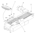
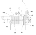
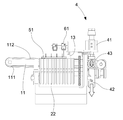
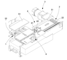
도1은 본 고안의 입체외관도이다.
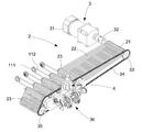
도2는 본 고안의 국부 입체외관도이다.
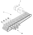
도3은 본 고안의 또 다른 하나의 국부 입체외관도이다.
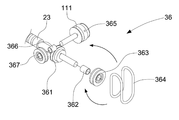
도4는 본 고안 중 연동유닛의 국부 입체분해도이다.
도5는 본 고안 중 연동유닛의 국부 입체 동작을 나타낸 사시도이다.
도6는 본 고안의 자재공급의 사시도이다.
도7은 본 고안의 자재공급 후, 승강장치가 자재공급장치의 높이를 낮추는 과정을 나타낸 사시도이다.
도8은 본 고안의 연속으로 자재를 공급하는 것을 나타낸 입체 사시도이다.1 is a stereoscopic view of the present invention.
Figure 2 is a local stereoscopic appearance of the present invention.
3 is another local stereoscopic view of the present invention.
Figure 4 is a local stereoscopic exploded view of the interlocking unit of the present invention.
Figure 5 is a perspective view showing a local three-dimensional operation of the interlocking unit of the present invention.
6 is a perspective view of a material supply of the present invention.
Figure 7 is a perspective view showing a process of lowering the height of the material supply device, the lifting device after the material supply of the present invention.
8 is a three-dimensional perspective view showing the supply of materials in a continuous manner of the present invention.
도면과 실시예를 통해 본 발명에 관한 더욱 상세한 설명을 하면 아래와 같다. BRIEF DESCRIPTION OF THE DRAWINGS Fig.
도1, 도2, 도3, 도4, 도5, 도6의 내용을 참조해 보면, 본 고안인 운송장치는 자재공급장치(1), 운송장치(2), 구동장치(3), 승강장치(4)를 포함하고 있다. 그 중 상기 자재공급장치(1)와 상기 운송장치(2)는 전향 관계를 이루고 있으며, 또한 상기 단일 구동장치(3)는 동시에 자재공급장치(1)와 운송장치(2)를 연동시킬 수 있고, 상기 승강장치(4)는 상기 자재공급장치(1)의 높이를 낮출 수 있다.Referring to the contents of Figs. 1, 2, 3, 4, 5, and 6, the transportation device of the present invention is a
상술된 상기 자재공급장치(1)는 복수 세트의 자재공급유닛(11)을 갖추고 있고, 상기 각 자재공급유닛(11)은 최소한 양롤러(111)와 운송벨트(112)를 갖추고 있으며, 상기 운송벨트(112)는 양롤러(111) 사이를 감아서 움직이며, 각 바퀴(111)들은 적당한 위치에 고정된다. 상기 자재공급장치(1) 말단에는 걸림판(12)이 더 설치되며, 상기 걸림판(12) 하측, 운송벨트(112)의 한 말단 주변에는 복수 개의 걸림롤러(13)가 설치된다.The
상기 운송장치(2)는 주동운송축바퀴(21), 복수 개의 운송벨트(22)와 복수 개의 종동축바퀴(23)를 포함하고 있으며, 상기 복수 개의 운송벨트(22)는 주동운송축바퀴(21)와 복수 개의 종동축바퀴(23) 사이를 감아서 움직이며, 또한 상기 각 주동운송축바퀴(21)와 각 복수 개의 종동축바퀴(23)는 평행 관계를 형성하게 된다. 그 중 상기 종동축바퀴(23)는 고저가 서로 교차되는 형태로 배치된다.The
상기 구동장치(3)는 모터(31)를 포함하고 있으며, 상기 모터(31)는 출력축(32)을 갖추고 있고, 상기 출력축(32)과 운송장치(2)의 주동운송축바퀴(21)는 축연결을 한 상태로 연동되며, 또한 상기 주동운송축바퀴(21)의 다른 하나의 대응되는 말단에는 제1기어판(33)이 설치되고, 상기 제1기어판(33)에는 체인(34)이 연결 설치되며, 상기 체인(34)은 복수 개의 종동기어판(35)을 감는 형태로 연동되며, 상기 종동기어판(35)들은 일부 종동축바퀴(23)의 한 끝에 연결 설치된다. 또한 상기 구동장치(3)는 복수 개의 연동유닛(36)을 포함하고 있으며, 상기 연동유닛(36)은 운송장치(2)와 자재공급장치(1)가 모두 구동장치(3)의 연동과 제어를 받을 수 있게 한다. 상기 연동유닛(36)은 제1바퀴(361), 제2바퀴(363),제3바퀴(365), 제4바퀴(367), 연동벨트(364)를 포함하고 있으며, 그 중 상기 제1바퀴(361)은 종동축바퀴(23)에 의해 관통되어지며, 상기 종동축바퀴(23) 외부단은 제2바퀴(363)를 관통하게 된다. 상기 제3바퀴(365)와 제4바퀴(367), 제2바퀴(363)는 직각 관계를 형성하게 되고, 상기 연동벨트(364)가 상기 제2바퀴(363)와 제3바퀴(365), 제4바퀴(367) 사이를 감아서 움직이게 된다.The
상기 승강장치(4)는 상기 자재공급장치(1) 내 말단 주변에 설치되며, 동력기통(41)와 승강받침(42)을 포함하고 있고, 상기 동력기통(41)은 상기 승강받침(42)을 연동하여 상하 운동을 할 수 있게 하고, 상기 승강받침(42)과 상기 자재공급장치(1) 내측단은 서로 연결되어 있으며, 상기 승강장치(4) 또한 승강바퀴(43)를 포함하고 있고, 상기 자재공급장치(1)의 운송벨트(112)는 상기 양롤러(111) 사이를 감아서 움직임과 동시에 승강바퀴(43) 상을 감아서 움직이게 된다.The
본 고안에는 또한 필요에 따라 센서(61, 62)를 설치하여 자재의 위치를 파악할 수 있으며, 이를 통해 승강장치(4)의 동작 시기를 제어할 수 있게 된다. In the present invention, it is also possible to determine the position of the material by installing the sensors (61, 62) as needed, through which it is possible to control the operation timing of the lifting device (4).
본 고안의 동작 원리는 구동장치(3)의 모터(31) 작동하면, 출력축(32)과 주동운송축바퀴(21)을 연동 시켜 회전하게 하고, 이를 통해 제1기어판(33)이 회전되면서 체인(34)을 연동 회전 시키게 되며, 이어서 각 종동기어판(35)이 회전하게 된다. 이어서 각 종동축바퀴(23)가 연동되어 회전하게 되며, 복수 개의 운송벨트(22)가 이에 따라 작동을 하게 된다. 또한 연동유닛(36)을 설치하여 종동축바퀴(23)이 회전할 때, 제1바퀴(361)와 제2바퀴(363), 연동벨트(364)가 회전되고 이어서 제3바퀴(365)와 제4바퀴(367)가 회전하게 된다. 이어서 바퀴(111)들이 회전하면서 운송벨트(112)를 회전시키게 되고, 이러한 과정을 통해 단일 구동장치(3)를 이용해 동시에 자재공급장치(1)와 운송장치(2)를 연동하여 작동할 수 있게 된다.The operating principle of the present invention is that when the
도6, 도7, 도8의 내용을 참조해 보면, 자재(51)가 수송대(52)를 통해 들어온 후, 우선 자재(51)를 자재공급장치(1) 상에 올리게 되고, 운송벨트(112)에 의해 운송되며, 이때 자재(51)가 걸림롤러(13)과 접촉할 때까지 운송이 되어진다. 또한 센서(61, 62)를 함께 사용하게 되는 경우, 승강장치(4)의 동력기통(41)의 승강받침(42)을 연동시켜 아래로 이동하게 하며, 그 결과 승강바퀴(43)의 높이를 낮출 수 있게 되어 자재공급장치(1)의 한 쪽이 낮아지게 되고, 자재(51)가 운송벨트(22)와 접촉할 수 있게 된다. 마지막으로 운송벨트(22)을 통해 전향되며 운송되어진다.6, 7 and 8, after the
이상 상술된 내용은 단지 본 고안의 특징과 장점 등을 상세히 설명하기 위해 비교적 우수한 실시예를 예로 들어 설명한 것으로 본 고안 청구범위는 이에 국한되지 않고 본 고안의 정신과 범주를 벗어나지 않는 범위 내에서 변경 및 기타 변형 등의 과정을 통한 경우에도 본 고안의 청구범위에 모두 포함된다.It is to be understood that both the foregoing general description and the following detailed description are exemplary and explanatory only and are not restrictive of the invention, as claimed, and it is to be understood that changes and variations may be made without departing from the spirit and scope of the invention. And variations are included in the claims of the present invention.
1: 자재공급장치 11:자재공급유닛 111:양롤러
112: 운송벨트 12: 걸림판 13: 걸림롤러
2: 운송장치 21: 주동운송축바퀴 22: 운송벨트
23: 종동축바퀴 3: 구동장치 31: 모터
32: 출력축 33: 제1기어판 34: 체인
35: 종동기어판 36: 연동유닛 361: 제1바퀴
362: 축부품 363: 제2바퀴 364: 연동벨트
365: 제3바퀴 366: 축부품 367: 제4바퀴
4: 승강장치 41: 동력기통 42: 승강받침
43: 승강바퀴 51: 자재 52: 수송대
61, 62: 센서 1: Material supply device 11: Material supply unit 111: Both rollers
112: transport belt 12: jam plate 13: jam roller
2: transport device 21: main transport wheel 22: transport belt
23: driven wheel 3: drive 31: motor
32: output shaft 33: first gear plate 34: chain
35: driven gear plate 36: linkage unit 361: first wheel
362: shaft component 363: second wheel 364: interlocking belt
365: third wheel 366: shaft part 367: fourth wheel
4: lifting device 41: power cylinder 42: lifting support
43: lift wheel 51: material 52: transport
61, 62: sensor
Claims (5)
상기 자재공급장치는 복수 세트의 자재공급유닛을 갖고, 복수 세트의 자재공급유닛 각각은 양롤러와 운송벨트를 갖고, 상기 운송벨트는 상기 양롤러 사이를 감아서 움직이며,
상기 운송장치는 주동운송축바퀴, 복수 개의 운송벨트와 복수 개의 종동축바퀴를 포함하며, 상기 복수 개의 운송벨트는 상기 주동운송축바퀴와 상기 복수 개의 종동축바퀴 사이를 감아서 움직이며, 상기 주동운송축바퀴와 상기 복수 개의 종동축바퀴는 평행 관계를 형성하고, 상기 복수 개의 종동축바퀴는 고저가 서로 교차하는 형태로 배치되며,
상기 구동장치는 모터를 포함하며, 상기 모터는 출력축을 갖고, 상기 출력축과 상기 운송장치의 주동운송축바퀴는 축연결을 한 상태로 연동되며, 상기 주동운송축바퀴의 다른 하나의 대응되는 말단에는 제1기어판이 설치되고, 상기 제1기어판에는 체인이 연결 설치되며, 상기 체인은 복수 개의 종동기어판을 감는 형태로 연동되며, 상기 복수 개의 종동기어판들은 일부 종동축바퀴의 한 끝에 연결 설치되고, 상기 구동장치는 복수 개의 연동 유닛을 더 포함하고, 상기 복수 개의 연동유닛은 상기 운송장치와 상기 자재공급장치가 상기 구동장치의 연동과 제어를 받을 수 있게 하는 것을 특징으로 하는 운송장치. It includes a material supply device, a transportation device, a driving device,
The material supply apparatus has a plurality of sets of material supply unit, each of the plurality of sets of material supply unit has both rollers and a transport belt, the transport belt is wound around the two rollers,
The transport apparatus includes a main transport shaft wheel, a plurality of transport belts and a plurality of driven shaft wheels, the plurality of transport belts are wound around the main transport shaft wheel and the plurality of driven shaft wheels, the main transport shaft wheel And the plurality of driven shaft wheels form a parallel relationship, and the plurality of driven shaft wheels are arranged in such a manner that the heights cross each other.
The drive device includes a motor, the motor has an output shaft, the output shaft and the main transport shaft wheel of the transport device is interlocked with the shaft connected, the other corresponding end of the main transport shaft wheel a first Gear plate is installed, the first gear plate is connected to the chain is installed, the chain is interlocked in the form of winding a plurality of driven gear plate, the plurality of driven gear plate is connected to one end of some driven shaft wheel, The driving device further comprises a plurality of interlocking units, wherein the plurality of interlocking units is characterized in that the transport device and the material supply device to be interlocked and controlled by the drive device.
Applications Claiming Priority (2)
| Application Number | Priority Date | Filing Date | Title |
|---|---|---|---|
| TW101213995 | 2012-07-20 | ||
| TW101213995U TWM445573U (en) | 2012-07-20 | 2012-07-20 | Delivery device |
Publications (1)
| Publication Number | Publication Date |
|---|---|
| KR20140000670U true KR20140000670U (en) | 2014-02-03 |
Family
ID=48091246
Family Applications (1)
| Application Number | Title | Priority Date | Filing Date |
|---|---|---|---|
| KR2020130004587U Ceased KR20140000670U (en) | 2012-07-20 | 2013-06-07 | Delivery device |
Country Status (4)
| Country | Link |
|---|---|
| JP (1) | JP3185447U (en) |
| KR (1) | KR20140000670U (en) |
| CN (1) | CN203411047U (en) |
| TW (1) | TWM445573U (en) |
Families Citing this family (10)
| Publication number | Priority date | Publication date | Assignee | Title |
|---|---|---|---|---|
| CN104261109A (en) * | 2014-09-19 | 2015-01-07 | 上海睿丰自动化系统有限公司 | Belt type heavy transport machine |
| CN104495269A (en) * | 2014-12-19 | 2015-04-08 | 苏州互强工业设备有限公司 | Automatic assembly line |
| CN111688984A (en) * | 2020-06-16 | 2020-09-22 | 湖北天永智能装备有限公司 | Automatic piece mounting device for blocky curvy production line |
| CN112643550B (en) * | 2020-12-30 | 2024-11-29 | 江苏凯伦铝业有限公司 | Sand blasting system for sand blasting of aluminum profile |
| CN113291768A (en) * | 2021-05-24 | 2021-08-24 | 武汉理工大学 | Full-automatic bag arranging machine |
| CN113427911B (en) * | 2021-06-24 | 2023-04-14 | 宁波市第一医院 | A two-mode automatic page numbering device for file arrangement |
| CN113920646A (en) * | 2021-10-13 | 2022-01-11 | 桂林电子科技大学 | Custom-made vending machine for solar term fruit and vegetable health preservation |
| CN115072315B (en) * | 2022-07-20 | 2023-11-21 | 徐州瑞控机电科技有限公司 | Coal mine belt conveying system based on AI image processing technology |
| CN116945473B (en) * | 2023-08-04 | 2024-02-23 | 河源市皓吉达通讯器材有限公司 | Multilayer metal insert molding product preparation device |
| CN119822002B (en) * | 2025-03-17 | 2025-06-10 | 肇庆市将军陶瓷有限公司 | A large-scale ceramic rock plate embryo correction synchronous detection feeding device and process |
-
2012
- 2012-07-20 TW TW101213995U patent/TWM445573U/en not_active IP Right Cessation
-
2013
- 2013-06-06 JP JP2013003210U patent/JP3185447U/en not_active Expired - Fee Related
- 2013-06-06 CN CN201320324020.5U patent/CN203411047U/en not_active Expired - Fee Related
- 2013-06-07 KR KR2020130004587U patent/KR20140000670U/en not_active Ceased
Also Published As
| Publication number | Publication date |
|---|---|
| TWM445573U (en) | 2013-01-21 |
| JP3185447U (en) | 2013-08-15 |
| CN203411047U (en) | 2014-01-29 |
Similar Documents
| Publication | Publication Date | Title |
|---|---|---|
| CN104058241B (en) | Multilamellar intercommunication roller shutter jacking equipment | |
| JP3185447U (en) | Conveyor equipment | |
| CN203845469U (en) | Paper pass box stacking and un-stacking device for automated verification system of electric energy meter | |
| CN107472932A (en) | Carloader and loading system | |
| CN204433753U (en) | A kind of motor pendulum driving wheel sorter | |
| CN103057943A (en) | Transverse hoist | |
| CN108974757A (en) | Jacking mechanism and roller conveying line | |
| CN207957007U (en) | A kind of pallet lift solid automatic conveying device | |
| CN105083902A (en) | Ground-type roller conveying mechanism suitable for floor slab arrangement | |
| JP2017197295A (en) | Conveyance system | |
| CN205023280U (en) | Intensive large -scale commodity circulation intelligence automatic storage storehouse | |
| CN204777149U (en) | Continuous type lift | |
| CN210117040U (en) | Goods transfer frame | |
| CN206871959U (en) | A kind of intelligent conveying device | |
| CN105129320A (en) | Vertical type continuous circulation carrying assistance freight transport elevator | |
| CN202542445U (en) | Steering transmission mechanism of container component | |
| CN208964467U (en) | A kind of lifting floor truck | |
| JP2015178396A (en) | Portal transportation storage apparatus and automatic storage/take-out type material storehouse | |
| CN205708378U (en) | Facilitate implementation the Wall or floor tile warehousing system of automatization's access | |
| KR101489271B1 (en) | Package delivery apparatus | |
| CN205589911U (en) | Yardage roll conveyor of cloth machine is spread to multilayer | |
| CN204727039U (en) | One bleachinges and dyeing the removable transmitting device of knit goods | |
| CN202208625U (en) | Hydraulic lifting platform of hydraulic control system | |
| CN205087588U (en) | Automatic setting machine layer brick handling pile up neatly device | |
| CN211337486U (en) | A pipe conveying device |
Legal Events
| Date | Code | Title | Description |
|---|---|---|---|
| UA0108 | Application for utility model registration |
Comment text: Application for Utility Model Registration Patent event code: UA01011R08D Patent event date: 20130607 |
|
| UG1501 | Laying open of application | ||
| A201 | Request for examination | ||
| UA0201 | Request for examination |
Patent event date: 20151224 Patent event code: UA02012R01D Comment text: Request for Examination of Application Patent event date: 20130607 Patent event code: UA02011R01I Comment text: Application for Utility Model Registration |
|
| E902 | Notification of reason for refusal | ||
| UE0902 | Notice of grounds for rejection |
Comment text: Notification of reason for refusal Patent event code: UE09021S01D Patent event date: 20161214 |
|
| E601 | Decision to refuse application | ||
| UE0601 | Decision on rejection of utility model registration |
Comment text: Decision to Refuse Application Patent event code: UE06011S01D Patent event date: 20170216 |