KR20130108977A - Device and method for storing products - Google Patents
Device and method for storing products Download PDFInfo
- Publication number
- KR20130108977A KR20130108977A KR20127030573A KR20127030573A KR20130108977A KR 20130108977 A KR20130108977 A KR 20130108977A KR 20127030573 A KR20127030573 A KR 20127030573A KR 20127030573 A KR20127030573 A KR 20127030573A KR 20130108977 A KR20130108977 A KR 20130108977A
- Authority
- KR
- South Korea
- Prior art keywords
- guide element
- product
- receptacle
- component
- filling level
- Prior art date
Links
Images


Classifications
-
- B—PERFORMING OPERATIONS; TRANSPORTING
- B01—PHYSICAL OR CHEMICAL PROCESSES OR APPARATUS IN GENERAL
- B01F—MIXING, e.g. DISSOLVING, EMULSIFYING OR DISPERSING
- B01F23/00—Mixing according to the phases to be mixed, e.g. dispersing or emulsifying
- B01F23/40—Mixing liquids with liquids; Emulsifying
- B01F23/49—Mixing systems, i.e. flow charts or diagrams
-
- B—PERFORMING OPERATIONS; TRANSPORTING
- B65—CONVEYING; PACKING; STORING; HANDLING THIN OR FILAMENTARY MATERIAL
- B65D—CONTAINERS FOR STORAGE OR TRANSPORT OF ARTICLES OR MATERIALS, e.g. BAGS, BARRELS, BOTTLES, BOXES, CANS, CARTONS, CRATES, DRUMS, JARS, TANKS, HOPPERS, FORWARDING CONTAINERS; ACCESSORIES, CLOSURES, OR FITTINGS THEREFOR; PACKAGING ELEMENTS; PACKAGES
- B65D25/00—Details of other kinds or types of rigid or semi-rigid containers
-
- B—PERFORMING OPERATIONS; TRANSPORTING
- B01—PHYSICAL OR CHEMICAL PROCESSES OR APPARATUS IN GENERAL
- B01F—MIXING, e.g. DISSOLVING, EMULSIFYING OR DISPERSING
- B01F23/00—Mixing according to the phases to be mixed, e.g. dispersing or emulsifying
- B01F23/40—Mixing liquids with liquids; Emulsifying
- B01F23/43—Mixing liquids with liquids; Emulsifying using driven stirrers
-
- B—PERFORMING OPERATIONS; TRANSPORTING
- B01—PHYSICAL OR CHEMICAL PROCESSES OR APPARATUS IN GENERAL
- B01F—MIXING, e.g. DISSOLVING, EMULSIFYING OR DISPERSING
- B01F23/00—Mixing according to the phases to be mixed, e.g. dispersing or emulsifying
- B01F23/50—Mixing liquids with solids
- B01F23/53—Mixing liquids with solids using driven stirrers
-
- B—PERFORMING OPERATIONS; TRANSPORTING
- B01—PHYSICAL OR CHEMICAL PROCESSES OR APPARATUS IN GENERAL
- B01F—MIXING, e.g. DISSOLVING, EMULSIFYING OR DISPERSING
- B01F23/00—Mixing according to the phases to be mixed, e.g. dispersing or emulsifying
- B01F23/50—Mixing liquids with solids
- B01F23/59—Mixing systems, i.e. flow charts or diagrams
-
- B—PERFORMING OPERATIONS; TRANSPORTING
- B01—PHYSICAL OR CHEMICAL PROCESSES OR APPARATUS IN GENERAL
- B01F—MIXING, e.g. DISSOLVING, EMULSIFYING OR DISPERSING
- B01F25/00—Flow mixers; Mixers for falling materials, e.g. solid particles
-
- B—PERFORMING OPERATIONS; TRANSPORTING
- B01—PHYSICAL OR CHEMICAL PROCESSES OR APPARATUS IN GENERAL
- B01F—MIXING, e.g. DISSOLVING, EMULSIFYING OR DISPERSING
- B01F25/00—Flow mixers; Mixers for falling materials, e.g. solid particles
- B01F25/50—Circulation mixers, e.g. wherein at least part of the mixture is discharged from and reintroduced into a receptacle
- B01F25/54—Circulation mixers, e.g. wherein at least part of the mixture is discharged from and reintroduced into a receptacle provided with a pump inside the receptacle to recirculate the material within the receptacle
-
- B—PERFORMING OPERATIONS; TRANSPORTING
- B01—PHYSICAL OR CHEMICAL PROCESSES OR APPARATUS IN GENERAL
- B01F—MIXING, e.g. DISSOLVING, EMULSIFYING OR DISPERSING
- B01F27/00—Mixers with rotary stirring devices in fixed receptacles; Kneaders
- B01F27/80—Mixers with rotary stirring devices in fixed receptacles; Kneaders with stirrers rotating about a substantially vertical axis
- B01F27/86—Mixers with rotary stirring devices in fixed receptacles; Kneaders with stirrers rotating about a substantially vertical axis co-operating with deflectors or baffles fixed to the receptacle
- B01F27/861—Mixers with rotary stirring devices in fixed receptacles; Kneaders with stirrers rotating about a substantially vertical axis co-operating with deflectors or baffles fixed to the receptacle the baffles being of cylindrical shape, e.g. a mixing chamber surrounding the stirrer, the baffle being displaced axially to form an interior mixing chamber
-
- B—PERFORMING OPERATIONS; TRANSPORTING
- B01—PHYSICAL OR CHEMICAL PROCESSES OR APPARATUS IN GENERAL
- B01F—MIXING, e.g. DISSOLVING, EMULSIFYING OR DISPERSING
- B01F35/00—Accessories for mixers; Auxiliary operations or auxiliary devices; Parts or details of general application
- B01F35/20—Measuring; Control or regulation
- B01F35/21—Measuring
- B01F35/211—Measuring of the operational parameters
- B01F35/2112—Level of material in a container or the position or shape of the upper surface of the material
-
- B—PERFORMING OPERATIONS; TRANSPORTING
- B01—PHYSICAL OR CHEMICAL PROCESSES OR APPARATUS IN GENERAL
- B01F—MIXING, e.g. DISSOLVING, EMULSIFYING OR DISPERSING
- B01F2101/00—Mixing characterised by the nature of the mixed materials or by the application field
- B01F2101/06—Mixing of food ingredients
- B01F2101/07—Mixing ingredients into milk or cream, e.g. aerating
-
- B—PERFORMING OPERATIONS; TRANSPORTING
- B01—PHYSICAL OR CHEMICAL PROCESSES OR APPARATUS IN GENERAL
- B01F—MIXING, e.g. DISSOLVING, EMULSIFYING OR DISPERSING
- B01F2101/00—Mixing characterised by the nature of the mixed materials or by the application field
- B01F2101/06—Mixing of food ingredients
- B01F2101/14—Mixing of ingredients for non-alcoholic beverages; Dissolving sugar in water
-
- B—PERFORMING OPERATIONS; TRANSPORTING
- B01—PHYSICAL OR CHEMICAL PROCESSES OR APPARATUS IN GENERAL
- B01F—MIXING, e.g. DISSOLVING, EMULSIFYING OR DISPERSING
- B01F23/00—Mixing according to the phases to be mixed, e.g. dispersing or emulsifying
- B01F23/02—Maintaining the aggregation state of the mixed materials
- B01F23/023—Preventing sedimentation, conglomeration or agglomeration of solid ingredients during or after mixing by maintaining mixed ingredients in movement
-
- Y—GENERAL TAGGING OF NEW TECHNOLOGICAL DEVELOPMENTS; GENERAL TAGGING OF CROSS-SECTIONAL TECHNOLOGIES SPANNING OVER SEVERAL SECTIONS OF THE IPC; TECHNICAL SUBJECTS COVERED BY FORMER USPC CROSS-REFERENCE ART COLLECTIONS [XRACs] AND DIGESTS
- Y10—TECHNICAL SUBJECTS COVERED BY FORMER USPC
- Y10T—TECHNICAL SUBJECTS COVERED BY FORMER US CLASSIFICATION
- Y10T137/00—Fluid handling
- Y10T137/0318—Processes
-
- Y—GENERAL TAGGING OF NEW TECHNOLOGICAL DEVELOPMENTS; GENERAL TAGGING OF CROSS-SECTIONAL TECHNOLOGIES SPANNING OVER SEVERAL SECTIONS OF THE IPC; TECHNICAL SUBJECTS COVERED BY FORMER USPC CROSS-REFERENCE ART COLLECTIONS [XRACs] AND DIGESTS
- Y10—TECHNICAL SUBJECTS COVERED BY FORMER USPC
- Y10T—TECHNICAL SUBJECTS COVERED BY FORMER US CLASSIFICATION
- Y10T137/00—Fluid handling
- Y10T137/8158—With indicator, register, recorder, alarm or inspection means
-
- Y—GENERAL TAGGING OF NEW TECHNOLOGICAL DEVELOPMENTS; GENERAL TAGGING OF CROSS-SECTIONAL TECHNOLOGIES SPANNING OVER SEVERAL SECTIONS OF THE IPC; TECHNICAL SUBJECTS COVERED BY FORMER USPC CROSS-REFERENCE ART COLLECTIONS [XRACs] AND DIGESTS
- Y10—TECHNICAL SUBJECTS COVERED BY FORMER USPC
- Y10T—TECHNICAL SUBJECTS COVERED BY FORMER US CLASSIFICATION
- Y10T137/00—Fluid handling
- Y10T137/8593—Systems
- Y10T137/85978—With pump
- Y10T137/86035—Combined with fluid receiver
Abstract
방법 및 장치는 리셉터클 내에 제품을 저장하기 위하여 사용된다. 제품은 제1 액체 성분 및 적어도 제2 성분으로 구성된다. 리셉터클 내에서, 제품은 리셉터클 내에 배열된 관형 가이드 요소의 영역에 배치되는 이송 장치에 의해 순환한다. 리셉터클에 공급된 제품의 하나 이상의 성분은 가이드 요소의 내부 공간 내로 유동한다.The method and apparatus are used to store a product in a receptacle. The product consists of a first liquid component and at least a second component. Within the receptacle, the product is circulated by a conveying device disposed in the region of the tubular guide element arranged in the receptacle. One or more components of the product supplied to the receptacle flow into the interior space of the guide element.
Description
본 발명은 제1 액체 성분과 적어도 제2 성분으로 구성되는 제품을 저장하기 위한 리셉터클을 포함하는 장치에 관한 것으로서, 수직 성분으로 종방향 축을 따라 배향된 관형 가이드 요소는 기저로부터 이격된 상태로 리셉터클 내에 배열되고, 제품을 위한 이송 장치는 가이드 요소의 영역 내에 배열된다. The present invention relates to an apparatus comprising a receptacle for storing a product consisting of a first liquid component and at least a second component, wherein the tubular guide element oriented along the longitudinal axis with the vertical component is spaced apart from the base in the receptacle. And a conveying device for the product is arranged in the region of the guide element.
본 발명은 또한 리셉터클 내에 제품을 저장하기 위한 방법에 관한 것으로, 제품은 제1 액체 성분과 적어도 제2 성분으로 구성되고, 제품은 리셉터클 내에 배열된 관형 가이드 요소의 영역에 배치된 이송 장치에 의해 리셉터클 내에서 순환한다.
The invention also relates to a method for storing a product in a receptacle, wherein the product consists of a first liquid component and at least a second component, the product being receptacle by a conveying device disposed in the region of the tubular guide element arranged in the receptacle. Circulate within.
이러한 제품은 예를 들어, 식품일 수 있다. 예를 들어, 또한 제2 성분은 액체일 수 있다. 이러한 성분을 포함하는 제품의 예시는 유제(emulsion), 특히 우유이다. 또 다른 대안예에 따라서, 제2 성분은 고상이다. 이는 예를 들어, 과일 조작을 포함하는 주스의 경우일 수 있다. 그 외의 다른 예시는 코코넛 프레이크를 포함한 우유, 시리얼을 포함한 우유 및 덩어리 함유물을 포함한 수프 및 소스이다. 덩어리 함유물은 예를 들어 과일 및/또는 육류일 수 있다.Such a product may for example be a food. For example, the second component can also be a liquid. An example of a product comprising such ingredients is an emulsion, in particular milk. According to another alternative, the second component is a solid phase. This may be the case, for example, for juices comprising fruit manipulations. Other examples are soups and sauces, including milk with coconut flakes, milk and cereals, including cereals. The lump content may for example be fruit and / or meat.
제2 성분이 고상일 때, 제2 성분은 전형적으로 입자의 형태를 가지며, 이들 입자의 평균 직경은 1 mm 내지 40 mm의 범위 내에 있다. 특정 경우에, 더 작거나 또는 더 큰 직경도 또한 가능하다.When the second component is in the solid phase, the second component typically has the form of particles, and the average diameter of these particles is in the range of 1 mm to 40 mm. In certain cases, smaller or larger diameters are also possible.
적어도 두 제품으로 구성되는 제품을 저장하려고 할 때, 제2 성분이 제1 성분 내에서 균일하게 분포되지 않고 분리 현상이 발생될 수 있는 문제점이 야기된다. 제1 및 제2 성분의 특정 중량에 따라, 한편 입자들은 부유하거나 다른 한편으로는 정착될 수 있다.
When trying to store a product consisting of at least two products, a problem arises in which a separation phenomenon can occur without the second component being uniformly distributed within the first component. Depending on the specific weight of the first and second components, on the one hand the particles may be suspended or settle on the other.
따라서, 본 발명의 목적은 성분들의 분리가 방지되도록 전술된 유형의 장치를 구성하는 데 있다. It is therefore an object of the present invention to construct an apparatus of the type described above such that the separation of components is prevented.
이 목적은 본 발명에 따라서 구현되는데, 제품의 하나 이상의 성분에 대한 하나 이상의 공급 라인이 가이드 요소 내로 개방된다. This object is achieved according to the invention, wherein one or more supply lines for one or more components of the product are opened into the guide element.
본 발명의 또 다른 목적은 성분들의 분리가 방지되도록 전술된 유형의 방법을 향상시키는 데 있다. It is a further object of the present invention to improve the method of the type described above so that the separation of the components is prevented.
이 목적은 본 발명에 따라 구현되는데, 리셉터클에 공급된 제품의 성분이 가이드 요소의 내부 공간 내로 유동한다. This object is achieved according to the invention, in which the components of the product supplied to the receptacle flow into the interior space of the guide element.
가이드 요소 내에서 유동 속도는 가이드 요소 내로 유동하는 제품에 의해 증가된다. 게다가, 제품을 공급하는 중에 발생되는 임의의 분리가 방지된다.The flow velocity in the guide element is increased by the product flowing into the guide element. In addition, any separation that occurs during the supply of the product is prevented.
또한, 제품의 평균 충전 수위로부터 가이드 요소의 간격이 제품의 원만한 순환은 제2 성분의 평균 입자 크기의 대략 1.3 배일 경우 제품을 원만히 순환하는데 도움이 된다. In addition, a smooth circulation of the product from the average fill level of the product to a smooth circulation of the product helps to smoothly circulate the product if it is approximately 1.3 times the average particle size of the second component.
특정 충전 수위는 충전 수준 측정 수단을 갖는 리셉터클에 의해 도움이 된다. The specific fill level is aided by a receptacle with a filling level measuring means.
특히, 충전 수위 측정 수단은 충전 수위 조절 수단에 연결되는 것이 제안된다. In particular, it is proposed that the filling level measuring means is connected to the filling level adjusting means.
제품의 유동을 위한 하나 이상의 지향 요소를 이송 장치에 인접하게 배열함으로써 유동 방향을 선택적으로 구체화하는데 도움이 된다. The arrangement of one or more directing elements for the flow of the product adjacent to the conveying device helps to selectively specify the flow direction.
제품의 특정 특성에 적합하도록, 이송 장치의 이송 방향이 상반되게 형성될 수 있다.To suit the particular characteristics of the product, the conveying direction of the conveying device may be formed oppositely.
공급된 제품 및 이미 존재하는 제품의 효과적인 혼합은 가이드 요소의 내부 공간 내로 유동하는 리셉터클 내에 공급된 제품에 의해 보조된다. 게다가 분리도 또한 효과적으로 방지된다. Effective mixing of the supplied product and the already existing product is assisted by the product supplied in the receptacle flowing into the interior space of the guide element. In addition, separation is also effectively prevented.
리셉터클 내에서 충전 수위의 측정은 선호되는 유동 형성에 기여한다.
Measurement of the filling level in the receptacle contributes to the preferred flow formation.
본 발명의 예시적인 실시 형태가 도면에 예시적으로 도시된다.
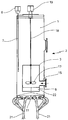
도 1은 잠긴 입자를 갖는 제품에 대한 실시 형태에서 장치의 수직 섹션 내에서 예시도.
도 2는 도 1에 대해 변형된 실시 형태를 도시하는 도면.
도 3은 상부로부터 하부까지 가이드 요소 내에서 유동 방향에 따른 도 2의 실시 형태를 도시하는 도면.
도 4는 역방향 유동에 따른 도 3의 장치를 도시하는 도면.
도 5는 장치의 또 다른 실시 형태의 수직 단면도.
도 6은 도 5의 절단선 VI-VI를 따른 단면도.Exemplary embodiments of the invention are shown by way of example in the drawings.
1 is an illustration within a vertical section of the device in an embodiment for a product having submerged particles.
FIG. 2 shows a modified embodiment of FIG. 1. FIG.
FIG. 3 shows the embodiment of FIG. 2 along the flow direction within the guide element from top to bottom.
4 shows the apparatus of FIG. 3 in reverse flow;
5 is a vertical sectional view of yet another embodiment of the device.
6 is a cross-sectional view taken along the line VI-VI of FIG. 5.
도 1에서의 예시적인 실시 형태에 따라서, 관형 가이드 요소(tubular guide element, 3)가 리셉터클(receptacle, 2)의 내부 공간(1) 내에 배열된다. 가이드 요소(3)는 종방향 축(4)을 따라 실질적으로 수직 방향으로 연장된다. 도시된 예시적인 실시 형태에서, 리셉터클(2)은 수평 단면 평면 내에 원형 윤곽을 가지며, 가이드 요소(3)는 리셉터클(2)의 내측에서 실질적으로 동축을 이루어 배열된다. According to the exemplary embodiment in FIG. 1, a
내부 공간(1)은 저장되는 제품(5)을 수용하기 위해 제공된다. 리셉터클(2) 내에서, 제품은 충전 수위(6)를 갖는다. 충전 수위 측정 장치(8)에 연결된 센서(7)가 충전 수위를 측정하기 위해 제공된다.The
예시적인 실시 형태에 따라서, 가이드 요소(3)는 수평 단면 평면 내에 원형 단면 영역을 가질 수 있다. 그러나, 그 외의 다른 원형 형태 또는 각진 형태의 단면 영역도 가질 수 있다. 가이드 요소(3)의 하부 단부(9)는 리셉터클(2)의 기저(11)로부터 간격을 이루어 배열된다. 도시된 예시적인 실시 형태에서, 하부 단부(9)의 영역에서 단면(12)이 넓어진다. 도 1은 또한 가이드 요소(3)의 상부 단부(13)의 영역에서 단면(14)이 넓어지는 것을 나타낸다. According to an exemplary embodiment, the
제품(5)을 위한 공급 파이프(15)는 가이드 요소(3) 내로 개방된다. 특히, 공급 라인(15)은 리셉터클(2)의 벽(16)의 영역에서 고정되고, 가이드 요소(3)는 공급 파이프(15)에 의해 보유 및 배치된다. The
제품(5)을 위한 이송 장치(17)가 가이드 요소(3)의 내측에 배열된다. 이송 장치(17)는 샤프트(18)에 의해 구동장치(19)에 결합되는 프로펠러의 형태를 가질 수 있다.A
도시된 예시적인 실시 형태에서, 기저(11)는 기저의 중심 영역이 기저(11)의 주변 영역보다 더 높은 높이에 배열되도록 윤곽(20)을 갖는다. 기저(11)는 이에 따라 가이드 요소(3)를 향하여 만곡된다.In the exemplary embodiment shown, the
도 1의 실시 형태는 가이드 요소(3)의 상부 단부(13) 아래에 있는 충전 수위(6)를 도시한다. 이 실시 형태는 정착된 입자의 경우 유용하다.The embodiment of FIG. 1 shows the
도 2의 실시 형태에서, 기저(11)의 영역에 배열된 복수의 충전 파이프(21)는 리셉터클(2)을 연계된 충전 장치에 연결한다. 또한, 도 2에 도시된 바와 같이, 가이드 요소(3)의 영역에 배열된 하나 이상의 안내 요소(22)가 가이드 요소(2) 내측에서 회전 유동의 형성을 억제하고, 종방향 축(4)의 방향으로 유동의 형성을 촉진한다. 예를 들어, 가이드 요소(3)의 외주에서 서로에 대해 120°로 각각 배열된 3개의 안내 요소(22)는 예를 들어, 가이드 요소(3)의 하부 단부(9)의 영역에 배열될 수 있다.In the embodiment of FIG. 2, a plurality of
도 3은 제품(5)이 부유하는 경향을 갖는 제2 성분(23)을 포함하는 실시 형태를 도시한다. 이는 예를 들어, 제1 성분보다 작은 비중을 갖는 제2 성분에 의해 구현된다. 이러한 제품(5)의 경우에, 가이드 요소(3) 내에서 상부로부터 하부로의 수직 이송 방향은 미리정해진다. 부유하는 제2 성분(23)은 이에 따라 가이드 요소(3) 내로 흡입되고, 여기서 제1 성분과 혼합된다. 내부 공간(1) 내의 충전 수위는 최대 구조적 높이의 대략 30%이다. 가이드 요소(3)의 상부 단부(13)는 충전 수위(6)로부터 간격(24)을 갖는다. 3 shows an embodiment in which the
도 3에 도시된 바와 같이 부유하는 입자의 경우에, 부유하는 입자가 내부에 흡입되고 이에 따라 혼합되는 것을 보장하기 위하여 가이드 요소의 상부 단부 위의 충전 수위(6)가 요구된다. 그러나, 간격(24)은 또한 흡입 효과가 그 뒤에 감소될 수 있을 정도로 크지 않아야 한다. In the case of suspended particles as shown in FIG. 3, a
도 4의 예시적인 실시 형태에서, 제품(5)이 저장되고, 이 제품의 제2 성분(23)은 정착되는 경향이 있다(settle). 이는 예를 들어, 제1 성분보다 큰 비중을 갖는 제2 성분(23)에 의해 야기될 수 있다. 이러한 제품(5)이 저장될 때, 가이드 요소(3) 내에서 하부로부터 상부로의 수직 이송 방향은 기저(11)의 영역에 정착되는 제2 성분(23)을 가이드 요소(3) 내로 흡인하고 그 뒤 제1 성분과 혼합시키기 위해 미리정해진다. In the exemplary embodiment of FIG. 4, the
도 5는 더 상세한 리셉터클(2)의 도면을 도시한다. 공급 파이프(15)에 의한 가이드 요소(3)의 지지 및 가이드 요소(3)의 형상이 구체적으로 재차 도시된다. 5 shows a more detailed view of the
도 6의 수평 단면으로부터 도시된 바와 같이, 도 5에 따르는 실시 형태에서, 가이드 요소(3)의 주변 방향으로 서로에 대해 각각 90°로 배열된 4개의 안내 요소(22)가 사용된다. 이 예시적인 실시 형태에서, 이송 장치(17)는 4개의 프로펠러 블레이드가 제공된다. As shown from the horizontal cross section of FIG. 6, in the embodiment according to FIG. 5, four
덩어리 함유물(chunky ingredient)을 갖는 제품(5)의 경우에, 간격(10)은 간격(10)이 평균 입자 크기의 1.3배이도록 전형적으로 치수가 형성된다. 이러한 치수 형성은 또한 간격(24)에 대해 유용한 것으로 입증되었다.In the case of
전형적인 실시 형태에서, 이송 장치(17)는 분당 대략 300 회로 회전한다. 구동장치(19)가 진동수를 제어하도록 설계될 수 있다.In a typical embodiment, the
가이드 요소(3)의 직경은 전형적으로 리셉터클(2)의 직경의 대략 0.2 내지 0.8배이다. 이는 각각의 경우 내부 직경으로 지칭된다. 대략 400 mm/초의 유동 속도는 전형적으로 가이드 요소(3) 내의 이송 장치(17)에 의해 생성된다.The diameter of the
전술된 리셉터클(2) 내에서의 수위의 변동(fluctuation)에 따라 특히 제품의 성분들 또는 제품의 연속적인 공급이 야기되고, 용기를 충전하기 위한 제품의 불연속ㅈ거인 제거가 야기될 수 있다.Fluctuations in the water level in the
제품의 적어도 두 가지의 성분이 개별적으로 공급될 때, 또한 성분들은 단지 리셉터클(2) 내에서 혼합될 수 있다. 제품의 개개의 성분들은 그 뒤에 전형적으로 각각의 개별 공급 파이프에 의해 공급된다. When at least two components of the product are supplied separately, the components can also only be mixed in the
또 다른 실시 형태에서, 가이드 요소(3)는 이의 종방향 부분을 따라 단면이 적어도 한 부분 좁아지고, 제품의 적어도 하나의 성분 또는 제품의 공급은 이 영역에서 제공된다. 혼합을 돕는 더 높은 유동 속도는 이 좁은 부분에 의해 형성된다.In another embodiment, the
Claims (16)
Applications Claiming Priority (3)
| Application Number | Priority Date | Filing Date | Title |
|---|---|---|---|
| DE102010023832.5 | 2010-06-10 | ||
| DE201010023832 DE102010023832A1 (en) | 2010-06-10 | 2010-06-10 | Device and method for storing products |
| PCT/DE2011/001054 WO2011153982A1 (en) | 2010-06-10 | 2011-05-05 | Device and method for storing products |
Related Child Applications (1)
| Application Number | Title | Priority Date | Filing Date |
|---|---|---|---|
| KR1020167028894A Division KR101760634B1 (en) | 2010-06-10 | 2011-05-05 | Device and method for storing products |
Publications (1)
| Publication Number | Publication Date |
|---|---|
| KR20130108977A true KR20130108977A (en) | 2013-10-07 |
Family
ID=44503453
Family Applications (2)
| Application Number | Title | Priority Date | Filing Date |
|---|---|---|---|
| KR20127030573A KR20130108977A (en) | 2010-06-10 | 2011-05-05 | Device and method for storing products |
| KR1020167028894A KR101760634B1 (en) | 2010-06-10 | 2011-05-05 | Device and method for storing products |
Family Applications After (1)
| Application Number | Title | Priority Date | Filing Date |
|---|---|---|---|
| KR1020167028894A KR101760634B1 (en) | 2010-06-10 | 2011-05-05 | Device and method for storing products |
Country Status (17)
| Country | Link |
|---|---|
| US (1) | US10737837B2 (en) |
| EP (1) | EP2579969B1 (en) |
| JP (1) | JP6082694B2 (en) |
| KR (2) | KR20130108977A (en) |
| CN (1) | CN103002978B (en) |
| AU (1) | AU2011264179B2 (en) |
| BR (1) | BR112012031386B1 (en) |
| CA (1) | CA2799799A1 (en) |
| DE (1) | DE102010023832A1 (en) |
| EA (1) | EA025585B1 (en) |
| ES (1) | ES2545507T3 (en) |
| MX (1) | MX2012014185A (en) |
| PL (1) | PL2579969T3 (en) |
| TN (1) | TN2012000545A1 (en) |
| TW (1) | TWI551515B (en) |
| WO (1) | WO2011153982A1 (en) |
| ZA (1) | ZA201208716B (en) |
Families Citing this family (1)
| Publication number | Priority date | Publication date | Assignee | Title |
|---|---|---|---|---|
| US11123698B2 (en) | 2017-06-21 | 2021-09-21 | Alfa Laval Corporate Ab | Fluid handling apparatus and fluid tank system |
Family Cites Families (33)
| Publication number | Priority date | Publication date | Assignee | Title |
|---|---|---|---|---|
| US1371610A (en) * | 1914-09-29 | 1921-03-15 | Samuel M Dungan | Screw-propeller |
| US2244902A (en) * | 1937-12-23 | 1941-06-10 | Stich Eugen | Process for the automatic cultivation of yeast |
| US2293183A (en) * | 1939-04-03 | 1942-08-18 | American Well Works | Mixing turbine |
| GB548664A (en) | 1941-04-16 | 1942-10-20 | Electro Chem Eng | Improvements in or relating to apparatus for aerating liquids |
| DE1181673B (en) | 1960-06-24 | 1964-11-19 | Thaelmann Schwermaschbau Veb | Device for aerating a liquid |
| JPS4952164U (en) * | 1972-08-09 | 1974-05-09 | ||
| US3804255A (en) * | 1972-10-18 | 1974-04-16 | R Speece | Recycling gas contact apparatus |
| US4207180A (en) * | 1979-01-11 | 1980-06-10 | Chang Shih Chih | Gas-liquid reaction method and apparatus |
| US4242199A (en) * | 1979-05-18 | 1980-12-30 | Richards Of Rockford, Inc. | Aerator apparatus |
| US4328175A (en) * | 1979-10-02 | 1982-05-04 | Union Carbide Corporation | Apparatus for contacting a liquid with a gas |
| JPS5817615Y2 (en) * | 1980-03-26 | 1983-04-09 | 荏原インフイルコ・エンジニアリング・サ−ビス株式会社 | Suspension granulation separation concentration equipment |
| JP2739320B2 (en) * | 1988-03-11 | 1998-04-15 | 日本ソリッド株式会社 | Polluted water flocculation equipment |
| EP0558595A4 (en) * | 1990-11-08 | 1993-11-03 | The Dow Chemical Company | Reactor with foam shearing means for solution polymerization process |
| CN2080420U (en) * | 1990-12-26 | 1991-07-10 | 上海市化工装备研究所 | High-efficiency homogeneous crusher |
| JP3161734B2 (en) * | 1991-12-02 | 2001-04-25 | テクノロジカル リソーシィズ プロプライエタリー リミテッド | Reactor |
| JPH0672605U (en) * | 1993-03-29 | 1994-10-11 | 栗田工業株式会社 | Coagulating sedimentation equipment |
| US5451348A (en) | 1994-04-18 | 1995-09-19 | Praxair Technology, Inc. | Variable liquid level eductor/impeller gas-liquid mixing apparatus and process |
| JP3725202B2 (en) * | 1994-05-11 | 2005-12-07 | プラクスエア・テクノロジー・インコーポレイテッド | Enhanced oxidation of organic chemicals |
| TW283095B (en) * | 1995-07-25 | 1996-08-11 | Praxair Technology Inc | An improved system for the mixing of gases and liquids |
| FR2758094B1 (en) * | 1997-01-08 | 1999-03-26 | Alain Boulant | DEVICE FOR BREWING AND AERATING A LIQUID AND FOR REMOVING FOAM IN A LIQUID TREATMENT TANK |
| US5916491A (en) * | 1997-01-16 | 1999-06-29 | Rhone-Poulenc, Inc. | Gas-liquid vortex mixer and method |
| FR2763867B1 (en) * | 1997-06-03 | 1999-07-30 | Grande Paroisse Sa | DEVICE FOR MIXING AND DISSOLVING SOLID GRANULES IN A LIQUID, PARTICULARLY FOR THE PRODUCTION OF PHOSPHO-NITROGEN FERTILIZERS |
| US5925290A (en) * | 1997-08-08 | 1999-07-20 | Rhone-Poulenc Inc. | Gas-liquid venturi mixer |
| JP3629979B2 (en) * | 1998-10-16 | 2005-03-16 | 日立プラント建設株式会社 | Underwater stirrer |
| US6357725B2 (en) * | 1999-07-30 | 2002-03-19 | Shinnosuke Nomura | Gas/liquid mixing device |
| FI109457B (en) | 1999-08-12 | 2002-08-15 | Outokumpu Oy | Leaching of solid matter, e.g. metal concentrate, from sludge, uses reactor having double-action mixer in the vicinity of central pipe's lower edge |
| JP3877050B2 (en) * | 2001-07-16 | 2007-02-07 | 株式会社日立プラントテクノロジー | Operation method of aeration stirrer |
| WO2006058410A1 (en) | 2004-09-29 | 2006-06-08 | Van Toever J Wayne | Bio-filter with low density media and toroidal media stirring configuration |
| US20070027470A1 (en) * | 2005-07-07 | 2007-02-01 | Dodick Jack M | Surgical instrument |
| DE102006011881A1 (en) | 2006-03-09 | 2007-09-13 | Vortex-Nanofluid Gmbh | Mixing apparatus for nano dispersion, from liquid and at least one liquid/solid additive, has closed housing with inner tube to take dispersion by suction in circular rotary recirculation |
| US7455776B2 (en) * | 2006-11-21 | 2008-11-25 | Praxair Technology, Inc. | Method for mixing high viscous liquids with gas |
| JP2009050817A (en) * | 2007-08-28 | 2009-03-12 | Toyo Denki Industrial Co Ltd | Fluid stirring apparatus |
| DE102008050223B4 (en) * | 2008-10-07 | 2011-07-28 | Entwicklungsgesellschaft Frank Mohr u. Gerhard Krüger, jun. Gbr. 25715 Eddelak (vertretungsber. Gesellschafter: Frank Mohr, 20249 Hamburg u. Gerhard Krüger, 25767 Bunsoh), 25715 | Device for cleaning waste water, in particular from livestock, and a method for using the device |
-
2010
- 2010-06-10 DE DE201010023832 patent/DE102010023832A1/en not_active Withdrawn
-
2011
- 2011-05-05 KR KR20127030573A patent/KR20130108977A/en active Application Filing
- 2011-05-05 US US13/703,268 patent/US10737837B2/en active Active
- 2011-05-05 WO PCT/DE2011/001054 patent/WO2011153982A1/en active Application Filing
- 2011-05-05 CA CA 2799799 patent/CA2799799A1/en not_active Abandoned
- 2011-05-05 BR BR112012031386A patent/BR112012031386B1/en not_active IP Right Cessation
- 2011-05-05 CN CN201180028453.XA patent/CN103002978B/en active Active
- 2011-05-05 AU AU2011264179A patent/AU2011264179B2/en not_active Ceased
- 2011-05-05 JP JP2013513551A patent/JP6082694B2/en active Active
- 2011-05-05 MX MX2012014185A patent/MX2012014185A/en active IP Right Grant
- 2011-05-05 ES ES11735772.3T patent/ES2545507T3/en active Active
- 2011-05-05 KR KR1020167028894A patent/KR101760634B1/en active IP Right Grant
- 2011-05-05 PL PL11735772T patent/PL2579969T3/en unknown
- 2011-05-05 EA EA201291438A patent/EA025585B1/en not_active IP Right Cessation
- 2011-05-05 EP EP11735772.3A patent/EP2579969B1/en active Active
- 2011-05-17 TW TW100117288A patent/TWI551515B/en not_active IP Right Cessation
-
2012
- 2012-11-20 ZA ZA2012/08716A patent/ZA201208716B/en unknown
- 2012-11-21 TN TNP2012000545A patent/TN2012000545A1/en unknown
Also Published As
| Publication number | Publication date |
|---|---|
| WO2011153982A1 (en) | 2011-12-15 |
| JP6082694B2 (en) | 2017-02-15 |
| EP2579969A1 (en) | 2013-04-17 |
| KR101760634B1 (en) | 2017-07-21 |
| CN103002978B (en) | 2015-09-16 |
| US10737837B2 (en) | 2020-08-11 |
| DE102010023832A1 (en) | 2011-12-15 |
| MX2012014185A (en) | 2013-02-21 |
| AU2011264179A1 (en) | 2013-01-10 |
| KR20160127833A (en) | 2016-11-04 |
| US20130139892A1 (en) | 2013-06-06 |
| TWI551515B (en) | 2016-10-01 |
| CA2799799A1 (en) | 2011-12-15 |
| ZA201208716B (en) | 2014-01-29 |
| PL2579969T3 (en) | 2015-12-31 |
| TW201200419A (en) | 2012-01-01 |
| BR112012031386B1 (en) | 2020-04-22 |
| EA025585B1 (en) | 2017-01-30 |
| TN2012000545A1 (en) | 2014-04-01 |
| CN103002978A (en) | 2013-03-27 |
| EA201291438A1 (en) | 2013-05-30 |
| ES2545507T3 (en) | 2015-09-11 |
| JP2013536057A (en) | 2013-09-19 |
| AU2011264179B2 (en) | 2016-04-28 |
| BR112012031386A2 (en) | 2016-11-16 |
| EP2579969B1 (en) | 2015-07-01 |
Similar Documents
| Publication | Publication Date | Title |
|---|---|---|
| US10292525B2 (en) | Fluid-agitating tank assembly for a machine for filling containers | |
| CN207562775U (en) | The material blending device that a kind of anti-clogging stirs evenly | |
| JP2016176726A (en) | Food weighing apparatus and method for producing frozen foods | |
| KR101760634B1 (en) | Device and method for storing products | |
| US20100059415A1 (en) | Froth flotation method and apparatus, a froth flotation method and apparatus for extracting bitumen from a slurry of water and oil sand, and use of the apparatus | |
| JP5747372B2 (en) | Soymilk coagulation ripening method for frying and soymilk coagulation ripening device for frying | |
| US20100327020A1 (en) | Fine powder filler system | |
| US9462814B1 (en) | Rocker chiller with drive-shaft carcass deflectors | |
| CA2800034C (en) | Device and method for filling products | |
| KR20190022692A (en) | Devices for the treatment of substances in vessels | |
| JP2010023843A (en) | Fixed amount filling apparatus for food product including solid granule | |
| CN209996116U (en) | food processor with good crushing effect | |
| CN207712344U (en) | A kind of multi-functional dairy products filing table | |
| CN215395939U (en) | Concrete feeding machine | |
| NO347335B1 (en) | Apparatus for adding particles to a stream of water | |
| CN106621916A (en) | Heat-insulating, heating and liquid distributing device | |
| JP6166109B2 (en) | Filling head tank and method for processing beverage | |
| CN110169440A (en) | It is a kind of for adjusting the regulator control system for the density that shrimp is distributed in water | |
| JP2018187584A (en) | Slurry concentrator | |
| JP2001275627A (en) | Method for defoaming and transportation of fluid material and apparatus therefor | |
| TH10586C3 (en) | Conical Mixing Screw Mixer for Agricultural Grain Materials |
Legal Events
| Date | Code | Title | Description |
|---|---|---|---|
| E902 | Notification of reason for refusal | ||
| AMND | Amendment | ||
| E601 | Decision to refuse application | ||
| AMND | Amendment | ||
| A107 | Divisional application of patent |