KR20130088825A - Miniturization techniques, systems, and apparatus relating to power supplies, memory, interconnections, and leds - Google Patents
Miniturization techniques, systems, and apparatus relating to power supplies, memory, interconnections, and leds Download PDFInfo
- Publication number
- KR20130088825A KR20130088825A KR1020137000423A KR20137000423A KR20130088825A KR 20130088825 A KR20130088825 A KR 20130088825A KR 1020137000423 A KR1020137000423 A KR 1020137000423A KR 20137000423 A KR20137000423 A KR 20137000423A KR 20130088825 A KR20130088825 A KR 20130088825A
- Authority
- KR
- South Korea
- Prior art keywords
- memory
- led
- circuit board
- active component
- memory devices
- Prior art date
Links
Images


Classifications
-
- G—PHYSICS
- G06—COMPUTING; CALCULATING OR COUNTING
- G06F—ELECTRIC DIGITAL DATA PROCESSING
- G06F1/00—Details not covered by groups G06F3/00 - G06F13/00 and G06F21/00
- G06F1/04—Generating or distributing clock signals or signals derived directly therefrom
- G06F1/10—Distribution of clock signals, e.g. skew
-
- G—PHYSICS
- G06—COMPUTING; CALCULATING OR COUNTING
- G06F—ELECTRIC DIGITAL DATA PROCESSING
- G06F1/00—Details not covered by groups G06F3/00 - G06F13/00 and G06F21/00
- G06F1/16—Constructional details or arrangements
- G06F1/18—Packaging or power distribution
- G06F1/183—Internal mounting support structures, e.g. for printed circuit boards, internal connecting means
- G06F1/188—Mounting of power supply units
-
- G—PHYSICS
- G06—COMPUTING; CALCULATING OR COUNTING
- G06F—ELECTRIC DIGITAL DATA PROCESSING
- G06F1/00—Details not covered by groups G06F3/00 - G06F13/00 and G06F21/00
- G06F1/26—Power supply means, e.g. regulation thereof
-
- G—PHYSICS
- G11—INFORMATION STORAGE
- G11C—STATIC STORES
- G11C5/00—Details of stores covered by group G11C11/00
- G11C5/02—Disposition of storage elements, e.g. in the form of a matrix array
-
- G—PHYSICS
- G11—INFORMATION STORAGE
- G11C—STATIC STORES
- G11C5/00—Details of stores covered by group G11C11/00
- G11C5/14—Power supply arrangements, e.g. power down, chip selection or deselection, layout of wirings or power grids, or multiple supply levels
-
- H—ELECTRICITY
- H05—ELECTRIC TECHNIQUES NOT OTHERWISE PROVIDED FOR
- H05B—ELECTRIC HEATING; ELECTRIC LIGHT SOURCES NOT OTHERWISE PROVIDED FOR; CIRCUIT ARRANGEMENTS FOR ELECTRIC LIGHT SOURCES, IN GENERAL
- H05B47/00—Circuit arrangements for operating light sources in general, i.e. where the type of light source is not relevant
- H05B47/10—Controlling the light source
- H05B47/175—Controlling the light source by remote control
- H05B47/18—Controlling the light source by remote control via data-bus transmission
-
- H—ELECTRICITY
- H05—ELECTRIC TECHNIQUES NOT OTHERWISE PROVIDED FOR
- H05K—PRINTED CIRCUITS; CASINGS OR CONSTRUCTIONAL DETAILS OF ELECTRIC APPARATUS; MANUFACTURE OF ASSEMBLAGES OF ELECTRICAL COMPONENTS
- H05K1/00—Printed circuits
- H05K1/18—Printed circuits structurally associated with non-printed electric components
- H05K1/181—Printed circuits structurally associated with non-printed electric components associated with surface mounted components
-
- H—ELECTRICITY
- H05—ELECTRIC TECHNIQUES NOT OTHERWISE PROVIDED FOR
- H05K—PRINTED CIRCUITS; CASINGS OR CONSTRUCTIONAL DETAILS OF ELECTRIC APPARATUS; MANUFACTURE OF ASSEMBLAGES OF ELECTRICAL COMPONENTS
- H05K1/00—Printed circuits
- H05K1/02—Details
- H05K1/11—Printed elements for providing electric connections to or between printed circuits
- H05K1/111—Pads for surface mounting, e.g. lay-out
- H05K1/112—Pads for surface mounting, e.g. lay-out directly combined with via connections
- H05K1/113—Via provided in pad; Pad over filled via
-
- H—ELECTRICITY
- H05—ELECTRIC TECHNIQUES NOT OTHERWISE PROVIDED FOR
- H05K—PRINTED CIRCUITS; CASINGS OR CONSTRUCTIONAL DETAILS OF ELECTRIC APPARATUS; MANUFACTURE OF ASSEMBLAGES OF ELECTRICAL COMPONENTS
- H05K2201/00—Indexing scheme relating to printed circuits covered by H05K1/00
- H05K2201/10—Details of components or other objects attached to or integrated in a printed circuit board
- H05K2201/10431—Details of mounted components
- H05K2201/10507—Involving several components
- H05K2201/10545—Related components mounted on both sides of the PCB
-
- Y—GENERAL TAGGING OF NEW TECHNOLOGICAL DEVELOPMENTS; GENERAL TAGGING OF CROSS-SECTIONAL TECHNOLOGIES SPANNING OVER SEVERAL SECTIONS OF THE IPC; TECHNICAL SUBJECTS COVERED BY FORMER USPC CROSS-REFERENCE ART COLLECTIONS [XRACs] AND DIGESTS
- Y02—TECHNOLOGIES OR APPLICATIONS FOR MITIGATION OR ADAPTATION AGAINST CLIMATE CHANGE
- Y02P—CLIMATE CHANGE MITIGATION TECHNOLOGIES IN THE PRODUCTION OR PROCESSING OF GOODS
- Y02P70/00—Climate change mitigation technologies in the production process for final industrial or consumer products
- Y02P70/50—Manufacturing or production processes characterised by the final manufactured product
Abstract
전원 공급 장치들, 메모리, 인터커넥션들, 및 LED들에 관한 소형화 기법들, 시스템들, 및 장치가 본원에 설명된다. 구체적으로, 본 발명의 일부 양태들은 전원 공급 장치들의 소형화를 위한 기술에 관한 것이다. 다른 양태들은 컴퓨터 디바이스 또는 시스템 내에 메모리 성능을 최적화하기 위한 시스템들 및 방법들에 관한 것이다. 또한, 일부 양태들은 회로 기판 상에 메모리 레이아웃을 소형화하고 최적화하기 위한 시스템들 및 방법들에 관한 것이다. 다른 양태들은 BGA를 포함하는 어댑터의 사용을 통해 핀들의 어레이를 포함하는 회로 기판에 집적 회로를 부착하기 위한 시스템들 및 방법들에 관한 것이고, 그것은 회로 기판을 전기적으로 및 물리적으로 부착하도록 구성된다. 더욱이, 일부 양태들은 단일한 단색 LED만을 활성화하도록 의도된 다수의 전기 그라운드 출력들 또는 신호들을 사용하여 2색 또는 3색 LED와 같은 적어도 하나의 다색 LED의 활성화를 달성하기 위한 시스템들 및 방법들에 관한 것이다.DETAILED DESCRIPTION Techniques, systems, and apparatus for power supplies, memory, interconnects, and LEDs are described herein. In particular, some aspects of the invention relate to techniques for miniaturization of power supplies. Other aspects relate to systems and methods for optimizing memory performance within a computer device or system. In addition, some aspects relate to systems and methods for miniaturizing and optimizing a memory layout on a circuit board. Other aspects relate to systems and methods for attaching an integrated circuit to a circuit board that includes an array of pins through the use of an adapter that includes a BGA, which is configured to electrically and physically attach the circuit board. Moreover, some aspects relate to systems and methods for achieving activation of at least one multicolor LED, such as a two or three color LED, using multiple electrical ground outputs or signals intended to activate only a single monochrome LED. It is about.
Description
본 출원은 2011년 6월 3일에 출원되고 발명의 명칭이 "MINITURIZATION TECHNIQUES, SYSTEMS, AND APPARATUS RELATING TO POWER SUPPLIES, MEMORY, INTERCONNECTIONS, AND LEDS"인 미국 특허 출원 제13/153,224호 및 다음의 가출원: 2010년 6월 7일에 출원되고 발명의 명칭이 "MINITURIZED POWER SUPPLY"인 미국 가출원 제61/352,359호, 2010년 6월 7일에 출원되고 발명의 명칭이 "SYSTEMS AND METHODS FOR OPTIMIZING MEMORY PERFORMANCE"인 미국 가출원 제61/352,349호, 2010년 6월 7일에 출원되고 발명의 명칭이 "SYSTEMS AND METHODS FOR PROVIDING A PIN GRID ARRAY TO BALL GRID ARRAY ADAPTOR"인 미국 가출원 제61/352,369호 및 2010년 6월 7일에 출원되고 발명의 명칭이 "SYSTEMS AND METHODS FOR ACTIVATING MULTI-COLOR LIGHT EMITTING DIODES"인 미국 가출원 제61/352,378호에 대한 우선권을 주장하고; 모든 상기 출원들의 전체 개시가 참조로써 본원에 포함된다.This application is filed on June 3, 2011, and entitled " MINITURIZATION TECHNIQUES, SYSTEMS, AND APPARATUS RELATING TO POWER SUPPLIES, MEMORY, INTERCONNECTIONS, AND LEDS " and US Provisional Application No. 13 / 153,224, entitled: US Provisional Application No. 61 / 352,359, filed June 7, 2010, entitled "MINITURIZED POWER SUPPLY", filed June 7, 2010, and entitled "SYSTEMS AND METHODS FOR OPTIMIZING MEMORY PERFORMANCE" US Provisional Application No. 61 / 352,349, filed June 7, 2010, and US Provisional Application No. 61 / 352,369, filed June 7, 2010, entitled “SYSTEMS AND METHODS FOR PROVIDING A PIN GRID ARRAY TO BALL GRID ARRAY ADAPTOR”; Claim priority to US Provisional Application No. 61 / 352,378, filed on July 7, and entitled "SYSTEMS AND METHODS FOR ACTIVATING MULTI-COLOR LIGHT EMITTING DIODES"; The entire disclosure of all such applications is incorporated herein by reference.
본 발명은 전자 시스템들 및 컴포넌트들에 관한 것이다. 특히, 본 발명은 소형화 기법들, 시스템들, 및 전원 공급 장치들, 메모리, 인터커넥션(interconnection)들, 및 LED들에 관련된 장치에 관한 것이다.The present invention relates to electronic systems and components. In particular, the present invention relates to miniaturization techniques, systems, and apparatus related to power supplies, memory, interconnections, and LEDs.
컴퓨터들과 같은 전자 시스템들은 점점 유비쿼터스화되고 있다. 예를 들어, 컴퓨터들을 포함하는 전자 시스템들은 이전보다 많은 수의 기술들의 분화된 분야들에서 및 이전보다 증가된 다양한 기능들을 수행하도록 끊임없이 사용되고 있다. 전자 시스템들의 사용 및 기능이 증가함에 따라, 시스템들의 컴포넌트들의 일부를 개선해야 할 필요가 종종 있다. 특히, 컴퓨터들 및 다른 전자 시스템들이 복잡해지고, 향상되고, 및 컴팩트화됨에 따라, 시스템 컴포넌트들의 몇몇은 소형화되고 다르게 개선될 필요가 있다. 이 점에 있어서는, 전원 공급 장치들, 메모리, 집적 회로 커넥터들, 및 발광 다이오드("LED") 회로부(circuitry)는 소형화되거나 다르게 개선될 수 있는 컴퓨터 컴포넌트들의 일부 예들이다.Electronic systems such as computers are becoming increasingly ubiquitous. For example, electronic systems, including computers, are constantly being used to perform a variety of functions and in more diverse areas of technology than ever before. As the use and functionality of electronic systems increases, there is often a need to improve some of the components of the systems. In particular, as computers and other electronic systems become more complex, improved, and compact, some of the system components need to be miniaturized and otherwise improved. In this regard, power supplies, memory, integrated circuit connectors, and light emitting diode (“LED”) circuitry are some examples of computer components that can be miniaturized or otherwise improved.
전원 공급 장치들에 대해, 전자 시스템들은 원시(raw) 입력 전력(예를 들어, 상업적 주전원들로부터 공급되는 교류 전류)을 시스템들 내부에서 필수적인 내부 공급 전압들(예를 들어, 5 볼트, 3.3 볼트 등과 같은 직류 전압)로 변환하는 전원 공급 장치를 종종 포함한다. 많은 전자 시스템들 또한 램프업 및 램프다운 동안 다수의 전압들을 요구하고 전압들의 특별한 시퀀싱을 요구하는 컴포넌트들(예를 들어, 집적 회로들)을 포함한다.For power supplies, electronic systems use raw input power (eg, alternating current supplied from commercial mains) to provide the necessary internal supply voltages (eg, 5 volts, 3.3 volts) inside the systems. Power supply, which often converts to a direct current voltage, such as). Many electronic systems also include components (eg, integrated circuits) that require multiple voltages during ramp up and ramp down and require special sequencing of voltages.
전원 공급 장치들은 일반적으로 전자 시스템의 필수적인 부분이지만, 그것들은 많은 바람직하지 않은 양태들을 제공할 수 있다. 예를 들어, 전원 공급 장치에 의해 발생된 노이즈는 전자 시스템들의 민감성 컴포넌트들로 안내되거나 또는 방사될 수 있어-민감성 컴포넌트들의 부적절한 동작을 초래한다. 따라서, 전원 공급 장치 설계의 고난이도 양태는 노이즈가 전원 공급 장치으로부터 방출되지 않는 것을 보장하는 것이다. 한편, 최신 전원 공급 장치들은 노이즈에 민감할 수 있는 컴플렉스 모니터링 회로부를 포함한다. 모니터링 회로부 내로의 노이즈의 침입은 에러 셧다운, 조잡한 안정화, 및 다른 바람직하지 못한 효과들과 같은 부적절한 동작을 발생시킬 수 있다. 전원 공급 장치들은 부피가 큰 경향도 있고, 인쇄 회로 기판들 상에 소중한, 제한된 공간을 다 사용할 수 있다.Power supplies are generally an integral part of an electronic system, but they can provide many undesirable aspects. For example, noise generated by the power supply can be directed or radiated to sensitive components of electronic systems-resulting in improper operation of sensitive components. Thus, a difficult aspect of the power supply design is to ensure that noise is not emitted from the power supply. Modern power supplies, on the other hand, include complex monitoring circuitry that can be sensitive to noise. Intrusion of noise into the monitoring circuitry can result in improper operation such as error shutdown, coarse stabilization, and other undesirable effects. Power supplies also tend to be bulky and can use up valuable, limited space on printed circuit boards.
무수한 설계 요구 조건들을 충족하는 데 어려움으로 인해, 많은 시스템 디자이너들은 구축된 전원 공급 장치 설계 접근법들을 변경하는 것을 꺼린다. 예를 들어, 일부 컴포넌트 공급자들은 그 컴포넌트들의 요구 조건들을 만족시키도록 의도한 기준 전원 공급 장치 설계를 제공한다. 기준 전원 공급 장치 설계가 비용 또는 회로 기판 영역에 대해 최적화되지 않을지라도, 디자이너들은 종종 컴포넌트 공급자의 기준 설계를 단순히 채택한다. 공급자의 기준 설계는 비용, 영역, 또는 성능 관점으로부터 차선의 해결책을 제공할 수 있으면서, 그러한 설계를 사용하는 것은 전체 프로젝트에 리스크를 감소시키는 데 도움을 줄 수 있다.Due to the difficulty of meeting countless design requirements, many system designers are reluctant to change established power supply design approaches. For example, some component suppliers provide reference power supply designs intended to meet the requirements of those components. Although the reference power supply design is not optimized for cost or circuit board area, designers often simply adopt the reference design of the component supplier. While a supplier's reference design can provide a suboptimal solution from a cost, area, or performance perspective, using such a design can help reduce risk for the entire project.
그러나 전자 시스템들이 점점 더 작아질수록, 전원 공급 장치들에 의해 소비되는 비용 및 공간은 전체 전자 시스템의 더 큰 퍼센티지로 되고 있다. 이는 다양한 다른 시장들을 타켓으로 하는 매우 작은 컴퓨터 시스템들에서 특히 현저하다. 예를 들어, 약 65 세제곱 센티미터들(약 25 세제곱 인치들)과 유사한 체적으로 피팅되도록 설계된 컴퓨터 시스템에 대해, 보드의 영역의 10 제곱 센티미터들(약 4 제곱 인치들) 이상을 요구하는 전원 공급 장치 설계는 실용적일 수 없다. 따라서, 전원 공급 장치 시스템들의 소형화가 유리하다고 본 발명자에 의해 인식된다.However, as electronic systems become smaller and smaller, the cost and space consumed by power supplies is becoming a larger percentage of the overall electronic system. This is particularly noticeable in very small computer systems that target a variety of different markets. For example, for a computer system designed to fit a volume similar to about 65 cubic centimeters (about 25 cubic inches), a power supply that requires more than 10 square centimeters (about 4 square inches) of the area of the board. The design cannot be practical. Thus, it is recognized by the inventor that miniaturization of power supply systems is advantageous.
메모리에 관해, 오늘날의 컴퓨터 시스템들의 대부분(비록 전부는 아니지만)은 메모리를 포함하고, 그것은 메모리 모듈을 전형적으로 보유한다. 메모리 모듈은 회로 기판의 하나 이상의 표면들에 결합된 다수의 집적 회로들("IC들"), 또는 칩들을 갖는 인쇄 회로 기판("PCB")와 같은 회로 기판을 전형적으로 포함한다. 칩들은 개인용 컴퓨터("PC")와 같은 컴퓨팅 플랫폼에 메모리 자원을 제공하는 메모리 디바이스들이다. 메모리 모듈의 일 유형은 듀얼 데이터 레이트("DDR") 방식으로 동적 랜덤 액세스 메모리("DRAM") 칩들을 사용한다. 이러한 모듈들은 싱글 인라인 메모리 모듈(single in-line memory module, "SIMM") 또는 듀얼 인라인 메모리 모듈(dual in-line memory module)("DIMM" 또는 "DIMMS")로서 DRAM 칩들을 배열한다.With regard to memory, most (but not all) of today's computer systems include memory, which typically holds memory modules. The memory module typically includes a circuit board, such as a plurality of integrated circuits (“ICs”), or a printed circuit board (“PCB”) with chips coupled to one or more surfaces of the circuit board. Chips are memory devices that provide memory resources to a computing platform, such as a personal computer (“PC”). One type of memory module uses dynamic random access memory ("DRAM") chips in a dual data rate ("DDR") manner. These modules arrange DRAM chips as a single in-line memory module ("SIMM") or dual in-line memory module ("DIMM" or "DIMMS").
회로 기판(또는 PCB)은 컴퓨팅 플랫폼 내부에 메모리 모듈의 집적을 위해 마더보드 상에 소켓 커넥터와 호환되는 하나의 에지를 따라 커넥터를 가질 수 있다. 기술의 일 유형(DDR2 DIMM으로서 공지됨)은 240 핀들을 갖는 전기 커넥터를 갖는다.The circuit board (or PCB) may have a connector along one edge that is compatible with the socket connector on the motherboard for integration of the memory module inside the computing platform. One type of technology (known as DDR2 DIMM) has an electrical connector with 240 pins.
DIMMS는 PCB에 결합된 다수의 DRAM 칩들을 포함한다. 예를 들어, 일부 구현들은 PCB에 결합된 8개의 DRAM 칩들을 포함한다. 이러한 DRAM 칩들은 전송 라인들 내에서 데이터 변질 및 라인 손실을 방지하는 종단 저항기(terminator resistor)들의 세트를 포함한다. DIMMS 및 종단 저항기들의 조합은 PCB 상에서 큰 풋프린트(footprint)를 갖고, 그것은 시스템의 소형화를 제한한다.DIMMS includes a number of DRAM chips coupled to a PCB. For example, some implementations include eight DRAM chips coupled to a PCB. Such DRAM chips include a set of terminator resistors that prevent data corruption and line loss in the transmission lines. The combination of DIMMS and termination resistors has a large footprint on the PCB, which limits the miniaturization of the system.
크로스 토크(cross talk) 및 라인 손실은 메모리 컨트롤러와 메모리 모듈들 사이의 라인들이 팬 아웃(fan out)하거나 또는 다르게 인접한 라인들 사이에 충분한 공간을 갖게 하도록 메모리 컨트롤러(그것은 프로세서 내부에 가끔 집적됨)로부터 떨어져서 위치되는 메모리 모듈들을 요구함으로써 메모리 레이아웃(layout) 구성들을 추가로 제한한다. 일반적으로, DIMM 소켓들, 분리(decoupling) 커패시터들 및 종단 저항기들과 조합되는 DRAM들(전형적으로 12.5 mm보다 큼)의 물리적 사이즈는 상기 메모리 모듈들 및 메모리 컨트롤러가 서로로부터 6.4 센티미터들(2.5 인치들) 이상으로 떨어져 위치될 것을 요구한다.Cross talk and line loss can cause the lines between the memory controller and memory modules to fan out or otherwise have sufficient space between adjacent lines, which is sometimes integrated inside the processor. Further restricting memory layout configurations by requiring memory modules that are located away from them. In general, the physical size of DRAMs (typically greater than 12.5 mm) combined with DIMM sockets, decoupling capacitors and termination resistors is 6.4 centimeters (2.5 inches) between the memory modules and the memory controller. S) to be located farther away.
이제 집적 회로 커넥터들로 화제를 돌리면, 중앙 프로세싱 유닛("CPU")은 다양한 방식들로 회로 기판에 전기적으로 및 물리적으로 연결될 수 있다. 실제로, 일부 경우들에서, CPU는 회로 기판에 직접 납땜된다(soldered). 그러나 다른 경우들에서, CPU는 CPU 소켓의 사용을 통해 회로 기판에 부착된다.Turning now to integrated circuit connectors, the central processing unit (“CPU”) can be electrically and physically connected to the circuit board in various ways. Indeed, in some cases, the CPU is soldered directly to the circuit board. In other cases, however, the CPU is attached to the circuit board through the use of a CPU socket.
CPU가 CPU 소켓의 사용을 통해 회로 기판에 부착되는 경우, CPU 소켓은 다양한 방식들로 기능할 수 있다. 실제로, 일부 경우들에서, CPU 소켓은 CPU 상에 핀들 각각에 대해 래치(latch) 및 금속 접촉부(metal contact)를 갖는 플라스틱 하우징을 포함한다. 그러한 경우들에서, 핀 그리드 어레이(pin grid array, "PGA")를 갖는 CPU가 CPU 소켓 내부에 삽입되고 래치가 폐쇄될 때, 금속 접촉부들은 CPU의 PGA의 핀들과 함께 접촉부 내부로 강제로 들어가게 된다. CPU가 랜드 그리드 어레이(land grid array, "LGA")를 포함하고 CPU 소켓이 대응하는 PGA를 포함하는 다른 경우들에서, CPU는 CPU 소켓 내에 위치되고 래치는 그것을 제위치에 고정시키고 CPU 소켓 내부에 대응하는 PGA와 함께 접촉부 내부로 LGA를 강제로 들어가게 하도록 CPU 상에서 폐쇄된다.When a CPU is attached to a circuit board through the use of a CPU socket, the CPU socket can function in various ways. Indeed, in some cases, the CPU socket includes a plastic housing having a latch and metal contact for each of the pins on the CPU. In such cases, when a CPU with a pin grid array ("PGA") is inserted into the CPU socket and the latch is closed, the metal contacts are forced into the contact with the pins of the CPU's PGA. . In other cases where the CPU includes a land grid array (“LGA”) and the CPU socket includes the corresponding PGA, the CPU is located in the CPU socket and the latch locks it in place and inside the CPU socket. It is closed on the CPU to force the LGA into the contacts with the corresponding PGA.
회로 기판들을 CPU들에 부착하기 위한 통상적인 방법들이 유용하다고 인지되고 있지만, 그러한 방법들은 그 결점들이 없는 것은 아니다. 예를 들어, CPU가 회로 기판에 직접 부착되는 경우, CPU(그것은 회로 기판의 가장 비싼 컴포넌트임)는 회로 기판으로부터 제거되는 것이 매우 어려울 수 있다. 따라서, 그러한 CPU가 고장나거나 또는 사용자가 그러한 CPU를 업그레이드하기를 희망할 때, CPU를 제거하고 다른 것과 그것을 교체하는 것보다 전체 회로 기판을 교체하는 것이 보다 편리할 수 있다.Conventional methods for attaching circuit boards to CPUs are recognized as useful, but such methods are not without their drawbacks. For example, if a CPU is attached directly to a circuit board, it may be very difficult for the CPU (which is the most expensive component of the circuit board) to be removed from the circuit board. Thus, when such a CPU fails or the user wishes to upgrade such a CPU, it may be more convenient to replace the entire circuit board than removing the CPU and replacing it with another.
다른 예에서, CPU가 CPU 또는 CPU 소켓으로부터 연장하고 회로 기판을 관통하는 PGA의 사용을 통해 회로 기판의 제 1 면에 부착될 때, CPU는 컴포넌트들이 보드의 대향면-CPU의 바로 뒤에 위치되는 것을 방지할 수 있다. 환언하면, 보드를 관통하는 PGA의 사용을 통해 회로 기판에 부착된 CPU는 CPU가 보드의 일면에 정밀하게 부착되는 경우에 요구되는 것보다 보다는 많은 실제 영역을 요구할 수 있다.In another example, when the CPU is attached to the first side of the circuit board through the use of a PGA extending from the CPU or CPU socket and penetrating the circuit board, the CPU ensures that the components are located immediately behind the opposite surface-CPU of the board. You can prevent it. In other words, a CPU attached to a circuit board through the use of a PGA penetrating the board may require more real area than is required if the CPU is precisely attached to one side of the board.
또 다른 예에서, CPU가 통상적인 CPU 소켓의 사용을 통해 회로 기판에 부착되는 일부 경우들에서, 그 레버를 갖는 CPU 소켓은, CPU를 갖는 것보다 큰 풋프린트를 갖는 경향이 있다. 따라서, 이 예에서, CPU 소켓은 회로 기판의 실제 영역을 과도하게 점유할 수 있고, 그것은 공간이 제한 인자인 애플리케이션들 내에서 불리할 수 있다.In another example, in some cases where a CPU is attached to a circuit board through the use of a conventional CPU socket, a CPU socket with that lever tends to have a larger footprint than having a CPU. Thus, in this example, the CPU socket may over-occupy the actual area of the circuit board, which may be disadvantageous in applications where space is a limiting factor.
또 다른 예에 있어서, CPU가 CPU 소켓의 사용을 통해 회로 기판에 부착되는 일부 경우들에서, CPU 소켓 내의 금속 접촉부들은 그 생산 프로세스 중, CPU의 PGA의 삽입 중, 또는 회로 기판의 사용 중 충격 및 진동에 노출될 때, 손상될 수 있다. 이러한 손상의 결과로서, CPU 소켓은 CPU의 핀들 중 하나 이상과 그 전기적 연결을 손실함으로써, CPU가 고장나게 하거나 또는 부적절하게 기능하게 할 수 있다.In another example, in some cases where the CPU is attached to a circuit board through the use of a CPU socket, the metal contacts within the CPU socket may be impacted during the production process, insertion of the PGA of the CPU, or during use of the circuit board. When exposed to vibrations, they can be damaged. As a result of this damage, the CPU socket may lose one or more of the CPU's pins and their electrical connections, causing the CPU to fail or to function improperly.
이제 LED들로 화제를 돌리면, LED들은 자외선 및 적외선 파장들뿐만 아니라 가시 파장(또는 색) 스펙트럼을 거쳐 높은 강도 광을 방출할 수 있는 점점 증가하고 있는 유니쿼터스 반도체 광원이다. LED들은 보다 낮은 에너지 소비, 보다 긴 수명, 개선된 견고성, 보다 작은 사이즈, 보다 빠른 스위칭, 및 보다 큰 내구성과 신뢰성을 포함하여 종래의 광원들보다 많은 이점을 제공할 수 있다. 그 결과, LED들은 전자 디바이스들 내에 지시기 램프(indicator lamp)로서 종종 사용되고 항공 조명, 자동차 조명, 트래픽 신호 일루미네이션(illumination), 텍스트 및/또는 비디오 디스플레이 일루미네이션, 센서 일루미네이션, 사인 또는 다른 시각적 및/또는 정보 디스플레이 디바이스 일루미네이션, 주변 또는 직접 조명, 및 동작가능한 프린트 헤드 조명에서 종래의 광원들을 대체하는 것을 포함하는 수많은 다양한 애플리케이션들 내에서 점점 더 많이 사용된다.Turning now to LEDs, LEDs are an increasingly ubiquitous semiconductor light source capable of emitting high intensity light across the visible (or color) spectrum as well as ultraviolet and infrared wavelengths. LEDs can provide many advantages over conventional light sources, including lower energy consumption, longer life, improved robustness, smaller size, faster switching, and greater durability and reliability. As a result, LEDs are often used as indicator lamps in electronic devices and are used in aviation lighting, automotive lighting, traffic signal illumination, text and / or video display illumination, sensor illumination, sign or other visual and / or information. More and more are used in numerous different applications, including replacing conventional light sources in display device illumination, ambient or direct illumination, and operable print head illumination.
전자 장치에서, 다이오드는 단지 한 방향(다이오드의 "순(forward)" 방향으로 부름)으로 전류를 도전하는 2단자 전자 컴포넌트를 포함하는 가장 간단한 반도체 디바이스들 중 하나이다. 일반적으로 말하면, 반도체는 전류를 도전하는 것에 대한 변경 능력을 갖는 재료이다. 대부분의 LED들은 각각의 단부 상에 전극들 또는 리드들을 갖는 p-n 접합을 생성하도록 불순물들로써 "도핑된(doped)" 반도체 재료의 칩으로 구성된다. p-n 접합은 음의 전하 운반체(전자들)을 수용하는 일면 상에 영역을 갖는 단일 반도체를 일반적으로 포함하여 n형 영역을 발생시키고, 다른 면 상의 영역이 양의 전하 운반체(정공들)을 수용하면서, p형 영역을 발생시킨다. 용어 "접합(junction)"은 반도체의 2개의 영역들이 만나는 경계 인터페이스를 칭한다. 동작시, 전류는 p형 면(애노드)로부터 n형 면(캐소드)으로의 방향으로 흐른다(flow). 방출된 광의 파장, 및 그에 따른 색은 p-n 접합을 형성하는 재료의 밴드 갭 에너지에 따른다.In electronic devices, diodes are one of the simplest semiconductor devices that include two-terminal electronic components that conduct current in only one direction (called the "forward" direction of the diode). Generally speaking, a semiconductor is a material that has the ability to change to conducting current. Most LEDs consist of a chip of semiconductor material "doped" with impurities to create a p-n junction with electrodes or leads on each end. pn junctions generally comprise a single semiconductor with a region on one side that receives a negative charge carrier (electrons) to generate an n-type region, while the region on the other side receives a positive charge carrier (holes) , p-type region is generated. The term "junction" refers to the boundary interface where two regions of a semiconductor meet. In operation, current flows in the direction from the p-type plane (anode) to the n-type plane (cathode). The wavelength of the emitted light, and hence the color, depends on the band gap energy of the material forming the p-n junction.
기본 LED 회로는 LED에 동력을 공급(power)하는데 사용되는 전력 회로이다. 그것은 직렬로 연결되는 2개의 컴포넌트: 전류 제한 저항기 및 LED에 동력을 공급하는 전압 소스로 구성된다. LED 회로는 양의 전압 및 음의 전압 소스가 적절한 LED 전극들 또는 리드들에 개별적으로 연결될 때 동력이 공급되고 광을 생성한다.Basic LED circuits are power circuits used to power LEDs. It consists of two components connected in series: a current limiting resistor and a voltage source powering the LED. The LED circuit is powered and generates light when the positive and negative voltage sources are individually connected to appropriate LED electrodes or leads.
이더넷은 데이터 링크 층에서 공통 어드레싱 포맷 및 미디어 액세스 제어뿐만 아니라 네트워킹 모델의 물리적 계층을 위한 다수의 와이어링(wiring) 및 시그널링(signaling) 표준들을 규정하는 광범위하게-설치된 근거리 네트워크("LAN") 기술이다. 이더넷 인터페이스을 사용하면, 많은 컴퓨터 디바이스들은 LAN 상에서 서로 통신할 수 있다. 이더넷은 IEEE 802.3과 같이 표준화된다.Ethernet is a widely-installed local area network ("LAN") technology that defines a number of wiring and signaling standards for the physical layer of the networking model, as well as common addressing formats and media access control at the data link layer. to be. Using an Ethernet interface, many computer devices can communicate with each other on a LAN. Ethernet is standardized as in IEEE 802.3.
상술한 바와 같이, LED들은 전자 디바이스들 내에 지시기 램프로서 일반적으로 사용된다. 예를 들어, 이더넷 포트들에는 2개의 지시기 LED들이 일반적으로 구비된다. 하나의 LED는 보통 이더넷 포트 상에 활성화("ACT 신호")를 나타내는 한편, 다른 LED는 이더넷 링크(예를 들어, 10Mb, 100 Mb, 또는 1000 Mb 등)의 속도(속도 신호)를 나타낸다. 일반적으로, 활성을 표시하는 지시기 LED는 포트가 활성일 때(즉, 전송하거나 또는 수신할 때) 깜빡거린다. 한편 속도를 나타내는 LED는, 이더넷 링크의 속도에 따라 보통 빛나거나 또는 꺼진다(예를 들어, 10 Mb에 대해 오프 또는 100 Mb에 대해 빛남 등).As mentioned above, LEDs are commonly used as indicator lamps in electronic devices. For example, Ethernet ports are generally equipped with two indicator LEDs. One LED usually indicates activation (“ACT signal”) on the Ethernet port, while the other LED indicates the speed (speed signal) of the Ethernet link (eg, 10 Mb, 100 Mb, or 1000 Mb, etc.). In general, an indicator LED indicating activity blinks when the port is active (ie, transmits or receives). LEDs indicating speed, on the other hand, usually shine or go out depending on the speed of the Ethernet link (for example, off for 10 Mb or glow for 100 Mb, etc.).
일반적으로, 이더넷 포트는 PCB 상에 위치된 이더넷 칩에 연결되고, 이더넷 칩에 의해 구동된다. 칩은 이더넷의 지시기 LED들을 동작시킬 수도 있다. Broadcom Corp.에 의해 제조된 칩들 중 일부와 같은 일부 이더넷 칩들은, 이더넷 링크의 속도에 기초하여 속도 신호를 자동으로 발생시키고 따라서 적절한 이더넷 포트 지시기 LED를 활성화하는, 제조 프로세스 중 칩 내부에 통합된 내부 회로부를 갖는다. 보통 2색(bi-color) LED들이 그러한 칩들과 관련하여 사용된다. 2색 LED들은 하나의 케이스 또는 렌즈 내에 하우징된 실제적으로 2개의 다른 LED들이다. 그것들은 서로 역병렬로 동일한 2개의 리드들에 연결된 2개의 반도체 다이(die)들을 구성한다. 한 방향으로의 전류 흐름은 하나의 색을 생성하고, 대향 방향으로의 전류의 흐름은 다른 색을 생성한다. 이러한 내부 회로부 및 2색 LED들을 갖는 칩들의 조합은 3개의 개별적인 속도들의 범위의 자동화된 시각적 지시를 허용한다. 예를 들어, 10Mb에서 2색 LED는 오프되고, 100 Mb에서 2색 LED는 녹색과 같은 하나의 색이고, 1000 Mb에서 2색 LED는 황색과 같은 대안적인 색이다.In general, an Ethernet port is connected to an Ethernet chip located on a PCB and is driven by an Ethernet chip. The chip may also operate the indicator LEDs of Ethernet. Some Ethernet chips, such as some of the chips manufactured by Broadcom Corp., integrate internally inside the chip during the manufacturing process, which automatically generates a speed signal based on the speed of the Ethernet link and thus activates the appropriate Ethernet port indicator LEDs. It has a circuit part. Usually bi-color LEDs are used in connection with such chips. The two color LEDs are actually two different LEDs housed in one case or lens. They constitute two semiconductor dies connected to two identical leads in parallel with each other. The flow of current in one direction produces one color, and the flow of current in the opposite direction produces another color. This combination of chips with internal circuitry and two color LEDs allows for automated visual indication of a range of three individual speeds. For example, at 10 Mb the two-color LED is off, at 100 Mb the two-color LED is one color, such as green, and at 1000 Mb, the two-color LED is an alternative color, such as yellow.
따라서, 전원 공급 장치들, 메모리, IC 커넥터들, 및 LED 회로부의 사용에 관한 기술들이 현재 존재하지만, 도전들이 여전히 존재한다. 따라서, 본 기술 분야에서 현재 기술을 발전시키거나 현재 기술들을 다른 기술들과 대체하는 것이 개선점이 될 것이다.Thus, while techniques exist regarding the use of power supplies, memory, IC connectors, and LED circuitry, present challenges still exist. Therefore, it would be an improvement in the present technology to develop the current technology or replace the current technologies with other technologies.
본 발명은 전자 시스템들 및 컴포넌트들에 관한 것이다. 특히, 본 발명은 전원 공급 장치들, 메모리, 인터커넥션들, 및 LED들에 관한 소형화 기법들, 시스템들, 및 장치에 관한 것이다.The present invention relates to electronic systems and components. In particular, the present invention relates to miniaturization techniques, systems, and apparatus relating to power supplies, memory, interconnections, and LEDs.
본 발명의 일부 양태들은 전원 공급 장치들에 관한 것이다. 특히, 일부 구현들에서, 본 발명은 PCB(또는 다른 회로 기판)를 포함하는 소형화된 전원 공급 장치에 관한 것이다. 그러한 구현들에서, 제 1 능동 컴포넌트는 PCB의 제 1 면(side) 상에 배치된다. 제 2 능동 컴포넌트는 PCB의 제 2 면 상에 배치되고 제 1 능동 컴포넌트에 전기적으로 연결된다. 제 1 면 및 제 2 면은 서로 다르다.Some aspects of the invention relate to power supplies. In particular, in some implementations, the invention relates to a miniaturized power supply comprising a PCB (or other circuit board). In such implementations, the first active component is disposed on the first side of the PCB. The second active component is disposed on the second side of the PCB and is electrically connected to the first active component. The first side and the second side are different from each other.
일부 구현들에서, 소형화된 전원 공급 장치를 만드는 방법이 제공된다. 방법은 전원 공급 장치에 대한 개략적인 설계를 획득하는 단계를 포함하고, 여기서 개략적인 설계는 복수의 전자 컴포넌트들을 포함한다. 전자 컴포넌트들 중 일부는 능동 컴포넌트들일 수 있다. 방법에서 부가적인 동작들은 능동 컴포넌트들 중 제 1 능동 컴포넌트들을 위한 PCB의 제 1 면 상에 위치들을 선택하고 능동 컴포넌트들 중 제 2 능동 컴포넌트들에 대한 PCB의 제 2 면 상에 위치들을 선택하는 것이다. 제 1 면 및 제 2 면은 서로 다르다. 복수의 능동 컴포넌트들 중 제 2 능동 컴포넌트들의 위치는 복수의 능동 컴포넌트들의 제 1 능동 컴포넌트들의 위치에 관하여 선택된다. 방법은 복수의 전자 컴포넌트들 사이에 인터커넥션들을 규정(define)하는 단계를 포함할 수도 있고, 여기서 인터커넥션들은 PCB 레이아웃을 형성하기 위한 트레이스(trace)들 및 비아(via)들을 포함한다.In some implementations, a method of making a miniaturized power supply is provided. The method includes obtaining a schematic design for a power supply, wherein the schematic design includes a plurality of electronic components. Some of the electronic components may be active components. Additional operations in the method are selecting positions on the first side of the PCB for the first active components of the active components and selecting positions on the second side of the PCB for the second active components of the active components. . The first side and the second side are different from each other. The position of the second active components of the plurality of active components is selected with respect to the position of the first active components of the plurality of active components. The method may include defining interconnections between the plurality of electronic components, wherein the interconnections include traces and vias to form a PCB layout.
본 발명의 일부 양태들은 메모리에 관한 것이다. 특히, 일부 본 발명의 양태들은 컴퓨터 디바이스 또는 시스템 내의 메모리 성능을 최적화하기 위한 시스템들 및 방법들에 관한 것이다. 더 추가로, 일부 본 발명의 양태들은 회로 기판 상의 메모리 레이아웃을 소형화하고 최적화하기 위한 시스템들 및 방법들에 관한 것이다.Some aspects of the invention relate to memory. In particular, some aspects of the invention relate to systems and methods for optimizing memory performance within a computer device or system. Still further, some aspects of the present invention relate to systems and methods for miniaturizing and optimizing a memory layout on a circuit board.
본 시스템들 및 방법들의 구현들은 메모리 및 메모리 컨트롤러들의 향상된 성능 및 소형화된 레이아웃을 가능하게 할 수 있다. 따라서, 일부 양태들에서, 상단 및 하단면을 갖는 회로 기판이 제공된다. 메모리 컨트롤러는 복수의 메모리 디바이스들과 회로 기판에 결합된다. 기능성을 개선하고 풋프린트를 감소시키도록, 메모리 디바이스들은 보드의 상단 및 하단 면들 모두에서 회로 기판에 직접적으로 납땜된다(또는 다르게 전기적으로 연결됨). 이와 같이, 메모리 디바이스들 각각은 메모리 컨트롤러의 약 6.4 센티미터들(약 2.5 인치들) 내에 위치될 수 있다. 납땜은 시스템 내의 고장 지점을 생성할 수 있는 DIMM 소켓보다 견고한 연결을 제공할 수도 있다. 따라서, DIMM의 제거는 PCB 실제 영역의 제한을 해소하고 시스템 성능을 증가시킬 수 있다.Implementations of the present systems and methods may enable improved performance and miniaturized layout of memory and memory controllers. Thus, in some aspects, a circuit board having a top and a bottom surface is provided. The memory controller is coupled to the plurality of memory devices and the circuit board. To improve functionality and reduce footprint, memory devices are soldered (or otherwise electrically connected) directly to the circuit board at both the top and bottom sides of the board. As such, each of the memory devices may be located within about 6.4 centimeters (about 2.5 inches) of the memory controller. Soldering may provide a tighter connection than DIMM sockets that can create points of failure in the system. Thus, the removal of DIMMs can remove the limitations of PCB real area and increase system performance.
일부 구현들에서, 대표적인 시스템은 클록(clock) 라인을 통해 복수의 메모리 디바이스들 각각에 전자적으로 결합되는 시스템 클록을 추가로 포함한다. 복수의 전자 결합 클록 라인들 각각은 메모리 디바이스들에 동시에 클록 신호들을 제공하도록 거의 같은 길이들을 갖는다. 게다가, 일부 구현들에서, 복수의 메모리 디바이스들 각각은 독립적인 데이터 라인을 통해 메모리 컨트롤러에 전자적으로 결합된다. 이러한 직접 연결은 데이터 라인들 상에 종단 저항기들에 대한 필요를 제거하고, 메모리 시스템의 풋프린트를 추가로 감소시킨다. 더욱이, 일부 구현들에서, 대표적인 시스템은 메모리 컨트롤러 및 복수의 메모리 디바이스들 각각과 전자적으로 통신하는 어드레스 라인을 포함한다.In some implementations, the representative system further includes a system clock that is electronically coupled to each of the plurality of memory devices via a clock line. Each of the plurality of electronically coupled clock lines has approximately the same lengths to simultaneously provide clock signals to the memory devices. In addition, in some implementations, each of the plurality of memory devices is electronically coupled to the memory controller through an independent data line. This direct connection eliminates the need for termination resistors on the data lines and further reduces the footprint of the memory system. Moreover, in some implementations, an exemplary system includes an address line in electronic communication with each of the memory controller and the plurality of memory devices.
일부 구현들에서, 대표적인 방법은 PCB에 직접 복수의 메모리 디바이스들을 납땜하는 단계를 제공한다. 일부 경우들에서, 이것은 메모리 컨트롤러로부터 약 6.4 센티미터들(약 2.5 인치들) 내에 복수의 메모리 디바이스들 각각을 위치시키는 단계를 포함한다. 이는 하단 표면(bottom surface) 상에 메모리 디바이스들 중 적어도 하나를 배치시키면서, PCB의 상단 표면(top surface) 상에 메모리 디바이스들 중 적어도 하나를 배치시키는 단계를 포함한다. 일부 구현들에서, 메모리 디바이스들 중 1/2이 PCB의 상단 표면 상에 배치되고 다른 1/2이 PCB의 하단 표면 상에 배치된다. 일부 구현들에서, 대표적인 방법은 독립적인 데이터 라인을 통해 메모리 컨트롤러에 메모리 디바이스들 각각을 전자적으로 결합하는 단계를 추가로 제공한다. 일부 구현들에서, 대표적인 방법은 복수의 등거리 클록 라인들을 통해 시스템 클록에 메모리 디바이스들 각각을 전자적으로 결합하는 단계를 추가로 제공한다.In some implementations, an exemplary method provides soldering a plurality of memory devices directly to a PCB. In some cases, this includes positioning each of the plurality of memory devices within about 6.4 centimeters (about 2.5 inches) from the memory controller. This includes placing at least one of the memory devices on a top surface of the PCB while placing at least one of the memory devices on a bottom surface. In some implementations, one half of the memory devices are disposed on the top surface of the PCB and the other half are disposed on the bottom surface of the PCB. In some implementations, the exemplary method further provides for electronically coupling each of the memory devices to the memory controller via an independent data line. In some implementations, the exemplary method further provides for electronically coupling each of the memory devices to a system clock via a plurality of equidistant clock lines.
일부 구현들에서, 본 시스템들 및 방법들은 모두 PCB 레이아웃을 소형화하고 시스템의 비용을 크게 감소시키면서 보다 높은 메모리 성능 레벨들을 가능하게 한다. 이러한 결과들은 PCB의 대향면들 상에서 PCB에의 메모리 디바이스들을 직접적인 납땜하여 DIMM 커넥터 소켓들을 대체함으로써 부분적으로 가능하게 된다. DIMM 커넥터 소켓들의 부재는 PCB의 실제 영역의 제한을 해소하고 DIMM 종단 저항기들에 대한 필요를 회피시키고, 그것은 결과적으로 부가적인 실제 영역의 제한을 해소시킬 수 있다. 더욱이, 일부 경우들에서, 소켓들을 사용하여 메모리 확장성을 제공하는 것보다 오히려 PCB 상에 고정된 최대 시스템 메모리를 포함하는 것이 기능적으로 이점을 갖고 비용이 적게 든다. 납땜된 메모리 디바이스들은 DIMM 소켓들 보다 향상된 충돌 및 충격 저항을 가짐으로써, 보다 엄격한 환경 내에서 통합될 수 있는 밀착형 시스템을 제공하면서 디바이스 고장 가능성을 감소시킬 수 있다. 더욱이, 확장성의 제거 및 라인 손실의 감소는 시스템 디자이너들이 메모리 디바이스 성능을 최적화하게 하고, 메모리 디바이스들이 증가된 비용들 없이 그 가장 높은 레벨들에서 수행하고 시스템 성능을 증가시키도록 지원할 수 있다.In some implementations, the present systems and methods both enable higher memory performance levels while minimizing the PCB layout and greatly reducing the cost of the system. These results are partly made possible by directly soldering the memory devices to the PCB on opposite sides of the PCB to replace the DIMM connector sockets. The absence of DIMM connector sockets eliminates the limitation of the actual area of the PCB and avoids the need for DIMM termination resistors, which can in turn eliminate the limitation of the additional real area. Moreover, in some cases, including the maximum system memory fixed on the PCB rather than providing memory scalability using sockets is functionally advantageous and low cost. Soldered memory devices have improved crash and impact resistance than DIMM sockets, thereby reducing the likelihood of device failure while providing a close system that can be integrated within tighter environments. Moreover, elimination of scalability and reduction of line loss can allow system designers to optimize memory device performance, and support memory devices to perform at their highest levels and increase system performance without increased costs.
이제 IC 커넥터들로 화제를 돌리면, 본 발명의 일부 양태들은 IC 인터커넥션들에 관한 것이다. 특히, 본 발명의 일부 양태는 회로 기판에 IC 디바이스를 부착하기 위한 시스템들 및 방법에 관한 것이다. 특히, 일부 본 발명의 양태들은 핀들의 어레이를 포함하는 IC를 볼 그리드 어레이(ball grid array)를 포함하고 회로 기판에 전기적으로 및 물리적으로 부착되도록 구성되는 어댑터(adaptor)의 사용을 통해 회로 기판에 부착하기 위한 시스템들 및 방법들에 관한 것이다.Turning now to IC connectors, some aspects of the present invention relate to IC interconnections. In particular, some aspects of the invention relate to systems and methods for attaching an IC device to a circuit board. In particular, some aspects of the invention provide an IC comprising an array of pins to a circuit board through the use of an adapter comprising a ball grid array and configured to be electrically and physically attached to the circuit board. Systems and methods for attaching.
일반적으로, 어댑터, 또는 인터포저(interposer)는 그 안에 배치된 기계 가공된(machined) 핀 소켓들의 어레이를 갖는 강성(rigid)의 절연 케이싱을 포함한다. 케이싱은 임의의 적절한 특성을 가질 수 있지만, 일부 경우들에서, 케이싱은 실질적으로 평면의 제 1 표면 및 실질적으로 평면이고 제 1 표면에 대향되어 배치된 제 2 표면을 갖는다. 일부 경우들에서, 기계 가공된 핀 소켓들의 어레이 내의 핀 소켓들 중 하나 이상은 케이싱의 제 1 표면에서 개방된 핀 리셉터클(receptacle) 및 케이싱의 제 2 표면에 배치된 솔더 볼(solder ball)을 갖는다. 게다가, 일부 경우들에서, 복수의 소켓들 각각은 2개 이상의 내부의, 탄성 핑거 접촉부들(resilient finger contacts)을 포함한다. 따라서, 어댑터는 볼 그리드 어레이를 통해 회로 기판에 PGA를 갖는 집적 회로를 전기적으로 연결시키도록 구성된다.In general, an adapter, or interposer, includes a rigid insulated casing with an array of machined pin sockets disposed therein. The casing may have any suitable property, but in some cases, the casing has a first surface that is substantially planar and a second surface that is substantially planar and disposed opposite the first surface. In some cases, one or more of the pin sockets in the array of machined pin sockets have a pin receptacle open at the first surface of the casing and solder balls disposed at the second surface of the casing. . In addition, in some cases, each of the plurality of sockets includes two or more internal, resilient finger contacts. Thus, the adapter is configured to electrically connect the integrated circuit with the PGA to the circuit board through the ball grid array.
본 발명의 방법들 및 프로세스들이 PCB들에 CPU들을 물리적으로 및 전기적으로 연결시키는 영역 내에서 특히 유용하다는 것이 판명되었지만, 당업자들은 방법들 및 프로세스들이 회로 기판에 PGA를 포함하는 임의의 다른 적절한 집적 회로를 부착하도록 다양한 다른 애플리케이션들 및 다양한 다른 영역들의 제조로 사용될 수 있다는 것을 이해할 수 있다. 실제로, 일부 비제한적인 예들에 따르면, 설명된 시스템들 및 방법들은 대응하는 회로 기판에 반도체 패키지, 메모리 칩, 프로세서 칩, 노스브릿지(northbridge), 사우스브릿지(southbridge), 및/또는 임의의 다른 적절한 IC를 전기적으로 및 물리적으로 연결시킨다.Although the methods and processes of the present invention have been found to be particularly useful within the area of physically and electrically connecting CPUs to PCBs, those skilled in the art will appreciate that any other suitable integrated circuit where the methods and processes include a PGA on a circuit board. It can be appreciated that it can be used in the manufacture of a variety of different applications and various other areas to attach a. Indeed, in accordance with some non-limiting examples, the described systems and methods may comprise a semiconductor package, a memory chip, a processor chip, a northbridge, a southbridge, and / or any other suitable method in a corresponding circuit board. The IC is electrically and physically connected.
마지막으로, 본 발명의 일부 양태들은 LED 회로부에 관한 것이다. 구체적으로, 일부 양태들은 단일한 단색 LED만을 활성화하도록 의도된 다수의 전기 그라운드 출력(electrical ground output)들을 사용하여 2색 또는 3색 LED과 같은, 적어도 하나의 다색 LED의 활성화를 달성하기 위한 시스템들 및 방법들에 관한 것이다.Finally, some aspects of the invention relate to LED circuitry. Specifically, some aspects provide systems for achieving activation of at least one multicolor LED, such as a two or three color LED, using multiple electrical ground outputs intended to activate only a single monochrome LED. And methods.
이러한 본 발명의 양태들의 구현은, 전기적으로 연결되어 있어 LED가 사용자 희망 정보 또는 사용자 규정 상태의 시각적 표시 또는 지시로서 LED의 컴포넌트 재료들 및 구조에 의해 좌우되는 각각의 개별적인 색을 방출할 수 있는 2색 또는 3색 LED와 같은 적어도 하나의 다색(multi-color) LED와 관련하여 발생된다. 적어도 일 구현에서, 2색 LED 전기 지시기 시스템은 2색 LED를 포함한다. 그러한 구현들에서, LED는 2개 색들을 방출할 수 있다: 일 방향으로의 전류 흐름에 따른 제 1 색 및 대향 방향으로의 전류의 흐름에 따른 제 2 색. 모든 다이오드들에 있어서와 같이, 2색 LED는 2개 리드들 또는 전기 단자들을 포함한다. 그러나, 전류가 일 방향으로 흐를 때 하나의 리드는 캐소드로서 작동하지만 다른 리드는 적절한 다이오드에 대해 애노드로서 작동한다. 그러나 전류가 반대로 될 때, 전자의 캐소드 리드는 애노드로서 작동하고 전자의 애노드 리드는 다른 다이오드에 대해 캐소드로서 작동한다.Implementations of these aspects of the present invention provide that, in electrical connection, the LED may emit each individual color which is governed by the component materials and structure of the LED as a visual indication or indication of user desired information or user defined status. It occurs in connection with at least one multi-color LED, such as a color or tricolor LED. In at least one implementation, the two-color LED electrical indicator system includes a two-color LED. In such implementations, the LED can emit two colors: a first color according to the current flow in one direction and a second color according to the flow of current in the opposite direction. As with all diodes, the two-color LED includes two leads or electrical terminals. However, when the current flows in one direction, one lead acts as a cathode while the other leads act as an anode for the appropriate diode. However, when the current is reversed, the electron's cathode lead acts as the anode and the electron's anode lead acts as the cathode for the other diode.
2색 LED 뿐만 아니라, 앞선 시스템의 일부 구현들은 전기 그라운드 출력을 제공하는 제 1 전기 라인을 포함한다. 그러한 구현들에서, 출력은 단일한 독립적인 단색 LED만에 연결되고 그것을 활성화시키도록 일반적으로 의도된다. 그러나, 제 1 전기 라인은 2 색 LED의 하나의 리드 및 풀업(pull-up) 저항기에 연결된다. 풀업 저항기는 2색 LED의 2개의 가능한 색들 중 하나를 활성화시키기 위해 적절한 방향으로 전류 흐름을 제공한다.In addition to the two-color LEDs, some implementations of the foregoing system include a first electrical line providing an electrical ground output. In such implementations, the output is generally intended to be connected to and activate only a single, independent monochromatic LED. However, the first electrical line is connected to one lead and pull-up resistor of the two color LED. The pullup resistor provides current flow in the proper direction to activate one of the two possible colors of the two-color LED.
LED 회로부에 관한 본 발명의 일부 구현들도 상기 논의된 제 1 출력과 유사한 전기 그라운드 출력을 제공하는 제 2 전기 라인을 포함한다. 유사한 방식으로, 제 2 전기 라인은 2색 LED의 다른 리드 및 다른 풀업 저항기에 연결된다. 풀업 저항기는 2색 LED의 2개의 가능한 색들 중 다른 것을 활성화시키기 위해 적절한 방향으로 전류 흐름을 제공한다. 이와 같이, 2색 LED의 2개의 개별적인 색들은 적절한 전기적 출력 또는 신호를 따라 구분된 시간들에서 모두 활성화될 수 있다.Some implementations of the invention relating to LED circuitry also include a second electrical line that provides an electrical ground output similar to the first output discussed above. In a similar manner, the second electrical line is connected to the other lead of the two-color LED and to another pullup resistor. The pullup resistor provides current flow in the proper direction to activate the other of the two possible colors of the two-color LED. As such, the two individual colors of the two-color LED can all be activated at separate times along with the appropriate electrical output or signal.
본 발명의 방법들, 프로세스들, 시스템들, 및 장치가 개인용 컴퓨터 엔터프라이즈(enterprise)들의 영역 내에서 특히 유용한 것으로 증명되었을지라도, 당업자들은 본 발명의 방법들, 프로세스들, 시스템, 및 장치가 전자 시스템들을 사용하는 임의의 산업에 대한 엔터프라이즈들을 포함하는, 주문 가능한 엔터프라이즈들을 생산하는 다양한 다른 애플리케이션들 및 제조의 다양한 다른 영역들에서 사용될 수 있다는 것을 인식할 것이다. 그러한 산업들의 예들은 자동차 산업들, 항공 전자 산업들, 유압 제어 산업들, 오토/비디오 제어 산업들, 전기통신 산업들, 의료 산업들, 특수 용도 산업들, 및 가전 기기 산업들을 포함하지만, 이들에 제한되지 않는다. 따라서, 본 발명의 방법들, 프로세스들, 시스템들은 현재 컴퓨터 및 전자 기술들에 의해 종래에 이용되지 않았던 시장들을 포함하는 시장들에 개선점들(대규모의 컴퓨팅 파워와 같은)을 제공할 수 있다.Although the methods, processes, systems, and apparatus of the present invention have proved to be particularly useful within the scope of personal computer enterprises, those skilled in the art will appreciate that the methods, processes, systems, and apparatus of the present invention are electronic systems. It will be appreciated that it can be used in a variety of other applications and in a variety of other areas of manufacturing that produce customizable enterprises, including those for any industry that uses them. Examples of such industries include, but are not limited to, automotive industries, avionics, hydraulic control industries, auto / video control industries, telecommunications industries, medical industries, special purpose industries, and consumer electronics industries. It is not limited. Thus, the methods, processes, and systems of the present invention can provide improvements (such as large computing power) to markets including markets that have not previously been used by current computer and electronic technologies.
본 발명의 이러한 및 다른 특징들 및 이점들이 설명될 것이고 또는 다음의 설명에서 및 첨부된 청구항에서 전체적으로 보다 명백해 질 것이다. 특징들 및 이점들은 첨부된 청구항 내에서 특히 지적된 기구들 및 조합들에 의해 실현되고 획득될 수 있다. 더욱이, 본 발명의 특징들 및 이점들은 본 발명의 실시에 의해 시사될 것이고 또는 이후에 개시되는 바와 같이 설명으로부터 명백해질 것이다.These and other features and advantages of the invention will be described or will become more fully apparent in the following description and in the appended claims. Features and advantages may be realized and obtained by means of the instruments and combinations particularly pointed out in the appended claims. Moreover, features and advantages of the present invention will be suggested by the practice of the present invention or will become apparent from the description, as will be disclosed hereinafter.
본 발명의 상기 인용되고 다른 특징들 및 이점들이 획득되는 방식을 위해, 본 발명의 보다 상세한 설명이 그 구체적인 실시예를 기준으로 하여 행해질 것이고, 그것은 첨부 도면들 내에 예시된다. 도면들이 전형적인 본 발명의 실시예들만을 도시하고 따라서 본 발명의 범위를 제한하는 것으로 간주되지 않는다는 조건으로, 본 발명은 첨부된 도면들의 사용을 통해 부가적인 특수성 및 상세로서 설명되고 해석될 것이다:
도 1은 본 발명의 사용을 위한 적절한 동작 환경을 제공하는 대표적인 시스템을 예시한다.
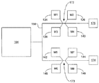
도 2는 본 발명의 실시예들과 관련하여 사용될 수 있는 대표적인 네트워크 시스템 구성을 예시한다.
도 3은 PCB의 일면 상에 장착된 컴포넌트들을 갖는 전원 공급 장치의 대표적인 실시예의 측면도를 예시한다.
도 4는 PCB의 양면 상에 장착되는 능동 컴포넌트들을 갖는 소형화된 전원 공급 장치의 대표적인 실시예의 측면도를 예시한다.
도 5는 본 발명의 대표적인 실시예에 따른 소형화된 전원 공급 장치 내에 사용될 수 있는 차폐된 트레이스(shielded trace)의 측면도를 예시한다.
도 6은 본 발명의 대표적인 실시예에 따른 소형화된 전원 공급 장치를 위한 PCB 레이아웃의 평면도를 예시한다.
도 7은 본 발명의 대표적인 실시예에 따른 소형화된 전원 공급 장치를 제조하기 위한 방법의 순서도를 예시한다.
도 8은 본 발명의 대표적인 실시예에 따른 메모리 시스템 레이아웃의 사시도를 예시한다.
도 9는 본 발명의 대표적인 실시예에 따른 메모리 시스템 및 시스템 데이터 라인들의 평면도를 예시한다.
도 10은 본 발명의 대표적인 실시예에 따른 시스템 클록 라인들의 블록도를 예시한다.
도 11은 본 발명의 대표적인 실시예에 따른 메모리 시스템 레이아웃 및 시스템 어드레스 라인의 평면도를 예시한다.
도 12는 본 발명의 대표적인 실시예에 따른 메모리 성능을 최적화하기 위한 방법의 블록도를 예시한다.
도 13은 본 발명의 대표적인 실시예에 따른 볼 그리드 어레이 어댑터에 대한 핀 그리드 어레이의 개략적인 평면도를 예시한다.
도 14는 본 발명의 대표적인 실시예에 따른 볼 그리드 어레이 어댑터에 대한 핀 그리드 어레이의 개략적인 측면도를 예시한다.
도 15는 본 발명의 대표적인 실시예에 따른 케이싱 내에 배치된 기계 가공된 핀 소켓의 단면도를 예시한다.
도 16은 본 발명의 대표적인 실시예에 따른 PCB 상에 배치되는 볼 그리드 어레이 어댑터에 대한 핀 그리드 어레이의 평면도를 예시한다.
도 17은 본 발명의 대표적인 실시예에 따른 대표적인 2색 LED 전기 회로를 예시한다.
도 18은 LED 회로의 일부 실시예들에 대한 PCB 레이아웃의 대표적인 실시예의 개략도를 예시한다.For the manner in which the above cited and other features and advantages of the present invention are obtained, a more detailed description of the invention will be made based on the specific embodiments thereof, which are illustrated in the accompanying drawings. Given that the drawings show only typical embodiments of the invention and are therefore not to be considered limiting of its scope, the invention will be described and interpreted as additional specificity and detail through the use of the accompanying drawings in which:
1 illustrates an exemplary system that provides a suitable operating environment for use of the present invention.
2 illustrates an exemplary network system configuration that may be used in connection with embodiments of the present invention.
3 illustrates a side view of a representative embodiment of a power supply having components mounted on one side of a PCB.
4 illustrates a side view of a representative embodiment of a miniaturized power supply having active components mounted on both sides of a PCB.
5 illustrates a side view of a shielded trace that may be used in a miniaturized power supply in accordance with a representative embodiment of the present invention.
6 illustrates a top view of a PCB layout for a miniaturized power supply in accordance with an exemplary embodiment of the present invention.
7 illustrates a flowchart of a method for manufacturing a miniaturized power supply according to an exemplary embodiment of the present invention.
8 illustrates a perspective view of a memory system layout in accordance with an exemplary embodiment of the present invention.
9 illustrates a top view of a memory system and system data lines in accordance with an exemplary embodiment of the present invention.
10 illustrates a block diagram of system clock lines in accordance with an exemplary embodiment of the present invention.
11 illustrates a top view of a memory system layout and a system address line in accordance with an exemplary embodiment of the present invention.
12 illustrates a block diagram of a method for optimizing memory performance in accordance with an exemplary embodiment of the present invention.
13 illustrates a schematic top view of a pin grid array for a ball grid array adapter in accordance with an exemplary embodiment of the present invention.
14 illustrates a schematic side view of a pin grid array for a ball grid array adapter in accordance with an exemplary embodiment of the present invention.
15 illustrates a cross-sectional view of a machined pin socket disposed in a casing in accordance with an exemplary embodiment of the present invention.
16 illustrates a top view of a pin grid array for a ball grid array adapter disposed on a PCB in accordance with an exemplary embodiment of the present invention.
17 illustrates an exemplary two-color LED electrical circuit in accordance with an exemplary embodiment of the present invention.
18 illustrates a schematic diagram of a representative embodiment of a PCB layout for some embodiments of an LED circuit.
본 발명은 전자 시스템들 및 컴포넌트들에 관한 것이다. 특히, 본 발명은 소형화 기법들, 시스템들, 및 전원 공급 장치들, 메모리, 인터커넥션들, 및 LED들에 관련된 장치에 관한 것이다.The present invention relates to electronic systems and components. In particular, the present invention relates to miniaturization techniques, systems, and apparatus related to power supplies, memory, interconnects, and LEDs.
본 개시 및 청구항들에서, 어레이라는 용어는 복수의 인접한 행들 및 복수의 인접한 열들을 포함하는 임의의 적절한 배열을 지칭할 수 있다.In the present disclosure and claims, the term array may refer to any suitable arrangement including a plurality of adjacent rows and a plurality of adjacent columns.
본 발명의 다음의 개시는 5개의 부제들, 즉 "대표적인 동작 환경," "전원 공급 장치들," "메모리," "IC 커넥터들," 및 "로직 칩/LED 연결"로 분류된다. 부제들의 사용은 독자의 편의만을 위한 것이며 임의의 의미로 제한하는 것으로서 해석되어서는 안 된다.The following disclosure of the present invention is classified into five subtitles, "typical operating environment," "power supplies," "memory," "IC connectors," and "logic chip / LED connection." The use of subtitles is for the convenience of the reader only and should not be construed as limiting in any sense.
대표적인 동작 환경Representative operating environment
도 1 및 대응하는 논의는 본 발명의 실시예들에 따른 적절한 동작 환경의 일반적인 설명을 제공하도록 의도된다. 이하 더 논의되는 바와 같이, 본 발명의 실시예들은 이하에 논의되는 바와 같이, 네트워크화된 또는 조합 구성을 포함하는 다양한 커스터마이즈가능 엔터프라이즈 구성들에서 하나 이상의 동적 모듈식(modular) 프로세싱 유닛들의 사용을 포함한다.1 and corresponding discussion are intended to provide a general description of a suitable operating environment in accordance with embodiments of the present invention. As discussed further below, embodiments of the present invention include the use of one or more dynamic modular processing units in various customizable enterprise configurations, including networked or combinational configurations, as discussed below. .
본 발명의 실시예들은 하나 이상의 컴퓨터 판독가능 매체를 포함하며, 여기서 각 매체는 데이터를 조작하기 위한 데이터 또는 컴퓨터 실행가능 명령어들을 그 위에 포함하거나 포괄하도록 구성될 수 있다. 컴퓨터 실행가능 명령어들은 각종 상이한 기능들을 수행할 수 있는 범용 모듈식 프로세싱 유닛과 관련된 것 또는 제한된 수의 기능들을 수행할 수 있는 특수 용도 모듈식 프로세싱 유닛과 관련된 것과 같은 하나 이상의 프로세서들에 의해 액세스될 수 있는 데이터 구조들, 객체들, 프로그램들, 루틴들, 또는 다른 프로그램 모듈들을 포함한다.Embodiments of the invention include one or more computer readable media, where each medium may be configured to include or encompass data or computer executable instructions for manipulating data. The computer executable instructions may be accessed by one or more processors such as those associated with a general purpose modular processing unit capable of performing a variety of different functions or associated with a special purpose modular processing unit capable of performing a limited number of functions. Data structures, objects, programs, routines, or other program modules.
컴퓨터 실행가능 명령어들은 엔터프라이즈의 하나 이상의 프로세서들로 하여금 특정 기능 또는 기능들의 그룹을 수행하게 하고 처리 방법들에 대한 단계들을 구현하기 위한 프로그램 코드 수단의 예들이다. 더욱이, 실행가능 명령어들의 특정 시퀀스는 그러한 단계들을 구현하는데 사용될 수 있는 대응하는 액트(act)들의 일례를 제공한다.Computer executable instructions are examples of program code means for causing one or more processors in an enterprise to perform a particular function or group of functions and to implement steps for processing methods. Moreover, the particular sequence of executable instructions provides one example of corresponding acts that can be used to implement such steps.
컴퓨터 판독가능 매체의 예들은 랜덤 액세스 메모리("RAM"), 읽기 전용 메모리("ROM"), 프로그램가능 읽기 전용 메모리("PROM"), 소거가능 프로그램가능 읽기 전용 메모리("EPROM"), 전기적 소거가능 프로그램가능 읽기 전용 메모리("EEPROM"), 콤팩트 디스크 읽기 전용 메모리("CD-ROM"), 임의의 반도체 저장 디바이스(예를 들어, 플래시 메모리, 스마트 미디어 등), 또는 프로세싱 유닛에 의해 액세스될 수 있는 데이터 또는 실행가능 명령어들을 제공할 수 있는 임의의 다른 디바이스 또는 컴포넌트를 포함한다.Examples of computer readable media include random access memory ("RAM"), read-only memory ("ROM"), programmable read-only memory ("PROM"), erasable programmable read-only memory ("EPROM"), electrical Access by erasable programmable read-only memory ("EEPROM"), compact disk read-only memory ("CD-ROM"), any semiconductor storage device (eg, flash memory, smart media, etc.), or by a processing unit Any other device or component capable of providing data or executable instructions that may be.
도 1을 참조하면, 대표적인 엔터프라이즈는 범용 또는 특수 용도 프로세싱 유닛으로서 사용될 수 있는 모듈식 프로세싱 유닛(10)을 포함한다. 예를 들어, 모듈식 프로세싱 유닛(10)은 단독으로 또는 개인용 컴퓨터, 노트북 컴퓨터, 개인 휴대 정보 단말기("PDA") 또는 다른 핸드헬드 디바이스, 워크스테이션, 미니컴퓨터, 메인프레임, 슈퍼컴퓨터, 멀티프로세서 시스템, 네트워크 컴퓨터, 프로세서 기반 소비자 디바이스, 스마트 가전 또는 디바이스, 제어 시스템 등으로서 하나 이상의 유사한 모듈식 프로세싱 유닛들과 함께 사용될 수 있다. 다수의 프로세싱 유닛들을 동일한 엔터프라이즈에서 사용하는 것은 증가된 처리 성능들을 제공한다. 예를 들어, 엔터프라이즈의 각 프로세싱 유닛은 특정 태스크에 전용될 수 있거나 분산 처리에 공동으로 관여할 수 있다.Referring to FIG. 1, a representative enterprise includes a
도 1에서, 모듈식 프로세싱 유닛(10)은 그의 다양한 컴포넌트들을 연결하도록 구성되고, 데이터가 2개 이상의 컴포넌트들 사이에서 교환될 수 있게 하는 하나 이상의 버스들 및/또는 인터커넥트(들)(12)를 포함한다. 버스(들)/인터커넥트(들)(12)는 다양한 버스 아키텍처들 중 어느 하나를 사용하는 메모리 버스, 주변 버스, 또는 로컬 버스를 포함하는 다양한 버스 구조들 중 하나를 포함할 수 있다. 버스(들)/인터커넥트(들)(12)에 의해 연결된 전형적인 컴포넌트들은 하나 이상의 프로세서들(14) 및 하나 이상의 메모리들(16)을 포함한다. 다른 컴포넌트들은 이하 "데이터 조작 시스템(들)(data manipulating system(s))(18)"으로서 지칭되는 로직, 하나 이상의 시스템들, 하나 이상의 서브시스템들 및/또는 하나 이상의 I/O 인터페이스들의 사용을 통해서 버스(들)/인터커넥트(들)(12)에 선택적으로 연결될 수 있다. 더욱이, 다른 컴포넌트들은 로직, 하나 이상의 시스템들, 하나 이상의 서브시스템들 및/또는 하나 이상의 I/O 인터페이스들의 사용을 통해서 버스(들)/인터커넥트(들)(12)에 외부적으로 연결될 수 있으며, 및/또는 모듈식 프로세싱 유닛(들)(30) 및/또는 전용 디바이스(들)(34)와 같은 로직, 하나 이상의 시스템들, 하나 이상의 서브시스템들 및/또는 하나 이상의 I/O 인터페이스들로서 기능할 수 있다. I/O 인터페이스들의 예들은 하나 이상의 대용량 저장 디바이스 인터페이스들, 하나 이상의 입력 인터페이스들, 하나 이상의 출력 인터페이스들 등을 포함한다. 따라서, 본 발명의 실시예들은 하나 이상의 I/O 인터페이스들을 사용하는 능력 및/또는 사용된 로직 또는 다른 데이터 조작 시스템에 기초하여 제품의 유용성을 변경하는 능력을 포함한다.In FIG. 1, the
로직은 인터페이스, 시스템의 일부, 서브시스템에 결합될 수 있으며 및/또는 특정 태스크를 수행하는데 사용될 수 있다. 따라서, 로직 또는 다른 데이터 조작 시스템은 예를 들어 IEEE 1394(파이어와이어(firewire))를 가능하게 할 수 있으며, 여기서 로직 또는 다른 데이터 조작 시스템은 I/O 인터페이스이다. 대안적으로 또는 추가적으로, 모듈식 프로세싱 유닛이 다른 외부 시스템 또는 서브시스템에 결합되는 것을 가능하게 하는 로직 또는 다른 데이터 조작 시스템이 사용될 수 있다. 예를 들어, 외부 시스템 또는 서브시스템은 특수 I/O 연결을 포함하거나 포함하지 않을 수 있다. 대안적으로 또는 추가적으로, 로직 또는 다른 데이터 조작 시스템이 사용될 수 있으며, 여기서 어떤 외부 I/O도 로직과 관련되지 않는다. 본 발명의 실시예들은 또한 차량들의 ECU들, 유압 제어 시스템들 등을 위한 것과 같은 특수 로직 및/또는 특정 하드웨어를 제어하는 방법을 프로세서에 통지하는 로직의 사용을 포함한다. 더욱이, 당업자들은 본 발명의 실시예들이 로직, 시스템들, 서브시스템들 및/또는 I/O 인터페이스들을 사용하는 상이한 시스템들 및/또는 구성들의 과다(plethora)를 포괄하는 것을 인식할 것이다.Logic may be coupled to an interface, part of a system, subsystem, and / or may be used to perform a particular task. Thus, logic or other data manipulation systems may enable, for example, IEEE 1394 (firewire), where the logic or other data manipulation system is an I / O interface. Alternatively or additionally, logic or other data manipulation systems may be used that allow the modular processing unit to be coupled to other external systems or subsystems. For example, an external system or subsystem may or may not include special I / O connections. Alternatively or additionally, logic or other data manipulation systems may be used, where no external I / O is associated with the logic. Embodiments of the present invention also include the use of logic to notify the processor of special logic and / or methods of controlling specific hardware, such as for ECUs, hydraulic control systems, etc. of vehicles. Moreover, those skilled in the art will recognize that embodiments of the present invention encompass a plethora of different systems and / or configurations using logic, systems, subsystems and / or I / O interfaces.
앞서 제공된 바와 같이, 본 발명의 실시예들은 하나 이상의 I/O 인터페이스들을 사용하는 능력 및/또는 사용된 로직 또는 다른 데이터 조작 시스템에 기초하여 제품의 유용성을 변경하는 능력을 포괄한다. 예를 들어, 모듈식 프로세싱 유닛은 데스크톱 컴퓨터로서의 사용을 위해 설계된 하나 이상의 I/O 인터페이스들 및 로직을 포함하는 개인용 컴퓨팅 시스템의 일부일지라도, 로직 또는 다른 데이터 조작 시스템은 2개의 표준 RCA들을 통해서 아날로그 오디오를 취하여 그들을 IP 어드레스에 브로드캐스팅하기를 원하는 뮤직 스테이션을 위한 오디오 인코딩을 수행하기 위해 플래시 메모리 또는 로직을 포함하는 것으로 변경될 수 있다. 따라서, 모듈식 프로세싱 유닛은 모듈식 프로세싱 유닛의 백 플레인(back plane) 상에서 데이터 조작 시스템(들)(예를 들어, 로직, 시스템, 서브시스템, I/O 인터페이스(들) 등)에 이루어진 수정으로 인해 컴퓨터 시스템이라기보다는 오히려 기구로서 사용되는 시스템의 일부일 수 있다. 따라서, 백 플레인 상에서 데이터 조작 시스템(들)의 수정은 모듈식 프로세싱 유닛의 적용을 변경할 수 있다. 따라서, 본 발명의 실시예들은 충분히 적응가능한 모듈식 프로세싱 유닛들을 포괄한다.As provided above, embodiments of the present invention encompass the ability to use one or more I / O interfaces and / or the ability to alter the usefulness of a product based on the logic or other data manipulation system used. For example, even though the modular processing unit is part of a personal computing system that includes one or more I / O interfaces and logic designed for use as a desktop computer, the logic or other data manipulation system may be analog audio through two standard RCAs. Can be changed to include flash memory or logic to perform audio encoding for a music station that wants to take and broadcast them to an IP address. Thus, the modular processing unit is a modification made to the data manipulation system (s) (eg, logic, system, subsystem, I / O interface (s), etc.) on the back plane of the modular processing unit. This may be part of a system used as an instrument rather than a computer system. Thus, modification of the data manipulation system (s) on the backplane may change the application of the modular processing unit. Accordingly, embodiments of the present invention encompass modular processing units that are sufficiently adaptable.
앞서 제공된 바와 같이, 프로세싱 유닛(10)은 중앙 프로세서(또는 CPU)와 같은 하나 이상의 프로세서들(14) 및 선택적으로 특정 기능 또는 태스크를 수행하도록 설계된 하나 이상의 다른 프로세서들을 포함한다. 그것은 전형적으로 메모리(들)(16), 자기 하드 디스크, 제거가능 자기 디스크, 자기 카세트, 광 디스크와 같은 컴퓨터 판독가능 매체 상에 제공되는 또는 컴퓨터 판독가능 매체로 간주될 수 있는 통신 연결로부터 제공되는 명령어들을 실행하는 프로세서(14)이다.As provided above, processing
메모리(들)(16)는 데이터를 조작하기 위한 데이터 또는 명령어들을 그 위에 포함하거나 포괄하도록 구성될 수 있고, 버스(들)/인터커넥트(들)(12)를 통해서 프로세서(들)(14)에 의해 액세스될 수 있는 하나 이상의 컴퓨터 판독가능 매체를 포함한다. 메모리(들)(16)는 예를 들어 정보를 영속적으로 저장하는데 사용되는 ROM(들)(20), 및/또는 정보를 일시적으로 저장하는데 사용되는 RAM(들)(22)을 포함할 수 있다. ROM(들)(20)은 예컨대 모듈식 프로세싱 유닛(10)의 시동 동안 통신을 수립하는데 사용되는 하나 이상의 루틴들을 갖는 기본 입력/출력 시스템("BIOS")을 포함할 수 있다. 동작 동안, RAM(들)(22)은 하나 이상의 프로그램 모듈들, 예컨대 하나 이상의 운영 체제들, 애플리케이션 프로그램들, 및/또는 프로그램 데이터를 포함할 수 있다.The memory (s) 16 may be configured to include or encompass data or instructions thereon for manipulating data, and to the processor (s) 14 via the bus (s) / interconnect (s) 12. And one or more computer readable media that can be accessed by. Memory (s) 16 may include, for example, ROM (s) 20 used to permanently store information, and / or RAM (s) 22 used to temporarily store information. . ROM (s) 20 may comprise a basic input / output system (“BIOS”) having one or more routines used to establish communication, for example, during startup of
예시된 바와 같이, 본 발명의 적어도 일부 실시예들은 각종 상이한 애플리케이션들에서 유닛의 사용을 가능하게 하는 보다 견고한 프로세싱 유닛을 제공하는 비주변 인케이스먼트(non-peripheral encasement)를 포괄한다. 도 1에서, 하나 이상의 대용량 저장 디바이스 인터페이스들(데이터 조작 시스템(들)(18)으로서 예시됨)은 하나 이상의 대용량 저장 디바이스들(24)을 버스(들)/인터커넥트(들)(12)에 연결하는데 사용될 수 있다. 대용량 저장 디바이스들(24)은 모듈식 프로세싱 유닛(10) 주변에 있고 모듈식 프로세싱 유닛(10)이 대량의 데이터를 유지하는 것을 가능하게 한다. 대용량 저장 디바이스들의 예들은 하드 디스크 드라이브들, 자기 디스크 드라이브들, 테이프 드라이브들 및 광 디스크 드라이브들을 포함한다.As illustrated, at least some embodiments of the invention encompass non-peripheral encasements that provide a more robust processing unit that enables the use of the unit in a variety of different applications. In FIG. 1, one or more mass storage device interfaces (illustrated as data manipulation system (s) 18) connect one or more mass storage devices 24 to the bus (s) / interconnect (s) 12. It can be used to Mass storage devices 24 are around the
대용량 저장 디바이스(24)는 자기 하드 디스크, 제거가능 자기 디스크, 자기 카세트, 광 디스크, 또는 다른 컴퓨터 판독가능 매체로부터 판독되며 및/또는 이들에 기록될 수 있다. 대용량 저장 디바이스들(24) 및 그들의 대응하는 컴퓨터 판독가능 매체는 하나 이상의 프로그램 모듈들, 예컨대 운영 체제, 하나 이상의 애플리케이션 프로그램들, 다른 프로그램 모듈들, 또는 프로그램 데이터를 포함할 수 있는 데이터 및/또는 실행가능 명령어들의 비휘발성 스토리지를 제공한다. 그러한 실행가능 명령어들은 본 출원에 개시된 방법들에 대한 단계들을 구현하기 위한 프로그램 코드 수단의 예들이다.Mass storage device 24 may be read from and / or written to a magnetic hard disk, removable magnetic disk, magnetic cassette, optical disk, or other computer readable medium. Mass storage devices 24 and their corresponding computer readable media may comprise one or more program modules, such as an operating system, one or more application programs, other program modules, or data and / or executable data. Provides nonvolatile storage of possible instructions. Such executable instructions are examples of program code means for implementing the steps for the methods disclosed herein.
데이터 조작 시스템(들)(18)은 데이터 및/또는 명령어들이 하나 이상의 대응하는 주변 I/O 디바이스들(26)을 통해서 모듈식 프로세싱 유닛(10)과 교환될 수 있게 하는데 사용될 수 있다. 주변 I/O 디바이스들(26)의 예들은 키보드와 같은 입력 디바이스들 및/또는 마우스, 트랙볼, 라이트 펜, 스타일러스, 또는 다른 포인팅 디바이스, 마이크로폰, 조이스틱, 게임 패드, 위성 방송 수신 안테나, 스캐너, 캠코더, 디지털 카메라, 센서 등과 같은 대체 입력 디바이스들, 및/또는 모니터 또는 표시 화면, 스피커, 프린터, 제어 시스템 등과 같은 출력 디바이스들을 포함한다. 유사하게, 주변 I/O 디바이스들(26)을 버스(들)/인터커넥트(들)(12)에 연결하는데 사용될 수 있는 특수 로직과 결합되는 데이터 조작 시스템(들)(18)의 예들은 직렬 포트, 병렬 포트, 게임 포트, 범용 직렬 버스("USB"), 파이어와이어(IEEE 1394), 무선 수신기, 비디오 어댑터, 오디오 어댑터, 병렬 포트, 무선 송신기, 임의의 병렬 또는 직렬화 I/O 주변 장치들 또는 다른 인터페이스를 포함한다.Data manipulation system (s) 18 may be used to enable data and / or instructions to be exchanged with the
데이터 조작 시스템(들)(18)은 하나 이상의 네트워크 인터페이스들(28)을 통해서 정보의 교환을 가능하게 한다. 네트워크 인터페이스들(28)의 예들은 정보가 프로세싱 유닛들 사이에서 교환될 수 있게 하는 연결, 근거리 통신망("LAN") 또는 모뎀에 연결을 위한 네트워크 어댑터, 무선 링크, 또는 인터넷과 같은 광역 통신망("WAN")에 연결을 위한 다른 어댑터를 포함한다. 네트워크 인터페이스(28)는 모듈식 프로세싱 유닛(10)과 통합되거나 이 유닛 주변에 있을 수 있고, LAN, 무선 네트워크, WAN 및/또는 프로세싱 유닛들 사이의 임의의 연결과 결합될 수 있다.Data manipulation system (s) 18 enable the exchange of information via one or more network interfaces 28. Examples of network interfaces 28 include a wide area network such as a connection that allows information to be exchanged between processing units, a local area network ("LAN") or a network adapter for connecting to a modem, a wireless link, or the Internet (""). WAN ") and other adapters for connection to the WAN. The network interface 28 may be integrated with or surrounding the
데이터 조작 시스템(들)(18)은 모듈식 프로세싱 유닛(10)이 정보를 하나 이상의 다른 로컬 또는 리모트 모듈식 프로세싱 유닛들(30) 또는 컴퓨터 디바이스들과 교환할 수 있게 한다. 모듈식 프로세싱 유닛(10)과 모듈식 프로세싱 유닛(30) 사이의 연결은 하드와이어드(hardwired) 및/또는 무선 링크들을 포함할 수 있다. 따라서, 본 발명의 실시예들은 직접적인 버스-대-버스(bus-to-bus) 연결들을 포함한다. 이것은 대형 버스 시스템의 제작을 가능하게 한다. 그것은 또한 엔터프라이즈의 직접적인 버스-대-버스 연결들로 인해 현재 공지되어 있는 해킹을 제거한다. 더욱이, 데이터 조작 시스템(들)(18)은 모듈식 프로세싱 유닛(10)이 정보를 하나 이상의 전용 I/O 연결들(32) 및/또는 하나 이상의 전용 디바이스들(34)과 교환할 수 있게 한다.The data manipulation system (s) 18 allow the
프로세싱 유닛에 액세스가능한 프로그램 모듈들 또는 그의 일부들은 리모트 메모리 저장 디바이스에 저장될 수 있다. 더욱이, 네트워크화된 시스템 또는 조합된 구성에서, 모듈식 프로세싱 유닛(10)은 기능들 또는 태스크들이 복수의 프로세싱 유닛들에 의해 수행되는 분산 컴퓨팅 환경에 관여할 수 있다. 대안적으로, 조합된 구성/엔터프라이즈의 각 프로세싱 유닛은 특정 태스크에 전용될 수 있다. 따라서, 예를 들어, 엔터프라이즈의 하나의 프로세싱 유닛은 비디오 데이터에 전용될 수 있음으로써, 종래의 비디오 카드를 대체하고, 그러한 태스크들을 종래의 기법들을 통해서 수행하기 위한 증가된 처리 능력들을 제공한다.Program modules or portions thereof accessible to the processing unit may be stored in the remote memory storage device. Moreover, in a networked system or combined configuration, the
당업자들은 본 발명이 많은 유형들의 컴퓨터 시스템 구성을 갖는 네트워크화된 컴퓨터 환경들 내에서 실시될 수 있다는 것을 이해하겠지만, 도 2는 네트워크를 통해 서버에 연결된 클라이언트들을 포함하는 네트워크 환경 내에서 본 발명의 실시예를 대표한다. 도 2는 네트워크에 연결된 2개의 클라이언트들을 포함하는 실시예를 예시하지만, 대안적인 실시예들은 네트워크에 연결된 하나의 클라이언트 또는 네트워크에 연결된 많은 클라이언트들을 포함한다. 더욱이, 본 발명에 따른 실시예들도 세계 전체에 걸쳐 네트워크에 연결된 다수의 클라이언트들을 포함하며, 여기서 네트워크는 인터넷과 같은 광역 네트워크이다.Those skilled in the art will understand that the present invention may be practiced in networked computer environments having many types of computer system configurations, but FIG. 2 illustrates an embodiment of the present invention in a network environment including clients connected to a server via a network. Represents. Although FIG. 2 illustrates an embodiment comprising two clients connected to a network, alternative embodiments include one client connected to a network or many clients connected to a network. Moreover, embodiments according to the present invention also include multiple clients connected to a network throughout the world, where the network is a wide area network such as the Internet.
전원 공급 장치들Power supplies
본 발명의 일부 양태들은 전원 공급 장치들에 관한 것이다. 상기 소개된 바와 같이, 많은 통상적인 전원 공급 장치 설계들은 통상 매우 공간 효율적이지 않다. 전원 공급 장치는 능동 컴포넌트들 및 수동 컴포넌트들을 포함할 수 있는 복수의 전자 컴포넌트들을 포함할 수 있다. 능동 컴포넌트들은 스위치들(예를 들어, 양극성 트랜지스터들, 전계 효과 트랜지스터들 등), 조정기(regulator)들, 비교기(comparator)들 등과 같은 부품들을 포함한다. 수동 컴포넌트들은 저항기들, 인덕터들, 커패시터들 등과 같은 부품들을 포함한다. 전자 컴포넌트들은 전형적으로 PCB 상에 장착되고 PCB 상의 트레이스들을 통해 인터커넥트된다. 전형적으로, 전자 컴포넌트들은 PCB의 일면 상에만 장착된다. 이는 비용을 고려하여 전자 산업에서 바람직하게 간주된다. 일부 경우들에서, 수동 컴포넌트들(예를 들어, 작은 커패시터들 또는 작은 저항기들)은 보드의 대향면 상에 때때로 위치된다. 예를 들어, 도 3은 50으로 전체적으로 도시된 전원 공급 장치를 예시하고, 여기서 PCB(52)는 PCB(또는 다른 회로 기판)의 일면(58) 상에 장착된 복수의 컴포넌트들(54 및 56)을 갖는다. 컴포넌트들은 능동 컴포넌트들(54) 및 수동 컴포넌트들(56)을 포함할 수 있다. 컴포넌트들 사이의 인터커넥션들은 트레이스들(60)(예를 들어, 비전도성 기판에 부착되거나 증착된 전도성 재료)에 의해 제공된다. PCB는 예를 들어, 트레이스들(미도시)의 다수의 층들을 제공하는 다층 PCB일 수 있다.Some aspects of the invention relate to power supplies. As introduced above, many conventional power supply designs are typically not very space efficient. The power supply may include a plurality of electronic components, which may include active components and passive components. Active components include components such as switches (eg, bipolar transistors, field effect transistors, etc.), regulators, comparators, and the like. Passive components include components such as resistors, inductors, capacitors, and the like. Electronic components are typically mounted on a PCB and interconnected through traces on the PCB. Typically, electronic components are mounted only on one side of the PCB. This is considered desirable in the electronics industry in view of cost. In some cases, passive components (eg, small capacitors or small resistors) are sometimes located on the opposite side of the board. For example, FIG. 3 illustrates a power supply shown generally at 50, where PCB 52 is a plurality of
본 발명의 일부 실시예들에 따른 소형화된 전원 공급 장치가 도 4에 도시된다. 통상적인 전원 공급 장치와 대조적으로, 소형화된 전원 공급 장치(70)는 PCB(72)의 양면 상에 위치된 능동 컴포넌트들(54)을 포함할 수 있다. 따라서, 일부 능동 컴포넌트들은 일부 실시예들에 있어서 서로 직접적으로 대향되어 위치될 수 있다. 다른 실시예들에 있어서, 능동 컴포넌트들은 서로 대향되고 부분적으로 오버랩될 수 있다. 수동 컴포넌트들(56)도 PCB의 일면 또는 양면들 상에 위치될 수 있다. 트레이스들(60) 및 비아들(80)는 컴포넌트들을 인터커넥트할 수 있다.A miniaturized power supply in accordance with some embodiments of the present invention is shown in FIG. 4. In contrast to conventional power supplies,
몇몇 이점들이 PCB(72)의 양면들 상에 컴포넌트들을 장착함으로써 획득될 수 있다. 예를 들어, 컴포넌트들 사이의 인터커넥션 거리들이 감소될 수 있다. 예를 들어, 제 1 컴포넌트(54a) 및 제 2 컴포넌트(54b)를 고려하면, 이들 컴포넌트들은 PCB의 동일면 상에 있을 때, 도 3에 도시된 것보다 실질적으로 보다 가깝게 위치될 수 없다. 예를 들어, 일부 공간이 컴포넌트 사이즈 허용 공차들 및 머신의 픽 앤 플레이스(pick and place)를 위한 접근을 가능하게 하기 위하여 컴포넌트들 사이에서 전형적으로 요구된다. 따라서, 제 2 컴포넌트의 단자에 제 1 컴포넌트의 단자를 인터커넥트하는 트레이스(60a)는 컴포넌트들의 수평 치수 이상의 길이를 일반적으로 가져야 한다. 예를 들어, 약 0.64 센티미터들(약 0.25 인치들)의 수평 길이들을 갖는 2개의 컴포넌트들을 인터커넥트하기 위해, 트레이스는 길이가 적어도 약 0.64 센티미터들(약 0.25 인치들)이어야 한다.Some advantages can be obtained by mounting components on both sides of the
대조적으로, 컴포넌트들(54a, 54b)이 PCB(72)의 대향면 상에 서로 대향되어 위치될 때, 트레이스 길이는 상당히 짧을 수 있다. 예를 들어, 단자들이 서로 직접적으로 대향되도록 컴포넌트들이 위치될 수 있고, 이는 트레이스 길이를 기본적으로 컴포넌트들을 서로 인터커넥트하는 비아(80a)의 길이로 만든다(예를 들어, 패드(pad)로 인한 부가적인 길이가 존재할 수 있음). 따라서, 약 0.13 센티미터들(약 0.05 인치들)의 두께를 갖는 PCB(72)에 대해, 트레이스 길이는 길이가 약 0.13 센티미터들(약 0.05 인치들)이다-약 5배율의 감소.In contrast, when the
본 발명의 일부 실시예들에 제공된 트레이스 길이의 감소는 다수의 이점들을 제공할 수 있다. 예를 들어, 이상적인 전기적 인터커넥션은 제로 저항, 제로 커패시턴스, 및 제로 인덕턴스를 갖지만, 실제 트레이스들은 일부 기생 저항, 커패시턴스, 및 인덕턴스(RLC)를 나타낸다. 트레이스의 기생 RLC는 다양한 파라미터들(예를 들어, 보드 두께, 전도성 재료 두께, 절연 기판의 유전 상수, 다른 트레이스들의 근접성 등)의 함수이지만, 트레이스의 길이 상에 기생 RLC의 현저한 종속성이 존재한다. 일반적으로, 기생 RLC는 트레이스의 길이와 함께 선형적으로 증가한다. 따라서, 트레이스 길이를 감소시킴으로써, 기생 RLC는 감소될 수 있고, 그것은 결과적으로 전기적 연결들이 이상적인(예를 들어, 제로 RLC) 인터커넥션들과 보다 유사하게 작동하게 한다. 일부 경우들에서, 감소된 기생 RLC는 컴포넌트 값들의 조정을 요구할 수 있다. 예를 들어, 회로 설계는 어떤 양의 인덕턴스를 요구할 수 있다. 일면(one-sided) 설계에서, 이러한 요구된 인덕턴스는 컴포넌트에 의해 부품 내에 및 PCB(52)의 기생 인덕턴스에 의해 부품 내에 제공될 수 있다. 양면(two-sided) 설계에서, 감소된 기생 인덕턴스가 PCB(72)에 의해 제공되고, 따라서 컴포넌트 인덕턴스는 감소될 수 있다. 다른 예로서, 일면 설계에서, 컴포넌트 값은 기생 RLC를 보상하도록 요구될 수 있으며, 따라서 감소된 기생 RLC로 인해 양면 설계에서 컴포넌트 값이 감소될 수 있거나 컴포넌트가 전체적으로 제거될 수 있다.The reduction in trace length provided in some embodiments of the present invention can provide a number of advantages. For example, an ideal electrical interconnect has zero resistance, zero capacitance, and zero inductance, but the actual traces exhibit some parasitic resistance, capacitance, and inductance (RLC). The parasitic RLC of the trace is a function of various parameters (eg, board thickness, conductive material thickness, dielectric constant of the insulating substrate, proximity of other traces, etc.), but there is a significant dependency of the parasitic RLC on the length of the trace. In general, parasitic RLC increases linearly with the length of the trace. Thus, by reducing the trace length, the parasitic RLC can be reduced, which in turn allows the electrical connections to work more like ideal (eg zero RLC) interconnections. In some cases, reduced parasitic RLC may require adjustment of component values. For example, circuit design may require some amount of inductance. In a one-sided design, this required inductance can be provided in the part by the component and in the part by the parasitic inductance of the PCB 52. In a two-sided design, reduced parasitic inductance is provided by the
감소된 트레이스 길이의 다른 이점은 감소된 노이즈 방출 및 감소된 노이즈 민감성이다. 전기적 인터커넥션은 방사성(radiated) 및 비방사성(non-radiated) 전자기 커플링(electromagnetic coupling)을 통해 모두 노이즈를 방출할 수 있다. 일반적으로, 노이즈 커플링(noise coupling)의 양은 보다 긴 전기적 인터커넥션들에 대해 증가된다. 예를 들어, 보다 긴 트레이스들은 전자기장들을 통해 보다 높은 커플링을 제공하여 서로 사이에서 보다 높은 상호 커패시턴스 또는 인덕턴스를 가질 수 있다. 보다 긴 트레이스들도 전파하는 전자기 파들을 통해 인접한 트레이스들로부터 에너지를 방출하거나 모으는 안테나로서 보다 효과적으로 작용할 수 있다. 따라서, 트레이스 길이를 감소시킴으로써, 노이즈 커플링은 감소될 수도 있다.Other advantages of reduced trace lengths are reduced noise emission and reduced noise sensitivity. Electrical interconnection can emit noise through both radiated and non-radiated electromagnetic coupling. In general, the amount of noise coupling is increased for longer electrical interconnections. For example, longer traces may provide higher coupling through the electromagnetic fields to have higher mutual capacitance or inductance between each other. Longer traces may also act more effectively as an antenna that radiates or collects energy from adjacent traces through propagating electromagnetic waves. Thus, by reducing the trace length, noise coupling may be reduced.
일부 경우들에서, 양면 설계의 트레이스 길이들은 충분히 짧아서, 그렇지 않다면 요구될 수 있는 차폐(shielding)가 제거될 수 있다. 다른 경우들에서, 차폐로 인해 상실된 영역은 현저하게 감소될 수 있다. 예를 들어, 도 5는 PCB(72)의 대향면 상에 장착된 2개의 컴포넌트들(54) 사이에 차폐된 연결을 예시한다. 차폐된 연결은 2개의 컴포넌트들을 전기적으로 연결하고 복수의 차폐 구조들(84)에 의해 둘러싸이는 신호 컨덕터(signal conductor)(82)를 포함한다. 차폐 구조들은 그라운드 플레인(ground plane)에 연결된 비아들 및/또는 트레이스들을 포함할 수 있다. 차폐 구조들이 컴포넌트들의 풋프린트 내부에 완전히 수용됨으로써, 컴포넌트들에 의해 이미 커버된 임의의 부가적인 PCB 영역을 필요로 하지 않는다는 것이 이해될 것이다. 차폐된 연결들은 노이즈를 픽업(pick up)함에 특히 민감한 전기 연결들 및 특히 노이즈를 방출하기 쉬운 전기적 연결들을 위해 사용될 수 있다. 도 5에 도시된 차폐된 연결은 수직 방향으로 존재하지만(신호 컨덕터 및 차폐 구조들을 위한 비아들을 사용함), 차폐된 연결들이 수평 방향으로(신호 컨덕터 및 차폐 구조들을 위한 트레이스를 사용함), 또는 모든 조합을 사용하여 제공될 수 있다.In some cases, the trace lengths of the two-sided design are short enough so that shielding that would otherwise be required can be eliminated. In other cases, the area lost due to shielding can be significantly reduced. For example, FIG. 5 illustrates a shielded connection between two
단축된 트레이스 길이들의 이점은 트레이스들에 의해 소비되는 보드 영역의 양이 감소된다는 점이다. 이러한 영역은 다양한 유익한 방식들로 사용될 수 있다. 예를 들어, 트레이스 폭들이 증가될 수 있다. 일반적으로, 보다 넓은 트레이스 폭들이 결과적으로 보다 높은 전류 취급 성능을 제공하는 보다 낮은 저항 및 인덕턴스를 제공할 수 있다.The advantage of shortened trace lengths is that the amount of board area consumed by the traces is reduced. This area can be used in various beneficial ways. For example, trace widths can be increased. In general, wider trace widths may result in lower resistance and inductance resulting in higher current handling performance.
전원 공급 장치는 또한 인터커넥션 플레인(interconnection plane)들을 효과적으로 사용할 수 있다. 예를 들어, 인터커넥션 플레인은 PCB(72)의 외부 또는 내부 층 상에 배치된 전도성 재료의 필수적으로 연속적인 플레인(예를 들어, 클리어런스 홀(clearance hole)들을 제외한 규정된 2차원 영역 범위 상에서 연속적임)으로 구성될 수 있다. 예를 들어, 그라운드 플레인이 2개 이상의 컴포넌트들의 그라운드 단자들을 함께 연결하기 위해 사용될 수 있다. 다른 예로서, 파워 플레인(power plane)은 2개 이상의 컴포넌트들의 파워 단자들을 함께 연결시키기 위해 사용될 수 있다. 인터커넥션 플레인은 그것이 플레인에 결부된 컴포넌트들 사이에 낮은 저항 및 낮은 인덕턴스 인터커넥션을 제공하기 때문에 유용할 수 있다. 필요할 때, 홀들은 플레인에 전기적으로 연결되지 않고 플레인을 통해 통과하도록 비아들(예를 들어, 신호 인터커넥션들을 위한)을 위해 클리어런스를 제공하도록 플레인 내에 제공될 수 있다.The power supply can also effectively use interconnection planes. For example, the interconnect plane is continuous over a defined two-dimensional area range excluding essentially continuous planes of conductive material (eg, clearance holes) disposed on the outer or inner layers of the
일부 경우에서, 단일 지점에서 서로에 인터커넥트된 하나 이상의 분할된 플레인(slit plane)들을 제공하는 것이 유용할 수 있다. 예를 들어, 도 6은 PCB(92)가 전원 공급 장치 부분(94) 및 동작 회로 부분(96)을 포함하는 전자 시스템을 위한 PCB 레이아웃(90)을 예시한다. 다수 분할된 플레인부들(98, 100, 및 102)이 제공된다. 분할된 플레인들은 예를 들어, 분할된 플레인들을 규정하기 위해 컷 어웨이(cut away)된 또는 에칭된 부분을 갖는 PCB의 외부 또는 내부 상에 배치된 전도성 층일 수 있다. 동작 회로부는 동작 회로부(클리어런스 홀들(104)을 제외함) 아래에 인접한 분할된 플레인부(102)를 포함한다. 전원 공급 장치 부분은 2개의 분할된 플레인부들(98 및 100)을 포함한다. 플레인 부분들은 연결(106)의 단일 지점을 통해 서로에 각각 연결된다. 다수 분할된 플레인들의 사용은 전원 공급 장치 내에 한정되는 전원 공급 장치 내부에 발생된 노이즈를 유지하는 것과 전원 공급 장치의 노이즈 민감 부분들(예를 들어, 플레인(98) 상에 및 하에 배치된)을 전원 공급 장치의 노이즈 발생 부분(예를 들어, 플레인(100)의 상 및 하에 배치된 부분들)으로부터 격리되도록 유지하는 것에 유리할 수 있다.In some cases, it may be useful to provide one or more divided planes interconnected to each other at a single point. For example, FIG. 6 illustrates a
전원 공급 장치의 부가적인 소형화는 커패시터들의 양과 타입을 최적화함으로써 획득될 수 있다. 커패시터들은 전원 공급 장치 내에서 몇몇 용도의 역할을 할 수 있다. 커패시터들은 전원 공급 장치의 사이클들(예를 들어, 선형 공급장치의 교류 입력의 사이클들 또는 스위칭 전원 공급 장치의 스위칭 사이클들 중) 사이에서 전하 저장을 제공할 수 있다. 커패시터들은 서지 전류 요구(surge current demand)들(예를 들어, 그것은 너무 빨리 발생하여 조정기가 반응할 수 없음)을 충족시키기 위해 에너지 저장을 제공할 수도 있다. 커패시터들은 노이즈 필터링(예를 들어, 노이즈 신호들을 그라운드로 션트(shunt)함)을 제공할 수도 있다. 전형적으로, 전원 공급 장치들은 정상(normal) 동작 조건들 하에서의 전하 저장을 위해 요구되는 것을 초과하여 대량의 커패시턴스로서 설계된다. 이러한 과잉 커패시턴스는 캐퍼시터의 효과를 제한하는 큰 커패시터들(예를 들어 등가 직렬 저항)의 비이상적인 반응으로 인해 부분적으로 제공된다.Additional miniaturization of the power supply can be obtained by optimizing the amount and type of capacitors. Capacitors can serve several purposes in power supplies. Capacitors can provide charge storage between cycles of the power supply (eg, among cycles of alternating input of linear supply or switching cycles of switching power supply). Capacitors may provide energy storage to meet surge current demands (eg, it occurs too quickly and the regulator cannot respond). Capacitors may provide noise filtering (eg, shunt noise signals to ground). Typically, power supplies are designed as large amounts of capacitance in excess of what is required for charge storage under normal operating conditions. This excess capacitance is provided in part due to the non-ideal response of large capacitors (e.g. equivalent series resistance) that limits the effect of the capacitor.
그에 반해, 제공되는 전체 커패시턴스가 커패시터 타입들을 혼합하여 사용함으로써 감소될 수 있다는 것이 본 발명자에 의해 밝혀졌다. 예를 들어, 전체 커패시턴스 요구 조건은 전원 공급 장치에 의해 전원을 공급받는 동작 회로부의 요구 조건들 및 전원 공급 장치의 특성들에 기초하여 결정될 수 있다. 그 뒤 전체 커패시턴스 요구 조건은 커패시터들의 상이한 타입들로 분할될 수 있다. 일부 작고, 낮은 등가 직렬 저항(equivalent series resistance, ESR) 커패시터들이 제공될 수 있다. 낮은 ESR 커패시터들이 부하 내에서의 급격한 변경들에 빠르게 반응할 수 있지만, 전하를 저장하는 제한된 능력을 제공한다. 그러나, 전체 커패시턴스 요구 조건을 제공하기 위하여 전부 낮은 ESR 커패시터들을 사용하는 것은 낮은 ESR 커패시터들의 사이즈 및 비용으로 인해 비현실적이다. 따라서, 보다 높은 ESR을 갖는 부가적인 커패시터들이 제공될 수 있다. 보다 높은 ESR 커패시터들은, 보다 느리게 반응하지만, 부하 변화(load variation)가 낮은 ESR 커패시터들의 성능을 초과할 때 반응할 수 있다. 따라서, 전체 커패시턴스 요구 조건은 낮은 ESR 커패시터들에 의해 부분적으로 충족되고 높은 ESR 커패시터들에 의해 부분적으로 충족될 수 있다. 희망되는 경우, 전체 커패시턴스 요구 조건은 2개 이상의 타입들의 커패시터들로 분할될 수 있다. 특정 예로서, 1 패럿(Farad)의 전체 커패시턴스 요구 조건은 100 밀리패럿의 낮은 ESR 커패시터들, 400 밀리패럿의 중간 ESR 커패시터들, 및 0.5 패럿의 높은 ESR 커패시터들로 분할될 수 있다.In contrast, it has been found by the inventor that the total capacitance provided can be reduced by using a mixture of capacitor types. For example, the total capacitance requirement may be determined based on the requirements of the operating circuit portion powered by the power supply and the characteristics of the power supply. The overall capacitance requirement can then be divided into different types of capacitors. Some small, low equivalent series resistance (ESR) capacitors may be provided. Low ESR capacitors can respond quickly to sudden changes in the load, but provide limited ability to store charge. However, using all low ESR capacitors to provide full capacitance requirements is impractical due to the size and cost of low ESR capacitors. Thus, additional capacitors with higher ESR can be provided. Higher ESR capacitors react more slowly, but may react when the load variation exceeds the performance of low ESR capacitors. Thus, the overall capacitance requirement can be partially met by low ESR capacitors and partially by high ESR capacitors. If desired, the overall capacitance requirement can be divided into two or more types of capacitors. As a specific example, the overall capacitance requirement of 1 Farad may be divided into 100 millifarads of low ESR capacitors, 400 millifarads of medium ESR capacitors, and 0.5 farads of high ESR capacitors.
이러한 방식으로 전체 커패시턴스 요구 조건을 분할함으로써, 전체 커패시턴스가 통상적인 설계에 비하여 감소될 수 있으며, 결과적으로 감소된 보드 영역 용례(usage)를 제공한다. 더욱이, 요구되는 커패시턴스의 전체 양이 전부 중간 또는 높은 ESR 커패시터들을 사용하는 통상적인 설계와 비교할 때 전반적으로 감소될 수 있다는 것이 관찰되었다.By dividing the overall capacitance requirements in this manner, the overall capacitance can be reduced compared to conventional designs, resulting in reduced board area usage. Moreover, it has been observed that the overall amount of capacitance required can be reduced overall as compared to conventional designs using all medium or high ESR capacitors.
소형화된 전원 공급 장치를 제조하는 것은 도 7에 예시된 순서도에 따른 것을 포함하여 임의의 적절한 방식으로 진행될 수 있다. 방법(110)은 전원 공급 장치에 대한 개략적인 설계를 획득함으로써 박스(112)에서 시작될 수 있다. 예를 들어, 개략적인 설계는 엔지니어들에 의해 개발된다. 개략적인 설계는 예를 들어, 컴포넌트 제조자에 의해 제공된 기준 설계에 기초할 수 있거나 주문된 설계일 수 있다.Fabrication of the miniaturized power supply can proceed in any suitable manner, including according to the flowchart illustrated in FIG. The
개략적인 설계는 전원 공급 장치를 포함하는 컴포넌트들을 규정하는 부품들 리스트, 및 컴포넌트들 사이의 인터커넥션들을 규정하는 네트 리스트(net list)를 포함한다. 개략적인 설계는 전자 양식일 수 있다. 개략적인 설계는 산업 표준 파일 포맷과 같은 컴퓨터 자동화 설계("CAD")에 의해 사용될 수 있는 형태일 수 있다.The schematic design includes a parts list that defines the components comprising the power supply, and a net list that defines the interconnections between the components. The schematic design may be an electronic form. The schematic design may be in a form that may be used by computer automation design (“CAD”), such as an industry standard file format.
박스들(114 및 116)은 방법(110)이 복수의 전기적 컴포넌트들 중 제 1 및 제 2 컴포넌트들에 대한 PCB의 제 1 및 제 2 면들 상에 위치들을 선택함으로써 계속될 수 있다는 것을 도시한다. PCB의 레이아웃은 CAD 레이아웃 툴을 사용하여 결정될 수 있다. CAD 레이아웃 툴을 사용하면, PCB 상의 컴포넌트들에 대한 위치들이 규정될 수 있다. 예를 들어, 전자 컴포넌트들 중 제 1 컴포넌트들은 PCB의 제 1 면 상에 위치될 수 있고, 전자 컴포넌트들 중 제 2 컴포넌트들은 PCB의 제 2 면 상에 위치될 수 있다. 전자 컴포넌트들 중 제 2 컴포넌트들의 위치들은 이하에서 설명되는 바와 같이 전자 컴포넌트들 중 제 1 컴포넌트들의 위치들에 관련될 수 있다.The
다양한 측면들이 전자 컴포넌트들을 위치시킬 때 고려될 수 있다. 컴포넌트들은 트레이스 길이들을 최소화하도록 서로 관련하여 위치될 수 있다. 트레이스 길이들의 상대적인 중요성도 고려될 수 있고, 보상은 비결정적인 트레이스들을 보다 길게 하는 것을 희생하여 결정적인 트레이스들(예를 들어, 노이즈에 민감하거나 또는 노이즈를 방출할 높은 개연성을 갖는 인터커넥션들에 대응하는 트레이스들)을 보다 짧게 하는 타협이 이루어진 상태에서 또한 고려될 수 있다. 예를 들어, 센싱 라인들은 특히 노이즈에 예민한 경향이 있고, 따라서 다른 트레이스들로부터 떨어져서 또는 차폐되어 유지될 수 있다. 특정 예로서, 센싱 라인들은 과 전류 상태 및 과 전압/부족 전압 상태들을 검출하기 위하여 전원 공급 장치 내에서 센싱 회로부에 의해 사용될 수 있다. 센싱 라인들에 의한 노이즈 픽업은 잘못된(spurious) 검출들을 초래하고, 전원 공급 장치의 원하지 않은 셧다운을 초래한다.Various aspects may be considered when placing electronic components. The components may be positioned in relation to each other to minimize trace lengths. The relative importance of trace lengths can also be taken into account, and the compensation corresponds to critical traces (e.g., noise sensitive or interconnections with high probability to emit noise at the expense of lengthening non-deterministic traces). It can also be considered in the context of a compromise that makes the traces shorter). For example, sensing lines tend to be particularly sensitive to noise and thus may remain shielded or away from other traces. As a specific example, sensing lines can be used by the sensing circuitry within the power supply to detect overcurrent conditions and overvoltage / undervoltage conditions. Noise pickup by the sensing lines results in spurious detections and leads to an undesired shutdown of the power supply.
컴포넌트들은 비아들이 다수의 용도들의 역할을 하도록 보드의 대향면 상에 서로 관련하여 위치될 수 있다. 예를 들어, 종래기술에 따른 일면 PCB들은 보통 상단면 및 PCB의 하단면(그리고, 존재한다면, 내부 층들 상의 트레이스들) 상에 트레이스들 사이에 연결들을 제공하기 위한 비아들을 포함한다. 소형화된 전원 공급 장치에서, 컴포넌트들은 비아들이 다수의 용도들의 역할을 하게 하도록 PCB의 대향면 상에 위치될 수도 있다. 예를 들어, 상단면 상의 트레이스를 하단면으로 연결하는데 사용되는 비아가 하단면 상의 부품을 연결하는데 사용될 수도 있다.The components may be positioned relative to each other on opposite sides of the board such that the vias serve multiple purposes. For example, one side PCBs according to the prior art usually include vias for providing connections between traces on the top side and the bottom side of the PCB (and, if present, on the inner layers). In a miniaturized power supply, components may be located on opposite sides of the PCB to allow the vias to serve multiple applications. For example, vias used to connect traces on the top side to the bottom side may be used to connect components on the bottom side.
제 1 면에 대해 제 2 면 상에 부품들 위치시킬 때, 부품들의 위치의 고려는 인터커넥션 길이에만 초점을 맞출 필요는 없다. 예를 들어, 노이즈 민감성 컴포넌트들은 노이즈 발생 컴포넌트들로부터 떨어져서 유지될 수 있다.When placing parts on the second side with respect to the first side, consideration of the position of the components need not only focus on the interconnection length. For example, noise sensitive components can be kept away from noise generating components.
소형화된 전원 공급 장치를 레이아웃할 때, 위치들의 선택은 삼차원 위치 설정 태스크로서 간주될 수 있다. 환언하면, 컴포넌트들의 위치들은 X, Y, 및 Z 차원들 내에 규정될 수 있고, 여기서 X 및 Y는 PCB 상의 측방향 차원(dimension)들(PCB에 의해 규정된 플레인 내부에서, 예를 들어, "좌측/우측")에 상응하고 Z 차원은 PCB 상에서 수직 차원(PCB에 의해 규정된 플레인에 대해 수직(normal)인, 예를 들어, "상측" 및 "하측")에 상응한다. 위치들은 PCB 상의 기준 지점(reference)에 대해서 규정될 수 있다. 이는 X 및 Y 차원들 내에서만 위치하는 종래기술에 따른 단일면 PCB 레이아웃과 대조적이다.When laying out the miniaturized power supply, the selection of positions can be considered as a three-dimensional positioning task. In other words, the positions of the components can be defined within the X, Y, and Z dimensions, where X and Y are inside the plane defined by the PCB (eg, " Left / right ") and the Z dimension corresponds to the vertical dimension (e.g.," top "and" bottom ") normal to the plane defined by the PCB on the PCB. The locations may be defined relative to a reference on the PCB. This is in contrast to the single-sided PCB layout according to the prior art, which is located only in the X and Y dimensions.
일단 컴포넌트들이 위치되면, 박스(118)는 인터커넥션들이 규정될 수 있다는 것을 나타낸다. 예를 들어, 인터커넥션들은 패드들(컴포넌트들의 단자들에 대한 전기적 연결들을 위해), 트레이스들, 및 비아들을 포함할 수 있다. 패드들, 트레이스들, 및 비아들의 위치들은 기준 지점에 대해 규정될 수 있다. 인터커넥션들의 라우팅(routing)은 예를 들어, 자동화된 라우팅 툴을 사용하여 수행될 수 있다. 패드들, 트레이스들, 및 비아들의 위치를 규정하는 PCB 레이아웃은 CAD 시스템으로부터 전자 양식으로 제공될 수 있다. 예를 들어, PCB 레이아웃은 PCB들의 제작을 위해 사용가능한 산업 표준 포맷으로 규정될 수 있다. PCB들은 PCB 레이아웃에 따라 제작될 수 있다. 박스(120)에 도시된 바와 같이, 전원 공급 장치는 PCB에 컴포넌트들을 장착하고 전기적으로 연결시킴으로써 제작된 PCB로 구성될 수 있다.Once the components are located, box 118 indicates that interconnections can be defined. For example, the interconnections may include pads (for electrical connections to the terminals of the components), traces, and vias. The locations of the pads, traces, and vias can be defined relative to the reference point. Routing of the interconnections can be performed using, for example, an automated routing tool. PCB layout defining the location of pads, traces, and vias may be provided in electronic form from the CAD system. For example, the PCB layout can be defined in an industry standard format that can be used for the manufacture of PCBs. PCBs can be manufactured according to the PCB layout. As shown in box 120, the power supply can be constructed from a PCB fabricated by mounting and electrically connecting components to the PCB.
본 발명의 일부 실시예들에 따라 소형화된 전원 공급 장치들은 감소된 영역 소비에 있어서 이점들을 제공한다. 예를 들어, 일부 실시예들에 있어서, PCB 영역은 종래기술의 일면 설계에 대해 거의 10.2 제곱 센티미터들(거의 4 제곱 인치들)로부터 양면 설계에 대해 거의 2.5 제곱 센티미터들(거의 1 제곱 인치) 이하로 감소된다.Miniaturized power supplies in accordance with some embodiments of the present invention provide advantages in reduced area consumption. For example, in some embodiments, the PCB area is less than or equal to about 2.5 square centimeters (almost one square inch) for a two-sided design from almost 10.2 square centimeters (almost 4 square inches) for one-sided designs of the prior art. Is reduced.
놀랍게도, 개선된 성능의 부가적인 이점들이 일부 실시예들에 있어서도 관찰된다. 예를 들어, 감소된 트레이스 길이들 및 트레이스들 사이의 감소된 상호 작용으로 인해, 개선된 노이즈 성능이 관찰된다. 특히, 소형화된 전원 공급 장치의 조절 및 출력 노이즈의 안정성은 종래기술의 일면 PCB 레이아웃과 비교할 때 현저하게 개선된 것이 관찰된다. 일반적으로, 공간 및 성능에서의 개선된 효율들은 충분하여 PCB의 양면 상에 능동 부품들을 위치시키는 것과 관련된 부가적인 제조(및 보수) 비용들을 상쇄시킬 수 있다.Surprisingly, additional benefits of improved performance are also observed in some embodiments. For example, due to reduced trace lengths and reduced interaction between traces, improved noise performance is observed. In particular, it is observed that the regulation of the miniaturized power supply and the stability of the output noise are significantly improved compared to the conventional one-side PCB layout. In general, the improved efficiencies in space and performance may be sufficient to offset the additional manufacturing (and repair) costs associated with placing active components on both sides of the PCB.
이제 이해되는 바와 같이, 본 개시에 따른 소형화된 전원 공급 장치들은 보다 영역 효율적이고, 보다 높은 성능의 전원 공급 장치들을 제공하는 데 도움을 줄 수 있다. 이러한 전원 공급 장치들은 컴팩트 컴퓨터 시스템들, 내장형 컴퓨터들, 랩톱 컴퓨터들, 및 유사한 애플리케이션들과 같은 영역 제한적인 애플리케이션에 있어서 특히 유용할 수 있다.As will now be appreciated, miniaturized power supplies according to the present disclosure can help to provide more area efficient, higher performance power supplies. Such power supplies may be particularly useful in area constrained applications such as compact computer systems, embedded computers, laptop computers, and similar applications.
따라서, 본원에 논의된 바와 같이, 본 발명의 적어도 일부 양태들은 전원 공급 장치들의 소형화를 위한 기술들을 포함한다. 특히, 본 발명의 적어도 일부 양태들은 PCB 영역의 효과적으로 사용하게 하는 소형화된 전원 공급 장치들에 관한 것이다.Thus, as discussed herein, at least some aspects of the present invention include techniques for miniaturization of power supplies. In particular, at least some aspects of the present invention relate to miniaturized power supplies that allow effective use of a PCB area.
메모리Memory
본 발명의 일부 양태들은 컴퓨터 디바이스 또는 시스템 내에서 메모리 성능을 최적화하기 위한 시스템들 및 방법들에 관한 것이다. 또한, 일부 본 발명의 양태들은 회로 기판 상의 메모리 레이아웃을 소형화하고 최적화하기 위한 시스템들 및 방법에 관한 것이다.Some aspects of the invention relate to systems and methods for optimizing memory performance within a computer device or system. In addition, some aspects of the invention relate to systems and methods for miniaturizing and optimizing a memory layout on a circuit board.
이제 도 8을 참조하면, 도 8은 메모리 컨트롤러(132) 및 8개의 메모리 디바이스들(134, 136, 138, 140, 142, 144, 146, 및 148)(또한 M1-M8로 라벨링된)의 세트를 갖는 메모리 시스템(130)의 PCB 레이아웃을 도시한다. 8개의 메모리 디바이스들 각각은 납땜되거나 또는 PCB(150)에 달리 직접 전기적으로 결합된다. 4개의 메모리 디바이스들(Ml, M3, M5, 및 M7)은 PCB(150a)의 상단 표면에 납땜되고, 4개의 다른 메모리 디바이스들(M2, M4, M6, 및 M8)은 하단 표면(150b)(직접 도시되지 않음)(이들 디바이스들은 PCB(150)의 하단 표면(150b) 상에서 그들의 존재를 나타내도록 점선 라인들로 예시됨)에 납땜된다. 이러한 직접 연결은 하나 이상의 연결 슬롯들을 갖는 DIMM을 갖는 어떤 이전 메모리 연결들과는 변경이 존재한다. 이러한 디바이스들에 있어, 메모리가 메모리 카드들에 납땜되었고, 그것은 DIMM 내부에 삽입되었다. 따라서, 대표적인 실시예는 이러한 간접 연결을 없애고, 이는 DIMM 및 대응하는 회로부에 대한 필요를 제거한다.Referring now to FIG. 8, FIG. 8 is a set of
DIMM을 없앰으로써, 메모리 디바이스들은 메모리 컨트롤러(132)에 보다 근접하게 위치될 수 있다. 따라서, 적어도 일부 실시예들에 있어서 각각의 메모리 디바이스들의 부분은 메모리 컨트롤러(152)로부터 거의 6.4 센티미터들(거의 2.5 인치들) 이하의 거리(152) 내에 위치된다. 이러한 거리(152)는 메모리 시스템이 포켓용 및 소형화된 컴퓨터 시스템들과 같은 보다 컴팩트한 디바이스들 내부에 위치되는 것을 가능하게 하는 보다 컴팩트하고 최적화된 PCB 레이아웃을 가능하게 한다. 더욱이, 일부 실시예들에 있어서, 전체 메모리 디바이스는 메모리 컨트롤러(132)로부터 거의 6.4 센티미터들(거의 2.5 인치들) 이하의 거리(154) 내에 위치된다.By eliminating the DIMM, the memory devices can be located closer to the
언급된 바와 같이, 메모리 디바이스들(M1-M8)은 PCB에 직접 납땜된다. 납땜된 메모리 디바이스는 DIMM 소켓들 이상의 강화된 충돌 및 충격 저항을 가지므로, 보다 엄격한 환경 내에서 통합될 수 있는 밀착형(lock-tight) 시스템을 제공하면서 디바이스 고장 가능성을 감소시킨다. 메모리가 DIMM 슬롯 내부에 삽입된 메모리 카드에 납땜되는 경우, 메모리 카드와 슬롯 사이의 연결은 약화되고 전체 컴퓨터 시스템의 다목적성(versatility)이 감소된다. 따라서, 납땜된 메모리 디바이스들을 갖는 본 시스템은 전체 PCB가 자동차 컴퓨터 시스템들과 같은 종래의 데스크톱 컴퓨터 시스템보다 큰 충격들 및 보다 엄격한 환경들에 저항하도록 설계된 컴퓨터 디바이스 또는 시스템 내부에 통합되는 것을 가능하게 한다.As mentioned, the memory devices M1-M8 are soldered directly to the PCB. Soldered memory devices have enhanced impact and impact resistance over DIMM sockets, reducing the possibility of device failure while providing a lock-tight system that can be integrated within tighter environments. When the memory is soldered to the memory card inserted inside the DIMM slot, the connection between the memory card and the slot is weakened and the versatility of the entire computer system is reduced. Thus, the present system with soldered memory devices enables the entire PCB to be integrated inside a computer device or system designed to withstand greater shocks and more stringent environments than conventional desktop computer systems such as automotive computer systems. .
물리적 강도 및 최적화된 레이아웃을 추가할 뿐만 아니라, 납땜된 메모리 디바이스들은 확장형 메모리 시스템의 불확실성을 없앤다. 메모리 디바이스들(M1-M8)을 PCB(150)에 고정하는 것은 시스템 설계자들이 메모리 디바이스 성능을 최적화하고, 더 높은 레벨들에서 수행하도록 메모리 디바이스들을 지원함으로써, 증가 비용들 없이 시스템 성능을 증가시키는 것을 가능하게 한다.In addition to adding physical strength and optimized layout, soldered memory devices eliminate the uncertainty of extended memory systems. Fixing the memory devices M1-M8 to the
더욱이, 메모리 디바이스 비용을 보다 낮추는 최근 트렌드의 관점에 있어서, 적어도 일부 실시예들에 있어서, DIMM 커넥터 소켓들을 사용하여 메모리 확장형을 제공하는 것보다 오히려 PDB 상에 최대 사용가능한 메모리를 포함시키는 것이 경제적으로 적합하다. 적어도 일부 실시예들에 있어서, 이제 디바이스 상에서 호스트 컴퓨터 시스템에 의해 직접 사용가능한 최대 예상 가능한 시스템 메모리를 처음에 설치하는 것이 적합하다. 이는 대응하는 설계 불확실성뿐만 아니라 확장형 DIMM, 그러한 부품들의 비용, 그러한 부품들의 크기에 대한 필요를 제거한다.Moreover, in view of recent trends to lower memory device costs, in at least some embodiments, it is economical to include the maximum available memory on the PDB rather than to provide memory expansion using DIMM connector sockets. Suitable. In at least some embodiments, it is now appropriate to initially install the maximum foreseeable system memory directly available by the host computer system on the device. This eliminates the need for extended DIMMs, the cost of such components, the size of such components as well as the corresponding design uncertainty.
도 8을 계속해서 참조하면, 대표적인 실시예에 있어서 시스템(130)은 메모리 컨트롤러(132)에 근접하여 PCB(150)에 직접 납땜된 복수의 메모리 디바이스들을 포함한다. 일부 실시예들에 있어서, 메모리 디바이스들은 PCB 공간을 최소화하기 위해 PCB(150)의 상단(150a) 및 하단(150b) 표면 둘 다에 배치된다. 따라서, 일부 실시예들에 있어서, PCB의 상단 표면(150a) 상의 메모리 디바이스들은 하단 표면(150b) 상에 존재하는 메모리 디바이스들 바로 위에 존재한다. 다른 실시예들에 있어서, 상단 표면 상의 메모리 디바이스들은 하단 표면 상의 메모리 디바이스들로부터 엇갈리게 된다. 도시된 바와 같이, 메모리 디바이스들은 직선 라인으로 배치된다. 그러나, 다른 실시예들에 있어서, 메모리 디바이스들은 그룹으로 밀집되거나, 메모리 컨트롤러(132) 주위에 배치되거나, 다수의 라인들로 배열되거나, 다르게 메모리 컨트롤러(132) 근처에 위치된다.With continued reference to FIG. 8, in a
일부 실시예들에 있어서, 개별적인 메모리 디바이스들(M1-M8)은 조합으로 개인용 컴퓨터의 메인 메모리("RAM")를 형성할 수 있는 DRAM 메모리이다. DRAM은 집적 회로 내부의 분리된 커패시터 내에 데이터의 각 비트를 저장하는 랜덤 액세스 메모리의 형태이다. 실제 커패시터들이 전하를 누설하므로, 정보는 커패시터 전하가 주기적으로 리프레시(refresh)되지 않으면 결국 사라진다. 리프레시 요구 조건 때문에, 이는 SRAM 및 다른 정적 메모리에 대조적인 바와 같이 동적 메모리이다. DRAM 메모리 디바이스들은 매우 작게 제조될 수 있고, 그것은 최적화된 PCB 레이아웃, 및 작은 PCB 풋프린트들을 가능하게 한다. 다른 실시예들에 있어서, 메모리 디바이스들은 SRAM, TRAM, ZRAM, 및/또는 TTRAM 메모리를 포함한다. 또 다른 실시예들에 있어서, 시스템은 EEPROM 메모리, 또는 플래시 메모리와 같은 비휘발성 메모리 디바이스들을 포함한다.In some embodiments, the individual memory devices M1-M8 are DRAM memory that can form the main memory (“RAM”) of a personal computer in combination. DRAM is a form of random access memory that stores each bit of data in a separate capacitor inside an integrated circuit. Since the actual capacitors leak charge, the information eventually disappears unless the capacitor charge is refreshed periodically. Because of the refresh requirements, this is dynamic memory as opposed to SRAM and other static memory. DRAM memory devices can be manufactured very small, which allows for optimized PCB layout, and small PCB footprints. In other embodiments, the memory devices include SRAM, TRAM, ZRAM, and / or TTRAM memory. In yet other embodiments, the system includes nonvolatile memory devices such as EEPROM memory, or flash memory.
메모리 시스템의 필요에 기초하여, 개별적인 메모리 디바이스들(M1-M8)은 저장 성능들을 변경해 왔다. 일부 실시예들에 있어서, 개별적인 메모리 디바이스들은 128 MB, 256 MB, 512 MB, 1GB 등의 저장 성능을 갖는다. 게다가, 도 8은 8개의 메모리 디바이스들을 예시하지만, 보다 많은 또는 보다 적은 메모리 디바이스들이 시스템 내에 포함될 수 있다. 예를 들어, 2개, 3개, 4개, 6개, 10개 이상의 메모리 디바이스들이 시스템 내에 포함될 수 있다.Based on the needs of the memory system, the individual memory devices M1-M8 have changed the storage capabilities. In some embodiments, individual memory devices have storage capabilities of 128 MB, 256 MB, 512 MB, 1 GB, and the like. In addition, although FIG. 8 illustrates eight memory devices, more or fewer memory devices may be included in the system. For example, two, three, four, six, ten or more memory devices may be included in the system.
도 8의 메모리 시스템(130)은 컴퓨터 시스템의 메모리 컨트롤러(132) 및/또는 다른 디바이스들 사이에 전기적 연결들을 형성하는 라인들을 포함한다. 명료성을 위해, 이들 라인들은 도 8에 예시되지 않는다. 도 9 내지 도 11은 시스템 데이터 라인들, 클록 라인들, 및 어드레스 라인들의 대표적인 실시예들을 예시하고, 이들은 도 8에 도시된 시스템(130) 내부에 통합될 수 있다. 이제 도 9를 참조하면, 데이터 라인들(156, 158, 160, 및 162)의 세트를 갖는 메모리 시스템(130)이 도시된다. 당업자에게는 이해되는 바와 같이, 각각 예시된 데이터 라인은 16, 32, 64 등과 같은 다수의 데이터 라인들을 나타낼 수 있다. 분리되고, 직접인 데이터 라인을 갖는 각각의 메모리 디바이스를 제공하는 것은 직렬 연결들에서 요구되는 바와 같은 데이터 라인의 단부(end) 상의 종단 저항기에 대한 필요를 제거한다. 더욱이, 직접 연결은 데이터 라인을 따른 트레이스 저항기에 대한 필요도 제거한다. 따라서, 이들 직접 연결들은 최소한의 PCB 실제 영역만을 요구한다. 그 결과로, 이러한 구성은 그것들이 그 사이에서 한정된 공간을 점유하기 때문에, 메모리 디바이스들(M1-M8)이 메모리 컨트롤러(132)에 근접하게 위치되도록 한다.The
직접적이고, 개별적 데이터 라인들은, 직렬로 DIMM 슬롯들에 연결되고 각각의 라인의 단부 상에 종단 저항기들을 요구하는 DIMM 데이터 라인들에 비하여 개선점을 제공한다. 이러한 구성에서, DIMM들은 보다 많은 부품들뿐만 아니라 PCB 상의 보다 많은 공간을 요구한다. 따라서, 본 시스템의 실시예들은 이러한 공간 요구 조건들을 제거함으로써 최종 시스템의 비용 및 사이즈 모두를 감소시킨다.Direct, individual data lines provide an improvement over DIMM data lines that are connected in series to DIMM slots and require termination resistors on the end of each line. In this configuration, DIMMs require more space on the PCB as well as more components. Thus, embodiments of the present system reduce both the cost and size of the final system by eliminating these space requirements.
이제 도 10을 참조하면, 클록 라인(clock line)들(168로 전체적으로 대표됨)의 세트가 도시되고, 클록 라인들은 시스템 클록(164)과 개별적인 메모리 디바이스들(M1-M8) 사이에 전기적 통신을 시험(prove)한다. 도 10은 대표적인 클록 라인 경로들 및 길이들을 그래프로 예시하는 블록도이다. 그러나, 도 10은 본 발명의 적어도 일부 실시예들에 따라, 적어도 일부 메모리 디바이스들이 도 8에 예시된 바와 같이 PCB의 대향면 상에 배치될 수 있으므로 PCB의 완전한 레이아웃을 정확하게 대표하는 것이 아니라는 것이 이해될 것이다.Referring now to FIG. 10, a set of clock lines (typically represented by 168) is shown, which are in electrical communication between the
클록 신호들은 메모리 디바이스들과 동기하고, 전체 시스템이 적절하고 빠르게 동작하도록 한다. 따라서, 시스템 클록으로부터의 클록 신호들은 각각의 메모리 디바이스에 동시에 도달해야 한다. 따라서, 일부 실시예들에 있어서, 시스템 클록(164)과 개별적인 메모리 디바이스들(예를 들어, M1-M8) 사이의 라인들의 길이는 등거리(또는 실질적으로 등거리)이다. 스타버스트(starburst) 구성(170 및 172)은 시스템 클록으로부터의 라인이 각각 동등한 거리를 갖는 다수의 라인들로 분할될 수 있도록 한다. 스타버스트 구성(170 및 172)으로부터 진행하는 라인들은 메모리 디바이스들에 연결되고, 메모리 디바이스들에 클록 신호를 제공한다. 각각의 메모리 디바이스로부터 등거리인 지점에서 스타버스트의 중앙을 배치함으로써, 스타버스트는 메모리 디바이스들(M1-M8)로 동기화된 클록 신호를 적절하고 정확하게 전송한다. 일부 실시예들에 있어서, 스타버스트 구성(170 및 172)은 적절한 기능을 보장하기 위해 메모리 디바이스들과 병렬로 종단 저항기(174 및 176)를 각각 포함한다.The clock signals are synchronized with the memory devices and allow the entire system to operate properly and quickly. Thus, clock signals from the system clock must arrive at each memory device simultaneously. Thus, in some embodiments, the length of the lines between the
이제 도 11을 참조하면, 도 11은 메모리 디바이스들(Ml, M3, M5, 및 M7)(또한 M2, M4, M6, 및 M8, 그것은 도시 생략됨) 각각과 전기적 통신하는 어드레스 라인(178) 및 메모리 컨트롤러(132)를 예시한다. 어드레스 라인은 직렬로 메모리 디바이스를 연결하고 판독 및 기록 메모리 동작들 동안 메모리 컨트롤러(132)와 메모리 디바이스들 사이에 전기적 신호를 제공한다. 일부 실시예들에 있어서, 종단 저항기(180)는 시스템 기능성을 개선하도록 어드레싱 라인의 단부에 연결된다.Referring now to FIG. 11, FIG. 11 shows an
메모리 시스템 라인들의 라우팅, 특히 데이터, 클록, 및 어드레스 라인들은 일부 실시예들에 있어서, 각각의 메모리 디바이스가 2.5 인치들 이하의 메모리 컨트롤러(132) 내부에 배치되는 것을 가능하게 하는 컴팩트 및 최적화된 메모리 시스템 레이아웃을 가능하게 한다. 더욱이, 시스템 라인들의 구성 및 배향은 고도로 최적화된 메모리 성능을 제공하면서 부가적인 컴포넌트들에 대한 요구 조건을 감소시킨다.Routing of memory system lines, in particular data, clock, and address lines, in some embodiments, enables compact and optimized memory to enable each memory device to be placed within a
이제 도 12를 참조하면, 메모리 시스템을 최적화하기 위한 방법(190)의 블록도가 하나의 대표적인 실시예를 따라 예시된다. 대표적인 방법은 회로 기판의 상단 표면 상에 적어도 하나의 메모리 디바이스를 배치하는 단계(박스(102)에서)를 제공한다. 게다가, 박스(194)는 적어도 하나의 메모리 디바이스가 회로 기판의 하단 표면 상에 배치될 때 방법이 진행될 수 있다는 것을 도시한다. 박스(196)에서, 도 12는 메모리 디바이스들이 그 후 회로 기판에 직접 납땜된다는 것을 도시한다. 일부 실시예들에 있어서, 메모리 디바이스들은 메모리 컨트롤러로부터 6.4 센티미터들(2.5 인치들) 이하로 위치된다. 일부 실시예들에 있어서, 납땜하는 단계는 하단 표면 상에 메모리 디바이스들 중 적어도 하나를 배치하는 단계와, PCB의 상단 표면 상에 메모리 디바이스 중 적어도 하나를 배치하는 단계를 포함한다. 방법(190)(박스(198)에 도시된 바와 같음)은 분리된 데이터 라인을 통해 메모리 컨트롤러에 메모리 디바이스들 각각을 전자적으로 결합하는 단계를 추가로 제공한다. 마지막으로, 박스(200)는 방법(190)이 복수의 등거리 클록 라인들을 통해 시스템 클록에 메모리 디바이스들 각각을 전자적으로 결합하는 단계를 제공하는 것을 도시한다.Referring now to FIG. 12, a block diagram of a
따라서, 본 발명의 실시예들은 컴퓨터 회로 기판 레이아웃들에 관한 것이다. 특히, 적어도 일부 본 발명의 양태들은 컴퓨터 디바이스 또는 시스템 내에 메모리 성능을 최적화하기 위한 시스템들 및 방법들에 관한 것이다. 또 추가로, 적어도 일부의 본 발명의 양태들은 회로 기판 상에 메모리 레이아웃을 소형화하고 최적화하기 위한 시스템들 및 방법들에 관한 것이다.Accordingly, embodiments of the present invention relate to computer circuit board layouts. In particular, at least some aspects of the present invention relate to systems and methods for optimizing memory performance within a computer device or system. Still further, at least some aspects of the present invention relate to systems and methods for miniaturizing and optimizing a memory layout on a circuit board.
ICIC 커넥터들 Connectors
본 발명의 일부 양태들은 커넥터들에 관한 것이다. 특히, 본 발명의 일부 양태들은 회로 기판(예를 들어, PCB)에 IC(예를 들어, CPU)를 부착할 수 있는 PGA 투 BGA 어댑터(PGA to BGA adaptor)에 관한 것이다. 설명된 PGA 투 BGA 어댑터는 납땜 BGA의 사용을 통해 PGA를 포함하는 IC 디바이스를 회로 기판에 전기적으로 및 물리적으로 연결하게 하는 임의의 적절한 컴포넌트를 포함할 수 있다. 비제한적인 예로서, 도 13은 PGA 투 BGA 어댑터(210)가 케이싱(212) 및 기계 가공된 핀 소켓들(216)의 어레이(214)를 포함하는 대표적인 실시예를 예시한다. 설명된 어댑터의 최선의 이해를 제공하기 위해, 그 상술한 컴포넌트들 각각은 이하에 보다 상세히 설명된다.Some aspects of the invention relate to connectors. In particular, some aspects of the invention relate to a PGA to BGA adapter capable of attaching an IC (e.g., a CPU) to a circuit board (e.g., a PCB). The described PGA to BGA adapter may include any suitable component that allows for the electrical and physical connection of an IC device comprising a PGA to a circuit board through the use of a soldering BGA. As a non-limiting example, FIG. 13 illustrates a representative embodiment where the PGA to
케이싱(212)에 대해, 케이싱은 핀 소켓들이 집적 회로로부터 회로 기판까지 핀들을 전기적으로 연결하는 것을 허용하는 그러한 방식으로 핀 소켓들을 하우징하면서, 케이싱이 기계 가공된 핀 소켓들(216)을 절연하도록 허용하는 임의의 적절한 특성을 포함할 수 있다. 비제한적인 일 예에서, 도 13 및 도 14는 케이싱(212)이 제 1 표면(218) 및 제 2 표면(220)(도 14에 도시됨)을 포함하는 실시예들을 도시한다. 다른 비제한적인 예에서, 도 13 및 도 14는 케이싱의 제 1(218) 및 제 2(220) 표면들이 실질적으로 평면(planar)이고 서로에 대해 실질적으로 평행하게 진행(run)한다는 것을 예시한다.For
케이싱(212)은 임의의 적절한 사이즈일 수 있지만, 일부 비제한적인 실시예들에 있어서, 케이싱은 대응하는 IC(예를 들어, CPU)의 풋프린트의 사이즈와 실질적으로 유사한 회로 기판 상의 풋프린트를 갖도록 구성된다. 따라서, 레버 및 로킹 메커니즘을 수용하도록 상대적으로 큰 풋프린트를 갖는 일부 종래기술의 CPU 소켓들과 달리, 설명된 PGA 투 BGA 어댑터(210)의 일부 비제한적인 실시예들은 회로 기판 상에의 실제 영역에 대해 어댑터 없이 부착되는 CPU와 동일거나 약간 큰 영역을 취하도록 구성된다.Casing 212 may be of any suitable size, but in some non-limiting embodiments, the casing may have a footprint on a circuit board that is substantially similar in size to the footprint of the corresponding IC (eg, CPU). It is configured to have. Thus, unlike some prior art CPU sockets having a relatively large footprint to accommodate the lever and locking mechanism, some non-limiting embodiments of the described PGA to
케이싱(212)은 임의의 적절한 두께를 가질 수도 있다. 이 점에 있어서는, 일부 비제한적인 실시예들에 있어서, 케이싱의 제 1 표면(218)과 제 2 표면(220) 사이의 거리(D1)는 약 1 밀리미터, 약 2 밀리미터, 약 3 밀리미터, 및 약 4 밀리미터로부터 선택된 거리만큼 작다. 유사하게, 일부 비제한적인 실시예들에 있어서, 케이싱은 약 5 밀리미터, 약 6 밀리미터, 약 8 밀리미터, 및 약 10 밀리미터 정도의 큰 거리(D1)로부터 선택된 두께를 갖는다. 실제로, 일부 비제한적인 실시예들에 있어서, 케이싱은 종래기술의 유리섬유(fiberglass) 회로 기판의 두께의 약 1.2 및 약 3 배 사이이다. 예를 들어, 일부 비제한적인 실시예들에 있어서, 케이싱은 종래기술의 유리섬유 회로 기판의 두께의 약 2 ± 0.5배인 두께를 갖는다.Casing 212 may have any suitable thickness. In this regard, in some non-limiting embodiments, the distance D1 between the
상술한 특성들뿐만 아니라, 케이싱(212)은 그것이 의도된 바와 같이 기능하게 하는 임의의 적절한 재료로 만들어질 수 있다. 비제한적인 일 예에서, 케이싱은 어댑터를 포함하는 회로 기판이 사용될 때 발생하는 진동(vibration) 또는 기계적인 쇼트(mechanical shot)와 같은 기계적인 스트레스들에 어댑터가 노출되므로, 어댑터(210) 내에서 휨(flexing)을 감소시키며 및/또는 방지하도록 구성된 강성 재료(rigid material)를 포함한다. 다른 비제한적인 예에서, 케이싱은 서로로부터 개별적인 핀 소켓들(216)을 전기적으로 절연할 수 있는 재료를 포함한다. 이 점에 있어서는, 케이싱을 위한 적절한 재료들의 일부 예들은 강성 및 절연 타입의 유리섬유, 플라스틱, 세라믹, 폴리머, 및/또는 다른 유사한 재료를 포함하지만 이에 제한되지 않는다.In addition to the features described above, the
기계 가공된 핀 소켓들(216)의 어레이(214)로 이제 전환하면, PGA 투 BGA 어댑터(210)는 임의의 적절한 수의 핀 소켓들을 포함할 수 있다. 실제로, 일부 비제한적인 실시예들에 있어서, 어댑터는 어레이 내에 배치된 단지 4개의 핀 소켓들을 포함하지만, 다른 비제한적인 실시예들에 있어서는, 어댑터가 1,000개 이상의 핀 소켓들을 포함한다. 그러나 비제한적인 일 예에 따르면, 도 13은 어댑터(210)가 940개의 핀 소켓들(216)을 포함하는 실시예를 도시한다.Turning now to an
어레이(214) 내의 개별적인 기계 가공된 핀 소켓들(216)은 임의의 적절한 특성을 가질 수 있다. 비제한적인 일 예에서, 도 13 및 도 15는 일부 실시예들에 있어서, 핀 소켓들(216)이 중공(hollow)이고 배럴-유사(barrel-like) 형상을 갖는 것을 도시한다. 이러한 예에서 기계 가공된 핀 소켓들이 임의의 적절한 형상(원통형, 관형, 삼각형, 직사각형, 다각형, 불규칙한, 또는 다른 공지된 또는 새로운 형상을 포함하지만 이에 제한되지 않음)을 가질 수 있지만, 도 15은 기계 가공된 핀 소켓(216)이 원통형 형상을 갖는 비제한적인 실시예를 도시한다.Individual
기계 가공된 핀 소켓(216)의 적절한 특성의 다른 비제한적인 예에서, 도 15는 핀 소켓(216)이 케이싱의 제 1 표면(218)에서 또는 그에 인접하여 배치된 핀 리셉터클 개구(pin receptacle opening)(222)를 규정하는 것을 도시한다. 따라서, 핀 소켓은 집적 회로의 PGA로부터 핀(도시되지 않음)을 수용하도록 구성된다.In another non-limiting example of suitable properties of the machined
다른 비제한적인 예에서, 어레이(214) 내의 기계 가공된 핀 소켓들(216)의 핀 리셉터클 개구들(222)은 케이싱의 제 1 면(218)에서 서로 실질적으로 동일한 평면이다. 이와 같이, 어댑터(210)는 집적 회로가 어댑터 상에 균일하게 안착되게 하도록 구성된다.In another non-limiting example, the
또 다른 비제한적인 예에서, 도 15는 기계 가공된 핀 소켓(216)의 근위 말단부(기단부)(proximal end)(224)가 솔더 볼(228)을 포함하는 것을 도시한다. 이러한 예에서 솔더 볼은 임의의 적절한 용도의 역할을 할 수 있지만, 일부 경우에서, 솔더 볼은 회로 기판에 핀 소켓(및 그 안에 배치된 임의의 IC 핀)을 전기적으로 및/또는 물리적으로 부착하는데 사용된다.In another non-limiting example, FIG. 15 shows that the
또 다른 비제한적인 예에서, 도 15는 일부 실시예들에 있어서 기계 가공된 핀 소켓(216)이 적어도 하나의 핑거 접촉부(230)를 포함하는 것을 도시한다. 이 예에서, 핑거 접촉부는 집적 회로 디바이스의 PGA로부터 핀을 전기적으로 접촉시키고, 물리적으로 포획하고(catching) 곧게 하는 것(straightening)을 포함하지만 이에 제한되지 않는 임의의 적절한 기능의 역할을 할 수 있다.In another non-limiting example, FIG. 15 shows that in some embodiments the machined
기계 가공된 핀 소켓(216)이 접촉 핑거(230)를 포함하는 경우, 핀 소켓은 임의의 적절한 수의 핑거 접촉부들을 포함할 수 있다. 예를 들어, 일부 실시예들에 있어서, 기계 가공된 핀 소켓은 2개, 3개, 4개, 5개, 6개, 7개, 8개 이상의 핑거 접촉부들을 포함한다. 실제로, 일부 실시예들에 있어서, 기계 가공된 핀 소켓은 6개의 접촉 핑거들을 포함한다.If the machined
기계 핀 소켓(216)이 2개 이상의 접촉 핑거들을 포함하는 경우, 복수의 핑거들은 임의의 적절한 용도의 역할을 할 수 있다. 비제한적인 일 예에서, 하나 이상의 핑거 접촉부들이 손상되거나 또는 달리 집적 회로 핀으로부터 핀과의 접촉을 상실하는 경우, 하나 이상의 다른 접촉 핑거들은 핀과의 전기적 접촉을 유지하도록 구성된다. 다른 비제한적인 예에서, 소켓 내에 배치된 핑거 접촉부들의 수가 많으면 많을수록, 그 안에 배치된 핀과의 물리적 연결이 강하다.If the
기계 가공된 핀 소켓(216)이 적어도 하나의 접촉 핑거(230)를 포함하는 경우, 접촉 핑거는 임의의 적절한 특성을 가질 수 있다. 비제한적인 일 예에서, 접촉 핑거는 탄성적이다. 다른 비제한적인 예에서, 접촉 핑거는 활모양의, 직선의, 라운딩된, 뾰족한, 또는 다른 공지된 또는 새로운 핑거 접촉부 형상을 포함하지만 이에 제한되지 않는 임의의 적절한 형상을 가질 수 있다. 또 다른 비제한적인 예에서, 접촉 핑거는 핑거가 핀 소켓 내에 배치된 직접 회로 핀에 전기적으로 및 물리적으로 연결하게 하는 기계 가공된 핀 소켓 내부의 임의의 적절한 위치 내에 배치될 수 있다.If the machined
상술한 특성들뿐만 아니라, 각각의 기계 가공된 핀 소켓(216)은 임의의 다른 적절한 특성을 포함할 수 있다. 비제한적인 예로서, 각각의 핀 소켓은 구리, 금, 황동, 백금, 은, 및/또는 인터포저가 그 의도된 용도들을 완수하게 할 수 있는 임의의 다른 재료를 포함하지만 이에 제한되지 않는 임의의 적절한 전도성 재료를 포함할 수 있다.In addition to the features described above, each machined
다른 비제한적인 예에서, 기계 가공된 핀 소켓들(216)은 임의의 적절한 패턴으로 케이싱(212) 내에 배치될 수 있다. 예시로서, 도 16은 적어도 하나의 실시예에 있어서, CPU(도시되지 않음)가 적절한 배향(orientation)으로만 어댑터(210)에 부착될 수 있도록 기계 가공된 핀 소켓들(216)의 어레이(214)가 조정된(keyed) 것을 도시한다.In another non-limiting example, the machined
상술한 바와 같이, PGA 투 BGA 어댑터(210)는 그 사용을 이롭게 하는 다양한 특성을 포함한다. 그러한 특성의 비제한적인 일 예에서, 설명된 어댑터의 일부 실시예는 어댑터 없이 CPU(그것은 어댑터를 통해 보드에 부착되도록 구성됨)보다 거의 크지 않은 회로 기판 상에 실제 영역을 요구하는 풋프린트를 갖는다.As noted above, the PGA to
다른 비제한적인 예에서, 집적 회로를 수용하기 위해 어댑터(210)가 구성되기 때문에, 어댑터는 납땜되거나 다르게 회로 기판에 연결될 수 있고, CPU 또는 다른 집적 회로는 차후에 어댑터에 연결될 수 있다. 그 결과, 어댑터를 포함하는 회로 기판은 CPU를 최초로 설치시킬 필요가 없다. 따라서, PCB 및 CPU는 별도로 판매될 수 있다. 유사하게, 설명된 어댑터는 어댑터에 부착된 CPU 없이 회로 기판에 부착되도록 구성되기 때문에, 제조사는 일단 특정 주문이 행해지면 회로 기판들 및 CPU들을 구입해서 서로에 그것들을 부착만 하면 된다.In another non-limiting example, because the
다른 예에서, 보드를 통해 관통하는 PGA의 사용과 대조적으로, 어댑터(210)는 BGA의 사용을 통해 회로 기판(232)(도 16을 참조)을 연결할 수 있기 때문에, 어댑터는 전기 회로부(예를 들어, 인터포저 또는 IC에 직접 전기적으로 연결되지 않은 회로부)가 회로 기판 상에, 어댑터에 대해 직접 대향하여 배치된 회로 기판의 부분 상에 배치될 수 있도록 한다.In another example, in contrast to the use of a PGA that penetrates through the board, the
또 다른 예에서, 설명된 어댑터의 일부 실시예들이 회로 기판에 회로를 부착하기 위하여 집적 회로로부터의 접촉 핑거들과 핀들 사이의 압력을 사용(보드에 대해 직접 집적 회로를 납땜하는 것과 대조적임)하도록 구성되기 때문에, 집적 회로는 회로 기판으로부터 선택적으로 제거 가능하다.In another example, some embodiments of the described adapter use pressure between the contact fingers and pins from the integrated circuit (as opposed to soldering the integrated circuit directly to the board) to attach the circuit to the circuit board. Because of the configuration, the integrated circuit is selectively removable from the circuit board.
따라서, 본원에 논의된 바와 같이, 적어도 일부의 본 발명의 양태들은 회로 기판에 IC 디바이스를 부착하기 위한 시스템들 및 방법들을 포함한다. 특히, 적어도 일부의 본 발명의 양태들은 핀들의 어레이를 포함하는 IC를 BGA를 포함하는 어댑터의 사용을 통해 회로 기판에 부착하기 위한 시스템들 및 방법들에 관한 것이고, 그것은 회로 기판에 전기적으로 및 물리적으로 부착되도록 구성된다.Thus, as discussed herein, at least some aspects of the present invention include systems and methods for attaching an IC device to a circuit board. In particular, at least some aspects of the invention relate to systems and methods for attaching an IC comprising an array of pins to a circuit board through the use of an adapter comprising a BGA, which is electrically and physically attached to the circuit board. It is configured to be attached.
로직 칩/Logic Chips / LEDLED 연결 connect
상술한 바와 같이, 적어도 일부 본 발명의 양태들은 LED 회로부에 관한 것이다. 실제로, 일부 본 발명의 실시예들은 LED가 사용자 희망 정보 또는 사용자 규정 상태의 시각적 표시 또는 지시로서 LED의 컴포넌트 재료 및 구조에 의해 명령된 각각의 개별적인 색을 방출할 수 있도록 전기적으로 연결된 2색 또는 3색 LED와 같은 적어도 하나의 다색 LED와 관련하여 구현된다. 적어도 하나의 실시예에 있어서, 2색 LED 전기 지시기 시스템은 2색 LED를 포함한다. 이러한 실시예들에 있어서 LED는 2개의 색들을 방출할 수 있다: 일 방향으로의 전류 흐름에 따른 제 1 색 및 대향 방향으로의 전류 흐름에 따른 제 2 색. 모든 다이오드들에 있어서와 같이, 2색 LED는 2개의 리드들 또는 전기 단자들을 포함한다. 그러나, 전류가 일 방향으로 흐를 때 적절한 다이오드에 대해 하나의 리드는 캐소드로서 작동하는 한편 다른 리드는 애노드로서 작동한다. 그러나 전류가 반대로 될 때, 다른 다이오드에 대해 전자의 캐소드 리드는 애노드로서 작동하고 전자의 애노드 리드는 캐소드로서 작동한다.As noted above, at least some aspects of the present invention relate to LED circuitry. Indeed, some embodiments of the present invention provide two or three colors that are electrically connected such that the LEDs may emit each individual color as dictated by the component material and structure of the LED as a visual indication or indication of user desired information or user defined status. It is implemented in connection with at least one multicolor LED, such as a color LED. In at least one embodiment, the two color LED electrical indicator system comprises a two color LED. In these embodiments the LED can emit two colors: a first color according to the current flow in one direction and a second color according to the current flow in the opposite direction. As with all diodes, the two-color LED includes two leads or electrical terminals. However, when a current flows in one direction, for a suitable diode one lead acts as a cathode while the other lead acts as an anode. However, when the current is reversed, for other diodes the electron's cathode lead acts as the anode and the electron's anode lead acts as the cathode.
2색 LED 뿐만 아니라, 이전에 언급한 시스템의 일부 실시예들은 전기 그라운드 출력(electric ground output)을 제공하는 제 1 전기 라인(electric line)을 포함한다. 이러한 실시예들에 있어서 출력은 단일한 독립적인 단색 LED에 연결되고 단일한 독립적인 단색 LED만을 활성화시키도록 일반적으로 의도된다. 그러나, 제 1 전기 라인은 2색 LED의 하나의 리드 및 풀업 저항기(pull-up resistor)에 연결된다. 풀업 저항기는 2색 LED의 2개 가능한 색들 중 하나를 활성화시키기 위해 적절한 방향으로 전류 흐름을 제공한다.In addition to the two-color LEDs, some embodiments of the previously mentioned system include a first electric line that provides an electrical ground output. In these embodiments the output is generally intended to be connected to a single independent monochrome LED and to activate only a single independent monochrome LED. However, the first electrical line is connected to one lead and pull-up resistor of the two-color LED. The pullup resistor provides current flow in the proper direction to activate one of the two possible colors of the two-color LED.
마지막으로, 이전에 언급한 시스템의 일부 실시예들은 상기 논의된 제 1 출력과 유사한 전기 그라운드 출력을 제공하는 제 2 전기 라인 또한 포함한다. 유사한 방식으로, 제 2 전기 라인은 2색 LED의 다른 리드 및 다른 풀업 저항기에 연결된다. 풀업 저항기는 2색 LED의 2개 가능한 색들 중 다른 것을 활성화하기 위해 적절한 방향으로 전류 흐름을 제공한다. 이와 같이, 2색 LED의 2개의 개별적인 색들은 모두 적절한 전기적 출력 또는 신호에 따라 독립된 시간들에서 활성화될 수 있다.Finally, some embodiments of the previously mentioned system also include a second electrical line that provides an electrical ground output similar to the first output discussed above. In a similar manner, the second electrical line is connected to the other lead of the two-color LED and to another pullup resistor. The pullup resistor provides current flow in the proper direction to activate the other of the two possible colors of the two-color LED. As such, the two individual colors of the two-color LED can both be activated at independent times depending on the appropriate electrical output or signal.
이제 도 17을 참조하면, 다색 LED 전기 지시기 시스템(240)의 대표적인 실시예가 예시된다. 예시적인 실시예에 있어서, 시스템(240)은 다색 LED(242)가 사용자 희망 정보 또는 사용자 규정 상태의 시각적 표시 또는 지시로서 LED(242)의 컴포넌트 재료들 및 구조에 의해 명령된 각각의 개별적인 색을 방출할 수 있도록 구성된다. 전반적으로, 시스템(240)은 새로운 LED 회로이다. 시스템(240)의 일부 실시예들은 다음의 컴포넌트 요소들을 포함한다: 로직 디바이스(244), 내부의 개별적인 반도체 다이(die)들(242a, 242b... 242n)을 갖는 다색 LED(242), 로직 핀들(244a, 244b, 244c, 244d,... 244n), 전기 라인들 또는 와이어들(246, 248), 및 저항기들 (250, 252), 그 각각은 이하에 보다 상세히 논의될 것이다.Referring now to FIG. 17, a representative embodiment of a multicolor LED
도 17을 계속해서 참조하면, 로직 디바이스(244)의 대표적인 실시예가 제공된다. 일반적으로, 로직 디바이스(244)는 공지된 데이터 또는 정보에 기초하여 로직 출력들을 전송하지만 전류를 공급할 수 없다. 기초가 되는 공지된 데이터 또는 정보는 물리적 시스템 요소들 또는 구성에 기초하여 또는 소프트웨어 구현 수단을 통해 필수적인 정보를 로직 디바이스(244)로 송신하는 로직 디바이스(244)를 사전에 프로그래밍함으로써 제공될 수 있다. 일부 실시예들에 있어서, 로직 디바이스(244)는 예로서, Marvell Semiconductor, Inc.에 의해 제조된 것과 같은 이더넷 로직 칩 또는 다른 컴퓨터 로직 칩들일 수 있다. 다른 실시예들에 있어서, 로직 디바이스(244)는 대안적인 전기적 디바이스들을 포함할 수 있다.With continued reference to FIG. 17, a representative embodiment of a
로직 디바이스(244)는 전기적 신호들의 형태로 로직 핀들(244a, 244b, 244c, 244d,... 244n)을 통해 대응하는 로직 출력들을 전송한다. 로직 디바이스(244)는 겨우 하나의 로직 핀(244a)을 가질 수 있거나 또는 이론적으로 로직 디바이스(244)는 244n에 의해 대표되는 비제한적인 수의 로직 핀들을 가질 수 있다. 로직 핀들(244a-n) 각각은 상기 논의된 바와 같은 로직 디바이스(244)에 대해 공지되고 그에 의해 전송된 고유의(unique) 정보에 기초한 고유의 전기적 신호와 관련된다. 이러한 방식으로, 로직 디바이스(244)를 통해 최종 사용자에 제공되는 데이터는 높은 고객 맞춤성 및 용도성을 갖는다. 비제한적인 예로서, 이더넷 칩(244)은 다음의 핀들을 포함할 수 있다: ACT, Link, Duplex, Speed,(즉, 10Mb, 100Mb, 1000Mb 등) 등. 상술한 핀들 각각은 각각의 핀의 대응하는 타이틀 및 라벨과 관련된 임의의 주어진 시간에서 이더넷 칩(244)에 대해 공지된 전송 데이터와 태스킹된다.
로직 핀들(244a-n)의 상태는 하이 임피던스(high impedance)이고 따라서, 상술한 바와 같이, 로직 핀들(244a-n)은 그 자체 상에서 동력을 제공하지 않는다. 오히려, 로직 핀들(244a-n)은 특정 정보를 수신하고 상응하게 전송할 때 로우(low)가 된다. 데이터가 공지되거나 사용가능하지 않다면, 대응하는 핀은 단지 플로우트(float)한다. 상기 다른 방식으로, 로직 디바이스(244)는 각각의 로직 핀(244a-n)과 관련된 라인들을 로우로 당길(pull) 수만 있고, 그렇지 않다면 그들은 플로우트 업(float up)한다. 예를 들어, 컴퓨터 시스템이 100Mb의 이더넷 속도 능력을 갖지만, 1000Mb의 이더넷 속도 능력을 갖지 않는다면, 100 Mb 핀이 로우가 되거나 또는 다르게 접지되는 반면 1000 Mb 핀은 단순히 플로우트한다. 100Mb 핀이 단색 LED에 적절히 연결되었다면, 100Mb 속도를 지시하는 단색 LED는 점등될 것이다. 모든 핀들(244a-n)이 적절한 전기적 신호들을 전송하도록 로우가 되므로, 핀이 파워를 제공하지 않음으로써 2색 LED가 활성화되지 않기 때문에 2개의 독립된 핀들은 대응하는 2색 LED의 2개의 LED 단자들에만 연결될 수 없다. 따라서, 본 발명에 따르면 저항기들(250 및 252)은 아래에 보다 상세히 논의되는 바와 같이 그러한 연결을 가능하게 하기 위하여 요구된다.The state of the logic pins 244a-n is high impedance and therefore, as described above, the logic pins 244a-n do not power on themselves. Rather, logic pins 244a-n go low when receiving and correspondingly transmitting specific information. If the data is not known or available, the corresponding pin just floats. In the other way,
도 17을 계속해서 참조하면, 다색 LED(242)의 대표적인 실시예가 제공된다. LED가 겨우 하나의 내부 반도체 다이(242a)를 가질 수 있기는 하지만, 그러한 LED는 필연적으로 단색이다. 따라서, LED(242)는 최소 2개의 내부 반도체 다이들(242a 및 242b)를 갖는 것으로 도시되고, 내부 반도체 다이들 각각은 다른 반도체 재료들로 제조되거나 또는 다른 불순물들과 도핑되어, LED가 최소 2개의 개별적인 색들을 전송할 수 있다. 그러나, LED(242)는 "242n"으로서 대표되는 부가적인 내부 반도체 다이들을 포함할 수 있다. 대안적으로, LED(242)는 다수의 색들의 양상을 나타내도록 조작될 수 있다. 예를 들어, 2색 LED는 4개의 기능적 활성화들 사이에서 토글링될 수 있다: 오프, 하나의 다이오드가 주어진 길이의 시간에 대해 독립적으로 활성화됨으로써 그 길이의 시간 상에서 하나의 개별적인 색을 생성하거나, 다른 다이오드가 주어진 길이의 시간 동안 독립적으로 활성화됨으로써 그 길이의 시간 상에서 다른 개별적인 색을 생성하거나, 또는 혼합된 제 3 색의 외관을 발생시키도록 충분한 주파수로써 2개 색들을 교번(alternate)시킨다. 예를 들어, 이러한 방식으로 동작되는 적색/녹색 LED는 황색 외관을 생성하도록 색이 혼합되도록 할 것이다. 본 발명은 희망된 물리적 디스플레이를 생성하도록 적절한 특징들 및/또는 특성들을 갖는 임의의 다색 LED의 사용 및 조작을 고려한다.With continued reference to FIG. 17, a representative embodiment of a
이상에서 간략하게 논의된 바와 같이, 2색 LED들은 하나의 케이스 또는 렌즈 내에 하우징된 실제로 2개의 다른 LED들이다. 2색 LED들은 동일한 2개의 리드들에 서로 역병렬로 연결된 2개의 다이오드들로 구성된다. 일 방향으로의 전류 흐름은 하나의 색을 생성하고, 대향 방향으로의 전류의 흐름은 다른 색을 생성한다. 3색 LED들은 하나의 케이스 내의 2개의 LED들이지만, 2개의 LED들이 독립적으로 제어되고 동시에 발광하도록 2개의 LED들은 독립적인 리드들에 연결된다. 3개-리드 배열은 전형적으로 하나의 공통 리드(애노드 또는 캐소드)를 갖는다. 이러한 LED들은 충분한 주파수로써 2개의 색들을 단지 교번함으로써 제 3 색을 생성할 수 있을 뿐만 아니라 오히려 2개 색들이 동시에 생성됨으로써 균일한 혼합된 제 3 색을 생성할 수 있다.As discussed briefly above, the two color LEDs are actually two different LEDs housed in one case or lens. Two-color LEDs consist of two diodes connected in parallel to each other on the same two leads. The flow of current in one direction produces one color, and the flow of current in the opposite direction produces another color. The three color LEDs are two LEDs in one case, but the two LEDs are connected to independent leads so that the two LEDs are independently controlled and emit simultaneously. The three-lead arrangement typically has one common lead (anode or cathode). Such LEDs can produce a third color by only alternating two colors with sufficient frequency, but rather can also produce a uniform mixed third color by creating two colors simultaneously.
일부 실시예들에 있어서, LED(242)는 의도된 사용을 위해 임의의 적절한 색 또는 기능성을 갖는 임의의 적절한 LED일 수 있다. 예를 들어, LED는 소형 LED, 고 전력 LED, 중간급의 LED, 또는 특정 변형들이 존재하는 다른 애플리케이션일 수 있다. 마찬가지로, LED(104)는 표준 LED, 유기 LED("OLED"), 양자점(quantum dot) LED, 확산 렌즈 LED 또는 그 의도된 사용에 적절한 임의의 다른 타입의 LED일 수 있다. 마찬가지로, LED는 의도된 사용을 위해 적절한 임의의 형상 및 사이즈로 구성될 수도 있다.In some embodiments,
추가로, 다양한 실시예들에 있어서 LED(242)는 임의의 적절한 내부 반도체 재료, 또는 적절한 불순물들과 도핑된 재료를 포함할 수 있어서, 희망된 파장들(색들)이 생성될 수 있다. 예를 들어, 적외선은 갈륨 비소(GaAs) 또는 알루미늄 갈륨 비소(AlGsAs) 반도체 재료를 사용하여 생성될 수 있고, 적색은 알루미늄 갈륨 비소(AlGsAs), 갈륨 비소 인(GaAsP), 알루미늄 갈륨 인듐 인(AlGaInP), 또는 갈륨(III) 인화(GaP) 반도체 재료, 및 오렌지 색, 황색, 녹색, 청색, 바이올렛 색, 보라색과 같은 다른 개별적인 색들을 사용하여 생성될 수 있고, 자외선 및 백색은 당업자에게 공지된 바와 같은 반도체 재료를 변경함으로써 생성될 수 있다. 다른 파장들(색들)도 당업자에게 공지된 바와 같이 동작하도록 다른 전압 파라미터들을 요구한다.In addition, in various embodiments, the
일부 실시예들에 있어서, LED(242)의 색은 상기 논의된 바와 같은 LED 내에서 사용된 반도체 재료로부터만 유도된다. 이러한 실시예들에 있어서, 렌즈(254)는 투명하거나 다르게 부가적인 색을 갖지 않는 투과성일 수 있다. 다른 실시예들에 있어서, 반도체 다이는 색상 렌즈(colored lens)(254) 내에 통합되거나 또는 인케이싱(encase)된다. 렌즈(254)는 에폭시, 수지, 플라스틱, 또는 다른 적절한 폴리머계 재료들로 만들어질 수 있다. 렌즈(254)는 제조 프로세스 중 채색될 수 있어서 LED(242)가 의도된 애플리케이션에 대해 적절한 다양한 범위의 색들 중 임의의 것으로서 궁극적으로 나타날 수 있다. 이러한 방식으로, 표준화된 색들은 구체적인 정보와 공통적으로 관련될 수 있어서 단지 LED의 색을 관찰함으로서 사용자는 상징적으로 관련된 전기적 디바이스에 관한 정보를 유추할 수 있다. 다른 실시예들에 있어서, LED(242)의 색이 시각적으로 변경되거나 또는 바람직할 경우 금지될 수 있도록, 캡(cap)(도시되지 않음)이 렌즈(254)의 상단에 위치될 수 있다. In some embodiments, the color of the
게다가, 일부 실시예들에 있어서 LED(242)는, LED가 1초의 전형적인 기간으로서 플래시(flash)하게 하는 통합된 멀티 진동 회로를 갖는 전용 플래싱(dedicated flashing) LED일 수 있다. 그러나, 플래시 기간은 증가된 또는 감소된 데이터를 반영하거나, 다른 정보를 반영하거나 또는 희망된 간격에서 단순히 플래시하도록 변화할 수 있다. 이러한 플래싱 LED들은 단일 색의 광을 방출하지만, 본 발명은 다수의 색들 사이에서 플래시하고, 색 혼합을 사용하여 색 순서(color sequence)를 통해 희미하게(fade)할 수 있는 플래싱 LED들도 고려한다. 게다가, 이러한 플래싱 LED들은 플래시할 수 있는 하나 또는 모든 LED들의 추가의 기능성에 있어서 상기 논의된 바와 같이 2색 LED일 수 있다.In addition, in some embodiments LED 242 may be a dedicated flashing LED with an integrated multi-vibration circuit that causes the LED to flash as a typical period of one second. However, the flash period may vary to reflect increased or decreased data, to reflect other information, or to simply flash at the desired interval. Such flashing LEDs emit light of a single color, but the present invention also contemplates flashing LEDs that can flash between multiple colors and fade through a color sequence using color mixing. . In addition, these flashing LEDs may be two-color LEDs as discussed above in the additional functionality of one or all LEDs that can flash.
일부 실시예들에 있어서 시각적 스펙트럼 내에서 광을 생성하는 LED들은 사용자가 그러한 광을 관찰함으로써 주어진 전자 디바이스의 상태에 대해 정보 제공될 수 있도록 희망되지만, 일부 실시예들은 적외선과 같은 비가시광을 생성하는 LED들을 고려한다. 이러한 실시예들에 있어서, LED는 사용자의 눈에 의해서라기 보다는 전자 센서에 의해 관찰되며, 적절한 신호가 LED로부터 센서로 송신되고 센서에 의해 수신될 수 있다. 이러한 방식으로, 컴퓨터는 예를 들어 그 자체의 개별적인 컴포넌트들 또는 일부 다른 전자 디바이스(들)의 활성화 및 상태를 모니터링하도록 독립적으로 프로그래밍될 수 있다. 게다가, 소프트웨어 구현을 통해, 그 후 메시지가 생성되고 컴퓨터의 컴포넌트 부품들 상의 활성화 또는 다른 전자 디바이스의 활성화/상태에 대해 알기를 원하는 사용자에게 송신될 수 있다.In some embodiments, LEDs that generate light within the visual spectrum are desired so that a user can be informed about the state of a given electronic device by observing such light, while some embodiments generate invisible light, such as infrared light. Consider the LEDs. In such embodiments, the LED is observed by the electronic sensor rather than by the user's eye, and an appropriate signal can be transmitted from the LED to the sensor and received by the sensor. In this way, the computer can be independently programmed, for example, to monitor the activation and status of its own individual components or some other electronic device (s). In addition, through a software implementation, a message can then be generated and sent to a user who wants to know about activation on component parts of the computer or activation / state of another electronic device.
일부 실시예들에 있어서, LED(242)는 단지 지시기 램프이다. 그러나, 다른 실시예들에 있어서, 본 발명의 방법들 및 시스템들은 LED들이 적절한 조명, 동작가능한 프린트 헤드 동작부, 텍스트 또는 비디오 디스플레이 및 다른 일루미네이션 기반 기능들을 포함하는 다양한 용도들을 위한 LED(242)를 활성화하는데 사용될 수 있다. 이러한 실시예들에 있어서, 비제한적인 수의 LED들(242)이 고려된다.In some embodiments, the
도 17을 계속해서 참조하면, 전기 라인들 또는 와이어들(246 및 248)의 대표적인 실시예가 제공된다. 전기 라인들/와이어들(246 및 248)은 구리, 황동, 크롬, 니켈, 금, 또는 다른 전도성 부식 방지 재료들과 같은 임의의 적절한 재료들로 구성될 수 있다. 유사하게, 전기 라인들/와이어들(246 및 248)은 적절한 특징들 또는 특성들을 갖는 앞선 재료들 또는 다른 적절한 재료들의 임의의 합금으로 구성될 수 있다. 게다가, 전기 라인들/와이어들(246 및 248)는 표준 전기적 와이어들과 같은 독립적인 요소들일 수 있고, 여기에서 와이어들이 당업자에게는 일반적인 임의의 방식으로 절연된다. 대안적으로, 전기 라인들/와이어들(246 및 248)은 본 기술 분야의 당업자에서 공지된 방법들에 의해 PCB 또는 다른 전기적 보드와 같은, 하나 이상의 LED 지시기들을 갖는 이더넷 포트와 같은, 로직 디바이스(244) 및 LED(242)를 하우징하는 대응하는 디바이스 모두에 공통적인 플랫폼 상에 형성되거나 그 내부에 통합될 수 있다.With continued reference to FIG. 17, a representative embodiment of electrical lines or
도 17을 계속해서 참조하면, 저항기들(250 및 252)의 대표적인 실시예가 제공된다. 일부 실시예들에 있어서, 저항기들(250 및 252)은 풀업 저항기들이다. 다른 실시예들에 있어서, 저항기들(250 및 252)은 풀다운(pull-down) 저항기들(도시되지 않음)일 수 있다. 풀업 저항기의 기본 기능은 다른 입력이 없다면, 회로가 라인을 "풀링"함으로써 디폴트 값을 높게 취하는 것을 보장하는 것이다. 환언하면, 풀업 저항기는 라인이 플로우팅하는 것을 방지한다. 게다가, 저항기의 중요한 기능은 일반적으로 너무 많은 전류가 풀업 회로를 통해 흐르는 것을 방지하는 것이다.With continued reference to FIG. 17, a representative embodiment of
풀업 저항기들(예를 들어, 저항기들(250 및 252))은 구리, 황동, 크롬, 니켈, 금, 또는 다른 전도성 부식 방지 재료들과 같은 임의의 적절한 재료들로 구성될 수 있다. 유사하게, 풀업 저항기들은 적절한 특징들 또는 특성들을 갖는 앞선 재료들 또는 다른 적절한 재료들의 임의의 합금으로 구성될 수 있다.Pull-up resistors (eg,
일부 실시예들에 있어서, 풀업 저항기들(250 및 252)은 전기 라인들(또는 와이어들)(46 및 248)에 연결되어 라인 상의 모든 컴포넌트들이 비활성일 때 그것들이 전압 소스 레벨에 대해 비전압 소스 와이어들(246 및 248)의 전압을 "풀업"한다. 이러한 방식으로, 로직 핀들(244c 및 244d)이 비활성일 때, 어떠한 전류도 라인 상으로 흐르지 않을 것이다. 환언하면, 라인 상의 모든 다른 종단 연결들이 비활성일 때, 그것들은 하이 임피던스이고 그것들이 연결 해제된 것 같이 작용한다. 컴포넌트들이 연결 해제된 것처럼 작용하므로, 회로는 연결 해제된 것처럼 작용하고, 어떠한 전류도 라인 상으로 흐르지 않을 것이며, 비전압 소스 와이어의 전압(라인 상에 모든 컴포넌트들 사이에 공통적임)은 오옴의 법칙에 따라 전압원의 것일 것이다. 상기 또 다른 방식에서, 라인들(246 및 248)이 모두 풀업될 때 그라운드에 대한 경로가 존재하지 않는다. 그러나, 로직 핀(244c)과 같은 라인 상의 하나의 컴포넌트가 활성화(즉, 로직 디바이스(244)로부터의 신호에 기초하여 하이 임피던스로부터 로우 임피던스로 전환)될 때, 라인은 그라운드되고 전류가 흐른다.In some embodiments,
일 예에서, 시스템(240)은 다음과 같이 동작한다. 이러한 비제한적인 예를 위해, 로직 핀(244b)은 10 Mb의 이더넷 속도와 동일시되고, 로직 핀(244c)은 100 Mb의 이더넷 속도와 동일시되며, 및 로직 핀(244d)은 1000Mb의 이더넷 속도와 동일시될 것이다. 또한, 이러한 예를 위해, 로직 디바이스(244)는 이더넷 로직 칩과 동등할 것이고 LED(242)는 대응하는 이더넷 포트(도시되지 않음) 상의 2색 지시기 LED와 동등할 것이고 그 모든 것이 PCB(또한 도시되지 않음) 상에 장착된다.In one example,
로직 칩(244) 및 이더넷 포트 상에서 PCB가 100Mb 이더넷 연결을 가능하게 하는 대응하는 컴퓨터 시스템 내에 설치될 때, 핀(244c)은 시스템들 물리적 파라미터들 및 하이 임피던스로부터 로우 임피던스로 전환들에 기초하여 활성화된다. 그 결과, 라인(246)은 그라운드하고 풀업 저항기(250)는 전류가 제 1 방향으로 흐르게 허용하여 LED(242a)가 켜진다. 일부 실시예들에 있어서, LED(242a)는 녹색과 같은 100Mb 이더넷 속도와 공통적으로 관련된 색일 수 있다. 이더넷 연결의 가변 상태에 대응하는 색들은 사용자를 위해 문서화될 수 있어서 사용자는 각각의 색이 나타내는 것을 인식할 수 있다. 동시에, 로직 핀(244d)은 하이 상태이고 비활성이다. 게다가, 풀업 저항기(252) 및 라인(248)은 충분히 하이 상태이므로 회로 상에 어떠한 간섭도 존재하지 않는다. 환언하면, 라인(248) 및 LED(242b)는 단순히 비활성 상태이다. 상기에서 간략하게 논의된 바와 같이, LED(242a)는 임의의 희망된 색, 사이즈, 형상, 또는 타입일 수 있다. 또한, LED(242a)는 플래싱 LED일 수 있다.When the PCB on the
한편, 동일한 PCB가 이더넷 연결을 가능하게 하는 시스템 내에 설치될 때, 핀(244d)은 로우가 되고, 핀(244c)은 하이가 되며, 라인(248)은 그라운드되고, 풀업 저항기(252)는 전류가 제 1 방향에 대향된 제 2 방향으로 흐르게 허용하여 LED(242b)가 켜진다. 일부 실시예들에 있어서, LED(242b)는 황색(amber)과 같은 1000Mb 이더넷 속도와 공통적으로 관련된 색일 수 있다. 동시에 로직 핀(244c)은 하이 상태이며 비활성화 상태이고, 풀업 저항기(250) 및 라인(246)은 충분히 하이 상태이므로 회로 상에 어떠한 간섭도 존재하지 않는다. 환언하면, 라인(246) 및 LED(242a)는 단순히 비활성화 상태이다. 상기 간략하게 논의된 바와 같이, LED(242b)는 임의의 희망된 색, 사이즈, 형상, 또는 타입일 수 있다. 추가로 LED(242b)는 플래싱 LED일 수 있다. 일부 실시예들에 있어서, LED(242b)는 일부 관점들에서 LED(242a)와 동일할 수 있고 다른 관점들에서 다를 수 있다. 예를 들어, 하나의 실시예에 있어서 LED(242a)는 LED(242b)가 플래싱 LED가 아닌 한, 플래싱 LED일 수 있다. 다른 실시예에 있어서, LED들(242a 및 242b)는 모두 플래싱 LED들일 수 있거나 또는 모두가 플래싱 LED들이 아닐 수 있다. 사용가능한 LED들의 설명의 임의의 변형례가 가능하다.On the other hand, when the same PCB is installed in a system that enables Ethernet connection,
동일한 PCB가 단지 10Mb 이더넷 연결만을 가능하게 하는 시스템 내에 설치될 때, 핀들(244c 및 244d)은 하이로 남아 있는 반면 핀(244b)은 로우가 된다. 이러한 방식으로, LED(244a 또는 244b)도 켜지지 않고, 오히려, LED(242)가 오프된 상태로 유지된다. 이와 같이, 3개의 개별적인 속도들은 PCB가 연결된 시스템 구속 요건에 따라 단일한 2색 LED로써 나타내어질 수 있다. 게다가, 단일한 단색 LED를 구동하도록 의도된 로직 핀들은 전기적으로 연결되고 적절한 환경들 하에서 단일한 2색 LED에서 2개의 개별적인 색들 중 한쪽을 활성화한다When the same PCB is installed in a system that only allows 10Mb Ethernet connection, pins 244c and 244d remain high while
도 17은 단지 하나만의 로직 디바이스(244) 및 대응하는 2색 LED(242)를 도시하지만, 본 발명은 하나 이상의 LED들에 연결된 하나 이상의 로직 디바이스들을 각각 갖는 비제한적인 그러한 시스템을 고려한다. 따라서, 도면은 어떤 의미로도 제한되도록 의도된 것은 아니다. 예를 들어, 로직 핀들(244a 및 244b)은 다른 2색 LED 또는 3색 LED에 동시에 연결될 수 있다. 대안적으로, 로직 핀들(244n 내지 244n+1)(여기서 "n"은 비제한적인 수를 나타냄)은 부가적인 다색 LED들에 동시에 연결될 수 있다. 모든 그러한 연결들 및 시스템들은 함께 또는 서로로부터 독립적으로 동작할 수 있다. 게다가, 상술한 바와 같이, 다른 실시예들에 있어서, 본 발명의 방법들 및 시스템들은 LED들이 적절한 조명, 동작가능한 프린트 헤드 동작부, 텍스트 또는 비디오 디스플레이 및 다른 일루미네이션 기반 기능들을 포함하는 다양한 용도들을 위해 LED(242)를 활성화하는데 사용될 수 있다. 그러한 실시예들에 있어서, 비제한적인 수의 LED들(242)이 고려된다.17 illustrates only one
추가적인 참조를 위해, 도 18은 설명된 LED 회로부의 일부 실시예들을 위한 PCB 레이아웃의 대표적인 실시예를 도시한다.For further reference, FIG. 18 shows a representative embodiment of a PCB layout for some embodiments of the described LED circuitry.
따라서, 본원에서 논의된 바와 같이, 적어도 일부 본 발명의 양태들은 다색 LED들 및 LED 회로부를 포함한다. 특히, 일부 본 발명의 양태들은 단일한 단색 LED만을 활성화하도록 의도된 전기 그라운드 출력들 또는 신호들을 사용하여 2색 또는 3색과 같은 적어도 하나의 다색 LED의 활성화를 달성하기 위한 시스템들 및 방법들에 관한 것이다.Thus, as discussed herein, at least some aspects of the present invention include multicolor LEDs and LED circuitry. In particular, some aspects of the invention relate to systems and methods for achieving activation of at least one multicolor LED, such as two or three colors, using electrical ground outputs or signals intended to activate only a single monochrome LED. It is about.
더욱이, 본원에 논의된 바와 같이 본 발명의 적어도 일부 양태들은 전자 시스템들 및 컴포넌트들에 관한 것이다. 특히, 본 발명의 적어도 일부의 양태들은 전원 공급 장치들, 메모리, 인터커넥션들, 및 LED들에 관한 소형화 기법들, 시스템들, 및 장치에 관한 것이다.Moreover, at least some aspects of the present invention as discussed herein relate to electronic systems and components. In particular, at least some aspects of the present invention relate to miniaturization techniques, systems, and apparatus relating to power supplies, memory, interconnects, and LEDs.
이들 예시들은 단지 전원 공급 장치들, 메모리, IC 커넥터들, 및 LED 회로부를 소형하기 위해 및 다르게 개선하기 위해 설명된 시스템들, 방법들, 장치, 및 기술들의 대표적인 특성이다. 실제로, 본 발명의 예시적인 실시예들이 본원에 설명되지만, 본 발명은 본원에 설명된 다양한 바람직한 실시예들에 제한되지 않고, 오히려 본 개시에 기초하여 본 기술 분야의 당업자에게는 이해되는 바와 같이 변경들, 생략들, 조합들(예를 들어, 다양한 실시예들에 걸쳐 양태들의), 적용예들 및/또는 변형예들을 갖는 임의의 및 모든 실시예를 포함한다.These examples are merely representative of the systems, methods, apparatus, and techniques described for miniaturizing and otherwise improving power supplies, memory, IC connectors, and LED circuitry. Indeed, while exemplary embodiments of the present invention are described herein, the present invention is not limited to the various preferred embodiments described herein, but rather changes as would be understood by those skilled in the art based on the present disclosure. And any and all embodiments having omissions, combinations (eg, of aspects across various embodiments), applications, and / or variations.
청구항들 내에서의 제한은 청구항들 내에서 사용된 언어에 기초하여 광범위하게 해석되어야 하고 본 명세서에 또는 적용예의 실시 중 설명된 예에 제한되지 않고, 그 예들은 통상 실시적으로 해석되어야 한다. 예를 들어, 본 개시에서, 용어 "바람직하게"는 통상 실시적이라는 것을 칭하며 "바람직하지만 그에 제한되지 않는다"는 것을 의미한다. 용어 "약"은 양들, 치수들, 사이즈들, 제재들, 파라미터들, 형상들 및 다른 특성들이 정확할 필요가 없다는 것을 의미하지만, 허용 가능한 허용 공차, 전환 계수들, 반올림, 측정 에러 등 및 본 기술 분야의 당업자에게 공지된 다른 인자들을 반영하여 희망되는 바와 같이 근소하게 및/또는 보다 크게 또는 보다 작게될 수 있다. 수단-기능 또는 단계-기능 제한들은 특정 청구항 제한에 대해 이하의 조건들 중 모두가 그 제한: a) "하기 위한 수단(means for)" 또는 "하기 위한 단계(step for)"가 명백히 열거되는 것; 및 b) 대응하는 기능이 명백히 열거되는 것에 존재하는 경우에 단지 이용될 것이다.The limitations in the claims should be interpreted broadly based on the language used in the claims and are not limited to the examples described herein or in the practice of the application, the examples should be construed generally in practice. For example, in the present disclosure, the term "preferably" refers to a typical embodiment and means "preferably but not limited to". The term "about" means that quantities, dimensions, sizes, materials, parameters, shapes, and other properties need not be accurate, but allowable tolerances, conversion factors, rounding, measurement error, and the like It may be slightly and / or larger or smaller as desired to reflect other factors known to those skilled in the art. Means-functions or step-function limitations are those for which a particular claim restriction requires that all of the following conditions: a) "means for" or "step for" is explicitly listed. ; And b) would only be used if the corresponding function is present in what is explicitly listed.
본 발명은 그 사상 또는 필수적인 특성들로부터 벗어나지 않고 다른 구체적인 형태로 실현될 수 있다. 설명된 실시예들은 모든 관점에서 예시적으로서 고려되야지 제한적으로 고려되어서는 안 된다. 따라서 본 발명의 범위는, 이전의 설명보다는 첨부된 청구항들에 의해 명시된다. 청구항들의 등가의 의미와 범위 내에서 행해지는 모든 변경들은 그 범위 내에 포함되어야 할 것이다.The invention can be realized in other specific forms without departing from the spirit or essential characteristics thereof. The described embodiments are to be considered in all respects only as illustrative and not restrictive. Thus, the scope of the invention is indicated by the appended claims rather than the foregoing description. All changes that come within the meaning and range of equivalency of the claims are to be embraced within their scope.
Claims (20)
인쇄 회로 기판(printed circuit board);
상기 인쇄 회로 기판의 제 1 면(side) 상에 배치된 제 1 능동 컴포넌트; 및
상기 인쇄 회로 기판의 제 2 면 상에 배치되는 제 2 능동 컴포넌트로서, 상기 제 2 면은 상기 제 1 면과 상이하며, 상기 제 2 능동 컴포넌트는 상기 제 1 능동 컴포넌트에 전기적으로 연결되어 있는, 상기 제 2 능동 컴포넌트를 포함하는 소형화된 전원 공급 장치.As a miniaturized power supply:
Printed circuit boards;
A first active component disposed on a first side of the printed circuit board; And
A second active component disposed on a second side of the printed circuit board, the second side being different from the first side, the second active component being electrically connected to the first active component; Miniaturized power supply comprising a second active component.
상기 제 1 능동 컴포넌트 및 상기 제 2 능동 컴포넌트는 서로 직접적으로 대향(opposite)되어 배치되는 소형화된 전원 공급 장치.The method according to claim 1,
Miniaturized power supply device wherein the first active component and the second active component are disposed directly opposite each other (opposite).
상기 제 1 능동 컴포넌트 및 상기 제 2 능동 컴포넌트는 서로 부분적으로만 오버랩(overlap)하도록 서로 대향되어 배치되는 소형화된 전원 공급 장치.The method according to claim 1,
Miniaturized power supply wherein the first active component and the second active component are disposed opposite each other so as to only partially overlap each other.
상기 제 1 능동 컴포넌트 및 상기 제 2 능동 컴포넌트는 비아(via)를 이용해 서로 전기적으로 연결되는 소형화된 전원 공급 장치.The method according to claim 1,
Miniaturized power supply wherein the first active component and the second active component are electrically connected to each other using vias.
상기 제 1 능동 컴포넌트 및 상기 제 2 능동 컴포넌트 사이의 트레이스 길이(trace length)는 상기 인쇄 회로 기판의 두께와 실질적으로 동일한 소형화된 전원 공급 장치.The method according to claim 1,
Miniaturized power supply device, wherein a trace length between the first active component and the second active component is substantially equal to the thickness of the printed circuit board.
상기 제 1 능동 컴포넌트 및 상기 제 2 능동 컴포넌트는 차폐된 연결(shielded connection)을 통해 서로 전기적으로 연결되는 소형화된 전원 공급 장치.The method according to claim 1,
Miniaturized power supply wherein the first active component and the second active component are electrically connected to each other via a shielded connection.
상기 차폐된 연결은 신호 컨덕터(signal conductor) 및 복수의 차폐 구조(shielded structure)들을 포함하는 소형화된 전원 공급 장치.The method of claim 6,
The shielded connection comprises a signal conductor and a plurality of shielded structures.
상기 소형화된 전원 공급 장치는 상기 인쇄 회로 기판의 제 1 및 제 2 면들 각각 상에서 약 2.5 제곱 센티미터들보다 작게 공간을 점유(occupy)하는 소형화된 전원 공급 장치.The method according to claim 1,
The miniaturized power supply occupies less than about 2.5 square centimeters on each of the first and second sides of the printed circuit board.
상단면(top side) 및 하단면(bottom side)을 갖는 회로 기판;
상기 회로 기판에 결합된 메모리 컨트롤러;
상기 회로 기판에 직접 납땜된(soldered) 다수의 메모리 디바이스들로서, 상기 메모리 디바이스들 각각은 상기 메모리 컨트롤러의 약 6.4 센티미터들 내에 위치되고, 상기 메모리 디바이스들의 제 1 부분은 상기 회로 기판의 상기 상단면 상에 배치되며, 상기 메모리 디바이스들의 제 2 부분은 상기 회로 기판의 상기 하단면 상에 배치되는, 상기 다수의 메모리 디바이스들;
시스템 클록(clock);
상기 시스템 클록에 상기 복수의 메모리 디바이스들을 결합하는 실질적으로 동일한 거리들의 2개 이상의 클록 라인들; 및
상기 메모리 컨트롤러에 상기 메모리 디바이스들 각각을 직접 결합하는 복수의 데이터 라인들을 포함하는 시스템.As a system with optimized memory performance:
A circuit board having a top side and a bottom side;
A memory controller coupled to the circuit board;
A plurality of memory devices soldered directly to the circuit board, each of the memory devices being located within about 6.4 centimeters of the memory controller, the first portion of the memory devices being on the top surface of the circuit board; The plurality of memory devices, wherein the second portion of the memory devices is disposed on the bottom surface of the circuit board;
System clock;
Two or more clock lines of substantially equal distances coupling the plurality of memory devices to the system clock; And
And a plurality of data lines directly coupling each of the memory devices to the memory controller.
상기 메모리 디바이스들 각각의 부분은 상기 메모리 컨트롤러의 약 6.4 센티미터들 내에 존재하는 시스템 .The method according to claim 9,
A portion of each of the memory devices is within about 6.4 centimeters of the memory controller.
상기 메모리 디바이스들 각각은 전부 상기 메모리 컨트롤러의 약 6.4 센티미터들 내에 존재하는 시스템.The method according to claim 9,
Each of the memory devices is within about 6.4 centimeters of the memory controller.
강성(rigid) 절연 케이싱; 및
상기 절연 케이싱 내부에 배치된 기계 가공된(machined) 핀 소켓들의 어레이를 포함하되,
상기 기계 가공된 핀 소켓들의 어레이 내의 복수의 소켓들 각각은 상기 절연 케이싱의 제 1 표면으로부터 개방된 핀 리셉터클(pin receptacle)을 포함하고,
상기 복수의 소켓들 각각은 상기 케이싱의 제 2 표면에 배치된 솔더 볼(solder ball)을 포함하는 인터포저.As an interposer:
Rigid insulated casings; And
An array of machined pin sockets disposed within the insulated casing,
Each of the plurality of sockets in the array of machined pin sockets includes a pin receptacle opened from a first surface of the insulating casing,
Each of the plurality of sockets comprises a solder ball disposed on a second surface of the casing.
상기 복수의 소켓들 각각은 적어도 2개의 내부 핑거 접촉부(finger contact)들을 포함하는 인터포저.The method of claim 12,
Each of the plurality of sockets comprises at least two internal finger contacts.
상기 복수의 소켓들 각각은 3개 내지 10개의 핑거 접촉부들을 포함하는 인터포저.The method of claim 12,
Each of the plurality of sockets comprises three to ten finger contacts.
상기 내부 핑거 접촉부들 탄성(resilient)인 인터포저.The method according to claim 13,
The internal finger contacts resilient.
상기 절연 케이싱은 약 1 밀리미터와 약 8 밀리미터들 사이의 두께를 갖는 유리섬유(fiberglass) 기판을 포함하는 인터포저.The method of claim 12,
The insulating casing comprises a fiberglass substrate having a thickness between about 1 millimeter and about 8 millimeters.
기계 가공된 핀 소켓들의 상기 어레이는 적절한 배향(orientation)으로 집적 회로를 수용하도록 조정되어(keyed) 있는 인터포저.The method of claim 12,
And said array of machined pin sockets is keyed to receive an integrated circuit in an appropriate orientation.
상기 인터포저의 풋프린트(footprint)는 상기 인터포저에 연결된 집접 회로의 풋프린트에 대해 크기가 실질적으로 동일한 인터포저.The method of claim 12,
The footprint of the interposer is substantially the same size as the footprint of an integrated circuit coupled to the interposer.
상기 인터포저는 인쇄 회로 기판의 제 1 면에 전기적으로 연결되고,
상기 인터포저에 직접 전기적으로 연결되지 않은 전기 회로부는 상기 인쇄 회로 기판의 상기 제 2 면 상에서 상기 인터포저에 직접 대향되게 배치되는 인터포저.The method of claim 12,
The interposer is electrically connected to a first side of the printed circuit board,
An electrical circuit portion that is not directly electrically connected to the interposer is disposed directly opposite the interposer on the second side of the printed circuit board.
제 1 전류 흐름 방향(current flow direction)에 따라 제 1 색을 방출하고 상기 제 1 전류 흐름 방향에 대향된 제 2 전류 흐름 방향에 따라 제 2 색을 방출할 수 있는 2색 LED로서, 제 1 리드 및 제 2 리드도 갖는 상기 2색 LED;
단일한 독립적인 단색(unicolor) LED에만 연결되고 단일한 독립적인 단색 LED만을 활성화시키도록 의도된 제 1 전기 그라운드 출력을 제공하는 제 1 전기 라인으로서, 상기 제 1 전기 라인은 상기 2색 LED의 상기 제 1 리드 및 제 1 풀업(pull-up) 저항기에 연결되고, 상기 제 1 풀업 저항기는 상기 제 1 색을 활성화하도록 제 1 전류 흐름 방향으로 전류 흐름을 제공하는, 상기 제 1 전기 라인; 및
단일한 독립적인 단색 LED만에 연결되고 단일한 독립적인 단색 LED만을 활성화시키도록 의도된 제 2 전기적 그라운드 출력을 제공하는 제 2 전기 라인으로서, 상기 제 2 전기 라인은 상기 2색 LED의 상기 제 2 리드 및 제 2 풀업 저항기에 연결되고, 상기 제 2 풀업 저항기는 상기 제 2 색을 활성화하도록 상기 제 2 전류 흐름 방향으로 전류 흐름을 제공하는, 상기 제 2 전기 라인을 포함하는 2색 전기 지시기 시스템.Bi-color LED electrical indicator system as:
A two-color LED capable of emitting a first color according to a first current flow direction and emitting a second color according to a second current flow direction opposite the first current flow direction, the first lead And the two-color LED having a second lead;
A first electrical line connected to only a single independent unicolor LED and providing a first electrical ground output intended to activate only a single independent unicolor LED, the first electrical line being the A first electrical line coupled to a first lead and a first pull-up resistor, the first pull-up resistor providing a current flow in a first current flow direction to activate the first color; And
A second electrical line connected to only a single independent monochromatic LED and providing a second electrical ground output intended to activate only a single independent monochromatic LED, the second electrical line being the second of the bicolor LED; And a second electrical line coupled to a lead and a second pull-up resistor, the second pull-up resistor providing a current flow in the second current flow direction to activate the second color.
Applications Claiming Priority (11)
| Application Number | Priority Date | Filing Date | Title |
|---|---|---|---|
| US35237810P | 2010-06-07 | 2010-06-07 | |
| US35235910P | 2010-06-07 | 2010-06-07 | |
| US35234910P | 2010-06-07 | 2010-06-07 | |
| US35236910P | 2010-06-07 | 2010-06-07 | |
| US61/352,378 | 2010-06-07 | ||
| US61/352,349 | 2010-06-07 | ||
| US61/352,369 | 2010-06-07 | ||
| US61/352,359 | 2010-06-07 | ||
| US13/153,224 US20120002455A1 (en) | 2010-06-07 | 2011-06-03 | Miniturization techniques, systems, and apparatus relatng to power supplies, memory, interconnections, and leds |
| US13/153,224 | 2011-06-03 | ||
| PCT/US2011/039292 WO2011156277A2 (en) | 2010-06-07 | 2011-06-06 | Miniturization techniques, systems, and apparatus relating to power supplies, memory, interconnections, and leds |
Publications (1)
| Publication Number | Publication Date |
|---|---|
| KR20130088825A true KR20130088825A (en) | 2013-08-08 |
Family
ID=45098601
Family Applications (1)
| Application Number | Title | Priority Date | Filing Date |
|---|---|---|---|
| KR1020137000423A KR20130088825A (en) | 2010-06-07 | 2011-06-06 | Miniturization techniques, systems, and apparatus relating to power supplies, memory, interconnections, and leds |
Country Status (12)
| Country | Link |
|---|---|
| US (1) | US20120002455A1 (en) |
| EP (1) | EP2577421A4 (en) |
| JP (1) | JP2014505909A (en) |
| KR (1) | KR20130088825A (en) |
| CN (1) | CN103069358A (en) |
| AU (1) | AU2011265095A1 (en) |
| BR (1) | BR112012031326A2 (en) |
| CA (1) | CA2838678A1 (en) |
| MX (1) | MX2012014355A (en) |
| RU (1) | RU2013100003A (en) |
| WO (1) | WO2011156277A2 (en) |
| ZA (1) | ZA201300116B (en) |
Families Citing this family (19)
| Publication number | Priority date | Publication date | Assignee | Title |
|---|---|---|---|---|
| KR101279726B1 (en) * | 2002-10-22 | 2013-06-27 | 제이슨 에이. 설리반 | Systems and methods for providing a dynamically modular processing unit |
| JP2006512691A (en) | 2002-10-22 | 2006-04-13 | アイシス テクノロジーズ | Non-peripheral processing control module with improved heat dissipation characteristics |
| BR0315624A (en) | 2002-10-22 | 2005-08-23 | Jason A Sullivan | Rugged Customizable Computer Processing System |
| JP2011170616A (en) * | 2010-02-18 | 2011-09-01 | On Semiconductor Trading Ltd | Capacitance type touch sensor |
| US8314571B2 (en) * | 2010-12-14 | 2012-11-20 | Greenwave Reality, Pte, Ltd. | Light with changeable color temperature |
| US20140185214A1 (en) * | 2012-12-31 | 2014-07-03 | Zhen Jia | Stacked power module for graphics processing unit |
| RU2530725C2 (en) * | 2013-01-10 | 2014-10-10 | Открытое акционерное общество "Завод им. В.А. Дегтярева" | Bracket |
| US20140292488A1 (en) * | 2013-03-29 | 2014-10-02 | Jerome Joseph Trohak | InSight |
| JP2015154544A (en) * | 2014-02-13 | 2015-08-24 | アイシン・エィ・ダブリュ株式会社 | Controller for power converter |
| WO2016048281A1 (en) * | 2014-09-23 | 2016-03-31 | Hewlett Packard Enterprise Development Lp | Dual in-line memory module (dimm) form factor backup power supply |
| US9832876B2 (en) * | 2014-12-18 | 2017-11-28 | Intel Corporation | CPU package substrates with removable memory mechanical interfaces |
| US10178786B2 (en) | 2015-05-04 | 2019-01-08 | Honeywell International Inc. | Circuit packages including modules that include at least one integrated circuit |
| US9548551B1 (en) | 2015-08-24 | 2017-01-17 | International Business Machines Corporation | DIMM connector region vias and routing |
| US10631410B2 (en) * | 2016-09-24 | 2020-04-21 | Apple Inc. | Stacked printed circuit board packages |
| CN108008764A (en) * | 2016-10-31 | 2018-05-08 | 鸿富锦精密工业(武汉)有限公司 | Circuit board composition |
| US10361631B2 (en) * | 2017-10-05 | 2019-07-23 | Monolithic Power Systems, Inc. | Symmetrical power stages for high power integrated circuits |
| CN108766489B (en) * | 2018-08-01 | 2023-08-08 | 灿芯半导体(上海)股份有限公司 | DDR interface for flip-chip packaging |
| DE102018127075B4 (en) * | 2018-10-30 | 2021-12-30 | Auto-Kabel Management Gmbh | High current circuit |
| CN113126714B (en) * | 2021-04-08 | 2022-08-02 | 山东英信计算机技术有限公司 | Server memory connection device, server memory test system and method |
Family Cites Families (41)
| Publication number | Priority date | Publication date | Assignee | Title |
|---|---|---|---|---|
| US5131140A (en) * | 1991-02-26 | 1992-07-21 | Hewlett-Packard Company | Method for evaluating plane splits in printed circuit boards |
| US5076794A (en) * | 1991-04-29 | 1991-12-31 | Compaq Computer Corporation | Space-saving mounting interconnection between electrical components and a printed circuit board |
| JPH05206678A (en) * | 1992-01-28 | 1993-08-13 | Nec Corp | Multilayer interconnection board |
| US5539616A (en) * | 1992-06-29 | 1996-07-23 | Elonex Technologies, Inc. | Modular portable computer |
| JPH0637416A (en) * | 1992-07-14 | 1994-02-10 | Fujitsu Ltd | Printed wiring board |
| JPH06260361A (en) * | 1993-03-03 | 1994-09-16 | Nippon Steel Corp | Production of inductor for thin power supply |
| US5736796A (en) * | 1995-05-01 | 1998-04-07 | Apple Computer, Inc. | Printed circuit board having split voltage planes |
| DE19536848A1 (en) * | 1995-10-02 | 1997-04-03 | Bosch Gmbh Robert | Subrack for an electronic control unit with signal processing components and fast working digital components |
| US5801072A (en) * | 1996-03-14 | 1998-09-01 | Lsi Logic Corporation | Method of packaging integrated circuits |
| SE511426C2 (en) * | 1996-10-28 | 1999-09-27 | Ericsson Telefon Ab L M | Apparatus and method of shielding electronics |
| US6043987A (en) * | 1997-08-25 | 2000-03-28 | Compaq Computer Corporation | Printed circuit board having a well structure accommodating one or more capacitor components |
| US6037846A (en) * | 1998-10-09 | 2000-03-14 | Nortel Networks Corporation | Surface mount EMI gasket filter |
| US6388206B2 (en) * | 1998-10-29 | 2002-05-14 | Agilent Technologies, Inc. | Microcircuit shielded, controlled impedance “Gatling gun”via |
| US6349038B1 (en) * | 1999-09-21 | 2002-02-19 | Dell Usa, L.P. | EMC characteristics of a printed circuit board |
| CA2299572C (en) * | 1999-11-18 | 2004-05-04 | Xybernaut Corporation | Personal communicator |
| US6373715B1 (en) * | 1999-12-17 | 2002-04-16 | Intel Corporation | Orienting multiple processors on two sides of a printed circuit board |
| US6727774B1 (en) * | 2000-06-19 | 2004-04-27 | Sun Microsystems, Inc. | Bypass capacitor methods for achieving a desired value of electrical impedance between parallel planar conductors of an electrical power distribution structure, and associated electrical power distribution structures |
| US20020099513A1 (en) * | 2001-01-25 | 2002-07-25 | Keezer David Clark | Systems and methods for testing multi-gigahertz digital systems and components |
| US6900383B2 (en) * | 2001-03-19 | 2005-05-31 | Hewlett-Packard Development Company, L.P. | Board-level EMI shield that adheres to and conforms with printed circuit board component and board surfaces |
| US6567254B2 (en) * | 2001-03-20 | 2003-05-20 | Northern Technologies, Inc. | Methods and systems for reducing clamp voltages in surge protection circuitry |
| JP2002290087A (en) * | 2001-03-28 | 2002-10-04 | Densei Lambda Kk | On-board mounting-type electronic equipment and on- board mounting-type power-supply unit |
| JP4120192B2 (en) * | 2001-09-25 | 2008-07-16 | 松下電工株式会社 | Discharge lamp lighting device |
| US6639309B2 (en) * | 2002-03-28 | 2003-10-28 | Sandisk Corporation | Memory package with a controller on one side of a printed circuit board and memory on another side of the circuit board |
| US6970367B2 (en) * | 2003-08-20 | 2005-11-29 | Matsushita Electric Industrial Co., Ltd. | Switching power supply |
| US7619683B2 (en) * | 2003-08-29 | 2009-11-17 | Aptina Imaging Corporation | Apparatus including a dual camera module and method of using the same |
| US7286436B2 (en) * | 2004-03-05 | 2007-10-23 | Netlist, Inc. | High-density memory module utilizing low-density memory components |
| US20050205292A1 (en) * | 2004-03-18 | 2005-09-22 | Etenna Corporation. | Circuit and method for broadband switching noise suppression in multilayer printed circuit boards using localized lattice structures |
| US7230437B2 (en) * | 2004-06-15 | 2007-06-12 | Formfactor, Inc. | Mechanically reconfigurable vertical tester interface for IC probing |
| US20060065431A1 (en) * | 2004-09-29 | 2006-03-30 | Trucco Horacio A | Self-reflowing printed circuit board and application methods |
| US20060256533A1 (en) * | 2005-05-13 | 2006-11-16 | Lear Corporation | Thermally dissipating and power dispersing adhesively bonded metal-printed circuit board structure |
| US7414312B2 (en) * | 2005-05-24 | 2008-08-19 | Kingston Technology Corp. | Memory-module board layout for use with memory chips of different data widths |
| KR100656751B1 (en) * | 2005-12-13 | 2006-12-13 | 삼성전기주식회사 | Electronic components embedded pcb and the method for manufacturing thereof |
| US7539023B2 (en) * | 2005-12-15 | 2009-05-26 | Andrei Bulucea | Monolithic plug-in power supply |
| JP4333675B2 (en) * | 2006-01-12 | 2009-09-16 | 株式会社デンソー | Inverter wiring board |
| US7895540B2 (en) * | 2006-08-02 | 2011-02-22 | Georgia Tech Research Corporation | Multilayer finite difference methods for electrical modeling of packages and printed circuit boards |
| US8174106B2 (en) * | 2006-08-29 | 2012-05-08 | International Business Machines Corporation | Through board stacking of multiple LGA-connected components |
| US7683460B2 (en) * | 2006-09-22 | 2010-03-23 | Infineon Technologies Ag | Module with a shielding and/or heat dissipating element |
| EP2195803A1 (en) * | 2007-09-17 | 2010-06-16 | Lumination LLC | Led lighting system for a cabinet sign |
| US20100007293A1 (en) * | 2008-07-09 | 2010-01-14 | Ives Burr Meadors | Programmable power-control circuit and methods of operation |
| US8582298B2 (en) * | 2009-06-22 | 2013-11-12 | Xyber Technologies | Passive cooling enclosure system and method for electronics devices |
| US9048112B2 (en) * | 2010-06-29 | 2015-06-02 | Qualcomm Incorporated | Integrated voltage regulator with embedded passive device(s) for a stacked IC |
-
2011
- 2011-06-03 US US13/153,224 patent/US20120002455A1/en not_active Abandoned
- 2011-06-06 BR BR112012031326A patent/BR112012031326A2/en not_active IP Right Cessation
- 2011-06-06 RU RU2013100003/08A patent/RU2013100003A/en not_active Application Discontinuation
- 2011-06-06 CN CN2011800391781A patent/CN103069358A/en active Pending
- 2011-06-06 CA CA2838678A patent/CA2838678A1/en not_active Abandoned
- 2011-06-06 KR KR1020137000423A patent/KR20130088825A/en not_active Application Discontinuation
- 2011-06-06 AU AU2011265095A patent/AU2011265095A1/en not_active Abandoned
- 2011-06-06 JP JP2013514252A patent/JP2014505909A/en active Pending
- 2011-06-06 EP EP11792959.6A patent/EP2577421A4/en not_active Withdrawn
- 2011-06-06 WO PCT/US2011/039292 patent/WO2011156277A2/en active Application Filing
- 2011-06-06 MX MX2012014355A patent/MX2012014355A/en active IP Right Grant
-
2013
- 2013-01-04 ZA ZA2013/00116A patent/ZA201300116B/en unknown
Also Published As
| Publication number | Publication date |
|---|---|
| RU2013100003A (en) | 2014-07-20 |
| EP2577421A2 (en) | 2013-04-10 |
| JP2014505909A (en) | 2014-03-06 |
| CN103069358A (en) | 2013-04-24 |
| BR112012031326A2 (en) | 2019-09-24 |
| WO2011156277A2 (en) | 2011-12-15 |
| MX2012014355A (en) | 2013-03-05 |
| US20120002455A1 (en) | 2012-01-05 |
| AU2011265095A1 (en) | 2013-01-24 |
| EP2577421A4 (en) | 2016-07-20 |
| ZA201300116B (en) | 2013-09-25 |
| WO2011156277A3 (en) | 2012-04-26 |
| CA2838678A1 (en) | 2011-12-15 |
Similar Documents
| Publication | Publication Date | Title |
|---|---|---|
| KR20130088825A (en) | Miniturization techniques, systems, and apparatus relating to power supplies, memory, interconnections, and leds | |
| US9069929B2 (en) | Arbitrating usage of serial port in node card of scalable and modular servers | |
| US6744635B2 (en) | Removable visual indication structure for a printed circuit board | |
| US7854634B2 (en) | Jack connector assembly having circuitry components integrated for providing POE-functionality | |
| US7275935B2 (en) | Universal backplane connection or computer storage chassis | |
| US20060158864A1 (en) | Circuit board adapted to couple to different types of add-in cards | |
| TWM604428U (en) | Integrated ethernet connector with one or more interface ports and ethernet communication system | |
| KR20000018572A (en) | Memory module and socket in which memory module is mounted | |
| JP6650542B2 (en) | Dummy memory board | |
| WO2016122555A1 (en) | Expansion slot interface | |
| KR20050109594A (en) | Power delivery apparatus, systems, and methods | |
| US20120274474A1 (en) | Indicator light circuit and electronic device employing the same | |
| US20220224618A1 (en) | Transceiver with integrated visual indicator for port link and activity | |
| US8238115B2 (en) | Computer motherboard | |
| US7847563B2 (en) | Test system | |
| EP1240668B1 (en) | Method and apparatus for encoding information in an ic package | |
| TWM445791U (en) | Universal circuit board module and connector using the universal circuit board module | |
| US20060019518A1 (en) | Integrated circuit socket with power buss bar connector | |
| TWI708182B (en) | Memory module with screen and motherboard module | |
| US7404734B2 (en) | Jumper installation feedback | |
| CN214098321U (en) | Control device for internal connection heat dissipation and lamplight of computer | |
| CN107122329B (en) | General high-integration computer processing module | |
| CN208461117U (en) | A kind of anti-short-circuit USB flash disk | |
| KR200246958Y1 (en) | Module Socket | |
| US20050287872A1 (en) | Connector module |
Legal Events
| Date | Code | Title | Description |
|---|---|---|---|
| WITN | Application deemed withdrawn, e.g. because no request for examination was filed or no examination fee was paid |