KR20130031624A - Concrete pile setting method by utilizing an auger drilling maachine - Google Patents
Concrete pile setting method by utilizing an auger drilling maachine Download PDFInfo
- Publication number
- KR20130031624A KR20130031624A KR1020110095322A KR20110095322A KR20130031624A KR 20130031624 A KR20130031624 A KR 20130031624A KR 1020110095322 A KR1020110095322 A KR 1020110095322A KR 20110095322 A KR20110095322 A KR 20110095322A KR 20130031624 A KR20130031624 A KR 20130031624A
- Authority
- KR
- South Korea
- Prior art keywords
- concrete pile
- guide
- auger
- drilling machine
- rectangular
- Prior art date
- Legal status (The legal status is an assumption and is not a legal conclusion. Google has not performed a legal analysis and makes no representation as to the accuracy of the status listed.)
- Ceased
Links
Images



Classifications
-
- E—FIXED CONSTRUCTIONS
- E02—HYDRAULIC ENGINEERING; FOUNDATIONS; SOIL SHIFTING
- E02D—FOUNDATIONS; EXCAVATIONS; EMBANKMENTS; UNDERGROUND OR UNDERWATER STRUCTURES
- E02D13/00—Accessories for placing or removing piles or bulkheads, e.g. noise attenuating chambers
- E02D13/04—Guide devices; Guide frames
-
- E—FIXED CONSTRUCTIONS
- E02—HYDRAULIC ENGINEERING; FOUNDATIONS; SOIL SHIFTING
- E02D—FOUNDATIONS; EXCAVATIONS; EMBANKMENTS; UNDERGROUND OR UNDERWATER STRUCTURES
- E02D5/00—Bulkheads, piles, or other structural elements specially adapted to foundation engineering
- E02D5/02—Sheet piles or sheet pile bulkheads
- E02D5/03—Prefabricated parts, e.g. composite sheet piles
- E02D5/10—Prefabricated parts, e.g. composite sheet piles made of concrete or reinforced concrete
-
- E—FIXED CONSTRUCTIONS
- E02—HYDRAULIC ENGINEERING; FOUNDATIONS; SOIL SHIFTING
- E02D—FOUNDATIONS; EXCAVATIONS; EMBANKMENTS; UNDERGROUND OR UNDERWATER STRUCTURES
- E02D7/00—Methods or apparatus for placing sheet pile bulkheads, piles, mouldpipes, or other moulds
- E02D7/18—Placing by vibrating
-
- E—FIXED CONSTRUCTIONS
- E21—EARTH OR ROCK DRILLING; MINING
- E21B—EARTH OR ROCK DRILLING; OBTAINING OIL, GAS, WATER, SOLUBLE OR MELTABLE MATERIALS OR A SLURRY OF MINERALS FROM WELLS
- E21B7/00—Special methods or apparatus for drilling
- E21B7/24—Drilling using vibrating or oscillating means, e.g. out-of-balance masses
-
- E—FIXED CONSTRUCTIONS
- E02—HYDRAULIC ENGINEERING; FOUNDATIONS; SOIL SHIFTING
- E02D—FOUNDATIONS; EXCAVATIONS; EMBANKMENTS; UNDERGROUND OR UNDERWATER STRUCTURES
- E02D2200/00—Geometrical or physical properties
- E02D2200/16—Shapes
- E02D2200/1628—Shapes rectangular
-
- E—FIXED CONSTRUCTIONS
- E02—HYDRAULIC ENGINEERING; FOUNDATIONS; SOIL SHIFTING
- E02D—FOUNDATIONS; EXCAVATIONS; EMBANKMENTS; UNDERGROUND OR UNDERWATER STRUCTURES
- E02D2250/00—Production methods
- E02D2250/0038—Production methods using an auger, i.e. continuous flight type
Landscapes
- Engineering & Computer Science (AREA)
- Mining & Mineral Resources (AREA)
- Life Sciences & Earth Sciences (AREA)
- General Life Sciences & Earth Sciences (AREA)
- Structural Engineering (AREA)
- Paleontology (AREA)
- Civil Engineering (AREA)
- General Engineering & Computer Science (AREA)
- Geology (AREA)
- Physics & Mathematics (AREA)
- Fluid Mechanics (AREA)
- Environmental & Geological Engineering (AREA)
- Geochemistry & Mineralogy (AREA)
- Chemical & Material Sciences (AREA)
- Composite Materials (AREA)
- Earth Drilling (AREA)
Abstract
본 발명은 오거 드릴링 머신의 사각 콘크리트 파일 시공방법을 개시한다.
본 발명은, 오거부의 케이싱 하부 일측으로 가이드 홈이 형성된 연장 가이드를 하부측으로 연장 형성하는 공정과; 연장 가이드의 가이드 홈 내측에 일정간격으로 복수의 롤러를 회전 가능하게 축 지지하는 공정과; 롤러들 사이에 사각 단면 형상의 가이더를 각각 설치하는 공정과; 크레인에 바이브 레터를 장착하여 시공하고자 하는 사각 콘크리트 파일을 근입하는 단계와; 근입된 사각 콘크리트 파일의 홈을 연장 가이드의 가이드 홈에 인접시키고 천공하는 공정;으로 이루어지는 것을 특징으로 하는 것으로서, 오거 드릴링 머신의 사각 콘크리트 파일 시공방법은, 사각 콘크리트 파일 크레인의 바이브 레터를 통해 근입하여 연장 가이드를 통해 천공 가능하고, 특히 천공 과정에서 연장 가이드 및 보조 가이드 그리고 에어호스등을 통해 안정되게 천공 가능하게 된다.
또한 롤러의 형상과 사각 콘크리트 파일 장체의 홈간의 상호 작용에 의해 흔들림 없이 견고하게 천공 가능하다.The present invention discloses a rectangular concrete pile construction method of an auger drilling machine.
The present invention, the step of extending to form the extension guide formed with a guide groove on one side of the lower casing portion of the auger; Axially rotatably supporting the plurality of rollers at a predetermined interval inside the guide groove of the extension guide; Providing a guider having a rectangular cross-sectional shape, respectively, between the rollers; Mounting a rectangular concrete pile to be installed by mounting a vibratory letter to a crane; And a step of perforating the grooves of the inclined square concrete piles to the guide grooves of the extension guides. It can be drilled through the extension guide, and in particular, it can be stably drilled through the extension guide, the auxiliary guide, and the air hose in the drilling process.
In addition, due to the interaction between the shape of the roller and the groove of the rectangular concrete pile body, it can be drilled firmly without shaking.
Description
본 발명은 오거 드릴링 머신을 통한 사각 콘크리트 파일 시공방법에 관한 것으로서, 보다 상세하게는 시트파일을 수직도가 높은체 삽입할 수 있을 뿐만 아니라 작업시간을 단축할 수 있으며, 작업과정에서 발생될 수 있는 부품의 파손의 우려를 최소화 시킬 수 있는 오거 드릴링 머신을 통한 시트파일 시공방법에 관한 것이다.The present invention relates to a method for constructing a rectangular concrete pile through an auger drilling machine, and more particularly, not only can a sheet pile be inserted into a high vertical body, but also shorten the working time and can be generated in a working process. The present invention relates to a sheet pile construction method through an auger drilling machine that can minimize the risk of component damage.
일반적으로 널리 사용되고 있는 오거 드릴링 머신을 이용하여 기초공사를 위해 항(빔)을 타설코자 할 시에는 먼저 크레인에 장착되어 수직으로 세워지며, 리더회동장치에 의해 90도 회동되도록 한 리더(leader)를 따라서 승강하는 오거에 의해 회전하는 스크류로 일정한 심도까지 구멍을 천공한 다음 빔을 타설하게 된다.In general, when placing a port (beam) for foundation work using auger drilling machine, which is widely used, a leader mounted on a crane is erected vertically and rotated 90 degrees by a leader turning device. Therefore, a hole is drilled to a certain depth with a screw rotating by an auger, and then the beam is cast.
이런, 종래의 오거 드릴링 머신은 오거 드릴로 뚫은 수직공에 오거드릴의 외측에 형성된 케이싱을 러더의 상단에 형성된 와이어에 매달음 결합하여 오거드릴이 내부에 형성된 케이싱을 압입한 후에 와이어로 인상시키는 가능하도록 구성하는 것으로, 오거 드릴로 천공한 수직갱의 선단이 연질지반이면 용이하게 지반의 천공작업을 수행할 수 있으나, 암반과 같은 단단한 지반에서는 오거드릴과 케이싱이 자력으로 압입하여 삽입되지 못하는 문제점이 있었다.Such a conventional auger drilling machine is capable of pulling the casing formed on the outside of the auger drill to the wire formed on the top of the rudder to press the casing formed inside the auger drill into the vertical hole drilled by the auger drill If the tip of the vertical shaft drilled by the auger drill is a soft ground, the ground drilling can be easily performed. However, in a hard ground such as a rock, the auger drill and the casing cannot be inserted by magnetic force. .
한편, 종래의 오거 드릴링 머신은 오거드릴의 날개 상면에 점토, 니토 등의 천공토사가 단단히 달라 붙는 경우가 있는데, 날개 상면에 달라 붙은 천공토사 등의 이물질은 시추시 후천공토사의 지상 반출을 방해하는 장애물이 되는 문제점이 있었다.In the conventional auger drilling machine, perforated soils such as clay and nito are firmly adhered to the upper surface of the auger drill, but foreign matters such as perforated soil stuck to the upper surface of the auger drill prevent the groundwork of the perforated soil from drilling. There was a problem of being an obstacle.
이러한 문제점을 해결하고자 본 출원인은 등록번호 20-444957호를 통해 개선된 오거 드릴링 머신을 제안한 바 있다.In order to solve this problem, the applicant has proposed an improved auger drilling machine through the registration number 20-444957.
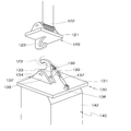
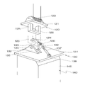
즉, 도 1 내지 도 5에 나타내 보인 바와 같이 본 출원인이 선출원한 오거 드릴링 머신(100)은, 작업위치로 이동하면서 동력을 공급하는 크레인(111)의 상부에 회동장치로 회동되는 러더(112)를 형성하고, 러더(112)의 상부에 크레인(111)의 동력으로 작동하는 와이어(117)를 구비한 복수의 구동풀리(116)를 풀리브라켓(115)으로 고정 형성하며, 러더(112)의 천공측으로 러더가이드(114)를 형성한 러더부(110)와, 상기 러더부(110)의 와이어(117)가 안치된 이송풀리(122)를 이송브라켓(121)의 상부에 형성하고, 이송브라켓(121)의 일측으로 러더가이드(114)에 결합 가이드 되는 이송가이드(124)를 형성하며, 이송브라켓(121)의 하부에 이송결합후크(123)를 형성한 이송부(120)와, 상기 이송부(120)의 이송결합후크(123)에 결합되도록 고정결합후크(133)를 고정프레임(131)의 상부에 힌지고정구에 구비된 후크힌지(134)로 힌지고정하고, 고정프레임(131)의 일측으로 러더가이드(114)에 결합되어 상하 작동 시 가이드되는 고정가이드(132)를 형성하며, 고정결합후크(133)의 일측으로 실린더고정힌지(138)로 고정프레임(131)에 고정 결합된 작동실린더(137)의 실린더로드(139)를 후크작동 힌지(136)로 힌지 결합하여 작동실린더(137)의 작동으로 고정결합후크(133)가 후크힌지를 중심으로 회전하면서 이송부(120)의 이송결합후크(123)와 결합과 해체를 작동하도록 형성한 이송고정부(130)와, 상기 이송고정부(130)의 고정프레임(131)의 하부에 오거드릴(141)을 구동하면 상하로 작동하는 상하작동실린더(144)를 형성한 드릴구동부의 일측으로 러더가이드(114)에 결합 가이드되는 구동가이드(143)를 형성하고, 드릴구동부의 하부에 구동되는 외측에 케이싱(146)을 구비한 오거드릴(141)을 형성한 오거부(140)를 포함하는 오거 드릴링 머신에 있어서. 상기 오거부(140)는 케이싱(145)의 하부 일측으로 가이드홈(147)이 형성된 연장가이드(146)를 하부 측으로 연장형성하여 오거드릴(141)로 천공된 구멍에 타설되는 타설체(1)(시트파일)를 가이드하도록 구성하는 것을 특징으로 하고 있다.That is, as shown in FIGS. 1 to 5, the
그러나 이러한 본출원인이 선출원한 오거드릴링 머신에 있어서, 시트파일 연결고리와 연장가이드의 가이드홈간의 마찰로 인하여 천공후 케이싱 인발에 시간이 많이 걸리는 문제점을 내재하고 있다.However, in the auger drilling machine of the present applicant, there is a problem that it takes a lot of time to draw the casing after drilling due to friction between the seat pile connecting ring and the guide groove of the extension guide.
또한 시트파일이 아닌 타설체로써 사각 콘크리트 파일을 시공하고자 할 경우에는 상기한 문제점은 매우 크게 대두된다 할 것이다.In addition, when attempting to construct a rectangular concrete pile as a cast body rather than a sheet pile, the above problems will be very large.
본 발명은 상술한 본 출원인이 선출원한 오거 드릴링 머신의 문제점을 해결하고자 창출된 것으로서, 기존 가이드 홈이 갖고 있는 장점에 더하여 사각 콘크리트 파일와 연장 가이드의 가이드 홈간의 마찰을 방지시킬 수 있으며, 특히 그 시공이 안정되게 이루어져 작업시간 단축과 경비절감을 도모할 수 있는 오거 드릴링 머신의 사각 콘크리트 파일 시공방법을 제공함에 그 목적이 있다.The present invention was created to solve the problems of the above-described auger drilling machine previously filed by the present applicant, in addition to the advantages of the existing guide groove can prevent friction between the guide groove of the rectangular concrete pile and the extension guide, in particular the construction The purpose is to provide a square concrete pile construction method of the auger drilling machine that can be made stable to shorten the working time and cost reduction.
이와같은 목적을 달성하기 위하여 본 발명에 따른 오거 드릴링 머신의 사각 콘크리트 파일 시공방법은, 오거부의 케이싱 하부 일측으로 가이드 홈이 형성된 연장 가이드를 하부측으로 연장 형성하는 공정과; 상기 연장 가이드의 가이드 홈 내측에 일정간격으로 복수의 롤러를 회전 가능하게 축 지지하는 공정과; 상기 롤러들 사이에 사각 단면 형상의 가이더를 각각 설치하는 공정과; 크레인에 바이브레터를 장착하여 시공하고자 하는 사각 콘크리트 파일을 근입하는 단계와; 근입된 사각 콘크리트 파일의 홈을 연장 가이드의 가이드 홈에 인접시키고 천공하는 공정;으로 이루어지는 것을 그 특징으로 한다.Square concrete pile construction method of the auger drilling machine according to the present invention in order to achieve the above object, the process of extending and forming an extension guide formed with a guide groove in the lower side of the casing of the auger; Axially rotatably supporting a plurality of rollers at predetermined intervals inside the guide groove of the extension guide; Providing a guider having a rectangular cross-sectional shape between the rollers; Mounting a rectangular concrete pile to be installed by mounting a vibrator on a crane; The step of adjoining and puncturing the groove of the square concrete pile in the adjacent guide guide of the extension guide; characterized in that consisting of.
본 발명의 상기 롤러들 사이에 배치된 가이더는, 금속으로 성형되며, 롤러보다 낮게 돌출되도록 설치됨과 동시에, 상기 가이더의 좌,우 외측에는 케이싱에 용접 고정되는 사각철편과 원통형 파이프로 이루어지는 보조 가이더가 더 마련되는 것에 특징이 있다.The guider disposed between the rollers of the present invention is formed of a metal, is installed to protrude lower than the roller, and at the same time the auxiliary guider made of a square iron piece and a cylindrical pipe welded to the casing on the left and right outer sides of the guider. It is characterized by being further provided.
본 발명의 상기 롤러는 사각 콘크리트 파일과 동일 단면 형상을 가지는 장구형 단면 형상을 가지며, 상호간의 사이에는 동일 형상의 철판이 개재되는 것에 특징이 있다.The roller of the present invention has a long and rectangular cross-sectional shape having the same cross-sectional shape as the rectangular concrete pile, characterized in that the iron plate of the same shape is interposed between each other.
본 발명의 상기 롤러와 연장 가이드간의 결합 축 부위에는 오링을 개재하여 된 것에 특징이 있다.An engaging shaft portion between the roller and the extension guide of the present invention is characterized in that the O-ring is interposed.
본 발명의 상기 바이브 레터상에는 사각 콘크리트 파일의 중심부에 형성된 홈에 에어를 주입할 수 있는 에어호스가 마련되는 것에 특징이 있다.The vibrating letter of the present invention is characterized in that the air hose for injecting air into the groove formed in the center of the rectangular concrete pile is provided.
상술한 바와 같이 본 발명에 따른 오거 드릴링 머신의 사각 콘크리트 파일 시공방법은, 사각 콘크리트 파일 크레인의 바이브 레터를 통해 근입하여 연장 가이드를 통해 천공 가능하고, 특히 천공 과정에서 연장 가이드 및 보조 가이드 그리고 에어호스등을 통해 안정되게 천공 가능하게 된다.As described above, the method for constructing the square concrete pile of the auger drilling machine according to the present invention may be drilled through the extension guide by entering through the vibratory letter of the square concrete pile crane, and in particular, the extension guide and the auxiliary guide and the air hose during the drilling process. It is possible to stably drill through the back.
또한 롤러의 형상과 사각 콘크리트 파일 장체의 홈간의 상호 작용에 의해 흔들림 없이 견고하게 천공 가능하다.In addition, due to the interaction between the shape of the roller and the groove of the rectangular concrete pile body, it can be drilled firmly without shaking.
도 1 내지 도 5는 본 출원인이 선출원한 오거 드릴링 머신의 구성도들.
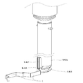
도 6은 본 발명의 요부 사시도.
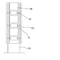
도 7은 요부 정면도.
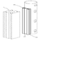
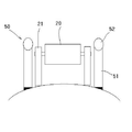
도 8은 본 발명의 요부 평면도.
도 9는 본 발명의 요부 확대 단면도.1 to 5 are schematic views of the auger drilling machine filed by the applicant.
6 is a perspective view of main parts of the present invention;
7 is a main portion front view.
8 is a plan view of main parts of the present invention;
9 is an enlarged cross-sectional view of the main portion of the present invention.
이하 본 발명에 따른 오거 드릴링 머신의 시트파일 시공방법의 바람직한 실시예를 설명하면 다음과 같다.Hereinafter, a preferred embodiment of the sheet pile construction method of the auger drilling machine according to the present invention will be described.
그리고 이하에서는 본출원인이 선출원한 도 1 내지 도 5를 참조하여 설명한다.Hereinafter, the present applicant will be described with reference to FIGS. 1 to 5.
먼저 도 1 내지 도 5를 참조하여 설명하면, 오거 드릴링 머신(100)은, 작업위치로 이동하면서 동력을 공급하는 크레인(111)의 상부에 회동장치로 회동되는 러더(112)를 형성하고, 러더(112)의 상부에 크레인(111)의 동력으로 작동하는 와이어(117)를 구비한 복수의 구동풀리(116)를 풀리브라켓(115)으로 고정 형성하며, 러더(112)의 천공측으로 러더가이드(114)를 형성한 러더부(110)와, First, referring to FIGS. 1 to 5, the
상기 러더부(110)의 와이어(117)가 안치된 이송풀리(122)를 이송브라켓(121)의 상부에 형성하고, 이송브라켓(121)의 일측으로 러더가이드(114)에 결합 가이드 되는 이송가이드(124)를 형성하며, 이송브라켓(121)의 하부에 이송결합후크(123)를 형성한 이송부(120)와,
상기 이송부(120)의 이송결합후크(123)에 결합되도록 고정결합후크(133)를 고정프레임(131)의 상부에 힌지고정구에 구비된 후크힌지(134)로 힌지고정하고, 고정프레임(131)의 일측으로 러더가이드(114)에 결합되어 상하 작동 시 가이드되는 고정가이드(132)를 형성하며, 고정결합후크(133)의 일측으로 실린더고정힌지(138)로 고정프레임(131)에 고정 결합된 작동실린더(137)의 실린더로드(139)를 후크작동 힌지(136)로 힌지 결합하여 작동실린더(137)의 작동으로 고정결합후크(133)가 후크힌지를 중심으로 회전하면서 이송부(120)의 이송결합후크(123)와 결합과 해체를 작동하도록 형성한 이송고정부(130)와, The fixed
상기 이송고정부(130)의 고정프레임(131)의 하부에 오거드릴(141)을 구동하면 상하로 작동하는 상하작동실린더(144)를 형성한 드릴구동부의 일측으로 러더가이드(114)에 결합 가이드되는 구동가이드(143)를 형성하고, 드릴구동부의 하부에 구동되는 외측에 케이싱(146)을 구비한 오거드릴(141)을 형성한 오거부(140)를 포함하여 구성된다. When the
이때 오거부(140)는 실질적으로 본 발명의 특징적인 요소를 갖고 있는 것으로서, 케이싱(145)의 하부 일측으로 가이드홈(11)이 형성된 연장가이드(10)를 하부 측으로 연장형성하여 오거드릴(141)로 천공된 구멍에 타설되는 타설체(1)(사각 콘크리트 파일,시트파일)를 가이드하도록 구성된다.At this time, the
한편, 연장가이드(10)를 연장 형성하여 가이드홈(11)을 통해 사각 콘크리트 파일(1)을 가이드함에 있어서는, 상호간의 마찰이 발생될 우려가 야기된다.On the other hand, in guiding the
이를 방지하기 위한 것으로서, 연장 가이드(10)의 가이드 홈(11) 내측에 일정간격으로 복수의 롤러(20)를 회전 가능하게 축 지지시킨다.In order to prevent this, the plurality of
또한 롤러(20)들 사이에 연장 가이드(10)이 하면에는 충격 분산등을 위한 사각 가이더(30)를 개재한다.In addition, the lower surface of the extension guide 10 between the
한편, 타설체 즉, 사각 콘크리트 파일(1)은 크레인(111)에 마련된 바이브 레터(40)를 통해 근입함이 바람직하며, 이 사각 콘크리트 파일(1)은 연장 가이드(10)의 가이드 홈(11)에 인접시킨상태에서 천공된다.On the other hand, the cast body, that is, the rectangular concrete pile (1) is preferably entered through the vibrating letter 40 provided in the
이때 상술한 롤러(20)를 축 지지하는 가이드(21)는 금속으로 성형되며, 롤러(20)보다 낮게 돌출되도록 설치된다.At this time, the
또한 가이더(21)의 좌,우 외측에는 케이싱(146)에 용접 고정되는 사각철편(51)과 원통형 파이프(52)로 이루어지는 보조 가이더(50)가 더 마련되는 바, 이 보조 가이더(50)는 천공되는 사각 콘크리트 파일(1)의 측면을 안내하는 기능을 수행한다.In addition, the left and right outer side of the
이에 더하여 롤러(20)는 사각 콘크리트 파일(1)과 동일 단면 형상을 가지는 장구형 단면 형상을 가지며, 상호간의 사이에는 동일 형상의 철판(2)이 개재되도록 함이 마찰력의 감소등을 도모할 수 있어 바람직할 것이다.In addition, the
그리고 롤러(20)와 연장 가이드간(10)의 결합 축 부위에는 오링(O)개재하여 롤러(20)가 장시간 동작될 수 있도록 함이 바람직할 것이다.And it will be desirable to allow the
한편, 좀더 사각 콘크리트 파일(1)의 안정된 근입을 위하여 바이브 레터(40)상에는 사각 콘크리트 파일(1)의 중심부에 형성된 홈에 에어를 주입할 수 있는 에어호스(60)가 마련된다.On the other hand, the air hose 60 for injecting air into the groove formed in the center of the rectangular concrete pile (1) is provided on the vibrator letter 40 for a more stable entrance of the rectangular concrete pile (1).
이와같은 본 발명은, 바이브 레터(40)를 통해 근입된 타설체 즉, 사각 콘크리트 파일(1)이 연장 가이더(10)의 가이드 홈(11)에 개재된 다수의 롤러(20)와 사각 가이더(30) 또한 철편(51)과 원통형 파이프(52)로 이루어진 보조 가이더(50)에 의해 흔들림 없이 안정되게 천공된다.The present invention as described above, a plurality of
또한 그 과정에서 바이브 레터(40)상의 에어호스(60)를 통해 사각 콘크리트 파일(1)의 중심부에 형성된 구멍으로 에어가 유입됨으로써 이를 통해서도 보다 안정된 시공이 가능하게 된다.
In addition, the air flows into the hole formed in the center of the
한편, 본 발명은, 상기한 구체적인 예에 대해서만 상세히 설명하였지만 본 발명의 기술사상 범위내에서 다양한 변형 및 수정이 가능함은 당업자에게 있어서 명백한 것이며, 이러한 변형 및 수정이 청구된 특허청구범위에 속하는 것은 당연한 것이다.Meanwhile, the present invention has been described in detail only with respect to the specific examples described above, but it is obvious to those skilled in the art that various modifications and changes are possible within the technical scope of the present invention, and it is natural that such modifications and modifications fall within the claims. will be.
*도면의 주요 부분에 대한 부호의 설명
10 : 연장가이드 11 : 가이드 홈
20 : 롤러 30 : 가이더
40 : 바이브 레터 50 : 보조 가이더
51 : 철편 52 : 원통형 파이프
60 : 에어 호스
O : 오링 140 : 오거부
145 : 케이싱 1 : 사각 콘크리트 파일DESCRIPTION OF THE REFERENCE NUMERALS
10: extension guide 11: guide groove
20: roller 30: guider
40: Vibe Letter 50: Assistant Guider
51: iron piece 52: cylindrical pipe
60: air hose
O: O-ring 140: Ogre
145: casing 1: square concrete pile
Claims (5)
상기 연장 가이드의 가이드 홈 내측에 일정간격으로 복수의 롤러를 회전 가능하게 축 지지하는 공정과;
상기 롤러들 사이에 사각 단면 형상의 가이더를 각각 설치하는 공정과;
크레인에 바이브 레터를 장착하여 시공하고자 하는 사각 콘크리트 파일을 근입하는 단계와;
근입된 사각 콘크리트 파일의 홈을 연장 가이드의 가이드 홈에 인접시키고 천공하는 공정;으로 이루어지는 것을 특징으로 하는 오거 드릴링 머신을 통한 사각 콘크리트 파일 시공방법.A step of extending and forming an extension guide having a guide groove formed on one side of the casing lower portion of the auger;
Axially rotatably supporting a plurality of rollers at predetermined intervals inside the guide groove of the extension guide;
Providing a guider having a rectangular cross-sectional shape between the rollers;
Mounting a rectangular concrete pile to be installed by mounting a vibratory letter to a crane;
A method of constructing a square concrete pile through an auger drilling machine, characterized in that the step of adjoining the perforated groove of the rectangular concrete pile into the guide groove of the extension guide.
상기 롤러들 사이에 배치된 가이더는, 금속으로 성형되며, 롤러보다 낮게 돌출되도록 설치됨과 동시에,
상기 가이더의 좌,우 외측에는 케이싱에 용접 고정되는 사각철편과 원통형 파이프로 이루어지는 보조 가이더가 더 마련되는 것을 특징으로 하는 오거 드릴링 머신을 통한 사각 콘크리트 파일 시공방법.The method of claim 1,
The guider disposed between the rollers is formed of metal and installed to protrude lower than the rollers.
Square concrete pile construction method through the auger drilling machine, characterized in that the left and right outer side of the guider is further provided with an auxiliary guider consisting of a square iron piece and a cylindrical pipe welded to the casing.
상기 롤러는 사각 콘크리트 파일과 동일 단면 형상을 가지는 장구형 단면 형상을 가지며, 상호간의 사이에는 동일 형상의 철판이 개재되는 것을 특징으로 하는 오거 드릴링 머신을 통한 사각 콘크리트 파일 시공방법, The method of claim 1,
The roller is a rectangular concrete pile construction method through the auger drilling machine, characterized in that it has a long and rectangular cross-sectional shape having the same cross-sectional shape and the rectangular concrete pile, and the iron plate of the same shape between each other,
상기 롤러와 연장 가이드간의 결합 축 부위에는 오링을 개재하여 된 것을 특징으로 하는 오거 드릴링 머신을 통한 시트파일 시공방법.The method of claim 1,
A method of constructing a sheet pile through an auger drilling machine, characterized in that the coupling shaft portion between the roller and the extension guide is interposed through an O-ring.
상기 바이브 레터상에는 사각 콘크리트 파일의 중심부에 형성된 홈에 에어를 주입할 수 있는 에어호스가 마련되는 것을 특징으로 하는 오거 드릴링 머신을 통한 사각 콘크리트 파일 시공방법.
The method of claim 1,
The vibrating letter is a square concrete pile construction method through an auger drilling machine, characterized in that the air hose for injecting air into the groove formed in the center of the square concrete pile is provided.
Priority Applications (1)
| Application Number | Priority Date | Filing Date | Title |
|---|---|---|---|
| KR1020110095322A KR20130031624A (en) | 2011-09-21 | 2011-09-21 | Concrete pile setting method by utilizing an auger drilling maachine |
Applications Claiming Priority (1)
| Application Number | Priority Date | Filing Date | Title |
|---|---|---|---|
| KR1020110095322A KR20130031624A (en) | 2011-09-21 | 2011-09-21 | Concrete pile setting method by utilizing an auger drilling maachine |
Publications (1)
| Publication Number | Publication Date |
|---|---|
| KR20130031624A true KR20130031624A (en) | 2013-03-29 |
Family
ID=48180728
Family Applications (1)
| Application Number | Title | Priority Date | Filing Date |
|---|---|---|---|
| KR1020110095322A Ceased KR20130031624A (en) | 2011-09-21 | 2011-09-21 | Concrete pile setting method by utilizing an auger drilling maachine |
Country Status (1)
| Country | Link |
|---|---|
| KR (1) | KR20130031624A (en) |
Cited By (2)
| Publication number | Priority date | Publication date | Assignee | Title |
|---|---|---|---|---|
| CN104674872A (en) * | 2015-01-17 | 2015-06-03 | 宋姝娴 | Excavator drill for square holes |
| CN109989709A (en) * | 2019-04-03 | 2019-07-09 | 江苏省建筑工程集团有限公司 | A kind of electric screw drilling machine |
-
2011
- 2011-09-21 KR KR1020110095322A patent/KR20130031624A/en not_active Ceased
Cited By (2)
| Publication number | Priority date | Publication date | Assignee | Title |
|---|---|---|---|---|
| CN104674872A (en) * | 2015-01-17 | 2015-06-03 | 宋姝娴 | Excavator drill for square holes |
| CN109989709A (en) * | 2019-04-03 | 2019-07-09 | 江苏省建筑工程集团有限公司 | A kind of electric screw drilling machine |
Similar Documents
| Publication | Publication Date | Title |
|---|---|---|
| CN103669351B (en) | Full-stroke hole-leading hydraulic static pile driver | |
| JP6467693B2 (en) | Core drill equipment for excavator installation | |
| CN102852457B (en) | Follow-up drilling machine for down-hole hammer casing pipe | |
| JP2009532601A (en) | Drilling tools | |
| JP6085484B2 (en) | Pile driver | |
| CN103726785B (en) | Rotary drilling rig with hydraulic breaker unit | |
| KR101851105B1 (en) | A middle pulley assembly for duide of hammer wire in pile driver | |
| KR20070016292A (en) | File construction device that can simultaneously drill and drive | |
| JP6085485B2 (en) | Pile driver | |
| CN102112685A (en) | Piling device | |
| JP2012031680A (en) | Device for foundation construction | |
| CN110344414A (en) | A kind of pilot hole plant stake piling all-in-one machine | |
| CN210422486U (en) | Immersed tube gravel pile machine | |
| KR101094276B1 (en) | Sheet pile construction method through auger drilling machine | |
| KR20220000803A (en) | File construction apparatus capable of simultaneous achievement of hole-boring and vibrating | |
| KR102178354B1 (en) | Pile pullout apparatus | |
| CN207959210U (en) | A kind of civil engineering piling machine | |
| CN107461145A (en) | A kind of construction piling equipment | |
| JP2006052640A (en) | Soil working method and soil working machine | |
| CN205990887U (en) | Light Inspection Hole Drilling Rig | |
| KR100927850B1 (en) | Auger Auger | |
| KR200444957Y1 (en) | Auger Drilling Machine | |
| KR20110048964A (en) | Rock Drilling Device | |
| KR101005359B1 (en) | Depth Drilling Rig | |
| CN113006692A (en) | Rotary drilling rig and construction method thereof |
Legal Events
| Date | Code | Title | Description |
|---|---|---|---|
| A201 | Request for examination | ||
| PA0109 | Patent application |
Patent event code: PA01091R01D Comment text: Patent Application Patent event date: 20110921 |
|
| PA0201 | Request for examination | ||
| E902 | Notification of reason for refusal | ||
| PE0902 | Notice of grounds for rejection |
Comment text: Notification of reason for refusal Patent event date: 20130302 Patent event code: PE09021S01D |
|
| PG1501 | Laying open of application | ||
| E601 | Decision to refuse application | ||
| PE0601 | Decision on rejection of patent |
Patent event date: 20130618 Comment text: Decision to Refuse Application Patent event code: PE06012S01D Patent event date: 20130302 Comment text: Notification of reason for refusal Patent event code: PE06011S01I |