KR20120117978A - Ceramic composite materials containing carbon nanotube-infused fiber materials and methods for production thereof - Google Patents
Ceramic composite materials containing carbon nanotube-infused fiber materials and methods for production thereof Download PDFInfo
- Publication number
- KR20120117978A KR20120117978A KR20127012546A KR20127012546A KR20120117978A KR 20120117978 A KR20120117978 A KR 20120117978A KR 20127012546 A KR20127012546 A KR 20127012546A KR 20127012546 A KR20127012546 A KR 20127012546A KR 20120117978 A KR20120117978 A KR 20120117978A
- Authority
- KR
- South Korea
- Prior art keywords
- carbon nanotube
- fiber material
- carbon
- carbon nanotubes
- composite material
- Prior art date
Links
Images

Classifications
-
- C—CHEMISTRY; METALLURGY
- C04—CEMENTS; CONCRETE; ARTIFICIAL STONE; CERAMICS; REFRACTORIES
- C04B—LIME, MAGNESIA; SLAG; CEMENTS; COMPOSITIONS THEREOF, e.g. MORTARS, CONCRETE OR LIKE BUILDING MATERIALS; ARTIFICIAL STONE; CERAMICS; REFRACTORIES; TREATMENT OF NATURAL STONE
- C04B35/00—Shaped ceramic products characterised by their composition; Ceramics compositions; Processing powders of inorganic compounds preparatory to the manufacturing of ceramic products
- C04B35/622—Forming processes; Processing powders of inorganic compounds preparatory to the manufacturing of ceramic products
- C04B35/626—Preparing or treating the powders individually or as batches ; preparing or treating macroscopic reinforcing agents for ceramic products, e.g. fibres; mechanical aspects section B
- C04B35/628—Coating the powders or the macroscopic reinforcing agents
- C04B35/62889—Coating the powders or the macroscopic reinforcing agents with a discontinuous coating layer
-
- B—PERFORMING OPERATIONS; TRANSPORTING
- B32—LAYERED PRODUCTS
- B32B—LAYERED PRODUCTS, i.e. PRODUCTS BUILT-UP OF STRATA OF FLAT OR NON-FLAT, e.g. CELLULAR OR HONEYCOMB, FORM
- B32B15/00—Layered products comprising a layer of metal
- B32B15/14—Layered products comprising a layer of metal next to a fibrous or filamentary layer
-
- B—PERFORMING OPERATIONS; TRANSPORTING
- B82—NANOTECHNOLOGY
- B82Y—SPECIFIC USES OR APPLICATIONS OF NANOSTRUCTURES; MEASUREMENT OR ANALYSIS OF NANOSTRUCTURES; MANUFACTURE OR TREATMENT OF NANOSTRUCTURES
- B82Y30/00—Nanotechnology for materials or surface science, e.g. nanocomposites
-
- C—CHEMISTRY; METALLURGY
- C04—CEMENTS; CONCRETE; ARTIFICIAL STONE; CERAMICS; REFRACTORIES
- C04B—LIME, MAGNESIA; SLAG; CEMENTS; COMPOSITIONS THEREOF, e.g. MORTARS, CONCRETE OR LIKE BUILDING MATERIALS; ARTIFICIAL STONE; CERAMICS; REFRACTORIES; TREATMENT OF NATURAL STONE
- C04B20/00—Use of materials as fillers for mortars, concrete or artificial stone according to more than one of groups C04B14/00 - C04B18/00 and characterised by shape or grain distribution; Treatment of materials according to more than one of the groups C04B14/00 - C04B18/00 specially adapted to enhance their filling properties in mortars, concrete or artificial stone; Expanding or defibrillating materials
- C04B20/10—Coating or impregnating
- C04B20/12—Multiple coating or impregnating
-
- C—CHEMISTRY; METALLURGY
- C04—CEMENTS; CONCRETE; ARTIFICIAL STONE; CERAMICS; REFRACTORIES
- C04B—LIME, MAGNESIA; SLAG; CEMENTS; COMPOSITIONS THEREOF, e.g. MORTARS, CONCRETE OR LIKE BUILDING MATERIALS; ARTIFICIAL STONE; CERAMICS; REFRACTORIES; TREATMENT OF NATURAL STONE
- C04B28/00—Compositions of mortars, concrete or artificial stone, containing inorganic binders or the reaction product of an inorganic and an organic binder, e.g. polycarboxylate cements
- C04B28/02—Compositions of mortars, concrete or artificial stone, containing inorganic binders or the reaction product of an inorganic and an organic binder, e.g. polycarboxylate cements containing hydraulic cements other than calcium sulfates
- C04B28/04—Portland cements
-
- C—CHEMISTRY; METALLURGY
- C04—CEMENTS; CONCRETE; ARTIFICIAL STONE; CERAMICS; REFRACTORIES
- C04B—LIME, MAGNESIA; SLAG; CEMENTS; COMPOSITIONS THEREOF, e.g. MORTARS, CONCRETE OR LIKE BUILDING MATERIALS; ARTIFICIAL STONE; CERAMICS; REFRACTORIES; TREATMENT OF NATURAL STONE
- C04B35/00—Shaped ceramic products characterised by their composition; Ceramics compositions; Processing powders of inorganic compounds preparatory to the manufacturing of ceramic products
- C04B35/01—Shaped ceramic products characterised by their composition; Ceramics compositions; Processing powders of inorganic compounds preparatory to the manufacturing of ceramic products based on oxide ceramics
- C04B35/10—Shaped ceramic products characterised by their composition; Ceramics compositions; Processing powders of inorganic compounds preparatory to the manufacturing of ceramic products based on oxide ceramics based on aluminium oxide
- C04B35/111—Fine ceramics
- C04B35/117—Composites
-
- C—CHEMISTRY; METALLURGY
- C04—CEMENTS; CONCRETE; ARTIFICIAL STONE; CERAMICS; REFRACTORIES
- C04B—LIME, MAGNESIA; SLAG; CEMENTS; COMPOSITIONS THEREOF, e.g. MORTARS, CONCRETE OR LIKE BUILDING MATERIALS; ARTIFICIAL STONE; CERAMICS; REFRACTORIES; TREATMENT OF NATURAL STONE
- C04B35/00—Shaped ceramic products characterised by their composition; Ceramics compositions; Processing powders of inorganic compounds preparatory to the manufacturing of ceramic products
- C04B35/01—Shaped ceramic products characterised by their composition; Ceramics compositions; Processing powders of inorganic compounds preparatory to the manufacturing of ceramic products based on oxide ceramics
- C04B35/16—Shaped ceramic products characterised by their composition; Ceramics compositions; Processing powders of inorganic compounds preparatory to the manufacturing of ceramic products based on oxide ceramics based on silicates other than clay
- C04B35/18—Shaped ceramic products characterised by their composition; Ceramics compositions; Processing powders of inorganic compounds preparatory to the manufacturing of ceramic products based on oxide ceramics based on silicates other than clay rich in aluminium oxide
- C04B35/185—Mullite 3Al2O3-2SiO2
-
- C—CHEMISTRY; METALLURGY
- C04—CEMENTS; CONCRETE; ARTIFICIAL STONE; CERAMICS; REFRACTORIES
- C04B—LIME, MAGNESIA; SLAG; CEMENTS; COMPOSITIONS THEREOF, e.g. MORTARS, CONCRETE OR LIKE BUILDING MATERIALS; ARTIFICIAL STONE; CERAMICS; REFRACTORIES; TREATMENT OF NATURAL STONE
- C04B35/00—Shaped ceramic products characterised by their composition; Ceramics compositions; Processing powders of inorganic compounds preparatory to the manufacturing of ceramic products
- C04B35/01—Shaped ceramic products characterised by their composition; Ceramics compositions; Processing powders of inorganic compounds preparatory to the manufacturing of ceramic products based on oxide ceramics
- C04B35/46—Shaped ceramic products characterised by their composition; Ceramics compositions; Processing powders of inorganic compounds preparatory to the manufacturing of ceramic products based on oxide ceramics based on titanium oxides or titanates
- C04B35/462—Shaped ceramic products characterised by their composition; Ceramics compositions; Processing powders of inorganic compounds preparatory to the manufacturing of ceramic products based on oxide ceramics based on titanium oxides or titanates based on titanates
- C04B35/465—Shaped ceramic products characterised by their composition; Ceramics compositions; Processing powders of inorganic compounds preparatory to the manufacturing of ceramic products based on oxide ceramics based on titanium oxides or titanates based on titanates based on alkaline earth metal titanates
- C04B35/468—Shaped ceramic products characterised by their composition; Ceramics compositions; Processing powders of inorganic compounds preparatory to the manufacturing of ceramic products based on oxide ceramics based on titanium oxides or titanates based on titanates based on alkaline earth metal titanates based on barium titanates
- C04B35/4682—Shaped ceramic products characterised by their composition; Ceramics compositions; Processing powders of inorganic compounds preparatory to the manufacturing of ceramic products based on oxide ceramics based on titanium oxides or titanates based on titanates based on alkaline earth metal titanates based on barium titanates based on BaTiO3 perovskite phase
-
- C—CHEMISTRY; METALLURGY
- C04—CEMENTS; CONCRETE; ARTIFICIAL STONE; CERAMICS; REFRACTORIES
- C04B—LIME, MAGNESIA; SLAG; CEMENTS; COMPOSITIONS THEREOF, e.g. MORTARS, CONCRETE OR LIKE BUILDING MATERIALS; ARTIFICIAL STONE; CERAMICS; REFRACTORIES; TREATMENT OF NATURAL STONE
- C04B35/00—Shaped ceramic products characterised by their composition; Ceramics compositions; Processing powders of inorganic compounds preparatory to the manufacturing of ceramic products
- C04B35/515—Shaped ceramic products characterised by their composition; Ceramics compositions; Processing powders of inorganic compounds preparatory to the manufacturing of ceramic products based on non-oxide ceramics
- C04B35/56—Shaped ceramic products characterised by their composition; Ceramics compositions; Processing powders of inorganic compounds preparatory to the manufacturing of ceramic products based on non-oxide ceramics based on carbides or oxycarbides
- C04B35/5607—Shaped ceramic products characterised by their composition; Ceramics compositions; Processing powders of inorganic compounds preparatory to the manufacturing of ceramic products based on non-oxide ceramics based on carbides or oxycarbides based on refractory metal carbides
- C04B35/5611—Shaped ceramic products characterised by their composition; Ceramics compositions; Processing powders of inorganic compounds preparatory to the manufacturing of ceramic products based on non-oxide ceramics based on carbides or oxycarbides based on refractory metal carbides based on titanium carbides
-
- C—CHEMISTRY; METALLURGY
- C04—CEMENTS; CONCRETE; ARTIFICIAL STONE; CERAMICS; REFRACTORIES
- C04B—LIME, MAGNESIA; SLAG; CEMENTS; COMPOSITIONS THEREOF, e.g. MORTARS, CONCRETE OR LIKE BUILDING MATERIALS; ARTIFICIAL STONE; CERAMICS; REFRACTORIES; TREATMENT OF NATURAL STONE
- C04B35/00—Shaped ceramic products characterised by their composition; Ceramics compositions; Processing powders of inorganic compounds preparatory to the manufacturing of ceramic products
- C04B35/515—Shaped ceramic products characterised by their composition; Ceramics compositions; Processing powders of inorganic compounds preparatory to the manufacturing of ceramic products based on non-oxide ceramics
- C04B35/56—Shaped ceramic products characterised by their composition; Ceramics compositions; Processing powders of inorganic compounds preparatory to the manufacturing of ceramic products based on non-oxide ceramics based on carbides or oxycarbides
- C04B35/5607—Shaped ceramic products characterised by their composition; Ceramics compositions; Processing powders of inorganic compounds preparatory to the manufacturing of ceramic products based on non-oxide ceramics based on carbides or oxycarbides based on refractory metal carbides
- C04B35/5626—Shaped ceramic products characterised by their composition; Ceramics compositions; Processing powders of inorganic compounds preparatory to the manufacturing of ceramic products based on non-oxide ceramics based on carbides or oxycarbides based on refractory metal carbides based on tungsten carbides
-
- C—CHEMISTRY; METALLURGY
- C04—CEMENTS; CONCRETE; ARTIFICIAL STONE; CERAMICS; REFRACTORIES
- C04B—LIME, MAGNESIA; SLAG; CEMENTS; COMPOSITIONS THEREOF, e.g. MORTARS, CONCRETE OR LIKE BUILDING MATERIALS; ARTIFICIAL STONE; CERAMICS; REFRACTORIES; TREATMENT OF NATURAL STONE
- C04B35/00—Shaped ceramic products characterised by their composition; Ceramics compositions; Processing powders of inorganic compounds preparatory to the manufacturing of ceramic products
- C04B35/515—Shaped ceramic products characterised by their composition; Ceramics compositions; Processing powders of inorganic compounds preparatory to the manufacturing of ceramic products based on non-oxide ceramics
- C04B35/56—Shaped ceramic products characterised by their composition; Ceramics compositions; Processing powders of inorganic compounds preparatory to the manufacturing of ceramic products based on non-oxide ceramics based on carbides or oxycarbides
- C04B35/565—Shaped ceramic products characterised by their composition; Ceramics compositions; Processing powders of inorganic compounds preparatory to the manufacturing of ceramic products based on non-oxide ceramics based on carbides or oxycarbides based on silicon carbide
-
- C—CHEMISTRY; METALLURGY
- C04—CEMENTS; CONCRETE; ARTIFICIAL STONE; CERAMICS; REFRACTORIES
- C04B—LIME, MAGNESIA; SLAG; CEMENTS; COMPOSITIONS THEREOF, e.g. MORTARS, CONCRETE OR LIKE BUILDING MATERIALS; ARTIFICIAL STONE; CERAMICS; REFRACTORIES; TREATMENT OF NATURAL STONE
- C04B35/00—Shaped ceramic products characterised by their composition; Ceramics compositions; Processing powders of inorganic compounds preparatory to the manufacturing of ceramic products
- C04B35/515—Shaped ceramic products characterised by their composition; Ceramics compositions; Processing powders of inorganic compounds preparatory to the manufacturing of ceramic products based on non-oxide ceramics
- C04B35/58—Shaped ceramic products characterised by their composition; Ceramics compositions; Processing powders of inorganic compounds preparatory to the manufacturing of ceramic products based on non-oxide ceramics based on borides, nitrides, i.e. nitrides, oxynitrides, carbonitrides or oxycarbonitrides or silicides
- C04B35/58007—Shaped ceramic products characterised by their composition; Ceramics compositions; Processing powders of inorganic compounds preparatory to the manufacturing of ceramic products based on non-oxide ceramics based on borides, nitrides, i.e. nitrides, oxynitrides, carbonitrides or oxycarbonitrides or silicides based on refractory metal nitrides
- C04B35/58014—Shaped ceramic products characterised by their composition; Ceramics compositions; Processing powders of inorganic compounds preparatory to the manufacturing of ceramic products based on non-oxide ceramics based on borides, nitrides, i.e. nitrides, oxynitrides, carbonitrides or oxycarbonitrides or silicides based on refractory metal nitrides based on titanium nitrides, e.g. TiAlON
-
- C—CHEMISTRY; METALLURGY
- C04—CEMENTS; CONCRETE; ARTIFICIAL STONE; CERAMICS; REFRACTORIES
- C04B—LIME, MAGNESIA; SLAG; CEMENTS; COMPOSITIONS THEREOF, e.g. MORTARS, CONCRETE OR LIKE BUILDING MATERIALS; ARTIFICIAL STONE; CERAMICS; REFRACTORIES; TREATMENT OF NATURAL STONE
- C04B35/00—Shaped ceramic products characterised by their composition; Ceramics compositions; Processing powders of inorganic compounds preparatory to the manufacturing of ceramic products
- C04B35/515—Shaped ceramic products characterised by their composition; Ceramics compositions; Processing powders of inorganic compounds preparatory to the manufacturing of ceramic products based on non-oxide ceramics
- C04B35/58—Shaped ceramic products characterised by their composition; Ceramics compositions; Processing powders of inorganic compounds preparatory to the manufacturing of ceramic products based on non-oxide ceramics based on borides, nitrides, i.e. nitrides, oxynitrides, carbonitrides or oxycarbonitrides or silicides
- C04B35/58042—Shaped ceramic products characterised by their composition; Ceramics compositions; Processing powders of inorganic compounds preparatory to the manufacturing of ceramic products based on non-oxide ceramics based on borides, nitrides, i.e. nitrides, oxynitrides, carbonitrides or oxycarbonitrides or silicides based on iron group metals nitrides
-
- C—CHEMISTRY; METALLURGY
- C04—CEMENTS; CONCRETE; ARTIFICIAL STONE; CERAMICS; REFRACTORIES
- C04B—LIME, MAGNESIA; SLAG; CEMENTS; COMPOSITIONS THEREOF, e.g. MORTARS, CONCRETE OR LIKE BUILDING MATERIALS; ARTIFICIAL STONE; CERAMICS; REFRACTORIES; TREATMENT OF NATURAL STONE
- C04B35/00—Shaped ceramic products characterised by their composition; Ceramics compositions; Processing powders of inorganic compounds preparatory to the manufacturing of ceramic products
- C04B35/515—Shaped ceramic products characterised by their composition; Ceramics compositions; Processing powders of inorganic compounds preparatory to the manufacturing of ceramic products based on non-oxide ceramics
- C04B35/58—Shaped ceramic products characterised by their composition; Ceramics compositions; Processing powders of inorganic compounds preparatory to the manufacturing of ceramic products based on non-oxide ceramics based on borides, nitrides, i.e. nitrides, oxynitrides, carbonitrides or oxycarbonitrides or silicides
- C04B35/5805—Shaped ceramic products characterised by their composition; Ceramics compositions; Processing powders of inorganic compounds preparatory to the manufacturing of ceramic products based on non-oxide ceramics based on borides, nitrides, i.e. nitrides, oxynitrides, carbonitrides or oxycarbonitrides or silicides based on borides
- C04B35/58064—Shaped ceramic products characterised by their composition; Ceramics compositions; Processing powders of inorganic compounds preparatory to the manufacturing of ceramic products based on non-oxide ceramics based on borides, nitrides, i.e. nitrides, oxynitrides, carbonitrides or oxycarbonitrides or silicides based on borides based on refractory borides
- C04B35/58071—Shaped ceramic products characterised by their composition; Ceramics compositions; Processing powders of inorganic compounds preparatory to the manufacturing of ceramic products based on non-oxide ceramics based on borides, nitrides, i.e. nitrides, oxynitrides, carbonitrides or oxycarbonitrides or silicides based on borides based on refractory borides based on titanium borides
-
- C—CHEMISTRY; METALLURGY
- C04—CEMENTS; CONCRETE; ARTIFICIAL STONE; CERAMICS; REFRACTORIES
- C04B—LIME, MAGNESIA; SLAG; CEMENTS; COMPOSITIONS THEREOF, e.g. MORTARS, CONCRETE OR LIKE BUILDING MATERIALS; ARTIFICIAL STONE; CERAMICS; REFRACTORIES; TREATMENT OF NATURAL STONE
- C04B35/00—Shaped ceramic products characterised by their composition; Ceramics compositions; Processing powders of inorganic compounds preparatory to the manufacturing of ceramic products
- C04B35/515—Shaped ceramic products characterised by their composition; Ceramics compositions; Processing powders of inorganic compounds preparatory to the manufacturing of ceramic products based on non-oxide ceramics
- C04B35/58—Shaped ceramic products characterised by their composition; Ceramics compositions; Processing powders of inorganic compounds preparatory to the manufacturing of ceramic products based on non-oxide ceramics based on borides, nitrides, i.e. nitrides, oxynitrides, carbonitrides or oxycarbonitrides or silicides
- C04B35/584—Shaped ceramic products characterised by their composition; Ceramics compositions; Processing powders of inorganic compounds preparatory to the manufacturing of ceramic products based on non-oxide ceramics based on borides, nitrides, i.e. nitrides, oxynitrides, carbonitrides or oxycarbonitrides or silicides based on silicon nitride
-
- C—CHEMISTRY; METALLURGY
- C04—CEMENTS; CONCRETE; ARTIFICIAL STONE; CERAMICS; REFRACTORIES
- C04B—LIME, MAGNESIA; SLAG; CEMENTS; COMPOSITIONS THEREOF, e.g. MORTARS, CONCRETE OR LIKE BUILDING MATERIALS; ARTIFICIAL STONE; CERAMICS; REFRACTORIES; TREATMENT OF NATURAL STONE
- C04B35/00—Shaped ceramic products characterised by their composition; Ceramics compositions; Processing powders of inorganic compounds preparatory to the manufacturing of ceramic products
- C04B35/622—Forming processes; Processing powders of inorganic compounds preparatory to the manufacturing of ceramic products
- C04B35/626—Preparing or treating the powders individually or as batches ; preparing or treating macroscopic reinforcing agents for ceramic products, e.g. fibres; mechanical aspects section B
- C04B35/62605—Treating the starting powders individually or as mixtures
- C04B35/6269—Curing of mixtures
-
- C—CHEMISTRY; METALLURGY
- C04—CEMENTS; CONCRETE; ARTIFICIAL STONE; CERAMICS; REFRACTORIES
- C04B—LIME, MAGNESIA; SLAG; CEMENTS; COMPOSITIONS THEREOF, e.g. MORTARS, CONCRETE OR LIKE BUILDING MATERIALS; ARTIFICIAL STONE; CERAMICS; REFRACTORIES; TREATMENT OF NATURAL STONE
- C04B35/00—Shaped ceramic products characterised by their composition; Ceramics compositions; Processing powders of inorganic compounds preparatory to the manufacturing of ceramic products
- C04B35/622—Forming processes; Processing powders of inorganic compounds preparatory to the manufacturing of ceramic products
- C04B35/626—Preparing or treating the powders individually or as batches ; preparing or treating macroscopic reinforcing agents for ceramic products, e.g. fibres; mechanical aspects section B
- C04B35/628—Coating the powders or the macroscopic reinforcing agents
- C04B35/62844—Coating fibres
- C04B35/62847—Coating fibres with oxide ceramics
- C04B35/62849—Silica or silicates
-
- C—CHEMISTRY; METALLURGY
- C04—CEMENTS; CONCRETE; ARTIFICIAL STONE; CERAMICS; REFRACTORIES
- C04B—LIME, MAGNESIA; SLAG; CEMENTS; COMPOSITIONS THEREOF, e.g. MORTARS, CONCRETE OR LIKE BUILDING MATERIALS; ARTIFICIAL STONE; CERAMICS; REFRACTORIES; TREATMENT OF NATURAL STONE
- C04B35/00—Shaped ceramic products characterised by their composition; Ceramics compositions; Processing powders of inorganic compounds preparatory to the manufacturing of ceramic products
- C04B35/622—Forming processes; Processing powders of inorganic compounds preparatory to the manufacturing of ceramic products
- C04B35/626—Preparing or treating the powders individually or as batches ; preparing or treating macroscopic reinforcing agents for ceramic products, e.g. fibres; mechanical aspects section B
- C04B35/628—Coating the powders or the macroscopic reinforcing agents
- C04B35/62844—Coating fibres
- C04B35/62847—Coating fibres with oxide ceramics
- C04B35/62852—Alumina or aluminates
-
- C—CHEMISTRY; METALLURGY
- C04—CEMENTS; CONCRETE; ARTIFICIAL STONE; CERAMICS; REFRACTORIES
- C04B—LIME, MAGNESIA; SLAG; CEMENTS; COMPOSITIONS THEREOF, e.g. MORTARS, CONCRETE OR LIKE BUILDING MATERIALS; ARTIFICIAL STONE; CERAMICS; REFRACTORIES; TREATMENT OF NATURAL STONE
- C04B35/00—Shaped ceramic products characterised by their composition; Ceramics compositions; Processing powders of inorganic compounds preparatory to the manufacturing of ceramic products
- C04B35/622—Forming processes; Processing powders of inorganic compounds preparatory to the manufacturing of ceramic products
- C04B35/626—Preparing or treating the powders individually or as batches ; preparing or treating macroscopic reinforcing agents for ceramic products, e.g. fibres; mechanical aspects section B
- C04B35/628—Coating the powders or the macroscopic reinforcing agents
- C04B35/62844—Coating fibres
- C04B35/62857—Coating fibres with non-oxide ceramics
- C04B35/62873—Carbon
-
- C—CHEMISTRY; METALLURGY
- C04—CEMENTS; CONCRETE; ARTIFICIAL STONE; CERAMICS; REFRACTORIES
- C04B—LIME, MAGNESIA; SLAG; CEMENTS; COMPOSITIONS THEREOF, e.g. MORTARS, CONCRETE OR LIKE BUILDING MATERIALS; ARTIFICIAL STONE; CERAMICS; REFRACTORIES; TREATMENT OF NATURAL STONE
- C04B35/00—Shaped ceramic products characterised by their composition; Ceramics compositions; Processing powders of inorganic compounds preparatory to the manufacturing of ceramic products
- C04B35/622—Forming processes; Processing powders of inorganic compounds preparatory to the manufacturing of ceramic products
- C04B35/626—Preparing or treating the powders individually or as batches ; preparing or treating macroscopic reinforcing agents for ceramic products, e.g. fibres; mechanical aspects section B
- C04B35/628—Coating the powders or the macroscopic reinforcing agents
- C04B35/62844—Coating fibres
- C04B35/62876—Coating fibres with metals
-
- C—CHEMISTRY; METALLURGY
- C04—CEMENTS; CONCRETE; ARTIFICIAL STONE; CERAMICS; REFRACTORIES
- C04B—LIME, MAGNESIA; SLAG; CEMENTS; COMPOSITIONS THEREOF, e.g. MORTARS, CONCRETE OR LIKE BUILDING MATERIALS; ARTIFICIAL STONE; CERAMICS; REFRACTORIES; TREATMENT OF NATURAL STONE
- C04B35/00—Shaped ceramic products characterised by their composition; Ceramics compositions; Processing powders of inorganic compounds preparatory to the manufacturing of ceramic products
- C04B35/622—Forming processes; Processing powders of inorganic compounds preparatory to the manufacturing of ceramic products
- C04B35/626—Preparing or treating the powders individually or as batches ; preparing or treating macroscopic reinforcing agents for ceramic products, e.g. fibres; mechanical aspects section B
- C04B35/628—Coating the powders or the macroscopic reinforcing agents
- C04B35/62894—Coating the powders or the macroscopic reinforcing agents with more than one coating layer
-
- C—CHEMISTRY; METALLURGY
- C04—CEMENTS; CONCRETE; ARTIFICIAL STONE; CERAMICS; REFRACTORIES
- C04B—LIME, MAGNESIA; SLAG; CEMENTS; COMPOSITIONS THEREOF, e.g. MORTARS, CONCRETE OR LIKE BUILDING MATERIALS; ARTIFICIAL STONE; CERAMICS; REFRACTORIES; TREATMENT OF NATURAL STONE
- C04B35/00—Shaped ceramic products characterised by their composition; Ceramics compositions; Processing powders of inorganic compounds preparatory to the manufacturing of ceramic products
- C04B35/622—Forming processes; Processing powders of inorganic compounds preparatory to the manufacturing of ceramic products
- C04B35/626—Preparing or treating the powders individually or as batches ; preparing or treating macroscopic reinforcing agents for ceramic products, e.g. fibres; mechanical aspects section B
- C04B35/628—Coating the powders or the macroscopic reinforcing agents
- C04B35/62897—Coatings characterised by their thickness
-
- C—CHEMISTRY; METALLURGY
- C04—CEMENTS; CONCRETE; ARTIFICIAL STONE; CERAMICS; REFRACTORIES
- C04B—LIME, MAGNESIA; SLAG; CEMENTS; COMPOSITIONS THEREOF, e.g. MORTARS, CONCRETE OR LIKE BUILDING MATERIALS; ARTIFICIAL STONE; CERAMICS; REFRACTORIES; TREATMENT OF NATURAL STONE
- C04B35/00—Shaped ceramic products characterised by their composition; Ceramics compositions; Processing powders of inorganic compounds preparatory to the manufacturing of ceramic products
- C04B35/71—Ceramic products containing macroscopic reinforcing agents
- C04B35/74—Ceramic products containing macroscopic reinforcing agents containing shaped metallic materials
- C04B35/76—Fibres, filaments, whiskers, platelets, or the like
-
- C—CHEMISTRY; METALLURGY
- C04—CEMENTS; CONCRETE; ARTIFICIAL STONE; CERAMICS; REFRACTORIES
- C04B—LIME, MAGNESIA; SLAG; CEMENTS; COMPOSITIONS THEREOF, e.g. MORTARS, CONCRETE OR LIKE BUILDING MATERIALS; ARTIFICIAL STONE; CERAMICS; REFRACTORIES; TREATMENT OF NATURAL STONE
- C04B35/00—Shaped ceramic products characterised by their composition; Ceramics compositions; Processing powders of inorganic compounds preparatory to the manufacturing of ceramic products
- C04B35/71—Ceramic products containing macroscopic reinforcing agents
- C04B35/78—Ceramic products containing macroscopic reinforcing agents containing non-metallic materials
- C04B35/80—Fibres, filaments, whiskers, platelets, or the like
- C04B35/82—Asbestos; Glass; Fused silica
-
- C—CHEMISTRY; METALLURGY
- C04—CEMENTS; CONCRETE; ARTIFICIAL STONE; CERAMICS; REFRACTORIES
- C04B—LIME, MAGNESIA; SLAG; CEMENTS; COMPOSITIONS THEREOF, e.g. MORTARS, CONCRETE OR LIKE BUILDING MATERIALS; ARTIFICIAL STONE; CERAMICS; REFRACTORIES; TREATMENT OF NATURAL STONE
- C04B2235/00—Aspects relating to ceramic starting mixtures or sintered ceramic products
- C04B2235/02—Composition of constituents of the starting material or of secondary phases of the final product
- C04B2235/50—Constituents or additives of the starting mixture chosen for their shape or used because of their shape or their physical appearance
- C04B2235/52—Constituents or additives characterised by their shapes
- C04B2235/5208—Fibers
- C04B2235/5216—Inorganic
- C04B2235/522—Oxidic
- C04B2235/5224—Alumina or aluminates
-
- C—CHEMISTRY; METALLURGY
- C04—CEMENTS; CONCRETE; ARTIFICIAL STONE; CERAMICS; REFRACTORIES
- C04B—LIME, MAGNESIA; SLAG; CEMENTS; COMPOSITIONS THEREOF, e.g. MORTARS, CONCRETE OR LIKE BUILDING MATERIALS; ARTIFICIAL STONE; CERAMICS; REFRACTORIES; TREATMENT OF NATURAL STONE
- C04B2235/00—Aspects relating to ceramic starting mixtures or sintered ceramic products
- C04B2235/02—Composition of constituents of the starting material or of secondary phases of the final product
- C04B2235/50—Constituents or additives of the starting mixture chosen for their shape or used because of their shape or their physical appearance
- C04B2235/52—Constituents or additives characterised by their shapes
- C04B2235/5208—Fibers
- C04B2235/5216—Inorganic
- C04B2235/524—Non-oxidic, e.g. borides, carbides, silicides or nitrides
- C04B2235/5244—Silicon carbide
-
- C—CHEMISTRY; METALLURGY
- C04—CEMENTS; CONCRETE; ARTIFICIAL STONE; CERAMICS; REFRACTORIES
- C04B—LIME, MAGNESIA; SLAG; CEMENTS; COMPOSITIONS THEREOF, e.g. MORTARS, CONCRETE OR LIKE BUILDING MATERIALS; ARTIFICIAL STONE; CERAMICS; REFRACTORIES; TREATMENT OF NATURAL STONE
- C04B2235/00—Aspects relating to ceramic starting mixtures or sintered ceramic products
- C04B2235/02—Composition of constituents of the starting material or of secondary phases of the final product
- C04B2235/50—Constituents or additives of the starting mixture chosen for their shape or used because of their shape or their physical appearance
- C04B2235/52—Constituents or additives characterised by their shapes
- C04B2235/5208—Fibers
- C04B2235/5216—Inorganic
- C04B2235/524—Non-oxidic, e.g. borides, carbides, silicides or nitrides
- C04B2235/5248—Carbon, e.g. graphite
-
- C—CHEMISTRY; METALLURGY
- C04—CEMENTS; CONCRETE; ARTIFICIAL STONE; CERAMICS; REFRACTORIES
- C04B—LIME, MAGNESIA; SLAG; CEMENTS; COMPOSITIONS THEREOF, e.g. MORTARS, CONCRETE OR LIKE BUILDING MATERIALS; ARTIFICIAL STONE; CERAMICS; REFRACTORIES; TREATMENT OF NATURAL STONE
- C04B2235/00—Aspects relating to ceramic starting mixtures or sintered ceramic products
- C04B2235/02—Composition of constituents of the starting material or of secondary phases of the final product
- C04B2235/50—Constituents or additives of the starting mixture chosen for their shape or used because of their shape or their physical appearance
- C04B2235/52—Constituents or additives characterised by their shapes
- C04B2235/5208—Fibers
- C04B2235/5252—Fibers having a specific pre-form
- C04B2235/5256—Two-dimensional, e.g. woven structures
-
- C—CHEMISTRY; METALLURGY
- C04—CEMENTS; CONCRETE; ARTIFICIAL STONE; CERAMICS; REFRACTORIES
- C04B—LIME, MAGNESIA; SLAG; CEMENTS; COMPOSITIONS THEREOF, e.g. MORTARS, CONCRETE OR LIKE BUILDING MATERIALS; ARTIFICIAL STONE; CERAMICS; REFRACTORIES; TREATMENT OF NATURAL STONE
- C04B2235/00—Aspects relating to ceramic starting mixtures or sintered ceramic products
- C04B2235/02—Composition of constituents of the starting material or of secondary phases of the final product
- C04B2235/50—Constituents or additives of the starting mixture chosen for their shape or used because of their shape or their physical appearance
- C04B2235/52—Constituents or additives characterised by their shapes
- C04B2235/5208—Fibers
- C04B2235/526—Fibers characterised by the length of the fibers
-
- C—CHEMISTRY; METALLURGY
- C04—CEMENTS; CONCRETE; ARTIFICIAL STONE; CERAMICS; REFRACTORIES
- C04B—LIME, MAGNESIA; SLAG; CEMENTS; COMPOSITIONS THEREOF, e.g. MORTARS, CONCRETE OR LIKE BUILDING MATERIALS; ARTIFICIAL STONE; CERAMICS; REFRACTORIES; TREATMENT OF NATURAL STONE
- C04B2235/00—Aspects relating to ceramic starting mixtures or sintered ceramic products
- C04B2235/02—Composition of constituents of the starting material or of secondary phases of the final product
- C04B2235/50—Constituents or additives of the starting mixture chosen for their shape or used because of their shape or their physical appearance
- C04B2235/52—Constituents or additives characterised by their shapes
- C04B2235/5208—Fibers
- C04B2235/5264—Fibers characterised by the diameter of the fibers
-
- C—CHEMISTRY; METALLURGY
- C04—CEMENTS; CONCRETE; ARTIFICIAL STONE; CERAMICS; REFRACTORIES
- C04B—LIME, MAGNESIA; SLAG; CEMENTS; COMPOSITIONS THEREOF, e.g. MORTARS, CONCRETE OR LIKE BUILDING MATERIALS; ARTIFICIAL STONE; CERAMICS; REFRACTORIES; TREATMENT OF NATURAL STONE
- C04B2235/00—Aspects relating to ceramic starting mixtures or sintered ceramic products
- C04B2235/02—Composition of constituents of the starting material or of secondary phases of the final product
- C04B2235/50—Constituents or additives of the starting mixture chosen for their shape or used because of their shape or their physical appearance
- C04B2235/52—Constituents or additives characterised by their shapes
- C04B2235/5208—Fibers
- C04B2235/5268—Orientation of the fibers
-
- C—CHEMISTRY; METALLURGY
- C04—CEMENTS; CONCRETE; ARTIFICIAL STONE; CERAMICS; REFRACTORIES
- C04B—LIME, MAGNESIA; SLAG; CEMENTS; COMPOSITIONS THEREOF, e.g. MORTARS, CONCRETE OR LIKE BUILDING MATERIALS; ARTIFICIAL STONE; CERAMICS; REFRACTORIES; TREATMENT OF NATURAL STONE
- C04B2235/00—Aspects relating to ceramic starting mixtures or sintered ceramic products
- C04B2235/02—Composition of constituents of the starting material or of secondary phases of the final product
- C04B2235/50—Constituents or additives of the starting mixture chosen for their shape or used because of their shape or their physical appearance
- C04B2235/52—Constituents or additives characterised by their shapes
- C04B2235/5208—Fibers
- C04B2235/5272—Fibers of the same material with different length or diameter
-
- C—CHEMISTRY; METALLURGY
- C04—CEMENTS; CONCRETE; ARTIFICIAL STONE; CERAMICS; REFRACTORIES
- C04B—LIME, MAGNESIA; SLAG; CEMENTS; COMPOSITIONS THEREOF, e.g. MORTARS, CONCRETE OR LIKE BUILDING MATERIALS; ARTIFICIAL STONE; CERAMICS; REFRACTORIES; TREATMENT OF NATURAL STONE
- C04B2235/00—Aspects relating to ceramic starting mixtures or sintered ceramic products
- C04B2235/02—Composition of constituents of the starting material or of secondary phases of the final product
- C04B2235/50—Constituents or additives of the starting mixture chosen for their shape or used because of their shape or their physical appearance
- C04B2235/52—Constituents or additives characterised by their shapes
- C04B2235/5284—Hollow fibers, e.g. nanotubes
- C04B2235/5288—Carbon nanotubes
-
- C—CHEMISTRY; METALLURGY
- C04—CEMENTS; CONCRETE; ARTIFICIAL STONE; CERAMICS; REFRACTORIES
- C04B—LIME, MAGNESIA; SLAG; CEMENTS; COMPOSITIONS THEREOF, e.g. MORTARS, CONCRETE OR LIKE BUILDING MATERIALS; ARTIFICIAL STONE; CERAMICS; REFRACTORIES; TREATMENT OF NATURAL STONE
- C04B2235/00—Aspects relating to ceramic starting mixtures or sintered ceramic products
- C04B2235/60—Aspects relating to the preparation, properties or mechanical treatment of green bodies or pre-forms
- C04B2235/604—Pressing at temperatures other than sintering temperatures
-
- C—CHEMISTRY; METALLURGY
- C04—CEMENTS; CONCRETE; ARTIFICIAL STONE; CERAMICS; REFRACTORIES
- C04B—LIME, MAGNESIA; SLAG; CEMENTS; COMPOSITIONS THEREOF, e.g. MORTARS, CONCRETE OR LIKE BUILDING MATERIALS; ARTIFICIAL STONE; CERAMICS; REFRACTORIES; TREATMENT OF NATURAL STONE
- C04B2235/00—Aspects relating to ceramic starting mixtures or sintered ceramic products
- C04B2235/70—Aspects relating to sintered or melt-casted ceramic products
- C04B2235/74—Physical characteristics
- C04B2235/75—Products with a concentration gradient
-
- Y—GENERAL TAGGING OF NEW TECHNOLOGICAL DEVELOPMENTS; GENERAL TAGGING OF CROSS-SECTIONAL TECHNOLOGIES SPANNING OVER SEVERAL SECTIONS OF THE IPC; TECHNICAL SUBJECTS COVERED BY FORMER USPC CROSS-REFERENCE ART COLLECTIONS [XRACs] AND DIGESTS
- Y10—TECHNICAL SUBJECTS COVERED BY FORMER USPC
- Y10S—TECHNICAL SUBJECTS COVERED BY FORMER USPC CROSS-REFERENCE ART COLLECTIONS [XRACs] AND DIGESTS
- Y10S977/00—Nanotechnology
- Y10S977/70—Nanostructure
- Y10S977/734—Fullerenes, i.e. graphene-based structures, such as nanohorns, nanococoons, nanoscrolls or fullerene-like structures, e.g. WS2 or MoS2 chalcogenide nanotubes, planar C3N4, etc.
- Y10S977/742—Carbon nanotubes, CNTs
-
- Y—GENERAL TAGGING OF NEW TECHNOLOGICAL DEVELOPMENTS; GENERAL TAGGING OF CROSS-SECTIONAL TECHNOLOGIES SPANNING OVER SEVERAL SECTIONS OF THE IPC; TECHNICAL SUBJECTS COVERED BY FORMER USPC CROSS-REFERENCE ART COLLECTIONS [XRACs] AND DIGESTS
- Y10—TECHNICAL SUBJECTS COVERED BY FORMER USPC
- Y10T—TECHNICAL SUBJECTS COVERED BY FORMER US CLASSIFICATION
- Y10T428/00—Stock material or miscellaneous articles
- Y10T428/249921—Web or sheet containing structurally defined element or component
- Y10T428/249924—Noninterengaged fiber-containing paper-free web or sheet which is not of specified porosity
- Y10T428/249927—Fiber embedded in a metal matrix
-
- Y—GENERAL TAGGING OF NEW TECHNOLOGICAL DEVELOPMENTS; GENERAL TAGGING OF CROSS-SECTIONAL TECHNOLOGIES SPANNING OVER SEVERAL SECTIONS OF THE IPC; TECHNICAL SUBJECTS COVERED BY FORMER USPC CROSS-REFERENCE ART COLLECTIONS [XRACs] AND DIGESTS
- Y10—TECHNICAL SUBJECTS COVERED BY FORMER USPC
- Y10T—TECHNICAL SUBJECTS COVERED BY FORMER US CLASSIFICATION
- Y10T428/00—Stock material or miscellaneous articles
- Y10T428/249921—Web or sheet containing structurally defined element or component
- Y10T428/249924—Noninterengaged fiber-containing paper-free web or sheet which is not of specified porosity
- Y10T428/249928—Fiber embedded in a ceramic, glass, or carbon matrix
Abstract
다양한 구현에서, 세라믹 매트릭스 및 카본 나노튜브-주입된 섬유재료를 포함하는 복합재료가 본 명세서에 기술된다. 예시적인 세라믹 매트릭스로는 바이너리(binary), 터셔리(tertiary), 쿼터너리(quaternary) 금속 혹은 비금속 보라이드, 옥사이드, 니트라이드 및 카바이드를 포함한다. 상기 섬유재료는 연속 혹은 촙드된 섬유일 수 있으며, 예를들어, 글라스 화이버, 카본 화이버, 금속 화이버, 세라믹 화이버, 유기 화이버, 실리콘 카바이드 화이버, 보론 카바이드 화이버, 실리콘 니트라이드 화이버, 알루미늄 옥사이드 화이버를 포함한다. 상기 복합재료는 적어도 상기 카본 나노튜브-주입된 섬유재료 및 임의로 다수의 카본 나노튜브를 오버코팅하는 패시베이션층을 추가로 포함할 수 있다. 상기 섬유재료는 세라믹 매트릭스에 균일하게, 불균일하게 혹은 경사 방식으로 분포될 수 있다. 불균일한 분포는 세라믹 매트릭스의 다른 영역에 다른 기계적, 전기적 혹은 열적 특성을 부여하도록 형성하기 위해 사용될 수 있다. In various implementations, composite materials are described herein, including ceramic matrices and carbon nanotube-infused fiber materials. Exemplary ceramic matrices include binary, tertiary, quaternary metal or nonmetal borides, oxides, nitrides and carbides. The fiber material may be a continuous or chopped fiber, and includes, for example, glass fiber, carbon fiber, metal fiber, ceramic fiber, organic fiber, silicon carbide fiber, boron carbide fiber, silicon nitride fiber, aluminum oxide fiber do. The composite material may further comprise at least the carbon nanotube-infused fiber material and optionally a passivation layer overcoating the plurality of carbon nanotubes. The fiber material may be distributed uniformly, non-uniformly or in an oblique manner in the ceramic matrix. The nonuniform distribution can be used to form to impart different mechanical, electrical or thermal properties to different regions of the ceramic matrix.
Description
본 특허출원은 35 U.S.C.§119에 의거하여 2009.11.23일자로 출원된 미국 가특허출원 61/263,804 및 2009.12.1일자로 출원된 미국 가특허출원 61/265,718의 우선권을 주장한 것이며, 상기 미국 가특허출원은 본 명세서에 참고로 포함된다. 본 특허출원은 또한, 2009.11.2일자로 출원된 미국특허출원 12/611,073, 12/611,101 및 12/611,103와 관련된다.
This patent application claims the priority of U.S. Provisional Patent Application No. 61 / 263,804, filed on Nov. 23, 2009 and U.S. Provisional Patent Application No. 61 / 265,718, filed on Dec. 1, 2009, pursuant to 35 USC § 119. The application is incorporated herein by reference. This patent application is also related to US patent applications 12 / 611,073, 12 / 611,101 and 12 / 611,103, filed Jan. 1, 2009.
일반적으로 본 발명은 복합체 그리고 보다 상세하게는, 섬유-보강된(fiber-reinforced) 세라믹 복합체에 관한 것이다.
In general, the present invention relates to composites and, more particularly, to fiber-reinforced ceramic composites.
나노재료를 함유하는 복합재료는 나노스케일 수준에서 실현되는 이로운 물성 향상으로 인하여 지난 수년간 광범위하게 연구되어 왔다. 특히, 카본 나노튜브는 이의 극한 강도(내구성) 및 전기 전도성으로 인하여 복합재료에 대한 사용이 광범위하게 연구되어 왔다. 포함되는 나노재료로 인하여, 이로운 특성이 복합체 매트릭스에 부여될 수 있지만, 나노재료, 특히 카본 나노튜브를 포함하는 복합재료의 상업적으로 사용가능한 제품은 복합재료에 나노재료를 포함시키는 복잡성으로 인하여 일반적으로 실현되지 않았다. 카본 나노튜브를 복합체 매트릭스에 포함시키는 경우에 주로 접하게 되는 문제로는 예를들어, 카본 나노튜브 로딩시의 높은 점도, 경사조절 문제(gradient control problems) 및 불특정한 카본 나노튜브 오리엔테이션(orientation)을 포함할 수 있다.
Composite materials containing nanomaterials have been extensively studied over the last few years because of the beneficial physical property improvements realized at the nanoscale level. In particular, carbon nanotubes have been extensively studied for use in composite materials due to their extreme strength (durability) and electrical conductivity. Due to the nanomaterials involved, beneficial properties can be imparted to the composite matrix, but commercially available products of nanomaterials, particularly composites comprising carbon nanotubes, are generally due to the complexity of including the nanomaterials in the composite material. Not realized Common problems encountered when incorporating carbon nanotubes into a composite matrix include, for example, high viscosity when loading carbon nanotubes, gradient control problems, and unspecified carbon nanotube orientations. can do.
상기한 바와 같이, 쉽게 제조되는 카본 나노튜브를 포함하는 복합재료가 이 기술분야에서 실질적으로 이로울 것이다. 본 발명은 상기한 필요를 충족하는 것이며, 또한 이와 관련된 이점을 제공한다.
As noted above, composite materials comprising carbon nanotubes that are readily manufactured will be substantially beneficial in the art. The present invention fulfills the above needs and also provides advantages in this regard.
다양한 구현에서, 세라믹 매트릭스 및 카본 나노튜브-주입된 섬유 재료를 포함하는 복합재료가 본 명세서에 기술된다.
In various implementations, composite materials are described herein, including ceramic matrices and carbon nanotube-infused fiber materials.
일부 구현에서, 상기 복합재료는 세라믹 매트릭스, 제 1부분의 카본 나노튜브-주입된 섬유재료 및 제 2 부분의 카본 나노튜브-주입된 섬유재료를 포함한다. 상기 제 1 부분의 카본 나노튜브-주입된 섬유재료 및 제 2 부분의 카본 나노튜브-주입된 섬유재료는 각각 세라믹 매트릭스의 제 1 영역 및 제 2 영역에 분포된다. 제 1 부분에 주입된 카본 나노튜브의 평균길이 및 제 2 부분에 주입된 카본 나노튜브의 평균길이는 제 1 영역의 세라믹 매트릭스 및 제 2 영역의 세라믹 매트릭스가 다른 기계적, 전기적 혹은 열적 특성을 갖도록 선택된다.
In some embodiments, the composite material comprises a ceramic matrix, a carbon nanotube-infused fiber material of the first part and a carbon nanotube-infused fiber material of the second part. The carbon nanotube-infused fiber material of the first portion and the carbon nanotube-infused fiber material of the second portion are distributed in the first region and the second region of the ceramic matrix, respectively. The average length of the carbon nanotubes injected into the first portion and the average length of the carbon nanotubes injected into the second portion are selected such that the ceramic matrix of the first region and the ceramic matrix of the second region have different mechanical, electrical or thermal properties. do.
일부 구현에서, 세라믹 매트릭스 및 카본 나노튜브-주입된 섬유 재료를 포함하는 복합재료를 포함하는 물품이 본 명세서에 기술된다.
In some embodiments, described herein are articles comprising a composite material comprising a ceramic matrix and a carbon nanotube-infused fiber material.
다른 다양한 구현에서, 세라믹 매트릭스 및 카본 나노튜브-주입된 섬유 재료를 포함하는 복합재료의 제조방법이 본 명세서에 기술된다. 일부 구현에서, 상기 방법은 카본 나노튜브-주입된 섬유 재료를 제공하는 단계, 카본 나노튜브-주입된 섬유 재료를 그린 세라믹 전구체에 분포(distributing)시키는 단계 및 상기 그린 세라믹 전구체를 경화시켜서 세라믹 매트릭스 및 카본 나노튜브-주입된 섬유 재료를 포함하는 복합재료를 형성하는 단계를 포함한다.
In other various implementations, methods of making composites that include a ceramic matrix and carbon nanotube-infused fiber materials are described herein. In some embodiments, the method comprises providing a carbon nanotube-infused fiber material, distributing the carbon nanotube-infused fiber material to a green ceramic precursor, and curing the green ceramic precursor to a ceramic matrix and Forming a composite comprising the carbon nanotube-infused fiber material.
또 다른 구현에서, 시멘트 세라믹 매트릭스 및 카본 나노튜브-주입된 섬유 재료를 포함하는 복합재료의 제조방법이 본 명세서에 기술된다. 상기 방법은 시멘트 세라믹 매트릭스를 제공하는 단계, 카본 나노튜브-주입된 섬유 재료를 제공하는 단계, 시멘트에 카본 나노튜브-주입된 섬유재료를 분포시키는 단계 및 상기 시멘트를 경화시켜서 상기 카본 나노튜브-주입된 섬유재료를 포함하는 콘크리트를 형성하는 단계를 포함한다.
In another embodiment, described herein is a method of making a composite material comprising a cement ceramic matrix and a carbon nanotube-infused fiber material. The method includes providing a cement ceramic matrix, providing a carbon nanotube-infused fiber material, distributing the carbon nanotube-infused fiber material in cement, and curing the cement to cure the carbon nanotube-injection. Forming concrete comprising the prepared fiber material.
상기 내용은 후술하는 상세한 설명이 더 잘 이해되도록 본 발명의 개시사항에 대한 특징의 개요를 다소 광범위하게 기재한 것이다. 본 개시사항의 부가적인 특징 및 이점은 이하에서 상세히 기술하며, 이는 특허청구 대상이다.
The foregoing has outlined rather broadly the features of the teachings of the present invention in order that the detailed description that follows may be better understood. Additional features and advantages of the present disclosure are described in detail below, which is claimed.
본 개시사항 및 이점의 이해를 보다 완벽하게 하기 위해서, 후술하는 상세한 설명에서 본 개시사항의 특정한 구현을 나타낸 첨부된 도면을 참고하여 설명한다.
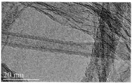
도 1은 카본 섬유(fiber)에 주입된 카본 나노튜브의 예시적인 TEM 이미지를 나타내며;
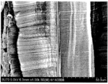
도 2는 카본 나노튜브에 주입된 카본 섬유의 예시적인 SEM 이미지를 나타내며, 여기서 카본 나노튜브는 40㎛ 목적길이의 +20%내이며;
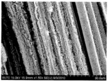
도 3은 카본 나노튜브-주입된 카본 섬유의 직물 무늬(fabric weave)의 예시적인 SEM 이미지를 나타내며; 도 3은 카본 나노튜브-주입된 카본 섬유의 직물 직조(weave)의 예시적인 SEM 이미지를 나타내며;
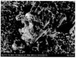
도 4 및 5는 실리콘 카바이드 세라믹 매트릭스에 분포하는 카본 나노튜브-주입된 카본 섬유의 예시적인 SEM 이미지를 나타내며; 그리고
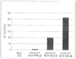
도 6은 카본 나노튜브가 없는 세라믹 매트릭스 복합체에 비하여 하기 실시예에 기술된 예시적인 카본 나노튜브-주입된 카본 섬유 세라믹 매트릭스 복합체의 개선된 열전도도를 보여주는 막대 그래프를 나타낸다. For a more complete understanding of the present disclosure and its advantages, reference is made to the accompanying drawings that show specific implementations of the present disclosure in the detailed description that follows.
1 shows an exemplary TEM image of carbon nanotubes injected into carbon fibers;
2 shows an exemplary SEM image of carbon fibers injected into carbon nanotubes, where the carbon nanotubes are within + 20% of the 40 μm target length;
3 shows an exemplary SEM image of a fabric weave of carbon nanotube-infused carbon fibers; 3 shows an exemplary SEM image of a woven weave of carbon nanotube-infused carbon fibers;
4 and 5 show exemplary SEM images of carbon nanotube-infused carbon fibers distributed in a silicon carbide ceramic matrix; And
FIG. 6 shows a bar graph showing improved thermal conductivity of the exemplary carbon nanotube-infused carbon fiber ceramic matrix composites described in the Examples below as compared to ceramic matrix composites without carbon nanotubes.
본 개시사항의 일부는 세라믹 매트릭스 및 카본 나노튜브-주입된 섬유재료를 포함하는 복합재료에 관한 것이다. 또한, 본 개시사항의 일부는 세라믹 매트릭스 및 카본 나노튜브-주입된 섬유재료를 포함하는 복합재료 및 이러한 복합재료를 포함하는 물품을 제조하는 방법에 관한 것이다.
Part of the disclosure relates to composite materials including ceramic matrices and carbon nanotube-infused fiber materials. In addition, some of the present disclosures relate to composites including ceramic matrices and carbon nanotube-infused fiber materials and methods of making articles comprising such composites.
섬유 재료 및 복합체 매트릭스를 포함하는 복합재료에서, 섬유재료의 향상된 물리적 및/또는 화학적 특성이 복합체 매트릭스(예를들어, 세라믹 매트릭스)에 부여된다. 본 개시사항의 복합재료에서, 이들 강화된 특성은 상기 섬유재료에 주입된 카본 나노튜브에 의해 더욱 증대된다. 상기 카본 나노튜브-주입된 섬유재료는 카본 나노튜브를 복합체 매트릭스에 도입하기 위한 다용도 플랫폼이다. 복합재료에 카본 나노튜브-주입된 섬유재료를 사용하므로써, 복합재료에 카본 나노튜브를 포함시키는 것과 관련된 현저한 문제가 극복되어 진다. 또한, 예를들어, 상기 섬유재료에 주입되는 카본 나노튜브의 길이 및 표면피복(coverage) 밀도를 변화시키므로써, 다른 특성이 복합재료에 선택적으로 부여될 수 있다. 예를들어, 짧은 카본 나노튜브는 복합재료에 대한 구조적인 지지를 부여하도록 사용될 수 있다. 긴 카본 나노튜브는 구조적인 지지를 부여할 뿐만 아니라, 또한, 일반적으로 전도성이 저조하거나 혹은 비-전도성인 복합재료에 전기적으로 전도성인 퍼콜레이션 경로(percolation pathway)를 수립하도록 사용될 수 있다. 더욱이, 복합재료의 다른 영역에서 카본 나노튜브-주입된 섬유재료의 비균일성 및 경사배치(gradient placement)는 원하는 특성을 다른 복합재료 영역에 선택적으로 부여하도록 사용될 수 있다.
In composite materials including fiber materials and composite matrices, improved physical and / or chemical properties of the fiber materials are imparted to the composite matrices (eg, ceramic matrices). In the composite materials of the present disclosure, these enhanced properties are further enhanced by carbon nanotubes injected into the fiber material. The carbon nanotube-infused fiber material is a versatile platform for introducing carbon nanotubes into a composite matrix. By using carbon nanotube-infused fiber materials in the composite material, significant problems associated with the inclusion of carbon nanotubes in the composite material are overcome. Further, for example, by changing the length and surface coverage density of the carbon nanotubes injected into the fiber material, other properties can be selectively imparted to the composite material. For example, short carbon nanotubes can be used to give structural support for the composite material. Long carbon nanotubes not only confer structural support, but can also be used to establish electrically conductive percolation pathways for generally low or non-conductive composites. Moreover, non-uniformity and gradient placement of carbon nanotube-infused fiber materials in other areas of the composite material can be used to selectively impart desired properties to other composite areas.
복합재료, 특히, 시멘트 및 다른 세라믹 매트릭스를 포함하는 복합재료의 적용은 계속하여 확대되어 왔다. 이들 복합재료의 현존하는 그리고 새로운 적용은 현존하는 섬유 보강 기술의 한계를 밀어 제치고 나가가고 있다. 카본 나노튜브가 주입된 섬유 재료를 포함하는 복합재료는 현재의 기술장벽을 극복하고 강화된 구조적 강도 및 부가적인 이로운 이점, 예컨대 예를들어, 전기 전도성 및 열 전도성을 갖는 복합재료를 제공하는 일 방편이다. 복합재료에 대한 전기 전도성 부여의 특히 이로운 결과는 복합재료가 전자파 장해(electromagnetic interference)(EMI) 차폐(전자파 차폐)효과를 제공할 수 있으며, 이는 통상의 섬유재료를 포함하는 비-전도성 복합재료에서는 불가능한 것이다. EMI 차폐성을 갖는 복합재료는 EMI 차폐가 중요한 스텔스 적용 및 다른 환경에 사용될 수 있다. 통상의 복합재료, 특히 세라믹 복합재료에 대한 EMI 차폐적용은 이들이 일반적으로 비-전도성이며, EMI 차폐 효과를 제공하도록 작동할 수 없으므로 종래에 개척되지 않았다. 카본 나노튜브-주입된 섬유재료를 포함하는 복합재료에 대한 많은 다른 적용가능한 적용분야가 있으며, 이러한 복합재료에 구조적인 강화를 제공하는 것이 바람직하다.
The application of composites, particularly composites including cement and other ceramic matrices, has continued to expand. Existing and new applications of these composite materials push the boundaries of existing fiber reinforcement technologies. Composites comprising carbon nanotube-infused fiber materials overcome one of the current technical barriers and provide a composite material with enhanced structural strength and additional beneficial advantages such as, for example, electrical and thermal conductivity. to be. A particularly beneficial result of imparting electrical conductivity to the composites is that the composites can provide electromagnetic interference (EMI) shielding (electromagnetic shielding) effects, which is not the case in non-conductive composites containing conventional fiber materials. It is impossible. Composites with EMI shielding can be used in stealth applications and other environments where EMI shielding is important. EMI shielding applications for conventional composites, in particular ceramic composites, have not been pioneered since they are generally non-conductive and cannot operate to provide EMI shielding effects. There are many other applicable applications for composites including carbon nanotube-infused fiber materials, and it is desirable to provide structural reinforcement to such composites.
본 명세서에서 사용된 바와 같이, 용어 "세라믹 매트릭스"는 카본 나노튜브-주입된 섬유재료를 랜덤 오리엔테이션(random orientations)을 포함하는 특정한 오리엔테이션이 되도록 하는 바이너리(binary), 터셔리(tertiary), 쿼터너리(quaternary) 혹은 이 보다 많은 성분계의 세라믹 재료를 말한다. 세라믹 매트릭스로는 이로써 한정하는 것은 아니지만, 산화물, 탄화물(카바이드), 붕화물(boride) 및 질소화물(nitrides)을 포함한다. 세라믹 매트릭스는 또한, 세라믹 재료를 포함하는 시멘트를 포함할 수 있다. 복합재료에서, 세라믹 매트릭스는 세라믹 매트릭스에 카본 나노튜브-주입된 섬유재료를 가짐으로써 예를들어, 구조적 특성, 전기적 특성 및/또는 열적 특성이 강화(향상)되는 이점을 갖는다.
As used herein, the term "ceramic matrix" refers to a binary, tertiary, quarterary, such that the carbon nanotube-infused fiber material is in a specific orientation, including random orientations. (quaternary) or more constituent ceramic materials. Ceramic matrices include, but are not limited to, oxides, carbides (carbide), borides, and nitrides. The ceramic matrix may also include cement comprising a ceramic material. In composite materials, the ceramic matrix has the advantage that, for example, the carbon nanotube-infused fiber material in the ceramic matrix is enhanced (enhanced) in structural, electrical and / or thermal properties.
본 명세서에서 사용된 바와 같이, 용어 "주입된(infused)"는 결합(bond)됨을 그리고 "주입(infusion)"은 결합(bonding) 공정을 말한다. 이와 같이, 카본 나노튜브-주입된 섬유재료는 섬유재료에 카본 나노튜브가 결합된 섬유재료를 말한다. 섬유재료에 대한 카본 나노튜브의 이러한 결합은 공유결합, 이온결합, 파이-파이 상호작용(pi-pi interactions) 및/또는 반데르 발스 힘-중재된 물리흡착(physisorption)을 포함할 수 있다. 일부 구현에서, 상기 카본 나노튜브는 상기 섬유재료에 직접 결합된다. 다른 구현에서, 상기 카본 나노튜브는 배리어 코팅 및/또는 카본 나노튜브의 성장을 중재하기 위해 사용된 촉매 나노입자에 의해 섬유재료에 간접적으로 결합된다. 카본 나노튜브가 섬유재료에 주입되는 특정한 방식은 결합 모티브(bonding motif)로 칭하여질 수 있다.
As used herein, the term "infused" refers to being bonded and "infusion" refers to the bonding process. As such, the carbon nanotube-infused fiber material refers to a fiber material in which carbon nanotubes are bonded to the fiber material. Such bonding of carbon nanotubes to a fibrous material may include covalent bonds, ionic bonds, pi-pi interactions and / or van der Waals force-mediated physisorption. In some embodiments, the carbon nanotubes are bonded directly to the fibrous material. In another embodiment, the carbon nanotubes are indirectly bound to the fiber material by catalytic nanoparticles used to mediate the growth of barrier coatings and / or carbon nanotubes. The particular way in which carbon nanotubes are injected into the fibrous material can be referred to as a bonding motif.
본 명세서에서 사용된 바와 같이, 용어 "나노입자"는 나노입자의 형태가 구형일 필요는 없지만, 등가구직경(equivalent spherical diameter)이 약 0.1nm 내지 100nm의 직경인 입자를 말한다.
As used herein, the term "nanoparticle" refers to a particle whose equivalent spherical diameter is about 0.1 nm to 100 nm, although the shape of the nanoparticle need not be spherical.
본 명세서에서 사용된 바와 같이, 용어 "패시베이션층(passivation layer)"은 섬유재료 및/또는 그 위해 주입되는 카본 나노튜브의 반응을 방지 혹은 실질적으로 억제하는 카본 나노튜브-주입된 섬유재료의 적어도 일부에 디포지트되는 층을 말한다. 패시베이션층은 예를들어, 고온과 접하게 되는 경우에 복합재료의 형성 도중에 반응을 방지 혹은 실질적으로 억제하기에 이로울 수 있다. 나아가, 패시베이션층은 복합재료의 형성 전에 또는 후에, 대기 성분과의 반응을 방지 혹은 실질적으로 억제할 수 있다. 패시베이션층의 예시적인 재료로는 예를들어, 전기도금(electroplated) 니켈, 크롬, 마그네슘, 티타늄, 은, 주석 또는 티타늄 디보라이드(티타늄 diboride)를 포함할 수 있다.
As used herein, the term "passivation layer" refers to at least a portion of a carbon nanotube-infused fiber material that prevents or substantially inhibits the reaction of the fiber material and / or the carbon nanotubes injected therefor. Refers to the layer being deposited on. The passivation layer may be advantageous to prevent or substantially inhibit the reaction during the formation of the composite, for example when in contact with high temperatures. Furthermore, the passivation layer can prevent or substantially inhibit the reaction with the atmospheric components before or after the formation of the composite material. Exemplary materials of the passivation layer may include, for example, electroplated nickel, chromium, magnesium, titanium, silver, tin or titanium diboride.
본 명세서에서 사용된 바와 같이, 용어 "사이징제(sizing agent)" 혹은 "사이징(sizing)"은 섬유재료의 완전한 상태(integrity)를 보호하고, 복합재에서 섬유재료와 세라믹 매트릭스 사이의 향상된 계면 상호작용을 제공하고, 및/또는 섬유재료의 특정한 물리적 특성을 향상시키도록 섬유재료의 제조에 코팅으로서 사용되는 재료를 집합적으로 칭한다.
As used herein, the term "sizing agent" or "sizing" protects the integrity of the fibrous material and improves the interfacial interaction between the fibrous material and the ceramic matrix in the composite. And collectively referred to as materials used as coatings in the manufacture of the fibrous material to provide and / or enhance certain physical properties of the fibrous material.
본 명세서에서 사용된 바와 같이, 용어 "스풀가능한 치수(spoolable dimension)"는 길이에 한정되지 않는 적어도 일 치수(dimension)를 가지는 섬유 재료를 말하며, 이후에 카본 나노튜브가 주입되는 섬유 재료가 스풀(spool) 또는 맨드릴에 저장될 수 있게 한다. "스풀가능한 치수"의 섬유재료는 적어도 일 치수(one dimension)를 가지며, 이는 섬유재료에 카본 나노튜브를 주입하는 배치 혹은 연속 공정에 대한 사용을 나타낸다.
As used herein, the term "spoolable dimension" refers to a fiber material having at least one dimension, not limited to length, after which the fiber material into which the carbon nanotubes are implanted is spooled ( to be stored in a spool or mandrel. Fibrous materials of "spoolable dimensions" have at least one dimension, indicating the use of a batch or continuous process of injecting carbon nanotubes into the fibrous material.
본 명세서에서 사용된 바와 같이, 용어 "전이 금속"은 주기율표의 d-블록의 어떠한 원소 혹은 원소의 합금(3그룹 내지 12그룹)을 말하며, "전이 금속염"은 어떠한 전이금속 화합물, 예컨대 예를들어, 전이금속 산화물, 탄화물, 질화물 등을 말한다. 예시적인 전이금속 촉매 나노입자로는 예를들어, Ni, Fe, Co, Mo, Cu, Pt, Au, Ag, 이들의 합금, 이들의 염 및 이들의 혼합물을 포함한다.
As used herein, the term “transition metal” refers to any element or alloy of elements (groups 3 to 12) of the d-block of the periodic table, and “transition metal salts” refers to any transition metal compound, such as , Transition metal oxide, carbide, nitride and the like. Exemplary transition metal catalyst nanoparticles include, for example, Ni, Fe, Co, Mo, Cu, Pt, Au, Ag, alloys thereof, salts thereof, and mixtures thereof.
본 명세서에서 사용된 바와 같이, "균일한 길이"는 카본 나노튜브가 길이 약 1㎛ 내지 약 500㎛ 범위의 카본 나노튜브 길이에 대하여, 총 카본 나노튜브 길이의 플러스 혹은 마이너스 약 20% 이하의 허용 오차(tolerance)의 길이를 갖는 상태를 말한다. 매우 짧은 카본 나노튜브 길이에서(예를들어, 약 1㎛ 내지 약 4㎛), 상기 허용 오차는 플러스 혹은 마이너스 약 1㎛일 수 있다. 즉, 총 카본 나노튜브 길이의 약 20%를 초과할 수 있다.
As used herein, “uniform length” means that the carbon nanotubes have a plus or minus of about 20% or less of the total carbon nanotube length, for carbon nanotube lengths ranging from about 1 μm to about 500 μm in length. It refers to a state having a length of tolerance. At very short carbon nanotube lengths (eg, about 1 μm to about 4 μm), the tolerance can be plus or minus about 1 μm. That is, greater than about 20% of the total carbon nanotube length.
본 명세서에서 사용된 바와 같이, "균일한 밀도분포"는 섬유재료에 대한 카본 나노튜브 밀도가 카본 나노튜브로 피복되는 섬유재료 표면적에 대하여 플러스 혹은 마이너스 약 10%의 피복율(coverage)의 허용오차를 갖는 상태를 말한다.
As used herein, "uniform density distribution" means a tolerance of plus or minus about 10% coverage of the fiber material surface area where the carbon nanotube density for the fiber material is coated with the carbon nanotubes. Say that you have a state.
다양한 구현에서, 세라믹 매트릭스 및 카본 나노튜브-주입된 섬유재료를 포함하는 복합재료가 본 명세서에 기술된다.
In various implementations, composite materials are described herein, including ceramic matrices and carbon nanotube-infused fiber materials.
카본 화아버, 세라믹 화이버, 메탈 화이버 및 글라스 화이버를 포함하는 카본 나노튜브가 주입되는 섬유재료는 출원인의 동시 게류 중인, 모두 2009.11.2일자로 출원된 미국특허출원 12/611,073, 12/611,101 및 12/611,103에 기술된 것이며, 이들 출원문헌은 본 명세서에 참고로 포함된다. 도 1은 카본 화이버(fiber)에 주입된 카본 나노튜브의 예시적인 TEM 이미지를 나타낸다. 도 2는 카본 나노튜브에 주입된 카본 화이버의 예시적인 SEM 이미지를 나타내며, 여기서 카본 나노튜브는 40㎛ 목적길이의 +20% 범위 이내이다. 도 1 및 도 2의 이미지에서, 카본 나노튜브는 다중-벽(multi-wall) 카본 나노튜브이지만, 단일-벽 카본 나노튜브, 이중-벽 카본 나노튜브 및 둘 보다 많은 벽을 갖는 다중-벽 카본 나노튜브와 같은 카본 나노튜브가 복합재료의 섬유 재료에 주입되도록 사용될 수 있다.
Fibrous materials into which carbon nanotubes, including carbon fibers, ceramic fibers, metal fibers and glass fibers are injected, are all pending US patent applications 12 / 611,073, 12 / 611,101 and 12, filed on January 12, 2009 / 611,103, which are incorporated herein by reference. 1 shows an exemplary TEM image of carbon nanotubes implanted in carbon fiber. 2 shows an exemplary SEM image of carbon fibers implanted in carbon nanotubes, where the carbon nanotubes are within + 20% of the 40 μm target length. In the images of FIGS. 1 and 2, the carbon nanotubes are multi-wall carbon nanotubes, but multi-wall carbon with single-wall carbon nanotubes, double-wall carbon nanotubes and more than two walls. Carbon nanotubes, such as nanotubes, can be used to inject into the fiber material of the composite material.
상기한 섬유재료는 단지 카본 나노튜브가 주입되어 복합재료에 포함될 수 있는 다양한 섬유 재료의 예시이다. 본 명세서에 기술된 다양한 구현중 어떠한 구현에서, 카본 나노튜브가 주입될 수 있는 섬유재료로는 예를들어, 글라스 화이버, 카본 화이버, 금속 화이버, 세라믹 화이버 및 유기 화이버 (예를들어, 아라미드 화이버)를 포함한다. 일부 구현에서, 상기 섬유재료로는 예를들어, 글라스 화이버, 카본 화이버, 금속 화이버, 세라믹 화이버, 유기 화이버, 실리콘 카바이드(SiC) 화이버, 보론 카바이드(B4C) 화이버, 실리콘 니트라이드(Si3N4) 화이버, 알루미늄 옥사이드(A1203) 화이버 및 이들의 다양한 조합을 포함한다. 일부 구현에서, 카본 나노튜브의 바람직한 특성이 카본 나노튜브가 주입되는 섬유재료에 부여되며, 이에 따라, 결과물인 복합재료의 세라믹 매트릭스가 강화된다. 이 기술분야의 숙련된 자는 카본 나노튜브가 주입될 수 있는 어떠한 타입의 섬유재료가 원하는 목적의 특성을 강화시키기 위해서 본 명세서에 기술된 구현에 또한 사용될 수 있음을 이해할 것이다. 나아가, 섬유 재료의 고유성(identity) 및/또는 일부(fraction) 및/또는 섬유재료에 주입되는 카본 나노튜브의 양을 다르게 하므로써, 다른 특성이 복합재료에 부여될 수 있다. 이론이나 메카니즘에 근거한 것은 아니지만, 출원인은 섬유재료가 복합재료의 세라믹 매트릭스를 구조적으로 보강하는 것으로 생각한다.
The above fiber materials are merely examples of various fiber materials that can be incorporated into the composite material by injecting carbon nanotubes. In any of the various implementations described herein, fiber materials into which carbon nanotubes can be implanted include, for example, glass fibers, carbon fibers, metal fibers, ceramic fibers, and organic fibers (eg, aramid fibers). It includes. In some embodiments, the fiber material is, for example, glass fibers, carbon fibers, metal fibers, ceramic fibers, organic fibers, silicon carbide (SiC) fibers, boron carbide (B 4 C) fibers, silicon nitride (Si 3 N 4 ) fibers, aluminum oxide (A1 2 0 3 ) fibers, and various combinations thereof. In some embodiments, desirable properties of the carbon nanotubes are imparted to the fiber material into which the carbon nanotubes are implanted, thereby strengthening the ceramic matrix of the resulting composite material. One skilled in the art will understand that any type of fibrous material into which carbon nanotubes can be implanted can also be used in the implementations described herein to enhance the desired purpose properties. Further, different properties can be imparted to the composite by varying the identity and / or fraction of the fiber material and / or the amount of carbon nanotubes injected into the fiber material. Although not based on theory or mechanism, Applicants believe that the fiber material structurally reinforces the ceramic matrix of the composite material.
일부 구현에서, 카본 나노튜브-주입된 섬유재료는 카본 나노튜브가 없는 섬유재료를 갖는 복합재료에 포함될 수 있다. 예시적인 조합으로는 이로써 제한하는 것은 아니지만, 카본 나노튜브-주입된 글라스 화이버와 카본 나노튜브의 주입이 없는 세라믹 화이버, 카본 나노튜브-주입된 세라믹 화이버와 카본 나노튜브의 주입이 없는 글라스 화이버, 카본 나노튜브-주입된 카본 화이버와 카본 나노튜브의 주입이 없는 세라믹 화이버, 및 카본 나노튜브-주입된 카본 화이버와 카본 나노튜브의 주입이 없는 글라스 화이버를 포함한다. 또한, 어떠한 타입의 카본 나노튜브-주입된 섬유가 카본 나노튜브의 주입이 없는 동일한 타입의 섬유재료를 갖는 복합재료에 포함될 수 있다.
In some embodiments, the carbon nanotube-infused fiber material can be included in a composite material having a fiber material free of carbon nanotubes. Exemplary combinations include, but are not limited to, carbon nanotube-infused glass fibers and ceramic fibers without carbon nanotube injection, carbon nanotube-infused ceramic fibers and glass fibers without carbon nanotube injection, carbon Nanotube-infused carbon fibers and ceramic fibers without injection of carbon nanotubes, and glass fiber without injection of carbon nanotube-infused carbon fibers and carbon nanotubes. In addition, any type of carbon nanotube-infused fiber may be included in a composite material having the same type of fiber material without the injection of carbon nanotubes.
섬유 제조에 사용되는 전구체에 따라 분류되는 3가지 타입의 카본 화이버가 존재하며, 이중 어떠한 것이 본 명세서에 기술된 다양한 구현에 사용될 수 있다: 레이온, 폴리아크릴로니트릴(PAN) 및 피치. 셀룰로즈 재료인 레이온 전구체로 된 카본 화이버는 약 20%로 상대적으로 낮은 탄소 함량을 가지며, 섬유(화이버)는 낮은 강도(strength) 및 강성도(stiffness)를 갖는 경향이 있다. 이에 반하여, 폴리아크릴로니트릴(PAN)은 약 55%의 탄소 함량을 갖는 카본 화이버를 제공하며 최소한의 표면 결함으로 인하여 뛰어난 인장 강도(tensile strength)를 갖는다. 석유(petroleum) 아스팔트, 코올 타르 및 폴리비닐 클로라이드에 기초한 피치 전구체가 또한 카본 화이버의 제조에 사용될 수 있다. 피치는 비교적 저가이며 고탄소 수득률을 나타내지만, 결과물인 카본 화이버의 주어진 배치에서 비-균일성이 문제될 수 있다.
There are three types of carbon fibers classified according to the precursors used to make the fiber, any of which may be used in the various implementations described herein: rayon, polyacrylonitrile (PAN) and pitch. Carbon fibers made of rayon precursor, a cellulose material, have a relatively low carbon content of about 20%, and fibers (fibers) tend to have low strength and stiffness. In contrast, polyacrylonitrile (PAN) provides carbon fibers with a carbon content of about 55% and has excellent tensile strength due to minimal surface defects. Pitch precursors based on petroleum asphalt, coal tar and polyvinyl chloride may also be used in the production of carbon fibers. Pitch is relatively inexpensive and shows high carbon yield, but non-uniformity may be a problem in a given batch of the resulting carbon fibers.
다양한 구현에서, 본 발명에 의한 복합재료의 섬유재료는 필라멘트, 야안(yarn), 화이버 토우, 테이프, 화이버-브레이드(fiber-braid), 직물, 부직물, 화이버 플라이 및 다른 3차원의 직조 구조물(woven structures) 또는 부직 구조물(non-woven structures)일 수 있다. 예를들어, 섬유 재료가 카본 화이버인 구현에서, 상기 섬유 재료는 비-제한적인 형태로 카본 필라멘트, 카본 화이버 야안, 카본 화이버 토우, 카본 테이프, 카본 화이버-브레이드, 직조 카본 화이버, 부직 카본 화이버 매트, 카본 화이버 플라이 및 다른 3차원의 직조 혹은 부직 구조물일 수 있다. 도 3은 카본 나노튜브-주입된 카본 화이버의 직물 무늬(fabric weave)의 예시적인 SEM 이미지를 나타낸다. 다양한 구현에서, 균일한 길이 및 분포(distribution)의 카본 나노튜브가 필라멘트, 화이버 토우, 테이프, 직물 및 다른 3차원의 제직 구조물의 스플러블 길이를 따라 제조될 수 있다. 다양한 필라멘트, 화이버 토우, 야안, 매트, 직물 및 부직물 등에 카본 나노튜브가 직접 주입될 수 있으나, 카본 나노튜브-주입된 섬유로 부터의 모 화이버 토우(parent fiber tow), 야얀 등으로 부터 더 높은 차수의 구조물(higher ordered structures)을 제조할 수 있다. 예를들어, 카본 나노튜브-주입된 섬유 재료가 카본 나노튜브-주입된 화이버 토우로 부터의 직물로 변형될 수 있다.
In various embodiments, the fibrous material of the composite material according to the present invention may comprise filaments, yarns, fiber tows, tapes, fiber-braids, fabrics, nonwovens, fiber plies, and other three-dimensional woven structures ( woven structures or non-woven structures. For example, in an embodiment where the fiber material is carbon fiber, the fiber material is in non-limiting form carbon filament, carbon fiber yarn, carbon fiber toe, carbon tape, carbon fiber-braid, woven carbon fiber, nonwoven carbon fiber mat , Carbon fiber ply and other three-dimensional woven or nonwoven structures. 3 shows an exemplary SEM image of the fabric weave of carbon nanotube-infused carbon fibers. In various implementations, carbon nanotubes of uniform length and distribution can be made along the sable lengths of filaments, fiber tows, tapes, fabrics, and other three-dimensional woven structures. Carbon nanotubes can be directly injected into various filaments, fiber tows, yarns, mats, fabrics and nonwovens, but higher from fiber tows, carbon yarns, etc. Higher ordered structures can be fabricated. For example, the carbon nanotube-infused fiber material can be transformed into a fabric from carbon nanotube-infused fiber tow.
필라멘트는 일반적으로 약 1㎛ 내지 약 100㎛ 크기 범위의 직경을 갖는 높은 종횡비(aspect ratio) 섬유를 포함한다.
Filaments generally comprise high aspect ratio fibers having diameters ranging from about 1 μm to about 100 μm in size.
일부 구현에서, 화이버 토우는 일반적으로 조밀하게 연계된 카본 필라멘트 번들이며, 이는 서로 트위스트되어(twist) 야안으로 될 수 있다. 야안은 가까이 연계된 트위스트된 필라멘트의 번들이며, 이때, 야안에서 각각의 필라멘트의 직경은 비교적 균일하다. 야안은 '텍스(tex)' (1000 직선 미터 당의 그람(gram) 중량으로 표현됨) 혹은 '데니어(denier)' (10,000 야드 당의 파운드 중량으로 표현됨)로 기술되는 가변적인 중량을 갖는다. 야안에 대하여, 전형적인 텍스 범위는 일반적으로 약 200 내지 약 2000이다.
In some implementations, the fiber tow is generally a tightly linked carbon filament bundle, which can be twisted into each other and into the eye. The yarns are bundles of twisted filaments closely linked, wherein the diameter of each filament in the yarns is relatively uniform. The yarns have a variable weight, described as 'tex' (expressed in gram weight per 1000 linear meters) or 'denier' (expressed in pounds per 10,000 yards). For the eye, a typical tex range is generally about 200 to about 2000.
화이버 블레이드는 고밀하게 채워진(packed) 섬유의 로프-형 구조물(rope-like structrues)을 나타낸다. 이러한 로프-형 구조물은 예를들어, 야안으로 부터 어셈블될 수 있다. 블레이드 구조물은 공동부(hollow portion)을 포함할 수 있다. 또한, 블레이드 구조물은 대략 다른 코어 재료와 어셈블될 수 있다.
Fiber blades represent rope-like structrues of tightly packed fibers. Such rope-like structures can be assembled, for example, from the eye. The blade structure may comprise a hollow portion. In addition, the blade structure may be assembled with approximately another core material.
화이버 토우는 느슨하게 연관된(연계된) 트위스트되지 않은 필라멘트의 번들을 포함한다. 야안에서와 같이, 화이버 토우에서 필라멘트의 직경은 일반적으로 균일하다. 화이버 토우는 또한, 다양한 중량 및 일반적으로 약 200 내지 2000 범위인 텍스 범위를 갖는다. 또한, 화이버 토우는 예컨대, 예를들어, 12K 토우, 24K 토우, 48K 토우 등과 같은 화이버 토우의 필라멘트의 천(1000)의 수로 종종 특징이 지워진다.
The fiber tow comprises a bundle of loosely associated (associated) untwisted filaments. As in the field of view, the diameter of the filaments in the fiber tow is generally uniform. Fiber tows also have varying weights and tex ranges that generally range from about 200 to 2000. In addition, fiber tows are often characterized by the number of fabrics 1000 of filaments of fiber tow, for example, 12K tow, 24K tow, 48K tow, and the like.
테이프(tapes)는 예를들어, 제직(직조, weave) 혹은 부직 패턴화된 화이버 토우로 어셈블될 수 있는 섬유 재료이다. 테이프는 폭이 달라질 수 있으며, 일반적으로, 리본과 유사한 2면 구조이다. 본 명세서에 기술된 다양한 구현에서, 카본 나노튜브는 테이프의 일면 도는 양면에서 테이프의 섬유재료에 주입될 수 있다. 또한, 다른 타입, 직경 혹은 길이의 카본 나노튜브가 테이프의 각각의 면에서 성장될 수 있다. 섬유 재료에 주입된 카본 나노튜브가 다른 타입, 직경 혹은 길이를 갖는 이점은 후술된다. 출원인의 동시-게류 중인 미국특허 출원에 기술되어 있는 바와 같이, 테이프 스풀에 대한 카본나노 튜브의 주입은 연속적인 방식으로 행하여질 수 있다.
Tapes are, for example, fibrous materials that can be assembled into woven (weave) or nonwoven patterned fiber tows. The tape can vary in width and is generally a two sided structure similar to a ribbon. In various implementations described herein, carbon nanotubes may be injected into the fiber material of the tape on one or both sides of the tape. In addition, carbon nanotubes of different types, diameters or lengths may be grown on each side of the tape. The advantages that the carbon nanotubes injected into the fiber material have different types, diameters or lengths are described below. As described in Applicant's co-pending US patent application, the injection of carbon nanotubes into the tape spool can be done in a continuous manner.
일부 구현에서, 섬유 재료는 직물형(fabric-like) 혹은 시트-형(sheet-like) 구조물로 준비될 수 있다. 이로는 상기한 테이프 뿐만 아니라 예를들어, 직물 매트, 부직물 매트 및 섬유 플라이를 포함한다. 이러한, 높은 차수의 구조물(higher ordered structures)는 이미 카본 나노튜브가 섬유 재료에 주입된 모 화이버 토우(parent fiber tows), 야안, 필라멘트 등으로 부터 어셀블될 수 있다. 테이프에서와 같이, 이러한 구조물은 여기에 카본 나노튜브가 연속 주입되는 기재로 또한 사용될 수 있다.
In some implementations, the fibrous material may be prepared in a fabric-like or sheet-like structure. These include, for example, the above mentioned tapes as well as woven mats, nonwoven mats and fiber plies. Such higher ordered structures may be associable from parent fiber tows, yarns, filaments, etc., in which carbon nanotubes have already been implanted into the fiber material. As with tape, this structure can also be used as a substrate into which carbon nanotubes are continuously implanted.
출원인의 동시-게류 중인 미국특허 출원에 기술되어 있는 바와 같이, 섬유 재료는 여기에 카본 나노튜브를 성장시키기 위한 목적으로 섬유재료상에 촉매 나노입자 층(전형적으로 단지 단일층임)을 제공하도록 개질된다. 다양한 구현에서, 카본 나노튜브의 성장을 중재하는데 사용되는 촉매 나노입자는 전이금속 및 이들의 다양한 염이다.
As described in Applicant's co-pending US patent application, the fiber material is modified to provide a layer of catalyst nanoparticles (typically only a single layer) on the fiber material for the purpose of growing carbon nanotubes thereto. In various embodiments, the catalytic nanoparticles used to mediate the growth of carbon nanotubes are transition metals and their various salts.
일부 구현에서, 상기 섬유재료는 배리어 코팅을 추가로 포함한다. 예시적인 배리어 코팅으로는 예를들어, 알콕시실란, 메틸실록산, 알룸옥산(alumoxanes), 알루미나 나노입자, 스핀 온글라스(spin on glass) 및 글라스 나노입자를 추가로 포함한다. 예를들어, 일 구현에서, 배리어 코팅은 Accuglass T-11 Spin-On Glass(Honeywell International Inc., Morristown, NJ)이다. 일부 구현에서, 카본 나노튜브 합성용 촉매 나노입자는 경화되지 않은 배리어 코팅재료와 합하여지져 섬유 재료에 함께 적용될 수 있다. 다른 구현에서, 배리어 코팅 재료는 촉매 나노입자의 디포지션 전에 섬유재료에 첨가될 수 있다. 일반적으로, 배리어 코팅은 촉매 나노입자가 카본 나노튜브 성장용 카본 공급원료 가스에 노출되도록 충분히 얇다. 일부 구현에서, 배리어 코팅의 두께는 촉매 나노입자의 유효 직경(effective diameter) 보다 작거나 혹은 대략 동일하다. 일부 구현에서, 배리어 코팅의 두께는 약 10nm 내지 약 100nm 범위이다. 다른 구현에서, 배리어 코팅의 두께는 약 10nm 내지 약 50nm 범위이며, 40nm를 포함한다. 일부 구현에서, 배리어 코팅의 두께는 약 10nm 미만이며, 약 1nm, 약 2 nm, 약 3 nm, 약 4 nm, 약 5 nm, 약 6 nm, 약 7 nm, 약 8 nm, 약 9 nm, 및 약 10 nm를 포함하며, 모든 값 및 이들 사이의 모든 하위 범위를 포함한다.
In some embodiments, the fibrous material further comprises a barrier coating. Exemplary barrier coatings further include, for example, alkoxysilanes, methylsiloxanes, alumoxanes, alumina nanoparticles, spin on glass and glass nanoparticles. For example, in one implementation, the barrier coating is Accuglass T-11 Spin-On Glass (Honeywell International Inc., Morristown, NJ). In some embodiments, catalyst nanoparticles for carbon nanotube synthesis can be combined with an uncured barrier coating material and applied together to a fiber material. In another embodiment, the barrier coating material may be added to the fiber material prior to deposition of the catalyst nanoparticles. Generally, the barrier coating is thin enough to expose the catalyst nanoparticles to the carbon feedstock gas for carbon nanotube growth. In some embodiments, the thickness of the barrier coating is less than or approximately equal to the effective diameter of the catalyst nanoparticles. In some embodiments, the barrier coating has a thickness in the range of about 10 nm to about 100 nm. In another implementation, the thickness of the barrier coating ranges from about 10 nm to about 50 nm and includes 40 nm. In some embodiments, the thickness of the barrier coating is less than about 10 nm, about 1 nm, about 2 nm, about 3 nm, about 4 nm, about 5 nm, about 6 nm, about 7 nm, about 8 nm, about 9 nm, and About 10 nm, including all values and all subranges therebetween.
이론에 근거한 것은 아니지만, 배리어 코팅은 섬유재료와 카본 나노튜브 사이의 중간층으로 작용할 수 있으며, 상기 카본 나노튜브를 섬유재료에 기계적으로 주입한다. 이러한 기계적 주입은 강건한 시스템을 제공하며, 이러한 시스템에서 섬유 재료는 카본 나노튜브를 체계화(정리)하는 플랫폼으로 작용하며, 카본 나노튜브의 이로운 특성이 섬유 재료에 부여되도록 한다. 더욱이, 배리어 코팅을 포함하는 이점은 카본 나노튜브의 성장을 촉진하기 위해 사용되는 상승된 온도에서의 열 손상 및/또는 수분 노출에 기인한 화학적 손상으로 부터 섬유재료의 보호를 포함한다. 일부 구현에서, 배리어 코팅은 카본 나노튜브-주입된 섬유재료가 복합재료에 포함되기 전에 제거된다. 그러나, 다른 구현에서, 복합재료는 배리어 코팅이 온전하게 있는 카본 나노튜브-주입된 섬유재료를 포함할 수 있다.
Although not based on theory, the barrier coating can act as an intermediate layer between the fiber material and the carbon nanotubes, and mechanically inject the carbon nanotubes into the fiber material. This mechanical injection provides a robust system in which the fiber material acts as a platform for organizing (cleaning up) carbon nanotubes, allowing the beneficial properties of the carbon nanotubes to be imparted to the fiber material. Moreover, the advantages of including a barrier coating include the protection of the fibrous material from chemical damage due to thermal damage and / or moisture exposure at elevated temperatures used to promote the growth of carbon nanotubes. In some embodiments, the barrier coating is removed before the carbon nanotube-infused fiber material is included in the composite material. However, in other implementations, the composite material may comprise carbon nanotube-infused fiber materials with the barrier coating intact.
촉매 나노입자의 디포지션 후에, 일부 구현에서 섬유재료에 카본 나노튜브를 연속적으로 성장시키기 위해서 화학 증기 증착(chemical vapor deposition, CVD)-베이스 공정이 사용된다. 상기 결과물인 카본 나노튜브-주입된 섬유재료 자체가 복합 건축물이다. 보다 일반적으로, 카본 나노튜브는 이 기술분아의 기술자에게 알려져 있는 어떠한 기술을 사용하여 섬유재료에 주입될 수 있다. 카본 나노튜브 합성의 예시적인 기술로는 예를들어, 마이크로 공동(micro-cavity), 열 혹은 플라즈마 CVD(plasma-enhanced CVD) 기술, 레이져 어블레이션(laser ablation), 아크 방전 및 고압 카본 모녹사이드(HiPCO) 합성을 포함한다. 일부 구현에서, 상기 CVD 성장은 성장 공정 도중에 카본 나노튜브가 전기장의 방향을 따르도록 전기장을 제공하여 플라즈마-증강된(plasma-enhanced)로 행하여질 수 있다.
After deposition of catalytic nanoparticles, in some embodiments a chemical vapor deposition (CVD) -based process is used to continuously grow carbon nanotubes in the fiber material. The resulting carbon nanotube-infused fiber material itself is a composite building. More generally, carbon nanotubes can be injected into the fiber material using any technique known to those skilled in the art. Exemplary techniques for carbon nanotube synthesis include, for example, micro-cavity, thermal or plasma-enhanced CVD (laser ablation), laser ablation, arc discharge and high pressure carbon monoxide ( HiPCO) synthesis. In some embodiments, the CVD growth can be done plasma-enhanced by providing an electric field such that carbon nanotubes follow the direction of the electric field during the growth process.
본 발명에 의한 복합체의 섬유재료에 주입되는 카본 나노튜브의 타입은 제한없이 일반적으로 다양할 수 있다. 본 명세서의 다양한 구현에서, 섬유재료에 주입된 카본 나노튜브는 예를들어, 단일 벽 카본 나노튜브(SWNTs), 이중 벽 카본 나노튜브(DWNTs), 다중벽 카본 나노튜브(MWNTs) 및 이들의 어떠한 조합을 포함하는 풀러린류의 어떠한 다수의 탄소의 실린더형 동소체일 수 있다. 일부 구현에서, 카본 나노튜브는 풀러린 같은(fullerene-like) 구조로 캡핑될 수 있다. 달리 말하면, 카본 나노튜브는 이러한 구현에서 말단이 폐쇄될 수 있다. 그러나, 다른 구현에서, 카본 나노튜브는 말단이 개방된 상태를 유지할 수 있다. 일부 구현에서, 카본 나노튜브는 다른 물질들을 둘러쌀 수 있다. 일부 구현에서, 카본 나노튜브 섬유재료에 주입된 후에 공유결합으로 작용화된다. 작용화(functionalization)는 카본 나노튜브와 특정한 세라믹 매트릭스의 혼화성(compatibility)를 증가시키도록 사용될 수 있다. 일부 구현에서, 플라즈마 공정이 카본 나노튜브의 작용화를 촉진시키는데 사용된다.
The type of carbon nanotubes injected into the fiber material of the composite according to the present invention may generally vary without limitation. In various implementations of the present disclosure, carbon nanotubes implanted into a fibrous material include, for example, single wall carbon nanotubes (SWNTs), double wall carbon nanotubes (DWNTs), multiwall carbon nanotubes (MWNTs) and any of these. It can be any number of carbon cylindrical allotropes of the fullerenes, including combinations. In some embodiments, carbon nanotubes can be capped into a fullerene-like structure. In other words, the carbon nanotubes may be closed end in this embodiment. However, in other embodiments, the carbon nanotubes may remain open at their ends. In some implementations, carbon nanotubes can surround other materials. In some embodiments, they are covalently functionalized after being injected into the carbon nanotube fiber material. Functionalization can be used to increase the compatibility of carbon nanotubes with certain ceramic matrices. In some embodiments, a plasma process is used to promote the functionalization of carbon nanotubes.
일부 구현에서, 섬유재료에 주입되는 카본 나노튜브는 섬유재료의 세로축에 대하여 실질적으로 수직이다. 달리 말하면, 섬유재료에 주입되는 카본 나노튜브는 섬유 표면에 대하여 원주에서 수직이다. 다른 구현에서, 섬유재료에 주입되는 카본 나노튜브는 섬유재료의 세로축에 대하여 실질적으로 평행하다.
In some embodiments, the carbon nanotubes injected into the fibrous material are substantially perpendicular to the longitudinal axis of the fibrous material. In other words, the carbon nanotubes injected into the fiber material are perpendicular to the circumference with respect to the fiber surface. In another embodiment, the carbon nanotubes injected into the fibrous material are substantially parallel to the longitudinal axis of the fibrous material.
일부 구현에서, 섬유재료에 주입되는 카본 나노튜브는 번들(bundle)이 아니므로, 섬유재료와 카본 나노튜브 사이의 강한 결합이 가능하게 된다. 번들이 아닌 카본 나노튜브는 이로운 카본 나노튜브의 특성이 본 발명에 의한 복합재료에 발현되도록 한다. 다른 구현에서, 섬유재료에 주입되는 카본 나노튜브는 카본 나노튜브 합성 도중에 성장 밀도를 감소시키므로써 매우 균일하고, 얽어매인(entangled) 카본 나노튜브 형태로 제조될 수 있다. 이러한 구현에서, 상기 카본 나노튜브는 섬유재료의 세로축에 대하여 카본 나노튜브가 실질적으로 수직으로 배열되기에 충분한 밀도로 성장하지 않는다.
In some embodiments, the carbon nanotubes injected into the fibrous material are not bundles, thus enabling strong bonding between the fibrous material and the carbon nanotubes. Non-bundle carbon nanotubes allow the properties of the beneficial carbon nanotubes to be expressed in the composite material according to the present invention. In another embodiment, the carbon nanotubes injected into the fibrous material can be made in the form of highly uniform, entangled carbon nanotubes by reducing the growth density during carbon nanotube synthesis. In this embodiment, the carbon nanotubes do not grow to a density sufficient to arrange the carbon nanotubes substantially perpendicular to the longitudinal axis of the fibrous material.
일부 구현에서, 섬유재료에 주입되는 카본 나노튜브의 양은 세라믹 매트릭스 혹은 섬유재료 단독에 비하여 복합재료의 적어도 하나의 특성이 강화되도록 선택된다. 이러한 특성으로는 예를들어, 인장강도, 영률(young's modulus), 전단 강도, 전단 모듈러스, 인성(toughness), 압축강도, 압축 모듈러스, 밀도, 전자파 흡수율/반사율, 음향 투과율, 전기 전도도 및 열 전도도를 포함할 수 있다. 복합재료에서 카본 나노튜브의 존재는 또한, 카본 나노튜브가 없는 비교대상이 되는 복합재료에 비하여 더 큰 중량 대비 강도 비율을 갖는 더 가벼운 최종 복합재료를 제공한다.
In some embodiments, the amount of carbon nanotubes injected into the fiber material is selected such that at least one property of the composite material is enhanced as compared to the ceramic matrix or the fiber material alone. These properties include, for example, tensile strength, young's modulus, shear strength, shear modulus, toughness, compressive strength, compression modulus, density, electromagnetic wave absorption / reflectance, acoustic transmittance, electrical conductivity and thermal conductivity. It may include. The presence of carbon nanotubes in the composite also provides a lighter final composite with a greater weight to strength ratio than comparable composites without carbon nanotubes.
일부 구현에서, 섬유 재료에는 섬유재료의 원하는 특성 및 이에 따른 복합재료가 얻어지도록 특정한 타입의 카본 나노튜브가 주입될 수 있다. 예를들어, 복합재료의 전기적 특성은 다양한 타입, 키랄성(chiralities), 직경, 길이 및 밀도의 카본 나노튜브를 섬유 재료에 주입하므로써 개질될 수 있다.
In some implementations, the fiber material may be implanted with certain types of carbon nanotubes to obtain the desired properties of the fiber material and thus the composite material. For example, the electrical properties of the composite can be modified by injecting carbon nanotubes of various types, chiralities, diameters, lengths and densities into the fiber material.
전기 전도도 또는 도전율은 전류를 전도할 수 있는 물질의 능력에 대한 측정이다. 카본 나노튜브는 이들의 키랄성에 따라 금속, 세미금속(semimetallic) 또는 반도체일 수 있다. 카본 나노튜브의 키랄성(chirality)에 대한 알려진 명명법 시스템이 이 기술분야의 숙련된 자에게 알려져 있으며, 카본 나노튜브는 더블 인덱스(double index)(n,m)에 의해 서로 구별되며, 여기서, n 및 m은 정수로서, 관형 구조물로 형성되는 경우에, 육방정계 그라파이트의 절단(cut) 및 포장(wrapping)을 설명한다. 예를들어, m=n인 경우에, 카본 나노튜브는 '암-체어(arm-chair)' 타입이다. 이러한 암-체어 카본 나노튜브, 특히 단일벽 카본 나노튜브는 금속성 전도체이며, 매우 높은 전기 전도도 및 열 전도도를 갖는다. 또한, 이러한 단일벽 카본 나노튜브는 매우 높은 인장 강도를 갖는다.
Electrical conductivity or conductivity is a measure of the ability of a material to conduct current. Carbon nanotubes may be metal, semimetallic or semiconductor depending on their chirality. Known nomenclature systems for the chirality of carbon nanotubes are known to those skilled in the art, and carbon nanotubes are distinguished from each other by a double index (n, m), where n and m is an integer and describes the cutting and wrapping of hexagonal graphite when formed into a tubular structure. For example, when m = n, the carbon nanotubes are of the 'arm-chair' type. These arm-chair carbon nanotubes, in particular single-wall carbon nanotubes, are metallic conductors and have very high electrical and thermal conductivity. In addition, such single-walled carbon nanotubes have very high tensile strength.
키랄성 뿐만 아니라, 카본 나노튜브의 직경 또한 이의 전기 전도도 및 전기 전도도와 관련된 특성에 영향을 미친다. 카본 나노튜브의 시스템에서, 카본 나노튜브의 직경은 주어진 크기의 촉매 나노입자를 사용하여 조절할 수 있다. 전형적으로, 카본 나노튜브의 직경은 대략적으로 이의 형성으로 촉진하는 촉매 나노입자의 직경이다. 따라서, 카본 나노튜브의 특성은 예를들어, 카본 나노튜브의 합성에 사용되는 촉매 나노입자의 크기를 조절하여 부가적으로 조절할 수 있다. 비제한적인 예로서, 약 1nm의 직경을 갖는 촉매 나노입자는 섬유재료에 단일벽 카본 나노튜브를 주입하는데 사용될 수 있다. 더 큰 촉매 나노입자는 다수의 나노튜브 층으로 인하여 더 큰 직경을 갖는 다중벽(multi-wall) 카본 나노튜브 또는 단일벽 카본 나노튜브와 다중벽 카본 나노튜브의 혼합물을 우세하게 제조하는데 사용될 수 있다. 다중벽 카본 나노튜브는 전류의 불-균일성을 재분배할 수 있는, 각각의 나노튜브층 사이의 벽 사이의 반응으로 인하여 단일벽 카본 나노튜브의 전도도 프로파일 보다 더 복합한 전도도 프로파일을 전형적으로 갖는다. 이에 비하여, 단일벽 카본 나노튜브의 다른 부분을 가로질로서는 전류는 변화가 없다.
In addition to chirality, the diameter of the carbon nanotubes also affects their electrical and properties related to electrical conductivity. In a system of carbon nanotubes, the diameter of the carbon nanotubes can be controlled using catalytic nanoparticles of a given size. Typically, the diameter of the carbon nanotubes is approximately the diameter of the catalytic nanoparticles that promote their formation. Therefore, the properties of the carbon nanotubes can be additionally controlled, for example, by adjusting the size of the catalyst nanoparticles used in the synthesis of the carbon nanotubes. As a non-limiting example, catalytic nanoparticles having a diameter of about 1 nm can be used to inject single-walled carbon nanotubes into the fiber material. Larger catalytic nanoparticles can be used to predominantly produce multi-wall carbon nanotubes or mixtures of single-walled carbon nanotubes and multi-walled carbon nanotubes having larger diameters due to the multiple nanotube layers. . Multi-walled carbon nanotubes typically have a more complex conductivity profile than the conductivity profile of single-walled carbon nanotubes due to the reaction between the walls between each nanotube layer, which can redistribute non-uniformity of current. In contrast, there is no change in current across other portions of single-walled carbon nanotubes.
복합재료에서 섬유재료의 간격(spacing)이 대략 하나의 섬유 직경 보다 전형적으로 크거나 혹은 동일하므로(예를들어, 약 5㎛ 내지 약 50㎛), 상기 길이의 적어도 대략 절반인 카본 나노튜브가 복합재료에 전기전도도 퍼콜레이션 경로(percolation pathway)를 형성하도록 사용된다. 이러한 카본 나노튜브 길이는 인접한 섬유 사이의 카본 나노튜브로 부터 카본 나노튜브의 브리지를 경유하여 전기전도도 퍼콜레이션 경로를 형성할 수 있다. 따라서, 복합재료에서, 섬유재료의 직경 및 섬유재료 사이의 간격에 따라, 전기전도도 퍼콜레이션 경로를 형성하도록 카본 나노튜브의 길이가 조절될 수 있다. 전기전도도 퍼콜레이션 경로가 요구되지 않거나 혹은 필요하지 않은 적용처에서는, 섬유 직경 보다 짧은 길이를 갖는 카본 나노튜브가 구조적 특성을 향상시키기 위해 사용될 수 있다. 일부 구현에서, 섬유 재료에 주입되는 카본 나노튜브의 길이는 카본-함유 공급원료 가스 유속 및 압력, 캐리어 가스 유속 및 압력, 카본 나노튜브 성장 조건에 대한 반응온도 및 노출시간을 조절하여 카본 나노튜브 합성 도중에 조절될 수 있다.
Since the spacing of the fibrous material in the composite is typically greater than or equal to about one fiber diameter (eg, from about 5 μm to about 50 μm), carbon nanotubes that are at least about half of the length are composited. Electrical conductivity is used to form percolation pathways in the material. This carbon nanotube length can form an electrically conductive percolation path via a bridge of carbon nanotubes from carbon nanotubes between adjacent fibers. Thus, in the composite material, depending on the diameter of the fiber material and the spacing between the fiber materials, the length of the carbon nanotubes can be adjusted to form a conductive percolation path. In applications where no conductive percolation pathway is required or required, carbon nanotubes with lengths shorter than the fiber diameter can be used to improve structural properties. In some embodiments, the length of the carbon nanotubes injected into the fiber material controls the carbon nanotube synthesis by controlling the carbon-containing feedstock gas flow rate and pressure, the carrier gas flow rate and pressure, the reaction temperature and exposure time for carbon nanotube growth conditions. Can be adjusted on the way.
본 발명에 의한 복합재료의 일부 구현에서, 동일한 연속 섬유재료의 다른 섹션에 길이가 다른 카본 나노튜브가 사용될 수 있다. 이러한 경우에, 카본 나노튜브-주입된 섬유재료는 세라믹 매트릭스의 하나 이상의 특성을 강화시킬 수 있다. 예를들어, 주어진 복합재료가 전단 강도 및 다른 구조적인 특성을 강화시키기 위해 균일한 보다 짧은 카본 나노튜브가 주입된 섬유재료인 제 1섹션과 전기적 또는 열 전도도 특성을 강화시키기 위해 균일한 보다 긴 카본 나노튜브가 주입된 섬유재료인 제 2 섹션을 갖는 것이 바람직할 수 있다.
In some embodiments of the composite material according to the invention, different lengths of carbon nanotubes may be used for different sections of the same continuous fibrous material. In this case, the carbon nanotube-infused fiber material can enhance one or more properties of the ceramic matrix. For example, a given composite material is a fibrous material injected with uniform shorter carbon nanotubes to enhance shear strength and other structural properties and a longer section of carbon uniform to enhance electrical or thermal conductivity properties. It may be desirable to have a second section in which the nanotubes are implanted fibrous material.
일부 구현에서, 섬유 재료에 주입되는 카본 나노튜브는 일반적으로 길이가 균일하다. 일부 구현에서, 주입되는 카본 나노튜브의 평균길이는 약 1 ㎛ 내지 약 500㎛의 범위로, 약 1㎛, 약 2㎛, 약 3㎛, 약 4㎛, 약 5㎛, 약 6㎛, 약 7㎛, 약 8㎛, 약 9㎛, 약 10㎛, 약 15㎛, 약 20㎛, 약 25㎛, 약 30㎛, 약 35㎛, 약 40㎛, 약 45㎛, 약 50㎛, 약 60㎛, 약 70㎛, 약 80㎛, 약 90㎛, 약 100㎛, 약 150㎛, 약 200㎛, 약 250㎛, 약 300㎛, 약 350㎛, 약 400㎛, 약 450㎛, 약 500㎛ 및 이들 사이의 모든 값 및 하위 범위를 포함한다. 일부 구현에서, 주입되는 카본 나노튜브의 평균길이는 약 1㎛미만으로, 예를들어, 약 0.5㎛을 포함하며 이들 사이의 모든 값 및 하위범위를 포함한다. 일부 구현에서, 주입되는 카본 나노튜브의 평균길이는 약 1㎛ 내지 약 10㎛의 범위로, 예를들어, 약 1㎛, 약 2㎛, 약 3㎛, 약 4㎛, 약 5㎛, 약 6㎛, 약 7㎛, 약 8㎛, 약 9㎛, 약 10㎛ 및 이들 사이의 모든 값 및 하위 범위를 포함한다. 또 다른 구현에서, 주입되는 카본 나노튜브의 평균길이는 약 500㎛ 보다 크며, 예를들어, 약 510㎛, 약 520㎛, 약 550㎛, 약 600㎛, 약 700㎛, 및 이들 사이의 모든 값 및 하위 범위를 포함한다. 다양한 구현에서, 주입되는 카본 나노튜브의 평균길이는 예를들어, 카본 나노튜브 합성 도중에 사용되는 카본 나노튜브 성장 조건에 대한 노출시간, 성장온도 및 카본-함유 원료물질 가스(예를들어, 아세틸렌, 에틸렌 및/또는 에탄올) 및 캐리어 가스(예를들어, 헬륨, 아르곤 및/또는 질소)의 유속 및 압력에 영향을 받을 수 있다. 일반적으로, 카본 나노튜브 합성 도중에, 카본-함유 원료물질 가스가 총 반응 체적의 약 0.1% 내지 약 15%의 범위로 제공된다.
In some embodiments, the carbon nanotubes injected into the fiber material are generally uniform in length. In some embodiments, the average length of the carbon nanotubes injected is in the range of about 1 μm to about 500 μm, about 1 μm, about 2 μm, about 3 μm, about 4 μm, about 5 μm, about 6 μm, about 7 Μm, about 8 μm, about 9 μm, about 10 μm, about 15 μm, about 20 μm, about 25 μm, about 30 μm, about 35 μm, about 40 μm, about 45 μm, about 50 μm, about 60 μm, About 70 μm, about 80 μm, about 90 μm, about 100 μm, about 150 μm, about 200 μm, about 250 μm, about 300 μm, about 350 μm, about 400 μm, about 450 μm, about 500 μm, and between them All values and subranges of are included. In some embodiments, the average length of the carbon nanotubes injected is less than about 1 μm, including, for example, about 0.5 μm and includes all values and subranges therebetween. In some embodiments, the average length of the carbon nanotubes injected is in the range of about 1 μm to about 10 μm, eg, about 1 μm, about 2 μm, about 3 μm, about 4 μm, about 5 μm, about 6 Μm, about 7 μm, about 8 μm, about 9 μm, about 10 μm and all values and subranges therebetween. In another embodiment, the average length of the carbon nanotubes injected is greater than about 500 μm, for example, about 510 μm, about 520 μm, about 550 μm, about 600 μm, about 700 μm, and all values there between. And subranges. In various embodiments, the average length of the carbon nanotubes to be implanted is, for example, the exposure time, growth temperature, and carbon-containing raw material gas (e.g., acetylene, Flow rates and pressures of ethylene and / or ethanol) and carrier gases (eg, helium, argon and / or nitrogen). Generally, during carbon nanotube synthesis, carbon-containing raw material gas is provided in the range of about 0.1% to about 15% of the total reaction volume.
일부 구현에서, 주입되는 카본 나노튜브의 평균길이는 약 1㎛ 내지 약 10㎛ 범위이다. 이러한 길이의 카본 나노튜브는 예를들어, 전단 강도를 증가시키는 용도에 사용될 수 있다. 다른 구현에서, 주입되는 카본 나노튜브의 평균길이는 약 5㎛ 내지 약 70㎛ 범위이다. 이러한 길이의 카본 나노튜브는 예를들어, 높은 인장 강도를 포함하는 용도에 유용하게 사용될 수 있으며, 특히, 카본 나노튜브가 섬유 방향으로 배열되는 경우에 그러하다. 다른 구현에서, 카본 나노튜브의 평균길이는 약 10㎛ 내지 약 100㎛ 범위이다. 이러한 길이의 카본 나노튜브는 예를들어, 기계적 특성 뿐만 아니라 전기 전도도 및 열 전도도 특성을 향상시키는데 유용할 수 있다. 일부 구현에서, 카본 나노튜브의 평균길이는 약 100㎛ 내지 약 500㎛ 범위이다. 이러한 길이의 카본 나노튜브는 예를들어, 전기 전도도 및 열 전도도 특성을 향상시키는데 특히 이로울 수 있다.
In some embodiments, the average length of the carbon nanotubes injected is in the range of about 1 μm to about 10 μm. Carbon nanotubes of this length can be used, for example, in applications that increase shear strength. In another embodiment, the average length of the carbon nanotubes injected is in the range of about 5 μm to about 70 μm. Carbon nanotubes of this length can be usefully used, for example, for applications involving high tensile strength, especially when the carbon nanotubes are arranged in the fiber direction. In other embodiments, the average length of carbon nanotubes ranges from about 10 μm to about 100 μm. Carbon nanotubes of this length can be useful, for example, in improving electrical and thermal conductivity properties as well as mechanical properties. In some embodiments, the average length of carbon nanotubes ranges from about 100 μm to about 500 μm. Carbon nanotubes of this length can be particularly beneficial, for example, in improving electrical and thermal conductivity properties.
일부 구현에서, 카본 나노튜브의 평균길이는 카본 나노튜브가 없는 복합재료에 비하여 복합재료의 열팽창 계수를 약 4 배 이상 감소시키기에 충분하다. 일부 구현에서, 카본 나노튜브의 평균길이는 카본 나노튜브가 없는 복합재료에 비하여 복합재료의 강성도(stiffness) 및 내마모성을 약 3배 이상 향상시키기에 충분하다. 일부 구현에서, 카본 나노튜브의 평균길이는 복합재료에 전기 전도성 경로(pathway)를 형성하기에 충분하다. 일부 구현에서, 카본 나노튜브의 평균길이는 복합재료에 열 전도성 경로(pathway)를 형성하기에 충분하다.
In some embodiments, the average length of the carbon nanotubes is sufficient to reduce the thermal expansion coefficient of the composite material by at least about four times as compared to composites without carbon nanotubes. In some embodiments, the average length of carbon nanotubes is sufficient to improve the stiffness and abrasion resistance of the composite by at least three times as compared to composites without carbon nanotubes. In some embodiments, the average length of carbon nanotubes is sufficient to form an electrically conductive pathway in the composite material. In some embodiments, the average length of carbon nanotubes is sufficient to form a thermally conductive path in the composite material.
일부 구현에서, 섬유재료에 주입되는 카본 나노튜브는 섬유재료상의 카본 나노튜브 밀도의 균일성에서, 일반적으로 밀도 분포(distribution)가 균일하다. 상기한 바와 같이, 균일한 밀도 분포의 허용오차는 카본 나노튜브가 주입되는 섬유 재료 표면적에 대하여 플러스 혹은 마이너스 약 10%이다. 비제한적인 예로서, 직경 8㎚ 그리고 5개의 벽을 갖는 카본 나노튜브에 대한 허용오차는 약 ±1500 카본 나노튜브/㎛2에 해당하는 값이다. 이러한 계산은 카본 나노튜브 내부의 공간이 채워지는 것을 가정한다. 일부 구현에서, 섬유재료의 퍼센트 피복율(percent coverage)(즉, 카본 나노튜브로 피복되는 섬유재료 표면적의 퍼센트)은 약 55%정도로 높을 수 있으며, 이는 카본 나노튜브가 직경 8㎚, 5개의 벽을 가지며, 내부에 채울 수 있는 공간이 있음을 가정한 것이다. 55% 표면적 피복율은 기준 치수(referenced dimension)의 카본 나노튜브에 대하여 약 15,000 카본 나노튜브/㎛2에 해당하는 값이다. 일부 구현에서, 피복율 밀도는 최대 약 15,000 카본 나노튜브/㎛2이다. 이 기술분야의 숙련된 자는 카본 나노튜브 밀도의 넓은 범위는 섬유재료의 표면에 대한 촉매 나노입자의 디포지션, 카본 나노튜브 성장 조건에 대한 노출시간 및 섬유 재료에 카본 나노튜브를 주입하는데 사용되는 카본 나노튜브의 실제 성장 조건을 조절하므로써 얻어질 수 있다. 상기한 바와 같이, 더 높은 분포의 밀도를 갖는 더 짧은 카본 나노튜브는 일반적으로 기계적 특성(예를들어, 인장강도)의 향상에 더 유용하며, 더 낮은 분포의 밀도를 갖는 더 긴 카본 나노튜브는 일반적으로 열 및 전기적 특성을 향상시키는데 더 유용한다. 그러나, 큰 밀도 분포는 더 긴 카본 나노튜브가 존재하는 경우에도 효과적일 수 있다.
In some embodiments, the carbon nanotubes injected into the fibrous material generally have a uniform density distribution in the uniformity of the carbon nanotube density on the fibrous material. As noted above, the tolerance of the uniform density distribution is about 10% plus or minus the surface area of the fiber material into which the carbon nanotubes are implanted. As a non-limiting example, the tolerance for carbon nanotubes with a diameter of 8 nm and five walls is a value corresponding to about ± 1500 carbon nanotubes / μm 2 . This calculation assumes that the space inside the carbon nanotubes is filled. In some embodiments, the percent coverage of the fibrous material (ie, the percentage of surface area of the fibrous material covered with carbon nanotubes) can be as high as about 55%, with the carbon nanotubes having a diameter of 8 nm and five walls. It is assumed that there is a space to fill inside. The 55% surface area coverage is a value corresponding to about 15,000 carbon nanotubes / μm 2 for carbon nanotubes of a reference dimension. In some embodiments, the coverage density is at most about 15,000 carbon nanotubes / μm 2 . Those skilled in the art will appreciate that a wide range of carbon nanotube densities can be achieved by deposition of catalytic nanoparticles on the surface of the fiber material, exposure time to carbon nanotube growth conditions, and carbon used to inject carbon nanotubes into the fiber material. This can be achieved by controlling the actual growth conditions of the nanotubes. As noted above, shorter carbon nanotubes with higher distribution densities are generally more useful for improving mechanical properties (eg, tensile strength), while longer carbon nanotubes with lower distribution densities It is generally more useful for improving thermal and electrical properties. However, large density distributions can be effective even when longer carbon nanotubes are present.
인장 강도는 3가지의 다른 특정을 포함할 수 있다: 1) 재료의 변형율(strain)을 탄성 변형(elastic deformation)에서부터 영구적으로 변형시키는 소성변형(plastic deformation)까지 변화하는 응력(stress)을 평가하는 항복강도(Yield strength); 2) 장력(tension), 압축 또는 전단력이 가해졌을 때 재료가 견딜 수 있는 최대 응력을 평가하는 극한강도(Ultimate strength); 및 3) 파열점에서 응력-변형 곡선상의 동일한 응력을 평가하는 파괴강도(Breaking strength). 전단강도는 섬유 방향에 대하여 수직으로 하중이 가해질 때 재료가 끊어지는 응력을 평가한다. 압축강도는 압축 하중이 가해질 때(즉, 섬유 방향에 대하여 수평하게 가하여지는 하중)은 증이 재료가 끊어지는 응력을 평가한다.
Tensile strength can include three different characteristics: 1) assessing the stress varying from plastic deformation to permanent deformation of the material's strain; Yield strength; 2) Ultimate strength to evaluate the maximum stress the material can withstand when tension, compression or shear force is applied; And 3) Breaking strength to evaluate the same stress on the stress-strain curve at the rupture point. Shear strength evaluates the stress at which a material breaks when a load is applied perpendicular to the fiber direction. The compressive strength evaluates the stress at which the incremental material breaks when a compressive load is applied (ie a load applied horizontally to the fiber direction).
특히, 다중벽 카본 나노튜브는 이제까지 측정된 어떠한 물질 보다도 가장 높은 인장강도로, 약 63GPa의 인장 강도가 달성되었다. 더욱이, 이론상의 계산은 특정한 카본 나노튜브에 대하여 최고 약 300GPa의 인장강도가 가능함을 나타낸다. 상기한 바와 같이, 본 발명에 의한 복합재료에서 인장강도의 증가는 카본 나노튜브의 정확한 성질(물성) 뿐만 아니라 섬유 재료에 주입되는 경우에 이들의 밀도 및 분포에 의존한다. 예를들어, 카본 나노튜브-주입된 섬유재료는 모 섬유재료에 비하여 인장강도가 2 내지 3배 혹은 그 이상 증가함을 나타낸다. 마찬가지로, 예시적인 카본 나노튜브-주입된 섬유재료는 모 섬유재료에 비하여 최고 3배 혹은 그 보다 큰 전단강도 및 최고 2.5 배 혹은 그 보다 큰 압축강도를 가질 수 있다. 이러한 섬유재료의 강도 증가는 카본 나노튜브-주입된 섬유재료가 분포되는 섬유재료에 부여된다.
In particular, multiwall carbon nanotubes have the highest tensile strength of any material ever measured, with a tensile strength of about 63 GPa achieved. Moreover, theoretical calculations show that tensile strengths up to about 300 GPa are possible for certain carbon nanotubes. As mentioned above, the increase in tensile strength in the composite material according to the present invention depends not only on the exact properties (physical properties) of the carbon nanotubes, but also on their density and distribution when injected into the fiber material. For example, carbon nanotube-infused fiber materials show an increase in tensile strength of two to three times or more relative to the parent fiber material. Likewise, exemplary carbon nanotube-infused fiber materials may have up to three times or more shear strength and up to 2.5 times or more compressive strength compared to the parent fiber material. This increase in strength of the fiber material is imparted to the fiber material in which the carbon nanotube-infused fiber material is distributed.
일부 구현에서, 주입된 카본 나노튜브를 포함하는 섬유재료는 세라믹 매트릭스에 균일하게 분포된다. 즉, 카본 나노튜브-주입된 섬유재료가 세라믹 매트릭스에 균질하게 분포된다. 일부 구현에서, 섬유재료는 세라믹 매트릭스에 무작위로 배열(oriented)된다. 이러한 경우에, 복합재료의 특성은 등방성으로(isotropically) 향상된다. 다른 구현에서, 세라믹 매트릭스에서 정렬되거나(aligned) 혹은 다르게 배열될 수 있다. 이러한 경우에, 상기 복합재료의 특성은 비등방성으로 향상된다. 일부 구현에서, 섬유재료는 세라믹 매트릭스에 균일하게 분포되고 정렬될 수 있다. 다른 구현에서, 섬유재료는 세라믹 매트릭스에서 무작위한 방식으로 균일하게 분포된다.
In some embodiments, the fibrous material comprising implanted carbon nanotubes is uniformly distributed in the ceramic matrix. That is, the carbon nanotube-infused fiber material is homogeneously distributed in the ceramic matrix. In some implementations, the fiber material is randomly oriented in the ceramic matrix. In this case, the properties of the composite material are improved isotropically. In other implementations, they may be aligned or otherwise arranged in the ceramic matrix. In this case, the properties of the composite material are improved anisotropically. In some implementations, the fibrous material can be uniformly distributed and aligned in the ceramic matrix. In another embodiment, the fiber material is evenly distributed in a random manner in the ceramic matrix.
일부 구현에서, 섬유재료는 섬유재료에 주입되는 둘 이상의 다른 길이의 카본 나노튜브를 갖는다. 이러한 구현에서, 섬유재료의 분포는 무작위하거나 정렬되거나 혹은 어떤 방식으로 달리 배열될 수 있다. 상기한 바와 같이, 다른 길이의 카본 나노튜브는 동일한 섬유재료의 다른 섹션에 주입되어 복합재료에 다른 특성의 향상을 부여할 수 있다.
In some embodiments, the fibrous material has two or more different lengths of carbon nanotubes injected into the fibrous material. In such implementations, the distribution of the fiber material may be random, aligned or otherwise arranged in some way. As noted above, carbon nanotubes of different lengths can be injected into different sections of the same fiber material to impart different properties to the composite material.
다른 구현에서, 다른 길이의 카본 나노튜브는 둘 이상의 다른 섬유 재료에 주입될 수 있으며, 그 후, 이들 각각은 복합재료에 균일하게 분포된다. 이러한 섬유재료는 다시 복합재료에 다른 특성의 향상을 부여할 수 있다. 따라서, 제 1 길이를 갖는 카본 나노튜브는 제 1 섬유재료에 주입되고 제 2 길이를 갖는 카본 나노튜브는 제 2 섬유재료에 주입되어 복합재료에 다른 특성 향상을 부여할 수 있다. 둘 이상의 다른 섬유재료가 사용되는 경우에, 분포는 다시 무작위하거나 정렬되거나 혹은 어떤 방식으로 달리 배열될 수 있다. 후술하는 바와 같이, 주입된 카본 나노튜브를 포함하는 하나 또는 둘 이상의 섬유재료의 분포는 또한, 불-균일한 방식일 수 있다.
In other embodiments, different lengths of carbon nanotubes may be injected into two or more different fiber materials, each of which is then evenly distributed in the composite material. Such a fibrous material may in turn impart other properties to the composite material. Thus, the carbon nanotubes having the first length may be injected into the first fiber material and the carbon nanotubes having the second length may be injected into the second fiber material to impart another property improvement to the composite material. If two or more different fibrous materials are used, the distribution may again be random, aligned or otherwise arranged in some way. As described below, the distribution of one or more fibrous materials comprising implanted carbon nanotubes may also be in a non-uniform manner.
다른 구현에서, 섬유재료는 세라믹 매트릭스에 불-균일하게 분포된다. 즉, 카본 나노튜브-주입된 섬유재료는 세라믹 매트릭스에 불균일하게 분포될 수 잇다. 일부 구현에서, 불균일한 분포는 세라믹 메트릭스내에서 경사 분포(gradient distribution)이다. 일부 구현에서, 세라믹 메트릭스의 제 1 부분은 카본 나노튜브-주입된 섬유재료를 포함하고 세라믹 메트릭스의 제 2 부분은 카본 나노튜브-주입된 섬유재료를 포함하지 않는다. 후자의 구현에 대한 비제한적인 예로서, 본 개시사항의 세라믹 매트릭스 복합체는 섬유재료를 단지 세라믹 매트릭스 표면에만 포함하여 최외부 영역에 대하여 선택적으로 향상시킬 수 있다.
In another embodiment, the fibrous material is non-uniformly distributed in the ceramic matrix. That is, the carbon nanotube-infused fiber material may be unevenly distributed in the ceramic matrix. In some implementations, the nonuniform distribution is a gradient distribution within the ceramic matrix. In some implementations, the first portion of the ceramic matrix comprises carbon nanotube-infused fiber material and the second portion of the ceramic matrix does not comprise carbon nanotube-infused fiber material. As a non-limiting example of the latter implementation, the ceramic matrix composites of the present disclosure can include fiber material only on the ceramic matrix surface to selectively enhance the outermost region.
불균일하게 분포된 카본 나노튜브-주입된 섬유재료를 포함하는 구현에서, 카본 나노튜브-주입된 섬유재료는 향상된 특성을 단지 복합재료의 특정한 부분에만 선택적으로 부여하도록 사용될 수 있다. 비제한적인 예로서, 카본 나노튜브-주입된 섬유재료를 갖는 복합재료의 단지 표면에 인접한 부분만이 표면 열전달 특성을 향상시키도록 또는 표면 내충격성을 부여하도록 사용될 수 있다. 다른 구현에서, 길이가 다른 카본 나노튜브는 둘 이상의 다른 섬유재료에 주입될 수 있으며, 이는 그 후, 복합재료에 불균일하게 분포될 수 있다. 예를들어, 길이가 다른 카본 나노튜브가 주입된 섬유재료는 복합재료의 다른 부분에 분포될 수 있다. 이러한 구현에서, 길이가 다른 카본 나노튜브는 이들이 분포되는 복합체로의 부분을 상이하게 향상시킬 수 있다. 비제한적인 예로서, 내충격성을 개선하기에 충분한 길이를 갖는 카본 나노튜브는 섬유재료에 주입되어 복합재료의 표면 주위에 분포될 수 있으며, 전기 전도도 퍼콜레이션 경로(electrically conductive percolation pathway)를 형성하기에 충분한 길이를 갖는 카본 나노튜브는 섬유재료에 주입되어 복합재료의 다른 영역에 분포될 수 있다. 특성 향상의 다른 조합이 본 개시사항에 비추어 이 기술분야의 숙련된 자에 의해 구상될 수 있다. 카본 나노튜브 주입된 섬유재료가 복합재료에 균일하게 분포되는 경우에서와 같이, 불균일한 분포의 경우에, 섬유재료의 배치는 무작위(random)이거나, 정렬되거나(aligned) 혹은 어떤 방식으로 다른 방향으로 위치될 수 있다.
In implementations comprising non-uniformly distributed carbon nanotube-infused fiber materials, carbon nanotube-infused fiber materials can be used to selectively impart improved properties only to certain portions of the composite material. As a non-limiting example, only portions adjacent to the surface of the composite material having the carbon nanotube-infused fiber material can be used to improve surface heat transfer properties or to impart surface impact resistance. In other embodiments, carbon nanotubes of different lengths may be implanted in two or more different fibrous materials, which may then be unevenly distributed in the composite material. For example, fiber materials infused with carbon nanotubes of different lengths may be distributed in different parts of the composite material. In such an embodiment, carbon nanotubes of different lengths can differently enhance the portion into the composite in which they are distributed. As a non-limiting example, carbon nanotubes with a length sufficient to improve impact resistance can be injected into the fiber material and distributed around the surface of the composite material, forming an electrically conductive percolation pathway. Carbon nanotubes with sufficient lengths can be implanted into the fiber material and distributed in other areas of the composite material. Other combinations of feature enhancements can be envisioned by those skilled in the art in light of the present disclosure. In the case of non-uniform distributions, such as in the case where the carbon nanotube-infused fiber material is evenly distributed in the composite, the placement of the fiber material is random, aligned or in some other way. Can be located.
일부 구현에서, 복합재료는 세라믹 매트릭스, 카본 나노튜브-주입된 섬유재료의 제 1 부분 및 카본 나노튜브-주입된 섬유재료의 제 2 부분을 포함한다. 카본 나노튜브-주입된 섬유재료의 제 1 부분 및 카본 나노튜브-주입된 섬유재료의 제 2 부분은 세라믹 매트릭스의 제 1 영역 및 제 2 영역에 각각 분포된다. 제 1 부분에 주입된 카본 나노튜브의 평균길이 및 제 2 부분에 주입된 카본 나노튜브의 평균길이는 세라믹 매트릭스의 제 1 영역 및 세라믹 매트릭스의 제 2 영역이 다른 기계적, 전기적 또는 열적 특성을 갖도록 선택된다.
In some implementations, the composite material includes a ceramic matrix, a first portion of carbon nanotube-infused fiber material, and a second portion of carbon nanotube-infused fiber material. The first portion of the carbon nanotube-infused fiber material and the second portion of the carbon nanotube-infused fiber material are distributed in the first region and the second region of the ceramic matrix, respectively. The average length of carbon nanotubes injected into the first portion and the average length of carbon nanotubes injected into the second portion are selected such that the first region of the ceramic matrix and the second region of the ceramic matrix have different mechanical, electrical or thermal properties. do.
일부 구현에서, 카본 나노튜브-주입된 섬유재료의 제 1 부분 및 카본 나노튜브-주입된 섬유재료의 제 2 부분은 동일한 섬유재료이다. 예를들어, 일부 구현에서, 섬유재료의 제 1 부분 및 섬유재료의 제 2 부분은 모두 카본 섬유이거나 혹은 본 명세서에 기술된 어떠한 다른 섬유재료이다. 다른 구현에서, 카본 나노튜브-주입된 섬유재료의 제 1 부분 및 카본 나노튜브-주입된 섬유재료의 제 2 부분은 다른 섬유재료이다. 일부 구현에서, 카본 나노튜브-주입된 섬유재료의 제 1 부분 및 카본 나노튜브-주입된 섬유재료의 제 2 부분 중 적어도 하나는 또한, 적어도 상기 카본 나노튜브-주입된 섬유재료를 오버코트(피복, overcoat)하는 패시베이션층(passivation layer)을 포함한다. 이러한 패시베이션층에 대한 추가적인 사항은 상세하게 후술한다.
In some embodiments, the first portion of carbon nanotube-infused fiber material and the second portion of carbon nanotube-infused fiber material are the same fiber material. For example, in some implementations, the first portion of the fibrous material and the second portion of the fibrous material are both carbon fibers or any other fibrous material described herein. In another embodiment, the first portion of the carbon nanotube-infused fiber material and the second portion of the carbon nanotube-infused fiber material are other fibrous materials. In some embodiments, at least one of the first portion of the carbon nanotube-infused fiber material and the second portion of the carbon nanotube-infused fiber material may also overcoat (coat, overpass) a passivation layer. Additional details regarding this passivation layer will be described later in detail.
광범위한 세라믹 매트릭스가 본 명세서에 기술된 복합재료 형성에 사용될 수 있다. 일부 구현에서, 세라믹 매트릭스는 바이너리(binary), 터너리(ternary) 혹은 쿼터너리(quaternary) 세라믹 재료이다. 일부 구현에서, 세라믹 매트릭스는 카바이드(carbides), 니트라이드(nitrides), 보라이드(borides) 혹은 옥사이드(oxides)이다. 일부 구현에서, 세라믹 매트릭스는 예를들어, 실리콘 카바이드, 텅스텐 카바이드, 크롬 카바이드 (Cr3C2), 티타늄 카바이드 (TiC), 티타늄 니트라이드 (TiN), 티타늄 보라이드(TiB2), 알루미늄 옥사이드 및 실리콘 니트라이드(Si3N4)와 같은 적어도 하나의 화합물을 포함한다. 부가적인 구현에서, 다른 적합한 세라믹 매트릭스는 예를들어, SiCN, Fe2N, 및 BaTi03를 포함할 수 있다. 다른 부가적인 구현에서, 세라믹 매트릭스는 리튬 알루미노실리케이트 혹은 뮬라이트(mullite)(두 가지의 화학량론적 형태(stoichiometric forms)를 갖는 실리케이트 물질: 3Al203·2Si02 혹은 2A1203·Si02)를 포함할 수 있다.
A wide range of ceramic matrices can be used to form the composite materials described herein. In some implementations, the ceramic matrix is a binary, ternary or quaternary ceramic material. In some implementations, the ceramic matrix is carbides, nitrides, borides or oxides. In some implementations, the ceramic matrix can be, for example, silicon carbide, tungsten carbide, chromium carbide (Cr 3 C 2 ), titanium carbide (TiC), titanium nitride (TiN), titanium boride (TiB 2 ), aluminum oxide and At least one compound such as silicon nitride (Si 3 N 4 ). In additional implementations, other suitable ceramic matrices may include, for example, SiCN, Fe 2 N, and BaTi0 3 . In another additional embodiment, the ceramic matrix is lithium aluminosilicate or mullite (mullite) (two kinds of the stoichiometric type (silicate material having a stoichiometric forms) of:
카본 나노튜브-주입된 섬유재료의 형성 후에, 세라믹 매트릭스 및 카본 나노튜브-주입된 섬유재료를 포함하는 복합재료는 예를들어, 화학증기 함침법(chemical vapor infiltration), 반응성 용융 함침법(reactive melt infiltration), 전기영동증착(electrophoretic deposition), 고분자 함침 및 열분해(polymer impregnation and pyrolysis), 소결(sintering), 콜로이달 디포지션(collodial deposition), 졸-겔 디포지션(sol-gel deposition), 및 파우더 프로세싱(powder processing)을 포함하는 이 기술분야에 알려져 있는 어떠한 방법을 사용하여 형성될 수 있다.
After the formation of the carbon nanotube-infused fiber material, the composite material comprising the ceramic matrix and the carbon nanotube-infused fiber material is, for example, chemical vapor infiltration, reactive melt impregnation. infiltration, electrophoretic deposition, polymer impregnation and pyrolysis, sintering, colloidal deposition, sol-gel deposition, and powder It can be formed using any method known in the art, including processing.
세라믹 매트릭스 및 카본 나노튜브-주입된 섬유재료의 특정한 조합은 이 기술분야에서의 특정한 유용성을 갖도록 본 발명자들에 의해 의도된다. 일부 구현에서, 섬유재료는 실리콘 카바이드 섬유이며 세라믹 매트릭스는 알루미늄 옥사이드이다. 다른 구현에서, 섬유재료는 실리콘 카바이드 섬유이며 세라믹 매트릭스는 실리콘 니트라이드이다. 또 다른 구현에서, 섬유재료는 실리콘 카바이드 섬유이며 세라믹 매트릭스는 실리콘 카바이드이다. 또 다른 구현에서, 섬유재료는 카본 섬유이고 세라믹 매트릭스는 실리콘 카바이드이다. 도 4 및 5는 실리콘 카바이드 세라믹 매트릭스에 분포된 카본 나노튜브-주입된 카본섬유의 예시적인 SEM 이미지를 나타낸다. 도 4의 실리콘 카바이드 입자는 완전히 소결되었으며, 도5의 것은 단지 부분적으로 소결되었다.
Certain combinations of ceramic matrix and carbon nanotube-infused fiber materials are intended by the inventors to have particular utility in the art. In some embodiments, the fibrous material is silicon carbide fibers and the ceramic matrix is aluminum oxide. In another embodiment, the fibrous material is silicon carbide fibers and the ceramic matrix is silicon nitride. In another embodiment, the fibrous material is silicon carbide fibers and the ceramic matrix is silicon carbide. In another embodiment, the fiber material is carbon fiber and the ceramic matrix is silicon carbide. 4 and 5 show exemplary SEM images of carbon nanotube-infused carbon fibers distributed in a silicon carbide ceramic matrix. The silicon carbide particles of FIG. 4 were completely sintered, while those of FIG. 5 were only partially sintered.
일부 구현에서, 세라믹 매트릭스는 시멘트이다. 예시적인 시멘트는 이 기술분야에 알려져 있는 것들이며, 예를들어, 포틀란드 시멘트, 포졸란-석회(Pozzolan-lime) 시멘트, 슬래그-석회 시멘트(slag-lime) 시멘트, 과황산화 시멘트(supersulfated cement), 칼슘 알루미네이트 시멘트, 칼슘 술포알루미네이트 시멘트, 및 이들의 조합을 포함한다. 일부 구현에서, 시멘트 매트릭스로 유용한 시멘트는 카바이드계 시멘트(carbide-base cements)(예를들어, 텅스텐 카바이드, 크롬 카바이드, 및 티타늄 카바이드 시멘트), 내화 시멘트(예를들어, 텅스텐-토리아 및 바륨-카보네이트-니켈 시멘트), 크롬-알루미나 시멘트 및 니켈-마그네시아 철-지르코니아 카바이드를 시멘트 및 이들의 조합을 포함한다.
In some embodiments, the ceramic matrix is cement. Exemplary cements are those known in the art, for example, Portland cement, Pozzolan-lime cement, slag-lime cement, supersulfated cement , Calcium aluminate cement, calcium sulfoaluminate cement, and combinations thereof. In some embodiments, cements useful as cement matrices include carbide-based cements (eg, tungsten carbide, chromium carbide, and titanium carbide cements), refractory cements (eg, tungsten-tria and barium-carbonate). Nickel cement), chromium-alumina cement and nickel-magnesia iron-zirconia carbide, including cement and combinations thereof.
보다 특정한 구현에서, 상기 세라믹 매트릭스는 포틀란드 시멘트이다. 포틀란드 시멘트는 5가지 종류로 분류될 수 있다: 타입 I, 타입 II, 타입 III, 타입 IV 및 타입 V. 포틀란드 시멘트의 특정한 기계적 특성 및 경화거동이 시멘트가 해당되는 종류를 규정한다. 일부 구현에서, 상기 포틀란드 시멘트는 타입 I, 타입 II, 타입 III, 타입 IV 혹은 타입 V 포틀란드 시멘트이다. 어떠한 다양한 타입의 포틀란드 시멘트가 본 명세서에 기술되어 있는 다양한 구현에 세라믹 매트릭스로 사용될 수 있다.
In a more particular embodiment, the ceramic matrix is Portland cement. Portland cement can be classified into five categories: Type I, Type II, Type III, Type IV and Type V. The specific mechanical properties and hardening behavior of Portland Cement define the type of cement to which it applies. In some embodiments, the Portland cement is a Type I, Type II, Type III, Type IV or Type V Portland Cement. Any of various types of Portland cement can be used as the ceramic matrix in the various implementations described herein.
이 기술분야의 숙련된 자는 복합재료가 전형적으로 섬유재료 약 60% 및 매트릭스 재료 약 40%를 전형적으로 사용함을 알 수 있을 것이다. 주입된 카본 나노튜브와 같은 제 3 성분의 도입으로, 상기 비율이 달라질 수 있다. 예를들어, 카본 나노튜브를 최고 약 25중량%로 첨가하므로써, 섬유재료는 약 5중량% 내지 약 75중량%로 달라질 수 있으며, 세라믹 매트릭스 재료는 약 25중량% 내지 약 95중량%로 달라질 수 있다. 상기한 바와 같이, 카본 나노튜브 적재 퍼센트는 원하는 타입의 특성 향상이 달성되도록 달라질 수 있다. 카본 나노튜브 적재 퍼센트는 예를들어, 섬유재료에 주입되는 카본 나노튜브 밀도를 다르게 하므로써, 섬유재료의 양을 다르게 하므로써 및/또는 섬유 재료에 주입되는 카본 나노튜브의 길이를 다르게 하므로써 다르게 할 수 있다.
One skilled in the art will appreciate that the composite typically uses about 60% fibrous material and about 40% matrix material. With the introduction of a third component, such as injected carbon nanotubes, the ratio can be varied. For example, by adding up to about 25% by weight of carbon nanotubes, the fiber material may vary from about 5% to about 75% by weight, and the ceramic matrix material may vary from about 25% to about 95% by weight. have. As noted above, the carbon nanotube loading percentage can be varied so that the desired type of property improvement is achieved. The percent carbon nanotube loading can be varied, for example, by varying the density of carbon nanotubes injected into the fiber material, by varying the amount of fiber material and / or by varying the length of the carbon nanotubes injected into the fiber material. .
일부 구현에서, 섬유 재료의 카본 나노튜브의 중량 퍼센트는 카본 나노튜브의 평균길이에 따라 결정된다. 일부 혹은 다른 구현에서, 섬유재료의 카본 나노튜브의 중량 퍼센트는 섬유 재료에 주입되는 카본 나노튜브의 피복율 밀도에 의해 추가적으로 결정된다. 예시적인 구현에서, 약 5중량% 미만의 카본 나노튜브 적재가 기계적 특성 향상에 충분할 수 있으나, 전기 및 열 전도도 향상을 위해서는, 약 5중량% 보다 많은 카본 나노튜브의 적재가 보다 바람직하다. 일부 구현에서, 본 명세서에 기술되어 있는 복합재료는 카본 나노튜브를 최고 약 10중량% 포함한다. 일부 구현에서, 카본 나노튜브는 복합재료의 약 0.1중량% 내지 약 10중량%이다. 일부 구현에서, 섬유재료는 카본 나노튜브를 최고 약 40중량% 포함한다. 일부 구현에서, 카본 나노튜브는 카본 나노튜브 주입된 섬유재료의 약 0.5중량% 내지 약 40중량%이다. 상기한 바와 같이, 본 발명에 의한 복합재는 조성이 광범위하게 달라질 수 있으나. 이는 여전히 본 명세서에서 개시된 발명의 범위에 포함된다.
In some embodiments, the weight percentage of carbon nanotubes of the fiber material is determined according to the average length of the carbon nanotubes. In some or other embodiments, the weight percentage of carbon nanotubes of the fibrous material is further determined by the coverage density of the carbon nanotubes injected into the fibrous material. In an exemplary embodiment, less than about 5 weight percent carbon nanotube loading may be sufficient to improve mechanical properties, but for better electrical and thermal conductivity, more than about 5 weight percent carbon nanotube loading is more preferred. In some embodiments, the composite materials described herein comprise up to about 10 weight percent of carbon nanotubes. In some embodiments, the carbon nanotubes are about 0.1% to about 10% by weight of the composite material. In some embodiments, the fibrous material includes up to about 40 weight percent of carbon nanotubes. In some embodiments, the carbon nanotubes are about 0.5% to about 40% by weight of the carbon nanotube implanted fibrous material. As mentioned above, the composite according to the present invention may vary widely in composition. It is still within the scope of the invention disclosed herein.
용도에 따라서, 본 개시사항의 복합재료는 연속 섬유, 촙드 섬유(chopped fibers) 혹은 이들의 조합 형태의 섬유 재료를 사용하여 형성될 수 있다. 일부 구현에서, 섬유재료는 연속 섬유, 혹은 촙드 섬유 형태이다. 일부 구현에서, 섬유재료는 촙드 섬유 형태이다. 촙드 섬유의 경우에, 본 명세서 및 출원인의 동시게류 중인 특허 출원에 기술되어 있는 바와 같이 연속 섬유에 카본 나노튜브가 주입되어 이 기술분야의 숙련된 자에게 알려져 있는 방법에 따라 작은 세그멘트로 절단될 수 있다. 일부 구현에서, 연속 섬유는 복합재료에 각각 혹은 상기한 바와 같이 제직 섬유 혹은 부직 섬유의 어떠한 정렬(arrangement)로 복합재료에 직접 분포될 수 있다. 일부 구현에서, 섬유재료는 스풀가능한 치수(dimension)의 섬유재료이다.
Depending on the use, the composite materials of the present disclosure may be formed using fiber materials in the form of continuous fibers, chopped fibers, or a combination thereof. In some embodiments, the fibrous material is in the form of continuous fibers, or chopped fibers. In some embodiments, the fibrous material is in the form of chopped fibers. In the case of chopped fibers, carbon nanotubes can be injected into continuous fibers and cut into small segments according to methods known to those skilled in the art, as described in this specification and the applicant's co-pending patent application. have. In some embodiments, the continuous fibers may be distributed directly in the composite material, either in the composite material, respectively, or in any arrangement of woven or nonwoven fibers as described above. In some embodiments, the fibrous material is a spoolable dimension of fibrous material.
일부 구현에서, 본 개시사항의 복합재료는 또한, 적어도 카본 나노튜브-주입된 섬유재료를 피복하는 패시베이션층을 포함한다. 일부 구현에서, 패시베이션층은 섬유재료상에 주입된 카본 나노튜브를 또한 오버코트한다. 복합재료 형성에 사용되는 조건하에서, 섬유재료 및/또는 섬유재료에 주입된 카본 나노튜브는 세라믹 매트릭스 혹은 세라믹 매트릭스 형성에 사용되는 전구체와 반응성이 있게 될 수 있다. 예를들어, 세라믹 매트릭스 및 카본 나노튜브-주입된 섬유재료로 복합재료를 형성하는 공정에서, 섬유재료 및/또는 섬유재료에 주입된 카본 나노튜브의 일부는 반응하여 복합재료를 구조적으로 약화시키거나 혹은 다르게 복합재료의 특성을 강등시키는 바람직하지 않은 부산물을 세라믹 매트릭스에 형성할 수 있다. 카본 나노튜브-주입된 섬유재료에 패시베이션층을 포함시킴으로써, 섬유재료 혹은 카본 나노튜브의 바람직하지 않은 반응이 제거 혹은 실질적으로 감소된다.
In some embodiments, the composite materials of the present disclosure also include a passivation layer covering at least carbon nanotube-infused fiber materials. In some embodiments, the passivation layer also overcoats the carbon nanotubes implanted on the fibrous material. Under the conditions used to form the composite material, the fibrous material and / or carbon nanotubes implanted into the fibrous material may become reactive with the ceramic matrix or precursors used to form the ceramic matrix. For example, in the process of forming a composite material from a ceramic matrix and carbon nanotube-infused fiber material, some of the carbon nanotubes injected into the fiber material and / or the fiber material react to structurally weaken the composite material or Alternatively, undesirable by-products can be formed in the ceramic matrix that degrade the properties of the composite material. By including a passivation layer in the carbon nanotube-infused fiber material, undesirable reactions of the fiber material or carbon nanotubes are eliminated or substantially reduced.
많은 다른 패시베이션층 및 이의 디포지션 방법이 본 명세서에 기술되어 있는 카본 나노튜브-주입된 섬유재료의 코팅에 적합하다. 일반적으로, 어떠한 전통적인 배리어 코팅이 패시베이션층을 사용되어 카본 나노튜브의 바람직하지 않은 화학적 반응을 방지할 수 있다. 전통적인 배리어 코팅은 섬유재료에 대한 상기한 사이징제(sizing agents) 혹은 보다 일반적으로, 실리카 및 알루미나 베이스 코팅을 포함할 수 있다. 일부 구현에서, 예시적인 패시베이션층으로는 예를들어, 니켈 및 티타늄 디보라이드를 포함할 수 있다. 또한 적합한 다른 패시베이션층은 예를들어, 크롬, 마그네슘, 티타늄, 은 및 주석을 포함한다. 일부 구현에서, 패시베이션층은 예를들어, 전기도금 혹은 화학증기증착과 같은 기술로 카본 나노튜브-주입된 섬유재료에 디포지션된다. 예를들어, 패시베이션층은 전기도금기술로 디포지션된 무전해 니켈 혹은 니켈 합금일 수 있다. 일부 구현에서, 상기 패시베이션층은 두께가 약 1㎚ 내지 약 10㎛이다.
Many other passivation layers and deposition methods thereof are suitable for coating the carbon nanotube-infused fiber materials described herein. In general, any conventional barrier coating may use a passivation layer to prevent undesirable chemical reactions of carbon nanotubes. Traditional barrier coatings may include the above-mentioned sizing agents for the fiber material or, more generally, silica and alumina base coatings. In some implementations, exemplary passivation layers can include, for example, nickel and titanium diboride. Other suitable passivation layers also include, for example, chromium, magnesium, titanium, silver and tin. In some embodiments, the passivation layer is deposited on the carbon nanotube-infused fiber material by techniques such as, for example, electroplating or chemical vapor deposition. For example, the passivation layer may be electroless nickel or nickel alloy deposited by electroplating techniques. In some embodiments, the passivation layer has a thickness of about 1 nm to about 10 μm.
복합재료 형성 도중에, 카본 나노튜브-주입된 섬유재료가 세라믹 매트릭스와 반응성으로 될 수 있으며, 이러한 반응은 일반적으로 바람직하지 않은 것으로 여겨지지만, 이러한 반응이 복합재료의 특성을 이롭게 향샹시키도록 사용될 수 있다. 이러한 구현에서, 섬유재료 혹은 여기에 주입되는 카본 나노튜브 중 적어도 하나가 세라믹 전구체 물질과 적어도 부분적으로 반응하여 세라믹 매트릭스의 적어도 일부를 형성한다. 섬유재료 혹은 카본 나노튜브와 세라믹 전구체 물질의 반응은 복합재료내에 공극(void)의 형성이 바람직하지 않은 경우에 바람직할 수 있다. 비제한적인 예로서, 실리콘 카바이드 세라믹 매트릭스 및 여기에 분포된 카본 섬유를 포함하는 복합재료는 액체 실리콘을 카본 나노튜브-주입된 카본 섬유에 적용하고, 그 결과, 카본 공급원으로서 카본 섬유 혹은 여기에 주입된 카본 나노튜브를 사용하여 원위치(in situ)에서 실리콘 카바이드가 형성된다. 세라믹 매트릭스의 원 위치 형성의 다른 예는 이 기술분야의 숙련된 자에 의해 생각될 수 있다.
During the formation of the composite, the carbon nanotube-infused fiber material may become reactive with the ceramic matrix, and this reaction is generally considered undesirable, but this reaction can be used to beneficially enhance the properties of the composite. . In such an implementation, at least one of the fibrous material or carbon nanotubes implanted therein reacts at least partially with the ceramic precursor material to form at least a portion of the ceramic matrix. The reaction of the fibrous material or carbon nanotubes with the ceramic precursor material may be desirable when the formation of voids in the composite material is undesirable. As a non-limiting example, a composite material comprising a silicon carbide ceramic matrix and carbon fibers distributed therein applies liquid silicon to the carbon nanotube-infused carbon fibers, resulting in carbon fibers or implanted therein as a carbon source. Carbon nanotubes are used to form silicon carbide in situ. Other examples of in situ formation of the ceramic matrix can be conceived by those skilled in the art.
일부 구현에서, 섬유재료에 대한 카본 나노튜브의 주입은 섬유재료를 수분, 산화, 마멸 및/또는 압축으로 부터 보호하는 사이징제(sizing agent)를 포함하는 추가적인 목적에 도움이 될 수 있다. 카본 나노튜브-베이스 사이징제는 또한, 복합재료에서 섬유재료와 세라믹 매트릭스 사이의 경계로서 작용할 수 있다. 이러한 카본 나노튜브-베이스 사이징제는 섬유재료에 통상의 사이징제 대신에 또는 통상의 사이징제에 추가적으로 함께 적용될 수 있다.
In some implementations, the injection of carbon nanotubes into the fiber material may serve additional purposes including sizing agents that protect the fiber material from moisture, oxidation, abrasion and / or compression. Carbon nanotube-based sizing agents can also serve as the boundary between the fiber material and the ceramic matrix in the composite material. Such carbon nanotube-based sizing agents may be applied to the fibrous materials instead of or in addition to the conventional sizing agents.
통상의 사이징제는 타입 및 기능에서 다양하게 변화하며, 예를 들어, 계면활성제, 대전방지제, 윤활제, 실록산, 알콕시실란, 아미노실란, 실란, 실라놀, 폴리비닐알코올, 전분 및 이들의 혼합물을 포함한다. 존재하는 경우에, 이러한 통상의 사이징제는 카본 나노튜브 자체를 보호하거나 및/또는 카본 나노튜브 만으로는 부여되지 않은 추가적인 특성 향상을 상기 섬유재료에 제공할 수 있다. 일부 구현에서, 통상의 사이징제는 카본 나노튜브를 주입하기 전에 상기 섬유재료에서 제겨될 수 있다. 상기한 바와 같이, 섬유재료에 주입된 카본 나노튜브는 섬유재료에 직접 결합되거나, 일부 구현에서 통상의 사이징제일 수 있는 배리어 코팅 혹은 촉매 나노입자를 통해 간접적으로 결합될 수 있다.
Conventional sizing agents vary in type and function and include, for example, surfactants, antistatic agents, lubricants, siloxanes, alkoxysilanes, aminosilanes, silanes, silanols, polyvinyl alcohols, starches, and mixtures thereof. do. If present, such conventional sizing agents may protect the carbon nanotubes themselves and / or provide the fiber material with additional property enhancements not imparted by carbon nanotubes alone. In some embodiments, conventional sizing agents may be removed from the fibrous material prior to injecting the carbon nanotubes. As noted above, the carbon nanotubes injected into the fibrous material may be bonded directly to the fibrous material, or indirectly via a barrier coating or catalytic nanoparticles, which in some embodiments may be conventional sizing agents.
세라믹 매트릭스 및 카본 나노튜브-주입된 섬유재료를 포함하는 복합재료는 다수의 잠재적인 용도를 갖는다. 일부 구현에서, 세라믹 매트릭스 및 카본 나노튜브-주입된 섬유재료를 포함하는 복합재료를 포함하는 물품이 본 명세서에서 개시된다.
Composite materials including ceramic matrices and carbon nanotube-infused fiber materials have many potential uses. In some embodiments, disclosed herein is an article comprising a composite material comprising a ceramic matrix and a carbon nanotube-infused fiber material.
또한, 카본 나노튜브-주입된 전도성 카본 화이버는 초전도체용 전극 제조에 사용될 수 있다. 초전도성 섬유의 제조에서, 섬유재료에 대한 초전도성 층의 충분한 접착을 달성하는 것은 적어도 부분적으로는, 섬유재료와 초전도성 층의 다른 열팽창계수로 인하여 어려운 과제이다. CVD 공정에 의한 섬유재료의 코팅 도중에 이 기술분야에서의 다른 어려움이 발생한다. 예를들어, 반응성 가스(예를들어, 수소가스 혹은 암모니아)가 섬유 표면을 공격하거나 및/또는 섬유 표면에 바람직하지 않은 탄화수소 화합물을 형성하며 초전도성 층의 우수한 접착을 더욱 어렵게 한다. 카본 나노튜브-주입된 전도성 카본 화이버 재료는 상기한 이 기술분야에서의 이러한 난제를 극복할 수 있다.
In addition, carbon nanotube-infused conductive carbon fibers may be used to prepare electrodes for superconductors. In the production of superconducting fibers, achieving sufficient adhesion of the superconducting layer to the fiber material is a difficult task, at least in part due to the different coefficients of thermal expansion of the fiber material and the superconducting layer. Another difficulty arises in the art during the coating of the fiber material by the CVD process. For example, reactive gases (eg, hydrogen gas or ammonia) attack the fiber surface and / or form undesirable hydrocarbon compounds on the fiber surface and make the good adhesion of the superconducting layer more difficult. Carbon nanotube-infused conductive carbon fiber materials can overcome these challenges in the art described above.
상기한 바와 같이, 카본 나노튜브-주입된 섬유재료를 갖는 복합재료는 카본 나노튜브의 존재로 인하여 향상된 내마모성을 나타낼 수 있다. 금속 매트릭스 및 카본 나노튜브-주입된 섬유재료를 포함하는 복합재료의 존재가 이로운 물품은 이로써 제한하는 것은 아니지만, 브레이크 로토(brake rotors), 자동차용 드라이브 샤프트(automobile drive shafts), 러버 O-링(rubber O-rings) 및 가스켓 실(gasket seals), 연장(tools), 베어링(bearings), 항공기 부품 및 자전거 프레임을 포함한다.
As mentioned above, composites with carbon nanotube-infused fiber materials may exhibit improved wear resistance due to the presence of carbon nanotubes. Articles that benefit from the presence of composites, including metal matrices and carbon nanotube-infused fiber materials, include, but are not limited to, brake rotors, automotive drive shafts, and rubber O-rings. rubber o-rings and gasket seals, tools, bearings, aircraft components and bicycle frames.
카본 나노튜브의 넓은 유효 표면적은 본 개시사항의 복합재료가 수 여과적용 (water filtration application) 및 예를들어, 물에서 유기오일의 분리와 같은 다른 추출공정에 적합하도록 한다. 카본 나노튜브-주입된 섬유재료를 포함하는 복합재료는 지하수면(water tables), 물저장 설비 혹은 가정 및 사무실에서 사용되는 인-라인 필터에서 유기 독소의 제거에 또한 사용될 수 있다.
The large effective surface area of the carbon nanotubes makes the composites of the present disclosure suitable for water filtration applications and other extraction processes such as, for example, the separation of organic oils from water. Composites comprising carbon nanotube-infused fiber materials can also be used for the removal of organic toxins in water tables, water storage facilities or in-line filters used in homes and offices.
유전기술에서, 본 개시사항에 의한 복합재료는 예를들어, 파이프 베어링(pipe bearings), 파이프 보강(piping reinforcement) 및 러버 O-링을 포함하는 드릴링 장치(drilling equipment)의 제조에 유용하다. 나아가, 상기한 바와 같이, 카본 나노튜브-주입된 섬유재료는 지질 형성물(geological formation)로 부터 귀중한 석유 매장층을 얻기 위해 유전에 또한 적용될 수 있는 추출공정에 사용될 수 있다. 예를들어, 본 개시사항의 복합재료는 실질적으로 물 및/또는 모래가 존재하는 형성물로 부터의 오일 추출 혹은 다른 방법으로는 높은 비점으로 인하여 분리하기 어려운 중류(heavier oil)의 추출에 사용될 수 있다. 다공 파이프 시스템(perforated piping system)과 함께, 예를들어, 다공 파이프에 오버코트된 본 개시사항의 복합재료에 의한 이러한 중류 위킹(wicking)은 진공 시스템 등과 작동적으로 결합되어 중류 및 오일 셰일(oil shale) 형성물에서 고비점 분획을 연속적으로 제저할 수 있다. 더욱이, 이러한 공정은 이 기술분야에 알려져 있는 통상의 열 분해방법 혹은 촉매 분해(catalyzed cracking) 방법과 함께 혹은 대신에 사용될 수 있다.
In dielectric technology, the composites according to the present disclosure are useful in the manufacture of drilling equipment including, for example, pipe bearings, pipe reinforcement and rubber O-rings. Furthermore, as noted above, carbon nanotube-infused fiber materials can be used in extraction processes that can also be applied to oil fields to obtain valuable petroleum deposits from geological formations. For example, the composites of the present disclosure can be used for oil extraction from formations where water and / or sand is present, or for extraction of heavier oils that are otherwise difficult to separate due to high boiling points. have. Together with a perforated piping system, such midstream wicking, for example by composites of the present disclosure overcoated in a perforated pipe, is operatively coupled to a vacuum system or the like to provide a midstream and oil shale. ) High boiling point fractions can be continuously removed from the formation. Moreover, this process can be used in conjunction with or instead of conventional thermal cracking or catalyzed cracking methods known in the art.
본 개시사항의 복합재료는 또한, 항공우주(aerospace) 및 탄도학(ballistics) 적용처에서 구조적 요소를 증강시킬 수 있다. 예를 들어, 미사일에서 노우즈 콘(nose cones), 항공기 날개의 리딩 에지(leading edge), 프라이머리 항공기 구조부품(primary aircraft structural parts)(예를들어, 플랩(flaps), 에어로포일(aerofoils), 프로펠러 및 에어 브레이크(air brakes), 소형 비행기 동체, 헬리콥터 쉘(helicopter shells) 및 로터 블레이드(rotor blade)), 세컨더리 항공기 구조부품(aircraft secondary structural parts)(예를들어, 바닥, 문, 시트, 에어 컨디셔너 및 세컨더리 탱크) 및 항공기 모터 부품을 포함하는 구조물이 카본 나노튜브-주입된 섬유 재료를 포함하는 본 개시사항에 의한 복합재료에 의해 제공되는 구조적 강화의 이익을 얻을 수 있다. 많은 다른 적용처에서 구조적 강화는 예를 들어, 소해정 선체(mine sweeper hulls), 헬멧, 레이돔(radomes), 로켓 노즐, 구조용 들것(rescue stretcher), 및 엔진 구성요소를 포함할 수 있다. 건물 및 건축에 있어서, 외관 특성의 구조적 강화는 예를들어, 기둥, 페디먼트(pediments), 돔, 코니스(cornices) 및 거푸집(formwork)을 포함한다. 마찬가지로, 내부 빌딩 강화는 예를들어, 블라인드, 위생 도기(sanitary-ware), 창틀(window profiles) 등과 같은 구조물을 포함한다.
Composites of the present disclosure may also enhance structural elements in aerospace and ballistics applications. For example, in missiles, nose cones, leading edges of aircraft wings, primary aircraft structural parts (e.g., flaps, aeroofoils, Propellers and air brakes, small aircraft fuselage, helicopter shells and rotor blades, aircraft secondary structural parts (e.g. floors, doors, seats, air Structures comprising conditioners and secondary tanks) and aircraft motor parts may benefit from the structural reinforcement provided by the composites according to the present disclosure including carbon nanotube-infused fiber materials. In many other applications structural reinforcement may include, for example, mine sweeper hulls, helmets, radomes, rocket nozzles, rescue stretchers, and engine components. In buildings and constructions, structural reinforcement of exterior properties includes, for example, columns, pediments, domes, cornices and formwork. Likewise, interior building reinforcement includes structures such as, for example, blinds, sanitary-ware, window profiles, and the like.
해상 산업에 있어서, 구조적 강화는 보트 바닥, 스트링어(stringers), 돛대(masts), 프로펠러, 키(rudders) 및 갑판(decks)를 포함한다. 본 개시사항의 복합재료는 또한, 예를 들어, 트레일러 벽용 거대 패널, 철도차량용 바닥 패널, 트럭 캡(truck cabs), 외장 바디 몰딩(exterior body molding), 버스 차체 외곽(bus body shells), 및 카고 컨테이너(cargo containers)로 무거운 운송 산업에서도 사용될 수 있다. 자동차 용도에서, 복합재료는 내장재 부품(예를들어, 트리밍, 시트, 및 인스트루먼트 패널(instrument panels)), 외부 구조물(예를들어, 차체 패널(body panels), 개구부(openings), 하부(underbody), 및 전후 모듈) 및 자동차 엔진 컴파트먼트(automotive engine compartment) 및 연료 기계영역 부품(fuel mechanical area parts)(예를들어, 차축(axles) 및 서스펜션(suspensions), 연료 및 배기 시스템, 및 전기 및 전자 부품)에 사용될 수 있다.
In the maritime industry, structural reinforcement includes boat bottoms, stringers, masts, propellers, rudders and decks. Composites of the present disclosure also include, for example, large panels for trailer walls, floor panels for railroad cars, truck cabs, exterior body molding, bus body shells, and cargo Cargo containers can also be used in the heavy transportation industry. In automotive applications, composites may be made of interior components (eg trimmings, sheets, and instrument panels), exterior structures (eg body panels, openings, underbody). And front and rear modules) and automotive engine compartments and fuel mechanical area parts (eg, axles and suspensions, fuel and exhaust systems, and electrical and Electronic components).
본 개시사항에 의한 복합재료의 다른 적용처로는 예를들어, 교량 건축, 보강 콘크리트 제품(예를들어, 다월 바(dowel bars), 보강 바(reinforcing bars), 포스트-텐셔닝(post-tensioning) 및 프리-스트레싱 텐던(pre-stressing tendons)), 내장 거푸집(stay-in-place framework), 전력 수송 및 분배 구조물(electric power transmission and distribution structures)(예를들어, 전신주(utility poles), 전주(transmission poles) 및 크로스 암(cross-arms)), 고속도로 안전설비 및 도로변 설비(highway safety and roadside features)(예를들어, 표지판(sign supports), 가드레일, 푯말 및 지지물(posts and supports)), 방음벽(noise barriers), 좁은 범위의 파이프(municipal pipes) 및 저장탱크를 포함한다.
Other applications of composite materials according to the present disclosure include, for example, bridge construction, reinforced concrete products (eg dowel bars, reinforcing bars, post-tensioning). And pre-stressing tendons, stay-in-place frameworks, electric power transmission and distribution structures (eg, utility poles, poles) (transmission poles and cross-arms), highway safety and roadside features (e.g. signs supports, guardrails, signs and supports) Noise barriers, narrow pipes and storage tanks.
본 개시사항에 의한 복합재료는 또한, 수상 스키 및 스노우 스키, 자전거, 카약, 카누 및 패들, 스노우보드, 골프클럽 샤프트, 골프 트롤리(trolleys), 낚시대, 및 수영장과 같은 다양한 레저용 설비에 사용될 수 있다. 기타 소비자 상품 및 기업 설비는 기어, 팬, 하우징, 가스압력 용기, 가전제품용 구성성분(예를들어, 세탁기, 세탁기 드럼, 드라이어, 쓰레기 처리장치, 에어컨디셔너 및 가습기)을 포함한다.
Composites according to the present disclosure may also be used in a variety of leisure facilities such as water skiing and snow skiing, bicycles, kayaking, canoeing and paddles, snowboarding, golf club shafts, golf trolleys, fishing rods, and swimming pools. have. Other consumer goods and corporate equipment include gears, fans, housings, gas pressure vessels, components for home appliances (eg, washing machines, washing machine drums, dryers, waste disposal devices, air conditioners and humidifiers).
카본 나노튜브-주입된 섬유재료의 전기적 특성은 다양한 에너지 및 전기 분야에 또한 영향을 줄 수 있다. 예를 들어, 본 개시사항의 복합재료는 윈드 터빈 블레이드(wind turbine blades), 태양광 구조물(solar structures), 전자기기 인클로져(electronic enclosures)(예를들어, 랩톱 컴퓨터, 휴대전화, 컴퓨터 캐비닛, 여기서 주입된 카본 나노튜브는 EMI 차폐에 사용될 수 있다)에 사용될 수 있다. 기타 적용처는 송전선, 냉각장치, 등주(light poles), 회로판, 전기접속함(electrical junction boxes), 사다리 레일(ladder rails), 광 섬유, 데이터 라인과 같은 구조물 내에 설치된 전원(power built into structure), 컴퓨터 터미널 하우징 및 기업설비(예를들어, 복사기, 금전등록기(cash registers) 및 메일링 장치(mailing equipment))를 포함한다.
The electrical properties of carbon nanotube-infused fiber materials can also affect various energy and electrical applications. For example, the composite materials of the present disclosure may be used in wind turbine blades, solar structures, electronic enclosures (eg, laptop computers, mobile phones, computer cabinets, where Implanted carbon nanotubes can be used for EMI shielding). Other applications include power built into structures such as power lines, chillers, light poles, circuit boards, electrical junction boxes, ladder rails, fiber optics, data lines, Computer terminal housings and enterprise equipment (eg, copiers, cash registers, and mailing equipment).
다른 다양한 구현에서, 세라믹 메트릭스 및 카본 나노튜브-주입된 섬유재료를 포함하는 복합재료를 제조하는 방법이 본 명세서에 기술된다. 일부 구현에서, 상기 방법은 카본 나노튜브-주입된 섬유재료를 제공하는 단계, 상기 카본 나노튜브-주입된 섬유재료를 그린 세라믹 전구체(green ceramic precursor)에 분포시키는 단계(distributing) 및 상기 그린 세라믹 전구체를 경화시켜서 세라믹 매트릭스 및 카본 나노튜브-주입된 섬유재료를 포함하는 복합재료를 형성하는 단계를 포함한다.
In other various implementations, a method of making a composite material including ceramic matrix and carbon nanotube-infused fiber materials is described herein. In some embodiments, the method comprises providing a carbon nanotube-infused fiber material, distributing the carbon nanotube-infused fiber material to a green ceramic precursor and the green ceramic precursor Curing to form a composite material comprising a ceramic matrix and a carbon nanotube-infused fiber material.
일부 구현에서, 상기 방법은 상기 복합재료를 고밀화하는 단계(densifying)를 포함한다. 예시적인 고밀화 방법은 이 기술분야의 숙련된 자에게 알려져 있으며, 예를들어, 압축, 소결 및 전류 활성 가압 보조 고밀화(current-activated pressure assisted densification)를 포함한다. 고밀화는 내충격성을 향상시키기 위해 본 개시사항에 의한 복합재료의 방호용(armor) 적용처에 특히 이로울 수 있다. 일부 구현에서, 섬유재료 및/또는 카본 나노튜브의 적어도 일부는 그린 세라믹 전구체와 반응하여 세라믹 매트릭스를 형성한다. 이러한 구현에서, 이로운 고밀화는 세라믹 매트릭스의 원 위치 형성(in situ formation) 없이 제조되는 복합재료에서 현실화된다.
In some embodiments, the method includes densifying the composite material. Exemplary densification methods are known to those skilled in the art and include, for example, compression, sintering, and current-activated pressure assisted densification. Densification can be particularly beneficial for protective applications of composites according to the present disclosure to improve impact resistance. In some embodiments, at least a portion of the fibrous material and / or carbon nanotubes react with the green ceramic precursors to form a ceramic matrix. In such an embodiment, advantageous densification is realized in composite materials that are produced without in situ formation of the ceramic matrix.
상기 방법의 일부 구현에서, 카본 나노튜브-주입된 섬유재료는 세라믹 매트릭스에 균일하게 분포된다. 다른 구현에서, 카본 나노튜브-주입된 섬유재료는 상기 세라믹 매트릭스에 불균일하게 분포된다. 일부 구현에서, 불균일한 분포는 경사 분포(gradient distribution)일 수 있다.
In some embodiments of the method, the carbon nanotube-infused fiber material is uniformly distributed in the ceramic matrix. In another embodiment, the carbon nanotube-infused fiber material is unevenly distributed in the ceramic matrix. In some implementations, the non-uniform distribution can be a gradient distribution.
상기 방법의 일부 구현에서, 상기 세라믹 매트릭스는 실리콘 카바이드, 텅스텐 카바이드, 크롬 카바이드, 티타늄 카바이드, 티타늄 니트라이드, 티타늄 보라이드, 알루미늄 옥사이드, 실리콘 니트라이드, 뮬라이트, SiCN, Fe2N, 및 BaTi03로 부터 선택되는 적어도 하나의 세라믹 화합물을 포함한다. 일부 구현에서, 상기 섬유재료로는 예를들어, 글라스 화이버, 카본 화이버, 금속 화이버, 세라믹 화이버 및 유기 화이버, 실리콘 카바이드 화이버, 보론 카바이드 화이버, 실리콘 니트라이드 화이버, 알루미늄 옥사이드 화이버 및 이들의 조합을 포함한다. 일부 구현에서, 상기 섬유재료는 촙드된 섬유(chopped fibers)이다. 일부 구현에서, 상기 섬유는 연속 섬유 재료이다.
In some implementations of the method, the ceramic matrix is silicon carbide, tungsten carbide, chromium carbide, titanium carbide, titanium nitride, titanium boride, aluminum oxide, silicon nitride, mullite, SiCN, Fe 2 N, and BaTi0 3 It includes at least one ceramic compound selected from. In some embodiments, the fiber material includes, for example, glass fibers, carbon fibers, metal fibers, ceramic fibers and organic fibers, silicon carbide fibers, boron carbide fibers, silicon nitride fibers, aluminum oxide fibers, and combinations thereof. do. In some embodiments, the fibrous material is chopped fibers. In some embodiments, the fiber is a continuous fiber material.
일부 구현에서, 상기 방법은 적어도 일부의 카본 나노튜브-주입된 섬유재료를 패시베이션층으로 오버코팅하는 단계를 추가로 포함한다. 일부 구현에서, 상기 카본 나노튜브가 또한, 패시베이션층으로 오보코팅된다. 일부 구현에서, 상기 패시베이션층은 예를들어, 전기도금 혹은 화학증기증착과 같은 기술로 디포지트될 수 있다. 예시적인 패시베이션층은 예를들어, 니켈, 티타늄 디보라이드, 크롬, 마그네슘, 티타늄, 은, 및 주석을 포함한다. 일반적으로, 어떠한 전통적인 배리어 코팅이 패시베이션층으로 사용될 수 있으며, 예를들어, 실리카- 및 알루미나 베이스 코팅과 같은 사이징제를 포함한다.
In some embodiments, the method further comprises overcoating at least some carbon nanotube-infused fiber material with a passivation layer. In some embodiments, the carbon nanotubes are also overcoated with a passivation layer. In some implementations, the passivation layer can be deposited by techniques such as, for example, electroplating or chemical vapor deposition. Exemplary passivation layers include, for example, nickel, titanium diboride, chromium, magnesium, titanium, silver, and tin. In general, any conventional barrier coating can be used as the passivation layer, including, for example, sizing agents such as silica- and alumina base coatings.
또 다른 구현에서, 시멘트 세라믹 메트릭스 및 카본 나노튜브-주입된 섬유재료를 포함하는 복합재료를 제조하는 방법이 본 명세서에 기술된다. 상기 방법은 시멘트 세라믹 매트릭스를 제공하는 단계, 카본 나노튜브-주입된 섬유재료를 제공하는 단계, 상기 카본 나노튜브-주입된 섬유재료를 시멘트에 분포시키는 단계(distributing) 및 상기 시멘트를 경화시켜서 카본 나노튜브-주입된 섬유재료를 포함하는 콘크리트를 형성하는 단계를 포함한다. 일부 구현에서, 상기 카본 나노튜브-주입된 섬유재료는 촙드된 섬유재료(chopped fibers material)이다. 일부 구현에서, 상기 방법은 상기 시멘트에 물을 첨가하고 그 후에, 콘크리트를 형성하도록 경화하는 도중에 시멘트를 탈수하는 것을 포함한다.
In another embodiment, described herein is a method of making a composite material comprising cement ceramic matrix and carbon nanotube-infused fiber material. The method comprises providing a cement ceramic matrix, providing a carbon nanotube-infused fiber material, distributing the carbon nanotube-infused fiber material in cement, and curing the cement to carbon nano Forming concrete comprising the tube-infused fiber material. In some embodiments, the carbon nanotube-infused fiber material is chopped fibers material. In some embodiments, the method includes adding water to the cement and then dewatering the cement during curing to form concrete.
일부 구현에서, 카본 나노튜브-주입된 섬유재료를 포함하는 콘크리트는 콘크리트에 전형적으로 사용되는 어떠한 다른 성분을 추가로 포함할 수 있다. 예시적인 부가적인 성분으로는 예를들어, 미분된 골재(예를들어, 쇄석(crushed stone), 모래, 딱딱한 껍대기(shell) 및 천연 골재(natural gravel)), 인장하중(tensil loads)을 운반하기 위한 강화재료(reinforcement material)(예를들어, 보강바(steel reinforcement bars), 글라스 화이버, 감섬유 및 플라스틱 섬유) 및 화학적 혼합물(예를들어, 촉진제(accelerators), 지연제(retarders), 가소제(plasticizers), 기포제(air entrainments), 안료(pigments) 및 부식 억제제(corrosion inhibitors))를 포함한다.
In some implementations, the concrete comprising carbon nanotube-infused fiber material may further include any other components typically used for concrete. Exemplary additional ingredients include, for example, conveying fine aggregates (eg, crushed stone, sand, hard shells and natural gravel), tensile loads. Reinforcement materials (e.g. steel reinforcement bars, glass fibers, fiber and plastic fibers) and chemical mixtures (e.g. accelerators, retarders, plasticizers) plasticizers, air entrainments, pigments and corrosion inhibitors.
본 명세서에 기술된 구현은 카본 나노튜브-주입된 섬유를 제공하며, 이는 본 명세서에 참고로 각각 포함된, 미국특허출원 12/611,073, 12/611,101 및 12/611,103에 기술된 방법으로 용이하게 제조된다.
Embodiments described herein provide carbon nanotube-infused fibers, which are readily prepared by the methods described in US patent applications 12 / 611,073, 12 / 611,101 and 12 / 611,103, each incorporated herein by reference. do.
카본 나노튜브를 섬유재료에 주입하기 위해서, 상기 카본 나노튜브는 상기 섬유재료에서 직접 합성된다. 일부 구현에서, 이는 먼저 섬유재료에 카본 나노튜브-형성 촉매를 디포지션(desposition)시키므로써 달성된다. 많은 준비공정(preparatory processes)이 상기 촉매 디포지션 전에 행하여질 수 있다.
To inject carbon nanotubes into the fiber material, the carbon nanotubes are synthesized directly from the fiber material. In some embodiments, this is accomplished by first depositing a carbon nanotube-forming catalyst in the fiber material. Many preparatory processes can be performed prior to the catalyst deposition.
일부 구현에서, 상기 섬유재료는 플라즈마로 임의로 처리하여 촉매를 받아들일 수 있는 표면으로 준비할 수 있다. 예를들어, 플라즈마 처리된 글라스 화이버 재료는 거친(roughened) 글라스 화이버 표면을 제공할 수 있으며, 여기에 카본 나노튜브-형성 촉매가 디포지트될 수 있다. 일부 구현에서, 상기 플라즈마는 또한, 섬유표면을 "깨끗하게"하는 작용을 한다. 따라서, 섬유 표면을 "거칠게"하기 위한 플라즈마 공정은 촉매 디포지션을 용이하게 한다. 거칠기(roughness)는 전형적으로 나노미터 스케일이다. 플라즈마 처리공정에서 분화구(craters) 혹은 함몰(depression)이 형성되며, 이는 나노미터 깊이 및 나노미터 직경이다. 이러한 표면 개질은 다양한 다른 가스 중 어떠한 하나 이상의 플라즈마를 사용하여 달성되며, 상기 가스로는 이로써 제한하는 것은 아니지만, 아르곤, 헬륨, 산소, 암모니아, 질소 및 수소를 포함한다.
In some embodiments, the fiber material may be optionally treated with a plasma to prepare a surface that can accept the catalyst. For example, the plasma treated glass fiber material can provide a roughened glass fiber surface, on which carbon nanotube-forming catalyst can be deposited. In some embodiments, the plasma also serves to "clean" the fiber surface. Thus, the plasma process for "roughing" the fiber surface facilitates catalyst deposition. Roughness is typically on the nanometer scale. Craters or depressions are formed in the plasma process, which are nanometers deep and nanometers in diameter. Such surface modification is accomplished using a plasma of any one or more of a variety of other gases, including but not limited to argon, helium, oxygen, ammonia, nitrogen, and hydrogen.
일부 구현에서, 사용되는 섬유재료가 이와 관련되어 사이징 재료를 갖는 경우에, 이러한 사이징제는 촉매 디포지션 전에 임의로 제거될 수 있다. 임의로 사이징 재료는 촉매 디포지션 후에 제거될 수 있다. 일부 구현에서, 사이징제의 제거는 카본 나노튜브 합성 도중에 혹은 예비-열처리 단계에서 카본 나노튜브 합성 직전에 행하여질 수 있다. 다른 구현에서, 일부 사이징제는 카본 나노튜브 합성 전체 공정 동안 남아있을 수 있다.
In some embodiments, where the fibrous material used has a sizing material in this regard, such sizing agents may be optionally removed before catalyst deposition. Optionally, the sizing material may be removed after catalyst deposition. In some embodiments, removal of the sizing agent may be performed during the carbon nanotube synthesis or just prior to the carbon nanotube synthesis in the pre-heat treatment step. In other embodiments, some sizing agents may remain during the entire carbon nanotube synthesis process.
카본 나노튜브-형성 촉매의 디포지션 전에 혹은 디포지션에 수반하는 다른 임의의 단계는 섬유재료에 대한 배리어 코팅의 적용이다. 배리어 코팅은 카본 화이버, 유기 섬유, 금속 섬유 등과 같은 민감한 섬유재료의 완전한 상태(integrity)를 보호하도록 디자인된 재료이다. 이러한 배리어 코팅은 예를들어, 알콕시실란, 알룸옥산(alumoxanes), 알루미나 나노입자, 스핀 온글라스(spin on glass) 및 글라스 나노입자를 포함할 수 있다. 일 구현에서, 카본 나노튜브-형성 촉매는 미경화 배리어 코팅 재료에 첨가되고 그 후에, 섬유재료에 함께 적용될 수 있다. 다른 구현에서, 배리어 코팅재료는 카본-나노튜브 형성 촉매의 디포지션 전에 섬유재료에 첨가될 수 있다. 이러한 구현에서, 배리어 코팅은 촉매 디포지션 전에 부분적으로 경화될 수 있다. 상기 배리어 코팅 재료는 후속되는 CVD 성장에서 카본 나노튜브-형성 촉매가 카본 공급원료 가스에 노출되도록 충분히 얇은 두께일 수 있다. 일부 구현에서, 상기 배리어 코팅 두께는 카본-나노튜브-형성 촉매의 유효직경 보다 작거나 혹은 대략 동일하다. 일단, 카본 나노튜브-형성 촉매 및 배리어 코팅이 제자리에 위치하면, 배리어 코팅은 완전히 경화될 수 있다. 일부 구현에서, 배리어 코팅이 카본 나노튜브 공급원료 가스가 촉매의 자리에 접근하도록 하는 한, 배리어 코팅의 두께는 카본 나노튜브-형성 촉매의 유효 직경에 비하여 클 수 있다. 이러한 배리어 코팅은 카본 공급원료 가스가 카본 나노튜브-형성 촉매에 접근하도록 충분히 다공성일 수 있다.
Prior to or after deposition of the carbon nanotube-forming catalyst is another application of the barrier coating to the fibrous material. Barrier coatings are materials designed to protect the integrity of sensitive fiber materials such as carbon fibers, organic fibers, metal fibers, and the like. Such barrier coatings may include, for example, alkoxysilanes, alumoxanes, alumina nanoparticles, spin on glass and glass nanoparticles. In one embodiment, the carbon nanotube-forming catalyst can be added to the uncured barrier coating material and then applied together to the fiber material. In another embodiment, the barrier coating material may be added to the fiber material prior to deposition of the carbon-nanotube forming catalyst. In such implementations, the barrier coating may be partially cured prior to catalyst deposition. The barrier coating material may be thin enough to expose the carbon nanotube-forming catalyst to the carbon feedstock gas in subsequent CVD growth. In some embodiments, the barrier coating thickness is less than or approximately equal to the effective diameter of the carbon-nanotube-forming catalyst. Once the carbon nanotube-forming catalyst and barrier coating are in place, the barrier coating can be fully cured. In some implementations, the thickness of the barrier coating can be large relative to the effective diameter of the carbon nanotube-forming catalyst, as long as the barrier coating allows the carbon nanotube feedstock gas to approach the site of the catalyst. Such barrier coatings may be sufficiently porous to allow the carbon feedstock gas to access the carbon nanotube-forming catalyst.
이론에 근거한 것은 아니지만, 배리어 코팅은 섬유재료와 카본 나노튜브 사이의 중간층으로 작용할 수 있으며, 상기 카본 나노튜브를 섬유재료에 기계적으로 주입한다. 이러한 기계적 주입은 강건한 시스템을 제공하며, 이러한 시스템에서 섬유 재료는 카본 나노튜브를 체계화(정리)하는 플랫폼으로 작용하며, 배리어 코팅에 의한 기계적 주입의 이점은 상기한 간접 타입 융합(fusion)과 유사하다. 더욱이, 배리어 코팅을 포함하는 이점은 카본 나노튜브의 성장을 촉진하기 위해 사용되는 온도로 섬유재료를 가열함에 기인하는 열 손상 및/또는 수분 노출에 기인한 화학적 손상으로 부터 섬유재료를 보호하기 위해 제공되는 즉각적인 보호를 포함한다.
Although not based on theory, the barrier coating can act as an intermediate layer between the fiber material and the carbon nanotubes, and mechanically inject the carbon nanotubes into the fiber material. This mechanical injection provides a robust system in which the fiber material acts as a platform for organizing (cleaning up) carbon nanotubes, and the advantages of mechanical injection by barrier coating are similar to the indirect type fusion described above. . Moreover, the advantages of including a barrier coating provide to protect the fiber material from thermal damage and / or chemical damage due to moisture exposure due to heating the fiber material to a temperature used to promote the growth of carbon nanotubes. Includes immediate protection to become.
후술하는 바와 같이, 카본 나노튜브-형성 촉매는 카본 나노튜브-형성 촉매를 전이 금속 나노입자로 포함하는 액체 용액으로 제조될 수 있다. 합성된 카본 나노튜브의 직경은 상기한 전이 금속 나노입자의 크기에 관련된다.
As described below, the carbon nanotube-forming catalyst may be prepared as a liquid solution comprising the carbon nanotube-forming catalyst as transition metal nanoparticles. The diameter of the synthesized carbon nanotubes is related to the size of the transition metal nanoparticles described above.
카본 나노튜브 합성은 상승된 온도에서 일어나는 화학 증기 증착(CVD) 공정에 따를 수 있다. 특정한 온도는 촉매 선택의 함유이지만, 전형적으로 약 500℃ 내지 약 1000℃ 범위일 수 있다. 따라서, 카본 나노튜브 합성은 섬유재료를 상기한 범위의 온도로 가열하여 카본 나노튜브의 성장을 지원하는 것을 포함한다.
Carbon nanotube synthesis can be followed by a chemical vapor deposition (CVD) process that takes place at elevated temperatures. The particular temperature is the content of catalyst choice, but may typically range from about 500 ° C to about 1000 ° C. Thus, carbon nanotube synthesis involves heating the fiber material to a temperature in the above range to support the growth of carbon nanotubes.
그 후, 촉매-적재 섬유재료 상에서 CVD-증진된(CVD-promoted) 카본 나노튜브 성장이 수행된다. CVD 공정은 예를 들어, 아세틸렌, 에틸렌 및/또는 에탄올과 같은 탄소-함유 공급원료 가스에 의해 증진될 수 있다. 상기 카본 나노튜브 합성 공정은 일반적으로 불활성 가스(질소, 아르곤, 헬륨)를 제1 캐리어 가스로서 사용한다. 상기 탄소 공급원료는 전체 혼합물의 약 0% 내지 약 15%의 범위에서 전형적으로 제공된다. CVD 성장을 위한 실질적으로 불활성인 분위기는 성장 챔버로부터 수분 및 산소의 제거에 의해 준비된다.
Thereafter, CVD-promoted carbon nanotube growth is performed on the catalyst-loaded fibrous material. The CVD process can be enhanced by, for example, carbon-containing feedstock gases such as acetylene, ethylene and / or ethanol. The carbon nanotube synthesis process generally uses an inert gas (nitrogen, argon, helium) as the first carrier gas. The carbon feedstock is typically provided in the range of about 0% to about 15% of the total mixture. A substantially inert atmosphere for CVD growth is prepared by the removal of moisture and oxygen from the growth chamber.
카본 나노튜브 합성 공정에서, 카본 나노튜브는 카본 나노튜브의 성장을 조작할 수 있는 전이금속 나노입자의 위치에서 성장한다. 강한 플라즈마-생성 전기장의 존재는 나노튜브 성장에 영향을 미치도록 임의로 사용될 수 있다. 즉, 성장은 전기장의 방향을 따르는 경향이 있다. 플라즈마 분사 및 전기장의 기하학적 배열을 적절하게 조절함으로써 수직으로 정렬된 카본 나노튜브(즉, 섬유재료의 세로축에 대하여 수직)가 합성될 수 있다. 특정 조건 하에서, 심지어 플라즈마의 부존재에서, 가까이-이격된 나노튜브는 카페트 또는 숲을 닮은 카본 나노튜브의 조밀한 어레이(dense array)의 결과를 가져오는 실질적으로 수직 성장 방향을 유지할 수 있다.
In the carbon nanotube synthesis process, carbon nanotubes grow at positions of transition metal nanoparticles that can manipulate the growth of carbon nanotubes. The presence of a strong plasma-generating electric field can optionally be used to affect nanotube growth. In other words, growth tends to follow the direction of the electric field. By properly adjusting the plasma injection and the geometry of the electric field, vertically aligned carbon nanotubes (ie, perpendicular to the longitudinal axis of the fibrous material) can be synthesized. Under certain conditions, even in the absence of plasma, closely-spaced nanotubes can maintain a substantially vertical growth direction resulting in a dense array of carbon nanotubes resembling carpet or forest.
섬유 재료에 대한 촉매 나노입자 배치의 운전은 용액을 스프레이(spraying) 또는 딥 코팅(dip coating)하거나 또는 예를 들어, 플라즈마 공정으로 기상증착함으로써 수행될 수 있다. 그러므로, 일부 구현예에 있어서, 용매에 촉매 용액을 형성한 후에, 상기 섬유 재료에 상기 용액을 스프레이하거나 혹은 상기 섬유 재료를 상기 용액에 딥 코팅함으로써 또는 스프레이 및 딥코팅의 조합에 의해 촉매가 적용될 수 있다. 단독 또는 조합으로 사용된 어떠한 기술은 1회, 2회, 3회, 4회, 카본 나노튜브의 형성을 조작할 수 있는 촉매 나노입자로 충분히 균일하게 코팅된 섬유 재료을 제공하는 복수의 회수까지 적용될 수 있다. 예를 들어, 딥 코팅이 사용되는 경우에, 예를들어, 섬유 재료는 제1 디핑 욕 내에서의 제1 체류시간 동안 제1 디핑 욕 내에 놓여질 수 있다. 제2 디핑 욕을 사용하는 경우, 상기 섬유 재료는 제2 체류 시간 동안 제2 디핑 욕 내에 놓여질 수 있다. 예를 들어, 섬유 재료는 디핑 배치형태 및 라인스피드에 따라 약 3초 내지 약 90초 동안 카본 나노튜브-형성 촉매의 용액으로 처리될 수 있다. 스프레이 또는 딥 코팅 공정을 적용할 때, 촉매 표면 밀도가 약 5% 표면 피복률(coverage) 미만 내지 약 80% 피복률 정도인 섬유 재료가 얻어질 수 있다. 높은 표면 밀도(예를들어, 약 80%)에서, 상기 카본 나노튜브-형성 촉매 나노입자는 거의 단층이다. 일부 구현에서, 상기 카본 나노튜브-형성 촉매를 섬유 재료 상에 코팅하는 공정은 단지 단층을 형성한다. 예를 들어, 카본 나노튜브-형성 촉매의 스택 상의 카본 나노튜브 성장은 섬유 재료에 대한 카본 나노튜브의 주입 정도를 약화시킬 수 있다. 다른 구현에서, 전이금속 촉매 나노입자는 증발기술(evaporation techniques), 전해 증착기술(electrolytic deposition techniques) 및 금속 유기물, 금속 염 또는 기타 기상 수송을 증진시키는 조성물로서 전이금속 촉매를 플라즈마 공급원료 가스에 첨가시키는 것과 같은 이 기술 분야의 숙련된 자들에게 알려져 있는 다른 공정을 사용하여 섬유 재료 상에 디포지션될 수 있다.
Operation of the catalytic nanoparticle batch on the fiber material may be performed by spraying or dip coating the solution or by vapor deposition, for example, in a plasma process. Therefore, in some embodiments, after forming a catalyst solution in a solvent, the catalyst may be applied by spraying the solution onto the fiber material, or by dip coating the fiber material into the solution, or by a combination of spray and dip coating. have. Any technique used alone or in combination can be applied once, twice, three times, four times, up to a plurality of times to provide a fibrous material that is sufficiently uniformly coated with catalytic nanoparticles that can manipulate the formation of carbon nanotubes. have. For example, where a dip coating is used, for example, the fibrous material may be placed in the first dipping bath for a first residence time in the first dipping bath. When using a second dipping bath, the fiber material may be placed in the second dipping bath for a second residence time. For example, the fiber material may be treated with a solution of carbon nanotube-forming catalyst for about 3 seconds to about 90 seconds depending on the dipping batch and line speed. When applying a spray or dip coating process, a fiber material can be obtained with a catalyst surface density of less than about 5% surface coverage and on the order of about 80% coverage. At high surface densities (eg, about 80%), the carbon nanotube-forming catalyst nanoparticles are almost monolayer. In some embodiments, the process of coating the carbon nanotube-forming catalyst onto a fiber material only forms a monolayer. For example, carbon nanotube growth on a stack of carbon nanotube-forming catalysts can weaken the extent of carbon nanotube injection into the fiber material. In another embodiment, the transition metal catalyst nanoparticles are added to the plasma feedstock gas as a composition to enhance evaporation techniques, electrolytic deposition techniques and metal organics, metal salts or other vapor transport. This technique, such as letting It can be deposited on the fiber material using other processes known to those skilled in the art.
카본 나노튜브-주입된 섬유 제조 공정은 연속적으로 디자인되기 때문에, 스풀러블 섬유 재료가 딥 코팅 욕이 공간적으로 분리되어 있는 일련의 욕에 딥 코팅될 수 있다. 초기 섬유가 새로 생성되는 연속 공정에 있어서, 상기 새로 형성된 섬유재료가 충분히 냉각된 다음에, 상기 새로 형성된 섬유 재료에 대한 카본 나노튜브-형성 촉매의 퍼니스(furnace), 디핑 욕 또는 스프레이가 첫번째 단계일 수 있다. 일부 구현에서, 새로 형성된 글라스 화이버의 냉각은 카본 나노튜브-형성 촉매 입자가 분산되어 있는 물의 쿨링 젯(cooling get)으로 행하여 질 수 있다.
Since the carbon nanotube-infused fiber manufacturing process is designed continuously, the spoolable fiber material can be dip coated into a series of baths in which the dip coating baths are spatially separated. In a continuous process in which initial fibers are newly formed, after the newly formed fibrous material has been sufficiently cooled, a furnace, dipping bath or spray of carbon nanotube-forming catalyst on the newly formed fibrous material may be the first step. Can be. In some embodiments, cooling of the newly formed glass fibers can be done with a cooling get of water in which the carbon nanotube-forming catalyst particles are dispersed.
일부 구현에서, 카본 나노튜브 형성 촉매의 적용은 연속공정으로 섬유가 제조되고, 여기에 카본 나노튜브가 주입되는 경우에, 사이징(sizing) 적용 대신에 행하여질 수 있다. 다른 구현예에서, 상기 카본 나노튜브-형성 촉매가 다른 사이징제의 존재하에서 새로 형성된 섬유재료에 적용될 수 있다. 카본 나노튜브-형성 촉매 및 기타 사이징제의 이러한 동시 적용은 또한 상기 섬유 재료와의 접촉표면에 상기 카본 나노튜브-형성 촉매를 제공하여 카본 나노튜브 주입을 확고히 할 수 있다. 또 다른 구현에서, 상기 카본 나노튜브-형성 촉매는 생성 초기의(nascent) 섬유에 분사코팅 혹은 디핑 코팅(dip coating)으로 적용될 수 있으며, 이 때, 섬유재료는 예를들어, 어닐링 온도와 유사한 온도 혹은 그 보다 낮은 온도에서 완전히 부드러운 상태이며, 따라서, 카본 나노튜브-형성 촉매는 섬유재료 표면에 조금 임베디드(embedded)된다. 예를들어, 카본 나노튜브-형성 촉매를 뜨거운 글라스 화이버 재료에 위치시키는 경우에, 나노입자의 융합 및 카본 나노튜브 특성(예를들어, 직경) 제어의 손실을 초래하는 카본 나노튜브-형성 촉매의 융점 초과가 되지 않도록 주의하여야 한다.
In some implementations, Application of the carbon nanotube forming catalyst can be done instead of sizing application, in which fibers are produced in a continuous process and carbon nanotubes are injected therein. In another embodiment, the carbon nanotube-forming catalyst can be applied to newly formed fibrous materials in the presence of other sizing agents. Such simultaneous application of carbon nanotube-forming catalysts and other sizing agents may also provide the carbon nanotube-forming catalyst on the contact surface with the fiber material to ensure carbon nanotube injection. In another embodiment, the carbon nanotube-forming catalyst can be applied to the nascent fibers by spray coating or dip coating, wherein the fiber material is, for example, a temperature similar to the annealing temperature. Or completely lower at lower temperatures, and therefore, the carbon nanotube-forming catalyst is slightly embedded in the fiber material surface. For example, when placing a carbon nanotube-forming catalyst in a hot glass fiber material, the carbon nanotube-forming catalyst may cause loss of fusion of nanoparticles and loss of control of carbon nanotube properties (eg, diameter). Care must be taken not to exceed the melting point.
카본 나노튜브-형성 촉매 용액은 어떠한 d-블록 전이금속의 전이금속 나노입자 용액일 수 있다. 나아가, 상기 나노입자는 d-블록 금속의 합금 및 비합금 혼합물을 원소형태, 염 형태, 및 이들의 혼합물로 포함할 수 있다. 이러한 염 형태는 옥사이드, 카바이드, 및 니트라이드(nitrides), 아세테이트, 니트레이트(nitrates) 등을 포함하며, 이로써 제한하는 것은 아니다. 비제한적인 대표적인 전이금속 나노입자로는 예를들어, Ni, Fe, Co, Mo, Cu, Pt, Au, 및 Ag, 그리고 이들의 염 및 이들의 혼합물을 포함한다. 일부 구현예에 있어서, 이러한 카본 나노튜브-형성 촉매는 카본 나노튜브-형성 촉매를 섬유재료에 직접 적용 또는 주입함으로써 섬유 상에 배치된다. 많은 나노입자 전이금속 촉매는 예를 들어, Ferrotec Corporation (Bedford, NH)를 포함하는, 다양한 공급업체로부터 용이하게 상업적으로 입수할 수 있다.
The carbon nanotube-forming catalyst solution may be a transition metal nanoparticle solution of any d-block transition metal. Furthermore, the nanoparticles may comprise alloy and non-alloy mixtures of d-block metals in elemental form, salt form, and mixtures thereof. Such salt forms include, but are not limited to, oxides, carbides, and nitrides, acetates, nitrates, and the like. Non-limiting representative transition metal nanoparticles include, for example, Ni, Fe, Co, Mo, Cu, Pt, Au, and Ag, and salts thereof and mixtures thereof. In some embodiments, such carbon nanotube-forming catalyst is disposed on the fiber by directly applying or injecting the carbon nanotube-forming catalyst into the fiber material. Many nanoparticle transition metal catalysts are readily commercially available from a variety of suppliers, including, for example, Ferrotec Corporation (Bedford, NH).
카본 나노튜브-형성 촉매를 상기 섬유 재료에 적용하는데 사용되는 촉매 용액은 카본 나노튜브-형성 촉매가 전역에 걸쳐 균일하게 분산되도록 하는 어떠한 통상의 용매일 수 있다. 이러한 용매로는 물, 아세톤, 헥산, 이소프로필 알코올, 톨루엔, 에탄올, 메탄올, 테트라하이드로퓨란(THF), 시클로헥산 또는 카본 나노튜브-형성 촉매 나노입자의 적절한 분산을 생성하는 제어된 극성을 갖는 어떠한 다른 용매를 포함할 수 있으며, 이로써 제한되는 것은 아니다. 촉매 용액에서 카본 나노튜브-형성 촉매의 농도는 촉매 대 용매 약 1:1 내지 1:10000의 범위일 수 있다.
The catalyst solution used to apply the carbon nanotube-forming catalyst to the fiber material can be any conventional solvent that allows the carbon nanotube-forming catalyst to be uniformly dispersed throughout. Such solvents include any of controlled polarities that produce the proper dispersion of water, acetone, hexane, isopropyl alcohol, toluene, ethanol, methanol, tetrahydrofuran (THF), cyclohexane or carbon nanotube-forming catalyst nanoparticles. Other solvents may be included, but are not limited thereto. The concentration of carbon nanotube-forming catalyst in the catalyst solution may range from about 1: 1 to 1: 10000 of catalyst to solvent.
일부 구현에서, 카본 나노튜브-형성 촉매를 섬유재료에 적용한 다음에, 섬유 재료를 연화 온도(softening temperature)로 임의로 가열할 수 있다. 상기 단계는 카본 나노튜브-형성 촉매가 섬유재료 표면에 임베딩되는 것을 도와서, 시디드 성장(seeded growth)을 조장하고, 성장하는 카본 나노튜브의 리딩 에지(leading edge)의 끝(tip)에서 촉매가 유동하는 경우에, 팁 성장(tip growth)을 방지한다. 일부 구현에서, 상기 카본 나노튜브-형성 촉매가 섬유재료에 증착된 후의 섬유재료의 가열은 약 500℃ 내지 1000℃의 온도일 수 있다. 카본 나노튜브 성장에 사용될 수 있는 이러한 온도로의 가열은 섬유재료에 미리-존재하는 어떠한 사이징제가 제거되도록 하여 섬유재료에 카본 나노튜브-형성 촉매가 직접 디포지션되도록 한다. 일부 구현에서, 카본 나노튜브-형성 촉매는 또한, 가열하기 전에 사이징 코팅의 표면에 위치될 수 있다. 상기 가열단계는 사이징 재료를 제거하고, 섬유재료의 표면에 디포지트되어 카본 나노튜브-형성 촉매는 남아있도록 한다. 이들 온도로의 가열은 카본 나노튜브 성장을 위한 탄소-함유 공급원료 가스의 도입 전에 혹은 도입과 실질적으로 동시에 행하여질 수 있다.
In some implementations, the carbon nanotube-forming catalyst can be applied to the fibrous material and then optionally heated to the softening temperature. This step helps the carbon nanotube-forming catalyst to be embedded on the surface of the fibrous material, thereby promoting seeded growth and allowing the catalyst at the tip of the leading edge of the growing carbon nanotubes. When flowing, it prevents tip growth. In some embodiments, the heating of the fiber material after the carbon nanotube-forming catalyst is deposited on the fiber material may be a temperature of about 500 ° C. to 1000 ° C. Heating to this temperature, which can be used for carbon nanotube growth, allows any pre-existing sizing agent to be removed to allow the carbon nanotube-forming catalyst to be deposited directly on the fiber material. In some implementations, the carbon nanotube-forming catalyst can also be placed on the surface of the sizing coating before heating. The heating step removes the sizing material and deposits on the surface of the fibrous material so that the carbon nanotube-forming catalyst remains. Heating to these temperatures can be done before or substantially concurrently with the introduction of the carbon-containing feedstock gas for carbon nanotube growth.
일부 구현에서, 섬유재료에 카본 나노튜브를 주입하는 방법은 섬유 재료로부터 사이징제를 제거하는 단계, 사이징 제거 후에, 카본 나노튜브-형성 촉매를 상기 섬유 재료에 적용하는 단계, 상기 섬유재료를 적어도 500℃로 가열하는 단계, 및 상기 섬유 재료 상에 카본 나노튜브를 합성시키는 단계를 포함한다. 일부 구현에 서, 상기 카본 나노튜브-주입 공정의 운전은 섬유 재료로부터 사이징을 제거하는 단계, 상기 섬유재료에 카본 나노튜브-형성 촉매를 적용하는 단계, 카본 나노튜브-합성 온도로 상기 섬유 재료을 가열하는 단계 및 상기 촉매-적재된 섬유 재료에 카본 플라즈마를 분사하는 단계를 포함한다. 그러므로, 상업적 섬유 재료가 사용되는 경우에, 카본 나노튜브-주입된 섬유를 형성하기 위한 공정은 상기 섬유 재료상에 촉매를 배치하기 전에, 상기 섬유 재료로부터 사이징을 제거하는 별도의 단계를 포함할 수 있다. 일부 상업적인 사이징 재료가 존재하면, 카본 나노튜브-형성 촉매와 섬유재료의 표면접촉을 방지하고 카본 나노튜브가 섬유재료에 주입되는 것을 방지할 수 있다. 일부 구현에서, 카본 나노튜브 합성 조건에서 사이징 제거가 확실시 되는 경우에, 사이징 제거는 카본 나노튜브 형성 촉매의 디포지션 후에 그러나, 카본-함유 공급원료 가스를 제공하기 직전에 또는 제공하는 동안 행하여질 수 있다.
In some embodiments, a method of injecting carbon nanotubes into a fibrous material includes removing a sizing agent from the fibrous material, after removing the sizing, applying a carbon nanotube-forming catalyst to the fibrous material, applying the fibrous material to at least 500 Heating to C, and synthesizing carbon nanotubes on the fiber material. In some embodiments, the operation of the carbon nanotube-injection process includes removing sizing from the fiber material, applying a carbon nanotube-forming catalyst to the fiber material, and heating the fiber material to a carbon nanotube-synthesis temperature. And spraying carbon plasma on the catalyst-loaded fibrous material. Therefore, where commercial fiber materials are used, the process for forming carbon nanotube-infused fibers may include a separate step of removing sizing from the fiber material prior to placing a catalyst on the fiber material. . The presence of some commercial sizing material prevents surface contact between the carbon nanotube-forming catalyst and the fiber material and prevents the carbon nanotubes from being injected into the fiber material. In some embodiments, where sizing removal is assured under carbon nanotube synthesis conditions, sizing removal may be performed after deposition of the carbon nanotube forming catalyst, but immediately before or during providing the carbon-containing feedstock gas. have.
카본 나노튜브 합성 단계는 카본 나노튜브를 형성하기 위한 많은 기술을 포함할 수 있으며, 이로는 미세 공동(micro-cavity), 열 또는 플라즈마 증강된 CVD 기술, 레이저 제거(laser ablation), 아크 방전, 및 고압 탄소 모노옥사이드(HiPCO)를 포함하며, 이로써 제한되는 것은 아니다. CVD 도중에, 특히, 그 위에 배치된 카본 나노튜브-형성 촉매를 갖는 사이즈된 섬유재료가 직접 사용될 수 있다. 일부 구현에서, 어떠한 통상적인 사이징제가 카본 나노튜브 합성 도중에 제거될 수 있다. 일부 구현에서, 다른 사이징제가 제거되지 않지만, 카본-함유 공급원료 가스가 사이징을 통해 확산(diffusion)되므로 카본 나노튜브의 합성 및 섬유에 대한 주입을 방해하지 않는다. 일부 구현에서, 아세틸렌 가스가 이온화되어 카본 나노튜브 합성을 위한 저온 카본 플라즈마의 분출물(jet)을 생성한다. 상기 플라즈마는 촉매-적재된(catalyst-laden) 섬유 재료로 향한다. 그러므로, 일부 구현에서, 섬유 재료 상에서의 카본 나노튜브의 합성은 (a) 카본 플라즈마를 형성하는 단계; 및 (b) 상기 섬유 재료 상에 배치된 촉매 상에 카본 플라즈마가 향하도록 하는 단계(directing)를 포함한다. 성장된 카본 나노튜브의 직경은 카본 나노튜브-형성 촉매의 사이즈에 의해 영향을 받는다. 일부 구현에서, 상기 어떠한 크기의(sized) 섬유 재료는 약 550℃ 내지 약 800℃로 가열되어 카본 나노튜브 합성을 촉진한다. 카본 나노튜브 성장을 개시하기 위해, 2가지 이상의 가스가 반응기 내로 공급된다: 불활성 캐리어 가스(예를들어, 아르곤, 헬륨, 또는 질소) 및 탄소 함유 공급원료 가스 (예를들어, 아세틸렌, 에틸렌, 에탄올 또는 메탄). 카본 나노튜브는 카본 나노튜브-형성 촉매 자리에서 성장한다.
The carbon nanotube synthesis step can include many techniques for forming carbon nanotubes, including micro-cavity, thermal or plasma enhanced CVD techniques, laser ablation, arc discharge, and High pressure carbon monooxide (HiPCO), including but not limited to. During CVD, in particular, sized fibrous materials with carbon nanotube-forming catalyst disposed thereon can be used directly. In some embodiments, any conventional sizing agent may be removed during carbon nanotube synthesis. In some embodiments, no other sizing agent is removed, but the carbon-containing feedstock gas is diffused through the sizing and does not interfere with the synthesis of carbon nanotubes and injection into the fiber. In some embodiments, the acetylene gas is ionized to produce a jet of low temperature carbon plasma for carbon nanotube synthesis. The plasma is directed to a catalyst-laden fibrous material. Therefore, in some embodiments, the synthesis of carbon nanotubes on a fiber material comprises (a) forming a carbon plasma; And (b) directing the carbon plasma onto a catalyst disposed on the fiber material. The diameter of the grown carbon nanotubes is influenced by the size of the carbon nanotube-forming catalyst. In some embodiments, the sized fiber material is heated to about 550 ° C. to about 800 ° C. to facilitate carbon nanotube synthesis. To initiate carbon nanotube growth, two or more gases are fed into the reactor: an inert carrier gas (e.g. argon, helium, or nitrogen) and a carbon containing feedstock gas (e.g. acetylene, ethylene, ethanol Or methane). Carbon nanotubes grow on carbon nanotube-forming catalyst sites.
일부 구현에서, CVD 성장은 플라즈마-증강(plasma-enhanced)될 수 있다. 플라즈마는 상기 성장 공정 중에 전기장을 제공함으로써 발생될 수 있다. 이러한 조건 하에서 카본 나노튜브는 전기장의 방향을 따를 수 있다. 그러므로, 반응기의 기하학적 구조를 조절함으로써, 수직으로 정렬된 카본 나노튜브를, 카본 나노튜브가 섬유재료의 세로축에 대하여 수직(즉, 방사상 성장)이 되도록 성장시킬 수 있다. 일부 구현에서, 플라즈마는 상기 섬유 재료에 대하여 방사상 성장을 위해 요구되지 않는다. 예를들어, 테이프, 매트, 패브릭(직물, fabrics), 플라이 등과 같은 구별되는 면을 갖는 섬유 재료에 대하여, 카본 나노튜브-형성 촉매가 섬유재료의 일면 또는 양면에 배치될 수 있다. 이에 상응하여, 이러한 조건에서, 카본 나노튜브 역시 섬유재료의 일면 또는 양면에서 성장될 수 있다.
In some implementations, CVD growth can be plasma-enhanced. Plasma can be generated by providing an electric field during the growth process. Under these conditions, carbon nanotubes can follow the direction of the electric field. Therefore, by adjusting the geometry of the reactor, vertically aligned carbon nanotubes can be grown such that the carbon nanotubes are perpendicular to the longitudinal axis of the fibrous material (ie, radial growth). In some implementations, no plasma is required for radial growth with respect to the fiber material. For fibrous materials having distinct sides, such as, for example, tapes, mats, fabrics (fabrics, fabrics), plies, etc., carbon nanotube-forming catalysts may be disposed on one or both sides of the fibrous material. Correspondingly, under these conditions, carbon nanotubes can also be grown on one or both sides of the fiber material.
상기한 바와 같이, 카본 나노튜브-합성은 스풀러블 섬유 재료에 카본 나노튜브를 주입하기 위한 연속공정을 제공하기에 충분한 속도로 수행된다. 아래와 같이 예시되는 것으로서 많은 장치 배열이 이러한 연속 합성을 가능하게 한다.
As noted above, carbon nanotube-synthesis is performed at a rate sufficient to provide a continuous process for injecting carbon nanotubes into the spoolable fiber material. Many device arrangements enable this continuous synthesis, as illustrated below.
일부 구현에서, 카본 나노튜브-주입된 섬유 재료는 "모든 플라즈마(all plasma)" 공정에서 제조될 수 있다. 이러한 구현에서, 섬유 재료는 많은 플라즈마-매개 단계(plasma-mediated steps)를 통과하여 최종 카본 나노튜브-주입된 섬유재료를 형성한다. 플라즈마 공정의 첫 번째는 섬유 표면의 개질을 포함할 수 있다. 이는 상기한 바와 같이, 촉매 디포지션을 가능하게 하기 위해 섬유 재료의 표면을 "거칠게 하는(roughing)" 플라즈마 공정이다. 상기한 바와 같이, 표면 개질은 이로써 한정하는 것은 아니지만, 아르곤, 헬륨, 산소, 암모니아, 수소 및 질소를 포함하는 다양한 다른 가스 중 하나 이상의 플라즈마를 사용하여 달성될 수 있다.
In some implementations, carbon nanotube-infused fiber materials can be made in an "all plasma" process. In this embodiment, the fiber material passes through many plasma-mediated steps to form the final carbon nanotube-infused fiber material. The first of the plasma processes may include modification of the fiber surface. This is a plasma process that "roughing" the surface of the fiber material to enable catalytic deposition, as described above. As noted above, surface modification can be accomplished using one or more plasmas of various other gases including, but not limited to, argon, helium, oxygen, ammonia, hydrogen, and nitrogen.
표면 개질 후에, 섬유 재료는 촉매 처리가 행해진다. 존재하는 모든 플라즈마 공정에서, 상기 단계는 섬유 재료 상에 카본 나노튜브 형성 촉매를 디포지션하는 플라즈마 공정이다. 상기 카본 나노튜브-형성 촉매는 전형적으로 상기한 바와 같은 전이금속이다. 상기 전이금속 촉매는 예를들어, 액체자석(ferrofluid), 금속 유기물, 금속염 또는 기상 이송을 증진시키는 어떠한 다른 조성물을 포함하는 비제한적인 형태의 전구체로서 플라즈마 공급원료 가스에 첨가될 수 있다. 상기 카본 나노튜브-형성 촉매는 진공 또는 불활성 분위기의 어떠한 것도 요구되지 않는 대기 분위기에서 실온에서 적용될 수 있다. 일부 구현에서, 상기 섬유재료는 촉매 적용 전에 냉각된다.
After surface modification, the fiber material is catalyzed. In all plasma processes present, the step is a plasma process that deposits a carbon nanotube forming catalyst on the fiber material. The carbon nanotube-forming catalyst is typically a transition metal as described above. The transition metal catalyst may be added to the plasma feedstock gas as a non-limiting form of precursor, including, for example, ferrofluid, metal organics, metal salts or any other composition that enhances gas phase transport. The carbon nanotube-forming catalyst can be applied at room temperature in an atmospheric atmosphere where neither vacuum nor inert atmosphere is required. In some embodiments, the fiber material is cooled prior to catalyst application.
모든-플라즈마 처리(all-plasma process)를 지속시킴으로써, 카본 나노튜브 합성이 카본 나노튜브-성장 반응기에서 일어난다. 카본 나노튜브-성장은 플라즈마 보강된 화학 증기 증착의 사용을 통해 달성될 수 있으며, 여기서, 카본 플라즈마가 촉매-적재된 섬유상에 분사된다. 카본 나노튜브 성장은 증가된 온도(촉매에 따라 다르지만, 전형적으로 약 500℃ 내지 약 1000℃범위)에서 일어나기 때문에, 상기 촉매-적재된 섬유는 카본 플라즈마에 노출되기 전에 가열될 수 있다. 카본 나노튜브 주입 공정을 위해, 섬유 재료는 부드러워 질 때까지 임의로 가열될 수 있다. 가열 후에, 상기 섬유 재료는 카본 플라즈마를 쉽게 수용한다. 카본 플라즈마는 예를들어, 아세틸렌, 에틸렌, 에탄올 등과 같은 탄소 함유 공급원료 가스를 이온화시킬 수 있는 전기장을 통해 상기 탄소함유 공급원료 가스를 통과시킴으로써 발생된다. 이러한 냉각된 카본 플라즈마는 스프레이 노즐을 통해, 섬유 재료로 향한다. 상기 섬유재료는 플라즈마를 수용하기 위해서 상기 스프레이 노즐의 약 1센티미터 이내와 같이 상기 스프레이 노즐에 아주 근접하여 있을 수 있다. 일부 구현에서, 히터가 상기 플라즈마 스프레이어에서 상기 섬유 재료의 상부에 배치되어 상기 섬유 재료의 상승된 온도를 유지시킬 수 있다.
By continuing the all-plasma process, carbon nanotube synthesis occurs in the carbon nanotube-growth reactor. Carbon nanotube-growth can be achieved through the use of plasma enhanced chemical vapor deposition, where carbon plasma is sprayed onto the catalyst-loaded fibers. Since carbon nanotube growth occurs at increased temperatures (depending on the catalyst, but typically in the range of about 500 ° C. to about 1000 ° C.), the catalyst-loaded fibers can be heated before exposure to carbon plasma. For the carbon nanotube implantation process, the fiber material can be optionally heated until soft. After heating, the fiber material readily receives carbon plasma. Carbon plasma is generated by passing the carbonaceous feedstock gas through, for example, an electric field capable of ionizing a carbonaceous feedstock gas such as acetylene, ethylene, ethanol and the like. This cooled carbon plasma is directed through the spray nozzle to the fiber material. The fiber material may be in close proximity to the spray nozzle, such as within about 1 centimeter of the spray nozzle to receive a plasma. In some implementations, a heater can be disposed on top of the fiber material in the plasma sprayer to maintain the elevated temperature of the fiber material.
연속적인 카본 나노튜브 합성의 다른 배열은 섬유 재료 상에서 직접적인 카본 나노튜브의 합성 및 성장을 위한 특별한 직사각형의 반응기를 포함한다. 상기 반응기는 카본 나노튜브-주입된 섬유재료를 제조하는 연속적인 인-라인(in-line) 공정에서 사용하기 위해 디자인될 수 있다. 일부 구현에서, 카본 나노튜브는 멀티-영역 반응기(multi-zone reactor)에서, 대기압 및 약 550℃ 내지 800℃ 범위의 상승된 온도에서 CVD 공정을 통해 성장된다. 카본 나노튜브의 합성은 대기압에서 일어난다는 사실이 섬유재료에 카본 나노튜브를 주입하기 위한 연속 공정라인 내에 상기 반응기의 편입을 가능하게 하는 요인이다. 이러한 영역 반응기(zone reactor)를 사용하는 인-라인 연속 공정에서의 한결같은 다른 이점은 이 기술분야에서 전형적인 다른 공정 및 장치 배열에서의 수 분 (또는 그 이상)과는 달리, 카본 나노튜브 성장이 수 초 내에 일어난다는 것이다.
Another arrangement of continuous carbon nanotube synthesis involves special rectangular reactors for the synthesis and growth of carbon nanotubes directly on fiber materials. The reactor can be designed for use in a continuous in-line process for producing carbon nanotube-infused fiber materials. In some embodiments, carbon nanotubes are grown through a CVD process in a multi-zone reactor at atmospheric pressure and at elevated temperatures ranging from about 550 ° C. to 800 ° C. The fact that the synthesis of carbon nanotubes takes place at atmospheric pressure is a factor that enables the incorporation of the reactor in a continuous process line for injecting carbon nanotubes into fiber materials. Another consistent advantage in an in-line continuous process using such a zone reactor is that carbon nanotube growth is not as high as several minutes (or more) in other process and device arrangements typical of the art. It happens in seconds.
다양한 구현에 따른 카본 나노튜브 합성 반응기는 다음의 특징들을 포함한다:
Carbon nanotube synthesis reactors according to various embodiments include the following features:
직사각형으로 배열된 합성 반응기: 이 기술분야에 알려져 있는 전형적인 카본 나노튜브 합성 반응기의 단면은 원형이다. 여기에는 예를 들어, 역사적인 이유(예를들어, 실린더형 반응기가 실험실에서 종종 사용되었다는) 및 편리성 (예를들어, 유체 역학이 실린더형 반응기에서 모형화하기가 용이하며, 히터 시스템은 원형 튜브(예를들어, 석영 등)를 쉽게 받아들인다는) 및 제조의 용이성을 포함하는 많은 이유가 있다. 실린더형 관례로부터 출발해서, 본 개시사항은 직사각형의 단면을 갖는 카본 나노튜브 합성 반응기의 제공을 개시한다. 이러한 출발의 이유는 적어도 다음과 같다:
Rectangular Synthesis Reactor : The cross section of a typical carbon nanotube synthesis reactor known in the art is circular. This includes, for example, historical reasons (e.g. cylindrical reactors are often used in laboratories) and convenience (e.g., fluid dynamics are easy to model in cylindrical reactors, and heater systems are used for For example, quartz) and the ease of manufacture. Starting from the cylindrical convention, the present disclosure discloses the provision of a carbon nanotube synthesis reactor having a rectangular cross section. The reason for this departure is at least as follows:
1) 반응기 체적의 비효율적인 사용. 반응기에 의해 처리될 수 있는 많은 섬유 재료는 비교적 평면(예를들어, 플랫 테이프(flat tapes, 시트-유사 형태(sheet-like forms) 혹은 스프레드 토우(spread tows) 혹은 로빙(rovings))이기 때문에, 원형 단면은 반응기 체적을 비효율적으로 사용한다. 이러한 비효율성은 실린더형 카본 나노튜브 합성 반응기에 대하여 예를 들어, 다음과 같은 것을 포함하여 몇 가지 단점을 야기한다. a) 충분한 시스템 퍼지(purge) 유지; 증가된 반응기 체적(reactor volume)은 동일한 가스 퍼지 수준을 유지하기 위해 증가된 가스 유속을 요구하며, 이는 개방된 환경에서 카본 나노튜브의 고체적 생성에 대한 비효율성을 야기한다; b) 증가된 탄소 공급원료 가스 유속; 상기 a)에서 기재한 바와 같이, 불활성 가스 흐름의 상대적으로 증가는 증가된 탄소-함유 공급원료 가스의 유속을 요구한다. 예시적인 12K 글라스 화이버 로빙의 체적이 직사각형 단면을 갖는 합성 반응기의 전체 체적에 비하여 2000배 작은 것으로 여겨진다. 동등한 실린더 반응기(즉, 직사각형 단면 반응기로서 동일한 평면화된 글라스 화이버 재료를 수용하는 폭을 갖는 실린더형 반응기)에서, 상기 글라스 섬유 재료의 체적은 상기 반응기의 체적 보다 17,500배 작다. CVD와 같은 기상 증착 공정은 전형적으로 압력 및 온도에만 의해 지배되지만, 체적이 증착(디포지션)의 효율성에 중요한 영향을 미친다. 직사각형 반응기는 여전히 과도한 체적이며, 이러한 과도한 체적은 원하지 않는 반응을 가능하게 한다. 그러나 실린더형 반응기는 약 체적의 8배를 가지며, 이러한 체적은 원하지 않는 반응을 가능하게 할 수 있다. 이러한 경쟁 반응이 일어날 수 있는 기회의 증가로 인하여, 원하는 반응은 실린더형 반응 챔버에서 더욱 천천히 효과적으로 일어난다. 이러한 카본 나노튜브 성장의 속도 저하는 연속적인 성장 공정의 발전에 문제가 된다. 직사각형 반응기 배열의 다른 이점은 체적비를 보다 양호하게 하고 반응을 보다 효과적으로 하기 위해, 직사각형 챔버를 낮은 높이로 사용함으로써 반응기 체적을 감소시킬 수 있다는 것이다. 본 명세서에 기술된 일부 구현에서, 직사각형 합성 반응기의 총 체적은 상기 합성 반응기를 통과하는 섬유 재료의 총 체적의 약 3000배 이하이다. 일부 추가적인 구현에서, 상기 직사각형 합성 반응기의 총 체적은 상기 합성 반응기를 통과하는 섬유 재료의 총 체적보다 약 4000배 이하이다. 일부 또 다른 구현에서, 상기 직사각형 합성 반응기의 총 체적은 상기 합성 반응기를 통과하는 섬유 재료의 총 체적보다 약 10000배 보다 적다. 또한, 실린더형 반응기를 사용하는 경우에, 직사각형 단면을 갖는 반응기에 비하여, 보다 많은 탄소 공급원료 가스가 동일한 흐름 퍼센트를 제공하기 위해 요구된다는 것을 알 수 있다. 일부 다른 구현에서, 상기 합성 반응기는 직사각형이 아니라 그와 비슷하며, 원형 단면을 갖는 반응기에 비하여 반응기 체적의 비슷한 감소를 제공하는 다변형 형태의 단면을 갖는 것으로 이해되어야 한다; c) 문제가 있는 온도 분포; 상대적으로 작은 직경의 반응기가 사용되는 경우에, 챔버의 중심부에서 그 벽으로의 온도 구배는 최소화된다. 그러나, 상업적 규모의 제조를 위해 사용되는 것처럼 사이즈가 커질수록 온도 구배가 증가한다. 온도 구배는 섬유 재료 전체에 대하여 제품 품질 변화의 결과를 가져온다(즉, 제품 품질이 반경 위치의 함수에 따라 변화한다). 이러한 문제는 직사각형 단면을 갖는 반응기를 사용하는 경우에 실질적으로 회피된다. 특히, 평면 기재(substrate)가 사용되는 경우에, 기재의 사이즈가 위로 올라감에 따라 반응기 높이가 일정하게 유지될 수 있다. 상기 반응기의 상부와 하부의 온도 구배는 본질적으로 무시될 수 있으며, 그 결과, 열 문제 및 결과로 나타나는 제품 품질 변화가 회피된다.
1) Inefficient use of reactor volume. Because many of the fiber materials that can be processed by the reactor are relatively flat (eg flat tapes, sheet-like forms or spread tows or rovings), The circular cross section inefficiently uses the reactor volume, which leads to several disadvantages for the cylindrical carbon nanotube synthesis reactor, including, for example: a) Maintaining sufficient system purge ; Increased reactor volume requires increased gas flow rates to maintain the same gas purge level, which leads to inefficiencies for the solid production of carbon nanotubes in an open environment; b) increased carbon feedstock gas flow rate; As described in a) above, the relative increase in inert gas flow requires an increased flow rate of the carbon-containing feedstock gas. It is believed that the volume of the exemplary 12K glass fiber roving is 2000 times smaller than the total volume of the synthesis reactor having a rectangular cross section. In an equivalent cylinder reactor (ie, a cylindrical reactor having a width to accommodate the same planarized glass fiber material as a rectangular cross-sectional reactor), the volume of the glass fiber material is 17,500 times smaller than the volume of the reactor. Vapor deposition processes such as CVD are typically governed solely by pressure and temperature, but volume has a significant impact on the efficiency of deposition (deposition). Rectangular reactors are still excessive in volume, which allows for unwanted reactions. However, the cylindrical reactor has about eight times the volume, and this volume can enable unwanted reactions. Due to the increased chance that this competitive reaction can occur, the desired reaction takes place more slowly and effectively in the cylindrical reaction chamber. This slowdown in carbon nanotube growth is a problem for the development of continuous growth processes. Another advantage of the rectangular reactor arrangement is that the reactor volume can be reduced by using a rectangular chamber at a lower height to make the volume ratio better and the reaction more effective. In some implementations described herein, the total volume of the rectangular synthesis reactor is about 3000 times or less of the total volume of fiber material passing through the synthesis reactor. In some further embodiments, the total volume of the rectangular synthesis reactor is about 4000 times or less than the total volume of fiber material passing through the synthesis reactor. In some still other embodiments, the total volume of the rectangular synthesis reactor is less than about 10000 times the total volume of fiber material passing through the synthesis reactor. It can also be seen that when using a cylindrical reactor, more carbon feedstock gas is required to provide the same flow percentage as compared to a reactor having a rectangular cross section. In some other implementations, the synthesis reactor is not rectangular but similar, and should be understood to have a cross section of a polymorphic shape that provides a similar reduction in reactor volume compared to a reactor having a circular cross section; c) problematic temperature distribution; If a reactor of relatively small diameter is used, the temperature gradient from the center of the chamber to its wall is minimized. However, larger sizes increase the temperature gradient as used for commercial scale manufacturing. The temperature gradient results in a change in product quality over the fiber material as a whole (ie product quality changes as a function of radial position). This problem is substantially avoided when using a reactor having a rectangular cross section. In particular, when a planar substrate is used, the reactor height can be kept constant as the size of the substrate rises up. Temperature gradients at the top and bottom of the reactor can be essentially ignored, as a result of thermal problems and the resulting change in product quality.
2) 가스 도입: 관형 퍼니스(tubular furnaces)가 이 기술분야에서 일반적으로 사용되기 때문에, 전형적인 카본 나노튜브 합성 반응기는 일 말단에서 도입하고, 그리고, 반응기를 통해 다른 말단에서 인출된다. 본 명세서에 기술된 일부 구현에서, 가스는 상기 반응기의 중심부 또는 타겟 성장 구역에 대칭적으로, 상기 반응기의 측면을 통해 또는 상부 및 하부 플레이트를 통해 도입된다. 이는 유입되는 공급원료 가스가 카본 나노튜브 성장이 가장 활발한 곳인 상기 시스템의 가장 뜨거운 위치에 연속적으로 보충되기 때문에, 전반적인 카본 나노튜브의 성장속도를 향상시킨다.
2) Gas Introduction: Because tubular furnaces are commonly used in the art, typical carbon nanotube synthesis reactors are introduced at one end and drawn out at the other end through the reactor. In some implementations described herein, gas is introduced symmetrically to the center or target growth zone of the reactor, through the sides of the reactor or through the upper and lower plates. This improves the overall growth rate of carbon nanotubes as the incoming feedstock gas is continuously replenished to the hottest locations of the system where carbon nanotube growth is most active.
구역제( Zoning ). 상대적으로 냉각된 퍼지구역(cool purge zones)을 제공하는 챔버는 직사각형 합성 반응기의 양 말단에서 연장된다. 출원인은 뜨거운 가스가 외부 환경(즉, 직사각형 반응기 외부)과 혼합되면, 섬유 재료의 저하를 증가시킨다고 판단하였다. 상기 냉각된 퍼지구역은 내부 시스템과 외부 환경 사이에 완충(buffer)을 제공한다. 이 기술분야에 알려져 있는 카본 나노튜브 합성 반응기 배열은 전형적으로 상기 기재가 조심스럽게(그리고 서서히) 냉각될 것을 필요로 한다. 본 직사각형 카본 나노튜브 성장 반응기의 배출구에서 상기 냉각 퍼지 구역은 연속적인 인-라인 공정에서 필요한, 단시간 내의 냉각을 달성한다.
The district (Zoning). Chambers providing relatively cool purge zones extend at both ends of the rectangular synthesis reactor. Applicants have determined that hot gases, when mixed with the external environment (ie, outside the rectangular reactor), increase the degradation of the fiber material. The cooled purge zone provides a buffer between the internal system and the external environment. Carbon nanotube synthesis reactor configurations known in the art typically require the substrate to be carefully (and slowly) cooled. The cooling purge zone at the outlet of the present rectangular carbon nanotube growth reactor achieves cooling in a short time, which is required in a continuous in-line process.
비접촉, 가열된-벽, 금속성 반응기: 일부 구현에서, 금속(예를들어, 스테인리스 스틸)으로 제조된 가열된 벽을 갖는 반응기가 사용된다. 금속 및 특히 스테인리스 스틸은 탄소 디포지션(즉, 그을음 및 부산물 형성)에 훨씬 민감하기 때문에, 상기 타입의 반응기의 사용은 직관에 반하는 것으로 보일 수 있다. 그러므로, 탄소 부착이 적고, 석영이 청소하기 용이하며, 석영은 간단한 관찰을 가능하게 하기 때문에, 대부분의 카본 나노튜브 합성 반응기는 석영으로 제조된다. 그러나, 출원인은 스테인리스 스틸 상의 증가된 그을음 및 탄소 디포지션은 보다 더욱 일정하고, 보다 효과적이며, 보다 빠르고, 안정한 카본 나노튜브 성장의 결과를 가져온다는 것을 관찰하였다. 이론으로 한정하는 것은 아니지만, 대기 분위기 운전과 결합하여, 반응기에서 일어나는 CVD 공정은 확산이 제한된다. 즉, 카본 나노튜브 형성 촉매는 "과공급되어(overfed)"으로, (상기 반응기가 부분적인 진공하에서 작동하는 경우에 비하여) 상대적으로 보다 높은 부분압으로 인해 너무 많은 탄소가 반응기 시스템에서 이용할 수 있게 된다. 결과적으로, 개방 시스템에 있어서-특히 깨끗한 개방 시스템에서- 카본 나노튜브를 합성 능력을 고려하여, 너무 많은 탄소가 카본 나노튜브-형성 촉매 입자에 부착할 수 있다. 일부 구현에서, 금속성 반응기 벽에 디포지트된 그을음으로 반응기가 "지저분한(dirty)" 경우에, 직사각형 반응기를 의도적으로 운전한다. 일단 탄소가 반응기 벽에 단층으로 디포지트되면, 탄소는 용이하게 탄소 위에 부착할 것이다. 이용가능한 탄소의 일부가 이러한 메커니즘으로 인해 "중단(withdrawn)"되면, 나머지 탄소 공급원료가 라디칼의 형태로 촉매를 피독시키지 않는 속도로 카본 나노튜브-형성 촉매와 반응한다. 연속 공정에서 개방되면, "깨끗하게(cleanly)" 운전되는 현존하는 시스템은 감소된 성장 속도로 한층 낮은 카본 나노튜브 생성률을 나타낼 것이다.
Non-Contact, Heated-Wall, Metallic Reactor : In some implementations, reactors with heated walls made of metal (eg, stainless steel) are used. Since metals and especially stainless steels are much more sensitive to carbon deposition (ie, soot and byproduct formation), the use of this type of reactor may seem counterintuitive. Therefore, most carbon nanotube synthesis reactors are made of quartz because they have less carbon adhesion, quartz is easy to clean, and quartz allows simple observation. However, Applicants have observed that increased soot and carbon deposition on stainless steel result in more consistent, more effective, faster and more stable carbon nanotube growth. Without being bound by theory, in combination with atmospheric atmosphere operation, the CVD process taking place in the reactor is limited in diffusion. That is, the carbon nanotube forming catalyst is “overfed”, resulting in too much carbon being available in the reactor system due to the relatively higher partial pressure (relative to when the reactor is operating under partial vacuum). . As a result, too much carbon may attach to the carbon nanotube-forming catalyst particles in an open system, especially in a clean open system, taking into account the synthetic ability. In some implementations, the rectangular reactor is intentionally operated when the reactor is “dirty” with soot deposited on the metallic reactor wall. Once carbon is deposited in a monolayer on the reactor wall, the carbon will easily adhere onto the carbon. If some of the available carbon is "withdrawn" due to this mechanism, the remaining carbon feedstock reacts with the carbon nanotube-forming catalyst at a rate that does not poison the catalyst in the form of radicals. When opened in a continuous process, existing systems that operate “cleanly” will exhibit even lower carbon nanotube production rates at reduced growth rates.
카본 나노튜브 합성을 상기한 바와 같이 "지저분하게" 행하는 것이 일반적으로 유리하지만, 장치의 특정 부위(예를들어, 가스 매니폴드 및 유입구)는 그럼에도 불구하고, 그을음이 폐색을 야기하는 경우에, 카본 나노튜브 성장 공정에 부정적인 영향을 미칠 수 있다. 이러한 문제를 해결하기 위해, 카본 나노튜브 성장 반응 챔버의 이러한 영역을 예를들어, 실리카, 알루미나, 또는 MgO와 같은 그을음 방지 코팅으로 보호할 수 있다. 실제, 장치의 이러한 부분은 이러한 그을음 억제 코팅으로 딥-코팅될 수 있다. INVAR?는 보다 높은 온도에서 적절한 코팅의 접착을 보장하며, 중요한 구역에 그을음이 상당히 생성되는 것을 방지하는 비슷한 CTE(열팽창 계수)를 갖는 것으로서, INVAR?와 같은 금속을 이러한 코팅으로 사용할 수 있다.
Although it is generally advantageous to carry out "nano" carbon nanotube synthesis as described above, certain areas of the device (e.g. gas manifolds and inlets) are nevertheless used when carbon soot causes occlusion. It can negatively affect the nanotube growth process. To solve this problem, this area of the carbon nanotube growth reaction chamber can be protected with an anti-sot coating such as, for example, silica, alumina, or MgO. Indeed, this part of the device can be dip-coated with this soot suppression coating. INVAR® has a similar CTE (Coefficient of Thermal Expansion) to ensure adhesion of the appropriate coating at higher temperatures and to prevent significant generation of soot in critical areas. Metals such as INVAR® can be used in such coatings.
조합된 촉매 환원 및 카본 나노튜브 합성. 본 명세서에 기재된 카본 나노튜브 합성 반응에서, 촉매 환원 및 카본 나노튜브 성장 모두가 상기 반응기에서 일어난다. 별개의 조작으로 수행되면, 상기 환원단계는 연속 공정에서 사용하기에 시간적으로 충분히 수행될 수 없기 때문에 중요하다. 이 기술분야에서 알려진 전형적인 공정에서, 환원단계는 전형적으로 1-12시간 동안 수행된다. 실린더형 반응기를 사용하는 본 분야에서 전형적인 것으로서 말단이 아니라, 적어도 부분적으로, 탄소-함유 공급원료 가스가 반응기의 중심으로 도입된다는 사실로 인해, 본 발명에 따라 두 운전 모두 반응기에서 일어난다. 상기 환원공정은 섬유 재료가 가열된 구역에 들어감에 따라 일어나다. 이 점에서, 상기 가스가 (수소 라디칼 상호 반응을 통해) 촉매와 반응하여 환원반응(reducing)을 야기하기 전에 벽과 반응하고, 냉각될 시간을 갖는다. 이것이 상기 환원(reduction)이 일어나는 전이 영역(transition region)이다. 상기 시스템 내의 가장 뜨거운 등온 구역에서, 상기 반응기의 중심 부근 가스 도입구 근처에서 최대 성장속도로 상기 카본 나노튜브 성장이 일어난다.
Combined Catalytic Reduction and Carbon Nanotube Synthesis. In the carbon nanotube synthesis reactions described herein, both catalytic reduction and carbon nanotube growth occur in the reactor. If carried out in a separate operation, this reduction step is important because it cannot be performed sufficiently in time for use in a continuous process. In typical processes known in the art, the reduction step is typically carried out for 1-12 hours. Both operations take place in the reactor in accordance with the present invention, due to the fact that a carbon-containing feedstock gas is introduced into the center of the reactor, but not at the end, as is typical in the art using a cylindrical reactor. The reduction process occurs as the fiber material enters the heated zone. At this point, the gas has time to react with the wall and cool before reacting with the catalyst (via hydrogen radical interaction) to cause a reducing. This is the transition region where the reduction takes place. In the hottest isothermal zone in the system, the carbon nanotube growth occurs at the maximum growth rate near the gas inlet near the center of the reactor.
일부 구현에서, 예를들어, 토우 또는 로빙(예를들어, 글라스 로빙)을 포함하는 느슨하게 연계된 섬유 재료가 사용되는 경우, 상기 연속 공정은 토우 또는 로빙의 스트랜드 및/또는 필라멘트를 펼치는 단계를 포함할 수 있다. 그러므로, 토우 또는 로빙이 풀어짐(unspool)에 따라 예를 들어, 진공계 섬유 펼침 시스템(spreading system)을 사용하여 펼칠 수 있다. 상대적으로 스티프(stiff)할 수 있는 사이즈된(sized) 글라스 화이버를 사용하는 경우에, 상기 로빙을 "부드럽게 하여(soften)" 섬유 펼침을 촉진하기 위해 추가적인 가열이 행해질 수 있다. 개별적인 필라멘트를 포함하는 상기 펼쳐진 섬유는 필라멘트의 전체 표면적을 노출시키기에 충분하도록 펼쳐질 수 있으며, 그리하여 이후의 공정 단계에서 상기 로빙이 보다 효과적으로 반응할 수 있게 한다. 예를들어, 펼쳐진 토우 또는 로빙은 상기한 바와 같이, 플라즈마 시스템을 구성하는 표면처리 단계를 통과할 수 있다. 그 후, 거칠게된, 펼쳐진 섬유(spread fibers)는 카본 나노튜브-형성 촉매 딥 욕조를 통과할 수 있다. 그 결과는 표면에 방사상으로 분포된 촉매 입자를 갖는 글라스 로빙 섬유이다. 상기 촉매-적재된 로빙 섬유는 그 후에 대기압 CVD 또는 플라스마-증강된(plasma enhanced)-CVD 공정을 통한 흐름이 카본 나노튜브를 초당 수 미크론 정도의 속도로 합성하는데 사용되는 상기한 직사각형 챔버와 같은 적합한 카본 나노튜브 성장 챔버로 들어간다. 이제, 방사상으로 정렬된 카본 나노튜브를 갖는 상기 로빙 섬유는 카본 나노튜브 성장 반응기에서 배출된다.
In some implementations, where loosely linked fiber materials are used, including, for example, tow or roving (eg, glass roving), the continuous process includes unfolding the strands and / or filaments of the tow or roving. can do. Therefore, as the tow or roving is unspooled, it can be unfolded using, for example, a vacuum based fiber spreading system. In the case of using sized glass fibers that can be relatively stiff, additional heating may be done to "soften" the roving to promote fiber spreading. The unfolded fibers, including the individual filaments, can be unwrapped enough to expose the entire surface area of the filaments, thereby allowing the roving to react more effectively in subsequent process steps. For example, the unrolled tow or roving may pass through the surface treatment steps that make up the plasma system, as described above. The roughened, spread fibers can then pass through the carbon nanotube-forming catalyst dip bath. The result is a glass roving fiber with catalyst particles radially distributed on the surface. The catalyst-loaded roving fibers are then suitable, such as the rectangular chambers described above, where the flow through an atmospheric CVD or plasma enhanced-CVD process is used to synthesize carbon nanotubes at rates as high as a few microns per second. Enter the carbon nanotube growth chamber. Now, the roving fibers with radially aligned carbon nanotubes exit the carbon nanotube growth reactor.
본 발명에 의한 다양한 구현의 활동에 실질적인 영향을 미치지 않는 개조 역시 본 명세서에 기재된 본 발명의 정의 내에 포함되는 것으로 이해된다. 또한, 다음의 실시예는 본 발명을 한정하지 않고 예시하고자 하는 의도이다.
Modifications that do not materially affect the activities of the various implementations of the invention are also understood to be included within the definition of the invention described herein. Also, the following examples are intended to illustrate the present invention without limiting it.
실시예 1:카본 나노튜브-주입된 카본 화이버 세라믹 매트릭스 복합체의 형성Example 1 Formation of Carbon Nanotube-Infused Carbon Fiber Ceramic Matrix Composites
실리콘 카바이드 매트릭스 복합체를 촙드된(chopped) 카본 나노튜브-주입된 카본 화이버의 콜로이달 프로세싱으로 제조하였다. 상기 촙드된 카본 화이버는 Grafil, Inc.(Sacramento, CA) 34-700이며, 상기한 연속주입공정으로 제조된 평균 길이 55㎛인 카본 나노튜브가 주입된 12k 필라멘트이다. 상기 섬유를 3㎜ 길이로 잘랐다. 상기 실리콘 카바이드 매트릭스 복합체는 실리콘 카바이드 나노입자와 바인더의 콜로이달 혼합물(SiC 나노입자 + 바인더 = 50중량%)과 촙드된 카본 나노튜브-주입된 카본 화이버(50중량%)를 혼합하여 제조하였다. 실리콘 카바이드 나노입자, 바인더 및 카본 나노튜브-주입된 카본 화이버의 결과 혼합물을 테스트 타일 프레스 몰드(test tile press mold)에 놓았다. 바인더를 경화시키고 그린 세라믹 타일(green ceramic tile)을 형성하기 위해, 상기 혼합물을 포함하는 몰드를 2500 psi의 압력하에서, 175℃로 30분 동안 가열하였다. 그린 세라믹 타일의 경화 후에, 상기 그린 타일을 마지막 실리콘 카바이드 입자 소결을 위한 오븐에 놓았다. 2시간 동안 1950℃의 온도를 적용하여 3" x 3.0" x 0.25" 테스트 타일을 형성하였다. 도 4에 나타낸, 결과물인 카본 나노튜브-주입된 카본 화이버 실리콘 카바이드 세라믹 매트릭스 복합체는 완전히 소결되었으며, 100.04 S/m의 전기 전도도를 갖는다.
Silicon carbide matrix composites were prepared by colloidal processing of chopped carbon nanotube-infused carbon fibers. The chopped carbon fiber is Grafil, Inc. (Sacramento, Calif.) 34-700, and is a 12k filament into which carbon nanotubes having an average length of 55 μm manufactured by the above-described continuous injection process are injected. The fibers were cut to 3 mm long. The silicon carbide matrix composite was prepared by mixing a colloidal mixture of silicon carbide nanoparticles with a binder (SiC nanoparticles + binder = 50% by weight) and carbonized carbon nanotube-infused carbon fibers (50% by weight). The resulting mixture of silicon carbide nanoparticles, binder and carbon nanotube-infused carbon fibers was placed in a test tile press mold. To cure the binder and form a green ceramic tile, the mold comprising the mixture was heated to 175 ° C. for 30 minutes under a pressure of 2500 psi. After curing of the green ceramic tile, the green tile was placed in an oven for sintering the last silicon carbide particles. A 2 "x 3.0" x 0.25 "test tile was formed by applying a temperature of 1950 ° C. for 2 hours. The resulting carbon nanotube-infused carbon fiber silicon carbide ceramic matrix composite, shown in FIG. 4, was fully sintered and 100.04 Has an electrical conductivity of S / m.
실시예 2:카본 나노튜브-주입된 카본 화이버 세라믹 매트릭스 복합체의 형성Example 2: Formation of Carbon Nanotube-Infused Carbon Fiber Ceramic Matrix Composites
실리콘 카바이드 매트릭스 복합체를 촙드된(chopped) 카본 나노튜브-주입된 카본 화이버의 콜로이달 프로세싱으로 제조하였다. 상기 촙드된 카본 화이버는 Grafil, Inc.(Sacramento, CA) 34-700이며, 상기한 연속주입공정으로 제조된 평균 길이 55㎛인 카본 나노튜브가 주입된 12k 필라멘트이다. 상기 섬유를 3㎜ 길이로 잘랐다. 상기 실리콘 카바이드 매트릭스 복합체는 실리콘 카바이드 나노입자와 바인더의 콜로이달 혼합물을 촙드된 카본 나노튜브-주입된 카본 화이버에 혼합하여 제조하였다. 상기 실리콘 카바이드 매트릭스 복합체는 실리콘 카바이드 나노입자와 바인더의 콜로이달 혼합물(SiC 나노입자 + 바인더 = 90중량%)과 촙드된 카본 나노튜브-주입된 카본 화이버(10중량%)를 혼합하여 제조하였다. 실리콘 카바이드 나노입자, 바인더 및 카본 나노튜브-주입된 카본 화이버의 결과 혼합물을 테스트 타일 프레스 몰드(test tile press mold)에 놓았다. 바인더를 경화시키고 그린 세라믹 타일(green ceramic tile)을 형성하기 위해, 상기 혼합물을 포함하는 몰드를 2500 psi의 압력하에서, 175℃로 30분 동안 가열하였다. 그린 세라믹 타일의 경화 후에, 상기 그린 타일을 마지막 실리콘 카바이드 입자 소결을 위한 오븐에 놓았다. 1시간 동안 1950℃의 온도를 적용하여 3" x 3.0" x 0.25" 테스트 타일을 형성하였다. 도 5에 나타낸, 결과물인 카본 나노튜브-주입된 카본 화이버 실리콘 카바이드 세라믹 매트릭스 복합체는 부분 소결되었으며, 5.45 S/m의 전기 전도도를 갖는다.
Silicon carbide matrix composites were prepared by colloidal processing of chopped carbon nanotube-infused carbon fibers. The chopped carbon fiber is Grafil, Inc. (Sacramento, Calif.) 34-700, and is a 12k filament into which carbon nanotubes having an average length of 55 μm manufactured by the above-described continuous injection process are injected. The fibers were cut to 3 mm long. The silicon carbide matrix composites were prepared by mixing a colloidal mixture of silicon carbide nanoparticles and a binder with chopped carbon nanotube-infused carbon fibers. The silicon carbide matrix composite was prepared by mixing a colloidal mixture of silicon carbide nanoparticles with a binder (SiC nanoparticles + binder = 90% by weight) and carbonized carbon nanotube-infused carbon fibers (10% by weight). The resulting mixture of silicon carbide nanoparticles, binder and carbon nanotube-infused carbon fibers was placed in a test tile press mold. To cure the binder and form a green ceramic tile, the mold comprising the mixture was heated to 175 ° C. for 30 minutes under a pressure of 2500 psi. After curing of the green ceramic tile, the green tile was placed in an oven for sintering the last silicon carbide particles. A temperature of 1950 ° C. was applied for 1 hour to form a 3 "x 3.0" x 0.25 "test tile. The resulting carbon nanotube-infused carbon fiber silicon carbide ceramic matrix composite, shown in Figure 5, was partially sintered, 5.45 Has an electrical conductivity of S / m.
실시예 3:카본 나노튜브-주입된 카본 화이버 세라믹 매트릭스 복합체의 형성Example 3 Formation of Carbon Nanotube-Infused Carbon Fiber Ceramic Matrix Composites
실리콘 카바이드 매트릭스 복합체를 촙드된 카본 나노튜브-주입된 카본 화이버의 콜로이달 프로세싱으로 제조하였다. 상기 촙드된 카본 화이버는 Grafil, Inc.(Sacramento, CA) 34-700이며, 상기한 연속주입공정으로 제조된 평균 길이 55㎛인 카본 나노튜브가 주입된 12k 필라멘트이다. 상기 실리콘 카바이드 매트릭스 복합체는 실리콘 카바이드 나노입자와 바인더의 콜로이달 혼합물(SiC 나노입자 + 바인더 = 75중량%)과 촙드된 카본 나노튜브-주입된 카본 화이버(25중량%)를 혼합하여 제조하였다. 실리콘 카바이드 나노입자, 바인더 및 카본 나노튜브-주입된 카본 화이버의 결과 혼합물을 테스트 타일 프레스 몰드에 놓았다. 바인더를 경화시키고 그린 세라믹 타일을 형성하기 위해, 상기 혼합물을 포함하는 몰드를 2500 psi의 압력하에서, 175℃로 30분 동안 가열하였다. 그린 세라믹 타일의 경화 후에, 상기 그린 타일을 마지막 실리콘 카바이드 입자 소결을 위한 오븐에 놓았다. 2시간 동안 1950℃의 온도를 적용하여 3" x 3.0" x 0.25" 테스트 타일을 형성하였다. 결과물인 카본 나노튜브-주입된 카본 화이버 실리콘 카바이드 세라믹 매트릭스 복합체는 완전히 소결되었으며, 263.97 S/m의 전기 전도도를 갖는다. 도 6은 카본 나노튜브를 포함하지 않는 세라믹 매트릭스 복합체에 비하여, 실시예 1-3에 기술되어 있는 카본 나노튜브-주입된 카본 화이버 세라믹 매트릭스 복합체에서의 향상된 전기 전도도를 실증하는 막대 그래프를 나타낸다.
Silicon carbide matrix composites were prepared by colloidal processing of carbonized carbon nanotube-infused carbon fibers. The chopped carbon fiber is Grafil, Inc. (Sacramento, Calif.) 34-700, and is a 12k filament into which carbon nanotubes having an average length of 55 μm manufactured by the above-described continuous injection process are injected. The silicon carbide matrix composite was prepared by mixing a colloidal mixture of silicon carbide nanoparticles with a binder (SiC nanoparticles + binder = 75% by weight) and carbonized carbon nanotube-infused carbon fibers (25% by weight). The resulting mixture of silicon carbide nanoparticles, binder and carbon nanotube-infused carbon fibers was placed in a test tile press mold. To cure the binder and form the green ceramic tile, the mold comprising the mixture was heated to 175 ° C. for 30 minutes under a pressure of 2500 psi. After curing of the green ceramic tile, the green tile was placed in an oven for sintering the last silicon carbide particles. A 2 "x 3.0" x 0.25 "test tile was formed by applying a temperature of 1950 ° C. for 2 hours. The resulting carbon nanotube-infused carbon fiber silicon carbide ceramic matrix composite was fully sintered and had an electrical power of 263.97 S / m. Figure 6 is a bar graph demonstrating improved electrical conductivity in the carbon nanotube-infused carbon fiber ceramic matrix composites described in Examples 1-3, compared to ceramic matrix composites that do not include carbon nanotubes. Indicates.
본 발명을 개시된 구현예를 참고하여 기술하였으나, 이 기술분야의 기술자는 이들은 단지 본 발명의 예시임을 쉽게 이해할 것이다. 다양한 변형이 본 발명의 범위 내에서 가능한 것으로 이해된다.While the present invention has been described with reference to the disclosed embodiments, those skilled in the art will readily appreciate that they are merely exemplary of the invention. It is understood that various modifications are possible within the scope of the present invention.
Claims (48)
카본 나노튜브-주입된 섬유재료를 포함하는 복합재료.
Ceramic matrix; And
A composite material comprising carbon nanotube-infused fiber material.
The method of claim 1, wherein the ceramic matrix is silicon carbide, tungsten carbide, chromium carbide, titanium carbide, titanium nitride, titanium boride, aluminum oxide, silicon nitride, Mullite, SiCN, Fe 2 N and BaTiO 3 Composite material comprising at least one compound selected from the group consisting of:
The composite material of claim 1, wherein the ceramic matrix comprises cement.
4. The cement according to claim 3, wherein the cement is portland cement, pozzolan-lime cement, slag-lime cement cement, persulfated cement, calcium aluminate cement, calcium sulfoaluminate cement, carbide-based cement, refractory cement, chromium-alumina. Composite material selected from the group consisting of cement and nickel-magnesia iron-zirconia carbide.
The composite according to claim 4, wherein the portland cement is a type selected from the group consisting of type I portland cement, type II portland cement, type III portland cement, type IV portland cement and type V portland cement. material.
The method of claim 1, wherein the carbon nanotube-infused fiber material is glass fibers, carbon fibers, metal fibers, ceramic fibers, organic fibers, silicon carbide fibers, boron carbide fibers, silicon nitride fibers, aluminum oxide fibers and their A composite material comprising at least one fiber type selected from the group consisting of combinations.
The composite material of claim 1, further comprising a passivation layer overcoating at least the carbon nanotube-infused fiber material.
8. The composite material of claim 7, wherein the carbon nanotubes are also overcoated with the passivation layer.
8. The composite material of claim 7, wherein the passivation layer comprises nickel, chromium, magnesium, titanium, silver, tin or titanium diboride.
The composite material of claim 1 wherein the fiber material is selected from the group consisting of corded fibers and continuous fibers.
The composite material of claim 1, wherein the carbon nanotubes comprise from about 0.1% to about 10% by weight of the composite material.
The composite material of claim 1, wherein the carbon nanotubes comprise from about 0.5% to about 40% by weight of the carbon nanotube-infused fiber material.
The composite material of claim 1, wherein at least one of the fiber material or the carbon nanotubes reacts at least partially with a ceramic precursor material to form at least a portion of the ceramic matrix.
The composite material of claim 1, wherein the fiber material is uniformly distributed in the ceramic matrix.
The composite material of claim 1, wherein the fiber material is unevenly distributed in the ceramic matrix.
The composite material of claim 15, wherein the non-uniform distribution comprises a gradient distribution in the ceramic matrix.
The composite material of claim 1, wherein the carbon nanotubes making up the carbon nanotube-infused fiber material are substantially perpendicular to the longitudinal axis of the fiber material.
The composite material of claim 1, wherein the carbon nanotubes constituting the carbon nanotube-infused fiber material are substantially swollen about the longitudinal axis of the fiber material.
The composite material of claim 1, wherein the carbon nanotube-infused fiber material comprises silicon carbide fibers and the ceramic matrix is selected from the group consisting of aluminum oxide and silicon nitride.
The composite material of claim 1, wherein the carbon nanotube-infused fiber material is selected from the group consisting of carbon fibers and silicon carbide fibers, and wherein the ceramic matrix comprises silicon nitride.
The composite material of claim 1, wherein the weight percentage of the carbon nanotubes constituting the fiber material is determined by an average length of the carbon nanotubes.
The composite material of claim 21, wherein the weight percentage of the carbon nanotubes constituting the fiber material is further determined by the density of coverage of the carbon nanotubes injected into the fiber material.
The composite material of claim 22, wherein the coating density is at most about 15,000 carbon nanotubes / μm 2 .
The composite material of claim 1, wherein the average length of the carbon nanotubes is from about 1 μm to about 500 μm.
The composite material of claim 1, wherein the average length of the carbon nanotubes is from about 1 μm to about 10 μm.
The composite material of claim 1, wherein the carbon nanotubes have an average length of about 10 μm to about 100 μm.
The composite material of claim 1, wherein the carbon nanotubes have an average length of about 100 μm to about 500 μm.
The composite material of claim 1, wherein the average length of the carbon nanotubes is sufficient to reduce the coefficient of thermal expansion of the composite material by at least about four times as compared to composites without carbon nanotubes.
The composite material of claim 1, wherein the average length of the carbon nanotubes is sufficient to improve the stiffness and wear resistance of the composite material by at least about three times as compared to the composite material without carbon nanotubes.
The composite material of claim 1, wherein the average length of the carbon nanotubes is sufficient to form an electrically conductive path in the composite material.
상기 세라믹 매트릭스의 제 1 영역에 있는 제 1부분의 카본 나노튜브-주입된 섬유재료 및 상기 세라믹 매트릭스의 제 2 영역에 있는 제 2 부분의 카본 나노튜브-주입된 섬유재료를 포함하며;
상기 제 1 부분에 주입된 카본 나노튜브의 평균길이 및 제 2 부분에 주입된 카본 나노튜브의 평균길이는 상기 제 1 영역의 세라믹 매트릭스 및 상기 제 2 영역의 세라믹 매트릭스가 다른 기계적, 전기적 혹은 열적 특성을 갖도록 선택되는 복합재료.
Ceramic matrix; And
A carbon nanotube-infused fiber material of a first portion in a first region of the ceramic matrix and a carbon nanotube-infused fiber material of a second portion in a second region of the ceramic matrix;
The average length of the carbon nanotubes injected into the first portion and the average length of the carbon nanotubes injected into the second portion are different from each other in the mechanical, electrical or thermal characteristics of the ceramic matrix of the first region and the ceramic matrix of the second region. Composite material selected to have.
32. The composite material of claim 31, wherein the carbon nanotube-infused fiber material of the first portion and the carbon nanotube-infused fiber material of the second portion comprise the same fiber material.
32. The composite material of claim 31 wherein the first portion of carbon nanotube-infused fiber material and the second portion of carbon nanotube-infused fiber material comprise other fiber materials.
32. The method of claim 31, wherein at least one of the first portion of carbon nanotube-infused fiber material and the second portion of carbon nanotube-infused fiber material overcoats the at least carbon nanotube-infused fiber material. A composite material further comprising a passivation layer.
상기 카본 나노튜브-주입된 섬유재료를 그린 세라믹 전구체(green ceramic precursor)에 분포시키는 단계(distributing); 및
상기 그린 세라믹 전구체를 경화시켜서 세라믹 매트릭스 및 카본 나노튜브-주입된 섬유재료를 포함하는 복합재료를 형성하는 단계를 포함하는 방법.
Providing a carbon nanotube-infused fiber material;
Distributing the carbon nanotube-infused fiber material into a green ceramic precursor; And
Curing the green ceramic precursor to form a composite comprising a ceramic matrix and a carbon nanotube-infused fiber material.
36. The method of claim 35, wherein the ceramic matrix is cement, silicon carbide, tungsten carbide, chromium carbide, titanium carbide, titanium nitride, titanium boride, aluminum oxide, silicon nitride, mullite, SiCN, Fe 2 N and At least one ceramic compound selected from the group consisting of BaTiO 3 .
36. The fiber material according to claim 35, wherein the fiber material is a group consisting of glass fibers, carbon fibers, metal fibers, ceramic fibers, organic fibers, silicon carbide fibers, boron carbide fibers, silicon nitride fibers, aluminum oxide fibers, and combinations thereof. A method comprising at least one fiber type selected from.
36. The method of claim 35, wherein the carbon nanotube-infused fiber material is uniformly distributed in the ceramic matrix.
36. The method of claim 35, wherein the carbon nanotube-infused fiber material is unevenly distributed in the ceramic matrix.
40. The method of claim 39, wherein the non-uniform distribution comprises a gradient distribution.
36. The method of claim 35, further comprising overcoating at least a portion of the carbon nanotube-infused fiber material with a passivation layer.
42. The method of claim 41 wherein the carbon nanotubes are also overcoated with the passivation layer.
42. The method of claim 41, wherein the passivation layer is deposited with a technique selected from the group consisting of electroplating and chemical vapor deposition.
42. The method of claim 41 wherein the passivation layer comprises nickel or titanium diboride.
36. The method of claim 35, further comprising densifying the composite material.
카본 나노튜브-주입된 섬유재료를 제공하는 단계;
상기 카본 나노튜브-주입된 섬유재료를 시멘트에 분포시키는 단계; 및
상기 시멘트를 경화시켜서 카본 나노튜브-주입된 섬유재료를 포함하는 콘크리트를 형성하는 단계를 포함하는 방법.
Providing a ceramic matrix comprising cement;
Providing a carbon nanotube-infused fiber material;
Distributing the carbon nanotube-infused fiber material in cement; And
Curing the cement to form concrete comprising carbon nanotube-infused fiber material.
47. The method of claim 46, wherein the fibrous material comprises corded fibers.
카본 나노튜브-주입된 섬유재료를 포함하는 복합재료를 포함하는 물품. Ceramic matrix; And
An article comprising a composite material comprising a carbon nanotube-infused fiber material.
Applications Claiming Priority (4)
| Application Number | Priority Date | Filing Date | Title |
|---|---|---|---|
| US26380409P | 2009-11-23 | 2009-11-23 | |
| US61/263,804 | 2009-11-23 | ||
| US26571809P | 2009-12-01 | 2009-12-01 | |
| US61/265,718 | 2009-12-01 |
Publications (1)
| Publication Number | Publication Date |
|---|---|
| KR20120117978A true KR20120117978A (en) | 2012-10-25 |
Family
ID=44060088
Family Applications (1)
| Application Number | Title | Priority Date | Filing Date |
|---|---|---|---|
| KR20127012546A KR20120117978A (en) | 2009-11-23 | 2010-11-23 | Ceramic composite materials containing carbon nanotube-infused fiber materials and methods for production thereof |
Country Status (9)
| Country | Link |
|---|---|
| US (1) | US8168291B2 (en) |
| EP (1) | EP2504164A4 (en) |
| JP (1) | JP2013511467A (en) |
| KR (1) | KR20120117978A (en) |
| CN (1) | CN102596564B (en) |
| AU (1) | AU2010321534B2 (en) |
| BR (1) | BR112012010907A2 (en) |
| CA (1) | CA2775619A1 (en) |
| WO (1) | WO2011063422A1 (en) |
Cited By (1)
| Publication number | Priority date | Publication date | Assignee | Title |
|---|---|---|---|---|
| KR102644576B1 (en) * | 2022-12-30 | 2024-03-08 | 건양대학교산학협력단 | Multifunctional Cement Mortar Composition and the Fabrication Method of Cement Composites Combined with Carbon Fiber |
Families Citing this family (134)
| Publication number | Priority date | Publication date | Assignee | Title |
|---|---|---|---|---|
| US8951631B2 (en) | 2007-01-03 | 2015-02-10 | Applied Nanostructured Solutions, Llc | CNT-infused metal fiber materials and process therefor |
| US8951632B2 (en) | 2007-01-03 | 2015-02-10 | Applied Nanostructured Solutions, Llc | CNT-infused carbon fiber materials and process therefor |
| US9005755B2 (en) | 2007-01-03 | 2015-04-14 | Applied Nanostructured Solutions, Llc | CNS-infused carbon nanomaterials and process therefor |
| WO2010144161A2 (en) | 2009-02-17 | 2010-12-16 | Lockheed Martin Corporation | Composites comprising carbon nanotubes on fiber |
| US20100224129A1 (en) | 2009-03-03 | 2010-09-09 | Lockheed Martin Corporation | System and method for surface treatment and barrier coating of fibers for in situ cnt growth |
| US20100260998A1 (en) * | 2009-04-10 | 2010-10-14 | Lockheed Martin Corporation | Fiber sizing comprising nanoparticles |
| US8325079B2 (en) | 2009-04-24 | 2012-12-04 | Applied Nanostructured Solutions, Llc | CNT-based signature control material |
| US9111658B2 (en) | 2009-04-24 | 2015-08-18 | Applied Nanostructured Solutions, Llc | CNS-shielded wires |
| JP5744008B2 (en) | 2009-04-27 | 2015-07-01 | アプライド ナノストラクチャード ソリューションズ リミテッド ライアビリティー カンパニーApplied Nanostructuredsolutions, Llc | CNT-based resistive heating for deicing composite structures |
| EP2461953A4 (en) | 2009-08-03 | 2014-05-07 | Applied Nanostructured Sols | Incorporation of nanoparticles in composite fibers |
| CA2775619A1 (en) * | 2009-11-23 | 2011-05-26 | Applied Nanostructured Solutions, Llc | Ceramic composite materials containing carbon nanotube-infused fiber materials and methods for production thereof |
| KR20120120172A (en) | 2009-11-23 | 2012-11-01 | 어플라이드 나노스트럭처드 솔루션스, 엘엘씨. | Cnt-tailored composite sea-based structures |
| JP2013520328A (en) | 2009-12-14 | 2013-06-06 | アプライド ナノストラクチャード ソリューションズ リミテッド ライアビリティー カンパニー | Flame retardant composite materials and products containing carbon nanotube leached fiber materials |
| US8274756B2 (en) * | 2009-12-15 | 2012-09-25 | HGST Netherlands B.V. | Use of carbon nanotubes to form conductive gaskets deployed in sensitive environments |
| MX2009013931A (en) * | 2009-12-17 | 2011-06-16 | Urbanizaciones Inmobiliarias Del Ct S A De C V | Concrete reinforced with hybrid nanomaterials. |
| US8303211B2 (en) * | 2009-12-31 | 2012-11-06 | CCCC First Highway Consultants Co., Ltd | Method and pavement structure for protecting highway subgrade in frozen soil area |
| US9167736B2 (en) | 2010-01-15 | 2015-10-20 | Applied Nanostructured Solutions, Llc | CNT-infused fiber as a self shielding wire for enhanced power transmission line |
| US8225704B2 (en) | 2010-01-16 | 2012-07-24 | Nanoridge Materials, Inc. | Armor with transformed nanotube material |
| KR101906262B1 (en) | 2010-02-02 | 2018-10-10 | 어플라이드 나노스트럭처드 솔루션스, 엘엘씨. | Fiber containing parallel-aligned carbon nanotubes |
| JP2013521656A (en) | 2010-03-02 | 2013-06-10 | アプライド ナノストラクチャード ソリューションズ リミテッド ライアビリティー カンパニー | Electrical device wound around spiral including carbon nanotube leaching electrode material, production method and production apparatus thereof |
| AU2011223743A1 (en) | 2010-03-02 | 2012-08-30 | Applied Nanostructured Solutions,Llc | Electrical devices containing carbon nanotube-infused fibers and methods for production thereof |
| US8780526B2 (en) | 2010-06-15 | 2014-07-15 | Applied Nanostructured Solutions, Llc | Electrical devices containing carbon nanotube-infused fibers and methods for production thereof |
| US9017854B2 (en) | 2010-08-30 | 2015-04-28 | Applied Nanostructured Solutions, Llc | Structural energy storage assemblies and methods for production thereof |
| JP2013540683A (en) | 2010-09-14 | 2013-11-07 | アプライド ナノストラクチャード ソリューションズ リミテッド ライアビリティー カンパニー | Glass substrate having grown carbon nanotube and method for producing the same |
| AU2011305809A1 (en) * | 2010-09-22 | 2013-02-28 | Applied Nanostructured Solutions, Llc | Carbon fiber substrates having carbon nanotubes grown thereon and processes for production thereof |
| AU2011305751A1 (en) | 2010-09-23 | 2012-06-21 | Applied Nanostructured Solutions, Llc | CNT-infused fiber as a self shielding wire for enhanced power transmission line |
| CN103370174B (en) | 2010-12-31 | 2017-03-29 | 圣戈本陶瓷及塑料股份有限公司 | The forming method of the abrasive grains with given shape and such particle |
| WO2012125592A1 (en) * | 2011-03-15 | 2012-09-20 | California Institute Of Technology | Localized deposition of polymer film on nanocantilever chemical vapor sensors by surface-initiated atom transfer radical polymerization |
| US8840694B2 (en) | 2011-06-30 | 2014-09-23 | Saint-Gobain Ceramics & Plastics, Inc. | Liquid phase sintered silicon carbide abrasive particles |
| WO2013003830A2 (en) | 2011-06-30 | 2013-01-03 | Saint-Gobain Ceramics & Plastics, Inc. | Abrasive articles including abrasive particles of silicon nitride |
| US8986845B2 (en) * | 2011-07-22 | 2015-03-24 | United Technologies Corporation | Ceramic composite article having laminar ceramic matrix |
| CN102390998B (en) * | 2011-08-05 | 2013-07-24 | 华南理工大学 | Tungsten carbide composite material containing aluminum oxide particles and silicon nitride whiskers, and preparation method thereof |
| TWI558657B (en) * | 2011-09-08 | 2016-11-21 | 淡水河谷公司 | Application of carbon nanotubes on agglomerates of fine ore to increase the mechanical strength |
| JP5802336B2 (en) | 2011-09-26 | 2015-10-28 | サン−ゴバン セラミックス アンド プラスティクス,インコーポレイティド | Abrasive product comprising abrasive particle material, abrasive cloth paper using the abrasive particle material, and forming method |
| JP2014534626A (en) * | 2011-10-07 | 2014-12-18 | アプライド ナノストラクチャード ソリューションズ リミテッド ライアビリティー カンパニーApplied Nanostructuredsolutions, Llc | Hybrid capacitor battery and supercapacitor with bifunctional active electrolyte |
| JP5900879B2 (en) * | 2011-10-13 | 2016-04-06 | 清水建設株式会社 | Method for producing hardened cement |
| US9893363B2 (en) | 2011-10-17 | 2018-02-13 | Lockheed Martin Corporation | High surface area flow battery electrodes |
| US8822057B2 (en) | 2011-10-17 | 2014-09-02 | Lockheed Martin Corporation | High surface area flow battery electrodes |
| CN102557641B (en) * | 2011-12-23 | 2013-07-03 | 宁波伏尔肯机械密封件制造有限公司 | Carbon nano tube strengthening toughening silicon carbide ceramic and preparation method thereof |
| CA2862453A1 (en) | 2011-12-30 | 2013-07-04 | Saint-Gobain Ceramics & Plastics, Inc. | Forming shaped abrasive particles |
| KR101681526B1 (en) | 2011-12-30 | 2016-12-01 | 생-고뱅 세라믹스 앤드 플라스틱스, 인코포레이티드 | Composite shaped abrasive particles and method of forming same |
| JP6033886B2 (en) | 2011-12-30 | 2016-11-30 | サン−ゴバン セラミックス アンド プラスティクス,インコーポレイティド | Shaped abrasive particles and method for forming the same |
| US9957379B2 (en) | 2012-01-03 | 2018-05-01 | Lockheed Martin Corporation | Structural composite materials with high strain capability |
| US8840696B2 (en) | 2012-01-10 | 2014-09-23 | Saint-Gobain Ceramics & Plastics, Inc. | Abrasive particles having particular shapes and methods of forming such particles |
| BR112014017050B1 (en) | 2012-01-10 | 2021-05-11 | Saint-Gobain Ceramics & Plastics, Inc. | molded abrasive particle |
| EP2804969B1 (en) | 2012-01-20 | 2020-04-01 | Free Form Fibers LLC | Methods of fabrication of high strength ceramic fibers |
| US9488027B2 (en) | 2012-02-10 | 2016-11-08 | Baker Hughes Incorporated | Fiber reinforced polymer matrix nanocomposite downhole member |
| US9085464B2 (en) | 2012-03-07 | 2015-07-21 | Applied Nanostructured Solutions, Llc | Resistance measurement system and method of using the same |
| WO2013149209A1 (en) | 2012-03-30 | 2013-10-03 | Saint-Gobain Abrasives, Inc. | Abrasive products having fibrillated fibers |
| US9200187B2 (en) | 2012-05-23 | 2015-12-01 | Saint-Gobain Ceramics & Plastics, Inc. | Shaped abrasive particles and methods of forming same |
| EP2866977B8 (en) | 2012-06-29 | 2023-01-18 | Saint-Gobain Ceramics & Plastics, Inc. | Abrasive particles having particular shapes and methods of forming such particles |
| JP5583718B2 (en) * | 2012-07-10 | 2014-09-03 | 株式会社リケン | Radio wave absorber |
| US9365426B2 (en) * | 2012-07-30 | 2016-06-14 | Scnte, Llc | Process for the production of nanostructured carbon materials |
| CN104718170A (en) | 2012-09-04 | 2015-06-17 | Ocv智识资本有限责任公司 | Dispersion of carbon enhanced reinforcement fibers in aqueous or non-aqueous media |
| JP2015533187A (en) | 2012-09-28 | 2015-11-19 | アプライド ナノストラクチャード ソリューションズ リミテッド ライアビリティー カンパニーApplied Nanostructuredsolutions, Llc | Composite materials formed by shear mixing of carbon nanostructures and related methods |
| US9133031B2 (en) | 2012-10-04 | 2015-09-15 | Applied Nanostructured Solutions, Llc | Carbon nanostructure layers and methods for making the same |
| US9327969B2 (en) * | 2012-10-04 | 2016-05-03 | Applied Nanostructured Solutions, Llc | Microwave transmission assemblies fabricated from carbon nanostructure polymer composites |
| KR101334736B1 (en) * | 2012-10-09 | 2013-12-05 | 한국에너지기술연구원 | Silicon carbide reinforced carbon fiber composite and manufacturing method thereof |
| EP2906392A4 (en) | 2012-10-15 | 2016-07-13 | Saint Gobain Abrasives Inc | Abrasive particles having particular shapes and methods of forming such particles |
| CN103022434B (en) * | 2012-11-23 | 2016-05-11 | 中国科学院宁波材料技术与工程研究所 | A kind of precursor ceramic and carbon nano tube compound material and preparation method thereof |
| US9107292B2 (en) | 2012-12-04 | 2015-08-11 | Applied Nanostructured Solutions, Llc | Carbon nanostructure-coated fibers of low areal weight and methods for producing the same |
| CN103896616B (en) * | 2012-12-25 | 2016-05-18 | 北京有色金属研究总院 | A kind of ceramic fibre strengthens ceramic powders composite ceramics and coating production thereof |
| EP2938459B1 (en) | 2012-12-31 | 2021-06-16 | Saint-Gobain Ceramics & Plastics, Inc. | Particulate materials and methods of forming same |
| CN103924536A (en) * | 2013-01-16 | 2014-07-16 | 王晓东 | Solar energy road sweeper |
| US9567255B2 (en) | 2013-01-31 | 2017-02-14 | Empire Technology Development Llc | Light weight structural materials |
| JP2014169521A (en) * | 2013-02-05 | 2014-09-18 | Honda Motor Co Ltd | Carbon nanotube fiber and manufacturing method thereof |
| JP2014187134A (en) * | 2013-03-22 | 2014-10-02 | Riken Corp | Electromagnetic wave absorber |
| EP2978566A4 (en) | 2013-03-29 | 2017-01-25 | Saint-Gobain Abrasives, Inc. | Abrasive particles having particular shapes and methods of forming such particles |
| TW201502263A (en) | 2013-06-28 | 2015-01-16 | Saint Gobain Ceramics | Abrasive article including shaped abrasive particles |
| US20150004392A1 (en) * | 2013-06-28 | 2015-01-01 | The Boeing Company | Whisker-reinforced hybrid fiber by method of base material infusion into whisker yarn |
| EP2849463B1 (en) * | 2013-09-16 | 2018-04-04 | Sonion Nederland B.V. | A transducer comprising moisture transporting element |
| AU2014324453B2 (en) | 2013-09-30 | 2017-08-03 | Saint-Gobain Ceramics & Plastics, Inc. | Shaped abrasive particles and methods of forming same |
| US9741918B2 (en) | 2013-10-07 | 2017-08-22 | Hypres, Inc. | Method for increasing the integration level of superconducting electronics circuits, and a resulting circuit |
| DE102013112267A1 (en) * | 2013-11-07 | 2015-05-07 | Heraeus Deutschland GmbH & Co. KG | Semiconductor module with a semiconductor device covering a cover mass |
| JP6290428B2 (en) | 2013-12-31 | 2018-03-07 | サンーゴバン アブレイシブズ,インコーポレイティド | Abrasive articles containing shaped abrasive particles |
| US9771507B2 (en) | 2014-01-31 | 2017-09-26 | Saint-Gobain Ceramics & Plastics, Inc. | Shaped abrasive particle including dopant material and method of forming same |
| CN111331524B (en) | 2014-04-14 | 2022-04-29 | 圣戈本陶瓷及塑料股份有限公司 | Abrasive article including shaped abrasive particles |
| KR101884178B1 (en) | 2014-04-14 | 2018-08-02 | 생-고뱅 세라믹스 앤드 플라스틱스, 인코포레이티드 | Abrasive article including shaped abrasive particles |
| WO2015184355A1 (en) | 2014-05-30 | 2015-12-03 | Saint-Gobain Abrasives, Inc. | Method of using an abrasive article including shaped abrasive particles |
| US9802373B2 (en) | 2014-06-11 | 2017-10-31 | Applied Nanostructured Solutions, Llc | Methods for processing three-dimensional printed objects using microwave radiation |
| US10399322B2 (en) | 2014-06-11 | 2019-09-03 | Applied Nanostructured Solutions, Llc | Three-dimensional printing using carbon nanostructures |
| EP2958139B1 (en) * | 2014-06-18 | 2020-08-05 | Heraeus Deutschland GmbH & Co. KG | Method of manufacturing a semiconductor module |
| CN104150939B (en) * | 2014-07-24 | 2015-12-30 | 西北工业大学 | A kind of electrophoretic deposition CNTs strengthens the preparation method of ceramic matric composite |
| US9908820B2 (en) * | 2014-09-05 | 2018-03-06 | United Technologies Corporation | Systems and methods for ceramic matrix composites |
| US10059595B1 (en) * | 2014-09-17 | 2018-08-28 | Neil Farbstein | Ultra high strength nanomaterials and methods of manufacture |
| CN104387102B (en) * | 2014-10-30 | 2016-08-31 | 青岛玉兰祥商务服务有限公司 | A kind of CNT ceramic composite and preparation method thereof |
| US9914864B2 (en) | 2014-12-23 | 2018-03-13 | Saint-Gobain Ceramics & Plastics, Inc. | Shaped abrasive particles and method of forming same |
| US9707529B2 (en) | 2014-12-23 | 2017-07-18 | Saint-Gobain Ceramics & Plastics, Inc. | Composite shaped abrasive particles and method of forming same |
| US9676981B2 (en) | 2014-12-24 | 2017-06-13 | Saint-Gobain Ceramics & Plastics, Inc. | Shaped abrasive particle fractions and method of forming same |
| US10023795B2 (en) | 2015-01-21 | 2018-07-17 | Arizona Board Of Regents On Behalf Of Arizona State University | Ceramic composite systems and method |
| US9938393B2 (en) | 2015-01-23 | 2018-04-10 | Free Form Fibers, Llc | Radially graded fully dense inorganic filaments for enhanced strength and creep resistance |
| TWI634200B (en) | 2015-03-31 | 2018-09-01 | 聖高拜磨料有限公司 | Fixed abrasive articles and methods of forming same |
| CN107636109A (en) | 2015-03-31 | 2018-01-26 | 圣戈班磨料磨具有限公司 | Fixed abrasive articles and its forming method |
| CN104944957A (en) * | 2015-06-02 | 2015-09-30 | 安徽省含山瓷业股份有限公司 | Wear-resistant ceramic bowl and preparation method thereof |
| PL3307483T3 (en) | 2015-06-11 | 2020-11-16 | Saint-Gobain Ceramics&Plastics, Inc. | Abrasive article including shaped abrasive particles |
| US10281043B2 (en) | 2015-07-10 | 2019-05-07 | Lockheed Martin Corporation | Carbon nanotube based thermal gasket for space vehicles |
| CN105541298B (en) * | 2015-12-24 | 2018-06-19 | 南京弥盛陶瓷制品有限公司 | A kind of continuous inorganic fiber enhancing ceramics and its 3D printing forming method |
| US10837130B2 (en) * | 2016-04-27 | 2020-11-17 | Board Of Regents, The University Of Texas System | Incandescent tension annealing processes for strong, twist-stable carbon nanotube yarns and muscles |
| EP3455321B1 (en) | 2016-05-10 | 2022-04-20 | Saint-Gobain Ceramics&Plastics, Inc. | Methods of forming abrasive particles |
| US10091916B2 (en) | 2016-09-29 | 2018-10-02 | The Boeing Company | Fabrication of ceramic matrix composites with carbon nanotubes and graphene |
| WO2018064642A1 (en) | 2016-09-29 | 2018-04-05 | Saint-Gobain Abrasives, Inc. | Fixed abrasive articles and methods of forming same |
| CN106518120B (en) * | 2016-10-27 | 2019-06-11 | 哈尔滨工业大学 | A kind of preparation method and application of carbon fiber-carbon nanotube composite toughening ZrC ceramic composite |
| WO2018098459A1 (en) * | 2016-11-28 | 2018-05-31 | Massachusetts Institute Of Technology | Optical devices for efficient emission and/or absorption of electromagnetic radiation, and associated systems and methods |
| US10821681B2 (en) * | 2017-01-20 | 2020-11-03 | General Electric Company | Liquid infusion molded ceramic matrix composites and methods of forming the same |
| US10759024B2 (en) | 2017-01-31 | 2020-09-01 | Saint-Gobain Ceramics & Plastics, Inc. | Abrasive article including shaped abrasive particles |
| US10563105B2 (en) | 2017-01-31 | 2020-02-18 | Saint-Gobain Ceramics & Plastics, Inc. | Abrasive article including shaped abrasive particles |
| US10865148B2 (en) | 2017-06-21 | 2020-12-15 | Saint-Gobain Ceramics & Plastics, Inc. | Particulate materials and methods of forming same |
| CN107249291B (en) * | 2017-06-22 | 2019-02-05 | 朱勇 | Electric power scheduling automatization system electromagnetic shielding material |
| WO2019005525A1 (en) | 2017-06-26 | 2019-01-03 | Free Form Fibers, Llc | High temperature glass-ceramic matrix with embedded reinforcement fibers |
| EP3645279A4 (en) | 2017-06-27 | 2021-05-26 | Free Form Fibers, LLC | Functional high-performance fiber structure |
| CN107553686A (en) * | 2017-08-11 | 2018-01-09 | 武汉理工大学 | A kind of manufacture method of the fiber reinforcement gradient porous ceramics based on 3D printing |
| CN108178636B (en) * | 2018-02-11 | 2020-12-25 | 济南大学 | Si3N4/SiC composite wave-absorbing ceramic and preparation method thereof |
| US10427985B1 (en) | 2018-03-06 | 2019-10-01 | Lockheed Martin Corporation | Engineered micro-voids for toughening ceramic composites |
| FR3079829B1 (en) * | 2018-04-10 | 2021-07-16 | Saint Gobain Ct Recherches | INSULATED NOSE PART |
| CN108727050B (en) * | 2018-05-28 | 2020-12-15 | 绿业中试低碳科技(镇江)有限公司 | Carbon material 3D toughened silicon carbide composite material and preparation method and application thereof |
| US10926002B2 (en) * | 2018-12-21 | 2021-02-23 | Toyota Motor Engineering & Manufacturing North America, Inc. | Metal matrix composite orthopedic replacements |
| WO2021034665A1 (en) | 2019-08-16 | 2021-02-25 | Saudi Arabian Oil Company | Cement slurries, cured cement and methods of making and use thereof |
| US11643587B2 (en) * | 2019-08-16 | 2023-05-09 | Saudi Arabian Oil Company | Methods of making cement slurries and cured cement and use thereof |
| TWI716155B (en) * | 2019-10-17 | 2021-01-11 | 國立清華大學 | Capacitive stealth composite structure |
| WO2021095395A1 (en) * | 2019-11-12 | 2021-05-20 | 株式会社Subaru | Propulsion device, method for de-icing rotor, and aircraft |
| CN110981490A (en) * | 2019-11-28 | 2020-04-10 | 赛福纳米科技(徐州)有限公司 | CNT toughening of B4C-SiC laminated composite ceramic and preparation method thereof |
| CN114867582A (en) | 2019-12-27 | 2022-08-05 | 圣戈本陶瓷及塑料股份有限公司 | Abrasive article and method of forming the same |
| JP7372448B2 (en) | 2020-03-27 | 2023-10-31 | 東ソー株式会社 | Ceramic matrix composite material and its manufacturing method |
| US11761085B2 (en) | 2020-08-31 | 2023-09-19 | Free Form Fibers, Llc | Composite tape with LCVD-formed additive material in constituent layer(s) |
| CN112341230B (en) * | 2020-11-10 | 2022-02-15 | 大连理工大学 | Hierarchical toughening ultra-high temperature ceramic matrix composite inspired by leaves and preparation method thereof |
| EP4006316A1 (en) * | 2020-11-27 | 2022-06-01 | Rolls-Royce Deutschland Ltd & Co KG | Shaft breakage protection system |
| CN112608163B (en) * | 2020-12-17 | 2022-02-18 | 中南大学 | Barium titanate doped modified carbon-based composite material and preparation method thereof |
| CN112876257B (en) * | 2021-01-27 | 2022-05-17 | 中国核动力研究设计院 | SiCfTwo-layer composite cladding tube made of/SiC composite material and preparation method thereof |
| US11930565B1 (en) * | 2021-02-05 | 2024-03-12 | Mainstream Engineering Corporation | Carbon nanotube heater composite tooling apparatus and method of use |
| US11725524B2 (en) * | 2021-03-26 | 2023-08-15 | General Electric Company | Engine airfoil metal edge |
| CN113248258B (en) * | 2021-05-17 | 2022-09-06 | 中国科学院上海硅酸盐研究所 | Silicon carbide-based composite ceramic material with high spectral selectivity and preparation method and application thereof |
| US11901619B2 (en) * | 2021-12-16 | 2024-02-13 | The Boeing Company | Radome with ceramic matrix composite |
| CN114956842B (en) * | 2022-05-05 | 2023-03-17 | 武汉工程大学 | Boron carbide fiber/boron carbide ceramic composite material and preparation method thereof |
| CN116462525B (en) * | 2023-06-19 | 2023-09-05 | 中国人民解放军国防科技大学 | Continuous carbon fiber reinforced ultrahigh-temperature ceramic matrix composite material and preparation method thereof |
Family Cites Families (264)
| Publication number | Priority date | Publication date | Assignee | Title |
|---|---|---|---|---|
| US2412707A (en) | 1943-06-07 | 1946-12-17 | Harold M Barnett | Process for carotene extraction |
| US3304855A (en) * | 1963-05-15 | 1967-02-21 | H G Molenaar & Company Proprie | Extractor means for extracting liquid from a liquids containing mass |
| US3584758A (en) | 1968-10-01 | 1971-06-15 | Robert D Moore | Battery tray |
| JPS52129295A (en) | 1976-04-23 | 1977-10-29 | Agency Of Ind Science & Technol | Solar battery device and its production |
| US4530750A (en) | 1981-03-20 | 1985-07-23 | A. S. Laboratories, Inc. | Apparatus for coating optical fibers |
| US4566969A (en) * | 1981-09-29 | 1986-01-28 | Crane & Co., Inc. | Rolling filter apparatus |
| US4515107A (en) * | 1982-11-12 | 1985-05-07 | Sovonics Solar Systems | Apparatus for the manufacture of photovoltaic devices |
| US5238808A (en) | 1984-10-31 | 1993-08-24 | Igen, Inc. | Luminescent metal chelate labels and means for detection |
| US5310687A (en) * | 1984-10-31 | 1994-05-10 | Igen, Inc. | Luminescent metal chelate labels and means for detection |
| US5221605A (en) | 1984-10-31 | 1993-06-22 | Igen, Inc. | Luminescent metal chelate labels and means for detection |
| US4707349A (en) | 1986-02-28 | 1987-11-17 | Hjersted Norman B | Process of preparing a preferred ferric sulfate solution, and product |
| US4920917A (en) * | 1987-03-18 | 1990-05-01 | Teijin Limited | Reactor for depositing a layer on a moving substrate |
| US5130194A (en) | 1988-02-22 | 1992-07-14 | The Boeing Company | Coated ceramic fiber |
| US5227238A (en) | 1988-11-10 | 1993-07-13 | Toho Rayon Co., Ltd. | Carbon fiber chopped strands and method of production thereof |
| DE68914120T2 (en) * | 1988-11-29 | 1994-09-01 | Tonen Corp | Process for the surface treatment of reinforcing fibers with sulfones and the surface-treated fibers thus obtained. |
| US5156225A (en) | 1990-07-30 | 1992-10-20 | Murrin Craig M | Electric battery as structural component of vehicle |
| JP2824808B2 (en) * | 1990-11-16 | 1998-11-18 | キヤノン株式会社 | Apparatus for continuously forming large-area functional deposited films by microwave plasma CVD |
| US5173367A (en) | 1991-01-15 | 1992-12-22 | Ethyl Corporation | Ceramic composites |
| US5246794A (en) | 1991-03-19 | 1993-09-21 | Eveready Battery Company, Inc. | Cathode collector made from carbon fibrils |
| US20020085974A1 (en) | 1992-01-15 | 2002-07-04 | Hyperion Catalysis International, Inc. | Surface treatment of carbon microfibers |
| US5946587A (en) | 1992-08-06 | 1999-08-31 | Canon Kabushiki Kaisha | Continuous forming method for functional deposited films |
| US5547525A (en) | 1993-09-29 | 1996-08-20 | Thiokol Corporation | Electrostatic discharge reduction in energetic compositions |
| US5470408A (en) | 1993-10-22 | 1995-11-28 | Thiokol Corporation | Use of carbon fibrils to enhance burn rate of pyrotechnics and gas generants |
| JP3571785B2 (en) | 1993-12-28 | 2004-09-29 | キヤノン株式会社 | Method and apparatus for forming deposited film |
| WO1996029564A2 (en) | 1995-03-14 | 1996-09-26 | Thiokol Corporation | Infrared tracer compositions |
| JP3119172B2 (en) | 1995-09-13 | 2000-12-18 | 日新電機株式会社 | Plasma CVD method and apparatus |
| JPH09115334A (en) | 1995-10-23 | 1997-05-02 | Mitsubishi Materiais Corp | Transparent conductive film and composition for film formation |
| JPH09111135A (en) * | 1995-10-23 | 1997-04-28 | Mitsubishi Materials Corp | Conductive polymer composition |
| US6683783B1 (en) | 1997-03-07 | 2004-01-27 | William Marsh Rice University | Carbon fibers formed from single-wall carbon nanotubes |
| US5997832A (en) | 1997-03-07 | 1999-12-07 | President And Fellows Of Harvard College | Preparation of carbide nanorods |
| DE19721348A1 (en) | 1997-05-22 | 1998-11-26 | Varta Batterie | Multicellular accumulator |
| US6205016B1 (en) | 1997-06-04 | 2001-03-20 | Hyperion Catalysis International, Inc. | Fibril composite electrode for electrochemical capacitors |
| US6479030B1 (en) | 1997-09-16 | 2002-11-12 | Inorganic Specialists, Inc. | Carbon electrode material |
| JP3740295B2 (en) | 1997-10-30 | 2006-02-01 | キヤノン株式会社 | Carbon nanotube device, manufacturing method thereof, and electron-emitting device |
| EP0933343B1 (en) | 1998-01-29 | 2003-06-25 | Coi Ceramics, Inc. | Method for producing sized, coated ceramic fibers |
| KR20010074667A (en) * | 1998-06-19 | 2001-08-08 | 추후보정 | Free-standing and aligned carbon nanotubes and synthesis thereof |
| US6455021B1 (en) | 1998-07-21 | 2002-09-24 | Showa Denko K.K. | Method for producing carbon nanotubes |
| US6692717B1 (en) * | 1999-09-17 | 2004-02-17 | William Marsh Rice University | Catalytic growth of single-wall carbon nanotubes from metal particles |
| US7150864B1 (en) | 1998-09-18 | 2006-12-19 | William Marsh Rice University | Ropes comprised of single-walled and double-walled carbon nanotubes |
| US6232706B1 (en) * | 1998-11-12 | 2001-05-15 | The Board Of Trustees Of The Leland Stanford Junior University | Self-oriented bundles of carbon nanotubes and method of making same |
| US6265466B1 (en) * | 1999-02-12 | 2001-07-24 | Eikos, Inc. | Electromagnetic shielding composite comprising nanotubes |
| US6221154B1 (en) * | 1999-02-18 | 2001-04-24 | City University Of Hong Kong | Method for growing beta-silicon carbide nanorods, and preparation of patterned field-emitters by chemical vapor depositon (CVD) |
| JP3484441B2 (en) | 1999-04-21 | 2004-01-06 | 震 張 | Method for producing carbon nanotube |
| US6333016B1 (en) * | 1999-06-02 | 2001-12-25 | The Board Of Regents Of The University Of Oklahoma | Method of producing carbon nanotubes |
| US20030091496A1 (en) * | 2001-07-23 | 2003-05-15 | Resasco Daniel E. | Method and catalyst for producing single walled carbon nanotubes |
| US7816709B2 (en) | 1999-06-02 | 2010-10-19 | The Board Of Regents Of The University Of Oklahoma | Single-walled carbon nanotube-ceramic composites and methods of use |
| US6361861B2 (en) * | 1999-06-14 | 2002-03-26 | Battelle Memorial Institute | Carbon nanotubes on a substrate |
| US6913075B1 (en) | 1999-06-14 | 2005-07-05 | Energy Science Laboratories, Inc. | Dendritic fiber material |
| CN101104514A (en) | 1999-10-27 | 2008-01-16 | 威廉马歇莱思大学 | Macroscopic ordered assembly of carbon nanotubes |
| DE19958473A1 (en) | 1999-12-04 | 2001-06-07 | Bosch Gmbh Robert | Process for the production of composite layers with a plasma beam source |
| AU2577101A (en) * | 1999-12-07 | 2001-12-11 | William Marsh Rice University | Oriented nanofibers embedded in polymer matrix |
| FR2805179B1 (en) | 2000-02-23 | 2002-09-27 | Centre Nat Rech Scient | PROCESS FOR OBTAINING MACROSCOPIC FIBERS AND TAPES FROM COLLOIDAL PARTICLES, IN PARTICULAR CARBON NANOTUBES |
| EP1269797A4 (en) | 2000-03-07 | 2006-06-21 | Robert P H Chang | Carbon nanostructures and methods of preparation |
| ATE282063T1 (en) | 2000-03-07 | 2004-11-15 | Dsm Ip Assets Bv | HEAT CURING RESIN COMPOSITION OF A RADICALLY CURING RESIN MIXTURE AND CARBON FIBERS |
| KR100360470B1 (en) * | 2000-03-15 | 2002-11-09 | 삼성에스디아이 주식회사 | Method for depositing a vertically aligned carbon nanotubes using thermal chemical vapor deposition |
| US6479028B1 (en) | 2000-04-03 | 2002-11-12 | The Regents Of The University Of California | Rapid synthesis of carbon nanotubes and carbon encapsulated metal nanoparticles by a displacement reaction |
| US6653005B1 (en) * | 2000-05-10 | 2003-11-25 | University Of Central Florida | Portable hydrogen generator-fuel cell apparatus |
| US6413487B1 (en) | 2000-06-02 | 2002-07-02 | The Board Of Regents Of The University Of Oklahoma | Method and apparatus for producing carbon nanotubes |
| US6908572B1 (en) | 2000-07-17 | 2005-06-21 | University Of Kentucky Research Foundation | Mixing and dispersion of nanotubes by gas or vapor expansion |
| EP1182272A1 (en) * | 2000-08-23 | 2002-02-27 | Cold Plasma Applications C.P.A. | Process and apparatus for continuous cold plasma deposition of metallic layers |
| JP3614377B2 (en) * | 2000-08-25 | 2005-01-26 | 日本電気株式会社 | Method of manufacturing field electron emission device and field electron emission device manufactured thereby |
| US6420293B1 (en) | 2000-08-25 | 2002-07-16 | Rensselaer Polytechnic Institute | Ceramic matrix nanocomposites containing carbon nanotubes for enhanced mechanical behavior |
| US6653619B2 (en) | 2000-09-15 | 2003-11-25 | Agilent Technologies, Inc. | Optical motion encoder with a reflective member allowing the light source and sensor to be on the same side |
| US6495258B1 (en) | 2000-09-20 | 2002-12-17 | Auburn University | Structures with high number density of carbon nanotubes and 3-dimensional distribution |
| JP3912583B2 (en) | 2001-03-14 | 2007-05-09 | 三菱瓦斯化学株式会社 | Method for producing oriented carbon nanotube film |
| JP3981566B2 (en) * | 2001-03-21 | 2007-09-26 | 守信 遠藤 | Method for producing expanded carbon fiber body |
| US7265174B2 (en) | 2001-03-22 | 2007-09-04 | Clemson University | Halogen containing-polymer nanocomposite compositions, methods, and products employing such compositions |
| CA2442273A1 (en) * | 2001-03-26 | 2002-10-03 | Eikos, Inc. | Carbon nanotubes in structures and repair compositions |
| RU2184086C1 (en) * | 2001-04-02 | 2002-06-27 | Петрик Виктор Иванович | Method of removing crude oil, petroleum products and/or chemical pollutant from liquid and/or gas, and/or from surface |
| AUPR421701A0 (en) * | 2001-04-04 | 2001-05-17 | Commonwealth Scientific And Industrial Research Organisation | Process and apparatus for the production of carbon nanotubes |
| US6699525B2 (en) * | 2001-04-16 | 2004-03-02 | The Board Of Trustees Of Western Michigan University | Method of forming carbon nanotubes and apparatus therefor |
| US7160531B1 (en) * | 2001-05-08 | 2007-01-09 | University Of Kentucky Research Foundation | Process for the continuous production of aligned carbon nanotubes |
| US7033485B2 (en) * | 2001-05-11 | 2006-04-25 | Koppers Industries Of Delaware, Inc. | Coal tar and hydrocarbon mixture pitch production using a high efficiency evaporative distillation process |
| US7157068B2 (en) * | 2001-05-21 | 2007-01-02 | The Trustees Of Boston College | Varied morphology carbon nanotubes and method for their manufacture |
| US20040171725A1 (en) | 2001-06-01 | 2004-09-02 | Richardson Benny R. | Substrates with modified carbon surfaces in composites |
| US7341498B2 (en) * | 2001-06-14 | 2008-03-11 | Hyperion Catalysis International, Inc. | Method of irradiating field emission cathode having nanotubes |
| US7125502B2 (en) | 2001-07-06 | 2006-10-24 | William Marsh Rice University | Fibers of aligned single-wall carbon nanotubes and process for making the same |
| US6783702B2 (en) | 2001-07-11 | 2004-08-31 | Hyperion Catalysis International, Inc. | Polyvinylidene fluoride composites and methods for preparing same |
| US8715790B2 (en) | 2001-07-27 | 2014-05-06 | University Of Surrey | Production of carbon nanotubes |
| CA2471842A1 (en) | 2001-07-27 | 2003-02-13 | Eikos, Inc. | Conformal coatings comprising carbon nanotubes |
| CN1195793C (en) * | 2001-08-06 | 2005-04-06 | 昭和电工株式会社 | Conductive curable resin composition and separator for fuel cell |
| US20030044678A1 (en) * | 2001-08-25 | 2003-03-06 | Esq. Tyson Winarski | Polymer battery that also serves as a durable housing for portable electronic devices and microchips |
| US7070472B2 (en) * | 2001-08-29 | 2006-07-04 | Motorola, Inc. | Field emission display and methods of forming a field emission display |
| DE60229955D1 (en) * | 2001-08-29 | 2009-01-02 | Georgia Tech Res Inst | COMPOSITIONS COMPRISING STAINLESS POLYMERS AND NANOROUS STRUCTURES, AND METHOD FOR MANUFACTURING THE SAME |
| US6656339B2 (en) * | 2001-08-29 | 2003-12-02 | Motorola, Inc. | Method of forming a nano-supported catalyst on a substrate for nanotube growth |
| US6837928B1 (en) * | 2001-08-30 | 2005-01-04 | The Board Of Trustees Of The Leland Stanford Junior University | Electric field orientation of carbon nanotubes |
| US6528572B1 (en) * | 2001-09-14 | 2003-03-04 | General Electric Company | Conductive polymer compositions and methods of manufacture thereof |
| WO2003024798A1 (en) | 2001-09-18 | 2003-03-27 | Eikos, Inc. | Esd coatings for use with spacecraft |
| US7022776B2 (en) * | 2001-11-07 | 2006-04-04 | General Electric | Conductive polyphenylene ether-polyamide composition, method of manufacture thereof, and article derived therefrom |
| US6935594B1 (en) | 2001-11-09 | 2005-08-30 | Advanced Ceramics Research, Inc. | Composite components with integral protective casings |
| US7147966B2 (en) | 2001-11-30 | 2006-12-12 | The Trustees Of Boston College | Coated carbon nanotube array electrodes |
| US6921462B2 (en) | 2001-12-17 | 2005-07-26 | Intel Corporation | Method and apparatus for producing aligned carbon nanotube thermal interface structure |
| AU2002367020B2 (en) * | 2001-12-21 | 2008-11-20 | Battelle Memorial Institute | Structures containing carbon nanotubes and a porous support, methods of making the same, and related uses |
| JP4404961B2 (en) * | 2002-01-08 | 2010-01-27 | 双葉電子工業株式会社 | A method for producing carbon nanofibers. |
| TWI236505B (en) | 2002-01-14 | 2005-07-21 | Nat Science Council | Thermal cracking chemical vapor deposition process for nanocarbonaceous material |
| JP3922039B2 (en) | 2002-02-15 | 2007-05-30 | 株式会社日立製作所 | Electromagnetic wave absorbing material and various products using the same |
| JP4168676B2 (en) | 2002-02-15 | 2008-10-22 | コニカミノルタホールディングス株式会社 | Film forming method |
| CN1176014C (en) | 2002-02-22 | 2004-11-17 | 清华大学 | Process for directly synthesizing ultra-long single-wall continuous nano carbon tube |
| US6764628B2 (en) * | 2002-03-04 | 2004-07-20 | Honeywell International Inc. | Composite material comprising oriented carbon nanotubes in a carbon matrix and process for preparing same |
| EP1370489B1 (en) | 2002-03-14 | 2014-03-12 | Samsung Electronics Co., Ltd. | Composite materials comprising polycarbonate and single-wall carbon nanotubes |
| US6934600B2 (en) | 2002-03-14 | 2005-08-23 | Auburn University | Nanotube fiber reinforced composite materials and method of producing fiber reinforced composites |
| US7405854B2 (en) * | 2002-03-21 | 2008-07-29 | Cornell Research Foundation, Inc. | Fibrous micro-composite material |
| US6887451B2 (en) * | 2002-04-30 | 2005-05-03 | Her Majesty The Queen In Right Of Canada, As Represented By The Minister Of National Defence Of Her Majesty's Canadian Government | Process for preparing carbon nanotubes |
| US20040034177A1 (en) | 2002-05-02 | 2004-02-19 | Jian Chen | Polymer and method for using the polymer for solubilizing nanotubes |
| AU2003267104A1 (en) | 2002-05-08 | 2003-11-11 | Dana Corporation | Plasma-assisted processing in a manufacturing line |
| US7445817B2 (en) | 2002-05-08 | 2008-11-04 | Btu International Inc. | Plasma-assisted formation of carbon structures |
| FR2841233B1 (en) | 2002-06-24 | 2004-07-30 | Commissariat Energie Atomique | METHOD AND DEVICE FOR PYROLYSIS DEPOSITION OF CARBON NANOTUBES |
| US6852410B2 (en) * | 2002-07-01 | 2005-02-08 | Georgia Tech Research Corporation | Macroscopic fiber comprising single-wall carbon nanotubes and acrylonitrile-based polymer and process for making the same |
| US6979947B2 (en) * | 2002-07-09 | 2005-12-27 | Si Diamond Technology, Inc. | Nanotriode utilizing carbon nanotubes and fibers |
| US20060099135A1 (en) * | 2002-09-10 | 2006-05-11 | Yodh Arjun G | Carbon nanotubes: high solids dispersions and nematic gels thereof |
| FR2844510B1 (en) | 2002-09-12 | 2006-06-16 | Snecma Propulsion Solide | THREE-DIMENSIONAL FIBROUS STRUCTURE OF REFRACTORY FIBERS, PROCESS FOR THE PRODUCTION THEREOF AND APPLICATION TO THERMOSTRUCTURAL COMPOSITE MATERIALS |
| US7153452B2 (en) | 2002-09-12 | 2006-12-26 | Clemson University | Mesophase pitch-based carbon fibers with carbon nanotube reinforcements |
| CN100411979C (en) * | 2002-09-16 | 2008-08-20 | 清华大学 | Carbon nano pipe rpoe and preparation method thereof |
| US7448441B2 (en) | 2002-09-17 | 2008-11-11 | Alliance For Sustainable Energy, Llc | Carbon nanotube heat-exchange systems |
| JP3735651B2 (en) | 2002-10-08 | 2006-01-18 | 独立行政法人 宇宙航空研究開発機構 | Carbon nanofiber dispersed resin fiber reinforced composite material |
| JP2004143019A (en) * | 2002-10-28 | 2004-05-20 | Shimizu Corp | Cement hardening material, cement hardened body, concrete placing mold and concrete structure |
| US7431965B2 (en) | 2002-11-01 | 2008-10-07 | Honda Motor Co., Ltd. | Continuous growth of single-wall carbon nanotubes using chemical vapor deposition |
| WO2004039893A1 (en) * | 2002-11-01 | 2004-05-13 | Mitsubishi Rayon Co., Ltd. | Composition containing carbon nanotubes, composite having coating thereof and process for producing them |
| JP3969650B2 (en) | 2002-11-19 | 2007-09-05 | 日精樹脂工業株式会社 | Method for controlling skin layer thickness in composite resin molded products |
| EP2258762A1 (en) | 2002-11-27 | 2010-12-08 | William Marsh Rice University | Functionalized carbon nanotube-polymer composites and interactions with radiation |
| CN1290763C (en) | 2002-11-29 | 2006-12-20 | 清华大学 | Process for preparing nano-carbon tubes |
| JP4514130B2 (en) | 2002-12-20 | 2010-07-28 | 株式会社アルネアラボラトリ | Optical pulse laser |
| TWI304321B (en) * | 2002-12-27 | 2008-12-11 | Toray Industries | Layered products, electromagnetic wave shielding molded articles and method for production thereof |
| DE602004028298D1 (en) * | 2003-03-07 | 2010-09-02 | Seldon Technologies Llc | Cleaning liquids with nanomaterials |
| US7419601B2 (en) | 2003-03-07 | 2008-09-02 | Seldon Technologies, Llc | Nanomesh article and method of using the same for purifying fluids |
| CN1286716C (en) * | 2003-03-19 | 2006-11-29 | 清华大学 | Method for growing carbon nano tube |
| US7285591B2 (en) | 2003-03-20 | 2007-10-23 | The Trustees Of The University Of Pennsylvania | Polymer-nanotube composites, fibers, and processes |
| US7074294B2 (en) | 2003-04-17 | 2006-07-11 | Nanosys, Inc. | Structures, systems and methods for joining articles and materials and uses therefor |
| US7579077B2 (en) | 2003-05-05 | 2009-08-25 | Nanosys, Inc. | Nanofiber surfaces for use in enhanced surface area applications |
| FR2854409B1 (en) | 2003-04-30 | 2005-06-17 | Centre Nat Rech Scient | PROCESS FOR OBTAINING FIBERS HAVING A HIGH CONTENT OF COLLOIDAL PARTICLES AND COMPOSITE FIBERS OBTAINED |
| US7479516B2 (en) | 2003-05-22 | 2009-01-20 | Zyvex Performance Materials, Llc | Nanocomposites and methods thereto |
| US7261779B2 (en) * | 2003-06-05 | 2007-08-28 | Lockheed Martin Corporation | System, method, and apparatus for continuous synthesis of single-walled carbon nanotubes |
| CA2529626C (en) | 2003-06-16 | 2012-08-07 | William Marsh Rice University | Fabrication of carbon nanotube reinforced epoxy polymer composites using functionalized carbon nanotubes |
| US8187703B2 (en) | 2003-06-16 | 2012-05-29 | William Marsh Rice University | Fiber-reinforced polymer composites containing functionalized carbon nanotubes |
| US7318302B2 (en) * | 2003-07-10 | 2008-01-15 | Opperman Investments, Ltd. | Equipment support for a metal building |
| US7786736B2 (en) | 2003-08-06 | 2010-08-31 | University Of Delaware | Method and system for detecting damage in aligned carbon nanotube fiber composites using networks |
| US7354988B2 (en) * | 2003-08-12 | 2008-04-08 | General Electric Company | Electrically conductive compositions and method of manufacture thereof |
| EP1506975A1 (en) | 2003-08-13 | 2005-02-16 | Vantico GmbH | Nanocomposites based on polyurethane or polyurethane-epoxy hybrid resins prepared avoiding isocyanates |
| US20050042163A1 (en) * | 2003-08-20 | 2005-02-24 | Conocophillips Company | Metal loaded carbon filaments |
| US7411019B1 (en) | 2003-08-25 | 2008-08-12 | Eltron Research, Inc. | Polymer composites containing nanotubes |
| US7235421B2 (en) * | 2003-09-16 | 2007-06-26 | Nasreen Chopra | System and method for developing production nano-material |
| WO2005025734A2 (en) * | 2003-09-17 | 2005-03-24 | Molecular Nanosystems, Inc. | Methods for producing and using catalytic substrates for carbon nanotube growth |
| WO2005047370A2 (en) | 2003-10-15 | 2005-05-26 | Michigan State University | Bio-based epoxy, their nanocomposites and methods for making those |
| KR100570634B1 (en) | 2003-10-16 | 2006-04-12 | 한국전자통신연구원 | Electromagnetic shielding materials manufactured by filling carbon tube and metallic powder as electrical conductor |
| US20090068461A1 (en) * | 2003-10-16 | 2009-03-12 | The University Of Akron | Carbon nanotubes on carbon nanofiber substrate |
| US7265175B2 (en) | 2003-10-30 | 2007-09-04 | The Trustees Of The University Of Pennsylvania | Flame retardant nanocomposite |
| WO2005047179A1 (en) | 2003-11-07 | 2005-05-26 | Bae Systems Plc | Formation of metal nanowires |
| WO2005098084A2 (en) * | 2004-01-15 | 2005-10-20 | Nanocomp Technologies, Inc. | Systems and methods for synthesis of extended length nanostructures |
| US20070189953A1 (en) * | 2004-01-30 | 2007-08-16 | Centre National De La Recherche Scientifique (Cnrs) | Method for obtaining carbon nanotubes on supports and composites comprising same |
| JP2005219950A (en) * | 2004-02-04 | 2005-08-18 | Nikon Corp | Carbon material, method of manufacturing carbon material, gas adsorption apparatus and composite material |
| US7338684B1 (en) * | 2004-02-12 | 2008-03-04 | Performance Polymer Solutions, Inc. | Vapor grown carbon fiber reinforced composite materials and methods of making and using same |
| US7628041B2 (en) | 2004-02-27 | 2009-12-08 | Alcatel-Lucent Usa Inc. | Carbon particle fiber assembly technique |
| WO2005117170A2 (en) * | 2004-03-09 | 2005-12-08 | United States Of America As Represented By The Administrator Of The National Aeronautics And Space Administration | Multilayer electroactive polymer composite material |
| ES2296169T3 (en) | 2004-03-20 | 2008-04-16 | Teijin Aramid B.V. | COMPOUND MATERIALS INCLUDING PPTA AND NANOTUBES. |
| CN100383213C (en) | 2004-04-02 | 2008-04-23 | 清华大学 | Thermal interface material and its manufacturing method |
| US7144563B2 (en) | 2004-04-22 | 2006-12-05 | Clemson University | Synthesis of branched carbon nanotubes |
| WO2006073454A2 (en) | 2004-04-28 | 2006-07-13 | University Of South Florida | Polymer/carbon nanotube composites, methods of use and methods of synthesis thereof |
| US20050260412A1 (en) | 2004-05-19 | 2005-11-24 | Lockheed Martin Corporation | System, method, and apparatus for producing high efficiency heat transfer device with carbon nanotubes |
| CN1705059B (en) | 2004-05-26 | 2012-08-29 | 清华大学 | Carbon nano tube field emission device and preparation method thereof |
| KR20050121426A (en) * | 2004-06-22 | 2005-12-27 | 삼성에스디아이 주식회사 | Method for preparing catalyst for manufacturing carbon nano tubes |
| FR2872826B1 (en) | 2004-07-07 | 2006-09-15 | Commissariat Energie Atomique | LOW-TEMPERATURE GROWTH OF CARBON NANOTUBES ORIENTED |
| JP5173418B2 (en) * | 2004-07-22 | 2013-04-03 | ウィリアム・マーシュ・ライス・ユニバーシティ | Polymer / carbon nanotube interpenetrating network structure and manufacturing process thereof |
| US8080487B2 (en) * | 2004-09-20 | 2011-12-20 | Lockheed Martin Corporation | Ballistic fabrics with improved antiballistic properties |
| FR2877262B1 (en) | 2004-10-29 | 2007-04-27 | Centre Nat Rech Scient Cnrse | COMPOSITE FIBERS AND DISSYMETRIC FIBERS FROM CARBON NANOTUBES AND COLLOIDAL PARTICLES |
| TW200631111A (en) | 2004-11-04 | 2006-09-01 | Koninkl Philips Electronics Nv | Nanotube-based circuit connection approach |
| EP1814713A4 (en) | 2004-11-09 | 2017-07-26 | Board of Regents, The University of Texas System | The fabrication and application of nanofiber ribbons and sheets and twisted and non-twisted nanofiber yarns |
| WO2006055679A2 (en) * | 2004-11-16 | 2006-05-26 | Hyperion Catalysis International, Inc. | Method for preparing single walled carbon nanotubes |
| US7871591B2 (en) * | 2005-01-11 | 2011-01-18 | Honda Motor Co., Ltd. | Methods for growing long carbon single-walled nanotubes |
| US7407901B2 (en) | 2005-01-12 | 2008-08-05 | Kazak Composites, Incorporated | Impact resistant, thin ply composite structures and method of manufacturing same |
| DK1842248T3 (en) | 2005-01-20 | 2011-06-27 | Oticon As | Hearing aid with rechargeable battery and rechargeable battery |
| US7811632B2 (en) | 2005-01-21 | 2010-10-12 | Ut-Battelle Llc | Molecular jet growth of carbon nanotubes and dense vertically aligned nanotube arrays |
| US20060198956A1 (en) | 2005-03-04 | 2006-09-07 | Gyula Eres | Chemical vapor deposition of long vertically aligned dense carbon nanotube arrays by external control of catalyst composition |
| US7537825B1 (en) | 2005-03-25 | 2009-05-26 | Massachusetts Institute Of Technology | Nano-engineered material architectures: ultra-tough hybrid nanocomposite system |
| CN100500555C (en) | 2005-04-15 | 2009-06-17 | 清华大学 | Carbon nanotube array structure and its preparation process |
| JP2008538531A (en) | 2005-04-22 | 2008-10-30 | セルドン テクノロジーズ,エルエルシー | Articles containing carbon nanotubes and methods for using them in the purification of fluids |
| CN100376478C (en) | 2005-04-22 | 2008-03-26 | 清华大学 | Apparatus for preparing carbon nano tube array structure |
| US7278324B2 (en) | 2005-06-15 | 2007-10-09 | United States Of America As Represented By The Administrator Of The National Aeronautics And Space Administration | Carbon nanotube-based sensor and method for detection of crack growth in a structure |
| US7867616B2 (en) * | 2005-06-17 | 2011-01-11 | Honda Motor Co., Ltd. | Carbon single-walled nanotubes as electrodes for electrochromic glasses |
| JP5443756B2 (en) * | 2005-06-28 | 2014-03-19 | ザ ボード オブ リージェンツ オブ ザ ユニバーシティ オブ オクラホマ | Method for growing and collecting carbon nanotubes |
| CA2615699A1 (en) * | 2005-07-01 | 2007-01-11 | Carolyn M. Dry | Multiple function, self-repairing composites with special adhesives |
| US8313723B2 (en) * | 2005-08-25 | 2012-11-20 | Nanocarbons Llc | Activated carbon fibers, methods of their preparation, and devices comprising activated carbon fibers |
| US20070110977A1 (en) * | 2005-08-29 | 2007-05-17 | Al-Haik Marwan S | Methods for processing multifunctional, radiation tolerant nanotube-polymer structure composites |
| EP2530200B1 (en) | 2005-09-01 | 2015-02-25 | Seldon Technologies, Inc | Large scale manufacturing of nanostructured material |
| CN1927988A (en) * | 2005-09-05 | 2007-03-14 | 鸿富锦精密工业(深圳)有限公司 | Heat interfacial material and method for making the same |
| CN100482580C (en) | 2005-10-13 | 2009-04-29 | 鸿富锦精密工业(深圳)有限公司 | Preparation device of carbon nano-tube and its method |
| US8372470B2 (en) | 2005-10-25 | 2013-02-12 | Massachusetts Institute Of Technology | Apparatus and methods for controlled growth and assembly of nanostructures |
| US7709087B2 (en) | 2005-11-18 | 2010-05-04 | The Regents Of The University Of California | Compliant base to increase contact for micro- or nano-fibers |
| US8148276B2 (en) * | 2005-11-28 | 2012-04-03 | University Of Hawaii | Three-dimensionally reinforced multifunctional nanocomposites |
| FR2893939B1 (en) | 2005-11-29 | 2008-02-22 | Snecma Propulsion Solide Sa | OXIDATION PROTECTION OF COMPOSITE MATERIALS CONTAINING CARBON |
| US8206815B2 (en) | 2005-11-30 | 2012-06-26 | Shimane Prefectural Government | Metal-based composite material containing both micron-size carbon fiber and nano-size carbon fiber |
| US7592248B2 (en) | 2005-12-09 | 2009-09-22 | Freescale Semiconductor, Inc. | Method of forming semiconductor device having nanotube structures |
| KR100745735B1 (en) * | 2005-12-13 | 2007-08-02 | 삼성에스디아이 주식회사 | Method for growing carbon nanotubes and manufacturing method of field emission device therewith |
| US7465605B2 (en) * | 2005-12-14 | 2008-12-16 | Intel Corporation | In-situ functionalization of carbon nanotubes |
| WO2008045109A2 (en) * | 2005-12-19 | 2008-04-17 | University Of Virginia Patent Foundation | Conducting nanotubes or nanostructures based composites, method of making them and applications |
| TW200730436A (en) * | 2005-12-19 | 2007-08-16 | Advanced Tech Materials | Production of carbon nanotubes |
| WO2007072584A1 (en) | 2005-12-22 | 2007-06-28 | Showa Denko K.K. | Vapor-grown carbon fiber and production process thereof |
| FR2895398B1 (en) * | 2005-12-23 | 2008-03-28 | Saint Gobain Vetrotex | GLASS YARN COATED WITH AN ENSIMAGE COMPRISING NANOPARTICLES. |
| FR2895397B1 (en) * | 2005-12-23 | 2008-03-28 | Saint Gobain Vetrotex | GLASS YARN AND STRUCTURES OF GLASS YARNS HAVING A COATING COMPRISING NANOPARTICLES |
| US20080279753A1 (en) | 2006-01-30 | 2008-11-13 | Harutyunyan Avetik R | Method and Apparatus for Growth of High Quality Carbon Single-Walled Nanotubes |
| KR100749886B1 (en) | 2006-02-03 | 2007-08-21 | (주) 나노텍 | Heating element using Carbon Nano tube |
| US8124503B2 (en) | 2006-03-03 | 2012-02-28 | William Marsh Rice University | Carbon nanotube diameter selection by pretreatment of metal catalysts on surfaces |
| EP2660385B1 (en) | 2006-05-02 | 2018-07-04 | Goodrich Corporation | Lightning strike protection material |
| US7687981B2 (en) | 2006-05-05 | 2010-03-30 | Brother International Corporation | Method for controlled density growth of carbon nanotubes |
| WO2007136613A2 (en) | 2006-05-17 | 2007-11-29 | University Of Dayton | Method of growing carbon nanomaterials on various substrates |
| EP2024283A2 (en) | 2006-05-19 | 2009-02-18 | Massachusetts Institute of Technology | Continuous process for the production of nanostructures including nanotubes |
| US8337979B2 (en) * | 2006-05-19 | 2012-12-25 | Massachusetts Institute Of Technology | Nanostructure-reinforced composite articles and methods |
| US7534648B2 (en) | 2006-06-29 | 2009-05-19 | Intel Corporation | Aligned nanotube bearing composite material |
| US9095639B2 (en) | 2006-06-30 | 2015-08-04 | The University Of Akron | Aligned carbon nanotube-polymer materials, systems and methods |
| US20080020193A1 (en) * | 2006-07-24 | 2008-01-24 | Jang Bor Z | Hybrid fiber tows containning both nano-fillers and continuous fibers, hybrid composites, and their production processes |
| US8389119B2 (en) * | 2006-07-31 | 2013-03-05 | The Board Of Trustees Of The Leland Stanford Junior University | Composite thermal interface material including aligned nanofiber with low melting temperature binder |
| WO2008027530A1 (en) * | 2006-09-01 | 2008-03-06 | Seldon Technologies, Llc | Nanostructured materials comprising support fibers coated with metal containing compounds and methods of using the same |
| JP2008056546A (en) | 2006-09-01 | 2008-03-13 | Ihi Corp | Production device and production method for carbon structure |
| AU2007303821B9 (en) | 2006-10-05 | 2013-06-20 | Technion Research & Development Foundation Ltd. | Microtubes and methods of producing same |
| US8088614B2 (en) | 2006-11-13 | 2012-01-03 | Aurora Algae, Inc. | Methods and compositions for production and purification of biofuel from plants and microalgae |
| KR100829001B1 (en) | 2006-12-07 | 2008-05-14 | 한국에너지기술연구원 | The manufacturing method of reinforced composite using the method of synthesizing carbon nanowire directly on the glass fiber or the carbon fiber |
| US20080160302A1 (en) | 2006-12-27 | 2008-07-03 | Jawed Asrar | Modified fibers for use in the formation of thermoplastic fiber-reinforced composite articles and process |
| US20080160286A1 (en) | 2006-12-27 | 2008-07-03 | Jawed Asrar | Modified discontinuous glass fibers for use in the formation of thermoplastic fiber-reinforced composite articles |
| US8158217B2 (en) | 2007-01-03 | 2012-04-17 | Applied Nanostructured Solutions, Llc | CNT-infused fiber and method therefor |
| US20100279569A1 (en) | 2007-01-03 | 2010-11-04 | Lockheed Martin Corporation | Cnt-infused glass fiber materials and process therefor |
| US8951632B2 (en) | 2007-01-03 | 2015-02-10 | Applied Nanostructured Solutions, Llc | CNT-infused carbon fiber materials and process therefor |
| US20080176987A1 (en) | 2007-01-22 | 2008-07-24 | Trevet Fred W | System and methods for modified resin and composite material |
| EP2114824A4 (en) * | 2007-01-30 | 2011-06-29 | Georgia Tech Res Inst | Carbon fibers and films and methods of making same |
| TW200833861A (en) | 2007-02-05 | 2008-08-16 | Nat Univ Tsing Hua | Method for growing carbon nanotubes directly on the carbon fiber |
| US20080247938A1 (en) | 2007-04-05 | 2008-10-09 | Ming-Chi Tsai | Process of growing carbon nanotubes directly on carbon fiber |
| US9233850B2 (en) | 2007-04-09 | 2016-01-12 | Nanotek Instruments, Inc. | Nano-scaled graphene plate films and articles |
| CN101286384B (en) | 2007-04-11 | 2010-12-29 | 清华大学 | Electromagnetic shielding cable |
| US8388795B2 (en) | 2007-05-17 | 2013-03-05 | The Boeing Company | Nanotube-enhanced interlayers for composite structures |
| US7718220B2 (en) | 2007-06-05 | 2010-05-18 | Johns Manville | Method and system for forming reinforcing fibers and reinforcing fibers having particulate protuberances directly attached to the surfaces |
| GB0712820D0 (en) | 2007-07-03 | 2007-08-08 | Dunlop Aerospace Ltd | Carbon-carbon composite |
| EP2011572B1 (en) * | 2007-07-06 | 2012-12-05 | Imec | Method for forming catalyst nanoparticles for growing elongated nanostructures |
| US7785498B2 (en) * | 2007-07-19 | 2010-08-31 | Nanotek Instruments, Inc. | Method of producing conducting polymer-transition metal electro-catalyst composition and electrodes for fuel cells |
| EP2173943A4 (en) | 2007-07-27 | 2012-08-29 | Dow Corning | Fiber structure and method of making same |
| EP2176348B1 (en) | 2007-08-02 | 2017-01-18 | Dow Global Technologies LLC | Amphiphilic block copolymers and inorganic nanofillers to enhance performance of thermosetting polymers |
| WO2009023643A1 (en) * | 2007-08-13 | 2009-02-19 | Smart Nanomaterials, Llc | Nano-enhanced modularly constructed composite panel |
| US20090047453A1 (en) * | 2007-08-13 | 2009-02-19 | Smart Nanomaterials, Llc | Nano-enhanced smart panel |
| US8159235B2 (en) | 2007-09-14 | 2012-04-17 | The Regents Of The University Of Michigan | Electrical impedance tomography of nanoengineered thin films |
| US20090081441A1 (en) * | 2007-09-20 | 2009-03-26 | Lockheed Martin Corporation | Fiber Tow Comprising Carbon-Nanotube-Infused Fibers |
| US20090081383A1 (en) * | 2007-09-20 | 2009-03-26 | Lockheed Martin Corporation | Carbon Nanotube Infused Composites via Plasma Processing |
| US7815820B2 (en) | 2007-10-18 | 2010-10-19 | General Electric Company | Electromagnetic interference shielding polymer composites and methods of manufacture |
| US20100206504A1 (en) | 2007-10-23 | 2010-08-19 | Tokushu Paper Mfg. Co., Ltd. | Sheet-like article and method for making the same |
| KR20090041765A (en) | 2007-10-24 | 2009-04-29 | 삼성모바일디스플레이주식회사 | Carbon nanotubes and method of growing the same, hybrid structure and method of growing the same and light emitting device |
| US20090126783A1 (en) | 2007-11-15 | 2009-05-21 | Rensselaer Polytechnic Institute | Use of vertical aligned carbon nanotube as a super dark absorber for pv, tpv, radar and infrared absorber application |
| US8146861B2 (en) | 2007-11-29 | 2012-04-03 | Airbus Deutschland Gmbh | Component with carbon nanotubes |
| KR100878751B1 (en) | 2008-01-03 | 2009-01-14 | 한국에너지기술연구원 | Catalyst support using cellulose fiber, preparation method thereof, supported catalyst supporting nano metal catalyst on carbon nanotubes directly grown on surface of the catalyst support, and preparation method of the supported catalyst |
| US20090191352A1 (en) | 2008-01-24 | 2009-07-30 | Nanodynamics, Inc. | Combustion-Assisted Substrate Deposition Method For Producing Carbon Nanosubstances |
| JP2009184892A (en) | 2008-02-08 | 2009-08-20 | Dainippon Screen Mfg Co Ltd | Carbon nanotube forming device, and carbon nanotube forming method |
| FR2927619B1 (en) * | 2008-02-20 | 2011-01-14 | Commissariat Energie Atomique | GROWTH OF CARBON NANOTUBES ON CARBON OR METALLIC SUBSTRATES. |
| US7867468B1 (en) * | 2008-02-28 | 2011-01-11 | Carbon Solutions, Inc. | Multiscale carbon nanotube-fiber reinforcements for composites |
| US9725314B2 (en) | 2008-03-03 | 2017-08-08 | Performancy Polymer Solutions, Inc. | Continuous process for the production of carbon nanofiber reinforced continuous fiber preforms and composites made therefrom |
| WO2009137725A1 (en) | 2008-05-07 | 2009-11-12 | Nanocomp Technologies, Inc. | Nanostructure-based heating devices and method of use |
| US7837905B2 (en) | 2008-05-16 | 2010-11-23 | Raytheon Company | Method of making reinforced filament with doubly-embedded nanotubes |
| US20110159270A9 (en) * | 2008-06-02 | 2011-06-30 | Texas A & M University System | Carbon nanotube fiber-reinforced polymer composites having improved fatigue durability and methods for production thereof |
| US20100059243A1 (en) * | 2008-09-09 | 2010-03-11 | Jin-Hong Chang | Anti-electromagnetic interference material arrangement |
| KR101420680B1 (en) * | 2008-09-22 | 2014-07-17 | 삼성전자주식회사 | Apparatus and method for surface treatment of carbon fiber using resistive heating |
| US7879681B2 (en) * | 2008-10-06 | 2011-02-01 | Samsung Electronics Co., Ltd. | Methods of fabricating three-dimensional capacitor structures having planar metal-insulator-metal and vertical capacitors therein |
| US8351220B2 (en) | 2009-01-28 | 2013-01-08 | Florida State University Research Foundation | Electromagnetic interference shielding structure including carbon nanotube or nanofiber films and methods |
| BRPI1008131A2 (en) | 2009-02-27 | 2016-03-08 | Applied Nanostructured Sols | "low temperature carbon nanotube growth using gas preheat method". |
| US20100224129A1 (en) | 2009-03-03 | 2010-09-09 | Lockheed Martin Corporation | System and method for surface treatment and barrier coating of fibers for in situ cnt growth |
| US8052951B2 (en) | 2009-04-03 | 2011-11-08 | Ut-Battelle, Llc | Carbon nanotubes grown on bulk materials and methods for fabrication |
| US20100272891A1 (en) | 2009-04-10 | 2010-10-28 | Lockheed Martin Corporation | Apparatus and method for the production of carbon nanotubes on a continuously moving substrate |
| JP5744008B2 (en) * | 2009-04-27 | 2015-07-01 | アプライド ナノストラクチャード ソリューションズ リミテッド ライアビリティー カンパニーApplied Nanostructuredsolutions, Llc | CNT-based resistive heating for deicing composite structures |
| US20100311866A1 (en) | 2009-06-05 | 2010-12-09 | University Of Massachusetts | Heirarchial polymer-based nanocomposites for emi shielding |
| CN101698975B (en) | 2009-09-23 | 2011-12-28 | 北京航空航天大学 | Method for modifying carbonized pre-oxidized fiber preform interface by carbon nanotube |
| CA2775619A1 (en) * | 2009-11-23 | 2011-05-26 | Applied Nanostructured Solutions, Llc | Ceramic composite materials containing carbon nanotube-infused fiber materials and methods for production thereof |
-
2010
- 2010-11-23 CA CA 2775619 patent/CA2775619A1/en not_active Abandoned
- 2010-11-23 AU AU2010321534A patent/AU2010321534B2/en not_active Expired - Fee Related
- 2010-11-23 CN CN201080049213.3A patent/CN102596564B/en not_active Expired - Fee Related
- 2010-11-23 WO PCT/US2010/057916 patent/WO2011063422A1/en active Application Filing
- 2010-11-23 BR BR112012010907A patent/BR112012010907A2/en not_active IP Right Cessation
- 2010-11-23 US US12/953,434 patent/US8168291B2/en not_active Expired - Fee Related
- 2010-11-23 KR KR20127012546A patent/KR20120117978A/en not_active Application Discontinuation
- 2010-11-23 EP EP10832381.7A patent/EP2504164A4/en not_active Withdrawn
- 2010-11-23 JP JP2012540163A patent/JP2013511467A/en active Pending
Cited By (1)
| Publication number | Priority date | Publication date | Assignee | Title |
|---|---|---|---|---|
| KR102644576B1 (en) * | 2022-12-30 | 2024-03-08 | 건양대학교산학협력단 | Multifunctional Cement Mortar Composition and the Fabrication Method of Cement Composites Combined with Carbon Fiber |
Also Published As
| Publication number | Publication date |
|---|---|
| CN102596564A (en) | 2012-07-18 |
| WO2011063422A1 (en) | 2011-05-26 |
| EP2504164A1 (en) | 2012-10-03 |
| EP2504164A4 (en) | 2013-07-17 |
| JP2013511467A (en) | 2013-04-04 |
| CN102596564B (en) | 2014-11-12 |
| US8168291B2 (en) | 2012-05-01 |
| BR112012010907A2 (en) | 2019-09-24 |
| AU2010321534A1 (en) | 2012-04-05 |
| AU2010321534B2 (en) | 2015-03-26 |
| CA2775619A1 (en) | 2011-05-26 |
| US20110124483A1 (en) | 2011-05-26 |
Similar Documents
| Publication | Publication Date | Title |
|---|---|---|
| US8168291B2 (en) | Ceramic composite materials containing carbon nanotube-infused fiber materials and methods for production thereof | |
| US8999453B2 (en) | Carbon nanotube-infused fiber materials containing parallel-aligned carbon nanotubes, methods for production thereof, and composite materials derived therefrom | |
| KR101770196B1 (en) | Cnt-infused carbon fiber materials and process therefor | |
| US20120164429A1 (en) | Metal matrix composite materials containing carbon nanotube-infused fiber materials and methods for production thereof | |
| US8585934B2 (en) | Composites comprising carbon nanotubes on fiber | |
| JP2013518791A5 (en) | ||
| KR20120101639A (en) | Cnt-infused fibers in carbon-carbon composites | |
| KR20150023497A (en) | Cns-infused carbon nanomaterials and process therefor |
Legal Events
| Date | Code | Title | Description |
|---|---|---|---|
| WITN | Application deemed withdrawn, e.g. because no request for examination was filed or no examination fee was paid |