KR20120076355A - Power generator - Google Patents
Power generator Download PDFInfo
- Publication number
- KR20120076355A KR20120076355A KR1020127009056A KR20127009056A KR20120076355A KR 20120076355 A KR20120076355 A KR 20120076355A KR 1020127009056 A KR1020127009056 A KR 1020127009056A KR 20127009056 A KR20127009056 A KR 20127009056A KR 20120076355 A KR20120076355 A KR 20120076355A
- Authority
- KR
- South Korea
- Prior art keywords
- rotor
- blades
- axis
- blade
- rotate
- Prior art date
Links
- XLYOFNOQVPJJNP-UHFFFAOYSA-N water Substances O XLYOFNOQVPJJNP-UHFFFAOYSA-N 0.000 claims abstract description 32
- 238000000034 method Methods 0.000 claims description 21
- 238000004804 winding Methods 0.000 claims description 8
- 238000010248 power generation Methods 0.000 claims description 7
- 230000001154 acute effect Effects 0.000 claims description 2
- 230000000737 periodic effect Effects 0.000 claims 1
- 230000000712 assembly Effects 0.000 description 7
- 238000000429 assembly Methods 0.000 description 7
- 238000003860 storage Methods 0.000 description 3
- 230000002457 bidirectional effect Effects 0.000 description 2
- 238000009826 distribution Methods 0.000 description 2
- 238000012986 modification Methods 0.000 description 2
- 230000004048 modification Effects 0.000 description 2
- UJCHIZDEQZMODR-BYPYZUCNSA-N (2r)-2-acetamido-3-sulfanylpropanamide Chemical compound CC(=O)N[C@@H](CS)C(N)=O UJCHIZDEQZMODR-BYPYZUCNSA-N 0.000 description 1
- 241001669680 Dormitator maculatus Species 0.000 description 1
- 238000005188 flotation Methods 0.000 description 1
- 239000011888 foil Substances 0.000 description 1
- 238000009434 installation Methods 0.000 description 1
- 238000004519 manufacturing process Methods 0.000 description 1
- 239000000463 material Substances 0.000 description 1
- 238000012544 monitoring process Methods 0.000 description 1
Images


Classifications
-
- F—MECHANICAL ENGINEERING; LIGHTING; HEATING; WEAPONS; BLASTING
- F03—MACHINES OR ENGINES FOR LIQUIDS; WIND, SPRING, OR WEIGHT MOTORS; PRODUCING MECHANICAL POWER OR A REACTIVE PROPULSIVE THRUST, NOT OTHERWISE PROVIDED FOR
- F03D—WIND MOTORS
- F03D1/00—Wind motors with rotation axis substantially parallel to the air flow entering the rotor
- F03D1/02—Wind motors with rotation axis substantially parallel to the air flow entering the rotor having a plurality of rotors
-
- E—FIXED CONSTRUCTIONS
- E02—HYDRAULIC ENGINEERING; FOUNDATIONS; SOIL SHIFTING
- E02B—HYDRAULIC ENGINEERING
- E02B9/00—Water-power plants; Layout, construction or equipment, methods of, or apparatus for, making same
- E02B9/08—Tide or wave power plants
-
- F—MECHANICAL ENGINEERING; LIGHTING; HEATING; WEAPONS; BLASTING
- F03—MACHINES OR ENGINES FOR LIQUIDS; WIND, SPRING, OR WEIGHT MOTORS; PRODUCING MECHANICAL POWER OR A REACTIVE PROPULSIVE THRUST, NOT OTHERWISE PROVIDED FOR
- F03B—MACHINES OR ENGINES FOR LIQUIDS
- F03B13/00—Adaptations of machines or engines for special use; Combinations of machines or engines with driving or driven apparatus; Power stations or aggregates
- F03B13/12—Adaptations of machines or engines for special use; Combinations of machines or engines with driving or driven apparatus; Power stations or aggregates characterised by using wave or tide energy
- F03B13/14—Adaptations of machines or engines for special use; Combinations of machines or engines with driving or driven apparatus; Power stations or aggregates characterised by using wave or tide energy using wave energy
- F03B13/22—Adaptations of machines or engines for special use; Combinations of machines or engines with driving or driven apparatus; Power stations or aggregates characterised by using wave or tide energy using wave energy using the flow of water resulting from wave movements to drive a motor or turbine
-
- F—MECHANICAL ENGINEERING; LIGHTING; HEATING; WEAPONS; BLASTING
- F03—MACHINES OR ENGINES FOR LIQUIDS; WIND, SPRING, OR WEIGHT MOTORS; PRODUCING MECHANICAL POWER OR A REACTIVE PROPULSIVE THRUST, NOT OTHERWISE PROVIDED FOR
- F03D—WIND MOTORS
- F03D3/00—Wind motors with rotation axis substantially perpendicular to the air flow entering the rotor
- F03D3/002—Wind motors with rotation axis substantially perpendicular to the air flow entering the rotor the axis being horizontal
-
- F—MECHANICAL ENGINEERING; LIGHTING; HEATING; WEAPONS; BLASTING
- F03—MACHINES OR ENGINES FOR LIQUIDS; WIND, SPRING, OR WEIGHT MOTORS; PRODUCING MECHANICAL POWER OR A REACTIVE PROPULSIVE THRUST, NOT OTHERWISE PROVIDED FOR
- F03D—WIND MOTORS
- F03D3/00—Wind motors with rotation axis substantially perpendicular to the air flow entering the rotor
- F03D3/02—Wind motors with rotation axis substantially perpendicular to the air flow entering the rotor having a plurality of rotors
-
- F—MECHANICAL ENGINEERING; LIGHTING; HEATING; WEAPONS; BLASTING
- F03—MACHINES OR ENGINES FOR LIQUIDS; WIND, SPRING, OR WEIGHT MOTORS; PRODUCING MECHANICAL POWER OR A REACTIVE PROPULSIVE THRUST, NOT OTHERWISE PROVIDED FOR
- F03D—WIND MOTORS
- F03D3/00—Wind motors with rotation axis substantially perpendicular to the air flow entering the rotor
- F03D3/06—Rotors
- F03D3/061—Rotors characterised by their aerodynamic shape, e.g. aerofoil profiles
-
- E—FIXED CONSTRUCTIONS
- E02—HYDRAULIC ENGINEERING; FOUNDATIONS; SOIL SHIFTING
- E02B—HYDRAULIC ENGINEERING
- E02B17/00—Artificial islands mounted on piles or like supports, e.g. platforms on raisable legs or offshore constructions; Construction methods therefor
- E02B2017/0091—Offshore structures for wind turbines
-
- F—MECHANICAL ENGINEERING; LIGHTING; HEATING; WEAPONS; BLASTING
- F05—INDEXING SCHEMES RELATING TO ENGINES OR PUMPS IN VARIOUS SUBCLASSES OF CLASSES F01-F04
- F05B—INDEXING SCHEME RELATING TO WIND, SPRING, WEIGHT, INERTIA OR LIKE MOTORS, TO MACHINES OR ENGINES FOR LIQUIDS COVERED BY SUBCLASSES F03B, F03D AND F03G
- F05B2240/00—Components
- F05B2240/20—Rotors
- F05B2240/37—Multiple rotors
- F05B2240/374—Auxiliary rotors attached to blades of main rotor
-
- Y—GENERAL TAGGING OF NEW TECHNOLOGICAL DEVELOPMENTS; GENERAL TAGGING OF CROSS-SECTIONAL TECHNOLOGIES SPANNING OVER SEVERAL SECTIONS OF THE IPC; TECHNICAL SUBJECTS COVERED BY FORMER USPC CROSS-REFERENCE ART COLLECTIONS [XRACs] AND DIGESTS
- Y02—TECHNOLOGIES OR APPLICATIONS FOR MITIGATION OR ADAPTATION AGAINST CLIMATE CHANGE
- Y02E—REDUCTION OF GREENHOUSE GAS [GHG] EMISSIONS, RELATED TO ENERGY GENERATION, TRANSMISSION OR DISTRIBUTION
- Y02E10/00—Energy generation through renewable energy sources
- Y02E10/20—Hydro energy
-
- Y—GENERAL TAGGING OF NEW TECHNOLOGICAL DEVELOPMENTS; GENERAL TAGGING OF CROSS-SECTIONAL TECHNOLOGIES SPANNING OVER SEVERAL SECTIONS OF THE IPC; TECHNICAL SUBJECTS COVERED BY FORMER USPC CROSS-REFERENCE ART COLLECTIONS [XRACs] AND DIGESTS
- Y02—TECHNOLOGIES OR APPLICATIONS FOR MITIGATION OR ADAPTATION AGAINST CLIMATE CHANGE
- Y02E—REDUCTION OF GREENHOUSE GAS [GHG] EMISSIONS, RELATED TO ENERGY GENERATION, TRANSMISSION OR DISTRIBUTION
- Y02E10/00—Energy generation through renewable energy sources
- Y02E10/30—Energy from the sea, e.g. using wave energy or salinity gradient
-
- Y—GENERAL TAGGING OF NEW TECHNOLOGICAL DEVELOPMENTS; GENERAL TAGGING OF CROSS-SECTIONAL TECHNOLOGIES SPANNING OVER SEVERAL SECTIONS OF THE IPC; TECHNICAL SUBJECTS COVERED BY FORMER USPC CROSS-REFERENCE ART COLLECTIONS [XRACs] AND DIGESTS
- Y02—TECHNOLOGIES OR APPLICATIONS FOR MITIGATION OR ADAPTATION AGAINST CLIMATE CHANGE
- Y02E—REDUCTION OF GREENHOUSE GAS [GHG] EMISSIONS, RELATED TO ENERGY GENERATION, TRANSMISSION OR DISTRIBUTION
- Y02E10/00—Energy generation through renewable energy sources
- Y02E10/70—Wind energy
- Y02E10/72—Wind turbines with rotation axis in wind direction
-
- Y—GENERAL TAGGING OF NEW TECHNOLOGICAL DEVELOPMENTS; GENERAL TAGGING OF CROSS-SECTIONAL TECHNOLOGIES SPANNING OVER SEVERAL SECTIONS OF THE IPC; TECHNICAL SUBJECTS COVERED BY FORMER USPC CROSS-REFERENCE ART COLLECTIONS [XRACs] AND DIGESTS
- Y02—TECHNOLOGIES OR APPLICATIONS FOR MITIGATION OR ADAPTATION AGAINST CLIMATE CHANGE
- Y02E—REDUCTION OF GREENHOUSE GAS [GHG] EMISSIONS, RELATED TO ENERGY GENERATION, TRANSMISSION OR DISTRIBUTION
- Y02E10/00—Energy generation through renewable energy sources
- Y02E10/70—Wind energy
- Y02E10/74—Wind turbines with rotation axis perpendicular to the wind direction
Abstract
동력 발생 장치를 설명한다. 장치는 회전축을 중심으로 회전하게 구성된 회전자를 포함하며, 상기 회전자는 회전자에 작동 가능하게 장착되고 회전자로부터 연장되며 회전축과 대체로 직교하는 방향으로부터 물을 유동시키는 것에 의해 작동되어 회전자를 회전시키도록 구성된 다수의 블레이드를 포함하는 블레이드 조립체를 포함한다. The power generating device will be described. The apparatus includes a rotor configured to rotate about an axis of rotation, the rotor operatively mounted to the rotor and extending from the rotor and actuated by flowing water from a direction generally orthogonal to the axis of rotation to rotate the rotor. And a blade assembly comprising a plurality of blades configured to.
Description
본 발명은 일반적으로 예를 들어 해류, 조류 또는 강류와 같은 물의 유동으로부터 유용한 동력을 발생시키기 위한 수중 동력 발생기에 관한 것이다. The present invention generally relates to underwater power generators for generating useful power from the flow of water, such as, for example, currents, tides or rivers.
수중 동력 발생기들이 공지되어 있다. 그러나 많은 현재의 구성들은 초기 제조 및 설치 비용이 높고 지속적으로 신뢰성 문제가 제기되는 복잡한 장치들과 부품들을 포함하고 있다. 이러한 고비용과 문제들은 부분적으로는 공지의 동력 발생기가 수류 유동 방향에 민감하기 때문이다. 또한 공지의 구성과 관련해서는 효율 및 출력 문제도 있다. 다른 문제들은 공지의 동력 발생기들이 설치의 부정확성에 민감하기 때문에 발생된다. Underwater power generators are known. Many current configurations, however, contain complex devices and components that are expensive to manufacture and install, and continue to pose reliability issues. These high costs and problems are partly due to the known power generator being sensitive to the direction of water flow. There are also efficiency and output issues with known configurations. Other problems arise because known power generators are sensitive to inaccuracies in installation.
본 발명은 하나 이상의 상술한 단점들을 개선하거나 혹은 적어도 새로운 동력 발생기를 제공하는 것을 추구한다. The present invention seeks to ameliorate one or more of the aforementioned disadvantages or to provide at least a new power generator.
본 발명의 제1 태양에 따르면, According to the first aspect of the present invention,
회전축을 중심으로 회전하도록 구성되고 블레이드 조립체를 구비하는 회전자를 포함하며, 상기 블레이드 조립체는 상기 회전자에 작동 가능하게 장착되고 그로부터 연장되고 대체로 회전축과 직교하는 방향으로부터의 물의 유동에 의해 작동되어 회전자를 회전시키도록 구성된 다수의 블레이드를 포함하는 수중 동력 발생 장치로서,A rotor configured to rotate about an axis of rotation and having a blade assembly, the blade assembly operatively mounted to the rotor and extending therefrom and actuated by a flow of water from a direction generally orthogonal to the axis of rotation An underwater power generating device comprising a plurality of blades configured to rotate electrons,
상기 회전자는 일체형 회전자 몸체를 포함하고, 상기 일체형 회전자 몸체는 그 내부에 배치된 고정자 몸체를 중심으로 회전하여 유용한 동력을 발생시키도록 구성된 수중 동력 발생 장치가 제공된다. The rotor includes an integral rotor body, and the integral rotor body is provided with an underwater power generating device configured to rotate about a stator body disposed therein to generate useful power.
본체는 회전자 몸체와 고정자 몸체를 포함할 수 있다. 회전자 몸체와 고정자 몸체가 마련되면, 바람직하게는 회전자 몸체는 발전 장치들에서 볼 수 있고 바람직하게는 회전자 몸체와 함께 회전하도록 회전자 몸체와 일체인 여러 가지 종류의 적당한 전기 권선들 및/또는 전자석 또는 영구 자석을 포함한다. 고정자 몸체가 마련되는 경우, 고정자 몸체는 바람직하게는 회전자 몸체에 대해 반경 방향 내부에 배치되고 역시 발전을 목적으로 임의의 적당한 종류의 자석 또는 전기 권선을 포함할 수 있다. The body may include a rotor body and a stator body. Once the rotor body and the stator body are provided, the rotor body is preferably of various kinds of suitable electrical windings which are visible in the power generation devices and preferably integral with the rotor body to rotate with the rotor body and / or Or electromagnets or permanent magnets. If a stator body is provided, the stator body is preferably arranged radially inwards with respect to the rotor body and may also comprise any suitable kind of magnet or electrical winding for power generation purposes.
영구 자석은 발전을 가능하게 하도록 회전자 몸체 및/또는 고정자 몸체에 통합될 수 있다. The permanent magnet may be integrated into the rotor body and / or stator body to enable power generation.
어떤 구성들에서는, 본체는 펌프 기구 또는 다른 종류의 동력 변환 장치를 포함할 수 있다. In some configurations, the body may include a pump mechanism or other type of power converter.
본체와 회전자는 실린더 형태일 수 있다. 일체형 회전자 몸체는 중공 실린더 또는 환형 몸체 또는 케이싱의 형태일 수 있고, 중공 실린더의 외주벽을 따라 블레이드들이 장착될 수 있다. 바람직하게는 본체와 회전자는 해저로부터 상방으로 연장되고 실린더의 말단부에서 터빈을 지지하도록 구조적으로 충분히 강고한 주기둥(pylon)의 일부분이다. The body and the rotor may be in the form of a cylinder. The integral rotor body may be in the form of a hollow cylinder or annular body or casing, and the blades may be mounted along the outer circumferential wall of the hollow cylinder. Preferably the body and the rotor are part of a pylon that extends upwardly from the seabed and is structurally strong enough to support the turbine at the distal end of the cylinder.
블레이드 조립체의 배치는 임의의 형태로 이루어질 수 있다. 예를 들어, 실린더의 외주벽을 따라서 그리고 외주벽 둘레에 개개의 블레이드들이 나선형으로 배치될 수 있다. 또한 케이싱의 외주벽에 배치된 블레이드 단 또는 층을 포함하는 임의의 적절한 개수의 블레이드 조립체와 블레이드 세트가 있을 수 있다. 하나에서 필요한 경우 이천 개 이상인 임의의 적절한 개수의 단 또는 층이 있을 수 있다. 각 블레이드 단 또는 층은 실린더 또는 회전자의 외주 둘레에 배치된 임의의 적절한 개수의 블레이드들을 포함할 수 있으며, 바람직하게는 그 수는 네 개 또는 여섯 개이다. The placement of the blade assembly can be in any form. For example, individual blades may be arranged spirally along and around the outer wall of the cylinder. There may also be any suitable number of blade assemblies and blade sets including blade stages or layers disposed on the outer circumferential wall of the casing. There may be any suitable number of steps or layers, more than two thousand, if necessary in one. Each blade stage or layer may comprise any suitable number of blades disposed around the outer periphery of the cylinder or rotor, preferably four or six.
블레이드들은 적절한 비틀림과 호일(foil) 형상의 횡단면을 구비하는 임의의 적당한 유형일 수 있고 그 유형에는 양방향 블레이드들도 포함되지만, 바람직한 실시예에서는 블레이드들은 NACA 프로파일이고 일방향성이다. 그러나, 다른 실시예에서는, 블레이드들은 단면이 U형, V형 또는 갈매기 무늬형이고, 오목한 단면 형태의 포획부와 볼록부 형태의 머리부 또는 전방부를 포함한다. 블레이드들은 그 길이를 따라 테이퍼질 수 있다. The blades can be of any suitable type with suitable torsional and foil shaped cross sections, including the type of bidirectional blades, although in preferred embodiments the blades are NACA profiles and unidirectional. However, in other embodiments, the blades are U-shaped, V-shaped or chevron in cross-section, and include a catch in the form of a concave cross section and a head or front in the form of a convex portion. The blades may taper along their length.
블레이드 단들은 개별적으로 또는 외주벽에 장착된 블레이드 단 조립체로서 제거될 수 있다. 블레이드 단 조립체들은 카트리지식 구성으로 배치될 수 있고, 이에 따라 몇 개의 블레이드들이 카트리지 조립체에 의해 한 번의 제거 작업으로 제거될 수 있다. The blade stages can be removed individually or as blade stage assemblies mounted to the outer circumferential wall. The blade stage assemblies can be arranged in a cartridgeed configuration such that several blades can be removed in one removal operation by the cartridge assembly.
블레이드들은 받음각이 변하도록 장착될 수 있다. 그러나 바람직한 실시예에서는 받음각은 고정되어 있다. 그러나 받음각은 유입되는 조류의 방향과 속도의 변화를 이용하여 블레이드 효율을 증가시키도록 회전축의 길이를 따르는 위치에 따라 변할 수 있다. The blades can be mounted so that the angle of attack changes. However, in the preferred embodiment, the angle of attack is fixed. However, the angle of attack can vary with position along the length of the axis of rotation to increase blade efficiency by using changes in the direction and speed of the incoming tidal flow.
블레이드 조립체들은 임의의 방향으로 회전할 수 있지만, 바람직한 실시예에서는 블레이드 조립체들은 블레이드들로 유입되는 조류의 방향에 관계없이 일방향으로만 케이싱을 회전시킨다. The blade assemblies can rotate in any direction, but in a preferred embodiment the blade assemblies rotate the casing in only one direction irrespective of the direction of the tidal flow into the blades.
블레이드들은 임의의 적당한 길이로 할 수 있고, 각 블레이드의 길이는 유입되는 조류의 방향과 속도의 변화를 이용하여 블레이드 효율을 증가시키도록 회전축의 길이를 따르는 블레이드의 위치에 따라 변한다. The blades can be of any suitable length, and the length of each blade varies with the position of the blade along the length of the axis of rotation to increase the blade efficiency using variations in the direction and speed of the incoming birds.
사용 시에는, 바람직하게는 수중 동력 발생 장치는 회전축이 실질적으로 해저와 그리고 예를 들어 강 및 다른 수역에서의 해류 또는 조류의 유동과 직교하도록 수역 바닥과 실질적으로 직교하게 또는 수직으로 수역 바닥으로부터 연장되는 주기둥 상에 장착된다. In use, the underwater power generator preferably extends from the water floor substantially perpendicularly or perpendicularly to the bottom of the water such that the axis of rotation is substantially perpendicular to the seabed and the flow of currents or tidal currents in, for example, rivers and other water bodies. It is mounted on the main pillar.
그러나, 어떤 구성례에서는 동력 발생 장치는 해저에 장착되어 해저로부터 연장되는 주기둥 또는 주기둥 조립체로부터 연장되는 암들 상에 수평으로 장착될 수 있다. 후자의 구성례에서는 바람직하게는 동력 발생 장치는 해류 또는 조류 등의 유동과 실질적으로 직교하게 장착된다. However, in some configurations, the power generating device may be mounted horizontally on arms that are mounted on the seabed and extend from the seam or the pole assembly extending from the seabed. In the latter configuration, the power generator is preferably mounted substantially orthogonally to the flow of the current or the current.
바람직하게는, 동력 발생 장치는 주기둥의 원위 단부 상에 지지될 수 있는 선택된 종류의 주 수중 동력 발생기를 지지하기에 충분한 구조 강도를 갖는다.Preferably, the power generator has sufficient structural strength to support a selected kind of main submersible power generator that can be supported on the distal end of the main pillar.
바람직하게는, 고정자는 본체의 양 단부들로부터 연장되는 고정 샤프트 상에 장착된다. 바람직하게는, 고정 샤프트는 다시 플랫폼에 설치되고 플랫폼으로부터 연장되는 다리부들에 장착된다. 다리부들은 해저로부터 연장되며 해저에 직접 장착되거나 고정될 수 있다. 이 실시예들에서는, 고정 샤프트는 대체로 수평으로 또는 해저에 평행하게 배치된다. Preferably, the stator is mounted on a stationary shaft extending from both ends of the body. Preferably, the stationary shaft is again mounted to the platform and mounted to the legs extending from the platform. The legs extend from the sea floor and can be mounted or fixed directly to the sea floor. In these embodiments, the stationary shaft is arranged generally horizontally or parallel to the seabed.
어떤 구성례에서는, 다리부는 고정 샤프트가 해저에 대해 예각으로 장착되도록 길이가 서로 다를 수 있다.In some configurations, the legs may be different in length so that the stationary shaft is mounted at an acute angle with respect to the seabed.
어떤 실시예들에서는, 다리부들은 요축, 피치축 또는 롤축을 중심으로 회전되도록 턴테이블 상에 장착될 수 있다.In some embodiments, the legs may be mounted on the turntable to rotate about the yaw axis, pitch axis or roll axis.
다른 구성례에서는, 고정 샤프트는 본체가 해역 또는 수역의 각기 다른 깊이에서 수류 내에 배치될 수 있도록 케이블들 또는 다른 연장 가능한 다리부들 또는 연장 가능한 장치들에 부착될 수 있다.In another configuration, the fixed shaft may be attached to cables or other extendable legs or extendable devices such that the body can be disposed in the water stream at different depths of the sea or the body of water.
본체는 각기 다른 높이들에서 서로 다른 수류들에 접근할 수 있게 하도록 부양체를 포함할 수 있다. The body may include a float to provide access to different streams of water at different heights.
케이블들은 해저에 장착된 윈치 또는 다른 권취 및 전개 장치(take up and deployment apparatus)에 의해 연장될 수 있다. The cables may be extended by a winch or other take up and deployment apparatus mounted to the seabed.
본 발명의 다른 태양에 따르면, According to another aspect of the invention,
회전축을 중심으로 회전하도록 구성된 케이싱을 포함하는 본체와, 케이싱에 작동 가능하게 장착되고 그로부터 연장되는 하나 이상의 블레이드들을 포함하는 적어도 하나의 블레이드 조립체를 포함하며, 블레이드들은, 사용 시에, 회전축과 대체로 직교하는 방향으로부터의 물의 유동 내에 배치되며, 적어도 하나의 블레이드 조립체는 대체로 회전축과 직교하는 방향으로부터의 물의 유동에 의해 작동되어 회전자를 회전시키도록 구성된 수중 동력 발생 장치가 제공된다. A body comprising a casing configured to rotate about an axis of rotation, and at least one blade assembly comprising one or more blades operably mounted to and extending from the casing, wherein the blades, when in use, are generally orthogonal to the axis of rotation; A submerged power generating device is provided, disposed in the flow of water from the direction of the flow, wherein the at least one blade assembly is configured to be operated by the flow of water from a direction generally perpendicular to the axis of rotation to rotate the rotor.
본 발명의 또 다른 태양에 따르면, According to another aspect of the invention,
회전축을 중심으로 회전하도록 구성된 케이싱을 포함하는 본체와;A main body including a casing configured to rotate about an axis of rotation;
케이싱에 작동 가능하게 장착되고, 그로부터 물의 유동으로 연장되며, 유동하는 물에 의해 작동되어 케이싱을 회전시키도록 구성된 하나 이상의 블레이드들을 포함하는 블레이드 조립체와;A blade assembly comprising one or more blades operably mounted to the casing, extending therefrom into the flow of water, the blade assembly including one or more blades configured to be operated by the flowing water to rotate the casing;
케이싱 내부에 배치되고, 유용한 동력을 발생시키기 위해 역시 케이싱 내에 배치된 고정자에 대해 케이싱의 회전축을 중심으로 회전하도록 케이싱과 일체이거나 혹은 케이싱에 연결된 회전자를 포함하는 수중 동력 발생 장치가 제공된다. An underwater power generating device is provided that includes a rotor that is integrated with or connected to the casing to be disposed within the casing and also rotate about the axis of rotation of the casing relative to a stator disposed within the casing to generate useful power.
본 발명의 또 다른 태양에 따르면,According to another aspect of the invention,
회전축을 중심으로 회전하도록 구성된 케이싱을 포함하는 본체로서, 본체는 케이싱에 작동 가능하게 장착되고, 그로부터 물의 유동으로 연장되며, 유동하는 물에 의해 작동되어 케이싱을 회전시키도록 구성된 하나 이상의 블레이드를 포함하는 블레이드 조립체를 포함하고, 케이싱 내부에 배치되고, 유용한 동력을 발생시키기 위해 역시 케이싱 내에 배치된 고정자에 대해 케이싱의 회전축을 중심으로 회전하도록 케이싱과 일체이거나 혹은 케이싱에 연결된 회전자를 더 포함하는 본체를 제공하는 단계;A body comprising a casing configured to rotate about an axis of rotation, the body comprising one or more blades operatively mounted to the casing, extending from there into a flow of water, and configured to operate by flowing water to rotate the casing. A body comprising a blade assembly, further comprising a rotor integrated with or connected to the casing to rotate about the axis of rotation of the casing with respect to the stator also disposed within the casing to generate useful power. Providing;
물이 본체에 대해 유동하도록 본체를 수역에 위치시키는 단계; 및Positioning the body in a body of water such that water flows with respect to the body; And
본체의 회전 에너지를 유용한 동력으로 전환시키는 단계를 포함하는 수중 동력 발생 방법이 제공된다. An underwater power generation method is provided that includes converting rotational energy of the body into useful power.
본 발명의 또 다른 태양에 따르면,According to another aspect of the invention,
회전축을 중심으로 회전하도록 구성된 케이싱을 제공하며, 케이싱에 작동 가능하게 장착되고 그로부터 물의 유동으로 연장되는 하나 이상의 블레이드를 포함하는 블레이드 조립체로서, 블레이드들은, 사용 시에, 회전축과 대체로 직교하는 방향으로부터의 물의 유동 내에 배치되며, 적어도 하나의 블레이드 조립체는 대체로 회전축과 직교하는 방향으로부터의 물의 유동에 의해 작동되어 회전자를 회전시키도록 구성된 블레이드 조립체를 제공하는 단계;A blade assembly comprising a casing configured to rotate about an axis of rotation, the blade assembly comprising one or more blades operably mounted to the casing and extending in the flow of water therefrom, wherein the blades, in use, are from a direction generally orthogonal to the axis of rotation. A blade assembly disposed within the flow of water, the at least one blade assembly being configured to be operated by the flow of water from a direction generally perpendicular to the axis of rotation to rotate the rotor;
물이 본체에 대해 유동하도록 본체를 수역에 위치시키는 단계; 및Positioning the body in a body of water such that water flows with respect to the body; And
본체의 회전 에너지를 유용한 동력으로 전환시키는 단계를 포함하는 수중 동력 발생 방법이 제공된다. An underwater power generation method is provided that includes converting rotational energy of the body into useful power.
본 발명의 명세서에 포함된 문서, 활동(act), 소재, 장치, 물품(article) 등에 대한 논의는 단지 본 발명의 이해를 돕기 위한 목적으로 제공된 것이다. 이러한 사항들 중 일부 또는 전부가 본 발명의 각 청구항의 우선일 이전에 존재한 종래 기술에 대한 근거의 일부를 이루거나 본 발명이 속하는 기술분야에서 일반적인 공지 기술이라는 것을 인정하는 것으로 여겨서는 안 된다. The discussion of documents, acts, materials, devices, articles, and the like contained in the specification of the present invention is provided merely for the purpose of understanding the present invention. Some or all of these matters should not be taken as part of the basis for the prior art that existed prior to the priority date of each claim of the present invention or as an admission that it is a general known art in the art.
본 발명을 더욱 명확하게 이해할 수 있게 하기 위하여, 이하 도면을 참조하여 바람직한 실시예들을 설명한다.BRIEF DESCRIPTION OF DRAWINGS To describe the present invention more clearly, the following describes preferred embodiments with reference to the drawings.
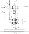
도 1은 본 발명의 바람직한 실시예에 따른 동력 발생 장치가 스텁 장착부 상에 설치된 모습을 도시한 측면도이다.
도 2는 본 발명의 바람직한 실시예에 따른 동력 발생 장치를 명료함을 위해 장착부와 다른 동력 발생 장치로부터 분리된 상태로 도시한 사시도이다.
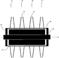
도 3은 연장된 주 샤프트들을 양 단부에 구비한 도 2의 동력 발생 장치를 도시한 측단면도이다.
도 4는 본 발명의 다른 바람직한 실시예에 따른 동력 발생 장치를 개략적으로 도시한 측면도이다.
도 5는 동력 발생 장치의 또 다른 바람직한 실시예를 개략적으로 도시한 사시도이다.
도 6은 본 발명의 바람직한 실시예를 위한 다른 장착 장치를 개략적으로 도시한 측면도이다.
도 7은 본 발명의 바람직한 실시예를 위한 또 다른 장착 장치를 개략적으로 도시한 측면도이다.1 is a side view showing a state in which a power generating device according to a preferred embodiment of the present invention is installed on a stub mounting portion.
Figure 2 is a perspective view of the power generating device according to a preferred embodiment of the present invention in a state separated from the mounting portion and other power generating device for clarity.
3 is a side cross-sectional view of the power generator of FIG. 2 with extended main shafts at both ends; FIG.
Figure 4 is a side view schematically showing a power generating device according to another preferred embodiment of the present invention.
5 is a perspective view schematically showing another preferred embodiment of the power generating device.
6 is a side view schematically showing another mounting apparatus for the preferred embodiment of the present invention.
7 is a side view schematically showing another mounting apparatus for the preferred embodiment of the present invention.
도 1 내지 도 3을 참조하면, 대체로 도면 번호 10으로 지시된 동력 발생기 또는 동력 발생 장치가 도시되어 있다. 동력 발생 장치(10)는 회전축(15)을 중심으로 회전하도록 구성된 회전자(13)를 포함하는 본체(12)를 포함하며, 상기 회전자(13)는 환형 몸체 또는 중공 실린더 또는 케이싱(17)을 포함하는 일체형 회전자 몸체(14)를 포함한다. 본체(12)는 일체형 회전자 몸체(14) 내부에 배치된 고정자 몸체(62)를 포함한다.1 to 3, there is shown a power generator or power generating device, generally indicated at 10. The
다수의 블레이드(18)들을 포함하는 블레이드 조립체(16)가 마련되며, 다수의 블레이드들은 환형 몸체 또는 중공 실린더 또는 케이싱(17)의 원주상 외벽에 작동 가능하게 장착되고 상기 원주상 외벽으로부터 반경 방향으로 연장되고, 사용 시에는 수역(body of water)으로 연장된다. 블레이드(18)들은 군(tiers)으로 또는 단(團)(bands)(19)으로 배치되고, 도시된 실시예에서는 블레이드 조립체에 네 개의 블레이드(18) 군이 있다. 여려 가지 실시예에서, 임의의 적절한 개수의 블레이드 단 또는 군이 마련될 수 있고, 2, 4, 6, 8, 10, 12, 15, 20, 25, 30, 40, 50, 75, 100, 150, 200, 500, 750, 1000, 1250, 1500, 2000 또는 5000군 또는 단을 포함한다. 블레이드 카세트가 회전자 몸체의 축을 따라 종방향으로 위치될 수 있고, 종방향 그룹으로 장착되고 제거될 수 있는데, 그 구성을 도시하지는 않았지만 당업자라면 쉽게 알 수 있을 것이다. A
도시된 블레이드(18)들은 모두 길이가, 0.5 내지 1m로 서로 동일하다. 어떤 실시예들에서는, 다른 동력 발생기(5)들의 블레이드(3)와 같은 다른 구조 요소에 가까운 정도에 따라서 그리고 또한 블레이드(18)들과 전체 동력 발생 장치(10)의 희망하는 효율과 강도에 따라서 이 길이는 약 3m 이상까지 연장될 수 있다. 다른 실시예들에서는, 블레이드(18)들은, 예를 들어 도 1에 도시된 바와 같은 실시예에서는 어느 정도는 터빈 블레이드(3)에 가까운 정도로 인해 상부에 있는 하나 또는 두 개의 블레이드 군이 하부에 있는 두 개의 블레이드 군보다 짧도록, 회전축(15)을 따르는 위치에 따라 길이가 변할 수 있으며, 도면에는 블레이드들의 길이가 변하지 않는 것으로 도시되었지만 블레이드들은 그러한 특징을 포함할 수 있다. 물의 전단 유동 개념으로 인해 해류의 유입 방향과 속도는 해저로부터의 높이에 따라 그리고 그에 따른 회전축(15)을 따르는 위치에 따라 변할 것이라는 것을 알 수 있을 것이다. 따라서 블레이드 조립체들과 블레이드들의 길이, 비틀림(twist), 코드(chord) 길이, 코드 곡률 및 두께, 받음각 및 기타 변수들이 적절히 변경될 수 있다. The
블레이드(18)들은 양방향성이고 그 피치(pitch)는 내장된 서보 모터 또는 다른 장치(미도시)에 의해 변할 수 있다. 그러나, 바람직한 실시예에서는, 블레이드(18)들은 일방향성이고, 피치가 고정되어 있으며 모두 길이가 서로 비슷하다. 도시된 블레이드(18)들은 U형, V형 또는 갈매기 무늬(chevron) 형상이며, 도 1의 위에서 볼 때 시계 방향인 방향으로 회전자와 케이싱을 구동시키는 포획부(catch portion)(오목부로 도시됨)를 포함한다. 바람직하게는, 동력 발생 장치가 대체로 수직으로 장착되면, 블레이드(18)들은 임의의 수평 방향으로부터의 해류 또는 수류에 의해서 작동되어 유입되는 해류의 방향과 속도에 관계없이 동일한 방향으로 항상 회전하도록 구성된다. 유동 중에 수평 성분이 없으면, 회전자가 회전하기 어려울 것이다. 동력 발생 장치가 임의의 방향으로 장착되는 경우에도 블레이드들은 여전히 회전자를 선택된 방향으로 회전시킬 것이다. The
블레이드(18)들은 단부 쪽으로 이어지는 테이퍼를 포함하고, 블레이드 효율 또는 동력을 증가시키도록 진행 방향과 반대 방향으로 뻗거나(swept) 혹은 경사질 수 있다.The
본체(12) 및/또는 회전자(13)는 구조적으로 주기둥 조립체(pylon assembly)(8)의 말단부 또는 원위 단부(7)에 장착된 보조 동력 발생기(5)를 지지하기에 적당하다. 보조 동력 발생기(5)는 회전축(2)을 중심으로 회전하도록 회전 가능하게 장착된 다수의 블레이드(3)를 포함하는 블레이드 세트(4)를 포함한다. 터빈 하우징(1)은 회전축(2)(도 1에서는 회전축(15)과 일치함)을 중심으로 조정되어 계속 변하는 유입 해류(W)를 가장 효과적으로 포획(capture)할 수 있도록 주기둥 조립체(8) 상에 회전가능하게 장착되어 있다. The
동력 발생기(10)는 해저에 장착되고, 대체로 또는 실질적으로 상방으로 연장되고, 그리고 발생된 동력이 수압 파이프(hydraulic pipe) 또는 전력 케이블을 통해 해변가의 저장 장소 또는 분배망으로 전달될 수 있는 독립형 동력 발생기이다. 선택적인 실시예에서는, 동력 발생기(10)는 보조 동력 발생 기계(5)를 구조적으로 지지하고 보조 동력 발생기(5)에 수압 동력 및/또는 서비스를 공급하거나 혹은 보조 동력 발생기(5)에 전력을 공급할 수 있다. 또한, 동력 발생기(5)와 여기서 상세하게 설명한 본 발명의 동력 발생기(10)가 동일한 분배망을 공유하는 것도 고려할 수 있다. The
어떤 구성들(도 5 내지 도 7)에서는, 동력 발생기는 독립형 장치이고, 본체(12)와 회전자(13)는 해류(W)의 유동과 직교하도록 수평으로 연장될 수 있다. 이러한 구성들에서는 본체 또는 본체들은 주기둥 조립체(8)들로부터 연장되는 수평 암들 상에 장착될 것이다. In some configurations (FIGS. 5-7), the power generator is a standalone device, and the
도 1 및 모든 도면들을 다시 언급하면, 본체(12)와 회전자(13)는 회전자 몸체(60)와 고정자 몸체(62)를 포함한다. 고정자 몸체(62)는 회전자 몸체(60)와 일체형 회전자 몸체(14) 내부에 배치되어 있다. 회전자 몸체(60)는 케이싱(17)이 회전할 때 케이싱(17)과 동일한 속도로 케이싱과 함께 회전하도록 케이싱(14)의 내면에 대해 또는 케이싱(14)과 일체로 장착된다. 회전자 몸체(60)와 고정자 몸체(62)는 발전기와 모터에서는 일반적인 바와 같이 전기 권선들을 포함하고 있으며, 이들의 상대 회전에 의해 사용 또는 후속적인 저장을 위해 전력망 또는 저장 스테이션으로 전달될 수 있는 전력이 발생된다. Referring again to FIG. 1 and all figures, the
동력 발생 장치(10)를 설치하도록, 기부 또는 주기둥 기부(50)가 수역(54)의 바닥(52)에 위치된다. 스텁 또는 보스(56)가 베이스(50)에 제거 가능하게 삽입될 수 있거나 혹은 베이스(50)와 일체일 수 있다. 그리고 나서 본체(12)가 스텁 또는 보스(56) 상에 회전 가능하게 장착된다. 그리고 나서 주기둥 조립체(8)의 원위부(58)가 본체(12)의 원위 단부 상에 설치된다. 원위부(58)는 동력 발생기(5)의 회전을 위한 회전 유닛(59)을 포함한다. 그리고 나서 동력 발생기(5)가 주기둥 조립체(8)의 원위 단부(7) 상에 제거 가능하게 장착된다. 유입 해류(W)로부터의 동력은 추출되어 소비자가 사용할 수 있게 동력망으로 전송되거나 혹은 나중에 사용하기 위해 저장소로 전송될 수 있다. To install the
도 3에는 회전자 몸체 권선(60)과 고정된 고정자 몸체 권선(62)이 개략적으로 도시되어 있다. 회전자(60)가 매우 얇게 도시되어 있지만, 이 도면은 단지 개략적일 뿐이며 주요 부품들의 일반 개념적인 구성을 도시한다. 역시 고정자 몸체 권선(62)에 고정된 샤프트(70)는 고정자 몸체 권선의 양 단부로부터 연장된다. 3 schematically shows a rotor body winding 60 and a fixed stator body winding 62. Although the
본 설명란에서 한 실시예의 부품들과 관련된 동일한 도면 번호들은 다르게 지시하지 않는 한 다른 실시예의 유사한 부품들을 지시한다. In the description, the same reference numerals associated with the parts of one embodiment refer to like parts of another embodiment unless otherwise indicated.
도 4에는 다른 바람직한 실시예의 개략적인 구성이 도시되어 있는데, 샤프트(170)에 의해 구동되는 통상의 구성(고정자 내부에 회전자가 있음)으로 회전자 몸체(160)와 고정자 몸체(162)를 구비한 본체(112) 근처에 배치된 통상의 동력 발생기(180)가 도시되어 있다. A schematic configuration of another preferred embodiment is shown in FIG. 4, which has a
도 5에는 다리부(leg)들 또는 암(82)들 상에 장착된 고정 샤프트(70)들을 구비한 도 3의 동력 발생 장치가 도시되어 있다. 다리부들 또는 암들은 해저에 장착된 플랫폼(미도시)에 장착되거나 혹은 해저(94)에 직접 장착된다. FIG. 5 shows the power generator of FIG. 3 with
도 6에는 본체(12)와 회전자(13)가 요축(yaw axis)(91)을 중심으로 회전할 수 있도록 턴테이블 장치(turntable apparatus) 상에 장착된 고정 샤프트(70)들을 구비한 도 3의 동력 발생 장치가 도시되어 있다. 회전은 롤축 또는 피치축을 포함하는 다른 축을 중심으로 이루어질 수 있다.FIG. 6 of FIG. 3 with
도 7에는 부양 챔버(buoyancy chamber)(95)들과, 고정 주 샤프트(97)들에 부착된 케이블(98, 99)들을 포함하는 장착 장치를 포함하는 도 3의 동력 발생 장치가 도시되어 있다. 해저(94)에 장착된 윈치(96)들이 본체(12)와 회전자(13)가 부양 챔버(95)들의 부력(어떤 실시예에서는 가변적임)의 영향 하에서 상승하여 해저(94) 위의 여러 깊이에서 세기가 변하는 해류에 접근할 수 있도록 사용 중에 연장된다. 다리부들과 암들과 케이블들은 회전자 몸체의 자세를 경사진 자세 또는 수평으로부터 수직으로 조정하도록 각기 다른 길이들로 또는 가변적인 길이로 연장될 수 있다. FIG. 7 shows the power generating device of FIG. 3 including
본체(12)와 회전자(13)의 가장 효과적인 높이를 지시하도록 주변 환경과 동력 발생기 성능의 여러 파라미터들을 감시하도록 감시 및 제어 시스템(미도시)이 마련될 수 있다. A monitoring and control system (not shown) may be provided to monitor various parameters of the environment and power generator performance to indicate the most effective height of the
블레이드들을 과도하게 빠른 해류로부터 보호할 수 있도록 제동기가 마련될 수 있다. A brake can be provided to protect the blades from excessively fast currents.
본 발명이 속하는 기술 분야에서 통상의 지식을 가진 자라면 광범위하게 기재된 본 발명의 기술적 사상 또는 범위를 벗어나지 않고 특정 실시예들에 도시된 바와 같이 본 발명에 대해 여러 가지로 변형 및/또는 개조를 할 수 있음을 알 것이다. 따라서 명세서의 발명의 상세한 설명에 기재된 실시예들은 모든 측면에서 예시적이고 비제한적이라는 점을 감안해야 한다. Those skilled in the art to which the present invention pertains may make various modifications and / or modifications to the present invention as shown in the specific embodiments without departing from the broader technical spirit or scope of the present invention. You will know. It is therefore to be considered that the embodiments described in the detailed description of the invention are illustrative and non-limiting in all respects.
Claims (21)
상기 회전자 몸체와 고정자 몸체는 상기 회전자 몸체와 고정자 몸체가 각각 전기 권선을 포함하는 발전 장치의 형태인 것을 특징으로 하는 수중 동력 발생 장치.The method of claim 1,
The rotor body and the stator body are underwater power generator, characterized in that the rotor body and the stator body is in the form of a power generation device each comprising an electrical winding.
상기 회전자 몸체 및/또는 고정자 몸체는 펌프 기구를 포함하는 것을 특징으로 하는 수중 동력 발생 장치.The method of claim 1,
The rotor body and / or the stator body comprising a pump mechanism.
상기 회전자 몸체는 사용 시에 회전축과 일치되는 중앙축을 포함하는 환형 몸체 또는 중공 실린더 또는 케이싱의 형태인 것을 특징으로 하는 수중 동력 발생 장치.4. The method according to any one of claims 1 to 3,
The rotor body is in the form of an annular body or hollow cylinder or casing comprising a central axis coinciding with the axis of rotation in use.
상기 블레이드 조립체는 환형 몸체 또는 중공 실린더의 외주벽 상에 장착된 것을 특징으로 하는 수중 동력 발생 장치. The method of claim 4, wherein
And the blade assembly is mounted on an outer circumferential wall of the annular body or the hollow cylinder.
상기 실린더는, 사용 시에, 해저에 장착된 주기둥 기부로부터 연장되는 주기둥에 작동 가능하게 또는 다른 방식으로 연결된 것을 특징으로 하는 수중 동력 발생 장치. The method according to claim 4 or 5,
The cylinder, when in use, is operatively or otherwise connected to a pillar extending from a periodic base mounted on the seabed.
상기 회전자 몸체는 회전자 몸체의 말단부 또는 두부(head end)에 배치된 보조 동력 발생기에 작동 가능하게 또는 다른 방식으로 연결된 것을 특징으로 하는 수중 동력 발생 장치.The method according to any one of claims 1 to 6,
The rotor body is operatively or otherwise connected to an auxiliary power generator disposed at the distal end or the head end of the rotor body.
상기 블레이드 조립체는 회전자 몸체의 외주벽 상에 배치된 다수의 블레이드 단(band) 또는 군(tier)의 형태인 것을 특징으로 하는 수중 동력 발생 장치.The method according to any one of claims 1 to 7,
And the blade assembly is in the form of a plurality of blade bands or tiers disposed on the outer circumferential wall of the rotor body.
약 두 개 내지 이천 개의 블레이드 단 또는 군이 마련된 것을 특징으로 하는 수중 동력 발생 장치.The method of claim 8,
An underwater power generator, characterized in that about two to two thousand blade stages or groups are provided.
약 네 개 내지 열두 개의 블레이드 단 또는 군이 마련된 것을 특징으로 하는 수중 동력 발생 장치.10. The method of claim 9,
An underwater power generator, characterized in that about four to twelve blade stages or groups are provided.
상기 블레이드들은 단면이 U형, V형 또는 갈매기 무늬형이고, 오목한 단면 형태의 포획부와 볼록부 형태의 머리부 또는 전방부를 포함하는 것을 특징으로 하는 수중 동력 발생 장치.The method according to any one of claims 1 to 10,
The blades are U-shaped, V-shaped or chevron-shaped cross-section, submerged power generation apparatus characterized in that it comprises a concave cross-sectional capture and convex head or front.
상기 블레이드들은 블레이드들의 횡단면이 팁부에서 루트부에서보다 더 작도록 테이퍼진 것을 특징으로 하는 수중 동력 발생 장치.The method according to any one of claims 1 to 11,
And said blades are tapered such that the cross section of the blades is smaller at the tip than at the root.
블레이드 단들은 제거 가능한 것을 특징으로 하는 수중 동력 발생 장치.11. The method according to any one of claims 8 to 10,
Underwater power generating unit, characterized in that the blade stages are removable.
상기 블레이드들은 카트리지식 구성과 같은 구성으로 제거 가능하고, 이에 따라 몇 개의 블레이드들이 카트리지 조립체의 제거에 의해 한 번의 제거 작업으로 제거될 수 있는 것을 특징으로 하는 수중 동력 발생 장치. The method of claim 12,
And the blades are removable in a configuration such as a cartridge type configuration, whereby several blades can be removed in one removal operation by removal of the cartridge assembly.
상기 블레이드의 받음각 및/또는 길이는 유입되는 조류의 방향과 속도의 변화를 이용하여 블레이드 효율 및/또는 출력을 증가시키도록 회전자의 길이를 따르는 위치에 따라 변하는 것을 특징으로 하는 수중 동력 발생 장치.The method according to any one of claims 1 to 13,
And the angle of attack and / or length of the blade varies with position along the length of the rotor to increase blade efficiency and / or output by using a change in direction and speed of incoming tidal flow.
상기 회전자는 일체형 회전자 몸체를 포함하고, 상기 일체형 회전자 몸체는 그 내부에 배치된 고정자 몸체를 중심으로 회전하여 유용한 동력을 발생시키도록 구성되며,
상기 회전자 장치는 해저의 장착부로부터 연장되는 하나 이상의 암 또는 케이블 상에 대체로 수평으로 장착된 것을 특징으로 하는 수중 동력 발생 장치.A rotor configured to rotate about an axis of rotation and having a blade assembly, the blade assembly operatively mounted to the rotor and extending therefrom and actuated by a flow of water from a direction generally orthogonal to the axis of rotation An underwater power generating device comprising a plurality of blades configured to rotate electrons,
The rotor comprises an integral rotor body, the integral rotor body is configured to rotate about the stator body disposed therein to generate useful power,
And the rotor device is mounted substantially horizontally on at least one arm or cable extending from the mounting of the seabed.
상기 암들 또는 케이블들은 고정 샤프트가 해저에 대해 예각으로 장착되도록 길이가 서로 다를 수 있는 것을 특징으로 하는 수중 동력 발생 장치.16. The method of claim 15,
And the arms or cables can be different in length so that the fixed shaft is mounted at an acute angle with respect to the seabed.
상기 암들 또는 케이블들은 요축(yaw axis), 피치축(pitch axis) 또는 롤축(roll axis)을 중심으로 회전되도록 턴테이블 또는 다른 장치 상에 장착된 것을 특징으로 하는 수중 동력 발생 장치.17. The method according to claim 15 or 16,
And the arms or cables are mounted on a turntable or other device to be rotated about a yaw axis, a pitch axis or a roll axis.
상기 케이블들 또는 암들은 본체가 해역 또는 수역의 각기 다른 깊이에서 수류 내에 배치될 수 있도록 연장 가능하거나 혹은 연장되는 것을 특징으로 하는 수중 동력 발생 장치.The method according to any one of claims 15 to 17,
Wherein said cables or arms are extensible or extendable such that the body can be disposed in the water stream at different depths of the sea or the body of water.
상기 회전자 몸체는 각기 다른 높이들에서 서로 다른 수류들에 접근할 수 있게 하는 조정 가능한 부양체(buoyancy)를 포함하는 것을 특징으로 하는 수중 동력 발생 장치.19. The method according to any one of claims 1 to 18,
The rotor body includes an adjustable buoyancy that allows access to different streams of water at different heights.
상기 케이블들은 해저에 장착된 윈치 또는 다른 권취 및 전개 장치(take up and deployment apparatus)에 의해 연장될 수 있는 것을 특징으로 하는 수중 동력 발생 장치.The method according to any one of claims 15 to 19,
Wherein the cables can be extended by a winch or other take up and deployment apparatus mounted to the seabed.
Applications Claiming Priority (2)
| Application Number | Priority Date | Filing Date | Title |
|---|---|---|---|
| AU2009904330A AU2009904330A0 (en) | 2009-09-08 | Direct Drive Underwater Turbine | |
| AU2009904330 | 2009-09-08 |
Publications (1)
| Publication Number | Publication Date |
|---|---|
| KR20120076355A true KR20120076355A (en) | 2012-07-09 |
Family
ID=43731852
Family Applications (1)
| Application Number | Title | Priority Date | Filing Date |
|---|---|---|---|
| KR1020127009056A KR20120076355A (en) | 2009-09-08 | 2010-09-08 | Power generator |
Country Status (9)
| Country | Link |
|---|---|
| US (1) | US20120267895A1 (en) |
| EP (1) | EP2475822A1 (en) |
| JP (1) | JP2013503994A (en) |
| KR (1) | KR20120076355A (en) |
| CN (1) | CN102482858A (en) |
| AU (1) | AU2010292974A1 (en) |
| CA (1) | CA2772764A1 (en) |
| CL (1) | CL2012000602A1 (en) |
| WO (1) | WO2011029138A1 (en) |
Families Citing this family (12)
| Publication number | Priority date | Publication date | Assignee | Title |
|---|---|---|---|---|
| EP2304225B1 (en) * | 2008-04-14 | 2015-10-14 | Atlantis Resources Corporation Pte Limited | Blade for a water turbine |
| CA2724702C (en) | 2008-04-14 | 2014-09-02 | Atlantis Resources Corporation Pte Limited | Central axis water turbine with rearwardly raked/tilted blades |
| EP2425122A4 (en) | 2009-04-28 | 2013-03-20 | Atlantis Resources Corp Pte | Underwater power generator |
| AU2010312315B2 (en) | 2009-10-27 | 2013-05-23 | Atlantis Resources Corporation Pte Limited | Underwater power generator |
| CN102128128A (en) * | 2011-03-23 | 2011-07-20 | 刘华栋 | Permanent magnet direct drive type tidal current power generation device |
| AU2012253228B2 (en) | 2011-05-10 | 2013-07-11 | Atlantis Resources Corporation Pte Limited | Deployment apparatus and method of deploying an underwater power generator |
| KR200460486Y1 (en) * | 2011-12-01 | 2012-05-23 | 손호윤 | Pillar type wind electric power generator |
| FR3003312A1 (en) * | 2013-03-13 | 2014-09-19 | Maurice Pasblancq | DEVICE FOR TRANSFORMING THE KINETIC ENERGY OF A FLUID INTO MECHANICAL ENERGY |
| US9334847B2 (en) | 2013-12-23 | 2016-05-10 | Grover Curtis Harris | Bi-rotational generator |
| EP3394428B1 (en) * | 2015-12-22 | 2021-04-21 | Vestas Wind Systems A/S | Wind turbine system with time distributed transitions |
| EP3203063A1 (en) * | 2016-02-03 | 2017-08-09 | Wilhelmus Helena Hendrikus Joosten | Wind turbine, its use and a vane for use in the turbine |
| CN106762377A (en) * | 2016-12-07 | 2017-05-31 | 天津大学 | It is fixed on the ocean power generation device of jack-up unit spud leg |
Family Cites Families (25)
| Publication number | Priority date | Publication date | Assignee | Title |
|---|---|---|---|---|
| US3604942A (en) * | 1970-05-11 | 1971-09-14 | Curtis A Nelson | Underwater generator |
| JPS521346A (en) * | 1975-06-24 | 1977-01-07 | U M I:Kk | Power generating process availing ocean current and its device |
| US4306157A (en) * | 1979-06-20 | 1981-12-15 | Wracsaricht Lazar J | Underwater slow current turbo generator |
| JPH10225075A (en) * | 1997-02-10 | 1998-08-21 | Hisasuke Kumazawa | Fluid generator |
| DK174156B1 (en) * | 2000-04-03 | 2002-07-29 | Henrik Frans Christensen | Wind and wave energy systems |
| US6856036B2 (en) * | 2001-06-26 | 2005-02-15 | Sidney Irving Belinsky | Installation for harvesting ocean currents (IHOC) |
| AU2002328217B2 (en) * | 2001-09-17 | 2005-09-22 | Clean Current Limited Partnership | Underwater ducted turbine |
| CN2528952Y (en) * | 2002-02-05 | 2003-01-01 | 徐永长 | Fluid energy commutator |
| GB0306809D0 (en) * | 2003-03-25 | 2003-04-30 | Marine Current Turbines Ltd | Water current powered turbines installed on a deck or "false seabed" |
| KR20040107166A (en) * | 2003-06-12 | 2004-12-20 | 학교법인 인하학원 | Helical type offshore combined generating system |
| SE526789C2 (en) * | 2004-03-16 | 2005-11-08 | Uppsala Power Man Consultants | Aggregates comprising a water turbine and a generator, the rotor of which is directly connected to each of the turbine blades |
| EP1876350A4 (en) * | 2005-04-11 | 2014-01-01 | Vidal Maria Elena Novo | Electric power generator system using ring-shaped generators |
| US7199484B2 (en) * | 2005-07-05 | 2007-04-03 | Gencor Industries Inc. | Water current generator |
| ATE464475T1 (en) * | 2005-12-29 | 2010-04-15 | Georg Hamann | DEVICE AND SYSTEM FOR GENERATING REGENERATIVE AND RENEWABLE ENERGY FROM WATER |
| US8206113B2 (en) * | 2006-06-02 | 2012-06-26 | Ryynaenen Seppo | Method and apparatus for converting marine wave energy by means of a difference in flow resistance form factors into electricity |
| KR100872992B1 (en) * | 2006-11-13 | 2008-12-08 | 라소선 | Submarine fixation type sea structure which carries out the function of artificial reef and manufacturing method thereof |
| WO2008115558A1 (en) * | 2007-03-20 | 2008-09-25 | Zeuner Kenneth W | System and method for harvesting electrical power from marine current using turbines |
| US20080236159A1 (en) * | 2007-03-27 | 2008-10-02 | Glenn Martin Tierney | Cycloidal power generator |
| WO2009015419A1 (en) * | 2007-07-30 | 2009-02-05 | Buoyancy Hydro Pty Ltd | Buoyancy hydro power generator and method |
| JP2009036113A (en) * | 2007-08-02 | 2009-02-19 | Mitsunori Kitagawa | Submerged generator |
| DE102009015044A1 (en) * | 2008-05-02 | 2009-11-05 | Hartmuth Drews | Segment wreath ring generator |
| US20100066089A1 (en) * | 2008-09-12 | 2010-03-18 | Bruce Best | Subsea turbine with a peripheral drive |
| GB0910867D0 (en) * | 2009-06-24 | 2009-08-05 | Design Tech & Innovation Ltd | Water power generators |
| ITPI20090128A1 (en) * | 2009-10-19 | 2011-04-20 | Re Co 2 S R L | SUBMERSIBLE EQUIPMENT TO OBTAIN ELECTRICAL ENERGY FROM FLUVIAL AND MARINE CURRENTS |
| US20120086207A1 (en) * | 2010-10-07 | 2012-04-12 | Dennis John Gray | Simplified Paddlewheel Energy Device |
-
2010
- 2010-09-08 WO PCT/AU2010/001161 patent/WO2011029138A1/en active Application Filing
- 2010-09-08 US US13/394,673 patent/US20120267895A1/en not_active Abandoned
- 2010-09-08 EP EP10814802A patent/EP2475822A1/en not_active Withdrawn
- 2010-09-08 JP JP2012527158A patent/JP2013503994A/en active Pending
- 2010-09-08 CA CA2772764A patent/CA2772764A1/en not_active Abandoned
- 2010-09-08 AU AU2010292974A patent/AU2010292974A1/en not_active Abandoned
- 2010-09-08 CN CN2010800399115A patent/CN102482858A/en active Pending
- 2010-09-08 KR KR1020127009056A patent/KR20120076355A/en not_active Application Discontinuation
-
2012
- 2012-03-07 CL CL2012000602A patent/CL2012000602A1/en unknown
Also Published As
| Publication number | Publication date |
|---|---|
| JP2013503994A (en) | 2013-02-04 |
| EP2475822A1 (en) | 2012-07-18 |
| CN102482858A (en) | 2012-05-30 |
| US20120267895A1 (en) | 2012-10-25 |
| AU2010292974A1 (en) | 2012-03-22 |
| WO2011029138A1 (en) | 2011-03-17 |
| CL2012000602A1 (en) | 2012-07-06 |
| CA2772764A1 (en) | 2011-03-17 |
Similar Documents
| Publication | Publication Date | Title |
|---|---|---|
| KR20120076355A (en) | Power generator | |
| JP5539893B2 (en) | Power generator | |
| US7397144B1 (en) | Bearing-less floating wind turbine | |
| US8080913B2 (en) | Hollow turbine | |
| CN102066667B (en) | Central axis water turbine | |
| RU2435069C2 (en) | Device and system for generation of regenerative and renewable hydraulic energy | |
| US7750492B1 (en) | Bearingless floating wind turbine | |
| KR101548039B1 (en) | Methods for Installing and Maintaining of water flow power unit of soaking type | |
| US8461711B2 (en) | Counter rotation subsurface current generator | |
| KR20110010479A (en) | A power generation machine structure using water wheel | |
| WO2008093037A1 (en) | Apparatus for generating electrical power | |
| US20100123316A1 (en) | Power generator barge | |
| JP2011064097A (en) | Wind turbine device and wind turbine generator using the same | |
| CN110374828B (en) | Offshore wind power generation equipment with heat dissipation function and high safety and reliability | |
| US7956486B2 (en) | Windmill electric generator for hydroelectric power system | |
| US20160172934A1 (en) | Contra rotor wind turbine system using a hydraulic power transmission device | |
| KR101262579B1 (en) | The device of all in one velocity hydro power plant With variable speed nunner turbine | |
| KR20120038707A (en) | Floating offshore wind power generation plant | |
| JP2019515193A (en) | Tidal generator | |
| SE462294B (en) | TURBINE DEVICE | |
| KR101318480B1 (en) | Multi-stage tidal current power plant with high efficiency | |
| JP5890707B2 (en) | Wave power generator | |
| AU2014201185A1 (en) | Power Generator | |
| WO2018203183A1 (en) | Flow turbine for hydro power plants | |
| NL1035907C (en) | DEVICE FOR SUPPORTING AN OFFSHORE WIND TURBINE. |
Legal Events
| Date | Code | Title | Description |
|---|---|---|---|
| WITN | Application deemed withdrawn, e.g. because no request for examination was filed or no examination fee was paid |