KR20120020189A - Stented prosthetic heart valves - Google Patents
Stented prosthetic heart valves Download PDFInfo
- Publication number
- KR20120020189A KR20120020189A KR1020117031714A KR20117031714A KR20120020189A KR 20120020189 A KR20120020189 A KR 20120020189A KR 1020117031714 A KR1020117031714 A KR 1020117031714A KR 20117031714 A KR20117031714 A KR 20117031714A KR 20120020189 A KR20120020189 A KR 20120020189A
- Authority
- KR
- South Korea
- Prior art keywords
- stent
- valve
- stent structure
- leaflets
- bioprosthesis
- Prior art date
Links
Images


Classifications
-
- A—HUMAN NECESSITIES
- A61—MEDICAL OR VETERINARY SCIENCE; HYGIENE
- A61F—FILTERS IMPLANTABLE INTO BLOOD VESSELS; PROSTHESES; DEVICES PROVIDING PATENCY TO, OR PREVENTING COLLAPSING OF, TUBULAR STRUCTURES OF THE BODY, e.g. STENTS; ORTHOPAEDIC, NURSING OR CONTRACEPTIVE DEVICES; FOMENTATION; TREATMENT OR PROTECTION OF EYES OR EARS; BANDAGES, DRESSINGS OR ABSORBENT PADS; FIRST-AID KITS
- A61F2/00—Filters implantable into blood vessels; Prostheses, i.e. artificial substitutes or replacements for parts of the body; Appliances for connecting them with the body; Devices providing patency to, or preventing collapsing of, tubular structures of the body, e.g. stents
- A61F2/02—Prostheses implantable into the body
- A61F2/24—Heart valves ; Vascular valves, e.g. venous valves; Heart implants, e.g. passive devices for improving the function of the native valve or the heart muscle; Transmyocardial revascularisation [TMR] devices; Valves implantable in the body
- A61F2/2412—Heart valves ; Vascular valves, e.g. venous valves; Heart implants, e.g. passive devices for improving the function of the native valve or the heart muscle; Transmyocardial revascularisation [TMR] devices; Valves implantable in the body with soft flexible valve members, e.g. tissue valves shaped like natural valves
- A61F2/2418—Scaffolds therefor, e.g. support stents
-
- A—HUMAN NECESSITIES
- A61—MEDICAL OR VETERINARY SCIENCE; HYGIENE
- A61F—FILTERS IMPLANTABLE INTO BLOOD VESSELS; PROSTHESES; DEVICES PROVIDING PATENCY TO, OR PREVENTING COLLAPSING OF, TUBULAR STRUCTURES OF THE BODY, e.g. STENTS; ORTHOPAEDIC, NURSING OR CONTRACEPTIVE DEVICES; FOMENTATION; TREATMENT OR PROTECTION OF EYES OR EARS; BANDAGES, DRESSINGS OR ABSORBENT PADS; FIRST-AID KITS
- A61F2/00—Filters implantable into blood vessels; Prostheses, i.e. artificial substitutes or replacements for parts of the body; Appliances for connecting them with the body; Devices providing patency to, or preventing collapsing of, tubular structures of the body, e.g. stents
- A61F2/02—Prostheses implantable into the body
- A61F2/04—Hollow or tubular parts of organs, e.g. bladders, tracheae, bronchi or bile ducts
- A61F2/06—Blood vessels
- A61F2/07—Stent-grafts
-
- A—HUMAN NECESSITIES
- A61—MEDICAL OR VETERINARY SCIENCE; HYGIENE
- A61F—FILTERS IMPLANTABLE INTO BLOOD VESSELS; PROSTHESES; DEVICES PROVIDING PATENCY TO, OR PREVENTING COLLAPSING OF, TUBULAR STRUCTURES OF THE BODY, e.g. STENTS; ORTHOPAEDIC, NURSING OR CONTRACEPTIVE DEVICES; FOMENTATION; TREATMENT OR PROTECTION OF EYES OR EARS; BANDAGES, DRESSINGS OR ABSORBENT PADS; FIRST-AID KITS
- A61F2/00—Filters implantable into blood vessels; Prostheses, i.e. artificial substitutes or replacements for parts of the body; Appliances for connecting them with the body; Devices providing patency to, or preventing collapsing of, tubular structures of the body, e.g. stents
- A61F2/02—Prostheses implantable into the body
- A61F2/28—Bones
-
- A—HUMAN NECESSITIES
- A61—MEDICAL OR VETERINARY SCIENCE; HYGIENE
- A61F—FILTERS IMPLANTABLE INTO BLOOD VESSELS; PROSTHESES; DEVICES PROVIDING PATENCY TO, OR PREVENTING COLLAPSING OF, TUBULAR STRUCTURES OF THE BODY, e.g. STENTS; ORTHOPAEDIC, NURSING OR CONTRACEPTIVE DEVICES; FOMENTATION; TREATMENT OR PROTECTION OF EYES OR EARS; BANDAGES, DRESSINGS OR ABSORBENT PADS; FIRST-AID KITS
- A61F2/00—Filters implantable into blood vessels; Prostheses, i.e. artificial substitutes or replacements for parts of the body; Appliances for connecting them with the body; Devices providing patency to, or preventing collapsing of, tubular structures of the body, e.g. stents
- A61F2/82—Devices providing patency to, or preventing collapsing of, tubular structures of the body, e.g. stents
-
- A—HUMAN NECESSITIES
- A61—MEDICAL OR VETERINARY SCIENCE; HYGIENE
- A61F—FILTERS IMPLANTABLE INTO BLOOD VESSELS; PROSTHESES; DEVICES PROVIDING PATENCY TO, OR PREVENTING COLLAPSING OF, TUBULAR STRUCTURES OF THE BODY, e.g. STENTS; ORTHOPAEDIC, NURSING OR CONTRACEPTIVE DEVICES; FOMENTATION; TREATMENT OR PROTECTION OF EYES OR EARS; BANDAGES, DRESSINGS OR ABSORBENT PADS; FIRST-AID KITS
- A61F2220/00—Fixations or connections for prostheses classified in groups A61F2/00 - A61F2/26 or A61F2/82 or A61F9/00 or A61F11/00 or subgroups thereof
- A61F2220/0025—Connections or couplings between prosthetic parts, e.g. between modular parts; Connecting elements
- A61F2220/0075—Connections or couplings between prosthetic parts, e.g. between modular parts; Connecting elements sutured, ligatured or stitched, retained or tied with a rope, string, thread, wire or cable
-
- A—HUMAN NECESSITIES
- A61—MEDICAL OR VETERINARY SCIENCE; HYGIENE
- A61F—FILTERS IMPLANTABLE INTO BLOOD VESSELS; PROSTHESES; DEVICES PROVIDING PATENCY TO, OR PREVENTING COLLAPSING OF, TUBULAR STRUCTURES OF THE BODY, e.g. STENTS; ORTHOPAEDIC, NURSING OR CONTRACEPTIVE DEVICES; FOMENTATION; TREATMENT OR PROTECTION OF EYES OR EARS; BANDAGES, DRESSINGS OR ABSORBENT PADS; FIRST-AID KITS
- A61F2230/00—Geometry of prostheses classified in groups A61F2/00 - A61F2/26 or A61F2/82 or A61F9/00 or A61F11/00 or subgroups thereof
- A61F2230/0002—Two-dimensional shapes, e.g. cross-sections
- A61F2230/0028—Shapes in the form of latin or greek characters
- A61F2230/0054—V-shaped
Abstract
경피적 이식 장치 및 방법을 사용하여 환자 내의 위치로 이송하기 위한 스텐트 프레임(50)에 부착된 외과적 스텐트리스 판막(40)Surgical stentless valve 40 attached to stent frame 50 for transfer to a location within a patient using a percutaneous implant device and method
Description
본 발명은 인공 심장 판막에 관계한다. 보다 상세하게는, 스텐트 구조물와 조합된 인공 심장 판막과 같이 경피적 이식을 위해 외과적으로 봉합하지 않은 판막 및 그 방법에 관계한다.
The present invention relates to an artificial heart valve. More specifically, it relates to valves and methods that are not surgically closed for percutaneous implantation, such as artificial heart valves in combination with stent structures.
질병에 걸리거나 결함이 있는 심장 판막들은 서로 다른 유형의 다양한 심장 판막 외과수술을 사용하여 치료되거나 대체될 수 있다. 전형적인 심장 판막 외과수술들은 심장은 정지되고 혈류는 심폐 바이패스 기계(heart-lung bypass machine)에 의해 조절되는 동안 일반적인 마취하에서 수행되는 개방-심장 외과수술 절차를 수반한다. 이러한 유형의 판막 수술은 매우 침습적이고, 환자를 예를 들어, 감염, 뇌졸중, 신부전증 및 심폐 기계의 사용과 관련된 부작용과 같은 다수의 잠재적인 심각한 위험에 노출시킨다. Diseased or defective heart valves can be treated or replaced using a variety of different types of heart valve surgery. Typical heart valve surgery involves an open-heart surgery procedure performed under general anesthesia while the heart is stopped and blood flow is controlled by a heart-lung bypass machine. This type of valve surgery is very invasive and exposes the patient to a number of potential serious risks such as, for example, infections, strokes, kidney failure and side effects associated with the use of the cardiopulmonary machine.
최근, 최소 침습적이고 경피적인 심장 판막의 대체에 대한 관심이 증가하고 있다. 이러한 외과 수술 기법들은 환자 피부의 매우 작은 절개부를 형성하여 판막 조립체가 신체 내에 삽입되고 카데터와 유사한 이송 장치를 통해 심장으로 이송된다. Recently, there is increasing interest in the replacement of minimally invasive and percutaneous heart valves. These surgical techniques form a very small incision in the patient's skin such that the valve assembly is inserted into the body and transferred to the heart through a catheter-like transfer device.
임의의 응용들에서, 기법은 예를 들어, 상술한 개방-심장 외과 수술 절차와 같은 외과 수술의 보다 침습적인 형태를 선호한다. 폐동맥 판막 대체에 관하여, 미국특허공개공보 제 2003/0199971 Al호 및 2003/0199963 Al(모두 Tower, et al.에 의해 출원됨)에는 대체 폐동맥 판막으로서의 사용을 위해 팽창가능한 스텐트 내에 장착된 소 목정맥의 판막 분절이 기술되어 있다. 대체 판막은 풍선 카데터에 장착되어 혈관 시스템을 통해 경피적으로 손상된 폐동맥 판막 부위로 이송되고 풍선에 의해 팽창되어 우심실 유입관에 대하여 판막 첨판들(leaflets)을 압축하고, 대체 판막을 앵커링하고 밀봉한다. 하기 논문들 "Percutaneous Insertion of the Pulmonary Valve", Bonhoeffer, et al., Journal of the American College of Cardiology 2002; 39: 1664 - 1669 및 "Transcatheter Replacement of a Bovine Valve in Pulmonary Position", Bonhoeffer, et al., Circulation 2000; 102: 813 - 816 에 기재된 바와 같이 대체 폐동맥 판막은 판막이 있는 관 내에 위치된 본래의 폐동맥 판막 또는 인공 폐동맥 판막을 대체한다. 다향한 형태 및 구성을 가진 인공 심장 판막이 경피적 판막 수술에 사용되어 질병이 있는 천연 인간 심장 판막을 대체한다. 임의의 특정한 인공 심장 판막의 실제의 형상 및 구성은 대체된 판막(예를 들어, 승모판, 삼첨 판막, 대동맥 판막 또는 폐동맥 판막)의 임의의 크기에 의존한다. 일반적으로, 인공 심장 판막 디자인은 배치된 판막의 기능을 복제하도록 시도되고, 따라서, 생물성 인공삽입물 또는 기계 심장 판막 인공삽입물과 사용된 판막 첨판과 유사한 구조물들(valve leaflet-like structures)을 포함할 것이다. 달리 말하자면, 대체 판막들은 판막이 있는 정맥 분절을 포함하는데, 이는 팽창가능한 스텐트 내에 임의의 방식으로 장착되어 스텐트형 판막을 만든다. 경피적 이식을 위해 이러한 판막을 마련하기 위하여, 스텐트형 판막은 초기에 팽창되거나 언크림핑(uncrimped)조건으로 제공될 수 있고, 이어서 가능한 카데터의 직경에 근접할 때까지 카데터의 풍선부 주변으로 크림핑 또는 압축될 수 있다. In certain applications, the technique favors a more invasive form of surgical operation, such as, for example, the open-heart surgical procedure described above. Regarding pulmonary valve replacement, U.S. Patent Publications 2003/0199971 Al and 2003/0199963 Al (both filed by Tower, et al.) Disclose a bovine venous vein mounted in an inflatable stent for use as a replacement pulmonary valve. The valve segment of is described. The replacement valve is mounted in a balloon catheter and transported through the vascular system to the percutaneously damaged pulmonary valve area and inflated by the balloon to compress the leaflets against the right ventricular inlet tract, anchoring and sealing the replacement valve. The following articles "Percutaneous Insertion of the Pulmonary Valve", Bonhoeffer, et al., Journal of the American College of Cardiology 2002; 39: 1664-1669 and "Transcatheter Replacement of a Bovine Valve in Pulmonary Position", Bonhoeffer, et al., Circulation 2000; 102: The replacement pulmonary valve as described in 813-816 replaces the original pulmonary valve or artificial pulmonary valve located within the vessel in which the valve is located. Artificial heart valves of various shapes and configurations are used in percutaneous valve surgery to replace diseased natural human heart valves. The actual shape and configuration of any particular artificial heart valve depends on any size of the replaced valve (eg, mitral valve, tricuspid valve, aortic valve or pulmonary valve). In general, artificial heart valve designs are attempted to replicate the function of the placed valves, and thus will include valve leaflet-like structures similar to the biotic or mechanical heart valve prostheses and the valve leaflets used. will be. In other words, the replacement valves include venous segments with valves, which are mounted in any way within the inflatable stent to produce the stent valves. To prepare such valves for percutaneous implantation, the stent valves can be initially expanded or provided in uncrimped conditions, and then around the catheter's balloon until it is as close as possible to the catheter's diameter. It can be crimped or compressed.
기타 경피적으로 이송되는 인공 심장 판막들은 본원에 전체로서 참조되어 통합된 Bonhoeffer, P. et al., "Transcatheter Implantation of a Bovine Valve in Pulmonary Position." Circulation, 2002; 102:813-816, and by Cribier, A. et al. "Transcatheter Implantation of an Aortic Valve Prosthesis for Calcific Aortic Stenosis." Circulation, 2002; 106:3006-3008에서 일반적으로 유사한 구성을 갖도록 제안된다. 이러한 기법들은 적어도 부분적으로 팽창된 지지 구조물과 천연 조직 사이의 결합의 프랙셔널 형태(factional type)에 의존하여, 이송된 인공삽입물의 위치를 유지시키는데, 스텐트들은 또한 스텐트 및 때때로 스텐트를 팽창시키는데 사용되는 풍선들에 의해 제공되는 반지름 방향 힘에 대응하여 주위의 조직 내에 적어도 부분적으로 임베딩(embedded)될 수 있다. 따라서, 이러한 트랜스카데터 기법들에 의해, 환자의 천연 조직에 대한 인공 심장 판막의 종래의 봉합은 필요하지 않다. Other percutaneously transferred artificial heart valves are incorporated herein by reference in their entirety, Bonhoeffer, P. et al., "Transcatheter Implantation of a Bovine Valve in Pulmonary Position." Circulation, 2002; 102: 813-816, and by Cribier, A. et al. "Transcatheter Implantation of an Aortic Valve Prosthesis for Calcific Aortic Stenosis." Circulation, 2002; In 106: 3006-3008 it is generally proposed to have a similar configuration. These techniques maintain the position of the transferred prosthesis, depending at least in part on the fractional type of coupling between the inflated support structure and the natural tissue, which are also used to inflate the stent and sometimes the stent. It may be at least partially embedded in the surrounding tissue in response to the radial force provided by the balloons. Thus, with these transcatheter techniques, conventional closure of the artificial heart valve to the patient's natural tissue is not necessary.
유사하게, 본원에 전체로서 참조되어 통합된 Bonhoeffer, P. et al.의 논문 "Percutaneou Insertion of the Aortic Valve" J Am Coll Cardiol, 2002; 39:1664-1669, 에 생물학 판막의 경피적 이송에 대하여 기술되어 있다. 판막은 미리 이식된 판막이 있거나 판막이 없는 관 또는 미리 이식된 판막 내에서 팽창가능한 스텐트로 봉합된다. 다시, 이차적인 판막 스텐트의 방사방향 팽창은 대체 판막을 위치시키고 유지시키는데 사용된다.
Similarly, Bonhoeffer, P. et al., "Percutaneou Insertion of the Aortic Valve", J Am Coll Cardiol, 2002; 39: 1664-1669, for the percutaneous transfer of biological valves. The valve is closed with an expandable stent in a pre-grafted valve with or without a pre-grafted valve. Again, radial expansion of the secondary valve stent is used to position and maintain the replacement valve.
경피적 판막 대체 기법들 및 장치들에 대하여 발전되어 왔지만, 최소 침습적 및/또는 경피적 방식으로 이식될 수 있는 심장 판막들의 서로 다른 디자인들이 제공되는 것이 지속적으로 요구된다.
Although advances have been made to percutaneous valve replacement techniques and devices, there is a continuing need to provide different designs of heart valves that can be implanted in a minimally invasive and / or percutaneous manner.
미네소타, 미니애폴리스의 메드트로닉 주식회사로부터 거래 명칭 "프리스타일(Freestyle)"로서 상업적으로 입수가능한 대동맥 기저부 인공삽입물들과 같은 임의의 외과수술적으로 이식된 인공 심장 판막들이 대동맥 판막 대체에 사용되는 다른 인공삽입물들에 비해 특정의 이점들을 갖는다는 것이 증명되었다. 그러나,이러한 판막의 프리스타일 유형의 이식은 동종 이식편(homografts)의 외과 수술적인 이식에 있어서 특히 수련된 외과 의사들에게 한정된다. 본 발명에 의한 대체 심장 판막들은 이러한 제한들을 극복하기 위해 제공되고 봉합선을 사용하지 않고 환자 내로 직접 외과적 심장 판막을 부착한다. 이러한 방식으로, 임의의 외과적 판막들의 이점들은 외과적 판막 이식 절차들의 단점이 없이 성취될 수 있다. 즉, 본 발명은 더 전통적인 외과적 기법들을 사용하여 환자 내로 전형적으로 이식되는 대동맥 기저부 생물성 인공삽입물과 같이 봉합선이 없는 외과적 판막의 이식을 제공한다. 본 발명의 인공 심장 판막들은 환자의 심장으로 경피적으로 수송하도록 상대적으로 작은 직경으로 압축될 수 있는 판막들을 포함하고, 외부 압축력들(즉, 자가-팽창 스텐트들)의 제거 또는 외부 반지름 방향 힘(즉, 풍선 팽창 스텐트들)의 적용을 통해 팽창가능하다. Any surgically implanted prosthetic heart valves such as aortic basal prostheses commercially available under the trade name "Freestyle" from Medtronic, Minnesota, Minneapolis, are used for aortic valve replacement. It has been proved to have certain advantages over them. However, the freestyle type of implantation of these valves is limited to surgeons who are particularly trained in surgical implantation of homologous grafts. Alternative heart valves according to the present invention are provided to overcome these limitations and attach surgical heart valves directly into a patient without the use of sutures. In this way, the advantages of any surgical valves can be achieved without the disadvantages of surgical valve implantation procedures. That is, the present invention provides for implantation of sutureless surgical valves, such as aortic basal bioprostheses that are typically implanted into a patient using more traditional surgical techniques. The artificial heart valves of the present invention include valves that can be compressed to a relatively small diameter for transdermal delivery to the patient's heart, and may include removal of external compressive forces (ie, self-expanding stents) or external radial force (ie, Inflatable balloon stents).
본 발명의 대체 심장 판막들은 판막 구조물가 부착된 스텐트를 포함한다. 본 발명의 스텐트들은 단독으로 또는 본 발명의 다른 스텐트들과 조합되어 사용될 수 있는 넓은 범위의 구조물들 및 특징들을 포함하고 그것들의 경피적 이송에 도움이 된다. 본 발명의 대체 심장 판막들의 삽입을 위한 방법들은 그것들이 삽입되는 동안 그것들의 압축 상태에서 스텐트 구조물들을 유지할 수 있는 이송 시스템들을 포함하고, 스텐트 구조물들이 팽창되도록 허용하거나 유발시켜 그것들의 소정의 위치에 있다. 방법들은 전방 또는 후방 접근을 사용한 스텐트 구조물들의 이식을 포함할 수 있다. Alternative heart valves of the present invention include a stent to which the valve structure is attached. The stents of the present invention include a wide range of structures and features that can be used alone or in combination with other stents of the present invention and assist in their transdermal delivery. Methods for the insertion of replacement heart valves of the present invention include transfer systems that can hold the stent structures in their compressed state while they are inserted, and allow or induce the stent structures to be in their desired position. . Methods may include implantation of stent structures using anterior or posterior access.
본 발명의 일 구현예에 의한 스텐트는 스텐트의 종축 방향으로 일반적으로 팽창되는 다중 와이어들을 포함하는 관 모양 와이어 구조물을 포함한다. 생물성 인공삽입물은 임의의 미리 예정된 위치들에서 이러한 스텐트의 와이어들에 부착될 수 있고, 바람직하게는 스텐트 및 부착된 생물성 인공삽입물의 압축 및/또는 팽창이 일어나는 동안 생물성 인공삽입물이 만들어지는 재료가 손상되지 않는 방식으로 와이어들로 봉합된다. 일 구현예에서, 스텐트는 세 개의 접합선 부착 영역을 포함하는데, 이들 영역 각각은 생물성 인공삽입물의 접합선 팽창들 중 하나에 대한 연결 위치로 사용된다. The stent according to one embodiment of the present invention includes a tubular wire structure comprising multiple wires that are generally expanded in the longitudinal direction of the stent. The bioprosthesis may be attached to the wires of this stent at any pre-determined positions, preferably where the bioprosthesis is made during compression and / or expansion of the stent and attached bioprosthesis. The material is sealed with wires in an intact manner. In one embodiment, the stent includes three seam attachment regions, each of which is used as a connection location for one of the seam expansions of the bioprosthesis.
본 발명의 스텐트형 판막들은 소 목정맥, 심낭 조직, PTFE 그래프트 재료, 폴리에스테르 직물 및 기타 재료들과 같은 외부 관 모양 재료들을 사용하여 스텐트 또는 관 모양 재료들에 대한 첨판들의 부착을 용이하게 한다. 이어서 스텐트 구조물들에 대한 첨판들의 직접적인 부착에 사용된 것과 다른 부착 옵션들(options)이 사용될 수 있다. 이러한 방식으로, 스텐트는 그것의 판막 첨판들이 장기적으로 피로하지 않도록 하는데, 첨판 부착 위치들 상의 로딩 힘들(loading forces)이 강성 스텐트 구조물로부터 유연 관 모양 구조물로 이동되기 때문이다.
Stented valves of the present invention use external tubular materials such as bovine venous, pericardial tissue, PTFE graft material, polyester fabrics and other materials to facilitate attachment of leaflets to the stent or tubular materials. Attachment options other than those used for direct attachment of the leaflets to the stent structures may then be used. In this way, the stent prevents its valve leaflets from fatigue in the long run, as the loading forces on the leaflet attachment positions are transferred from the rigid stent structure to the flexible tubular structure.
본 발명은 참조된 도면들에 의해 설명될 것이고, 몇몇의 도면에서 유사한 구조물들은 유사한 번호로 참조된다.
도 1은 종래 기술에 의한 대동맥 기저부 생물성 인공삽입물의 사시도이다.
도 2는 도 1의 생물성 인공삽입물의 정면도이다.
도 3은 도 2의 생물성 인공삽입물의 단면도이다.
도 4는 다른 구현예에 의한 종래 기술의 대동맥 기저부 생물성 인공삽입물의 정면도이다.
도 5는 도 4의 생물성 인공삽입물의 단면도이다.
도 6은 다른 구현예에 의한 종래 기술의 대동맥 기저부 생물성 인공삽입물의 정면도이다.
도 7은 도 6의 생물성 인공삽입물의 단면도이다.
도 8 및 9는 각각 본 발명의 일구현예 및 다른 구현예에 의한 스텐트에 부착된 생물성 인공삽입물의 사시도이다.
도 10은 외부 배관 재료층을 구비한 스텐트형 판막의 측면도이다.
도 11은 도 10의 스텐트형 판막의 단부 사시도이다.
도 12는 조직 덮개를 구비한 팽창가능한 스텐트의 다른 사시도이다.
도 13은 맨드릴(mandrel) 상에 위치된 스텐트 프레임의 예시적인 정면도이다.
도 14는 본 발명의 일구현예에 의한 스텐트형 밸브의 상부 사시도이다.
도 15는 도 14의 스텐트형 밸브의 측면도이다.
도 16은 스텐트 및 부착된 생물성 인공삽입물에 대하여 위치된 이송 시스템의 일부에 대한 측면도로서, 스텐트는 부분적으로 압축된 상태이다.
도 17은 도 16의 이송 시스템 및 스텐트형 생물성 인공삽입물의 측면도로서, 스텐트는 부분적으로 팽창된 상태이다.
도 18은 맨드릴 상에 위치된 스텐트 프레임의 예시적인 정면도이다.
도 19는 본 발명의 일 구현예에 의한 판막에 사용될 수 있는 스텐트 프레임의 다른 예시적인 정면도이다. The present invention will be described by the reference figures, in which like structures are referred to by like numerals.
1 is a perspective view of aortic base bioprosthesis according to the prior art.
2 is a front view of the biological prosthesis of FIG. 1.
3 is a cross-sectional view of the biological prosthesis of FIG. 2.
4 is a front view of a prior art aortic base bioprosthesis according to another embodiment.
5 is a cross-sectional view of the biological prosthesis of FIG. 4.
6 is a front view of a prior art aortic base bioprosthesis according to another embodiment.
7 is a cross-sectional view of the biological prosthesis of FIG. 6.
8 and 9 are perspective views of the biological prosthesis attached to the stent according to one embodiment and another embodiment of the present invention, respectively.
10 is a side view of a stent valve with an external piping material layer.
11 is an end perspective view of the stent valve of FIG. 10.
12 is another perspective view of an inflatable stent with a tissue cover.
13 is an exemplary front view of a stent frame positioned on a mandrel.
14 is a top perspective view of a stent valve according to one embodiment of the present invention.
FIG. 15 is a side view of the stent valve of FIG. 14.
FIG. 16 is a side view of a portion of a transfer system positioned relative to the stent and attached bioprosthesis, with the stent partially compressed. FIG.
FIG. 17 is a side view of the transfer system and stent bioprosthesis of FIG. 16, with the stent partially expanded. FIG.
18 is an exemplary front view of a stent frame positioned on the mandrel.
19 is another exemplary front view of a stent frame that may be used in the valve according to one embodiment of the present invention.
본원에 참조되는 바와 같이, 본 발명에 의한 심장 판막 이송의 다양한 장치들 및 방법들에 사용될 수 있는 인공 심장 판막은 조직 첨판들을 구비한 인공 심장 판막 또는 폴리머릭(polymeric), 메탈릭(metallic) 또는 조직-엔지니어링된(tissue-engineered) 첨판들을 구비한 합성 심장 판막과 같은 다양한 서로 다른 구성들을 포함할 수 있고, 임의의 심장 판막을 대체하도록 구체적으로 구성될 수 있다. 즉, 본원에 기술된 대부분이 대동맥 판막들의 대체를 언급하지만, 본 발명의 인공 심장 판막들은 또한 일반적으로 정맥 판막으로서 사용하는 것과 같이, 천연 승모판, 폐동맥판, 또는 삼첨 판막들을 대체하는데 사용되거나 예를 들어, 대동맥 판막 또는 승모판의 영역에서와 같이 손상된 생물성 인공삽입물을 대체하도록 사용된다. As referred to herein, an artificial heart valve that can be used in various devices and methods of heart valve delivery according to the present invention may be an artificial heart valve or polymeric, metallic or tissue with tissue leaflets. May include various different configurations, such as a synthetic heart valve with tissue-engineered leaflets, and may be specifically configured to replace any heart valve. That is, although most described herein refer to the replacement of aortic valves, the artificial heart valves of the present invention are also used to replace natural mitral valves, pulmonary artery valves, or tricuspid valves, for example, as commonly used as venous valves. It is used to replace damaged bioprostheses, such as in the area of aortic valve or mitral valve.
일반적으로, 본원에 기술된 스텐트들은 서로에 대하여 배열된 다수의 스트럿 또는 와이어 부분들을 포함하는 지지 구조물을 포함하여 원하는 압축률, 강도 및 심장 판막으로의 첨판(leaflet) 부착 구역(들)을 제공한다. 본 발명의 스텐트들의 개별적인 구성들에 대한 다른 상세 사항들이 또한 하기 기술될 것이다. 그러나, 일반적으로, 본 발명의 스텐트들은 일반적으로 관 모양 지지 구조물들이고 생물성 인공 삽입물은 관 모양 지지 구조물의 내부 영역 내에 고정되어 판막이 있는 스텐트를 제공한다. In general, the stents described herein comprise a support structure comprising a plurality of struts or wire portions arranged relative to one another to provide the desired compressibility, strength and leaflet attachment area (s) to the heart valve. Other details of the individual configurations of the stents of the present invention will also be described below. Generally, however, the stents of the present invention are generally tubular support structures and the biological prosthesis is secured within the interior region of the tubular support structure to provide a valved stent.
보다 일반적으로, 생물성 인공삽입물의 하나 이상의 첨판들을 구비한 지지 구조물의 조합들은 임의의 알려진 인공 심장 판막 디자인을 포함하여, 도시되고 기술된 것들과 서로 다른 구성들의 다양성을 가정할 수 있다. 본 발명의 임의의 구현예들에서, 첨판들을 구비한 지지 구조물은 풍선 팽창가능한, 자가-팽창 또는 언펄링(unfurling)과 같은 알려진 팽창가능한 인공 심장 판막 구성들의 임의의 특징들을 이용한다.(예를 들어, 미국등록특허 3,671,979; 4,056,854; 4,994,077; 5,332,402; 5,370,685; 5,397,351; 5,554,185; 5,855,601; 및 6,168,614; 미국공개특허 제 2004/0034411호 ; Bonhoeffer P., et al.,"Percutaneous Insertion of the Pulmonary Valve", Pediatric Cardiology, 2002; 39:1664-1669; Anderson H R, et al., "Transluminal Implantation of Artificial Heart Valves", EUR Heart J., 1992; 13:704-708; Anderson, J. R., et al., "Transluminal Catheter Implantation of New Expandable Artificial Cardiac Valve", EUR Heart J., 1990, 11 : (Suppl) 224a; Hubert S. L., "Evaluation of Explanted Polyurethane Trileaflet Cardiac Valve Prosthesis", J Thorac Cardiovascular Surgery, 1989; 94:419-29; Block P C, "Clinical and Hemodyamic Follow-Up After Percutaneous Aortic Valvuloplasty in the Elderly", The American Journal of Cardiology, Vol. 62, Oct. 1, 1998; Boudjemline, Y., "Steps Toward Percutaneous Aortic Valve Replacement", Circulation, 2002; 105:775-558; Bonhoeffer, P., "Transcatheter Implantation of a Bovine Valve in Pulmonary Position, a Lamb Study", Circulation, 2000:102:813-816; Boudjemline, Y.,"Percutaneous Implantation of a Valve in the Descending Aorta In Lambs", EUR Heart J, 2002; 23:1045-1049; Kulkinski, D., "Future Horizons in Surgical Aortic Valve Replacement: Lessons Learned During the Early Stages of Developing a Transluminal Implantation Technique", ASAIO J, 2004; 50:364-68;에 기술되어 있고, 기술적 특징들이 본원에 참조되어 통합된다.).More generally, combinations of support structures with one or more leaflets of a biological prosthesis can assume a variety of configurations different from those shown and described, including any known artificial heart valve design. In certain embodiments of the invention, the support structure with leaflets uses any features of known inflatable artificial heart valve configurations, such as balloon inflatable, self-expansion or unfurling. , U.S. Patents 3,671,979; 4,056,854; 4,994,077; 5,332,402; 5,370,685; 5,397,351; 5,554,185; 5,855,601; and 6,168,614; Cardiology, 2002; 39: 1664-1669; Anderson HR, et al., "Transluminal Implantation of Artificial Heart Valves", EUR Heart J., 1992; 13: 704-708; Anderson, JR, et al., "Transluminal Catheter Implantation of New Expandable Artificial Cardiac Valve ", EUR Heart J., 1990, 11: (Suppl) 224a; Hubert SL," Evaluation of Explanted Polyurethane Trileaflet Cardiac Valve Prosthesis ", J Thorac Cardiovascular Surgery, 1989; 94: 419-29; Block PC, "Clinical and Hemodyamic Follow-Up After Pe rcutaneous Aortic Valvuloplasty in the Elderly ", The American Journal of Cardiology, Vol. 62, Oct. 1, 1998; Boudjemline, Y.," Steps Toward Percutaneous Aortic Valve Replacement ", Circulation, 2002; 105: 775-558; Bonhoeffer, P., "Transcatheter Implantation of a Bovine Valve in Pulmonary Position, a Lamb Study", Circulation, 2000: 102: 813-816; Boudjemline, Y., "Percutaneous Implantation of a Valve in the Descending Aorta In Lambs", EUR Heart J, 2002; 23: 1045-1049; Kulkinski, D., "Future Horizons in Surgical Aortic Valve Replacement: Lessons Learned During the Early Stages of Developing a Transluminal Implantation Technique", ASAIO J, 2004; 50: 364-68; technical features are incorporated herein by reference).
환자 내에서 본 발명의 판막들의 배치 및 위치는 스텐트들의 자기-배향(스텐트의 특징들과 미리 이식된 스텐트 또는 판막 구조물 사이의 간섭에 의한 것과 같은) 또는 스텐트의 수동 배향에 의해 달성되어 그것의 특징들을 해부상의 특징들 또는 미리 이식된 생물성 인공삽입물 구조물의 특징들과 조정(align)하는데, 예를 들어, 형광 시각화 기법들(fluoroscopic visualization techniques)을 사용하여 달성될 수 있는 것과 같다. 예를 들어, 본 발명의 스텐트들이 천연 해부 구조물들과 조정될 때, 그것들은 관상 동맥을 차단하지 않도록 조정되어야 하고, 천연 승모판 또는 삼첨 판막들은 전방 첨판 및/또는 삼각금들(trigones)/접합선들에 대하여 조정되어 이러한 구조물들의 정상 기능을 허용하여야 한다. The placement and positioning of the valves of the present invention in the patient is achieved by self-orientation of the stents (such as by interference between the features of the stent and the pre-grafted stent or valve structure) or by the manual orientation of the stent and its features. These are aligned with anatomical features or features of pre-grafted bioprosthesis structures, as can be achieved using, for example, fluoroscopic visualization techniques. For example, when the stents of the present invention are coordinated with natural anatomical structures, they must be adjusted so as not to block the coronary arteries, and the natural mitral or tricuspid valves may be attached to the anterior leaflets and / or trigones / junctions. Adjustments shall be made to allow the normal functioning of these structures.
본원에 기술된 스텐트들의 지지 구조물들의 임의의 구현예들은 배열된 와이어들 또는 와이어 분절들의 시리즈를 포함하여 그것들이 접혀진 상태에서 팽창된 상태로 이행할 수 있도록 한다. 임의의 구현예들에서, 지지 구조물을 포함하는 다수의 개별적인 와이어들은 금속 또는 다른 재료로 형성될 수 있다. 이러한 와이어들은 지지 구조물을 수축된 상태로 접거나 압축시키는 것을 허용하는 방식으로 배열되는데 그것의 내부 직경은 그것이 팽창된 상태에 있을 때 그것의 내부 직경으로부터 크게 감소된다. 그것의 접혀진 상태에서, 부착된 판막들 또는 첨판들을 구비한 지지 구조물은 예를 들어, 풍선 카데터와 같은 이송 장치 위에 장착될 수 있다. 지지 구조물은 원하는 경우에, 풍선 카데터의 팽창과 같은 것에 의해서 그것의 팽창된 상태로 변하도록 배열될 수 있다. 스텐트와 같은 것에 사용되는 이송 시스템들은 회전 및 축 배향각이 있어서 스텐트가 환자 내의 원하는 위치에서 적절하게 위치되도록 하여야 한다. Certain embodiments of the support structures of the stents described herein include a series of arranged wires or wire segments to allow them to transition from the folded state to the expanded state. In certain implementations, the plurality of individual wires, including the support structure, can be formed of metal or other material. These wires are arranged in a manner that allows the support structure to be folded or compressed in a contracted state, the inner diameter of which is greatly reduced from its inner diameter when it is in the expanded state. In its folded state, the support structure with attached valves or leaflets can be mounted on a transport device, for example a balloon catheter. The support structure may be arranged to change to its expanded state, if desired, such as by inflation of the balloon catheter. Transport systems used for things like stents must have rotational and axial orientation angles to ensure that the stent is properly positioned at the desired location within the patient.
다른 구현예들에서 스텐트들의 지지 구조물의 와이어들은 대안적으로 니켈 티타늄 합금(예를 들어, 니티놀)과 같은 형상 기억 재료로부터 형성될 수 있다. 이러한 재료에 의해, 지지 구조물은 열, 에너지 및 이와 유사한 것의 적용에 의해 또는 외부력들(예를 들어, 압축력들)의 제거에 의해 수축된 상태에서 팽창된 상태로 자가-팽창가능하다. 이러한 지지 구조물은 또한 스텐트의 구조물을 손상시키지 않고 반복적으로 압축되고 재-팽창될 수 있다. 부가적으로, 이러한 구현예의 지지 구조물은 재료의 일체형(single piece)으로부터 레이저 커팅되거나 다수의 서로 다른 부품들로부터 조립될 수 있다. 이러한 형태의 스텐트 구조물에 대하여 사용될 수 있는 이송 시스템의 일 구현예는 스텐트가 전개될때 까지 스텐트를 커버링하는 수축가능한 쉬스(sheath)를 구비한 카데터를 포함할 수 있는데, 전개되는 지점에서 쉬스가 수축되어 스텐트의 팽창을 허용한다.In other embodiments the wires of the support structure of the stents can alternatively be formed from a shape memory material such as nickel titanium alloy (eg nitinol). With this material, the support structure is self-expandable in the expanded state in the contracted state by the application of heat, energy and the like or by the removal of external forces (eg compressive forces). Such support structures can also be repeatedly compressed and re-expanded without damaging the structure of the stent. Additionally, the support structure of this embodiment can be laser cut from a single piece of material or assembled from a number of different parts. One embodiment of a transfer system that can be used for this type of stent structure may include a catheter with a retractable sheath that covers the stent until the stent is deployed, at which point the sheath contracts. Allow the stent to expand.
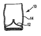
도면을 참조하면, 부품들이 몇몇의 도면에서 유사한 부호로 라벨링되었고, 처음에 도 1-7에서 스텐트리스(stentless) 생물성 인공삽입물의 다수의 변이형들이 도시되어 있다. 특히, 도 1에 "프리스타일 생물성 인공삽입물"로서 Medtronic, Inc.로부터 상업적으로 입수가능한 대동맥 기저부 생물성 인공삽입물(10)이 도시되었다. 이러한 형태의 다른 인공삽입물들은 보통 스텐트리스 인공삽입물로 지칭되는데, 인간 생리학에 가깝고, 생리적 플로우(physiologic flow)를 생성하고, 천연 대동맥 판막의 성능에 근접하도록 디자인된다. 도시된 바와 같이, 생물성 인공삽입물(10)은 하나의 말단에서 튜브 에지(tube edge) 상에 피복재를 구비한 외부 관 모양 모양을 포함하는데 피복재는 노출된 모든 돼지 심근(myocardium)을 커버링하도록 제공된다. 피복재는 예를 들어, 폴리에스테르로 만들어질 수 있다. 본원에 기술된 생물성 인공삽입물(10) 및 다른 생물성 인공삽입물들은 그것들의 내부 관 모양 영역 내에 위치된 하나 이상의 이동가능한 첨판들을 포함한다. 다수의 구현예들에서, 생물성 인공삽입물은 두 개 또는 세 개의 첨판들을 구비한다; 그러나, 오직 하나의 첨판이 제공되고/제공되거나 생물성 인공삽입물이 세 개 이상의 첨판들을 포함하는 것이 가능하다. 도 2 및 3은 각각 생물성 인공삽입물(10)의 정면도 및 단면도이다. 생물성 인공삽입물(10)은 다수의 첨판들(12)이 팽창되는 내부 벽을 구비한 외부 관부(14)를 포함한다. 이러한 생물성 인공삽입물(10)은 환자들의 전체의 천연 대동맥 기저부 및 판막을 대체하기 위한 외과 수술 방법에 사용된다. Referring to the figures, the parts have been labeled with like reference numerals in some of the figures, and initially several variations of the stentless biological prosthesis are shown in FIGS. 1-7. In particular, FIG. 1 shows an aortic base bioprosthesis 10 commercially available from Medtronic, Inc. as a “freestyle bioprosthesis”. Other implants of this type are commonly referred to as stentless prostheses, which are designed to be close to human physiology, produce physiologic flow, and approximate the performance of natural aortic valves. As shown, the
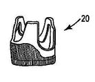
도 4 및 5는 각각 스텐트리스 생물성 인공삽입물(20)의 대안적인 배열의 정면도 및 단면도로서, 특정 환자에 대하여 서로 다른 환자 요구들 및 외과 의사의 선호도가 가장 적합한 생물성 인공삽입물을 선택하는데 고려될 수 있다는 것이 이해되어야 한다. 생물성 인공삽입물(20)은 다중 판막들(22)이 팽창되는 내부 벽을 구비한 외부 관부(24)를 포함한다. 생물성 인공삽입물(20)은 "Prestyled Freestyle Complete Subcoronary Bioprosthesis" 로 칭해질 수 있고, 관상 동맥이 아닌 시너스(noncoronary sinus), 우관상 동맥 시너스(right coronary sinus) 및 좌관상 동맥 시너스(left coronary sinus)에 대한 스캘럽들(scallops)이 있다. 4 and 5 are front and cross-sectional views of alternative arrangements of
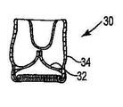
도 6 및 7은 각각 다른 대안적인 스텐트리스 생물성 인공삽입물(30)의 배열에 대한 정면도 및 단면도로서, "Prestyled Freestyle Modified Subcoronary Bioprosthesis"로 칭해진다. 생물성 인공삽입물(30)은 다중 판막들(32)이 팽창되는 내부 벽을 구비한 외부 관부(34)를 포함한다. 이러한 생물성 인공삽입물(30)은 오로지 우관상 동맥 및 좌관상 동맥 시너스들에 대한 스캘럽들을 포함한다. 이러한 생물성 인공삽입물들은 표준 외과 수술법을 사용하여 전형적으로 이식가능한데, 봉합선들을 사용하지 않고 이식하기 위해 본원에 기술된 기법들 및 시스템들에 의해 사용될 수 있다. 6 and 7 are front and cross-sectional views of an arrangement of another alternative
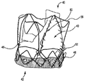
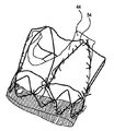
도 8 및 9는 각각 스텐트 프레임(50) 내에 위치된 스텐트리스 생물성 인공삽입물(40)의 정면도 및 사시도이다. 생물성 인공삽입물(40)은 유입단부(42), 유출단부(43), 세 개의 접합선 팽창부들(44) 및 인접한 한 쌍의 팽창부들(44) 사이에 스캘럽 또는 스캘럽된 영역(scalloped area)(46)을 포함한다. 생물성 인공삽입물(40)은 또한, 폴리에스테르 원단과 같은 재료(48)를 추가로 포함하여 생물성 인공삽입물의 유입단부(42)의 적어도 일부를 커버링한다. 도시된 바와 같이, 재료(48)는 생물성 인공삽입물(40)의 외부 표면과 스텐트(50)를 형성(make up)하는 와이어들의 내부 표면 사이에 위치된다. 이어서 재료(48)는 생물성 인공삽입물(40)의 에지 또는 단부 위 및 그것의 관 모양 표면 안으로 팽창한다. 재료(48)는 이러한 내부 관 모양 표면의 벽의 원하는 거리를 따라 팽창할 수 있다. 스텐트(50)는 일반적으로 관 모양 모양으로 배열된 와이어 시리즈를 포함하고, 특히 유입단(42)에서 주변 둘레로 팽창되는 다이아몬드 형상 구조물들(52)을 포함한다. 스텐트(50)는 스텐트(50)의 길이를 따라 종축으로 연장되는 다수의 U-형상 또는 V-형상 구조물들을 포함한다. 구조물들(54)은 구조물들(52)의 피크로부터 일반적으로 연장되는 말단을 구비한다. 인접한 구조물들(54)은 추가적인 지지 와이어들(56)에 의해 그것들의 각각의 피크에서 또는 이에 근접하여 서로에 대하여 연결될 수 있다. 8 and 9 are front and perspective views, respectively, of the
본 발명에 따르면, 각각의 접합선 팽창부들(44)은 스티치를 구비한 V-형상 구조물(54)에 부착되는데, 스티치들은 서로에 대하여 이격되고 각각의 구조물(54)의 양 측면 및 피크를 따라 연장된다. 스티칭(stitching)은 표준 봉합선 재료를 사용하여 수행될 수 있는데, 예를 들어, 각 구조물(54)의 하나의 말단에서 종결될 수 있는 제 1의 말단 및 동일한 구조물(54)의 다른 말단에서 종결될 수 있는 제 2의 말단을 갖는다. 대안으로, 서로 다른 스티칭 패턴이 사용될 수 있다. 도시된 바와 같이, 생물성 인공삽입물(40)은 그것의 유입단(42)에서 피복재(48) 및/또는 배관 재료를 다이아몬드 형상 구조물(52)로 지그재그 패턴으로 봉합하는 것에 의해 스텐트 프레임(50)으로 부가적으로 고정된다. 이러한 도면들이 단지 구조물들(52)의 각각의 하부 또는 에지들을 따라 스티칭하는 것으로 도시되었지만, 유입단(42)은 구조물들(52)의 상부 또는 에지를 따라 스티칭함으로써 부가적으로 고정될 수 있다. 그러나, 임의의 적용에 있어서, 도 8 및 9에 도시된 스티칭 패턴은 판막 고리의 지지를 제공하기에 충분할 수 있다. According to the invention, each
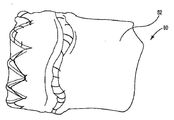
도 10 및 11은 각각 다른 스텐트형 판막(60)의 측면도 및 사시도로서, 도 8 및 9에서 상술된 스텐트 프레임(50)으로서 그것의 스텐트에 대하여 동일하거나 서로 다른 구조물을 사용할 수 있다. 대안으로, 서로 다른 스텐트 구조물이 사용될 수 있다. 어떤 경우에, 스텐트형 판막은 예를 들어, 소 목정맥을 포함할 수 있는 튜브 재료(62)에 의해 둘러싸인 스텐트 프레임(이러한 도면들에서 가시적이지 않음)을 포함한다. 즉, 튜브 재료(62)는 스텐트 프레임의 외부상에 위치된다. 이러한 경우에, 돼지의 첨판들은 튜브 재료(62)의 내부 영역 내에 위치될 수 있다. 튜브 재료(62)는 스텐트 프레임의 다이아몬드-형상 구조물들의 하부를 따라 스티칭하고/스티칭하거나 다른 위치에서 부품들을 서로에 대하여 스티칭함으로써 스텐트 프레임에 부착될 수 있다. 돼지의 첨판들과 같은 첨판들을 직접 스텐트로 부착하는 것을 사용하는 대신에 이러한 스텐트에 대한 튜브 재료의 부착은 돼지의 첨판들로부터 튜브/스텐트 구조물로의 생리적 박동형 하중 조건들에 기인하여 장기 구조물적 피로를 이동할 수 있다. 이는 잠재적으로 조직 판막 첨판들의 기능적인 수명을 증가시킬 수 있다. 10 and 11 are side and perspective views, respectively, of different stent-
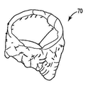
도 12에 소 목정맥 조직을 커버링하는 스텐트를 포함하는 팽창가능한 스텐트형 판막(70)에 대한 다른 구현예가 도시되었다. 돼지의 조직은 첨판들이 와이어 스텐트 프레임과 직접 접촉하는 것으로부터 보호하기 위해 정맥 조직 내에 부착된다. 도시된 바와 같이, 조직은 스텐트 프레임의 일부분을 따라서 스티칭을 통해 스텐트에 부착된다. 서로 다른 스티칭 배치들이 대안적으로 사용될 수 있다. Another embodiment is shown in FIG. 12 for an
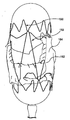
도 13에 다른 예시적인 스텐트 프레임(100)이 도시되었는데, 도 1-7에 도시된 생물성 인공삽입물의 임의의 하나와 같은 스텐트리스 생물성 인공삽입물이 여기에 부착될 수 있다. 스텐트는 맨드릴 상에 도시되어 정면 와이어들이 보다 명확하게 보일 수 있다. 스텐트(100)는 예를 들어, 니티놀과 같은 자기-팽창 재료로 만들어질 수 있거나 배치될 수 있어 팽창 풍선에 의해 제공되는 힘의 인가에 의해 팽창가능하다. 이러한 스텐트(100)는 서브-관상 동맥 스텐트(예를 들어, 25 mm 길이)로 칭해질 수 있을 만큼 충분히 짧게 크기화되어 스텐트를 대동맥 내의 관상 동맥 아래에 배치하는 것이 가능하다. Another
일 구현예에서, 스텐트(100)는 일반적으로 관 모양이고 다중의 종방향 또는 수직방향 와이어들(102)를 포함하는데, 이들은 스텐트의 종축들(104)에 대하여 일반적으로 평행하게 연장된다. 와이어들(102)은 일반적으로 스텐트(100)의 관 모양의 주변 둘레로 서로에 대하여 이격된다. 스텐트(100)는 추가로 접합선 부착 포스트(posts)(106)와 같은 특징들을 포함하는데, 여기에서 조직이 부착되어 판막 이내로 스텐트를 만들 수 있다. 접합선 부착 포스트(106)는 각각 두 개의 종 방향 와이어들을 포함할 수 있는데, 종 방향 와이어들은 와이어들(102)이 서로에 대하여 이격되는 것보다 더 가까이 서로에 대하여 이격된다. In one embodiment, the
이러한 구현예에서, 스텐트(100)은 세 개의 접합건 부착 포스트(106)를 포함하는데, 여기에서 각 포스트들(106)은 생물성 인공삽입물(40)의 팽창부들(44)과 같이 생물성 인공삽입물의 접합선 확장부의 하나에 대한 연결 위치로 사용될 수 있다. 대안으로, 세 개의 포스트들(106)보다 더 많거나 더 적은 것이 각각 세 개의 첨판들보다 더 많거나 더 적은 첨판을 구비한 판막에 대하여 제공될 수 있다. 접합선들의 부착에 대한 구조물을 제공하는 것에 더하여, 포스트들(106)은 또한 스텐트(100)로 부가적인 안정성을 제공한다. 스텐트(100)는 또한 다중 V-형상 와이어 구조물들(108)을 한 쌍의 와이어들(102) 사이에 및/또는 와이어(102)와 인접한 부착 포스트(106) 사이에 포함한다. 비록 스텐트(100)가 인접한 수직 와이어 구조물들 사이에서 서로에 대하여 종 방향으로 이격되어 세 개의 이러한 V-형상 와이어들(108)을 구비한 것으로 도시되었지만, 세 개의 V-형상 와이어들보다 더 많거나 더 적은 것이 대신될 수 있다. 와이어들(108) 모두 또는 일부는 스텐트(100)의 외부 관 모양에 대하여 적어도 약간 외부로 향하게 플레어(flared)될 수 있어서 스텐트가 환자 내에 이식될 때 천연 첨판들을 포획하는데 사용될 수 있는 통합된 플랜지 구조물들을 생성한다. In this embodiment, the
부가적인 와이어 구조물들(122)이 스텐트(100)의 하나의 말단(120)에 위치되었는데, 일반적으로 V-형상이고, 와이어들(108)의 피크들과 일반적으로 동일한 방향으로 배향된 각각의 "V" 구조물들의 피크를 갖는다. 와이어 구조물들(122) 모두 또는 일부는 또한 스텐트(100)의 외부 관 모양에 대하여 적어도 약간 외부로 향하게 플레어될 수 있다. 다양한 와이어 구조물들이 스텐트의 관형 외부 모양에 대하여 확장되는 지점의 양 및 각도는 환자 고유의 해부학적 특징들을 포획하도록 선택될 수 있다. 부가적으로, 와이어 구조물들(122)의 플레어는 임플란트와 천연 고리들 사이의 누출을 방지하거나 최소화하는데 사용되고/사용되거나 예를 들어, 스텐트(100)를 심장 내의 개구부의 벽에 대하여 고정하여 스텐트의 이동을 방지하도록 물리적 및/또는 가시적 도킹 특징(docking feature)을 제공하는데 사용된다.
와이어들(102) 및 포스트들(106)의 전부 또는 일부의 하나의 말단은 추가로 루프(loop) 또는 아이릿(eyelet)(126)을 포함하는데, 이들은 예를 들어, 이송 시스템 및/또는 조직 판막에 부착하도록 사용될 수 있다. 단일 측면 아이릿 부착 말단은 예를 들어, 전방 및 후당 절차 모두에서 재쉬스가능한(resheathable) 이송 시스템에 사용될 수 있다. One end of all or part of the
스텐트의 이러한 구현예는 간격들 또는 개구들(110)을 포함하는데, 이들은 부착 포스트들(106)을 형성하는 두 개의 와이어들 사이의 평행의 부재들(112)의 사용에 의해 생성된다. 이러한 개구들(110)은 위치들을 제공하는데, 이 위치들을 통해서 봉합 재료들, 바늘들 및/또는 다른 패스닝 재료들이 스텐트 프레임에 대한 생물성 인공삽입물의 부착을 위해 삽입될 수 있다. 부가적으로, 평행 부재들(112)이 패스닝 재료들에 대한 한정된 앵커링 위치들로 사용될 수 있다. 예를 들어, 봉합 재료는 제 1의 개구(110)을 통해 삽입될 수 있고, 이어서 다른 개구(110)를 통해 예정된 패턴으로 생물성 인공삽입물의 접합성 팽창부들에 대하여 판막 재료를 스티치한다. 평행 부재들(112)은 추가로 봉합선들 또는 다른 부착 메커니즘의 수직 이동을 제한하는 앵커링 구조물들로서 사용될 수 있다. 생물성 인공삽입물의 다른 영역을 스텐트(100)로 부착하기 위해서, 생물성 인공삽입물(40)에 대하여 상술된 바와 같이 스캘럽된 영역들은 예를 들어, 특정한 모양의 와이어들(108) 및/또는 수직 와이어들(102)을 따르는 것과 같이 스텐트(100)의 선택된 와이어들을 따라서 스티치될 수 있다. 다수의 시스템들, 부품들 및 장치들이 스텐트 구조물의 내부 영역 내에 판막 재료(예를 들어, 조직 첨판들)를 부착하도록 하기 기술된다. 이러한 목적을 위해 본원에 도시되고 기술된 시스템들이 상술된 스텐트 구성들 및/또는 다른 스텐트 구조물들과 함께 사용될 수 있다는 것이 이해되어야 한다. This embodiment of the stent includes gaps or
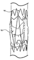
도 18에 다른 예시적인 스텐트 프레임(130)이 도시되었는데, 여기에 도 1-7에 도시된 생물성 인공삽입물의 임의의 하나와 같은 스텐트리스 생물성 인공삽입물이 부착될 수 있다. 이러한 텐트 프레임(tent frame)(130)은 맨드릴 상에 도시되어 정편 와이어들이 보다 명확하게 보일 수 있다. 스텐트(130)는 수프라-관상 동맥 스텐트(supra-coronary stent)로 칭해질 수 있을 만큼 충분히 크고 길게 크기화되어 그것을 대동맥 내의 관상 동맥 상부로 연장하도록 배치시킬 수 있다. 스텐트(130)는 적어도 하나의 종 방향 포스트(132)를 포함하는데, 종 방향 포스트(132)는 스텐트(130)의 고리 영역을 따라서 일반적으로 연장되고 첨판 재료의 부착을 수용하는 높이를 갖는다. 이러한 스텐트(130)에 의해, 와이어 구조물은 포스트(132)의 하나의 말단과 스텐트의 제 1의 말단(134)(스텐트의 대동맥 면으로 칭해질 수 있음) 사이에서 연장되고, 부가적인 와이어 구조물은 포스트(132)의 다른 말단과 스텐트의 제 2의 말단(136)(스텐트의 심실면으로 칭해질 수 있음) 사이에서 연장된다. 스텐트(130)는 생물성 인공삽입물의 각각의 접합선 팽창부에 대하여 하나의 종 방향 포스트(132)를 포함할 수 있는데, 원하는 경우에 여기로 스텐트(130)가 부착된다. 즉, 세 개의 첨판 생물성 인공삽입물에 대하여, 세 개의 포스트들(132)이 제공될 수 있다. Another
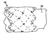
도 19에 스텐트 프레임(140)의 다른 구현예가 도시되었는데, 여기에 도 1-7에 도시된 생물성 인공삽입물의 임의의 하나와 같은 스텐트리스 생물성 인공삽입물이 부착될 수 있다. 스텐트(140)는 그것의 길이를 따라 일반적으로 규칙적인 대각선의 많은 선이 교차하는 십자형 패턴으로 배열된 와이어 구조물을 포함한다. 스텐트(140)는 하나의 말단에 와이어들에 대한 구상(bulbous) 모양을 추가로 포함한다. 생물성 인공삽입물의 접합선 팽창부들은 스텐트(140)의 특정 와이어들에 부착되어 부품들을 서로에 대하여 고정적으로 부착시킬 수 있다. Another embodiment of
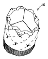
도 14 및 15에 도 10 및 11에 대하여 상술된 바와 같이 소 목정맥 또는 튜브 커버로 만들어진 판막(190)의 다른 구현예가 도시되었다. 관형 조직 덮개는 하나의 말단에 관형 조직 팽창부(192)를 포함하여 부가적인 앵커링 특징을 제공하여 봉합선이 없는 외과 이식술에 대하여 이동하는 것을 방어한다. 조직 팽창부(102)는 스텐트의 유출 측면상에 위치되고, 대동맥 판막 대체를 위한 대동맥절개술 봉합 안으로 통합될 수 있다. 대안으로 그것은 폐동맥 판막 대체 절차들에서 폐동맥 및/또는 우심실 유출 관 복원을 위하여 사용될 수 있다. 대동맥 판막 대체에 대한 판막(190)을 사용하기 위해, 윈도우들(windows)은 스텐트의 시너스 영역 내에서 튜브 안으로 절개되어 방해받지 않는 관상 동맥 흐름을 허용할 필요가 있다. 14 and 15, another embodiment of the
이러한 구현예에서, 튜브 덮개(예를 들어, 소 목정맥 부위)는 스텐트의 외표면 위로 위치되고, 이어서 판막이 스텐트의 내부 영역 내에 위치된다. 단일 봉합선은 판막의 근위단 및 소 목정맥 모두를 스텐트의 근위 크라운(crowns)으로 고정시킨다. 판막 접합선들 및 원위 소 튜브는 예를 들어, 조직을 고정하고 첨판 접착을 유지하도록 요구되는 지점에서 중단된 안티-해머킹(anti-hammocking) 스티치들에 의해 스텐트 셀들로 고정된다. In this embodiment, the tube sheath (eg, the bovine venous region) is positioned over the outer surface of the stent, and then the valve is located in the inner region of the stent. A single suture secures both the proximal end of the valve and the bovine venous vein to the proximal crowns of the stent. The valve seams and distal bovine tubes are secured to the stent cells, for example by interrupted anti-hammocking stitches at the points required to fix the tissue and maintain leaflet adhesion.
본원에 도시되고 기술된 스텐트의 다양한 구현예들에서, 스텐트의 특정 부분들의 영상비가 도시된 것들과는 약간 상이할 수 있다는 것을 알아야 한다. 또한, 본원에 도시된 스텐트 구현예들은 다수의 구현예들에 기술된 수직 스텐트 포스트들과 같이 판막에 대한 조직의 부착들 위해 부가적인 구조물을 포함하도록 변경될 수 있다. In various implementations of the stent shown and described herein, it should be appreciated that the aspect ratio of certain portions of the stent may differ slightly from those shown. In addition, the stent embodiments shown herein may be modified to include additional structures for attachment of tissue to the valve, such as the vertical stent posts described in many embodiments.
도 16 및 17에 스텐트가 도시되었는데, 여기에 생물성 인공삽입물이 트랜스카데터 이송 방법을 사용한 이식을 위해 부착된다. 특히, 도 16에 스텐트(150) 및 부착된 생물성 인공삽입물(160)이 도시되었는데, 그것의 각각은 그 내부에 적어도 부분적으로 압축된 구성을 갖는다. 도 17에 풍선-형태 이송 시스템에 의해 적어도 부분적으로 팽창된 스텐트(150) 및 생물성 인공삽입물(160)이 도시되었다. 도시된 구현예에서, 생물성 인공삽입물(160)은 스캘럽된 개구들 또는 영역들(162)을 포함하는데, 이들은 생물성 인공삽입물과 관상 동맥들 사이에서 유체 유동을 허용하도록 위치될 수 있다. 스캘럽된 개구들(162)은 생물성 인공삽입물의 접합선 팽창부들(164) 사이에 각각 위치된다. Stents are shown in FIGS. 16 and 17, where a bioprosthesis is attached for implantation using the transcatheter transfer method. In particular,
생물성 인공삽입물(160)의 각각의 스캘럽된 개구들(162)의 에지를 따른 지점들은 특정한, 미리 결정된 스텐트의 와이어들에 부착된다. 도시된 구현예에서, 스텐트(150)는 스텐트(150)의 중심축에 대하여 종 방향으로 연장된 상대적으로 좁은 V-형상 구조물들(152) 안으로 배열된 다수의 와이어들을 포함한다. 이러한 구현예에서, 스텐트(150)에 V-형상의 하나의 구조물(152)가 제공되어 각각의 접합선 팽창부(164)에 대응되고, 하나의 V-형상 구조물은 팽창부들(164)(예를 들어, 스캘럽된 영역들(162)) 사이의 각각의 영역에 대응된다. 생물성 인공삽입물을 스텐트에 부착하는데 사용된 스티칭 패턴은 V-형상 구조물들을 따라 미끄러질 수 있는 스티치들을 제공하는 것을 포함하여 생물성 인공삽입물이 압축되고 팽창되는 동안 서로에 대하여 부품들이 이동하도록 허용하고, 스텐트 및 그것이 부착된 생물성 인공삽입물의 필요한 치수 변화들을 허용한다. 스텐트 와이어들을 따르는 스티치들의 이러한 이동은 장치의 압축 및/또는 팽창이 일어나는 동안 부품들이 재배치될 때 더 작은 가능한 이동 범위를 갖는 스티치들 상에 위치될 수 있는 응력들(stresses)을 방지하거나 최소화한다. Points along the edge of each scalloped opening 162 of
본 발명의 풍선-팽창가능한 스텐트의 이식 부위로의 이송은 경피적으로 수행될 수 있다. 일반적으로, 이는 이송 카데터, 풍선 카데터 및 가이드 와이어를 포함하는 트랜스카데터 조립체를 제공하는 것을 포함한다. 이러한 유형의 임의의 이송 카데터들은 본 발명이 속하는 분야에 잘 알려져 있고, 풍선 카데터가 수용되는 루멘(lumen)을 규정한다. 풍선 카데터는, 차례로 루멘을 규정하는데, 이 내부에서 가이드 와이어가 미끄러질 수 있도록 배치된다. 또한, 풍선 카데터는 팽창 소스에 유동적으로 연결된 풍선을 포함한다. 만일 이식된 스텐트가 자가-팽창 형태의 스텐트이면, 풍선은 필요하지 않고, 본원에 기술된 바와 같이 스텐트가 전개될때 까지 쉬스 또는 다른 제한 도구들이 스텐트를 그것의 압축 상태로 유지하는데 사용된다. 임의의 경우에, 도 16 및17의 스텐트(150)와 같이 풍선-팽창가능한 스텐트에 대하여 트랜스카데터 조립체는 이식 부위로의 원하는 경피적인 접근을 위해 적절하게 크기화된다. 예를 들어, 트랜스카데터 조립체는 목동맥, 목정맥, 쇄골하정맥, 대퇴동맥 또는 정맥 또는 이들과 유사한 곳에서 개구를 통해 심장 판막을 이송하도록 크기화될 수 있다. 필수적으로 임의의 경피적 늑간 침투가 트랜스카데터 조립체의 이용을 용이하게 하기 위해 이뤄질 수 있다. Transfer of the balloon-expandable stent of the invention to the implantation site can be performed transdermally. Generally, this includes providing a transcatheter assembly that includes a transfer catheter, a balloon catheter, and a guide wire. Any transport catheter of this type is well known in the art and defines the lumen in which balloon catheter is accommodated. The balloon catheter, in turn, defines the lumen, which is arranged to allow the guide wire to slide therein. The balloon catheter also includes a balloon fluidly connected to the inflation source. If the implanted stent is a self-expanding stent, a balloon is not needed and a sheath or other limiting tool is used to keep the stent in its compressed state until the stent is deployed as described herein. In any case, for balloon-expandable stents, such as
이송되기 이전에, 스텐트는 스텐트 구조물의 영구적인 변형을 일으키지 않고 수축된 상태에서 풍선 위에 가능한 작게 장착된다. 확장된 상태에 비하여, 지지 구조물은 그것 위에서 및 풍선 위에서 압축되고, 따라서, 팽창된 상태에서의 내부 직경에 비하여 감소된 내부 직경을 규정한다. 이러한 기재가 풍선-팽창가능한 스텐트의 이송에 대한 것이지만, 동일한 기본적인 절차들이 또한 자가-확장 스텐트에 대하여 적용될 수 있는데, 여기에서 이송 시스템은 풍선 및 그것의 팽창부를 필수적으로 포함하지 않지만, 바람직하게는 압축된 상태에서 그것이 전개되도록 해제될 때까지 스텐트를 유기하기 위한 쉬스 또는 다른 형태의 구성을 포함한다. Prior to being transported, the stent is mounted as small as possible on the balloon in its retracted state without causing permanent deformation of the stent structure. In comparison to the expanded state, the support structure is compressed on and above the balloon, thus defining a reduced internal diameter compared to the internal diameter in the expanded state. Although this substrate is for the transport of a balloon-expandable stent, the same basic procedures can also be applied for a self-expansion stent, wherein the transport system does not necessarily include the balloon and its inflation, but is preferably compressed And a sheath or other form of configuration for retracting the stent until it is released to unfold in a closed state.
풍선에 장착된 스텐트에 의해, 트랜트카데터 조립체는 경피적 개구(미도시)를 통해 이송 카데터에 의해 환자 내로 이송된다. 이식 부위는 가이드 와이어를 환자 내로 삽입하는 것에 의해 위치되는데, 가이드 와이어는 이송 카데터의 원위단으로부터 연장되고, 그렇지 않으면 풍선 카데터에 의해 이송 카데터의 내부로 수축된다. 풍선 카데터는 이어서 이식 부위에 대하여 위치된 풍선 및 스텐트에 의해 가이드 와이어를 따라 이송 카데터로부터 원위 방향으로 전진한다. 대안의 구현예에서, 스텐트는 최소 침습적 외과 수술 절개(즉, 비-경피적으로)를 통해 이식 부위로 이송될 수 있다. 다른 대안적인 구현예에서, 스텐트는 개방 심장/가슴 외과수술을 통해 이송된다. 본 발명에 의한 스텐트의 일 구현예에서, 스텐트는 방사선, 에코제닉(echogenic) 또는 MRI 가시 재료를 포함하여 스텐트의 적절한 배치의 시각적 확인을 용이하게 한다. 대안적으로 다른 알려진 외과적인 시각적 지원들이 스텐트 안으로 통합될 수 있다. 심장 내에서 스텐트의 배치에 대하여 기술된 기법들이 그것이 위치된 해부학적 구조물의 길이에 대하여 종 방향으로 스탠트의 배치를 모니터링하고 배치하도록 사용될 수 있다. With the stent mounted to the balloon, the transcatheter assembly is transferred into the patient by a transfer catheter through a percutaneous opening (not shown). The implant site is located by inserting a guide wire into the patient, which guide wire extends from the distal end of the transfer catheter, or is otherwise retracted into the transfer catheter by the balloon catheter. The balloon catheter is then advanced distally from the transfer catheter along the guide wire by a balloon and stent positioned relative to the implantation site. In alternative embodiments, the stent may be transferred to the implant site via a minimally invasive surgical incision (ie, non-dermally). In another alternative embodiment, the stent is transferred via open heart / chest surgery. In one embodiment of the stent according to the present invention, the stent includes radiation, echogenic or MRI visible materials to facilitate visual identification of the proper placement of the stent. Alternatively other known surgical visual supports can be incorporated into the stent. Techniques described for placement of the stent within the heart can be used to monitor and place the placement of the stent in the longitudinal direction relative to the length of the anatomical structure in which it is located.
일단 스텐트가 적절하게 위치되면, 풍선 카데터는 풍선을 팽창시키도록 작동되고, 따라서 스텐트를 팽창된 상태로 변화시킨다. Once the stent is properly positioned, the balloon catheter is operated to inflate the balloon, thus changing the stent to the expanded state.
대안적으로, 지지체 구조물가 형상 기억 재료로 구성되는 경우, 스텐트는 외부력들(예를 들어, 쉬스)을 제거함으로써 그것의 팽창된 위치로 팽창하도록 허용될 수 있다. Alternatively, if the support structure is composed of shape memory material, the stent may be allowed to expand to its expanded position by removing external forces (eg, sheath).
본 발명은 몇몇의 구현예들을 참조하여 설명되었다. 상술된 설명 및 예시들은 단지 명확한 이해를 위해 주어진 것이다. 이들에 대한 어떠한 불필요한 제한도 있어서는 않된다. 본 발명이 속하는 당업자들에게 있어서, 본 발명의 범위를 벗어나지 않고 기술된 구현예들에 대한 다양한 변경이 이뤄질 수 있다는 것이 명백하다. 따라서, 본 발명의 범위는 본원에 기술된 구조물들에 제한되어서는 안되고, 청구범위에 기재된 언어 및 이러한 구조물들의 동등물들에 의해 기술된 구조물들에 의한다. The invention has been described with reference to several embodiments. The foregoing description and examples are given for clarity of understanding only. There should be no unnecessary restrictions on these. It will be apparent to those skilled in the art that various changes may be made to the described embodiments without departing from the scope of the invention. Thus, the scope of the present invention should not be limited to the structures described herein, but rather by the structures described by the language described in the claims and their equivalents.
Claims (13)
스텐트 구조물의 관형 본체부의 내부 영역 내에 적어도 부분적으로 위치된 생물성 인공삽입물 판막(bioprosthetic valve)을 포함하는 스텐트형 판막(stented valve)으로서, 상기 생물성 인공삽입물 판막은
적어도 두 개의 접합선 팽창부들 및 다수의 첨판들이 연장되는 내부 벽을 포함하는 외부 관부(outer tubular portion) 및
인접한 접합선 팽창부들 사이에서 연장되는 하나 이상의 스캘럽부(scalloped portion)를 포함하고, 상기 적어도 두 개의 접합선 팽창부들은 스텐트 구조물을 따라 미끄러질 수 있는 부착 재료에 의해 스텐트 구조물에 고정되어 스텐트 구조물의 종축을 따라 스텐트 구조물에 대한 판막의 자유 이동을 허용하는 것을 특징으로 하는 스텐트형 판막.
A compressible and expandable stent structure comprising a tubular body portion having an interior region and a longitudinal axis; And
A stented valve comprising a bioprosthetic valve at least partially located within an interior region of the tubular body portion of the stent structure, wherein the bioprosthetic valve is
An outer tubular portion comprising at least two seam expansions and an inner wall from which a plurality of leaflets extend;
One or more scalloped portions extending between adjacent seam expansions, wherein the at least two seam expansions are secured to the stent structure by an attachment material that can slide along the stent structure and along the longitudinal axis of the stent structure. A stent valve, characterized in that it allows free movement of the valve relative to the stent structure.
The stent valve of claim 1, wherein each of the one or more scallops is secured to the stent structure.
The stent valve of claim 1, wherein each of the one or more scallops is designed to match a coronary artery when implanted into the aorta of a patient.
The stent valve of claim 2, wherein the scallops are sutured with the stent structure to slide against the stent structure.
The stent valve of claim 1, wherein the stent structure is self-expandable from a compressed state to an expanded state by removal of an external compressive force.
The stent valve of claim 1, wherein the stent structure is expandable from a compressed state to an expanded state by applying an external expansion force.
The stent valve of claim 1, wherein the outer tubular portion of the bioprosthetic valve includes three seam expansions.
8. The stent valve of claim 7, wherein the bioprosthetic valve comprises three leaflets.
상기 스텐트 구조물의 외부 표면을 적어도 부분적으로 커버링하고 상기 스텐트 구조물의 유출단을 넘어서 연장되는 관형 조직 재료(tubular tissue material); 및
스텐트의 내부 영역에 부착된 다수의 첨판들을 포함하는 스텐트형 판막(stented valve).
A compressible and expandable stent structure comprising a tubular body portion comprising an inner region, an outer surface, a longitudinal axis, an inflow end and an outflow end;
Tubular tissue material at least partially covering the outer surface of the stent structure and extending beyond the outlet end of the stent structure; And
Stented valve comprising a plurality of leaflets attached to the inner region of the stent.
10. The stent valve of claim 9, wherein the tubular tissue material comprises bovine venous veins.
10. The stent valve of claim 9, wherein the tubular tissue material includes one or more apertures to permit uninterrupted flow of fluid.
The stent valve of claim 10, wherein the stent valve includes an opening in each sinus region of the tubular tissue material to allow uninterrupted flow of coronary fluid.
Applications Claiming Priority (2)
| Application Number | Priority Date | Filing Date | Title |
|---|---|---|---|
| US12/476,702 | 2009-06-02 | ||
| US12/476,702 US8075611B2 (en) | 2009-06-02 | 2009-06-02 | Stented prosthetic heart valves |
Publications (1)
| Publication Number | Publication Date |
|---|---|
| KR20120020189A true KR20120020189A (en) | 2012-03-07 |
Family
ID=42562549
Family Applications (1)
| Application Number | Title | Priority Date | Filing Date |
|---|---|---|---|
| KR1020117031714A KR20120020189A (en) | 2009-06-02 | 2010-06-02 | Stented prosthetic heart valves |
Country Status (8)
| Country | Link |
|---|---|
| US (5) | US8075611B2 (en) |
| EP (1) | EP2437687B1 (en) |
| JP (1) | JP5490228B2 (en) |
| KR (1) | KR20120020189A (en) |
| CN (1) | CN102497836B (en) |
| AU (1) | AU2010256630B2 (en) |
| SG (1) | SG176608A1 (en) |
| WO (1) | WO2010141626A2 (en) |
Cited By (1)
| Publication number | Priority date | Publication date | Assignee | Title |
|---|---|---|---|---|
| KR20190099289A (en) * | 2016-12-28 | 2019-08-26 | 상하이 마이크로포트 카디오플로우 메디테크 컴퍼니 리미티드 | Artificial valve |
Families Citing this family (217)
| Publication number | Priority date | Publication date | Assignee | Title |
|---|---|---|---|---|
| US7381220B2 (en) * | 2000-09-20 | 2008-06-03 | Ample Medical, Inc. | Devices, systems, and methods for supplementing, repairing, or replacing a native heart valve leaflet |
| DK1450727T3 (en) | 2001-10-04 | 2010-10-18 | Neovasc Medical Ltd | Power reducing implant |
| IL158960A0 (en) | 2003-11-19 | 2004-05-12 | Neovasc Medical Ltd | Vascular implant |
| DE102005003632A1 (en) | 2005-01-20 | 2006-08-17 | Fraunhofer-Gesellschaft zur Förderung der angewandten Forschung e.V. | Catheter for the transvascular implantation of heart valve prostheses |
| US7914569B2 (en) | 2005-05-13 | 2011-03-29 | Medtronics Corevalve Llc | Heart valve prosthesis and methods of manufacture and use |
| US8092520B2 (en) | 2005-11-10 | 2012-01-10 | CardiAQ Technologies, Inc. | Vascular prosthesis connecting stent |
| WO2008013915A2 (en) | 2006-07-28 | 2008-01-31 | Arshad Quadri | Percutaneous valve prosthesis and system and method for implanting same |
| US8414643B2 (en) | 2006-09-19 | 2013-04-09 | Medtronic Ventor Technologies Ltd. | Sinus-engaging valve fixation member |
| US11304800B2 (en) | 2006-09-19 | 2022-04-19 | Medtronic Ventor Technologies Ltd. | Sinus-engaging valve fixation member |
| US8834564B2 (en) | 2006-09-19 | 2014-09-16 | Medtronic, Inc. | Sinus-engaging valve fixation member |
| US10624621B2 (en) | 2006-11-07 | 2020-04-21 | Corvia Medical, Inc. | Devices and methods for the treatment of heart failure |
| US9232997B2 (en) * | 2006-11-07 | 2016-01-12 | Corvia Medical, Inc. | Devices and methods for retrievable intra-atrial implants |
| US10413284B2 (en) | 2006-11-07 | 2019-09-17 | Corvia Medical, Inc. | Atrial pressure regulation with control, sensing, monitoring and therapy delivery |
| US20110257723A1 (en) | 2006-11-07 | 2011-10-20 | Dc Devices, Inc. | Devices and methods for coronary sinus pressure relief |
| US7896915B2 (en) | 2007-04-13 | 2011-03-01 | Jenavalve Technology, Inc. | Medical device for treating a heart valve insufficiency |
| DE102007034363A1 (en) * | 2007-07-24 | 2009-01-29 | Biotronik Vi Patent Ag | endoprosthesis |
| DE202008018589U1 (en) | 2007-09-26 | 2016-03-14 | St. Jude Medical, Inc. | Foldable heart valve prostheses |
| US9532868B2 (en) | 2007-09-28 | 2017-01-03 | St. Jude Medical, Inc. | Collapsible-expandable prosthetic heart valves with structures for clamping native tissue |
| EP4079261A1 (en) | 2007-12-14 | 2022-10-26 | Edwards Lifesciences Corporation | Leaflet attachment frame for a prosthetic valve |
| JP5687070B2 (en) | 2008-01-24 | 2015-03-18 | メドトロニック,インコーポレイテッド | Stent for prosthetic heart valve |
| WO2009094197A1 (en) * | 2008-01-24 | 2009-07-30 | Medtronic, Inc. | Stents for prosthetic heart valves |
| US8157852B2 (en) | 2008-01-24 | 2012-04-17 | Medtronic, Inc. | Delivery systems and methods of implantation for prosthetic heart valves |
| WO2011104269A1 (en) | 2008-02-26 | 2011-09-01 | Jenavalve Technology Inc. | Stent for the positioning and anchoring of a valvular prosthesis in an implantation site in the heart of a patient |
| US9044318B2 (en) | 2008-02-26 | 2015-06-02 | Jenavalve Technology Gmbh | Stent for the positioning and anchoring of a valvular prosthesis |
| WO2009149462A2 (en) | 2008-06-06 | 2009-12-10 | Edwards Lifesciences Corporation | Low profile transcatheter heart valve |
| WO2010008548A2 (en) | 2008-07-15 | 2010-01-21 | St. Jude Medical, Inc. | Collapsible and re-expandable prosthetic heart valve cuff designs and complementary technological applications |
| EP2367505B1 (en) | 2008-09-29 | 2020-08-12 | Edwards Lifesciences CardiAQ LLC | Heart valve |
| CA2739275C (en) | 2008-10-01 | 2017-01-17 | Impala, Inc. | Delivery system for vascular implant |
| WO2010098857A1 (en) | 2009-02-27 | 2010-09-02 | St. Jude Medical, Inc. | Stent features for collapsible prosthetic heart valves |
| CA2961053C (en) | 2009-04-15 | 2019-04-30 | Edwards Lifesciences Cardiaq Llc | Vascular implant and delivery system |
| US8075611B2 (en) | 2009-06-02 | 2011-12-13 | Medtronic, Inc. | Stented prosthetic heart valves |
| US9757107B2 (en) | 2009-09-04 | 2017-09-12 | Corvia Medical, Inc. | Methods and devices for intra-atrial shunts having adjustable sizes |
| US20110313515A1 (en) | 2010-06-21 | 2011-12-22 | Arshad Quadri | Replacement heart valve |
| US9730790B2 (en) | 2009-09-29 | 2017-08-15 | Edwards Lifesciences Cardiaq Llc | Replacement valve and method |
| US8449599B2 (en) | 2009-12-04 | 2013-05-28 | Edwards Lifesciences Corporation | Prosthetic valve for replacing mitral valve |
| US8870950B2 (en) | 2009-12-08 | 2014-10-28 | Mitral Tech Ltd. | Rotation-based anchoring of an implant |
| EP2528646A4 (en) | 2010-01-29 | 2017-06-28 | DC Devices, Inc. | Devices and systems for treating heart failure |
| CA2785041A1 (en) | 2010-01-29 | 2011-08-04 | Dc Devices, Inc. | Devices and methods for reducing venous pressure |
| US9226826B2 (en) | 2010-02-24 | 2016-01-05 | Medtronic, Inc. | Transcatheter valve structure and methods for valve delivery |
| US8795354B2 (en) | 2010-03-05 | 2014-08-05 | Edwards Lifesciences Corporation | Low-profile heart valve and delivery system |
| WO2011111047A2 (en) | 2010-03-10 | 2011-09-15 | Mitraltech Ltd. | Prosthetic mitral valve with tissue anchors |
| US8652204B2 (en) | 2010-04-01 | 2014-02-18 | Medtronic, Inc. | Transcatheter valve with torsion spring fixation and related systems and methods |
| US8579964B2 (en) | 2010-05-05 | 2013-11-12 | Neovasc Inc. | Transcatheter mitral valve prosthesis |
| JP2013526388A (en) | 2010-05-25 | 2013-06-24 | イエナバルブ テクノロジー インク | Artificial heart valve, and transcatheter delivery prosthesis comprising an artificial heart valve and a stent |
| US9763657B2 (en) | 2010-07-21 | 2017-09-19 | Mitraltech Ltd. | Techniques for percutaneous mitral valve replacement and sealing |
| US11653910B2 (en) | 2010-07-21 | 2023-05-23 | Cardiovalve Ltd. | Helical anchor implantation |
| US9132009B2 (en) | 2010-07-21 | 2015-09-15 | Mitraltech Ltd. | Guide wires with commissural anchors to advance a prosthetic valve |
| US8992604B2 (en) | 2010-07-21 | 2015-03-31 | Mitraltech Ltd. | Techniques for percutaneous mitral valve replacement and sealing |
| US9039759B2 (en) | 2010-08-24 | 2015-05-26 | St. Jude Medical, Cardiology Division, Inc. | Repositioning of prosthetic heart valve and deployment |
| WO2012040655A2 (en) | 2010-09-23 | 2012-03-29 | Cardiaq Valve Technologies, Inc. | Replacement heart valves, delivery devices and methods |
| DE202011111128U1 (en) | 2010-10-05 | 2020-05-27 | Edwards Lifesciences Corporation | Prosthetic heart valve |
| GB201019354D0 (en) * | 2010-11-16 | 2010-12-29 | Vascutek Ltd | Prothesis |
| US9717593B2 (en) | 2011-02-01 | 2017-08-01 | St. Jude Medical, Cardiology Division, Inc. | Leaflet suturing to commissure points for prosthetic heart valve |
| EP2673038B1 (en) | 2011-02-10 | 2017-07-19 | Corvia Medical, Inc. | Apparatus to create and maintain an intra-atrial pressure relief opening |
| US9155619B2 (en) | 2011-02-25 | 2015-10-13 | Edwards Lifesciences Corporation | Prosthetic heart valve delivery apparatus |
| US9554897B2 (en) | 2011-04-28 | 2017-01-31 | Neovasc Tiara Inc. | Methods and apparatus for engaging a valve prosthesis with tissue |
| US9308087B2 (en) | 2011-04-28 | 2016-04-12 | Neovasc Tiara Inc. | Sequentially deployed transcatheter mitral valve prosthesis |
| US8795357B2 (en) | 2011-07-15 | 2014-08-05 | Edwards Lifesciences Corporation | Perivalvular sealing for transcatheter heart valve |
| CA2841952C (en) | 2011-07-20 | 2018-07-03 | Boston Scientific Scimed, Inc. | Heart valve replacement |
| EP2736456B1 (en) | 2011-07-29 | 2018-06-13 | Carnegie Mellon University | Artificial valved conduits for cardiac reconstructive procedures and methods for their production |
| US8852272B2 (en) | 2011-08-05 | 2014-10-07 | Mitraltech Ltd. | Techniques for percutaneous mitral valve replacement and sealing |
| WO2013021375A2 (en) | 2011-08-05 | 2013-02-14 | Mitraltech Ltd. | Percutaneous mitral valve replacement and sealing |
| WO2013021374A2 (en) | 2011-08-05 | 2013-02-14 | Mitraltech Ltd. | Techniques for percutaneous mitral valve replacement and sealing |
| US20140324164A1 (en) | 2011-08-05 | 2014-10-30 | Mitraltech Ltd. | Techniques for percutaneous mitral valve replacement and sealing |
| US9474598B2 (en) | 2011-10-05 | 2016-10-25 | Boston Scientific Scimed, Inc. | Profile reduction seal |
| WO2013096965A1 (en) | 2011-12-22 | 2013-06-27 | Dc Devices, Inc. | Methods and devices for intra-atrial devices having selectable flow rates |
| US8926541B1 (en) | 2012-01-06 | 2015-01-06 | Gary O. Sandstedt | Means to remove blood stream deposits from a body |
| EP2620125B1 (en) * | 2012-01-24 | 2017-10-11 | Medtentia International Ltd Oy | An arrangement, a loop-shaped support, a prosthetic heart valve and a method of repairing or replacing a native heart valve |
| US9345573B2 (en) * | 2012-05-30 | 2016-05-24 | Neovasc Tiara Inc. | Methods and apparatus for loading a prosthesis onto a delivery system |
| EP2948103B1 (en) | 2013-01-24 | 2022-12-07 | Cardiovalve Ltd | Ventricularly-anchored prosthetic valves |
| JP6010836B2 (en) * | 2013-01-24 | 2016-10-19 | 株式会社グッドマン | Stent and prosthetic valve with stent |
| US10583002B2 (en) | 2013-03-11 | 2020-03-10 | Neovasc Tiara Inc. | Prosthetic valve with anti-pivoting mechanism |
| US9867697B2 (en) | 2013-03-12 | 2018-01-16 | St. Jude Medical, Cardiology Division, Inc. | Self-actuating sealing portions for a paravalvular leak protection |
| US9339274B2 (en) | 2013-03-12 | 2016-05-17 | St. Jude Medical, Cardiology Division, Inc. | Paravalvular leak occlusion device for self-expanding heart valves |
| US10271949B2 (en) | 2013-03-12 | 2019-04-30 | St. Jude Medical, Cardiology Division, Inc. | Paravalvular leak occlusion device for self-expanding heart valves |
| US9398951B2 (en) | 2013-03-12 | 2016-07-26 | St. Jude Medical, Cardiology Division, Inc. | Self-actuating sealing portions for paravalvular leak protection |
| US9326856B2 (en) | 2013-03-14 | 2016-05-03 | St. Jude Medical, Cardiology Division, Inc. | Cuff configurations for prosthetic heart valve |
| US20140277427A1 (en) | 2013-03-14 | 2014-09-18 | Cardiaq Valve Technologies, Inc. | Prosthesis for atraumatically grasping intralumenal tissue and methods of delivery |
| US9730791B2 (en) | 2013-03-14 | 2017-08-15 | Edwards Lifesciences Cardiaq Llc | Prosthesis for atraumatically grasping intralumenal tissue and methods of delivery |
| US9681951B2 (en) | 2013-03-14 | 2017-06-20 | Edwards Lifesciences Cardiaq Llc | Prosthesis with outer skirt and anchors |
| US9232994B2 (en) | 2013-03-15 | 2016-01-12 | Medtronic Vascular Galway Limited | Stented prosthetic heart valve and methods for making |
| US9572665B2 (en) | 2013-04-04 | 2017-02-21 | Neovasc Tiara Inc. | Methods and apparatus for delivering a prosthetic valve to a beating heart |
| EP3010446B2 (en) | 2013-06-19 | 2024-03-20 | AGA Medical Corporation | Collapsible valve having paravalvular leak protection |
| EP3016595B1 (en) | 2013-07-26 | 2018-12-19 | Edwards Lifesciences CardiAQ LLC | Systems for sealing openings in an anatomical wall |
| SG10202103500PA (en) | 2013-08-12 | 2021-05-28 | Mitral Valve Tech Sarl | Apparatus and methods for implanting a replacement heart valve |
| CN105491978A (en) | 2013-08-30 | 2016-04-13 | 耶拿阀门科技股份有限公司 | Radially collapsible frame for a prosthetic valve and method for manufacturing such a frame |
| WO2015038458A1 (en) | 2013-09-12 | 2015-03-19 | St. Jude Medical, Cardiology Division, Inc. | Stent designs for prosthetic heart valves |
| CN103598939A (en) * | 2013-10-17 | 2014-02-26 | 杭州启明医疗器械有限公司 | Safety improved pulmonary artery stent and pulmonary artery valve replacement device |
| US9913715B2 (en) | 2013-11-06 | 2018-03-13 | St. Jude Medical, Cardiology Division, Inc. | Paravalvular leak sealing mechanism |
| EP2870946B1 (en) | 2013-11-06 | 2018-10-31 | St. Jude Medical, Cardiology Division, Inc. | Paravalvular leak sealing mechanism |
| US9700409B2 (en) | 2013-11-06 | 2017-07-11 | St. Jude Medical, Cardiology Division, Inc. | Reduced profile prosthetic heart valve |
| WO2015077274A1 (en) | 2013-11-19 | 2015-05-28 | St. Jude Medical, Cardiology Division, Inc. | Sealing structures for paravalvular leak protection |
| US10098734B2 (en) | 2013-12-05 | 2018-10-16 | Edwards Lifesciences Corporation | Prosthetic heart valve and delivery apparatus |
| US9820852B2 (en) | 2014-01-24 | 2017-11-21 | St. Jude Medical, Cardiology Division, Inc. | Stationary intra-annular halo designs for paravalvular leak (PVL) reduction—active channel filling cuff designs |
| US20150209141A1 (en) | 2014-01-24 | 2015-07-30 | St. Jude Medical, Cardiology Division, Inc. | Stationary intra-annular halo designs for paravalvular leak (pvl) reduction-passive channel filling cuff designs |
| EP3107496B1 (en) | 2014-02-18 | 2018-07-04 | St. Jude Medical, Cardiology Division, Inc. | Bowed runners for paravalvular leak protection |
| WO2015127283A1 (en) | 2014-02-21 | 2015-08-27 | Cardiaq Valve Technologies, Inc. | Delivery device for controlled deployement of a replacement valve |
| USD755384S1 (en) | 2014-03-05 | 2016-05-03 | Edwards Lifesciences Cardiaq Llc | Stent |
| US10675450B2 (en) | 2014-03-12 | 2020-06-09 | Corvia Medical, Inc. | Devices and methods for treating heart failure |
| US20150272737A1 (en) | 2014-03-26 | 2015-10-01 | St. Jude Medical, Cardiology Division, Inc. | Transcatheter mitral valve stent frames |
| WO2015152980A1 (en) | 2014-03-31 | 2015-10-08 | St. Jude Medical, Cardiology Division, Inc. | Paravalvular sealing via extended cuff mechanisms |
| CA2948179C (en) | 2014-05-07 | 2023-08-15 | Baylor College Of Medicine | Artificial, flexible valves and methods of fabricating and serially expanding the same |
| WO2015175524A1 (en) | 2014-05-16 | 2015-11-19 | St. Jude Medical, Cardiology Division, Inc. | Subannular sealing for paravalvular leak protection |
| EP3142605A1 (en) | 2014-05-16 | 2017-03-22 | St. Jude Medical, Cardiology Division, Inc. | Stent assembly for use in prosthetic heart valves |
| EP3142604B1 (en) | 2014-05-16 | 2024-01-10 | St. Jude Medical, Cardiology Division, Inc. | Transcatheter valve with paravalvular leak sealing ring |
| WO2015179423A1 (en) | 2014-05-19 | 2015-11-26 | Cardiaq Valve Technologies, Inc. | Replacement mitral valve with annular flap |
| US9532870B2 (en) | 2014-06-06 | 2017-01-03 | Edwards Lifesciences Corporation | Prosthetic valve for replacing a mitral valve |
| JP6799526B2 (en) | 2014-07-23 | 2020-12-16 | コルヴィア メディカル インコーポレイテッド | Equipment and methods for the treatment of heart failure |
| EP4066786A1 (en) | 2014-07-30 | 2022-10-05 | Cardiovalve Ltd. | Articulatable prosthetic valve |
| US10016272B2 (en) | 2014-09-12 | 2018-07-10 | Mitral Valve Technologies Sarl | Mitral repair and replacement devices and methods |
| EP3253333B1 (en) | 2015-02-05 | 2024-04-03 | Cardiovalve Ltd | Prosthetic valve with axially-sliding frames |
| US9974651B2 (en) | 2015-02-05 | 2018-05-22 | Mitral Tech Ltd. | Prosthetic valve with axially-sliding frames |
| WO2016138423A1 (en) | 2015-02-27 | 2016-09-01 | University Of Pittsburgh - Of The Commonwealth System Of Higher Education | Retrievable self-expanding non-thrombogenic low-profile percutaneous atrioventricular valve prosthesis |
| JP6974916B2 (en) | 2015-02-27 | 2021-12-01 | ユニバーシティ オブ ピッツバーグ − オブ ザ コモンウェルス システム オブ ハイヤー エデュケイション | Dual component mandrel for electrospun stentless fabrication of multi-valve valve |
| EP3273911A1 (en) | 2015-03-24 | 2018-01-31 | St. Jude Medical, Cardiology Division, Inc. | Prosthetic mitral valve |
| US10441416B2 (en) | 2015-04-21 | 2019-10-15 | Edwards Lifesciences Corporation | Percutaneous mitral valve replacement device |
| US10376363B2 (en) | 2015-04-30 | 2019-08-13 | Edwards Lifesciences Cardiaq Llc | Replacement mitral valve, delivery system for replacement mitral valve and methods of use |
| US10709555B2 (en) | 2015-05-01 | 2020-07-14 | Jenavalve Technology, Inc. | Device and method with reduced pacemaker rate in heart valve replacement |
| BR112017027266A2 (en) * | 2015-06-18 | 2018-08-28 | Peca Labs Inc | valve duct and method for its manufacture |
| CA2990872C (en) | 2015-06-22 | 2022-03-22 | Edwards Lifescience Cardiaq Llc | Actively controllable heart valve implant and methods of controlling same |
| US10092400B2 (en) | 2015-06-23 | 2018-10-09 | Edwards Lifesciences Cardiaq Llc | Systems and methods for anchoring and sealing a prosthetic heart valve |
| US20160374800A1 (en) | 2015-06-29 | 2016-12-29 | Changcheng You | Implantable scaffolds for treatment of sinusitis |
| US10159586B2 (en) | 2015-06-29 | 2018-12-25 | 480 Biomedical Inc. | Scaffold loading and delivery systems |
| US10232082B2 (en) | 2015-06-29 | 2019-03-19 | 480 Biomedical, Inc. | Implantable scaffolds for treatment of sinusitis |
| US10327892B2 (en) | 2015-08-11 | 2019-06-25 | Boston Scientific Scimed Inc. | Integrated adaptive seal for prosthetic heart valves |
| US10575951B2 (en) | 2015-08-26 | 2020-03-03 | Edwards Lifesciences Cardiaq Llc | Delivery device and methods of use for transapical delivery of replacement mitral valve |
| US10117744B2 (en) | 2015-08-26 | 2018-11-06 | Edwards Lifesciences Cardiaq Llc | Replacement heart valves and methods of delivery |
| US10350066B2 (en) | 2015-08-28 | 2019-07-16 | Edwards Lifesciences Cardiaq Llc | Steerable delivery system for replacement mitral valve and methods of use |
| US10973664B2 (en) | 2015-12-30 | 2021-04-13 | Lyra Therapeutics, Inc. | Scaffold loading and delivery systems |
| US10433952B2 (en) | 2016-01-29 | 2019-10-08 | Neovasc Tiara Inc. | Prosthetic valve for avoiding obstruction of outflow |
| US10531866B2 (en) | 2016-02-16 | 2020-01-14 | Cardiovalve Ltd. | Techniques for providing a replacement valve and transseptal communication |
| WO2017151900A1 (en) | 2016-03-02 | 2017-09-08 | Peca Labs, Inc. | Expandable implantable conduit |
| CA3216740A1 (en) | 2016-03-24 | 2017-09-28 | Edwards Lifesciences Corporation | Delivery system for prosthetic heart valve |
| USD815744S1 (en) | 2016-04-28 | 2018-04-17 | Edwards Lifesciences Cardiaq Llc | Valve frame for a delivery system |
| EP3454795B1 (en) | 2016-05-13 | 2023-01-11 | JenaValve Technology, Inc. | Heart valve prosthesis delivery system for delivery of heart valve prosthesis with introducer sheath and loading system |
| US10350062B2 (en) | 2016-07-21 | 2019-07-16 | Edwards Lifesciences Corporation | Replacement heart valve prosthesis |
| CN114587712A (en) | 2016-08-10 | 2022-06-07 | 卡迪尔维尔福股份有限公司 | Prosthetic valve with coaxial frame |
| USD800908S1 (en) | 2016-08-10 | 2017-10-24 | Mitraltech Ltd. | Prosthetic valve element |
| WO2018035375A1 (en) | 2016-08-19 | 2018-02-22 | Edwards Lifesciences Corporation | Steerable delivery system for replacement mitral valve and methods of use |
| ES2902516T3 (en) | 2016-08-26 | 2022-03-28 | St Jude Medical Cardiology Div Inc | Prosthetic heart valve with paravalvular leak mitigation features |
| DK3503848T3 (en) | 2016-08-26 | 2021-11-15 | Edwards Lifesciences Corp | Replacement heart valve prosthesis in several parts |
| WO2018052927A1 (en) | 2016-09-15 | 2018-03-22 | St. Jude Medical, Cardiology Division, Inc. | Prosthetic heart valve with paravalvular leak mitigation features |
| US10610357B2 (en) | 2016-10-10 | 2020-04-07 | Peca Labs, Inc. | Transcatheter stent and valve assembly |
| US10441421B2 (en) | 2016-10-28 | 2019-10-15 | St. Jude Medical, Cardiology Division, Inc. | Prosthetic mitral valve |
| US10758348B2 (en) | 2016-11-02 | 2020-09-01 | Edwards Lifesciences Corporation | Supra and sub-annular mitral valve delivery system |
| US10463484B2 (en) | 2016-11-17 | 2019-11-05 | Edwards Lifesciences Corporation | Prosthetic heart valve having leaflet inflow below frame |
| US10973631B2 (en) | 2016-11-17 | 2021-04-13 | Edwards Lifesciences Corporation | Crimping accessory device for a prosthetic valve |
| AU2017361296B2 (en) | 2016-11-21 | 2022-09-29 | Neovasc Tiara Inc. | Methods and systems for rapid retraction of a transcatheter heart valve delivery system |
| US10603165B2 (en) | 2016-12-06 | 2020-03-31 | Edwards Lifesciences Corporation | Mechanically expanding heart valve and delivery apparatus therefor |
| WO2018131042A1 (en) | 2017-01-11 | 2018-07-19 | Mitrassist Medical Ltd. | Heart valve prosthesis |
| US11013600B2 (en) | 2017-01-23 | 2021-05-25 | Edwards Lifesciences Corporation | Covered prosthetic heart valve |
| US11654023B2 (en) | 2017-01-23 | 2023-05-23 | Edwards Lifesciences Corporation | Covered prosthetic heart valve |
| US11185406B2 (en) | 2017-01-23 | 2021-11-30 | Edwards Lifesciences Corporation | Covered prosthetic heart valve |
| US10201639B2 (en) | 2017-05-01 | 2019-02-12 | 480 Biomedical, Inc. | Drug-eluting medical implants |
| USD875250S1 (en) | 2017-05-15 | 2020-02-11 | St. Jude Medical, Cardiology Division, Inc. | Stent having tapered aortic struts |
| USD889653S1 (en) | 2017-05-15 | 2020-07-07 | St. Jude Medical, Cardiology Division, Inc. | Stent having tapered struts |
| USD875935S1 (en) | 2017-05-15 | 2020-02-18 | St. Jude Medical, Cardiology Division, Inc. | Stent having tapered struts |
| EP3630013A4 (en) | 2017-05-22 | 2020-06-17 | Edwards Lifesciences Corporation | Valve anchor and installation method |
| US20210401571A9 (en) | 2017-05-31 | 2021-12-30 | Edwards Lifesciences Corporation | Sealing member for prosthetic heart valve |
| JP7240338B2 (en) * | 2017-06-30 | 2023-03-15 | オハイオ ステート イノベーション ファンデーション | A heart valve prosthesis with three leaflet designs for use in percutaneous valve replacement procedures |
| US10813757B2 (en) | 2017-07-06 | 2020-10-27 | Edwards Lifesciences Corporation | Steerable rail delivery system |
| US10918473B2 (en) | 2017-07-18 | 2021-02-16 | Edwards Lifesciences Corporation | Transcatheter heart valve storage container and crimping mechanism |
| US11793633B2 (en) | 2017-08-03 | 2023-10-24 | Cardiovalve Ltd. | Prosthetic heart valve |
| US10537426B2 (en) | 2017-08-03 | 2020-01-21 | Cardiovalve Ltd. | Prosthetic heart valve |
| US10888421B2 (en) | 2017-09-19 | 2021-01-12 | Cardiovalve Ltd. | Prosthetic heart valve with pouch |
| US11246704B2 (en) | 2017-08-03 | 2022-02-15 | Cardiovalve Ltd. | Prosthetic heart valve |
| US10575948B2 (en) | 2017-08-03 | 2020-03-03 | Cardiovalve Ltd. | Prosthetic heart valve |
| KR102617878B1 (en) | 2017-08-11 | 2023-12-22 | 에드워즈 라이프사이언시스 코포레이션 | Sealing elements for artificial heart valves |
| US11083575B2 (en) | 2017-08-14 | 2021-08-10 | Edwards Lifesciences Corporation | Heart valve frame design with non-uniform struts |
| US10932903B2 (en) | 2017-08-15 | 2021-03-02 | Edwards Lifesciences Corporation | Skirt assembly for implantable prosthetic valve |
| US10898319B2 (en) | 2017-08-17 | 2021-01-26 | Edwards Lifesciences Corporation | Sealing member for prosthetic heart valve |
| US10973628B2 (en) | 2017-08-18 | 2021-04-13 | Edwards Lifesciences Corporation | Pericardial sealing member for prosthetic heart valve |
| US10722353B2 (en) | 2017-08-21 | 2020-07-28 | Edwards Lifesciences Corporation | Sealing member for prosthetic heart valve |
| US10856984B2 (en) | 2017-08-25 | 2020-12-08 | Neovasc Tiara Inc. | Sequentially deployed transcatheter mitral valve prosthesis |
| US10973629B2 (en) | 2017-09-06 | 2021-04-13 | Edwards Lifesciences Corporation | Sealing member for prosthetic heart valve |
| US11147667B2 (en) | 2017-09-08 | 2021-10-19 | Edwards Lifesciences Corporation | Sealing member for prosthetic heart valve |
| US11382751B2 (en) | 2017-10-24 | 2022-07-12 | St. Jude Medical, Cardiology Division, Inc. | Self-expandable filler for mitigating paravalvular leak |
| GB201720803D0 (en) | 2017-12-13 | 2018-01-24 | Mitraltech Ltd | Prosthetic Valve and delivery tool therefor |
| GB201800399D0 (en) | 2018-01-10 | 2018-02-21 | Mitraltech Ltd | Temperature-control during crimping of an implant |
| EP3720390A2 (en) | 2018-01-25 | 2020-10-14 | Edwards Lifesciences Corporation | Delivery system for aided replacement valve recapture and repositioning post- deployment |
| US11439732B2 (en) | 2018-02-26 | 2022-09-13 | Boston Scientific Scimed, Inc. | Embedded radiopaque marker in adaptive seal |
| US11051934B2 (en) | 2018-02-28 | 2021-07-06 | Edwards Lifesciences Corporation | Prosthetic mitral valve with improved anchors and seal |
| US11813413B2 (en) | 2018-03-27 | 2023-11-14 | St. Jude Medical, Cardiology Division, Inc. | Radiopaque outer cuff for transcatheter valve |
| WO2019195860A2 (en) | 2018-04-04 | 2019-10-10 | Vdyne, Llc | Devices and methods for anchoring transcatheter heart valve |
| US11318011B2 (en) | 2018-04-27 | 2022-05-03 | Edwards Lifesciences Corporation | Mechanically expandable heart valve with leaflet clamps |
| US11071627B2 (en) | 2018-10-18 | 2021-07-27 | Vdyne, Inc. | Orthogonally delivered transcatheter heart valve frame for valve in valve prosthesis |
| WO2020060828A1 (en) | 2018-09-20 | 2020-03-26 | St. Jude Medical, Cardiology Division, Inc. | Attachment of leaflets to prosthetic heart valve |
| US11344413B2 (en) | 2018-09-20 | 2022-05-31 | Vdyne, Inc. | Transcatheter deliverable prosthetic heart valves and methods of delivery |
| US10321995B1 (en) | 2018-09-20 | 2019-06-18 | Vdyne, Llc | Orthogonally delivered transcatheter heart valve replacement |
| US10595994B1 (en) | 2018-09-20 | 2020-03-24 | Vdyne, Llc | Side-delivered transcatheter heart valve replacement |
| US11278437B2 (en) | 2018-12-08 | 2022-03-22 | Vdyne, Inc. | Compression capable annular frames for side delivery of transcatheter heart valve replacement |
| US11364117B2 (en) | 2018-10-15 | 2022-06-21 | St. Jude Medical, Cardiology Division, Inc. | Braid connections for prosthetic heart valves |
| KR20210082188A (en) | 2018-10-19 | 2021-07-02 | 에드워즈 라이프사이언시스 코포레이션 | Artificial heart valve with non-cylindrical frame |
| US11109969B2 (en) | 2018-10-22 | 2021-09-07 | Vdyne, Inc. | Guidewire delivery of transcatheter heart valve |
| CA3118599A1 (en) | 2018-11-08 | 2020-05-14 | Neovasc Tiara Inc. | Ventricular deployment of a transcatheter mitral valve prosthesis |
| WO2020123267A1 (en) | 2018-12-10 | 2020-06-18 | St. Jude Medical, Cardiology Division, Inc. | Prosthetic tricuspid valve replacement design |
| US11253359B2 (en) | 2018-12-20 | 2022-02-22 | Vdyne, Inc. | Proximal tab for side-delivered transcatheter heart valves and methods of delivery |
| US10653522B1 (en) | 2018-12-20 | 2020-05-19 | Vdyne, Inc. | Proximal tab for side-delivered transcatheter heart valve prosthesis |
| US11273030B2 (en) | 2018-12-26 | 2022-03-15 | St. Jude Medical, Cardiology Division, Inc. | Elevated outer cuff for reducing paravalvular leakage and increasing stent fatigue life |
| CA3127324A1 (en) | 2019-01-23 | 2020-07-30 | Neovasc Medical Ltd. | Covered flow modifying apparatus |
| US11273032B2 (en) | 2019-01-26 | 2022-03-15 | Vdyne, Inc. | Collapsible inner flow control component for side-deliverable transcatheter heart valve prosthesis |
| US11185409B2 (en) | 2019-01-26 | 2021-11-30 | Vdyne, Inc. | Collapsible inner flow control component for side-delivered transcatheter heart valve prosthesis |
| WO2020181154A2 (en) | 2019-03-05 | 2020-09-10 | Vdyne, Inc. | Tricuspid regurgitation control devices for orthogonal transcatheter heart valve prosthesis |
| US10758346B1 (en) | 2019-03-14 | 2020-09-01 | Vdyne, Inc. | A2 clip for side-delivered transcatheter mitral valve prosthesis |
| US11076956B2 (en) | 2019-03-14 | 2021-08-03 | Vdyne, Inc. | Proximal, distal, and anterior anchoring tabs for side-delivered transcatheter mitral valve prosthesis |
| US11173027B2 (en) | 2019-03-14 | 2021-11-16 | Vdyne, Inc. | Side-deliverable transcatheter prosthetic valves and methods for delivering and anchoring the same |
| US10631983B1 (en) | 2019-03-14 | 2020-04-28 | Vdyne, Inc. | Distal subannular anchoring tab for side-delivered transcatheter valve prosthesis |
| CN113873973B (en) | 2019-03-26 | 2023-12-22 | 爱德华兹生命科学公司 | prosthetic heart valve |
| US11602429B2 (en) | 2019-04-01 | 2023-03-14 | Neovasc Tiara Inc. | Controllably deployable prosthetic valve |
| AU2020271896B2 (en) | 2019-04-10 | 2022-10-13 | Neovasc Tiara Inc. | Prosthetic valve with natural blood flow |
| JP2022530764A (en) | 2019-05-04 | 2022-07-01 | ブイダイン,インコーポレイテッド | Tightening device and method for deploying a laterally delivered artificial heart valve with a native annulus. |
| US11439504B2 (en) | 2019-05-10 | 2022-09-13 | Boston Scientific Scimed, Inc. | Replacement heart valve with improved cusp washout and reduced loading |
| EP3972673A4 (en) | 2019-05-20 | 2023-06-07 | Neovasc Tiara Inc. | Introducer with hemostasis mechanism |
| WO2020257643A1 (en) | 2019-06-20 | 2020-12-24 | Neovasc Tiara Inc. | Low profile prosthetic mitral valve |
| CA3152042A1 (en) | 2019-08-20 | 2021-02-25 | Vdyne, Inc. | Delivery and retrieval devices and methods for side-deliverable transcatheter prosthetic valves |
| JP2022545728A (en) | 2019-08-26 | 2022-10-28 | ブイダイン,インコーポレイテッド | Transcatheter prosthetic valves capable of lateral delivery and methods for their delivery and fixation |
| US11234813B2 (en) | 2020-01-17 | 2022-02-01 | Vdyne, Inc. | Ventricular stability elements for side-deliverable prosthetic heart valves and methods of delivery |
Family Cites Families (50)
| Publication number | Priority date | Publication date | Assignee | Title |
|---|---|---|---|---|
| US3548418A (en) * | 1968-05-03 | 1970-12-22 | Cutter Lab | Graft valve transplantation for human hearts and graft-support ring therefor |
| US3671979A (en) | 1969-09-23 | 1972-06-27 | Univ Utah | Catheter mounted artificial heart valve for implanting in close proximity to a defective natural heart valve |
| US4056854A (en) | 1976-09-28 | 1977-11-08 | The United States Of America As Represented By The Department Of Health, Education And Welfare | Aortic heart valve catheter |
| US4629459A (en) * | 1983-12-28 | 1986-12-16 | Shiley Inc. | Alternate stent covering for tissue valves |
| US4994077A (en) | 1989-04-21 | 1991-02-19 | Dobben Richard L | Artificial heart valve for implantation in a blood vessel |
| DK124690D0 (en) | 1990-05-18 | 1990-05-18 | Henning Rud Andersen | FAT PROTECTION FOR IMPLEMENTATION IN THE BODY FOR REPLACEMENT OF NATURAL FLEET AND CATS FOR USE IN IMPLEMENTING A SUCH FAT PROTECTION |
| US5411552A (en) | 1990-05-18 | 1995-05-02 | Andersen; Henning R. | Valve prothesis for implantation in the body and a catheter for implanting such valve prothesis |
| US5397351A (en) | 1991-05-13 | 1995-03-14 | Pavcnik; Dusan | Prosthetic valve for percutaneous insertion |
| IT1245750B (en) | 1991-05-24 | 1994-10-14 | Sorin Biomedica Emodialisi S R | CARDIAC VALVE PROSTHESIS, PARTICULARLY FOR REPLACING THE AORTIC VALVE |
| US5370685A (en) | 1991-07-16 | 1994-12-06 | Stanford Surgical Technologies, Inc. | Endovascular aortic valve replacement |
| US5332402A (en) | 1992-05-12 | 1994-07-26 | Teitelbaum George P | Percutaneously-inserted cardiac valve |
| US5554185A (en) | 1994-07-18 | 1996-09-10 | Block; Peter C. | Inflatable prosthetic cardiovascular valve for percutaneous transluminal implantation of same |
| AU4757596A (en) | 1995-01-14 | 1996-07-31 | Prograft Medical, Inc. | Kink-resistant stent-graft |
| US5855601A (en) | 1996-06-21 | 1999-01-05 | The Trustees Of Columbia University In The City Of New York | Artificial heart valve and method and device for implanting the same |
| NL1004827C2 (en) | 1996-12-18 | 1998-06-19 | Surgical Innovations Vof | Device for regulating blood circulation. |
| US5957949A (en) | 1997-05-01 | 1999-09-28 | World Medical Manufacturing Corp. | Percutaneous placement valve stent |
| US6162245A (en) * | 1997-05-07 | 2000-12-19 | Iowa-India Investments Company Limited | Stent valve and stent graft |
| US6325820B1 (en) | 1998-11-16 | 2001-12-04 | Endotex Interventional Systems, Inc. | Coiled-sheet stent-graft with exo-skeleton |
| US6425916B1 (en) | 1999-02-10 | 2002-07-30 | Michi E. Garrison | Methods and devices for implanting cardiac valves |
| US6544285B1 (en) * | 2000-01-17 | 2003-04-08 | Heinemen Medical Research, Inc. | Aortic root prosthesis with compliant sinuses |
| US6997944B2 (en) | 2001-08-13 | 2006-02-14 | Advanced Cardiovascular Systems, Inc. | Apparatus and method for decreasing stent gap size |
| US6893460B2 (en) * | 2001-10-11 | 2005-05-17 | Percutaneous Valve Technologies Inc. | Implantable prosthetic valve |
| US20050171616A1 (en) * | 2002-02-04 | 2005-08-04 | Hsing-Wen Sung | Peritoneal regeneration with acellular pericardial patch |
| US7160320B2 (en) * | 2002-04-16 | 2007-01-09 | The International Heart Institute Of Montana Foundation | Reed valve for implantation into mammalian blood vessels and heart with optional temporary or permanent support |
| US20030199971A1 (en) | 2002-04-23 | 2003-10-23 | Numed, Inc. | Biological replacement valve assembly |
| US8721713B2 (en) | 2002-04-23 | 2014-05-13 | Medtronic, Inc. | System for implanting a replacement valve |
| US7351256B2 (en) | 2002-05-10 | 2008-04-01 | Cordis Corporation | Frame based unidirectional flow prosthetic implant |
| US7578843B2 (en) * | 2002-07-16 | 2009-08-25 | Medtronic, Inc. | Heart valve prosthesis |
| EP1534185B1 (en) | 2002-08-15 | 2015-09-16 | Cook Medical Technologies LLC | Stent and method of forming a stent with integral barbs |
| US7041132B2 (en) | 2002-08-16 | 2006-05-09 | 3F Therapeutics, Inc, | Percutaneously delivered heart valve and delivery means thereof |
| EP1659992B1 (en) * | 2003-07-31 | 2013-03-27 | Cook Medical Technologies LLC | Prosthetic valve devices and methods of making such devices |
| US20060259137A1 (en) | 2003-10-06 | 2006-11-16 | Jason Artof | Minimally invasive valve replacement system |
| CN101052359A (en) | 2004-04-23 | 2007-10-10 | 3F医疗有限公司 | Implantable prosthetic valve |
| US8562672B2 (en) | 2004-11-19 | 2013-10-22 | Medtronic, Inc. | Apparatus for treatment of cardiac valves and method of its manufacture |
| ITTO20050074A1 (en) * | 2005-02-10 | 2006-08-11 | Sorin Biomedica Cardio Srl | CARDIAC VALVE PROSTHESIS |
| EP2901967B1 (en) * | 2005-05-24 | 2019-10-02 | Edwards Lifesciences Corporation | Rapid deployment prosthetic heart valve |
| US20070213813A1 (en) | 2005-12-22 | 2007-09-13 | Symetis Sa | Stent-valves for valve replacement and associated methods and systems for surgery |
| US8075615B2 (en) | 2006-03-28 | 2011-12-13 | Medtronic, Inc. | Prosthetic cardiac valve formed from pericardium material and methods of making same |
| WO2007127433A2 (en) * | 2006-04-28 | 2007-11-08 | Medtronic, Inc. | Method and apparatus for cardiac valve replacement |
| US7811316B2 (en) | 2006-05-25 | 2010-10-12 | Deep Vein Medical, Inc. | Device for regulating blood flow |
| FR2909857B1 (en) * | 2006-12-14 | 2009-03-06 | Perouse Soc Par Actions Simpli | Endovalve. |
| US8236045B2 (en) * | 2006-12-22 | 2012-08-07 | Edwards Lifesciences Corporation | Implantable prosthetic valve assembly and method of making the same |
| US8105375B2 (en) * | 2007-01-19 | 2012-01-31 | The Cleveland Clinic Foundation | Method for implanting a cardiovascular valve |
| BRPI0812372A2 (en) | 2007-06-04 | 2015-02-03 | St Jude Medical | PROSTHETIC HEART VALVE. |
| DE202008018589U1 (en) | 2007-09-26 | 2016-03-14 | St. Jude Medical, Inc. | Foldable heart valve prostheses |
| US7981151B2 (en) * | 2007-10-15 | 2011-07-19 | Edwards Lifesciences Corporation | Transcatheter heart valve with micro-anchors |
| EP3311779A1 (en) | 2007-10-25 | 2018-04-25 | Symetis SA | Stents, valved-stents and methods and systems for delivery thereof |
| WO2009149462A2 (en) * | 2008-06-06 | 2009-12-10 | Edwards Lifesciences Corporation | Low profile transcatheter heart valve |
| EP2367505B1 (en) | 2008-09-29 | 2020-08-12 | Edwards Lifesciences CardiAQ LLC | Heart valve |
| US8075611B2 (en) | 2009-06-02 | 2011-12-13 | Medtronic, Inc. | Stented prosthetic heart valves |
-
2009
- 2009-06-02 US US12/476,702 patent/US8075611B2/en active Active
-
2010
- 2010-06-02 SG SG2011087590A patent/SG176608A1/en unknown
- 2010-06-02 CN CN201080025148.0A patent/CN102497836B/en active Active
- 2010-06-02 KR KR1020117031714A patent/KR20120020189A/en not_active Application Discontinuation
- 2010-06-02 EP EP10727584.4A patent/EP2437687B1/en not_active Revoked
- 2010-06-02 JP JP2012514100A patent/JP5490228B2/en not_active Expired - Fee Related
- 2010-06-02 AU AU2010256630A patent/AU2010256630B2/en not_active Ceased
- 2010-06-02 WO PCT/US2010/037122 patent/WO2010141626A2/en active Application Filing
-
2011
- 2011-11-09 US US13/292,623 patent/US9968444B2/en active Active
-
2012
- 2012-10-23 US US13/657,907 patent/US20130046378A1/en not_active Abandoned
-
2018
- 2018-05-15 US US15/979,731 patent/US10806569B2/en active Active
-
2020
- 2020-09-11 US US17/017,830 patent/US20200405478A1/en active Pending
Cited By (1)
| Publication number | Priority date | Publication date | Assignee | Title |
|---|---|---|---|---|
| KR20190099289A (en) * | 2016-12-28 | 2019-08-26 | 상하이 마이크로포트 카디오플로우 메디테크 컴퍼니 리미티드 | Artificial valve |
Also Published As
| Publication number | Publication date |
|---|---|
| WO2010141626A2 (en) | 2010-12-09 |
| EP2437687B1 (en) | 2017-09-20 |
| AU2010256630A1 (en) | 2011-12-15 |
| CN102497836B (en) | 2014-12-31 |
| US20120059454A1 (en) | 2012-03-08 |
| JP2012528691A (en) | 2012-11-15 |
| SG176608A1 (en) | 2012-01-30 |
| US20130046378A1 (en) | 2013-02-21 |
| AU2010256630B2 (en) | 2014-03-27 |
| US20100305685A1 (en) | 2010-12-02 |
| US8075611B2 (en) | 2011-12-13 |
| JP5490228B2 (en) | 2014-05-14 |
| CN102497836A (en) | 2012-06-13 |
| US20180256320A1 (en) | 2018-09-13 |
| US10806569B2 (en) | 2020-10-20 |
| US9968444B2 (en) | 2018-05-15 |
| EP2437687A2 (en) | 2012-04-11 |
| US20200405478A1 (en) | 2020-12-31 |
| WO2010141626A3 (en) | 2011-02-03 |
Similar Documents
| Publication | Publication Date | Title |
|---|---|---|
| US20200405478A1 (en) | Stented prosthetic heart valves | |
| US10842623B2 (en) | Methods of implanting prosthetic heart valve using position markers | |
| US20210322161A1 (en) | Stents for Prosthetic Heart Valves | |
| US10016274B2 (en) | Stent for prosthetic heart valves | |
| EP2254513B1 (en) | Stents for prosthetic heart valves | |
| CA2677648C (en) | Replacement prosthetic heart valves and methods of implantation |
Legal Events
| Date | Code | Title | Description |
|---|---|---|---|
| WITN | Application deemed withdrawn, e.g. because no request for examination was filed or no examination fee was paid |