KR20120001633A - Automobiles using electricity produced by the power generator as power - Google Patents
Automobiles using electricity produced by the power generator as power Download PDFInfo
- Publication number
- KR20120001633A KR20120001633A KR1020110062045A KR20110062045A KR20120001633A KR 20120001633 A KR20120001633 A KR 20120001633A KR 1020110062045 A KR1020110062045 A KR 1020110062045A KR 20110062045 A KR20110062045 A KR 20110062045A KR 20120001633 A KR20120001633 A KR 20120001633A
- Authority
- KR
- South Korea
- Prior art keywords
- power
- generator
- vehicle
- storage battery
- wind
- Prior art date
- Legal status (The legal status is an assumption and is not a legal conclusion. Google has not performed a legal analysis and makes no representation as to the accuracy of the status listed.)
- Granted
Links
Images

Classifications
-
- B—PERFORMING OPERATIONS; TRANSPORTING
- B60—VEHICLES IN GENERAL
- B60L—PROPULSION OF ELECTRICALLY-PROPELLED VEHICLES; SUPPLYING ELECTRIC POWER FOR AUXILIARY EQUIPMENT OF ELECTRICALLY-PROPELLED VEHICLES; ELECTRODYNAMIC BRAKE SYSTEMS FOR VEHICLES IN GENERAL; MAGNETIC SUSPENSION OR LEVITATION FOR VEHICLES; MONITORING OPERATING VARIABLES OF ELECTRICALLY-PROPELLED VEHICLES; ELECTRIC SAFETY DEVICES FOR ELECTRICALLY-PROPELLED VEHICLES
- B60L8/00—Electric propulsion with power supply from forces of nature, e.g. sun or wind
-
- F—MECHANICAL ENGINEERING; LIGHTING; HEATING; WEAPONS; BLASTING
- F03—MACHINES OR ENGINES FOR LIQUIDS; WIND, SPRING, OR WEIGHT MOTORS; PRODUCING MECHANICAL POWER OR A REACTIVE PROPULSIVE THRUST, NOT OTHERWISE PROVIDED FOR
- F03D—WIND MOTORS
- F03D9/00—Adaptations of wind motors for special use; Combinations of wind motors with apparatus driven thereby; Wind motors specially adapted for installation in particular locations
- F03D9/10—Combinations of wind motors with apparatus storing energy
- F03D9/11—Combinations of wind motors with apparatus storing energy storing electrical energy
-
- F—MECHANICAL ENGINEERING; LIGHTING; HEATING; WEAPONS; BLASTING
- F03—MACHINES OR ENGINES FOR LIQUIDS; WIND, SPRING, OR WEIGHT MOTORS; PRODUCING MECHANICAL POWER OR A REACTIVE PROPULSIVE THRUST, NOT OTHERWISE PROVIDED FOR
- F03D—WIND MOTORS
- F03D9/00—Adaptations of wind motors for special use; Combinations of wind motors with apparatus driven thereby; Wind motors specially adapted for installation in particular locations
- F03D9/30—Wind motors specially adapted for installation in particular locations
- F03D9/32—Wind motors specially adapted for installation in particular locations on moving objects, e.g. vehicles
-
- H—ELECTRICITY
- H02—GENERATION; CONVERSION OR DISTRIBUTION OF ELECTRIC POWER
- H02S—GENERATION OF ELECTRIC POWER BY CONVERSION OF INFRARED RADIATION, VISIBLE LIGHT OR ULTRAVIOLET LIGHT, e.g. USING PHOTOVOLTAIC [PV] MODULES
- H02S10/00—PV power plants; Combinations of PV energy systems with other systems for the generation of electric power
- H02S10/10—PV power plants; Combinations of PV energy systems with other systems for the generation of electric power including a supplementary source of electric power, e.g. hybrid diesel-PV energy systems
- H02S10/12—Hybrid wind-PV energy systems
-
- B—PERFORMING OPERATIONS; TRANSPORTING
- B60—VEHICLES IN GENERAL
- B60Y—INDEXING SCHEME RELATING TO ASPECTS CROSS-CUTTING VEHICLE TECHNOLOGY
- B60Y2200/00—Type of vehicle
- B60Y2200/90—Vehicles comprising electric prime movers
- B60Y2200/91—Electric vehicles
-
- Y—GENERAL TAGGING OF NEW TECHNOLOGICAL DEVELOPMENTS; GENERAL TAGGING OF CROSS-SECTIONAL TECHNOLOGIES SPANNING OVER SEVERAL SECTIONS OF THE IPC; TECHNICAL SUBJECTS COVERED BY FORMER USPC CROSS-REFERENCE ART COLLECTIONS [XRACs] AND DIGESTS
- Y02—TECHNOLOGIES OR APPLICATIONS FOR MITIGATION OR ADAPTATION AGAINST CLIMATE CHANGE
- Y02E—REDUCTION OF GREENHOUSE GAS [GHG] EMISSIONS, RELATED TO ENERGY GENERATION, TRANSMISSION OR DISTRIBUTION
- Y02E10/00—Energy generation through renewable energy sources
- Y02E10/50—Photovoltaic [PV] energy
-
- Y—GENERAL TAGGING OF NEW TECHNOLOGICAL DEVELOPMENTS; GENERAL TAGGING OF CROSS-SECTIONAL TECHNOLOGIES SPANNING OVER SEVERAL SECTIONS OF THE IPC; TECHNICAL SUBJECTS COVERED BY FORMER USPC CROSS-REFERENCE ART COLLECTIONS [XRACs] AND DIGESTS
- Y02—TECHNOLOGIES OR APPLICATIONS FOR MITIGATION OR ADAPTATION AGAINST CLIMATE CHANGE
- Y02E—REDUCTION OF GREENHOUSE GAS [GHG] EMISSIONS, RELATED TO ENERGY GENERATION, TRANSMISSION OR DISTRIBUTION
- Y02E10/00—Energy generation through renewable energy sources
- Y02E10/70—Wind energy
- Y02E10/72—Wind turbines with rotation axis in wind direction
-
- Y—GENERAL TAGGING OF NEW TECHNOLOGICAL DEVELOPMENTS; GENERAL TAGGING OF CROSS-SECTIONAL TECHNOLOGIES SPANNING OVER SEVERAL SECTIONS OF THE IPC; TECHNICAL SUBJECTS COVERED BY FORMER USPC CROSS-REFERENCE ART COLLECTIONS [XRACs] AND DIGESTS
- Y02—TECHNOLOGIES OR APPLICATIONS FOR MITIGATION OR ADAPTATION AGAINST CLIMATE CHANGE
- Y02E—REDUCTION OF GREENHOUSE GAS [GHG] EMISSIONS, RELATED TO ENERGY GENERATION, TRANSMISSION OR DISTRIBUTION
- Y02E10/00—Energy generation through renewable energy sources
- Y02E10/70—Wind energy
- Y02E10/728—Onshore wind turbines
-
- Y—GENERAL TAGGING OF NEW TECHNOLOGICAL DEVELOPMENTS; GENERAL TAGGING OF CROSS-SECTIONAL TECHNOLOGIES SPANNING OVER SEVERAL SECTIONS OF THE IPC; TECHNICAL SUBJECTS COVERED BY FORMER USPC CROSS-REFERENCE ART COLLECTIONS [XRACs] AND DIGESTS
- Y02—TECHNOLOGIES OR APPLICATIONS FOR MITIGATION OR ADAPTATION AGAINST CLIMATE CHANGE
- Y02E—REDUCTION OF GREENHOUSE GAS [GHG] EMISSIONS, RELATED TO ENERGY GENERATION, TRANSMISSION OR DISTRIBUTION
- Y02E70/00—Other energy conversion or management systems reducing GHG emissions
- Y02E70/30—Systems combining energy storage with energy generation of non-fossil origin
-
- Y—GENERAL TAGGING OF NEW TECHNOLOGICAL DEVELOPMENTS; GENERAL TAGGING OF CROSS-SECTIONAL TECHNOLOGIES SPANNING OVER SEVERAL SECTIONS OF THE IPC; TECHNICAL SUBJECTS COVERED BY FORMER USPC CROSS-REFERENCE ART COLLECTIONS [XRACs] AND DIGESTS
- Y02—TECHNOLOGIES OR APPLICATIONS FOR MITIGATION OR ADAPTATION AGAINST CLIMATE CHANGE
- Y02T—CLIMATE CHANGE MITIGATION TECHNOLOGIES RELATED TO TRANSPORTATION
- Y02T10/00—Road transport of goods or passengers
- Y02T10/60—Other road transportation technologies with climate change mitigation effect
- Y02T10/70—Energy storage systems for electromobility, e.g. batteries
-
- Y—GENERAL TAGGING OF NEW TECHNOLOGICAL DEVELOPMENTS; GENERAL TAGGING OF CROSS-SECTIONAL TECHNOLOGIES SPANNING OVER SEVERAL SECTIONS OF THE IPC; TECHNICAL SUBJECTS COVERED BY FORMER USPC CROSS-REFERENCE ART COLLECTIONS [XRACs] AND DIGESTS
- Y02—TECHNOLOGIES OR APPLICATIONS FOR MITIGATION OR ADAPTATION AGAINST CLIMATE CHANGE
- Y02T—CLIMATE CHANGE MITIGATION TECHNOLOGIES RELATED TO TRANSPORTATION
- Y02T10/00—Road transport of goods or passengers
- Y02T10/60—Other road transportation technologies with climate change mitigation effect
- Y02T10/7072—Electromobility specific charging systems or methods for batteries, ultracapacitors, supercapacitors or double-layer capacitors
-
- Y—GENERAL TAGGING OF NEW TECHNOLOGICAL DEVELOPMENTS; GENERAL TAGGING OF CROSS-SECTIONAL TECHNOLOGIES SPANNING OVER SEVERAL SECTIONS OF THE IPC; TECHNICAL SUBJECTS COVERED BY FORMER USPC CROSS-REFERENCE ART COLLECTIONS [XRACs] AND DIGESTS
- Y02—TECHNOLOGIES OR APPLICATIONS FOR MITIGATION OR ADAPTATION AGAINST CLIMATE CHANGE
- Y02T—CLIMATE CHANGE MITIGATION TECHNOLOGIES RELATED TO TRANSPORTATION
- Y02T10/00—Road transport of goods or passengers
- Y02T10/80—Technologies aiming to reduce greenhouse gasses emissions common to all road transportation technologies
- Y02T10/90—Energy harvesting concepts as power supply for auxiliaries' energy consumption, e.g. photovoltaic sun-roof
-
- Y—GENERAL TAGGING OF NEW TECHNOLOGICAL DEVELOPMENTS; GENERAL TAGGING OF CROSS-SECTIONAL TECHNOLOGIES SPANNING OVER SEVERAL SECTIONS OF THE IPC; TECHNICAL SUBJECTS COVERED BY FORMER USPC CROSS-REFERENCE ART COLLECTIONS [XRACs] AND DIGESTS
- Y02—TECHNOLOGIES OR APPLICATIONS FOR MITIGATION OR ADAPTATION AGAINST CLIMATE CHANGE
- Y02T—CLIMATE CHANGE MITIGATION TECHNOLOGIES RELATED TO TRANSPORTATION
- Y02T90/00—Enabling technologies or technologies with a potential or indirect contribution to GHG emissions mitigation
- Y02T90/10—Technologies relating to charging of electric vehicles
- Y02T90/14—Plug-in electric vehicles
-
- Y—GENERAL TAGGING OF NEW TECHNOLOGICAL DEVELOPMENTS; GENERAL TAGGING OF CROSS-SECTIONAL TECHNOLOGIES SPANNING OVER SEVERAL SECTIONS OF THE IPC; TECHNICAL SUBJECTS COVERED BY FORMER USPC CROSS-REFERENCE ART COLLECTIONS [XRACs] AND DIGESTS
- Y10—TECHNICAL SUBJECTS COVERED BY FORMER USPC
- Y10S—TECHNICAL SUBJECTS COVERED BY FORMER USPC CROSS-REFERENCE ART COLLECTIONS [XRACs] AND DIGESTS
- Y10S323/00—Electricity: power supply or regulation systems
- Y10S323/906—Solar cell systems
Landscapes
- Engineering & Computer Science (AREA)
- Mechanical Engineering (AREA)
- Sustainable Development (AREA)
- Sustainable Energy (AREA)
- Power Engineering (AREA)
- Life Sciences & Earth Sciences (AREA)
- Chemical & Material Sciences (AREA)
- Combustion & Propulsion (AREA)
- General Engineering & Computer Science (AREA)
- Transportation (AREA)
- Wind Motors (AREA)
- Electric Propulsion And Braking For Vehicles (AREA)
- Charge And Discharge Circuits For Batteries Or The Like (AREA)
Abstract
본 발명은 발전장치 의해 생산된 전기를 동력으로 사용하는 자동차에 관한 것으로서, 더욱 상세하게는 자동차의 주행으로 회전하는 발전기와 태양발전 및 풍력발전에 의한 전기를 사용하여 보다 친환경적으로 자동차의 주행동력과 그 외 필요한 전기장치를 사용할 수 있도록 구성된 발전장치에 의해 생산된 전기를 동력으로 사용하는 자동차에 관한 것이다.
본 발명은 자동차의 주행으로 발생되는 회전력과 태양에너지 및 풍력에너지만으로 전기자동차의 주행동력 및 부수적인 전기장치의 동력을 친환경적이고 안정적인 에너지공급에 의해 재충전하는 전기자동차의 제공을 목적으로 자동차의 엔진룸에 발전기를 설치하고 별도로 구비되어 승하강되는 바퀴의 회전에 의해 상기 발전기가 구동되어 발전기에서 생산되는 전력을 축전지에 충전하는 동시에 상기 엔진룸에 풍력발전기 및 자동차 윗부분에 설치되는 태양전지모듈을 상기 축전지에 전기적으로 연결하여 상기 축전지로부터 자동차 휠 구동을 위한 모터에 전기를 공급할 수 있도록 구성된 것을 특징으로 하며, 전기자동자가 주행하면서 충전된 전력을 소모하는 동시에 발전기와 풍력발전기 태양전지모듈로부터 생산되는 전력을 실시간으로 충전하여 모터로 구동되는 전기자동차의 에너지를 재충전하기 위한 시간과 비용 감소 및 별도의 재충전을 불필요로 하는 효과가 있다.The present invention relates to a vehicle using electricity produced by the power generating device as power, and more specifically, using a generator that rotates with the driving of the car and electricity by solar power and wind power generation, The present invention relates to a vehicle using power generated by a power generation device configured to use other necessary electric devices as power.
The present invention is an engine room of an automobile for the purpose of providing an electric vehicle that recharges the driving power of an electric vehicle and the power of ancillary electric devices by supplying environment-friendly and stable energy only with the rotational force generated by the driving of the vehicle and solar energy and wind energy. The generator is installed in the generator, and the generator is driven by the rotation of the wheels that are lifted up and down to charge the power generated by the generator in the storage battery while the solar cell module is installed in the engine room and the upper part of the vehicle. It is characterized in that it is configured to supply electricity to the motor for driving the wheel of the vehicle from the battery by electrically connecting to the electric car, while driving the electric vehicle consumes the charged power and at the same time the power generated from the generator and wind turbine solar module To charge in real time There is an effect of reducing the time and cost for recharging the energy of the electric vehicle driven by the motor and eliminating the need for a separate recharge.
Description
본 발명은 발전장치 의해 생산된 전기를 동력으로 사용하는 자동차에 관한 것으로서, 더욱 상세하게는 자동차의 주행으로 회전하는 발전기와 태양발전 및 풍력발전에 의한 전기를 사용하여 보다 친환경적으로 자동차의 주행동력과 그 외 필요한 전기장치를 사용할 수 있도록 구성된 발전장치에 의해 생산된 전기를 동력으로 사용하는 자동차에 관한 것이다.The present invention relates to a vehicle using electricity produced by the power generating device as power, and more specifically, using a generator that rotates with the driving of the car and electricity by solar power and wind power generation, The present invention relates to a vehicle using power generated by a power generation device configured to use other necessary electric devices as power.
일반적으로 현재 생산되고 있는 대부분의 자동차는 구동을 위해 가솔린이나 디젤연료를 연소하여 그 폭발력으로 바퀴를 돌려 주행하도록 구성되어 있다.In general, most cars produced today are configured to burn gasoline or diesel fuel for driving, and to turn the wheels with the explosive power.
그러나, 원유의 고갈과 원가의 상승 및 환경오염 문제 등으로 인하여 현재 자동차 산업분야에서는 가솔린이나 디젤을 연료에 대체할 수 있는 하이브리드 자동차, 전기자동차, 연료전지 자동차, 수소자동차 등의 미래형 자동차에 대한 개발이 최대의 관심사로 대두되고 있다.However, due to the depletion of oil, rising costs and environmental pollution, the automobile industry is now developing future vehicles such as hybrid cars, electric cars, fuel cell cars, and hydrogen cars that can replace gasoline or diesel with fuel. This is of greatest concern.
상기와 같은 자동차들 중에, 특히 전기자동차는 모터의 구동을 위한 에너지를 또 다른 화석연료나 원자력 발전에 의해 얻어야 하기 때문에 기존의 원유자원을 사용하는 근본적인 문제를 해결할 수 없다.Among such vehicles, in particular, electric vehicles can not solve the fundamental problem of using the existing crude oil because the energy for driving the motor must be obtained by another fossil fuel or nuclear power generation.
또한, 전기자동차는 충전된 배터리가 소진될 경우 배터리를 재충전하여야 하는데 이러한 배터리의 충전에 소요되는 시간이 상당히 길어 전기자동차를 실제적으로 실용화하기에는 어려움이 있다. In addition, the electric vehicle has to recharge the battery when the charged battery is exhausted. However, it takes a long time to charge the battery, which makes it difficult to practically use the electric vehicle.
따라서, 진정한 미래형 자동차를 개발하고 이를 실용화하려면, 배터리 충전이 상시적으로 이루어지게 하여 별도의 충전을 하지 않아도 되는 새로운 형태의 동력원이 요구된다 할 것이다.
Therefore, in order to develop a true future vehicle and put it into practical use, a new type of power source that requires battery charging to be performed at all times and does not need to be charged separately will be required.
본 발명은 상기와 같은 문제점들을 해결하기 위해 창안된 것으로서, 화석연료를 사용하지 않고 자동차의 주행으로 발생되는 회전력과 태양에너지 및 풍력에너지만으로 전기자동차의 주행동력 및 부수적인 전기장치의 동력을 친환경적이고 안정적인 에너지공급에 의해 재충전하는 전기자동차의 제공을 목적으로 한다.The present invention was devised to solve the above problems, and the driving power of the electric vehicle and the power of the secondary electric device are eco-friendly with only the rotational force and solar energy and wind energy generated by driving the vehicle without using fossil fuel. An object of the present invention is to provide an electric vehicle that is recharged by a stable energy supply.
또한, 본 발명의 다른 목적은 과충전되는 전력으로부터 축전지를 보호하는 보호회로의 제공을 목적으로 한다.
Another object of the present invention is to provide a protection circuit for protecting a storage battery from overcharged electric power.
상기와 같은 목적을 달성하기 위하여 본 발명은 자동차의 엔진룸에 발전기를 설치하고 별도로 구비되어 승하강되는 바퀴의 회전에 의해 상기 발전기가 구동되어 발전기에서 생산되는 전력을 축전지에 충전하는 동시에 상기 엔진룸에 풍력발전기 및 자동차 윗부분에 설치되는 태양전지모듈을 상기 축전지에 전기적으로 연결하여 상기 축전지로부터 자동차 휠 구동을 위한 모터에 전기를 공급할 수 있도록 구성된 것을 특징으로 한다.In order to achieve the above object, the present invention installs a generator in the engine room of the vehicle and is provided separately and the generator is driven by the rotation of the wheels to be moved up and down to charge the power produced by the generator to the storage battery at the same time The solar cell module installed in the wind turbine and the upper portion of the vehicle is electrically connected to the storage battery, characterized in that configured to supply electricity to the motor for driving the wheel from the storage battery.
또한, 상기 축전지에는 과충전되는 전력을 강제적으로 방전시키는 보호회로를 더 포함하여 구성된 것을 특징으로 한다.In addition, the storage battery is characterized in that it further comprises a protection circuit for forcibly discharging the overcharged power.
본 발명에 따른 발전장치에 의해 생산된 전기를 동력으로 사용하는 자동차에 의해 전기자동자가 주행하면서 충전된 전력을 소모하는 동시에 발전기와 풍력발전기 태양전지모듈로부터 생산되는 전력을 실시간으로 충전하여 모터로 구동되는 전기자동차의 에너지를 재충전하기 위한 시간과 비용을 현저하게 감소시키는 동시에 별도의 재충전을 필요로 하지 않아 전기자동차의 운행에 편리함을 제공하는 효과가 있다.A motor using electric power generated by the power generating device according to the present invention consumes electric power charged while driving an electric vehicle and simultaneously drives electric power generated from a generator and a wind generator solar cell module in real time. Reducing the time and cost of recharging the energy of the electric vehicle is remarkably reduced and does not require a separate recharge has the effect of providing convenience to the operation of the electric vehicle.
또한, 재충전과정에서 축전지의 용량을 초과하는 충전이 이루어지더라도 보호회로에 의해 과충전되는 전력이 강제적으로 방전이 이루어져 과충전으로 축전지 및 기타 전기적인 장치의 손상이 방지되는 이점을 갖는다.
In addition, even when the charge exceeds the capacity of the battery in the recharging process, the power overcharged by the protection circuit is forcibly discharged, there is an advantage that the damage to the battery and other electrical devices due to overcharging.
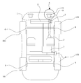
도 1은 본 발명에 의한 자동차의 구성을 보인 평면도.
도 2는 본 발명에 의한 동력전달 계통의 계략적인 구성도
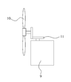
도 3은 본 발명의 풍력 발전기의 계략적인 구성을 보인 구성도
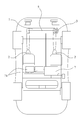
도 4는 본 발명에 의한 동력전달 계통의 다른 실시예를 보인 구성도1 is a plan view showing the configuration of a vehicle according to the present invention.
2 is a schematic configuration diagram of a power transmission system according to the present invention;
Figure 3 is a schematic view showing a schematic configuration of the wind generator of the present invention
Figure 4 is a block diagram showing another embodiment of the power transmission system according to the present invention
이하, 본 발명에 의한 발전장치에 의해 생산된 전기를 동력으로 사용하는 자동차에 관한 구체적인 실시예를 도면과 관련하여 상세하게 살펴보면 다음과 같다.Hereinafter, a detailed embodiment of a vehicle using electricity generated by a power generation apparatus according to the present invention as a power will be described in detail with reference to the accompanying drawings.
도 1은 본 발명에 의한 자동차의 구성을 보인 평면도이며, 도 2는 본 발명에 의한 동력전달 계통의 계략적인 시스템 구성도, 도 3은 본 발명의 풍력 발전기의 계략적인 구성을 보인 구성도, 도 4는 본 발명에 의한 동력전달 계통의 다른 실시예를 보인 구성도이다.1 is a plan view showing the configuration of a vehicle according to the present invention, Figure 2 is a schematic system configuration diagram of a power transmission system according to the present invention, Figure 3 is a configuration diagram showing a schematic configuration of a wind generator of the present invention, Figure 4 is a configuration diagram showing another embodiment of the power transmission system according to the present invention.
도 1에서 도시한 바와 같이 자동차에 있어서 발명에 따른 발전장치는 기존의 엔진룸(100)에 설치되도록 하는 것이 바람직하지만, 자동차의 생산기술발전에 따라 그 설치위치는 다양하게 변경될 수 있다.As shown in FIG. 1, the power generation apparatus according to the invention in the vehicle is preferably installed in the existing
도 1 내지 3에 도시한 바와 같이, 발전장치는 자동차의 엔진룸(100)에 발전기(1)를 설치하고 발전되는 전기를 충전할 수 있도록 축전지(7)와 전기적으로 연결하는 한편, 발전을 위한 회전력을 얻을 수 있게 발전기(1)의 회전축(5)을 자동차의 휠(101)과 별도로 구비되는 자동차 하부 바퀴(2)에 연결하며, 상기 자동차의 차체 윗부분에 태양전지모듈(4)을 설치하여 축전지(7)와 전기적으로 연결되게 함으로써 태양광에 의한 전기도 축전지에 충전할 수 있게 구성된다.As shown in Figures 1 to 3, the generator is installed in the
상기 발전기(1)는 터빈 발전기, 수차 발전기, 무브러시 교류발전기, 고주파 발전기, 복권 발전기 또는 반도체 발전기와 같은 다양한 직류 발전기 또는 교류 발전기로 구현가능하다.The generator 1 may be implemented as various DC generators or alternators such as turbine generators, aberration generators, brushless alternators, high frequency generators, lottery generators or semiconductor generators.
또한, 라지에이터 그릴과 인접하는 상기 엔진룸 내측에는 회전팬(10)과 풍력 발전기(9)가 연결되어 있으며, 상기 라지에이터 그릴과 별도로 공기유입구(미도시)가 상기 회전팬(10)의 전방에 형성되어 있어 상기 공기유입구(미도시)로 자동차 주행중 유입되는 바람에 의해 상기 회전팬(10)이 회전구동함에 따라 상기 풍력 발전기(9)에서 생산되는 전력이 상기 축전지(7)로 충전되도록 구성된다.In addition, a
즉, 상기 발전기(1)와 태양전지모듈(4), 풍력 발전기(9)는 각각이 상기 축전지(7)와 전기적으로 연결되어 있어 생산되는 전력 모두가 상기 축전지(7)로 집중되어 충전이 이루어지게 되며, 상기 축전지(7)는 상기 자동차의 각 휠(101)에 구비되는 모터(6)와 연결되어 충전된 전력을 공급하게 된다.That is, the generator 1, the
여기서, 상기 모터(6)는 속도제어장치(8)와 전기적으로 연결되어 상기 축전지(7)에서 공급되는 전력을 할당받아 원하는 속도로 가감속이 이루어지게 된다.In this case, the
이상과 같이 구성된 본 발명의 실시예를 통한 작용을 구체적으로 설명하면 다음과 같다.Referring to the operation through the embodiment of the present invention configured as described above in detail.
먼저, 일반적인 자동차와 같이 시동키를 이용하여 시동을 걸게 되면, 최초에 축전지(7)에 충전되어 있는 전기가 각 휠(101)에 구비되는 모터(6)로 공급됨에 따라 상기 모터(6)를 구동시켜주게 되므로 자동차가 주행하게 된다.First, when starting by using a start key as in a typical car, the electric power initially charged in the storage battery (7) is supplied to the motor (6) provided in each
그러면 자동차가 출발을 하여 시속 60km ~ 90km로 주행할 때 운전자가 충전이 필요하다고 판단되어 충전키를 누르면 자동변속기(3)가 자동으로 움직여 하부 바퀴(2)를 지면에 닿게 하고 상기 바퀴(2)에 의해 발전기(1)의 회전축이 분당 3,000 ~ 5,000번 회전하여 발전이 이루어지게 되어 충분한 전기를 축전지(7)에 충전할 수 있다. 본 발명은 이에 한정되지 않으며, 바퀴(2)를 자동차가 출발할 때부터 지면에 닿도록 하고, 자동변속기(3)의 기어비를 조절함으로써, 회전축의 분당 회전수가 3,000번 미만일 경우에도 축전지(7)에 전기를 충전할 수 있다. Then, when the driver starts and runs at 60km ~ 90km / h, the driver determines that charging is required. When the driver presses the charging key, the automatic transmission (3) automatically moves to bring the lower wheel (2) to the ground and the wheel (2) By the rotary shaft of the generator 1 is rotated 3,000 ~ 5,000 times per minute to generate power can be charged sufficient electricity to the storage battery (7). The present invention is not limited thereto, and the
또한, 회전축의 분당 회전수가 5,000번을 초과할 경우, 자동변속기(3)의 기어비를 조절하여, 보조 축전지(71)에 전기를 충전할 수 있다. 또한, 보조 축전지(71) 또는 축전지(7)의 과충전 전력을 강제적으로 방전시키는 보호회로를 통해 축전기(7)의 과부하 상태로 인한 내부 열 발생 및 기기 손상을 예방할 수 있다. In addition, when the number of revolutions per minute of the rotary shaft exceeds 5,000, the gear ratio of the
그리고, 상기 발전기(1)와 별도로 구비되는 풍력 발전기(9)는 회전팬(10)과 직각으로 기어(101)에 의해 연결되어 있으며, 전방에 형성된 공기유입구(미도시)로 유입되는 바람에 의해 상기 회전팬(10)이 회전하게 되면, 상기 회전팬(10)의 회전이 상기 기어(101)를 통해 상기 풍력 발전기(9)로 전달되어 여기서 생산되는 전력을 상기 축전지(7)로 충전할 수 있으며, 운전자의 의도와 상관없이 자동차가 주행하는 동시에 전력을 생산할 수도 있으나, 별도로 구비되는 공기유입구 차단수단(미도시)에 의해 운전자의 의도에 따라 풍력 발전기(9)의 전력생산을 조절할 수도 있다.In addition, the
또한, 자동차의 윗부분에는 태양광 조사에 의해 기전력을 생산하는 반도체 광기전력 효과를 이용하는 태양전지모듈(4)을 설치하여 태양광에 의한 발전을 통해 상기 축전지에 전력을 충전하게 되며, 자동차 차체의 크기 및 디자인에 따라 1개의 태양전지모듈 또는 태양전지모듈 어레이를 구성할 수 있다.In addition, the
도 4는 본 발명에 의한 동력전달 계통의 다른 실시예를 보인 구성도로서, 상기 발전기(1)에는 상기 바퀴(2)가 둘 이상이 구비될 수 있으며, 상기 발전기(1) 또한 둘 이상이 구비될 수 있다.Figure 4 is a block diagram showing another embodiment of the power transmission system according to the present invention, the generator 1 may be provided with two or
상기와 같이 자동차가 주행할 때 얻어지는 자동차 하부 바퀴(2)에 의해서 발전기(1)가 생산한 전기와, 풍력 발전기(9)가 생산한 전기, 태양전지모듈(4)에 의해서 얻어지는 전기를 사용하여 자동차를 주행시키게 된다.By using the electricity produced by the generator 1, the electricity produced by the
한편, 상기 축전지(7)에는 보호회로(미도시)가 구성되는데 주행 또는 정차된 동안에 충전되는 전력이 상기 축전지(7)의 용량을 초과하는 과충전이 발생하면 상기 축전지(7)에 구성되어 있는 상기 보호회로(미도시)가 작동되어 현재 충전용량과 공급되는 전력을 계산한 후 과충전되는 전력을 회로적 저항으로 강제방전시켜 과충전에 의한 상기 축전지(7)의 손상 및 상기 각 휠(101)의 모터(6)와 자동차의 기타 전기장치가 전기 회로적으로 손상되는 것이 방지되게 한다.On the other hand, the
더불어, 축전지(7)로 공급되는 전력량이 상기 축전지의 충전용량 이상으로 공급되면, 보조 축전지(71)로 여분의 전력량을 별도로 충전할 수 있으며, 상기 보조 축전지(71)는 하나 또는 둘 이상의 다수로 구성될 수 있고, 그에 따라 과충전에 따른 전기회로의 손상 없이 여분의 전력을 추가로 저장할 수 있게 된다.In addition, when the amount of power supplied to the
그리고, 자동차의 각종 전력소모부품은 상기 축전지(7)를 이용하여 일반 자동차의 배터리의 전기를 사용하듯이 사용하면 되는 것이며, 자동차가 주행중에 소진되는 전기는 발전기(1)와 풍력 발전기(9) 및 태양전지모듈(4)로부터 계속적으로 보충될 수 있기 때문에 기존의 전기 자동차에 있어 축전지의 충전용량 부족으로 인한 단점을 해결할 수 있다.
The various power consumption parts of the automobile may be used as the electricity of the battery of a general vehicle by using the
1: 발전기 7: 축전지
2: 바퀴 71: 보조 축전지
3: 자동 변속기 8: 속도제어장치
4: 태양전지모듈 9: 풍력 발전기
5: 회전축 10: 회전팬
6: 모터 101: 기어1: generator 7: storage battery
2: wheel 71: auxiliary battery
3: automatic transmission 8: speed control
4: solar module 9: wind generator
5: rotating shaft 10: rotating fan
6: motor 101: gear
Claims (10)
상기 발전기의 회전조절 및 과부하를 방지하는 자동변속기와;
상기 발전기에 연결되어 회전을 발생시키는 바퀴 및;
상기 자동차의 윗부분에 태양에너지를 흡수하여 전기에너지로 변환시키는 태양에너지변환 수단과;
상기 자동차의 주행 중 발전기 충전키를 누르면, 상기 자동변속기가 상기 바퀴를 지면에 닿도록 구동시켜 상기 바퀴의 회전에 의해 상기 발전기가 회전함으로써 축전지에 전력을 공급하는 것을 특징으로 하는 발전장치에 의해 생산된 전기를 동력으로 사용하는 자동차.
A generator installed in the engine room of the vehicle;
An automatic transmission preventing rotation control and overload of the generator;
A wheel connected to the generator to generate rotation;
Solar energy conversion means for absorbing solar energy in an upper portion of the vehicle and converting the solar energy into electrical energy;
When the generator charging key is pressed while driving the vehicle, the automatic transmission drives the wheels to the ground, and the generator rotates by the rotation of the wheels, thereby producing power by the generator. Using powered electricity as a power source.
상기 태양에너지변환 수단은,
태양전지모듈로 구성되는 것을 특징으로 하는 발전장치에 의해 생산된 전기를 동력으로 사용하는 자동차.
The method of claim 1,
The solar energy conversion means,
A vehicle using electricity produced by a power generation device, characterized in that consisting of a solar cell module as power.
주행으로 인해 상기 엔진룸 내부로 공급되는 유입공기를 이용하여 전기에너지를 생산하는 풍력에너지 변환 수단을 더 포함하여 구성되는 것을 특징으로 하는 발전장치에 의해 생산된 전기를 동력으로 사용하는 자동차.
The method of claim 1,
A vehicle using electricity produced by a power generation device, characterized in that it further comprises a wind energy conversion means for producing electrical energy by using the inlet air supplied into the engine room due to running.
상기 풍력에너지변환 수단은,
회전팬과 연결되는 풍력 발전기가 상기 축전지와 전기적으로 연결되는 것을 특징으로 하는 발전장치에 의해 생산된 전기를 동력으로 사용하는 자동차.
The method of claim 3, wherein
The wind energy conversion means,
A wind power generator connected to a rotating fan is electrically connected to the storage battery.
상기 자동차의 60km ~ 90km 주행중 상기 발전기 충전키를 누르면 상기 자동변속기의 구동으로 상기 바퀴가 지면에 닿도록 하강하여 분당 3,000 ~ 5,000번의 회전으로 충전되는 것을 특징으로 하는 발전장치에 의해 생산된 전기를 동력으로 사용하는 자동차.
The method according to any one of claims 2 to 4,
When the generator charging key is pressed while driving the vehicle 60 km to 90 km, the wheel is lowered to reach the ground by the drive of the automatic transmission, and the electric power produced by the generator is charged at 3,000 to 5,000 revolutions per minute. Used as a car.
상기 축전지는
상기 발전기 및 풍력 발전기에서 생산되는 전력이 충전용량을 넘어설 경우 과충전 전력을 강제적으로 방전시키는 보호회로를 더 포함하여 구성되는 것을 특징으로 하는 발전장치에 의해 생산된 전기를 동력으로 사용하는 자동차.
The method of claim 5
The storage battery
When the power produced by the generator and the wind generator exceeds the charging capacity, the vehicle using the electricity produced by the power generating device further comprises a protection circuit for forcibly discharging the overcharge power.
상기 축전지는
상기 발전기 및 풍력 발전기에서 생산되는 전력이 충전용량을 넘어설 경우 과충전 전력을 충전하는 보조 축전지를 더 포함하여 구성되는 것을 특징으로 하는 발전장치에 의해 생산된 전기를 동력으로 사용하는 자동차.
The method of claim 5
The storage battery
When the power produced by the generator and the wind generator exceeds the charging capacity, the vehicle using the electricity produced by the power generation device characterized in that it further comprises an auxiliary storage battery for charging overcharge power.
상기 보조 축전지는 적어도 하나 이상으로 구성되는 것을 특징으로 하는 발전장치에 의해 생산된 전기를 동력으로 사용하는 자동차.
The method of claim 7, wherein
The auxiliary storage battery is a vehicle using the electricity produced by the power generation device, characterized in that composed of at least one.
상기 발전기는 적어도 하나 이상으로 구비되는 것을 특징으로 하는 발전장치에 의해 생산된 전기를 동력으로 사용하는 자동차.
The method according to any one of claims 6 to 8
The generator uses at least one of the electricity produced by the power generation device, characterized in that provided with at least one vehicle.
상기 바퀴는 상기 발전기에 적어도 하나 이상으로 구비되는 것을 특징으로 하는 발전장치에 의해 생산된 전기를 동력으로 사용하는 자동차.
The method of claim 9
The wheel is a vehicle using the electricity produced by the power generation device, characterized in that provided with at least one generator in the generator.
Applications Claiming Priority (2)
| Application Number | Priority Date | Filing Date | Title |
|---|---|---|---|
| KR1020100062397 | 2010-06-28 | ||
| KR20100062397 | 2010-06-28 |
Publications (2)
| Publication Number | Publication Date |
|---|---|
| KR20120001633A true KR20120001633A (en) | 2012-01-04 |
| KR101301827B1 KR101301827B1 (en) | 2013-08-29 |
Family
ID=45609280
Family Applications (1)
| Application Number | Title | Priority Date | Filing Date |
|---|---|---|---|
| KR1020110062045A Expired - Fee Related KR101301827B1 (en) | 2010-06-28 | 2011-06-27 | Motor Vehicle Using Electric Power by Power Plant |
Country Status (1)
| Country | Link |
|---|---|
| KR (1) | KR101301827B1 (en) |
Cited By (6)
| Publication number | Priority date | Publication date | Assignee | Title |
|---|---|---|---|---|
| CN104002689A (en) * | 2014-06-09 | 2014-08-27 | 赵尚庭 | Wind-solar complementary electric vehicle power system and control method thereof |
| KR20160080607A (en) * | 2014-12-30 | 2016-07-08 | 한국기술교육대학교 산학협력단 | HYBRID CAR HAVING Li-Po BATTERY |
| WO2017018747A1 (en) * | 2015-07-30 | 2017-02-02 | 주식회사 한글과컴퓨터 | Method for providing guidance on accessories for autonomous smart car and server for same |
| CN112874341A (en) * | 2021-02-24 | 2021-06-01 | 广西科技大学 | Solar mobile charging device |
| WO2023234810A1 (en) * | 2022-05-31 | 2023-12-07 | Almalki Ibtisam | Equivalent system for generating electricity for an electric or hybrid vehicle |
| WO2025211489A1 (en) * | 2024-04-04 | 2025-10-09 | 김용호 | Electric vehicle capable of charging using wind power energy |
Families Citing this family (2)
| Publication number | Priority date | Publication date | Assignee | Title |
|---|---|---|---|---|
| KR102085863B1 (en) | 2018-06-11 | 2020-03-06 | 장경한 | Generating apparatus using a magnetic substance and a wind power |
| KR102772352B1 (en) | 2024-12-20 | 2025-02-21 | 김용호 | Wind-power continuously chargable electric vehicle |
Family Cites Families (4)
| Publication number | Priority date | Publication date | Assignee | Title |
|---|---|---|---|---|
| KR20000010126A (en) * | 1998-07-30 | 2000-02-15 | 민병길 | Auxiliary Charging Device for Electric Vehicles |
| JP2001352608A (en) * | 2000-06-02 | 2001-12-21 | Keiyo Ito | Charging system for electric vehicle |
| KR20090098028A (en) * | 2008-03-13 | 2009-09-17 | 김상봉 | Automobiles using electricity produced by the power generator as power |
| KR20090077745A (en) * | 2009-06-26 | 2009-07-15 | 김용성 | Electric power production apparatus using the electric power of the electric vehicle and a battery charging method using the same |
-
2011
- 2011-06-27 KR KR1020110062045A patent/KR101301827B1/en not_active Expired - Fee Related
Cited By (6)
| Publication number | Priority date | Publication date | Assignee | Title |
|---|---|---|---|---|
| CN104002689A (en) * | 2014-06-09 | 2014-08-27 | 赵尚庭 | Wind-solar complementary electric vehicle power system and control method thereof |
| KR20160080607A (en) * | 2014-12-30 | 2016-07-08 | 한국기술교육대학교 산학협력단 | HYBRID CAR HAVING Li-Po BATTERY |
| WO2017018747A1 (en) * | 2015-07-30 | 2017-02-02 | 주식회사 한글과컴퓨터 | Method for providing guidance on accessories for autonomous smart car and server for same |
| CN112874341A (en) * | 2021-02-24 | 2021-06-01 | 广西科技大学 | Solar mobile charging device |
| WO2023234810A1 (en) * | 2022-05-31 | 2023-12-07 | Almalki Ibtisam | Equivalent system for generating electricity for an electric or hybrid vehicle |
| WO2025211489A1 (en) * | 2024-04-04 | 2025-10-09 | 김용호 | Electric vehicle capable of charging using wind power energy |
Also Published As
| Publication number | Publication date |
|---|---|
| KR101301827B1 (en) | 2013-08-29 |
Similar Documents
| Publication | Publication Date | Title |
|---|---|---|
| KR101301827B1 (en) | Motor Vehicle Using Electric Power by Power Plant | |
| Mohammadi | Design, analysis, and electrification of a solar-powered electric vehicle | |
| US20060250902A1 (en) | Plug-in hybrid vehicle with fast energy storage | |
| CN101610932A (en) | Electric vehicle, vehicle charging device and vehicle charging system | |
| CN202294329U (en) | Electric vehicle with electricity generated by wind energy, solar energy and fuels | |
| KR20140141784A (en) | Electric vehicle for charging the electricity by using wind power | |
| CN201457104U (en) | Hybrid Electric Vehicle | |
| CN204452072U (en) | A kind of electronlmobil of self power generation | |
| KR20190063743A (en) | Electric vehicle with dual battery using solar and battery charging method thereof | |
| CN102501778A (en) | Extended-range electric vehicle energy distribution method based on dual-voltage composite energy storage system | |
| CN101670777A (en) | Solar hybrid vehicle | |
| CN103465792A (en) | Wind/light energy electric automobile | |
| CN203902312U (en) | Wind-solar complementary self-charging electric vehicle | |
| KR200268814Y1 (en) | Electric Power Supply Unit in Electricity Vehicles | |
| CN2538600Y (en) | Multifunctional electric generating system for automobile | |
| JP2014042403A (en) | Charging device, solar system, electrical system, and vehicle | |
| CN103042933A (en) | Wind energy, solar energy and fuel power hybrid power generation electric vehicle | |
| CN204526857U (en) | A kind of thousand kilometers of course continuation mileage electronlmobils | |
| CN101364756A (en) | Vehicle wheel electricity generator | |
| CN111497629A (en) | Electric automobile and power supply control method | |
| CN223877877U (en) | Composite energy automobile | |
| KR20230004385A (en) | Power generation system for electric vehicle | |
| CN205292328U (en) | Electricity caterpillar drive formula vehicle | |
| Kumar et al. | Assessment of Performance and Characteristics of a Hybrid Charging Scheme for Electric Vehicle Battery | |
| CN204323096U (en) | A kind of power system of electric automobile and electronlmobil |
Legal Events
| Date | Code | Title | Description |
|---|---|---|---|
| A201 | Request for examination | ||
| PA0109 | Patent application |
St.27 status event code: A-0-1-A10-A12-nap-PA0109 |
|
| PA0201 | Request for examination |
St.27 status event code: A-1-2-D10-D11-exm-PA0201 |
|
| A302 | Request for accelerated examination | ||
| PA0302 | Request for accelerated examination |
St.27 status event code: A-1-2-D10-D17-exm-PA0302 St.27 status event code: A-1-2-D10-D16-exm-PA0302 |
|
| PG1501 | Laying open of application |
St.27 status event code: A-1-1-Q10-Q12-nap-PG1501 |
|
| E902 | Notification of reason for refusal | ||
| PE0902 | Notice of grounds for rejection |
St.27 status event code: A-1-2-D10-D21-exm-PE0902 |
|
| E13-X000 | Pre-grant limitation requested |
St.27 status event code: A-2-3-E10-E13-lim-X000 |
|
| P11-X000 | Amendment of application requested |
St.27 status event code: A-2-2-P10-P11-nap-X000 |
|
| P13-X000 | Application amended |
St.27 status event code: A-2-2-P10-P13-nap-X000 |
|
| E90F | Notification of reason for final refusal | ||
| PE0902 | Notice of grounds for rejection |
St.27 status event code: A-1-2-D10-D21-exm-PE0902 |
|
| P11-X000 | Amendment of application requested |
St.27 status event code: A-2-2-P10-P11-nap-X000 |
|
| P13-X000 | Application amended |
St.27 status event code: A-2-2-P10-P13-nap-X000 |
|
| E701 | Decision to grant or registration of patent right | ||
| PE0701 | Decision of registration |
St.27 status event code: A-1-2-D10-D22-exm-PE0701 |
|
| GRNT | Written decision to grant | ||
| PR0701 | Registration of establishment |
St.27 status event code: A-2-4-F10-F11-exm-PR0701 |
|
| PR1002 | Payment of registration fee |
St.27 status event code: A-2-2-U10-U11-oth-PR1002 Fee payment year number: 1 |
|
| PG1601 | Publication of registration |
St.27 status event code: A-4-4-Q10-Q13-nap-PG1601 |
|
| FPAY | Annual fee payment |
Payment date: 20160629 Year of fee payment: 4 |
|
| PR1001 | Payment of annual fee |
St.27 status event code: A-4-4-U10-U11-oth-PR1001 Fee payment year number: 4 |
|
| FPAY | Annual fee payment |
Payment date: 20170920 Year of fee payment: 5 |
|
| PR1001 | Payment of annual fee |
St.27 status event code: A-4-4-U10-U11-oth-PR1001 Fee payment year number: 5 |
|
| FPAY | Annual fee payment |
Payment date: 20180725 Year of fee payment: 6 |
|
| PR1001 | Payment of annual fee |
St.27 status event code: A-4-4-U10-U11-oth-PR1001 Fee payment year number: 6 |
|
| P22-X000 | Classification modified |
St.27 status event code: A-4-4-P10-P22-nap-X000 |
|
| FPAY | Annual fee payment |
Payment date: 20190610 Year of fee payment: 7 |
|
| PR1001 | Payment of annual fee |
St.27 status event code: A-4-4-U10-U11-oth-PR1001 Fee payment year number: 7 |
|
| PR1001 | Payment of annual fee |
St.27 status event code: A-4-4-U10-U11-oth-PR1001 Fee payment year number: 8 |
|
| PR1001 | Payment of annual fee |
St.27 status event code: A-4-4-U10-U11-oth-PR1001 Fee payment year number: 9 |
|
| P22-X000 | Classification modified |
St.27 status event code: A-4-4-P10-P22-nap-X000 |
|
| PR1001 | Payment of annual fee |
St.27 status event code: A-4-4-U10-U11-oth-PR1001 Fee payment year number: 10 |
|
| PR1001 | Payment of annual fee |
St.27 status event code: A-4-4-U10-U11-oth-PR1001 Fee payment year number: 11 |
|
| P22-X000 | Classification modified |
St.27 status event code: A-4-4-P10-P22-nap-X000 |
|
| PC1903 | Unpaid annual fee |
St.27 status event code: A-4-4-U10-U13-oth-PC1903 Not in force date: 20240824 Payment event data comment text: Termination Category : DEFAULT_OF_REGISTRATION_FEE |
|
| PC1903 | Unpaid annual fee |
St.27 status event code: N-4-6-H10-H13-oth-PC1903 Ip right cessation event data comment text: Termination Category : DEFAULT_OF_REGISTRATION_FEE Not in force date: 20240824 |