KR20110111364A - Air pollution control filter elements for filtration system - Google Patents
Air pollution control filter elements for filtration system Download PDFInfo
- Publication number
- KR20110111364A KR20110111364A KR1020117011595A KR20117011595A KR20110111364A KR 20110111364 A KR20110111364 A KR 20110111364A KR 1020117011595 A KR1020117011595 A KR 1020117011595A KR 20117011595 A KR20117011595 A KR 20117011595A KR 20110111364 A KR20110111364 A KR 20110111364A
- Authority
- KR
- South Korea
- Prior art keywords
- sleeve
- fluid stream
- particulate filter
- filter bag
- downstream
- Prior art date
Links
Images

Classifications
-
- B—PERFORMING OPERATIONS; TRANSPORTING
- B01—PHYSICAL OR CHEMICAL PROCESSES OR APPARATUS IN GENERAL
- B01D—SEPARATION
- B01D46/00—Filters or filtering processes specially modified for separating dispersed particles from gases or vapours
- B01D46/02—Particle separators, e.g. dust precipitators, having hollow filters made of flexible material
-
- B—PERFORMING OPERATIONS; TRANSPORTING
- B01—PHYSICAL OR CHEMICAL PROCESSES OR APPARATUS IN GENERAL
- B01D—SEPARATION
- B01D39/00—Filtering material for liquid or gaseous fluids
- B01D39/14—Other self-supporting filtering material ; Other filtering material
- B01D39/16—Other self-supporting filtering material ; Other filtering material of organic material, e.g. synthetic fibres
- B01D39/1692—Other shaped material, e.g. perforated or porous sheets
-
- B—PERFORMING OPERATIONS; TRANSPORTING
- B01—PHYSICAL OR CHEMICAL PROCESSES OR APPARATUS IN GENERAL
- B01D—SEPARATION
- B01D39/00—Filtering material for liquid or gaseous fluids
- B01D39/08—Filter cloth, i.e. woven, knitted or interlaced material
-
- B—PERFORMING OPERATIONS; TRANSPORTING
- B01—PHYSICAL OR CHEMICAL PROCESSES OR APPARATUS IN GENERAL
- B01D—SEPARATION
- B01D39/00—Filtering material for liquid or gaseous fluids
- B01D39/08—Filter cloth, i.e. woven, knitted or interlaced material
- B01D39/083—Filter cloth, i.e. woven, knitted or interlaced material of organic material
-
- B—PERFORMING OPERATIONS; TRANSPORTING
- B01—PHYSICAL OR CHEMICAL PROCESSES OR APPARATUS IN GENERAL
- B01D—SEPARATION
- B01D39/00—Filtering material for liquid or gaseous fluids
- B01D39/14—Other self-supporting filtering material ; Other filtering material
- B01D39/16—Other self-supporting filtering material ; Other filtering material of organic material, e.g. synthetic fibres
- B01D39/1607—Other self-supporting filtering material ; Other filtering material of organic material, e.g. synthetic fibres the material being fibrous
- B01D39/1623—Other self-supporting filtering material ; Other filtering material of organic material, e.g. synthetic fibres the material being fibrous of synthetic origin
-
- B—PERFORMING OPERATIONS; TRANSPORTING
- B01—PHYSICAL OR CHEMICAL PROCESSES OR APPARATUS IN GENERAL
- B01D—SEPARATION
- B01D39/00—Filtering material for liquid or gaseous fluids
- B01D39/14—Other self-supporting filtering material ; Other filtering material
- B01D39/20—Other self-supporting filtering material ; Other filtering material of inorganic material, e.g. asbestos paper, metallic filtering material of non-woven wires
- B01D39/2055—Carbonaceous material
- B01D39/2058—Carbonaceous material the material being particulate
-
- B—PERFORMING OPERATIONS; TRANSPORTING
- B01—PHYSICAL OR CHEMICAL PROCESSES OR APPARATUS IN GENERAL
- B01D—SEPARATION
- B01D39/00—Filtering material for liquid or gaseous fluids
- B01D39/14—Other self-supporting filtering material ; Other filtering material
- B01D39/20—Other self-supporting filtering material ; Other filtering material of inorganic material, e.g. asbestos paper, metallic filtering material of non-woven wires
- B01D39/2055—Carbonaceous material
- B01D39/2065—Carbonaceous material the material being fibrous
-
- B—PERFORMING OPERATIONS; TRANSPORTING
- B01—PHYSICAL OR CHEMICAL PROCESSES OR APPARATUS IN GENERAL
- B01D—SEPARATION
- B01D46/00—Filters or filtering processes specially modified for separating dispersed particles from gases or vapours
- B01D46/0002—Casings; Housings; Frame constructions
- B01D46/0004—Details of removable closures, lids, caps or filter heads
-
- B—PERFORMING OPERATIONS; TRANSPORTING
- B01—PHYSICAL OR CHEMICAL PROCESSES OR APPARATUS IN GENERAL
- B01D—SEPARATION
- B01D46/00—Filters or filtering processes specially modified for separating dispersed particles from gases or vapours
- B01D46/0002—Casings; Housings; Frame constructions
- B01D46/0005—Mounting of filtering elements within casings, housings or frames
-
- B—PERFORMING OPERATIONS; TRANSPORTING
- B01—PHYSICAL OR CHEMICAL PROCESSES OR APPARATUS IN GENERAL
- B01D—SEPARATION
- B01D46/00—Filters or filtering processes specially modified for separating dispersed particles from gases or vapours
- B01D46/0027—Filters or filtering processes specially modified for separating dispersed particles from gases or vapours with additional separating or treating functions
- B01D46/0036—Filters or filtering processes specially modified for separating dispersed particles from gases or vapours with additional separating or treating functions by adsorption or absorption
-
- B—PERFORMING OPERATIONS; TRANSPORTING
- B01—PHYSICAL OR CHEMICAL PROCESSES OR APPARATUS IN GENERAL
- B01D—SEPARATION
- B01D46/00—Filters or filtering processes specially modified for separating dispersed particles from gases or vapours
- B01D46/02—Particle separators, e.g. dust precipitators, having hollow filters made of flexible material
- B01D46/04—Cleaning filters
-
- B—PERFORMING OPERATIONS; TRANSPORTING
- B01—PHYSICAL OR CHEMICAL PROCESSES OR APPARATUS IN GENERAL
- B01D—SEPARATION
- B01D46/00—Filters or filtering processes specially modified for separating dispersed particles from gases or vapours
- B01D46/02—Particle separators, e.g. dust precipitators, having hollow filters made of flexible material
- B01D46/06—Particle separators, e.g. dust precipitators, having hollow filters made of flexible material with means keeping the working surfaces flat
-
- B—PERFORMING OPERATIONS; TRANSPORTING
- B01—PHYSICAL OR CHEMICAL PROCESSES OR APPARATUS IN GENERAL
- B01D—SEPARATION
- B01D46/00—Filters or filtering processes specially modified for separating dispersed particles from gases or vapours
- B01D46/56—Filters or filtering processes specially modified for separating dispersed particles from gases or vapours with multiple filtering elements, characterised by their mutual disposition
- B01D46/58—Filters or filtering processes specially modified for separating dispersed particles from gases or vapours with multiple filtering elements, characterised by their mutual disposition connected in parallel
-
- B—PERFORMING OPERATIONS; TRANSPORTING
- B01—PHYSICAL OR CHEMICAL PROCESSES OR APPARATUS IN GENERAL
- B01D—SEPARATION
- B01D46/00—Filters or filtering processes specially modified for separating dispersed particles from gases or vapours
- B01D46/56—Filters or filtering processes specially modified for separating dispersed particles from gases or vapours with multiple filtering elements, characterised by their mutual disposition
- B01D46/62—Filters or filtering processes specially modified for separating dispersed particles from gases or vapours with multiple filtering elements, characterised by their mutual disposition connected in series
-
- B—PERFORMING OPERATIONS; TRANSPORTING
- B01—PHYSICAL OR CHEMICAL PROCESSES OR APPARATUS IN GENERAL
- B01D—SEPARATION
- B01D46/00—Filters or filtering processes specially modified for separating dispersed particles from gases or vapours
- B01D46/66—Regeneration of the filtering material or filter elements inside the filter
- B01D46/70—Regeneration of the filtering material or filter elements inside the filter by acting counter-currently on the filtering surface, e.g. by flushing on the non-cake side of the filter
- B01D46/71—Regeneration of the filtering material or filter elements inside the filter by acting counter-currently on the filtering surface, e.g. by flushing on the non-cake side of the filter with pressurised gas, e.g. pulsed air
-
- B—PERFORMING OPERATIONS; TRANSPORTING
- B01—PHYSICAL OR CHEMICAL PROCESSES OR APPARATUS IN GENERAL
- B01D—SEPARATION
- B01D46/00—Filters or filtering processes specially modified for separating dispersed particles from gases or vapours
- B01D46/88—Replacing filter elements
-
- B—PERFORMING OPERATIONS; TRANSPORTING
- B01—PHYSICAL OR CHEMICAL PROCESSES OR APPARATUS IN GENERAL
- B01D—SEPARATION
- B01D50/00—Combinations of methods or devices for separating particles from gases or vapours
- B01D50/20—Combinations of devices covered by groups B01D45/00 and B01D46/00
-
- B—PERFORMING OPERATIONS; TRANSPORTING
- B01—PHYSICAL OR CHEMICAL PROCESSES OR APPARATUS IN GENERAL
- B01D—SEPARATION
- B01D53/00—Separation of gases or vapours; Recovering vapours of volatile solvents from gases; Chemical or biological purification of waste gases, e.g. engine exhaust gases, smoke, fumes, flue gases, aerosols
- B01D53/34—Chemical or biological purification of waste gases
- B01D53/46—Removing components of defined structure
- B01D53/64—Heavy metals or compounds thereof, e.g. mercury
-
- B—PERFORMING OPERATIONS; TRANSPORTING
- B01—PHYSICAL OR CHEMICAL PROCESSES OR APPARATUS IN GENERAL
- B01D—SEPARATION
- B01D2239/00—Aspects relating to filtering material for liquid or gaseous fluids
- B01D2239/04—Additives and treatments of the filtering material
- B01D2239/0407—Additives and treatments of the filtering material comprising particulate additives, e.g. adsorbents
-
- B—PERFORMING OPERATIONS; TRANSPORTING
- B01—PHYSICAL OR CHEMICAL PROCESSES OR APPARATUS IN GENERAL
- B01D—SEPARATION
- B01D2239/00—Aspects relating to filtering material for liquid or gaseous fluids
- B01D2239/06—Filter cloth, e.g. knitted, woven non-woven; self-supported material
- B01D2239/065—More than one layer present in the filtering material
- B01D2239/0654—Support layers
-
- B—PERFORMING OPERATIONS; TRANSPORTING
- B01—PHYSICAL OR CHEMICAL PROCESSES OR APPARATUS IN GENERAL
- B01D—SEPARATION
- B01D2239/00—Aspects relating to filtering material for liquid or gaseous fluids
- B01D2239/08—Special characteristics of binders
- B01D2239/086—Binders between particles or fibres
-
- B—PERFORMING OPERATIONS; TRANSPORTING
- B01—PHYSICAL OR CHEMICAL PROCESSES OR APPARATUS IN GENERAL
- B01D—SEPARATION
- B01D2239/00—Aspects relating to filtering material for liquid or gaseous fluids
- B01D2239/12—Special parameters characterising the filtering material
- B01D2239/1258—Permeability
-
- B—PERFORMING OPERATIONS; TRANSPORTING
- B01—PHYSICAL OR CHEMICAL PROCESSES OR APPARATUS IN GENERAL
- B01D—SEPARATION
- B01D2253/00—Adsorbents used in seperation treatment of gases and vapours
- B01D2253/10—Inorganic adsorbents
- B01D2253/102—Carbon
-
- B—PERFORMING OPERATIONS; TRANSPORTING
- B01—PHYSICAL OR CHEMICAL PROCESSES OR APPARATUS IN GENERAL
- B01D—SEPARATION
- B01D2257/00—Components to be removed
- B01D2257/60—Heavy metals or heavy metal compounds
- B01D2257/602—Mercury or mercury compounds
-
- B—PERFORMING OPERATIONS; TRANSPORTING
- B01—PHYSICAL OR CHEMICAL PROCESSES OR APPARATUS IN GENERAL
- B01D—SEPARATION
- B01D2258/00—Sources of waste gases
- B01D2258/02—Other waste gases
- B01D2258/0283—Flue gases
Abstract
프로세스 가스 스트림에 의해 발생된 연도 가스와 같은 오염 물질 함유 유체 스트림 내의 수은 및 다른 오염 물질을 포획하기 위한 개량된 여과 장치, 필터링 방법 및 필터링 재료가 개시된다. 개량된 여과 시스템은 2개의 오염 물질 정화층, 즉 미립자를 필터링할 수 있는 상류측 층과, 수은, 다이옥신, 퓨란 및 NOx와 같은 오염 물질을 흡착하고/흡착하거나 촉매화할 수 있는 하류측 층을 포함할 수 있다. 개량된 여과 시스템은 미립자 필터백의 형태일 수 있다. 미립자 필터백은 상류측 층이 백의 내부 체적을 향한 상태로 역방향 공기 여과 시스템에서 사용하기 위해 구성될 수도 있다. 상류측 층은 상류측 층의 상류측에 라미네이팅되어 있는 ePTFE 층을 포함할 수 있다.Improved filtration devices, filtering methods, and filtering materials are disclosed for trapping mercury and other contaminants in contaminant-containing fluid streams, such as flue gases generated by process gas streams. The improved filtration system includes two contaminant purification layers, an upstream layer that can filter particulates and a downstream layer that can adsorb and / or catalyze contaminants such as mercury, dioxins, furans and NO x . It may include. The improved filtration system may be in the form of particulate filter bags. The particulate filter bag may be configured for use in a reverse air filtration system with the upstream layer facing the inner volume of the bag. The upstream layer may comprise an ePTFE layer laminated upstream of the upstream layer.
Description
본 발명은 여과 시스템용 공기 오염 제어 필터 요소 및 이 필터 요소를 이용한 여과 방법에 관한 것이다.The present invention relates to an air pollution control filter element for a filtration system and a filtration method using the filter element.
다양한 산업 분야는 유체 스트림으로부터 오염 물질의 제거를 요구한다. 오염 물질은 미립자 및/또는 화학 오염 물질의 형태일 수 있다. 유체 스트림은 예를 들어 상류측 연소 프로세스로부터 연도 가스(flue gas)의 형태일 수 있다. 예를 들어, 다이옥신, 퓨란, 수은 및 NOx와 같은 오염 물질은 다수의 연소 연도 가스 내에서 상당한 문제점을 야기한다. 이들 오염 물질이 대기로 새어 나오면, 이들은 잠재적으로 인간 건강 및 환경을 손상시킨다. 다수의 산업 및 장소에서, 이들 오염 물질은 현재 규제되고 있다. 더욱이, 연방정부 및 주정부는 새로운 규제를 정규적으로 도입하고/도입하거나 현존하는 규제를 강화하고 있다.Various industries require the removal of contaminants from fluid streams. The contaminants may be in the form of particulates and / or chemical contaminants. The fluid stream may be in the form of flue gas, for example, from an upstream combustion process. For example, contaminants such as dioxins, furans, mercury and NO x cause significant problems in many combustion flue gases. If these pollutants leak into the atmosphere, they potentially damage human health and the environment. In many industries and places these pollutants are currently regulated. Moreover, federal and state governments regularly introduce new regulations and / or strengthen existing regulations.
필터 시스템은 연소 연도 가스의 스트림과 같은 유체 스트림으로부터 미립자를 제거하기 위해 이용될 수 있다. 이러한 시스템은 필터 시스템이 주기적으로 세척되게 하기 위해 정지 시간(down time)을 요구할 수 있다. 더욱이, 이러한 시스템은 재사용을 제한하거나 배제하는 방식으로 작동할 수 있고, 따라서 이러한 시스템을 유지보수하기 위한 정지 시간을 요구하는 요소를 포함할 수 있다. 더욱이, 이러한 시스템은 작동 및 유지 보수에 있어 고비용일 수 있다.The filter system may be used to remove particulates from a fluid stream, such as a stream of combustion flue gas. Such a system may require a down time for the filter system to be cleaned periodically. Moreover, such a system can operate in a way that restricts or excludes reuse, and thus can include elements that require downtime to maintain such a system. Moreover, such a system can be expensive in operation and maintenance.
상기 내용의 견지에서, 본 명세서에 설명되어 있는 실시예의 목적은 감소된 필터 시스템 정지 시간, 감소된 유지보수의 복잡성 및/또는 감소된 교체 비용으로 오염 물질 함유 유체 스트림으로부터 미립자 및/또는 다른 오염 물질을 필터링할 수 있는 개량된 필터링 방법 및 장치를 제공하는 것을 포함할 수 있다. 추가적으로, 현재 및 잠재적인 미래의 오염 물질 규제의 견지에서, 유체 스트림으로부터 오염 물질을 효과적으로 제거하는 오염 여과 시스템의 개량을 위한 진행중인 요구가 존재한다. 더욱이, 부피가 큰 부산물 또는 폐기물 스트림의 생성 없이 오염 물질 제거를 수행하고자 하는 요구가 존재한다.In view of the above, the purpose of the embodiments described herein is to provide particulate and / or other contaminants from contaminant-containing fluid streams with reduced filter system downtime, reduced maintenance complexity, and / or reduced replacement costs. It may include providing an improved filtering method and apparatus that can filter the. In addition, in light of current and potential future pollutant regulations, there is an ongoing need for retrofitting a pollution filtration system that effectively removes contaminants from a fluid stream. Moreover, there is a need to perform contaminant removal without the creation of bulky by-products or waste streams.
본 발명의 일 양태에서, 전술된 목적 중 하나 이상은 제공된 오염 물질 함유 유체 스트림으로부터의 오염 물질의 제거 방법에 의해 성취될 수 있다. 이 방법은 먼저 상류측 요소를 통해 그리고 이어서 하류측 요소를 통해 오염 물질 함유 유체 스트림을 통과시키는 것을 포함할 수 있다. 이 방법은 유체 스트림으로부터 미립자를 제거하기 위해 상류측 요소를 통해 오염 물질 함유 유체 스트림을 통과시키는 것을 포함한다. 상류측 요소는 미리 결정 가능한 크기의 미립자를 제거하도록 구성될 수 있다. 이 방법은 이후에 유체 스트림으로부터 화학 및/또는 기체 오염 물질을 정화하고/정화하거나 제거하기 위해 하류측 요소를 통해 유체 스트림을 통과시키는 것을 더 포함할 수 있다.In one aspect of the invention, one or more of the aforementioned objects can be achieved by a method of removing contaminants from a provided contaminant containing fluid stream. The method may include passing the pollutant containing fluid stream first through the upstream element and then through the downstream element. The method includes passing a contaminant containing fluid stream through the upstream element to remove particulates from the fluid stream. The upstream element can be configured to remove particulates of a predetermined size. The method may then further comprise passing the fluid stream through the downstream element to purify and / or remove chemical and / or gaseous contaminants from the fluid stream.
다른 양태에서, 전술된 목적 중 하나 이상은 제공된 역방향 공기 여과 시스템에서 오염 물질 함유 유체 스트림을 필터링하는 방법에 의해 성취될 수 있다. 오염 물질 함유 유체 스트림은 예를 들어 산업 프로세스로부터의 연소 연도 가스의 스트림일 수 있다. 이 방법은 역방향 공기 여과 시스템의 공급 입구(예를 들어, 튜브 시트) 내의 개구에 필터 장치의 입구 단부를 상호 연결하는 것을 포함할 수 있다. 필터 장치는 미립자 필터백(filter bag) 및 미립자 필터백 둘레에 제거 가능하게 배치된 슬리브를 포함할 수 있다. 미립자 필터백 둘레에 슬리브를 제거 가능하게 배치하는 것(및/또는 슬리브 내에 미립자 필터백을 제거 가능하게 배치하는 것)은 미립자 필터백 유지보수, 유지보수로부터 독립적인 재사용 또는 교체, 슬리브의 재사용 또는 교체를 용이하게 할 수 있다. 이와 관련하여, 특정 유지 보수 작업 중에, 미립자 필터백은 유지보수되거나 교체될 수 있고, 슬리브는 유지보수되거나(예를 들어, 재생됨) 교체될 수 있고, 또는 미립자 필터백이 유지보수되거나 교체될 수 있고 슬리브가 유지보수되거나 교체될 수 있다(예를 들어, 미립자 필터백 및 슬리브 모두가 유지보수될 수 있고, 미립자 필터백 및 슬리브 모두가 교체될 수 있고, 미립자 필터백이 유지보수될 수 있고 슬리브가 교체될 수 있고, 또는 미립자 필터백이 교체되고 슬리브가 유지보수될 수 있음). 미립자 필터백은 입구와 대향 배치 캡 단부 사이에 내부 체적을 규정할 수 있다. 이와 관련하여, 튜브 시트로의 필터 장치의 상호 연결은 튜브 시트 내의 개구에 미립자 필터백의 내부 체적으로 상호 연결할 수 있다. 방법은 튜브 시트 내의 개구를 통해 내부 체적 내로 오염 물질 함유 유체 스트림을 유도하고 이어서 미립자 필터백을 통해 유체 스트림을 통과시키는 것을 더 포함할 수 있다. 오염 물질 함유 유체 스트림이 미립자 필터백 내로 통과함에 따라, 유체 스트림으로부터의 미립자가 미립자 필터백의 상류측 표면에 또는 상류측 표면 부근에서 수집될 수 있다. 유체 스트림은 미립자 필터백을 통과한 후에 슬리브를 통해 계속 유동할 수 있다. 방법은 유체 스트림이 슬리브를 통과함에 따라 슬리브에 유체 스트림을 접촉시킴으로써 유체 스트림으로부터 오염 물질을 정화하는 것을 더 포함할 수 있다. 오염 물질 함유 유체 스트림은 예를 들어, 다이옥신, 퓨란, 수은 및/또는 NOx를 포함할 수 있고, 슬리브는 유체 스트림으로부터 이러한 오염 물질을 정화하고/정화하거나 제거하도록 작동 가능할 수 있다.In another aspect, one or more of the above objects may be achieved by a method of filtering a contaminant containing fluid stream in a provided reverse air filtration system. The pollutant containing fluid stream can be, for example, a stream of combustion flue gas from an industrial process. The method may include interconnecting the inlet end of the filter device to an opening in a feed inlet (eg, tube sheet) of the reverse air filtration system. The filter device may comprise a particulate filter bag and a sleeve removably disposed around the particulate filter bag. Removably placing the sleeve around the particulate filter bag (and / or removably placing the particulate filter bag in the sleeve) is intended for particulate filter bag maintenance, independent reuse or replacement from maintenance, reuse of the sleeve or It can be easy to replace. In this regard, during certain maintenance operations, the particulate filter bag can be maintained or replaced, the sleeve can be maintained (eg regenerated) or replaced, or the particulate filter bag can be maintained or replaced. And the sleeve can be maintained or replaced (e.g., both the particulate filter bag and the sleeve can be maintained, both the particulate filter bag and the sleeve can be replaced, the particulate filter bag can be maintained and the sleeve is Can be replaced, or the particulate filter bag can be replaced and the sleeve maintained. The particulate filter bag may define an interior volume between the inlet and the opposing placement cap end. In this regard, the interconnection of the filter device to the tube sheet may interconnect with the internal volume of the particulate filter bag to the opening in the tube sheet. The method may further comprise directing the contaminant containing fluid stream through the opening in the tube sheet into the interior volume and then passing the fluid stream through the particulate filter bag. As the contaminant containing fluid stream passes into the particulate filter bag, particulates from the fluid stream may collect on or near the upstream surface of the particulate filter bag. The fluid stream may continue to flow through the sleeve after passing through the particulate filter bag. The method may further comprise purifying contaminants from the fluid stream by contacting the fluid stream with the sleeve as the fluid stream passes through the sleeve. The contaminant containing fluid stream may include, for example, dioxin, furan, mercury and / or NO x , and the sleeve may be operable to purify and / or remove such contaminants from the fluid stream.
미립자 필터백은 유체 스트림 내에 부유하는 미립자로부터 슬리브를 보호하기 위해 슬리브에 대해 상류측 위치에서 배향될 수 있다. 미립자 필터백의 여과 효율은 제1 소정의 크기 이상의 거의 또는 실질적으로 모든 미립자가 유체 스트림으로부터 필터링되도록 구성될 수 있고, 슬리브의 여과 효율은 제1 소정의 크기보다 작은 미립자가 실질적으로 슬리브에 의해 필터링되지 않도록 구성될 수 있다. 이러한 구성에서, 미립자 필터백은 미립자 제거 기능 및 선택적인 촉매 및/또는 흡착 기능을 수행할 수 있고, 슬리브는 촉매 및/또는 흡착 기능을 수행할 수 있다. 이러한 구성에서, 슬리브는 실질적으로 어떠한 기계적 미립자 필터링 듀티(흡착 또는 촉매 듀티에는 대조적으로)도 수행하지 않을 수 있기 때문에, 슬리브의 사용 수명이 슬리브의 촉매 및/또는 흡착 성분의 사용 수명에 의존할 수 있다.The particulate filter bag may be oriented in an upstream position relative to the sleeve to protect the sleeve from particulates suspended in the fluid stream. The filtration efficiency of the particulate filter bag may be configured such that almost or substantially all of the particulates above the first predetermined size are filtered out of the fluid stream, and the filtration efficiency of the sleeve is such that particulates smaller than the first predetermined size are not substantially filtered by the sleeve. It may be configured to not. In this configuration, the particulate filter bag may perform the particulate removal function and the selective catalyst and / or adsorption function, and the sleeve may perform the catalyst and / or adsorption function. In this configuration, the sleeve may not perform substantially any mechanical particulate filtering duty (as opposed to adsorption or catalytic duty), so that the service life of the sleeve may depend on the service life of the catalyst and / or adsorption components of the sleeve. have.
일 구성에서, 미립자 필터백은 0.5 인치 물 게이지의 차압에서 측정된 2 분당 입방 피트/제곱 피트(cfm/ft2) 초과의 공기 투과도 및 0.3 미크론(5.3 cm/s)에서 80% 초과의 여과 효율을 가질 수 있다. 실시예에서, 미립자 필터백은 확장된 폴리테트라플루오로에틸렌(ePTFE)을 포함할 수 있다. 실시예에서, 미립자 필터백은 복수의 층으로 구성될 수 있다. 예를 들어, 미립자 필터백은 ePTFE 멤브레인으로 이루어진 상류측 층을 포함할 수 있다. 이러한 멤브레인은 미립자 필터백을 형성하기 위해 백킹층에 라미네이팅될 수 있다. 백킹층은 파이버글래스를 포함할 수 있다.In one configuration, the particulate filter bag has an air permeability greater than 2 cubic feet per square foot (cfm / ft 2 ) and a filtration efficiency greater than 80% at 0.3 microns (5.3 cm / s) measured at a differential pressure of 0.5 inch water gauge. Can have In an embodiment, the particulate filter bag may comprise expanded polytetrafluoroethylene (ePTFE). In an embodiment, the particulate filter bag may consist of a plurality of layers. For example, the particulate filter bag may comprise an upstream layer of ePTFE membranes. Such membranes may be laminated to the backing layer to form a particulate filter bag. The backing layer may comprise fiberglass.
실시예에서, 본 방법의 제거 단계는 유체 스트림으로부터 오염 물질을 흡착하는 것을 포함할 수 있다. 예를 들어, 슬리브는 오염 물질을 흡착하기 위해 작동 가능한 탄소 직물층을 포함할 수 있다. 탄소 직물층은 활성탄을 포함할 수 있다. 탄소 직물층은 본 명세서에 그대로 참조로서 포함되어 있는 바타(Batha) 등의 미국 특허 제4,076,692호에 설명되어 있는 것들과 같은 노볼락(novolac) 및/또는 노볼로이드(novoloid) 파이버로부터 생성된 활성탄 파이버를 포함할 수 있다. 이러한 파이버는 상표명 카이놀(Kynol)TM 하에서 또한 공지되어 있고, 미국 뉴욕주 105700 플레전트빌 소재의 아메리칸 카이놀 인크(American Kynol, Inc.)로부터 입수 가능하다. 슬리브 내에 존재할 수 있는 흡착성 재료의 다른 예에서, 슬리브는 폴리머 접착제에 의해 슬리브의 지지 재료에 접착된 활성탄 입자를 포함할 수 있다. 폴리머 접착제는 폴리머의 스트링(string) 및/또는 분산형 주요 폴리머 입자(dispersion primary polymer particle)를 포함할 수 있다. 탄소 입자는 폴리머 접착제에 의해 지지 재료에 속박될 수 있다.In an embodiment, the removing step of the method may include adsorbing contaminants from the fluid stream. For example, the sleeve may comprise a layer of carbon fabric operable to adsorb contaminants. The carbon fabric layer may comprise activated carbon. Carbon fabric layers are activated carbon fibers produced from novolac and / or novoloid fibers such as those described in US Pat. No. 4,076,692 to Batah et al., Incorporated herein by reference in its entirety. It may include. Such fibers are also known under the trade name Kynol ™ and are available from American Kynol, Inc., 105700 Pleasantville, NY. In another example of an adsorbent material that may be present in the sleeve, the sleeve may comprise activated carbon particles adhered to the support material of the sleeve by a polymer adhesive. The polymer adhesive may comprise a string of polymers and / or dispersed primary polymer particles. The carbon particles may be bound to the support material by a polymer adhesive.
실시예에서, 제거 단계는 슬리브의 촉매 재료와 유체 스트림을 접촉하는 것을 포함할 수 있다. 슬리브는 촉매 펠트(felt) 및/또는 촉매 직물을 포함할 수 있다. 슬리브의 촉매는 귀금속, 천이 금속 산화물, 알칼리 및 알칼리 토금속 중 적어도 하나를 포함할 수 있다. 슬리브 내에 존재할 수 있는 촉매 흡착성 재료의 다른 예에서, 슬리브는 폴리머 접착제에 의해 슬리브의 지지 재료의 구조체에 접착된 활성 입자를 포함할 수 있다. 용어 "활성"은 입자가 유체 스트림의 하나 이상의 성분에 작용할 수 있어 촉매, 반응 또는 이들의 소정의 조합에 의해 개질된 종(들)이 형성되게 하는 것을 의미할 수 있다.In an embodiment, the removing step can include contacting the fluid stream with the catalytic material of the sleeve. The sleeve may comprise a catalyst felt and / or a catalyst fabric. The catalyst of the sleeve may comprise at least one of noble metals, transition metal oxides, alkalis and alkaline earth metals. In another example of a catalytic adsorbent material that may be present in the sleeve, the sleeve may comprise active particles adhered to the structure of the support material of the sleeve by a polymer adhesive. The term “active” may mean that the particles may act on one or more components of the fluid stream such that the modified species (s) are formed by catalyst, reaction, or some combination thereof.
본 방법의 실시예는 필터 장치 세척 사이클을 수행하기 위해 유도 단계를 중지하는 것을 더 포함할 수 있다. 유도 단계의 중지 중에, 유체 스트림 방향은 수집 단계 중에 미립자 필터백에 의해 수집된 미립자를 탈락시키도록 역전될 수 있다. 세척 사이클의 완료 후에, 유도 단계가 재개될 수 있다. 정상 유동을 중지하고, 필터 장치를 세척하기 위해 유동을 역전시키고, 정상 유동을 재개하는 이 시퀀스는 복수회 반복될 수 있어, 이에 의해 필터 장치의 주기적인 세척을 수행한다.Embodiments of the method may further include stopping the induction step to perform a filter device cleaning cycle. During the stop of the induction phase, the fluid stream direction may be reversed to drop off the particulate collected by the particulate filter bag during the collection phase. After completion of the wash cycle, the derivation step can be resumed. This sequence of stopping the normal flow, reversing the flow to clean the filter device, and resuming the normal flow can be repeated a plurality of times, thereby performing periodic cleaning of the filter device.
필터 장치 세척 사이클은 미립자 필터백의 작동 수명 중에 복수회 수행될 수 있다. 몇몇 시점에서, 예를 들어 미립자 필터백의 작동 수명의 종료시에, 방법은 미립자 필터백으로부터 슬리브를 탈착하고, 이어서 교체용 미립자 필터백 둘레에 슬리브를 배치하고, 이어서 역방향 공기 여과 시스템 내에 슬리브를 갖는 교체용 미립자 필터백을 설치하는 것을 포함할 수 있다. 다른 예에서, 슬리브가 미리 결정된 양의 오염 물질을 흡착할 때 또는 미리 결정된 시간의 유지보수 이후와 같은 미리 결정 가능한 시점에서, 방법은 미립자 필터백으로부터 슬리브를 탈착하고 이어서 슬리브를 재생시키는 것을 포함할 수 있다. 재생 후에, 슬리브는 재사용될 수 있다. 이러한 재사용은 동일한 역방향 공기 여과 시스템 내에서 또는 다른 여과 시스템 내에서 이루어질 수 있다. 이러한 재사용은 재생 전에 수행된 바와 동일한 기능(예를 들어, 오염 정화)을 수행하는 형태일 수 있다.The filter device cleaning cycle can be performed multiple times during the operating life of the particulate filter bag. At some point, for example at the end of the operating life of the particulate filter bag, the method detaches the sleeve from the particulate filter bag, then places the sleeve around the replacement particulate filter bag, and then replaces the sleeve with the sleeve in the reverse air filtration system. It may include installing a particulate filter bag for. In another example, the method may include detaching the sleeve from the particulate filter bag and then regenerating the sleeve when the sleeve adsorbs a predetermined amount of contaminant or at a predetermined point of time, such as after a predetermined time of maintenance. Can be. After regeneration, the sleeve can be reused. This reuse can be done in the same reverse air filtration system or in another filtration system. Such reuse may be in the form of performing the same function (eg, contamination purification) as performed prior to regeneration.
다른 양태에서, 전술된 목적 중 하나 이상은 역방향 공기 여과 시스템의 필터 장치에 접근하는 것과, 이어서 필터 장치의 캡 단부로부터 필터 장치의 미립자 필터백 둘레에 제거 가능하게 배치된 슬리브를 분리하는 것과, 이어서 필터 장치로부터 슬리브를 제거하는 것과, 이어서 교체용 미립자 필터백 둘레에 슬리브를 설치하는 것과, 이어서 캡 단부에서 슬리브를 필터 장치에 제거 가능하게 연결하는 것을 포함하는 제공된 역방향 공기 여과 시스템의 필터 장치를 유지보수하는 방법에 의해 성취될 수 있다. 필터 장치는 캡 단부와 대향 배치된 입구 단부 사이에 내부 체적을 규정할 수 있다. 입구 단부는 오염 물질 함유 유체 스트림에 상호 연결을 위해 작동될 수 있다.In another aspect, one or more of the above-described objects are provided for accessing the filter device of the reverse air filtration system, followed by separating the sleeve removably disposed around the particulate filter bag of the filter device from the cap end of the filter device, and then Retaining the filter arrangement of the provided reverse air filtration system comprising removing the sleeve from the filter arrangement, and subsequently installing the sleeve around the replacement particulate filter bag, and subsequently releasably connecting the sleeve to the filter arrangement at the cap end. It can be accomplished by a method of repair. The filter device may define an interior volume between the cap end and the oppositely arranged inlet end. The inlet end can be operated for interconnection to a pollutant containing fluid stream.
실시예에서, 방법은 분리 단계 전에 역방향 공기 시스템으로부터 필터 장치를 제거하는 것과, 제거 가능하게 연결하는 단계 후에, 필터 장치를 역방향 공기 여과 시스템 내로 교체하는 것을 더 포함할 수 있다. 제거 단계는 미립자 필터백의 캡 단부 또는 입구 단부 상에서 슬리브를 미끄러지게 하는 것을 포함할 수 있다. 설치 단계는 교체용 미립자 필터백의 캡 단부 또는 입구 단부 상에서 슬리브를 미끄러지게 하는 것을 포함할 수 있다. 방법은 분리 및 제거 단계 후에 그리고 설치 및 제거 가능하게 연결하는 단계 전에 교체용 미립자 필터백으로 미립자 필터백을 교체하는 것을 또한 포함할 수 있다. 예를 들어, 미립자 필터백은 단부 캡으로부터 제거될 수 있고, 교체용 미립자 필터백은 이어서 단부 캡에 상호 연결될 수 있다.In an embodiment, the method may further comprise removing the filter device from the reverse air system prior to the separating step and replacing the filter device into the reverse air filtration system after removably connecting. The removing step may include sliding the sleeve on the cap end or the inlet end of the particulate filter bag. The installation step may include sliding the sleeve on the cap end or the inlet end of the replacement particulate filter bag. The method may also include replacing the particulate filter bag with a replacement particulate filter bag after the separating and removing step and before the installing and removably connecting. For example, the particulate filter bag may be removed from the end cap and the replacement particulate filter bag may then be interconnected to the end cap.
본 발명의 다른 양태에서, 전술된 목적 중 하나 이상은 상류측 요소 및 하류측 요소를 포함하고, 상류측 요소는 필터링될 오염 물질 함유 유체 스트림이 하류측 요소를 통과하기 전에 상류측 요소를 통과하도록 위치되어 있는 제공된 장치에 의해 성취될 수 있다. 상류측 요소는 미리 결정 가능한 크기의 미립자를 제거하도록 구성될 수 있다. 하류측 요소는 유체 스트림으로부터 화학 및/또는 기체 오염 물질을 정화하고/정화하거나 제거하도록 구성될 수 있다.In another aspect of the present invention, at least one of the aforementioned objects comprises an upstream element and a downstream element, the upstream element such that the contaminant-containing fluid stream to be filtered passes through the upstream element before passing the downstream element. It can be achieved by a provided device that is located. The upstream element can be configured to remove particulates of a predetermined size. The downstream element can be configured to purify and / or remove chemical and / or gaseous contaminants from the fluid stream.
본 발명의 또 다른 양태에서, 전술된 목적 중 하나 이상은 역방향 공기 여과 시스템에 사용을 위한 제공된 필터 장치에 의해 성취될 수 있다. 필터 장치는 미립자 필터백, 미립자 필터백의 종축을 따라 배치된 적어도 하나의 지지체 및 미립자 필터백과 적어도 하나의 지지체 둘레에 제거 가능하게 배치된 슬리브를 포함할 수 있다. 미립자 필터백 둘레에 슬리브를 제거 가능하게 배치하는 것은 미립자 필터백 유지보수, 유지보수로부터 독립적인 재사용 또는 교체, 슬리브의 재사용 또는 교체를 용이하게 할 수 있다. 슬리브는 미립자 필터백의 하류측 표면측에 배치될 수 있다. 미립자 필터백은 오염 물질 함유 유체 스트림에 작동적인 상호 연결을 위한 입구 단부를 가질 수 있다. 미립자 필터백은 입구 단부와 대향 배치된 캡 단부 사이에 내부 체적을 규정할 수 있다. 미립자 필터백은 내부 체적을 향하는 상류측 표면 및 내부 체적으로부터 반대로 향하는 하류측 표면을 가질 수 있다. 지지체는 미립자 필터백을 지지하고 내부 체적을 유지하도록 작동할 수 있다. 슬리브는 필터 장치 내로 통과하는 오염 물질을 정화하기 위해 전술된 것들과 같은 흡착성 및/또는 활성 성분을 포함할 수 있다.In another aspect of the present invention, one or more of the above objects can be achieved by a provided filter device for use in a reverse air filtration system. The filter device may comprise a particulate filter bag, at least one support disposed along the longitudinal axis of the particulate filter bag and a sleeve disposed removably around the particulate filter bag and the at least one support. Removably placing the sleeve around the particulate filter bag can facilitate particulate filter bag maintenance, independent reuse or replacement from maintenance, reuse or replacement of the sleeve. The sleeve may be disposed on the downstream surface side of the particulate filter bag. The particulate filter bag may have an inlet end for operative interconnection to a pollutant containing fluid stream. The particulate filter bag may define an interior volume between the inlet end and the oppositely disposed cap end. The particulate filter bag may have an upstream surface facing the interior volume and a downstream surface facing away from the interior volume. The support may be operable to support the particulate filter bag and maintain the internal volume. The sleeve may comprise adsorptive and / or active ingredients such as those described above to purify contaminants passing into the filter device.
이러한 필터 장치는 역방향 공기 백하우스(baghouse) 또는 다른 부품에 상당한 수정 없이 현존하는 역방향 공기 필터 요소를 교체하도록 작동 가능할 수 있다. 더욱이, 이러한 필터 장치는 역방향 공기 필터 요소의 상류측의 오염 물질 함유 유체 스트림 내로 주입된 활성탄 분말을 이용하는 오염 물질 제어 시스템을 교체할 수 있다.Such a filter device may be operable to replace an existing reverse air filter element without significant modification to the reverse air baghouse or other components. Moreover, such a filter device can replace a pollutant control system that utilizes activated carbon powder injected into a pollutant containing fluid stream upstream of the reverse air filter element.
제거 가능하게 연결된 슬리브 장치는 슬리브의 흡착성 및/또는 촉매 특성이 미립자 필터백보다 비교적 제조에 있어 고가인 경우에 특히 유리할 수 있다. 따라서, 미립자 필터백의 사용 수명의 종료시에, 단지 미립자 필터백만이 교체될 필요가 있다. 슬리브는 사용된 미립자 필터백으로부터 제거되고 교체용 미립자 필터백 주위에 배치될 수 있다. 따라서, 미립자 필터백 및 슬리브의 수명 사이클이 분리될 수 있다.Removably connected sleeve devices can be particularly advantageous when the adsorptive and / or catalytic properties of the sleeve are relatively expensive to manufacture than particulate filter bags. Therefore, at the end of the service life of the particulate filter bag, only the particulate filter million needs to be replaced. The sleeve can be removed from the used particulate filter bag and placed around the replacement particulate filter bag. Thus, the life cycle of the particulate filter bag and sleeve can be separated.
실시예에서, 적어도 하나의 지지체는 미립자 필터백의 종축에 수직으로 배향되고 미립자 필터백 내에 봉합된 복수의 링의 형태일 수 있다. 링은 역방향 공기 세척 사이클 중에 미립자 필터백이 붕괴하는 것을 억제할 수 있다. 슬리브는 미립자 필터백 둘레에 배치될 수 있다. 슬리브는 미립자 필터백 둘레에 원주방향으로 인장 상태에 있을 수 있다.In an embodiment, the at least one support may be in the form of a plurality of rings oriented perpendicular to the longitudinal axis of the particulate filter bag and sealed within the particulate filter bag. The ring can prevent the particulate filter bag from collapsing during the reverse air wash cycle. The sleeve can be disposed around the particulate filter bag. The sleeve may be in tension circumferentially around the particulate filter bag.
필터 장치는 미립자 필터백의 캡 단부에 배치된 캡을 포함할 수 있다. 캡은 역방향 공기 여과 시스템의 작동 중에 슬리브를 유지하기 위해 슬리브에 제거 가능하게 상호 연결되도록 작동 가능할 수 있다. 슬리브는 미립자 필터백의 입구에 대응하는 슬리브의 단부에 배치된 내연마성 커프(cuff)를 더 포함할 수 있다. 필터 장치는 미립자 필터백으로부터 대향하는 방향에서 캡으로부터 연장하는 후크를 포함할 수 있다.The filter device may comprise a cap disposed at the cap end of the particulate filter bag. The cap may be operable to be removably interconnected to the sleeve to retain the sleeve during operation of the reverse air filtration system. The sleeve may further comprise an abrasive resistant cuff disposed at the end of the sleeve corresponding to the inlet of the particulate filter bag. The filter device may comprise a hook extending from the cap in an opposite direction from the particulate filter bag.
다른 양태에서, 전술된 목적 중 하나 이상은 유체 스트림으로부터 미립자를 필터링하도록 작동 가능한 제1 요소와 유체 스트림으로부터 수은을 제거하기 위한 제2 요소를 포함하는 제공된 필터 시스템에 의해 성취될 수 있다. 제1 요소는 상류측 및 하류측을 갖고, 상류측은 필터링될 유체 스트림을 향해 배향되도록 작동 가능할 수 있다. 제2 요소는 제1 요소의 하류측에 배치될 수 있다. 제2 요소는 노볼락 및 노볼로이드 파이버 중 적어도 하나로부터 생성된 활성탄 파이버를 포함할 수 있다. 제2 요소는 제1 요소에 근접하여 제거 가능하게 배치될 수 있어(및/또는 제1 요소는 제2 요소에 근접하여 제거 가능하게 배치될 수 있음), 제2 요소가 제1 요소의 유지보수, 재사용 또는 교체로부터 독립적으로 유지보수되고(예를 들어, 재생됨), 재사용되거나 교체될 수 있게 된다.In another aspect, one or more of the aforementioned objects can be achieved by a provided filter system comprising a first element operable to filter particulates from the fluid stream and a second element for removing mercury from the fluid stream. The first element has an upstream side and a downstream side, and the upstream side can be operable to be oriented toward the fluid stream to be filtered. The second element may be disposed downstream of the first element. The second element may comprise activated carbon fibers produced from at least one of novolac and novoloid fibers. The second element may be removably disposed in proximity to the first element (and / or the first element may be removably disposed in proximity to the second element) such that the second element is maintenance of the first element. It can be maintained independently from, for example, reused or replaced (eg, recycled), and can be reused or replaced.
실시예에서, 제1 요소는 미립자 필터백일 수 있고, 제2 요소는 미립자 필터백 둘레에 배치될 수 있다. 제1 요소는 입구 단부와 대향 배치된 캡 단부 사이에 내부 체적을 규정할 수 있고, 미립자 필터백의 상류측은 내부 체적을 향할 수 있다. 다른 실시예에서, 제1 요소는 출구 단부와 대향 배치된 캡 단부 사이에 내부 체적을 규정할 수 있고, 미립자 필터백의 하류측은 내부 체적을 향할 수 있다.In an embodiment, the first element may be a particulate filter bag and the second element may be disposed around the particulate filter bag. The first element may define an interior volume between the inlet end and the oppositely disposed cap end, and the upstream side of the particulate filter bag may face the interior volume. In another embodiment, the first element may define an interior volume between the outlet end and the oppositely disposed cap end, and the downstream side of the particulate filter bag may face the interior volume.
관련 양태에서, 전술된 목적 중 하나 이상은 필터 시스템을 제공하는 것과, 유체 스트림 내에 부유하는 입자로부터 하류측 요소를 보호하기 위해 상류측 요소가 상류측 위치에 있는 상태로 유체 스트림 내에 필터 시스템을 배치하는 것과, 유체 스트림으로부터 입자를 제거하기 위해 상류측 요소를 통해 유체 스트림을 통과시키는 것과, 이어서 하류측 요소를 통해 유체 스트림을 유동시키는 것을 포함하는 제공된 유체 스트림으로부터 수은을 제거하는 방법에 의해 성취될 수 있다. 유체 스트림이 하류측 요소를 통해 유동함에 따라, 유체 스트림은 하류측 요소 내에 포함된 탄소에 접촉할 수 있다. 하류측 요소 내의 탄소는 노볼락 및 노볼로이드 파이버 중 적어도 하나로부터 생성된 활성탄 파이버의 형태일 수 있고, 접촉에 의해 유체 스트림으로부터 수은이 제거될 수 있다. 하류측 요소는 상류측 요소에 근접하여 제거 가능하게 배치될 수 있어(및/또는 상류측 요소는 하류측 요소에 근접하여 제거 가능하게 배치될 수 있음), 하류측 요소가 상류측 요소의 유지보수, 재사용 또는 교체로부터 독립적으로 유지보수되고, 재사용되거나 교체될 수 있게 된다. 이와 관련하여, 특정 유지 보수 작동 중에, 미립자 필터백은 유지보수되거나 교체될 수 있고, 슬리브는 유지보수되거나(예를 들어, 재생됨) 교체될 수 있고, 또는 미립자 필터가 유지보수되거나 교체될 수 있고 슬리브가 유지보수되거나 교체될 수 있다.In a related aspect, one or more of the above-described objects provide a filter system, and disposing the filter system in the fluid stream with the upstream element in an upstream position to protect the downstream element from particles suspended in the fluid stream. By passing the fluid stream through an upstream element to remove particles from the fluid stream, and then flowing the fluid stream through the downstream element. Can be. As the fluid stream flows through the downstream element, the fluid stream may contact carbon contained within the downstream element. The carbon in the downstream element may be in the form of activated carbon fibers produced from at least one of novolac and novoloid fibers, and mercury may be removed from the fluid stream by contact. The downstream element may be removably disposed close to the upstream element (and / or the upstream element may be removably disposed near the downstream element) such that the downstream element maintains the upstream element. It can be maintained independently from reuse, replacement or replacement and can be reused or replaced. In this regard, during certain maintenance operations, the particulate filter bag may be maintained or replaced, the sleeve may be maintained (eg regenerated) or replaced, or the particulate filter may be maintained or replaced. And the sleeve can be maintained or replaced.
방법이 하류측 요소의 재생을 포함하는 구성에서, 이러한 재생 후에 하류측 요소는 재사용될 수 있다(예를 들어, 유지보수를 위해 복귀됨). 이러한 재사용은 동일한 필터 시스템 내에서 또는 다른 필터 시스템 내에서 이루어질 수 있다. 이러한 재사용은 재생 전에 수행된 것과 동일한 기능(예를 들어, 오염 정화)을 수행하는 형태일 수 있다.In a configuration in which the method includes regeneration of downstream elements, after such regeneration the downstream elements can be reused (eg, returned for maintenance). This reuse can be done in the same filter system or in another filter system. Such reuse may be in the form of performing the same function (eg, contamination purification) as performed prior to regeneration.
현재 양태의 실시예에서, 필터 시스템은 역방향 공기 여과 시스템일 수 있고, 상류측 요소는 미립자 필터백의 형태일 수 있다. 방법은 통과 단계 전에 미립자 필터백의 단부를 통해 미립자 필터백의 내부 내로 유체 스트림을 유도하는 것을 더 포함할 수 있다. 유체 스트림은 이어서 미립자 필터백을 통해(백의 내부로부터 백의 외부로) 통과할 수 있고, 이어서 하류측 요소를 통해 유동할 수 있다. 하류측 요소는 미립자 필터백의 외부를 따라 슬리브의 형태일 수 있다.In an embodiment of the present aspect, the filter system may be a reverse air filtration system and the upstream element may be in the form of a particulate filter bag. The method may further comprise directing a fluid stream through the end of the particulate filter bag into the interior of the particulate filter bag prior to the passing step. The fluid stream may then pass through the particulate filter bag (from the inside of the bag to the outside of the bag) and then flow through the downstream element. The downstream element may be in the form of a sleeve along the outside of the particulate filter bag.
현재 양태의 구성에서, 필터 시스템은 펄스 제트 여과 시스템일 수 있다. 이와 같이, 상류측 요소는 미립자 필터백의 형태일 수 있고, 방법은 상기 통과 및 유동 단계를 수행할 때 상기 미립자 필터백의 내부 내로 유체 스트림을 유도하는 것을 더 포함할 수 있다. 이와 관련하여, 유체 스트림은 미립자 필터백을 통과하여 미립자 필터백의 내부에 진입하고 이어서 미립자 필터백의 단부를 통해 미립자 필터백의 내부로부터 나올 수 있다.In a configuration of the present aspect, the filter system may be a pulse jet filtration system. As such, the upstream element may be in the form of a particulate filter bag and the method may further comprise directing a fluid stream into the interior of the particulate filter bag when performing the passing and flowing steps. In this regard, the fluid stream may pass through the particulate filter bag to enter the interior of the particulate filter bag and then exit from the interior of the particulate filter bag through the end of the particulate filter bag.
일 양태에서, 전술된 목적 중 하나 이상은 제공된 오염 물질 함유 유체 스트림 여과 시스템의 필터 장치를 유지보수하는 방법에 의해 성취될 수 있다. 필터 장치는 미립자 필터백의 표면에 인접하여 제거 가능하게 배치된 제1 슬리브를 포함할 수 있다. 더욱이, 제1 슬리브는 노볼락 및 노볼로이드 파이버 중 적어도 하나로부터 생성된 활성탄 파이버를 포함할 수 있다. 방법은 필터 장치에 접근하는 것과, 장치의 미립자 필터백으로부터 제1 슬리브를 분리하는 것과, 이어서 제2 슬리브가 미립자 필터백의 표면에 인접하여 제거 가능하게 배치되도록 제2 슬리브를 설치하는 것을 포함할 수 있다. 제2 슬리브는 노볼락 및 노볼로이드 파이버 중 적어도 하나로부터 생성된 활성탄 파이버를 포함할 수 있다. 방법은 설치 단계 전에 제2 슬리브를 재생하는 것을 더 포함할 수 있다. 제1 및 제2 슬리브는 동일한 슬리브일 수 있고(예를 들어, 미립자 필터백으로부터 분리된 슬리브는 이후에 재생되고 필터 장치 내로 재차 설치될 수 있음), 제1 및 제2 슬리브는 상이한 슬리브일 수도 있다.In one aspect, one or more of the aforementioned objects can be achieved by a method of maintaining a filter device of a provided contaminant containing fluid stream filtration system. The filter device may comprise a first sleeve removably disposed adjacent the surface of the particulate filter bag. Moreover, the first sleeve may comprise activated carbon fibers produced from at least one of novolac and novoloid fibers. The method may include accessing the filter device, separating the first sleeve from the particulate filter bag of the device, and then installing the second sleeve such that the second sleeve is removably disposed adjacent to the surface of the particulate filter bag. have. The second sleeve may comprise activated carbon fibers produced from at least one of novolac and novoloid fibers. The method may further comprise regenerating the second sleeve prior to the installation step. The first and second sleeves may be the same sleeve (eg, a sleeve separate from the particulate filter bag may later be regenerated and installed back into the filter device), and the first and second sleeves may be different sleeves. have.
또 다른 양태에서, 전술된 목적 중 하나 이상은 유체 스트림으로부터 미립자를 필터링하도록 작동 가능한 제1 요소와, 유체 스트림으로부터 수은을 제거하기 위한 제2 요소를 포함하는 제공된 필터 시스템에 의해 성취될 수 있다. 제1 요소는 상류측 및 하류측을 가질 수 있고, 상류측은 필터링될 유체 스트림을 향해 배향되도록 작동 가능할 수 있다. 제2 요소는 제1 요소의 하류측에 배치될 수 있다. 제2 요소는 유체 스트림으로부터 수은을 제거하는 데 있어서 사용을 위한 수은 흡착성 재료를 포함할 수 있다. 수은 흡착성 재료는 폴리머 접착제에 의해 제2 요소의 지지 재료에 접착된 활성탄 입자를 포함할 수 있다. 수은 흡착성 재료는 재생 가능할 수 있다. 폴리머 접착제는 폴리머의 스트링 및/또는 분산성 주요 폴리머 입자를 포함할 수 있고, 이에 의해 탄소 입자는 폴리머 접착제에 의해 속박된다. 제2 요소는 제1 요소에 근접하여 제거 가능하게 배치될 수 있어(및/또는 제1 요소는 제2 요소에 근접하여 제거 가능하게 배치될 수 있음), 제2 요소가 제1 요소의 유지보수, 재사용 또는 교체로부터 독립적으로 유지보수되고, 재사용되거나 교체될 수 있게 한다.In another aspect, one or more of the aforementioned objects can be achieved by a provided filter system comprising a first element operable to filter particulates from the fluid stream and a second element for removing mercury from the fluid stream. The first element may have an upstream side and a downstream side, and the upstream side may be operable to be oriented towards the fluid stream to be filtered. The second element may be disposed downstream of the first element. The second element may comprise a mercury adsorbent material for use in removing mercury from the fluid stream. The mercury adsorptive material may comprise activated carbon particles adhered to the support material of the second element by a polymer adhesive. Mercury adsorbent materials may be renewable. The polymer adhesive may comprise a string of polymers and / or dispersible main polymer particles, whereby the carbon particles are bound by the polymer adhesive. The second element may be removably disposed in proximity to the first element (and / or the first element may be removably disposed in proximity to the second element) such that the second element is maintenance of the first element. It can be maintained independently from reuse, replacement or replacement and can be reused or replaced.
실시예에서, 제1 요소는 미립자 필터백일 수 있고, 제2 요소는 미립자 필터백 둘레에 배치될 수 있다. 제1 요소는 입구 단부와 대향 배치된 캡 단부 사이에 내부 체적을 규정할 수 있고, 미립자 필터백의 상류측은 내부 체적을 향할 수 있다. 다른 실시예에서, 제1 요소는 출구 단부와 대향 배치된 캡 단부 사이에 내부 체적을 규정할 수 있고, 미립자 필터백의 하류측은 내부 체적을 향할 수 있다.In an embodiment, the first element may be a particulate filter bag and the second element may be disposed around the particulate filter bag. The first element may define an interior volume between the inlet end and the oppositely disposed cap end, and the upstream side of the particulate filter bag may face the interior volume. In another embodiment, the first element may define an interior volume between the outlet end and the oppositely disposed cap end, and the downstream side of the particulate filter bag may face the interior volume.
관련 양태에서, 전술된 목적 중 하나 이상은 필터 시스템을 제공하는 것과, 유체 스트림 내에 부유하는 입자로부터 하류측 요소를 보호하기 위해 상류측 요소가 상류측 위치에 있는 상태로 유체 스트림 내에 필터 스트림을 배치하는 것과, 유체 스트림으로부터 입자를 제거하기 위해 상류측 요소를 통해 유체 스트림을 통과시키는 것과, 이어서 하류측 요소를 통해 유체 스트림을 유동시키는 것을 포함하는 제공된 유체 스트림으로부터 수은을 제거하는 방법에 의해 성취될 수 있다. 유체 스트림이 하류측 요소를 통해 유동함에 따라, 유체 스트림은 하류측 요소 내에 포함된 탄소에 접촉할 수 있고, 유체 스트림 내의 수은이 탄소에 의해 흡착될 수 있다. 하류측 요소 내의 탄소는 폴리머 접착제에 의해 하류측 요소의 지지 재료에 접착된 활성탄 입자의 형태일 수 있다. 하류측 요소는 탈착될 수 있다(예를 들어, 역으로 흡착됨). 이와 관련하여, 하류측 요소는 재생 프로세스에 노출에 의해 하류측 요소 내에 포함된 탄소로부터 수은이 배출되도록 작동 가능할 수 있다. 하류측 요소는 상류측 요소에 근접하여 제거 가능하게 배치될 수 있어(및/또는 상류측 요소는 하류측 요소에 근접하여 제거 가능하게 배치될 수 있음), 하류측 요소가 상류측 요소의 유지보수, 재사용 또는 교체로부터 독립적으로 유지보수되고, 재사용되거나 교체될 수 있게 한다.In a related aspect, one or more of the above-described objects are directed to providing a filter system and disposing a filter stream within the fluid stream with the upstream element in an upstream position to protect the downstream element from particles suspended in the fluid stream. By passing the fluid stream through an upstream element to remove particles from the fluid stream, and then flowing the fluid stream through the downstream element. Can be. As the fluid stream flows through the downstream element, the fluid stream may contact carbon contained in the downstream element, and mercury in the fluid stream may be adsorbed by the carbon. The carbon in the downstream element may be in the form of activated carbon particles adhered to the support material of the downstream element by a polymer adhesive. The downstream element can be desorbed (eg reverse adsorbed). In this regard, the downstream element may be operable to release mercury from carbon contained in the downstream element by exposure to the regeneration process. The downstream element may be removably disposed close to the upstream element (and / or the upstream element may be removably disposed near the downstream element) such that the downstream element maintains the upstream element. It can be maintained independently from reuse, replacement or replacement and can be reused or replaced.
다른 양태에서, 전술된 목적 중 하나 이상은 유체 스트림으로부터 미립자를 필터링하도록 작동 가능한 미립자 필터백과, 유체 스트림으로부터 수은을 제거하기 위한 제2 요소를 포함하는 제공된 필터 시스템에 의해 성취될 수 있다. 미립자 필터백은 상류측 및 하류측을 가질 수 있고, 상류측은 필터링될 유체 스트림을 향해 배향되도록 작동 가능하다. 미립자 필터백은 입구 단부와 대향 배치된 캡 단부 사이에 내부 체적을 규정할 수 있고, 제1 요소의 상류측은 내부 체적을 향할 수 있다. 제2 요소는 제2 요소가 미립자 필터백 둘레에 배치되도록 제1 요소의 하류측에 배치될 수 있다. 제2 요소는 유체 스트림으로부터 수은을 제거하는 데 있어서 사용을 위한 수은 흡착성 재료를 포함할 수 있다. 제2 요소는 제1 요소에 근접하여 제거 가능하게 배치될 수 있어(및/또는 제1 요소는 제2 요소에 근접하여 제거 가능하게 배치될 수 있음), 제2 요소가 제1 요소의 유지보수, 재사용 또는 교체로부터 독립적으로 유지보수되고(예를 들어, 재생되고, 세척됨), 재사용되거나 교체될 수 있게 한다.In another aspect, one or more of the aforementioned objects can be achieved by a provided filter system comprising a particulate filter bag operable to filter particulates from the fluid stream and a second element for removing mercury from the fluid stream. The particulate filter bag may have an upstream side and a downstream side, the upstream side being operable to be oriented towards the fluid stream to be filtered. The particulate filter bag may define an interior volume between the inlet end and the oppositely disposed cap end, and the upstream side of the first element may face the interior volume. The second element may be disposed downstream of the first element such that the second element is disposed around the particulate filter bag. The second element may comprise a mercury adsorbent material for use in removing mercury from the fluid stream. The second element may be removably disposed in proximity to the first element (and / or the first element may be removably disposed in proximity to the second element) such that the second element is maintenance of the first element. It can be maintained independently from, for example, reuse or replacement (eg, recycled and washed), and can be reused or replaced.
실시예에서, 제2 요소는 노볼락 및 노볼로이드 중 적어도 하나로부터 생성된 활성탄 파이버를 포함할 수 있다. 실시예에서, 제2 요소의 수은 흡착성 재료는 폴리머 접착제에 의해 제2 요소의 지지 재료에 접착된 활성탄 입자를 포함할 수 있다.In an embodiment, the second element may comprise activated carbon fibers produced from at least one of novolac and novoloid. In an embodiment, the mercury absorbent material of the second element may comprise activated carbon particles adhered to the support material of the second element by a polymer adhesive.
관련 양태에서, 전술된 목적 중 하나 이상은 필터 시스템을 제공하는 것과, 유체 스트림 내에 필터 시스템을 배치하는 것과, 미립자 필터백의 개방 단부를 통해 필터 시스템의 미립자 필터백의 내부 내로 유체 스트림을 유도하는 것과, 이어서 유체 스트림으로부터 입자를 제거하기 위해 미립자 필터백을 통해 유체 스트림을 통과시키는 것과, 이어서 필터 시스템의 하류측 요소를 통해 유체 스트림을 유동시키는 것을 포함하고, 유체 스트림은 유체 스트림으로부터 수은을 제거하기 위해 하류측 요소 내에 포함된 탄소에 접촉하는 제공된 방법에 의해 성취될 수 있다. 미립자 필터백은 유체 스트림 내에 부유하는 미립자로부터 하류측 요소를 보호하기 위해 하류측 요소에 대해 상류측 위치에 위치될 수 있다. 탄소는 노볼락 및 노볼로이드 파이버 중 적어도 하나로부터 생성된 활성탄 파이버의 형태일 수 있다. 탄소는 폴리머 접착제에 의해 하류측 요소의 지지 재료에 접착된 활성탄 입자의 형태일 수 있다. 하류측 요소는 상류측 요소에 근접하여 제거 가능하게 배치될 수 있어(및/또는 상류측 요소는 하류측 요소에 근접하여 제거 가능하게 배치될 수 있음), 하류측 요소가 상류측 요소의 유지보수, 재사용 또는 교체로부터 독립적으로 유지보수되고, 재사용되거나 교체될 수 있게 한다.In a related aspect, one or more of the above objects are provided by providing a filter system, by placing the filter system in a fluid stream, directing a fluid stream through the open end of the particulate filter bag into the interior of the particulate filter bag of the filter system, And then passing the fluid stream through the particulate filter bag to remove particles from the fluid stream, and then flowing the fluid stream through the downstream element of the filter system, the fluid stream to remove mercury from the fluid stream. It can be accomplished by the provided method of contacting the carbon contained in the downstream element. The particulate filter bag may be located in an upstream position relative to the downstream element to protect the downstream element from particulates suspended in the fluid stream. The carbon may be in the form of activated carbon fibers produced from at least one of novolac and novoloid fibers. The carbon may be in the form of activated carbon particles bonded to the support material of the downstream element by a polymer adhesive. The downstream element may be removably disposed close to the upstream element (and / or the upstream element may be removably disposed near the downstream element) such that the downstream element maintains the upstream element. It can be maintained independently from reuse, replacement or replacement and can be reused or replaced.
또 다른 양태에서, 전술된 목적 중 하나 이상은 여과 시스템의 튜브 시트 내의 개구에 필터 장치의 제1 단부를 상호 연결하는 것을 포함하는 제공된 여과 시스템 내에서 오염 물질 함유 유체 스트림을 필터링하는 방법에 의해 성취될 수 있다. 필터 장치는 미립자 필터백 및 슬리브를 포함할 수 있다. 슬리브는 미립자 필터백의 제1 표면에 인접하여 제거 가능하게 배치될 수 있다. 미립자 필터백은 제1 단부와 대향 배치된 캡 단부 사이에 내부 체적으로 규정할 수 있다. 미립자 필터백은 유체 스트림 내에 부유하는 미립자로부터 슬리브를 보호하기 위해 슬리브에 대해 상류측 위치에 배향될 수 있다. 방법은 상호 연결 단계 후에 미립자 필터백을 통해 유체 스트림을 통과시키는 단계, 통과 단계 중에 미립자 필터백으로 유체 스트림으로부터의 미립자를 수집하는 단계 및 통과 단계 후에 슬리브를 통해 유체 스트림을 유동시키는 단계를 더 포함할 수 있다. 더욱이, 방법은 유체 스트림이 슬리브를 통해 유동하는 동안 유체 스트림을 슬리브에 접촉시킴으로써 유체 스트림으로부터 오염 물질을 정화하는 것을 포함할 수 있다. 방법은 유동 단계를 중지하는 것과, 유동이 중지되는 동안 여과 시스템으로부터 슬리브를 제거하는 것과, 이어서 슬리브를 재생하는 것을 더 포함할 수 있다. 재생 후에, 슬리브는 여과 시스템 내에서 또는 다른 여과 시스템 내에서 재사용될 수 있다.In another aspect, one or more of the aforementioned objects are achieved by a method of filtering a contaminant-containing fluid stream in a provided filtration system comprising interconnecting a first end of the filter device to an opening in a tube sheet of the filtration system. Can be. The filter device may comprise a particulate filter bag and a sleeve. The sleeve may be removably disposed adjacent to the first surface of the particulate filter bag. The particulate filter bag may define an internal volume between the first end and the cap end disposed opposite. The particulate filter bag may be oriented in an upstream position relative to the sleeve to protect the sleeve from particulates suspended in the fluid stream. The method further includes passing the fluid stream through the particulate filter bag after the interconnecting step, collecting particulates from the fluid stream into the particulate filter bag during the passing step, and flowing the fluid stream through the sleeve after the passing step. can do. Moreover, the method may include purifying contaminants from the fluid stream by contacting the fluid stream to the sleeve while the fluid stream flows through the sleeve. The method may further include stopping the flow step, removing the sleeve from the filtration system while the flow is stopped, and then regenerating the sleeve. After regeneration, the sleeve can be reused in the filtration system or in another filtration system.
실시예에서, 상기 방법은 중지, 제거 및 재생 단계를 복수회 반복하는 것을 더 포함할 수 있다. 실시예에서, 미립자 필터백은 ePTFE를 포함할 수 있다.In an embodiment, the method may further comprise repeating the stopping, removing and reproducing steps a plurality of times. In an embodiment, the particulate filter bag may comprise ePTFE.
일 구성에서, 미립자 필터백의 제1 표면은 미립자 필터백의 외부면일 수 있고, 슬리브는 미립자 필터백 둘레에 제거 가능하게 배치될 수 있다. 이러한 구성에서, 유체 스트림은 제1 단부를 통해, 이어서 미립자 필터백을 통해, 그리고 이어서 슬리브를 통해 내부 체적 내로 유동할 수 있다. 대안적인 구성에서, 미립자 필터백의 제1 표면은 미립자 필터백의 내부면일 수 있고, 슬리브는 미립자 필터백의 내부 체적 내에 제거 가능하게 배치될 수 있다. 이러한 구성에서, 유체 스트림은 미립자 필터백을 통해, 이어서 슬리브를 통해 내부 체적 내로, 이어서 제1 단부를 통해 유동할 수 있다.In one configuration, the first surface of the particulate filter bag may be the outer surface of the particulate filter bag and the sleeve may be removably disposed around the particulate filter bag. In such a configuration, the fluid stream may flow into the interior volume through the first end, then through the particulate filter bag, and then through the sleeve. In an alternative configuration, the first surface of the particulate filter bag may be an inner surface of the particulate filter bag and the sleeve may be removably disposed within the interior volume of the particulate filter bag. In such a configuration, the fluid stream may flow through the particulate filter bag, then through the sleeve, into the interior volume, and then through the first end.
상기 방법은 중지 단계 중에 그리고 재생 단계 후에 여과 시스템 내에 슬리브를 교체하는 단계와 교체 단계 후에 유동 단계를 재개하는 단계를 더 포함할 수 있다. 대안으로, 제거 단계는 미립자 필터백으로부터 슬리브를 분리하는 것과, 중지 단계 중에 미립자 필터백에 인접하여 교체용 슬리브를 위치설정하는 것과, 미립자 필터백 및 교체용 슬리브가 공기 여과 시스템 내에 설치된 상태로 유동 단계를 재개하는 것을 더 포함할 수 있다.The method may further comprise replacing the sleeve in the filtration system during the stop phase and after the regeneration step and resuming the flow step after the replacement step. Alternatively, the removal step may be to separate the sleeve from the particulate filter bag, to position the replacement sleeve adjacent to the particulate filter bag during the stop phase, and to flow with the particulate filter bag and replacement sleeve installed in the air filtration system. The method may further include resuming the step.
실시예에서, 재생 단계는 오븐 내에 슬리브를 배치하고 유체 스트림의 온도에 비해 높은 탈착 온도에 슬리브를 노출시키는 것을 포함할 수 있다. 탈착 온도는 유체 스트림의 온도(예를 들어, 유체 스트림의 평균 온도)보다 적어도 약 30℃ 높을 수 있다. 탈착 온도는 적어도 180℃일 수 있다. 탈착 온도로의 슬리브의 노출은 적어도 60분의 지속시간을 가질 수 있다. 정화 단계는 유체 스트림으로부터 수은을 제거하는 것을 포함할 수 있고, 재생 단계는 슬리브로부터 수은을 탈착시키는 것을 포함할 수 있다.In an embodiment, the regenerating step may include placing the sleeve in an oven and exposing the sleeve to a high desorption temperature relative to the temperature of the fluid stream. The desorption temperature may be at least about 30 ° C. above the temperature of the fluid stream (eg, the average temperature of the fluid stream). Desorption temperature may be at least 180 ° C. Exposure of the sleeve to the desorption temperature may have a duration of at least 60 minutes. The purifying step may include removing mercury from the fluid stream, and the regenerating step may include desorbing mercury from the sleeve.
또 다른 양태에서, 전술된 목적 중 하나 이상은 필터 장치의 제1 층이 상류측 위치에 배치되고 필터 장치의 제2 층은 하류측 위치에 배치되도록 오염 물질 함유 유체 스트림에 대해 필터 장치를 배향시키는 것을 포함하는 제공된 여과 시스템 내에서의 필터링 방법에 의해 성취될 수 있다. 이 방법은 제1 층을 통해 유체 스트림을 통과시키는 것과, 통과 단계 중에 제1 층으로 유체 스트림으로부터의 미립자를 수집하는 것과, 통과 단계 후에 제2 층을 통해 유체 스트림을 유동시키는 것과, 유동 단계 중에 유체 스트림을 제2 층에 접촉시킴으로써 유체 스트림으로부터 오염 물질을 정화하는 것을 더 포함한다. 방법은 유동 단계를 중지하는 것과, 중지 단계 중에 여과 시스템으로부터 제2 층을 제거하는 것과, 제거 단계 후에 제2 층을 재생하는 것을 더 포함할 수 있다. 재생 후에, 제2 층은 여과 시스템에서 재사용되거나 다른 여과 시스템에서 재사용될 수 있다.In another aspect, one or more of the above-described objects are directed to orienting the filter device relative to a contaminant containing fluid stream such that the first layer of the filter device is disposed in an upstream position and the second layer of the filter device is disposed in a downstream position. By a filtering method in a provided filtration system. The method comprises passing the fluid stream through the first layer, collecting particulates from the fluid stream into the first layer during the pass step, flowing the fluid stream through the second layer after the pass step, and during the flow step. Purifying the contaminants from the fluid stream by contacting the fluid stream with the second layer. The method may further include stopping the flow step, removing the second layer from the filtration system during the stop step, and regenerating the second layer after the removal step. After regeneration, the second layer can be reused in the filtration system or in another filtration system.
실시예에서, 상기 방법은 중지 단계 중에 그리고 재생 단계 후에 여과 시스템 내에 제2 층을 교체하는 것과, 교체 단계 후에 유동 단계를 재개하는 것을 더 포함할 수 있다. 대안 실시예에서, 방법은 제1 층의 하류측에 교체용 제2 층을 위치설정하는 것과, 제1 층 및 교체용 제2 층이 공기 여과 시스템 내에 설치된 상태로 유동 단계를 재개하는 것을 더 포함할 수 있다.In an embodiment, the method may further comprise replacing the second layer in the filtration system during the stop step and after the regeneration step, and resuming the flow step after the replacement step. In an alternative embodiment, the method further comprises positioning a replacement second layer downstream of the first layer and resuming the flow step with the first layer and the replacement second layer installed in an air filtration system. can do.
실시예에서, 배향, 통과, 수집, 유동 및 정화 단계는 제1 설비에서 이루어질 수 있고, 재생 단계는 제2 설비에서 이루어질 수 있다. 제1 설비는 제2 설비로부터 이격되어 있을 수 있다. 방법은 재생 단계 전에 제1 설비로부터 제2 설비로 제2 층을 선적하는 것과, 재생 단계 후에 제2 설비로부터 제1 설비로 제2 층을 선적하는 것을 더 포함할 수 있다. 예를 들어, 여과 시스템을 이용하는 산업 시설은 필터링 프로세스를 중지하고, 제2 층을 제거하고, 제2 층이 재생될 수 있는 원격 유지보수 설비에 이를 선적할 수 있다. 재생 후에, 제2 층은 산업 시설에 재차 선적되고 여과 시스템 내에 설치될 수 있다.In an embodiment, the orientation, passage, collection, flow and purge steps may be at the first facility and the regeneration step may be at the second facility. The first facility may be spaced apart from the second facility. The method may further comprise shipping the second layer from the first facility to the second facility before the regeneration step, and shipping the second layer from the second facility to the first facility after the regeneration step. For example, an industrial facility using a filtration system can stop the filtering process, remove the second layer, and ship it to a remote maintenance facility where the second layer can be regenerated. After regeneration, the second layer may be shipped back to the industrial facility and installed in the filtration system.
재생 단계는 오븐 내에 제2 층을 배치하고 유체 스트림의 온도에 비해 높은 탈착 온도에 제2 층을 노출시키는 것을 포함할 수 있다. 재생 단계는 재생 단계 중에 제2 층으로부터 탈착된 수은을 포획하는 것과 포획된 수은을 폐기하는 것을 더 포함할 수 있다.The regeneration step may include placing the second layer in the oven and exposing the second layer to a desorption temperature that is high relative to the temperature of the fluid stream. The regeneration step may further comprise capturing mercury desorbed from the second layer during the regeneration step and discarding the captured mercury.
일 양태에서, 전술된 목적 중 하나 이상은 여과 시스템의 필터 장치에 접근하는 것을 포함하는 제공된 오염 물질 함유 유체 스트림 여과 시스템의 필터 장치를 유지보수하는 방법에 의해 성취될 수 있다. 필터 장치는 미립자 필터백의 표면에 인접하여 제거 가능하게 배치된 제1 슬리브를 포함할 수 있다. 방법은 필터 장치로부터 제1 슬리브를 분리하는 것과, 제2 슬리브를 재생하는 것과, 제거 단계 후에 필터 장치 내에 재생된 제2 슬리브를 설치하는 것을 포함할 수 있다.In one aspect, one or more of the aforementioned objects may be accomplished by a method of maintaining a filter device of a provided contaminant containing fluid stream filtration system comprising accessing the filter device of the filtration system. The filter device may comprise a first sleeve removably disposed adjacent the surface of the particulate filter bag. The method may include separating the first sleeve from the filter device, regenerating the second sleeve, and installing a regenerated second sleeve in the filter device after the removal step.
접근 및 설치 단계는 제1 설비에서 이루어질 수 있고, 재생 단계는 제2 설비에서 이루어질 수 있다. 제1 설비는 제2 설비로부터 이격되어 있을 수 있다. 이와 관련하여, 방법은 재생 단계 전에 제1 설비로부터 제2 설비로 슬리브를 선적하는 것과 재생 단계 후에 제2 설비로부터 제1 설비로 슬리브를 선적하는 것을 포함할 수 있다. 제1 슬리브 및 제2 슬리브는 동일한 슬리브일 수 있고, 또는 제1 슬리브 및 제2 슬리브는 각각 독특한 슬리브일 수 있다.The access and installation steps may be at the first installation and the regeneration step may be at the second installation. The first facility may be spaced apart from the second facility. In this regard, the method may include shipping the sleeve from the first facility to the second facility before the regeneration step and shipping the sleeve from the second facility to the first facility after the regeneration step. The first sleeve and the second sleeve can be the same sleeve, or the first sleeve and the second sleeve can each be a unique sleeve.
다른 양태에서, 전술된 목적 중 하나 이상은 고객으로부터 흡착된 오염 물질을 포함하는 제1 슬리브를 수용하는 것과, 제2 슬리브를 재생하는 것과, 제1 슬리브를 교체하기 위해 고객에게 재생된 제2 슬리브를 선적하는 것을 포함하는 제공된 오염 물질 함유 유체 스트림 여과 시스템을 유지보수하는 방법에 의해 성취될 수 있다. 본 양태에서, 제1 및 제2 슬리브는 각각 여과 시스템의 미립자 필터백의 표면에 인접하여 제거 가능하게 배치되도록 작동 가능할 수 있다. 실시예에서, 흡착된 오염 물질은 수은을 포함할 수 있다. 제1 슬리브 및 제2 슬리브는 동일한 슬리브일 수 있고, 또는 제1 슬리브 및 제2 슬리브는 각각 독특한 슬리브일 수 있다. 제1 및 제2 슬리브는 각각 노볼락 및/또는 노볼로이드 파이버로부터 생성된 파이버의 형태의 활성탄을 포함할 수 있다.In another aspect, one or more of the above-described purposes is to receive a first sleeve comprising a contaminant adsorbed from a customer, to recycle a second sleeve, and to regenerate a second sleeve to the customer to replace the first sleeve. Can be accomplished by a method of maintaining a provided contaminant-containing fluid stream filtration system that includes shipping a. In this aspect, the first and second sleeves may each be operable to be removably disposed adjacent the surface of the particulate filter bag of the filtration system. In an embodiment, the adsorbed contaminants may comprise mercury. The first sleeve and the second sleeve can be the same sleeve, or the first sleeve and the second sleeve can each be a unique sleeve. The first and second sleeves may comprise activated carbon in the form of fibers produced from novolac and / or novoloid fibers, respectively.
또 다른 양태에서, 전술된 목적 중 하나 이상은 미립자 필터백 및 슬리브를 포함하는 공기 여과 시스템에 사용을 위한 제공된 필터 장치에 의해 성취될 수 있다. 미립자 필터백은 여과 시스템의 튜브 시트에 작동적인 상호 연결을 위한 제1 단부를 가질 수 있다. 미립자 필터백은 제1 단부와 대향 배치된 캡 단부 사이에 내부 체적을 규정할 수 있다. 더욱이, 미립자 필터백은 상류측 표면 및 하류측 표면을 가질 수 있다. 슬리브는 미립자 필터백의 하류측 표면에 인접하여 제거 가능하게 배치될 수 있다. 슬리브는 재생 가능할 수 있다.In another aspect, one or more of the aforementioned objects can be achieved by a provided filter device for use in an air filtration system comprising a particulate filter bag and a sleeve. The particulate filter bag may have a first end for operative interconnection to the tube sheet of the filtration system. The particulate filter bag may define an internal volume between the first end and the oppositely disposed cap end. Moreover, the particulate filter bag can have an upstream surface and a downstream surface. The sleeve may be removably disposed adjacent the downstream surface of the particulate filter bag. The sleeve may be recyclable.
실시예에서, 미립자 필터백은 ePTFE를 포함할 수 있다. 실시예에서, 슬리브는 노볼락 및 노볼로이드 파이버 중 적어도 하나로부터 생성된 활성탄 파이버를 포함할 수 있다.In an embodiment, the particulate filter bag may comprise ePTFE. In an embodiment, the sleeve may comprise activated carbon fibers produced from at least one of novolac and novoloid fibers.
일 구성에서, 슬리브는 오염 물질 함유 유체 스트림으로부터 수은을 흡착하고, 이어서 유체 스트림의 온도에 비해 높은 탈착 온도에 노출될 때 수은을 탈착하고, 이어서 오염 물질 함유 유체 스트림으로의 후속의 노출 중에 수은을 재흡착하도록 작동 가능할 수 있다.In one configuration, the sleeve adsorbs mercury from the contaminant containing fluid stream, and then desorbs the mercury when exposed to a high desorption temperature relative to the temperature of the fluid stream, and subsequently releases mercury during subsequent exposure to the contaminant containing fluid stream. It may be operable to resorb.
전술된 다양한 방법은 수동으로, 자동으로, 또는 이들의 조합을 통해 수행될 수 있다. 더욱이, 임의의 방법의 수행의 시작은 자동화된 방식으로, 수동으로, 또는 자동화된 및 수동 동작의 조합을 통해 성취될 수 있다. 유사하게, 전술된 장치는 자동으로 및/또는 수동으로 기능하도록 작동 가능할 수 있다.The various methods described above can be performed manually, automatically, or through a combination thereof. Moreover, initiation of the execution of any method can be accomplished in an automated manner, manually, or through a combination of automated and manual operations. Similarly, the aforementioned devices may be operable to function automatically and / or manually.
각각의 전술된 양태와 관련하여 설명된 다양한 특징, 구성 및 실시예는 임의의 전술된 양태에 의해 이용될 수 있다. 추가의 양태 및 대응 장점이 이어지는 추가의 설명을 고려할 때 당 기술 분야의 숙련자들에게 명백할 것이다.The various features, configurations, and embodiments described in connection with each of the foregoing aspects may be utilized by any of the foregoing aspects. Further aspects and corresponding advantages will be apparent to those skilled in the art upon consideration of the further description that follows.
본 발명에 따르면, 여과 시스템용 공기 오염 제어 필터 요소 및 이 필터 요소를 이용한 여과 방법을 얻을 수 있다.According to the present invention, an air pollution control filter element for a filtration system and a filtration method using the filter element can be obtained.
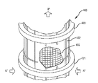
도 1은 여과 시스템의 공기 오염 제어 필터 요소의 실시예의 단면도의 개략적인 다이어그램.
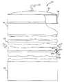
도 2a는 여과 시스템용 공기 오염 제어 필터 요소의 실시예의 부분 단면도.
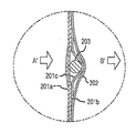
도 2b는 도 2a의 공기 오염 제어 필터 요소의 실시예의 섹션의 단면도.
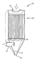
도 3은 도 2a 및 도 2b의 공기 오염 제어 필터 요소를 구비할 수 있는 여과 시스템용 백하우스의 개략도.
도 4는 여과 시스템용 공기 오염 제어 필터 요소의 실시예의 개략도.
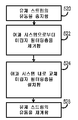
도 5a는 오염 물질 함유 유체 스트림의 미립자 필터링 및 오염 물질 정화 방법의 흐름도.
도 5b는 필터 장치의 미립자 필터링층을 교체하는 방법의 흐름도.
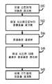
도 5c는 필터 장치의 정화층을 재생하는 방법의 흐름도.1 is a schematic diagram of a cross-sectional view of an embodiment of an air pollution control filter element of a filtration system;
2A is a partial cross-sectional view of an embodiment of an air pollution control filter element for a filtration system.
FIG. 2B is a cross-sectional view of a section of an embodiment of the air pollution control filter element of FIG. 2A. FIG.
3 is a schematic representation of a baghouse for a filtration system that may include the air pollution control filter element of FIGS. 2A and 2B.
4 is a schematic representation of an embodiment of an air pollution control filter element for a filtration system.
5A is a flow chart of a method of particulate filtering and contaminant purification of a contaminant containing fluid stream.
5b is a flow chart of a method of replacing a particulate filtering layer of a filter device.
5C is a flowchart of a method for regenerating a purification layer of a filter device.
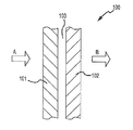
도 1은 여과 시스템용 공기 오염 제어 필터 요소(100)의 실시예의 단면도의 개략적인 다이어그램이다. 공기 오염 제어 필터 요소(100)는 2개의 부분, 즉 상류측 요소(101) 및 하류측 요소(102)를 포함할 수 있다. 상류측 요소(101)와 하류측 요소(102) 사이에는 도 1에 도시되어 있는 바와 같은 간극(103)이 존재할 수 있다. 다른 실시예에서, 상류측 요소(101) 및 하류측 요소(102)는 이들이 공기 오염 제어 필터 요소(100)의 적어도 일부분을 따라 서로 접촉하도록 위치될 수 있다.1 is a schematic diagram of a cross-sectional view of an embodiment of an air pollution
상류측 요소(101) 및 하류측 요소(102)는 서로로부터 분리 가능할 수도 있다. 예를 들어, 하류측 요소(102)는 공기 오염 제어 필터 요소(100)로부터 제거되도록 작동 가능할 수도 있다. 제거 후에, 하류측 요소(102)는 교체용 상류측 요소(101)에 인접하여 설치되도록 작동 가능할 수도 있다. 유사하게, 상류측 요소(101)는 공기 오염 제어 필터 요소(100)로부터 제거되고 이후에 교체용 하류측 요소(102)에 인접하여 설치되도록 작동 가능할 수도 있다. 더욱이, 하류측 요소(102)는 공기 오염 제어 필터 요소(100)로부터 제거된 후에 유지보수되도록 작동 가능할 수도 있다. 유지보수(이하에 설명됨) 후에, 하류측 요소(102)는 상류측 요소(101)에 인접하여 공기 오염 제어 필터 요소(100) 내에 재차 설치될 수 있다.The
공기 오염 제어 필터 요소(100)는 오염 물질 함유 유체 스트림(A)으로부터 오염 물질을 제거하도록 작동 가능할 수도 있다. 오염 물질 함유 유체 스트림(A)은 산업 프로세스로부터의 오염 물질 함유 가스의 스트림일 수 있다. 예를 들어, 오염 물질 함유 유체 스트림(A)은 예를 들어 금속 제조 설비로부터의 연소 연도 가스의 스트림일 수 있다.The air pollution
오염 물질 함유 유체 스트림(A)은 특히 미립자 및 화학 오염 물질을 포함할 수 있다. 예를 들어, 오염 물질 함유 유체 스트림(A)은 재 미립자를 포함할 수 있다. 오염 물질 함유 유체 스트림(A)은 다이옥신, 퓨란, 수은 및/또는 NOx와 같은 오염 물질을 포함할 수 있다. 특히, 수은이 오염 물질 함유 유체 스트림(A) 내에 존재할 수 있다.The contaminant containing fluid stream (A) may in particular comprise particulates and chemical contaminants. For example, the pollutant containing fluid stream A may comprise ash particulates. The contaminant containing fluid stream A may comprise contaminants such as dioxin, furan, mercury and / or NO x . In particular, mercury may be present in the pollutant containing fluid stream (A).
공기 오염 제어 필터 요소(100)의 상류측 요소(101)는 일반적으로 오염 물질 함유 유체 스트림(A)으로부터 미리 결정 가능한 크기의 미립자를 제거하도록 구성될 수 있다. 예를 들어, 일 구성에서, 상류측 요소(101)는 0.5 인치 물 게이지의 차압에서 측정된 2 cfm/ft2 초과의 공기 투과도 및 0.3 미크론(5.3 cm/s)에서 80% 초과의 여과 효율을 가질 수 있다. 상류측 요소(101)는 단일층을 포함할 수 있거나 또는 하나 이상의 서브층을 포함할 수 있다. 예를 들어, 상류측 요소(101)는 파이버글래스 백킹에 라미네이팅된 ePTFE 멤브레인을 포함할 수 있다. ePTFE 멤브레인은 상류측 요소(101)의 상류측[도 1에 도시되어 있는 바와 같이 상류측 요소(101)의 좌측]에 위치될 수 있고, 반면 파이버글래스 백킹은 상류측 요소(101)의 하류측[도 1에 도시되어 있는 바와 같이 상류측 요소(101)의 우측]에 위치될 수 있다. 이러한 시스템에서, 파이버글래스 백킹은 일반적으로 ePTFE 멤브레인을 위한 지지체로서 기능할 수 있다. 여과 중에, 미립자는 일반적으로 ePTFE 멤브레인의 상류측 표면 상에 먼지 케이크를 형성할 수 있다. 이 먼지 케이크는 이하에 설명되는 역방향 공기 여과 시스템에 사용되는 바와 같은 세척 프로세스에 의해 제거될 수 있다.The
하류측 요소(102)는 일반적으로 오염 물질 함유 유체 스트림(A)으로부터 화학 물질과 같은 추가의 오염 물질을 제거하도록 구성될 수 있다. 하류측 요소(102)는 특정 오염 물질을 위해 구성될 수 있다.The
하류측 요소(102)는 오염 물질을 포획하기 위한 결합제 및/또는 오염 물질을 더 바람직한 상태로 분해하거나 변형시키도록 작동 가능한 촉매제를 포함할 수 있다. 하류측 요소(102)는 특정 오염 물질과 반응하도록 설계된 촉매를 포함할 수 있다. 하류측 요소는 귀금속, 천이 금속 산화물, 뿐만 아니라 알칼리 및 알칼리 토금속, 이들의 산화물 및 카보네이트와 같은 촉매 재료를 포함할 수 있다. 바람직한 촉매는 귀금속(예를 들어, Pt, Pd, Au, Ag, Ir 및 Rh와 이들의 화합물), 바나디아 및/또는 천이 금속(예를 들어, Fe, Cu 및 Al과 이들의 화합물)으로부터 선택된, 큰 표면적을 갖는 티타니아, 알루미나, 실리카 및 제올라이트와 같은 입자를 그 위에 포함할 수 있다. 특히 바람직한 촉매는 이산화티타늄의 아나타제(anatase) 형태의 V2O5를 포함한다. 하류측 요소는 촉매 직물 및/또는 촉매 펠트의 형태일 수 있다.The
하류측 요소(102)는 오염 물질 함유 유체 스트림(A)으로부터 오염 물질을 흡착하고 이에 의해 오염 물질들을 제거하기 위한 흡착성 성분을 포함할 수 있다. 예를 들어, 하류측 요소(102)는 활성탄을 포함할 수 있다. 활성탄은 노볼로이드 파이버 및/또는 노볼락로부터 생성된 파이버의 형태일 수 있다. 이와 관련하여, 하류측 요소 자체는 흡착성 재료로부터 구성될 수 있다. 노볼락 및 노볼로이드 파이버는 가교 결합된 3차원 페놀릭-알데히드 파이버이다. 이들 파이버는 공지의 기술을 사용하여 활성화되어 활성탄 파이버를 생성할 수 있다. 노볼락/노볼로이드 탄소 파이버 활성화의 예시적인 프로세스는 바타 등의 미국 특허 제4,076,692호에서 발견될 수 있다. 상표명 카이놀TM 하에서 입수 가능한 이러한 활성탄은 가스 스트림으로부터 수은을 흡착하는 데 특히 효과적이다.The
다른 예에서, 흡착성 입자의 형태의 흡착성 성분은 하류측 요소(102) 내에 포함될 수 있다. 구체적으로, 하류측 요소(102)는 폴리머 접착제에 의해 하류측 요소(102)의 다공성 직조 또는 부직조 기판에 그리고 선택적으로 적어도 하나의 보호 미공성층인 기판에 인접하여 또는 기판 내에 접착되는 흡착성 입자를 포함할 수 있다. 특정 구성에서, 다공성 기판은 직조 또는 부직조 ePTFE 파이버를 포함한다. 본 명세서에 사용될 때, 용어 "폴리머 접착제"는 기판에 흡착성 입자를 속박하는 스트링 및 분산 주요 입자를 형성하는 것이 가능한 액체 내에 부유하는 고체 입자의 형태, 뿐만 아니라 폴리머 접착제의 최종 고정된 형태의 적어도 하나의 열가소성 엘라스토머를 포함할 수 있다. 적합한 폴리머 접착제는 PTFE, 플로우로에틸렌 프로필렌, 고분자량 폴리에틸렌(즉, 분자량이 백만 이상인 경우), 고분자량 폴리프로필렌(즉, 분자량이 백만 이상인 경우), 퍼플루오로아크릴레이트, 폴리비닐리덴 플루오라이드, 테트라플루오로에틸렌의 3원 공중합체, 헥사플루오로프로필렌 및 비닐리덴 플루오라이드 및 폴리크롤로 트리플루오로 에틸렌을 포함한다. 흡착성 입자는 활성탄 입자를 포함할 수 있다. 본 명세서에 그대로 참조로서 포함되어 있는 워터스(Waters) 등의 미국 특허 제6,331,351호는 폴리머 접착제를 사용하여 다공성 직조 또는 부직조 기판에 접착된 입자를 포함하는 필터 재료의 제조 및 구성을 설명하고 있다.In another example, the adsorbent component in the form of adsorbent particles may be included in the
일 구성에서, 전술된 촉매제는 흡착성 입자에 대해 설명되어 있는 것과 유사한 방식으로 폴리머 접착제를 사용하여 다공성 직조 또는 부직조 기판에 접착될 수 있다. 일 구성에서, 흡착성 및 촉매 입자 모두는 폴리머 접착제를 사용하여 기판에 접착될 수 있다.In one configuration, the catalyst described above may be attached to the porous woven or nonwoven substrate using a polymer adhesive in a similar manner as described for the adsorbent particles. In one configuration, both adsorbent and catalyst particles can be adhered to the substrate using a polymer adhesive.
상류측 요소(101) 및 하류측 요소(102)는 서로 상이한 수명 사이클 기간을 가질 수 있다. 예를 들어, 하류측 요소(102)는 촉매 펠트일 수 있고, 상류측 요소(101)의 하류측의 그 위치에 의해 미립자 필터링을 거의 또는 전혀 수행하지 않을 수 있다. 따라서, 하류측 요소(102)의 수명 사이클은 하류측 요소(102) 내의 촉매 재료의 수명 사이클에 기초할 수 있고, 따라서 상류측 요소(101) 내에 사용된 통상의 미립자 필터보다 몇 배 더 긴 사용 수명을 가질 수 있다. 더욱이, 하류측 요소(102)는 상류측 요소(101)보다 제조 비용이 상당히 더 높을 수 있다.The
실시예에서, 하류측 요소(102)는 상류측 요소(101)에 영구적으로 상호 연결될 수 있다. 대안으로, 하류측 요소(102)는 상류측 요소(101)에 대해 제거 가능하게 배치될 수 있다. 상류측 요소(101)에 대해 제거 가능하게 배치된 하류측 요소(102)를 가져 상류측 요소(101) 및 하류측 요소(102)의 사용 수명 사이클이 분리될 수 있게 하는 것이 유리할 수 있다. 일단 분리되면, 각각의 개별 요소는 전체 효율을 최대화하고 공기 오염 제어 필터 요소(100)의 작동의 전체 비용을 감소시키도록 구성될 수 있다.In an embodiment, the
특히, 예를 들어 하류측 요소(102)가 상류측 요소(101)보다 상당히 고가이면, 상류측 요소(101)는 더 고가인 하류측 요소(102)의 수명 기간을 최대화하도록 구성될 수 있다. 예를 들어, 이는 하류측 요소(102)에 도달하는 것으로부터 하류측 요소(102)의 효용성을 감소시킬 수 있는 미립자를 거의 또는 전혀 생성하지 않는 미립자 여과 효율을 갖도록 상류측 요소(101)를 구성함으로써 성취될 수 있다. 이와 관련하여, 하류측 요소(102)는 하류측 요소(102)의 촉매 또는 흡착성 특성의 사용 수명과 동일한 사용 수명을 가질 수 있다. 이러한 상류측 요소(101)의 특정 여과 효율은 오염 제어 규제에 의해 요구되는 것보다 클 수 있지만, 언급된 바와 같이 상류측 요소(101)보다 더 고가일 수 있는 하류측 요소(102)의 증가된 수명에 기인하여 공기 오염 제어 필터 요소(100)의 작동 비용에 대해 여전히 유리할 수 있다. 이와 관련하여, 상류측 요소(101)가 그 사용 수명을 완료할 때, 상류측 요소는 하류측 요소(102)로부터 분리되어 하류측 요소(102)와 독립적으로 교체될 수 있다. 따라서, 상류측 요소(101)의 상류측에 라미네이팅된 ePTFE 층은, 상류측 요소(101)가 미립자를 필터링하여 폐색 및/또는 미립자 축적에 의해 하류측 요소(102)의 작동 수명이 제한되지 않고 단지 촉매 또는 흡착성 성분의 수명 사이클에 의해 제한되도록 그 여과 효율이 선택될 수 있기 때문에 유리할 수 있다.In particular, if, for example, the
하류측 요소(102)는 재생 가능할 수 있다(예를 들어, 재생 프로세스를 통해 재생되도록 작동 가능함). 본 명세서에 사용될 때, "재생 프로세스"는 하류측 요소(102)와 같은 공기 오염 제어 요소의 촉매 활동도 또는 흡착성 용량이 적어도 부분적으로 복원되는 프로세스이다. 흡착성 용량이 적어도 부분적으로 복원되는 경우에, 재생 프로세스는 공기 오염 제어 요소로부터 오염 물질이 분리되게 할 수 있다. 이러한 분리는 공기 오염 제어 요소로부터의 오염 물질 탈착의 형태를 취할 수 있다. 이러한 분리는 공기 오염 제어 요소의 작동 온도보다 높은 온도에서 가열된 가스로의 노출을 통해 성취될 수 있다. 이러한 재생 프로세스는 공기 오염 제어 요소가 복원되게 할 수 있어 그 원래 오염 물질 흡착 용량의 적어도 약 50%를 갖게 할 수 있다.The
재생 프로세스는 분리된 오염 물질을 수집하는 것을 포함할 수 있다. 예를 들어, 오염 물질은 가열된 가스에 대한 노출 중에 공기 오염 제어 요소로부터 탈착될 수 있고, 이들 오염 물질은 수집될 수 있고(예를 들어, 가열된 가스에 공기 오염 제어 요소를 노출하는 데 사용되는 오븐에 결합된 필터에 의함) 공기 오염 제어 요소로부터 개별적으로 취급된다(예를 들어, 폐기됨). 이와 관련하여, 오염 물질은 제1 설비(예를 들어, 여과 시스템이 위치되어 있음)에서 수집되고(예를 들어, 공기 오염 제어 요소에 의해 흡착됨), 공기 오염 제어 요소와 결합되면서 제2 설비(예를 들어, 탈착 오븐이 위치되어 있음)로 운반될 수 있고, 오염 물질의 적어도 일부는 탈착되고 폐기를 위해 제2 설비에서 수집될 수 있다.The regeneration process may include collecting the separated contaminants. For example, contaminants can be desorbed from the air pollution control element during exposure to heated gas, and these pollutants can be collected (eg used to expose the air pollution control element to the heated gas). By means of a filter coupled to an oven) (eg, discarded) from the air pollution control element. In this regard, contaminants are collected in a first plant (eg, where a filtration system is located) (eg, adsorbed by an air pollution control element) and combined with an air pollution control element while the second plant (Eg, a desorption oven is located) and at least some of the contaminants may be desorbed and collected at a second facility for disposal.
하류측 요소(102)는 상류측 요소(101)로부터 분리되어 재생 프로세스를 거치게 될 수 있다. 재생 프로세스는 하류측 요소(102)를 미리 결정된 온도에서 미리 결정된 기간 동안 오븐 내에 배치하여 흡착된 오염 물질이 하류측 요소(102)로부터 탈착되게 하는 것을 포함할 수 있다.The
이하의 실험은 노볼락 파이버로부터 제조된 활성탄의 직물의 수은 흡착 및 탈착 용량을 정량화하기 위해 수행되었다. 실험은 노볼락 파이버로부터 제조된 활성탄의 직물의 5/8" 직경 샘플을 이용하였다. 샘플은 N2, 공기 및 SO2를 함유하는 가스 스트림 내에서 24시간 동안 수은 증기에 노출되었다. 샘플을 통하는 총 가스 유량은 211 분당 입방 센티미터(cc/min)였다. 유동 제어는 130 cc/min의 질소, 80 cc/min의 공기 및 1 cc/min의 SO2에서 유지되었다. 수은 증기는 76℃ 수욕(water bath) 내에 위치된 투과 튜브로부터 가스 스트림 내에 배출되었다. 샘플은 튜브로(tube furnace) 내에서 노출 중에 150℃로 가열되었다. 수은 레벨은 노출량을 검증하기 위해 수은 분광계로의 연속적인 모니터링을 사용하여 측정되었다. 다양한 스테이지에서, 샘플은 흡착된 수은 레벨을 결정하기 위해 분광계로 측정되었다. 이러한 결정은 샘플의 파괴를 요구하기 때문에, 실험은 동일한 조건을 거친 다수의 샘플로 시작되어 수행되었고, 개별 샘플은 실험의 다양한 스테이지에서 파괴식으로 시험되었다. 수은 증기로의 최초 24시간 노출 후에, 제1 샘플은 분광계로 측정되었고 12,358 백만분율(ppm)의 수은을 포함하는 것으로 발견되었다. 나머지 샘플은 이어서 공기 내에서 2시간 동안 300℃에서 오븐 내에서 탈착되었다. 제2 샘플은 분광계로 측정되었고 731 ppm의 수은을 포함하는 것으로 발견되었다. 나머지 샘플은 이어서 원래 노출과 동일한 방식으로 24시간 동안 재노출되었다. 제3 샘플은 이어서 분광계를 사용하여 분석되었고 11,016 ppm의 수은을 포함하는 것으로 발견되었다.The following experiments were performed to quantify the mercury adsorption and desorption capacity of fabrics of activated carbon made from novolac fibers. The experiment used a 5/8 "diameter sample of a fabric of activated carbon made from a novolac fiber. The sample was exposed to mercury vapor for 24 hours in a gas stream containing N 2 , air and SO 2 . The total gas flow rate was 211 cubic centimeters per minute (cc / min) Flow control was maintained at 130 cc / min of nitrogen, 80 cc / min of air and 1 cc / min of SO 2 Mercury vapors were maintained at 76 ° C. in a water bath ( The gas stream was discharged from a permeate tube placed in a water bath.The sample was heated to 150 ° C. during exposure in a tube furnace.The mercury level used continuous monitoring with a mercury spectrometer to verify the exposure. At various stages, the samples were measured with a spectrometer to determine the level of adsorbed mercury, since this determination required the destruction of the sample, so the experiments were subjected to multiple samples with the same conditions. The individual samples were tested destructively at various stages of the experiment.After the first 24 hours of exposure to mercury vapor, the first sample was measured with a spectrometer and contained 12,358 parts per million (ppm) of mercury. The remaining sample was then desorbed in air for 2 hours in an oven at 300 ° C. The second sample was measured with a spectrometer and was found to contain 731 ppm of mercury The remaining sample was then in the same manner as the original exposure. The sample was then analyzed using a spectrometer and found to contain 11,016 ppm of mercury.
도 2a는 역방향 공기 여과 시스템용 공기 오염 제어 필터 요소(200)의 실시예의 부분 단면도이다. 공기 오염 제어 필터 요소(200)는 일반적으로 얇은벽 실린더의 형태이다. 실린더의 저부 단부는 오염 물질 함유 유체 스트림(A')에 기능적으로 연결되도록 작동 가능하다. 오염 물질 함유 유체 스트림(A')은 공기 오염 제어 필터 요소(200)의 내부 부분 내로 유동하고 이어서 실린더의 벽을 통해 외향으로 유동할 수 있어 오염 물질 함유 유체 스트림(A')을 필터링하여 이에 의해 필터링된 유체 스트림(B')을 생성한다. 오염 물질 함유 유체 스트림(A')은 도 2a에 도시되어 있는 바와 같이 실린더로부터 유동할 수 있다. 실린더의 상부 단부는 공기 오염 제어 필터 요소(200)를 지지하고 그를 통한 유체 스트림 유동을 방지하는 데 사용된 캡(207)을 포함할 수 있다.2A is a partial cross-sectional view of an embodiment of an air pollution
도 2b는 도 2a의 공기 오염 제어 필터 요소(200)의 섹션의 단면도이다. 도 2b에 도시되어 있는 바와 같이, 오염 물질 함유 유체 스트림(A')은 실린더의 내부(도 2b의 좌측에 위치됨)로부터 공기 오염 제어 필터 요소(200)의 층을 통해, 이에 의해 오염 물질을 제거하여, 필터링된 유체 스트림(B')으로서 실린더로부터 나와 실린더의 외부(도 2b의 우측에 위치됨)로 유동한다.FIG. 2B is a cross-sectional view of a section of the air pollution
공기 오염 제어 필터 요소(200)의 층은 도 1의 필터 요소(100)를 참조하여 전술되어 있는 바와 유사하게 구성될 수 있다. 이와 관련하여, 상류측 요소는 제1 층(201a) 및 제2 층(201b)을 포함할 수 있다. 제1 층(201a) 및 제2 층(201b)은 함께 상류측 요소(201)를 형성한다. 하류측 요소(202)는 상류측 요소(201)의 하류측에 위치될 수 있다. 기능적으로, 오염 물질 함유 유체 스트림(A')은 제1 층(201a) 내로 통과하고, 오염 물질 함유 유체 스트림(A') 내의 미립자는 유체 스트림으로부터 필터링된다. 제1 층(201a)은 미리 결정될 수 있는 여과 효율의 ePTFE 층일 수 있다. 예를 들어, 제1 층(201a)은 0.5 인치 물 게이지의 차압에서 측정된 2 cfm/ft2 초과의 공기 투과도 및 0.3 미크론(5.3 cm/s)에서의 80% 초과의 여과 효율을 가질 수 있다. 제1 층(201a)은 제2 층(201b)에 의해 지지될 수 있다. 제2 층(201b)은 파이버글래스 직물 백킹을 포함할 수 있다. 유체 스트림으로부터 필터링된 미립자는 일반적으로 제1 층(201a)의 상류측 표면 상에 퇴적될 수 있다.The layer of air pollution
상류측 요소(201)를 통과한 후에, 유체 스트림은 이어서 하류측 요소(202)를 통과한다. 하류측 요소(202)는 도 1의 하류측 요소(102)를 참조하여 전술된 바와 유사하게 구성될 수 있다. 이와 관련하여, 하류측 요소(202)는 하류측 요소(102)를 참조하여 설명되어 있는 것들과 같은 촉매 성분 및/또는 흡착성 성분을 포함할 수 있다.After passing through the upstream element 201, the fluid stream then passes through the
하류측 요소(202)는 상류측 요소(201)로부터 분리 가능할 수 있다. 이와 관련하여, 하류측 요소(202) 및/또는 상류측 요소(201)는 각각 개별적으로 교체 가능할 수도 있다.The
도 2a로 복귀하면, 공기 오염 제어 필터 요소(200)는 공기 오염 제어 필터 요소(200)의 종축을 따라 개시된 복수의 지지 부재를 포함할 수 있다. 지지 부재는 지지 링(203)과 같은 지지 링의 형태일 수 있다. 지지 링(203)은 공기 오염 제어 필터 요소(200)의 상류측 요소(201)에 부착된 금속(또는 임의의 다른 적절한 재료) 링의 형태일 수 있다. 도 2b에 도시되어 있는 바와 같이, 지지 링(203)은 보강부(201c)와 제2 층(201b) 사이에 지지 링(203)을 배치함으로써 상류측 요소(201)에 체결될 수 있다. 보강부(201c)는 이어서 제2 층(201b)에 봉합되어 지지 링(203)이 상류측 요소(201b)에 대해 적소에 유지되게 한다. 보강부(201c)는 상류측 요소(201)와 유사하게 구성될 수 있다. 따라서, 지지 링(203) 및 다른 유사하게 구성된 지지 링은 공기 오염 제어 필터 요소(200)에 지지를 제공할 수 있어, 필터 요소(200)의 외부의 압력이 예를 들어 세척 사이클 중에 필터 요소(200)의 내부의 압력보다 클 때 공기 오염 제어 필터 요소(200)가 그 자체로 붕괴되는 것을 방지할 수 있다.Returning to FIG. 2A, the air pollution
도 2a로 복귀하면, 공기 오염 제어 필터 요소(200)는 공기 오염 제어 필터 요소(200)의 저부에 배치된 내연마성 직물 커프(204)를 더 포함할 수 있다. 커프(204)는 튜브 시트와 면을 접하는 공기 오염 제어 필터 요소(200)에 추가의 강도를 제공할 수 있다.Returning to FIG. 2A, the air pollution
하류측 요소(202)의 상부 부분(205)은 캡(207)의 부착 부재(206)에 상호 연결되도록 작동 가능할 수 있다. 이러한 상호 연결은 임의의 적절한 방식으로 성취될 수 있다. 예를 들어, 도 2a에 도시되어 있는 바와 같이, 부착 부재(206)는 원주형 리지(ridge)의 형태일 수 있다. 하류측 요소(202)는 하류측 요소(202)의 상부 부분 내에 봉합된 금속 밴드와 같은 강성 밴드를 포함할 수 있다. 강성 밴드는 부착 부재(206)의 외경보다 작은 내경을 갖도록 치수 설정될 수 있다. 따라서, 하류측 요소(202)는 상류측 요소(201)의 전체 길이에 걸쳐 걸쳐지고 부착 부재(206) 바로 위에 위치된 강성 밴드에 의해 현수될 수 있다. 따라서, 강성 밴드는 부착 부재(206) 아래로 하향으로 이동하는 것이 불가능할 수 있다. 하류측 요소(202)는 또한 공기 오염 제어 필터 요소(200)의 저부를 따라 임의의 적절한 방식으로 상류측 요소(201)에 상호 연결될 수 있다. 예를 들어, 고정 클램프가 상류측 요소(201) 및 하류측 요소(202) 모두를 튜브 시트(302)의 관통 구멍에 클램프하는 데 사용될 수 있다(도 3, 이하에 설명됨).The
부착 부재(206)는 캡(207)에 상호 연결되거나 캡(207)의 부분일 수 있다. 행어(hanger)(208)가 캡(207)에 상호 연결될 수 있다. 이와 관련하여, 전체 공기 오염 제어 필터 요소(200)는 행어(208)로부터 현수될 수 있다.
전술된 바와 같이, 하류측 요소(202)는 상류측 요소(201)로부터 분리 가능할 수 있다. 이는 하류측 요소(202) 또는 상류측 요소(201)의 개별적인 교체를 허용할 수 있다. 예를 들어, 전술된 바와 같이, 하류측 요소(202)는 상류측 요소(201)보다 상당히 긴 사용 수명을 가질 수 있고, 따라서 하류측 요소(202)를 유지하면서 상류측 요소(201)를 교체하는 것이 바람직할 수 있다.As described above, the
상류측 요소(201)를 교체하기 위한 예시적인 프로세스에서, 제1 단계는 오염 물질 함유 유체 스트림(A')의 유동을 일시적으로 중지시키는 것일 수 있다. 다음 단계는 행어(208)에서 이를 후크 결합 해제하고 튜브 시트(302)(도 3)로부터 저부에서 공기 오염 제어 필터 요소(200)를 분리함으로써 공기 오염 제어 필터 요소(200)를 분리하는 것일 수 있다. 다음에, 하류측 요소(202)는 상류측 요소(201)의 저부로부터 분리되고 캡(207) 상에서 이를 미끄러지게 함으로써 공기 오염 제어 필터 요소(200)로부터 미끄럼 제거될 수 있다. 다음에, 상류측 요소(201)는 캡(207)으로부터 제거될 수 있다. 새로운 상류측 요소(201)가 이어서 캡(207)에 상호 연결될 수 있다. 다음에, 하류측 요소(202)는 캡(207) 및 새로운 상류측 요소(201) 상에서 미끄러질 수 있고, 이어서 새로운 상류측 요소(201)의 저부에 상호 연결될 수 있다. 공기 오염 제어 필터 요소(200)는 이어서 재설치될 수 있고, 오염 물질 함유 유체 스트림(A')의 유동이 재시작될 수 있다.In an exemplary process for replacing upstream element 201, the first step may be to temporarily stop the flow of contaminant containing fluid stream A ′. The next step may be to separate the air pollution
전술된 바와 같이, 공기 오염 제어 필터 요소(200)가 역방향 기류 여과 시스템 내에 설치되도록 작동 가능할 수 있다. 이러한 역방향 기류 여과 시스템의 예는 도 3에 도시되어 있다. 역방향 기류 여과 시스템은 백하우스(300) 및 복수의 개별 공기 오염 제어 필터 요소(303)를 포함할 수 있다. 각각의 개별 공기 오염 제어 필터 요소는 도 2a의 공기 오염 제어 필터 요소(200)와 유사하게 구성될 수 있다. 예시의 목적으로, 단지 4개의 공기 오염 제어 필터 요소(303)만이 도 3에 도시되어 있다. 그러나, 실제로 백하우스는 수십개의 개별 공기 오염 제어 필터 요소를 포함할 수 있다. 백하우스(300)는 오염 물질 함유 유체 스트림(A')을 공급할 수 있는 입구(301)를 포함할 수 있다. 유체 스트림은 백하우스(300)를 통과하고 백하우스(300)의 상부에서 출구(304)를 통해 필터링된 유체 스트림(B')으로서 나타날 수 있다.As mentioned above, the air pollution
백하우스(300)는 다양한 산업 프로세스로부터 생성된 오염 물질 함유 유체 스트림으로부터 오염 물질을 필터링하는 데 사용될 수 있다. 이러한 유체 스트림은 금속 생성 프로세스로부터의 연소 연도 가스의 형태일 수 있다. 다른 제조 및/또는 화학 프로세서로부터의 유체 스트림이 또한 백하우스(300)를 통해 필터링될 수 있다.
공기 오염 제어 필터 요소(303)가 백하우스(300) 내에 설치될 수 있다. 이러한 설치에서, 각각의 공기 오염 제어 필터 요소(303)는 행어(208)를 사용하여 백하우스(300)의 지지 부재(307)에 후크 결합될 수 있다. 도 3에는 단일의 수평 바아로서 도시되어 있지만, 지지 부재(307)는 행어(208)와 면을 접하기 위해 임의의 적절한 형태를 취할 수 있다. 예를 들어, 지지 부재는 복수의 공기 오염 제어 필터 요소(303)가 그리드 패턴으로 위치될 수 있게 하는 부착점의 그리드의 형태일 수 있다. 공기 오염 제어 필터 요소(303)의 저부 단부는 백하우스(300)의 튜브 시트(302)에 상호 연결될 수 있다. 튜브 시트(302)는 각각의 개별 공기 오염 제어 필터 요소(303) 내에 오염 물질 함유 유체 스트림(A')을 유도하는 복수의 오리피스(308)를 포함할 수 있다. 튜브 시트(302)는 또한 각각의 공기 오염 제어 필터 요소(303)를 개별적으로 고정하기 위한 구조체를 포함할 수 있어 실질적으로 어떠한 오염 물질 함유 유체 스트림(A')도 공기 오염 제어 필터 요소(303)를 우회할 수 없다.An air pollution
작동시에, 오염 물질 함유 유체 스트림(A')은 입구(301)를 통해 그리고 각각의 공기 오염 제어 필터 요소(303)의 내부 부분 내로 유도될 수 있다. 시간 경과에 따라 미립자는 각각의 공기 오염 제어 필터 요소(303)의 내부면 상에 수집될 수 있다. 때때로, 수집된 미립자를 제거하는 것이 바람직할 수 있다. 이는 역방향 공기 세척 사이클에 의해 성취될 수 있다. 역방향 공기 세척 사이클은 백하우스(300) 내로의 오염 물질 함유 유체 스트림(A')의 유동의 일시 중지를 포함할 수 있다. 유동이 중지되는 동안, 백하우스(300)를 통한 역방향 유동이 개시될 수 있어 공기가 출구(304)를 통해 그리고 각각의 공기 오염 제어 필터 요소(303)의 측벽을 통해 백하우스(300) 내로 도입되게 된다. 이 역방향 유동은 각각의 공기 오염 제어 필터 요소(303)의 내부면 상에 수집되어 있는 미립자를 탈락시킬 수 있다. 탈락된 미립자는 각각의 공기 오염 제어 필터 요소(303)의 길이를 따라 튜브 시트(302) 아래에 위치된 수집 부재(305) 내로 낙하될 수 있다. 수집 부재(305)는 탈락된 미립자가 백하우스(300)로부터 제거될 수 있는 개구(306)를 포함할 수 있다. 만족스러운 양의 미립자가 공기 오염 제어 필터 요소(303)로부터 탈락된 후에, 역방향 기류가 중지될 수 있고, 정규의 여과 작동이 재개될 수 있다.In operation, the pollutant containing fluid stream A 'may be directed through the
도 2a 및 도 2b의 공기 오염 제어 필터 요소(200)의 구성은 도 3의 역방향 공기 백하우스(300)와 같은 역방향 공기 백하우스에 사용되는 바와 같이, 상류측 요소(201)보다 상당히 덜 강한 하류측 요소(202)를 수용하도록 작동 가능할 수도 있다. 이와 관련하여, 상류측 요소(201)는 하류측 요소(202)를 위한 지지를 제공할 수 있다. 예를 들어, 여과 중에, 공기 오염 제어 필터 요소(200)를 가로지르는 대부분의 압력 강하는 미립자 여과가 이루어지는 상류측 요소(201)를 가로질러 발생할 수 있다. 대조적으로, 하류측 요소(202)는 상류측 요소(201)와 비교하여 비교적 높은 투과성을 가질 수 있다. 따라서, 적은 압력 강하가 하류측 요소(202)를 가로질러 발생할 수 있다. 따라서, 오염 물질 함유 유체 스트림(A')의 유동으로부터 비교적 작은 힘[상류측 요소(201)에 비교할 때]이 하류측 요소(202)에 전달될 수 있다.The configuration of the air pollution
유체 스트림의 방향이 역전되어 있는 세척 사이클 중에, 역방향 유동은 하류측 요소(202)가 상류측 요소(201)에 대해 가압될 수 있게 할 수 있다. 이러한 상황에서, 상류측 요소(201)는 하류측 요소(202)를 위한 백킹을 제공함으로써 하류측 요소(202)를 위한 기계적 지지를 제공할 수 있다. 대조적으로, 상류측 요소(201)는 이를 가로지르는 상당한 압력 강하에 기인하여, 그를 통과할 때 정상 유동 중에 오염 물질 함유 유체 스트림(A')의 힘 및 세척 중에 역방향 유동으로부터의 힘을 견디기에 충분히 강해야 한다.During the wash cycle in which the direction of the fluid stream is reversed, the reverse flow may allow the
공기 오염 제어 필터 요소(400)의 다른 실시예가 도 4에 도시되어 있다. 공기 오염 제어 필터 요소(400)는 펄스 제트 요소 세척 시스템을 구비하는 백하우스 내에 사용될 수 있다. 공기 오염 제어 필터 요소(400)에 있어서, 오염 물질 함유 유체 스트림(A")은 상류측 요소(401)를 통해 측벽을 통해 공기 오염 제어 필터 요소(400)에 진입한다. 상류측 요소는 오염 물질 함유 유체 스트림(A")으로부터의 미립자를 여과 효율의 미리 결정된 레벨로 필터링하도록 구성될 수 있다. 상류측 요소(401)는 예를 들어, 파이버글래스 백킹에 라미네이팅된 ePTFE 층을 포함할 수 있다. ePTFE 층은 상류측 요소(401)의 외부면(도 4에 도시되어 있는 바와 같이) 상에 배치될 수 있다. 상류측 요소(401)는 상류측 요소 지지 케이지(403)에 의해 붕괴되는 것이 억제될 수 있다. 유체 스트림은 이어서 하류측 요소(402)를 통과할 수 있다. 하류측 요소(402)는 촉매 및/또는 흡착성 층일 수 있다. 예를 들어, 하류측 요소(402)는 상표명 카이놀TM 하에서 입수 가능한 것과 같은 노볼로이드 및/또는 노볼락 파이버로부터 생성된 활성탄 파이버를 포함할 수 있다. 하류측 요소(402)는 하류측 요소 지지 케이지(404)에 의해 붕괴되는 것이 억제될 수 있다. 하류측 요소(402)를 통과한 후에, 유체 스트림은 필터링되어 있고 공기 오염 제어 필터 요소(400)의 상부에서 개구를 통해 공기 오염 제어 필터 요소(400)를 나올 수 있다. 공기 오염 제어 필터 요소(400)의 다른(저부) 단부는 캡핑될 수 있어 공기 오염 제어 필터 요소(400)의 내부 내로의 모든 기류가 상류측 요소(401) 및 하류측 요소(402)를 통과되게 한다.Another embodiment of an air pollution
작동시에, 미립자는 공기 오염 제어 필터 요소(400)의 외부에 먼지 케이크를 형성할 수 있다. 먼지 케이크를 제거하기 위해, 유체 펄스[예를 들어, 오염 제어 필터 요소(400)의 개방 상부 단부 상부에 위치된 제트로부터 압축된 공기의 펄스]가 개방된 상부로부터 백 내로 하향 유도될 수 있다(도 4에 도시되어 있는 유체 유동에 대향하는 방향에서). 이 펄스는 상류측 요소(401)를 팽창시키고 요동하여, 먼지 케이크를 흐트러뜨리고 따라서 미립자가 상류측 요소(401)로부터 이격 낙하하게 할 수 있다.In operation, the particulates can form a dust cake outside of the air pollution
상류측 요소(401) 및 하류측 요소(402)는 독립적으로 교체 가능할 수 있다. 예를 들어, 일단 상류측 요소(401)의 사용 수명이 완료되면, 상류측 요소(401)는 상류측 요소 지지 케이지(403)로부터 이를 미끄럼 제거함으로써 공기 오염 제어 필터 요소(400)로부터 제거될 수 있다. 새로운 상류측 요소(401)는 이어서 상류측 요소 지지 케이지(403) 상에서 미끄러질 수 있고, 전체 공기 오염 제어 필터 요소(400)는 이어서 재차 배치되어 유지보수될 수 있다. 유사하게, 하류측 요소(402)는 하류측 요소 지지 케이지(404) 및 하류측 요소(402)를 제거하고, 하류측 요소 지지 케이지(404) 주위에 새로운 하류측 요소(402)를 설치하고, 새로운 하류측 요소(402) 및 하류측 요소 지지 케이지(404)를 공기 오염 제어 필터 요소(400) 내에 재차 삽입함으로써 교체될 수 있다.The
도 4의 공기 오염 제어 필터 요소(400)의 구성은, 펄스 제트 여과 시스템에 사용되는 바와 같이, 상류측 요소(401)보다 상당히 덜 강한 하류측 요소(402)를 수용하도록 작동 가능할 수 있다. 정상 여과 중에, 하류측 요소(402)는 하류측 요소 지지 케이지(404)에 의해 지지될 수 있어, 따라서 하류측 요소(402)가 붕괴하는 것을 방지할 수 있다. 펄스 제트 세척 중에, 하류측 요소 지지 케이지(404) 및 상류측 요소 지지 케이지(403)는 하류측 요소(402)를 적소에 유지할 수 있고, 하류측 요소(402)의 높은 투과도는 하류측 요소(402)에 전달되는 펄스 제트 세척 사이클의 세척 펄스로부터 비교적 작은 힘을 생성할 수 있다. 이와 관련하여, 세척 펄스는 실질적으로 하류측 요소(402)를 통과하고 상류측 요소(401)와 상호 작용하여 상류측 요소(401)의 상류측 표면 상에 수집될 수 있는 먼지 케이크를 배출하도록 작동 가능할 수 있다. 대조적으로, 상류측 요소(401)는 이를 가로지르는 상당한 압력 강하에 기인하여, 그를 통과할 때 오염 물질 함유 유체 스트림(A")의 힘 및 세척 펄스로부터의 힘을 견디기에 충분히 강해야 한다.The configuration of the air pollution
상류측 요소 지지 케이지(403)는 원통형 그리드를 형성하기 위해 함께 용접된 금속 와이어로부터 제작될 수 있다. 와이어의 크기 및 그리드 크기는 상류측 요소 지지 케이지(403)가 상류측 요소(401)가 오염 물질 함유 유체 스트림(A")의 정상 유동 중에 붕괴하는 것을 방지할 수 있게 하도록 선택될 수 있다. 다른 적절한 재료 및 구성 방법이 상류측 요소 지지 케이지(403)의 구성에 이용될 수 있다. 유사하게, 하류측 요소 지지 케이지(404)는 원통형 그리드를 형성하기 위해 함께 용접된 금속 와이어로부터 제작될 수 있다. 와이어의 크기 및 그리드 크기는 하류측 요소 지지 케이지(404)가 하류측 요소(402)가 오염 물질 함유 유체 스트림(A")의 정상 유동 중에 붕괴하는 것을 방지할 수 있게 하도록 선택될 수 있다. 더욱이, 하류측 요소(402)는 상류측 요소(401)보다 낮은 강도를 가질 수 있고, 따라서 하류측 요소(402)에 대한 충분한 지지를 제공하기 위해 하류측 요소 지지 케이지(404)에 대해 더 작은 그리드 크기[도 4에 도시되어 있는 바와 같이, 상류측 요소 지지 케이지(403)에 대해]를 필요로 할 수 있어, 오염 물질 함유 유체 스트림(A")의 정상 유동 중에 인열되거나 파열되지 않게 된다. 다른 적절한 재료 및 구성 방법이 하류측 요소 지지 케이지(404)의 구성에 이용될 수 있다.The upstream
도 5a는 오염 물질 함유 유체 스트림의 미립자를 필터링하고 오염 물질을 정화하는 방법의 흐름도이다. 이 방법의 제1 단계 500은 여과 시스템에 필터 장치를 상호 연결하는 것일 수 있다. 필터 장치는 필터 장치의 제1 층이 상류측 위치(오염 물질 함유 유체 스트림의 방향에 대해)에 배치되고 제2 층은 하류측 위치에 배치되도록 배향될 수 있다. 제1 층은 미립자 필터링층일 수 있고, 제2 층은 오염 물질 정화층일 수 있다. 상호 연결은 여과 시스템의 유형에 따라 다양한 형태를 취할 수 있다.5A is a flowchart of a method of filtering and purifying contaminants in a contaminant containing fluid stream. The
예를 들어, 도 2a 내지 도 3을 참조하여 전술된 바와 같은 역방향 공기 여과 시스템에서, 상호 연결 단계는 튜브 시트 내의 개구에 필터 장치의 입구 단부를 상호 연결하는 것을 수반할 수 있다. 이러한 필터 장치는 미립자 필터백 및 미립자 필터백 둘레에 제거 가능하게 배치된 슬리브를 포함할 수 있다. 이러한 시스템에서, 미립자 필터백은 슬리브의 상류측에 배치되어 오염 물질 함유 유체 스트림의 유체 유동이 튜브 시트를 통해 미립자 필터백의 내부 내로, 미립자 필터백을 통해, 그리고 이어서 슬리브를 통해 이동하게 된다.For example, in a reverse air filtration system as described above with reference to FIGS. 2A-3, the interconnecting step may involve interconnecting the inlet end of the filter device to an opening in the tube sheet. Such a filter device may comprise a particulate filter bag and a sleeve removably disposed around the particulate filter bag. In such a system, the particulate filter bag is disposed upstream of the sleeve such that fluid flow of the contaminant-containing fluid stream moves through the tube sheet into the interior of the particulate filter bag, through the particulate filter bag, and then through the sleeve.
필터 장치가 여과 시스템에 상호 연결된 후에, 다음 단계 502는 필터 장치 내에 오염 물질 함유 유체 스트림을 유도하는 것일 수 있다. 유체 스트림이 미립자 필터링층을 통과함에 따라, 다음 단계 504는 미립자 필터링층의 상류측 표면 상의 및/또는 미립자 필터링층 내의 유체 스트림으로부터 미립자를 수집하는 것일 수 있다. 다음 단계 506은 유체 스트림이 정화층을 통해 유동함에 따라 유체 스트림 내의 오염 물질을 정화하는 것일 수 있다. 전술된 바와 같이, 이러한 정화는 오염 물질의 흡착 및/또는 촉매 반응의 형태를 취할 수 있다. 여과는 연속적인 프로세스일 수 있기 때문에, 단계 502, 504 및 506은 모두 동시에 이루어질 수 있다.After the filter device is interconnected to the filtration system, the
미립자 필터링층이 미리 결정된 상태에 접근하거나 도달함에 따라, 미립자 필터링층을 교체하는 것이 바람직할 수 있다. 이러한 미리 결정된 상태는 예를 들어 미립자 필터링층의 성능(예를 들어, 세척 후에 미립자 필터링층을 가로지르는 최대 압력 강하를 초과함)에 의해, 유지보수 시간에 의해, 및/또는 임의의 다른 적절한 수단에 의해 결정될 수 있다. 예를 들어, 역방향 공기 여과 시스템에서, 미립자 필터링층(미립자 필터백의 형태)은 입자를 축적할 수 있어 역방향 공기 세척 프로세스가 미립자 필터링층의 투과도를 허용 가능한 레벨로 복원하는 것을 불가능하게 할 수 있다.As the particulate filtering layer approaches or reaches a predetermined state, it may be desirable to replace the particulate filtering layer. This predetermined state may be determined, for example, by the performance of the particulate filtering layer (eg exceeding the maximum pressure drop across the particulate filtering layer after washing), by maintenance time, and / or by any other suitable means. Can be determined by. For example, in a reverse air filtration system, the particulate filtering layer (in the form of particulate filter bags) may accumulate particles, making it impossible for the reverse air cleaning process to restore the permeability of the particulate filtering layer to an acceptable level.
도 5b는 필터 장치의 미립자 필터링층을 교체하는 방법의 흐름도이다. 이 방법의 제1 단계 520은 오염 물질 함유 유체 스트림의 유동을 중지하는 것일 수 있다. 일단 유동이 중지되면, 다음 단계 522는 여과 시스템으로부터 미립자 필터링층을 제거하는 것일 수 있다. 예를 들어, 역방향 공기 여과 시스템에서, 단계 522는 백하우스로부터 전체 필터 장치의 제거 및 이후에 미립자 필터백(미립자 필터링층)으로부터 슬리브를 제거하는 것을 포함할 수 있다. 다른 여과 시스템에서, 정화층을 적소에 남겨두면서 미립자 필터층을 제거하는 것이 바람직할 수도 있다.5B is a flow chart of a method of replacing a particulate filtering layer of a filter device. The
미립자 필터링층이 제거된 후에, 다음 단계 524는 교체용 미립자 필터층을 여과 시스템 내에 설치하는 것일 수 있다. 역방향 공기 여과 시스템의 경우에, 단계 524는 먼저 미립자 필터백 상에 슬리브를 위치시키고 이어서 그 위에 슬리브를 갖는 미립자 필터백을 여과 시스템 내에 설치하는 형태를 취할 수 있다. 일단, 교체용 미립자 필터링층이 여과 시스템 내에 설치되어 있으면, 다음 단계 526은 오염 물질 함유 유체 스트림의 유동을 재개하는 것일 수 있다.After the particulate filtering layer is removed, the
도 5c는 필터 장치의 정화층을 재생하는 방법의 흐름도이다. 방법의 제1 단계 540은 오염 물질 함유 유체 스트림의 유동을 중지하는 것일 수 있다. 일단 유동이 중지되면, 다음 단계 542는 여과 시스템으로부터 정화층을 제거하는 것일 수 있다. 예를 들어, 역방향 공기 여과 시스템에서, 단계 542는 백하우스로부터 전체 필터 장치의 제거 및 이후에 미립자 필터백으로부터 슬리브(정화층)를 제거하는 것을 포함할 수 있다. 다른 여과 시스템에서, 미립자 필터링층을 적소에 남겨두면서 정화층을 제거하는 것이 바람직할 수도 있다.5C is a flowchart of a method for regenerating a purification layer of the filter device. The
정화층이 제거된 후에, 다음 단계 544는 정화층을 재생하는 것일 수 있다. 재생 프로세스는 제어된 환경에서 상승된 온도에 정화층을 노출시키는 것을 포함할 수 있다. 노출은 미리 결정된 시간 동안 이루어질 수 있다. 노출은 특정 조건이 부합될 때까지 수행될 수 있다. 예를 들어, 노출은 특정 오염 물질 또는 오염 물질의 그룹의 탈착의 비율이 미리 결정된 비율 미만으로 떨어질 때까지 계속될 수 있다.After the purge layer is removed, the
실시예에서, 재생 단계는 오븐 내에 슬리브를 배치하고 오염 물질 함유 유체 스트림의 온도(예를 들어, 평균 온도)에 비해 높은 탈착 온도에 슬리브를 노출시키는 것을 포함할 수 있다. 탈착 온도는 오염 물질 함유 유체 스트림의 온도를 적어도 약 30℃ 초과할 수 있다. 탈착 온도는 적어도 약 180℃일 수 있다. 탈착 온도로의 슬리브의 노출은 적어도 약 60분의 지속시간을 가질 수 있다. 정화 단계는 유체 스트림으로부터 수은을 제거하는 것을 포함할 수 있고, 재생 단계는 슬리브로부터 수은을 탈착하는 것을 포함할 수 있다. 예를 들어, 정화층이 노볼락 및/또는 노볼로이드 파이버로부터 생성된 활성탄 파이버를 포함하는 흡착성 재료를 포함하는 경우에, 재생 프로세스는 60분 동안 공기의 존재에서 180℃ 오븐 내에 정화층을 배치하는 것을 포함할 수 있다.In an embodiment, the regenerating step may include placing the sleeve in an oven and exposing the sleeve to a high desorption temperature relative to the temperature (eg, average temperature) of the contaminant containing fluid stream. The desorption temperature may exceed the temperature of the contaminant containing fluid stream at least about 30 ° C. Desorption temperature may be at least about 180 ° C. Exposure of the sleeve to the detachment temperature may have a duration of at least about 60 minutes. The purifying step can include removing mercury from the fluid stream, and the regenerating step can include desorbing mercury from the sleeve. For example, where the purifying layer comprises an adsorbent material comprising activated carbon fibers produced from novolac and / or novoloid fibers, the regeneration process may require placing the purifying layer in a 180 ° C. oven in the presence of air for 60 minutes. It may include.
정화층이 재생된 후에, 다음 단계 546은 여과 시스템 내에 정화층을 설치하는 것일 수 있다. 역방향 공기 여과 시스템의 경우에, 단계 546은 먼저 미립자 필터백 상에 슬리브의 형태의 정화층을 위치시키고 이어서 그 위에 슬리브를 갖는 미립자 필터백을 여과 시스템 내에 설치하는 형태를 취할 수 있다. 일단, 필터 장치가 여과 시스템 내에 설치되어 있으면, 다음 단계 528은 오염 물질 함유 유체 스트림의 유동을 재개하는 것일 수 있다.After the purification layer is regenerated, the
도 5c의 방법은 복수회 반복될 수 있다. 이와 관련하여, 정화층은 흡착, 재생 및 재흡착의 다수의 사이클을 거치게 될 수 있다.The method of FIG. 5C may be repeated multiple times. In this regard, the purification layer may be subjected to multiple cycles of adsorption, regeneration and resorption.
전술된 재생 프로세스는 여과 시스템의 단일의 정화층을 제거하고, 재생하고, 교체하는 것을 수반한다. 다른 실시예에서, 프로세스는 제거되는 정화층(제1 정화층)이 설치되는 정화층이 아니도록 수정될 수도 있다. 예를 들어, 정화층 유지보수 동안의 설비 정지 시간을 감소시키기 위해, 이전에 재생된 정화층(제2 정화층)이 사용될 수 있다. 이러한 프로세스에서, 제2 정화층은 제1 정화층의 제거 직후에 설치될 수 있다. 제1 정화층은 이어서 재생되고 동일한 여과 시스템 내에서의 이후의 설치 및 재사용 또는 다른 여과 시스템 내에서의 재사용을 위한 준비가 될 수 있다.The regeneration process described above involves removing, regenerating, and replacing a single purge layer of the filtration system. In another embodiment, the process may be modified such that it is not a purification layer in which the purification layer (first purification layer) to be removed is installed. For example, a previously reclaimed purge layer (second purge layer) can be used to reduce equipment downtime during purge layer maintenance. In this process, the second purification layer can be installed immediately after removal of the first purification layer. The first purification layer may then be regenerated and ready for subsequent installation and reuse in the same filtration system or for reuse in another filtration system.
이와 관련하여, 정화층 재생 서비스 공급자는 재생 단계(544)를 수행할 수 있다. 예를 들어, 정화층 재생 서비스 공급자는 고객(예를 들어, 여과 시스템의 조작자)에게 교체용 정화층을 제공할 수 있다. 고객은 이어서 현존하는 정화층을 교체용 정화층으로 교체하고 사용된 정화층을 재생을 위해 정화층 재생 서비스 공급자에게 송달할 수 있다. 재생 후에, 재생된 정화층은 원래 고객 또는 다른 고객에 의해 재사용을 위해 이용 가능할 수 있다. 정화층 재생 서비스 공급자는 사용된 및 재생된 정화층의 제거 및 설치를 수행하는 것과 같은 다른 서비스를 제공할 수 있다.In this regard, the purification layer regeneration service provider may perform a
도 5b 및 도 5c와 관련하여 전술된 방법은 서로로부터 상이한 시간에 수행될 수 있고, 또는 이들은 서로 동시에 수행될 수도 있다. 이와 관련하여, 미립자 필터링층은 정화층을 유지보수하지 않고 교체될 수 있다. 유사하게, 정화층은 미립자 필터링층을 유지보수하지 않고 재생될 수 있다. 마지막으로, 미립자 필터링층은 교체될 수 있고, 정화층은 단일 여과 시스템 유지 보수 착수의 부분으로서 재생될 수 있다.The methods described above with respect to FIGS. 5B and 5C may be performed at different times from each other, or they may be performed simultaneously with each other. In this regard, the particulate filtering layer can be replaced without maintaining the purifying layer. Similarly, the purification layer can be regenerated without maintaining the particulate filtering layer. Finally, the particulate filtering layer can be replaced and the purification layer can be regenerated as part of a single filtration system maintenance undertaking.
실시예의 상기 설명은 예시 및 설명의 목적으로 제시되어 있다. 더욱이, 설명은 본 발명을 본 명세서에 개시되어 있는 형태에 한정하도록 의도된 것은 아니다. 따라서, 상기 교시 및 관련 분야의 숙련 기술 및 지식과 동등한 변형 및 수정은 이어지는 청구범위에 의해 규정된 바와 같은 본 발명의 범주 내에 있다.The foregoing description of the embodiments has been presented for the purposes of illustration and description. Moreover, the description is not intended to limit the invention to the forms disclosed herein. Accordingly, variations and modifications equivalent to those of skill and knowledge in the above teachings and related fields are within the scope of the invention as defined by the claims that follow.
100: 공기 오염 제어 필터 요소 101: 상류측 요소
102: 하류측 요소 103: 간극
200: 공기 오염 제어 필터 요소 201: 상류측 요소
201a: 제1 층 201b: 제2 층
201c: 보강부 202: 하류측 요소
203: 지지 링 204; 커프
206: 부착 부재 207: 캡
208: 행어 300: 백하우스
302: 튜브 시트 303: 공기 오염 제어 필터 요소
304: 출구 305: 수집 부재
306: 개구 307: 지지 부재
400: 공기 오염 제어 필터 요소 401: 상류측 요소
402: 하류측 요소 403: 지지 케이지
A: 유체 스트림 A': 유체 스트림
A": 유체 스트림 B': 유체 스트림100: air pollution control filter element 101: upstream element
102: downstream element 103: gap
200: air pollution control filter element 201: upstream element
201a:
201c: reinforcement 202: downstream element
203:
206: attachment member 207: cap
208: hanger 300: baghouse
302: tube sheet 303: air pollution control filter element
304: exit 305: collecting member
306: opening 307: support member
400: air pollution control filter element 401: upstream element
402: downstream element 403: support cage
A: fluid stream A ': fluid stream
A ": fluid stream B ': fluid stream
Claims (143)
역방향 공기 여과 시스템의 튜브 시트 내의 개구에 필터 장치의 입구 단부를 상호 연결하는 단계로서, 상기 필터 장치는 미립자 필터백(filter bag) 및 상기 미립자 필터백 둘레에 제거 가능하게 배치된 슬리브를 포함하고, 상기 미립자 필터백은 상기 입구 단부와 대향 배치된 캡 단부 사이의 내부 체적을 규정하며, 상기 미립자 필터백은 유체 스트림 내에 부유하는 미립자로부터 상기 슬리브를 보호하기 위해 상기 슬리브에 대해 상류측 위치에 배향되어 있는 것인 상호 연결 단계와,
상기 튜브 시트 내의 상기 개구를 통해 상기 내부 체적 내로 상기 유체 스트림을 유도하는 단계로서, 공급될 때 상기 유체 스트림은 오염 물질을 함유하는 것인 유도 단계와,
상기 유도 단계 후에 상기 미립자 필터백을 통해 상기 유체 스트림을 통과시키는 통과 단계와,
상기 통과 단계 중에 상기 미립자 필터백으로 상기 유체 스트림으로부터 미립자를 수집하는 수집 단계와,
상기 통과 단계 후에 상기 슬리브를 통해 상기 유체 스트림을 유동시키는 유동 단계와,
상기 유동 단계 중에 상기 유체 스트림을 상기 슬리브에 접촉시킴으로써 상기 유체 스트림으로부터 오염 물질을 정화하는 정화 단계
를 포함하는 방법.As a filtration method in a reverse air filtration system,
Interconnecting the inlet end of the filter device to an opening in a tube sheet of a reverse air filtration system, the filter device comprising a particulate filter bag and a sleeve removably disposed around the particulate filter bag, The particulate filter bag defines an internal volume between the inlet end and the oppositely disposed cap end, wherein the particulate filter bag is oriented in an upstream position with respect to the sleeve to protect the sleeve from particulates suspended in a fluid stream. Interconnection steps,
Directing the fluid stream through the opening in the tube sheet into the internal volume, wherein the fluid stream contains contaminants when fed;
A passage step of passing the fluid stream through the particulate filter bag after the induction step,
A collection step of collecting particulates from the fluid stream with the particulate filter bag during the passage step;
A flow step of flowing the fluid stream through the sleeve after the passing step;
Purification step of purifying contaminants from the fluid stream by contacting the fluid stream to the sleeve during the flow step.
How to include.
상기 유도 단계를 중지하는 중지 단계와,
상기 중지 단계 중에, 상기 수집 단계 중에 상기 미립자 필터백에 의해 수집된 미립자를 탈락시키기 위해 상기 유체 스트림을 역전시키는 역전 단계와,
상기 중지 단계 후에 상기 유도 단계를 재개하는 재개 단계
를 더 포함하는 방법.The method of claim 1,
A stopping step of stopping the derivation step;
During the stopping step, an inverting step of reversing the fluid stream to eliminate particulates collected by the particulate filter bag during the collecting step;
Resumption step of resuming the derivation step after the stopping step
How to include more.
상기 미립자 필터백으로부터 상기 슬리브를 탈착하는 탈착 단계와,
상기 탈착 단계 후에 교체용 미립자 필터백 둘레에 상기 슬리브를 배치하는 배치 단계와,
상기 역방향 공기 여과 시스템 내에 상기 교체용 미립자 필터백을 설치하는 설치 단계
를 더 포함하는 방법.The method of claim 15, wherein after the repeating step:
A detaching step of detaching the sleeve from the particulate filter bag;
Placing the sleeve around the replacement particulate filter bag after the desorption step;
An installation step of installing the replacement particulate filter bag in the reverse air filtration system
How to include more.
상기 미립자 필터백으로부터 상기 슬리브를 탈착하는 탈착 단계와,
상기 탈착 단계 후에 상기 슬리브를 재생하는 재생 단계
를 더 포함하는 방법.The method of claim 15, wherein after the repeating step:
A detaching step of detaching the sleeve from the particulate filter bag;
A regenerating step of regenerating the sleeve after the detaching step
How to include more.
역방향 공기 여과 시스템의 필터 장치에 접근하는 접근 단계로서, 상기 필터 장치는 입구 단부와 대향 배치된 캡 단부 사이에 내부 체적을 규정하고, 상기 입구 단부는 오염 물질 함유 유체 스트림에 상호 연결하도록 작동되는 것인 접근 단계와,
상기 필터 장치의 상기 캡 단부로부터 상기 필터 장치의 미립자 필터백 둘레에 제거 가능하게 배치된 슬리브를 분리하는 분리 단계와,
상기 필터 장치로부터 상기 슬리브를 제거하는 제거 단계와,
상기 분리 단계 및 제거 단계 후에, 교체용 미립자 필터백 둘레에 상기 슬리브를 설치하는 설치 단계와,
상기 분리 단계 및 제거 단계 후에, 상기 캡 단부에서 상기 슬리브를 상기 필터 장치에 제거 가능하게 연결하는 단계
를 포함하는 방법.A method of maintaining the filter device of a reverse air filtration system,
An access step for accessing a filter device of a reverse air filtration system, the filter device defining an internal volume between the inlet end and the oppositely disposed cap end, the inlet end being operated to interconnect to the pollutant-containing fluid stream Access steps, which are
A separating step of separating the sleeve removably disposed around the particulate filter bag of the filter device from the cap end of the filter device;
A removing step of removing the sleeve from the filter device;
An installation step of installing the sleeve around the replacement particulate filter bag after the separation step and the removal step;
After said separating and removing steps, removably connecting said sleeve to said filter device at said cap end;
How to include.
상기 분리 단계 전에, 상기 역방향 공기 여과 시스템으로부터 상기 필터 장치를 제거하는 제거 단계와,
상기 제거 가능하게 연결하는 단계 후에, 상기 필터 장치를 상기 역방향 공기 여과 시스템 내로 교체하는 단계
를 더 포함하는 방법.The method of claim 18,
Prior to the separating step, a removing step of removing the filter device from the reverse air filtration system;
After the removably connecting, replacing the filter device into the reverse air filtration system.
How to include more.
오염 물질 함유 유체 스트림으로의 작동 가능한 상호 연결을 위한 입구 단부를 갖고, 상기 입구 단부와 대향 배치된 캡 단부 사이에 내부 체적을 규정하며, 상기 내부 체적을 향하는 상류측 표면과 상기 내부 체적으로부터 반대로 향하는 하류측 표면을 갖는 미립자 필터백과,
상기 내부 체적을 유지하기 위한 지지를 위해 상기 미립자 필터백의 종축을 따라 배치된 적어도 하나의 지지체와,
상기 미립자 필터백 및 상기 적어도 하나의 지지체 둘레에 제거 가능하게 배치되고, 상기 미립자 필터백의 상기 하류측 표면측에 배치되는 슬리브
를 포함하는 필터 장치.A filter device for use in a reverse air filtration system,
Having an inlet end for operable interconnection to a pollutant-containing fluid stream, defining an interior volume between said inlet end and an opposingly disposed cap end, and facing away from said interior volume and an upstream surface facing said interior volume; A particulate filter bag having a downstream surface,
At least one support disposed along the longitudinal axis of the particulate filter bag for support to maintain the internal volume,
A sleeve disposed removably around said particulate filter bag and said at least one support and disposed on said downstream surface side of said particulate filter bag
Filter device comprising a.
유체 스트림으로부터 미립자를 필터링하기 위해 작동 가능한 미립자 필터백으로서, 상기 미립자 필터백은 상류측 및 하류측을 갖고, 상기 상류측은 필터링될 유체 스트림을 향해 배향되도록 작동 가능하며, 상기 미립자 필터백은 입구 단부와 대향 배치된 캡 단부 사이에 내부 체적을 규정하고, 제1 요소의 상기 상류측은 상기 내부 체적을 향하는 것인 미립자 필터백과,
상기 유체 스트림으로부터 수은을 제거하기 위한 제2 요소로서, 상기 제2 요소는 상기 제1 요소의 상기 하류측에 배치되고, 상기 제2 요소는 상기 미립자 필터백 둘레에 배치되며, 상기 제2 요소는 상기 유체 스트림으로부터 수은을 제거하는 데 사용하기 위한 수은 흡착성 재료를 포함하는 것인 제2 요소
를 포함하는 필터 시스템.As a filter system,
A particulate filter bag operable to filter particulates from a fluid stream, the particulate filter bag having an upstream side and a downstream side, the upstream side operable to be oriented toward the fluid stream to be filtered, the particulate filter bag having an inlet end A particulate filter bag defining an internal volume between the cap end disposed opposite to and the upstream side of the first element facing the internal volume;
A second element for removing mercury from the fluid stream, the second element disposed on the downstream side of the first element, the second element disposed around the particulate filter bag, and the second element A second element comprising a mercury adsorbent material for use in removing mercury from the fluid stream
Filter system comprising a.
필터 시스템을 제공하는 단계로서, 상기 필터 시스템은 상류측 요소 및 하류측 요소를 포함하고, 상기 상류측 요소는 미립자 필터백의 형태이며, 상기 하류측 요소는 상기 상류측 요소의 하류측 면을 따라 배치되어 있는 것인 제공 단계와,
상기 유체 스트림 내에 부유하는 입자로부터 상기 하류측 요소를 보호하기 위해 상기 상류측 요소가 상류측 위치에 있는 상태로 상기 유체 스트림 내에 상기 필터 시스템을 배치하는 배치 단계와,
상기 미립자 필터백의 단부를 통해 상기 미립자 필터백의 내부 내로 상기 유체 스트림을 유도하는 유도 단계와,
상기 유도 단계 후에, 상기 유체 스트림으로부터 입자를 제거하기 위해 상기 상류측 요소를 통해 상기 유체 스트림을 통과시키는 통과 단계와,
상기 통과 단계 후에, 상기 하류측 요소를 통해 상기 유체 스트림을 유동시키는 단계로서, 상기 유체 스트림은 상기 하류측 요소 내에 포함된 탄소와 접촉하고, 상기 접촉에 의해 상기 유체 스트림으로부터 수은이 제거되는 것인 유동 단계
를 포함하는 방법.A method of removing mercury from a fluid stream,
Providing a filter system, the filter system comprising an upstream element and a downstream element, the upstream element in the form of a particulate filter bag and the downstream element disposed along a downstream side of the upstream element The providing step,
Placing the filter system in the fluid stream with the upstream element in an upstream position to protect the downstream element from particles suspended in the fluid stream;
Inducing the fluid stream through an end of the particulate filter bag into the interior of the particulate filter bag;
After the inducing step, a passing step of passing the fluid stream through the upstream element to remove particles from the fluid stream;
After said passing step, flowing said fluid stream through said downstream element, said fluid stream being in contact with carbon contained in said downstream element, wherein said contact removes mercury from said fluid stream. Flow stage
How to include.
필터 시스템을 제공하는 단계로서, 상기 필터 시스템은 상류측 요소 및 하류측 요소를 포함하고, 상기 하류측 요소는 상기 상류측 요소의 하류측 면을 따라 배치되는 것인 제공 단계와,
상기 유체 스트림 내에 부유하는 입자로부터 상기 하류측 요소를 보호하기 위해 상기 상류측 요소가 상류측 위치에 있는 상태로 상기 유체 스트림 내에 상기 필터 시스템을 배치하는 배치 단계와,
상기 유체 스트림으로부터 입자를 제거하기 위해 상기 상류측 요소를 통해 상기 유체 스트림을 통과시키는 통과 단계와,
상기 통과 단계 후에, 상기 하류측 요소를 통해 상기 유체 스트림을 유동하는 단계로서, 상기 유체 스트림은 상기 하류측 요소 내에 포함된 탄소와 접촉하고, 상기 탄소는 노볼락 및 노볼로이드 파이버 중 적어도 하나로부터 생성된 활성탄 파이버의 형태이며, 상기 접촉에 의해 상기 유체 스트림으로부터 수은이 흡착되는 것인 유동 단계
를 포함하는 방법.A method of removing mercury from a fluid stream,
Providing a filter system, the filter system comprising an upstream element and a downstream element, wherein the downstream element is disposed along a downstream side of the upstream element;
Placing the filter system in the fluid stream with the upstream element in an upstream position to protect the downstream element from particles suspended in the fluid stream;
A passage step of passing the fluid stream through the upstream element to remove particles from the fluid stream,
After said passing step, flowing said fluid stream through said downstream element, said fluid stream being in contact with carbon contained in said downstream element, said carbon being produced from at least one of novolac and novoloid fibers In the form of activated carbon fibers, wherein the contact adsorbs mercury from the fluid stream
How to include.
상기 통과 단계 및 유동 단계를 중지하는 중지 단계와,
상기 중지 단계 중에, 상기 통과 단계 동안 상기 미립자 필터백에 의해 상기 유체 스트림으로부터 제거된 미립자를 탈락시키기 위해 상기 유체 스트림을 역전시키는 역전 단계와,
상기 중지 단계 후에 상기 통과 단계 및 유동 단계를 재개하는 재개 단계와,
상기 통과 단계 및 유동 단계 중에 상기 중지 단계, 역전 단계 및 재개 단계를 복수 회 반복하는 반복 단계
를 더 포함하는 방법.54. The method of claim 53,
A stopping step of stopping the passing step and the flowing step,
During the stopping step, an inverting step of inverting the fluid stream to eliminate particulates removed from the fluid stream by the particulate filter bag during the passing step;
A resuming step of resuming the passing step and the flow step after the stopping step,
Repetition step of repeating the stopping step, reversing step and resuming step a plurality of times during the passing step and the flow step
How to include more.
상기 미립자 필터백으로부터 상기 하류측 요소를 탈착하는 탈착 단계와,
상기 탈착 단계 후에, 교체용 미립자 필터백 둘레에 상기 하류측 요소를 배치하는 배치 단계와,
상기 역방향 공기 여과 시스템 내에 상기 교체용 미립자 필터백을 설치하는 설치 단계
를 더 포함하는 방법.The method of claim 55, wherein after the repeating step:
A desorption step of desorbing the downstream element from the particulate filter bag,
After the desorption step, a placement step of placing the downstream element around a replacement particulate filter bag;
An installation step of installing the replacement particulate filter bag in the reverse air filtration system
How to include more.
상기 통과 단계 및 유동 단계를 중지하는 중지 단계와,
상기 중지 단계 중에, 상기 통과 단계 동안 상기 미립자 필터백에 의해 상기 유체 스트림으로부터 제거된 미립자를 탈락시키기 위해 상기 미립자 필터백의 개방 단부를 통해 상기 미립자 필터백의 상기 내부 내로 공기의 펄스를 전달하는 전달 단계와,
상기 중지 단계 후에 상기 통과 단계 및 유동 단계를 재개하는 재개 단계와,
상기 통과 단계 및 유동 단계 중에 상기 중지 단계, 전달 단계 및 재개 단계를 복수 회 반복하는 단계를 더 포함하는 방법.The method of claim 59,
A stopping step of stopping the passing step and the flowing step,
During said stopping step, delivering a pulse of air through said open end of said particulate filter bag into said interior of said particulate filter bag for dropping particulates removed from said fluid stream by said particulate filter bag during said passing stage; ,
A resuming step of resuming the passing step and the flow step after the stopping step,
Repeating the stopping, delivering and resuming steps a plurality of times during the passing and flowing steps.
상기 미립자 필터백으로부터 상기 하류측 요소를 탈착하는 탈착 단계와,
상기 탈착 단계 후에, 교체용 미립자 필터백에 인접하여 상기 하류측 요소를 배치하는 배치 단계와,
상기 펄스 제트 여과 시스템 내에 상기 교체용 미립자 필터백을 설치하는 설치 단계를 더 포함하는 방법.62. The method of claim 61, wherein after the repeating step:
A desorption step of desorbing the downstream element from the particulate filter bag,
After the desorption step, a placement step of placing the downstream element adjacent to a replacement particulate filter bag;
And installing the replacement particulate filter bag in the pulse jet filtration system.
상기 통과 단계를 중지시키는 중지 단계와,
상기 중지 단계 중에 상기 필터 시스템으로부터 상기 하류측 요소를 제거하는 제거 단계와,
상기 제거 단계 후에 상기 하류측 요소를 재생하는 재생 단계
를 더 포함하는 방법.The method of claim 52, wherein
A stopping step of stopping the passing step;
A removing step of removing the downstream element from the filter system during the stopping step;
A regenerating step of regenerating the downstream element after the removing step
How to include more.
상기 재생 단계 전에 상기 제1 설비로부터 상기 제2 설비로 상기 하류측 요소를 선적하는 선적 단계와,
상기 재생 단계 후에 상기 제2 설비로부터 상기 제1 설비로 상기 하류측 요소를 선적하는 선적 단계
를 더 포함하는 방법.67. The method of claim 65 wherein the placing, passing and flowing steps are performed in a first facility, the regeneration step is performed in a second facility, the first facility is spaced apart from the second facility, and the method silver,
A shipping step of shipping the downstream element from the first facility to the second facility before the regenerating step;
A shipping step of shipping the downstream element from the second facility to the first facility after the regenerating step
How to include more.
상기 여과 시스템의 상기 필터 장치에 접근하는 단계로서, 상기 필터 장치는 미립자 필터백의 표면에 인접하여 제거 가능하게 배치된 제1 슬리브를 포함하는 것인 접근 단계와,
상기 미립자 필터백으로부터 상기 제1 슬리브를 분리하는 단계로서, 상기 제1 슬리브는 노볼락 및 노볼로이드 파이버 중 적어도 하나로부터 생성된 활성탄 파이버를 포함하는 것인 분리 단계와,
상기 분리 단계 후에, 제2 슬리브가 상기 미립자 필터백의 상기 표면에 인접하여 제거 가능하게 배치되도록 제2 슬리브를 설치하는 단계로서, 상기 제2 슬리브는 노볼락 및 노볼로이드 파이버 중 적어도 하나로부터 생성된 활성탄 파이버를 포함하는 것인 설치 단계
를 포함하는 방법.A method of maintaining a filter device of a pollutant-containing fluid stream filtration system,
Accessing the filter device of the filtration system, wherein the filter device includes a first sleeve removably disposed adjacent the surface of the particulate filter bag;
Separating the first sleeve from the particulate filter bag, wherein the first sleeve comprises activated carbon fibers produced from at least one of novolac and novoloid fibers;
After the separating step, installing a second sleeve such that the second sleeve is removably disposed adjacent to the surface of the particulate filter bag, the second sleeve being activated carbon produced from at least one of novolac and novoloid fibers. Installation Steps That Include Fiber
How to include.
상기 재생 단계 전에 상기 제1 설비로부터 상기 제2 설비로 상기 슬리브를 선적하는 선적 단계와,
상기 재생 단계 후에 상기 제2 설비로부터 상기 제1 설비로 상기 슬리브를 선적하는 선적 단계
를 더 포함하는 방법.77. The method of claim 76, wherein the accessing and installing steps are performed at a first facility, the regenerating step is performed at a second facility, the first facility is spaced apart from the second facility, and the method further comprises:
A shipping step of shipping the sleeve from the first facility to the second facility prior to the regenerating step;
A shipping step of shipping the sleeve from the second facility to the first facility after the regenerating step
How to include more.
상기 재생 단계 중에 상기 제2 슬리브로부터 탈착된 수은을 포획하는 포획 단계와,
상기 포획된 수은을 폐기하는 폐기 단계
를 더 포함하는 방법.79. The method of claim 78,
A capture step of capturing mercury desorbed from the second sleeve during the regeneration step;
Disposal step to dispose of the captured mercury
How to include more.
고객으로부터 제1 슬리브를 수용하는 단계로서, 상기 제1 슬리브는 상기 여과 시스템의 미립자 필터백의 표면에 인접하여 제거 가능하게 배치되도록 작동 가능하고, 상기 제1 슬리브는 흡착된 오염 물질을 포함하며, 상기 제1 슬리브는 노볼락 및 노볼로이드 파이버 중 적어도 하나로부터 생성된 활성탄 파이버를 포함하는 것인 수용 단계와,
제2 슬리브를 재생하는 단계로서, 상기 제2 슬리브는 노볼락 및 노볼로이드 파이버 중 적어도 하나로부터 생성된 활성탄 파이버를 포함하는 것인 재생 단계와,
상기 제1 슬리브를 교체하기 위해 상기 고객에게 재생된 상기 제2 슬리브를 선적하는 선적 단계
를 포함하는 방법.A method of maintaining a contaminant-containing fluid stream filtration system,
Receiving a first sleeve from a customer, the first sleeve being operable to be removably disposed adjacent to a surface of a particulate filter bag of the filtration system, the first sleeve comprising adsorbed contaminants, and The first sleeve comprises an activated carbon fiber produced from at least one of novolac and novoloid fiber;
Regenerating a second sleeve, wherein the second sleeve comprises activated carbon fibers produced from at least one of novolac and novoloid fibers;
A shipping step of shipping the recycled second sleeve to the customer to replace the first sleeve
How to include.
유체 스트림으로부터 미립자를 필터링하기 위해 작동 가능한 제1 요소로서, 상기 제1 요소는 상류측 및 하류측을 갖고, 상기 상류측은 필터링될 유체 스트림을 향해 배향되도록 작동 가능한 것인 제1 요소와,
상기 유체 스트림으로부터 수은을 제거하기 위한 제2 요소로서, 상기 제2 요소는 상기 제1 요소의 상기 하류측에 배치되고, 상기 제2 요소는 노볼락 및 노볼로이드 파이버 중 적어도 하나로부터 생성된 활성탄 파이버를 포함하는 것인 제2 요소
를 포함하는 필터 시스템.As a filter system,
A first element operable to filter particulates from the fluid stream, the first element having an upstream side and a downstream side, the upstream side operable to be oriented towards the fluid stream to be filtered;
A second element for removing mercury from the fluid stream, the second element being disposed downstream of the first element, the second element being activated carbon fiber produced from at least one of novolac and novoloid fibers A second element comprising
Filter system comprising a.
유체 스트림으로부터 미립자를 필터링하도록 작동 가능한 제1 요소로서, 상기 제1 요소는 상류측 및 하류측을 갖고, 상기 상류측은 필터링될 유체 스트림을 향해 배향되도록 작동 가능한 것인 제1 요소와,
상기 유체 스트림으로부터 수은을 제거하기 위한 제2 요소로서, 상기 제2 요소는 상기 제1 요소의 상기 하류측에 배치되는 것인 제2 요소
를 포함하고,
상기 제2 요소는 상기 유체 스트림으로부터 수은을 제거하기 위해 사용하기 위한 수은 흡착성 재료를 포함하며, 상기 수은 흡착성 재료는 폴리머 접착제에 의해 상기 제2 요소의 지지 재료에 접착된 활성탄 입자를 포함하고, 상기 폴리머 접착제는 (a) 폴리머의 스트링 및 (b) 분산성 주요 폴리머 입자를 포함하며, 상기 탄소 입자는 상기 폴리머 접착제에 의해 속박되는 것인 필터 시스템.As a filter system,
A first element operable to filter particulates from the fluid stream, the first element having an upstream side and a downstream side, the upstream side operable to be oriented towards the fluid stream to be filtered;
A second element for removing mercury from the fluid stream, wherein the second element is disposed downstream of the first element
Including,
The second element comprises a mercury adsorbent material for use to remove mercury from the fluid stream, the mercury adsorbent material comprising activated carbon particles adhered to a support material of the second element by a polymer adhesive, The polymer adhesive comprises (a) a string of polymers and (b) dispersible main polymer particles, wherein the carbon particles are bound by the polymer adhesive.
필터 시스템을 제공하는 단계로서, 상기 필터 시스템은 상류측 요소 및 하류측 요소를 포함하고, 상기 하류측 요소는 상기 상류측 요소의 하류측 면을 따라 배치되어 있는 것인 제공 단계와,
상기 유체 스트림 내에 부유하는 입자로부터 상기 하류측 요소를 보호하기 위해 상기 상류측 요소가 상류측 위치에 있는 상태로 상기 유체 스트림 내에 상기 필터 시스템을 배치하는 배치 단계와,
상기 유체 스트림으로부터 입자를 제거하기 위해 상기 상류측 요소를 통해 상기 유체 스트림을 통과시키는 통과 단계와,
상기 통과 단계 후에, 상기 하류측 요소를 통해 상기 유체 스트림을 유동시키는 유동 단계
를 포함하고,
상기 유체 스트림은 상기 하류측 요소 내에 포함된 탄소와 접촉하며, 상기 접촉에 의해 상기 유체 스트림으로부터 수은이 제거되고, 상기 탄소는 폴리머 접착제에 의해 상기 하류측 요소의 지지 재료에 접착된 활성탄 입자의 형태이고, 상기 폴리머 접착제는 (a) 폴리머의 스트링 및 (b) 분산성 주요 폴리머 입자를 포함하며, 상기 탄소 입자는 상기 폴리머 접착제에 의해 속박되는 것인 방법.A method of removing mercury from a fluid stream,
Providing a filter system, the filter system comprising an upstream element and a downstream element, the downstream element being disposed along a downstream side of the upstream element;
Placing the filter system in the fluid stream with the upstream element in an upstream position to protect the downstream element from particles suspended in the fluid stream;
A passage step of passing the fluid stream through the upstream element to remove particles from the fluid stream,
After the passing step, a flow step of flowing the fluid stream through the downstream element
Including,
The fluid stream is in contact with carbon contained within the downstream element, the contact removes mercury from the fluid stream, and the carbon is in the form of activated carbon particles bonded to the support material of the downstream element by a polymer adhesive. Wherein said polymer adhesive comprises (a) a string of polymers and (b) dispersible main polymer particles, wherein said carbon particles are bound by said polymer adhesive.
상기 여과 시스템의 튜브 시트 내의 개구에 필터 장치의 제1 단부를 상호 연결하는 단계로서, 상기 필터 장치는 미립자 필터백 및 슬리브를 포함하고, 상기 슬리브는 상기 미립자 필터백의 제1 표면에 인접하여 제거 가능하게 배치되며, 상기 미립자 필터백은 상기 제1 단부와 대향 배치된 캡 단부 사이에 내부 체적으로 형성하고, 상기 미립자 필터백은 상기 유체 스트림 내에 부유하는 미립자로부터 상기 슬리브를 보호하기 위해 상기 슬리브에 대해 상류측 위치에 배향되어 있는 것인 상호 연결 단계와,
상기 상호 연결 단계 후에 상기 미립자 필터백을 통해 상기 유체 스트림을 통과시키는 통과 단계와,
상기 통과 단계 중에 상기 미립자 필터백으로 상기 유체 스트림으로부터 미립자를 수집하는 수집 단계와,
상기 통과 단계 후에 상기 슬리브를 통해 상기 유체 스트림을 유동시키는 유동 단계와,
상기 유동 단계 중에 상기 유체 스트림을 상기 슬리브와 접촉시킴으로써 상기 유체 스트림으로부터 오염 물질을 정화하는 정화 단계와,
상기 유동 단계를 중지하는 중지 단계와,
상기 중지 단계 중에 상기 여과 시스템으로부터 상기 슬리브를 제거하는 제거 단계와,
상기 제거 단계 후에 상기 슬리브를 재생하는 재생 단계
를 포함하는 방법.A method of filtering a contaminant-containing fluid stream in a filtration system,
Interconnecting a first end of a filter device to an opening in a tube sheet of the filtration system, the filter device comprising a particulate filter bag and a sleeve, the sleeve being removable adjacent to a first surface of the particulate filter bag The particulate filter bag is formed internally between the first end and the opposing cap end, the particulate filter bag against the sleeve to protect the sleeve from particulates suspended in the fluid stream. The interconnecting step being oriented in an upstream position,
A passage step of passing the fluid stream through the particulate filter bag after the interconnecting step,
A collection step of collecting particulates from the fluid stream with the particulate filter bag during the passage step;
A flow step of flowing the fluid stream through the sleeve after the passing step;
Purifying the contaminants from the fluid stream by contacting the fluid stream with the sleeve during the flow step;
A stopping step of stopping the flow step;
A removing step of removing the sleeve from the filtration system during the stopping step;
A regenerating step of regenerating the sleeve after the removing step
How to include.
상기 중지 단계 중에 그리고 상기 재생 단계 후에 상기 여과 시스템 내로 상기 슬리브를 교체하는 교체 단계와,
상기 교체 단계 후에 상기 유동 단계를 재개하는 재개 단계
를 더 포함하는 방법.97. The method of claim 95,
A replacement step of replacing the sleeve into the filtration system during the stop step and after the regeneration step;
Resumption step of resuming the flow step after the replacement step
How to include more.
상기 미립자 필터백에 인접하여 교체용 슬리브를 위치설정하는 위치설정 단계와,
상기 미립자 필터백 및 상기 교체용 슬리브가 상기 공기 여과 시스템 내에 설치된 상태로 상기 유동 단계를 재개하는 재개 단계를 더 포함하는 방법.95. The method of claim 95, wherein said removing further comprises a separating step of separating said sleeve from said particulate filter bag, wherein during said stopping step:
A positioning step of positioning a replacement sleeve adjacent said particulate filter bag,
And resuming the flow step with the particulate filter bag and the replacement sleeve installed in the air filtration system.
필터 장치의 제1 층이 상류측 위치에 배치되고 상기 필터 장치의 제2 층이 하류측 위치에 배치되도록 오염 물질 함유 유체 스트림에 대해 필터 장치를 배향하는 배향 단계와,
상기 제1 층을 통해 상기 유체 스트림을 통과시키는 통과 단계와,
상기 통과 단계 중에 상기 제1 층으로 상기 유체 스트림으로부터 미립자를 수집하는 수집 단계와,
상기 통과 단계 후에 상기 제2 층을 통해 상기 유체 스트림을 유동시키는 유동 단계와,
상기 유동 단계 중에 상기 유체 스트림을 상기 제2 층과 접촉시킴으로써 상기 유체 스트림으로부터 오염 물질을 정화하는 정화 단계와,
상기 유동 단계를 중지하는 중지 단계와,
상기 중지 단계 중에 상기 여과 시스템으로부터 상기 제2 층을 제거하는 제거 단계와,
상기 제거 단계 후에 상기 제2 층을 재생하는 재생 단계
를 포함하는 방법.As a method of filtering in a filtration system,
Orienting the filter device relative to the contaminant containing fluid stream such that the first layer of the filter device is disposed in an upstream position and the second layer of the filter device is disposed in a downstream position;
Passing the fluid stream through the first layer;
A collecting step of collecting particulates from said fluid stream to said first layer during said passing step;
A flow step of flowing the fluid stream through the second layer after the passing step,
Purifying the contaminants from the fluid stream by contacting the fluid stream with the second layer during the flow step;
A stopping step of stopping the flow step;
A removing step of removing the second layer from the filtration system during the stopping step;
A regenerating step of regenerating the second layer after the removing step
How to include.
상기 중지 단계 중에 그리고 상기 재생 단계 후에 상기 여과 시스템 내로 상기 제2 층을 교체하는 교체 단계와,
상기 교체 단계 후에 상기 유동 단계를 재개하는 재개 단계
를 더 포함하는 방법.112. The method of claim 111, wherein
A replacement step of replacing the second layer into the filtration system during the stop step and after the regeneration step;
Resumption step of resuming the flow step after the replacement step
How to include more.
상기 제1 층의 하류측에 교체용 제2 층을 위치설정하는 위치설정 단계와,
상기 제1 층 및 상기 교체용 제2 층이 상기 공기 여과 시스템 내에 설치된 상태로 상기 유동 단계를 재개하는 재개 단계
를 더 포함하는 방법.117. The method of claim 111, wherein during said stopping step:
A positioning step of positioning a replacement second layer downstream of said first layer,
Resumption step of resuming the flow step with the first layer and the second replacement layer installed in the air filtration system
How to include more.
상기 재생 단계 전에 상기 제1 설비로부터 상기 제2 설비로 상기 제2 층을 선적하는 선적 단계와,
상기 재생 단계 후에 상기 제2 설비로부터 상기 제1 설비로 상기 제2 층을 선적하는 선적 단계
를 더 포함하는 방법.121. The method of claim 119 wherein
A shipping step of shipping the second layer from the first facility to the second facility before the regenerating step;
A shipping step of shipping the second layer from the second facility to the first facility after the regenerating step
How to include more.
상기 재생 단계 중에 상기 제2 층으로부터 탈착된 수은을 포획하는 포획 단계와,
상기 포획된 수은을 폐기하는 폐기 단계
를 더 포함하는 방법.121. The method of claim 121, wherein
A capture step of capturing mercury desorbed from the second layer during the regeneration step;
Disposal step to dispose of the captured mercury
How to include more.
상기 여과 시스템의 상기 필터 장치에 접근하는 단계로서, 상기 필터 장치는 미립자 필터백의 표면에 인접하여 제거 가능하게 배치된 제1 슬리브를 포함하는 것인 접근 단계와,
상기 필터 장치로부터 상기 제1 슬리브를 분리하는 분리 단계와,
제2 슬리브를 재생하는 재생 단계와,
제거 단계 후에, 재생된 상기 제2 슬리브를 상기 필터 장치 내에 설치하는 설치 단계
를 포함하는 방법.A method of maintaining a filter device of a pollutant-containing fluid stream filtration system,
Accessing the filter device of the filtration system, wherein the filter device includes a first sleeve removably disposed adjacent the surface of the particulate filter bag;
A separating step of separating the first sleeve from the filter device;
A reproducing step of regenerating the second sleeve,
After the removing step, the installing step of installing the regenerated second sleeve into the filter device
How to include.
상기 재생 단계 전에 상기 제1 설비로부터 상기 제2 설비로 상기 슬리브를 선적하는 선적 단계와,
상기 재생 단계 후에 상기 제2 설비로부터 상기 제1 설비로 상기 슬리브를 선적하는 선적 단계
를 더 포함하는 방법.129. The method of claim 129 wherein
A shipping step of shipping the sleeve from the first facility to the second facility prior to the regenerating step;
A shipping step of shipping the sleeve from the second facility to the first facility after the regenerating step
How to include more.
상기 재생 단계 중에 상기 제2 슬리브로부터 탈착된 수은을 포획하는 포획 단계와,
상기 포획된 수은을 폐기하는 폐기 단계
를 더 포함하는 방법.133. The method of claim 132,
A capture step of capturing mercury desorbed from the second sleeve during the regeneration step;
Disposal step to dispose of the captured mercury
How to include more.
고객으로부터 제1 슬리브를 수용하는 단계로서, 상기 제1 슬리브는 상기 여과 시스템의 미립자 필터백의 표면에 인접하여 제거 가능하게 배치되도록 작동 가능하고, 상기 제1 슬리브는 흡착된 오염 물질을 포함하는 것인 수용 단계와,
제2 슬리브를 재생하는 재생 단계와,
상기 제1 슬리브를 교체하기 위해 상기 고객에 재생된 상기 제2 슬리브를 선적하는 선적 단계
를 포함하는 방법.A method of maintaining a contaminant-containing fluid stream filtration system,
Receiving a first sleeve from a customer, wherein the first sleeve is operable to be removably disposed adjacent to a surface of the particulate filter bag of the filtration system, the first sleeve comprising adsorbed contaminants Acceptance stage,
A reproducing step of regenerating the second sleeve,
A shipping step of shipping the recycled second sleeve to the customer to replace the first sleeve
How to include.
여과 시스템의 튜브 시트에 대한 작동 가능한 상호 연결을 위한 제1 단부를 갖고, 상기 제1 단부와 대향 배치된 캡 단부 사이에 내부 체적을 규정하며, 상류측 표면 및 하류측 표면을 갖는 미립자 필터백과,
상기 미립자 필터백의 상기 하류측 표면에 인접하여 제거 가능하게 배치되고, 재생 가능한 슬리브
를 포함하는 필터 장치.A filter device for use in an air filtration system,
A particulate filter bag having a first end for operative interconnection to the tube sheet of the filtration system, defining an internal volume between the first end and the oppositely disposed cap end, and having an upstream surface and a downstream surface,
Removable sleeve disposed removably adjacent said downstream surface of said particulate filter bag
Filter device comprising a.
Applications Claiming Priority (2)
| Application Number | Priority Date | Filing Date | Title |
|---|---|---|---|
| US12/255,682 US8114201B2 (en) | 2008-10-22 | 2008-10-22 | Air pollution control filter elements for filtration systems |
| US12/255,682 | 2008-10-22 |
Publications (1)
| Publication Number | Publication Date |
|---|---|
| KR20110111364A true KR20110111364A (en) | 2011-10-11 |
Family
ID=42107596
Family Applications (1)
| Application Number | Title | Priority Date | Filing Date |
|---|---|---|---|
| KR1020117011595A KR20110111364A (en) | 2008-10-22 | 2009-10-13 | Air pollution control filter elements for filtration system |
Country Status (8)
| Country | Link |
|---|---|
| US (1) | US8114201B2 (en) |
| EP (1) | EP2370195A2 (en) |
| JP (1) | JP5628838B2 (en) |
| KR (1) | KR20110111364A (en) |
| CN (1) | CN102740948B (en) |
| AU (1) | AU2009354441B2 (en) |
| CA (1) | CA2738400C (en) |
| WO (1) | WO2011087466A2 (en) |
Families Citing this family (23)
| Publication number | Priority date | Publication date | Assignee | Title |
|---|---|---|---|---|
| US8187458B2 (en) | 2009-03-18 | 2012-05-29 | Lifetime Oil Filter, Inc. | Oil filter |
| WO2012009521A2 (en) | 2010-07-14 | 2012-01-19 | Ppg Industries Ohio, Inc. | Filtration media and applications thereof |
| WO2012027659A2 (en) * | 2010-08-26 | 2012-03-01 | Ppg Industries Ohio, Inc. | Filtration media and applications thereof |
| WO2012040382A2 (en) | 2010-09-21 | 2012-03-29 | Lifetime Oil Filter, Inc. | Oil filter |
| US8628605B2 (en) * | 2010-09-23 | 2014-01-14 | General Electric Company | Filter bag having an adjustable band |
| US8540805B2 (en) * | 2010-11-10 | 2013-09-24 | General Electric Company | Filter assembly for use in a turbine system |
| US20110209612A1 (en) * | 2011-04-15 | 2011-09-01 | Bha Group, Inc. | Utilization of powdered sorbent for mercury control from coal-fired power plants |
| TR201908825T4 (en) * | 2011-10-26 | 2019-07-22 | Gore & Ass | Filtration module. |
| WO2014047495A2 (en) * | 2012-09-21 | 2014-03-27 | 37Degree Filters, Inc. | Method of exchanging a filter assembly |
| EP2772293B1 (en) * | 2013-03-01 | 2020-06-03 | W. L. Gore & Associates GmbH | Textile Filter System and method for regenerating a textile filter |
| AR100119A1 (en) * | 2014-03-21 | 2016-09-14 | Haldor Topsoe As | MOUNTING FILTER BAGS |
| US10668420B2 (en) | 2015-05-26 | 2020-06-02 | Michael W. Seitz | Modular cleaner for airborne dust |
| US10295515B2 (en) * | 2016-06-16 | 2019-05-21 | Honeywell International Inc. | System and method for calibration of volatile organic compound detecting instruments |
| US20200360838A1 (en) * | 2017-11-30 | 2020-11-19 | Corning Incorporated | Package for batch chromatography |
| CN109224631A (en) * | 2018-09-28 | 2019-01-18 | 安徽元琛环保科技股份有限公司 | A kind of dedusting demercuration integration filtrate and preparation method thereof |
| JP7007653B2 (en) * | 2019-11-29 | 2022-01-24 | 株式会社プランテック | Bug filters, methods for regenerating impregnated activated carbon fiber units and exhaust gas treatment systems |
| CN111151080A (en) * | 2020-01-09 | 2020-05-15 | 西石大环保科技(成都)有限公司 | Online automatic dust collector of high temperature flue gas |
| CA3159631A1 (en) | 2021-05-20 | 2022-11-20 | Kevin Tkachuk | Exhaust filter system for internal combustion engines and method of using same |
| CN113332802A (en) * | 2021-06-15 | 2021-09-03 | 北京基亚特环保科技有限公司 | Novel filter bag type dust removal device |
| CN113318521A (en) * | 2021-07-12 | 2021-08-31 | 苏州远浩新纺织科技有限公司 | Cleaning method of activated carbon fiber air filtering material |
| CN114225573A (en) * | 2021-12-19 | 2022-03-25 | 陈燕珍 | Organic waste gas treatment equipment of mill |
| CN114377486B (en) * | 2022-01-25 | 2023-05-02 | 安徽天顺环保过滤材料有限公司 | Smoke self-flowing active swinging type dust removing filter bag |
| US11772025B1 (en) | 2022-08-02 | 2023-10-03 | W. L. Gore & Associates, Inc. | Industrial filter assembly enhancement |
Family Cites Families (42)
| Publication number | Priority date | Publication date | Assignee | Title |
|---|---|---|---|---|
| US3443366A (en) * | 1967-10-05 | 1969-05-13 | Louis Schwab | Filter assemblage |
| GB1253575A (en) * | 1969-06-16 | 1971-11-17 | Slick Corp | Baghouse apparatus |
| AU4450172A (en) | 1971-07-16 | 1974-01-17 | Summit Filter Corp | Double filter bag and method |
| US3853508A (en) * | 1971-10-04 | 1974-12-10 | Aerodyne Dev Corp | Apparatus for bag collection of dirt |
| CA991561A (en) * | 1972-06-14 | 1976-06-22 | John F. Phillippi | Method and apparatus for bag collection of dirt |
| US3853510A (en) * | 1972-09-15 | 1974-12-10 | Syst Discipline Inc | Two stage high efficiency air filter |
| US3837151A (en) * | 1972-11-17 | 1974-09-24 | R Jensen | Baghouse dust collector |
| JPS5158971U (en) * | 1974-11-02 | 1976-05-10 | ||
| US4076692A (en) * | 1976-07-15 | 1978-02-28 | American Kynol, Inc. | Process for manufacturing novaloid fiber |
| US4270935A (en) * | 1977-06-27 | 1981-06-02 | United States Filter Corporation | Filter assembly for high temperature glass fiber filter media |
| US4235610A (en) * | 1978-05-22 | 1980-11-25 | York-Shipley, Inc. | Apparatus in the fabric filter control of air pollution |
| GB2036591B (en) * | 1978-12-11 | 1982-10-20 | Zellinger & Zollenberg | Multi-layer air filter bag |
| FR2511609B1 (en) * | 1981-08-21 | 1987-05-22 | Gorno Metall I | FILTER ELEMENT FOR SLEEVE FILTER |
| US4878930A (en) * | 1984-03-15 | 1989-11-07 | W. L. Gore & Associates, Inc. | Filter cartridge |
| US4595402A (en) * | 1984-08-30 | 1986-06-17 | Allis-Chalmers Corporation | Suspension system for mounting filter bags in a baghouse |
| US4874586A (en) | 1987-12-03 | 1989-10-17 | Norton Company | Raghouse bag design for simultaneous particulate capture and chemical reaction |
| ATE114494T1 (en) | 1988-04-08 | 1994-12-15 | Mitsubishi Heavy Ind Ltd | CATALYTIC FILTER, METHOD OF MANUFACTURE OF A CATALYTIC FILTER AND METHOD OF TREATMENT OF COMBUSTION GASES WITH A CATALYTIC FILTER. |
| US5096476A (en) * | 1989-12-22 | 1992-03-17 | H & R Mechanical Systems, Inc. | Filter bag seal system |
| CN2071079U (en) * | 1990-06-04 | 1991-02-13 | 殷博义 | Centrifugal rotation dust filter |
| JPH05329316A (en) * | 1991-02-22 | 1993-12-14 | Ebara Corp | Waste gas treatment device |
| US5288299A (en) | 1991-02-22 | 1994-02-22 | Ebara Corporation | Exhaust gas treating apparatus |
| JPH0698269B2 (en) * | 1991-06-06 | 1994-12-07 | 株式会社タクマ | Exhaust gas treatment device |
| FR2733975B1 (en) * | 1995-05-11 | 1997-06-06 | Commissariat Energie Atomique | CERAMIC BASED ON LITHIUM ZIRCONATE SUBSTITUTED BY COPPER, USED AS A TRITIGENIC MATERIAL |
| US5308369A (en) * | 1993-04-28 | 1994-05-03 | Griffin Environmental Company, Inc. | Snap-in filter bag assembly for bottom loading in dust collector |
| US5800580A (en) * | 1993-10-27 | 1998-09-01 | Feldt; Klas-Goran | Support cage for glass fiber bag filter for gas filtration |
| US5620669A (en) | 1995-08-15 | 1997-04-15 | W. L. Gore & Associates, Inc. | Catalytic filter material and method of making same |
| JPH1119477A (en) * | 1997-07-04 | 1999-01-26 | Babcock Hitachi Kk | Waste gas purifying device and waste gas purification method using the same |
| JPH11267432A (en) * | 1998-03-25 | 1999-10-05 | Unitika Ltd | Treating device of waste gas |
| AU4474700A (en) * | 1999-04-20 | 2000-11-02 | Gore Enterprise Holdings, Inc. | Filter media |
| US6331351B1 (en) * | 1999-09-22 | 2001-12-18 | Gore Enterprise Holdings, Inc. | Chemically active filter material |
| US6440188B1 (en) * | 2000-07-07 | 2002-08-27 | Bha Group, Holdings, Inc. | Air filter assembly capable of top and bottom loading |
| JP2002113311A (en) | 2000-10-04 | 2002-04-16 | Mitsubishi Heavy Ind Ltd | Catalytic bag filter, its production method, nonwoven fabric used therefor and method for treating exhaust gas |
| JP2003126654A (en) * | 2001-10-19 | 2003-05-07 | Sumitomo Heavy Ind Ltd | Flue gas treatment apparatus |
| US20040074391A1 (en) * | 2002-10-16 | 2004-04-22 | Vincent Durante | Filter system |
| US7442352B2 (en) | 2003-06-20 | 2008-10-28 | Gore Enterprise Holdings, Inc. | Flue gas purification process using a sorbent polymer composite material |
| DE20312074U1 (en) * | 2003-08-05 | 2004-12-23 | Volkmann Gmbh | Vacuum conveyor with a multi-stage filter system |
| JP2005152850A (en) * | 2003-11-28 | 2005-06-16 | Hitachi Plant Eng & Constr Co Ltd | Bag filter |
| US7208025B2 (en) * | 2004-07-07 | 2007-04-24 | Cnh America Llc | Method and apparatus for filtering air passages in an alternator |
| US7138057B2 (en) * | 2004-07-22 | 2006-11-21 | Gore Enterprise Holdings, Inc. | Filter media |
| US8034741B2 (en) * | 2005-11-09 | 2011-10-11 | Gore Enterprise Holdings, Inc. | Capture of mercury from a gaseous mixture containing mercury |
| US20070209342A1 (en) * | 2006-03-10 | 2007-09-13 | Kuo-Chin Cho | Convenient vacuum cleaner for collecting dust or liquid |
| CN201140010Y (en) * | 2007-12-27 | 2008-10-29 | 盐城中科节能环保技术创新服务有限公司 | Impulse inverse air draft bag-type dust-collector |
-
2008
- 2008-10-22 US US12/255,682 patent/US8114201B2/en not_active Expired - Fee Related
-
2009
- 2009-10-13 CN CN200980151551.5A patent/CN102740948B/en active Active
- 2009-10-13 EP EP09852881A patent/EP2370195A2/en not_active Ceased
- 2009-10-13 WO PCT/US2009/005588 patent/WO2011087466A2/en active Application Filing
- 2009-10-13 KR KR1020117011595A patent/KR20110111364A/en active IP Right Grant
- 2009-10-13 CA CA2738400A patent/CA2738400C/en not_active Expired - Fee Related
- 2009-10-13 JP JP2011550101A patent/JP5628838B2/en active Active
- 2009-10-13 AU AU2009354441A patent/AU2009354441B2/en not_active Ceased
Also Published As
| Publication number | Publication date |
|---|---|
| CN102740948B (en) | 2016-06-01 |
| WO2011087466A2 (en) | 2011-07-21 |
| CA2738400A1 (en) | 2010-04-22 |
| JP2012521276A (en) | 2012-09-13 |
| US8114201B2 (en) | 2012-02-14 |
| CA2738400C (en) | 2015-01-13 |
| WO2011087466A3 (en) | 2013-11-07 |
| AU2009354441A1 (en) | 2011-08-25 |
| AU2009354441B2 (en) | 2014-05-22 |
| US20100095843A1 (en) | 2010-04-22 |
| EP2370195A2 (en) | 2011-10-05 |
| JP5628838B2 (en) | 2014-11-19 |
| CN102740948A (en) | 2012-10-17 |
Similar Documents
| Publication | Publication Date | Title |
|---|---|---|
| US8114201B2 (en) | Air pollution control filter elements for filtration systems | |
| US7141091B2 (en) | Method and apparatus for removing particulate and vapor phase contaminants from a gas stream | |
| EP2772293B1 (en) | Textile Filter System and method for regenerating a textile filter | |
| US20170080387A1 (en) | Filter bag assembly | |
| JP6567463B2 (en) | Exhaust gas treatment method | |
| US5288299A (en) | Exhaust gas treating apparatus | |
| CN111135660B (en) | Industrial flue gas desulfurization and denitrification treatment method | |
| EP0501281A2 (en) | Exhaust gas treating apparatus | |
| US20120174787A1 (en) | Filter having flow control features | |
| US8245498B2 (en) | Apparatus and method to control engine crankcase emissions | |
| KR20040090182A (en) | Baghouse for simultaneously removing fine particle and nitric oxides to preliminary reduction of dust loading | |
| KR20120117696A (en) | Improved utilization of powdered sorbent for mercury control from coal-fired power plants | |
| JPH04363116A (en) | Exhaust gas treating equipment | |
| JP6114438B1 (en) | Exhaust gas treatment equipment | |
| JP2014213304A (en) | Dust removal and gas removal dust collecting equipment | |
| KR101112481B1 (en) | Filter unit with hanging type integrated carrier of cartridge packing for removal of gaseous and particulate pollutants | |
| JP6576304B2 (en) | Regeneration method of catalyst precoat filter cloth | |
| JPH04334512A (en) | Treatment of exhaust gas | |
| KR100741844B1 (en) | Method for manufacturing filter rod of harmful gas purifying filter | |
| JP7222740B2 (en) | Dust collector filter replacement method and filter | |
| JP6917645B2 (en) | Exhaust gas treatment equipment and exhaust gas treatment method | |
| KR20160119608A (en) | Catalyst filter having function of removing carbon dust and fitering unit comprising the same and precipitation apparatus comprising the same | |
| KR20110061201A (en) | Method for controlling filtering system of chemical gas | |
| JPS6056527B2 (en) | dust collector | |
| KR20100131066A (en) | Removing method for toxic gas using circulated catalyst and/or absorbent |
Legal Events
| Date | Code | Title | Description |
|---|---|---|---|
| A201 | Request for examination | ||
| E902 | Notification of reason for refusal | ||
| N231 | Notification of change of applicant | ||
| E90F | Notification of reason for final refusal | ||
| E701 | Decision to grant or registration of patent right |