KR20110083625A - Self-closing and opening device particularly for a movable furniture part - Google Patents
Self-closing and opening device particularly for a movable furniture part Download PDFInfo
- Publication number
- KR20110083625A KR20110083625A KR1020117008380A KR20117008380A KR20110083625A KR 20110083625 A KR20110083625 A KR 20110083625A KR 1020117008380 A KR1020117008380 A KR 1020117008380A KR 20117008380 A KR20117008380 A KR 20117008380A KR 20110083625 A KR20110083625 A KR 20110083625A
- Authority
- KR
- South Korea
- Prior art keywords
- slider
- closing device
- guide
- automatic closing
- drive
- Prior art date
Links
Images


Classifications
-
- E—FIXED CONSTRUCTIONS
- E05—LOCKS; KEYS; WINDOW OR DOOR FITTINGS; SAFES
- E05F—DEVICES FOR MOVING WINGS INTO OPEN OR CLOSED POSITION; CHECKS FOR WINGS; WING FITTINGS NOT OTHERWISE PROVIDED FOR, CONCERNED WITH THE FUNCTIONING OF THE WING
- E05F1/00—Closers or openers for wings, not otherwise provided for in this subclass
- E05F1/08—Closers or openers for wings, not otherwise provided for in this subclass spring-actuated, e.g. for horizontally sliding wings
- E05F1/16—Closers or openers for wings, not otherwise provided for in this subclass spring-actuated, e.g. for horizontally sliding wings for sliding wings
-
- A—HUMAN NECESSITIES
- A47—FURNITURE; DOMESTIC ARTICLES OR APPLIANCES; COFFEE MILLS; SPICE MILLS; SUCTION CLEANERS IN GENERAL
- A47B—TABLES; DESKS; OFFICE FURNITURE; CABINETS; DRAWERS; GENERAL DETAILS OF FURNITURE
- A47B88/00—Drawers for tables, cabinets or like furniture; Guides for drawers
- A47B88/40—Sliding drawers; Slides or guides therefor
- A47B88/453—Actuated drawers
- A47B88/46—Actuated drawers operated by mechanically-stored energy, e.g. by springs
- A47B88/47—Actuated drawers operated by mechanically-stored energy, e.g. by springs having both self-opening and self-closing mechanisms which interact with each other
-
- E—FIXED CONSTRUCTIONS
- E05—LOCKS; KEYS; WINDOW OR DOOR FITTINGS; SAFES
- E05F—DEVICES FOR MOVING WINGS INTO OPEN OR CLOSED POSITION; CHECKS FOR WINGS; WING FITTINGS NOT OTHERWISE PROVIDED FOR, CONCERNED WITH THE FUNCTIONING OF THE WING
- E05F5/00—Braking devices, e.g. checks; Stops; Buffers
- E05F5/003—Braking devices, e.g. checks; Stops; Buffers for sliding wings
-
- E—FIXED CONSTRUCTIONS
- E05—LOCKS; KEYS; WINDOW OR DOOR FITTINGS; SAFES
- E05Y—INDEXING SCHEME RELATING TO HINGES OR OTHER SUSPENSION DEVICES FOR DOORS, WINDOWS OR WINGS AND DEVICES FOR MOVING WINGS INTO OPEN OR CLOSED POSITION, CHECKS FOR WINGS AND WING FITTINGS NOT OTHERWISE PROVIDED FOR, CONCERNED WITH THE FUNCTIONING OF THE WING
- E05Y2201/00—Constructional elements; Accessories therefore
- E05Y2201/20—Brakes; Disengaging means, e.g. clutches; Holders, e.g. locks; Stops; Accessories therefore
- E05Y2201/218—Holders
- E05Y2201/22—Locks
-
- E—FIXED CONSTRUCTIONS
- E05—LOCKS; KEYS; WINDOW OR DOOR FITTINGS; SAFES
- E05Y—INDEXING SCHEME RELATING TO HINGES OR OTHER SUSPENSION DEVICES FOR DOORS, WINDOWS OR WINGS AND DEVICES FOR MOVING WINGS INTO OPEN OR CLOSED POSITION, CHECKS FOR WINGS AND WING FITTINGS NOT OTHERWISE PROVIDED FOR, CONCERNED WITH THE FUNCTIONING OF THE WING
- E05Y2201/00—Constructional elements; Accessories therefore
- E05Y2201/20—Brakes; Disengaging means, e.g. clutches; Holders, e.g. locks; Stops; Accessories therefore
- E05Y2201/23—Actuation thereof
- E05Y2201/232—Actuation thereof by automatically acting means
-
- E—FIXED CONSTRUCTIONS
- E05—LOCKS; KEYS; WINDOW OR DOOR FITTINGS; SAFES
- E05Y—INDEXING SCHEME RELATING TO HINGES OR OTHER SUSPENSION DEVICES FOR DOORS, WINDOWS OR WINGS AND DEVICES FOR MOVING WINGS INTO OPEN OR CLOSED POSITION, CHECKS FOR WINGS AND WING FITTINGS NOT OTHERWISE PROVIDED FOR, CONCERNED WITH THE FUNCTIONING OF THE WING
- E05Y2201/00—Constructional elements; Accessories therefore
- E05Y2201/40—Motors; Magnets; Springs; Weights; Accessories therefore
- E05Y2201/404—Motors; Magnets; Springs; Weights; Accessories therefore characterised by the function
- E05Y2201/41—Motors; Magnets; Springs; Weights; Accessories therefore characterised by the function for closing
- E05Y2201/412—Motors; Magnets; Springs; Weights; Accessories therefore characterised by the function for closing for the final closing movement
-
- E—FIXED CONSTRUCTIONS
- E05—LOCKS; KEYS; WINDOW OR DOOR FITTINGS; SAFES
- E05Y—INDEXING SCHEME RELATING TO HINGES OR OTHER SUSPENSION DEVICES FOR DOORS, WINDOWS OR WINGS AND DEVICES FOR MOVING WINGS INTO OPEN OR CLOSED POSITION, CHECKS FOR WINGS AND WING FITTINGS NOT OTHERWISE PROVIDED FOR, CONCERNED WITH THE FUNCTIONING OF THE WING
- E05Y2201/00—Constructional elements; Accessories therefore
- E05Y2201/40—Motors; Magnets; Springs; Weights; Accessories therefore
- E05Y2201/404—Motors; Magnets; Springs; Weights; Accessories therefore characterised by the function
- E05Y2201/422—Motors; Magnets; Springs; Weights; Accessories therefore characterised by the function for opening
- E05Y2201/424—Motors; Magnets; Springs; Weights; Accessories therefore characterised by the function for opening for the final opening movement
-
- E—FIXED CONSTRUCTIONS
- E05—LOCKS; KEYS; WINDOW OR DOOR FITTINGS; SAFES
- E05Y—INDEXING SCHEME RELATING TO HINGES OR OTHER SUSPENSION DEVICES FOR DOORS, WINDOWS OR WINGS AND DEVICES FOR MOVING WINGS INTO OPEN OR CLOSED POSITION, CHECKS FOR WINGS AND WING FITTINGS NOT OTHERWISE PROVIDED FOR, CONCERNED WITH THE FUNCTIONING OF THE WING
- E05Y2800/00—Details, accessories and auxiliary operations not otherwise provided for
- E05Y2800/10—Additional functions
- E05Y2800/11—Manual wing operation
-
- E—FIXED CONSTRUCTIONS
- E05—LOCKS; KEYS; WINDOW OR DOOR FITTINGS; SAFES
- E05Y—INDEXING SCHEME RELATING TO HINGES OR OTHER SUSPENSION DEVICES FOR DOORS, WINDOWS OR WINGS AND DEVICES FOR MOVING WINGS INTO OPEN OR CLOSED POSITION, CHECKS FOR WINGS AND WING FITTINGS NOT OTHERWISE PROVIDED FOR, CONCERNED WITH THE FUNCTIONING OF THE WING
- E05Y2800/00—Details, accessories and auxiliary operations not otherwise provided for
- E05Y2800/20—Combinations of elements
- E05Y2800/23—Combinations of elements of elements of different categories
- E05Y2800/24—Combinations of elements of elements of different categories of springs and brakes
-
- E—FIXED CONSTRUCTIONS
- E05—LOCKS; KEYS; WINDOW OR DOOR FITTINGS; SAFES
- E05Y—INDEXING SCHEME RELATING TO HINGES OR OTHER SUSPENSION DEVICES FOR DOORS, WINDOWS OR WINGS AND DEVICES FOR MOVING WINGS INTO OPEN OR CLOSED POSITION, CHECKS FOR WINGS AND WING FITTINGS NOT OTHERWISE PROVIDED FOR, CONCERNED WITH THE FUNCTIONING OF THE WING
- E05Y2900/00—Application of doors, windows, wings or fittings thereof
- E05Y2900/20—Application of doors, windows, wings or fittings thereof for furnitures, e.g. cabinets
Abstract
특히 이동 가구 부재(103)의 자동 개폐장치(1)는 제1 슬라이더(3)가 제1 탄성수단(5)의 동작에 대항 및 관통하여 미끄럼축(100)을 따라 역으로 미끄러질 수 있는 지지체(2)를 갖는 고정 가이드(8)를 포함하고, 제1 슬라이더(3)는 미끄럼축의 방향(100)에서 역으로 미끄러지는 구동부재 상에 존재하는 제1 구동 수단(106)과 체결될 수 있고, 지지체(2)는 제1 슬라이더(3)의 가이드 수단(12, 13)과 체결되기에 적합한 제1 슬라이더(3)의 움직임을 위한 제1 이동 수단(4)을 포함하여, 구동 수단(106)으로부터 해제될 수 있고, 또한 제1 슬라이더(3)가 제1 이동 수단(4)에 있는 가이드 수단(12, 13)과 체결되기 전에 직접 또는 간접적으로 대항하여 기대어 있는 기계적 또는 탄성적 유연성 정지부재(9, 120)를 구비하고, 이때 구동 부재는 이젝터(20)에 의하여 밀려져 상기 이동 가구 부재(103)의 초기 열리는 움직임을 개시한다.In particular, the automatic opening / closing device 1 of the movable furniture member 103 has a support (1) in which the first slider 3 can slide back and forth along the sliding shaft 100 through and against the movement of the first elastic means 5 ( 2), the first slider 3 can be engaged with the first drive means 106 present on the drive member sliding back in the direction of the sliding axis 100, The support 2 comprises a first moving means 4 for the movement of the first slider 3 suitable for engagement with the guide means 12, 13 of the first slider 3, the drive means 106. Mechanical or elastically flexible stop member which can be released from and which is leaning against or directly or indirectly before the first slider 3 engages with the guide means 12, 13 in the first moving means 4 ( 9, 120, wherein the drive member is pushed by the ejector 20 to move the movable furniture member 103. Initiates the initial opening movement.
Description
본 발명은 자동닫힘장치에 관한 것으로, 특히 수평 또는 수직축에 대하여 미끄러지는 부재 또는 스윙부재와 같은 이동 가구 부재에 관한 것이다.TECHNICAL FIELD The present invention relates to an automatic closing device, and more particularly to a movable furniture member such as a sliding member or a swing member about a horizontal or vertical axis.
본 발명의 기술적 사항은 가정용 또는 이와 유사한 용도에도 또한 채택될 수 있다.
The technical features of the present invention may also be adapted for domestic or similar use.
알려진 바와 같이, 일정기간 동안 시장에는 가구 부재의 문 또는 서랍과 같은, 이동 가구 부재를 다소 자동으로 열고/열거나 닫기 위한 장치들이 존재하였다.As is known, there have been devices on the market for a period of time to open and / or close the movable furniture member somewhat automatically, such as a door or drawer of the furniture member.
예를 들어 설명하면, 가구 부재 서랍을 열기 위하여 캐치(catch)로 알려진 장치가 현재 사용되고, 가벼운 압력에도 해제되고, 탄성력 하에서, 해제될 때, 서랍에 제어된 움직임을 결정하는 푸시(push)를 제공하여, 특히 손잡이가 없는 경우에 사용자가 서랍을 잡아 이를 완전히 열 수 있도록 하는 푸싱 부재(pushing element)를 실질적으로 구비한다.For example, a device known as a catch is now used to open a furniture member drawer and is released under light pressure and, under elasticity, provides a push to determine the controlled movement of the drawer when released. Thus, there is substantially a pushing element that allows the user to grab the drawer and open it completely, especially in the absence of a handle.
이와 반대로, 서랍의 닫힘 동작을 수행하기 위해서는 자동 닫힘 장치가 사용되는데, 보통 서랍의 고정가이드와 결합되어 있고 안에 형성된 홈 내부에서 움직일 수 있는 슬라이더용 지지본체를 가진다.On the contrary, in order to perform the closing operation of the drawer, an automatic closing device is used, usually having a support body for the slider which is coupled with the fixing guide of the drawer and movable inside the groove formed therein.
보통, 슬라이더는 홈 안에서 스프링 동작에 대항 및 관통하여(in opposition to and through) 움직이고 서랍의 인출가능한 가이드와 일체로 된 구동부재에 의하여 기동된다.Usually, the slider moves in opposition to and through the spring movement in the groove and is activated by a drive member integral with the drawable guide of the drawer.
서랍의 열림은 자동닫힘장치를 기동하게 하고, 이동한 최종 지점에서 서랍이 다시 닫히면, 예를 들면, 핀을 통하여 이를 제어하고, 이를 스프링을 이용하여 완전히 닫힌 위치로 회복시킨다.The opening of the drawer activates the automatic closing device and when the drawer is closed again at the last point it is moved, it is controlled by, for example, a pin, which is returned to the fully closed position using a spring.
보통, 감속기 또한 자동닫힘장치와 연동하여 동작하는데, 서랍의 닫힘을 완충시켜 닫힘 스프링의 결과에 따라 발생할 수 있는 충격을 완화한다.Normally, the reducer also works in conjunction with the automatic closing device to dampen the closure of the drawer to mitigate the impact that may occur as a result of the closing spring.
상술한 바에 따르면, 보통, 캐치 및 자동닫힘장치의 동작중의 힘은 상호 반대로 작용하려는 경향이 있고, 따라서 개폐를 방해하기 때문에, 자동 열림 시스템을 이동 가구 부재의 자동닫힘 시스템과 결합하는 것이 얼마나 복잡한 것인지를 쉽게 이해할 수 있다. According to the above, usually, the force during operation of the catch and the automatic closing device tends to interact with each other and thus prevents the opening and closing, so how complicated it is to combine the automatic opening system with the automatic closing system of the moving furniture member. It is easy to understand.
이러한 이유 때문에, 종종 매우 복잡한 시스템이 설계되었고, 또한 이러한 목적으로 동작중의 힘을 극복하기 위하여 전기모터로 움직이는 부재들을 사용하여 비록 부분적이나마, 이동 가구 부재의 다소 자동 개폐를 가능하게 하였다.For this reason, very complex systems are often designed, and also for this purpose, using motor-driven members to overcome the forces in operation have made it possible, in part, to allow somewhat automatic opening and closing of mobile furniture members.
장치가 매우 복잡한 것 이외에, 계속하여 항시적으로 동작하지 않는 경향이 있고, 계속적 유지보수를 필요로 하고 높은 비용이 들어, 특정 유형의 가구용으로 사용하기에는 부적합하도록 하기 때문에 이러한 해결책들은 종종 다소 비효율적이다.In addition to being very complex, these solutions are often somewhat inefficient because they tend to not continue to operate constantly, require constant maintenance and are expensive, making them unsuitable for use with certain types of furniture.
이동부재재가 서랍으로 구성된 경우에, 자동닫힘장치는, 예를 들면, 이동용 가이드 상에 구별 없이 배치될 수 있다. 대신에, 경첩을 수단으로 스윙하는 문의 경우에, 본 장치는 가구부재의 경첩이 위치하는 부분과 반대 부분에 배치되고, 이 위치에서 예를 들면, 사용자에 의하여 가해진 외부 압력으로 본 장치를 동작시키는데 충분한 문의 움직임을 달성하는 것이 가능하다. 문의 열림은 가장자리에서 이루어져 문이 기대고 있는 측으로부터 완전히 벗어나고, 결과적으로 구동부재와 자동닫힘 시스템의 슬라이더 사이의 상호작용은 더 복잡해진다.In the case where the moving member material is constituted by a drawer, the automatic closing device may be arranged without distinction on the moving guide, for example. Instead, in the case of a door swinging with a hinge, the device is arranged on the opposite side to the part where the hinge of the furniture member is located, in which it is possible to operate the device with external pressure exerted by a user, for example. It is possible to achieve sufficient door movement. The opening of the door takes place at the edge and completely out of the side on which the door rests, and as a result the interaction between the drive member and the slider of the automatic closing system becomes more complicated.
더 나아가, 시장에서는 서로 다른 유형의 경첩을 구할 수 있는데, 특히 닫히는 방향으로 문을 밀기 위한 탄성장치를 일체로 구비하고, 선택적으로는 감속장치의 도움을 받거나, 또는 보통 상술한 캐치 장치와 결합하기 위하여 열리는 방향으로 문을 밀기 위한 탄성장치를 구비하고 있다.
Furthermore, different types of hinges are available on the market, in particular with an integral resilient device for pushing the door in the closing direction, optionally with the aid of a reduction device, or usually combined with the catch device described above. It is equipped with an elastic device for pushing the door in the open direction.
따라서 본 발명의 기술적 목적은 종래기술의 상술한 단점을 제거할 수 있는 이동 가구 부재의 자동닫힘 장치를 제공하는 것이다.It is therefore a technical object of the present invention to provide an automatic closing device for a mobile furniture member which can obviate the above mentioned disadvantages of the prior art.
이러한 기술적 목적 하에서, 본 발명의 목적은 특히 열림 시스템과 결합할 수 있고 신뢰할 수 있고 동작이 매우 단순하여, 이러한 목적을 위한 어떠한 유형의 통상적 또는 특수한 유지보수를 필요로 하지 않고 장기간 효능을 보장하는 이동 가구 부재의 자동닫힘 장치를 제공하는 것이다.Under this technical object, the object of the present invention is in particular a movement that can be combined with an open system, reliable and very simple in operation, thus ensuring long-term efficacy without requiring any type of conventional or special maintenance for this purpose. It is to provide an automatic closing device of the furniture member.
본 발명의 다른 목적은 숙련되지 않은 작업자도 쉽게 장착할 수 있기 때문에, 필요한 경우 사용자에 의하여 교체 또는 조절이 가능하고, 더 나아가 시장에서 널리 팔릴 수 있도록 비용을 줄인 이동 가구 부재의 자동닫힘 장치를 제공하는 것이다.Another object of the present invention is to provide a self-closing device for a mobile furniture member that can be easily replaced even by inexperienced workers, so that it can be replaced or adjusted by the user if necessary, and further reduced the cost to be widely sold in the market. It is.
본 발명의 또 다른 목적은 제한된 공간을 차지하는 어떠한 유형의 가구에도 장착할 수 있는 이동 가구 부재의 자동닫힘 장치를 제공하는 것이다.It is yet another object of the present invention to provide an automatic closing device for a mobile furniture member that can be mounted on any type of furniture that takes up limited space.
본 발명에 따른 기술적 목적 및 이들 및 기타의 목적들은 첨부된 청구항 1에 따르는 특히 이동 가구 부재의 자동닫힘장치를 제공함으로써 달성된다.The technical objects and these and other objects according to the invention are achieved by providing an automatic closing device, in particular of a mobile furniture member, according to the attached
더 나아가, 본 발명의 기타의 특징들은 종속항들에서 정의된다.Furthermore, other features of the invention are defined in the dependent claims.
본 발명의 더 나아간 특징들은, 첨부된 도면에서 이에 제한되지 않는 실시예에 의하여 예시된, 본 발명에 따른 이동 가구 부재의 자동닫힘 장치의 바람직하지만 이에 한정되지는 않는 구현예들에 대한 설명으로부터 더욱 명백해질 것이다.
Further features of the present invention are further from the description of the preferred but not limited embodiments of the self-closing device for a mobile furniture member according to the present invention, exemplified by embodiments which are not limited thereto in the accompanying drawings. Will be obvious.
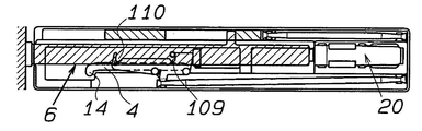
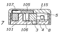
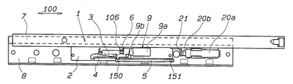
도 1은 구동부재가 문이 닫힐 때의 초기 위치에 있는 본 발명의 제1의 바람직한 구현예에 따른 장치의 평면도이다.
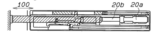
도 2는 구동핀이 제1 슬라이더의 후방 슬롯에서 분리된 도 1에 따른 장치를 도시한다.
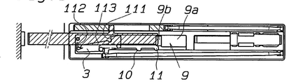
도 3은 구동핀이 문이 사용자가 잡을 수 있기에 적합한 양으로 열려진 위치에서 제1 슬라이더의 전방 슬롯의 측벽에 부착된 도 1의 장치를 도시한다.
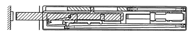
도 4는 사용자의 외부 동작을 통하여, 구동핀이 제1 슬라이더에서 분리되고 문이 구동부재에서 해제된 경우의 도 1의 장치를 도시한다.
도 5는 구동부재의 후퇴 중에, 구동핀이 제1 슬라이더의 후방 슬롯의 측벽에 대항하여 충격을 받는 순간의 도 1의 장치를 도시한다.
도 6은 문이 열릴 때, 초기 위치로 후퇴한 구동부재를 보여주는 도 1의 장치를 도시한다.
도 7은 7-7선을 따른 도 1의 장치의 단면도이다.
도 8은 가구 부재에 맞추어지고 자신의 커버에 쌓여 있는 도 1의 장치를 도시한다.
도 9는 도 1의 장치의 고정 가이드의 평면도이다.
도 10은 도 1의 장치의 고정 가이드의 커버 내부의 평면도이다.
도 11은 도 1의 장치의 구동부재의 평면도이다.
도 12는 도 1의 장치의 제2 슬라이더의 측면도이다.
도 13은 본 발명을 제공하는 제2의 바람직한 형태에 따른 장치가 있는 서랍용 가이드의 오른쪽 부분에 대한 평면도이다.
도 14는 도 13의 장치의 부분확대된 측면도이다.
도 15는 서랍이 닫힘 위치에 있는 경우에 대한 평면도이다.
도 16은 서랍이 가구 부재 내부로 더 후퇴하도록 하고 슬라이더를 제2 스프링의 동작에 반대하여 움직이도록 하는 가벼운 압력을 받은 후의 도 15에 따른 장치를 도시한다.
도 17은 서랍이 사용자에 의하여 잡을 수 있는 만큼 열린 슬라이더의 전방 슬롯의 측벽에 대항하여 구동핀이 부착된 도 13의 장치를 도시한다.
도 18은 사용자의 외부 동작을 통하여, 슬라이더의 전방 슬롯에 체결된 구동핀이 가이드 수단이 제1 이동수단에서 분리될 때까지 구동하는 도 13의 장치를 도시한다.
도 19는 슬라이더의 가이드 수단이 제2 이동수단에 체결되고 구동핀이 슬라이더에서 분리된 도 13의 장치를 도시한다.
도 20은 도 13의 장치를 참조하여, 구동핀이 슬라이더의 후방 슬롯의 측벽과 체결된 서랍의 닫히는 단계를 도시한다.
도 21은 탄성적 유연 정지부재가 기계적 정지부재로 대체된, 본 발명에 따른 장치의 하나의 가능한 변형을 도시한다.1 is a plan view of a device according to a first preferred embodiment of the invention in which the drive member is in an initial position when the door is closed.
2 shows the device according to FIG. 1 with the drive pin removed at the rear slot of the first slider.
3 shows the device of FIG. 1 with the drive pin attached to the side wall of the front slot of the first slider in a position where the door is opened in an amount suitable for the user to grab.
FIG. 4 shows the device of FIG. 1 when the drive pin is detached from the first slider and the door is released from the drive member, through an external action of the user.
FIG. 5 shows the device of FIG. 1 at the moment the drive pin is impacted against the side wall of the rear slot of the first slider during retraction of the drive member. FIG.
Figure 6 shows the device of Figure 1 showing the drive member retracted to its initial position when the door is opened.
7 is a cross-sectional view of the device of FIG. 1 along lines 7-7.
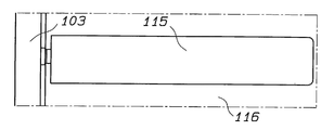
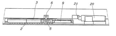
8 shows the device of FIG. 1 fitted to a piece of furniture and stacked on its cover.
9 is a plan view of the fixing guide of the apparatus of FIG. 1.
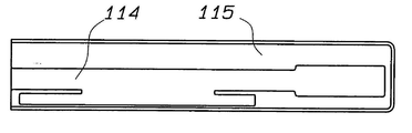
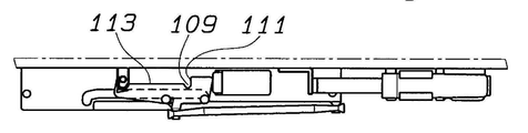
10 is a plan view inside the cover of the fixing guide of the device of FIG.
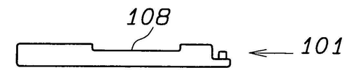
11 is a plan view of the drive member of the apparatus of FIG. 1.
12 is a side view of the second slider of the apparatus of FIG. 1.
Figure 13 is a plan view of the right side of a guide for a drawer with a device according to a second preferred form of the present invention.
FIG. 14 is an enlarged side view of the device of FIG. 13. FIG.
15 is a plan view of the case where the drawer is in the closed position.
FIG. 16 shows the device according to FIG. 15 after being subjected to light pressure to cause the drawer to retract further into the furniture member and to move the slider against the action of the second spring.
FIG. 17 illustrates the device of FIG. 13 with a drive pin attached against the side wall of the front slot of the slider that the drawer can hold by the user.
FIG. 18 shows the device of FIG. 13, through an external motion of the user, driving the drive pin fastened to the front slot of the slider until the guide means is disengaged from the first moving means.
FIG. 19 shows the device of FIG. 13 with the guide means of the slider fastened to the second moving means and the drive pins separated from the slider.
20 shows the closing of the drawer in which the drive pin is engaged with the side wall of the rear slot of the slider with reference to the device of FIG.
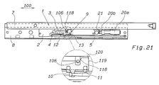
Figure 21 shows one possible variant of the device according to the invention in which the elastic flexible stop member is replaced by a mechanical stop member.
상세한 설명에서, 동일한 도면부호는 동일한 부재를 나타내기 위하여 사용되었다.In the detailed description, the same reference numerals are used to denote the same members.
도 1 내지 12에 도시된 본 발명의 제1의 바람직한 구현예을 참조한다.Reference is made to the first preferred embodiment of the invention shown in FIGS. 1 to 12.
본 발명에 따른 이동 가구 부재용 자동닫힘장치가 도시되어 있고, 모두 도면부호 1로 표시되어 있다.An automatic closing device for a mobile furniture member according to the invention is shown, all of which are indicated by
본 구현예에서 특정하여 설명하는 이동 가구 부재(103)는 가구 부재의 본체에 대하여 스윙(swing)하는 문이지만, 더 일반적으로는 서랍이나 이와 유사한 부재들 또한 가능할 수 있다.The moving
더 나아가, 상술한 바와 같이, 본 발명은 가정용 또는 이와 유사한 용도의 일반적 문 분야에도 또한 적용될 수 있다.Furthermore, as noted above, the present invention can also be applied to general door applications for home or similar use.
본 장치(1)는 바람직하게는 가구 부재의 고정부(116)에 조여진 고정 가이드(8)와 결합하고 제1 탄성 수단, 특히 제1 스프링(5)의 동작에 반대 및 관통하여 홈(4)의 후방 말단과 전방 말단 사이에서 미끄럼축의 방향(100)에서 역으로 움직이는 제1 슬라이더(3)를 위한 지지체(2)를 가진다.The
홈(4)은 미끄럼축의 방향(100)에서 직선적으로 연장된다.The
제1 슬라이더(3)는 고정 가이드(8)에서 후퇴된 위치 및 고정 가이드(8)에서 인출된 위치 사이에서 미끄럼축의 방향(100)에서 역으로 움직이는 구동부재(6) 상에 존재하는 제1 구동수단에 의하여 체결될 수 있다.The
후방 말단 영역에서, 홈(4)은 제1 슬라이더(3)의 특정의 가이드 수단과 체결되기에 적합한 미끄럼축에 횡방향(100)으로 있는 제1 슬라이더(3)의 제1 이동 수단을 포함한다.In the rear distal region, the
더 나아가, 전방 말단 영역에서, 홈(4)은 제1 슬라이더(3)의 가이드 수단과 체결되기에 적합한 미끄럼축에 횡방향(100)으로 있는 제1 슬라이더(3)의 제2 이동 수단을 포함한다.Furthermore, in the front end region, the
제1 이동수단은 중간 측공(10) 및 홈(4)의 후방커브(11)를 포함한다. 이와 달리, 제2 이동수단은 중간 측공(10) 및 후방 커브(11)가 위치하는 홈(4)의 동일한 부분에서 연장된 홈(4)의 전방 커브(4)를 포함한다.The first moving means includes a
이에 따라 가이드 수단은 전방 가이드 핀(12) 및 후방 가이드 핀(13)을 포함한다.The guide means thus comprise a
전방 가이드 핀(12) 및 해당 후방 가이드 핀(13)은 중간 측공(10) 및 홈(4)의 해당 후방 커브(11)에서 체결되기에 적합하고, 전방 가이드 핀(12)은 이와 다른 선택사항으로 홈(4)의 전방 커브(14)에서 체결되기에도 또한 적합하다.The
제1 슬라이더(3)는 구동핀(106)이 선택적으로 체결되는 후방 표면 슬롯(109) 및 전방 표면 슬롯(110)을 포함한다.The
후방 슬롯(109) 및 전방 슬롯(110)은 각각 구동핀(106)을 차단하기 위하여 전방 슬롯(109) 및 후방 슬롯(110) 사이에 분리면(113)에 대하여 돌출한 측벽(111 및 112)을 포함한다.The
특히, 분리면(113)은 편평하고 측벽(111 및 112)은 분리면(113)의 평면을 넘어 돌출한다.In particular, the separating
본 장치(1)는 또한 지지체(2)에 고정된 탄성적 유연 정지부재(9)를 구비하고, 제1 슬라이더(3)는 홈의 제1 이동 수단에서 가이드 수단과 체결되기 전에 직접 또는 간접적으로 지지체에 대항하여 기대어 있다.The
정지부재(9)는, 미끄럼축의 방향(100)으로 설정된 주축(main axis)을 가지고, 고정부재(9a) 및 이동부재(9b)를 포함하는데, 이들 사이에 스프링(도시되지 않음)이 중간에 배치되어 있고, 유리한 이점으로서 제1 스프링(5)보다 더 큰 탄성 강도를 가짐으로써, 제1 슬라이더(3)가 자유롭게 미끄러질 때, 이동부재(103)의 닫힘 위치에 해당하는 위치에서 이를 정지시킬 수 있다.The
본 장치(1)는 또한 이동부재(103) 및 구동부재(6) 사이에서 착탈식 결합을 위한 수단(104)을 포함한다.The
결합수단(104)은 알려진 유형, 예를 들면, 이동부재(103)의 내측 및 구동부재(6)의 전방 말단에 고정된 유형의 자석식 또는 기계식 연결수단을 포함한다.The coupling means 104 comprises a magnetic or mechanical connection means of known type, for example of a type fixed to the inside of the moving
자석식 연결의 경우에, 결함수단에 의하여 발생한 결합력은 사용자에 의하여 발생된 적정한 힘의 결과로서 이탈 가능하도록 보정되어야 한다. 기계적 유형 연결의 경우에, 결합수단은 구동부재(6)의 인출 위치에서 부재들의 분리가 가능해야 한다.In the case of a magnetic connection, the engagement force generated by the faulty means must be corrected to be detachable as a result of the proper force generated by the user. In the case of a mechanical type connection, the coupling means must be capable of separating the members at the withdrawal position of the
본 장치(1)가 이동부재(103)가 닫히는 방향에서 푸시를 발하는 경첩을 구비한 가구 부재에 적용되는, 제1의 바람직한 구현예에서, 제2 슬라이더(101) 또한 제공되어, 고정 가이드(8)에 의하여 수행되고 제2 탄성수단, 특히 제2 스프링(102)의 동작에 대항 및 관통하여 미끄럼축의 방향(100)에서 역으로 움직인다.In a first preferred embodiment, in which the
제2 슬라이더(101)는 구동부재(6) 상에 존재하는 제2 구동수단(107)과 체결될 수 있다. 이 경우에 결합수단의 결합력은 제1 및 제2 탄성부재, 및 특히 제1 스프링(5) 및 제2 스프링(102)에 의하여 구동부재(6) 상에 간접적으로 가해진 후퇴 위치를 향하는 탄성 회복력의 합보다 더 커야한다. The
구동부재(6)는 막대형 본체(105)를 포함하고 고정 가이드(8)의 커버(115)에 제공된 가이드부재(114) 내에 미끄러지도록 제공된다.The
막대형 본체(105)의 축은 미끄럼축의 방향(100)으로 연장된다.The axis of the rod-shaped
구동부재(6)의 제1 구동수단은 막대형 본체(105)에 횡방향으로 연장된 구동핀(106)을 포함하고 제1 슬라이더(3)와 체결되기에 적합하다.The first drive means of the
구동부재(6)의 제2 구동수단은 막대형 본체(105)로부터 평행하게 연장된 탭(107)을 포함하고 제2 슬라이더(101)에 제공된 가이드 슬롯(108) 내에서 미끄러지도록 제한된다.The second drive means of the
마지막으로, 본 장치(1)는 구동부재(6)의 뒤에 있는 고정 가이드(8) 내에 지지된 이젝터(20)를 포함한다.Finally, the
이젝터(20)는, 이동 스핀들(20a)을 구비한 고정부재(20a)를 포함하고, 경첩과 일체로 된 장치와 같은, 독립 닫힘 장치에 의하여 가해진 힘보다 더 큰 힘으로 초기에 이동부재(103)가 열리는 움직임을 만드는 막대형 본체(105)의 후방 바닥에 대항하여 동작하기에 적합하다.The
그러나, 이젝터(20)에 의하여 가해진 방출력(ejection force)은 제1 스프링(5)의 탄성력보다 작다.However, the ejection force exerted by the
유리한 이점으로서 이젝터(20)는 알려진 방법으로 가해진 추력(pushing force)을 조절하기 위한 장치를 구비한다.As an advantageous advantage, the
이젝터(20)는 또한 미끄럼축의 방향(100)으로 설정된 주축을 가진다.The
본 발명에 따른 장치의 동작은 상세한 설명과 예시로부터 명백하고, 특히 이하에서 실질적으로 명백하게 설명된다.The operation of the device according to the invention is evident from the description and the examples, and in particular is made substantially clear below.
도 1은 이동부재(103)가 닫히는 때의 본 장치(1)의 상태를 나타낸다.1 shows the state of the
이동부재(103)가 닫히고 구동부재(6)와 결합하는 제1 단계에서, 구동 핀(106)은 탄성적으로 유연한 정지부재(9)에 대항하여 있는 제1 유휴 위치에 있는 제1 슬라이더(3)의 후방 슬롯(109)에서 체결되고, 스프링은 눌리지 않고, 제1 슬라이더(3)를 제위치에 유지하기 위하여 예압(preload)된다. 구동 부재(6)의 후방 말단은, 이젝터(20)의 힘이 제1 스프링(5)의 힘보다 작을 때와 같이, 후퇴 위치에 스핀들(20b)을 두는 이젝터(20)의 머리에 대항하여 있다.In a first step, in which the moving
구동 부재(6) 회복의 후속하는 제2 단계에서, 도 2에 도시된 바와 같이, 제1 슬라이더(3)는 이동부재(103)의 외부 압축력(예를 들면, 사용자에 의하여 발생한 힘)에 의하여 제2 위치로 후퇴 이동하도록 만들어진다.In the subsequent second stage of recovery of the
제1 슬라이더(3)의 제2 위치에서, 전방 가이드 핀(12)과 해당 후방 가이드 핀(13)은 중간 측면 공(10) 및 홈(4)의 해당 후방 커브(11)에 체결된다. 슬라이딩 축에 횡방향(100)으로 있는 제1 슬라이더(3)의 움직임은 구동 핀(106)을 후방 슬롯(109)에서 분리되도록 한다.In the second position of the
후속하는 제3 단계에서, 도 3에 도시된 바와 같이, 구동 핀(103)은, 이젝터(20)에 의하여 가해진 누름의 결과로 후방 슬롯(109) 및 구동 부재(6)로부터 해제되고 스프링(5)에 의하여 이제 일시적으로 더 이상 반대되지 않는, 또는 사용자에 의하여 자연적으로, 이동부재(103)가 구동핀(106)이 제1 슬라이더(3)의 전방 슬롯(110)의 돌출한 측벽(112)에 의하여 차단될 때에 종료하는 초기 열림 동작을 수행하도록 인출된다.In a subsequent third step, as shown in FIG. 3, the
처음 세 개의 단계에서, 탭(107)은 가이드 슬롯(108)에서 자유롭게 미끄러진다.In the first three stages, the
후속하는 제4 단계에서, 도 4에 도시된 바와 같이, 이동부재(103)에 가해진 외부 견인력(예를 들면, 사용자에 의하여 발생한 힘)의 결과로, 제1 슬라이더(3)의 전방 슬롯(110)의 측벽(112)에 의하여 차단된, 구동핀(106)은 처음으로 제1 슬라이더(3)를 구동하여 전방 가이드 핀(12) 및 해당 후방 가이드 핀(13)이 중간 측공(10) 및 홈(4)의 해당 후방커브(11)로부터 분리되도록 한다. 미끄럼축에 횡방향(100)으로 있는 제1 슬라이더(3)의 움직임은 이때 구동핀(106)이 전방 슬롯(110)에서 체결되도록 한다. 제4 단계 동안에, 가이드 슬롯(108)의 전방 말단과 접하고 난 후에, 탭(107)은 제2 슬라이더(101)의 전방 말단이 고정 가이드(8)의 전방 벽에 의하여 차단되는 위치에서 제2 슬라이더(101)를 그 이동의 말단까지 구동하기 시작하고 결과적으로 구동부재(6)의 더 이상의 진행이 차단된다. 제2 슬라이더(101)가 이동의 말단에 이르기 전에, 전방 가이드 핀(12)이 홈(4)의 전방커브(14)와 체결되어 제1 슬라이더(3)가 이동방향(100)에 대하여 횡으로 움직이도록 하고, 이 결과로 구동핀(106)은 전방 슬롯(110)으로부터 분리된다. 결합수단으로 확보된 결합력은 제1 스프링(5)과 제2 스프링(102)에 의하여 발생한 회복력의 합보다 더 크고, 따라서 구동부재(6)가 전방으로 구동될 수 있다. 구동부재(6)가 인출 과정에서 이동의 말단에 이를 때, 자기적 연결(magnetic connection)의 경우에, 이동부재(103) 상의 견인력은 결합수단에 의하여 확보된 결합력에 비하여 우세하게 되고, 또한, 기계적 연결의 경우에, 결합수단이 결합에서 해제되고, 이동부재(103)가 구동부재(6)로부터 해제되어 완전히 열린 위치에 이를 수 있다.In a subsequent fourth step, as shown in FIG. 4, the
후속하는 제5 단계에서, 도 5에 도시된 바와 같이, 제2 슬라이더(101)는, 스프링(102)를 통하여, 구동부재(6)를 고정 가이드(8)의 내부를 향하여 후퇴시킨다. 이 단계 중에 구동핀(106)은, 후방 슬롯(109)의 측벽(111)에 의하여 차단되고, 초기에 제1 슬라이더(3)가 미끄러지는 방향(100)에 대하여 횡으로 이동하도록 하고 전방 가이드 핀(12)을 전방 커브(14)로부터 분리되도록 한다. 결과적으로, 제1 슬라이더(3) 또한, 스프링(5)을 통하여, 제1 단계에서 취해진 위치로 회복될 수 있다(도 6).In a subsequent fifth step, as shown in FIG. 5, the
스윙 가구부재(swining furniture part)가 열리는 방향에서 눌림을 갖는 탄성 시스템을 구비한 경첩을 갖는 가구부재의 경우에, 다시 닫힐 때에 스윙부재를 재-결합하기 위하여 인출된 위치에 구동부재(6)를 유지하는 것이 필요하다. 따라서 이러한 유형의 경첩은 제2 슬라이더와 제2 탄성수단을 불필요한 것으로 만들고, 구동부재(6)가 결합할 때 슬라이더(3)를 뒤로 후퇴시키는 스프링(5)에 의하여 발생한 스윙 부재의 닫힘 움직임을 감속하기 위한 감속기가 이젝터를 대신하여 선택사항으로 제공되도록 한다. 따라서 본 장치는 문 또는 서랍의 단순하고 기능적인 개폐를 가능하게 하여 사용자가 잡기 용이하게 하고 가이드 된 닫힘을 제공한다.In the case of a hinged furniture member with an elastic system having a depression in the direction in which the swing furniture part is opened, the
도 13-20에 도시된 본 발명의 제2의 바람직한 구현예를 참조한다.Reference is made to a second preferred embodiment of the invention shown in FIGS. 13-20.
본 발명에 따른, 이동 가구 부재용 자동-닫힘장치가 도시되어 있고, 이들 모두는 도면부호 1로 표시되어 있다.In accordance with the invention, an auto-closing device for a mobile furniture member is shown, all of which are indicated with
이 바람직한 구현예가 특정적으로 언급하는 이동 가구 부재(103)는 서랍이지만, 더 일반적으로는 가구부재의 본체 또는 이에 유사한 부재들에 대하여 스윙하는 문일 것이다. 더 나아가, 언급한 바와 같이 본 발명은 가정용 또는 이와 유사한 용도의 일반적 문 분야에도 또한 응용될 수 있다. 본 장치(1)는, 고정 가이드(8)와 연관되어, 미끄럼축(100)을 따라 제1 탄성수단, 특히 한쪽 말단에서는 슬라이더(3)의 연장부에 만들어진 연결(150)과 결합하고 다른 한쪽 말단에서는 지지체(2)의 연장부에 만들어진 연결(151)과 결합한 제1 스프링(5)에 대항 또는 관통하여(in opposition to and through) 역으로 움직이는 슬라이더(3)용 지지체(2)를 포함한다.The
슬라이더(3)는 서랍의 인출가능 가이드(7)와 일체로 된 미끄럼축의 방향(100)에서 역으로 움직이는 구동부재(6) 상에 존재하는 구동수단에 고정되어 여기에 체결될 수 있다.The
그러나, 지지체(2)를 인출가능 가이드(7)와 연결하고 구동부재(6)를 고정 가이드(8)와 연결하는 것 또한 가능할 것이다. 지지체(2)는, 구동수단으로부터 이탈될 수 있도록, 슬라이더(3)의 특정의 가이드 수단과 체결되기에 적합한 슬라이더(3)의 움직임을 위한 제1 수단을 포함한다.However, it will also be possible to connect the
탄성적 유연 정지부재(9) 또한 존재하고, 슬라이더(3)는, 제1 움직임 수단에 있는 가이드 수단과 체결되기 전에, 직접 또는 간접으로 이 탄성적 유연 정지부재(9)에 대항하여 유지된다.An elastic
정지부재(9)는, 미끄럼축의 방향(100)으로 설정된 주축(main axis)을 갖고, 스프링(도시되지 않음)이 중간에 배치된 고정부재(9a) 및 이동부재재(9b)를 포함하고, 이로운 점으로서 제1 스프링(5)보다 더 큰 탄성 강도를 가지고 따라서, 제2 슬라이더(3)가 자유롭게 미끄러질 때, 이동부재(103)의 닫힌 위치에 해당하는 위치에서 이를 멈추게 할 수 있다.The
결합수단은 미끄럼축에 횡방향(100)으로 연장되고 슬라이더(3)와 체결되기에 적합한 구동핀(106)을 포함한다.The coupling means comprises a
지지체(2)는 후방 말단 영역에서 슬라이더(3)의 움직임을 위한 제1 수단 및 전방 말단 영역에서 슬라이더(3)의 가이드 수단과 체결되기에 적합한 미끄럼축에 횡방향(100)으로 슬라이더(3)의 움직임을 위한 제2 수단을 포함하는 홈(4)을 가진다.The
홈은 미끄럼축의 방향(100)에서 직선적으로 연장한다.The groove extends linearly in the direction of the sliding
제1 움직임 수단은 중간 측공(10) 및 홈(4)의 후방 커브(11)를 포함한다. 제2 움직임 수단은 대신에 중간 측공(10)과 후방 커브(11)가 위치하는 홈(4)의 같은 부분에서 연장한 홈(4)의 전방 커브(14)를 포함한다.The first means of movement comprises a
가이드 수단은 전방 가이드 핀(12)과 후방 가이드 핀(13)을 포함한다.The guide means comprise a
전방 가이드 핀(12)과 후방 가이드 핀(13)은 각각 중간 측공(10)과 홈(4)의 후방 커브(11) 각각에서 체결되기에 적합하고, 전방 가이드 핀(12)은 이와 다른 선택으로 홈(4)의 전방 커브(14)에서 또한 체결되기에 적합하다.The front guide pins 12 and the rear guide pins 13 are suitable for fastening at the
제1 슬라이더(3)는 구동핀(106)이 선택적으로 체결되는 후방 표면 슬롯(109)과 전방 표면 슬롯(110)을 포함한다.The
후방 슬롯(109)과 전방 슬롯(110)은 각각 구동핀(106)을 차단하기 위하여 전방 슬롯(109)과 후방 슬롯(110) 사이에 있는 분리면(113)에 대하여 돌출한 측벽(111 및 112)을 가진다.The
특히, 분리면(113)은 편평하고 측벽(111 및 112)은 분리면(113)의 평면을 넘어 돌출한다.In particular, the separating
초기에 서랍을 여는데 필요한 움직임을 제공하기에 적합한 이젝터(20)가 본 장치와 연결될 수 있다.An
이젝터(20)는 인출가능한 가이드(7)와 일체로 된 정지부재(21)와 상호작용하기에 적합하지만, 이 힘은 제1 스프링(5)에 의하여 발생한 힘보다 작다.The
이젝터(20)는, 가동 스핀들(20b)을 포함하는 고정부재(20a)를 포함하고, 발생한 답력(pushing force)을 알려지 방식으로 조절하기 위한 장치를 구비하고, 또한 미끄럼축의 방향(100)으로 조절된 주축을 가진다.The
구성적 변형(도시되지 않음)에서, 중력을 통하여 미끄러질 수 있는, 서랍의 고정 및/또는 미끄럼 가이드의 적절한 경사(도시되지 않음)가 이젝터를 대신할 수 있다.In a constructional variant (not shown), an appropriate incline (not shown) of the drawer's fixation and / or sliding guide, which can slide through gravity, may replace the ejector.
더 나아간 구성적 변형에서 반발력을 만들도록 방향이 설정되어, 서랍이 미끄러질 수 있도록 하고, 기타의 경우에서와 같이, 사용자에 의하여 용이하게 잡을 수 있도록 하는 자석(도시되지 않음)이 이젝터를 대신할 수 있다.The magnets (not shown) can be replaced by ejectors, which are oriented to create a repulsive force in further constituent deformations, allowing the drawer to slide and, as in other cases, be easily gripped by the user. have.
본 발명에 따른 장치의 동작은 상세한 설명 및 예시로부터 명백하고, 특히 아래에 설명하는 바에 의하여 실질적으로 명백한 것이다.The operation of the device according to the invention is apparent from the description and examples, and in particular from the description below.
도 15는 서랍이 닫힐 때의 본 장치(1)의 상태를 나타낸다. 구동핀(106)은 탄성적 유연 정지부재(9)에 대항하여 기대어 있는 제1 유휴 위치에 배치된 슬라이더(3)의 후방 슬롯(109)에서 체결되고, 이의 스프링은 압축되지 않지만, 슬라이더(3)를 제위치에 배치하기 위하여 예압된다. 정지부재(21)는, 이젝터(20)의 힘이 제1 스프링(5)의 힘보다 작은 경우와 같이, 후퇴 위치 내에 스핀들(20b)을 갖는 이젝터(20)의 머리에 대항하여 기대어 있다. 15 shows the state of the
후속하는 단계에서, 도 16에 도시된 바와 같이, 슬라이더(3)는 서랍에 응용된 외부 압축력(예를 들면, 사용자에 의하여 발생한 힘)에 의하여 뒤로 움직이도록 만들어진다. 이러한 슬라이더(3)의 위치에서 전방 가이드 핀(12)과 후방 가이드 핀(13) 각각은 중간 측공(10)과 홈(4)의 후방 커브(11) 각각에 체결된다. 미끄럼 축에 횡방향(100)으로 있는 슬라이더(3)의 움직임은 구동핀(106)을 후방 슬롯(109)에서 분리되도록 한다.In a subsequent step, as shown in FIG. 16, the
후속하는 단계에서, 도 17에 도시된 바와 같이, 구동핀(103)은 후방 슬롯(109)으로부터 이탈되고, 이젝터에 의하여 발생하고 현재 일시적으로 스프링(5)의 의하여 또는 사용자에 의하여 자연적으로 더 이상 반발하지 않는 누름의 결과로서, 서랍이 구동핀(106)이 슬라이더(3)의 전방 슬롯(110)의 돌출한 측벽(112)에 의하여 차단될 때에 종결하는 초기의 열림 움직임을 수행하도록 움직인다.In a subsequent step, as shown in FIG. 17, the
후속하는 단계에서, 도 18에 도시된 바와 같이, 서랍에 작용하는 외부 견인력(예를 들면, 사용자에 의하여 발생한 힘)의 결과로서, 구동핀(106)은, 슬라이더(3)의 전방 슬롯(110)의 측벽(112)에 의하여 차단되고, 우선 슬라이더(3)를 구동하여 전방 가이드 핀(12)과 후방 가이드 핀(13) 각각을 중간 측공(10)과 홈(4)의 후방 커브(11) 각각으로부터 분리되도록 한다. 다음에 슬라이더(3)의 미끄럼축에 횡방향(100)으로의 움직임은 구동핀(106)을 전방 슬롯(110)에 체결되도록 한다.In a subsequent step, as shown in FIG. 18, as a result of the external traction force (eg, a force generated by the user) acting on the drawer, the
후속하는 단계 중에, 도 19에 도시된 바와 같이, 전방 가이드 핀(12)은 홈(4)의 전방 커브(14)와 체결되어 슬라이더(3)를 움직임 방향(100)에 대하여 횡으로 움직이게 하고, 이 결과로 구동핀(106)은 전방 슬롯(110)에서 분리되고 서랍의 완전한 열림 위치로 자유롭게 진행한다.During the subsequent step, as shown in FIG. 19, the
후속하는 닫힘 단계에서, 도 20에 도시된 바와 같이, 서랍은 사용자에 의하여 밀어져 닫힌다. 이 단계 중에 구동핀(106)은, 후방 슬롯(109)의 측벽(111)에 의하여 차단되고, 초기에 슬라이더(3)를 미끄럼 방향(100)으로 횡으로 움직이도록 하고 전방 가이드 핀(12)을 전방 커브(14)로부터 분리되도록 한다. 결과적으로, 슬라이더(3)는, 스프링(5)을 통하여 제1 단계에서 취해진 위치로 회복될 수 있다(도 15).In the subsequent closing step, as shown in FIG. 20, the drawer is pushed by the user to close it. During this step, the drive pins 106 are blocked by the
전체 시스템을 더 소형으로 만들어야 할 필요가 있는 경우에, 이젝터는 탄성적으로 유연한 부재의 뒤에 있는 지지체(2) 상에 내장될 수 있다.If it is necessary to make the whole system smaller, the ejector can be embedded on the
더 나아가, 이미 설명한 바와 같이, 자석이나 기타 서랍을 움직이기에 적합한 시스템들보다, 경사 가이드가 이젝터를 대신할 수 있다.Furthermore, as already described, the inclined guide may replace the ejector, rather than systems suitable for moving magnets or other drawers.
지금 특히, 도 21을 참조하면, 탄성적 유연한 정지부재(9)는 슬라이더(3)의 방향으로 횡으로 배열된 지지체(2)의 스텝(120)에 의하여 형성된 기계적 정지부재로 대신한다. 슬라이더(3)는 후방 벽(119)과 함께 스텝(120)에 대항하여 기대어 있다. 외부로부터 인가된 힘을 수단으로, 이동 가구 부재 상에서, 인출가능한 가이드(7)와 일체로 된 핀(106)이 슬라이더(3)의 경사진 표면(118)에 대항하여 눌리고, 스텝(120)을 따라서 홈(4)의 적절합 측 슬롯(10, 11) 내부에서 평행한 움직임을 초래하고 따라서, 핀(106)이 이탈되고 인출가능한 가이드(7)가 이젝터(20a, 20b)에 의하여 열리도록 눌려질 수 있다.Referring now particularly to FIG. 21, the elastically
실제의 적용에서, 본 발명에 따른 장치가 서랍의 개폐를 단순하고 기능적으로 하도록 하여 사용자에 의하여 용이하게 잡을 수 있고 가이드 되어 닫히는 점에서 특히 유리한 이점이 있다. In practical application, there is a particular advantage in that the device according to the invention makes opening and closing of the drawer simple and functional so that it can be easily held by the user and guided to close.
따라서 착상된 본 발명은 수많은 수정과 변형이 이루어질 수 있고, 이들 모두는 본 발명의 개념의 범위 내에 포함되고; 더 나아가, 모든 세부적 사항들은 기술적으로 등가의 부재들로 대신할 수 있다.Accordingly, the presently conceived invention may be subject to numerous modifications and variations, all of which fall within the scope of the inventive concept; Furthermore, all details can be substituted by technically equivalent members.
실제의 적용에서, 사용된 재료들과 크기들은 필요한 요건조건 및 본 기술분야의 상태에 따라 임의의 것을 선택할 수 있다.
In practical application, the materials and sizes used may be selected according to the requirements and the state of the art.
Claims (22)
상기 제1 슬라이더(3)는 상기 미끄럼 축(100)의 방향에서 역으로 미끄러지는 구동 부재(6)에 존재하는 제1 구동수단과 체결되고,
상기 지지체(2)는, 상기 구동 수단으로부터 해제될 수 있도록 하는, 상기 제1 슬라이더(3)의 제1 이동수단을 포함하고,
상기 제1 슬라이더(3)가 상기 제1 이동수단에서 상기 가이드 수단과 체결되기 전에 직접 또는 간접적으로 대항하도록 기대어 있는 기계적 또는 탄성적 유연 정지부재(9, 120)를 구비하는 것을 특징으로 하는 특히 이동 가구 부재(103)의 자동닫힘장치(1).
The first slider 3 comprises a fixing guide 8 having a support 2 which can slide in opposition to and through the opposing operation of the first elastic member along the sliding axis 100. and,
The first slider 3 is engaged with the first drive means present in the drive member 6 sliding backwards in the direction of the sliding axis 100,
The support 2 comprises a first moving means of the first slider 3, which can be released from the driving means,
In particular the movement is characterized in that the first slider 3 has a mechanical or elastic flexible stop member 9, 120 which is leaning against it directly or indirectly before engaging it with the guide means in the first movement means. Automatic closing device (1) of the furniture member (103).
2. Automatic closing device (1) according to claim 1, characterized in that the drive means comprise drive pins (106) suitable for engagement with the first slider (3).
The area of the rear end according to one or more of the preceding claims, wherein the support (2) is transverse to (100) the sliding axis suitable for engaging with the guide means of the first slider (3). Having a groove 4 comprising the first means for movement of the first slider 3 and a second means for movement of the first slider 3 in the region of the front end. Characterized by an automatic closing device (1).
4. Automatic closing device (1) according to claim 3, characterized in that the first means of movement comprises an intermediate side cavity (10) and a rear curve (11) of the groove (4).
5. The groove according to claim 3 or 4, wherein the second moving means is arranged in the same portion of the groove (4) in which the intermediate side cavity (10) and the rear curve (11) are located. Automatic closing device (1), characterized in that it comprises a front curve (14).
According to one or more of the preceding claims, the guide means comprise a front guide pin (12) and a rear guide pin (13), wherein the front guide pin (12) and the rear guide pin (13) are at the intermediate side. It is adapted to be fastened at the rear curve 11 of the cavity 10 and the groove 4, and the front guide pin 12 is also optionally adapted to be fastened at the front curve 14. Automatic closing device, characterized in that (1).
The automatic closing device according to any one of the preceding claims, wherein the first slider (3) comprises a rear slot (109) and a front slot (110) to which the drive pin (106) is selectively fastened. (One).
The front slot 110 and the rear slot 109 of claim 7, wherein the front slot 110 and the rear slot 109 protrude with respect to the surface 113 to block the driving pin 106. Automatic closing device (1), characterized in that it comprises a respective side wall (112, 111) for separating 109.
The automatic closing device (1) according to one or more of the preceding claims, characterized in that the drive member (6) is supported to slide on the guide member (114) introduced in the cover (115) of the fixed guide (8). ).
Automatic closing device (1) according to one or more of the preceding claims, characterized in that it comprises a removable engagement means (104) between the moving member (103) and the drive member (6).
The second slider according to one or more of the preceding claims, carried by the fixing guide (8) and sliding back in the direction of the sliding axis (100) against and through the operation of the second elastic member (102). Automatic closing device (1), characterized in that it comprises a (101).
12. The removable coupling means (104) according to claim 10 or 11, wherein the removable engagement means (104) is greater than the sum of the elastic recovery forces applied indirectly to the drive member by the first elastic means (5) and the second elastic means (102). Automatic closing device, characterized in that having a coupling force (1).
12. The device of claim 11, wherein the second drive means includes a tab (107) extending laterally from the drive member (6) and slides in a guide slot (108) introduced into the second slider (101). Automatic closing device (1), characterized in that limited.
The fixing guide 8 according to one or more of the preceding claims, behind the drive member 6, supports an ejector 20 suitable for making an initial opening movement of the movable member 103. Characterized by an automatic closing device (1).
Automatic closing device (1) according to one or more of the preceding claims, characterized in that the ejector (20) has an ejection force less than the elastic force of the first elastic means (5).
The drive guide (6) according to one or more of the preceding claims, wherein the fixed guide (2) is located behind the drive member (6) to slow down the closing of the movable member (103). Auto closing device (1), characterized in that it supports a reducer suitable for operation against said rear base.
Automatic closing device (1) according to one or more of the preceding claims, characterized in that the drive member (6) can slide back in the direction of the sliding axis (100) in combination with the extractable guide (7). .
The first elastic flexible stop member (9) according to one or more of the preceding claims, wherein the first elastic means (5) is on the slider (3) in contact with the first elastic flexible stop member (9). Automatic closing device, characterized in that to give an elastic force less than the elastic force generated by the).
The mechanical stop member according to one or more of the preceding claims, wherein the mechanical stop member is formed by a step (120) of the support (2) arranged transverse to the direction of the first slider (3), and the rear wall (119) Automatically closing device (1), characterized in that leaning against the step (120) with.
The inclined surface 118 according to claim 1, wherein the first slider 3 is adapted to be pressed against the drive pin 106 to move the first slider 3 laterally along the step 120. Automatic closing device, characterized in that it comprises a (1).
A furniture member comprising a hinge (1) according to one or more of the preceding claims and comprising a hinge with a device for pressing the movable furniture part in the closing direction.
Applications Claiming Priority (4)
| Application Number | Priority Date | Filing Date | Title |
|---|---|---|---|
| ITMI2008A001812A IT1392328B1 (en) | 2008-10-13 | 2008-10-13 | SELF-WELDING DEVICE FOR A MOVABLE PART OF A FURNITURE |
| ITMI2008A001812 | 2008-10-13 | ||
| ITMI2008A001849A IT1392653B1 (en) | 2008-10-17 | 2008-10-17 | AUTO DEVICE CLOSING A MOVABLE PART OF A MOBILE |
| ITMI2008A001849 | 2008-10-17 |
Publications (1)
| Publication Number | Publication Date |
|---|---|
| KR20110083625A true KR20110083625A (en) | 2011-07-20 |
Family
ID=41334539
Family Applications (1)
| Application Number | Title | Priority Date | Filing Date |
|---|---|---|---|
| KR1020117008380A KR20110083625A (en) | 2008-10-13 | 2009-09-28 | Self-closing and opening device particularly for a movable furniture part |
Country Status (12)
| Country | Link |
|---|---|
| US (1) | US8668288B2 (en) |
| EP (1) | EP2315898B1 (en) |
| JP (1) | JP5624547B2 (en) |
| KR (1) | KR20110083625A (en) |
| CN (1) | CN102203367B (en) |
| BR (1) | BRPI0914011A2 (en) |
| ES (1) | ES2397814T3 (en) |
| HK (1) | HK1158721A1 (en) |
| PL (1) | PL2315898T3 (en) |
| SI (1) | SI2315898T1 (en) |
| TW (1) | TWI437967B (en) |
| WO (1) | WO2010043306A1 (en) |
Families Citing this family (25)
| Publication number | Priority date | Publication date | Assignee | Title |
|---|---|---|---|---|
| IT1392907B1 (en) * | 2008-09-12 | 2012-04-02 | Salice Arturo Spa | SELF-CLOSING DEVICE FOR A DRAWER OR A MOVABLE PART OF A FURNITURE |
| DE102008061728A1 (en) * | 2008-12-12 | 2010-06-17 | Dorma Gmbh + Co. Kg | sliding door |
| IT1392184B1 (en) * | 2008-12-12 | 2012-02-22 | Salice Arturo Spa | OPENING AND CLOSING DEVICE FOR A MOVABLE PART OF A FURNITURE |
| JP5433466B2 (en) * | 2010-03-17 | 2014-03-05 | 株式会社ニフコ | Sliding assist device |
| JP2011196015A (en) * | 2010-03-17 | 2011-10-06 | Nifco Inc | Slide assist device |
| AT509934B1 (en) | 2010-05-20 | 2016-01-15 | Blum Gmbh Julius | DRIVE DEVICE FOR MOVING A MOVABLE FURNITURE PART |
| DE202010013193U1 (en) * | 2010-12-22 | 2012-03-26 | Paul Hettich Gmbh & Co. Kg | Opening and closing device for movable furniture parts and ejection device |
| DE102011122266A1 (en) * | 2011-12-23 | 2013-06-27 | Grass Gmbh | Device for influencing the movement of a furniture part, guide unit for moving a furniture part and furniture |
| AT511938B1 (en) * | 2012-01-18 | 2013-04-15 | Blum Gmbh Julius | DRIVE DEVICE FOR A MOVABLE FURNITURE PART |
| AT512509B1 (en) * | 2012-07-10 | 2013-09-15 | Blum Gmbh Julius | Ejecting device for a movable furniture part |
| ITMI20121718A1 (en) * | 2012-10-12 | 2014-04-13 | Salice Arturo Spa | MOBILE WITH AT LEAST ONE DRAWER OR LIKE |
| ES2474290B1 (en) * | 2013-01-08 | 2015-01-02 | Industrias Auxiliares, S.A. (Indaux) | SELF-CLOSURE DEVICE FOR SLIDING MOBILE PARTS |
| AT514143A1 (en) * | 2013-04-12 | 2014-10-15 | Blum Gmbh Julius | Drive device for a movable furniture part |
| DE102013103989A1 (en) * | 2013-04-19 | 2014-11-06 | Hettich-Heinze Gmbh & Co. Kg | guiding device |
| TWI538638B (en) | 2015-11-12 | 2016-06-21 | 川湖科技股份有限公司 | Drive mechanism and method for furniture parts |
| TWI536933B (en) | 2015-11-12 | 2016-06-11 | 川湖科技股份有限公司 | Slide rail assembly |
| TWI532452B (en) | 2015-11-12 | 2016-05-11 | 川湖科技股份有限公司 | Drive mechanism |
| TWI572304B (en) | 2016-03-31 | 2017-03-01 | 川湖科技股份有限公司 | Drive mechanism and method for furniture parts |
| CN107296407B (en) * | 2016-04-13 | 2019-03-15 | 川湖科技股份有限公司 | Furniture assembly and its driving mechanism, method |
| DE102016120593A1 (en) * | 2016-10-27 | 2018-05-03 | Hettich-Oni Gmbh & Co. Kg | Opening and closing system with an ejection device for a furniture and operating method for an opening and closing system |
| CN106361025B (en) * | 2016-11-11 | 2018-12-28 | 伍志勇 | A kind of furniture ejector structure |
| KR102470209B1 (en) * | 2018-04-27 | 2022-11-22 | 엘지전자 주식회사 | Drawer Guide and Laundry Treatment Apparatus having the same |
| WO2019238556A1 (en) * | 2018-06-13 | 2019-12-19 | Wolfgang Held | Device for opening and closing supported covers |
| IT201800011081A1 (en) * | 2018-12-13 | 2020-06-13 | Car S R L | OPENING DEVICE FOR A DOOR OR DRAWER AND CABINET INCLUDING THIS DEVICE |
| US10677512B1 (en) * | 2019-01-31 | 2020-06-09 | Whirlpool Corporation | Appliance push-to-open system and method of installing the push-to-open system |
Family Cites Families (20)
| Publication number | Priority date | Publication date | Assignee | Title |
|---|---|---|---|---|
| US3854785A (en) * | 1972-09-16 | 1974-12-17 | Krause Kg Robert | Actuating device |
| AT401717B (en) * | 1993-06-23 | 1996-11-25 | Blum Gmbh Julius | LOCKING DEVICE FOR DRAWERS |
| JP2550377Y2 (en) * | 1993-09-14 | 1997-10-08 | 磯川産業株式会社 | Magnet bush latch |
| IT250443Y1 (en) * | 2000-09-19 | 2003-09-10 | Salice Arturo Spa | DEVICE FOR THE DECELERATED CLOSURE OF SLIDING FURNITURE PARTS |
| JP3996584B2 (en) * | 2003-03-31 | 2007-10-24 | Thk株式会社 | Pull-in device, drawer device and sliding door device |
| MY140924A (en) * | 2003-05-22 | 2010-02-12 | Harn Marketing Sdn Bhd | A drawer stabilizing arrangement for double walled drawer |
| DE20311795U1 (en) * | 2003-07-31 | 2004-11-18 | Alfit Ag | Drawer pull-out guide with automatic retraction with integrated damping |
| ITMC20030144A1 (en) * | 2003-12-05 | 2005-06-06 | Compagnucci Spa Ora Compagnucci Ho Lding Spa | DEVICE FOR AUTOMATIC AND SUSPENSION CLOSING OF DRAWERS AND REMOVABLE FACILITIES FOR FURNITURE. |
| AT503066B1 (en) | 2004-12-03 | 2008-01-15 | Blum Gmbh Julius | DRIVE DEVICE FOR A MOVABLY STORED FURNITURE |
| DE202005009860U1 (en) * | 2004-12-17 | 2006-04-20 | Alfit Ag | Closing and opening device for drawers |
| AT502939A1 (en) * | 2005-04-28 | 2007-06-15 | Blum Gmbh Julius | FURNITURE |
| AT501778B1 (en) * | 2005-04-28 | 2009-11-15 | Blum Gmbh Julius | EJECTION DEVICE FOR A MOVABLE FURNITURE PART |
| EP1785063B1 (en) * | 2005-11-10 | 2012-03-14 | Grass GmbH | Device for opening and closing a movable furniture part and said furniture part |
| JP4806609B2 (en) * | 2005-11-21 | 2011-11-02 | トックベアリング株式会社 | Retraction unit |
| DE102006058639B4 (en) * | 2006-12-11 | 2008-08-14 | Zimmer, Günther | Combined deceleration and acceleration device |
| CN201182372Y (en) * | 2008-03-13 | 2009-01-21 | 佛山市顺德区泰明金属制品厂有限公司 | Drawer sliding rail switching-off devcie |
| DE102008021458A1 (en) * | 2008-04-29 | 2010-01-07 | Zimmer, Günther | Acceleration device with two energy storage devices |
| IT1392907B1 (en) * | 2008-09-12 | 2012-04-02 | Salice Arturo Spa | SELF-CLOSING DEVICE FOR A DRAWER OR A MOVABLE PART OF A FURNITURE |
| IT1392184B1 (en) * | 2008-12-12 | 2012-02-22 | Salice Arturo Spa | OPENING AND CLOSING DEVICE FOR A MOVABLE PART OF A FURNITURE |
| US8240788B2 (en) * | 2010-03-04 | 2012-08-14 | Sun Chain Metal Industry Co., Ltd. | Hidden self-closing drawer slide assembly |
-
2009
- 2009-09-28 ES ES09778743T patent/ES2397814T3/en active Active
- 2009-09-28 PL PL09778743T patent/PL2315898T3/en unknown
- 2009-09-28 KR KR1020117008380A patent/KR20110083625A/en not_active Application Discontinuation
- 2009-09-28 WO PCT/EP2009/006970 patent/WO2010043306A1/en active Application Filing
- 2009-09-28 US US13/120,573 patent/US8668288B2/en not_active Expired - Fee Related
- 2009-09-28 BR BRPI0914011A patent/BRPI0914011A2/en not_active IP Right Cessation
- 2009-09-28 CN CN200980140646.7A patent/CN102203367B/en active Active
- 2009-09-28 EP EP09778743A patent/EP2315898B1/en active Active
- 2009-09-28 SI SI200930494T patent/SI2315898T1/en unknown
- 2009-09-28 JP JP2011530394A patent/JP5624547B2/en active Active
- 2009-10-08 TW TW098134117A patent/TWI437967B/en active
-
2011
- 2011-12-08 HK HK11113291.6A patent/HK1158721A1/en unknown
Also Published As
| Publication number | Publication date |
|---|---|
| CN102203367B (en) | 2014-09-17 |
| PL2315898T3 (en) | 2013-03-29 |
| EP2315898B1 (en) | 2012-11-07 |
| JP2012505326A (en) | 2012-03-01 |
| HK1158721A1 (en) | 2012-07-20 |
| CN102203367A (en) | 2011-09-28 |
| BRPI0914011A2 (en) | 2019-09-24 |
| US8668288B2 (en) | 2014-03-11 |
| TW201029603A (en) | 2010-08-16 |
| ES2397814T3 (en) | 2013-03-11 |
| EP2315898A1 (en) | 2011-05-04 |
| WO2010043306A1 (en) | 2010-04-22 |
| SI2315898T1 (en) | 2013-04-30 |
| US20110254416A1 (en) | 2011-10-20 |
| TWI437967B (en) | 2014-05-21 |
| JP5624547B2 (en) | 2014-11-12 |
Similar Documents
| Publication | Publication Date | Title |
|---|---|---|
| KR20110083625A (en) | Self-closing and opening device particularly for a movable furniture part | |
| US8511763B2 (en) | Self-closing device for a drawer or for a moveable part of a piece of furniture | |
| JP5615290B2 (en) | Device for opening and closing moving parts of furniture | |
| US8256853B2 (en) | Opening device for a slide assembly | |
| US8496306B2 (en) | Opening mechanism of slide assembly | |
| TWI587813B (en) | Drive device for movable furniture part | |
| EP2532272B1 (en) | Opening mechanism of slide assembly | |
| EP2371241B1 (en) | Slide assembly with an opening device | |
| KR20130065591A (en) | Slide rail | |
| JP3159129U (en) | Auxiliary positioning device for slide rail construction | |
| CA2698505C (en) | Opening device for a slide assembly | |
| CN108350714B (en) | Drive device for a movable furniture part | |
| TWI415586B (en) | Self-opening and self-closing device for movable furniture parts | |
| TWI417068B (en) | Opening device for a slide assembly | |
| CN112773114A (en) | Rebounding self-locking integrated device of sliding rail |
Legal Events
| Date | Code | Title | Description |
|---|---|---|---|
| WITN | Application deemed withdrawn, e.g. because no request for examination was filed or no examination fee was paid |