KR20110020744A - Support device for conveying heavy loads - Google Patents
Support device for conveying heavy loads Download PDFInfo
- Publication number
- KR20110020744A KR20110020744A KR1020100080712A KR20100080712A KR20110020744A KR 20110020744 A KR20110020744 A KR 20110020744A KR 1020100080712 A KR1020100080712 A KR 1020100080712A KR 20100080712 A KR20100080712 A KR 20100080712A KR 20110020744 A KR20110020744 A KR 20110020744A
- Authority
- KR
- South Korea
- Prior art keywords
- roller
- support
- rollers
- separation
- support device
- Prior art date
Links
Images


Classifications
-
- B—PERFORMING OPERATIONS; TRANSPORTING
- B65—CONVEYING; PACKING; STORING; HANDLING THIN OR FILAMENTARY MATERIAL
- B65G—TRANSPORT OR STORAGE DEVICES, e.g. CONVEYORS FOR LOADING OR TIPPING, SHOP CONVEYOR SYSTEMS OR PNEUMATIC TUBE CONVEYORS
- B65G7/00—Devices for assisting manual moving or tilting heavy loads
- B65G7/02—Devices adapted to be interposed between loads and the ground or floor, e.g. crowbars with means for assisting conveyance of loads
- B65G7/04—Rollers
-
- B—PERFORMING OPERATIONS; TRANSPORTING
- B65—CONVEYING; PACKING; STORING; HANDLING THIN OR FILAMENTARY MATERIAL
- B65G—TRANSPORT OR STORAGE DEVICES, e.g. CONVEYORS FOR LOADING OR TIPPING, SHOP CONVEYOR SYSTEMS OR PNEUMATIC TUBE CONVEYORS
- B65G39/00—Rollers, e.g. drive rollers, or arrangements thereof incorporated in roller-ways or other types of mechanical conveyors
- B65G39/02—Adaptations of individual rollers and supports therefor
- B65G39/09—Arrangements of bearing or sealing means
-
- B—PERFORMING OPERATIONS; TRANSPORTING
- B65—CONVEYING; PACKING; STORING; HANDLING THIN OR FILAMENTARY MATERIAL
- B65G—TRANSPORT OR STORAGE DEVICES, e.g. CONVEYORS FOR LOADING OR TIPPING, SHOP CONVEYOR SYSTEMS OR PNEUMATIC TUBE CONVEYORS
- B65G39/00—Rollers, e.g. drive rollers, or arrangements thereof incorporated in roller-ways or other types of mechanical conveyors
- B65G39/10—Arrangements of rollers
- B65G39/20—Arrangements of rollers attached to moving belts or chains
-
- B—PERFORMING OPERATIONS; TRANSPORTING
- B65—CONVEYING; PACKING; STORING; HANDLING THIN OR FILAMENTARY MATERIAL
- B65G—TRANSPORT OR STORAGE DEVICES, e.g. CONVEYORS FOR LOADING OR TIPPING, SHOP CONVEYOR SYSTEMS OR PNEUMATIC TUBE CONVEYORS
- B65G47/00—Article or material-handling devices associated with conveyors; Methods employing such devices
- B65G47/52—Devices for transferring articles or materials between conveyors i.e. discharging or feeding devices
- B65G47/66—Fixed platforms or combs, e.g. bridges between conveyors
-
- F—MECHANICAL ENGINEERING; LIGHTING; HEATING; WEAPONS; BLASTING
- F16—ENGINEERING ELEMENTS AND UNITS; GENERAL MEASURES FOR PRODUCING AND MAINTAINING EFFECTIVE FUNCTIONING OF MACHINES OR INSTALLATIONS; THERMAL INSULATION IN GENERAL
- F16C—SHAFTS; FLEXIBLE SHAFTS; ELEMENTS OR CRANKSHAFT MECHANISMS; ROTARY BODIES OTHER THAN GEARING ELEMENTS; BEARINGS
- F16C29/00—Bearings for parts moving only linearly
- F16C29/04—Ball or roller bearings
- F16C29/06—Ball or roller bearings in which the rolling bodies circulate partly without carrying load
- F16C29/0614—Ball or roller bearings in which the rolling bodies circulate partly without carrying load with a shoe type bearing body, e.g. a body facing one side of the guide rail or track only
- F16C29/0616—Ball or roller bearings in which the rolling bodies circulate partly without carrying load with a shoe type bearing body, e.g. a body facing one side of the guide rail or track only for supporting load essentially in a single direction
- F16C29/0619—Ball or roller bearings in which the rolling bodies circulate partly without carrying load with a shoe type bearing body, e.g. a body facing one side of the guide rail or track only for supporting load essentially in a single direction with rollers or needles
-
- F—MECHANICAL ENGINEERING; LIGHTING; HEATING; WEAPONS; BLASTING
- F16—ENGINEERING ELEMENTS AND UNITS; GENERAL MEASURES FOR PRODUCING AND MAINTAINING EFFECTIVE FUNCTIONING OF MACHINES OR INSTALLATIONS; THERMAL INSULATION IN GENERAL
- F16C—SHAFTS; FLEXIBLE SHAFTS; ELEMENTS OR CRANKSHAFT MECHANISMS; ROTARY BODIES OTHER THAN GEARING ELEMENTS; BEARINGS
- F16C33/00—Parts of bearings; Special methods for making bearings or parts thereof
- F16C33/30—Parts of ball or roller bearings
- F16C33/37—Loose spacing bodies
- F16C33/3713—Loose spacing bodies with other rolling elements serving as spacing bodies, e.g. the spacing bodies are in rolling contact with the load carrying rolling elements
-
- F—MECHANICAL ENGINEERING; LIGHTING; HEATING; WEAPONS; BLASTING
- F16—ENGINEERING ELEMENTS AND UNITS; GENERAL MEASURES FOR PRODUCING AND MAINTAINING EFFECTIVE FUNCTIONING OF MACHINES OR INSTALLATIONS; THERMAL INSULATION IN GENERAL
- F16C—SHAFTS; FLEXIBLE SHAFTS; ELEMENTS OR CRANKSHAFT MECHANISMS; ROTARY BODIES OTHER THAN GEARING ELEMENTS; BEARINGS
- F16C2326/00—Articles relating to transporting
- F16C2326/58—Conveyor systems, e.g. rollers or bearings therefor
Abstract
Description
본 발명은 컨베이어 기술 분야에 관한 것으로, 특히 특허청구범위 제1항의 전제부에 따른 중하물(heavy load) 운반용 지지 장치에 관한 것이다.TECHNICAL FIELD The present invention relates to the field of conveyor technology, and more particularly, to a support device for carrying a heavy load according to the preamble of claim 1.
물류 시스템에서의 중하물의 수평 운반을 위해서, 예를 들어 하물(load)이 일련의 개별적으로 설치된, 정치된(stationary) 롤러 상에서 롤링하도록 하는 롤러 컨베이어가 공지되어 있다. 롤러의 베어링과 롤러 그것 자체는 하물의 중량을 지지하고, 운반될 하물의 중량에 따라 견고하게 설계되어야 한다.For horizontal conveyance of heavy loads in a logistics system, for example, roller conveyors are known which allow a load to roll on a series of individually installed, stationary rollers. The bearings of the rollers and the rollers themselves support the weight of the load and must be rigidly designed according to the weight of the load to be carried.
본 발명의 목적은 견고하면서도 저렴한 설계를 갖는, 서두에 언급된 유형의 중하물 운반용 지지 장치를 제공하는 것이다.It is an object of the present invention to provide a heavy load transport support device of the type mentioned at the outset, which has a robust yet inexpensive design.
이 목적은 특허청구범위 제1항의 특징을 갖는 지지 장치에 의해 달성된다.This object is achieved by a support device having the features of claim 1.
중하물 운반용 지지 장치는 지지 본체 및 이 지지 본체 주위로 회전하는 롤러 본체를 포함하며, 여기에서The heavy load carrying support device includes a support body and a roller body rotating about the support body, wherein
- 롤러 본체는 일련의 지지 롤러 및 이격 롤러를 포함하고,The roller body comprises a series of support rollers and a spaced roller,
- 이격 롤러는 지지 롤러보다 작은 직경을 갖고, 이격 롤러는 각각의 경우에 연속하는 지지 롤러를 서로로부터 이격시키며,The spacer rollers have a smaller diameter than the support rollers, which in each case separate the successive support rollers from each other,
- 지지 장치는 지지 영역을 따라 이동되는 하물을 지지하기 위해 제공되고, 최소한 지지 영역에서 롤러 본체는 그것의 전체 폭에 걸쳐 벨트에 의해 덮여지며, 따라서 지지 롤러는 지지 영역에서 지지 본체 상에서 그리고 벨트 상에서 롤링한다.The support device is provided for supporting the load moving along the support area, at least in the support area the roller body is covered by the belt over its entire width, so that the support roller is on the support body and on the belt in the support area. Roll.
따라서, 벨트는 최소한 지지 영역에서 최소한 부분적으로 롤러 본체 주위로 덮여지거나 권취된다. 이에 의해, 지지 롤러는 오염물질로부터 보호된다. 하중을 복수의 지지 롤러 상으로 분배하면, 경량이면서도 저렴한 재료에 의한 설계가 가능해진다. 따라서, 바람직하게는, 지지 롤러 및/또는 이격 롤러는 플라스틱으로 제조된다. 매우 낮은 마찰 손실을 갖는 아주 쉬운 롤링 및 운반이 가능하다. 롤러 본체는 지지 롤러 및 이격 롤러 전체를 포함하고, 이들 롤러와 함께 작동하는 임의의 존재하는 베어링 요소 또는 지지 요소를 또한 포함한다.The belt is thus covered or wound at least partially around the roller body at least in the support area. By this, the support rollers are protected from contaminants. Distributing the load onto a plurality of support rollers enables the design of a lightweight and inexpensive material. Thus, preferably, the support rollers and / or the spaced rollers are made of plastic. Very easy rolling and transporting with very low friction losses is possible. The roller body includes all of the support rollers and the spaced rollers, and also includes any existing bearing elements or support elements that work with these rollers.
벨트는 가요성 재료 또는 밴드로 제조될 수 있거나, 또는 링크 컨베이어 벨트, 매트 체인(mat chain), 힌지 벨트 체인, 플레이트 벨트 체인, 플렉스 벨트(flex belt), 체인 벨트 등과 같은 링크된 부품으로 제조된 (체인) 링크 벨트일 수 있다.The belt may be made of a flexible material or band, or may be made of linked parts such as link conveyor belts, mat chains, hinge belt chains, plate belt chains, flex belts, chain belts and the like. It can be a (chain) link belt.
본 발명의 바람직한 실시 형태에서, 지지 본체는 2개의 주연부 가이드 홈을 포함하고, 지지 롤러는 선회 스터브(pivot stub)에 의해 가이드 홈 내에서 안내된다. 바람직하게는, 이격 롤러도 또한 선회 스터브에 의해 가이드 홈 내에서 안내된다. 선회 스터브는 각각의 롤러 상에 단품으로서, 또는 롤러 내에 삽입되는 연속하는 롤러 선회축의 부분으로서 설계될 수 있다.In a preferred embodiment of the invention, the support body comprises two peripheral guide grooves, and the support rollers are guided in the guide grooves by pivot stubs. Preferably, the separation roller is also guided in the guide groove by the turning stub. The swing stub can be designed as a single piece on each roller or as part of a continuous roller pivot that is inserted into the roller.
미는(잡아당기는 것에 반대되는) 힘으로 인한 하중인가가 너무 크지 않으면, 선회축의 추가적인 장착이 필요없는데, 왜냐하면 하물을 지지하기 위한 부하가 지지 롤러에 의해 직접 지지 본체 상으로 전달되기 때문이다. 롤러 본체 내에서, 따라서 지지 롤러 사이에서 미는 힘이 또한 전달되어야 하는 경우에, 바람직하게는 지지 롤러 및/또는 이격 롤러는 롤러 베어링 또는 슬라이딩 베어링에 의해 장착된다. 바람직하게는 이에 의해, 지지 롤러의 선회 스터브 또는 이격 롤러의 선회 스터브는 외부 부분이 각각의 가이드 홈 내에서 롤링하는 베어링의 내부 부분 상에 고정된다. 본 발명의 다른 실시 형태에서, 베어링은 지지 롤러 및/또는 이격 롤러 내에 배치되고, 이에 의해 롤러 선회축은 각각의 롤러에 대해 회전가능하다. 본 발명의 바람직한 실시 형태에서, 베어링, 특히 롤링 베어링을 구비하는 것은 단지 이격 롤러뿐이다.If the load application due to the pushing (as opposed to pulling) is not too large, no additional mounting of the pivot axis is necessary because the load for supporting the load is transferred directly onto the support body by the support rollers. In the case where the pushing force in the roller body and therefore also between the support rollers must also be transmitted, the support rollers and / or the spaced rollers are preferably mounted by roller bearings or sliding bearings. Preferably, by this, the turning stub of the support roller or the turning stub of the spacing roller is fixed on the inner part of the bearing whose outer part rolls in each guide groove. In another embodiment of the invention, the bearings are arranged in the support rollers and / or the spaced rollers, whereby the roller pivot is rotatable relative to each roller. In a preferred embodiment of the invention, it is only the spaced roller that has a bearing, in particular a rolling bearing.
따라서, 이격 롤러는 각각의 경우에 지지 롤러 사이에 배치된다. 이에 의해, 1개 또는 2개의 이격 롤러가 각각의 경우에 2개의 인접한 지지 롤러 사이에 배치될 수 있다. 첫 번째 경우에서, 이격 롤러는 바람직하게는 마찬가지로 가이드 홈 내에 장착된다. 두 번째 경우에서, 두 지지 롤러 사이의 지지 영역에서, 각각의 경우에 외부 이격 롤러는 그것의 회전축이 두 지지 롤러의 회전축에 의해 규정되는 평면 외측에 있는 상태에서 롤링하고, 내부 이격 롤러는 이 평면 내측에서 롤링한다(여기에서 용어 "외측" 및 "내측"은 지지 롤러에 관해 이해되어야 함). 전체 롤러 본체에 걸쳐 볼 때, 이는 지지 롤러의 축이 지지 롤러가 이동하는 기준 표면을 규정하며, 이격 롤러의 외부 군의 축은 기준 표면 외측에서 연장되고, 이격 롤러의 내부 군의 축은 기준 표면 내측에서 연장되는 것을 의미한다.The spacing rollers are thus arranged in each case between the supporting rollers. Thereby, one or two spaced rollers can in each case be arranged between two adjacent support rollers. In the first case, the spacer rollers are preferably mounted in the guide grooves as well. In the second case, in the support area between the two support rollers, in each case the outer separation roller rolls with its axis of rotation outside the plane defined by the rotation axis of the two support rollers, and the inner separation roller is this plane Roll inwards (here the terms "outer" and "inner" should be understood with respect to the support roller). When viewed over the entire roller body, this defines the reference surface on which the axis of the support roller moves, the axis of the outer group of the separation roller extends outside the reference surface, and the axis of the inner group of the separation roller is inside the reference surface It means to be extended.
바람직하게는, 각각의 경우에 2개의 이격 롤러가 지지 롤러 상에 이동가능하게 고정되어, 함께 롤러 유닛을 형성한다. 특히, 이를 위해서, 각각의 경우에 최소한 하나의 베어링 요소가 지지 롤러 상에 배치된다. 지지 롤러와 2개의 이격 롤러는 베어링 요소 내에 회전가능하게 장착되며, 여기에서 2개의 이격 롤러는 지지 표면 상에서 롤링한다. 베어링 요소 상에의 지지 롤러의 장착은 느슨할 수 있는데, 왜냐하면 그것은 단지 롤러가 잡아당겨져 이격될 때 베어링 본체가 낙하되지 못하도록 하는 것이기 때문이다. 예를 들어, 이러한 장착은 베어링 요소와 롤러 선회축 사이의 스냅 연결부에 의해 달성될 수 있다.Preferably, in each case two spaced rollers are movably fixed on the support rollers, together forming a roller unit. In particular, for this purpose, at least one bearing element is in each case arranged on the support roller. The support roller and two spacer rollers are rotatably mounted in the bearing element, where the two spacer rollers roll on the support surface. The mounting of the support roller on the bearing element can be loose because it only prevents the bearing body from falling when the roller is pulled apart. For example, such mounting can be achieved by a snap connection between the bearing element and the roller pivot.
본 발명의 다른 바람직한 실시 형태에서, 공동-이동되는 베어링 요소가 제공되지만, 지지 롤러가 아니라 단지 2개의 이격 롤러만이 이것 내에 회전가능하게 장착된다. 바람직하게는, 베어링 요소의 형상은 롤러가 잡아당겨져 이격될 때에도 베어링 요소가 벨트와 지지 표면 사이의 중간 공간에서 넘어지지 않도록 설계된다. 이격 롤러는 최소한 하나의 베어링 요소와 함께 이격 요소를 형성한다.In another preferred embodiment of the invention, a co-moving bearing element is provided, but only two separation rollers, not the support rollers, are rotatably mounted therein. Preferably, the shape of the bearing element is designed so that the bearing element does not fall in the intermediate space between the belt and the support surface even when the roller is pulled apart. The spacer roller forms a spacer element with at least one bearing element.
이제 지지 롤러에 연결되거나 그렇지 않은 이격 롤러의 쌍은 이격 롤러가 그 다음의 지지 롤러와 접촉할 때 그것 자체를 자동으로 중심설정한다(기준 표면에 대해). 따라서, 지지 본체 주위로의 지지 롤러의 이동 방향 또는 회전 방향으로의 미는 힘에 의해서, 롤러 유닛은 서로에 맞대어져 밀려져서 안정화된다 - 이에 의해 개별적인 중간 이격 롤러는 상향 또는 하향으로 밀려질 수 있다. 따라서, 이격 롤러의 이러한 쌍을 이룬 배열에 의해 미는(잡아당기는 것에 반대되는) 힘의 개선된 전달이 가능해진다. 이는 예를 들어 2개의 운반 물체가 지지 장치와 접촉하되, 이들 물체 중 단지 하나만이 추가의 구동 수단에 의해 또는 수동으로 전방으로 밀려질 때에 적절하다. 이때, 지지 장치는 이 구동력을 다른 하나의 물체 상으로 전달할 수 있어, 이것이 간접적으로 구동되거나 공동-이동될 수 있다. 작용하는 방식은 롤러의 회전 방향(시계방향 또는 반-시계방향)과 무관하다.The pair of spaced rollers now connected or not connected to the support rollers automatically center itself (relative to the reference surface) when the spaced rollers contact the next support roller. Thus, by the pushing force in the direction of movement or rotation of the support rollers around the support body, the roller units are pushed against each other and stabilized-whereby the individual intermediate spaced rollers can be pushed upwards or downwards. Thus, this paired arrangement of spacer rollers allows for an improved transfer of the pushing force (as opposed to pulling). This is suitable, for example, when two carrying objects come into contact with the support device, but only one of these objects is pushed forward by the additional driving means or manually. The support device can then transfer this driving force onto the other object, which can be indirectly driven or co-moved. The manner of action is independent of the direction of rotation of the roller (clockwise or counter-clockwise).
베어링 요소는, 서로에 가압되는 지지 롤러로 인해 발생되고 이격 롤러를 가압하여 이격시킬 수 있는 힘을 수용한다. 이들 힘은 베어링 요소 내의 이격 롤러의 베어링에 마찰 손실을 유발할 수 있다. 이러한 이유로, 본 발명의 다른 바람직한 실시 형태들에서, 이격 롤러는 롤러 베어링에 의해 최소한 하나의 베어링 요소 내에 장착되거나, 또는 2개의 이격 롤러가 벨트로 권취된다. 예를 들어 얇은 강재의 벨트는 롤러의 전체 주위로 또는 롤러 또는 롤러 선회축의 보다 얇은 영역 주위로 권취될 수 있다. 벨트는 이격 롤러를 가압하여 이격시키는 힘을 수용하고, 이격 롤러의 최대 거리를 결정한다. 이에 의해, 이격 롤러 중 하나 또는 둘 다가 두 이격 롤러의 거리의 소정의 변동을 가능하게 하는 긴 구멍 내에 장착될 수 있다.The bearing elements receive the force generated by the support rollers pressed against each other and capable of pressing and separating the separation rollers. These forces can cause frictional losses in the bearings of the spaced rollers in the bearing elements. For this reason, in other preferred embodiments of the invention, the spaced rollers are mounted in at least one bearing element by roller bearings, or two spaced rollers are wound with a belt. For example, a thin steel belt may be wound around the entirety of the roller or around a thinner area of the roller or roller pivot. The belt receives the force to press apart the spaced rollers and determines the maximum distance of the spaced rollers. Thereby, one or both of the separation rollers can be mounted in an elongated hole that allows for some variation in the distance of the two separation rollers.
본 발명의 다른 바람직한 실시 형태에서, 지지 장치는 구동부를 포함한다. 이는 예를 들어 벨트 상에 또는 롤러 본체 상에 맞물린다. 이에 의해, 운반 물체의 크기에 따라, 수개의 직렬 지지 장치 모두가 구동부를 구비할 필요는 없다.In another preferred embodiment of the invention, the support device comprises a drive. It is for example engaged on the belt or on the roller body. Thereby, depending on the size of the carrying object, not all of the several serial support apparatuses need to have a drive unit.
롤러 유닛이 바람직하게는 서로 연결되지 않기 때문에, 롤러 유닛은 그것들이 하중을 받지 않는 영역에서, 회전 중 잡아당겨져 이격될 수 있거나 또는 그들 자체를 서로로부터 이격시킬 수 있다. 그것들이 다시 서로 접근하면, 이격 롤러는 그 다음의 지지 롤러에 다시 정확하게 맞대어져야 한다. 이는 다음의 조건이 충족될 때 이루어진다: 지지 롤러 및 하부 이격 롤러를 구비한 롤러 유닛이 지지 표면 상에(보다 일반적으로 표현하면, 두 롤러의 접선을 형성하는 평면상에) 놓이고, 지지 롤러의 회전축을 통해 지지 표면에 평행하게 평행 평면을 적용하면, 상부 이격 롤러의 회전축은 그 평행 평면 위에 놓여야 한다. 바꾸어 말하면, 지지 롤러의 회전축을 통해 그리고 이격 롤러 중 하나 및 지지 롤러의 접선에 평행하게 연장되는 평면으로서, 상기 접선이 외부로부터 롤러 유닛에 적용되는 평면이 두 이격 롤러의 회전축을 통해 연장될 때 상기한 조건이 충족된다. 만일 그렇다면, 제2 이격 롤러는 그것이 마찬가지로 지지 표면상에서 롤링하는 다른 지지 롤러와 접할 때 들어올려진다. 따라서, 두 롤러 유닛을 잡아당겨 이격시킬 때, 이격 롤러는 지지 표면 쪽으로 틸팅되고, 두 롤러 유닛이 결집될 때 이격 롤러는 다시 똑바로 놓인다. 이어서, 롤러 유닛은 기준 표면에 대해 다시 중심설정된다.Since the roller units are preferably not connected to each other, the roller units can be pulled apart during rotation or spaced themselves from each other in areas where they are not loaded. If they approach each other again, the spacing rollers must be correctly butted again to the next supporting roller. This is achieved when the following conditions are met: a roller unit with a supporting roller and a lower separation roller is placed on the support surface (more generally, on a plane forming the tangent of the two rollers) and the If a parallel plane is applied parallel to the support surface via the axis of rotation, the axis of rotation of the upper separation roller should lie on that parallel plane. In other words, a plane extending through the axis of rotation of the support rollers and parallel to one of the spacer rollers and the tangent of the support rollers, wherein the plane where the tangent is applied to the roller unit from the outside extends through the axis of rotation of the two spacer rollers. One condition is met. If so, the second spacing roller is lifted when it comes in contact with another support roller that likewise rolls on the support surface. Thus, when the two roller units are pulled apart to space, the separation roller is tilted toward the support surface, and when the two roller units are assembled, the separation roller is again placed straight up. The roller unit is then centered again with respect to the reference surface.
본 발명의 다른 바람직한 실시 형태에서, 롤러 유닛은 존재하지 않으나, 지지 본체는 이격 롤러를 안내하기 위해 지지 롤러용 가이드 홈과는 상이한 다른 가이드 홈을 포함한다. 이격 롤러의 선회 스터브는 이러한 최소한 하나의 다른 가이드 홈 내에 장착된다. 이에 의해, 다른 가이드 홈은 가이드 홈 내측 및/또는 외측에서 그 가이드 홈에 평행하게 연장된다.In another preferred embodiment of the present invention, there is no roller unit, but the support body comprises another guide groove which is different from the guide groove for the support roller to guide the separation roller. The pivot stub of the spacer roller is mounted in this at least one other guide groove. Thereby, the other guide groove extends parallel to the guide groove inside and / or outside the guide groove.
본 발명의 다른 실시 형태들에서, 베어링 요소 또는 베어링의 쇼울더(shoulder)가 각각의 경우에 인접한 지지 롤러의 포위(enveloping) 실린더 내로 반경 방향으로 돌출되고, 이에 의해 지지 롤러의 롤러 축의 방향을 따른 지지 롤러의 이동을 제한한다. 따라서, 지지 롤러의 양측의 쇼울더는 축방향으로 지지 롤러를 둘러싸고 안내한다. 본 발명의 바람직한 실시 형태에서, 지지 롤러는 안내를 위해 롤러 선회축 또는 선회 스터브와 같은 다른 돌출된 베어링 요소를 구비하지 않으며, 단지 이격 롤러의 베어링 또는 베어링 요소의 쇼울더에 의해 안내 및 정렬된다.In other embodiments of the invention, the bearing element or the shoulder of the bearing projects radially into the enveloping cylinder of the support roller adjacent in each case, thereby supporting along the direction of the roller axis of the support roller. Limit the movement of the rollers. Thus, shoulders on both sides of the support roller surround and guide the support roller in the axial direction. In a preferred embodiment of the invention, the support rollers do not have other protruding bearing elements, such as roller pivots or pivot stubs for guiding, but are only guided and aligned by the bearings of the spacer rollers or by the shoulders of the bearing elements.
컨베이어 장치는 줄지어 직렬로 배치되는 2개 이상의 지지 장치를 포함한다. 각각의 경우에, 최소한 하나의 이동가능한 지지 요소를 구비하는 중간 요소가 지지 장치 사이에 배치된다. 이에 의해, 지지 요소는 두 지지 장치 사이의 전이 영역에서 운반 물체를 지지한다. 지지 요소는 예를 들어 1개 또는 2개 이상의 중간 롤러, 즉 종래 유형의 롤러로 구성된다. 지지 장치 및 중간 요소는 바람직하게는 모듈식 구성 시스템을 형성하고, 이에 의해 지지 장치 및 중간 요소가 예를 들어 컨베이어 장치를 형성하기 위해 무한한 수로 함께 결합될 수 있다. 본 발명의 다른 실시 형태에서, 중간 요소는 지지 장치 내에 있고, 통합된 중간 요소를 구비한 지지 장치는 바람직하게는 확고한 끼워맞춤(positive fit)에 의해 함께 결합될 수 있다.The conveyor device comprises two or more support devices arranged in series. In each case, an intermediate element with at least one movable support element is arranged between the support devices. Thereby, the support element supports the carrying object in the transition region between the two support devices. The support element consists for example of one or two intermediate rollers, ie rollers of the conventional type. The support device and the intermediate element preferably form a modular construction system, whereby the support device and the intermediate element can be joined together in an unlimited number, for example to form a conveyor device. In another embodiment of the present invention, the intermediate elements are in the support device, and the support device with integrated intermediate elements can preferably be joined together by a firm fit.
바람직하게는 이에 의해, 지지 장치 및 중간 요소는 확고한 끼워맞춤에 의해 운반 방향으로 함께 결합될 수 있다. 따라서, 그것들은 지지 장치의 단부면에서 지지 장치의 외부 윤곽이 중간 요소의 외부 윤곽에 상보적으로 형상화되도록 형상화된다. 바람직하게는, 지지 장치 및 중간 요소는 또한 대응되게 형상화된 연결 요소를 구비한다. 이들은 예를 들어 지지 장치 및 중간 요소가 함께 고착되도록 하거나 서로 플랜지 체결되도록 한다.Preferably, by this, the support device and the intermediate element can be joined together in the conveying direction by a firm fit. They are thus shaped such that at the end face of the support device the outer contour of the support device is shaped complementary to the outer contour of the intermediate element. Preferably, the support device and the intermediate element also have correspondingly shaped connecting elements. They for example allow the support device and the intermediate element to be fixed together or flanged together.
또한, 다른 바람직한 실시 형태에서, 각각의 경우에 수개의 지지 장치 및 중간 요소를 구비한 수개의 열이 컨베이어 장치 내에 서로 평행하게 배치된다. 이에 의해 보다 넓은 하물을 지지 및 운반할 수 있다. 이를 위해서, 지지 장치의 열은 운반 방향에 수직한 방향으로 서로 이격될 수 있거나, 또는 특히 확고한 끼워맞춤에 의해 서로 연결될 수도 있다. 이에 의해, 예를 들어, 각각의 경우에 서로 인접하게 놓인 열의 지지 장치는 종방향으로 서로 편위된다. 이에 의해, 운반될 물품의 유형에 따라, 중간 요소의 적용 없이 구성할 수도 있다.Also in another preferred embodiment, in each case several rows with several supporting devices and intermediate elements are arranged parallel to one another in the conveyor device. As a result, a wider article can be supported and carried. To this end, the rows of support devices may be spaced apart from one another in a direction perpendicular to the conveying direction, or may be connected to one another by a particularly firm fit. Thereby, for example, in each case the supporting devices of the rows lying adjacent to each other are biased to one another in the longitudinal direction. Thereby, depending on the type of article to be conveyed, it may be constructed without the application of intermediate elements.
기본적으로, 지지 장치는 또한 벨트 없이 실현될 수 있다. 그러나, 이는 중하물 컨베이어로서 작동하는 과정에서 장치의 오염이 예상되는 단점을 갖는다.Basically, the support device can also be realized without a belt. However, this has the disadvantage that contamination of the device is expected in the course of operating as a heavy load conveyor.
본 장치는 설비의 플로어 영역에 고정되게 조립될 수 있어, 단위 하물, 팰릿, 조립 캐리어, 기계 유닛, 컨베이어 벨트 스테이션용 재료 캐리어 등이 그와 함께 운반될 물품으로서 수송될 수 있다. 본 장치는 또한 약간 경사지게 배치될 수도 있어, 운반될 물품이 중력에 의해 또는 아주 작은 힘으로 수동으로 구동되어 운반될 수 있다. 경사진 컨베이어 장치는 재료 버퍼(material buffer)를 돕도록 사용될 수 있으며, 여기에서 단위 하물 또는 캐리어가 처리 스테이션으로 안내되고, 각각의 경우에 제거시 후속 단위 하물 또는 캐리어가 중력에 의해 후속-운반된다. 바람직하게는, 컨베이어 장치는 최소한 부분 영역들에서 수평선에 대해 3° 내지 20°의 각도로, 바람직하게는 약 10°의 각도로 경사진다.The apparatus can be fixedly assembled in the floor area of the installation so that unit loads, pallets, assembly carriers, mechanical units, material carriers for conveyor belt stations and the like can be transported as articles to be carried therewith. The apparatus may also be arranged slightly inclined so that the article to be conveyed can be carried by gravity or manually driven with very little force. Inclined conveyor devices can be used to assist with a material buffer, in which unit loads or carriers are guided to a processing station, and in each case subsequent unit loads or carriers are subsequently carried by gravity upon removal. . Preferably, the conveyor device is inclined at an angle of 3 ° to 20 ° with respect to the horizontal line at least in partial regions, preferably at an angle of about 10 °.
기본적으로, 캐리어가 플로어 상에서 롤링하도록, 하나 이상의 지지 장치를 휠 대신에 캐리어에 고정시키는 것도 가능하다.Basically, it is also possible to fix one or more support devices to the carrier instead of the wheel so that the carrier rolls on the floor.
본 발명의 바람직한 실시 형태에서, 지지 표면의 최소한 하나의 요홈이 지지 영역에 제공되며, 여기에서 요홈의 영역에 위치되는 롤러가 요홈 내로 이동될 수 있다.In a preferred embodiment of the invention, at least one recess of the support surface is provided in the support region, in which a roller located in the region of the recess can be moved into the recess.
컨베이어 장치를 작동시키기 위한 방법에 따르면, 롤러를 컨베이어 장치의 지지 장치의 지지 영역에서 롤링시킬 때, 다음의 단계들, 즉According to the method for operating the conveyor apparatus, when rolling the roller in the support region of the support apparatus of the conveyor apparatus, the following steps, namely
- 지지 영역의, 예를 들어 전술된 요홈의 부분 영역으로 진입시 롤러를 하중경감(relieving)시키는 단계;Relieving the roller of the support area, for example on entry into the partial area of the recess described above;
- 하중경감된 롤러를 정렬시키는 단계;Aligning the lightened roller;
- 지지 영역의 부분 영역을 떠날 때 롤러에 갱신된 하중을 인가하는 단계가 수행된다.Applying an updated load to the roller when leaving the partial region of the support region.
이에 의해, 롤러에 작용하는 하중력은 요홈의 영역에서 감소된다. 바람직하게는, 하중력이 전혀 그곳의 롤러에 작용하지 않는다. 따라서, 롤러는 각각의 경우에 최소한 하나의 요홈의 영역에서 본질적으로 운반 물체, 예를 들어 컨베이어 수단과의 접촉을 상실한다. 롤러는 이에 의해 하중경감되어, 롤러의 축 방향(회전축)이 더욱 쉽게 보정될 수 있다. 이에 의해, 롤러가 틸팅된 경우에, 다시 말하자면 롤러의 회전축의 방향이 롤러의 롤링 방향 또는 운반 방향에 수직하지 않은 경우에, 롤러는 다시 운반 방향에 수직하게 정렬될 수 있다. 롤러의 회전축은 예를 들어 롤러가 실린더형 또는 배럴형(barrel-like)으로 형상화됨으로써 규정된다. 이하에서 용어 "롤링 방향"은 롤링하는 롤러의 무게 중심의 병진 운동 성분을 나타낸다.Thereby, the load force acting on the roller is reduced in the area of the groove. Preferably, no load forces act on the rollers there at all. Thus, the rollers in each case essentially lose contact with the conveying object, for example the conveyor means, in the region of the at least one recess. The roller is thereby reduced in load, so that the axial direction (rotation axis) of the roller can be more easily corrected. Thereby, in the case where the roller is tilted, that is, in other words, when the direction of the rotational axis of the roller is not perpendicular to the rolling direction or the conveying direction of the roller, the roller can again be aligned perpendicular to the conveying direction. The axis of rotation of the roller is defined, for example, by the roller being shaped cylindrically or barrel-like. The term "rolling direction" hereafter refers to the translational component of the center of gravity of the rolling roller.
이는 하중에 따라 그리고 롤러, 롤러의 설치대(mounting) 및 지지 표면의 형상의 비-이상성(non-ideality)에 따라, 일정 신장 후 하중 하에 틸팅되는 롤러가 다시 정렬되는 이점을 갖는다. 이에 의해, 틸팅된 롤러의 선회축 및/또는 주연부 표면과 그리고/또는 틸팅된 롤러의 단부면이 그것들의 가이드와 마찰되어 과도한 마모를 초래하는 것을 방지한다. 이에 의해, 저렴하면서도 가벼운 재료로 롤러 및 가이드를 제조하는 것이 가능하다.This has the advantage that the rollers tilted under load after constant stretching are realigned depending on the load and depending on the rollers, the mounting of the rollers and the shape of the support surface. This prevents the pivot axis and / or peripheral surface of the tilted roller and / or the end face of the tilted roller from rubbing against their guides resulting in excessive wear. This makes it possible to produce rollers and guides from inexpensive and light materials.
하중이 지지 장치 및 따라서 롤러에 의해 지지 표면에 작용하는 방향은 일반적으로 중력의 방향이다. 이하에서, 간단한 설명을 위해, 특히 이러한 맥락에서 설명이 이루어진다. 그러나, 이러한 맥락에서, 본 발명은 또한 다른 하중인가 방향으로도 적용될 수 있다. The direction in which the load acts on the support surface by the support device and thus the roller is generally the direction of gravity. In the following, for the sake of simplicity, explanation is made in this context in particular. However, in this context, the present invention can also be applied in other load application directions.
롤러 선회축의 정렬은 다음의 효과 중 하나에 의해, 또는 이들 효과의 조합에 의해 이루어질 수 있다:Alignment of the roller pivot can be made by one of the following effects, or by a combination of these effects:
- 요홈 내로의 롤러의 롤링 또는 슬라이딩에 의해, 롤러가 하중경감되고 요홈에 평행하게 정렬된다. 이때, 요홈 내로의 이동은 중력에 의해 그리고/또는 롤러의 안내에 의해 유발될 수 있다.By rolling or sliding of the roller into the groove, the roller is unloaded and aligned parallel to the groove. The movement into the groove can then be caused by gravity and / or by the guide of the roller.
- 다시 요홈 외부로의 상향 이동시, 롤러는 상향으로 연장되는 지지 표면에 맞대어져 밀려지거나 끌어당겨지고, 이에 의해 요홈에 평행하게 정렬된다. On upward movement back out of the groove, the roller is pushed or pulled against the upwardly extending support surface, whereby it is aligned parallel to the groove.
- 롤러의 단부면에 맞물리고 롤러를 측방향으로 소정의 위치로 가압시켜(바람직하게는 롤러 경로의 중간에서) 또한 롤러의 축 방향을 정렬시키는 측방향 경로 협소부(narrowing)에 의해서. 바람직하게는 이에 의해, 롤러의 단부면은 경로 협소부의 표면에 평행하다.By lateral path narrowing which engages the end face of the roller and presses the roller laterally to a desired position (preferably in the middle of the roller path) and also aligns the axial direction of the roller. Preferably, by this, the end face of the roller is parallel to the surface of the path narrowing portion.
요홈의 형상은 바람직하게는 운반 방향 또는 롤러의 롤링 방향에 수직하는 단면 평면에서 요홈을 통한 단면에서 본질적으로 롤러의 주연부 윤곽에 대응한다(롤러의 회전축을 따른 종단면에서 볼 때). 본 발명의 바람직한 실시 형태에서, 요홈은 롤러의 단부의 영역에서, 따라서 롤러 경로의 중앙선의 양측의 영역에서 얼마간 더욱 명백하며, 즉 중앙에서보다 얼마간 더욱 깊다. 이에 의해 그것은 롤러의 축 방향으로 더욱 간단히 회전된다.The shape of the groove preferably corresponds essentially to the periphery of the periphery of the roller in the cross section through the groove in the conveying direction or in the cross section plane perpendicular to the rolling direction of the roller (as viewed in longitudinal section along the axis of rotation of the roller). In a preferred embodiment of the invention, the groove is somewhat more obvious in the region of the end of the roller and thus in the region on either side of the center line of the roller path, ie some deeper than in the center. Thereby it rotates more simply in the axial direction of the roller.
다른 바람직한 실시 형태들은 특허청구범위 종속항들에 대응한다.Other preferred embodiments correspond to the dependent claims of the claims.
본 발명에 의하면, 견고하면서도 저렴한 설계를 갖는 중하물 운반용 지지 장치가 제공된다.According to the present invention, there is provided a heavy load transport support device having a robust and inexpensive design.
이하, 첨부 도면들에 개략적으로 도시된 바람직한 실시예들에 의해 본 발명의 요지를 더욱 상세히 설명한다.
도 1a 내지 도 1d는 지지 장치의 도면과 이 지지 장치를 통한 3가지 단면도이다.
도 2a 내지 도 2c는 지지 장치의 도면과 지지 장치의 다른 실시 형태를 통한 2가지 단면도이다.
도 3은 수개의 지지 장치로 구성된 컨베이어 장치의 사용을 도시한다.
도 4a 및 도 4b는 중간 요소를 도시한다.
도 5는 롤러 베어링을 구비한 지지 장치를 통한 단면도이다.
도 6은 본 발명의 다른 실시 형태의 지지 장치를 통한 단면도이다.
도 7은 롤러 유닛을 도시한다.
도 8은 줄지어 배치된 2개의 롤러 유닛을 평면도로 도시한다.
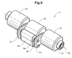
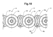
도 9 내지 도 12는 이격 롤러의 선회축을 하중경감시키기 위한 홀딩 벨트를 구비한 롤러 유닛을 도시한다.
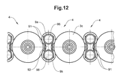
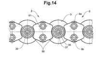
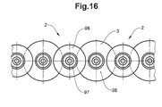
도 13 내지 도 16은 지지 롤러 상에 고정되지 않은 베어링 요소 및 이격 롤러를 도시한다.
도면들에 사용된 도면 부호와 그 의미가 도면 부호의 설명에 명확하게 열거된다. 기본적으로, 도면들에서, 동일한 부품에는 동일한 도면 부호가 부여된다.Hereinafter, the subject matter of the present invention will be described in more detail by preferred embodiments schematically illustrated in the accompanying drawings.
1A-1D are views of the support device and three cross-sectional views through the support device.
2A-2C are two cross-sectional views through a view of the support device and another embodiment of the support device.
3 shows the use of a conveyor device consisting of several supporting devices.
4a and 4b show an intermediate element.
5 is a cross sectional view through a support device with a roller bearing;
It is sectional drawing through the support apparatus of another embodiment of this invention.
7 shows the roller unit.
8 shows, in plan view, two roller units arranged in a line.
9-12 show a roller unit with a holding belt for reducing the load on the pivot axis of the separation roller.
13 to 16 show a bearing element and a spaced roller that are not fixed on a support roller.
Reference numerals used in the figures and their meanings are clearly listed in the description of the reference numerals. Basically, in the drawings, the same parts are given the same reference numerals.
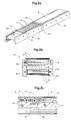
도 1a 내지 도 1d는 지지 장치(12)의 도면과 이 지지 장치(12)를 통한 3가지 단면도를 도시한다. 지지 장치(12)는 측부 요소(74)를 구비하는 지지 본체(7)와, 지지 본체(7) 내에서 회전하고 벨트(6)에 의해 둘러싸이는 롤러 본체(5)를 포함한다. 모든 롤러(3)가 중앙 본체(73) 주위로의 회전 경로를 따라 도시되지는 않으며, 실제로 롤러(3)는 본질적으로 전체 회전 경로를 따라 제공된다. 도시된 실시예에서, 롤러 본체(5)는 그것의 전체 주연부에 걸쳐 벨트(6)에 의해 둘러싸이지만, 그것은 단지 부분 영역에서만 둘러싸이거나 덮여질 수도 있다. 벨트(6)는 정상부까지 지지 영역(11)을 따라 바람직하게는 롤러 본체(5)의 전체 폭을 덮어, 이것이 오염물질로부터 보호되도록 한다. 도 1b의 종단면도와 도 1c 및 도 1d의 단면도에서 볼 수 있는 바와 같이, 롤러 본체(5)는 큰 롤러와 작은 롤러를 교대로 구비하며, 여기에서 큰 롤러는 지지 롤러(3)의 역할을 하고, 이 지지 롤러는 벨트(6) 및 지지 롤러(3)에 작용하는, 운반되는 또는 지지되는 물체(미도시)로부터의 하중력을 지지 본체(7)의 중앙 본체(73) 상으로 전달한다. 중앙 본체(73)는 측부 요소(74)에 의해 플로어 상에 또는 설비 내에 지지된다. 지지 롤러(3)는 이하에서 이격 롤러(9)로 불리우는 보다 작은 롤러에 의해 서로 이격된다. 지지 롤러(3)와 이격 롤러(9)는 서로 상에서 롤링하며, 측부 요소(74) 내에 형성되고 중앙 본체(73)를 중심으로 롤러의 회전 경로를 따라 연장되는 가이드 홈(71) 내에서 안내된다. 이러한 안내는 지지 롤러(3)의 축방향으로 돌출된 선회 스터브(pivot stub)(35)와, 가이드 홈(71) 내로 돌출되어 롤러(3, 9)가 회전 경로를 이탈하지 못하도록 하는 이격 롤러(9)의 선회 스터브(95)에 의해 달성된다. 선회 스터브(35, 95)는 단품으로서 롤러(3, 9) 상에 설계되거나(도 1c), 또는 연속하는 롤러 선회축(36)으로서 롤러(3, 9) 내에 삽입된다(도 1d). 지지 장치(12)의 상부 영역 또는 지지 영역(11)에서, 벨트(6)는 지지 롤러(3) 상에 놓이고, 하부 영역 또는 복귀 영역에서 그것은 롤러 본체(5)로부터 얼마간 이격될 수 있다(도 1b 내지 도 1d).1A-1D show a view of the
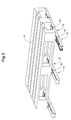
도 2a 내지 도 2c는 지지 장치의 도면과 중앙 본체(73)의 지지 표면(72) 내에 요홈(82)을 구비한 지지 장치의 다른 실시 형태를 통한 2가지 단면도를 도시한다. 여기에서도, 모든 롤러(3)가 중앙 본체(73) 주위로의 회전 경로를 따라 도시되지는 않는다. 도 2a는 또한 두 지지 장치(12)가 그들 사이에 중간 요소(61)를 배치한 상태로 함께 직렬 연결되는 것을 도시한다. 그러한 연결은 물론 도 1a 내지 도 1d에 따른 지지 장치(12)에서도 가능하다.2A-2C show two cross-sectional views through a view of the support device and another embodiment of the support device with
도 2c는 측부 요소(74)가 제거된 상태에서 요홈(82)의 영역에서의 측면도를 도시하고, 도 2b는 요홈(82)의 영역에서의 단면도를 도시한다. 요홈(82)은 롤러(3)가 벨트(6)와 지지 표면(72) 사이에서 롤링하는 동안 틸팅(tilting)하는 경우에 롤러(3)를 하중경감(relieving)시키고 정렬시키는 역할을 한다. 이러한 틸팅은 예를 들어 지지 롤러(3)가 가이드 쪽으로 측방향으로 주행하여 단부면 또는 그들의 에지가 가이드 상에 마찰됨으로써 지지 장치(12)의 마모를 증가시킨다. 요홈(82)은 예를 들어 별개의 릴리프(relief) 요소(8)로 설계되지만, 중앙 본체(73) 또는 측부 요소(74)에서 요홈형성될 수도 있다.FIG. 2C shows a side view in the area of the
지지 표면(72)은 지지 영역(11)에서 롤러(3)를 지지하며, 따라서 직접 또는 벨트(6)에 의해 컨베이어 수단 또는 운반 물품(미도시)을 또한 지지한다. 요홈(82)의 영역에서, 그곳에 위치된 각각의 롤러(43)에는 하중이 없다. 그곳의 롤러(3)는 중력으로 인해 그리고/또는 롤러(3)의 측방향 안내에 의해, 벨트(6)로부터 떨어져 얼마간 하향으로 이동된다. 이에 의해, 롤러는 더욱 쉽게 이동되고, 롤러의 회전축이 비스듬한 위치에 있는 상태로 롤러가 하중-지지 영역으로 진입한 경우에 다시 정렬될 수 있으며, 즉 롤러의 회전축이 롤러(3)의 롤링 방향에 수직하게 연장되도록 정렬될 수 있다.The
단지 하나의 릴리프 요소(8)만이 도 2a에 도시되지만, 수개의 릴리프 요소(8)가 지지 영역(11)을 따라 배치될 수도 있다.Although only one
도 1a 내지 도 1d와 도 2a 내지 도 2c에 따른 지지 장치(12)는 무한 순환 롤러(3)를 포함한다. 물론 유사한 방식으로, 요동(to and fro) 운동하는 롤러를 구비한, 따라서 비-순환 롤러를 구비한 또는 단지 순전히 선형으로 이동되는 롤러를 구비한 지지 장치가 또한 제공될 수 있고, 선택적으로 요홈(82)을 구비할 수 있다. 이에 의해, 롤러 방향에 무관하게 일어나는 동일한 효과에 의해서, 요홈의 대칭은 이동 방향(전방 또는 후방)으로 효과를 나타낸다.The
요홈(82)은 별개의 요소 또는 릴리프 요소(8)로서 도 2a 내지 도 2c에 도시된다. 그러나, 본 발명의 다른 실시 형태들에서, 그것들은 또한 지지 표면(72) 상에 그리고 측부 요소(74) 상에 형성될 수 있으며, 따라서 요홈(82)을 형성하는데 별개의 구성요소를 필요로 하지 않고서 형성될 수 있다.The
도 3은 수개의 지지 장치(12)의 컨베이어 장치의 적용을 도시한다. 따라서, 한편으로는 수개의 지지 장치(12)는 각각의 경우에 운반 제품(10)을 장착하기 위해 중간 요소(61)를 지지 장치(12) 사이에 구비하고서 직렬로 배치된다. 다른 한편으로는, 수개의 그러한 일련의 지지 장치(12)는 넓은 운반 제품(10)을 지지 및 운반할 수 있도록 서로 평행하게 배치된다.3 shows the application of the conveyor apparatus of several supporting
도 4a 및 도 4b는 예를 들어 단일 중간 롤러(62)를 구비한 중간 요소(61)를 도시한다. 중간 롤러(62)는 슬라이딩 베어링에 의해 도시된 바와 같이, 베어링(64)에 의해 선회축(63)을 중심으로 회전할 수 있다. 본 발명의 다른 실시 형태들에서, 베어링은 중간 요소(61)의 정치된 부분 내의 또는 중간 롤러(62) 내의 롤링 베어링이다. 중간 요소(61)의 측부 부분의 외부 형상은(운반 방향으로 볼 때) 지지 장치(12)의 측부 요소(74)의 외부 형상에 대응하여, 그것들은 확고한 끼워맞춤(positive fit)에 의해 함께 결합될 수 있다. 다른 확고한 끼워맞춤 요소(미도시) 및/또는 스크류 체결용 플랜지가 연결을 위해 제공될 수 있다.4a and 4b show an
도 5는 롤러 베어링(37)을 구비한 지지 장치를 통한 단면도를 도시한다. 롤러 베어링이 지지 롤러(3)의 롤러 선회축(36) 상에 배치되는 방식이 예시적으로 도시된다. 이격 롤러(9)가 또한 동일한 방식으로 안내 홈(71) 내에 장착될 수 있다. 본 발명의 이 실시 형태에 의하면, 롤러 본체(5)가 미는 힘에 의해 이동 방향으로 하중을 받을 때 발생하는 마찰력 및 마모가 더욱 감소되고, 이에 의해 롤러 축(36)은 가이드 홈(71)의 평면에 수직한 방향으로 밀려진다.5 shows a cross section through a support device with a
도 6은 본 발명의 다른 실시 형태에서 지지 장치를 통한 단면도를 도시한다. 여기에서, 각각의 경우에, 두 이격 롤러(9)가 두 지지 롤러(3) 사이에 배치된다. 이격 롤러(9)는 지지 롤러(3) 상에서 롤링한다. 이격 롤러(9)는 그것들의 축이 각각의 경우에 지지 롤러(3)의 축을 통한 평면[지지 표면(72)에 평행] 위와 아래에 있는 상태로 지지 영역(11)에 놓인다[요홈(82)의 영역에서 하강된 지지 롤러(3)는 제외]. 각각의 경우에, 두 이격 롤러(9)는 수직 방향으로, 따라서 지지 표면(72)에 수직하게 함께 유지되어, 미는 힘이 지지 롤러(3) 사이에서 전달될 수 있다. 롤러 및 롤러 유닛이 미는(잡아당기는 것에 반대되는) 힘을 전달할 수 있다는 사실로 인해, 지지 장치(12)에 걸쳐 밀려지는 운반 물체가 마찬가지로 동일 지지 장치(12) 상에 위치되는 다른 물체를 하중(벨트) 영역에서 롤러 본체에 의해 간접적으로 구동시켜 그것들을 추가로 운반할 수 있다.6 shows a cross section through a support device in another embodiment of the invention. Here, in each case, two
도 6에 도시된 릴리프 요소(8) 또는 그것들의 요홈은 도 2a 내지 도 2c에 의해 설명된 바와 동일한 방식으로 작용한다. 그러나, 도 6의 지지 장치(12)는 릴리프 요소(8) 없이 실현될 수도 있다.The
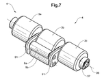
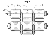
도 7은 롤러 유닛(4)을 도시하고, 도 8은 줄지어 배치되는 2개의 롤러 유닛(4)을 평면도로 도시한다. 롤러 유닛에서, 각각의 경우에, 지지 롤러(3)와 2개의 이격 롤러(9)(여기에서 도면 부호 9a 및 9b로 개별적으로 표기됨)가 서로 이동가능하게 연결되며, 즉 3개 모두가 베어링 요소(91) 내에 장착된다. 베어링 요소(91)는 기본적으로 롤러 축(36)의 단부에 근접하게 배치될 수 있어, 단품 지지 롤러(3) 및 2개의 이격 롤러(9)가 베어링 요소(91) 사이에 놓인다. 그러나, 도시된 실시예에서, 베어링 요소(91)는 단부로부터 이격되어, 지지 롤러(3)는 롤러 축(36)에 의해 서로 연결되는, 동일한 직경의 최소한 3개의 동축 영역(3a, 3b, 3c)을 구비한다. 각각의 경우에, 이들 영역 중 2개 사이에서, 베어링 요소(91)가 롤러 선회축(36) 상에 회전가능하게 배치되고, 롤러 영역을 넘어 반경 방향으로 돌출된다. 2개의 이격 롤러(9)가 2개의 베어링 요소 사이에 장착된다(서로 동축으로 배치되고 서로 함께 이동되는 롤러 - 지지 롤러 또는 이격 롤러 - 의 수개의 영역은 각각의 경우에 롤러로서 간주됨).FIG. 7 shows the
도 9 내지 도 12는 이격 롤러의 선회축의 하중경감을 위한 홀딩 벨트(92)를 구비한 롤러 유닛을 도시한다. 도 9 및 도 10은, 도 7 및 도 8의 그것과 유사하지만 두 이격 롤러(9a, 9b) 주위로 권취되는 홀딩 벨트(92)를 구비한 롤러 유닛(4)의 도면을 도시한다. 이격 롤러(9a, 9b) 중 최소한 하나, 여기에서는 하부 롤러의 베어링 위치는 긴 구멍(93)으로서 설계된다. 비하중인가 상태에서, 하부 롤러는 하향으로 미끄러진다. 하중인가 상태에서, 도 10에 도시된 바와 같이, 이격 롤러(9a, 9b)는 지지 롤러(3)에 의해 또는 이들의 중간 영역(3b)에 의해 밀려져 이격되지만(상부 쪽으로 그리고 하부 쪽으로), 홀딩 벨트(92)에 의해 함께 유지된다. 홀딩 벨트(92)는 지지 롤러(3)와 이격 롤러(9) 사이를 통해 그리고 부분적으로 이격 롤러(9)를 따라 연장된다. 도 10에서, 지지 롤러(3)의 롤러 영역의 축(63)과 베어링 요소(91) 사이에 스냅 연결부(94)가 파선으로 도시된다. 이들은 롤러 유닛(4)의 간단한 조립을 가능하게 한다.9 to 12 show a roller unit with a holding
도 11 및 도 12는, 이격 롤러(9) 그것 자체 주위로는 연장되지 않고 이격 롤러(9)의 선회축 연장부(96) 주위로 연장되는 홀딩 벨트(93)를 구비한 다른 실시 형태를 도시한다. 따라서, 여기에서도, 홀딩 벨트(93)는 선회축이 주어진 범위를 넘어 서로로부터 이격되지 못하도록 함으로써 이격 롤러(9)의 선회 베어링을 하중경감시킨다. 여기에서도, 이격 롤러는 베어링 요소(91) 내에 장착되고, 바람직하게는 지지 롤러 영역(3a, 3b, 3c)에 연결된다.11 and 12 show another embodiment with a holding
도 13 내지 도 16은 지지 롤러(3) 상에 고정되지 않은 베어링 요소(91) 및 이격 롤러(9)를 도시한다. 이격 롤러(9)와 함께 베어링 요소(91)는 이격 요소(2)를 형성한다. 이격 요소(2)는 지지 롤러(3)에 대해 느슨한 방식으로 이동가능하고, 롤러 본체(5)는 롤러의 회전 경로를 따라 잡아당겨져 이격될 수 있다. 도 13 내지 도 16에서, 베어링 요소(91) 또는 베어링(97)의 쇼울더(98, 99)가 지지 롤러(3)의 포위 실린더 내로 반경 방향으로 돌출되고, 이에 의해 롤러 축(36)의 방향을 따른 지지 롤러(3)의 이동을 제한한다. 쇼울더(98, 99)가 없는 변형예와는 대조적으로, 단지 회전 운동이 쇼울더(98, 99)와 지지 롤러(3) 사이에서 일어난다. 쇼울더(98, 99)가 없으면, 지지 롤러(3)는 또한 병진 운동에 의해 측부 요소(74)와 마찰될 수 있다.13 to 16 show the bearing
도 13 및 도 14는 지지 롤러(3)와 이격 요소(2)의 도면을 도시하며, 여기에서 이격 요소(2)의 베어링 요소(91)는 각각의 경우에 지지 롤러(3)를 축방향으로 둘러싸는 2개의 쇼울더(99)를 포함한다. 이 쇼울더는 지지 롤러(3)의 롤러 축(36)을 향해 지향되는 오목한 영역을 포함한다. 여기에서도, 홀딩 벨트가 이격 롤러(9) 또는 그것들의 선회축 주위에 적용될 수 있다. 이격 롤러(9)는 베어링 요소(91)의 에지를 조금 넘어서, 지지 표면(72)에 수직한 방향으로 돌출된다. 만일 롤러 본체가 운반 방향으로 하중경감되면, 이격 요소(2)는 지지 표면(72) 상으로 하향으로 활주되며, 또한 이 위치에서 지지 표면(72)을 따라 롤링하고 베어링 요소(91)의 일부분에 의해 미끄러진다. 만일 운반 방향으로 하중을 받는 상태에서 지지 롤러(3)가 다시 서로에 가압되면, 지지 롤러(3)의 롤러 선회축(36), 또는 또한 지지 롤러(3)의 롤러 베어링(37)(또는 슬라이딩 베어링, 미도시)은 이격 롤러(9)가 롤러 축(36)을 통한 평면에 대칭적으로 놓일 때까지, 베어링 요소(91)의 오목한 영역 내로 미끄러져 들어가 베어링 요소(91)를 다시 위로 들어올린다.13 and 14 show a view of the
도 15 및 도 16은 지지 롤러(3) 및 이격 요소(2)의 도면을 도시하며, 여기에서 이격 요소(2)는 각각의 경우에 베어링, 특히 슬라이딩 베어링(97)을 구비한 개개의 이격 롤러(9)를 포함한다. 슬라이딩 베어링(97)은 각각의 경우에 지지 롤러(3)를 축방향으로 둘러싸서 그것들을 안내하는 주연부 쇼율더(99)를 포함한다. 도시된 실시예에서, 지지 롤러(3)는 또한 이격 롤러(9)의 슬라이딩 베어링(97)과 동일한 가이드 홈(71) 내에서 롤링하거나 활주되는 슬라이딩 베어링(38)을 포함한다. 본 발명의 다른 실시 형태들도 또한 슬라이딩 베어링을 구비하여 실현될 수 있고, 도 15 및 도 16의 이 실시 형태도 또한 롤러 베어링을 구비하여 실현될 수 있다. 본 발명의 다른 실시 형태에서, 이격 롤러는 베어링을 구비하지 않고, 쇼울더(99)가 이격 롤러(9) 상에 형성되어, 이격 롤러(9)와 함께 회전한다.15 and 16 show a view of the
특히 고하중용 경량 컨베이어 내에 플라스틱 롤러를 구비한 설계의 지지 롤러(3)의 직경은 예를 들어 10 mm 내지 30 mm, 바람직하게는 약 20 mm이고, 이격 롤러(9)의 직경은 5 mm 내지 15 mm이다. 개별 지지 장치(12)의 길이는 예를 들어 300 mm 내지 500 mm 이상이며, 여기에서 무한한 거리를 연결시키기 위해 수개의 지지 장치(12)가 연이어 적용될 수 있다.In particular, the diameter of the
1: 컨베이어 장치 11: 지지 영역
12: 지지 장치 2: 이격 요소
3: 지지 롤러 3a, 3b, 3c: 롤러 영역
35: 지지 롤러의 선회 스터브 36: 롤러 축
37: 롤러 베어링 38: 슬라이딩 베어링
4: 롤러 유닛 5: 롤러 본체
6: 벨트 61: 중간 요소
62: 중간 롤러 63: 선회축
64: 베어링 7: 지지 본체
71: 가이드 홈 72: 지지 표면
73: 중앙 본체 74: 측부 요소
8: 릴리프 요소 81: 가이드 홈의 하강부
82: 지지 표면의 요홈 83: 경로 협소부
9, 9a, 9b: 이격 롤러 91: 베어링 요소
92: 홀딩 벨트 93: 긴 구멍
94: 스냅 연결부 95: 이격 롤러의 선회 스터브
96: 선회축 연장부 97: 슬라이딩 베어링
98, 99: 쇼울더 10: 운반 물품1: Conveyor Unit 11: Support Area
12: support device 2: separation element
3:
35: Swivel stub of support roller 36: Roller shaft
37: roller bearing 38: sliding bearing
4: roller unit 5: roller body
6: belt 61: middle element
62: intermediate roller 63: pivot
64: bearing 7: support body
71: guide groove 72: support surface
73: central body 74: side elements
8: relief element 81: lowering of guide groove
82: groove of the support surface 83: path narrowing
9, 9a, 9b: Spaced roller 91: Bearing element
92: holding belt 93: long hole
94: snap connection 95: turning stub of the separation roller
96: pivot shaft extension 97: sliding bearing
98, 99: shoulder 10: carrying goods
Claims (19)
롤러 본체(5)는 일련의 지지 롤러(3) 및 이격 롤러(9)를 포함하고,
이격 롤러(9)는 지지 롤러(3)보다 작은 직경을 갖고, 이격 롤러(9)는 각각의 경우에 연속하는 지지 롤러(3)를 서로로부터 이격시키며,
지지 장치(12)는 지지 영역(11)을 따라 이동되는 하물을 지지하기 위해 제공되고, 최소한 지지 영역(11)에서 롤러 본체(5)는 그것의 전체 폭에 걸쳐 벨트(6)에 의해 덮여지며, 따라서 지지 롤러(3)는 지지 영역(11)에서 지지 본체(7) 상에서 그리고 벨트(6) 상에서 롤링하는 것을 특징으로 하는 지지 장치.As a heavy-duty conveying support apparatus 12 including a support main body 7 and a roller main body 5 rotating around the support main body 7,
The roller body 5 comprises a series of support rollers 3 and a spaced roller 9,
The spacer roller 9 has a smaller diameter than the support roller 3, and the spacer roller 9 in each case separates the continuous support roller 3 from each other,
A support device 12 is provided for supporting a load that is moved along the support region 11, at least in the support region 11 the roller body 5 is covered by the belt 6 over its entire width. The support roller (3) thus rolls on the support body (7) and on the belt (6) in the support region (11).
각각의 경우에 2개의 이격 롤러(9)가 2개의 연속하는 지지 롤러(3) 사이에 배치되는 것을 특징으로 하는 지지 장치.The method of claim 1,
Support device, characterized in that in each case two separation rollers (9) are arranged between two successive support rollers (3).
지지 롤러(3)의 선회축은 지지 롤러가 이동하는 기준 표면을 규정하고, 이격 롤러(9)의 외부 군의 선회축은 기준 표면 외측에서 연장되며, 이격 롤러(9)의 내부 군의 선회축은 기준 표면 내측에서 연장되는 것을 특징으로 하는 지지 장치.The method of claim 2,
The pivot axis of the support roller 3 defines the reference surface on which the support roller moves, the pivot axis of the outer group of the separation roller 9 extends outside the reference surface, and the pivot axis of the inner group of the separation roller 9 is the reference surface. A support device, characterized in that extending from the inside.
각각의 경우에 2개의 이격 롤러(9)가 최소한 하나의 공동-이동되는 베어링 요소(91) 상에 회전가능하게 장착되는 것을 특징으로 하는 지지 장치.The method according to claim 2 or 3,
Support device, characterized in that in each case two separation rollers (9) are rotatably mounted on at least one co-moved bearing element (91).
각각의 경우에 2개의 이격 롤러(9) 외에, 지지 롤러(3)가 또한 각각의 경우에 최소한 하나의 공동-이동되는 베어링 요소(91) 상에 이동가능하게 고정되고, 상기 롤러들은 함께 롤러 유닛(4)을 형성하는 것을 특징으로 하는 지지 장치.The method of claim 4, wherein
In addition to the two spaced rollers 9 in each case, the support rollers 3 are also movably fixed on at least one co-moving bearing element 91 in each case, which roller units together (4) forming a supporting device.
각각의 경우에 홀딩 벨트(92)가 서로에게 배정된 2개의 이격 롤러(9) 주위로, 또는 상기 이격 롤러(9)의 선회축 주위로 권취되는 것을 특징으로 하는 지지 장치.The method according to any one of claims 2 to 5,
In each case a holding belt (92) is wound around two spaced rollers (9) assigned to each other or around a pivot axis of the spaced rollers (9).
롤러 유닛(4)의 지지 롤러(3) 및 하부 이격 롤러(9) 둘 다가 지지 표면(72) 상에 놓이는 경우에, 상부 이격 롤러(9)의 회전축은 지지 롤러(3)의 회전축을 통해 지지 표면(72)에 평행하게 연장되는 평면 위에 놓이는 것을 특징으로 하는 지지 장치.The method according to claim 5 or 6,
When both the support roller 3 and the lower separation roller 9 of the roller unit 4 rest on the support surface 72, the axis of rotation of the upper separation roller 9 is supported through the axis of rotation of the support roller 3. Support device characterized in that it lies on a plane extending parallel to the surface (72).
이격 롤러(8)는 2개의 지지 롤러(3) 또는 롤러 유닛(4)이 잡아당겨져 이격될 때 지지 표면(72) 쪽으로 미끄러지거나 틸팅되고, 이격 롤러(9)는 롤러 유닛(4)이 충돌할 때 다시 위로 들어올려지거나 똑바로 놓여지는(set up) 것을 특징으로 하는 지지 장치.8. The method according to any one of claims 4 to 7,
The separation roller 8 slides or tilts toward the support surface 72 when the two support rollers 3 or roller units 4 are pulled apart and spaced apart, and the separation roller 9 causes the roller unit 4 to collide. A support device which is lifted up again when set up or upright when set up.
롤러 유닛(4)에서, 지지 롤러(3)는 롤러 선회축(36)에 의해 서로 연결되는 최소한 3개의 동축 영역(3a, 3b, 3c)을 포함하고, 각각의 경우에 상기 영역들 중 2개 사이에서 베어링 요소(91)가 롤러 선회축(36) 상에 회전가능하게 배치되며, 2개의 이격 롤러(9)는 2개의 베어링 요소(91) 사이에 장착되는 것을 특징으로 하는 지지 장치.The method according to any one of claims 5 to 8,
In the roller unit 4, the support roller 3 comprises at least three coaxial regions 3a, 3b, 3c which are connected to each other by a roller pivot 36, in each case two of said regions Between the bearing elements (91) are rotatably arranged on the roller pivot (36), and the two separation rollers (9) are mounted between the two bearing elements (91).
지지 본체(7)는 2개의 주연부 가이드 홈(71)을 포함하고, 지지 롤러(3)는 선회 스터브(35)에 의해 가이드 홈(71) 내에서 안내되며, 바람직하게는 또한 이격 롤러(9)가 선회 스터브(95)에 의해 가이드 홈(71) 내에서 또는 다른 가이드 홈 내에서 안내되는 것을 특징으로 하는 지지 장치.The method according to any of the preceding claims,
The support body 7 comprises two circumferential guide grooves 71, and the support roller 3 is guided in the guide groove 71 by the turning stub 35, preferably also the spaced roller 9. Is guided in the guide groove (71) or in another guide groove by a pivot stub (95).
지지 롤러(3) 및/또는 이격 롤러(9)는 롤러 베어링(37)에 의해 또는 슬라이딩 베어링(38, 97)에 의해 가이드 홈 내에 장착되는 것을 특징으로 하는 지지 장치.The method of claim 10,
A support device, characterized in that the support rollers (3) and / or the spaced rollers (9) are mounted in the guide grooves by roller bearings (37) or by sliding bearings (38, 97).
각각의 경우에 정확히 하나의 이격 롤러(9)가 2개의 연속하는 지지 롤러(3) 사이에 배치되는 것을 특징으로 하는 지지 장치.The method of claim 1,
Support device, characterized in that in each case exactly one separation roller (9) is arranged between two successive support rollers (3).
베어링 요소(91) 또는 베어링(97)의 쇼울더(98, 99)가 지지 롤러(3)의 포위 실린더 내로 반경 방향으로 돌출되고, 이에 의해 롤러 축(36)의 방향을 따른 지지 롤러(3)의 이동을 제한하는 것을 특징으로 하는 지지 장치.The method according to any of the preceding claims,
The shoulders 98, 99 of the bearing element 91 or of the bearing 97 protrude radially into the surrounding cylinder of the support roller 3, whereby the support roller 3 along the direction of the roller axis 36 is formed. A support device, characterized in that it limits movement.
지지 장치(12)는 줄지어 직렬로 배치되고, 최소한 하나의 이동가능한 지지 요소를 구비하는, 특히 중간 롤러(62)를 구비하는 중간 요소(61)가 지지 장치(12) 사이에 배치되는 것을 특징으로 하는 컨베이어 장치.As a conveyor apparatus (1) comprising two or more supporting devices (12) according to any one of claims 1 to 11,
The support device 12 is arranged in series, and is characterized in that an intermediate element 61 with at least one movable support element, in particular with an intermediate roller 62, is arranged between the support devices 12. Conveyor device.
지지 장치(12) 및 중간 요소(61)는 모듈식 구성 시스템을 형성하고, 이에 의해 지지 장치(12) 및 중간 요소(61)는 컨베이어 장치(1)를 형성하기 위해 무한한 수로 함께 결합될 수 있는 것을 특징으로 하는 컨베이어 장치.The method of claim 14,
The support device 12 and the intermediate element 61 form a modular construction system whereby the support device 12 and the intermediate element 61 can be joined together in an unlimited number to form the conveyor device 1. Conveyor device, characterized in that.
지지 장치(12) 및 중간 요소(61)는 확고한 끼워맞춤에 의해 함께 결합될 수 있는 것을 특징으로 하는 컨베이어 장치.The method according to claim 14 or 15,
Conveyor device, characterized in that the support device (12) and the intermediate element (61) can be joined together by a firm fit.
중간 요소(61)는 지지 장치(12) 내에 통합되고, 통합된 중간 요소(61)를 구비한 지지 장치(12)는 바람직하게는 확고한 끼워맞춤에 의해 함께 결합될 수 있는 것을 특징으로 하는 컨베이어 장치.The method according to any one of claims 14 to 16,
The intermediate element 61 is integrated in the support device 12, and the conveyor device 12 with the integrated intermediate element 61 can be joined together preferably by a firm fit. .
각각의 경우에 수개의 지지 장치(12) 및 중간 요소(61)를 구비한 수개의 열이 컨베이어 장치(1) 내에 서로 평행하게 배치되는 것을 특징으로 하는 컨베이어 장치.18. The method according to any one of claims 14 to 17,
Conveyor device, characterized in that in each case several rows with several supporting devices (12) and intermediate elements (61) are arranged parallel to one another in the conveyor device (1).
컨베이어 장치(1)는 최소한 부분 영역들에서 경사지는 것을 특징으로 하는 컨베이어 장치.18. The method according to any one of claims 14 to 17,
The conveyor apparatus (1) is characterized by inclining at least in partial regions.
Applications Claiming Priority (2)
| Application Number | Priority Date | Filing Date | Title |
|---|---|---|---|
| CH1307/09 | 2009-08-24 | ||
| CH01307/09A CH701686A1 (en) | 2009-08-24 | 2009-08-24 | Supporting device for conveying heavy loads. |
Publications (1)
| Publication Number | Publication Date |
|---|---|
| KR20110020744A true KR20110020744A (en) | 2011-03-03 |
Family
ID=41667177
Family Applications (1)
| Application Number | Title | Priority Date | Filing Date |
|---|---|---|---|
| KR1020100080712A KR20110020744A (en) | 2009-08-24 | 2010-08-20 | Support device for conveying heavy loads |
Country Status (12)
| Country | Link |
|---|---|
| US (1) | US8162133B2 (en) |
| EP (1) | EP2289822B1 (en) |
| JP (1) | JP2011042504A (en) |
| KR (1) | KR20110020744A (en) |
| CN (1) | CN102009829A (en) |
| AU (1) | AU2010212338B2 (en) |
| BR (1) | BRPI1002933A2 (en) |
| CA (1) | CA2712156A1 (en) |
| CH (1) | CH701686A1 (en) |
| RU (1) | RU2010134830A (en) |
| SG (1) | SG169283A1 (en) |
| TW (1) | TW201124319A (en) |
Families Citing this family (14)
| Publication number | Priority date | Publication date | Assignee | Title |
|---|---|---|---|---|
| CH701358A1 (en) * | 2009-06-25 | 2010-12-31 | Wrh Walter Reist Holding Ag | Conveyor and supporting. |
| US9056620B2 (en) * | 2012-12-06 | 2015-06-16 | Gary D. Copus | Material handling and load conveyance system |
| US9555976B2 (en) * | 2013-07-26 | 2017-01-31 | Solus Industrial Innovations, Llc | Bearing stand-off devices |
| CN103964129A (en) * | 2014-04-02 | 2014-08-06 | 浙江申振机械科技有限公司 | Convex chain for roller type EMS goods conveyor |
| US10233035B2 (en) | 2014-04-10 | 2019-03-19 | Flexible Steel Lacing Company | Conveyor transfer guards |
| MX2016013166A (en) | 2014-04-10 | 2017-06-15 | Flexible Steel Lacing Co | Conveyor transfer guards. |
| USD789643S1 (en) | 2015-04-10 | 2017-06-13 | Flexible Steel Lacing Company | Conveyor transfer guard |
| USD780399S1 (en) | 2015-04-10 | 2017-02-28 | Flexible Steel Lacing Company | Conveyor transfer guard |
| CN105173552A (en) * | 2015-10-15 | 2015-12-23 | 四川麦笠机械设备有限公司 | Conveying device for conveying pressure-receiving plates |
| JP6272532B1 (en) * | 2017-05-18 | 2018-01-31 | 有田工業株式会社 | Columnar material support device |
| US10427891B2 (en) | 2017-06-29 | 2019-10-01 | Flexible Steel Lacing Company | Transfer guard system and mount thereof |
| IT201800009501A1 (en) * | 2018-10-16 | 2020-04-16 | Movex Spa | RETURN GUIDE DEVICE FOR CONVEYING CARPETS |
| KR20230087506A (en) | 2020-09-22 | 2023-06-16 | 후렉크시불스티일레이싱캄파니 | Roller Conveyor Gap Breaker |
| KR102477309B1 (en) * | 2022-01-28 | 2022-12-13 | 서용덕 | Carrier for loading and unloading cargo |
Family Cites Families (13)
| Publication number | Priority date | Publication date | Assignee | Title |
|---|---|---|---|---|
| GB1338218A (en) * | 1970-11-11 | 1973-11-21 | Sieder J S | Arrangements for handling bulk load containers |
| JPS5539855Y2 (en) * | 1975-04-14 | 1980-09-18 | ||
| JPS51130580A (en) | 1975-05-08 | 1976-11-12 | Kuraray Co Ltd | Process for assimilating and decomposing of oxidatively degraded polyv inyl alcohol by the use of microorganisms |
| WO1981002333A1 (en) * | 1980-02-14 | 1981-08-20 | G Lowry | Rolling friction device |
| FR2504998A1 (en) * | 1981-04-30 | 1982-11-05 | Migaud Claude | Roller bearing support pad - has plain roller bearings retained in housing by needle rollers |
| DE3608487A1 (en) * | 1986-03-14 | 1987-09-17 | Hymmen Theodor Gmbh | DEVICE FOR APPLYING A SURFACE PRESS TO PROGRESSIVE WORKPIECES |
| GB2201199B (en) * | 1987-02-19 | 1990-08-22 | Hasp Int Ltd | Improvements in or relating to load bearing roller assemblies |
| JPS6413325A (en) * | 1987-07-07 | 1989-01-18 | Hiroshi Hayakawa | Integral conveyor |
| DE19500050A1 (en) * | 1995-01-03 | 1996-07-04 | Guedel Alfred Ag | Roller circulation system with guide rollers |
| US7210569B1 (en) * | 2004-02-09 | 2007-05-01 | Tarpaulin.Com, Inc. | Transfer device for conveyor belt |
| DE202007011352U1 (en) * | 2006-09-05 | 2007-10-11 | Julius Blum Gmbh | Pull-out guide for drawers |
| US20080145197A1 (en) * | 2006-12-15 | 2008-06-19 | Harry Randall Taylor | Roller rack |
| US8210341B2 (en) * | 2009-12-08 | 2012-07-03 | Laitram, L.L.C. | Conveyor transfer system with floating transfer platform |
-
2009
- 2009-08-24 CH CH01307/09A patent/CH701686A1/en not_active Application Discontinuation
-
2010
- 2010-07-30 CA CA2712156A patent/CA2712156A1/en not_active Abandoned
- 2010-08-03 EP EP10405148.7A patent/EP2289822B1/en not_active Not-in-force
- 2010-08-05 TW TW099126096A patent/TW201124319A/en unknown
- 2010-08-10 SG SG201005808-9A patent/SG169283A1/en unknown
- 2010-08-13 AU AU2010212338A patent/AU2010212338B2/en not_active Expired - Fee Related
- 2010-08-20 KR KR1020100080712A patent/KR20110020744A/en not_active Application Discontinuation
- 2010-08-20 JP JP2010184883A patent/JP2011042504A/en active Pending
- 2010-08-23 RU RU2010134830/11A patent/RU2010134830A/en not_active Application Discontinuation
- 2010-08-23 US US12/861,320 patent/US8162133B2/en not_active Expired - Fee Related
- 2010-08-24 CN CN2010102620532A patent/CN102009829A/en active Pending
- 2010-08-24 BR BRPI1002933-8A patent/BRPI1002933A2/en not_active IP Right Cessation
Also Published As
| Publication number | Publication date |
|---|---|
| SG169283A1 (en) | 2011-03-30 |
| TW201124319A (en) | 2011-07-16 |
| US8162133B2 (en) | 2012-04-24 |
| JP2011042504A (en) | 2011-03-03 |
| AU2010212338A1 (en) | 2011-03-10 |
| CA2712156A1 (en) | 2011-02-24 |
| CH701686A1 (en) | 2011-02-28 |
| US20110042187A1 (en) | 2011-02-24 |
| EP2289822A1 (en) | 2011-03-02 |
| EP2289822B1 (en) | 2013-05-29 |
| RU2010134830A (en) | 2012-02-27 |
| BRPI1002933A2 (en) | 2012-06-19 |
| AU2010212338B2 (en) | 2016-05-12 |
| CN102009829A (en) | 2011-04-13 |
Similar Documents
| Publication | Publication Date | Title |
|---|---|---|
| KR20110020744A (en) | Support device for conveying heavy loads | |
| KR101423940B1 (en) | Conveyor | |
| US8272503B2 (en) | Support device for a conveyor installation and method for operation of a conveyor installation | |
| KR101335779B1 (en) | Sorter belt conveyor | |
| JP5632743B2 (en) | Accumulation and release conveyor | |
| CA2560186A1 (en) | Rolling conveying device | |
| EP3472072B1 (en) | Motor driven roller support | |
| AU2018355899B2 (en) | Enclosed belt rail conveyor system | |
| KR20090124374A (en) | Belt conveyor | |
| JP2001139122A (en) | Transportation device | |
| US20010025767A1 (en) | Method and apparatus for transferring pallets around an end terminal in a conveyor assembly | |
| KR20130110500A (en) | Apparatus for adjusting serpentine moving of belt conveyer | |
| CN110282382A (en) | A kind of shaftless carrying roller ultra-wide belt feeder of bracket type | |
| KR101592259B1 (en) | Moving cart having pulley with a wire rope slip prevention function | |
| JP4795321B2 (en) | Loading device | |
| KR20200138975A (en) | Curve conveyor | |
| KR100368228B1 (en) | Conveyor for Conveying Packages at Curves | |
| JP6964959B2 (en) | Transfer device | |
| KR20120069295A (en) | Meandering prevention device for conveyer belt | |
| MXPA05001921A (en) | Device and method for positioning separately supplied elongate meat products. |
Legal Events
| Date | Code | Title | Description |
|---|---|---|---|
| A201 | Request for examination | ||
| E902 | Notification of reason for refusal | ||
| E601 | Decision to refuse application |