KR20100098498A - Batteries having inorganic/organic porous films - Google Patents
Batteries having inorganic/organic porous films Download PDFInfo
- Publication number
- KR20100098498A KR20100098498A KR1020107009415A KR20107009415A KR20100098498A KR 20100098498 A KR20100098498 A KR 20100098498A KR 1020107009415 A KR1020107009415 A KR 1020107009415A KR 20107009415 A KR20107009415 A KR 20107009415A KR 20100098498 A KR20100098498 A KR 20100098498A
- Authority
- KR
- South Korea
- Prior art keywords
- electrode
- layer
- separator
- porous
- electrochemical cell
- Prior art date
Links
Images


Classifications
-
- H—ELECTRICITY
- H01—ELECTRIC ELEMENTS
- H01M—PROCESSES OR MEANS, e.g. BATTERIES, FOR THE DIRECT CONVERSION OF CHEMICAL ENERGY INTO ELECTRICAL ENERGY
- H01M10/00—Secondary cells; Manufacture thereof
- H01M10/05—Accumulators with non-aqueous electrolyte
- H01M10/052—Li-accumulators
- H01M10/0525—Rocking-chair batteries, i.e. batteries with lithium insertion or intercalation in both electrodes; Lithium-ion batteries
-
- C—CHEMISTRY; METALLURGY
- C08—ORGANIC MACROMOLECULAR COMPOUNDS; THEIR PREPARATION OR CHEMICAL WORKING-UP; COMPOSITIONS BASED THEREON
- C08J—WORKING-UP; GENERAL PROCESSES OF COMPOUNDING; AFTER-TREATMENT NOT COVERED BY SUBCLASSES C08B, C08C, C08F, C08G or C08H
- C08J9/00—Working-up of macromolecular substances to porous or cellular articles or materials; After-treatment thereof
-
- H—ELECTRICITY
- H01—ELECTRIC ELEMENTS
- H01M—PROCESSES OR MEANS, e.g. BATTERIES, FOR THE DIRECT CONVERSION OF CHEMICAL ENERGY INTO ELECTRICAL ENERGY
- H01M4/00—Electrodes
- H01M4/02—Electrodes composed of, or comprising, active material
- H01M4/13—Electrodes for accumulators with non-aqueous electrolyte, e.g. for lithium-accumulators; Processes of manufacture thereof
-
- H—ELECTRICITY
- H01—ELECTRIC ELEMENTS
- H01M—PROCESSES OR MEANS, e.g. BATTERIES, FOR THE DIRECT CONVERSION OF CHEMICAL ENERGY INTO ELECTRICAL ENERGY
- H01M50/00—Constructional details or processes of manufacture of the non-active parts of electrochemical cells other than fuel cells, e.g. hybrid cells
- H01M50/40—Separators; Membranes; Diaphragms; Spacing elements inside cells
- H01M50/409—Separators, membranes or diaphragms characterised by the material
- H01M50/411—Organic material
- H01M50/414—Synthetic resins, e.g. thermoplastics or thermosetting resins
- H01M50/417—Polyolefins
-
- H—ELECTRICITY
- H01—ELECTRIC ELEMENTS
- H01M—PROCESSES OR MEANS, e.g. BATTERIES, FOR THE DIRECT CONVERSION OF CHEMICAL ENERGY INTO ELECTRICAL ENERGY
- H01M50/00—Constructional details or processes of manufacture of the non-active parts of electrochemical cells other than fuel cells, e.g. hybrid cells
- H01M50/40—Separators; Membranes; Diaphragms; Spacing elements inside cells
- H01M50/409—Separators, membranes or diaphragms characterised by the material
- H01M50/44—Fibrous material
-
- H—ELECTRICITY
- H01—ELECTRIC ELEMENTS
- H01M—PROCESSES OR MEANS, e.g. BATTERIES, FOR THE DIRECT CONVERSION OF CHEMICAL ENERGY INTO ELECTRICAL ENERGY
- H01M50/00—Constructional details or processes of manufacture of the non-active parts of electrochemical cells other than fuel cells, e.g. hybrid cells
- H01M50/40—Separators; Membranes; Diaphragms; Spacing elements inside cells
- H01M50/409—Separators, membranes or diaphragms characterised by the material
- H01M50/446—Composite material consisting of a mixture of organic and inorganic materials
-
- H—ELECTRICITY
- H01—ELECTRIC ELEMENTS
- H01M—PROCESSES OR MEANS, e.g. BATTERIES, FOR THE DIRECT CONVERSION OF CHEMICAL ENERGY INTO ELECTRICAL ENERGY
- H01M50/00—Constructional details or processes of manufacture of the non-active parts of electrochemical cells other than fuel cells, e.g. hybrid cells
- H01M50/40—Separators; Membranes; Diaphragms; Spacing elements inside cells
- H01M50/409—Separators, membranes or diaphragms characterised by the material
- H01M50/449—Separators, membranes or diaphragms characterised by the material having a layered structure
-
- H—ELECTRICITY
- H01—ELECTRIC ELEMENTS
- H01M—PROCESSES OR MEANS, e.g. BATTERIES, FOR THE DIRECT CONVERSION OF CHEMICAL ENERGY INTO ELECTRICAL ENERGY
- H01M50/00—Constructional details or processes of manufacture of the non-active parts of electrochemical cells other than fuel cells, e.g. hybrid cells
- H01M50/40—Separators; Membranes; Diaphragms; Spacing elements inside cells
- H01M50/46—Separators, membranes or diaphragms characterised by their combination with electrodes
-
- H—ELECTRICITY
- H01—ELECTRIC ELEMENTS
- H01M—PROCESSES OR MEANS, e.g. BATTERIES, FOR THE DIRECT CONVERSION OF CHEMICAL ENERGY INTO ELECTRICAL ENERGY
- H01M50/00—Constructional details or processes of manufacture of the non-active parts of electrochemical cells other than fuel cells, e.g. hybrid cells
- H01M50/40—Separators; Membranes; Diaphragms; Spacing elements inside cells
- H01M50/489—Separators, membranes, diaphragms or spacing elements inside the cells, characterised by their physical properties, e.g. swelling degree, hydrophilicity or shut down properties
- H01M50/491—Porosity
-
- Y—GENERAL TAGGING OF NEW TECHNOLOGICAL DEVELOPMENTS; GENERAL TAGGING OF CROSS-SECTIONAL TECHNOLOGIES SPANNING OVER SEVERAL SECTIONS OF THE IPC; TECHNICAL SUBJECTS COVERED BY FORMER USPC CROSS-REFERENCE ART COLLECTIONS [XRACs] AND DIGESTS
- Y02—TECHNOLOGIES OR APPLICATIONS FOR MITIGATION OR ADAPTATION AGAINST CLIMATE CHANGE
- Y02E—REDUCTION OF GREENHOUSE GAS [GHG] EMISSIONS, RELATED TO ENERGY GENERATION, TRANSMISSION OR DISTRIBUTION
- Y02E60/00—Enabling technologies; Technologies with a potential or indirect contribution to GHG emissions mitigation
- Y02E60/10—Energy storage using batteries
-
- Y—GENERAL TAGGING OF NEW TECHNOLOGICAL DEVELOPMENTS; GENERAL TAGGING OF CROSS-SECTIONAL TECHNOLOGIES SPANNING OVER SEVERAL SECTIONS OF THE IPC; TECHNICAL SUBJECTS COVERED BY FORMER USPC CROSS-REFERENCE ART COLLECTIONS [XRACs] AND DIGESTS
- Y02—TECHNOLOGIES OR APPLICATIONS FOR MITIGATION OR ADAPTATION AGAINST CLIMATE CHANGE
- Y02P—CLIMATE CHANGE MITIGATION TECHNOLOGIES IN THE PRODUCTION OR PROCESSING OF GOODS
- Y02P70/00—Climate change mitigation technologies in the production process for final industrial or consumer products
- Y02P70/50—Manufacturing or production processes characterised by the final manufactured product
Abstract
본 발명은 (a) 양극, (b) 음극, (c) 상기 양극과 상기 음극 사이에 삽입된 다공성 무기/유기 복합층 및 (d) 리튬염 및 비수성 용제를 포함하는 전해질을 갖는 Li-이온과 같은 전기화학전지에 관한 것이다. 상기 복합층은 무기 입자 및 결합제를 포함하여 나노복합 분리막(NCS)를 형성한다. 상기 복합층 이외에, 상기 전기화학전지는 다공성 분리막을 포함한다.The present invention provides a Li-ion having (a) an anode, (b) a cathode, (c) a porous inorganic / organic composite layer interposed between the anode and the cathode, and (d) an electrolyte comprising a lithium salt and a non-aqueous solvent. It relates to an electrochemical cell such as. The composite layer includes an inorganic particle and a binder to form a nanocomposite separator (NCS). In addition to the composite layer, the electrochemical cell includes a porous separator.
Description
상호 참조Cross-reference
본 출원은 2007년 9월 28일자로 출원된 미국 가출원 제60/995,777호의 정규 출원이다.
This application is a formal application of US Provisional Application No. 60 / 995,777, filed September 28, 2007.
기술분야Technical Field
본 발명은 일반적으로 전기화학전지에 관한 것이다. 보다 구체적으로는, 본 발명은 배터리 전지 및 전기화학적 배터리 전지용 분리막(separator) 배열에 관한 것이다.
The present invention relates generally to electrochemical cells. More specifically, the present invention relates to separator arrays for battery cells and electrochemical battery cells.
발명의 배경Background of the Invention
분리막(separator membrane)들은 배터리의 중요한 부품이다. 이들 막들은 상기 배터리의 애노드와 캐소드의 접촉을 막으면서 전해질을 통과시키는 작용을 한다. 추가로, 사이클 수명 및 전력과 같은 배터리 성능 속성은 분리막의 선택에 의해 현저한 영향을 받을 수 있다. 안전성 또한 분리막 속성과 연관될 수 있고, 특정 분리막들은 애노드에서의 Li 금속 도금의 발생과 심지어 덴드라이트(dendrite) 형성을 감소시키는 것으로 공지되어 있다.Separator membranes are an important part of the battery. These membranes serve to pass the electrolyte while preventing contact between the anode and the cathode of the battery. In addition, battery performance attributes such as cycle life and power can be significantly affected by the choice of separator. Safety can also be associated with separator properties, and certain separators are known to reduce the occurrence of Li metal plating and even dendrite formation at the anode.
배터리 전지의 분리막들은, 일부 경우, 다공성 중합체 물질로부터 형성된다. 기타 경우, 분리막들은 섬유상 또는 입자상 물질로부터 형성되며, 이러한 물질은 유리 섬유, 무기 섬유(예: 석면), 세라믹, 합성 중합체성 섬유 뿐만 아니라 천연 중합체성 섬유(예: 셀룰로즈)를 포함할 수 있다.The separators of the battery cell are, in some cases, formed from a porous polymeric material. In other cases, the separators are formed from fibrous or particulate materials, which may include glass fibers, inorganic fibers (such as asbestos), ceramics, synthetic polymeric fibers, as well as natural polymeric fibers (such as cellulose).
현재 사용되는 분리막들에는 다수의 문제가 있다. 이러한 막들의 재료는 종종 고가이며, 전형적인 배터리 시스템이 비교적 큰 용적의 막들을 포함한다는 사실을 고려하면 상기 막들의 비용은 전체 배터리 비용의 상당 부분을 차지할 수 있다.Currently used separators have a number of problems. The material of these membranes is often expensive, and given the fact that typical battery systems include relatively large volumes of membranes, the cost of these membranes can account for a significant portion of the overall battery cost.
저비용 배터리 분리막 물질은 덴드라이트 브릿징을 방지하는 데 비효율적일 수 있으므로, 비교적 두껍게 만들어야 한다. 그러나, 이러한 두께가 상기 배터리의 내부 저항을 증가시킴으로써, 이의 효율을 감소시키며, 배터리 크기도 증가시킨다. Low cost battery separator materials can be inefficient in preventing dendrite bridging and must be made relatively thick. However, this thickness increases the internal resistance of the battery, thereby reducing its efficiency and also increasing the battery size.
따라서, 효율적이고 저비용이며 안전하고 용이하게 사용되는 분리막 배열이 요구된다. 현재, 리튬 이온 전지용 분리막은 평균 ~$2.00/m2로 고가이며, 이는 고에너지 전지에서 비용의 약 11%이고 고전력 전지 비용의 ~23%이다. 리튬 이온 배터리 비용을 추가로 감소시키기 위해, 저렴한 분리막의 개발이 요구된다.
Therefore, there is a need for a membrane arrangement that is efficient, low cost, safe and easily used. Currently, separators for lithium ion batteries are expensive with an average of ~ $ 2.00 / m 2 , which is about 11% of the cost in high energy cells and ~ 23% of the cost of high power cells. In order to further reduce the cost of lithium ion batteries, the development of inexpensive separators is required.
발명의 예시 양태의 요약Summary of Illustrative Aspects of the Invention
전기화학전지용 유기/무기 복합 필름 및 다공성 또는 비다공성 분리막 조합물이 기술된다. 이러한 필름은 무기 입자들과 중합체성 결합제의 복합체이다. 상기 복합 물질은 저비용이고, 추가로 전극에 대한 접착성이 우수하고 안전성을 개선시키며 고온에서 치수 안정성이 높은 고성능 분리막을 제공하는 기능이 있다. 상기 전극/필름 어셈블리는 상기 층들 사이의 접착성이 우수하고, 와인딩(winding)되거나 구브리거나 굴곡시키거나 기타 방식으로 변형시키는 경우에도 이의 기판(집전체)으로부터 탈층되지 않는다. 또한, 다공성 분리막은 전지 어셈블리를 용이하게 조립하도록 상기 복합 필름에 인접하게 배치된다.Organic / inorganic composite films and porous or nonporous separator combinations for electrochemical cells are described. Such a film is a composite of inorganic particles and a polymeric binder. The composite material is low cost, and further has the function of providing a high performance separator having good adhesion to the electrode, improving safety and high dimensional stability at high temperature. The electrode / film assembly is excellent in adhesion between the layers and does not delaminate from its substrate (current collector) even when winding, bending, bending or otherwise deforming. In addition, the porous separator is disposed adjacent to the composite film to easily assemble the battery assembly.
한 양태에서, Li-이온과 같은 전기화학전지는 양극, 음극, 상기 양극과 상기 음극 사이에 배치된 다공성 무기/유기 복합층, 및 리튬염 및 비수성 용제를 포함하는 전해질을 갖는다. 상기 복합층은 무기 나노입자들과 결합제를 포함하여 나노복합 분리막(NCS)을 형성한다. 상기 복합층 이외에, 상기 전기화학전지는 상기 2개의 NCS 피복된 전극들 사이에 다공성 또는 비다공성 분리막을 포함한다.In one embodiment, an electrochemical cell such as a Li-ion has a positive electrode, a negative electrode, a porous inorganic / organic composite layer disposed between the positive electrode and the negative electrode, and an electrolyte including a lithium salt and a non-aqueous solvent. The composite layer includes inorganic nanoparticles and a binder to form a nanocomposite membrane (NCS). In addition to the composite layer, the electrochemical cell includes a porous or nonporous separator between the two NCS coated electrodes.
또 다른 양태에서, 전기화학전지에서 사용하기 위한 전극/분리막 어셈블리가 제공된다. 상기 어셈블리는 집전체, 및 상기 집전체에 부착된 다공성 복합 전극을 포함한다. 상기 전극은 적어도 전기활성 입자들과 결합제를 포함한다. 상기 어셈블리는 또한 중합체 매트릭스 중에 실질적으로 균질하게 분포되어 나노기공을 형성하는 무기 입자들을 포함하는 다공성 복합층을 포함하며, 상기 복합층은 복합층과 전극층 사이의 계면에서 용제 접착제(solvent weld)에 의해 상기 전극층에 고정된다. 상기 용제 접착제는 상기 결합제와 상기 중합체의 혼합물을 포함한다. 다공성 또는 비다공성 분리막은 상기 NCS 피복된 전극들 사이에 배치된다.In another aspect, an electrode / membrane assembly for use in an electrochemical cell is provided. The assembly includes a current collector and a porous composite electrode attached to the current collector. The electrode comprises at least electroactive particles and a binder. The assembly also includes a porous composite layer comprising inorganic particles that are substantially homogeneously distributed in the polymer matrix to form nanopores, wherein the composite layer is formed by solvent weld at the interface between the composite layer and the electrode layer. It is fixed to the electrode layer. The solvent adhesive comprises a mixture of the binder and the polymer. Porous or nonporous separators are disposed between the NCS coated electrodes.
한 양태에서, 상기 복합 필름은 전기화학적으로 안정한 중합체 매트릭스 중에 입자 크기가 1㎛ 미만인 전기화학적으로 안정한 무기 입자들을 포함하며, 상기 복합 필름은 적어도 이정(bimodal) 기공 분포를 가지며, 이때 제1의 보다 작은 크기의 기공은 상기 층 중에서 실질적으로 균질하게 분포하며, 하나 이상의 보다 큰 기공 크기는 상기 층 중에서 랜덤하게 분포한다. 상기 기공들의 치수는 나노미터 범위이다.In one embodiment, the composite film comprises electrochemically stable inorganic particles having a particle size of less than 1 μm in an electrochemically stable polymer matrix, wherein the composite film has at least bimodal pore distribution, wherein the first more Small pore sizes are substantially homogeneously distributed in the layer, and one or more larger pore sizes are randomly distributed in the layer. The dimensions of the pores are in the nanometer range.
한 양태에서, 제1의 보다 작은 크기의 기공은 약 5 내지 100nm의 범위이고, 보다 큰 기공 크기는 약 100 내지 500nm의 범위이다. 상기 입자들은 실질적으로 단분산성이며, 입자 크기가 약 10 내지 50nm 범위이다. 상기 복합층은 기공 용적 분율이 25% 초과이다.In one embodiment, the first smaller pore size ranges from about 5 to 100 nm and the larger pore size ranges from about 100 to 500 nm. The particles are substantially monodisperse and have a particle size in the range of about 10-50 nm. The composite layer has a pore volume fraction of greater than 25%.
한 양태에서, 상기 결합제는 무기/유기 복합체 조성물의 5 내지 60%이다. 상기 복합층은 무기 입자들과 중합체 결합제를 약 95:5 내지 약 40:60의 무기 입자들:중합체의 중량 비로 가질 수 있다. In one embodiment, the binder is 5 to 60% of the inorganic / organic composite composition. The composite layer may have inorganic particles and a polymer binder in a weight ratio of inorganic particles: polymer of about 95: 5 to about 40:60.
한 양태에서, 상기 필름의 무기 재료는 실리카, 알루미나, 산화티탄, 천연 및 합성 제올라이트 및 적합한 입자 크기의 기타 전기화학적으로 안정한 무기 입자로 이루어진 그룹으로부터 선택된다.In one embodiment, the inorganic material of the film is selected from the group consisting of silica, alumina, titanium oxide, natural and synthetic zeolites and other electrochemically stable inorganic particles of suitable particle size.
한 양태에서, 상기 다공성 분리막은 직경이 50 내지 100Å인 기공을 갖는 미세다공성 폴리올레핀 분리막이며, 폴리프로필렌 및 폴리에틸렌 중의 하나 이상으로 이루어진 필름 또는 이들의 라미네이트를 포함한다.In one embodiment, the porous separator is a microporous polyolefin separator having pores having a diameter of 50 to 100 microns and includes a film or laminate thereof made of one or more of polypropylene and polyethylene.
한 양태에서, 상기 분리막은 폴리에틸렌 옥사이드를 포함한다.In one embodiment, the separator comprises polyethylene oxide.
한 양태에서, 상기 다공성 분리막은 마찰, 응집 및 점착 중의 하나 이상에 의해 함께 지지되는 섬유로부터 제조된 부직포(non-woven textile) 물질이다. 상기 다공성 분리막은 두께가 약 9 내지 15㎛의 범위이고, 상기 복합 필름은 두께가 약 2 내지 16㎛의 범위일 수 있다.In one embodiment, the porous separator is a non-woven textile material made from fibers supported together by one or more of friction, agglomeration and adhesion. The porous separator may have a thickness in the range of about 9 to 15 μm, and the composite film may have a thickness in the range of about 2 to 16 μm.
또 다른 양태에서, 분리막 배열은 한개 또는 두개의 전극들 위에 배치된 복합층을 포함하는 전기화학전지에 제공된다. 상기 복합층은 중합체 매트릭스 중에 약 10 내지 약 200nm 범위의 입자 크기를 갖는 세라믹 입자들을 포함한다. 상기 입자들은 전형적으로 직경이 1㎛ 미만일 수 있으며, 보다 전형적으로 15 내지 30nm이다. 일부 양태에서, 상기 층은 적어도 이정 기공 분포를 가지며, 여기서 제1의 보다 작은 크기의 기공은 상기 층에서 실질적으로 균질하게 분포되며, 하나 이상의 보다 큰 기공 크기는 상기 층에 랜덤하게 분포되며, 이들 기공은 양쪽 다 나노미터 크기이다. 다공성 분리막은 상기 복합층과 전극들 사이에 배치된다.In another aspect, a separator arrangement is provided for an electrochemical cell comprising a composite layer disposed over one or two electrodes. The composite layer comprises ceramic particles having a particle size in the polymer matrix in the range of about 10 to about 200 nm. The particles may typically be less than 1 μm in diameter, more typically 15 to 30 nm. In some embodiments, the layer has at least bipolar pore distribution, wherein the first smaller sized pores are substantially homogeneously distributed in the layer, and one or more larger pore sizes are randomly distributed in the layer, and The pores are both nanometers in size. The porous separator is disposed between the composite layer and the electrodes.
또 다른 양태에서, 전기화학전지용 전극/분리막 어셈블리의 제조방법이 제공된다. 상기 방법은 적어도 전기활성 입자들과 결합제를 포함하는 다공성 복합 전극층을 제공하는 단계; 및 피복 용액을 제공하는 단계를 포함한다. 상기 피복 용액은 중합체, 상기 중합체용 용제 시스템, 및 상기 용제에 분산된 무기 입자를 포함하며, 여기서 상기 용제 시스템은 전극층의 결합제에 대해 적어도 어느 정도의 용해도를 갖도록 선택된다. 상기 방법은 상기 전극층의 표면을 상기 피복 용액 층으로 피복하는 단계를 추가로 포함한다. 상기 피복 용액은 상기 전극층의 두께의 일정 분율에 침투하여 상기 결합제의 일부를 용해시킨다. 상기 용제를 상기 피복 용액 층으로부터 제거하여 다공성 분리막 층을 침착시킨다. 상기 복합층은 중합체 중에 실질적으로 균질하게 분포된 무기 입자들을 포함하며 기공 용적 분율이 25% 이상이다. 상기 용제 접착제는 상기 다공성 전극층과 상기 다공성 복합층 사이의 계면에 형성된다. 다공성 또는 비다공성 분리막은 상기 다공성 복합층에 인접하게 제공된다. In another aspect, a method of manufacturing an electrode / membrane assembly for an electrochemical cell is provided. The method includes providing a porous composite electrode layer comprising at least electroactive particles and a binder; And providing a coating solution. The coating solution comprises a polymer, the solvent system for the polymer, and inorganic particles dispersed in the solvent, wherein the solvent system is selected to have at least some solubility in the binder of the electrode layer. The method further includes coating the surface of the electrode layer with the coating solution layer. The coating solution penetrates a certain fraction of the thickness of the electrode layer to dissolve a portion of the binder. The solvent is removed from the coating solution layer to deposit a porous separator layer. The composite layer comprises inorganic particles substantially homogeneously distributed in the polymer and has a pore volume fraction of at least 25%. The solvent adhesive is formed at the interface between the porous electrode layer and the porous composite layer. Porous or nonporous separators are provided adjacent to the porous composite layer.
상기 방법의 양태에서 피복 용액 중의 무기 입자들과 중합체의 중량비는 약 65:35 내지 약 45:55이다. 상기 피복 용액은 상기 전극층 두께의 90%까지 침투하고 분무 피복, 닥터 블레이딩, 슬롯 다이 피복(slot die coating), 그라비어 피복(gravure coating), 잉크 제트 인쇄, 스핀 피복, 침지 피복 및 스크린 인쇄로 이루어진 그룹으로부터 선택된 기술 또는 기타 기술들에 의해 수행될 수 있다. 상기 전극 표면의 분무 피복은 상기 전극의 표면 상의 복수의 피복 용액 층의 분무 피복을 포함할 수 있다. 본 발명의 추가 양태에 따라, 상기 피복된 층은 각각의 분무 피복 단계 사이에서 건조될 수 있다. 상기 용제의 제거는 상기 용제를 증발시키고/시키거나 상기 용제를 상기 중합체에 대해 비용제인 물질로 추출하는 과정을 포함할 수 있다.
In an embodiment of the method the weight ratio of the inorganic particles to the polymer in the coating solution is about 65:35 to about 45:55. The coating solution penetrates up to 90% of the electrode layer thickness and consists of spray coating, doctor blading, slot die coating, gravure coating, ink jet printing, spin coating, immersion coating and screen printing. It may be performed by a technique selected from the group or other techniques. Spray coating of the electrode surface may comprise spray coating of a plurality of coating solution layers on the surface of the electrode. According to a further aspect of the invention, the coated layer can be dried between each spray coating step. Removal of the solvent may include evaporating the solvent and / or extracting the solvent as a non-solvent material for the polymer.
도면의 간단한 설명 Brief description of the drawings
본 발명은 하기 열거한 도면을 참조로 기술되며, 이는 예시용으로만 제공되며 본 발명을 제한할 의도는 없다.The invention is described with reference to the drawings listed below, which are provided for illustrative purposes only and are not intended to limit the invention.
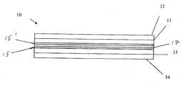
도 1은 본 발명의 하나 이상의 양태에 따르는 다공성 분리막을 포함하는 전기화학전지의 도식도이다.1 is a schematic diagram of an electrochemical cell including a porous separator according to one or more embodiments of the present invention.
도 2a는 본 발명의 하나 이상의 양태에 따르는 다공성 분리막을 포함하는 전기화학전지의 도식도이다.2A is a schematic diagram of an electrochemical cell including a porous separator according to one or more embodiments of the present invention.
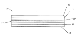
도 2b는 본 발명의 하나 이상의 양태에 따르는 다공성 분리막을 포함하는 전기화학전지의 도식도이다.2B is a schematic of an electrochemical cell comprising a porous separator according to one or more embodiments of the present invention.
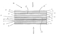
도 3은 본 발명의 하나 이상의 양태에 따르는 스태킹된 전기화학전지를 도시한 횡단면도이다.3 is a cross-sectional view illustrating a stacked electrochemical cell in accordance with one or more aspects of the present invention.
도 4는 분리막을 제조하기 위한 하나 이상의 양태에서 사용되는 분무 피복 공정의 흐름도이다.4 is a flow chart of a spray coating process used in one or more embodiments for making separators.
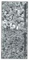
도 5는 본 발명의 한 측면에 따르는 분리막 배열의 현미경 사진을 포함한다.5 includes a micrograph of a membrane array according to one aspect of the present invention.
도 6은 본 발명의 한 측면에 따르는 시험 전지와 비교용 전지를 나타낸 온도 차트이다.6 is a temperature chart showing a test cell and a comparative cell according to one aspect of the present invention.
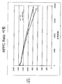
도 7은 본 발명의 한 측면에 따르는 시험 전지와 비교용 전지에 대한 방전 용량(mAh) 대 전력의 플롯이다7 is a plot of discharge capacity (mAh) versus power for test and comparative cells in accordance with an aspect of the present invention.
도 8은 본 발명의 한 측면에 따르는 시험 전지 및 비교용 전지에 대한 방전 용량(mWh) 대 전력의 플롯이다.8 is a plot of discharge capacity (mWh) versus power for test and comparative cells in accordance with one aspect of the present invention.
도 9는 본 발명의 한 측면에 따르는 시험 전지 및 비교용 전지에 대한 방전 용량(mAh) 대 사이클의 플롯이다.9 is a plot of discharge capacity (mAh) versus cycle for test and comparative cells in accordance with an aspect of the present invention.
도 10은 본 발명의 한 측면에 따르는 시험 전지 및 비교용 전지에 대한 방전 용량(mAh) 대 사이클의 플롯이다.
10 is a plot of discharge capacity (mAh) versus cycle for test and comparative cells in accordance with an aspect of the present invention.
예시 양태의 상세한 설명Detailed Description of Example Embodiments
무기/유기 다공성 필름들은 전극 상에 피복되어 Li-이온 배터리에서 분리막으로 사용될 수 있다. 이들은 전지 비용을 현저하게 감소시키고 전지 안정성을 개선시키는 이들의 잠재력으로 인해 바람직할 수 있다. 무기 충전재 및 중합체 결합제의 복합물인 나노복합 분리막(NCS)은 본원에 참조로 인용되는, 각각 2007년 8월 21일 및 2008년 8월 21일자로 출원되고 발명의 명칭이 "전기화학전지용 분리막 및 이의 제조방법"인 미국 특허원 제60/957,101호 및 제12/196,203호에 기술되어 있다. 상기 NCS는 실질적으로 무균열 필름 및 피복된 엣지를 통한 누출 전류를 감소시켜야 할 필요성을 제기하면서 다공성 막 대체용으로 고려되어 왔다. 현저한 진보가 이루어져 왔지만(이는 별도의 특허원의 주제이다), 또 다른 해법은 전극들 중의 하나 또는 둘 다에 상기 NCS 피복 기술을 시행하고 추가로 다공성 분리막을 사용하는 것이다. 상기 피복된 전극(들)과 다공성 또는 비다공성 분리막이 전기화학전지용으로 고안되었다. 예시되는 다공성 분리막은 미세다공성 폴리에틸렌, 또는 폴리프로필렌 필름을 포함한다. 상기 분리막은 다공성 대신 완전 치밀할 수 있으면서, 예를 들면, 폴리에틸렌 옥사이드를 포함할 수 있다. 상기 NCS 피복층은 애노드 또는 캐소드 상에서 사용될 수 있다.Inorganic / organic porous films may be coated on the electrodes and used as separators in Li-ion batteries. These may be desirable because of their potential to significantly reduce cell costs and improve cell stability. Nanocomposite membranes (NCS), a composite of an inorganic filler and a polymeric binder, are filed on August 21, 2007 and August 21, 2008, respectively, incorporated herein by reference, and are entitled "Membranes for Electrochemical Cells and Their Manufacturing methods "in US Patent Application Nos. 60 / 957,101 and 12 / 196,203. The NCS has been considered as a replacement for porous membranes, raising the need to substantially reduce leakage currents through crack-free films and coated edges. Although significant advances have been made (which is the subject of a separate patent application), another solution is to implement the NCS coating technique on one or both of the electrodes and further use porous separators. The coated electrode (s) and porous or nonporous separators are designed for electrochemical cells. Exemplary porous separators include microporous polyethylene, or polypropylene films. The separator may be completely dense instead of porous, and may include, for example, polyethylene oxide. The NCS coating layer can be used on the anode or the cathode.
캐소드 활성층(11), 캐소드 기판 또는 집전체(12), 애노드 활성층(13) 및 애노드 기판 또는 집전체(14)를 포함하는 예시 전기화학전지(10)을 도시한 도 1을 참조한다. 상기 캐소드 및/또는 애노드 활성층은 전형적으로 전극 활성 물질, 전도성 첨가제 및 중합체 결합제를 포함하는 다공성 입자상 복합체를 포함한다. NCS 층(15) 및 다공성 분리막(17)은 상기 전극층을 분리시킨다. NCS 층은 도 1에 도시한 바와 같은 단 하나의 전극 위에 제공될 수 있으며, 이는 동일하게 애노드 또는 캐소드일 수 있다. 대안으로, NCS 층(15 및 15')은 도 2a에 나타낸 바와 같이 양쪽 전극 위에 제공될 수 있다. 액체 전해질은 상기 NCS 층(15 및 15') 및 다공성 분리막(17)을 투과한다. 상기 집전체는 이의 각각의 전극층과 접촉하여 상기 전기화학전지의 충전 및 방전 사이클 동안 전류가 흐르게 한다. 상기 전지는 함께 스태킹되거나 와인딩되어 프리즘형 또는 나선상 권선형 배터리를 형성할 수 있다. 이러한 경우, 상기 전극은 양면이 전기활성층으로 피복될 수 있다. 도 2b는 캐소드(11) 위에만 NCS 층(15')을 보여준다.Reference is made to FIG. 1, which shows an exemplary
상기 NCS의 중합체 결합제는 특정 배터리 시스템의 화학적 특성과 상용성인 중합체들로부터 선택된다. 상기 중합체는 전기 절연성이어야 하며, 전해질 용제 중에서의 용해도가 낮아야 하며, 상기 전지 중에서 화학적으로 및 전기화학적으로 안정해야 한다. 리튬 및 리튬 이온 배터리 시스템 뿐만 아니라 기타 배터리 시스템에서도 유용한 중합체들의 한 그룹은 스티렌 부타디엔 및 기타 스티렌계 중합체들과 같은 불소화 중합체 및 라텍스 중합체를 포함한다. 폴리비닐리덴 플루오라이드 중합체 조성물은 특정 유용성을 갖는 중합체들의 한 그룹이다. 다양한 상기 물질이 당분야에 공지되고 입수 가능하며, 이러한 물질들은 필수적으로 균질한 PVDF 뿐만 아니라 블렌드 및 공중합체를 포함할 수 있다. 한 특정 물질은 상표 쿠레하(Kureha) 7208하에 판매된 PVDF 물질이다. 기타 등가물 및 유사한 물질이 마찬가지로 사용될 수 있다.The polymer binder of the NCS is selected from polymers that are compatible with the chemical properties of the particular battery system. The polymer should be electrically insulating, have low solubility in electrolyte solvents and be chemically and electrochemically stable in the cell. One group of polymers useful in lithium and lithium ion battery systems as well as other battery systems include fluorinated polymers and latex polymers such as styrene butadiene and other styrenic polymers. Polyvinylidene fluoride polymer compositions are a group of polymers with particular utility. Various such materials are known and available in the art, and these materials may include blends and copolymers as well as essentially homogeneous PVDF. One particular material is PVDF material sold under the trademark Kureha 7208. Other equivalents and similar materials can likewise be used.
상기 NCS의 무기 성분은 상기 막이 혼입되는 특정 배터리 시스템 및 화학적 특성과 상용성인 다양한 천연 및 인공 물질로부터 선택될 수 있다. 둘 이상의 적합한 무기 성분들의 혼합물은 고려된다. 상기 무기 성분은 세라믹 물질일 수 있다. 세라믹 물질 중의 한 특정한 그룹은 실리카를 포함하며, 퓸드(fumed) 실리카가 사용될 수 있는 실리카의 한 특정한 형태이다. 퓸드 실리카는 표면적이 높고, 일반적으로 고순도 실리카 물질이다. 퓸드 실리카는 일반적으로 친수성이고, 대부분의 전해질 용제 및 다수의 극성 중합체에 의해 용이하게 습윤될 수 있다. 하나 이상의 양태에서 사용되는 물질은 표면적이 약 200m2/g이다. 상기 입자들은 매우 작으며, 전형적으로 직경이 200nm 미만이고, 보다 전형적으로 약 10 내지 20nm, 예를 들면, 약 14nm이다. 하나 이상의 양태들에서, 상기 세라믹 물질은 입자 크기 분포가 좁고 실질적으로 구 형태인 퓸드 실리카이다. 퓸드 실리카는 사염화규소(SiCl4)를 주의 깊게 제어 반응시켜 제조할 수 있으며, 이로써 고도로 제어가능하고 좁은 입자 크기 분포가 생성된다. 한 양태에서, 입자 크기가 약 14nm인 퓸드 실리카가 사용될 수 있다.The inorganic component of the NCS can be selected from a variety of natural and artificial materials compatible with the particular battery system and chemical properties into which the membrane is incorporated. Mixtures of two or more suitable inorganic components are contemplated. The inorganic component may be a ceramic material. One particular group of ceramic materials includes silica, and one particular form of silica in which fumed silica can be used. Fumed silica has a high surface area and is generally a high purity silica material. Fumed silica is generally hydrophilic and can be easily wetted by most electrolyte solvents and many polar polymers. The material used in one or more embodiments has a surface area of about 200 m 2 / g. The particles are very small, typically less than 200 nm in diameter, and more typically about 10-20 nm, for example about 14 nm. In one or more embodiments, the ceramic material is fumed silica having a narrow particle size distribution and substantially spherical form. Fumed silica can be prepared by carefully controlled reaction of silicon tetrachloride (SiCl 4 ), resulting in a highly controllable and narrow particle size distribution. In one embodiment, fumed silica having a particle size of about 14 nm can be used.
예를 들면, 본원 명세서의 맥락에서 세라믹 물질인 것으로 고려되는 다면 올리고머성 실세세스퀴옥산(POSS)과 같은 기타 규소 화합물이 상기 막의 세라믹 성분으로서 사용될 수 있다. 기타 세라믹 물질은 천연 및 합성 제올라이트, 알루미나 등을 포함한다. 상기 세라믹 물질들은 단독으로 사용되거나 역시 균일하거나 혼합된 크기 및 형태로 배합해서 사용될 수 있다.For example, other silicon compounds, such as oligomeric silsesquioxanes (POSS), may be used as the ceramic component of the film, if considered to be a ceramic material in the context of the present specification. Other ceramic materials include natural and synthetic zeolites, alumina, and the like. The ceramic materials may be used alone or in combination in uniform or mixed sizes and shapes.
중합체 및 세라믹의 비율은 비교적 광범위하게 가변적일 수 있지만, 일부 양태에서 상기 세라믹 물질은 생성된 분리막의 주요 성분이다. 일부 경우, 세라믹 대 중합체의 비는, 중량 기준으로, 95:5 내지 40:60의 범위일 수 있다. 한 특정 경우, 상기 막은 중량 기준으로 약 65%의 퓸드 실리카와 35%의 PVDF를 포함할 것이다. 상기 세라믹 물질 및 중합체는 용제 시스템에서 배합되어, 상기 용해된 중합체/용제 시스템 중에 균질한 분포의 세라믹 입자들을 형성한다. 상기 피복 용액 중의 중합체와 세라믹의 분포가 고도로 균질하면 상기 생성된 막 중의 중합체와 세라믹 물질의 분포가 고도로 균질하다.The ratio of polymer and ceramic can vary relatively widely, but in some embodiments the ceramic material is a major component of the resulting separator. In some cases, the ratio of ceramic to polymer may range from 95: 5 to 40:60 by weight. In one particular case, the membrane will comprise about 65% fumed silica and 35% PVDF by weight. The ceramic material and polymer are combined in a solvent system to form a homogeneous distribution of ceramic particles in the dissolved polymer / solvent system. The highly homogeneous distribution of polymer and ceramic in the coating solution is highly homogeneous in the distribution of polymer and ceramic material in the resulting film.
상기 NCS 층(15)은 무기 나노입자들과 결합제를 포함한다. 상기 NCS 층은 전기화학적으로 안정한 중합체 매트릭스 중의 입자 크기가 1㎛ 미만인 전기화학적으로 안정한 무기 입자들을 포함할 수 있으며, 이정 기공 분포를 포함할 수 있고, 이때 제1의 보다 작은 크기의 기공은 상기 층 중에서 실질적으로 균질하게 분포하며, 하나 이상의 보다 큰 기공 크기는 상기 층 중에서 랜덤하게 분포한다. 상기 기공들의 치수는 나노미터 범위이다. 한 양태에서, 제1의 보다 작은 기공 크기는 약 5 내지 100nm의 범위이고, 보다 큰 기공 크기는 약 100 내지 500nm의 범위이다. 한 양태에서, 상기 입자들은 실질적으로 단분산성이며, 입자 크기가 약 10 내지 50nm의 범위이다. 상기 복합층은 기공 용적 분율이 25%를 초과할 수 있다. 상기 NCS 층의 결합제는, 한 양태에서, 무기/유기 복합 조성물의 5 내지 60%이다. 상기 복합층은 무기 입자들과 중합체 결합제를 약 95:5 내지 약 40:60의 무기 입자들:중합체의 중량 비로 포함할 수 있다.The
한 양태에서, 퓸드 실리카는 두 가지 용제의 혼합물 중의 중합체성 결합체와 함께 분산된다. 사용된 퓸드 실리카는 일반적으로 표면적이 약 200m2/g인 친수성 실리카이다. 전형적으로, 상기 결합제는 쿠레하 7208과 같은 폴리비닐리덴 플루오라이드(PVdF)이다. 상기 분리막 중의 실리카 대 결합제의 정확한 비는 약 50:50 내지 약 95:5의 범위일 수 있다. 전형적인 제형은 약 65:35이다. 상기 용제 시스템은 NMP를 함유하는 2원 블렌드이다. 상기 공용제 및 고형분 부하량은 사용되는 피복 기술의 유형에 따라 가변적으로 선택한다. 예를 들면, 콤마(comma) 및 다이-슬롯 피복시, 프로필 아세테이트 및 5 내지 10% 고체 용액이 사용되며; HVLP 또는 초음파 분무 피복시, 아세톤 및 약 2 내지 4% 고체 용액이 사용된다.In one embodiment, the fumed silica is dispersed with the polymeric binder in a mixture of the two solvents. The fumed silica used is generally hydrophilic silica with a surface area of about 200 m 2 / g. Typically, the binder is polyvinylidene fluoride (PVdF) such as Kureha 7208. The exact ratio of silica to binder in the separator may range from about 50:50 to about 95: 5. Typical formulation is about 65:35. The solvent system is a binary blend containing NMP. The co-agent and solids loadings are variably selected depending on the type of coating technique used. For example, for comma and di-slot coating, propyl acetate and 5 to 10% solid solution are used; In HVLP or ultrasonic spray coating, acetone and about 2-4% solid solution are used.
상기 다공성 분리막(17)은 통상 성형물, 직물, 부직물, 미세다공성 물질, 결합된 물질, 종이 또는 라미네이트로 분류되는 분리막 부류 중의 임의의 것이다. 이들 물질을 본 발명에 따라 분리막(17)으로서 작동시키려면, 이들은 전자 절연성이어야 하며 최소한의 이온 저항을 가져야 할 뿐만 아니라 전해질에 의해 용이하게 습윤되어야 한다. 상기 분리막(17)은 물리적 특성 및 기계적 특성이 균일해야 하고 기계적 안정성과 치수 안정성을 제공해야 할 뿐만 아니라 전지 환경 내에서 화학적 안정성과 전기화학적 안정성을 제공해야 한다.The
예시되는 분리막은 폴리프로필렌 필름, 폴리에틸렌 필름, 또는 폴리프로필렌과 폴리에틸렌의 라미네이트로서 제공되는 기공이 50 내지 100Å을 초과하는 미세다공성 폴리올레핀 분리막이다. 부직 분리막은, 예를 들면, 시트 또는 매트 형태로 펼쳐져 마찰, 응집 및 점착 중의 하나 이상에 의해 서로 지지되는 섬유로부터 제조된 직물 제품을 포함한다.Exemplary separators are microporous polyolefin separators having a pore of greater than 50-100 GPa provided as a polypropylene film, polyethylene film, or a laminate of polypropylene and polyethylene. Nonwoven separators include, for example, textile products made from fibers that are spread in the form of sheets or mats and supported by one or more of friction, agglomeration and adhesion.
예시 양태에서, 상기 미세다공성 또는 부직 분리막(17)은 두께가 9 내지 15㎛의 범위이다. 이러한 두께는 일정 크기에 대해 용량을 최대화시키기 때문에 유리하다. Li-이온 배터리에 요구되는 기계적으로 견고한 속성을 갖기 위해 실질적으로 9 내지 15㎛ 범위의 미세다공성 또는 부직 분리막(17)을 사용하는 것이 기존에는 고려되지 않았다. 그러나, 본 발명의 한 측면은 이전에는 Li-이온 배터리 용도에 허용되지 않았던 두께를 갖는 얇은 다공성 분리막(17)을 사용하는 것이다. 상기 NCS(15)와 상술한 분리막(17)을 조합시키면 NCS만을 사용하는 경우 요구되었던 완전 비균열 NCS를 제공해야할 필요성이 경감된다.In an exemplary embodiment, the microporous or
또 다른 예시 양태에서, 비다공성 분리막(17)은 두께가 9 내지 15㎛의 범위이다. Li-이온 배터리에 요구되는 기계적으로 견고한 속성을 갖기 위해 비다공성 폴리에틸렌 옥사이드, 폴리비닐리덴 플루오라이드, 치환된 폴리포스파젠 또는 유사한 이온 전도성 중합체 필름을 사용하는 것 또한 기존에는 고려되지 않았다. 그러나, 본 발명의 한 측면은 상기 NCS 층을 갖는 얇은 비다공성 분리막을 사용하는 것이다. 상기 NCS(15)와 상술한 분리막(17)을 조합시키면 NCS만을 사용하는 경우 요구되었던 완전 비균열 NCS를 제공해야할 필요성이 경감된다.In another exemplary embodiment, the
상기 NCS 층은 도 1, 도 2a 및 도 2b에 도시한 바와 같이 애노드, 캐소드 또는 이들 둘 다 일 수 있다. 본 발명의 한 측면은 전기화학적 전지 또는 배터리의 크기를 과도하게 증가시키지 않으면서 기계적으로 견고한 특징을 제공하는 것이다. 이는 상기 NSC 층(15)과 소정 범위의 두께를 갖는 다공성 또는 비다공성 분리막(17)의 조합물을 제공함으로써 달성된다. 상기 NSC 층(15)의 두께 범위는 약 2 내지 16㎛이다. 마찬가지로, 추가의 NSC 층(15')이 제공되는 경우, 조합된 모든 NCS 층의 총 두께는 약 2 내지 16㎛이다. 상기 다공성 또는 비다공성 분리막(17)은 두께가 약 9 내지 15㎛의 범위이다.The NCS layer may be an anode, a cathode, or both, as shown in FIGS. 1, 2A, and 2B. One aspect of the present invention is to provide a mechanically robust feature without excessively increasing the size of an electrochemical cell or battery. This is accomplished by providing a combination of the
상기 언급한 바와 같이, 상기 NSC 층(15)은 다공성 분리막(17)을 따라 캐소드 및 애노드 중의 단 하나에 제공될 수 있다. 이러한 배열이 적용되는 경우, NSC 층(15)과 다공성 분리막(17)의 합한 두께는 약 11 내지 25㎛의 범위이고, 약 25㎛보다 더 두꺼우면 안된다. 대안으로, NSC 층 둘 다(15 및 15')가 사용될 수 있으며, 하나는 캐소드 상에 배치되고 나머지 하나는 대면하는 애노드 상에 배치되며, 상기 다공성 분리막(17)이 도 2a에 도시한 바와 같이 그 사이에 배치된다. 이러한 배열에서, 상기 다공성 또는 비다공성 분리막(15)에 추가해서, NSC 층들(15 및 15')의 합한 두께는 약 11 내지 25㎛의 범위이다.As mentioned above, the
본 발명의 양태는 NCS(15)와 특정하게 선택된 다공성 분리막(17)과의 상승작용적 조합을 제공하여 제조 적성 및 경제적 이점을 제공하는 것이다. 세라믹을 함유하는 분리막을 선행 기술에서 사용할 때는 균열로부터 보호하고 적절하게 밀봉하기 위해 고도의 주의를 필요로 했다. 이는 고가의 물질과 엄격한 품질 제어 과정의 사용을 필요로 하여, 파편을 증가시키고 생산량을 감소시키는 결과를 초래한다. 본 발명은 또한 선행 기술의 분리막 배열의 엄격한 품질 제어 요구 없이 약 25㎛ 이하의 두께로 제조될 수 있는 보다 저렴한 분리막(17) 및 NCS 층(15)을 사용할 수 있게 한다. 본 발명은 또한 상기 NCS(15)와 다공성 분리막(17)을 조합시킴으로써 덴드라이트 천공 및 단락에 대해 더 잘 보호한다.An aspect of the present invention is to provide a synergistic combination of the
상기 NCS(15)와 분리막(17)을 조합함으로써, 완전 비균열 필름에 대한 의무/요구가 NCS 분리막만을 갖는 전지에 비해 경감된다. 비균열 피복은 두께가 두꺼울수록 어려워지기 때문에 요구되는 두께가 분리막(17)을 사용함으로써 얇아짐에 따라 피복 기술을 시행하는 것이 보다 용이하다. 애노드/캐소드 계면에서의 단락 또한 감소된다.By combining the
전기화학전지 라미네이트를 제조하기 위해, 전극-피복된 집전체들과 분리막들이 스태킹되어 도 3(여기서, 유사한 구성 요소들은 유사하게 번호가 매겨 있다)에 도시한 바와 같은 스태킹된 어셈블리(90)를 제공할 수 있다. 따라서, 양면에 애노드층(13)을 갖는 집전체(14)는 본원에 기술된 바와 같이 한면에 침착된 NCS 층(15)을 가질 수 있다. 양면 위에 캐소드층(11)을 갖는 집전체(12)는 또한 NCS 층(15 및 15'), 및 본원에 기술된 바와 같이 침착된 다공성 또는 비다공성 분리막(17)(분리막 어셈블리 형성)을 가질 수 있다. 상기 스태킹된 어셈블리는 다양한 성분들을 사용하여 재조립할 수 있다. 상기 스택은 캐소드/분리막 어셈블리를 포함할 수 있으며, 이후 이는 애노드층들과 함께 스태킹되어 상기 스태킹된 어셈블리를 형성할 수 있다. 다른 양태에서, 애노드/분리막 어셈블리는 캐소드층과 조합하여 상기 스태킹된 어셈블리를 형성한다. 또 다른 양태에서, 캐소드/분리막 어셈블리 및 애노드/분리막 어셈블리가 사용된다. 이 경우, 상기 분리막 두께를 조절하여 애노드 어셈블리와 캐소드 어셈블리 둘 다로부터 상기 분리막 어셈블리를 제공한다. 임의 개수의 캐소드층 및 애노드층이 상기 스택에 포함될 수 있다.To fabricate an electrochemical cell laminate, electrode-coated current collectors and separators are stacked to provide a stacked
NCS 층을 도포하는 피복방법은 도 4를 참고로 하여 기술한다. 단계 200에서, 용제, 용제 가용성 또는 용제 혼화성 중합체 및 무기 입자들을 포함하는 피복 용액을 제조한다. 하나 이상의 양태에서, 상기 중합체, 액체 용제 및 무기 성분들을 초기 기간 동안 성분들이 완전히 습윤 및/또는 용해될 때까지 저전단하에 혼합한다. 상기 중합체 및 무기 성분을 우선 N-메틸 피롤리디논(NMP) 중에 혼합시켜 고도의 분산을 달성한다. 이어서, 제2 용제를 첨가한 후, 상기 혼합물을 목적하는 유동학적 특성이 수득될 때까지 고전단 혼합시킬 수 있다. 바람직한 슬러리는 대형 응집물을 함유하지 않으며, 정치시 중합체 영역과 무기 물질 영역을 분리하기 위해 신속하게 상 분리하지 않으며, 그 대신 잘 분산된 상태를 유지한다. 특정한 작동 모드 또는 이론에 결부되지 않지만, 상기 용제의 유동학적 특성은 입자 크기 분포 및 응집 거동 뿐만 아니라 총 입자 농도까지도 지시하는 것으로 사료된다. 형태가 복잡하고 비대칭일수록, 그리고 입자 개수가 많을수록, 용액의 점도가 증가하는 경향이 있다. 이러한 슬러리 특성은 상기 층의 최종 구조에서 일익을 담당할 수 있다.The coating method of applying the NCS layer is described with reference to FIG. 4. In
이후, 상기 피복 용액을, 단계 220에서 지시한 바와 같이, 전극 물질의 하나 이상의 표면 위에 피복한다. 상기 전극 위에 피복된 층의 두께는 상기 피복 용액의 특정 조성 및 상기 전기화학전지에서 바람직한 최종 두께에 따라 좌우될 것이다. 혼합된 세라믹 및 입자 조성물을 포함하는 조성물을 침착시킬 수만 있다면 기타 피복 기술이 본 발명의 하나 이상의 양태에 따라 사용될 수 있다. 예시되는 기술은 닥터 블레이딩, 롤 피복, 슬롯 다이 피복, 잉크 제트 인쇄, 스핀 피복 및 그라비어 피복, 스크린 인쇄, 침지 피복 또는 기타 피복방법을 포함한다. 피복은 전형적으로 복합 분리막층과 인접한 전극층 사이에 용제 접착제를 제공하는 조건하에 수행된다.The coating solution is then coated onto one or more surfaces of the electrode material, as indicated in
하나 이상의 양태에서, 피복은 상기 어플리케이터 피복 용액의 하나 이상의 피복물을 상부에 분무시킴으로써 달성될 수 있다. 예를 들면, 상기 분리막층은 약 3 내지 5개의 피복 단계로 도포될 수 있으며, 각각의 피복 단계는 총 분리막층 두께의 약 1/3 내지 1/5를 도포한다. 상기한 바와 같이, 다수회의 침착은 전극 다공층 내로의 용제 침투를 감소시키며 탈층 감소에 도움이 될 수 있다. 놀랍게도, 상기 분리막층의 다단계 도포는 최종층에 형성된 결함의 수를 현저하게 감소시키는 것으로 밝혀졌다. 결함은 1㎛를 초과하는 치수를 갖는 대형 기공, 또는 필름 내의 균열로서 정의된다. 상기 침착 단계는 유사한 두께의 층 도포를 요구하지 않는다. 따라서, 제1 피복 단계는 제1 두께의 층을 침착시킬 수 있고, 제2 단계는 제2의 상이한 두께를 침착시킬 수 있다. 그러나, 상술한 NCS 층(15)과 다공성 또는 비다공성 분리막(17)의 조합은 이러한 결함을 상쇄시킬 수 있는 상승작용을 일으키는 기계적 속성을 제공하며, 이로써 모든 가능한 결함을 바로잡는 데 통상 필요한 추가의 단계를 필요로 하지 않아 보다 효율적인 제조공정을 허용한다.In one or more embodiments, the coating can be accomplished by spraying one or more coatings of the applicator coating solution on top. For example, the separator layer may be applied in about 3 to 5 coating steps, each coating step applying about 1/3 to 1/5 of the total membrane layer thickness. As noted above, multiple depositions may reduce solvent penetration into the electrode porous layer and may aid in delamination reduction. Surprisingly, multistage application of the separator layer has been found to significantly reduce the number of defects formed in the final layer. Defects are defined as large pores with dimensions in excess of 1 μm, or cracks in the film. The deposition step does not require application of layers of similar thickness. Thus, the first coating step can deposit a layer of a first thickness and the second step can deposit a second different thickness. However, the combination of the
상기 피복 단계에 이어서, 단계 230은 상기 용제가 상기 피복 혼합물로부터 제거되어 상기 전극 상에 중합체/세라믹 입자들의 다공성 고형체를 남긴 것을 설명한다. 상기 용제는 증발에 의해 제거될 수 있으며, 이러한 증발은 가열 및/또는 저압 조건을 사용하여 조장할 수 있다. 일부 경우, 상기 용제는 상기 중합체에 대해 비용제인 추출 용제를 사용함으로써 추출할 수 있다. 하나 이상의 양태에서, 상기 용제는 임의로 각각의 분무 피복 단계 후 제거되어, 분무 피복 단계가 여러 번 사용되는 경우 용제 제거 단계를 여러 번 수행할 수 있다.Following the coating step,
하나 이상의 양태에서, 상기 NCS의 중합체는 열가소성이며 유리 전이 온도(Tg)를 갖고, 융점(Tm)을 갖거나 갖지 않을 수 있다. 하나 이상의 양태에서, 상기 지지체 위에 층을 피복한 후, 상기 층은 경화에 의해 층 내의 응력이 감소되도록 처리된다. 상기 중합체들은 이들의 유리 전이 온도 또는 융점보다 높은 온도로 처리함으로써 경화되어 물리적 특성이 개질되거나 향상될 수 있다(단계 240). 경화는 당 분야에 공지된 바와 같이 가열에 의해 달성될 수 있다. 상기 건조 단계 및 경화 단계는 연속 단계로 수행될 수도 있고 연속 단계로 수행되지 않을 수도 있다. PVDF와 같은 열가소성 중합체의 경우, 경화는 상기 주요 중합체 Tm을 초과하는 온도로 상기 복합체를 가열시킨 다음, 이를 냉각시킴으로써 수행한다. 다른 양태에서, 상기 층은 상기 중합체 결합제의 유리 전이 온도 또는 이보다 높은 온도에서 가열된다.In one or more embodiments, the polymer of the NCS is thermoplastic and may have a glass transition temperature (T g ) and may or may not have a melting point (T m ). In at least one embodiment, after coating the layer on the support, the layer is treated to reduce stress in the layer by curing. The polymers can be cured by treating them at temperatures above their glass transition temperature or melting point to modify or improve physical properties (step 240). Curing can be accomplished by heating as is known in the art. The drying step and the curing step may or may not be performed in a continuous step. In the case of thermoplastic polymers such as PVDF, curing is carried out by heating the composite to a temperature above the main polymer T m and then cooling it. In another embodiment, the layer is heated at or above the glass transition temperature of the polymeric binder.
다단계 피복 접근법은 분리막 필름에서 대형 균열의 개수를 줄이는 것으로 사료된다. 특정한 작동 모드 또는 이론에 결부되지는 않지만, 제2의 피복은 초기 피복에서 생성된 틈을 채워 어떠한 균열의 결함도 고칠 수 있다. 상기 다공성 또는 비다공성 분리막(17)은 상기 NCS 층(15)에 인접하게 배치된다(단계 242). 다공성 분리막은 잘 수립된 와인딩 기술을 사용하여 피복된 전극과 함께 와인딩되어 스택을 형성한다. 다공성 분리막을 갖는 전지에 대해 와인딩시의 변화는 요구되지 않는다. 비다공성 분리막이 상기 분리막 필름으로서 사용되는 경우, 통상적인 와인딩 과정이 사용될 수 있다.The multistage coating approach is believed to reduce the number of large cracks in the membrane film. While not bound to a particular mode of operation or theory, the second sheath can fill in the gap created in the initial sheath and fix any crack defects. The porous or
그럼에도 불구하고, 본원에서 기술되는 NCS 층(15)과 다공성 또는 비다공성 분리막(17)의 조합은 균열 허용도가 더 크면서 여전히 기계적 및 물리적으로 견고한 분리막 어셈블리를 제공한다. 예를 들면, NCS 층(15)만을 사용하는 경우 허용될 수 없었던 특정한 균열이 본원에서 기술되는 다공성 또는 비다공성 분리막(17)을 포함하는 조합으로 인해 허용되며, 이로써 선행 기술의 단점에 대해 효과적인 해법이 제공된다.
Nevertheless, the combination of the
실시예 1. HVLP 분무를 사용한 피복Example 1 Coating with HVLP Spray
30:70 NMP:아세톤 용제 혼합물 중의 3중량% 고형분 부하량은 우선 PVdF(쿠레하)와 퓸드 실리카를 균질하게 혼합한 다음 아세톤을 첨가하고 궤도형 혼합기를 사용하여 추가로 혼합함으로써 제조한다. 상기 분리막 전구체 슬러리는 분무 건을 사용한 일련의 통과로 애노드 또는 캐소드에 도포될 수 있다. 약 20㎛의 두께가 3 내지 5회의 피복으로 달성될 수 있다. 이중 분리막 접근법의 경우, 예를 들면, 분리막과 NCS 둘 다 사용하는 경우, 2회의 통과를 통해 약 10㎛만이 필요하다. 일단 목적하는 두께가 달성되면, 상기 전극은 1시간 동안 80℃에서 진공 건조된 다음, 주변 압력에서 15분 동안 200℃에서 경화된다.
A 3 wt% solids loading in the 30:70 NMP: acetone solvent mixture is prepared by first homogeneously mixing PVdF (Kureha) and fumed silica, then adding acetone and further mixing using an orbital mixer. The separator precursor slurry may be applied to the anode or cathode in a series of passes using a spray gun. A thickness of about 20 μm can be achieved with 3-5 coatings. For the dual membrane approach, for example, when using both the membrane and the NCS, only about 10 μm is required in two passes. Once the desired thickness is achieved, the electrode is vacuum dried at 80 ° C. for 1 hour and then cured at 200 ° C. for 15 minutes at ambient pressure.
실시예 2. 콤마 피복을 사용한 피복Example 2 Coating with Comma Coating
공용제를 첨가하기 전 PVdF와 퓸드 실리카를 동일하게 예비혼합시켜 제조한 전구체 슬러리는 고형분이 5 내지 10%이며, 상기 필름은 오버헤드 대류 없이 하부로부터 복사열을 사용하여 100℃에서 건조시킨다.Precursor slurries prepared by equal premixing of PVdF and fumed silica prior to addition of the coagent have a 5 to 10% solids and the film is dried at 100 ° C. using radiant heat from the bottom without overhead convection.
피복된 전극을 리튬 이온 전지에서 시험하면 잘 작용한다. NCS 분리막(20㎛)만을 혼입시킨 350mAh 프리즘형 전지는 제한된 사이클 수명과 rate 성능 시험 둘다에서 막 분리된 전지에 필적하게 작용한다. NCS 분리된 전지는 연장된 사이클 수명, 높은 전력, 및 수동 피복 시스템에 대한 우수한 재현성을 나타낸다.The coated electrode works well when tested in a lithium ion battery. The 350 mAh prismatic cell, incorporating only NCS separator (20 μm), is comparable to membrane isolated cells in both limited cycle life and rate performance tests. NCS isolated cells exhibit extended cycle life, high power, and good reproducibility for passive coating systems.
파우치 전지(pouch cell)로서 예시되는 이중 분리막 전지 설계는 하기 구성을 포함한다:The dual separator cell design, illustrated as a pouch cell, includes the following configuration:
ㆍ 5μ NCS 피복된 흑연 애노드/셀가드 2320/M1 캐소드5μ NCS coated graphite anode / Celguard 2320 / M1 cathode
ㆍ 5μ NCS 피복된 M1 캐소드/셀가드 2320/흑연 애노드5μ NCS coated M1 cathode / Celguard 2320 / graphite anode
ㆍ 셀가드 2320을 갖는 2μ NCS 피복된 애노드 및 3μ NCS 캐소드2μ NCS coated anode and 3μ NCS cathode with Celgard 2320
ㆍ 셀가드 M824를 갖는 10μ NCS 피복된 애노드(12μ 두께)10μ NCS coated anode with Celgard M824 (12μ thick)
ㆍ 셀가드 M825를 갖는 9μ NCS 피복된 캐소드(16μ 두께)9μ NCS coated cathode (16μ thick) with Celgard M825
ㆍ 미피복 흑연 애노드/셀가드 2320/미피복 M1 캐소드(기준)Uncoated Graphite Anode / Selgard 2320 / Uncoated M1 Cathode
NCS(15) 및 분리막(17)의 조합은 서로의 물리적 속성을 보충하는 NCS(15) 및 분리막(17)으로 인해 안전성을 증가시킨다. 도 5는 100% 충전 상태(SOC)로 충전된 다음, 뭉툭한 못(blunt nail)에 의해 관통되어 대규모 내부 단락이 야기된다. 전체 전지를 용융시키고 일체형 매스로 전환시킨다 - 기술된 샘플은 외부 전극으로부터 취하여 상기 전지로부터 와인딩 인출된다. 좌측 그림은 초기 상태의 NCS 미세구조의 주사 전자 현미경(SEM)을 나타낸다. 우측 그림은 상기 못에 의해 관통되어 180℃를 초과하는 온도에 노출된 후 본 발명에 따르는 NCS 미세구조 배열의 SEM 이미지를 나타낸다. 상기 묘사되는 미세구조의 흐름/변화의 결여는 NCS 피복층과 다공성 분리막 배열에 의해 제공된 안전성 증가를 설명한다. 상기 NCS 중에 세라믹을 사용하면 폴리올레핀 다공성 분리막 또는 비다공성 폴리에틸렌 옥사이드 또는 기타 전도성 중합체 분리막을 보호하기 위한 추가층이 형성되며, 이러한 보호가 없으면 상기 분리막은 용융될 수 있다.The combination of
도 6은 기준(baseline) 배열에 대해 상이한 전지 배열을 플롯팅한 그래프이다. 상기 "애노드 세미" 배열은 애노드 상에 배치된 NCS 층(15)을 포함하는 반면, 다공성 분리막(17)은 추가로 사용되는 NCS 층(15)에 인접한다. 이러한 배열의 예시 양태는 도 1에 나타내었다. "캐소드 세미" 배열은 캐소드(11) 상에 배치된 NCS 층(15')을 포함하는 반면, 다공성 분리막(17)은 도 2b에 나타낸 바와 같이 NCS 층(15')에 인접한다. "양쪽 세미" 배열은 도 2a에 나타낸 바와 같이 다공성 분리막(17)의 양면에 NCS 층(15 및 15')을 사용한다. "기준" 배열은 NCS 층을 사용하지 않는 대신, 애노드와 캐소드 사이에 표준 다공성 분리막만을 제공한다.6 is a graph plotting different cell arrays against baseline arrays. The “anode semi” arrangement includes an
각각의 상이한 배열, 예를 들면, 애노드 세미, 캐소드 세미, 양쪽 세미 및 기준 배열에 대해, 5개의 전지 1 내지 5를 100% SOC에서 뭉툭한 못 관통 시험을 수행하고, 상기 전지들의 최대 표면 온도를 기록한다. 각각의 그룹에서, 전지 "1"은 가장 좌측의 데이타 컬럼이고 전지 "5"는 가장 우측의 데이타 컬럼이다. "애노드 세미", "캐소드 세미" 및 "양쪽 세미" 배열 각각은 표준 "기준" 전지와 비교하는 경우 보다 낮은 평균 최대 표면 온도를 제공하므로, 본 발명의 NCS 및 다공성 분리막 배열에 의해 제공되는 안전성 개선을 나타낸다.For each different arrangement, e.g., anode semi, cathode semi, both semi and reference arrays, blunt nail penetration tests were performed on five cells 1-5 at 100% SOC and the maximum surface temperature of the cells recorded. do. In each group, cell "1" is the leftmost data column and cell "5" is the rightmost data column. The “anode semi”, “cathode semi” and “both semi” arrays each provide a lower average maximum surface temperature when compared to standard “reference” cells, thus improving the safety provided by the NCS and porous separator arrangements of the present invention. Indicates.
도 7은 기준 1 및 기준 2 전지에 대해 "애노드 세미", "캐소드 세미" 및 "양쪽 세미"를 플롯팅한 그래프이다. 좌측 그래프는 20㎛ 다공성 분리막 및 NCS 피복층을 사용하는 경우 전지의 총 전력이 강하됨을 보여준다. 우측 차트는 활성 영역으로 표준화된 경우 상기 전력이 기준과 세미-NCS 전지 둘 다에서 동일하게 유지됨을 보여준다. 이러한 데이타는, NCS 층을 사용하는 긍정적인 유리한 측면이 매우 얇은 분리막이 사용되는 경우(예를 들면, 20μ 미만인 폴리올레핀) 에너지 밀도의 견지에서 추가로 개선될 수 있음을 추가로 제안한다.FIG. 7 is a graph plotting “anode semi”, “cathode semi” and “both semi” for reference 1 and reference 2 cells. The graph on the left shows that the total power of the cell drops when using a 20 μm porous separator and an NCS coating layer. The chart on the right shows that the power remains the same in both the reference and semi-NCS cells when normalized to the active area. These data further suggest that the positive advantage of using the NCS layer can be further improved in terms of energy density when very thin separators are used (eg polyolefins less than 20 μ).
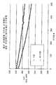
도 8은 20μ 다공성 분리막을 갖는 400mAh 프리즘형 10μ NCS 전지를 사용하여 자동차 산업에서 사용되는 전력 시험인 고펄스 전력 특성화 시험(HPPC)의 결과를 나타낸다. 상기 NCS 데이타는 그래프 상의 상부 라인으로 나타낸다. 상기 NCS 전지는 기준 폴리올레핀 분리막 전지보다 고전력 방전에서 더 많은 에너지를 보유하며, 이는 10μ NCS 층에 의해 형성된 총 분리막 두께의 추가의 10μ가 전력을 감소시키지 않음을 설명한다. 보다 얇은 다공성 분리막이 사용되는 경우, 상기 에너지/용적은 본 실시예에 비해 더 높다. 이러한 시험을 위해, 상기 NCS를 상기 캐소드 위에 배치되며, 10㎛ 두께의 분리막 두께를 갖고, 상술한 65:35 제형을 사용하였다.FIG. 8 shows the results of the High Pulse Power Characterization Test (HPPC), a power test used in the automotive industry using a 400 mAh prismatic 10 μ NCS cell with a 20 μ porous separator. The NCS data is represented by the top line on the graph. The NCS cell retains more energy at high power discharges than the reference polyolefin separator cell, demonstrating that an additional 10 μ of the total separator thickness formed by the 10 μ NCS layer does not reduce power. When thinner porous separators are used, the energy / volume is higher than in this example. For this test, the NCS was placed above the cathode, had a separator thickness of 10 μm thick, and used the 65:35 formulation described above.
도 9는 NCS 층은 없지만 20μ 두께의 분리막은 있는 기준 배열에 대해 20㎛ 두께의 분리막을 갖는 65:35 제형을 갖는 세미-NCS 또는 "캐소드 세미"를 사용하는 실온 고전력 사이클 시험(1.5C/-10C)으로부터의 데이타를 플롯팅한 그래프이다. 상기 데이타는 세미-NCS와 기준 둘 다에 대해 2개의 전지의 평균을 나타낸다. 상기 세미-NCS 데이타는 그래프 상에 약간 낮은 라인으로 나타낸다. 상기 전지는 +1.5C/-10C에서 사이클링된다. 평균으로, 상기 세미-NCS 전지는 초기 용량의 80% 이하로 기준 전지에 비해 더 빨리 강하하지 않는다. 예를 들면, 상기 페이딩(fading)에 대해 동일한 기울기이다. 마찬가지로, DC 저항은 양쪽 전지에서 필적하는 것으로 밝혀졌다. 이는 사이클링 동안 고성능을 유지하면서 증가된 안전성 인자를 제공하는 본 발명의 능력을 나타낸다.9 is a room temperature high power cycle test (1.5 C / −) using a semi-NCS or “cathode semi” with a 65:35 formulation having a 20 μm thick separator for a reference array without an NCS layer but with a 20 μm separator. Graph plotting data from 10C). The data represent the average of two cells for both semi-NCS and reference. The semi-NCS data is shown as slightly lower lines on the graph. The cell is cycled at +1.5 C / -10 C. On average, the semi-NCS cell does not drop more quickly than the reference cell at 80% or less of its initial capacity. For example, the same slope for the fading. Similarly, DC resistance was found to be comparable in both cells. This represents the ability of the present invention to provide increased safety factors while maintaining high performance during cycling.
도 10은 NCS 층이 없는 기준 배열에 대해 65:35 NCS 제형 10μ 및 20μ 다공성 분리막을 갖는 세미-NCS 배열을 사용하는 실온 저전력 사이클링 시험(1.5C/-2.5C)으로부터의 데이타를 플롯팅한 그래프이다. 상기 데이타는 세미-NCS와 기준 둘 다에 대해 2개의 전지의 평균을 나타낸다. 상기 캐소드-NCS 데이타는 그래프 상에 약간 낮은 라인으로 나타낸다. 상기 전지는 +1.5C/-2.5C에서 사이클링된다. 상기 세미-NCS 전지는 기준 전지에 비해 대체로 더 빨리 페이딩되지만, 두 전지 모두 500사이클 후 초기 용량의 80%를 초과한다.FIG. 10 is a graph plotting data from room temperature low power cycling test (1.5C / -2.5C) using a semi-NCS array with 65:35 NCS formulations 10μ and 20μ porous separator for a reference arrangement without an NCS layer. to be. The data represent the average of two cells for both semi-NCS and reference. The cathode-NCS data is shown as slightly lower lines on the graph. The cell is cycled at +1.5 C / -2.5 C. The semi-NCS cell fades generally faster than the reference cell, but both cells exceed 80% of their initial capacity after 500 cycles.
위에서 본 발명의 예시 양태들을 설명하였다. 본 발명의 기타 개질 및 변형은 본원에 제공된 교시를 토대로 당업자에게 용이하게 이해될 것이다. 상기 기재는 설명을 위함이지 본 발명을 실행시 이를 제한할 의도는 없다. 본 발명의 범위를 한정하는 것은 후술되는 특허청구범위이며, 여기에는 모든 등가물이 포함된다. The illustrative aspects of the invention have been described above. Other modifications and variations of the present invention will be readily appreciated by those skilled in the art based on the teachings provided herein. The foregoing description is for illustrative purposes only and is not intended to be limiting upon practicing the invention. It is intended that the scope of the invention be limited to the claims appended hereto, including all equivalents.
Claims (39)
상기 전기화학전지는 (a) 양극, (b) 음극, (c) 상기 양극과 상기 음극 사이에 삽입된 다공성 무기 및 유기 복합 필름(여기서, 상기 복합 필름은 무기 나노입자와 결합제를 포함한다) 및 (d) 리튬염 및 비수성 용제를 포함하는 전해질을 포함하며,
(3) 상기 복합 필름에 인접한 다공성 또는 비다공성 분리막(separator)을 추가로 포함하고, 상기 복합 필름의 두께와 다공성 또는 비다공성 분리막의 두께의 합이 25㎛ 이하인 전기화학전지.Li-ion electrochemical cell,
The electrochemical cell includes (a) a positive electrode, (b) a negative electrode, (c) a porous inorganic and organic composite film inserted between the positive electrode and the negative electrode, wherein the composite film includes inorganic nanoparticles and a binder; and (d) an electrolyte comprising a lithium salt and a non-aqueous solvent,
(3) an electrochemical cell further comprising a porous or nonporous separator adjacent to the composite film, wherein the sum of the thickness of the composite film and the thickness of the porous or nonporous separator is 25 μm or less.
상기 집전체에 부착된, 적어도 전기활성 입자들과 결합제를 포함하는 전극층;
나노기공을 형성하기 위해 중합체 매트릭스 중에 실질적으로 균질하게 분포된 무기 입자들을 포함하는 다공성 복합층[여기서, 상기 복합층은 상기 전극층에 상기 두 층들 사이의 계면에서 용제 접착제(solvent weld)에 의해 고정되며, 상기 용제 접착제는 상기 결합제와 상기 중합체의 혼합물을 포함한다]; 및
상기 복합층에 인접하게 배치된 다공성 또는 비다공성 분리막을 포함하며,
상기 복합층의 두께와 상기 다공성 분리막의 두께의 합이 25㎛ 이하인, 전기화학전지용 전극/분리막 어셈블리.Current collector;
An electrode layer comprising at least electroactive particles and a binder attached to the current collector;
A porous composite layer comprising inorganic particles substantially homogeneously distributed in a polymer matrix to form nanopores, wherein the composite layer is fixed to the electrode layer by a solvent weld at the interface between the two layers. Wherein said solvent adhesive comprises a mixture of said binder and said polymer; And
It comprises a porous or nonporous separator disposed adjacent to the composite layer,
The sum of the thickness of the composite layer and the thickness of the porous separator is 25㎛ or less, electrochemical cell electrode / separator assembly.
피복 용액(여기서, 상기 피복 용액은 중합체, 상기 중합체용 용제 시스템, 및 상기 용제에 분산된 무기 입자를 포함하며, 여기서 상기 용제 시스템은 전극층의 결합제에 대해 적어도 어느 정도의 용해도를 갖도록 선택된다)을 제공하는 단계;
상기 전극층의 표면을 상기 피복 용액 층(여기서, 상기 피복 용액은 상기 전극층의 두께의 일정 분율에 침투하여 상기 결합제의 일부를 용해시킨다)으로 피복하는 단계;
상기 용제를 상기 피복 용액 층으로부터 제거하여 중합체 중에 실질적으로 균질하게 분포된 무기 입자들을 포함하는 다공성 복합층을 침착시키고 상기 다공성 전극층과 상기 다공성 분리막 사이의 계면에 용제 접착제를 형성시키는 단계; 및
상기 다공성 복합층에 인접하게 다공성 또는 비다공성 분리막을 제공하는 단계를 포함하며,
상기 복합 필름과 다공성 분리막이 이들의 두께의 합이 25㎛ 이하이도록 제공되고, 상기 피복 용액 중의 무기 입자들과 중합체의 중량 비가 약 95:5 내지 40:60인, 전기화학전지용 전극/분리막 어셈블리의 제조방법.Providing an electrode layer comprising at least electroactive particles and a binder;
Coating solution, wherein the coating solution comprises a polymer, the solvent system for the polymer, and inorganic particles dispersed in the solvent, wherein the solvent system is selected to have at least some degree of solubility in the binder of the electrode layer. Providing;
Coating the surface of the electrode layer with the coating solution layer, wherein the coating solution infiltrates a fraction of the thickness of the electrode layer to dissolve a portion of the binder;
Removing the solvent from the coating solution layer to deposit a porous composite layer comprising inorganic particles substantially homogeneously distributed in a polymer and forming a solvent adhesive at an interface between the porous electrode layer and the porous separator; And
Providing a porous or nonporous separator adjacent to the porous composite layer,
The composite film and the porous separator are provided so that the sum of the thickness thereof is 25 μm or less, and the weight ratio of the inorganic particles and the polymer in the coating solution is about 95: 5 to 40:60. Manufacturing method.
Applications Claiming Priority (2)
| Application Number | Priority Date | Filing Date | Title |
|---|---|---|---|
| US99577707P | 2007-09-28 | 2007-09-28 | |
| US60/995,777 | 2007-09-28 |
Publications (1)
| Publication Number | Publication Date |
|---|---|
| KR20100098498A true KR20100098498A (en) | 2010-09-07 |
Family
ID=40508750
Family Applications (1)
| Application Number | Title | Priority Date | Filing Date |
|---|---|---|---|
| KR1020107009415A KR20100098498A (en) | 2007-09-28 | 2008-09-29 | Batteries having inorganic/organic porous films |
Country Status (7)
| Country | Link |
|---|---|
| US (1) | US8852787B2 (en) |
| EP (1) | EP2193569B1 (en) |
| JP (1) | JP5591704B2 (en) |
| KR (1) | KR20100098498A (en) |
| CN (1) | CN101809801B (en) |
| TW (1) | TW200931702A (en) |
| WO (1) | WO2009043011A1 (en) |
Cited By (5)
| Publication number | Priority date | Publication date | Assignee | Title |
|---|---|---|---|---|
| KR20140048197A (en) * | 2011-07-11 | 2014-04-23 | 캘리포니아 인스티튜트 오브 테크놀로지 | Novel separators for electrochemical systems |
| KR20170105283A (en) * | 2016-03-09 | 2017-09-19 | 삼성에스디아이 주식회사 | Secondary battery |
| US10155361B2 (en) | 2011-11-09 | 2018-12-18 | Corning Incorporated | Method of binding nanoparticles to glass |
| US10714724B2 (en) | 2013-11-18 | 2020-07-14 | California Institute Of Technology | Membranes for electrochemical cells |
| US11527802B2 (en) | 2011-07-11 | 2022-12-13 | California Institute Of Technology | Electrochemical systems with ionically conductive and electronically insulating separator |
Families Citing this family (59)
| Publication number | Priority date | Publication date | Assignee | Title |
|---|---|---|---|---|
| US8883354B2 (en) | 2006-02-15 | 2014-11-11 | Optodot Corporation | Separators for electrochemical cells |
| US11084311B2 (en) | 2008-02-29 | 2021-08-10 | Illinois Tool Works Inc. | Receiver material having a polymer with nano-composite filler material |
| DE102008046498A1 (en) * | 2008-09-10 | 2010-03-11 | Li-Tec Battery Gmbh | Electrode and separator material for lithium-ion cells and process for their preparation |
| DE112010000853T5 (en) * | 2009-01-12 | 2012-12-06 | A123 Systems, Inc. | Laminated battery cell and method for its production |
| KR101943647B1 (en) * | 2009-02-23 | 2019-01-29 | 가부시키가이샤 무라타 세이사쿠쇼 | Nonaqueous electrolyte composition, nonaqueous electrolyte secondary battery, and method for manufacturing nonaqueous electrolyte secondary battery |
| WO2010134170A1 (en) * | 2009-05-20 | 2010-11-25 | Necトーキン株式会社 | Laminated secondary battery, and method for manufacturing the laminated secondary battery |
| KR20170045366A (en) | 2009-05-26 | 2017-04-26 | 옵토도트 코포레이션 | Batteries utilizing anode coating directly on nanoporous separators |
| CN101938013B (en) * | 2009-06-30 | 2014-07-02 | 比亚迪股份有限公司 | Polymer electrolyte and preparation method thereof and polymer lithium secondary battery |
| DE102009035490A1 (en) * | 2009-07-31 | 2011-02-03 | Daimler Ag | Electrode arrangement for a single battery cell |
| US20130183568A1 (en) * | 2009-11-18 | 2013-07-18 | Susan J. Babinec | Composite separator for electrochemical cell and method for its manufacture |
| US20110183203A1 (en) * | 2010-01-27 | 2011-07-28 | Molecular Nanosystems, Inc. | Polymer supported electrodes |
| JP2011159488A (en) * | 2010-02-01 | 2011-08-18 | Sony Corp | Nonaqueous electrolyte composition, and nonaqueous electrolyte secondary battery |
| JP5990804B2 (en) | 2010-07-19 | 2016-09-14 | オプトドット コーポレイション | Electrochemical battery separator |
| CN103168384B (en) | 2010-09-30 | 2015-11-25 | 应用材料公司 | The integration separator of Electrospun lithium ion battery |
| DE102010048919A1 (en) | 2010-10-07 | 2012-04-12 | Schott Ag | Electrochemical energy storage and use of a glass-based material for producing a separator for such |
| JP2013539190A (en) | 2010-10-07 | 2013-10-17 | ショット アクチエンゲゼルシャフト | Glass-based materials for manufacturing separators used in electrochemical energy batteries |
| DE102010048922A1 (en) | 2010-10-07 | 2012-04-12 | Schott Ag | Use of material based on glass, comprising mixture of silicon dioxide, fluorine and phosphorus pentoxide, and aluminum oxide, useful for producing separator for electrochemical energy storage, preferably for lithium ion accumulator |
| JP5618165B2 (en) * | 2010-11-26 | 2014-11-05 | トヨタ自動車株式会社 | Nonaqueous electrolyte secondary battery |
| DE102011114876A1 (en) | 2011-09-29 | 2013-04-04 | Schott Ag | Rechargeable lithium-ion battery and use of a glass-based material therefor |
| CN102501524A (en) * | 2011-11-03 | 2012-06-20 | 南京大学 | Diaphragm with uniform pore size-adjustable composite structure and preparation method thereof |
| JP6251680B2 (en) | 2011-11-11 | 2017-12-20 | エルジー・ケム・リミテッド | Separator and electrochemical device including the same |
| KR101904160B1 (en) | 2012-02-08 | 2018-10-05 | 에스케이이노베이션 주식회사 | micro-porous hybrid polyolefin film having excellent thermal property and stability and manufacturing method thereof |
| JP2016517161A (en) | 2013-04-29 | 2016-06-09 | マディコ インコーポレイテッド | Nanoporous composite separator with enhanced thermal conductivity |
| KR101736013B1 (en) * | 2013-07-03 | 2017-05-24 | 시온 파워 코퍼레이션 | Ceramic/polymer matrix for electrode protection in electrochemical cells, including rechargeable lithium batteries |
| US9412986B2 (en) * | 2013-07-31 | 2016-08-09 | GM Global Technology Operations LLC | Porous composite structures for lithium-ion battery separators |
| DE102013218499A1 (en) * | 2013-09-16 | 2015-03-19 | Robert Bosch Gmbh | Separator of a lithium battery cell and lithium battery |
| JP6219113B2 (en) * | 2013-09-30 | 2017-10-25 | 株式会社東芝 | Secondary battery |
| CN103515563A (en) * | 2013-10-15 | 2014-01-15 | 杨海燕 | Method for manufacturing ceramic diaphragm for high-safety lithium ion battery |
| WO2015074065A1 (en) | 2013-11-18 | 2015-05-21 | California Institute Of Technology | Electrochemical separators with inserted conductive layers |
| US10490796B2 (en) | 2014-02-19 | 2019-11-26 | Sion Power Corporation | Electrode protection using electrolyte-inhibiting ion conductor |
| KR102316170B1 (en) | 2014-02-19 | 2021-10-21 | 시온 파워 코퍼레이션 | Electrode protection using a composite comprising an electrolyte-inhibiting ion conductor |
| KR101962418B1 (en) * | 2014-06-24 | 2019-03-27 | 제일모직 주식회사 | Separator, manufacturing the separator and battery using thereof |
| US10381623B2 (en) | 2015-07-09 | 2019-08-13 | Optodot Corporation | Nanoporous separators for batteries and related manufacturing methods |
| US11296361B2 (en) | 2015-07-07 | 2022-04-05 | Apple Inc. | Bipolar battery design |
| WO2017096258A1 (en) | 2015-12-02 | 2017-06-08 | California Institute Of Technology | Three-dimensional ion transport networks and current collectors for electrochemical cells |
| CN112366422A (en) * | 2016-03-29 | 2021-02-12 | 浙江地坤键新能源科技有限公司 | Non-porous diaphragm and application thereof |
| US11456456B2 (en) | 2016-06-23 | 2022-09-27 | United States Of America As Represented By The Secretary Of The Air Force | Bendable, creasable, and printable batteries with enhanced safety and high temperature stability—methods of fabrication, and methods of using the same |
| CN117638425A (en) | 2016-09-22 | 2024-03-01 | 苹果公司 | Current collector for stacked cell design |
| US20180104921A1 (en) * | 2016-10-17 | 2018-04-19 | Johnson & Johnson Vision Care, Inc. | Biomedical device batteries with electrodeposited cathodes |
| WO2018180017A1 (en) * | 2017-03-31 | 2018-10-04 | Necエナジーデバイス株式会社 | Battery electrode and lithium ion secondary battery |
| WO2018195372A1 (en) * | 2017-04-21 | 2018-10-25 | Cougeller Research Llc | Battery cell with electrolyte diffusion material |
| US11888112B2 (en) | 2017-05-19 | 2024-01-30 | Apple Inc. | Rechargeable battery with anion conducting polymer |
| US11018343B1 (en) | 2017-06-01 | 2021-05-25 | Apple Inc. | Current collector surface treatment |
| US10923728B1 (en) | 2017-06-16 | 2021-02-16 | Apple Inc. | Current collector structures for rechargeable battery |
| US10916741B1 (en) | 2017-08-08 | 2021-02-09 | Apple Inc. | Metallized current collector devices and materials |
| US11189834B1 (en) | 2017-08-09 | 2021-11-30 | Apple Inc. | Multiple electrolyte battery cells |
| US11862801B1 (en) | 2017-09-14 | 2024-01-02 | Apple Inc. | Metallized current collector for stacked battery |
| JP6783735B2 (en) * | 2017-09-19 | 2020-11-11 | 株式会社東芝 | Electrodes for lithium-ion secondary batteries, secondary batteries, battery packs and vehicles |
| US11335977B1 (en) | 2017-09-21 | 2022-05-17 | Apple Inc. | Inter-cell connection materials |
| US11043703B1 (en) | 2017-09-28 | 2021-06-22 | Apple Inc. | Stacked battery components and configurations |
| US10916796B1 (en) | 2018-02-02 | 2021-02-09 | Apple Inc. | Selective charging matrix for rechargeable batteries |
| CN108878748A (en) * | 2018-06-25 | 2018-11-23 | 宁德新能源科技有限公司 | Electrochemical appliance |
| CN109830630A (en) * | 2018-12-29 | 2019-05-31 | 深圳中兴新材技术股份有限公司 | Coating diaphragm with hierarchical porous structure and its preparation method and application |
| US20210005927A1 (en) * | 2019-07-01 | 2021-01-07 | A123 Systems Llc | Systems and methods for a composite solid-state battery cell with an ionically conductive polymer electrolyte |
| CN111430782B (en) * | 2020-05-08 | 2021-11-12 | 深圳市元鼎智能创新有限公司 | Silicon aerogel modified lithium ion battery diaphragm and preparation method thereof |
| US11588155B1 (en) | 2020-09-08 | 2023-02-21 | Apple Inc. | Battery configurations for cell balancing |
| US11600891B1 (en) | 2020-09-08 | 2023-03-07 | Apple Inc. | Battery configurations having balanced current collectors |
| US11677120B2 (en) | 2020-09-08 | 2023-06-13 | Apple Inc. | Battery configurations having through-pack fasteners |
| US11923494B2 (en) | 2020-09-08 | 2024-03-05 | Apple Inc. | Battery configurations having through-pack fasteners |
Family Cites Families (70)
| Publication number | Priority date | Publication date | Assignee | Title |
|---|---|---|---|---|
| US3861963A (en) | 1968-02-23 | 1975-01-21 | Mc Donnell Douglas Corp | Battery separator construction |
| US4224393A (en) | 1979-05-10 | 1980-09-23 | W. R. Grace & Co. | Battery separator |
| US5641565A (en) | 1991-07-05 | 1997-06-24 | Asahi Kasei Kogyo Kabushiki Kaisha | Separator for a battery using an organic electrolytic solution and method for preparing the same |
| US5194341A (en) | 1991-12-03 | 1993-03-16 | Bell Communications Research, Inc. | Silica electrolyte element for secondary lithium battery |
| WO1994020995A2 (en) | 1993-03-01 | 1994-09-15 | W.R. Grace & Co.-Conn. | Battery separators |
| US5418091A (en) | 1993-03-05 | 1995-05-23 | Bell Communications Research, Inc. | Polymeric electrolytic cell separator membrane |
| KR100242363B1 (en) | 1994-05-12 | 2000-02-01 | 나카히로 마오미 | Porous multi-layer film |
| DE19526476A1 (en) | 1995-07-20 | 1997-01-23 | Degussa | precipitated silica |
| US5643695A (en) | 1995-09-26 | 1997-07-01 | Valence Technology, Inc. | Carbonaceous electrode and compatible electrolyte |
| CN1115295C (en) | 1996-05-31 | 2003-07-23 | Ppg工业俄亥俄公司 | Amorphous precipitated silica |
| US5948464A (en) | 1996-06-19 | 1999-09-07 | Imra America, Inc. | Process of manufacturing porous separator for electrochemical power supply |
| US6447951B1 (en) | 1996-09-23 | 2002-09-10 | Valence Technology, Inc. | Lithium based phosphates, method of preparation, and uses thereof |
| US5720780A (en) | 1996-11-04 | 1998-02-24 | Valence Technology, Inc. | Film forming method for lithium ion rechargeable batteries |
| JP3303694B2 (en) | 1996-12-17 | 2002-07-22 | 三菱電機株式会社 | Lithium ion secondary battery and method of manufacturing the same |
| JP4491075B2 (en) | 1997-01-16 | 2010-06-30 | 三菱製紙株式会社 | Non-aqueous electrolyte battery separator, non-aqueous electrolyte battery using the same, and method for producing separator for non-aqueous electrolyte battery |
| US5894656A (en) | 1997-04-11 | 1999-04-20 | Valence Technology, Inc. | Methods of fabricating electrochemical cells |
| US5882721A (en) | 1997-05-01 | 1999-03-16 | Imra America Inc | Process of manufacturing porous separator for electrochemical power supply |
| US6821672B2 (en) | 1997-09-02 | 2004-11-23 | Kvg Technologies, Inc. | Mat of glass and other fibers and method for producing it |
| US6180281B1 (en) | 1997-12-12 | 2001-01-30 | Johnson Research & Development Company, Inc. | Composite separator and electrode |
| US6153337A (en) | 1997-12-19 | 2000-11-28 | Moltech Corporation | Separators for electrochemical cells |
| US6235065B1 (en) | 1998-10-27 | 2001-05-22 | Alcatel | Room temperature lamination of Li-ion polymer electrodes |
| US6277514B1 (en) * | 1998-12-17 | 2001-08-21 | Moltech Corporation | Protective coating for separators for electrochemical cells |
| US6194098B1 (en) | 1998-12-17 | 2001-02-27 | Moltech Corporation | Protective coating for separators for electrochemical cells |
| US6077468A (en) | 1999-01-11 | 2000-06-20 | 3M Innovative Properties Company | Process of drawing fibers |
| US6148503A (en) | 1999-03-31 | 2000-11-21 | Imra America, Inc. | Process of manufacturing porous separator for electrochemical power supply |
| DE19918109A1 (en) | 1999-04-22 | 2000-10-26 | Nbt Gmbh | Process for the production of a secondary lithium cell with a heat-sensitive protective mechanism |
| US6680144B2 (en) | 1999-10-29 | 2004-01-20 | Kvg Technologies, Inc. | Battery separator |
| KR20020086858A (en) | 1999-12-09 | 2002-11-20 | 엔티케이 파워덱스 인코포레이티드 | Battery separator for li-ion and/or li-ion polymer battery |
| US6528033B1 (en) | 2000-01-18 | 2003-03-04 | Valence Technology, Inc. | Method of making lithium-containing materials |
| US6432586B1 (en) * | 2000-04-10 | 2002-08-13 | Celgard Inc. | Separator for a high energy rechargeable lithium battery |
| US6777132B2 (en) | 2000-04-27 | 2004-08-17 | Valence Technology, Inc. | Alkali/transition metal halo—and hydroxy-phosphates and related electrode active materials |
| CN1193448C (en) * | 2000-06-07 | 2005-03-16 | 三洋杰士电池有限公司 | Battery |
| DE10112441A1 (en) | 2001-03-15 | 2002-09-19 | Degussa | Silica by precipitation with a constant alkali number and its use |
| US6727017B1 (en) | 2001-04-06 | 2004-04-27 | Changs Ascending Enterprise Co., Ltd. | Methods of fabricating binding layers for a Li-ion polymer battery |
| DE10142622A1 (en) | 2001-08-31 | 2003-03-20 | Creavis Tech & Innovation Gmbh | Electrical separator, process for its production and use |
| DE10208277A1 (en) | 2002-02-26 | 2003-09-04 | Creavis Tech & Innovation Gmbh | Electrical separator, process for its production and use |
| ATE315537T1 (en) | 2002-06-14 | 2006-02-15 | Degussa | ALUMINUM-CONTAINING PRECIPITATED SILICIC ACID WITH ADJUSTABLE BET/CTAB RATIO |
| US6913855B2 (en) | 2002-07-22 | 2005-07-05 | Valence Technology, Inc. | Method of synthesizing electrochemically active materials from a slurry of precursors |
| US7008724B2 (en) | 2002-07-24 | 2006-03-07 | Enerdel, Inc. | Lithium cell with mixed polymer system |
| DE10238944A1 (en) | 2002-08-24 | 2004-03-04 | Creavis Gesellschaft Für Technologie Und Innovation Mbh | Separator for use in high energy batteries and process for its manufacture |
| DE10238941B4 (en) | 2002-08-24 | 2013-03-28 | Evonik Degussa Gmbh | Electric separator, process for its manufacture and use in lithium high-performance batteries and a battery having the separator |
| DE10240032A1 (en) | 2002-08-27 | 2004-03-11 | Creavis Gesellschaft Für Technologie Und Innovation Mbh | Ion-conducting battery separator for lithium batteries, process for their production and their use |
| KR100573358B1 (en) * | 2002-09-17 | 2006-04-24 | 가부시키가이샤 도모에가와 세이시쇼 | Separator for lithium-ion secondary battery and lithium-ion secondary battery comprising the same |
| DE10255121B4 (en) | 2002-11-26 | 2017-09-14 | Evonik Degussa Gmbh | Separator with asymmetric pore structure for an electrochemical cell |
| DE10255122A1 (en) | 2002-11-26 | 2004-06-03 | Creavis Gesellschaft Für Technologie Und Innovation Mbh | Long-term stable separator for an electrochemical cell |
| MXPA05007589A (en) | 2003-01-22 | 2005-09-30 | Degussa | Specially precipitated silicic acids for rubber applications. |
| US7115339B2 (en) | 2003-02-21 | 2006-10-03 | Matsushita Electric Industrial Co., Ltd. | Lithium ion secondary battery |
| US6967828B2 (en) * | 2003-05-30 | 2005-11-22 | Medtronic, Inc. | Capacitors including metalized separators |
| US7901810B2 (en) | 2003-06-03 | 2011-03-08 | Valence Technology, Inc. | Battery active materials and methods for synthesis |
| DE10347567A1 (en) | 2003-10-14 | 2005-05-12 | Degussa | Electric separator with shut-off mechanism, process for its manufacture and use in lithium batteries |
| JP3953022B2 (en) | 2003-10-29 | 2007-08-01 | 松下電器産業株式会社 | Lithium ion secondary battery and method of configuring the same |
| KR100699215B1 (en) | 2004-03-19 | 2007-03-27 | 가부시키가이샤 도모에가와 세이시쇼 | Separator for electric component and method for producing the same |
| KR100790280B1 (en) * | 2004-03-30 | 2008-01-02 | 마쯔시다덴기산교 가부시키가이샤 | Nonaqueous electrolyte secondary battery |
| JP4649862B2 (en) * | 2004-04-02 | 2011-03-16 | パナソニック株式会社 | Lithium ion secondary battery and manufacturing method thereof |
| JP4763253B2 (en) * | 2004-05-17 | 2011-08-31 | パナソニック株式会社 | Lithium ion secondary battery |
| KR100802870B1 (en) | 2004-05-27 | 2008-02-13 | 마쯔시다덴기산교 가부시키가이샤 | Wound nonaqueous secondary battery and electrode plate used therein |
| CN100452487C (en) | 2004-06-22 | 2009-01-14 | 松下电器产业株式会社 | Secondary battery and method for producing the same |
| KR100749301B1 (en) * | 2004-07-07 | 2007-08-14 | 주식회사 엘지화학 | New organic/inorganic composite porous film and electrochemical device prepared thereby |
| HUE052954T2 (en) * | 2004-07-07 | 2021-05-28 | Lg Chemical Ltd | Organic/inorganic composite porous separator and electrochemical device comprasing the same. |
| US20060292450A1 (en) | 2004-07-13 | 2006-12-28 | Matsushita Electric Industrial Co., Ltd. | Non-aqueous electrolyte secondary battery |
| KR100742959B1 (en) * | 2004-09-02 | 2007-07-25 | 주식회사 엘지화학 | Organic/inorganic composite porous film and electrochemical device using the same |
| EP1784876B1 (en) | 2004-09-02 | 2018-01-24 | LG Chem, Ltd. | Organic/inorganic composite porous film and electrochemical device prepared thereby |
| KR101146870B1 (en) | 2004-10-21 | 2012-05-16 | 에보니크 데구사 게엠베하 | Inorganic separator-electrode-unit for lithium-ion batteries, method for the production thereof and use thereof in lithium batteries |
| KR100659820B1 (en) | 2004-11-17 | 2006-12-19 | 삼성에스디아이 주식회사 | Lithium ion secondary battery |
| KR100775310B1 (en) | 2004-12-22 | 2007-11-08 | 주식회사 엘지화학 | Organic/inorganic composite microporous membrane and electrochemical device prepared thereby |
| JP4776918B2 (en) * | 2004-12-24 | 2011-09-21 | 日立マクセルエナジー株式会社 | Non-aqueous electrolyte secondary battery |
| KR20070008024A (en) | 2005-07-12 | 2007-01-17 | 삼성전자주식회사 | Cmos device and method of manufacturing the same |
| TWI330136B (en) | 2005-11-28 | 2010-09-11 | Lg Chemical Ltd | Organic/inorganic composite porous membrane and electrochemical device using the same |
| JP5426551B2 (en) * | 2007-08-21 | 2014-02-26 | エー123 システムズ, インコーポレイテッド | Electrochemical cell separator and method for producing the same |
| DE112010000853T5 (en) | 2009-01-12 | 2012-12-06 | A123 Systems, Inc. | Laminated battery cell and method for its production |
-
2008
- 2008-09-29 CN CN200880109165.5A patent/CN101809801B/en active Active
- 2008-09-29 US US12/240,855 patent/US8852787B2/en active Active
- 2008-09-29 JP JP2010527240A patent/JP5591704B2/en active Active
- 2008-09-29 WO PCT/US2008/078133 patent/WO2009043011A1/en active Application Filing
- 2008-09-29 KR KR1020107009415A patent/KR20100098498A/en not_active Application Discontinuation
- 2008-09-29 EP EP08833067.5A patent/EP2193569B1/en not_active Not-in-force
- 2008-09-30 TW TW097137609A patent/TW200931702A/en unknown
Cited By (5)
| Publication number | Priority date | Publication date | Assignee | Title |
|---|---|---|---|---|
| KR20140048197A (en) * | 2011-07-11 | 2014-04-23 | 캘리포니아 인스티튜트 오브 테크놀로지 | Novel separators for electrochemical systems |
| US11527802B2 (en) | 2011-07-11 | 2022-12-13 | California Institute Of Technology | Electrochemical systems with ionically conductive and electronically insulating separator |
| US10155361B2 (en) | 2011-11-09 | 2018-12-18 | Corning Incorporated | Method of binding nanoparticles to glass |
| US10714724B2 (en) | 2013-11-18 | 2020-07-14 | California Institute Of Technology | Membranes for electrochemical cells |
| KR20170105283A (en) * | 2016-03-09 | 2017-09-19 | 삼성에스디아이 주식회사 | Secondary battery |
Also Published As
| Publication number | Publication date |
|---|---|
| EP2193569A4 (en) | 2011-10-19 |
| JP2011518404A (en) | 2011-06-23 |
| EP2193569B1 (en) | 2015-04-08 |
| CN101809801B (en) | 2014-03-26 |
| CN101809801A (en) | 2010-08-18 |
| EP2193569A1 (en) | 2010-06-09 |
| US8852787B2 (en) | 2014-10-07 |
| WO2009043011A1 (en) | 2009-04-02 |
| TW200931702A (en) | 2009-07-16 |
| JP5591704B2 (en) | 2014-09-17 |
| US20090087728A1 (en) | 2009-04-02 |
Similar Documents
| Publication | Publication Date | Title |
|---|---|---|
| KR20100098498A (en) | Batteries having inorganic/organic porous films | |
| EP3444866B1 (en) | Separator and electrochemical device including the same | |
| US10497916B2 (en) | Separator for electrochemical cell and method for its manufacture | |
| JP6092389B2 (en) | Organic / inorganic composite coating porous separation membrane and secondary battery element using the same | |
| US8697290B2 (en) | Laminated battery cell comprising multilayer composite separator and methods for creating the same | |
| TWI422090B (en) | Organic/inorganic composite separator having morphology gradient, and manufacturing method thereof and electrochemical device containing the same | |
| JP6148331B2 (en) | Method for producing porous / separated porous membrane for lithium secondary battery using aqueous coating solution | |
| TWI464937B (en) | Organic/inorganic composite separator having porous active coating layer and electrochemical device containing the same | |
| TWI557169B (en) | Organic/inorganic composite porous membrane, and separator and electrode structure comprising the same | |
| EP3734700A1 (en) | Separator and electrochemical device comprising same | |
| EP3365931B1 (en) | Coated battery separator | |
| CN115088128A (en) | Separator for lithium secondary battery and method of manufacturing the same | |
| JP2023524003A (en) | Separation membrane for lithium secondary battery, method for producing the same, and separation membrane produced thereby | |
| JP2024503458A (en) | Separators and electrochemical devices containing them |
Legal Events
| Date | Code | Title | Description |
|---|---|---|---|
| A201 | Request for examination | ||
| E902 | Notification of reason for refusal | ||
| E601 | Decision to refuse application |