KR20100092481A - Multi-angle pop-in mechanical fastener - Google Patents
Multi-angle pop-in mechanical fastener Download PDFInfo
- Publication number
- KR20100092481A KR20100092481A KR1020107012750A KR20107012750A KR20100092481A KR 20100092481 A KR20100092481 A KR 20100092481A KR 1020107012750 A KR1020107012750 A KR 1020107012750A KR 20107012750 A KR20107012750 A KR 20107012750A KR 20100092481 A KR20100092481 A KR 20100092481A
- Authority
- KR
- South Korea
- Prior art keywords
- mechanical fastener
- angle
- pop
- locking
- base
- Prior art date
Links
- 238000003780 insertion Methods 0.000 claims description 101
- 230000037431 insertion Effects 0.000 claims description 101
- 230000013011 mating Effects 0.000 claims description 23
- 238000000034 method Methods 0.000 claims description 5
- 238000003825 pressing Methods 0.000 claims description 3
- 238000013461 design Methods 0.000 description 15
- 239000000853 adhesive Substances 0.000 description 9
- 230000001070 adhesive effect Effects 0.000 description 9
- -1 polypropylene Polymers 0.000 description 7
- 238000012360 testing method Methods 0.000 description 7
- 229920005989 resin Polymers 0.000 description 6
- 239000011347 resin Substances 0.000 description 6
- 238000000926 separation method Methods 0.000 description 6
- 239000004743 Polypropylene Substances 0.000 description 5
- 230000000875 corresponding effect Effects 0.000 description 5
- 230000007423 decrease Effects 0.000 description 5
- 230000003993 interaction Effects 0.000 description 5
- 229920001155 polypropylene Polymers 0.000 description 5
- 230000009977 dual effect Effects 0.000 description 3
- 238000002347 injection Methods 0.000 description 3
- 239000007924 injection Substances 0.000 description 3
- 238000005304 joining Methods 0.000 description 3
- 239000000463 material Substances 0.000 description 3
- 229920000728 polyester Polymers 0.000 description 3
- 238000010998 test method Methods 0.000 description 3
- 239000004593 Epoxy Substances 0.000 description 2
- 230000000295 complement effect Effects 0.000 description 2
- 238000000605 extraction Methods 0.000 description 2
- 238000001746 injection moulding Methods 0.000 description 2
- 229920000642 polymer Polymers 0.000 description 2
- 229920000098 polyolefin Polymers 0.000 description 2
- 229920001169 thermoplastic Polymers 0.000 description 2
- 235000001674 Agaricus brunnescens Nutrition 0.000 description 1
- 239000004831 Hot glue Substances 0.000 description 1
- 229920003171 Poly (ethylene oxide) Polymers 0.000 description 1
- 239000004952 Polyamide Substances 0.000 description 1
- 239000004698 Polyethylene Substances 0.000 description 1
- 239000004721 Polyphenylene oxide Substances 0.000 description 1
- 239000004820 Pressure-sensitive adhesive Substances 0.000 description 1
- 239000004433 Thermoplastic polyurethane Substances 0.000 description 1
- 229920000122 acrylonitrile butadiene styrene Polymers 0.000 description 1
- 239000000956 alloy Substances 0.000 description 1
- 229910045601 alloy Inorganic materials 0.000 description 1
- 230000004075 alteration Effects 0.000 description 1
- 229920006020 amorphous polyamide Polymers 0.000 description 1
- 125000003118 aryl group Chemical group 0.000 description 1
- 229920005601 base polymer Polymers 0.000 description 1
- 238000005452 bending Methods 0.000 description 1
- 230000015572 biosynthetic process Effects 0.000 description 1
- 125000004432 carbon atom Chemical group C* 0.000 description 1
- 229920002301 cellulose acetate Polymers 0.000 description 1
- 230000008859 change Effects 0.000 description 1
- 229920006018 co-polyamide Polymers 0.000 description 1
- 230000006835 compression Effects 0.000 description 1
- 238000007906 compression Methods 0.000 description 1
- 239000012141 concentrate Substances 0.000 description 1
- 229920001577 copolymer Polymers 0.000 description 1
- 230000002596 correlated effect Effects 0.000 description 1
- 230000008878 coupling Effects 0.000 description 1
- 238000010168 coupling process Methods 0.000 description 1
- 238000005859 coupling reaction Methods 0.000 description 1
- 230000006378 damage Effects 0.000 description 1
- 230000003247 decreasing effect Effects 0.000 description 1
- 230000007812 deficiency Effects 0.000 description 1
- 230000001419 dependent effect Effects 0.000 description 1
- 238000009826 distribution Methods 0.000 description 1
- 229920001971 elastomer Polymers 0.000 description 1
- 239000000806 elastomer Substances 0.000 description 1
- 229920005648 ethylene methacrylic acid copolymer Polymers 0.000 description 1
- 230000001747 exhibiting effect Effects 0.000 description 1
- 238000001125 extrusion Methods 0.000 description 1
- 239000012634 fragment Substances 0.000 description 1
- 229920001519 homopolymer Polymers 0.000 description 1
- 229920000554 ionomer Polymers 0.000 description 1
- 238000010030 laminating Methods 0.000 description 1
- 238000004519 manufacturing process Methods 0.000 description 1
- 238000005259 measurement Methods 0.000 description 1
- 239000002184 metal Substances 0.000 description 1
- 238000012986 modification Methods 0.000 description 1
- 230000004048 modification Effects 0.000 description 1
- 239000000178 monomer Substances 0.000 description 1
- 238000000465 moulding Methods 0.000 description 1
- 229920001778 nylon Polymers 0.000 description 1
- 229920000233 poly(alkylene oxides) Polymers 0.000 description 1
- 229920002239 polyacrylonitrile Polymers 0.000 description 1
- 229920002647 polyamide Polymers 0.000 description 1
- 239000004417 polycarbonate Substances 0.000 description 1
- 229920000515 polycarbonate Polymers 0.000 description 1
- 229920000573 polyethylene Polymers 0.000 description 1
- 239000002952 polymeric resin Substances 0.000 description 1
- 229920006380 polyphenylene oxide Polymers 0.000 description 1
- 229920001451 polypropylene glycol Polymers 0.000 description 1
- 239000004800 polyvinyl chloride Substances 0.000 description 1
- 229920000915 polyvinyl chloride Polymers 0.000 description 1
- 230000008569 process Effects 0.000 description 1
- 230000005855 radiation Effects 0.000 description 1
- 238000011084 recovery Methods 0.000 description 1
- 150000003839 salts Chemical class 0.000 description 1
- 229920006126 semicrystalline polymer Polymers 0.000 description 1
- 229920002725 thermoplastic elastomer Polymers 0.000 description 1
- 229920002803 thermoplastic polyurethane Polymers 0.000 description 1
- 229920005992 thermoplastic resin Polymers 0.000 description 1
- 229920001187 thermosetting polymer Polymers 0.000 description 1
- 239000004416 thermosoftening plastic Substances 0.000 description 1
- 230000007704 transition Effects 0.000 description 1
- 238000003466 welding Methods 0.000 description 1
Images


Classifications
-
- F—MECHANICAL ENGINEERING; LIGHTING; HEATING; WEAPONS; BLASTING
- F16—ENGINEERING ELEMENTS AND UNITS; GENERAL MEASURES FOR PRODUCING AND MAINTAINING EFFECTIVE FUNCTIONING OF MACHINES OR INSTALLATIONS; THERMAL INSULATION IN GENERAL
- F16B—DEVICES FOR FASTENING OR SECURING CONSTRUCTIONAL ELEMENTS OR MACHINE PARTS TOGETHER, e.g. NAILS, BOLTS, CIRCLIPS, CLAMPS, CLIPS OR WEDGES; JOINTS OR JOINTING
- F16B21/00—Means for preventing relative axial movement of a pin, spigot, shaft or the like and a member surrounding it; Stud-and-socket releasable fastenings
- F16B21/06—Releasable fastening devices with snap-action
- F16B21/08—Releasable fastening devices with snap-action in which the stud, pin, or spigot has a resilient part
- F16B21/086—Releasable fastening devices with snap-action in which the stud, pin, or spigot has a resilient part the shank of the stud, pin or spigot having elevations, ribs, fins or prongs intended for deformation or tilting predominantly in a direction perpendicular to the direction of insertion
-
- F—MECHANICAL ENGINEERING; LIGHTING; HEATING; WEAPONS; BLASTING
- F16—ENGINEERING ELEMENTS AND UNITS; GENERAL MEASURES FOR PRODUCING AND MAINTAINING EFFECTIVE FUNCTIONING OF MACHINES OR INSTALLATIONS; THERMAL INSULATION IN GENERAL
- F16B—DEVICES FOR FASTENING OR SECURING CONSTRUCTIONAL ELEMENTS OR MACHINE PARTS TOGETHER, e.g. NAILS, BOLTS, CIRCLIPS, CLAMPS, CLIPS OR WEDGES; JOINTS OR JOINTING
- F16B5/00—Joining sheets or plates, e.g. panels, to one another or to strips or bars parallel to them
- F16B5/07—Joining sheets or plates, e.g. panels, to one another or to strips or bars parallel to them by means of multiple interengaging protrusions on the surfaces, e.g. hooks, coils
-
- F—MECHANICAL ENGINEERING; LIGHTING; HEATING; WEAPONS; BLASTING
- F16—ENGINEERING ELEMENTS AND UNITS; GENERAL MEASURES FOR PRODUCING AND MAINTAINING EFFECTIVE FUNCTIONING OF MACHINES OR INSTALLATIONS; THERMAL INSULATION IN GENERAL
- F16B—DEVICES FOR FASTENING OR SECURING CONSTRUCTIONAL ELEMENTS OR MACHINE PARTS TOGETHER, e.g. NAILS, BOLTS, CIRCLIPS, CLAMPS, CLIPS OR WEDGES; JOINTS OR JOINTING
- F16B21/00—Means for preventing relative axial movement of a pin, spigot, shaft or the like and a member surrounding it; Stud-and-socket releasable fastenings
- F16B21/06—Releasable fastening devices with snap-action
- F16B21/07—Releasable fastening devices with snap-action in which the socket has a resilient part
- F16B21/076—Releasable fastening devices with snap-action in which the socket has a resilient part the socket having a resilient part on its outside
-
- Y—GENERAL TAGGING OF NEW TECHNOLOGICAL DEVELOPMENTS; GENERAL TAGGING OF CROSS-SECTIONAL TECHNOLOGIES SPANNING OVER SEVERAL SECTIONS OF THE IPC; TECHNICAL SUBJECTS COVERED BY FORMER USPC CROSS-REFERENCE ART COLLECTIONS [XRACs] AND DIGESTS
- Y10—TECHNICAL SUBJECTS COVERED BY FORMER USPC
- Y10T—TECHNICAL SUBJECTS COVERED BY FORMER US CLASSIFICATION
- Y10T24/00—Buckles, buttons, clasps, etc.
- Y10T24/42—Independent, headed, aperture pass-through fastener
-
- Y—GENERAL TAGGING OF NEW TECHNOLOGICAL DEVELOPMENTS; GENERAL TAGGING OF CROSS-SECTIONAL TECHNOLOGIES SPANNING OVER SEVERAL SECTIONS OF THE IPC; TECHNICAL SUBJECTS COVERED BY FORMER USPC CROSS-REFERENCE ART COLLECTIONS [XRACs] AND DIGESTS
- Y10—TECHNICAL SUBJECTS COVERED BY FORMER USPC
- Y10T—TECHNICAL SUBJECTS COVERED BY FORMER US CLASSIFICATION
- Y10T24/00—Buckles, buttons, clasps, etc.
- Y10T24/44—Clasp, clip, support-clamp, or required component thereof
- Y10T24/44017—Clasp, clip, support-clamp, or required component thereof with specific mounting means for attaching to rigid or semirigid supporting structure or structure-to-be-secured
- Y10T24/44026—Clasp, clip, support-clamp, or required component thereof with specific mounting means for attaching to rigid or semirigid supporting structure or structure-to-be-secured for cooperating with aperture in supporting structure or structure-to-be-secured
Abstract
적어도 하나의 로킹 탭을 구비한 팝-인 기계식 체결구가 기술된다. 로킹 탭은 복수의 경사 정지부를 구비한 로킹 표면을 포함한다.A pop-in mechanical fastener with at least one locking tab is described. The locking tab includes a locking surface with a plurality of tilt stops.
Description
관련 출원에 대한 상호 참조Cross Reference to Related Application
본 출원은 개시 내용이 전체적으로 본 명세서에 참고로 포함되고 2007년 11월 15일자로 출원된 미국 특허 출원 제11/940,514호에 대한 우선권을 주장한다.This application claims priority to US patent application Ser. No. 11 / 940,514, filed November 15, 2007, the disclosure of which is incorporated herein by reference in its entirety.
본 발명은 팝-인 기계식 체결구(pop-in mechanical fastener)에 관한 것이다. 기계식 체결구는 적어도 2개의 경사 정지부(angled stop)를 갖는 로킹 표면(locking surface)을 포함한다.The present invention relates to a pop-in mechanical fastener. The mechanical fastener comprises a locking surface having at least two angled stops.
간략하게, 일 태양에서, 본 발명은 핀에 연결되는 기부를 포함하는 팝-인 기계식 체결구를 제공한다. 핀은 삽입 림(insertion rim) 및 삽입 림에 피봇가능하게 연결되는 적어도 하나의 로킹 탭(locking tab)을 포함한다. 로킹 탭은 삽입 표면 및 로킹 표면을 포함하는 윙(wing)을 포함하고, 로킹 표면은 윙 축에 대해 제1 각도를 형성하는 제1 경사 정지부 및 윙 축에 대해 제2 각도를 형성하는 제2 경사 정지부를 포함하며, 윙 축은 기부에 수직한 삽입 축에 수직하다. 일반적으로, 제1 각도는 적어도 5도이며 제2 각도는 제1 각도보다 적어도 5도만큼 크다.Briefly, in one aspect, the present invention provides a pop-in mechanical fastener that includes a base connected to a pin. The pin includes an insertion rim and at least one locking tab pivotally connected to the insertion rim. The locking tab comprises a wing comprising an insertion surface and a locking surface, the locking surface forming a first angle with respect to the wing axis and a second angle forming a second angle with respect to the wing axis. An inclined stop, the wing axis perpendicular to the insertion axis perpendicular to the base. In general, the first angle is at least 5 degrees and the second angle is at least 5 degrees greater than the first angle.
하기의 추가적인 특징들이 본 발명의 다양한 실시 형태들에 따른 팝-인 기계식 체결구를 제공하기 위해 단독으로 또는 조합되어 포함될 수 있다.The following additional features may be included alone or in combination to provide pop-in mechanical fasteners in accordance with various embodiments of the present invention.
몇몇 실시 형태들에서, 팝-인 기계식 체결구는 삽입 표면을 로킹 표면에 연결하는 견부(shoulder), 및 로킹 표면으로부터 기부를 향해 연장하는 종단 스템(terminal stem)을 추가로 포함한다.In some embodiments, the pop-in mechanical fastener further includes a shoulder connecting the insertion surface to the locking surface, and a terminal stem extending toward the base from the locking surface.
몇몇 실시 형태들에서, 로킹 표면은 제1 경사 정지부 및 제2 경사 정지부로 구성된다. 몇몇 실시 형태들에서, 로킹 표면은 제1 경사 정지부와 제2 경사 정지부 사이에 단차부(step)를 추가로 포함한다. 몇몇 실시 형태들에서, 로킹 표면은 3개 이상의 경사 정지부를 포함한다. 몇몇 실시 형태들에서, 제1 각도는 적어도 15도이고, 몇몇 실시 형태들에서 40도 이하일 수 있다. 몇몇 실시 형태들에서, 제2 각도는 적어도 25도이고, 몇몇 실시 형태들에서 65도 이하일 수 있다. 몇몇 실시 형태들에서, 제1 각도는 20 내지 30도이고, 제2 각도는 40 내지 50도이다.In some embodiments, the locking surface consists of a first tilt stop and a second tilt stop. In some embodiments, the locking surface further comprises a step between the first tilt stop and the second tilt stop. In some embodiments, the locking surface comprises three or more inclined stops. In some embodiments, the first angle is at least 15 degrees, and in some embodiments may be 40 degrees or less. In some embodiments, the second angle is at least 25 degrees, and in some embodiments may be 65 degrees or less. In some embodiments, the first angle is 20 to 30 degrees and the second angle is 40 to 50 degrees.
몇몇 실시 형태들에서, 삽입 표면은 삽입 축에 대해 삽입 각도를 형성하며, 삽입 각도는 45도 이하이고, 몇몇 실시 형태들에서 삽입 각도는 20 내지 25도이다.In some embodiments, the insertion surface forms an insertion angle with respect to the insertion axis, the insertion angle is 45 degrees or less, and in some embodiments the insertion angle is 20 to 25 degrees.
몇몇 실시 형태들에서, 본 발명의 팝-인 기계식 체결구는 적어도 3개의 탭을 포함한다. 몇몇 실시 형태들에서, 적어도 하나의 탭은 적어도 하나의 다른 탭에 대향하는 스템의 측면 상에 위치된다.In some embodiments, the pop-in mechanical fastener of the present invention includes at least three tabs. In some embodiments, at least one tab is located on the side of the stem opposite the at least one other tab.
몇몇 실시 형태들에서, 본 발명에 따른 팝-인 기계식 체결구는 핀에 대향하는 기부에 접합되는 정합하는 기계식 체결구의 하나의 절반부(half)를 추가로 포함한다. 몇몇 실시 형태들에서, 제2 팝-인 기계식 체결구의 기부는 제1 팝-인 기계식 체결구의 기부에 접합된다.In some embodiments, the pop-in mechanical fastener according to the present invention further comprises one half of the mating mechanical fastener that is joined to the base opposite the pin. In some embodiments, the base of the second pop-in mechanical fastener is joined to the base of the first pop-in mechanical fastener.
다른 태양에서, 본 발명은, 삽입 림 및 삽입 림에 피봇가능하게 연결되는 적어도 하나의 로킹 탭을 포함하는 핀에 연결되는 기부를 포함하며, 로킹 탭은 삽입 표면 및 로킹 표면을 포함하는 윙을 포함하고, 로킹 표면은 기부에 대해 오목한 아치형 정지부를 포함하는, 팝-인 기계식 체결구를 제공한다. 몇몇 실시 형태들에서, 윙은 삽입 표면을 로킹 표면에 연결하는 견부, 및 로킹 표면으로부터 기부를 향해 연장하는 종단 핀(terminal pin)을 추가로 포함한다. 몇몇 실시 형태들에서, 로킹 표면은 아치형 정지부로 구성되는 반면에, 몇몇 실시 형태들에서, 로킹 표면은 윙 축에 대해 각도를 형성하는 적어도 하나의 경사 정지부를 추가로 포함하고, 윙 축은 기부에 수직한 삽입 축에 수직하다.In another aspect, the invention includes a base coupled to a pin that includes an insertion rim and at least one locking tab pivotally connected to the insertion rim, the locking tab comprising a wing comprising an insertion surface and a locking surface. And the locking surface provides a pop-in mechanical fastener comprising an arcuate stop concave to the base. In some embodiments, the wing further includes a shoulder connecting the insertion surface to the locking surface, and a terminal pin extending toward the base from the locking surface. In some embodiments, the locking surface consists of an arcuate stop, while in some embodiments, the locking surface further comprises at least one inclined stop that angles with respect to the wing axis, the wing axis being perpendicular to the base. Perpendicular to one insertion axis
다른 태양에서, 본 발명은, 본 발명에 따른 팝-인 기계식 체결구를 제공하는 단계, 팝-인 기계식 체결구의 삽입 림을 부품 내의 로킹 구멍 내로 삽입하는 단계, 팝-인 기계식 체결구를 구멍 내로 압입시켜서 탭을 핀 내로 굽히는 단계, 및 탭이 핀으로부터 튀어나오고 구멍의 주연부가 탭의 로킹 표면의 적어도 일부분과 접촉할 때까지 팝-인 기계식 체결구를 구멍 내로 추가로 압입시키는 단계를 포함하는, 부품 상에 접합 위치를 제공하는 방법을 제공한다.In another aspect, the invention provides a pop-in mechanical fastener according to the invention, inserting an insertion rim of a pop-in mechanical fastener into a locking hole in a part, inserting the pop-in mechanical fastener into a hole. Press-fitting the tab into the pin, and further pressing the pop-in mechanical fastener into the hole until the tab protrudes from the pin and the periphery of the hole contacts at least a portion of the locking surface of the tab. A method of providing a bonding position on a part is provided.
본 발명의 상기 개요는 본 발명의 각각의 실시 형태를 설명하고자 하는 것은 아니다. 본 발명의 하나 이상의 실시 형태에 대한 상세한 사항은 또한 아래의 설명에서 기술된다. 본 발명의 다른 특징, 목적 및 이점은 상세한 설명 및 특허청구범위로부터 명백해질 것이다.The above summary of the present invention is not intended to describe each embodiment of the present invention. Details of one or more embodiments of the invention are also described in the description below. Other features, objects, and advantages of the invention will be apparent from the description and from the claims.
<도 1>
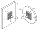
도 1은 정합하는 기계식 체결구를 도시하는 도면.
<도 2a>
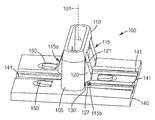
도 2a는 본 발명의 몇몇 실시 형태들에 따른 예시적인 팝-인 기계식 체결구를 도시하는 도면.
<도 2b>
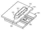
도 2b는 부품 내로의 도 2a의 예시적인 팝-인 기계식 체결구의 삽입을 도시하는 도면.
<도 2c>
도 2c는 도 2a의 예시적인 팝-인 기계식 체결구가 부품 내로 추가로 삽입될 때의 체결구의 탭의 편향을 도시하는 도면.
<도 2d>
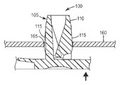
도 2d는 부품 내로의 완전한 삽입 후 도 2a의 예시적인 팝-인 기계식 체결구를 도시하는 도면.
<도 3a>
도 3a는 종래 기술의 로킹 탭을 도시하는 도면.
<도 3b>
도 3b는 도 3a의 종래 기술의 로킹 탭의 로킹 표면을 도시하는 도면.
<도 4a>
도 4a는 도 3b의 종래 기술의 로킹 탭의 로킹 표면과 두꺼운 부품의 상호작용을 도시하는 도면.
<도 4b>
도 4b는 도 3b의 종래 기술의 로킹 탭의 로킹 표면과 중간 두께 부품의 상호작용을 도시하는 도면.
<도 4c>
도 4c는 도 3b의 종래 기술의 로킹 탭의 로킹 표면과 얇은 부품의 상호작용을 도시하는 도면.
<도 5>
도 5는 본 발명의 몇몇 실시 형태들에 따른 예시적인 이중-각도 로킹 탭을 도시하는 도면.
<도 6a>
도 6a는 도 5의 예시적인 로킹 탭의 로킹 표면과 중간 두께 부품 내지 두꺼운 부품의 상호작용을 도시하는 도면.
<도 6b>
도 6b는 도 5의 예시적인 로킹 탭의 로킹 표면과 중간 두께 부품 내지 얇은 부품의 상호작용을 도시하는 도면.
<도 7>
도 7은 본 발명의 몇몇 실시 형태들에 따른 예시적인 다중-각도 로킹 탭을 도시하는 도면.
<도 8>
도 8은 본 발명의 몇몇 실시 형태들에 따른 다른 예시적인 다중-각도 로킹 탭을 도시하는 도면.<Figure 1>
1 shows a mating mechanical fastener.
Figure 2a
2A illustrates an exemplary pop-in mechanical fastener in accordance with some embodiments of the present invention.
Figure 2b
FIG. 2B illustrates the insertion of the exemplary pop-in mechanical fastener of FIG. 2A into a part. FIG.
Figure 2c
FIG. 2C shows the deflection of the tabs of the fastener when the exemplary pop-in mechanical fastener of FIG. 2A is further inserted into the part. FIG.
Figure 2d
FIG. 2D illustrates the exemplary pop-in mechanical fastener of FIG. 2A after complete insertion into a part. FIG.
Figure 3a
3A illustrates a prior art locking tab.
Figure 3b
3B illustrates a locking surface of the prior art locking tab of FIG. 3A.
Figure 4a
4A illustrates the interaction of a thick part with a locking surface of the locking tab of the prior art of FIG. 3B.
Figure 4b
4B illustrates the interaction of the middle surface part with the locking surface of the locking tab of the prior art of FIG. 3B.
Figure 4c
4C illustrates the interaction of a thin part with the locking surface of the locking tab of the prior art of FIG. 3B.
<Figure 5>
5 illustrates an exemplary double-angle locking tab in accordance with some embodiments of the present invention.
Figure 6a
FIG. 6A illustrates the interaction of a medium to thick component with the locking surface of the exemplary locking tab of FIG. 5. FIG.
Figure 6b
FIG. 6B illustrates the interaction of a medium to thin component with the locking surface of the exemplary locking tab of FIG. 5. FIG.
<Figure 7>
7 illustrates an exemplary multi-angle locking tab in accordance with some embodiments of the present invention.
<Figure 8>
8 illustrates another exemplary multi-angle locking tab in accordance with some embodiments of the present invention.
일반적으로, 후크 및 루프(hook and loop) 제품 및 쓰리엠(3M™) 듀얼 로크(DUAL LOCK™) 재폐쇄가능 체결구와 같은 정합하는 기계식 체결구는 접착제 및 용접과 같은 종래의 부착 수단에 대한 대안을 제공한다. 예시적인 정합하는 기계식 체결구가 도 1에 도시되어 있다. 정합하는 기계식 체결구의 제1 절반부(11)는 제1 부품(21)에 접착되는 제1 기부(15), 및 제1 스템(13)(예컨대, 버섯 형상 헤드의 스템)을 포함한다. 정합하는 체결구의 제2 절반부(12)는 제2 부품(22)에 접착되는 제2 기부(16), 및 제2 스템(17)을 포함한다. 일반적으로, 제1 스템(13) 및 제2 스템(17)의 스템 설계(예컨대, 헤드 및 스템 형상, 공간 분포, 및 배향)는 제1 부품(21)을 제2 부품(22)에 기계적으로 결합시키기 위해 제1 스템(13)이 제2 스템(17)과 정합될 때 원하는 상호로킹력 및 분리력을 달성하도록 선택된다.Generally, mating mechanical fasteners such as hook and loop products and 3M ™ DUAL LOCK ™ reclosable fasteners provide an alternative to conventional attachment means such as adhesives and welding. do. An exemplary mating mechanical fastener is shown in FIG. 1. The
그러한 정합하는 기계식 체결구는 하나의 부품을 다른 부품에 해제가능하고 재부착가능하게 기계적으로 결합시키기 위한 효과적인 수단을 제공한다. 일반적으로, 그러한 정합하는 기계식 체결구의 2개의 정합하는 절반부는 하나의 부품의 다른 부품에 대한 기계적 부착을 완료하기 위해 절반부들을 연결시키기 전에 그들 각각의 부품에 부착된다. 흔히, 접착제가 정합하는 기계식 체결구의 각각의 절반부를 그 각각의 부품에 부착시키도록 사용되어, 하나의 부품이 정합하는 기계식 체결구에 의해 다른 부품에 해제가능하고 재부착가능하게 연결될 때 각각의 절반부가 그들의 부품에 부착되어 유지되도록 한다.Such mating mechanical fasteners provide an effective means for mechanically and releasably mechanically coupling one part to another. In general, the two mating halves of such mating mechanical fasteners are attached to their respective parts before joining the halves to complete the mechanical attachment to one part of the other. Often, an adhesive is used to attach each half of the mating mechanical fastener to its respective component, such that each half when one part is releasably and repositionably connected to another component by the mating mechanical fastener To keep them attached to their parts.
정합하는 기계식 체결구의 일부분을 접착제 등을 사용하여 부품에 직접 접착시키는 것에 대한 대안으로서, 정합하는 기계식 체결구가 부착, 예컨대 접착될 수 있는 고정 지점을 제공하도록 팝-인 기계식 체결구가 사용되었다. 본 발명의 몇몇 실시 형태들에 따른 예시적인 팝-인 기계식 체결구가 도 2a 내지 도 2d에 도시되어 있다.As an alternative to directly bonding a portion of the mating mechanical fastener to the part using adhesive or the like, a pop-in mechanical fastener was used to provide a fastening point at which the mating mechanical fastener could be attached, such as glued. Exemplary pop-in mechanical fasteners in accordance with some embodiments of the present invention are shown in FIGS. 2A-2D.
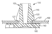
도 2a를 참조하면, 예시적인 팝-인 기계식 체결구(100)는 기부(140) 및 기부에 연결되는 핀(105)을 포함한다. 핀(105)은 삽입 림(110), 및 다른 배향도 가능하긴 하지만 대체로 기부(140)에 수직한 삽입 축(101)에 대해 외향으로 연장하는 적어도 하나의 로킹 탭(115)을 포함한다. 로킹 탭(115)은 삽입 림(110)에 피봇가능하게 연결되고, 윙(120) 및 종단 스템(130)을 포함한다. 윙(120)은 삽입 표면(121) 및 로킹 표면(127)을 포함한다.Referring to FIG. 2A, an exemplary pop-in
몇몇 실시 형태들에서, 팝-인 기계식 체결구는 적어도 2개의 로킹 탭, 그리고 몇몇 실시 형태들에서는 적어도 3개의 로킹 탭을 포함한다. 몇몇 실시 형태들에서, 적어도 하나의 로킹 탭, 예컨대 로킹 탭(115a)은 적어도 하나의 다른 로킹 탭, 예컨대 로킹 탭(115b)에 대향하는 핀(105) 측면 상에 위치된다.In some embodiments, the pop-in mechanical fastener includes at least two locking tabs, and in some embodiments at least three locking tabs. In some embodiments, at least one locking tab, such as
도 2b를 참조하면, 팝-인 기계식 체결구(100)는 핀(105)을 로킹 구멍(165) 내로 삽입시킴으로써 부품(160)에 연결될 수 있다. 삽입 림(110)이 로킹 구멍(165)을 통과한 후에, 로킹 구멍(165)의 주연부(166)가 삽입 표면(121)과 만난다.Referring to FIG. 2B, the pop-in
도 2c를 참조하면, 핀(105)을 로킹 구멍(165) 내로 계속 삽입시키기 위해 삽입력이 인가된다. 일반적으로, 삽입력은 하나 이상의 로킹 탭(들)이 핀(105)의 개방 중앙부 내로 압입될 때, 이 탭(들)(115)을 삽입 림(110)을 중심으로 피봇시켜서, 핀(105)이 로킹 구멍(165)을 통과하도록 하는 데 필요한 힘에 좌우된다.Referring to FIG. 2C, an insertion force is applied to continue inserting the
도 2d를 참조하면, 팝-인 기계식 체결구(100)는 기부(140)가 부품(160)과 접촉할 때 완전히 삽입된다. 일반적으로, 팝-인 기계식 체결구(100)의 설계는 로킹 탭(115)이 핀(105)의 중앙부 외부로 되튀어나가도록 로킹 구멍(165) 및 부품(160)의 치수에 관하여 선택된다. 몇몇 실시 형태들에서, 로킹 구멍(165)의 주연부는 윙(120)의 로킹 표면(127)과 접촉하여, 팝-인 기계식 체결구(100)를 부품(160)에 확고하게 유지시킬 것이다.Referring to FIG. 2D, the pop-in
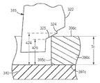
종래 기술의 로킹 탭(315)의 단면도가 도 3a에 도시되어 있다. 로킹 탭(315)은 삽입 림(310)으로부터 팝-인 기계식 체결구의 기부(340)에 인접한 종단 스템(330)까지 연장하는 윙(320)을 포함한다. 윙(320)은 삽입 표면(321), 견부(322), 및 로킹 표면(327)을 포함한다. 로킹 표면(327)은 제1 경사 정지부(323), 제2 경사 정지부(325), 및 이들을 연결하는 단차부(324)로 구성된다.A cross-sectional view of prior
삽입 표면(321)은 기부(340)에 수직한 삽입 축(301)에 대해 각도 A를 형성한다. 각도 A가 커질수록, 팝-인 기계식 체결구를 정위치로 압입시킬 때 요구되는 삽입력이 커진다. 또한, 각도 A가 커질수록, 로킹 탭(315)의 최대 폭 W가 커진다.
도 3b를 참조하면, 제1 경사 정지부(323) 및 제2 경사 정지부(325) 둘 다는 삽입 축(301)에 수직한 윙 축(302a, 302b)에 대해 동일한 각도 B를 형성한다. 각도 B가 작아질수록, 팝-인 기계식 체결구를 분리시킬 때 요구되는 취출력(extraction force)이 커진다. 그러나, 각도 B가 감소함에 따라, 동일한 범위의 높이 H1 및 높이 H2를 제1 경사 정지부(323) 및 제2 경사 정지부(325)에 제공하는 데 요구되는 윙(320)의 폭 W가 커진다. 또한, 윙(320)의 폭이 증가함에 따라, 고정된 높이의 체결구에 대해 요구되는 각도 A가 커져서, 전술한 바와 같이, 삽입력의 바람직하지 못한 증가로 이어진다.Referring to FIG. 3B, both the
도 4a를 참조하면, 부품(390a)은 거리(422)와 거리(423) 사이에 속하는 두께 Ta를 갖는다. 제2 표면(397a)이 기부(340)와 접촉할 때(즉, 팝-인 기계식 체결구가 완전히 삽입될 때), 제1 표면(396a)은 견부(322)를 넘어 지나갔고, 로킹 탭(315)은 제1 표면(396a)이 제1 경사 정지부(323)와 맞물려 부품(390a)을 정위치로 유지시킬 때까지 정위치로 튀어나온다.Referring to FIG. 4A,
도 4b를 참조하면, 부품(390b)은 거리(423)와 거리(424) 사이에 속하는 두께 Tb를 갖는다. 제2 표면(397b)이 기부(340)와 접촉할 때, 제1 표면(396b)은 견부(322)를 넘어 지나갔고, 로킹 탭(315)은 정위치로 튀어나온다. 부품(390b)의 두께 Tb가 거리(423)보다 작기 때문에, 제1 표면(396b)은 제1 경사 정지부(323)와 맞물리지 않고, 오히려 단차부(324)가 로킹 구멍(365b)의 주연부와 만날 때까지 로킹 탭(315)이 외향으로 튀어나온다. 부품(390b)은 기부(340) 부근에서 정위치로 유지되지만, 부품(390b)의 두께 Tb와 거리(423) 사이의 차이에 동등하게 기부(340)의 얼마간의 바람직하지 못한 수직 움직임이 일어날 수 있다.Referring to FIG. 4B,
도 4c를 참조하면, 부품(390c)은 거리(424, 425)들 사이에 속하는 두께 Tc를 갖는다. 팝-인 기계식 체결구가 로킹 구멍(395c) 내로 압입됨에 따라, 제1 표면(396c)이 견부(322)를 넘어 지나가고, 로킹 탭(315)이 정위치로 튀어나오기 시작한다. 우선, 단차부(324)가 로킹 구멍(395c)의 주연부와 만날 때, 탭의 움직임이 정지된다. 추가 삽입력의 인가시, 제2 표면(397c)이 기부(340)와 접촉하고, 제1 표면(396c)이 단차부(324)를 넘어 지나가서, 상부 제1 표면(396c)이 제2 경사 정지부(325)와 맞물릴 때까지 로킹 탭(315)이 끝까지 정위치로 튀어나오도록 하여, 부품(390c)을 정위치로 유지시킨다.Referring to FIG. 4C,
본 발명자는 종래 기술의 로킹 탭을 채용하는 팝-인 기계식 체결구에 대해 여러 결함을 확인하였다. 예를 들어, 소정 부품 두께에 대해, 기부에 수직한 상당한 그리고 바람직하지 못한 움직임이 일어날 수 있다. 또한, 두 경사 정지부들 사이의 단차부의 존재는 탭이 제2 경사 정지부로 진행하기보다는 단차부 상에서 고착 또는 포착(hang-up)될 수 있기 때문에 부적절한 삽입을 초래할 수 있다. 이는 느슨한 끼워맞춤, 낮은 취출력, 및 심지어 고장으로 이어질 수 있다. 마지막으로, 각각 동일한 각도를 갖는 두 경사 정지부의 사용은 수용가능한 수준의 삽입력을 유지시키는 적합한 부품 두께의 범위를 제한할 수 있다.We have identified several deficiencies with pop-in mechanical fasteners employing prior art locking tabs. For example, for a given part thickness, significant and undesirable movements perpendicular to the base may occur. In addition, the presence of the step between the two inclined stops may result in improper insertion since the tab may stick or hang-up on the step rather than proceed to the second inclined stop. This can lead to loose fit, low blowout, and even failure. Finally, the use of two tilt stops, each having the same angle, may limit the range of suitable part thicknesses that maintain an acceptable level of insertion force.
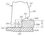
본 발명의 몇몇 실시 형태들에 따른 로킹 탭(515)의 단면도가 도 5에 도시되어 있다. 로킹 탭(515)은 삽입 림(510)으로부터 팝-인 기계식 체결구의 기부(540)에 인접한 종단 스템(530)으로 연장하는 윙(520)을 포함한다. 윙(520)은 삽입 표면(521), 견부(522), 및 로킹 표면(527)을 포함한다. 로킹 표면(527)은 제1 경사 정지부(523) 및 제2 경사 정지부(525)로 구성된다.A cross-sectional view of
삽입 표면(521)은 삽입 축(501)에 대해 각도 C를 형성한다. 각도 C가 커질수록, 팝-인 기계식 체결구를 정위치로 압입시킬 때 요구되는 삽입력이 커진다.
제1 경사 정지부(523)는 삽입 축(501)에 수직한 윙 축(502a)에 대해 각도 D를 형성한다. 유사하게, 제2 경사 정지부(525)는 윙 축(502b)에 대해 각도 E를 형성한다. 각도 D와 E가 작아질수록, 팝-인 기계식 체결구를 분리시킬 때 요구되는 취출력이 커진다. 그러나, 각도 D가 감소함에 따라, 동일한 범위의 높이 H1을 제1 경사 정지부(523)에 제공하는 데 요구되는 윙(520)의 폭 W가 커진다. 유사하게, 취출력을 증가시키는 데 보다 작은 각도 E가 바람직할 수 있지만, 각도 E가 감소함에 따라, 동일한 범위의 높이 H2를 제2 경사 정지부(525)에 제공하는 데 요구되는 윙(520)의 폭 W가 커진다. 또한, 윙(520)의 폭이 증가함에 따라, 고정된 높이의 체결구에 요구되는 각도 C가 커져서, 전술한 바와 같이, 삽입력의 바람직하지 못한 증가로 이어진다.The first
몇몇 실시 형태들에서, 각도 E는 각도 D보다 커서, 제2 경사 정지부(525)에 보다 가파른 경사를 제공한다. 본 발명자는 제2 경사 정지부와 맞물릴 보다 얇은 부품에 대해, 보다 가파른 각도가 여전히 적절하게 큰 분리력을 제공하는 것을 확인하였다. 몇몇 실시 형태들에서, 제1 경사 정지부(523)에 의해 정위치로 유지될 보다 두꺼운 부품에 대해 수용가능한 분리력을 유지시키기 위해 보다 작은 각도 D가 요구될 수 있다. 따라서, 보다 가파른 각도의 제2 단차부 및 보다 작은 각도의 제1 단차부를 조합함으로써, 윙(520)의 폭 W의 바람직하지 못한 증가와 이에 따른 각도 C의 증가로부터 유발되는 삽입력의 바람직하지 못한 증가를 필요로 하지 않고서, 보다 큰 범위의 부품 두께가 수용될 수 있다.In some embodiments, angle E is greater than angle D, providing a steeper slope to
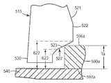
도 6a를 참조하면, 부품(590a)은 최대 정지부 높이(622)(이 실시 형태에서 제1 경사 정지부와 견부 사이의 교차점에 상응함)와, 기부(540)와 제1 경사 정지부(523) 사이의 최소 거리에 상응하는 제1 중간 정지부 높이(623) 사이에 속하는 두께 Ta를 갖는다. 제2 표면(597a)이 기부(540)와 접촉할 때(즉, 팝-인 기계식 체결구가 완전히 삽입될 때), 제1 표면(596a)은 견부(522)를 넘어 지나갔고, 로킹 탭(515)은 상부 제1 표면(596a)이 제1 경사 정지부(523)와 맞물릴 때까지 정위치로 튀어나와서, 부품(590a)을 정위치로 확고하게 유지시킨다. 따라서, 제1 중간 정지부 높이(623)와 최대 정지부 높이(622) 사이의 두께를 갖는 부품에 대해, 팝-인 기계식 체결구는 실질적으로 전혀(예컨대, 전혀) 체결구의 수직 움직임 없이 제1 경사 정지부(523)에 의해 정위치로 확고하게 유지된다.Referring to FIG. 6A, the
도 6b를 참조하면, 부품(590b)은 기부(540)와 제2 경사 정지부(525) 사이의 최대 거리에 상응하는 제2 중간 정지부 높이(624)와, 기부(540)와 제2 경사 정지부(525) 사이의 최소 거리에 상응하는 최소 정지부 높이(625)(이 실시 형태에서 제2 경사 정지부가 종단 스템과 교차하는 지점에 상응함) 사이에 속하는 두께 Tb를 갖는다. 팝-인 기계식 체결구가 로킹 구멍(595) 내로 압입될 때, 제1 표면(596b)은 견부(522)를 넘어 지나가고, 로킹 탭(515)은 정위치로 튀어나오기 시작한다.Referring to FIG. 6B,
우선, 탭의 움직임은 그것과 제1 경사 정지부와의 접촉에 의해 안내될 수 있다. 제1 경사 표면과 제2 경사 표면 사이에 단차부를 포함하였던 종래 기술의 로킹 탭과는 달리, 제1 경사 정지부(523)와 제2 경사 정지부(525) 사이의 전이부에서 추가 삽입력이 거의 또는 전혀 요구되지 않는다. 제1 경사 정지부(523)와 제2 경사 정지부(525) 사이에 그러한 단차부가 없기 때문에, 제1 중간 정지부 높이(623)(기부와 제1 경사 정지부 사이의 최소 거리에 상응함)는 제2 중간 정지부 높이(624)(기부와 제1 경사 정지부 사이의 최대 거리에 상응함)와 같다. 몇몇 실시 형태들에서, 예컨대 제조 정밀도의 변동으로 인해, 제1 경사 정지부와 제2 경사 정지부 사이에 약간의 단차부가 존재할 수 있다. 그러한 실시 형태들에서, 제1 중간 정지부 높이는 제2 중간 정지부 높이를 그들 사이의 단차부의 높이와 같은 크기만큼 초과할 것이다.First, the movement of the tab can be guided by the contact of it with the first tilt stop. Unlike the locking tabs of the prior art, which included a step between the first inclined surface and the second inclined surface, an additional insertion force is applied at the transition between the first
제2 표면(597b)이 기부(540)와 접촉할 때, 로킹 탭(515)은 제1 표면(596b)이 제2 경사 정지부(525)와 맞물릴 때까지 정위치로 끝까지 튀어나와서, 부품(590b)을 정위치로 유지시킨다.When the
특정한 팝-인 기계식 체결구와 함께 사용하기에 적합한 부품 두께의 범위는 로킹 표면의 설계에 부분적으로 좌우된다. 구체적으로, 부품 두께의 범위는 대체로 최대 정지부 높이(622)와 최소 정지부 높이(625) 사이의 차이와 같다. 일반적으로, 실제 최대 부품 두께 및 최소 부품 두께는 종단 스템과 기부 사이의 간극뿐만 아니라 종단 스템의 높이에 의해서도 영향을 받을 것이지만, 부품 높이의 범위(즉, 최대 정지부 높이와 최소 정지부 높이 사이의 차이)는 이들 파라미터에 의해 영향을 받지 않을 것이다.The range of component thicknesses suitable for use with certain pop-in mechanical fasteners depends in part on the design of the locking surface. Specifically, the range of component thicknesses is generally equal to the difference between the
따라서, 로킹 표면의 설계를 변화시키지 않고서 그리고 수용될 수 있는 부품 높이의 범위에 영향을 주지 않고서, 본 발명에 따른 팝-인 기계식 체결구는 종단 스템과 기부 사이의 간극 및/또는 종단 스템의 길이를 조절함으로써 상이한 최소 및 최대 부품 높이를 수용하도록 쉽게 변형될 수 있다. 예를 들어, 팝-인 기계식 체결구는 1.2 ㎜의, 최대 정지부 높이와 최소 정지부 높이 사이의 차이를 제공하는 로킹 표면을 구비하도록 설계될 수 있다. 종단 스템의 길이와 간극의 합을 1 ㎜이도록 선택함으로써, 그러한 체결구는 약 1 ㎜ 내지 약 2.2 ㎜ 두께 범위의 부품을 수용할 것이다. 단순히 종단 스템의 길이와 간극의 합을 3 ㎜이도록 선택함으로써, 동일한 체결구 설계가 약 3 ㎜ 내지 약 4.2 ㎜ 두께 범위의 부품을 수용할 것이다.Thus, without changing the design of the locking surface and without affecting the range of component heights that can be accommodated, the pop-in mechanical fasteners according to the present invention allow for a gap between the end stem and the base and / or the length of the end stem. By adjusting it can be easily modified to accommodate different minimum and maximum part heights. For example, a pop-in mechanical fastener can be designed with a locking surface that provides a difference between the maximum stop height and the minimum stop height of 1.2 mm. By selecting the sum of the length and the gap of the end stem to be 1 mm, such fasteners will accommodate parts in the thickness range of about 1 mm to about 2.2 mm. By simply choosing the sum of the length and gap of the end stem to be 3 mm, the same fastener design will accommodate parts in the thickness range of about 3 mm to about 4.2 mm.
도 2a를 참조하면, 스프링 탭(150)의 사용은 특정한 로킹 표면 설계에 대한 부품 두께의 유용한 범위를 확대시킬 수 있다. 일반적으로, 스프링 탭(150)은 기부(140)의 상부 표면에 피봇가능하게 연결된다. 삽입 전에, 스프링 탭은 기부의 표면으로부터 멀리 위로 기울어져 있지만, 스프링 탭이 기부의 상부 표면과 동일 높이에 있도록 스프링 탭이 기부 내로 편향되도록 하는 공간이 스프링 탭 아래에 있다.With reference to FIG. 2A, the use of
도 6b를 참조하면, 부품 두께가 최소 정지부 높이(625)를 초과할 때, 부품(590b)의 상부는 부품의 하부 표면이 기부(540)에 대해 가압되었을 때 로킹 표면(527)과 맞물릴 것이다. 그러나, 부품 두께가 최소 정지부 높이 미만이었으면, 부품의 상부는 로킹 표면 아래의 어딘가에 위치되어, 얼마간의 바람직하지 못한 수직 움직임을 유발했을 것이다. 스프링 탭(150)을 포함함으로써, 기부의 상부 표면 위로 상승된, 스프링 탭의 상부에 보다 얇은 부품이 놓일 것이다. 따라서, 이들 보다 얇은 부품은 로킹 표면과 접촉할 것이고, 수직 움직임을 제거할 것이다. 스프링 탭이 기부 내로 굽혀질 수 있고 기부와 동일 높이로 될 수 있기 때문에, 스프링 탭의 존재는 사용될 수 있는 부품 두께의 상한을 변경시키지 않는다. 또한, 스프링 탭이 보다 두꺼운 부품을 수용하도록 굽혀질 때, 스프링 탭의 굽힘에 대한 저항력은 부품을 로킹 표면에 대해 가압시키는 얼마간의 상향력을 제공하여, 임의의 수직 움직임을 더욱 최소화시킬 수 있다.6B, when the part thickness exceeds the
비록 전술한 이중-각도 탭이 많은 상황에 적합하긴 하지만, 2개 초과의 경사 정지부, 예컨대 3개 또는 심지어 4개 이상의 경사 정지부를 포함하는 것이 바람직할 수 있다. 극단적으로, 로킹 표면은 무한한 수의 경사 정지부를 구비한 곡선형 정지부를 포함할 수 있다. 그러한 실시 형태가 다음과 같이 도 7 및 도 8에 예시되어 있다.Although the aforementioned double-angle tab is suitable for many situations, it may be desirable to include more than two inclined stops, such as three or even four or more inclined stops. Extremely, the locking surface may comprise a curved stop with an infinite number of inclined stops. Such an embodiment is illustrated in FIGS. 7 and 8 as follows.
본 발명의 몇몇 실시 형태들에 따른 로킹 탭(715)의 단면도가 도 7에 도시되어 있다. 로킹 탭(715)은 삽입 림(710)으로부터 팝-인 기계식 체결구의 기부(740)에 인접한 종단 스템(730)으로 연장하는 윙(720)을 포함한다. 윙(720)은 삽입 표면(721), 견부(722), 및 로킹 표면(727)을 포함한다. 로킹 표면(727)은 제1 경사 정지부(723), 제2 경사 정지부(725), 및 제3 경사 정지부(726)로 구성된다.A cross-sectional view of a
삽입 표면(721)은 삽입 축(701)에 대해 각도 J를 형성한다. 각도 J가 커질수록, 팝-인 기계식 체결구를 정위치로 압입시킬 때 요구되는 삽입력이 커진다.
제1 경사 정지부(723)는 삽입 축(701)에 수직한 윙 축(702a)에 대해 각도 K를 형성한다. 유사하게, 제2 경사 정지부(725)는 윙 축(702b)에 대해 각도 L을 형성하고, 제3 경사 정지부(726)는 윙 축(702c)에 대해 각도 M을 형성한다. 각도 K, L, 및 M이 작아질수록, 팝-인 기계식 체결구를 분리시킬 때 요구되는 취출력이 커진다. 그러나, 각도가 감소함에 따라, 윙(720)의 폭 W는 각각의 경사 정지부의 각각에 동일한 범위의 높이를 제공하기 위해 증가하여야 한다. 또한, 윙(720)의 폭이 증가함에 따라, 고정된 높이의 체결구에 요구되는 각도 J가 커져서, 전술한 바와 같이, 삽입력의 바람직하지 못한 증가로 이어진다.The first tilt stop 723 forms an angle K with respect to the
몇몇 실시 형태들에서, 각도 L은 각도 K보다 커서, 제2 경사 정지부(725)에 보다 가파른 경사를 제공한다. 몇몇 실시 형태들에서, 각도 M은 각도 L보다 커서, 제3 경사 정지부(726)에 보다 가파른 경사를 제공한다. 몇몇 실시 형태들에서, 경사 정지부의 수에 무관하게, 정지부의 각도는 정지부가 탭의 견부로부터 종단 스템으로 진행함에 따라 증가한다. 도 7을 참조하면, 이는 각도 L이 각도 K보다 크고 각도 M이 각도 L보다 큰 결과를 유발할 것이다. 일반적으로, 본 발명자는 보다 가파른 각도의 정지부와 맞물릴 보다 얇은 부품에 대해, 보다 가파른 각도가 충분히 큰 분리력을 제공하는 것을 확인하였다. 몇몇 실시 형태들에서, 점차 작아지는 각도의 정지부에 의해 정위치로 유지될 보다 두꺼운 부품에 대해 수용가능한 분리력을 유지시키기 위해 보다 작은 각도가 요구될 수 있다. 따라서, 연속하는 경사 정지부를 제공함으로써, 윙(720)의 폭 W의 바람직하지 못한 증가와 이에 따른 각도 J의 증가로부터 유발되는 삽입력의 바람직하지 못한 증가를 필요로 하지 않고서, 보다 큰 범위의 부품 두께가 수용될 수 있다.In some embodiments, the angle L is greater than the angle K, providing a steeper slope to the
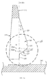
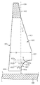
이러한 발견은 도 8에 도시된 바와 같은 곡선형 로킹 표면을 구비한 팝-인 기계식 체결구로 확대될 수 있다. 일반적으로, 곡선을 따른 임의의 점에 대한 접선은 경사 정지부를 한정하고, 따라서, 곡선형 표면은 무한한 수의 경사 정지부를 구비하는 것으로 간주될 수 있다. 비록 도 8이 단일 곡선으로 구성되는 로킹 표면을 도시하지만, 선형 및 곡선형 정지부를 조합한 로킹 표면뿐만 아니라 복합 곡선형 로킹 표면도 사용될 수 있다.This finding can be extended to pop-in mechanical fasteners with curved locking surfaces as shown in FIG. 8. In general, the tangent to any point along the curve defines the slope stop, and thus the curved surface can be considered to have an infinite number of slope stops. Although FIG. 8 shows a locking surface composed of a single curve, complex curved locking surfaces as well as locking surfaces combining linear and curved stops may be used.
도 8을 참조하면, 로킹 탭(815)은 삽입 림(810)으로부터 팝-인 기계식 체결구의 기부(840)에 인접한 종단 스템(830)으로 연장하는 윙(820)을 포함한다. 윙(820)은 삽입 표면(821), 견부(822), 및 곡선형 로킹 표면(827)을 포함한다.Referring to FIG. 8, the
삽입 표면(821)은 삽입 축(801)에 대해 각도 P를 형성한다. 각도 P가 커질수록, 팝-인 기계식 체결구를 정위치로 압입시킬 때 요구되는 삽입력이 커진다.
선(803a)은 견부(822) 부근에서 로킹 표면(827)에 접하고, 삽입 축(801)에 수직한 윙 축(802a)에 대해 각도 Q를 형성한다. 유사하게, 선(803c)은 종단 스템(830) 부근에서 로킹 표면(827)에 접하고, 윙 축(802c)에 대해 각도 S를 형성한다. 각각 삽입 축(801)에 수직한 윙 축에 대해 각도를 형성하는 무한한 수의 접선이 선(803a, 803c)들 사이에 그려질 수 있다. 예를 들어, 선(803b)은 선(803a, 803c)들 사이의 임의의 위치에서 로킹 표면(827)에 접하고, 윙 축(802b)에 대해 각도 R을 형성한다. 몇몇 실시 형태들에서, 로킹 표면(827)은 오목하며, 즉 로킹 표면(827)에 접하는 선의 각도가 견부(822)로부터 종단 스템(830)까지 로킹 표면(827)의 경로를 따라 증가한다.Line 803a abuts locking
팝-인 기계식 체결구는 예컨대 사출 성형을 비롯한 임의의 공지된 수단에 따라 제조될 수 있다. 사출 주형은 원하는 부품 설계를 형성하도록 표준 공정을 이용하여 제조될 수 있다. 일반적으로, 팝-인 기계식 체결구는 열가소성재, 탄성중합체, 열가소성 탄성중합체, 경화성 수지(예컨대, 열경화성, 수분 경화성, 및 방사선 경화성 수지) 등을 비롯한 임의의 적합한 재료로부터 형성(예컨대, 사출 성형)될 수 있다. 몇몇 실시 형태들에서, 우수한 탄성 회복 특성 및 인장 강도를 나타내는 재료(예컨대, 열가소성 중합체)가 사용될 수 있다. 몇몇 실시 형태들에서, 비교적 습도에 민감하지 않고 최대 섭씨 120도(℃)(화씨 250도)까지 적합한 인장 특성을 갖는 중합체가 사용될 수 있다. 사용될 수 있는 적합한 열가소성 수지의 예는 폴리프로필렌, 반결정질 중합체 수지, 예컨대 폴리올레핀 및 폴리올레핀 공중합체(예컨대, 폴리에틸렌, 폴리프로필렌, 에틸렌-프로필렌 공중합체 등과 같이 2개 내지 8개의 탄소 원자를 갖는 단량체에 기반함), 폴리에스테르, 코-폴리에스테르, 나일론, 폴리아미드, 코-폴리아미드, 플루오르화 단일중합체 및 공중합체, 폴리알킬렌 옥사이드(예컨대, 폴리에틸렌 옥사이드 및 폴리프로필렌 옥사이드), 아이오노머(예컨대, 염기 또는 염으로 중화된 에틸렌-메타크릴산 공중합체), 셀룰로오스 아세테이트, 폴리아크릴로니트릴, 폴리비닐 클로라이드, 열가소성 폴리우레탄, 에폭시(예컨대, 방향족 에폭시), 폴리카르보네이트, 비정질 폴리에스테르, 비정질 폴리아미드, ABS 공중합체, 및 폴리페닐렌 옥사이드 얼로이(alloy)를 포함한다. 몇몇 실시 형태들에서, 폴리프로필렌이 바람직할 수 있다.Pop-in mechanical fasteners can be made according to any known means, including, for example, injection molding. Injection molds can be made using standard processes to form the desired part design. In general, the pop-in mechanical fasteners may be formed (eg, injection molded) from any suitable material, including thermoplastics, elastomers, thermoplastic elastomers, curable resins (eg, thermoset, moisture curable, and radiation curable resins) and the like. Can be. In some embodiments, a material (eg, a thermoplastic polymer) that exhibits good elastic recovery properties and tensile strength can be used. In some embodiments, polymers may be used that are relatively insensitive to humidity and have suitable tensile properties up to 120 degrees Celsius (250 degrees Fahrenheit). Examples of suitable thermoplastic resins that can be used are based on monomers having 2 to 8 carbon atoms, such as polypropylene, semicrystalline polymer resins such as polyolefins and polyolefin copolymers (eg polyethylene, polypropylene, ethylene-propylene copolymers, etc.). ), Polyesters, co-polyesters, nylons, polyamides, co-polyamides, fluorinated homopolymers and copolymers, polyalkylene oxides (such as polyethylene oxide and polypropylene oxide), ionomers (such as base Or ethylene-methacrylic acid copolymer neutralized with salt), cellulose acetate, polyacrylonitrile, polyvinyl chloride, thermoplastic polyurethane, epoxy (e.g. aromatic epoxy), polycarbonate, amorphous polyester, amorphous polyamide , ABS copolymer, and polyphenylene oxide alloy (a lloy). In some embodiments, polypropylene may be desirable.
일반적으로, 팝-인 기계식 체결구가 형성되면, 그것은 핀의 삽입에 적합한 개구를 갖는 임의의 부품에 부착될 수 있다. 이어서, 핀에 대향하는 기부의 주 표면(즉, 기부의 노출된 주 표면)은 예컨대 접착제에 의한 다른 부품의 부착을 비롯한 임의의 원하는 용도로 이용가능하다.In general, once a pop-in mechanical fastener is formed, it can be attached to any part having an opening suitable for insertion of a pin. Subsequently, the major surface of the base opposite the pin (ie, the exposed major surface of the base) is available for any desired use, including, for example, attachment of other components by an adhesive.
몇몇 실시 형태들에서, 정합하는 기계식 체결구의 하나의 절반부가 기부의 노출된 주 표면에 부착될 수 있다. 기계식 체결구를 부착시키기에 적합한 방법은 접착제(예컨대, 감압 접착제), 초음파 접합, 삽입 성형, 및 체결구를 기부에 접합시키는 용융된 중합체 층의 압출을 포함한다. 일반적으로, 기부에 대한 정합하는 기계식 체결구의 접합력은 팝-인 기계식 체결구 분리 강도(즉, 팝-인 기계식 체결구를 분리시키는 데(또는 그의 분리 시도 중에 파괴시키는 데) 요구되는 힘)보다 강하다.In some embodiments, one half of the mating mechanical fastener can be attached to the exposed major surface of the base. Suitable methods for attaching mechanical fasteners include adhesives (eg, pressure sensitive adhesives), ultrasonic bonding, insert molding, and extrusion of a molten polymer layer that joins the fasteners to the base. In general, the joining force of the mating mechanical fastener to the base is stronger than the pop-in mechanical fastener separation strength (i.e., the force required to disengage the pop-in mechanical fastener (or destroy it during its disengagement attempt)). .
몇몇 실시 형태들에서, 동일한 또는 상이한 설계의 2개의 팝-인 기계식 체결구를 조합시키는 것이 유용할 수 있다. 예를 들어, 두 부품을 함께 접합시킬 때, 제1 부품의 전형적인 두께의 범위에 걸쳐 유용한 제1 팝-인 기계식 체결구를 설계하는 것이 유용할 수 있다. 제2 팝-인 기계식 체결구는 제2 부품에 대한 전형적인 두께 범위에 걸쳐 사용되도록 설계될 수 있다. 이들 두 팝-인 기계식 체결구의 기부는 직접적으로 또는 간접적으로(예컨대, 접착제의 사용을 통해) 서로 접합될 수 있다. 사용시, 제1 팝-인 기계식 체결구의 스템은 제1 부품 내의 적절한 구멍 내로 삽입될 것이어서, 제2 팝-인 기계식 체결구의 스템을 노출된 상태로 남게 할 것이다. 이어서, 제2 부품 내의 적절한 구멍은 제2 스템과 정렬될 수 있고, 제2 부품은 제2 팝-인 기계식 체결구에 의해 유지되면서 정위치로 압입될 수 있다. 기부 두께의 적절한 선택에 의해, 부품들 사이의 원하는 정도의 편위(set-off)가 달성될 수 있다. 또한, 양쪽 팝-인 기계식 체결구의 적절한 설계를 통해, 부품들이 최소한의 수직 움직임을 갖고서 또는 전혀 수직 움직임 없이 일정 범위의 두께에 걸쳐 정위치로 확고하게 유지될 수 있다.In some embodiments, it may be useful to combine two pop-in mechanical fasteners of the same or different designs. For example, when joining two parts together, it may be useful to design a first pop-in mechanical fastener that is useful over a range of typical thicknesses of the first part. The second pop-in mechanical fastener can be designed for use over a typical thickness range for the second part. The bases of these two pop-in mechanical fasteners can be joined to each other directly or indirectly (eg, through the use of an adhesive). In use, the stem of the first pop-in mechanical fastener will be inserted into an appropriate hole in the first part, leaving the stem of the second pop-in mechanical fastener exposed. A suitable hole in the second part can then be aligned with the second stem, and the second part can be pressed into place while being held by the second pop-in mechanical fastener. By appropriate selection of the base thickness, a desired degree of set-off between the parts can be achieved. In addition, with the proper design of both pop-in mechanical fasteners, the parts can be held firmly in place over a range of thicknesses with minimal vertical movement or no vertical movement at all.
일반적으로, 본 발명의 기계식 체결구는 연속적으로 또는 개별적으로 제조될 수 있다. 몇몇 실시 형태들에서, 팝-인 기계식 체결구는 정합하는 기계식 체결구의 하나의 절반부의 연속 스트립을 기부의 노출된 주 표면에 라미네이팅하는 라미네이터와 정렬되어 그 내부로 공급된다. 이어서, 개별 팝-인 기계식 체결구는 그에 부착된 정합하는 기계식 체결구의 하나의 절반부를 구비한 개별 팝-인 기계식 체결구로 분할될 수 있다.In general, the mechanical fasteners of the present invention can be produced continuously or separately. In some embodiments, the pop-in mechanical fastener is aligned with and fed into the laminator laminating the continuous strip of one half of the mating mechanical fastener to the exposed major surface of the base. The individual pop-in mechanical fasteners can then be divided into individual pop-in mechanical fasteners with one half of the mating mechanical fasteners attached thereto.
일반적으로, 본 발명에 따른 팝-인 기계식 체결구의 다양한 부품의 치수는 팝-인 기계식 체결구가 수용할 수 있는 부품의 두께 범위, 및 핀의 삽입을 가능하게 하는 데 요구되는 부품 내의 구멍에 대한 허용가능한 치수를 비롯한 다수의 인자에 좌우될 것이다.In general, the dimensions of the various parts of the pop-in mechanical fastener according to the present invention are dependent upon the range of thicknesses of the parts that the pop-in mechanical fastener can accommodate, and the holes in the parts required to enable the insertion of the pins. It will depend on a number of factors including acceptable dimensions.
하기의 치수로 한정되지는 않지만, 특정한 응용을 위한 설계 기준이 치수 선택시 당업자를 안내하도록 기술된다. 자동차 산업에서, 대부분의 부품(예컨대, 패널) 두께는 0.70 ㎜와 1.20 ㎜ 사이에서 변화된다. 따라서, 하나의 팝-인 기계식 체결구 설계가 패널 두께의 전체 범위를 수용할 수 있으면서도 현재 설계에 전형적인 수직 또는 측방향 움직임을 나타내지 않는 것이 유리할 수 있다. 기계식 체결구의 움직임은 예컨대 자동차 산업에서 수용할 수 없는 덜거덕거리는 소리 및 소음을 유발할 수 있다.Although not limited to the following dimensions, design criteria for specific applications are described to guide those skilled in the art in selecting dimensions. In the automotive industry, most component (eg, panel) thicknesses vary between 0.70 mm and 1.20 mm. Thus, it may be advantageous for one pop-in mechanical fastener design to accommodate the full range of panel thicknesses while not exhibiting vertical or lateral movements typical of current designs. The movement of mechanical fasteners can cause rattling sounds and noises that are unacceptable in the automotive industry, for example.
전형적으로, 기부의 치수는 중요하지 않으며, 접합에 요구되는 표면적, 기계적 강도, 및 비용과 같은 잘-이해된 기준에 기초하여 선택될 수 있다. 일반적으로, 핀 치수는 많은 치수가 상호관련되고 하나의 치수(예컨대, 핀의 폭)의 선택이 다른 치수(예컨대, 삽입 각도)의 선택을 제한할 수 있기 때문에, 추가 기준에 기초하여 선택될 것이다.Typically, the dimensions of the base are not critical and can be selected based on well-understood criteria such as the surface area, mechanical strength, and cost required for bonding. In general, the pin dimensions will be selected based on additional criteria because many dimensions are correlated and the choice of one dimension (eg pin width) may limit the choice of another dimension (eg insertion angle). .
"전체 핀 높이"는 기부의 상부 표면으로부터 핀의 상부 에지까지의 거리로서 정의된다. 일반적으로, 비용 및 공간 고려사항 둘 다로 인해 이 치수를 최소화시키는 것이 바람직하다. 예를 들어, 핀은 구멍을 통해 연장할 것이어서, 패널 후방에 핀을 수용하기에 적절한 공간이 있어야 한다. 그러나, 최소의 전체 핀 높이는 마주칠 수 있는 패널 두께의 전체 범위를 수용하여야 한다. 몇몇 실시 형태들에서, 전체 핀 높이는 최대의 의도된 패널 두께의 적어도 5배, 예컨대 최대 패널 두께의 적어도 6배, 또는 심지어 7배일 수 있다. 몇몇 실시 형태들에서, 전체 핀 높이는 최대의 의도된 패널 두께의 10배 이하, 예컨대 9배 이하, 또는 심지어 8배 이하일 수 있다. 예를 들어, 전술한 자동차 응용에 대해서, 1.2 ㎜의 최대의 의도된 패널 두께에 대해 8 내지 9 ㎜(예컨대, 8.55 ㎜)의 전체 핀 높이가 사용될 수 있다."Total fin height" is defined as the distance from the upper surface of the base to the upper edge of the fin. In general, it is desirable to minimize this dimension because of both cost and space considerations. For example, the pin will extend through the hole, so there must be adequate space behind the panel to accommodate the pin. However, the minimum overall pin height must accommodate the full range of panel thicknesses encountered. In some embodiments, the overall pin height can be at least five times the maximum intended panel thickness, such as at least six times, or even seven times the maximum panel thickness. In some embodiments, the overall pin height can be 10 times or less, such as 9 times or less, or even 8 times or less of the maximum intended panel thickness. For example, for the aforementioned automotive applications, an overall fin height of 8 to 9 mm (eg, 8.55 mm) can be used for a maximum intended panel thickness of 1.2 mm.
일반적으로, 핀의 벽은 핀의 개방 중앙부를 둘러싸고 핀의 형상을 한정한다. 핀 폭은 탭에 평행하게 측정된다. 핀 두께는 핀의 벽의 두께로서 정의된다. 몇몇 실시 형태들에서, 핀의 벽은 핀의 높이를 따라 일정한 두께를 갖는다. 몇몇 실시 형태들에서, 핀 벽은 삽입 에지 부근에서 테이퍼진다. 일반적으로, 움직임을 방지하거나 최소화시키기 위해 부품의 구멍 내로의 핀의 꼭 맞는 끼워맞춤이 바람직하다 그러나, 구멍 내로의 핀의 삽입을 더욱 쉽게 개시하도록 삽입 에지를 테이퍼지게 하는 것이 바람직할 수 있다.Generally, the wall of the fin surrounds the open center of the fin and defines the shape of the fin. Pin width is measured parallel to the tab. Fin thickness is defined as the thickness of the wall of the fin. In some embodiments, the wall of the fin has a constant thickness along the height of the fin. In some embodiments, the pin wall is tapered near the insertion edge. In general, a tight fit of the pin into the hole of the part is desirable to prevent or minimize movement. However, it may be desirable to taper the insertion edge to more easily initiate the insertion of the pin into the hole.
이전에 논의된 바와 같이, 탭의 폭은 다음의 인자, 즉 핀 높이, 삽입 각도, 경사 정지부의 높이, 및 경사 정지부의 상대 각도 중 적어도 하나에 좌우된다. 또한, 최대 핀 폭은 핀 내의 이용가능한 개방 공간에 의해 영향을 받는다.As previously discussed, the width of the tab depends on at least one of the following factors: pin height, insertion angle, height of the inclined stop, and relative angle of the inclined stop. In addition, the maximum pin width is influenced by the open space available in the pin.
핀 폭과 핀 두께는 핀 내의 개방부의 폭을 제어하며, 이는 탭의 크기를 제한한다. 구체적으로, 핀이 부품 내의 구멍 내로 삽입될 때, 탭(들)은 핀의 개방 중앙부 내로 편향된다. 탭이 핀의 대향하는 내부 표면과 만날 때, 그들은 더 이상 굽혀질 수 없다. 따라서, 최대 탭 폭은 탭의 편향에 평행한 핀 내의 개방 영역에 의해 영향을 받는다.The pin width and pin thickness control the width of the opening in the pin, which limits the size of the tab. Specifically, when the pin is inserted into a hole in the part, the tab (s) are deflected into the open center of the pin. When the tabs meet the opposing inner surfaces of the pins, they can no longer bend. Thus, the maximum tab width is affected by the open area in the pin parallel to the deflection of the tab.
삽입 각도는 예컨대 핀 높이, 탭의 원하는 폭, 핀 내의 편향에 이용가능한 공간, 및 원하는 삽입력에 기초하여 선택될 수 있다. 몇몇 실시 형태들에서, 삽입 각도는 45도 이하, 예컨대 30도 이하, 또는 심지어 25도 이하이다. 몇몇 실시 형태들에서, 삽입 각도는 적어도 13도, 예컨대 적어도 18도이다. 몇몇 실시 형태들에서, 삽입 각도는 20 내지 25도, 예컨대 23도이다.The insertion angle can be selected based on, for example, the pin height, the desired width of the tab, the space available for deflection in the pin, and the desired insertion force. In some embodiments, the insertion angle is 45 degrees or less, such as 30 degrees or less, or even 25 degrees or less. In some embodiments, the insertion angle is at least 13 degrees, such as at least 18 degrees. In some embodiments, the insertion angle is 20 to 25 degrees, such as 23 degrees.
일반적으로, 제1 경사 정지부의 각도는 삽입 각도, 제1 경사 정지부의 원하는 높이, 및 핀 내의 이용가능한 편향 공간에 기초하여 선택될 수 있다. 몇몇 실시 형태들에서, 제1 각도는 적어도 1도, 예컨대 적어도 5도, 또는 심지어 적어도 15도이다. 몇몇 실시 형태들에서, 제1 각도는 45도 이하, 예컨대 40도 이하이다. 몇몇 실시 형태들에서, 제1 각도는 20 내지 30도, 예컨대 27도이다. 유사하게, 제2 경사 정지부의 각도는 삽입 각도, 제2 경사 정지부의 원하는 높이, 및 핀 내의 이용가능한 편향 공간에 기초하여 선택될 수 있다. 제2 각도는 제1 각도보다 크지만, 90° 미만이다. 몇몇 실시 형태들에서, 제2 각도는 제1 각도보다 적어도 5도만큼, 예컨대 적어도 10도만큼, 또는 심지어 적어도 20도만큼 크다. 몇몇 실시 형태들에서, 제2 각도는 적어도 25도, 예컨대 적어도 35도이다. 몇몇 실시 형태들에서, 제2 각도는 70도 이하, 예컨대 65도 이하이다. 몇몇 실시 형태들에서, 제2 각도는 27 내지 65도, 예컨대 40 내지 50도, 예컨대 47도이다.In general, the angle of the first tilt stop may be selected based on the insertion angle, the desired height of the first tilt stop, and the available deflection space in the pin. In some embodiments, the first angle is at least 1 degree, such as at least 5 degrees, or even at least 15 degrees. In some embodiments, the first angle is 45 degrees or less, such as 40 degrees or less. In some embodiments, the first angle is 20 to 30 degrees, such as 27 degrees. Similarly, the angle of the second tilt stop may be selected based on the insertion angle, the desired height of the second tilt stop, and the available deflection space in the pin. The second angle is greater than the first angle but less than 90 °. In some embodiments, the second angle is at least 5 degrees greater than the first angle, such as at least 10 degrees, or even at least 20 degrees. In some embodiments, the second angle is at least 25 degrees, such as at least 35 degrees. In some embodiments, the second angle is 70 degrees or less, such as 65 degrees or less. In some embodiments, the second angle is 27 to 65 degrees, such as 40 to 50 degrees, such as 47 degrees.
제1 경사 정지부의 높이는 전형적으로 전체 핀 높이, 핀 내의 이용가능한 편향 공간, 제1 경사 정지부의 각도와 제2 경사 정지부의 각도, 및 부품 두께의 원하는 범위에 기초하여 선택된다. 유사하게, 제2 경사 정지부의 높이는 전형적으로 전체 핀 높이, 핀 내의 이용가능한 편향 공간, 제1 경사 정지부의 각도와 제2 경사 정지부의 각도, 및 부품 두께의 원하는 범위에 기초하여 선택된다.The height of the first inclined stop is typically selected based on the overall fin height, the available deflection space in the fin, the angle of the first inclined stop and the angle of the second inclined stop, and the desired range of part thicknesses. Similarly, the height of the second tilt stop is typically selected based on the overall fin height, the available deflection space in the pin, the angle of the first tilt stop and the angle of the second tilt stop, and the desired range of part thicknesses.
이전에 기재된 자동차 예에 대해, 제1 경사 정지부의 높이는 0.25 내지 0.35 ㎜, 예컨대 0.31 ㎜일 수 있다. 제2 경사 정지부의 높이는 0.75 내지 0.9 ㎜, 예컨대 0.8 내지 0.85 ㎜, 예컨대 0.82 ㎜일 수 있다.For the previously described motor vehicle example, the height of the first inclined stop may be 0.25 to 0.35 mm, such as 0.31 mm. The height of the second tilt stop may be 0.75 to 0.9 mm, such as 0.8 to 0.85 mm, such as 0.82 mm.
일반적으로, 경사 정지부의 전체 높이(즉, 제1 경사 정지부와 제2 경사 정지부의 높이의 합)는 최대 예상 부품 두께보다 커야 하고, 원하는 부품 두께 범위를 수용하기에 충분하여야 한다. 예상 패널 두께가 0.70 내지 1.20 ㎜ 범위인 자동차 예에 대해, 경사 정지부의 전체 높이는 0.50 ㎜이어야 한다. 예를 들어, 1.13 ㎜의 전체 높이가 0.65 내지 1.30 ㎜의 부품 두께 범위, 또는 0.65 ㎜의 전체 범위를 포함하는 나타났다.In general, the overall height of the inclined stop (ie, the sum of the heights of the first inclined stop and the second inclined stop) should be greater than the maximum expected part thickness and should be sufficient to accommodate the desired part thickness range. For a motor vehicle example where the expected panel thickness ranges from 0.70 to 1.20 mm, the overall height of the inclined stop should be 0.50 mm. For example, a total height of 1.13 mm appeared to cover a part thickness range of 0.65 to 1.30 mm, or a full range of 0.65 mm.
[실시예][Example]
팝-인 기계식 체결구를 표 1에 기재된 치수에 따라 설계하였다. 체결구는 실질적으로 동일한 치수를 갖는 3개의 탭을 포함하였다. 2개의 탭을 핀의 하나의 측면 상에 위치시켰고, 제3 탭을 핀의 대향하는 측면 상에 위치시켰다. 이러한 예시적인 팝-인 기계식 체결구가 도 2a에 도시되어 있고, 탭이 도 5에 도시되어 있다.Pop-in mechanical fasteners were designed according to the dimensions listed in Table 1. The fastener included three tabs having substantially the same dimensions. Two tabs were placed on one side of the pin and a third tab was placed on the opposite side of the pin. This exemplary pop-in mechanical fastener is shown in FIG. 2A and the tab is shown in FIG. 5.

폴리프로필렌 수지(미국 델라웨어주 윌밍턴 소재의 하이몬트 유.에스.에이., 인크.(Himont U.S.A., Inc.)로부터 입수한 PROF-FAX 6523 폴리프로필렌 수지)를 폴리프로필렌 수지 100부 당 2부의 흑색 농축물(미국 노스 캐롤라이나주 샬롯 소재의 클라리언트 코포레이션(Clariant Corp.)으로부터 입수한 CBK 00010 블랙(Black))로 착색하였다. 착색된 수지를 원하는 치수에 따라 사출 성형하였다. 도 2a를 참조하면, 팝-인 기계식 체결구를 형성하도록 사용된 사출 성형 공정 중 재료가 유동하도록 하기 위해 기부(140)의 상부 표면 내에 홈(141)을 제공하였다. 그러한 홈은 아주 얇은 부품 두께(예컨대, 1 ㎜ 미만)를 위해 설계된 팝-인 기계식 체결구용 로킹 탭을 형성할 때 바람직할 수 있다. 다른 형성 방법 또는 체결구 설계는 그러한 홈을 필요로 하지 않을 수 있다.Two parts of polypropylene resin (PROF-FAX 6523 polypropylene resin obtained from Himont USA, Inc. of Wilmington, Delaware, USA) per 100 parts of polypropylene resin Black concentrates were stained with CBK 00010 Black obtained from Clariant Corp., Charlotte, NC. The colored resin was injection molded according to the desired dimensions. Referring to FIG. 2A, a
정합하는 기계식 체결구(쓰리엠(3M™) 듀얼 로크(Dual Lock™))의 하나의 절반부를 하기와 같이 팝-인 기계식 체결구의 노출된 기부에 부착하였다. 팝-인 기계식 체결구의 기부의 노출된 표면을 4298UV 프로모터(Promoter)(미국 미네소타주 세인트 폴 소재의 쓰리엠 컴퍼니(3M Company)로부터 입수가능함)로 프라이밍(primed)하였고, 클리어 듀얼 로크(Clear Dual Lock™) SJ3560(쓰리엠 컴퍼니로부터 입수가능함)의 25.4 ㎜ × 26 ㎜ 단편을 기부의 프라이밍된 표면에 접합하였다. 적절한/최대의 접착 접촉을 보장하고 임의의 공기 포집을 최소화시키기 위해 주의하였다. 샘플을 시험 전 실온에서 약 16시간 동안 유지하였다.One half of the mating mechanical fastener (3M ™ Dual Lock ™) was attached to the exposed base of the pop-in mechanical fastener as follows. The exposed surface of the base of the pop-in mechanical fastener was primed with a 4298UV promoter (available from 3M Company, St. Paul, Minn.) And Clear Dual Lock ™. ) A 25.4 mm × 26 mm fragment of SJ3560 (available from 3M Company) was bonded to the primed surface of the base. Care was taken to ensure proper / maximal adhesive contact and to minimize any air collection. Samples were held at room temperature for about 16 hours before testing.
3개의 타원 형상의 구멍을 다양한 두께의 금속 패널 내에 밀링하였다. 각각의 구멍은 21.5 ㎜의 장축(즉, 구멍 길이)을 가졌다. 구멍의 단축(즉, 구멍 폭)은 5.25 ㎜, 5.75 ㎜, 및 6.25 ㎜였다. 일반적으로, 보다 얇은 패널은 수직 및 측방향 움직임 둘 다를 최소화시키거나 방지하기 위해 보다 좁은 폭의 구멍을 필요로 한다. 보다 두꺼운 패널은 탭의 전개(open up)를 위해 보다 넓은 구멍을 필요로 한다. 보다 두꺼운 패널에 대해, 수직 및 측방향 움직임 둘 다는 탭 전개 및 패널 상에의 포착에 의해 없어지거나 최소화된다.Three elliptical holes were milled into metal panels of varying thickness. Each hole had a long axis (ie hole length) of 21.5 mm. The short axis of the hole (ie the hole width) was 5.25 mm, 5.75 mm, and 6.25 mm. Generally, thinner panels require narrower holes to minimize or prevent both vertical and lateral movement. Thicker panels require wider holes for opening up tabs. For thicker panels, both vertical and lateral movements are eliminated or minimized by tap deployment and capture on the panel.
일반적으로, 본 실시예의 설계의 경우에, 이에 대한 최소 패널 두께는 5.25 ㎜ 구멍 폭에 대해 0.65 ㎜였다. 이는 최소의 수직 및 측방향 움직임의 결과를 형성하였다. 패널 두께가 약 1.0 ㎜를 초과하여 증가함에 따라, 탭이 삽입시 구멍을 접촉하지 않고 통과하여 스냅 전개(snap open)되도록 하기 위해 구멍 폭이 5.25 ㎜로부터 5.75 ㎜로 증가될 필요가 있었다. 최대 패널 두께는 6.25 ㎜ 구멍 폭에 대해 1.35 ㎜였다. 이 두께에서, 탭의 급작스러운 전개(pop open)를 위해 패널이 측방향으로 이동될 필요가 있었다. 취출 성능은 단지 탭의 작은 크기/영역만이 구멍의 주연부 상에 포착될 것이기 때문에 감소될 것으로 예상되었다.In general, for the design of this example, the minimum panel thickness for this was 0.65 mm for a 5.25 mm hole width. This resulted in minimal vertical and lateral movement. As the panel thickness increased above about 1.0 mm, the hole width needed to increase from 5.25 mm to 5.75 mm to allow the tab to snap open through without contacting the hole upon insertion. Maximum panel thickness was 1.35 mm for 6.25 mm hole width. At this thickness, the panel needed to be moved laterally for pop open of the tab. Extraction performance was expected to decrease because only a small size / area of the tab would be captured on the periphery of the hole.
삽입력 및 취출력 측정을 하기의 시험 절차에 따라 본 실시예의 팝-인 기계식 체결구를 사용하여 수행하였다.Insertion force and power output measurements were performed using the pop-in mechanical fastener of this example according to the following test procedure.
삽입력Insertion force 시험 방법 Test Methods
정합하는 기계식 체결구의 하나의 절반부를 실시예에 기술된 바와 같이 팝-인 기계식 체결구의 기부의 노출된 표면에 접착하였다. 삽입력 시험 중 구멍에 대한 팝-인 기계식 체결구의 원하는 배향을 유지시키는 데 도움을 주기 위해 정합하는 기계식 체결구의 제2 절반부를 제1 절반부에 분리가능하게 부착하였다.One half of the mating mechanical fastener was glued to the exposed surface of the base of the pop-in mechanical fastener as described in the Examples. A second half of the mating mechanical fastener was detachably attached to the first half to help maintain the desired orientation of the pop-in mechanical fastener to the hole during the insertion force test.
시험 패널의 구멍에 수직하게 정렬된 팝-인 기계식 체결구의 핀에 대해, 팝-인 기계식 체결구를 샤티옹(Chatillon) 인장 시험기(미국 뉴욕주 존 샤티옹 앤드 손즈(John Chatillon & Sons)로부터 입수가능한 모델 UTSM)를 사용하여 삽입하였다. 팝-인 기계식 체결구를 약 3.8 cm/분 (1.5 인치/분)의 속도로 삽입하였고, "피크 압축 모드(peak compression mode)"로 설정된 샤티옹 디지털 포스 게이지(Chatillon Digital Force Gauge)(모델 번호 DFGS100)를 사용하여 피크 삽입력을 측정하였다.For pins of pop-in mechanical fasteners aligned perpendicular to the holes of the test panel, pop-in mechanical fasteners were obtained from the Chatillon tensile tester (John Chatillon & Sons, NY, USA). Possible model UTSM). A pop-in mechanical fastener was inserted at a speed of approximately 3.8 cm / minute (1.5 inches / minute) and the Chatillon Digital Force Gauge set to "peak compression mode" (model number DFGS100) was used to determine the peak insertion force.
끼워맞춤Fit 시험 exam
팝-인 기계식 체결구가 구멍 내에 완전히 삽입되면, 상대 끼워맞춤을 정성적으로 평가하였다. 수직 움직임(즉, 부품에 수직한 움직임) 및 수평 움직임(즉, 핀의 폭에 평행한 움직임) 둘 다를 평가하였다. 핀의 길이에 평행한 움직임은 핀의 길이 치수에 대한 구멍의 치수에 좌우될 것이어서, 평가하지 않았음에 유의한다.Once the pop-in mechanical fastener was fully inserted into the hole, the relative fit was qualitatively evaluated. Both vertical movements (ie movements perpendicular to the part) and horizontal movements (ie movements parallel to the width of the pins) were evaluated. Note that the movement parallel to the length of the pin will depend on the dimensions of the hole with respect to the length dimension of the pin and was not evaluated.
취출력Output 시험 방법 Test Methods
고온 용융 접착제를 상보형의 정합하는 기계식 체결구(쓰리엠으로부터 입수가능한 SJ3221)의 제2 절반부에 도포하였다. 이 상보형 절반부를 팝-인 기계식 체결구의 기부에 접합된 정합하는 기계식 체결구의 제1 절반부와 기계적으로 맞물리게 하였다. 접착제는 취출 시험 중 부품들이 분리되지 않도록 부품들을 함께 확고하게 유지시켰다.The hot melt adhesive was applied to the second half of the complementary matching mechanical fastener (SJ3221 available from 3M). This complementary half was mechanically engaged with the first half of the mating mechanical fastener bonded to the base of the pop-in mechanical fastener. The adhesive held the parts firmly together so that they did not separate during the draw test.
이어서, 팝-인 기계식 체결구를 "피크 인장 모드"로 설정된 샤티옹 디지털 포스 게이지 및 샤티옹 인장 시험기를 사용하여 약 30 cm/분 (12 인치/분)의 속도로, 핀이 금속 시험 패널 내의 구멍과 정렬된 상태에서 취출하였다. 최대 취출력을 측정하였고, 시험 종료 모드를 기록하였다. 팝-인 기계식 체결구가 구멍으로부터 분리될 때 피크 취출력이 발생되면, 시험 종료 모드를 "분리(Removal)"로 기록하였다. 팝-인 기계식 체결구의 분리 없이(예컨대, 접착제 불량) 피크 취출력이 발생되면, 종료 모드를 "파괴(Destruction)"로 기록하였다. 종료 모드에 무관하게, 모든 샘플은 적어도 311 N (70 lbf)의 취출력을 나타내었고, 대부분의 샘플은 380 N (85 lbf) 초과의 취출력에서 분리되기보다는 파괴되었다.The pin-in mechanical fastener was then used at a rate of about 30 cm / min (12 inches / min) using a Chation Digital Force Gauge and a Chation Tensile Tester set to "peak tension mode" so that the pins were It was taken out in alignment with the hole. Maximum blowout power was measured and the test termination mode was recorded. If peak blowout occurred when the pop-in mechanical fastener was removed from the hole, the end of test mode was recorded as “Removal”. If the peak blowout occurred without detaching the pop-in mechanical fastener (eg poor adhesive), the termination mode was recorded as "Destruction." Regardless of the termination mode, all samples exhibited a blowout of at least 311 N (70 lbf), and most samples were destroyed rather than separated at a blowout greater than 380 N (85 lbf).
이들 시험의 결과가 표 2에 요약되어 있다. 보고된 값은 2개의 복제물의 평균이다.The results of these tests are summarized in Table 2. The reported value is the average of two replicates.

본 발명의 범주 및 사상으로부터 벗어남이 없는 본 발명에 대한 다양한 수정 및 변경은 당업자에게는 명백할 것이다.Various modifications and alterations to this invention will be apparent to those skilled in the art without departing from the scope and spirit of this invention.
Claims (18)
팝-인 기계식 체결구의 삽입 림을 부품 내의 로킹 구멍 내로 삽입하는 단계 - 여기서, 상기 팝-인 기계식 체결구는 삽입 림 및 삽입 림에 피봇가능하게 연결되는 적어도 하나의 로킹 탭을 포함하는 핀에 연결되는 기부를 포함하며, 로킹 탭은 삽입 표면 및 로킹 표면을 포함하는 윙을 포함하고, 로킹 표면은 윙 축에 대해 제1 각도를 형성하는 제1 경사 정지부 및 윙 축에 대해 제2 각도를 형성하는 제2 경사 정지부를 포함하며, 윙 축은 기부에 수직한 삽입 축에 수직하고, 제1 각도는 적어도 5도이며 제2 각도는 제1 각도보다 적어도 5도만큼 큼 - ;
팝-인 기계식 체결구를 구멍 내로 압입시켜서 탭을 핀 내로 굽히는 단계; 및
탭이 핀으로부터 튀어나오고 구멍의 주연부가 탭의 로킹 표면의 적어도 일부분과 접촉할 때까지 팝-인 기계식 체결구를 구멍 내로 추가로 압입시키는 단계
를 포함하는 방법.A method of providing a bonding location on a part,
Inserting an insertion rim of a pop-in mechanical fastener into a locking hole in the part, wherein the pop-in mechanical fastener is connected to a pin including an insertion rim and at least one locking tab pivotally connected to the insertion rim. A base comprising a wing, wherein the locking tab comprises a wing comprising an insertion surface and a locking surface, the locking surface defining a first angle with respect to the wing axis and a second angle with respect to the wing axis. A second inclined stop, the wing axis perpendicular to the insertion axis perpendicular to the base, the first angle being at least 5 degrees and the second angle being at least 5 degrees greater than the first angle;
Pressing the pop-in mechanical fastener into the hole to bend the tab into the pin; And
Further pressing the pop-in mechanical fastener into the hole until the tab pops out of the pin and the periphery of the hole contacts at least a portion of the locking surface of the tab.
How to include.
Applications Claiming Priority (2)
| Application Number | Priority Date | Filing Date | Title |
|---|---|---|---|
| US11/940,514 | 2007-11-15 | ||
| US11/940,514 US20090126168A1 (en) | 2007-11-15 | 2007-11-15 | Multi-Angle Pop-In Mechanical Fastener |
Publications (1)
| Publication Number | Publication Date |
|---|---|
| KR20100092481A true KR20100092481A (en) | 2010-08-20 |
Family
ID=40639408
Family Applications (1)
| Application Number | Title | Priority Date | Filing Date |
|---|---|---|---|
| KR1020107012750A KR20100092481A (en) | 2007-11-15 | 2008-11-11 | Multi-angle pop-in mechanical fastener |
Country Status (7)
| Country | Link |
|---|---|
| US (2) | US20090126168A1 (en) |
| EP (2) | EP2222967A4 (en) |
| JP (1) | JP5677848B2 (en) |
| KR (1) | KR20100092481A (en) |
| CN (2) | CN101910648A (en) |
| BR (1) | BRPI0819000A2 (en) |
| WO (1) | WO2009064711A2 (en) |
Families Citing this family (38)
| Publication number | Priority date | Publication date | Assignee | Title |
|---|---|---|---|---|
| US8156991B2 (en) * | 2009-03-19 | 2012-04-17 | Nien Made Enterprises Co., Ltd. | Cord lock of window coverings |
| US9812684B2 (en) | 2010-11-09 | 2017-11-07 | GM Global Technology Operations LLC | Using elastic averaging for alignment of battery stack, fuel cell stack, or other vehicle assembly |
| CN104067005B (en) * | 2011-12-15 | 2016-01-20 | 佛吉亚内部系统印度私人有限公司 | Form the assembly of a part for vehicle and be used for the method for the element producing this assembly |
| US9618026B2 (en) | 2012-08-06 | 2017-04-11 | GM Global Technology Operations LLC | Semi-circular alignment features of an elastic averaging alignment system |
| US9463538B2 (en) | 2012-08-13 | 2016-10-11 | GM Global Technology Operations LLC | Alignment system and method thereof |
| US20140041185A1 (en) * | 2012-08-13 | 2014-02-13 | GM Global Technology Operations LLC | Elastic tube alignment and attachment system and method for precisely locating and attaching components |
| DE202012103421U1 (en) * | 2012-09-07 | 2013-01-14 | Friedrich Münch GmbH & Co. KG | Locking strap for attachment to a formed of a metal ring mesh loop of protective clothing and such protective clothing |
| US9556890B2 (en) | 2013-01-31 | 2017-01-31 | GM Global Technology Operations LLC | Elastic alignment assembly for aligning mated components and method of reducing positional variation |
| US9388838B2 (en) | 2013-04-04 | 2016-07-12 | GM Global Technology Operations LLC | Elastic retaining assembly for matable components and method of assembling |
| US9278642B2 (en) | 2013-04-04 | 2016-03-08 | GM Global Technology Operations LLC | Elastically deformable flange locator arrangement and method of reducing positional variation |
| US9447840B2 (en) | 2013-06-11 | 2016-09-20 | GM Global Technology Operations LLC | Elastically deformable energy management assembly and method of managing energy absorption |
| US9488205B2 (en) | 2013-07-12 | 2016-11-08 | GM Global Technology Operations LLC | Alignment arrangement for mated components and method |
| US9303667B2 (en) | 2013-07-18 | 2016-04-05 | Gm Global Technology Operations, Llc | Lobular elastic tube alignment system for providing precise four-way alignment of components |
| US9863454B2 (en) | 2013-08-07 | 2018-01-09 | GM Global Technology Operations LLC | Alignment system for providing precise alignment and retention of components of a sealable compartment |
| US9458876B2 (en) | 2013-08-28 | 2016-10-04 | GM Global Technology Operations LLC | Elastically deformable alignment fastener and system |
| US9463831B2 (en) | 2013-09-09 | 2016-10-11 | GM Global Technology Operations LLC | Elastic tube alignment and fastening system for providing precise alignment and fastening of components |
| US9457845B2 (en) | 2013-10-02 | 2016-10-04 | GM Global Technology Operations LLC | Lobular elastic tube alignment and retention system for providing precise alignment of components |
| US9511802B2 (en) | 2013-10-03 | 2016-12-06 | GM Global Technology Operations LLC | Elastically averaged alignment systems and methods |
| US9669774B2 (en) | 2013-10-11 | 2017-06-06 | GM Global Technology Operations LLC | Reconfigurable vehicle interior assembly |
| US9481317B2 (en) | 2013-11-15 | 2016-11-01 | GM Global Technology Operations LLC | Elastically deformable clip and method |
| US9428123B2 (en) | 2013-12-12 | 2016-08-30 | GM Global Technology Operations LLC | Alignment and retention system for a flexible assembly |
| US9447806B2 (en) | 2013-12-12 | 2016-09-20 | GM Global Technology Operations LLC | Self-retaining alignment system for providing precise alignment and retention of components |
| US9599279B2 (en) | 2013-12-19 | 2017-03-21 | GM Global Technology Operations LLC | Elastically deformable module installation assembly |
| US9446722B2 (en) | 2013-12-19 | 2016-09-20 | GM Global Technology Operations LLC | Elastic averaging alignment member |
| US9541113B2 (en) | 2014-01-09 | 2017-01-10 | GM Global Technology Operations LLC | Elastically averaged alignment systems and methods |
| CN103818598A (en) * | 2014-03-14 | 2014-05-28 | 胡和萍 | Material distribution fixer of non-setting adhesive labeling machine |
| US9428046B2 (en) | 2014-04-02 | 2016-08-30 | GM Global Technology Operations LLC | Alignment and retention system for laterally slideably engageable mating components |
| US9657807B2 (en) | 2014-04-23 | 2017-05-23 | GM Global Technology Operations LLC | System for elastically averaging assembly of components |
| US9429176B2 (en) | 2014-06-30 | 2016-08-30 | GM Global Technology Operations LLC | Elastically averaged alignment systems and methods |
| JP6437228B2 (en) * | 2014-07-23 | 2018-12-12 | 岐阜プラスチック工業株式会社 | Fastener |
| US9758110B2 (en) | 2015-01-12 | 2017-09-12 | GM Global Technology Operations LLC | Coupling system |
| US10107319B2 (en) | 2015-03-02 | 2018-10-23 | GM Global Technology Operations LLC | Elastically averaged alignment systems and methods |
| US10316695B2 (en) | 2015-12-10 | 2019-06-11 | General Electric Company | Metallic attachment system integrated into a composite structure |
| JP6715037B2 (en) * | 2016-03-04 | 2020-07-01 | 株式会社 Mtg | Beauty device |
| US10202085B2 (en) * | 2016-08-25 | 2019-02-12 | Aplix | Fastener |
| TWM552955U (en) * | 2017-08-04 | 2017-12-11 | 伍鐌科技股份有限公司 | Fastening device |
| EP3521641B1 (en) * | 2018-02-05 | 2020-08-26 | Ford Global Technologies, LLC | Vehicle headliner attachment |
| CN110439900A (en) * | 2018-12-29 | 2019-11-12 | 安波福中央电气(上海)有限公司 | Buckle installing mechanism and buckle mounting assembly |
Family Cites Families (36)
| Publication number | Priority date | Publication date | Assignee | Title |
|---|---|---|---|---|
| GB1341695A (en) * | 1970-01-30 | 1973-12-25 | British Leyland Truck & Bus | Clips |
| GB1357738A (en) * | 1970-10-26 | 1974-06-26 | Itw Ltd | Plastics fasteners |
| DE2226315A1 (en) * | 1972-05-30 | 1973-07-19 | Bourns Inc | MOUNTING DEVICE FOR INSTRUMENTS |
| US3871430A (en) * | 1973-10-26 | 1975-03-18 | Usm Corp | Retainer clip |
| DE2718170C3 (en) * | 1977-04-23 | 1979-10-25 | Ford-Werke Ag, 5000 Koeln | Fastening clips for covered cover plates, in particular for motor vehicles |
| GB2026083A (en) * | 1978-06-19 | 1980-01-30 | United Carr Ltd | Fastener |
| JPS599307A (en) * | 1982-07-05 | 1984-01-18 | 株式会社ニフコ | Detachable fastener |
| US4781488A (en) * | 1982-07-14 | 1988-11-01 | Kitagawa Industries Co., Ltd. | Securing unit |
| JPS61117908U (en) * | 1985-01-09 | 1986-07-25 | ||
| US4739543A (en) * | 1987-06-08 | 1988-04-26 | Ford Motor Company | Push pin retainer |
| JPH0534329Y2 (en) * | 1988-01-26 | 1993-08-31 | ||
| JPH0614085Y2 (en) * | 1988-12-03 | 1994-04-13 | 株式会社ニフコ | Clips for fixing panel-shaped parts |
| JP2979079B2 (en) * | 1989-12-07 | 1999-11-15 | 日産自動車株式会社 | Mounting structure for interior materials for automobiles |
| FR2675545B1 (en) * | 1992-01-20 | 1993-11-05 | Nicollet Oblique | PROCESS FOR FIXING PRESSURE BUTTONS OF THE MALE TYPE. |
| JPH07279918A (en) * | 1994-04-05 | 1995-10-27 | Ykk Kk | Panel connection structure |
| EP0764788B1 (en) * | 1995-09-19 | 2001-09-12 | Daiwa Kasei Kogyo Kabushiki Kaisha | Component retaining legs |
| KR200153215Y1 (en) * | 1996-08-06 | 1999-08-02 | 노정웅 | Clip |
| US6353981B1 (en) * | 1999-02-25 | 2002-03-12 | Termax Corporation | Multi-engagement spring fastener |
| DE19963721B4 (en) * | 1999-12-29 | 2006-05-11 | A. Raymond & Cie | Plastic clip for releasably connecting a trim panel to a support member |
| JP4299471B2 (en) * | 2001-03-19 | 2009-07-22 | 株式会社パイオラックス | Resin clip |
| US6857809B2 (en) * | 2001-03-30 | 2005-02-22 | Robert Granata | Articulating fastener assembly |
| US8627552B2 (en) * | 2001-06-25 | 2014-01-14 | Termax Corporation | Multicontact adaptive fastener clip |
| JP3949401B2 (en) * | 2001-07-05 | 2007-07-25 | 矢崎総業株式会社 | Wire harness clamp |
| JP4155731B2 (en) * | 2001-10-16 | 2008-09-24 | 矢崎総業株式会社 | Fixture for wire harness |
| US6715185B2 (en) * | 2002-07-25 | 2004-04-06 | Illinois Tool Works Inc. | Self aligning panel fastener |
| US6952863B2 (en) * | 2002-09-13 | 2005-10-11 | Southco, Inc. | Tether clip system |
| DE10245276A1 (en) * | 2002-09-27 | 2004-04-01 | A. Raymond & Cie | fastener |
| US6976292B2 (en) * | 2003-08-28 | 2005-12-20 | Newfrey Llc | Resilient clip fastener |
| US20050217087A1 (en) * | 2004-04-05 | 2005-10-06 | Gallant Christopher M | Self-engaging, double-sided fastener products |
| JP4683858B2 (en) * | 2004-05-14 | 2011-05-18 | スリーエム イノベイティブ プロパティズ カンパニー | Article support |
| FR2876166A1 (en) * | 2005-02-11 | 2006-04-07 | Faurecia Interieur Ind Snc | Motor vehicle`s inner lining part fastening clip, has rigid hook engaged on edge of fixation window, and web connecting hook to rigid body such that hook is interlocked on edge by supporting and rotating hook on and around edge |
| US7306419B2 (en) * | 2005-03-21 | 2007-12-11 | Illinois Tool Works Inc | Fastener |
| US20070023586A1 (en) * | 2005-07-28 | 2007-02-01 | Hellermann Tyton Corporation | Harness clamp tie |
| JP2007174887A (en) * | 2005-11-24 | 2007-07-05 | Daiwa Kasei Ind Co Ltd | Fastener |
| US20080066266A1 (en) * | 2006-09-14 | 2008-03-20 | Derek Scroggie | Fastener assembly |
| DE102012010893A1 (en) * | 2012-06-01 | 2013-12-05 | Gottlieb Binder Gmbh & Co. Kg | fastening system |
-
2007
- 2007-11-15 US US11/940,514 patent/US20090126168A1/en not_active Abandoned
-
2008
- 2008-11-11 KR KR1020107012750A patent/KR20100092481A/en active Search and Examination
- 2008-11-11 WO PCT/US2008/083098 patent/WO2009064711A2/en active Application Filing
- 2008-11-11 CN CN2008801243408A patent/CN101910648A/en active Pending
- 2008-11-11 EP EP08849714.4A patent/EP2222967A4/en not_active Withdrawn
- 2008-11-11 JP JP2010534123A patent/JP5677848B2/en not_active Expired - Fee Related
- 2008-11-11 BR BRPI0819000 patent/BRPI0819000A2/en not_active IP Right Cessation
- 2008-11-11 CN CN2013100586371A patent/CN103174719A/en active Pending
- 2008-11-11 EP EP13187861.3A patent/EP2696083B1/en not_active Not-in-force
-
2013
- 2013-09-16 US US14/027,565 patent/US20140013550A1/en not_active Abandoned
Also Published As
| Publication number | Publication date |
|---|---|
| EP2222967A4 (en) | 2013-04-17 |
| WO2009064711A2 (en) | 2009-05-22 |
| CN103174719A (en) | 2013-06-26 |
| JP5677848B2 (en) | 2015-02-25 |
| CN101910648A (en) | 2010-12-08 |
| WO2009064711A3 (en) | 2010-07-01 |
| US20090126168A1 (en) | 2009-05-21 |
| EP2696083A1 (en) | 2014-02-12 |
| BRPI0819000A2 (en) | 2015-05-05 |
| EP2696083B1 (en) | 2017-03-01 |
| JP2011503489A (en) | 2011-01-27 |
| US20140013550A1 (en) | 2014-01-16 |
| EP2222967A2 (en) | 2010-09-01 |
Similar Documents
| Publication | Publication Date | Title |
|---|---|---|
| KR20100092481A (en) | Multi-angle pop-in mechanical fastener | |
| KR200181170Y1 (en) | Opposite interlocking zipper member and zipper with said zipper member | |
| JP5349824B2 (en) | Airbag Bracket / Fastener | |
| KR200181169Y1 (en) | Facing interlocking zipper member | |
| JPH11509609A (en) | Fasteners with organizational surface | |
| EP2778442B1 (en) | Fastening method and apparatus | |
| EP1795399A1 (en) | Lace end cap | |
| EP1707066B1 (en) | Sealing slide fastener with teeth welded onto the tapes which they join | |
| US20020139081A1 (en) | Vehicle molding and method for attaching the vehicle molding | |
| WO2015052349A1 (en) | Fastener | |
| JP2019532230A (en) | Fastener | |
| EP2737148B1 (en) | Snap feature providing component attachment | |
| US6668430B2 (en) | Clip for attaching a cover member and a structure for attaching the same | |
| JPH10318221A (en) | Engaging member having coupling element to support body and additionally attaching member having the engaging member | |
| CN211667004U (en) | Connecting positioning piece | |
| CN219446905U (en) | Interior trim part, vehicle part and vehicle | |
| JP2003501330A (en) | Closure device | |
| WO2023157960A1 (en) | Clip, assembly, and method | |
| GB2466624A (en) | Locking pin for a slide fastener | |
| GB2494990A (en) | Slide fastener including locking pin | |
| JP4638305B2 (en) | Connector | |
| JPS63235710A (en) | Clip for belt chenille | |
| JPH08170622A (en) | Article connecting structure |
Legal Events
| Date | Code | Title | Description |
|---|---|---|---|
| A201 | Request for examination | ||
| AMND | Amendment | ||
| E902 | Notification of reason for refusal | ||
| AMND | Amendment | ||
| E601 | Decision to refuse application | ||
| J201 | Request for trial against refusal decision | ||
| AMND | Amendment | ||
| B601 | Maintenance of original decision after re-examination before a trial | ||
| J301 | Trial decision |
Free format text: TRIAL NUMBER: 2016101000785; TRIAL DECISION FOR APPEAL AGAINST DECISION TO DECLINE REFUSAL REQUESTED 20160211 Effective date: 20170821 |