KR20100037089A - Systems and methods for fabricating displacement scales - Google Patents
Systems and methods for fabricating displacement scales Download PDFInfo
- Publication number
- KR20100037089A KR20100037089A KR1020107000369A KR20107000369A KR20100037089A KR 20100037089 A KR20100037089 A KR 20100037089A KR 1020107000369 A KR1020107000369 A KR 1020107000369A KR 20107000369 A KR20107000369 A KR 20107000369A KR 20100037089 A KR20100037089 A KR 20100037089A
- Authority
- KR
- South Korea
- Prior art keywords
- web
- scale
- substrate
- features
- tir
- Prior art date
Links
- 238000006073 displacement reaction Methods 0.000 title claims abstract description 66
- 238000000034 method Methods 0.000 title claims abstract description 27
- 239000000758 substrate Substances 0.000 claims abstract description 118
- 239000000463 material Substances 0.000 claims description 53
- 230000015572 biosynthetic process Effects 0.000 claims description 11
- 238000000151 deposition Methods 0.000 claims description 6
- 229920000642 polymer Polymers 0.000 claims description 6
- 230000007246 mechanism Effects 0.000 claims description 4
- 239000011347 resin Substances 0.000 claims description 3
- 229920005989 resin Polymers 0.000 claims description 3
- 229920001187 thermosetting polymer Polymers 0.000 claims description 3
- 238000005259 measurement Methods 0.000 abstract description 4
- 239000010410 layer Substances 0.000 description 24
- 238000004519 manufacturing process Methods 0.000 description 18
- 230000003287 optical effect Effects 0.000 description 18
- 230000033001 locomotion Effects 0.000 description 14
- 239000007788 liquid Substances 0.000 description 11
- 238000012545 processing Methods 0.000 description 11
- 230000008859 change Effects 0.000 description 5
- 238000010586 diagram Methods 0.000 description 5
- 230000005540 biological transmission Effects 0.000 description 4
- 230000008021 deposition Effects 0.000 description 4
- 238000001125 extrusion Methods 0.000 description 4
- 238000012986 modification Methods 0.000 description 4
- 230000004048 modification Effects 0.000 description 4
- 230000008569 process Effects 0.000 description 4
- 239000011248 coating agent Substances 0.000 description 3
- 238000000576 coating method Methods 0.000 description 3
- 229910000831 Steel Inorganic materials 0.000 description 2
- 239000000853 adhesive Substances 0.000 description 2
- 230000001070 adhesive effect Effects 0.000 description 2
- 238000013459 approach Methods 0.000 description 2
- 238000005452 bending Methods 0.000 description 2
- 230000009977 dual effect Effects 0.000 description 2
- 239000011521 glass Substances 0.000 description 2
- 239000010959 steel Substances 0.000 description 2
- 230000037373 wrinkle formation Effects 0.000 description 2
- 230000037303 wrinkles Effects 0.000 description 2
- 238000010521 absorption reaction Methods 0.000 description 1
- 239000012790 adhesive layer Substances 0.000 description 1
- 230000009286 beneficial effect Effects 0.000 description 1
- 230000000903 blocking effect Effects 0.000 description 1
- 238000005266 casting Methods 0.000 description 1
- 239000003795 chemical substances by application Substances 0.000 description 1
- 239000011247 coating layer Substances 0.000 description 1
- 238000010276 construction Methods 0.000 description 1
- 238000012937 correction Methods 0.000 description 1
- 230000001419 dependent effect Effects 0.000 description 1
- 238000003795 desorption Methods 0.000 description 1
- 230000006866 deterioration Effects 0.000 description 1
- 238000009826 distribution Methods 0.000 description 1
- 239000000428 dust Substances 0.000 description 1
- 238000004049 embossing Methods 0.000 description 1
- 229920005570 flexible polymer Polymers 0.000 description 1
- 230000006870 function Effects 0.000 description 1
- 238000010438 heat treatment Methods 0.000 description 1
- 239000004973 liquid crystal related substance Substances 0.000 description 1
- 230000013011 mating Effects 0.000 description 1
- 230000005693 optoelectronics Effects 0.000 description 1
- 239000004033 plastic Substances 0.000 description 1
- 239000002904 solvent Substances 0.000 description 1
- 230000001052 transient effect Effects 0.000 description 1
- 238000013519 translation Methods 0.000 description 1
- XLYOFNOQVPJJNP-UHFFFAOYSA-N water Substances O XLYOFNOQVPJJNP-UHFFFAOYSA-N 0.000 description 1
Images


Classifications
-
- G—PHYSICS
- G01—MEASURING; TESTING
- G01D—MEASURING NOT SPECIALLY ADAPTED FOR A SPECIFIC VARIABLE; ARRANGEMENTS FOR MEASURING TWO OR MORE VARIABLES NOT COVERED IN A SINGLE OTHER SUBCLASS; TARIFF METERING APPARATUS; MEASURING OR TESTING NOT OTHERWISE PROVIDED FOR
- G01D5/00—Mechanical means for transferring the output of a sensing member; Means for converting the output of a sensing member to another variable where the form or nature of the sensing member does not constrain the means for converting; Transducers not specially adapted for a specific variable
- G01D5/26—Mechanical means for transferring the output of a sensing member; Means for converting the output of a sensing member to another variable where the form or nature of the sensing member does not constrain the means for converting; Transducers not specially adapted for a specific variable characterised by optical transfer means, i.e. using infrared, visible, or ultraviolet light
- G01D5/32—Mechanical means for transferring the output of a sensing member; Means for converting the output of a sensing member to another variable where the form or nature of the sensing member does not constrain the means for converting; Transducers not specially adapted for a specific variable characterised by optical transfer means, i.e. using infrared, visible, or ultraviolet light with attenuation or whole or partial obturation of beams of light
- G01D5/34—Mechanical means for transferring the output of a sensing member; Means for converting the output of a sensing member to another variable where the form or nature of the sensing member does not constrain the means for converting; Transducers not specially adapted for a specific variable characterised by optical transfer means, i.e. using infrared, visible, or ultraviolet light with attenuation or whole or partial obturation of beams of light the beams of light being detected by photocells
- G01D5/347—Mechanical means for transferring the output of a sensing member; Means for converting the output of a sensing member to another variable where the form or nature of the sensing member does not constrain the means for converting; Transducers not specially adapted for a specific variable characterised by optical transfer means, i.e. using infrared, visible, or ultraviolet light with attenuation or whole or partial obturation of beams of light the beams of light being detected by photocells using displacement encoding scales
- G01D5/34707—Scales; Discs, e.g. fixation, fabrication, compensation
-
- G—PHYSICS
- G02—OPTICS
- G02B—OPTICAL ELEMENTS, SYSTEMS OR APPARATUS
- G02B5/00—Optical elements other than lenses
- G02B5/12—Reflex reflectors
- G02B5/122—Reflex reflectors cube corner, trihedral or triple reflector type
- G02B5/124—Reflex reflectors cube corner, trihedral or triple reflector type plural reflecting elements forming part of a unitary plate or sheet
-
- G—PHYSICS
- G03—PHOTOGRAPHY; CINEMATOGRAPHY; ANALOGOUS TECHNIQUES USING WAVES OTHER THAN OPTICAL WAVES; ELECTROGRAPHY; HOLOGRAPHY
- G03F—PHOTOMECHANICAL PRODUCTION OF TEXTURED OR PATTERNED SURFACES, e.g. FOR PRINTING, FOR PROCESSING OF SEMICONDUCTOR DEVICES; MATERIALS THEREFOR; ORIGINALS THEREFOR; APPARATUS SPECIALLY ADAPTED THEREFOR
- G03F7/00—Photomechanical, e.g. photolithographic, production of textured or patterned surfaces, e.g. printing surfaces; Materials therefor, e.g. comprising photoresists; Apparatus specially adapted therefor
- G03F7/0005—Production of optical devices or components in so far as characterised by the lithographic processes or materials used therefor
Abstract
Description
preference
This application claims the priority of US Provisional Application No. 60 / 944,890, filed June 19, 2007, the disclosure of which is incorporated herein by reference.
The present invention relates to a scale for determining displacement, the scale employing a plurality of total internal reflection (TIR) optical prisms as a scale feature for measuring displacement.
Optical encoders are used to measure the displacement of a substrate or other article of interest. Typically, an optical encoder includes a scale attached to a light source, a substrate or other article of interest, and a light sensing element. The scale modulates the light directed from the light source by reflecting, transmitting and / or blocking some of the light. The light sensing element is positioned to sense modulated light and generates an output signal corresponding to the modulated light. The displacement of the article of interest is determined by analyzing the output signal of the light sensor.
Embodiments of the invention include methods and systems for forming a displacement scale that includes a TIR prism on a substrate. According to one embodiment, a system for forming a displacement scale includes one or more rollers having negative internal total reflection (TIR) prism features. The drive mechanism is configured to rotate the roller such that a scale comprising a TIR feature is formed on the substrate surface. The roller may also include negative pattern features. In this configuration, the rotation of the roller simultaneously forms the displacement scale and the pattern features on the substrate.
In some embodiments, a dispenser dispenses material on the substrate surface, and the rotation of the roller forms a displacement scale that includes the TIR prism features in the material on the substrate surface. For example, the material may include curable material, UV curable resin, castable polymer, thermoset material, or other curable or castable material. In these embodiments, the system may include a curing station, such as a heat source or UV light source, configured to cure the TIR prism features of the scale.
In some embodiments, the system can include one or more additional rollers that include negative web pattern features. The additional drive mechanism rotates one or more additional rollers so that the pattern features are formed on the substrate. The web pattern features may be formed simultaneously with the formation of the scale.
In one configuration, in addition to the displacement scale feature, the roller also has a first set of pattern features of the intaglio. Rotation of the roller simultaneously forms a TIR scale and a first set of pattern features on the substrate. The scale is configured to register with the first set of pattern features to facilitate transferring additional pattern features to the substrate.
According to various aspects, the substrate may comprise a flexible web, such as a polymeric web, or the substrate may comprise a rigid material, such as glass.
The TIR feature may be oriented to provide for the measurement of lateral displacement, to measure longitudinal displacement, or for both. The TIR feature may be configured to measure angular rotation or to measure various web parameters.
Another embodiment includes a method of forming a scale comprising a TIR prism feature on a substrate. The substrate is brought into contact with or close to one or more rollers having negative internal total reflection (TIR) prism features. The roller is rotated relative to the substrate such that a displacement scale comprising a TIR prism feature is formed on the surface of the substrate.
In some configurations, the material used to form the TIR prism is dispensed onto the substrate. The roller is rotated such that a TIR prism is formed in the material on the substrate.
The first layer of pattern features may be formed simultaneously with the formation of the scale. The scale can be used subsequently in the next processing step to align additional pattern features with the first set of pattern features.
Another embodiment of the invention is directed to a tool configured to form a displacement scale on a substrate. The tool includes a roller having internal total reflection (TIR) prism features arranged to form a negative pattern feature and a displacement scale. The roller is configured to simultaneously form a displacement scale and pattern features on the substrate when the roller rotates in contact with or in proximity to the substrate.
The above summary of the present invention is not intended to describe each embodiment or every implementation of the present invention. Together with a more complete understanding of the present invention, the advantages and attainments will be apparent and understood by reference to the following detailed description and claims taken in conjunction with the accompanying drawings.
1A illustrates the use of total internal reflection to indicate web position in accordance with an embodiment of the present invention.
1B illustrates a scale element that includes a right regular prism configured to provide total internal reflection to indicate web position in accordance with an embodiment of the present invention.
2A illustrates a system for representing web position, operating in reflective mode in accordance with an embodiment of the present invention.
FIG. 2B illustrates a system representing a web position operating in transmission mode in accordance with an embodiment of the present invention. FIG.
2C illustrates a system for controlling web movement, operating in reflective mode in accordance with an embodiment of the present invention.
2D illustrates a system for controlling web movement, operating in transmission mode, in accordance with an embodiment of the present invention.
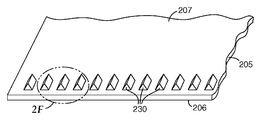
2E and 2F illustrate scale features arranged longitudinally on a web in accordance with an embodiment of the invention.
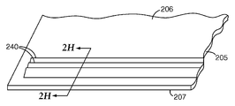
2G and 2H illustrate scale features arranged laterally on a web in accordance with an embodiment of the invention.
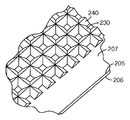
2I illustrates longitudinal and lateral scale features of a checkerboard pattern in accordance with an embodiment of the invention.
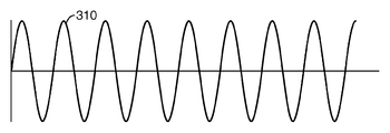
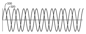
3A is a graph of light intensity at the surface of a photodetector, modulated by scale features in accordance with an embodiment of the invention.
FIG. 3B is a graph of light intensity at the surface of a dual optical sensor, modulated by a scale feature and a scanning reticle to achieve sinusoidal light intensity with a phase difference of about 90 ° in accordance with an embodiment of the invention. .
4A is a flow diagram illustrating a process of indicating substrate location using a TIR scale in accordance with an embodiment of the invention.
4B is a flow diagram illustrating a method of determining coarse web position and fine web position in accordance with an embodiment of the present invention.
5A is an illustration of a roll article including a web having integral scale features in accordance with an embodiment of the present invention.
5B is a view of a portion of a roll article having a unitary scale and comprising a web with pattern features deposited thereon in accordance with an embodiment of the present invention.
5C is an illustration of a scale separated from a web in accordance with an embodiment of the present invention.
6 is a side view of a portion of a roller having a negative TIR feature that can be used to form a TIR scale on a substrate in accordance with an embodiment of the invention.
FIG. 7 illustrates a system for forming a scale comprising TIR prism features on a substrate in accordance with an embodiment of the present invention. FIG.
FIG. 8 illustrates a system for simultaneously forming a first layer of scale and pattern features including TIR prism features on a substrate in accordance with an embodiment of the present invention. FIG.
FIG. 9 illustrates a system for making a double sided web substrate including a feature on opposing surfaces of a web in accordance with an embodiment of the present invention. FIG.
FIG. 10 illustrates first and second patterned rollers that may be used to produce a double sided web substrate including features on opposing surfaces of a web in accordance with an embodiment of the present invention. FIG.
FIG. 11 illustrates a system in which a TIR scale formed in a previous manufacturing step is used to control the position of a substrate during a subsequent manufacturing step in accordance with an embodiment of the present invention.
12 illustrates a scale feature arranged longitudinally on one surface of a web and a second pattern on the back of the web in accordance with an embodiment of the present invention.
While the present invention is subject to various modifications and alternative forms, specific embodiments thereof are shown by way of example in the drawings and will be described in detail. It will be understood, however, that the intention is not to limit the invention to the particular embodiments described. On the contrary, the intention is to cover all modifications, equivalents, and alternatives falling within the scope of the invention as defined by the appended claims.
There is a need for improved methods and systems that exhibit displacement of the substrate. The present invention fulfills these and other needs and provides other advantages over the prior art.
In the following description of the illustrated embodiments, reference is made to the accompanying drawings that form a part hereof, in which is shown by way of illustration various embodiments in which the invention may be practiced. It is to be understood that other embodiments may be utilized and structural changes may be made without departing from the scope of the present invention.
Embodiments of the present invention illustrate scales for determining displacement of substrates or other articles of interest, and methods and systems for making and using the scales. The scale may be used to provide an indication of web translation and / or rotational displacement, and may be employed to determine web position and / or to control the movement of the flexible web. In addition or alternatively to indicating the translational and / or rotational displacement of the web, the scale may also be used to measure various parameters of the web or surrounding environment surrounding the web. For example, as discussed in more detail below, the scale can be used to measure the temperature and / or modulus of the web and / or can be used to measure the web strain. The substrate may be made of a transparent rigid material such as glass or may comprise a transparent flexible stretchable material such as a flexible polymeric web.
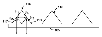
The scale includes a plurality of optical scale features configured as total internal reflection (TIR) prisms. Total internal reflection occurs when the incident angle θ i of light on the prism face is greater than or equal to the critical angle θ c . For incident angles above the critical angle θ c , all incident light is reflected.
1A shows a scale that includes a
The TIR scale feature can be formed in any shape or shape that provides reflection through the TIR. In some embodiments, the TIR scale feature may include a right angle right prism as illustrated in FIG. 1B. In this embodiment, if the angle θ i1 of incident light incident on the
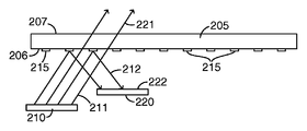
2A-2D are diagrams of systems configured to represent displacement of a substrate using a TIR scale disposed on the substrate. As illustrated in FIGS. 2A and 2B, the system includes a
The system of FIG. 2A illustrates a system representing substrate displacement, operating in reflective mode. In the reflective mode, a
2B illustrates a system representing web position, operating in transmission mode. In this configuration, the
2A and 2B, as the
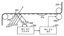
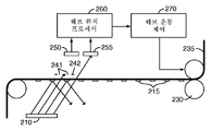
In some embodiments, the analog output signal generated by the photosensor can be used to control the movement of the substrate. For example, the use of TIR scale features disposed on flexible long web substrates is particularly useful for roll-to-roll manufacturing applications. 2C and 2D illustrate a system for controlling web movement when the components used to represent the web position are arranged to operate in reflection mode (FIG. 2C) and transmission mode (FIG. 2D).
The
Output signals generated by
In some embodiments, multiple light sources and / or multiple light sensors may be used to detect translational and / or angular displacement of the web and / or to determine web parameters. Systems using multiple sensor combinations provide signal redundancy, providing a more robust system. In some embodiments, the energy is modulated by more than one scale feature, for example about 3-20 features. The output signal from the sensor can average or otherwise combine the energy modulated by multiple features. Even if a single feature or even several features are damaged or obscured by dust, the averaged output signal is minimally affected.
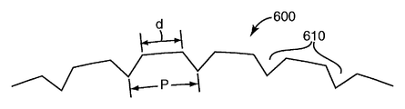
The scale feature may comprise a longitudinally arranged feature, a laterally arranged feature, or a combination of both the longitudinally arranged feature and the laterally arranged feature. As illustrated in FIGS. 2E and 2F, in one embodiment, the set of scale features 230 is a
The scale feature illustrated in FIGS. 2E-2H is a linear triangular prism, which may have a prism pitch and distance between the prisms down to about several micrometers. Convenient dimensions for this type of prism include a prism pitch of about 40 μm and the distance between the prisms of about 20 μm.
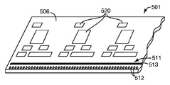
The use of both longitudinal and lateral scale features and compatible light / sensor combinations allows for the display of angular displacements as well as longitudinal and lateral web displacements. 2I illustrates a web in which both longitudinal scale features 230 and lateral scale features 240 are disposed on the
Determination of continuous web position using an integral TIR scale disposed on the web can be employed to control the movement of the web during deposition of pattern features in one or multiple successive fabrication steps. For example, the TIR scale described in connection with the embodiments of the present invention provided herein can be used to indicate continuous web position. Indication of the web location facilitates alignment between multiple layers of pattern features deposited or otherwise formed on the web during the roll-to-roll manufacturing process. The scales described herein are particularly useful for the fabrication of flexible multilayer electronic or optical devices that require multiple deposition steps to form continuous layers of pattern features on the flexible web. TIR scale features may be formed on, for example, flexible polymer webs having a bending radius of less than about 100 mm, less than about 50 mm, less than about 25 mm or even less than about 5 mm. The small bending radius allows the production of TIR scales as roll products.
In addition, the approach described herein can be used to automatically compensate for changes in web strain that commonly occur in web processing applications. For example, in some embodiments, scale features are deposited on a web substantially simultaneously with a layer of web pattern features, such as a first layer of web pattern features used to form a multilayer electronic or optoelectronic device. When scale features and web pattern features are deposited, the pattern features and scale features experience the same amount of web strain. In this configuration, the scale feature can be used to accurately track the position of the first layer web pattern feature regardless of the amount of web strain in subsequent processing. The scale feature can be used to accurately track the lateral position, longitudinal position and / or angular rotation of the first layer web pattern feature regardless of the amount of web strain in subsequent processing.
As the web strain is increased (ie, as the web is stretched further), the scale features are stretched along with corresponding web pattern features formed on the web. This phenomenon allows the scale features used to more accurately track the location of the features deposited on the web. Using the scales described in accordance with various embodiments herein, accurate alignment with web pattern features deposited simultaneously or subsequently may be achieved even when the web is stretched. Further details regarding the use of scale features to indicate the position of the flexible web, aspects of which can be used in connection with embodiments of the present invention, are agent documents filed concurrently with this application and incorporated herein by reference. Provided in a co-owned US patent application identified by number 62854US002.
In addition or alternatively to providing an indication of the translational displacement and / or angular rotation of the web, the scale can also be used to measure various parameters of the web or surrounding environment surrounding the web. For example, as discussed in more detail below, scales can be used to measure the temperature, modulus of elasticity, and / or web strain of a web.
4A is a flow diagram illustrating a process of indicating substrate location using a TIR scale in accordance with an embodiment of the present invention. Light is directed towards the substrate with the TIR scale disposed thereon (step 401). For example, in one implementation, the scale feature can include a series of individual prisms arranged longitudinally on the web. The longitudinally arranged prisms are configured for light modulation that can be measured to determine the longitudinal displacement. In other implementations, the scale feature can include a first set of prisms arranged longitudinally and another set of prisms arranged laterally. The longitudinal prism and the lateral prism are configured to modulate the light for the determination of the longitudinal and lateral displacement of the web, and can also be used to determine the angular rotation of the web.
The TIR feature of the scale modulates the light directed towards the substrate (step 402). The modulated light is detected by the photosensor (step 403) and an output signal indicative of substrate displacement is generated based on the detected light (step 404). By this approach, more than one degree of freedom of the web can be measured. The output signal can provide a longitudinal indication of the web, lateral displacement and / or a continuous indication of each rotation.
As previously discussed with respect to FIG. 3B, the signal used to track the web position may include a sine or cosine signal. Sine or cosine signals advantageously allow for the determination of approximate web positions and fine web positions. 4B is a flow diagram illustrating a method of determining coarse web position and fine web position in accordance with an embodiment of the present invention. Light is directed towards the substrate having the TIR feature disposed thereon (step 410). The TIR feature modulates light directed towards the substrate (step 420). The modulated light is sensed by the photosensor (step 430) and first and second output signals phase shifted by 90 ° are generated (step 440). Web position correction is applied (step 450). The arc tangent of the phase shifted output signal is calculated (step 460) and used to track the coarse and fine positions of the web (step 470).
As previously discussed, the use of flexible long webs with integral scales is particularly advantageous for use in roll-to-roll manufacturing processes. For example, integrated scale can be used to position the web for manufacturing processes that require alignment during successive manufacturing steps, such as in the formation of layered electronic or optical devices. Web positioning using the integrated scales illustrated herein is flexible for low cost electronics, memory, signs, electronic paper, displays including liquid crystals (LCDs) or organic light emitting diodes (OLEDs) or other applications. It can be used in the manufacture of circuits.
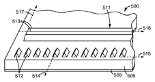
5A illustrates a portion of a
Alternatively, as shown in FIG. 5B, the
In some embodiments, as shown in FIG. 5C,
Scales formed on flexible materials are particularly useful when they are attached to the base substrate. One consideration encountered when attaching the scale to a machine or other substrate is the difference in the coefficient of thermal expansion (CTE) between the substrate and the scale. For example, if a very rigid scale is used, the scale will expand at a different rate than the substrate, so the scale changes by an amount different by (CTE scale -CTE substrate ) * deltaT * scale length. If the scale expands less than the substrate, it is relatively easy to manage because the scale is in tension and will always follow a straight line. However, if the scale expands more than the substrate, the scale will be in a compressed state and additional force is generated that tends to buck the scale (ie, the scale tends to wrinkle out of plane). The compressive force generated is λ (coefficient) * A (area) * strain.
Flexible scales formed according to various embodiments of the present invention have a CTE that is typically about five times higher than the steel scales used, but have a modulus of elasticity that is about 300 times smaller than the steel scales. The net force is about 60 times smaller. Thus, the flexible scale described herein can be bonded to the substrate without significant buckling, allowing the scale to more closely track the position of the substrate.
By using a flexible scale, such as a plastic or polymer scale with a rectangular array of pyramids that allows x / y readings, it is possible to make the flexible scale larger than currently available scales. For example, it is possible to create scales that are several miles long and more than 60 inches wide.
Embodiments described herein include a displacement scale with a TIR scale feature used to represent the displacement of the substrate. These scales can be used to indicate displacement of the substrate and are useful for providing continuous tracking of the longitudinal (web downstream), lateral (web cross) and / or angular displacement of the web. Additionally or alternatively, scale features can be employed to measure various web parameters. In various embodiments, parameters dependent on the dimensional change of the web, such as temperature, strain and / or modulus of elasticity, can be measured using scale features.
In one application, scale features can be used to measure changes in web temperature. Changing web temperature (δT) causes a corresponding dimensional changes to (δL T.). Scale features and sensor circuitry can be used to measure dimensional change δL T. The temperature change δT of the web can be derived from the measured dimensional change.
The scale feature can be used to measure web strain, which is the amount of deformation caused by the force that stretches the web. For example, considering only longitudinal strains, when a web having an initial length L is stretched along its longitudinal ( x ) axis, the web length is from the first length L 1 to the second length L 2 . varies by δL . The linear strain ( ε x ) of the longitudinally elongated web
Scale features arranged in both the longitudinal (x) and lateral (y) directions can be used with compatible energy source / sensor combinations to measure the longitudinal and lateral deformation of the web. These modifications can be used to calculate each strain or shear strain as well as linear strain along the x and y axes.
In one application, the measured strain of the web can be used to calculate the modulus of elasticity. The modulus of elasticity can be calculated as λ = stress / strain. Thus, by using known forces and measuring web strain as described above, the modulus of elasticity of the web can be determined.
TIR scale features may be formed in or on a substrate by various techniques. For example, scale features may be deposited or otherwise formed on a substrate by casting and curing processes. Alternatively, scale features may be formed by embossing, scribing, ablating, printing or other techniques.
Methods of forming a TIR scale on a substrate include the use of a roller that includes a TIR scale feature of a negative scale. For example, the roller may include a negative pattern or other configuration of scale features illustrated in FIGS. 2F-2G. When longitudinal and lateral scale features are used, the rollers may be configured to provide simultaneous formation of longitudinal and lateral scale features.
The roller is held in contact with or in proximity to the substrate and rotated to form a TIR scale feature on the substrate. The material used to form the TIR features can be deposited on the substrate and the rotation of the rollers forms the TIR features in the material on the substrate. Alternatively or additionally, material may be deposited on the rollers and then transferred from the rollers to the substrate to achieve the formation of features. The material may include, for example, a resin such as a UV or thermoset material, a castable polymer or a curable liquid.
In some embodiments, the rollers can further include negative pattern features. When the roller is held in contact with or in close proximity to the substrate, the pattern features are formed simultaneously on the surface of the substrate with the scale features. In another embodiment, first and second rollers are used, where the first roller includes negative scale features and the second roller has negative pattern features. Scale features and pattern features may be formed on the substrate simultaneously or sequentially using the first and second rollers.
In another embodiment, the first roller is used to form scale features and a first set of pattern features on the surface of the substrate. The second roller is used to form a second set of pattern features on the substrate, such as on the opposite surface of the substrate. In this implementation, the scale features can be used to determine web positions to match the first set of pattern features to facilitate formation of the second set of pattern features.
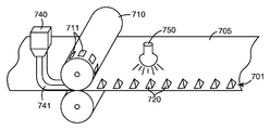
FIG. 6 shows a side view of a portion of
Although not shown, it is noted that the
7 illustrates a system for forming a
In some configurations, the
8 depicts an alternative embodiment of a system for depositing a
In the embodiment shown in FIG. 8,
In some configurations, the materials used to form the TIR scale features and pattern features may be different. In these configurations, separate material distributors and / or curing stations can be used.
9 illustrates an
In the illustrated embodiment, the
In one embodiment, the first extrusion die 916 distributes the first curable
The second
In some configurations, the scale formed by the TIR prism on the first surface of the
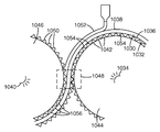
10 provides an enlarged view of the first and second
As the
After the
After the
By supporting the
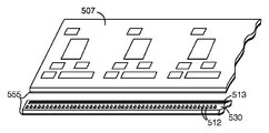
In some embodiments, the TIR scale formed in the previous manufacturing step can be used to control the position of the substrate during subsequent manufacturing steps. Such an embodiment is shown in FIG. 11, where the TIR scale feature and the pattern feature are greatly exaggerated for purposes of illustration. The
After formation of the scale including the
In subsequent processing steps, second pattern features are formed on the web. For example, the second pattern features 1176 may be formed on the surface of the web opposite the surface on which the
The TIR scales described herein can be used to form encoders that provide alignment, web tension control, web steering, and improved switching operations for features formed on both sides of the substrate. TIR scale features can be produced at high speed on a flexible web and do not require the coating to function. Thus, the TIR scale feature can be used to determine web displacement as soon as the feature is formed without a second coating step.
Optional further subsequent processing steps may also be used. Exemplary processing steps may include applying greater tension to the web after curing the material applied to the web. Similarly, another exemplary processing step may include wrapping the roll after curing of the applied feature, and such wrapping may include further stretching the web and the features formed thereon. Such optional processing steps can be beneficial to minimize any shrinkage of the web caused by non-uniform stress applied on the web in the region of the feature. Such shrinkage can lead to the formation of a web buckling or small wrinkles, and optional steps such as those described above can minimize any buckling or wrinkle formation that may occur. Those skilled in the art, having read this specification, will know how to perform such optional processing steps.
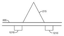
Other methods of minimizing any buckling or wrinkle formation can include the use of secondary structures on the back of the web. An exemplary type of structure would be to compensate or nullify the tendency of a web to buck. An example of such a structure can be seen in FIG. 12. As shown in FIG. 12, the
Those skilled in the art, having read this specification, will understand that such a web comprising back features (as illustrated in FIG. 12) may be manufactured, for example, according to the exemplary method discussed with respect to FIG. 11.
The foregoing descriptions of various embodiments of the present invention have been presented for purposes of illustration and description. It is not intended to be exhaustive or to limit the invention to the precise form disclosed. Many modifications and variations are possible in light of the above teaching. It is intended that the scope of the invention be limited not by this detailed description, but rather by the claims appended hereto.
Claims (28)
One or more rollers having a total internal reflection (TIR) prism feature; And
A drive mechanism configured to rotate the roller such that a displacement scale comprising a TIR prism feature is formed on the substrate
System comprising a.
The curing station includes a heat source.
One or more additional rollers that include negative additional pattern features; And
An additional drive mechanism configured to rotate one or more additional rollers such that additional pattern features are formed on the substrate
The system further includes.
And the scale is configured to match the first set of pattern features to facilitate transferring additional pattern features.
Bringing the substrate into contact with or in proximity to one or more rollers having negative internal total reflection (TIR) prism features; And
Rotating the roller relative to the substrate such that a displacement scale comprising a TIR prism feature is formed on the surface of the substrate
How to include.
Rotating the roller to cause the scale to form comprises rotating the roller to cause the TIR prism features to be formed in the material.
Depositing additional material on opposite surfaces of the web or on one or more additional rollers to form additional web pattern features, wherein the one or more additional rollers have negative additional web pattern features;
Bringing the web into contact with or in proximity to the one or more additional rollers; And
Forming additional web pattern features on opposite surfaces of the web
How to further include.
A roller having an intaglio pattern feature and an arranged internal total reflection (TIR) prism feature, the roller simultaneously comprising scale and pattern features comprising a TIR prism feature on the substrate when the roller is brought into contact with or in proximity to the substrate; Tools configured to form.
Applications Claiming Priority (2)
| Application Number | Priority Date | Filing Date | Title |
|---|---|---|---|
| US94489007P | 2007-06-19 | 2007-06-19 | |
| US60/944,890 | 2007-06-19 |
Related Child Applications (1)
| Application Number | Title | Priority Date | Filing Date |
|---|---|---|---|
| KR1020157005683A Division KR101647265B1 (en) | 2007-06-19 | 2008-06-18 | Systems and methods for fabricating displacement scales |
Publications (1)
| Publication Number | Publication Date |
|---|---|
| KR20100037089A true KR20100037089A (en) | 2010-04-08 |
Family
ID=40156951
Family Applications (2)
| Application Number | Title | Priority Date | Filing Date |
|---|---|---|---|
| KR1020157005683A KR101647265B1 (en) | 2007-06-19 | 2008-06-18 | Systems and methods for fabricating displacement scales |
| KR1020107000369A KR20100037089A (en) | 2007-06-19 | 2008-06-18 | Systems and methods for fabricating displacement scales |
Family Applications Before (1)
| Application Number | Title | Priority Date | Filing Date |
|---|---|---|---|
| KR1020157005683A KR101647265B1 (en) | 2007-06-19 | 2008-06-18 | Systems and methods for fabricating displacement scales |
Country Status (7)
| Country | Link |
|---|---|
| US (1) | US9513412B2 (en) |
| EP (1) | EP2162705A4 (en) |
| JP (1) | JP2010530543A (en) |
| KR (2) | KR101647265B1 (en) |
| CN (1) | CN101688794B (en) |
| BR (1) | BRPI0811666A2 (en) |
| WO (1) | WO2008157588A2 (en) |
Families Citing this family (44)
| Publication number | Priority date | Publication date | Assignee | Title |
|---|---|---|---|---|
| EP2165162A2 (en) * | 2007-06-19 | 2010-03-24 | 3M Innovative Properties Company | Total internal reflection displacement scale |
| CN102317882B (en) | 2008-12-29 | 2015-04-22 | 3M创新有限公司 | Phase-locked web position signal using web fiducials |
| KR101578259B1 (en) | 2008-12-30 | 2015-12-16 | 쓰리엠 이노베이티브 프로퍼티즈 컴파니 | Apparatus and method for making fiducials on a substrate |
| JP5623786B2 (en) | 2009-05-22 | 2014-11-12 | 三星ディスプレイ株式會社Samsung Display Co.,Ltd. | Thin film deposition equipment |
| JP5620146B2 (en) | 2009-05-22 | 2014-11-05 | 三星ディスプレイ株式會社Samsung Display Co.,Ltd. | Thin film deposition equipment |
| US8882920B2 (en) | 2009-06-05 | 2014-11-11 | Samsung Display Co., Ltd. | Thin film deposition apparatus |
| US8882921B2 (en) * | 2009-06-08 | 2014-11-11 | Samsung Display Co., Ltd. | Thin film deposition apparatus |
| KR101117719B1 (en) * | 2009-06-24 | 2012-03-08 | 삼성모바일디스플레이주식회사 | Apparatus for thin layer deposition |
| JP5328726B2 (en) | 2009-08-25 | 2013-10-30 | 三星ディスプレイ株式會社 | Thin film deposition apparatus and organic light emitting display device manufacturing method using the same |
| JP5677785B2 (en) | 2009-08-27 | 2015-02-25 | 三星ディスプレイ株式會社Samsung Display Co.,Ltd. | Thin film deposition apparatus and organic light emitting display device manufacturing method using the same |
| US8696815B2 (en) * | 2009-09-01 | 2014-04-15 | Samsung Display Co., Ltd. | Thin film deposition apparatus |
| WO2011053419A2 (en) * | 2009-09-29 | 2011-05-05 | 3M Innovative Properties Company | Optically transmissive substrate having a fiducial mark and methods of aligning optically transmissive substrates |
| US8876975B2 (en) | 2009-10-19 | 2014-11-04 | Samsung Display Co., Ltd. | Thin film deposition apparatus |
| KR101084184B1 (en) | 2010-01-11 | 2011-11-17 | 삼성모바일디스플레이주식회사 | Apparatus for thin layer deposition |
| KR101174875B1 (en) | 2010-01-14 | 2012-08-17 | 삼성디스플레이 주식회사 | Apparatus for thin layer deposition, method for manufacturing of organic light emitting display apparatus using the same, and organic light emitting display apparatus manufactured by the method |
| KR101193186B1 (en) * | 2010-02-01 | 2012-10-19 | 삼성디스플레이 주식회사 | Apparatus for thin layer deposition, method for manufacturing of organic light emitting display apparatus using the same, and organic light emitting display apparatus manufactured by the method |
| KR101156441B1 (en) | 2010-03-11 | 2012-06-18 | 삼성모바일디스플레이주식회사 | Apparatus for thin layer deposition |
| KR101202348B1 (en) | 2010-04-06 | 2012-11-16 | 삼성디스플레이 주식회사 | Apparatus for thin layer deposition and method for manufacturing of organic light emitting display apparatus using the same |
| US8894458B2 (en) | 2010-04-28 | 2014-11-25 | Samsung Display Co., Ltd. | Thin film deposition apparatus, method of manufacturing organic light-emitting display device by using the apparatus, and organic light-emitting display device manufactured by using the method |
| KR101223723B1 (en) | 2010-07-07 | 2013-01-18 | 삼성디스플레이 주식회사 | Apparatus for thin layer deposition, method for manufacturing of organic light emitting display apparatus using the same, and organic light emitting display apparatus manufactured by the method |
| KR101146997B1 (en) * | 2010-07-12 | 2012-05-23 | 삼성모바일디스플레이주식회사 | A tension apparatus for patterning slit sheet |
| KR101673017B1 (en) | 2010-07-30 | 2016-11-07 | 삼성디스플레이 주식회사 | Apparatus for thin layer deposition and method for manufacturing of organic light emitting display apparatus using the same |
| KR101738531B1 (en) | 2010-10-22 | 2017-05-23 | 삼성디스플레이 주식회사 | Method for manufacturing of organic light emitting display apparatus, and organic light emitting display apparatus manufactured by the method |
| KR101723506B1 (en) | 2010-10-22 | 2017-04-19 | 삼성디스플레이 주식회사 | Apparatus for organic layer deposition and method for manufacturing of organic light emitting display apparatus using the same |
| KR20120045865A (en) | 2010-11-01 | 2012-05-09 | 삼성모바일디스플레이주식회사 | Apparatus for organic layer deposition |
| KR20120065789A (en) | 2010-12-13 | 2012-06-21 | 삼성모바일디스플레이주식회사 | Apparatus for organic layer deposition |
| KR101760897B1 (en) | 2011-01-12 | 2017-07-25 | 삼성디스플레이 주식회사 | Deposition source and apparatus for organic layer deposition having the same |
| KR101852517B1 (en) | 2011-05-25 | 2018-04-27 | 삼성디스플레이 주식회사 | Apparatus for organic layer deposition and method for manufacturing of organic light emitting display apparatus using the same |
| KR101840654B1 (en) | 2011-05-25 | 2018-03-22 | 삼성디스플레이 주식회사 | Apparatus for organic layer deposition and method for manufacturing of organic light emitting display apparatus using the same |
| KR101857249B1 (en) | 2011-05-27 | 2018-05-14 | 삼성디스플레이 주식회사 | Patterning slit sheet assembly, apparatus for organic layer deposition, method for manufacturing organic light emitting display apparatus and organic light emitting display apparatus |
| KR101826068B1 (en) | 2011-07-04 | 2018-02-07 | 삼성디스플레이 주식회사 | Apparatus for thin layer deposition |
| BR112014014108A2 (en) | 2011-12-15 | 2017-06-13 | 3M Innovative Properties Co | apparatus for guiding a moving blanket |
| WO2014088939A1 (en) | 2012-12-06 | 2014-06-12 | 3M Innovative Properties Company | Discrete coating of liquid on a liquid-coated substrate and use in forming laminates |
| US9738816B2 (en) | 2012-12-06 | 2017-08-22 | 3M Innovative Properties Company | Precision coating of viscous liquids and use in forming laminates |
| EP2934768B1 (en) * | 2012-12-20 | 2017-08-23 | 3M Innovative Properties Company | Printing of multiple inks to achieve precision registration during subsequent processing |
| KR102037376B1 (en) | 2013-04-18 | 2019-10-29 | 삼성디스플레이 주식회사 | Patterning slit sheet, deposition apparatus comprising the same, method for manufacturing organic light emitting display apparatus using the same, organic light emitting display apparatus manufacture by the method |
| TW201441050A (en) * | 2013-04-25 | 2014-11-01 | Hon Hai Prec Ind Co Ltd | Manufacturing apparatus and method for optical compound film |
| KR102182751B1 (en) | 2013-08-28 | 2020-11-25 | 쓰리엠 이노베이티브 프로퍼티즈 캄파니 | Electronic assembly with fiducial marks for precision registration during subsequent processing steps |
| KR102399443B1 (en) * | 2014-06-20 | 2022-05-19 | 쓰리엠 이노베이티브 프로퍼티즈 캄파니 | Printing of multiple inks to achieve precision registration during subsequent processing |
| US20180118982A1 (en) | 2015-05-05 | 2018-05-03 | 3M Innovative Properties Company | Warm melt optically clear adhesives and their use for display assembly |
| US20200045955A1 (en) * | 2017-01-31 | 2020-02-13 | Saraya Co., Ltd. | Cell cryopreservation composition and cryopreservation method |
| CN207209309U8 (en) * | 2017-09-29 | 2018-09-07 | 京东方科技集团股份有限公司 | Backlight position correction apparatus |
| US20210178622A1 (en) | 2017-10-24 | 2021-06-17 | 3M Innovative Properties Company | Method and apparatus for generating fiducial via die cutting |
| JP2019082373A (en) * | 2017-10-30 | 2019-05-30 | セイコーエプソン株式会社 | Optical scale, encoder, robot, electronic component conveying device, printer and projector |
Family Cites Families (88)
| Publication number | Priority date | Publication date | Assignee | Title |
|---|---|---|---|---|
| US6087A (en) * | 1849-02-06 | Plate for boiler-holes and tops of stoves | ||
| US1898723A (en) | 1930-05-15 | 1933-02-21 | Package Machinery Co | Method and apparatus for registering printed webs of paper |
| US3570735A (en) | 1968-11-18 | 1971-03-16 | Gpe Controls Inc | Method and apparatus of guiding moving webs |
| US3615048A (en) | 1969-04-03 | 1971-10-26 | Martin Automatic Inc | Apparatus for adjusting the lateral position of a continuous moving web |
| US3667031A (en) | 1970-08-18 | 1972-05-30 | Massachusetts Inst Technology | Phase-locked resolver tracking system |
| US4010463A (en) | 1975-04-21 | 1977-03-01 | The United States Of America As Represented By The Secretary Of The Air Force | Phase locked loop resolver to digital converter |
| DD123663A1 (en) | 1975-05-12 | 1977-01-12 | ||
| US4202600A (en) * | 1978-04-24 | 1980-05-13 | Avery International Corporation | Diced retroreflective sheeting |
| CA1127259A (en) | 1978-10-19 | 1982-07-06 | Jean Burtin | Method and device for inspecting a moving sheet material for streaklike defects |
| DE2851894A1 (en) | 1978-11-30 | 1980-06-12 | Agfa Gevaert Ag | DEVICE FOR SEPARATING PRE-PERFORATED TAPES, PREFERABLY CONTINUOUS BAGS |
| GB2065871A (en) | 1979-12-17 | 1981-07-01 | Crosfield Electronics Ltd | Web register control |
| DE3006072C2 (en) * | 1980-02-19 | 1984-11-29 | Erwin Sick Gmbh Optik-Elektronik, 7808 Waldkirch | Defect detection device for material webs |
| US4945252A (en) | 1980-07-07 | 1990-07-31 | Automated Packaging Systems, Inc. | Continuous web registration |
| US4401893A (en) | 1981-07-29 | 1983-08-30 | Intec Corporation | Method and apparatus for optically inspecting a moving web of glass |
| JPS5990114A (en) | 1982-11-15 | 1984-05-24 | Toshiba Mach Co Ltd | Positioning device using resolver |
| US4618518A (en) | 1984-08-10 | 1986-10-21 | Amerace Corporation | Retroreflective sheeting and methods for making same |
| US4610739A (en) | 1984-11-02 | 1986-09-09 | Adolph Coors Company | Method and device for providing longitudinal and lateral stretch control in laminated webs |
| JPS625127A (en) | 1985-07-01 | 1987-01-12 | Canon Inc | Optical scale |
| JPS62111860A (en) | 1985-11-08 | 1987-05-22 | Matsushita Graphic Commun Syst Inc | Device for detecting position of running sheet |
| US4697485A (en) | 1986-04-16 | 1987-10-06 | Preco Industries, Inc. | Die press having 3-axis registration system operable during material advancement |
| GB2195179B (en) | 1986-09-11 | 1991-05-15 | Synergy Computer Graphics | Registration system for a moving substrate |
| JPH0237963A (en) | 1988-04-28 | 1990-02-07 | Toshiba Corp | Electrical heating member |
| US4893135A (en) | 1988-09-23 | 1990-01-09 | Eastman Kodak Company | Laser printer with position registration enhancement |
| EP0392085B1 (en) | 1989-04-12 | 1992-04-15 | Landis & Gyr Betriebs AG | Device for measuring the track-deviation of a moving foil web |
| JPH04208810A (en) * | 1990-12-03 | 1992-07-30 | Omron Corp | Apparatus for outputting displacement signal |
| JP2586244B2 (en) | 1991-07-05 | 1997-02-26 | 東洋製罐株式会社 | Metal web position detection method |
| US5355154A (en) | 1992-12-23 | 1994-10-11 | Xerox Corporation | Electronic color printers multiple-pass image self-registration |
| EP0606731B1 (en) | 1992-12-25 | 1997-08-06 | ISHIDA CO., Ltd. | Apparatus for correcting zigzag motion of an elongated travelling web |
| US5450116A (en) | 1993-09-14 | 1995-09-12 | P-M Acquisition Corp. | Apparatus for generating a spreading information tape |
| US7171016B1 (en) | 1993-11-18 | 2007-01-30 | Digimarc Corporation | Method for monitoring internet dissemination of image, video and/or audio files |
| US5448020A (en) | 1993-12-17 | 1995-09-05 | Pendse; Rajendra D. | System and method for forming a controlled impedance flex circuit |
| US5759455A (en) * | 1994-07-08 | 1998-06-02 | Canon Kabushiki Kaisha | Roller-shaped stamper for fabricating optical scales |
| JP3466718B2 (en) * | 1994-07-08 | 2003-11-17 | キヤノン株式会社 | Optical scale molding die and method of manufacturing optical scale |
| US5979732A (en) | 1994-11-04 | 1999-11-09 | Roll Systems, Inc. | Method and apparatus for pinless feeding of web to a utilization device |
| JPH08229955A (en) | 1995-02-24 | 1996-09-10 | Canon Inc | Master mold for molding optical scale, production thereof, production of stamper for molding optical scale and production of optical scale |
| US5868074A (en) | 1995-05-08 | 1999-02-09 | Flex Products, Inc. | Laser imageable direct-write printing member |
| US5778724A (en) | 1995-09-07 | 1998-07-14 | Minnesota Mining & Mfg | Method and device for monitoring web bagginess |
| US5760414A (en) | 1995-12-19 | 1998-06-02 | Monarch Marking Systems, Inc. | Web of record members and method of and apparatus for making same and system for detecting indicia |
| KR970062816A (en) | 1996-02-13 | 1997-09-12 | 박병재 | Engine room irradiation device using head lamp |
| US5870203A (en) | 1996-03-15 | 1999-02-09 | Sony Corporation | Adaptive lighting control apparatus for illuminating a variable-speed web for inspection |
| US6130777A (en) * | 1996-05-16 | 2000-10-10 | Dai Nippon Printing Co., Ltd. | Lenticular lens sheet with both a base sheet having lenticular elements and a surface diffusing part having elements of elementary shape smaller than lenticular elements |
| JPH10132612A (en) | 1996-10-28 | 1998-05-22 | Mitsutoyo Corp | Optical displacement detecting device |
| DE19721170A1 (en) * | 1997-05-21 | 1998-11-26 | Emtec Magnetics Gmbh | Method and device for producing a film or a layer with a surface structure on both sides |
| DE19754776A1 (en) | 1997-11-28 | 1999-06-02 | Ralf Dr Paugstadt | Security marking system e.g. to prevent fraud, counterfeiting and pilfering |
| US6036322A (en) * | 1997-12-01 | 2000-03-14 | Reflexite Corporation | Multi-orientation retroreflective structure |
| JPH11167165A (en) | 1997-12-03 | 1999-06-22 | Fuji Photo Film Co Ltd | Method for aligning frame detection part of microfilm retrieving device and microfilm for alignment |
| US6087655A (en) | 1998-05-19 | 2000-07-11 | Kobrin; Boris | Fiber grating encoders and methods for fabricating the same |
| US6164201A (en) | 1998-09-11 | 2000-12-26 | Heidelberger Druckmachinen Ag | Method and apparatus for web steering |
| EP1003078A3 (en) | 1998-11-17 | 2001-11-07 | Corning Incorporated | Replicating a nanoscale pattern |
| US6666075B2 (en) | 1999-02-05 | 2003-12-23 | Xidex Corporation | System and method of multi-dimensional force sensing for scanning probe microscopy |
| US6322236B1 (en) * | 1999-02-09 | 2001-11-27 | 3M Innovative Properties Company | Optical film with defect-reducing surface and method for making same |
| US6273313B1 (en) | 1999-06-02 | 2001-08-14 | The Proctor & Gamble Company | Process and apparatus for controlling the registration of converting operations with prints on a web |
| US6521905B1 (en) | 1999-09-22 | 2003-02-18 | Nexpress Solutions Llc | Method and device for detecting the position of a transparent moving conveyor belt |
| JP4444469B2 (en) | 2000-08-07 | 2010-03-31 | 株式会社ミツトヨ | Optical displacement measuring device |
| US7230764B2 (en) * | 2000-08-18 | 2007-06-12 | Reflexite Corporation | Differentially-cured materials and process for forming same |
| CN2447719Y (en) | 2000-10-30 | 2001-09-12 | 中南大学 | Linear displacement transducer |
| JP4280447B2 (en) | 2001-02-20 | 2009-06-17 | キヤノン株式会社 | Reflection scale and displacement detection device using the same |
| US6505906B1 (en) | 2001-12-28 | 2003-01-14 | Phogenix Imaging, Llc | Method of exercising nozzles of an inkjet printer and article |
| ITTO20011045A1 (en) | 2001-11-02 | 2003-05-02 | Tetra Laval Holdings E Finance | SHEET MATERIAL FOR THE PRODUCTION OF PACKAGES OF FOOD PRODUCTS, AND PACKAGES MADE WITH SUCH MATERIAL. |
| US6842602B2 (en) | 2002-03-22 | 2005-01-11 | Ricoh Company, Ltd. | Drive control device and image forming apparatus including the same |
| JP4208483B2 (en) | 2002-05-21 | 2009-01-14 | キヤノン株式会社 | Optical encoder |
| US6999007B2 (en) | 2003-05-15 | 2006-02-14 | Delphi Technologies, Inc. | Linear position sensor |
| US20040234724A1 (en) * | 2003-05-22 | 2004-11-25 | Eastman Kodak Company | Immisible polymer filled optical elements |
| US6819544B1 (en) * | 2003-05-30 | 2004-11-16 | Medtronic, Inc. | Dual-anode electrolytic capacitor for use in an implantable medical device |
| US7025498B2 (en) | 2003-05-30 | 2006-04-11 | Asml Holding N.V. | System and method of measuring thermal expansion |
| JP4428948B2 (en) | 2003-06-30 | 2010-03-10 | キヤノン株式会社 | Optical encoder |
| JP4755400B2 (en) | 2003-08-29 | 2011-08-24 | 株式会社リコー | Endless moving member driving device, image forming apparatus, photoreceptor driving device, and endless moving member deterioration warning method |
| US20050231809A1 (en) * | 2003-09-09 | 2005-10-20 | Carlson Daniel H | Microreplicated polarizing article |
| US7121496B2 (en) | 2003-10-23 | 2006-10-17 | Hewlett-Packard Development Company, L.P. | Method and system for correcting web deformation during a roll-to-roll process |
| US7296717B2 (en) | 2003-11-21 | 2007-11-20 | 3M Innovative Properties Company | Method and apparatus for controlling a moving web |
| JP4292979B2 (en) | 2003-12-18 | 2009-07-08 | 株式会社村田製作所 | Position recognition method and position recognition apparatus for conveyed object |
| KR20080019729A (en) | 2004-04-02 | 2008-03-04 | 실버브룩 리서치 피티와이 리미티드 | Monolithic integrated circuit |
| US7623699B2 (en) | 2004-04-19 | 2009-11-24 | 3M Innovative Properties Company | Apparatus and method for the automated marking of defects on webs of material |
| JP2005337843A (en) | 2004-05-26 | 2005-12-08 | Canon Inc | Optical encoder |
| JP4498024B2 (en) | 2004-06-15 | 2010-07-07 | キヤノン株式会社 | Optical encoder |
| JP2006017615A (en) | 2004-07-02 | 2006-01-19 | Ricoh Co Ltd | Mark detector, rotor drive unit, and image forming apparatus |
| JP2006272883A (en) | 2005-03-30 | 2006-10-12 | Nissha Printing Co Ltd | Apparatus and method of transfer molding |
| US20060174992A1 (en) | 2005-02-09 | 2006-08-10 | Brost Randolph C | Web stabilization for accurate pattern registration |
| JP4861400B2 (en) | 2005-03-09 | 2012-01-25 | スリーエム イノベイティブ プロパティズ カンパニー | Apparatus and method for making aligned double-sided patterned webs |
| JP4803641B2 (en) | 2005-05-12 | 2011-10-26 | オリンパス株式会社 | Optical encoder |
| ATE378574T1 (en) | 2005-07-01 | 2007-11-15 | Texmag Gmbh Vertriebsges | METHOD FOR DETECTING A MARKING ON A RUNNING WEB |
| WO2007027757A2 (en) | 2005-08-30 | 2007-03-08 | Georgia Tech Research Corporation | Direct write nanolithography using heated tip |
| JP2009511276A (en) * | 2005-10-11 | 2009-03-19 | ジーエスアイ・グループ・コーポレーション | Optical measuring scale and its laser manufacturing method |
| JP2007150258A (en) | 2005-10-27 | 2007-06-14 | Seiko Epson Corp | Pattern forming method, film structure, electro-optic device, and electronic apparatus |
| US20070138153A1 (en) | 2005-12-20 | 2007-06-21 | Redman Dean E | Wide web laser ablation |
| WO2008021226A1 (en) | 2006-08-12 | 2008-02-21 | Philometron, Inc. | Platform for detection of tissue structure change |
| JP4928206B2 (en) | 2006-09-22 | 2012-05-09 | キヤノン株式会社 | Encoder |
| JP4260870B1 (en) | 2008-03-05 | 2009-04-30 | 太洋電機産業株式会社 | Register mark detection device |
-
2008
- 2008-06-18 US US12/664,561 patent/US9513412B2/en active Active
- 2008-06-18 KR KR1020157005683A patent/KR101647265B1/en active IP Right Grant
- 2008-06-18 EP EP08771339.2A patent/EP2162705A4/en not_active Withdrawn
- 2008-06-18 JP JP2010513374A patent/JP2010530543A/en active Pending
- 2008-06-18 BR BRPI0811666-0A2A patent/BRPI0811666A2/en not_active IP Right Cessation
- 2008-06-18 CN CN2008800212417A patent/CN101688794B/en not_active Expired - Fee Related
- 2008-06-18 WO PCT/US2008/067311 patent/WO2008157588A2/en active Application Filing
- 2008-06-18 KR KR1020107000369A patent/KR20100037089A/en active IP Right Grant
Also Published As
| Publication number | Publication date |
|---|---|
| EP2162705A4 (en) | 2014-02-19 |
| US20100196607A1 (en) | 2010-08-05 |
| WO2008157588A3 (en) | 2009-03-12 |
| JP2010530543A (en) | 2010-09-09 |
| WO2008157588A2 (en) | 2008-12-24 |
| KR20150034814A (en) | 2015-04-03 |
| CN101688794A (en) | 2010-03-31 |
| US9513412B2 (en) | 2016-12-06 |
| CN101688794B (en) | 2012-12-12 |
| KR101647265B1 (en) | 2016-08-09 |
| BRPI0811666A2 (en) | 2015-02-10 |
| EP2162705A2 (en) | 2010-03-17 |
Similar Documents
| Publication | Publication Date | Title |
|---|---|---|
| KR101647265B1 (en) | Systems and methods for fabricating displacement scales | |
| KR20100049540A (en) | Total internal reflection displacement scale | |
| EP2167411B1 (en) | Systems and methods for indicating the position of a web | |
| JP5465489B2 (en) | High-speed fine substrate alignment equipment in roll-to-roll system | |
| JP5467531B2 (en) | Display element manufacturing method and manufacturing apparatus | |
| JP2012084732A (en) | Imprint method and device | |
| CN101796216B (en) | Production equipment and method of thin-film laminate | |
| CN101009218A (en) | Pattern forming method and pattern forming system | |
| KR20130082499A (en) | Device and method for reducing a wedge error | |
| US20110084417A1 (en) | Large area linear array nanoimprinting | |
| WO2013035696A1 (en) | Substrate transfer apparatus and substrate processing apparatus | |
| EP2552598B1 (en) | Precision control of web material having micro-replicated lens array | |
| JP2011189610A (en) | Transfer device | |
| JP2008045931A (en) | Method of manufacturing scale of optical type encoder | |
| JP2010217207A5 (en) | ||
| EP4164971A1 (en) | Systems and methods for measuring tension distribution in webs of roll-to-roll processes | |
| KR20120013127A (en) | Method and apparatus for providing precise printing using linear encoder | |
| KR101091960B1 (en) | Apparatus and fabrication method for a roll stamp | |
| KR101602140B1 (en) | Method and apparatus for precision control and measurement of lateral web position using optical sensor, and method and apparatus for printing using the same |
Legal Events
| Date | Code | Title | Description |
|---|---|---|---|
| A201 | Request for examination | ||
| AMND | Amendment | ||
| E902 | Notification of reason for refusal | ||
| AMND | Amendment | ||
| E601 | Decision to refuse application | ||
| A107 | Divisional application of patent | ||
| AMND | Amendment | ||
| J201 | Request for trial against refusal decision | ||
| E902 | Notification of reason for refusal | ||
| B601 | Maintenance of original decision after re-examination before a trial | ||
| J301 | Trial decision |
Free format text: TRIAL NUMBER: 2015101001224; TRIAL DECISION FOR APPEAL AGAINST DECISION TO DECLINE REFUSAL REQUESTED 20150304 Effective date: 20170331 |
|
| S901 | Examination by remand of revocation | ||
| GRNO | Decision to grant (after opposition) |