KR20100015853A - Wind turbine blade position determination system - Google Patents
Wind turbine blade position determination system Download PDFInfo
- Publication number
- KR20100015853A KR20100015853A KR1020097022214A KR20097022214A KR20100015853A KR 20100015853 A KR20100015853 A KR 20100015853A KR 1020097022214 A KR1020097022214 A KR 1020097022214A KR 20097022214 A KR20097022214 A KR 20097022214A KR 20100015853 A KR20100015853 A KR 20100015853A
- Authority
- KR
- South Korea
- Prior art keywords
- wind turbine
- signal
- turbine blade
- transmitter
- transmitter device
- Prior art date
Links
- 238000000034 method Methods 0.000 claims description 48
- 230000005540 biological transmission Effects 0.000 claims description 19
- 230000008054 signal transmission Effects 0.000 abstract 1
- 230000008569 process Effects 0.000 description 11
- 238000012545 processing Methods 0.000 description 4
- 238000009434 installation Methods 0.000 description 3
- 238000005259 measurement Methods 0.000 description 3
- 238000012544 monitoring process Methods 0.000 description 3
- 238000005452 bending Methods 0.000 description 2
- 230000008901 benefit Effects 0.000 description 2
- 238000004891 communication Methods 0.000 description 2
- 238000012423 maintenance Methods 0.000 description 2
- 238000004519 manufacturing process Methods 0.000 description 2
- 239000003990 capacitor Substances 0.000 description 1
- 230000001934 delay Effects 0.000 description 1
- 230000001419 dependent effect Effects 0.000 description 1
- 238000010586 diagram Methods 0.000 description 1
- 238000004146 energy storage Methods 0.000 description 1
- 230000007246 mechanism Effects 0.000 description 1
- 230000003287 optical effect Effects 0.000 description 1
- 230000004044 response Effects 0.000 description 1
- 230000001360 synchronised effect Effects 0.000 description 1
Images


Classifications
-
- F—MECHANICAL ENGINEERING; LIGHTING; HEATING; WEAPONS; BLASTING
- F03—MACHINES OR ENGINES FOR LIQUIDS; WIND, SPRING, OR WEIGHT MOTORS; PRODUCING MECHANICAL POWER OR A REACTIVE PROPULSIVE THRUST, NOT OTHERWISE PROVIDED FOR
- F03D—WIND MOTORS
- F03D7/00—Controlling wind motors
- F03D7/02—Controlling wind motors the wind motors having rotation axis substantially parallel to the air flow entering the rotor
- F03D7/04—Automatic control; Regulation
- F03D7/042—Automatic control; Regulation by means of an electrical or electronic controller
- F03D7/047—Automatic control; Regulation by means of an electrical or electronic controller characterised by the controller architecture, e.g. multiple processors or data communications
-
- F—MECHANICAL ENGINEERING; LIGHTING; HEATING; WEAPONS; BLASTING
- F03—MACHINES OR ENGINES FOR LIQUIDS; WIND, SPRING, OR WEIGHT MOTORS; PRODUCING MECHANICAL POWER OR A REACTIVE PROPULSIVE THRUST, NOT OTHERWISE PROVIDED FOR
- F03D—WIND MOTORS
- F03D7/00—Controlling wind motors
- F03D7/02—Controlling wind motors the wind motors having rotation axis substantially parallel to the air flow entering the rotor
- F03D7/04—Automatic control; Regulation
-
- F—MECHANICAL ENGINEERING; LIGHTING; HEATING; WEAPONS; BLASTING
- F03—MACHINES OR ENGINES FOR LIQUIDS; WIND, SPRING, OR WEIGHT MOTORS; PRODUCING MECHANICAL POWER OR A REACTIVE PROPULSIVE THRUST, NOT OTHERWISE PROVIDED FOR
- F03D—WIND MOTORS
- F03D17/00—Monitoring or testing of wind motors, e.g. diagnostics
-
- F—MECHANICAL ENGINEERING; LIGHTING; HEATING; WEAPONS; BLASTING
- F05—INDEXING SCHEMES RELATING TO ENGINES OR PUMPS IN VARIOUS SUBCLASSES OF CLASSES F01-F04
- F05B—INDEXING SCHEME RELATING TO WIND, SPRING, WEIGHT, INERTIA OR LIKE MOTORS, TO MACHINES OR ENGINES FOR LIQUIDS COVERED BY SUBCLASSES F03B, F03D AND F03G
- F05B2270/00—Control
- F05B2270/30—Control parameters, e.g. input parameters
- F05B2270/326—Rotor angle
-
- F—MECHANICAL ENGINEERING; LIGHTING; HEATING; WEAPONS; BLASTING
- F05—INDEXING SCHEMES RELATING TO ENGINES OR PUMPS IN VARIOUS SUBCLASSES OF CLASSES F01-F04
- F05B—INDEXING SCHEME RELATING TO WIND, SPRING, WEIGHT, INERTIA OR LIKE MOTORS, TO MACHINES OR ENGINES FOR LIQUIDS COVERED BY SUBCLASSES F03B, F03D AND F03G
- F05B2270/00—Control
- F05B2270/30—Control parameters, e.g. input parameters
- F05B2270/33—Proximity of blade to tower
-
- F—MECHANICAL ENGINEERING; LIGHTING; HEATING; WEAPONS; BLASTING
- F05—INDEXING SCHEMES RELATING TO ENGINES OR PUMPS IN VARIOUS SUBCLASSES OF CLASSES F01-F04
- F05B—INDEXING SCHEME RELATING TO WIND, SPRING, WEIGHT, INERTIA OR LIKE MOTORS, TO MACHINES OR ENGINES FOR LIQUIDS COVERED BY SUBCLASSES F03B, F03D AND F03G
- F05B2270/00—Control
- F05B2270/80—Devices generating input signals, e.g. transducers, sensors, cameras or strain gauges
-
- Y—GENERAL TAGGING OF NEW TECHNOLOGICAL DEVELOPMENTS; GENERAL TAGGING OF CROSS-SECTIONAL TECHNOLOGIES SPANNING OVER SEVERAL SECTIONS OF THE IPC; TECHNICAL SUBJECTS COVERED BY FORMER USPC CROSS-REFERENCE ART COLLECTIONS [XRACs] AND DIGESTS
- Y02—TECHNOLOGIES OR APPLICATIONS FOR MITIGATION OR ADAPTATION AGAINST CLIMATE CHANGE
- Y02E—REDUCTION OF GREENHOUSE GAS [GHG] EMISSIONS, RELATED TO ENERGY GENERATION, TRANSMISSION OR DISTRIBUTION
- Y02E10/00—Energy generation through renewable energy sources
- Y02E10/70—Wind energy
- Y02E10/72—Wind turbines with rotation axis in wind direction
Abstract
Description
본 발명은 풍력 터빈의 블레이드 위치를 판정하는 시스템에 관한 것이다.The present invention relates to a system for determining the blade position of a wind turbine.
풍력 터빈의 작동을 최적화시키는 것과 관련하여, 오차를 예측하기 위하여 그리고 풍력 터빈 발전기의 에너지 생산을 최적화시키기 위하여 많은 감시 기술들이 공개되어 있다.With regard to optimizing the operation of wind turbines, many monitoring techniques are disclosed to predict errors and to optimize the energy production of wind turbine generators.
국제특허공보 WO 2005/068834 는, 세 개의 GPS 위성들로부터 신호를 수신하여 위치가 확인될 수 있도록 하는 GPS 수신기들일 수 있는, 위치 표시기(indicator)들에 의하여 풍력 터빈의 블레이드들 상에 놓여진 위치 표시기들의 위치를 판정하기 위한 방법에 관한 것이다. 풍력 터빈에 그리고/또는 풍력 터빈 주위에 있는 고정된 위치에 배치된 송신기(transmitter)들과 같은 국지적 송신기들로부터의 신호에 기반하여 위치가 판정될 수 있다.International patent publication WO 2005/068834 is a position indicator placed on the blades of a wind turbine by position indicators, which can be GPS receivers that receive a signal from three GPS satellites and allow position to be identified. A method for determining the location of the field. The location may be determined based on a signal from local transmitters, such as transmitters disposed in a fixed position at and / or around the wind turbine.
종래기술과 관련된 문제점은, GPS 수신기들이 블레이드에 장착되어야 하고, 따라서 장착과 유지보수가 상당히 복잡하며 비용이 많이 소요된다는 것이다. 전술된 종래기술의 다른 문제점은, 블레이드의 블레이드 부분들 또는 블레이드의 상대 위치나 절대 위치를 판정하기 위하여는, 블레이드에서 데이터 및/또는 신호의 처리 가 수행되어야 할 것을 필요로 한다. 블레이드에 있는 GPS 수신기와 같은 상대적으로 민감한 전자기기의 장착에 관련된 다른 문제점은, 장비가 매우 튼튼해야 할 필요가 있다는 것인데, 예를 들어 상대적으로 큰 온도차이 및 블레이드의 진동 및 회전에 의하여 유발되는 기계적 스트레스에 대해 저항성이 있어야 한다는 것이다.A problem associated with the prior art is that the GPS receivers must be mounted on the blades, thus the installation and maintenance are quite complicated and expensive. Another problem of the prior art described above requires that processing of data and / or signals at the blades must be performed in order to determine the blade portions of the blade or the relative or absolute position of the blade. Another problem associated with the installation of relatively sensitive electronics, such as GPS receivers in the blade, is that the equipment needs to be very robust, for example mechanically caused by relatively large temperature differences and blade vibration and rotation. It must be resistant to stress.
본 발명은 신호의 무선 송수신에 의하여 풍력 터빈 블레이드의 적어도 일부분의 위치를 판정하기 위한 시스템에 관한 것인데, 이 시스템은:The present invention relates to a system for determining the position of at least a portion of a wind turbine blade by wireless transmission and reception of a signal, the system comprising:
풍력 터빈 블레이드에 부착된 송신기 장치;A transmitter device attached to the wind turbine blades;
수신 장치; 및A receiving device; And
적어도 하나의 위치 계산 컴퓨터;를 포함하고,At least one position calculation computer;
상기 신호는 상기 적어도 하나의 송신기 장치로부터 상기 수신 장치로 무선으로 송신되고, 상기 위치 계산 컴퓨터는 상기 수신 장치에 의하여 수신된 상기 신호에 기초하여 위치를 표시하는 데이터를 계산하며, 상기 위치를 표시하는 데이터는 상기 풍력 터빈 블레이드의 적어도 일부분의 위치를 표시한다.The signal is wirelessly transmitted from the at least one transmitter device to the receiving device, and the position calculating computer calculates data indicating a position based on the signal received by the receiving device and displays the position. The data indicates the position of at least a portion of the wind turbine blade.
본 발명의 일 실시예에서, 상기 피동적 위치 신호에는 위치를 표시하는 데이터가 없다.In one embodiment of the invention, the passive position signal has no data indicating the position.
본 발명의 일 실시예에서, 상기 송신기 장치는 풍력 터빈 블레이드의 상호 상이한 위치들에 장착되는 것이 바람직한 적어도 두 개의 송신기들을 포함한다.In one embodiment of the invention, the transmitter device comprises at least two transmitters which are preferably mounted at mutually different positions of the wind turbine blade.
본 발명의 일 실시예에서, 상기 수신 장치는 적어도 두 개의 수신기들을 포함한다.In one embodiment of the invention, the receiving device comprises at least two receivers.
본 발명의 일 실시예에서, 상기 신호는 삼각법 계산에 의하여 위치가 계산되는 신호이다.In one embodiment of the invention, the signal is a signal whose position is calculated by trigonometric calculations.
본 발명의 일 실시예에서, 상기 신호는 삼변법 계산에 의하여 위치가 계산되는 신호이다.In one embodiment of the invention, the signal is a signal whose position is calculated by trilateral calculation.
본 발명의 일 실시예에서, 상기 신호는 다변법 계산에 의하여 위치가 계산되는 신호이다.In one embodiment of the invention, the signal is a signal whose position is calculated by multivariate calculation.
본 발명의 일 실시예에서, 상기 송신기 장치는, 상기 풍력 터빈 블레이드 내에 또는 풍력 터빈 블레이드 상에 장착된 RFID 태그(Radio Frequency IDentification tag)들에 의해서 적어도 부분적으로 구현된다.In one embodiment of the present invention, the transmitter device is implemented at least in part by RFID tags (Radio Frequency IDentification tags) mounted in or on the wind turbine blades.
본 발명의 일 실시예에서, 상기 송신기 장치는 상기 수신 장치로 신호를 송신하는 복수의 송신기들을 포함하고, 이로써 상기 풍력 터빈 블레이드의 복수의 지점들의 위치가 판정된다.In one embodiment of the invention, the transmitter device comprises a plurality of transmitters for transmitting signals to the receiving device, whereby the position of the plurality of points of the wind turbine blade is determined.
풍력 터빈 블레이드에 수 개의 송신기들이 포함될 수 있다는 것은 본 발명의 실시예에 따른 매우 유리한 특징이다. 풍력 터빈 블레이드의 복수의 지점들의 위치를 판정함에 의하여, 블레이드를 완전히 또는 부분적으로 맵핑(mapping)하는 것이 가능하게 되고, 이로써 풍력 터빈 블레이드에서 발생할 수 있는 뒤틀림 또는 휘어짐을 판정할 수 있게 된다.The fact that several transmitters can be included in the wind turbine blade is a very advantageous feature in accordance with an embodiment of the invention. By determining the position of the plurality of points of the wind turbine blade, it becomes possible to completely or partially map the blade, thereby determining the distortion or warpage that may occur in the wind turbine blade.
나아가, 본 발명은 풍력 터빈 블레이드의 적어도 일부분의 위치를 판정하기 위한 방법에도 관련되는데, 이 방법은: 상기 풍력 터빈 블레이드에 대한 관계에서 미리 정해진 위치에 위치된 적어도 하나의 송신기 장치로부터 미리 정해진 신호를 보내는 단계, 적어도 세 개의 수신기들에서 상기 신호를 수신하는 단계, 및 위치 계산 컴퓨터와 관련하여 수행되는 계산에 기초하여 위치를 표시하는 데이터를 정하는 단계를 포함한다.Furthermore, the invention also relates to a method for determining the position of at least a portion of a wind turbine blade, the method comprising: receiving a predetermined signal from at least one transmitter device located at a predetermined position in relation to the wind turbine blade. Sending, receiving the signal at at least three receivers, and determining data indicative of the location based on calculations performed in connection with a location calculation computer.
본 발명의 일 실시예에서, 상기 신호에는 위치를 표시하는 데이터가 없다.In one embodiment of the invention, there is no data indicative of the position in the signal.
본 발명의 일 실시예에서, 상기 계산은 상기 수신되는 신호에 기초하여 삼각법, 삼변법, 및/또는 다변법으로써 수행된다.In one embodiment of the present invention, the calculation is performed by trigonometric, trilateral, and / or multivariate based on the received signal.
본 발명의 일 실시예에서, 상기 신호는, 상기 풍력 터빈 블레이드 안에 또는 풍력 터빈 블레이드 상에 장착되는 RFID 태그들에 의해서 적어도 부분적으로 형성되는 송신기 장치에 의해서 정해진다.In one embodiment of the invention, the signal is defined by a transmitter device formed at least in part by RFID tags mounted in or on the wind turbine blade.
나아가, 본 발명은 적어도 하나의 신호의 무선 송수신을 위한 적어도 하나의 송신기 장치를 포함하는 풍력 터빈 블레이드에 관한 것인데, 상기 송신기 장치는 RFID 태그들에 의하여 적어도 부분적으로 형성된다.Furthermore, the invention relates to a wind turbine blade comprising at least one transmitter device for wireless transmission and reception of at least one signal, said transmitter device being at least partly formed by RFID tags.
본 발명의 일 실시예에서, 상기 신호는, 상기 풍력 터빈 블레이드 및/또는 풍력 터빈 블레이드의 밖에 있는 일부분의 위치를 판정하기 위하여 활용된다.In one embodiment of the invention, the signal is utilized to determine the position of the wind turbine blades and / or a portion outside of the wind turbine blades.
본 발명의 일 실시예에서, 상기 신호는, 송신기 장치, 풍력 터빈 블레이드, 또는 풍력 터빈 블레이드의 일부분들의 절대 위치 또는 상대 위치를 판정하기 위해 정해진다.In one embodiment of the invention, the signal is determined to determine the absolute or relative position of the transmitter device, the wind turbine blade, or portions of the wind turbine blade.
본 발명의 일 실시예에서, 상기 송신기 장치는 풍력 터빈 블레이드 안에 통합되거나 또는 풍력 터빈 블레이드 상에 장착된다.In one embodiment of the invention, the transmitter device is integrated in or mounted on a wind turbine blade.
본 발명의 일 실시예에서, 상기 적어도 두 개의 송신기들은 전자기적 송신기들을 포함한다.In one embodiment of the invention, the at least two transmitters comprise electromagnetic transmitters.
본 발명의 일 실시예에서, 상기 신호들은 위치를 표시하는 데이터로 인코딩(encoding)되지 않는다.In one embodiment of the invention, the signals are not encoded with data indicating a location.
본 발명의 일 실시예에서, 상기 풍력 터빈은 풍력 터빈 블레이드를 포함한다.In one embodiment of the invention, the wind turbine comprises a wind turbine blade.
나아가, 본 발명은 풍력 터빈 블레이드의 적어도 일부분의 위치를 판정하기 위한 무선 신호의 이용에 관한 것인데, 여기에서 무선 신호는 풍력 터빈 블레이드로부터 무선으로 송신되고, 그 신호는 위치를 표시하는 데이터로 인코딩되지 않는다.Furthermore, the present invention relates to the use of a radio signal to determine the position of at least a portion of a wind turbine blade, wherein the radio signal is transmitted wirelessly from the wind turbine blade, and the signal is not encoded into data indicating the position. Do not.
본 발명의 일 실시예는 제 19 항에 따른 무선 신호의 이용에 관한 것인데, 여기에서 풍력 터빈 블레이드는 제 12 항 내지 제 17 항 중의 어느 한 항에 따른 풍력 터빈 블레이드이다.An embodiment of the invention relates to the use of a radio signal according to claim 19, wherein the wind turbine blade is a wind turbine blade according to claim 12.
본 발명의 일 실시예에서, 상기 신호(들)은 상기 풍력 터빈 블레이드 및/또는 풍력 터빈 블레이드의 밖에 있는 풍력 터빈 블레이드의 일부분의 위치를 판정하기 위하여 활용된다.In one embodiment of the invention, the signal (s) is utilized to determine the position of the wind turbine blades and / or a portion of the wind turbine blades that are outside of the wind turbine blades.
본 발명의 일 실시예에서, 상기 신호는, 송신기 장치, 풍력 터빈 블레이드, 또는 풍력 터빈 블레이드의 일부분들의 외부적인 절대 위치 또는 상대 위치이 판정을 위하여 정해진다.In one embodiment of the invention, the signal is for external determination of the absolute or relative position of the transmitter device, the wind turbine blades, or portions of the wind turbine blades.
본 발명에 따르면 피동 위치를 표시하는 데이터는 그 자체로서 위치를 표시하는 데이터를 포함하는 신호가 아니라 수신기에서 수신된 때에 위치를 표시하게 되는 신호로서 이해되는바, 즉 그 위치는 송신기로부터 보내진 신호에 기초하여 수신기에서 판정되는 것이다. 이것은 예를 들어 라디오 또는 초음파 신호와 같이 매우 단순하고 짧은 발산일 수 있다.According to the present invention the data indicating the driven position is understood as a signal which indicates the position when received at the receiver, rather than a signal comprising the data indicating the position itself, i.e. the position is dependent on the signal sent from the transmitter. Is determined at the receiver. This can be a very simple and short divergence, for example radio or ultrasonic signals.
본 발명의 실시에에 따르면, 풍력 터빈 블레이드가 단순한 송신기만을 포함한다는 것은 매우 유리한 특징이다. 이것은 복잡한 회로, 수신 유니트 등과 같은 것이 풍력 터빈 블레이드 내에 구현되지 않아도 된다는 것을 의미하는바, 종래 기술의 시스템은 그와 같이 구현되었다. 이들은 둘 다 신호를 수신하기 위한 수단, 위치를 표시하는 데이터를 처리하기 위한 수단, 및 위치를 표시하는 데이터를 재송신하기 위한 수단을 구비하여야 한다. 또한 이것은, 송신기가 쉽고 낮은 비용으로 현존하는 풍력 터빈 블레이드들에서 개량될 수 있다는 것을 의미한다.According to the practice of the present invention, it is a very advantageous feature that the wind turbine blade comprises only a simple transmitter. This means that complex circuits, receiving units and the like do not have to be implemented in the wind turbine blades, as the prior art systems have been implemented as such. They must both have means for receiving a signal, means for processing data indicative of a position, and means for retransmitting data indicative of a position. This also means that the transmitter can be retrofitted in existing wind turbine blades at an easy and low cost.
본 발명의 위치 판정은, 풍력 터빈의 사용 에너지 생산을 최적화시키기 위하여 이용될 수 있다. 또한, 본 발명의 위치 판정은 예를 들어 블레이드 각도와 같은 통상적인 블레이드 위치 데이터를 이중으로 확인하기 위하여 풍력 터빈 블레이드의 위치를 동등하게 판정하는 것으로 이용될 수 있다.The position determination of the present invention can be used to optimize the use energy production of wind turbines. In addition, the position determination of the present invention can be used to equally determine the position of the wind turbine blade in order to double check conventional blade position data such as, for example, the blade angle.
본 발명의 일 실시예에서, 상기 송신기 장치는 풍력 터빈 블레이드 내에 통합된다.In one embodiment of the invention, the transmitter device is integrated in a wind turbine blade.
본 발명의 일 실시예에서, 상기 송신기 장치는 풍력 터빈 블레이드 상에 장착된다.In one embodiment of the invention, the transmitter device is mounted on a wind turbine blade.
본 발명의 유리한 일 실시예에 따르면, 송신기 장치는 풍력 터빈 블레이드에 개량적용(retrofit)될 수 있다. 또한 오래되거나 결합이 있는 송신기를 용이하게 교체할 수 있다.According to one advantageous embodiment of the invention, the transmitter device can be retrofitted to a wind turbine blade. It also allows for easy replacement of old or coupled transmitters.
본 발명의 일 실시예에서, 상기 신호는 위치 계산 컴퓨터에 의하여 수행되는 계산에 의하여, 상기 풍력 터빈 블레이드의 위치를 판정하는 위치를 표시하는 데이터를 생성시키기 위하여 적어도 부분적으로 활용된다.In one embodiment of the invention, the signal is at least partly utilized to generate data indicative of the position of determining the position of the wind turbine blade by means of a calculation performed by a position calculation computer.
본 발명의 일 실시예에서, 상기 적어도 두 개의 송신기들은 전자기적 송신기들을 포함한다.In one embodiment of the invention, the at least two transmitters comprise electromagnetic transmitters.
본 발명의 일 실시예에서, 상기 적어도 두 개의 송신기들은 초음파 송신기들을 포함한다.In one embodiment of the invention, the at least two transmitters comprise ultrasonic transmitters.
본 발명의 일 실시예에서, 상기 풍력 터빈 블레이드 및/또는 풍력 터빈 블레이드의 일부분의 상기 위치 판정은, 풍력 터빈의 아지무스 각도(azimuth angle)에 대해 독립적으로 수행된다.In one embodiment of the invention, the positioning of the wind turbine blade and / or a portion of the wind turbine blade is performed independently of the azimuth angle of the wind turbine.
나아가, 본 발명은 신호의 무선 송수신을 위한 시스템에 관한 것인데, 이 시스템은: Furthermore, the present invention relates to a system for wireless transmission and reception of signals, the system comprising:
풍력 터빈 블레이드에 관계된 적어도 하나의 송신기 장치;At least one transmitter device associated with a wind turbine blade;
수신 장치; 및 적어도 하나의 위치 계산 컴퓨터;를 포함하고,A receiving device; And at least one location calculation computer;
상기 신호는 상기 적어도 하나의 송신기 장치로부터 상기 적어도 세 개의 수신기들로 무선으로 송신되며, 상기 위치 계산 컴퓨터는 상기 신호에 기초하여 위치를 표시하는 데이터를 생성시킬 수 있다.The signal is wirelessly transmitted from the at least one transmitter device to the at least three receivers, and the position calculation computer can generate data indicating a position based on the signal.
본 발명에 따르면, 위치를 표시하는 데이터는, 풍력 터빈 블레이드의 절대 위치 또는 상대 위치를 적어도 부분적으로 표시하는 데이터로서 이해된다.According to the invention, data indicative of position is understood as data indicative of at least partly the absolute or relative position of the wind turbine blade.
본 발명의 일 실시예에서, 상기 신호에는 위치를 표시하는 데이터가 없다.In one embodiment of the invention, there is no data indicative of the position in the signal.
본 발명의 일 실시예에서, 상기 송신기 장치는 풍력 터빈 블레이드의 상호 상이한 위치들에 장착되는 것이 바람직한 적어도 두 개의 송신기들을 포함한다.In one embodiment of the invention, the transmitter device comprises at least two transmitters which are preferably mounted at mutually different positions of the wind turbine blade.
본 발명의 일 실시예에서, 상기 수신 장치는 적어도 세 개의 수신기들을 포함한다.In one embodiment of the invention, the receiving device comprises at least three receivers.
본 발명의 일 실시예에서, 상기 무선 송수신은 전자기적 전송인 것이 바람직하다.In one embodiment of the present invention, the wireless transmission and reception is preferably an electromagnetic transmission.
본 발명의 일 실시예에서, 상기 무선 송수신은 초음파 전송인 것이 바람직하다.In one embodiment of the invention, the wireless transmission and reception is preferably ultrasonic transmission.
본 발명의 일 실시예에서, 상기 신호는 풍력 터빈 블레이드의 위치를 부분적으로 나타낸다.In one embodiment of the invention, the signal partially indicates the position of the wind turbine blade.
본 발명의 대안적인 실시예에 따르면, 그 신호는, 예를 들어 데이터가 송신기에 관한 외부 공급원으로부터 도출될 수 있는 위치를 표시하는 데이터와 조합되는 경우에 블레이드의 위치를 부분적으로 나타낸다. 또한 그 신호는 송신기 또는 풍력 터빈 블레이드의 식별기호를 포함하거나 이를 수반할 수 있다.According to an alternative embodiment of the invention, the signal partially indicates the position of the blade, for example when combined with data indicating the position from which data can be derived from an external source with respect to the transmitter. The signal may also include or be accompanied by an identifier of a transmitter or a wind turbine blade.
본 발명의 일 실시예에서, 상기 수신 장치 및/또는 상기 송신기는 RFID 태그들에 의하여 적어도 부분적으로 구현된다.In one embodiment of the invention, the receiving device and / or the transmitter is implemented at least in part by RFID tags.
본 발명의 일 실시예에 따르면, 송신기(T)들 및 수신기(R)들은 RFID 태그들에 의하여 구현된다. RFID 태그는 라디오 신호를 통하여 데이터를 송신할 수 있는 식별 라벨 또는 태그로서 이해되는바, 전기적 트랜스폰도를 이용하는 프로세스에서와 같이, 라벨이 부착된 물건을 식별하기 위하여 이용될 수 있는 정보를 저장하는 라벨 상의 바코드와 유사한 방식으로, 예를 들어 태그가 부착되는 물건을 식별하기 위하여 이용될 수 있는 정보를 저장한다. RFID 태그는, 예를 들어 RFID 송신기 또는 송수신기와 같은 송신기로부터 라디오 주파수 쿼리(radio- frequency queries)를 수신하고 그에 응답하는 것을 가능하게 하는 안테나를 포함할 수 있다. 송신기 및/또는 수신기가 능동식 RFID 태그들을 활용함으로써 구현될 수 있다는 것은 매우 유리한 것인데, 이들은 매우 저렴하며 또한 매우 적은 에너지를 소비한다는 점에서 그러하다. 수신 장치에 있는 수신기(R)들은, 소위 독출기(reader)들에 의하여 구현될 수 있는데, 독출기는 라디오파를 송출하는 하나 이상의 안테나를 이용하고 또한 RFID 태그들로부터의 응답 신호를 수신하는 기기로서 이해된다. 독출기는 송신기로부터의 신호를 디코딩할 수 있으며 또한 이 정보를 디지털 형태로 위치 계산 컴퓨터와 통신할 수 있다. 나아가, 이들은 매우 소형이고 편평한데, 이것은 풍력 터빈 블레이드들의 표면과 같은 높이에서 풍력 터빈 블레이드 상에 장착시키기에 매우 적절한 것이다.According to one embodiment of the invention, the transmitters T and the receivers R are implemented by RFID tags. An RFID tag is understood as an identification label or tag that can transmit data via a radio signal, which stores information that can be used to identify a labeled object, such as in a process using electrical transponder diagrams. In a manner similar to a barcode on a label, it stores information that can be used, for example, to identify the object to which the tag is attached. The RFID tag may include an antenna that enables receiving and responding to radio-frequency queries, for example, from a transmitter such as an RFID transmitter or transceiver. It is very advantageous that the transmitter and / or receiver can be implemented by utilizing active RFID tags, as they are very inexpensive and consume very little energy. The receivers R in the receiving device may be implemented by so-called readers, which are devices which use one or more antennas to transmit radio waves and also receive response signals from RFID tags. I understand. The reader can decode the signal from the transmitter and can also communicate this information in digital form to the positioning computer. Furthermore, they are very compact and flat, which is very suitable for mounting on wind turbine blades at the same height as the surface of the wind turbine blades.
본 발명의 일 실시예에서, 상기 송신기 장치는 적어도 하나의 방향성 송신기를 포함한다.In one embodiment of the invention, the transmitter device comprises at least one directional transmitter.
본 발명의 일 실시예에서, 상기 송신기 장치는 적어도 하나의 방향성 수신기를 포함한다.In one embodiment of the invention, the transmitter device comprises at least one directional receiver.
본 발명의 일 실시예에서, 상기 송신기 장치는 적어도 하나의 트랜스폰더를 포함한다.In one embodiment of the invention, the transmitter device comprises at least one transponder.
트랜스폰더는 원격으로 활성화되고 또한 원격으로 에너지를 받을 수 있는 기기로서 이해된다.Transponders are understood as devices that can be activated remotely and can also receive energy remotely.
또한, 본 발명은 풍력 터빈 블레이드의 적어도 일부분의 위치를 판정하기 위하여 무선 신호를 이용하는 것에 관련된다.The invention also relates to using a wireless signal to determine the position of at least a portion of a wind turbine blade.
본 발명의 일 실시예에서, 상기 계산은, 상기 신호의 송신 및 수신 간의 신호 시간 지연을 나타내는 데이터를 활용하여 수행된다.In one embodiment of the invention, the calculation is performed utilizing data indicative of a signal time delay between transmission and reception of the signal.
본 발명의 일 실시예에서, 상기 계산은, 상기 적어도 세 개의 수신기들에서의 상기 시니호의 수신들 간의 신호 시간 차이를 나타내는 데이터를 활용하여 수행된다.In one embodiment of the present invention, the calculation is performed utilizing data indicative of the signal time difference between the receptions of the shinny call at the at least three receivers.
나아가, 본 발명은 적어도 하나의 풍력 터빈 블레이드를 포함하는 시스템에서 적어도 하나의 풍력 터빈 블레이드의 휘어짐을 판정하는 방법에 관한 것인데, 여기에서, 적어도 하나의 송신기(T)는 상기 풍력 터빈 블레이드 및 적어도 하나의 수신기와의 관계에서 미리 정해진 위치에 위치되고, 상기 송신기(T)는 신호의 전송에 적합하게 되는데, 여기에서 상기 수신기는 상기 신호의 수신에 적합하게 되며, 송신기와 수신기 간의 거리(Dl, D2)는 수신기에서의 신호의 도착 시간을 측정함에 의하여 계산되고, 이로서 상기 풍력 터빈 블레이드의 휘어짐이 판정된다.Furthermore, the invention relates to a method for determining the deflection of at least one wind turbine blade in a system comprising at least one wind turbine blade, wherein at least one transmitter T is at least one wind turbine blade and at least one. Located at a predetermined position in relation to the receiver of the transmitter T is adapted to transmit a signal, wherein the receiver is adapted to receive the signal, and the distance between the transmitter and the receiver Dl, D2 ) Is calculated by measuring the arrival time of the signal at the receiver, thereby determining the deflection of the wind turbine blade.
미리 정해진 기준 파라미터와 측정된 거리를 비교함에 의하여, 풍력 터빈 블레이드가 지나치게 휘어지거나 굽혀졌는지의 여부를 판정할 수 있는데, 그와 같은 휘어짐 또는 굽혀짐은 예를 들어 타워와의 충돌과 관련된다. 이와 같은 방식으로, 매우 유리한 장점이 얻어진다.By comparing the measured distance with a predetermined reference parameter, it is possible to determine whether the wind turbine blades are bent or bent excessively, such bending or bending being associated with a collision with the tower, for example. In this way, very advantageous advantages are obtained.
나아가, 본 발명은 청구범위 제12항 내지 제17항 중의 어느 한 항에 따른 풍력 터빈 블레이드를 포함하는 풍력 터빈에 관한 것이기도 하다.Furthermore, the invention also relates to a wind turbine comprising a wind turbine blade according to any of claims 12 to 17.
본 발명은 하기의 도면들을 참조로 하여 상세히 설명될 것이다.The invention will be explained in detail with reference to the following figures.
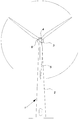
도 1 은 현대적인 풍력 터빈(1)을 도시하고,1 shows a
도 2 는 본 발명의 일 실시예에 따른 피동 위치 신호(passive position signal; PPS)의 무선 송수신(wireless transmission)을 위한 시스템을 도시하고,2 illustrates a system for wireless transmission of a passive position signal (PPS) in accordance with an embodiment of the present invention;
도 3 은 본 발명의 일 실시예에 따른 피동 위치 신호(PPS)의 무선 송수신을 위한 시스템을 도시하고,3 illustrates a system for wireless transmission and reception of a driven position signal (PPS) according to an embodiment of the present invention,
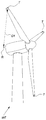
도 4a 및 도 4b 는 본 발명의 대안적 실시예에 따른 풍력 터빈 블레이드의 위치를 판정하기 위한 시스템을 도시한다.4A and 4B show a system for determining the position of a wind turbine blade according to an alternative embodiment of the present invention.
도 1 에는 현대적인 풍력 터빈(1)이 도시되어 있다. 풍력 터빈(1)은 기반부(foundation) 상에 위치된 타워(tower; 2)를 포함한다. 요오 메카니즘(yaw mechanism)을 구비한 풍력 터빈 너셀(wind turbine nacelle; 3)은 타워(2)의 상측에 위치된다.1 shows a
저속 샤프트(low speed shaft)는 너셀 전방의 밖으로 연장되고 또한 풍력 터빈 허브(wind turbine hub; 4)를 통해 풍력 터빈 로터(wind turbine rotor)와 연결된다. 풍력 터빈 로터는 적어도 하나의 로터 블레이드, 예를 들어 도시된 바와 같이 세 개의 로터 블레이드(rotor blade; 5)들을 포함한다.The low speed shaft extends out of the front of the nussel and is also connected to the wind turbine rotor via a wind turbine hub 4. The wind turbine rotor comprises at least one rotor blade, for example three
도 2 에는 본 발명의 일 실시예에 따라 소위 피동 위치 신호(PPS)의 무선 송수신을 위한 시스템이 도시되어 있다.2 shows a system for wireless transmission and reception of so-called driven position signals (PPS) in accordance with an embodiment of the present invention.
피동 위치 신호(PPS)라는 용어는, 기하학적 공간에서 풍력 터빈 블레이드의 위치를 반영하는 신호와 본 출원에 걸쳐 언급되는 다른 신호들 간의 혼동을 방지하기 위하여 도입된 것이다. 즉, 피동 위치 신호(PPS)는 하기의 상세한 설명에 걸쳐서 풍력 터빈 블레이드에 부착된 송신기 장치(transmitter arrangement; TA)로부터 송신된 신호를 의미한다.The term driven position signal (PPS) is introduced to avoid confusion between a signal reflecting the position of the wind turbine blade in geometric space and the other signals mentioned throughout this application. That is, the driven position signal PPS means a signal transmitted from a transmitter arrangement TA attached to a wind turbine blade over the following detailed description.
도면에는 위치 계산 컴퓨터(position calculation computer; PCC)와 연관된 수신 장치(receiving arrangement; RA) 및 풍력 터빈 블레이드(wind turbine blade; WTB)가 도시되어 있다. 하나 또는 수 개의 송신기(T)들은, 풍력 터빈 블레이드(WTB)와의 관계에서 미리 결정된 위치에 위치된 송신기 장치(transmitter arrangement; TA) 내에 배치된다. 송신기(T)들은 무선 신호를 송신하기 위한 수단을 포함한다. 무선으로 송신될 신호는 다양한 형태의 것일 수 있는바, 예를 들면 라디오 통신 신호(radio communication signal), 초음파 신호, 광 신호 등과 같은 것이 있다. 소위 피동 위치 신호(PPS)의 의미는, 그 신호가 위치의 계산을 위한 기반으로서 역할을 할 수 있는 데이터(예를 들어 타임 스탬프(time stamp), 위성 정보 등일 수 있는 데이터)를 포함하지 않는다는 것이다.The drawing shows a receiving arrangement (RA) and a wind turbine blade (WTB) associated with a position calculation computer (PCC). One or several transmitters T are arranged in a transmitter arrangement TA located at a predetermined position in relation to the wind turbine blade WTB. The transmitters T comprise means for transmitting a radio signal. The signal to be transmitted wirelessly may be of various forms, for example, a radio communication signal, an ultrasonic signal, an optical signal, or the like. The so-called passive position signal (PPS) means that the signal does not contain data that can serve as the basis for the calculation of the position (eg data that can be time stamps, satellite information, etc.). .
일 실시예에서, 피동 위치 신호(PPS)에 포함된 정보는 피동 위치 신호(PPS)를 송신하는 송신기의 식별 정보이다.In one embodiment, the information included in the driven position signal PPS is identification information of a transmitter transmitting the driven position signal PPS.
피동 위치 신호(PPS)는 수신 장치에 의하여 수신되고 위치 계산 컴퓨터(PCC) 에 의하여 통상적으로 수행되는 계산에 의하여 위치를 표시하게 되는바, 즉 위치는 송신기 장치(TA)로부터 보내지는 하나 또는 통상적으로는 수 개의 신호들에 기초하여 판정된다. 다시 말하면, 피동 위치 신호(PPS)는 본 발명의 실시예에 따라서 상대적으로 확고한 기본적인 방식(robust primitive way)으로 수립되는데, 주된 신호 처리는 외부적으로 수행될 수 있다.The driven position signal PPS is represented by a calculation received by the receiving device and usually performed by a position calculating computer PC, ie the position is one or typically sent from the transmitter device TA. Is determined based on several signals. In other words, the driven position signal PPS is established in a relatively robust primitive way according to an embodiment of the present invention, where the main signal processing can be performed externally.
수신 장치(RA)는 통상적으로, 송신기 장치(TA)에 의하여 보내지는 신호들을 수신하기 위한 하나 또는 수개의 수신기(R)들을 포함할 수 있다. 수신기(R)들은 본 발명의 실시예들에 따라서, 본 발명의 범위 내에 있는 복수의 위치들에 위치될 수 있는데, 예를 들면 타워(T)에 대한 관계에서 지면, 풍력발전 단지에 있는 다른 풍력 터빈들 등에 위치될 수 있다.The receiving device RA may typically comprise one or several receivers R for receiving the signals sent by the transmitter device TA. The receivers R may be located at a plurality of locations within the scope of the invention, in accordance with embodiments of the invention, for example in the ground relative to the tower T, other wind power in the wind farm. Turbines and the like.
송신기 장치(TA)에 관련된 송신기(S)는 전술된 예들에 따라 신호를 송신하기 위한 수단을 포함하는 임의의 기기(device) 또는 간단한 회로일 수 있다.The transmitter S associated with the transmitter device TA may be any device or simple circuit comprising means for transmitting a signal according to the examples described above.
송신기의 간단함 때문에, 이들의 전력 소비는 매우 낮을 수 있는데, 이것은 풍력 터빈 블레이드(WTB)에 관련된 분산된 송신기들이 태양 에너지 등과 같은 국부적으로 발생되는 에너지에 의하여 공급될 수 있음을 의미한다. 대안적으로는, 그 에너지가 배터리로부터 올 수도 있는데, 예를 들어 긴 수명의 배터리 전지 또는 다른 에너지 저장 기기와 같은 것이 있다.Because of the simplicity of the transmitters, their power consumption can be very low, which means that distributed transmitters associated with wind turbine blades (WTB) can be supplied by locally generated energy, such as solar energy. Alternatively, the energy may come from a battery, such as a long life battery cell or other energy storage device.
전술된 능동식 송신기들에 대한 다른 대안예로서는 에너지가 외부적으로 공급되는 피동식 송신기들이 있다. 본 발명의 일 실시예에 따라서 적용될 수 있는 일 형태의 피동식 송신기는 트랜스폰더(transponder) 또는 외부적으로 에너지가 공 급될 수 있는 임의의 종류의 송신기이다.Other alternatives to the active transmitters described above include passive transmitters that are externally supplied with energy. One type of passive transmitter that can be applied in accordance with one embodiment of the present invention is a transponder or any kind of transmitter that can be energized externally.
송신기(T)로부터 송신되는 이 신호는 매우 단순하고 짧은 발산(very simple and short burst), 예를 들어 라디오 주파수일 수 있다.This signal transmitted from the transmitter T may be very simple and short burst, for example a radio frequency.
위치 계산 컴퓨터(PCC)는, 셋 이상의 수신기(R)들과 송신기(T) 간의 거리를 측정함에 의하여, 풍력 터빈 블레이드(WTB)에 관련하여 배치된 송신기(T)의 위치를 계산할 수 있다. 본 발명의 실시예에 따르면, 그 신호의 송신과 수신 사이의 시간 지연을 측정함으로써 개별 수신기(R)들과 송신기(T) 간의 거리를 계산할 수 있는데, 이것은 신호가 공지된 속도로 이동하기 때문이다.The position calculation computer PCC may calculate the position of the transmitter T disposed relative to the wind turbine blade WTB by measuring the distance between three or more receivers R and the transmitter T. According to an embodiment of the invention, the distance between the individual receivers R and the transmitter T can be calculated by measuring the time delay between transmission and reception of the signal since the signal travels at a known speed. .
본 발명의 현저한 장점은 위치 계산 컴퓨터(PCC)가 풍력 터빈 블레이드(WTB)의 외부에 위치될 수 있다는 것이다. 이것은 위치 계산 컴퓨터(PCC)에 대해 예를 들어 소프트웨어와 업데이트와 같은 유지보수가 쉽게 이루어질 수 있음을 의미한다.A significant advantage of the present invention is that the position calculation computer (PCC) can be located outside of the wind turbine blade (WTB). This means that maintenance, such as software and updates, can be easily done for the position calculation computer (PCC).
위치 계산 컴퓨터(PCC)는 풍력 터빈 콘트롤러(WTC)에 소프트웨어적으로 또는 하드웨어적으로 구현된 일체적 부분일 수 있는데, 풍력 터빈 콘트롤러(WTC)는 통상적으로 풍력 터빈(WT)에 배치된다. 이것은, 치명적인 지연을 유발할 수 있는 데이터의 재전송(re-direction)이 필요없다는 점에서 유리할 수 있다. 대안적으로는, 위치 계산 컴퓨터(PCC)가 독립적으로 홀로 놓여진 기기일 수 있는데, 이것은, 지속적으로 또는 특별한 일이 발생하는 경우에 또는 요청에 따라서, 적당한 수신자에게 메시지를 보낼 수 있다.The position calculation computer PCC may be an integral part implemented in software or hardware in the wind turbine controller WTC, which is typically arranged in the wind turbine WT. This may be advantageous in that there is no need for re-direction of data which can cause fatal delays. Alternatively, the position computing computer (PCC) may be a device that is independently placed alone, which may send a message to the appropriate recipient, either continuously or in the event of special occurrence or upon request.
풍력 터빈 블레이드(WTB) 또는 블레이드 부분의 절대 위치 또는 상대 위치는 많은 다양한 방식들에 의하여 정해질 수 있다. 본 발명의 범위 내에 있는 많은 적용가능한 실시예들 중 일부가 아래에서 설명된다.The absolute or relative position of the wind turbine blade (WTB) or blade portion can be determined in many different ways. Some of the many applicable embodiments that fall within the scope of the invention are described below.
적어도 세 개의 수신기들에 대한 거리 및 그 수신기들의 위치를 판정함에 의하여, 위치 계산 컴퓨터(PCC)는 송신기의 위치를 계산할 수 있고, 따라서 풍력 터빈 블레이드(WTB)은 예를 들어 다변법(multilateration), 삼변법(trilateration) 또는 삼각법(triangulation) 프로세스(process)을 이용하게 된다. 이것을 기초로 하여, 풍력 터빈은, 풍력 터빈 블레이드(WTB)의 위치가 위험하다면 예를 들어 풍력 터빈을 정지시킴에 의하여 반응할 수 있다.By determining the distance to the at least three receivers and the position of the receivers, the position calculating computer PCC can calculate the position of the transmitter, so that the wind turbine blade WTB is for example multilateration, Trilateration or triangulation processes are used. Based on this, the wind turbine can react, for example, by stopping the wind turbine if the position of the wind turbine blade WTB is dangerous.
삼변법은, 삼각법과 유사한 방식으로 삼각형들의 기하형태를 이용하여 대상물들의 상대 위치를 판정하는 방법으로 이해된다. 물체의 위치를 계산하기 위하여 (적어도 하나의 알려진 거리와 함께) 각도 측정치들을 이용하는 삼각법과는 달리, 삼변법은 둘 이상의 기준 지점들의 알려진 위치들과 물체와 각 기준 지점 간의 측정된 거리를 이용한다. 그 거리는, RSSI (Received Signal Strength Indicator) 및 ToA (Time-of- Arrival)를 포함하는 기술들 중 다양한 기술을 활용함으로써 다양하게 측정될 수 있다. RSSI 는 수신기에서의 신호 파워(signal power)를 측정하는 기술로서 이해된다. 여기에서는 전송에 의한 파워 손실이 거리로 해석될 수 있다. ToA는 전파 시간(propagation time)을 기록하는 기술로서 이해되고, 신호 속도를 앎에 의하여 전파 시간이 거리로 해석될 수 있다. 삼변법만을 이용하여 2차원의 평면에 있는 지점의 상대 위치를 정확하고 고유하게 판정하기 위하여는, 일반적으로 적어도 3 개의 기준 지점들이 필요하다. 본 발명의 일 실시예에 따르면 이 기준 지점들은 수신기(R)들 또는 대안적으로는 송신기(T)로 이해된다. 삼변법 프로세스는 3차원의 위치를 계산하기 위하여 4 개의 동일 평면상의 기준들(수신기(R)들)을 필요로 한다.Trilaterality is understood as a method of determining the relative position of objects using the geometry of the triangles in a similar way to trigonometry. Unlike trigonometry, which uses angular measurements (with at least one known distance) to calculate the position of the object, trilateral method uses the known locations of two or more reference points and the measured distance between the object and each reference point. The distance can be measured variously by utilizing various ones of techniques including Received Signal Strength Indicator (RSSI) and Time-of-Arrival (ToA). RSSI is understood as a technique for measuring signal power at a receiver. Here, power loss due to transmission can be interpreted as distance. ToA is understood as a technique for recording propagation time, and the propagation time can be interpreted as a distance by subtracting the signal speed. In order to accurately and uniquely determine the relative position of a point in a two-dimensional plane using only the trilateral method, at least three reference points are generally required. According to one embodiment of the invention these reference points are understood as receivers R or alternatively transmitters T. The trilateral process requires four coplanar references (receivers R) to calculate the three-dimensional position.
본 발명의 다른 일 실시예에 따르면, 풍력 터빈 블레이드의 위치는 다변법 프로세스에 기초하여 계산된다.According to another embodiment of the present invention, the position of the wind turbine blade is calculated based on the multivariate process.
본 발명의 실시예에 따르면 쌍곡선 위치선정법(hyperbolic positioning)으로도 알려진 다변법은, 송신기(T)로부터 세 개 이상의 수신기(R)들로 송출되는 신호의 TDoA (time difference of arrival)를 정확히 계산함에 의하여, 송신기(T)의 위치를 판정하는 프로세스로 이해된다. 그것은 세 개 이상의 동기화된 송신기(T)들로부터 송신되는 신호의 도착에 관한 시간 차이를 측정함에 의하여 수신기(R)의 위치를 판정하는 경우에도 해당한다. 플랫폼으로부터 펄스가 송출되면, 그것은 공간적으로 떨어진 두 개의 수신기(R) 구역들에서 약간 다른 시간에 도착할 것인데, 그 도착의 시간 차이는 플랫폼으로부터의 각 수신기(R)의 상이한 거리에 기인한 것이다. 실제에 있어서, 두 개의 수신기(R)들의 주어진 위치들에 관하여는, 일련의 송출기(emitter) 위치들 전체가 동일한 도착 시간 차이의 측정치를 제공할 것이다. 두 개의 수신기 위치들 및 알려진 도착 시간 차이가 주어진다면, 송신기(T)의 가능한 위치들의 궤적은 쌍곡면일 것이다. 다시 말하면, 알려진 위치들에 두 개의 수신기(R)들이 있는 경우에 있어서는, 송출기가 쌍곡면 상에 있는 것으로 위치판정될 수 있다. 수신기(R)들은 펄스가 송신된 절대 시간을 알 필요가 없고 시간 차이만이 필요하다는 점에 유의해야 한다. 이제 세 번재 위치에 있는 세 번째의 수신 기(R)를 고려하면, 이것은 도착의 두 번째 시간 차이 측정치를 제공할 것이고, 따라서 두 번째 쌍공면 상에 송신기(T)가 있는 것으로 위치판정할 것이다. 이 두 개의 쌍곡면들의 교차선은 송출기가 놓여 있는 곡선을 나타낸다. 이제 네 번째 수신기(R)가 도입되면, 세 번재 도착 시간 차이의 측정치를 얻을 수 있고, 그로부터 귀결되는 세 번째 쌍곡면과 다른 세 개의 수신기(R)들에 의하여 이미 얻어진 상기 곡선의 교차점에 의하면 공간 상에 유일한 지점이 한정된다. 그러므로 송신기(T)의 위치는 3차원에서 완전히 판정된다.According to an embodiment of the present invention, a multivariate method, also known as hyperbolic positioning, accurately calculates the time difference of arrival (TDoA) of a signal transmitted from a transmitter (T) to three or more receivers (R). Is understood as a process of determining the position of the transmitter T. This is true even when determining the position of the receiver R by measuring a time difference relating to the arrival of a signal transmitted from three or more synchronized transmitters T. If a pulse is sent from the platform, it will arrive at slightly different times in the two receiver R zones that are spaced apart, the time difference of arrival being due to the different distance of each receiver R from the platform. In practice, with respect to the given positions of the two receivers R, the entire series of emitter positions will provide the same measure of arrival time difference. Given two receiver positions and a known arrival time difference, the trajectory of the possible positions of the transmitter T would be hyperbolic. In other words, in the case where there are two receivers R at known positions, the transmitter can be positioned as being on a hyperbolic surface. It should be noted that the receivers R do not need to know the absolute time at which the pulse was transmitted, only the time difference. Considering the third receiver R now in the third position, this will provide a second time difference measure of arrival, thus positioning the transmitter T on the second dipole. The intersection of these two hyperboloids represents the curve on which the transmitter lies. Now when the fourth receiver R is introduced, a measurement of the third time difference of arrival can be obtained, and according to the intersection of the curve already obtained by the third hyperbolic surface and the other three receivers R resulting therefrom, Only points in the phase are defined. Therefore, the position of the transmitter T is completely determined in three dimensions.
본 발명의 다른 일 실시예에 따르면, 풍력 터빈 블레이드의 위치는 삼각법 프로세스에 기초하여 계산된다. 삼각법은, 어떤 지점과 두 개의 다른 알려진 기준 좌표들에 의하여 형성되는 삼각형의 측면들과 각도들의 측정치가 주어진 때에, 사이너스(sinus) 의 법칙을 이용하여 삼각형의 일 측면의 길이를 계산함으로써 그 어떤 지점까지의 거리와 좌표를 알아내는 프로세스로 이해된다. 각도들은, 아테나 어레이(antenna array)에 입사하는 라디오 주파수 파동의 전파 방향을 판정하기 위한 기술인 AoA(Angle of Arrival) 기술을 이용함으로써 판정될 수 있다. 그 기술에 의하면, 안테나 어레이의 개별 요소들에서 TDoA (Time difference of Arrival)를 측정함에 의하여 그 방향이 계산되는데, 그 지연(delay)들로부터 AoA가 계산될 수 있다. 일반적으로 이 TDoA 측정은, 안테나 어레이에 있는 각 요소에서 수신되는 상(phase)의 차이를 측정함에 의하여 이루어진다.According to another embodiment of the invention, the position of the wind turbine blade is calculated based on the trigonometric process. Trigonometry is a method by calculating the length of one side of a triangle using the law of sinus, given a measure of the sides and angles of the triangle formed by a point and two other known reference coordinates. It is understood as the process of finding the distance and coordinates to a point. The angles can be determined by using the Angle of Arrival (AoA) technique, which is a technique for determining the propagation direction of radio frequency waves incident on an antenna array. According to the technique, the direction is calculated by measuring the time difference of Arrival (TDoA) at the individual elements of the antenna array, from which the AoA can be calculated. Typically this TDoA measurement is made by measuring the difference in phase received at each element in the antenna array.
본 발명의 실시예에 따르면, 풍력 터빈 블레이드의 위치는 다변법, 삼변법, 또는 삼각법 프로세스들 중의 임의의 것에 기초하여 계산된다. 또한 블레이드의 상대적 위치를 계산하기 위하여 다른 기본적인 계산 또는 미리 결정함(predetermination) 방법들을 이용하는 것도 가능한데, 예를 들어 수평의 X-Y 평면인 공간 상의 일 평면 상에 블레이드의 위치를 기하학적으로 투사시키는 것(geometric projecting)이 있다.According to an embodiment of the present invention, the position of the wind turbine blade is calculated based on any of the multilateral, trilateral, or trigonometric processes. It is also possible to use other basic calculation or predetermination methods to calculate the relative position of the blade, for example geometrically projecting the blade's position on one plane in space, which is a horizontal XY plane. projecting).
본 발명에 따른 다수의 송신기(T)들 및 수신기(R)들의 설치 중에는, 장비의 캘리브레이션 프로세스(calibration process)를 수행하는 것이 바람직하다. 이것은 계산 컴퓨터(PCC)와 관련하여 측정된 데이터와의 비교를 위해 몇몇의 기준 신호들을 설정함에 의하여 이루어질 수 있다. 이와 같은 방식에 의하여, 어떤 경우들에 있어서 풍력 터빈 블레이드(WTB)가 위험한 상태에 있는지의 여부에 관한 계산이 최적화되어서, 블레이드가 타워와 충돌하는 것과 같은 치명적인 오류가 방지되도록 최적화될 수 있다.During the installation of multiple transmitters T and receivers R according to the invention, it is desirable to carry out a calibration process of the equipment. This can be done by setting some reference signals for comparison with the measured data in relation to the computational computer (PCC). In this manner, in some cases the calculation as to whether or not the wind turbine blades (WTB) are in a dangerous state can be optimized, so that fatal errors such as the blades colliding with the tower can be optimized.
본 발명의 실시예에 따르면, 송신기(T)들 및 수신기(R)들은 피동 또는 능동식의 RFID 태그(radio frequency identification tag)들에 의하여 구현된다. RFID 태그는 라디오 신호들을 통하여 데이터를 송신할 수 있는 식별 라벨 또는 태그(identification label or tag)로 이해된다. RFID 태그는 전기적 트랜스폰더로서 이해되는데, 이것은 라벨이 부착된 물건을 식별하기 위하여 이용될 수 있는 정보를 저장하는 라벨 상의 바코드와 유사한 방식으로, 예를 들어 트랜스폰더가 부착되는 물건을 식별하기 위하여 이용될 수 있는 정보를 저장한다. RFID 태그는, 예를 들어 RFID 송신기 또는 송수신기와 같은 송신기로부터 라디오 주파수 쿼리(radio- frequency queries)를 수신하고 그에 응답하는 것을 가능하게 하는 안테 나를 포함할 수 있다. 피동적인 RFID 태그는 어떠한 영구적 에너지 공급도 없는 태그로서 이해된다. 이것은 외부의 공급원으로부터 전자기파의 형태로 에너지를 받는다. 따라서, 피동적인 RFID 태그는 안테나에 의하여 생성되는 자기장 안에 놓인 때에 활성화되는 트랜스폰더로서 이해된다. 코일 내에서 유도된 전류는 그 태크 안에 배치된 커패시터(capacitor)를 충전시킨다. 피동식 RFID 태그와는 달리, 능동식 RFID 태그는 자체적인 내부 전력 공급원을 구비하는데, 이것은 밖으로 나가는 신호를 발생시키는 임의의 집적회로에 전력을 공급하는데에 이용된다.According to an embodiment of the invention, the transmitters T and the receivers R are implemented by passive or active radio frequency identification tags. RFID tags are understood as identification labels or tags that can transmit data via radio signals. RFID tags are understood as electrical transponders, which are used in a manner similar to barcodes on labels that store information that can be used to identify a labeled object, for example to identify the object to which the transponder is attached. Store information that can be The RFID tag may include an antenna that enables receiving and responding to radio-frequency queries, for example, from a transmitter such as an RFID transmitter or transceiver. Passive RFID tags are understood as tags without any permanent energy supply. It receives energy in the form of electromagnetic waves from external sources. Thus, passive RFID tags are understood as transponders that are activated when placed in a magnetic field generated by an antenna. Current induced in the coil charges a capacitor placed in the tag. Unlike a passive RFID tag, an active RFID tag has its own internal power source, which is used to power any integrated circuit that generates an outgoing signal.
나아가, RFID 는 RFID 태그 또는 트랜스폰더로 불리는 기기를 이용하여 데이터를 저장하고 데이터를 원격으로 추출함에 의존하는, 자동식 식별 방법으로서 이해된다.Furthermore, RFID is understood as an automatic identification method, relying on storing data and extracting the data remotely using a device called an RFID tag or transponder.
RFID 태그는, 예를 들어 전자기파를 이용하여 식별하기 위한 목적을 위한 제품에 적용될 수 있는 물체이다.RFID tags are objects that can be applied to products for the purpose of identifying, for example, using electromagnetic waves.
RFID 태그는 적어도 두 부분을 포함할 수 있다. 첫 번째 부분은, 예를 들어 정보를 저장 및 처리하고, (라디오 주파수) 신호를 변조 및 복조하거나, 또는 다른 특화된 기능을 갖는 집적회로이다. 두 번째 부분은, 그 신호를 수신 및 송신하기 위한 안테나 구조물이다.The RFID tag may include at least two parts. The first part is an integrated circuit, for example, which stores and processes information, modulates and demodulates (radio frequency) signals, or has other specialized functions. The second part is an antenna structure for receiving and transmitting the signal.
칩리스 RFID(chipless RFID)는 집적회로 없이 태그들의 개별적 식별을 가능하게 하는데, 이로써 태그들이 통상의 태그들보다 낮은 비용으로 제품에 직접 인쇄될 수 있다.Chipless RFID enables the individual identification of tags without integrated circuits, which allows tags to be printed directly onto the product at lower cost than conventional tags.
본 출원에 있어서 트랜스폰더는 무선 통신, 모니터링, 또는 제어 기기로서 이해되는데, 이 기기는 들어오는 신호를 취하여 그에 대해 자동적으로 응답한다. 트랜스폰더라는 용어는 송신기(transmitter)와 응답기(responder)의 단축어이며, 능동식이거나 또는 피동식인 것일 수 있다.In the present application, a transponder is understood as a wireless communication, monitoring, or control device, which takes an incoming signal and automatically responds to it. The term transponder is an abbreviation for transmitter and responder and may be active or passive.
피동식 트랜스폰더는, 예를 들어 컴퓨터가 어떤 물체를 식별하는 것을 가능하게 한다. 피동식 트랜스폰더는 트랜스폰더가 가지고 있는 데이터를 디코딩(decoding)하고 전사(transcription)하는 능동식 센서와 함께 이용될 수 있다.A passive transponder, for example, allows a computer to identify an object. A passive transponder can be used with an active sensor that decodes and transcribes the data possessed by the transponder.
식별 시스템에서는 단순한 능동식 트랜스폰더가 이용될 수 있다. 일 예는 모니터링 또는 제어 지점으로부터의 요청을 수신하는 때에 부호화된 신호(coded signal)를 송신하는 RFID 기기이다. 트랜스폰더 출력 신호는 추적되어서, 트랜스폰더의 위치가 지속적으로 모니터링될 수 있다. 입력부(수신기)의 주파수 및 출력부(송신기)의 주파수는 미리 할당된다.In an identification system, a simple active transponder can be used. One example is an RFID device that transmits a coded signal when receiving a request from a monitoring or control point. The transponder output signal is tracked so that the position of the transponder can be continuously monitored. The frequency of the input unit (receiver) and the frequency of the output unit (transmitter) are assigned in advance.
RFID 태그가 본 발명에 다른 송신기로서 적용되는 때에는, 그것이 태그의 식별정보로, 그리고 위치 계산 컴퓨터에 의해 위치의 계산을 더 잘 하기 위하여 활용될 수 있는 초광역 펄스 시퀀스(UWB (Ultra Wide Band) pulse sequence)와 함께 RF교신(radio frequency message)을 할 수 있다.When an RFID tag is applied as another transmitter in the present invention, it can be utilized as identification information of the tag and by the position calculation computer to better calculate the position (UWB (Ultra Wide Band) pulse). A radio frequency message can be communicated with the sequence.
피동 위치 신호는, 그 자체로서는 위치를 표시하는 데이터를 포함하지 않지만 수신된 신호가 처리되는 때에는 위치를 표시하게 되는 데이터 신호로서 이해되는데, 그 처리는 통상적으로 위치 계산 컴퓨터(PCC)에 의하여 이루어진다. 여기에서 송신기 장치(TA)의 위치는 송신기 장치(TA)로부터 보내지는 신호에 기초하여 수신기에서 판정된다.The driven position signal, by itself, does not include data indicating the position, but is understood as a data signal which indicates the position when the received signal is processed, which processing is usually done by a position calculation computer (PCC). Here, the position of the transmitter device TA is determined at the receiver based on the signal sent from the transmitter device TA.
위치를 표시하는 데이터는 상대 위치 또는, 공간에서 유일한 지점인 절대 위치일 수 있다.The data indicative of the position may be a relative position or an absolute position which is the only point in space.
본 발명의 실시예에 따르면 풍력 터빈 블레이드가 간단한 송신기만을 포함한다는 것은 매우 유리한 특징이다. 이것은 복잡한 회로, 안테나 등이 풍력 터빈 블레이드에 구현되지 않아도 된다는 것을 의미하는데, 이것은 신호를 수신하기 위한 수단 및 위치를 표시하는 데이터를 송신 및 재송신하기 위한 수단 둘 다를 구비하여야 하는 종래 기술의 시스템과는 상이한 것이다.According to an embodiment of the invention it is a very advantageous feature that the wind turbine blade comprises only a simple transmitter. This means that complex circuits, antennas, etc. do not have to be implemented in the wind turbine blades, which is different from prior art systems, which must have both means for receiving signals and means for transmitting and retransmitting data indicative of location. It is different.
도 3 에는 본 발명의 실시예에 따른 피동 위치 신호(PPS)의 무선 송수신용 시스템이 도시되어 있다. 이 도면에는 피동 위치 신호(PPS)를 수신 장치(RA)로 송신하는 송신기 장치(TA)를 포함하는 풍력 터빈 블레이드(WTB)가 도시되어 있는데, 이 예에 따르면 그 수신 장치(RA)는 세 개의 상이한 수신기들(Rl , R2, ... Rn)을 포함한다. 수신기(R)들은 임의의 장소에 배치될 수 있으나, 세 개의 상이한 위치들에 배치되어야 한다. 수신기들은 위치 계산 컴퓨터(PCC)와 연관될 수 있는데, 그 위치 계산 컴퓨터는 송신기(T)의 위치를 계산할 수 있고, 이에 따라 풍력 터빈 블레이드(WTB)의 위치를 계산할 수 있는 것이다. 본 발명의 실시예에서는 네 개의 수신기들이 활용될 수도 있는데 이 경우에는 풍력 터빈 블레이드(WTB)의 위치를 계산하기 위하여 전술된 바와 같이 삼변법 프로세스가 이용될 수 있다. 본 발명의 다른 실시예에 따르면, 임의의 갯수의 수신기(R)들이 활용될 수 있다. 수신기(R)들 간의 거리들(D, ...,Dm)은, 위에서 설명된 바와 같이, 풍력 터빈 블레이드의 절대 위치 또는 상대 위치를 판정하기 위하여, 풍력 터빈 블레이드에 대해 미리 결정 된 관계로 위치된 송신기들의 계산을 위하여 이용될 수 있다.3 shows a system for wireless transmission and reception of a driven position signal (PPS) in accordance with an embodiment of the present invention. In this figure there is shown a wind turbine blade WTB comprising a transmitter device TA for transmitting the driven position signal PPS to a receiving device RA. Different receivers R1, R2, ... Rn. The receivers R can be located in any place, but must be located in three different locations. The receivers can be associated with a position calculation computer (PCC), which can calculate the position of the transmitter (T) and thus calculate the position of the wind turbine blade (WTB). In an embodiment of the invention four receivers may be utilized, in which case a trilateration process may be used as described above to calculate the position of the wind turbine blade (WTB). According to another embodiment of the invention, any number of receivers R may be utilized. The distances D, ..., Dm between the receivers R are located in a predetermined relationship relative to the wind turbine blade, in order to determine the absolute or relative position of the wind turbine blade, as described above. Can be used for the calculation of the transmitters.
도 4a 및 도 4b 에는 본 발명의 대안적 실시예에 따른 풍력 터빈 블레이드의 위치를 판정하기 위한 시스템이 도시되어 있다. 이 실시예에서는 수신기(R)가 풍력 터빈(WT)의 너셀에서 로터의 순환적 회전 영역의 근원부에 위치된다. 하나 또는 수개의 신호 송신기(T)들은 풍력 터빈 블레이드(WTB)에 관계되어 위치되는바, 바람직하게는 로터의 중앙부로부터 먼 풍력 터빈 블레이드(WTB)의 단부에 위치된다. 이와 같은 방식으로, 송신기로부터 수신기로 피동 위치 신호(PPS)를 송신함에 의하여 송신기(T)와 수신기(R) 간의 정확한 거리를 판정하는 것이 가능하게 되는데, 그 신호가 수신기들에 의하여 수신되는 때에는, 신호의 이동 속도가 알려진 경우라면, 거리(D1, D2)로서 해석될 수 있다. 미리 결정된 기준 파라미터들과 측정된 거리를 비교함에 의하여, 풍력 터빈 블레이드(WTB)가 예를 들어 타워와 충돌할 수 있을 정도로 너무 많이 휘었는지의 여부를 판정할 수 있다. 그러므로 신호는 수신기(R)로부터 풍력 터빈 제어부로 송신될 수 있다. 도 4b 에는 휜 풍력 터빈 블레이드(WTB)들을 구비한 풍력 터빈의 예가 도시되어 있는데, 이 경우에는 송신기(T)와 수신기(R) 간의 거리(D2)가 도 4a 에 도시된 거리(D1)보다 작다. 이와 같은 방식으로, 풍력 터빈 블레이드(WTB)의 휨을 판정하는 것이 가능하게 된다.4A and 4B show a system for determining the position of a wind turbine blade according to an alternative embodiment of the present invention. In this embodiment, the receiver R is located at the root of the circular rotational region of the rotor in the nussel of the wind turbine WT. One or several signal transmitters T are located relative to the wind turbine blades WTB, preferably at the ends of the wind turbine blades WTB, which are remote from the center of the rotor. In this way, it is possible to determine the exact distance between the transmitter T and the receiver R by transmitting the driven position signal PPS from the transmitter to the receiver, when the signal is received by the receivers, If the moving speed of the signal is known, it can be interpreted as the distances D1 and D2. By comparing the measured distance with the predetermined reference parameters, it can be determined whether the wind turbine blades WTB are bent too much, for example to collide with the tower. Therefore, the signal can be transmitted from the receiver R to the wind turbine controller. 4b shows an example of a wind turbine with wind turbine blades WTB, in which case the distance D2 between the transmitter T and the receiver R is smaller than the distance D1 shown in FIG. 4A. . In this manner, it becomes possible to determine the curvature of the wind turbine blade WTB.
Claims (20)
Applications Claiming Priority (2)
| Application Number | Priority Date | Filing Date | Title |
|---|---|---|---|
| DKPA200700499 | 2007-03-30 | ||
| DKPA200700499 | 2007-03-30 |
Publications (1)
| Publication Number | Publication Date |
|---|---|
| KR20100015853A true KR20100015853A (en) | 2010-02-12 |
Family
ID=39808738
Family Applications (1)
| Application Number | Title | Priority Date | Filing Date |
|---|---|---|---|
| KR1020097022214A KR20100015853A (en) | 2007-03-30 | 2008-03-31 | Wind turbine blade position determination system |
Country Status (6)
| Country | Link |
|---|---|
| US (1) | US20100021298A1 (en) |
| EP (1) | EP2129909A2 (en) |
| JP (1) | JP2010522848A (en) |
| KR (1) | KR20100015853A (en) |
| CN (1) | CN101675245A (en) |
| WO (1) | WO2008119354A2 (en) |
Cited By (2)
| Publication number | Priority date | Publication date | Assignee | Title |
|---|---|---|---|---|
| KR20150019778A (en) * | 2013-08-16 | 2015-02-25 | 현대중공업 주식회사 | Apparatus and method for motion detection in wind power generator |
| KR101690171B1 (en) * | 2015-07-22 | 2016-12-27 | 가부시끼가이샤 히다치 세이사꾸쇼 | Wind power generator and wireless communication method therein |
Families Citing this family (38)
| Publication number | Priority date | Publication date | Assignee | Title |
|---|---|---|---|---|
| US20080101930A1 (en) * | 2002-09-23 | 2008-05-01 | Bosche John V | Wind turbine blade deflection control system |
| ES2665771T3 (en) * | 2008-07-11 | 2018-04-27 | Vestas Wind Systems A/S | System to monitor a restoration factor of a population of wind turbines |
| WO2010017820A2 (en) * | 2008-08-13 | 2010-02-18 | Vestas Wind Systems A/S | Wind turbine rotor and method of calibrating rotor blade pitch |
| US20100097220A1 (en) * | 2008-10-17 | 2010-04-22 | Ge Wind Energy Gmbh | Wireless information system for wind turbine components |
| US20100143128A1 (en) * | 2008-12-23 | 2010-06-10 | General Electric Company | Wind turbine yaw bearing determination |
| DE102009007623A1 (en) * | 2009-02-05 | 2010-08-19 | Repower Systems Ag | Parameterization of wind turbines |
| WO2010123461A1 (en) * | 2009-04-21 | 2010-10-28 | Vestas Wind Systems A/S | A wind turbine comprising a rotor |
| EP2284985B1 (en) * | 2009-08-10 | 2012-06-06 | Silicon Valley Micro M Corporation | Brushless DC motor with RFID rotor magnet position sensing |
| TWI474581B (en) * | 2009-08-10 | 2015-02-21 | Silicon Valley Micro M Corp | Brushless d.c. motor, brushless d.c. motor system, and method of initially calibrating a brushless d.c. motor after assembly |
| CN101997378B (en) * | 2009-08-28 | 2015-06-03 | 硅谷微M股份有限公司 | Brushless direct current motor having function of sensing position of RFID rotor magnet |
| DE102009058595A1 (en) * | 2009-12-17 | 2011-06-22 | Siemens Aktiengesellschaft, 80333 | Detection of deformation of a wing of a wind turbine |
| GB2479923A (en) * | 2010-04-29 | 2011-11-02 | Vestas Wind Sys As | A method and system for detecting angular deflection in a wind turbine blade, or component, or between wind turbine components |
| DE102010019014A1 (en) * | 2010-05-03 | 2011-11-03 | Siemens Aktiengesellschaft | Measurement of the deflection of a rotor blade of a wind turbine |
| US8131402B2 (en) * | 2010-06-30 | 2012-03-06 | General Electric Company | System for detecting proximity between a wind turbine blade and a tower wall |
| KR101697070B1 (en) * | 2010-09-23 | 2017-01-17 | 인스티튜트 퓌어 룬트퐁크테크닉 게엠베하 | Wind turbine with electromagnetic wave transmission system |
| EP2436922A1 (en) * | 2010-10-04 | 2012-04-04 | Siemens Aktiengesellschaft | Arrangement to supply a sensor in a wind turbine blade with electrical power |
| US8267655B2 (en) * | 2010-12-20 | 2012-09-18 | General Electric Company | Method for controlling a wind turbine, and wind turbine arrangement |
| EP2485011B1 (en) * | 2011-02-07 | 2013-08-28 | Siemens Aktiengesellschaft | Arrangement to measure the deflection of an object |
| US9249781B2 (en) * | 2011-12-30 | 2016-02-02 | Robert Bosch Gmbh | Method for robust wireless wind turbine condition monitoring |
| US9383436B2 (en) * | 2012-01-18 | 2016-07-05 | Tdc Acquisition Holdings, Inc. | One way time of flight distance measurement |
| AT512155B1 (en) * | 2012-06-05 | 2013-06-15 | Hainzl Industriesysteme Gmbh | Device for detecting an ice covering on the rotor blades of a wind turbine |
| PL2885531T3 (en) * | 2012-08-17 | 2017-09-29 | Lm Wp Patent Holding A/S | A blade deflection monitoring system |
| GB201222540D0 (en) * | 2012-12-14 | 2013-01-30 | Lm Wp Patent Holding As | A system and method for wind turbine sensor calibration |
| EP2778602B1 (en) | 2013-03-14 | 2015-10-14 | Siemens Aktiengesellschaft | Arrangement to measure the deflection of a blade of a wind turbine |
| ES2691025T3 (en) * | 2013-05-23 | 2018-11-23 | Vestas Wind Systems A/S | Improvements related to wind turbines |
| DK3041736T3 (en) * | 2013-09-06 | 2019-05-27 | Lm Wind Power Int Tech Ii Aps | One-way Flight time Distance Measurement |
| US9765757B2 (en) | 2013-11-22 | 2017-09-19 | General Electric Company | System and method for preventing rotor blade tower strike |
| ES2773677T3 (en) | 2014-12-17 | 2020-07-14 | Vestas Wind Sys As | Wind turbine related improvements |
| JP6567909B2 (en) * | 2015-07-22 | 2019-08-28 | 株式会社日立製作所 | Wind power generator and wireless communication method in wind power generator |
| CN105069495B (en) * | 2015-08-12 | 2018-02-16 | 洛阳双瑞风电叶片有限公司 | It is a kind of to be used for wind electricity blade production status and the method for O&M condition monitoring |
| US20180335015A1 (en) | 2015-11-11 | 2018-11-22 | Lm Wp Patent Holding A/S | A Deflection Monitoring System for a Wind Turbine Blade |
| CN105626389B (en) * | 2015-12-28 | 2018-04-20 | 北京金风科创风电设备有限公司 | System and method for monitoring tower state of wind generating set |
| MA45744A (en) | 2016-02-23 | 2019-01-02 | Lm Wind Power Int Tech Ii Aps | BLADE SAGGING MONITORING SYSTEM |
| EP3626965A1 (en) * | 2018-09-21 | 2020-03-25 | Siemens Gamesa Renewable Energy A/S | Object position and/or speed and/or size and/or direction detection device for a wind turbine |
| EP3719306A1 (en) * | 2019-04-01 | 2020-10-07 | Siemens Gamesa Renewable Energy A/S | Wind turbine with tower deflection detection |
| CN111963385B (en) * | 2020-08-17 | 2021-06-29 | 上海电气风电集团股份有限公司 | Wind generating set blade clearance monitoring device and method and wind generating set |
| US11939949B2 (en) * | 2020-09-09 | 2024-03-26 | Vestas Wind Systems A/S | Wind turbine blade |
| CN112283048B (en) * | 2020-10-28 | 2022-03-08 | 西安热工研究院有限公司 | Wind turbine generator blade clearance detection method and device |
Family Cites Families (9)
| Publication number | Priority date | Publication date | Assignee | Title |
|---|---|---|---|---|
| JP2627986B2 (en) * | 1991-07-26 | 1997-07-09 | 進 佐久間 | Security method through sending and receiving emergency signals |
| US6396438B1 (en) * | 1999-09-24 | 2002-05-28 | Slc Technologies | System and method for locating radio frequency identification tags using three-phase antenna |
| DE10032314C1 (en) * | 2000-07-04 | 2001-12-13 | Aloys Wobben | Rotor blade angle evaluation method for wind-powered energy plant uses processor supplied with data for measured distance between rotor blade and mast of energy plant |
| JP2003194908A (en) * | 2001-12-28 | 2003-07-09 | Icom Inc | Synchronizing system and apparatus for measuring location of mobile body using the same |
| CA2426711C (en) * | 2002-05-02 | 2009-11-17 | General Electric Company | Wind power plant, control arrangement for a wind power plant, and method for operating a wind power plant |
| US7246991B2 (en) * | 2002-09-23 | 2007-07-24 | John Vanden Bosche | Wind turbine blade deflection control system |
| DK177602B1 (en) * | 2004-01-16 | 2013-11-18 | Lm Wind Power As | Monitoring the operation of a wind power plant |
| DE102004060449A1 (en) * | 2004-12-14 | 2006-06-29 | Aloys Wobben | Rotor blade for wind power station has rotor blade nose, deposition sensor device arranged in area of rotor blade nose with transmitter for wireless transmission of signals via transmission link and receiver for receiving signals |
| JP2006338601A (en) * | 2005-06-06 | 2006-12-14 | Hitachi Plant Technologies Ltd | Work management support system |
-
2008
- 2008-03-31 WO PCT/DK2008/000125 patent/WO2008119354A2/en active Application Filing
- 2008-03-31 JP JP2010501371A patent/JP2010522848A/en active Pending
- 2008-03-31 CN CN200880010673A patent/CN101675245A/en active Pending
- 2008-03-31 EP EP08715602A patent/EP2129909A2/en not_active Withdrawn
- 2008-03-31 KR KR1020097022214A patent/KR20100015853A/en not_active Application Discontinuation
-
2009
- 2009-09-30 US US12/570,930 patent/US20100021298A1/en not_active Abandoned
Cited By (2)
| Publication number | Priority date | Publication date | Assignee | Title |
|---|---|---|---|---|
| KR20150019778A (en) * | 2013-08-16 | 2015-02-25 | 현대중공업 주식회사 | Apparatus and method for motion detection in wind power generator |
| KR101690171B1 (en) * | 2015-07-22 | 2016-12-27 | 가부시끼가이샤 히다치 세이사꾸쇼 | Wind power generator and wireless communication method therein |
Also Published As
| Publication number | Publication date |
|---|---|
| WO2008119354A3 (en) | 2009-07-30 |
| WO2008119354A8 (en) | 2009-10-22 |
| EP2129909A2 (en) | 2009-12-09 |
| US20100021298A1 (en) | 2010-01-28 |
| CN101675245A (en) | 2010-03-17 |
| JP2010522848A (en) | 2010-07-08 |
| WO2008119354A2 (en) | 2008-10-09 |
Similar Documents
| Publication | Publication Date | Title |
|---|---|---|
| KR20100015853A (en) | Wind turbine blade position determination system | |
| Sanpechuda et al. | A review of RFID localization: Applications and techniques | |
| WO2008113104A1 (en) | Coarse and fine location for tagged items | |
| EP2341361B1 (en) | Method and system for locating a hand-held terminal | |
| US10001545B2 (en) | System and method for improved location accuracy | |
| US7864040B2 (en) | Localization system and localization method and mobile position data transmitter | |
| JP4871836B2 (en) | Position detection system and position detection method | |
| US11582621B2 (en) | Sensor-assisted technique for RF power normalization in locationing applications | |
| US20080315999A1 (en) | Wireless communication system for tracking assets with affixed electronic smart tags and methods thereof | |
| CN106802412B (en) | Short-distance mobile positioning system and method based on laser and wireless technology | |
| JP2010522848A5 (en) | ||
| Almaaitah et al. | 3D passive tag localization schemes for indoor RFID applications | |
| US20180080795A1 (en) | Vehicle positioning with rfid tags | |
| US9128187B2 (en) | Detection of a position of an object | |
| CN109407079B (en) | Area positioning method based on attitude sensor calibration | |
| KR101012244B1 (en) | Method and apparatus for real time location tracking using rfid | |
| CN102573055A (en) | Method for locating nodes in wireless sensor network | |
| CN210075591U (en) | Ultra-wideband indoor positioning system based on dynamic reference label | |
| CN110824422A (en) | High-precision indoor positioning device positioning method | |
| JP2007010629A (en) | Secondary surveillance radar response signal receiver and secondary surveillance radar response signal receiving method | |
| CN102395897A (en) | Area identification and area definition by utilizing rf technology | |
| CN113242981A (en) | Polarization axis attenuation and cross-polarization resistant antenna orientation assembly for tracked objects | |
| CN114980308A (en) | Positioning method, positioning device and computer storage medium | |
| CN106249201A (en) | A kind of ultrasonic locating active electronic label group device and localization method | |
| JP2009075032A (en) | Location detection system |
Legal Events
| Date | Code | Title | Description |
|---|---|---|---|
| WITN | Application deemed withdrawn, e.g. because no request for examination was filed or no examination fee was paid |