KR20090082446A - Method and apparatus for providing active compliance in a probe card assembly - Google Patents

Method and apparatus for providing active compliance in a probe card assembly Download PDF

Info

Publication number
KR20090082446A
KR20090082446A KR1020097011126A KR20097011126A KR20090082446A KR 20090082446 A KR20090082446 A KR 20090082446A KR 1020097011126 A KR1020097011126 A KR 1020097011126A KR 20097011126 A KR20097011126 A KR 20097011126A KR 20090082446 A KR20090082446 A KR 20090082446A
Authority
KR
South Korea
Prior art keywords
probes
probe card
compliance
probe
card assembly
Prior art date
Application number
KR1020097011126A
Other languages
Korean (ko)
Inventor
케이쓰 제이 브레인링거
Original Assignee
폼팩터, 인코포레이티드
Priority date (The priority date is an assumption and is not a legal conclusion. Google has not performed a legal analysis and makes no representation as to the accuracy of the date listed.)
Filing date
Publication date
Application filed by 폼팩터, 인코포레이티드 filed Critical 폼팩터, 인코포레이티드
Publication of KR20090082446A publication Critical patent/KR20090082446A/en

Links

Images

Classifications

    • GPHYSICS
    • G01MEASURING; TESTING
    • G01RMEASURING ELECTRIC VARIABLES; MEASURING MAGNETIC VARIABLES
    • G01R1/00Details of instruments or arrangements of the types included in groups G01R5/00 - G01R13/00 and G01R31/00
    • G01R1/02General constructional details
    • G01R1/06Measuring leads; Measuring probes
    • GPHYSICS
    • G01MEASURING; TESTING
    • G01RMEASURING ELECTRIC VARIABLES; MEASURING MAGNETIC VARIABLES
    • G01R31/00Arrangements for testing electric properties; Arrangements for locating electric faults; Arrangements for electrical testing characterised by what is being tested not provided for elsewhere
    • G01R31/28Testing of electronic circuits, e.g. by signal tracer
    • G01R31/2851Testing of integrated circuits [IC]
    • G01R31/2886Features relating to contacting the IC under test, e.g. probe heads; chucks
    • G01R31/2891Features relating to contacting the IC under test, e.g. probe heads; chucks related to sensing or controlling of force, position, temperature
    • GPHYSICS
    • G01MEASURING; TESTING
    • G01RMEASURING ELECTRIC VARIABLES; MEASURING MAGNETIC VARIABLES
    • G01R31/00Arrangements for testing electric properties; Arrangements for locating electric faults; Arrangements for electrical testing characterised by what is being tested not provided for elsewhere
    • G01R31/26Testing of individual semiconductor devices
    • HELECTRICITY
    • H01ELECTRIC ELEMENTS
    • H01LSEMICONDUCTOR DEVICES NOT COVERED BY CLASS H10
    • H01L22/00Testing or measuring during manufacture or treatment; Reliability measurements, i.e. testing of parts without further processing to modify the parts as such; Structural arrangements therefor

Abstract

A probe card assembly can comprise a first source of compliance and a second source of compliance. The probe card assembly can further comprise a controller, which can be configured to apportion a total compliance demand placed on the probe card assembly between the first source of compliance and the second source of compliance.

Description

프로브 카드 어셈블리에서 능동 컴플라이언스를 제공하기 위한 방법 및 장치{METHOD AND APPARATUS FOR PROVIDING ACTIVE COMPLIANCE IN A PROBE CARD ASSEMBLY}METHOD AND APPARATUS FOR PROVIDING ACTIVE COMPLIANCE IN A PROBE CARD ASSEMBLY}

본 발명은, 프로브 카드 어셈블리에서 능동 컴플라이언스를 제공하기 위한 방법 및 장치에 관한 것이다.The present invention relates to a method and apparatus for providing active compliance in a probe card assembly.

도 1a는, 전자 장치(106)와의 임시적인 압력 기반의 전기 접속을 확립하기 위해 사용될 수 있는 접촉기 장치(102)를 예시한다. 단자(108)들과 프로브(104)들간의 임시적인 전기 접속은 프로브(104)들에 맞대어 단자(108)들을 누르고, 및/또는, 단자(108)들에 맞대어 프로브(104)들을 누름으로써 확립될 수 있다. 전형적으로, 프로브(104)는 유연하고(즉, 가요성이어서 외력의 인가시 움직이거나 변위할 수 있음), 그에 따라 단자(108)와 프로브(104)를 함께 누름으로써 발생할 수 있는 힘을 흡수할 수 있다.1A illustrates a contactor device 102 that may be used to establish a temporary pressure based electrical connection with the electronic device 106. The temporary electrical connection between the terminals 108 and the probes 104 is established by pressing the terminals 108 against the probes 104 and / or by pressing the probes 104 against the terminals 108. Can be. Typically, the probe 104 is flexible (ie flexible and can move or displace upon application of an external force), thus absorbing the force that may occur by pressing the terminal 108 and the probe 104 together. Can be.

여러가지 이유때문에 이와 같은 컴플라이언스에 대한 필요성이 발생할 수 있다.There may be a need for such compliance for a variety of reasons.

이러한 이유들 중 하나는 과이동(over travel)이며, 그 예가 도 1b 및 1c에 예시되어 있다. 도 1b에 도시된 바와 같이, 전자 장치(106)의 입력 및/또는 출력 단자(108)들은 접촉기 장치(102)의 전기 도전성 프로브(104)들과 접촉하게 된다. 위치(110)는 단자(108)들과 프로브(104)들간의 제1 접촉선을 식별한다. 도 1c에 도시된 바와 같이, 전자 장치(106)는 대개, 단자(108)와 프로브(104)들 사이의 제1 접촉선(110)을 넘어서 전형적으로 "과이동"이라 불리는 거리(112)만큼 이동한다. 무엇보다도 과이동은 프로브(104)들과 단자(108)에서의 불균일성(예를 들어, 단자(108)들의 높이에서의 약간의 차이, 단자(108)와 프로브(104)들 사이의 비평탄성)을 보상하고, 프로브(104)들과 단자(108)들 사이의 전기 접속이, 테스트 신호가 프로브(104)들을 통해 전자 장치(106)의 단자(108)들로 신뢰성있게 입력되기에 충분히 도전성이 될 것을 보장한다.One of these reasons is over travel, an example of which is illustrated in FIGS. 1B and 1C. As shown in FIG. 1B, the input and / or output terminals 108 of the electronic device 106 are in contact with the electrically conductive probes 104 of the contactor device 102. Location 110 identifies the first contact line between terminals 108 and probes 104. As shown in FIG. 1C, the electronic device 106 typically extends beyond the first contact line 110 between the terminal 108 and the probes 104 by a distance 112, typically referred to as “overtravel”. Move. Above all, overtravel is a nonuniformity in the probes 104 and the terminal 108 (eg, a slight difference in the height of the terminals 108, non-flatness between the terminal 108 and the probes 104). The electrical connection between the probes 104 and the terminals 108 is sufficiently conductive so that the test signal is reliably input through the probes 104 to the terminals 108 of the electronic device 106. To be guaranteed.

물리학의 법칙에 따라, 연관된 힘을 포함한 과이동은 흡수되거나 보상되어야 한다. 언급한 바와 같이, 전형적으로, 유연할 수 있는 접촉기 장치(102)의 프로브(104)들은, 과이동의 전부는 아니더라도 대부분을 흡수할 수 있다. 도 1c에서, 프로브(104)들은, 과이동(112)의 전부는 아니라도 대부분을 흡수한 채 압축되어 있는 것으로 도시되어 있다. 일부 환경하에서, 프로브(104)들의 과도한 압축은 프로브(104)들 및/또는 전자 장치(106)를 손상시킬 수 있다.According to the laws of physics, overtravel, including associated forces, must be absorbed or compensated for. As mentioned, typically the probes 104 of the contactor device 102, which may be flexible, may absorb most, if not all, of the overtravel. In FIG. 1C, the probes 104 are shown compressed while absorbing most, if not all, of the overtravel 112. Under some circumstances, excessive compression of the probes 104 can damage the probes 104 and / or the electronic device 106.

컴플라이언스에 대한 필요성을 야기하는 또 다른 원인은, 단자(108)들이 프로브(104)들에 맞대어 눌러져 있는 동안 접촉기 장치(102)의 열적으로 유도된 이동이다. 예를 들어, 접촉기 장치(102)를 가로질러 발현될 수 있는 열적 경사도는, 접촉기 장치(102)가 뒤틀리거나, 굽거나, 또는 기타 방식으로 움직이도록 유발하고, 이것은, 프로브(104)들과 단자(108)들 사이의 힘의 레벨에 영향을 미칠 수 있다.Another cause of the need for compliance is thermally induced movement of the contactor device 102 while the terminals 108 are pressed against the probes 104. For example, thermal gradients that may develop across the contactor device 102 cause the contactor device 102 to warp, bend, or otherwise move, which causes the probes 104 and terminals to move. May affect the level of force between the 108.

도 1a-1c는, 테스트될 전자 장치와 전기 접속을 이루기 위한 프로브들을 갖는 접촉기 장치를 도시한다.1A-1C show a contactor device having probes for making an electrical connection with an electronic device to be tested.

도 2는 본 발명의 일부 실시예들에 따른 예시적 테스트 시스템을 도시한다.2 illustrates an exemplary test system in accordance with some embodiments of the present invention.

도 3은 본 발명의 일부 실시예들에 따른 예시적 액츄에이터를 도시한다.3 illustrates an exemplary actuator in accordance with some embodiments of the present invention.

도 4는 본 발명의 일부 실시예들에 따른 또 다른 예시적 액츄에이터를 도시한다.4 illustrates another exemplary actuator in accordance with some embodiments of the present invention.

도 5는 본 발명의 일부 실시예들에 따른 도 2에 도시된 예시적 프로브 카드 어셈블리의 프로브 헤드 어셈블리를 도시한다.5 illustrates a probe head assembly of the exemplary probe card assembly shown in FIG. 2 in accordance with some embodiments of the present invention.

도 6은 액츄에이터 및 프로브들에 의해 도 2에 도시된 프로브 카드 어셈블리에 주어지는 컴플라이언스 기여분을 나타내는 가상 스프링을 도시한다.FIG. 6 illustrates a virtual spring representing the compliance contributions given to the probe card assembly shown in FIG. 2 by actuators and probes.

도 7은 본 발명의 일부 실시예들에 따른 도 2에 도시된 제어기의 예시적 구성을 도시한다.7 illustrates an exemplary configuration of the controller shown in FIG. 2 in accordance with some embodiments of the present invention.

도 8은 본 발명의 일부 실시예들에 따른 도 7의 제어기에 의해 실행될 수 있는 예시적 프로세스를 도시한다.8 illustrates an example process that may be executed by the controller of FIG. 7 in accordance with some embodiments of the present invention.

도 9a-11b는, 본 발명의 일부 실시예들에 따른 도 8의 프로세스의 예시적 구현을 도시한다.9A-11B illustrate an example implementation of the process of FIG. 8 in accordance with some embodiments of the present invention.

도 12a 및 12b는 본 발명의 일부 실시예들에 따른 도 8의 프로세스의 또 다 른 예시적 구현을 도시한다.12A and 12B show another example implementation of the process of FIG. 8 in accordance with some embodiments of the present invention.

도 13a-14b는 본 발명의 일부 실시예들에 따른 도 8의 프로세스의 추가적 예시적 구현을 도시한다.13A-14B show additional exemplary implementations of the process of FIG. 8 in accordance with some embodiments of the present invention.

도 15a 및 15b는 본 발명의 일부 실시예들에 따른 프로브 헤드 어셈블리의 예시적 구성을 도시한다.15A and 15B show an exemplary configuration of a probe head assembly in accordance with some embodiments of the present invention.

도 16a-18c는 본 발명의 일부 실시예들에 따른 도 8의 프로세스의 추가의 예시적 구현을 도시한다.16A-18C illustrate further example implementations of the process of FIG. 8 in accordance with some embodiments of the present invention.

본 명세서는 본 발명의 예시적인 실시예와 응용을 기술한다. 그러나, 본 발명은 이들 실시예와 응용만으로 제한되는 것은 아니며, 실시예들 및 응용들이 동작하거나 본 명세서에서 기술된 방식만으로 제한되는 것은 아니다. 게다가, 도면들은 간략도 또는 부분도를 도시할 수도 있고, 도면들 내의 요소들의 크기는 과장되거나, 명료성을 위해 비율대로 도시되지 않을 수도 있다. 또한, 용어 "~상에"가 본 명세서에서 사용될 때, 한 물체(예를 들어, 재료, 층, 기판 등)가 직접 다른 물체 상에 있거나 한 물체와 다른 물체 사이에 하나 이상의 중간 물체가 있는지에 관계없이, 한 물체가 직접 또다른 물체 "상에" 있을 수 있다. 또한, 방향(예를 들어, 위, 아래, 상부, 하부, 측부, "x", "y", "z" 등)은, 만일 제공된다면, 상대적인 것으로서, 설명과 논의를 용이하게 하기 위해 단지 예로서 제공되는 것이지, 제한을 의미하는 것은 아니다.This specification describes exemplary embodiments and applications of the present invention. However, the present invention is not limited to these embodiments and applications only, and the embodiments and applications are not limited to the manner in which they operate or are described herein. In addition, the drawings may show a simplified or partial view, and the size of elements in the drawings may be exaggerated or not drawn to scale for clarity. In addition, when the term “on” is used herein, it is determined whether one object (eg, material, layer, substrate, etc.) is directly on another object or there is one or more intermediate objects between one object and another. Regardless, one object may be directly "on" another. Also, directions (eg, up, down, top, bottom, side, “x”, “y”, “z”, etc.) are relative, if provided, as examples, and are merely examples to facilitate explanation and discussion. It is provided as, but does not imply a limitation.

도 2는 본 발명의 일부 실시예들에 따라 하나 이상의 전자 장치(230)를 테스 팅하기 위한 예시적 테스트 시스템(200)의 간략화된 블럭도를 예시한다. 이하에서는, 테스트될 하나 이상의 전자 장치(230)들은 "테스트 대상 장치" 또는 "DUT"라 언급될 것이다. 게다가, "테스트 대상 장치" 또는 "DUT"(230)는 단품화되지 않은 반도체 웨이퍼의 하나 이상의 다이들, (팩키징되었던 팩키징되지 않았던) 웨이퍼로부터 단품화된 하나 이상의 반도체 다이들, 캐리어 또는 기타 홀딩 장치에 배치된 단품화된 반도체 다이들의 어레이의 하나 이상의 다이들, 하나 이상의 멀티다이 전자 모듈, 하나 이상의 인쇄 회로 기판, 또는 기타 임의 타입의 전자 장치 또는 장치들일 수 있다. 게다가, DUT란, 하나 이상의 이와 같은 장치들을 말할 수 있다.2 illustrates a simplified block diagram of an example test system 200 for testing one or more electronic devices 230 in accordance with some embodiments of the present invention. In the following, one or more electronic devices 230 to be tested will be referred to as a "test device" or "DUT". In addition, “device under test” or “DUT” 230 may include one or more dies of an un singulated semiconductor wafer, one or more semiconductor dies, carrier or other holding device singulated from a wafer (which was packaged and not packaged). One or more dies, one or more multi-die electronic modules, one or more printed circuit boards, or any other type of electronic device or devices disposed in an array of singulated semiconductor dies disposed therein. In addition, a DUT may refer to one or more such devices.

도시된 바와 같이, 테스트 시스템(200)은, 프로그램된 범용 컴퓨터, 특별 목적 컴퓨터, 및/또는 기타의 전자 회로 또는 전자 장치일 수 있는 테스터(202)를 포함할 수 있다. 테스터(202)는 DUT(230)에 입력될 테스트 신호를 발생하도록 구성될 수 있으며, 테스터(202)는 또한 테스트 신호에 응답하여 DUT(230)에 의해 발생된 응답 신호를 수신하여 분석하도록 구성될 수 있다.As shown, test system 200 may include tester 202, which may be a programmed general purpose computer, special purpose computer, and / or other electronic circuitry or electronic device. The tester 202 may be configured to generate a test signal to be input to the DUT 230, and the tester 202 may also be configured to receive and analyze a response signal generated by the DUT 230 in response to the test signal. Can be.

도 2에 역시 도시된 바와 같이, 테스트 시스템(200)은, DUT(230)를 홀딩하고 이동시키기 위한 가동 홀더(232)를 구비한 하우징(212)을 포함할 수 있다. 하우징(212)은, 예를 들어, 반도체 다이들을 테스팅하는데 흔하게 사용되는 프로브일 수 있고, 홀더(232)는 척(chuck) 또는 스테이지(stage)일 수 있다. 홀더(232)는 DUT(230)를 받치도록 구성될 수 있고, DUT(230)를 이동시키도록 구성될 수도 있다. 예를 들어, 홀더(232)는 DUT(230)를 "x", "y", 및 "z" 방향으로 이동시키도록 구성될 수 있다. 또한, 홀더(232)는 추가로 "x"축 및 "y"축에 대해 DUT(230)를 기울이 고, "z" 축에 관해 DUT(230)를 회전시키도록 구성될 수 있다(도 2에서 "y" 축은 지면 안팎으로 연장되고 있다). "y" 축은 설명의 편의를 위해 약간 비스듬하게 도시되어 있다.As also shown in FIG. 2, the test system 200 may include a housing 212 having a movable holder 232 for holding and moving the DUT 230. The housing 212 may be, for example, a probe commonly used to test semiconductor dies, and the holder 232 may be a chuck or stage. Holder 232 may be configured to support DUT 230 and may be configured to move DUT 230. For example, the holder 232 may be configured to move the DUT 230 in the "x", "y", and "z" directions. In addition, the holder 232 may be further configured to tilt the DUT 230 about the "x" axis and the "y" axis and to rotate the DUT 230 about the "z" axis (FIG. 2). The "y" axis extends in and out of the ground). The axis "y" is shown slightly oblique for convenience of explanation.

도 2에 역시 도시된 바와 같이, 테스트 시스템(200)은, DUT(230)의 입력 및/또는 출력 단자(228)들과 접촉하여 전기 접속을 이루도록 배치된 전기 도전성 프로브(226)들을 포함하는 프로브 카드 어셈블리(234)를 포함할 수 있다. 도시된 바와 같이, 프로브 카드 어셈블리(234)는 하우징(212)의 장착판(210)에 부착될 수 있고, 홀더(232)는 단자(228)들과 프로브(226)들이 정렬하도록 "x, y" 축을 따라 DUT(230)를 이동시킬 수 있고, 그 다음, 단자(228)들을 프로브(226)들과 접촉시키기 위해 'z" 축을 따라 DUT(230)를 이동시킬 수 있다.As also shown in FIG. 2, the test system 200 includes probes that include electrically conductive probes 226 disposed to make electrical connections with the input and / or output terminals 228 of the DUT 230. It may include a card assembly 234. As shown, the probe card assembly 234 can be attached to the mounting plate 210 of the housing 212, and the holder 232 is “x, y” to align the terminals 228 with the probes 226. Move the DUT 230 along the axis, and then move the DUT 230 along the 'z' axis to bring the terminals 228 into contact with the probes 226.

도 2에 도시된 바와 같이, 프로브 카드 어셈블리(234)는 장착 구조물(236), 배선 기판(208), 가요성 전기 커넥터(218), 및 프로브(226)를 포함하는 프로브 헤드 어셈블리(222)를 포함할 수 있다. 프로브(226)는 복원성이 있는 도전성 구조물이다. 적절한 프로브(226)의 비제한적 예로서는, 미국 특허번호 제5,476,211호와 미국 특허번호 제5,917,707호 및 미국 특허번호 제6,336,269호에 기술된 탄성 물질로 코팅된 프로브 헤드 어셈블리(222) 상의 도전성 단자(미도시)에 접합된 코어 와이어로 형성된 복합 구조물이 포함될 수 있다. 프로브(226)는, 대안으로서, 미국특허 번호 제5,994,152호, 미국 특허번호 제6,033,935호, 미국 특허번호 6,255,126호, 미국 특허번호 제6,945,827호, 미국 특허출원 공개 번호 제2001/0044225호, 미국 특허출원 공개 번호 2004/0016119호에 기술된 스프링 요소와 같은 리소그래픽적 으로 형성된 구조물일 수 있다. 프로브(226)의 역시 다른 비제한적 예가, 미국 특허번호 제6,827,584호, 미국 특허번호 제6,640,432호, 미국 특허번호 제6,441,315호, 및 미국 특허출원 공개 번호 제2001/0012739호(P130-US)에 공개되어 있다. 프로브(226)의 다른 비제한적인 예로서, 도전성 포고 핀(pogo pin), 범프, 스터드, 스탬프된 스프링, 니들, 버클링 빔 등이 포함된다.As shown in FIG. 2, the probe card assembly 234 includes a probe head assembly 222 that includes a mounting structure 236, a wiring board 208, a flexible electrical connector 218, and a probe 226. It may include. The probe 226 is a resilient conductive structure. Non-limiting examples of suitable probes 226 include conductive terminals (not shown) on the probe head assembly 222 coated with an elastic material described in US Pat. No. 5,476,211 and US Pat. No. 5,917,707 and US Pat. No. 6,336,269. It may include a composite structure formed of a core wire bonded to). The probe 226 may alternatively be described as US Patent No. 5,994,152, US Patent No. 6,033,935, US Patent No. 6,255,126, US Patent No. 6,945,827, US Patent Application Publication No. 2001/0044225, US Patent Application It may be a lithographically formed structure, such as the spring element described in publication number 2004/0016119. Still other non-limiting examples of probes 226 are disclosed in US Pat. No. 6,827,584, US Pat. No. 6,640,432, US Pat. No. 6,441,315, and US Patent Application Publication No. 2001/0012739 (P130-US). It is. Other non-limiting examples of probe 226 include conductive pogo pins, bumps, studs, stamped springs, needles, buckling beams, and the like.

배선 기판(208)은 테스터(202)로부터 통신 채널(204)로의 전기 인터페이스(미도시)를 포함할 수 있다. 통신 채널(204)들은, DUT(230)에 전력을 공급하기 위해 테스터로부터의 전력과 접지, 및 DUT(230)로의 입력을 위한 테스트 신호를 제공하고, 테스트 신호에 응답하여 DUT(230)에 의해 발생된 응답 신호를 테스터에 제공하기 위한 복수개의 개개 통신 경로를 제공할 수 있다. 통신 채널(204)들은, 프로브 카드 어셈블리(234)나, 하우징(212) 내 또는 하우징(212) 상의 다른 장치들(미도시)에 제어 신호를 제공하거나, 이들로부터의 상태 신호를 제공하기 위해 사용될 수 있다. 예를 들어, 통신 채널들은 홀더(232)의 이동을 제어하기 위해 사용될 수 있다. 통신 채널(204)들은, 무엇보다도, 동축 케이블, 광섬유, 무선 송신기/수신기, 스위치, 드라이브 및 수신기, 또는 이들 중 2개 이상의 조합을 포함할 수 있다. 채널(204)들과 배선 기판(208) 사이의 전기 인터페이스(미도시)는, 채널(204)들과 전기 접속을 이루기 위한 임의의 적절한 수단을 포함할 수 있다. 예를 들어, 전기 인터페이스(미도시)는 ZIF(zero-insertion-force) 전기 커넥터, 포고 핀 패드 등을 배선 기판(208) 상에 포함할 수 있다.The wiring board 208 may include an electrical interface (not shown) from the tester 202 to the communication channel 204. The communication channels 204 provide a test signal for power and ground from the tester and input to the DUT 230 to power the DUT 230, and by the DUT 230 in response to the test signal. A plurality of individual communication paths may be provided for providing the generated response signal to the tester. The communication channels 204 may be used to provide control signals to, or provide status signals from, the probe card assembly 234 or other devices (not shown) in or on the housing 212. Can be. For example, communication channels can be used to control the movement of the holder 232. The communication channels 204 may include, among other things, coaxial cable, fiber optics, wireless transmitter / receiver, switches, drives and receivers, or a combination of two or more thereof. The electrical interface (not shown) between the channels 204 and the wiring substrate 208 may include any suitable means for making electrical connections with the channels 204. For example, the electrical interface (not shown) may include a zero-insertion-force (ZIF) electrical connector, pogo pin pad, and the like on the wiring board 208.

배선 기판(208)은 채널(204)로부터 가요성 전기 커넥터(218)로의 복수의 전 기 경로(미도시)를 포함할 수 있다. 배선 기판(208)은 예를 들어 인쇄 회로 기판을 포함할 수 있고, 전기 경로는, 배선 기판(208) 상의 또는 배선 기판(208) 내의 전기 전도성의 트레이스(미도시), 및 배선 기판(208)을 관통하는 전기 도전성의 비아(미도시)를 포함할 수 있다.The wiring board 208 may include a plurality of electrical paths (not shown) from the channel 204 to the flexible electrical connector 218. The wiring board 208 may include, for example, a printed circuit board, and the electrical path may include an electrically conductive trace (not shown) on or in the wiring board 208, and the wiring board 208. It may include an electrically conductive via (not shown) penetrating the through.

가요성 전기 커넥터(218)는 배선 기판(208)으로부터 프로브 헤드 어셈블리(222)로의 가요성 전기 도전성 경로(미도시)를 제공할 수 있다. 가요성 전기 커넥터(218)는, 이후에 논의되는 바와 같이 프로브 헤드 어셈블리(222)가 액츄에이터(215)에 의해 이동되는 때조차, 배선 기판(208)과 프로브 헤드 어셈블리(222) 사이에서 전기 접속을 유지하기에 충분히 탄력적인(또는 유연한) 임의 타입의 전기 접속을 포함할 수 있다. 예를 들어, 전기 커넥터(218)는 가요성 와이어를 포함할 수 있다. 또 다른 예로서, 전기 커넥터(218)는 (예를 들어, 미국 특허번호 제5,974,622호의 도 5에 개시된 인터포우저(504)와 같은) 인터포우저를 포함할 수 있다.The flexible electrical connector 218 can provide a flexible electrically conductive path (not shown) from the wiring board 208 to the probe head assembly 222. The flexible electrical connector 218 provides an electrical connection between the wiring board 208 and the probe head assembly 222 even when the probe head assembly 222 is moved by the actuator 215 as will be discussed later. It may include any type of electrical connection that is flexible enough (or flexible) to maintain. For example, electrical connector 218 can include flexible wires. As another example, electrical connector 218 can include an interposer (such as interposer 504 disclosed in FIG. 5 of US Pat. No. 5,974,622, for example).

프로브 헤드 어셈블리(222)는, 프로브 헤드 어셈블리(222)를 통해 프로브(226)들까지의 전기 도전성 경로(미도시)를 포함할 수 있다. 따라서, 배선 기판(208), 가요성 전기 커넥터(218), 및 프로브 헤드 어셈블리(222)를 통한 도전성 경로(미도시)는, 채널(204)들과, 프로브(226)들 사이에서 개개의 전기 접속을 제공할 수 있다. 프로브(226)들은 다시 DUT 단자(228)들과 전기 접속을 이룬다.The probe head assembly 222 may include an electrically conductive path (not shown) through the probe head assembly 222 to the probes 226. Thus, a conductive path (not shown) through the wiring board 208, the flexible electrical connector 218, and the probe head assembly 222 separates the electrical power between the channels 204 and the probes 226. Can provide a connection. The probes 226 are again in electrical connection with the DUT terminals 228.

프로브 헤드 어셈블리(222)는 많은 상이한 형태 및 설계를 취할 수 있다. 예를 들어, 프로브 헤드 어셈블리(222)는 프로브(226)가 부착되어 있는 단일의 기판 을 포함할 수 있다. 대안으로서, 프로브 헤드 어셈블리(222)는 프로브(226)들이 부착된 복수의 프로브 기판(미도시)을 포함할 수 있고, 이들 프로브 기판들은 더 큰 기판(미도시)에 부착되거나 서로 부착될 수 있다. 복수 기판 프로브 헤드 어셈블리(222)의 예가, 2005년 6월 24일 출원된 미국특허출원 번호 제11/165,833호에 공개되어 있다.Probe head assembly 222 can take many different forms and designs. For example, the probe head assembly 222 may comprise a single substrate to which the probe 226 is attached. Alternatively, the probe head assembly 222 may comprise a plurality of probe substrates (not shown) to which the probes 226 are attached, which may be attached to a larger substrate (not shown) or to one another. . An example of a plurality of substrate probe head assembly 222 is disclosed in US patent application Ser. No. 11 / 165,833, filed June 24, 2005.

장착 구조물(236)은, 경성 구조물(예를 들어, 금속판 구조물)과, 장착판(210)에 착탈될 수 있는 메커니즘 또는 메커니즘들(미도시)을 포함할 수 있다. 이와 같은 부착 메커니즘들의 비제한적 예로서는, 볼트, 스크류, 클램프 등이 포함될 수 있다. 도 2에 도시된 구성에 대한 대안으로서, 장착 구조물(236)이 아닌 배선 기판(208)이 장착판(210)에 부착될 수 있다. 이와 같은 구성에서, 장착 구조물(236)이 보강 구조물로서 배선 기판(208)에 부착될 수 있다. 또는, 장착 구조물(236)이 프로브 카드 어셈블리(234)에 포함될 필요가 없다.The mounting structure 236 can include a rigid structure (eg, a metal plate structure) and a mechanism or mechanisms (not shown) that can be attached to and detached from the mounting plate 210. Non-limiting examples of such attachment mechanisms may include bolts, screws, clamps, and the like. As an alternative to the configuration shown in FIG. 2, the wiring board 208, rather than the mounting structure 236, may be attached to the mounting plate 210. In such a configuration, the mounting structure 236 may be attached to the wiring board 208 as a reinforcing structure. Or, the mounting structure 236 need not be included in the probe card assembly 234.

도 2에 도시된 바와 같이, 프로브 카드 어셈블리(234)는 또한 복수의 액츄에이터(215)를 포함할 수 있다. 복수의 액츄에이터들 각각은 예를 들어 엔진(214) 및 구동 메커니즘(220)을 포함할 수 있다. 구동 메커니즘(220)은 가동 요소(movable element)일 수 있고, 엔진(214)은 구동 메커니즘(220)을 이동시키도록 구성될 수 있다. 엔진(214)은 모터(예를 들어, 전기 모터)이거나, 구동 메커니즘(220)을 이동시킬 수 있는 기타 임의의 장치일 수 있다. (비록 3개의 액츄에이터(215)가 도 2에 도시되어 있지만, 더 많거나 더 적은 수의 액츄에이터가 사용될 수 있다). 각각의 엔진(214)은 프로브 헤드 어셈블리(222)를 향해 그 연관된 구동 메커니즘(220)을 선택적으로 구동하거나 프로브 헤드 어셈블리(222)로부터 멀어지도록 구동 메커니즘(220)을 끌어낼 수 있다. 따라서, 각각의 액츄에이터(215)는 프로브 카드 어셈블리의 일부를 장착 구조물(236)을 향해 또는 이로부터 멀어지도록 이동시키게끔 선택적으로 제어될 수 있다.As shown in FIG. 2, the probe card assembly 234 may also include a plurality of actuators 215. Each of the plurality of actuators may include, for example, an engine 214 and a drive mechanism 220. The drive mechanism 220 can be a movable element and the engine 214 can be configured to move the drive mechanism 220. Engine 214 may be a motor (eg, an electric motor) or any other device capable of moving drive mechanism 220. (Though three actuators 215 are shown in FIG. 2, more or fewer actuators may be used). Each engine 214 may selectively drive its associated drive mechanism 220 toward the probe head assembly 222 or pull the drive mechanism 220 away from the probe head assembly 222. Thus, each actuator 215 may be selectively controlled to move a portion of the probe card assembly toward or away from the mounting structure 236.

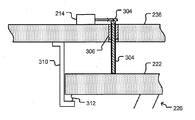
도 3은, 본 발명의 일부 실시예들에 따라 구동 메커니즘(220)이 볼트(304)를 포함할 수 있는 예시적 액츄에이터(215)를 도시하고 있다. 도 3에서, (금속판을 포함할 수 있는) 장착 구조물(236)이 프로브 헤드 어셈블리(222)에서와 같이 부분도로서 도시되어 있다. 설명의 편의를 위해, 가요성 전기 커넥터(218) 및 배선 기판(208)은 도 3에 도시되어 있지 않다. 브라켓(310)은 프로브 헤드 어셈블리(222)를 장착 구조물(236)에 부착할 수 있고, 스프링(312)(한개가 도시되어 있지만 더 많은 스프링이 제공될 수 있다)은 장착 구조물(236)을 향해 프로브 헤드 어셈블리(222)를 편향시킬 수 있다. 볼트(304)는 도시된 바와 같이 장착 구조물(236) 내의 나사 플러그(306)(예를 들어, 나사형 부시)에 끼울 수 있다. 나사 플러그(306)는 장착 구조물(236) 내의 구멍 내에 직접 형성된 나사부(threading)로 대체될 수 있다. 연관된 엔진(214)은 볼트(304)를 선택적으로 회전시킬 수 있다. 엔진(214)이 한 방향으로 볼트(304)를 회전시킬 때, 볼트(304)는 프로브 헤드 어셈블리(222)를 향해 이동하여 프로브 헤드 어셈블리(222)를 누를 수 있으며, 스프링(312)의 편향력에 맞서 장착판(236)으로부터 멀어지도록 프로브 헤드 어셈블리(222)를 이동시킬 수 있다. 대조적으로, 엔진(214)이 그 반대 방향으로 볼트(304)를 회전시킬 때, 볼트(304)는 프로브 헤드 어셈블리(222)로부터 멀어지는 방향으로 이동할 수 있으며, 이것은, 스프링(312)의 편향력이 장착판(236)을 향해 프로브 헤드 어셈블리(222)를 밀도록 허용한다.3 illustrates an example actuator 215 in which drive mechanism 220 may include bolt 304 in accordance with some embodiments of the present invention. In FIG. 3, mounting structure 236 (which may include a metal plate) is shown as a partial view as in probe head assembly 222. For convenience of description, the flexible electrical connector 218 and the wiring board 208 are not shown in FIG. 3. Bracket 310 may attach probe head assembly 222 to mounting structure 236, and spring 312 (one is shown but more springs may be provided) toward mounting structure 236. The probe head assembly 222 may be deflected. Bolt 304 may fit into threaded plug 306 (eg, threaded bush) in mounting structure 236 as shown. The screw plug 306 may be replaced with a threading formed directly in the hole in the mounting structure 236. Associated engine 214 may selectively rotate bolt 304. When the engine 214 rotates the bolt 304 in one direction, the bolt 304 can move toward the probe head assembly 222 and depress the probe head assembly 222 and the biasing force of the spring 312. The probe head assembly 222 can be moved away from the mounting plate 236. In contrast, when the engine 214 rotates the bolt 304 in the opposite direction, the bolt 304 can move in a direction away from the probe head assembly 222, which means that the biasing force of the spring 312 is Allow pushing the probe head assembly 222 toward the mounting plate 236.

도 4는, 본 발명의 일부 실시예들에 따른 차동 스크류 어셈블리(402) 형태의 예시적 액츄에이터(215)와 엔진(214)을 예시한다. 도 3에 도시된 바와 같이, 장착 구조물(236) 및 프로브 헤드 어셈블리(222)는 부분도로서 도시되어 있고, 가요성 전기 커넥터(218)와 프로브 헤드 어셈블리(208)는 도시되어 있지 않다. 도 4에 도시된 바와 같이, 차동 스크류 어셈블리(402)는 외측 스크류 요소(406) 내에 끼워지는 내측 스크류 요소(404)를 포함할 수 있다. 외측 스크류 요소(406)는 그 자체로 장착 구조물(236) 내의 나사 구멍(410)(또는 나사 플러그(예를 들어, 나사형 부시)) 내에 끼워질 수 있으며, 내측 스크류 요소의 끝부분은 프로브 헤드 어셈블리(222)에 부착된 스터드 요소(408) 내에 끼워질 수 있다. 대안으로서, 내측 스크류 요소(404)는 스터드 요소(408)에 체결, 납땜, 용접, 또는 기타의 방식으로 부착될 수 있다. 역시 또 다른 대안으로서, 내측 스크류 요소(404)와 스터드 요소(408)는 일체로 형성될 수 있다.4 illustrates an example actuator 215 and engine 214 in the form of a differential screw assembly 402 in accordance with some embodiments of the present invention. As shown in FIG. 3, the mounting structure 236 and the probe head assembly 222 are shown as a partial view, and the flexible electrical connector 218 and the probe head assembly 208 are not shown. As shown in FIG. 4, the differential screw assembly 402 can include an inner screw element 404 that fits within the outer screw element 406. The outer screw element 406 can itself fit into a screw hole 410 (or screw plug (eg, threaded bush)) in the mounting structure 236, with the end of the inner screw element being the probe head It may fit within stud element 408 attached to assembly 222. Alternatively, the inner screw element 404 may be fastened, soldered, welded, or otherwise attached to the stud element 408. As yet another alternative, the inner screw element 404 and the stud element 408 may be integrally formed.

연관된 엔진(214)은 외측 스크류 요소(406)를 선택적으로 회전시킬 수 있다. 외측 스크류 요소(406)가 한 방향으로 회전할 때, 프로브 헤드 어셈블리는 장착 구조물(236)로부터 멀어지도록 밀릴 수 있으며, 외측 스크류 요소(406)가 반대 방향으로 회전할 때, 프로브 헤드 어셈블리(222)는 장착 구조물(236) 쪽으로 향하도록 당겨질 수 있다.Associated engine 214 may selectively rotate outer screw element 406. When the outer screw element 406 rotates in one direction, the probe head assembly can be pushed away from the mounting structure 236, and when the outer screw element 406 rotates in the opposite direction, the probe head assembly 222 Can be pulled toward the mounting structure 236.

도 3 및 도 4에 도시된 예시적 액츄에이터(215)는 이용될 수 있는 많은 수의 가능한 액츄에이터들 중 단 2개의 예만을 도시하고 있다. 기타의 비제한적 예로서는, 기어박스(gearbox)를 구비한 미세 피치 스크류, 공기압 액츄에이터, 열 액츄에이터, 유압 액츄에이터, 압전 액츄에이터, 선형 모터, 보이스 코일 액츄에이터 솔레노이드, 자기변형 액츄에이터(예를 들어, 테르페놀-D(terfenol-D) 액츄에이터), 쐐기 시스템 구동 선형 모터 액츄에이터, 형상 기억 합금(예를 들어, Nitinol) 등이 포함된다.The example actuator 215 shown in FIGS. 3 and 4 only shows two examples of the large number of possible actuators that may be used. Other non-limiting examples include fine pitch screws with gearboxes, pneumatic actuators, thermal actuators, hydraulic actuators, piezo actuators, linear motors, voice coil actuator solenoids, magnetostrictive actuators (e.g. terphenol-D (terfenol-D) actuators), wedge system driven linear motor actuators, shape memory alloys (eg Nitinol) and the like.

(프로브 헤드 어셈블리(222)만을 도시하고 있는) 도 5를 참조하면, 액츄에이터(215)의 구성이나 유형에 관계없이, 복수의 액츄에이터(215)를 이용함으로써, 각각의 구동 메커니즘(220)에 의해 외력(502)이 프로브 헤드 어셈블리(222)의 상이한 지역들에 선택적으로 인가될 수 있다. 도 5에 역시 도시된 바와 같이, 외력(502)의 선택적 인가에 의해, 프로브 헤드 어셈블리(222)는, (도 2 참조) 장착 구조물(236)에 관하여 "z"축을 따라 이송되거나, 및/또는 "x"축 및/또는 "y"축에 관하여 회전할 수 있다. 만일 3개 보다 많은 액츄에이터(215)가 사용된다면, 프로브 헤드 어셈블리(222)는 구부러지거나 뒤틀릴 수 있고, 다른 동작들도 역시 가능하다.Referring to FIG. 5 (showing only the probe head assembly 222), regardless of the configuration or type of the actuator 215, by using the plurality of actuators 215, the external force is driven by each drive mechanism 220. 502 may optionally be applied to different regions of the probe head assembly 222. As also shown in FIG. 5, by selective application of the external force 502, the probe head assembly 222 is transported along the “z” axis with respect to the mounting structure 236 (see FIG. 2), and / or It may rotate about the "x" axis and / or the "y" axis. If more than three actuators 215 are used, the probe head assembly 222 may bend or warp, and other operations are also possible.

도 2의 테스트 시스템(200)을 이용하여 DUT(230)를 테스트하기 위해, 홀더(232)는 DUT(230)의 단자(228)들을 프로브 카드 어셈블리(234)의 프로브(226)들과 정렬시킬 수 있다. 홀더(232)는 대체로 "x" 축 및 "y"축을 따라 DUT(230)를 이동시킴으로써 정렬을 행할 수 있다. 그 다음, 홀더(232)는 대체로 "z" 축을 따라 프로브 카드 어셈블리(234)를 향하여 DUT(230)를 이동시킬 수 있다. 홀더(232)는, 과이동(112)의 예를 도시하는 도 1a-1c에 관해 전술된 논의와 모순없이, 통상 과이동 거리라 불리는 거리만큼 단자(228)들과 프로브(226)들 사이의 제1 접촉선을 지나 "z" 축을 따라 DUT(230)의 이동을 계속할 수 있다. 특정한 테스트 시나리오들은, 단자(228)들 및/또는 프로브(226)들 사이의 불균일성, 및 단자(228)들과 프로브(226)들 사이의 배향 부정합(예를 들어, 단자(228)들이 배향되어 있는 평면과 상이한 평면에 프로브(226)들이 배향된 경우)을 보상하기 위해 프로브(226)들과의 제1 접촉선을 넘어선 단자(228)들의 최소치 과이동을 요구할 수 있다. 과이동 뿐만 아니라 기타의 요인들(예를 들어, 열적 경사도)이, 프로브 카드 어셈블리(234)에 의해 흡수될 필요가 있는 총 컴플라이언스를 프로브 카드 어셈블리(234)에 부과할 수 있다. 프로브(226)들은 복원성의 스프링형 프로브들일 수 있으며, 그에 따라, 과이동의 적어도 일부를 흡수할 수 있다. 그러나, 프로브(226)들의 크기와 재료 조성에 따라, 프로브(226)들은 프로브 카드 어셈블리(234)에 부과된 총 컴플라이언스 요구치를 충족시키기에 충분히 강하지 않을 수도 있다. 예를 들어, 과이동은 프로브(226)들의 탄성 한계치를 넘어 프로브(226)들을 압축할 수 있다. 또 다른 예로서, 프로브 카드 어셈블리(234)의 열적으로 유도된 이동은, 프로브 카드 어셈블리에 관한 총 컴플라이언스 요구치를 프로브(226)들의 탄성 한계치를 넘어 확장할 수 있다.To test the DUT 230 using the test system 200 of FIG. 2, the holder 232 may align the terminals 228 of the DUT 230 with the probes 226 of the probe card assembly 234. Can be. The holder 232 may be aligned by moving the DUT 230 generally along the "x" and "y" axes. The holder 232 may then move the DUT 230 toward the probe card assembly 234 generally along the "z" axis. The holder 232 is connected between the terminals 228 and the probes 226 by a distance, commonly referred to as an overtravel distance, inconsistent with the discussion discussed above with respect to FIGS. 1A-1C showing an example of the overtravel 112. The movement of the DUT 230 along the “z” axis may continue past the first contact line. Certain test scenarios include non-uniformity between terminals 228 and / or probes 226 and orientation mismatches between terminals 228 and probes 226 (eg, terminals 228 are oriented). May require a minimum overtravel of the terminals 228 beyond the first contact line with the probes 226 to compensate for the case where the probes 226 are oriented in a plane different from the plane in which they are located. Overtravel as well as other factors (eg, thermal gradient) can impose a total compliance on the probe card assembly 234 that needs to be absorbed by the probe card assembly 234. The probes 226 may be resilient spring-type probes, and thus may absorb at least a portion of the overtravel. However, depending on the size and material composition of the probes 226, the probes 226 may not be strong enough to meet the total compliance requirements imposed on the probe card assembly 234. For example, overtravel may compress the probes 226 beyond the elastic limit of the probes 226. As another example, the thermally induced movement of the probe card assembly 234 can extend the total compliance requirement for the probe card assembly beyond the elastic limits of the probes 226.

여전히 도 2를 참조하면, 본 발명의 일부 실시예들에 따라, 프로브 카드 어셈블리(234)는, (예를 들어, 프로브(226)들과의 제1 접촉선을 넘어선 DUT 단자(228)들의 과이동, 뒤틀림, 굽힘, 또는 열적 경사나 부하에 의한 프로브 카드 어 셈블리의 기타의 이동에 기인한) 프로브 카드 어셈블리(234)에 부과된 컴플라이언스 요구치를 가리키는 하나 이상의 파라미터들을 감지하도록 구성된 센서(224)(비록 한개만 도시되어 있지만, 더 많은 수의 센서들이 사용될 수 있다(예를 들어, 일부 실시예에서는 3개 또는 그 이상이 사용될 수 있다))를 포함할 수 있고, 프로브 카드 어셈블리는 액츄에이터(215)들 중 하나 이상의 이동을 제어하도록 구성된 제어기(216)를 포함할 수 있고, 그에 따라, 컴플라이언스 요구치의 일부를 액츄에이터(215)에 의한 프로브 헤드 어셈블리(222)의 이동에 할당하기 위해 프로브 헤드 어셈블리(222)를 이동시킬 수 있다. 달리 말하자면, 액츄에이터(215)들의 이동은, (컴플라이언스의 제1 소스를 제공한다고 말할 수 있는) 프로브(226)들과 함께, 프로브 카드 어셈블리(234)에 부과된 총 컴플라이언스 요구치를 충족시키는 컴플라이언스의 제2 소스를 제공한다.Still referring to FIG. 2, in accordance with some embodiments of the present invention, the probe card assembly 234 may include, for example, the DUT terminals 228 beyond the first contact line with the probes 226. Sensor 224 configured to detect one or more parameters indicative of compliance requirements imposed on probe card assembly 234 (due to movement, distortion, bending, or other movement of probe card assembly by thermal inclination or load) (Although only one is shown, a greater number of sensors may be used (eg, three or more may be used in some embodiments)), and the probe card assembly may comprise an actuator 215 Controller 216 configured to control movement of one or more of the components, such that a portion of the compliance requirement may be included in the probe head assembly 222 by the actuator 215. You may move the probe head assembly 222 in order to assign the same. In other words, the movement of the actuators 215, together with the probes 226 (which may be said to provide a first source of compliance), results in a compliance of the compliance requirements imposed on the probe card assembly 234. Provide 2 sources.

도 6은 직렬로 된 2개의 가상 스프링(602, 604)의 개략도를 도시하고 있다. 2개의 가상 스프링(602, 604)에 의해 제공되는 컴플라이언스의 합계는, 전술된 요인들 중 임의의 요인(예를 들어, 과이동, 열적 이동, 부하 등)에 기인하여 프로브 카드 어셈블리(234)에 부과된 총 컴플라이언스 요구치를 나타낼 수 있다. 가상 스프링(602)은, 제어기(216)의 제어 하에서 프로브 헤드 어셈블리(222)를 이동시키는데 있어서 액츄에이터(215)에 의해 제공된 컴플라이언스 기여도를 나타낼 수 있다. 가상 스프링(604)은 프로브(226)들의 컴플라이언스 기여도를 나타낼 수 있으며, 알 수 있는 바와 같이, (가상 스프링(602)에 의해 표시되는) 액츄에이터(215)에 의해 제공되는 컴플라이언스의 양만큼 총 컴플라이언스 요구치보다 작을 수 있다.6 shows a schematic diagram of two virtual springs 602, 604 in series. The sum of the compliance provided by the two virtual springs 602, 604 is due to the probe card assembly 234 due to any of the aforementioned factors (eg, overtravel, thermal movement, load, etc.). It may represent the total compliance requirement imposed. The virtual spring 602 can represent the compliance contribution provided by the actuator 215 in moving the probe head assembly 222 under the control of the controller 216. The virtual spring 604 can represent the compliance contribution of the probes 226 and, as can be seen, the total compliance requirement by the amount of compliance provided by the actuator 215 (indicated by the virtual spring 602). Can be less than

언급한 바와 같이, 센서(224)는, 프로브 카드 어셈블리(234)에 부과된 컴플라이언스 요구치를 나타내는 하나 이상의 파라미터들을 감지하도록 구성될 수 있다. 예를 들어, 센서(224)는 프로브 헤드 어셈블리(222)에 인가되는 외력의 레벨을 감지할 수 있다. 외력 센서의 한 예는 스트레인 게이지이다. 하나 이상의 스트레인 게이지가 하나 이상의 프로브(226) 상에 또는 그 부근에 배치되어, 하나 이상의 프로브(226) 상의 힘 또는 힘들의 레벨에 비례하거나 그에 관련된 출력 신호 또는 신호들을 생성하도록 구성될 수 있다. 또 다른 예로서, (예를 들어, DUT 단자(228)들이 프로브(226)들에 맞대어 눌러지는 것에 응답하여) 프로브 헤드 어셈블리(222)에 의해 하나 이상의 액츄에이터(215)에 인가되는 힘 또는 힘들을 감지하도록 하나 이상의 외력 센서가 구성될 수 있다. 외력 센서의 역시 또 다른 예로서, 액츄에이터(215)의 외력 저항성 동작에 비례하거나 그와 관련된 출력 신호를 생성하도록 외력 센서가 구성될 수 있다. 그러나, 센서(224)는 외력 센서일 필요는 없다. 적절한 센서(224)의 다른 예로서, 프로브 헤드 어셈블리(222)의 부분들과 DUT(230)의 대응하는 부분들 사이의 거리를 감지하기 위한 센서가 포함될 수 있다. 이와 같은 거리는 프로브(226) 상의 또는 프로브(226) 내의 힘과 상관될 수 있다. 거리 센서들의 예로서, 용량성 센서와 에어갭 센서가 포함된다. 적절한 센서(224)의 역시 다른 예로서, 프로브 헤드 어셈블리(222)의 특정한 영역 상에 위치한 프로브(226)들중 특정한 프로브들과 DUT 단자(228)들 사이의 접촉을 판별하기 위한 센서가 포함된다. 전술된 센서들 중 일부는 비선형일 수 있다. 예를 들어, 용량성 센서들은 비선형일 수 있다.As mentioned, the sensor 224 may be configured to sense one or more parameters indicative of the compliance requirement imposed on the probe card assembly 234. For example, the sensor 224 may sense the level of external force applied to the probe head assembly 222. One example of an external force sensor is a strain gauge. One or more strain gauges may be disposed on or near one or more probes 226 to generate an output signal or signals proportional to or related to the force or level of force on the one or more probes 226. As another example, the force or forces applied to the one or more actuators 215 by the probe head assembly 222 (eg, in response to the DUT terminals 228 being pressed against the probes 226). One or more external force sensors can be configured to sense. As another example of an external force sensor, the external force sensor may be configured to generate an output signal that is proportional to or associated with the external force resistive operation of actuator 215. However, the sensor 224 need not be an external force sensor. As another example of a suitable sensor 224, a sensor for sensing a distance between portions of the probe head assembly 222 and corresponding portions of the DUT 230 may be included. This distance may be correlated with the force on or in the probe 226. Examples of distance sensors include capacitive sensors and air gap sensors. As another example of a suitable sensor 224, a sensor for determining contact between particular probes of the probes 226 located on a particular area of the probe head assembly 222 and the DUT terminals 228 is included. . Some of the sensors described above may be nonlinear. For example, capacitive sensors can be nonlinear.

도 2에 도시된 바와 같이, 센서(224)에 의해 발생된 신호(240)는 제어기(216)에 출력될 수 있다. 제어기(216)는 프로브 카드 어셈블리(234) 상에 부과되는 총 컴플라이언스 요구치를 판정하도록 구성될 수 있고, 제어기(216)는 총 컴플라이언스 요구치의 일부를 액츄에이터(215)에 의한 프로브 헤드 어셈블리(222)의 이동에 할당하도록 구성될 수 있다. 그 다음, 제어기(216)는 구동 메커니즘(220)을 이동시키기 위해 제어 신호(238)를 액츄에이터(215)에 출력할 수 있다. 차례로, 구동 메커니즘(220)은 프로브 헤드 어셈블리(222)를 이동시키고, 총 컴플라이언스 요구치의 일부를 액츄에이터(215)에 의한 프로브 헤드 어셈블리(222)의 이동에 할당한다.As shown in FIG. 2, the signal 240 generated by the sensor 224 may be output to the controller 216. The controller 216 may be configured to determine the total compliance requirement imposed on the probe card assembly 234, and the controller 216 may send a portion of the total compliance requirement of the probe head assembly 222 by the actuator 215. It can be configured to assign to a move. The controller 216 can then output a control signal 238 to the actuator 215 to move the drive mechanism 220. In turn, the drive mechanism 220 moves the probe head assembly 222 and assigns a portion of the total compliance requirement to the movement of the probe head assembly 222 by the actuator 215.

예를 들어, 제어기(216)는 총 컴플라이언스 요구치가 임계치(예를 들어, 프로브(226)들이 안전하게 제공할 수 있는 컴플라이언스의 최대량)를 초과하는지의 여부를 판정하도록 구성될 수 있다. 또 다른 예로서, 제어기(216)는 프로브 카드 어셈블리(234) 상에 부과되는 총 컴플라이언스 요구치를 판정하도록 구성될 수 있으며, 제어기(216)는 총 컴플라이언스 요구치의 일부(예를 들어, 미리결정된 레벨의 컴플라이언스, 미리결정된 퍼센트의 총 컴플라이언스 등)를 프로브(226)들에 할당하도록 구성될 수 있고, 액츄에이터(215)를 이동시키기 위해 엔진(214)에 제어 신호(238)를 출력할 수 있다. 차례로, 액츄에이터(215)는 프로브 헤드 어셈블리(222)를 이동시켜, 총 컴플라이언스 요구치의 또 다른 부분(예를 들어, 이 부분은 프로브(226)들에 할당되지 않는다)을 제공한다. 그리하여, 제어기(216)는 프로브(226)들과 프로브 헤드 어셈블리(222)의 이동간에 총 컴플라이언스 요구치를 할 당하도록 구성될 수 있다.For example, controller 216 may be configured to determine whether the total compliance requirement exceeds a threshold (eg, the maximum amount of compliance that probes 226 can safely provide). As another example, the controller 216 may be configured to determine a total compliance requirement imposed on the probe card assembly 234, where the controller 216 is a portion of the total compliance requirement (eg, at a predetermined level). Compliance, a predetermined percentage of total compliance, etc.) may be configured to assign the probes 226 and output a control signal 238 to the engine 214 to move the actuator 215. In turn, actuator 215 moves probe head assembly 222 to provide another portion of the total compliance requirement (eg, this portion is not assigned to probes 226). As such, controller 216 may be configured to assign a total compliance requirement between the movements of the probes 226 and the probe head assembly 222.

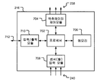
도 7은 본 발명의 일부 실시예들에 따른 제어기(216)의 예시적 구성을 도시한다. 도시된 바와 같이, 제어기(216)는 프로세서(702)를 포함할 수 있고, 프로세서(702)는, 메모리(706)에 저장될 수 있는 소프트웨어의 제어하에 동작하도록 구성된 프로세서(702)일 수 있다(본 명세서에서 사용될 때, 용어 "소프트웨어"는 제한없이 소프트웨어, 펌웨어, 마이크로코드, 또는 프로세서(702)와 같은 프로세서에 의해 실행될 수 있는 기타 임의의 머신 판독가능한 코드를 포함한다). 프로세서(702)와 메모리(706)는 소프트웨어 제어하에 동작하는 프로세서(702)와 동일하거나 유사한 기능을 수행하는 물리적으로 결선된 로직 회로로 대체될 수 있다. 또 다른 대안으로서, 프로세서(702)는, 물리적으로 결선된 로직을 포함할 수 있으며, 물리적으로 결선된 로직 및 소프트웨어의 제어하에 동작할 수 있다. 제어기(216)는 센서(224)들 중 하나 이상에 의해 출력된 하나 이상의 신호(240)들(3개가 도시되어 있지만, 더 많거나 더 적은 수의 신호가 사용될 수 있다)을 수신하도록 구성된 센서 입력 모듈(708)을 역시 포함할 수 있으며, 제어기(216)는 액츄에이터(215)에 하나 이상의 제어 신호(238)(3개가 도시되어 있지만, 더 많거나 더 적은 수의 신호가 사용될 수 있다)를 출력하도록 구성된 액츄에이터 제어 모듈(704)을 포함할 수 있다. 도시된 바와 같이, 제어기(216)는 다른 입력/출력 신호(712)들에 대해 일반적인 입력/출력 모듈(710)을 포함할 수 있다. 다른 모듈들과 특징들(미도시)도 역시 포함될 수 있다.7 illustrates an exemplary configuration of a controller 216 in accordance with some embodiments of the present invention. As shown, the controller 216 may include a processor 702, and the processor 702 may be a processor 702 configured to operate under the control of software that may be stored in the memory 706 ( As used herein, the term "software" includes, without limitation, software, firmware, microcode, or any other machine readable code that may be executed by a processor such as processor 702). Processor 702 and memory 706 may be replaced with physically wired logic circuitry that performs the same or similar functions as processor 702 operating under software control. As yet another alternative, the processor 702 may include physically wired logic and may operate under the control of physically wired logic and software. The controller 216 is configured to receive one or more signals 240 outputted by one or more of the sensors 224 (three are shown, although more or fewer signals may be used). Module 708 may also be included, and controller 216 outputs one or more control signals 238 (three are shown, although more or fewer signals may be used) to actuator 215. Actuator control module 704 may be configured to. As shown, the controller 216 may include an input / output module 710 that is generic for other input / output signals 712. Other modules and features (not shown) may also be included.

도 7은 단지 예를 위한 것이며, 제어기(216)의 임의의 다른 구성들도 가능하 다. 예를 들어, 제어기(216)는 공기압 컴퓨팅 시스템을 형성하도록 구성된 공기압 요소들을 포함할 수 있다.7 is for example only, and any other configurations of the controller 216 are possible. For example, controller 216 may include pneumatic elements configured to form a pneumatic computing system.

도 8은 본 발명의 일부 실시예들에 따라 제어기(216)에 의해 구현될 수 있는 예시적 프로세스(800)를 도시한다. 프로세스(800)는, 테스트 시스템(200)과 같은 테스트 시스템에서 DUT(230)와 같은 DUT의 테스팅 동안에 실행될 수 있다. 논의와 예시의 편의를 위해, 비록 프로세스(800)가 다른 테스트 시스템에서 다른 DUT의 테스팅 동안에 구현될 수 있지만, 프로세스(800)는 테스트 시스템(200)에서 DUT(230)의 테스팅에 관하여 설명될 것이다.8 illustrates an example process 800 that may be implemented by the controller 216 in accordance with some embodiments of the present invention. Process 800 may be executed during testing of a DUT, such as DUT 230, in a test system, such as test system 200. For convenience of discussion and example, although process 800 may be implemented during testing of another DUT in another test system, process 800 will be described with respect to testing of DUT 230 in test system 200. .

프로세스(800)가 구현될 수 있는 기간인 DUT(230)의 테스팅은 다음과 같이 구현될 수 있다. DUT(230)는 도 2의 테스트 시스템(200)의 하우징(212) 내의 홀더(232) 상에 배치될 수 있고, 홀더(232)는 DUT 단자(228)들을 프로브(226)들과 정렬시키기 위해 필요하다면, "x, y" 축을 따라 DUT(230)를 이동시킬 수 있다. 그 다음, 홀더(232)는 전술된 바와 같이 과이동 거리만큼 단자(228)들과 프로브(226)들 사이의 제1 접촉선을 넘어 프로브(226)들을 향하여 대체로 "z" 축을 따라 DUT(230)를 이동시킬 수 있다. 이 접촉은 프로브(226)들과 단자(228)들 사이에 전기 접속을 확립할 수 있다. 그 다음, 테스터는, 채널(204)과 프로브 카드 어셈블리(234)를 통해 DUT(230)에 제공되는 테스트 신호를 발생할 수 있다. 테스트 신호에 응답하여 DUT(230)에 의해 발생된 응답 신호는 프로브 카드 어셈블리(234)와 채널(204)을 통해 테스터(202)에 제공될 수 있다. 테스터(202)는, DUT(230)가 적절히 기능했는지의 여부를 판정하기 위해 그 응답 신호를 분석할 수 있다. 테스팅에 앞서, 테스트 시스템(200) 상에서 또는 그 내에서, 하나 이상의 초기화 프로시져(미도시)가 수행될 수 있고, 이와 같은 초기화 프로시져는, 감소된 속도에서 또는 전속력에서, 테스트 프로시져들의 초기 일부 또는 전체의 실행을 포함할 수 있다.Testing of the DUT 230, which is the period during which the process 800 can be implemented, can be implemented as follows. The DUT 230 may be placed on a holder 232 in the housing 212 of the test system 200 of FIG. 2, the holder 232 for aligning the DUT terminals 228 with the probes 226. If desired, the DUT 230 can be moved along the "x, y" axis. The holder 232 then crosses the DUT 230 along a generally "z" axis toward the probes 226 beyond the first contact line between the terminals 228 and the probes 226 by an overtravel distance as described above. ) Can be moved. This contact may establish an electrical connection between the probes 226 and the terminals 228. The tester may then generate a test signal provided to the DUT 230 via the channel 204 and the probe card assembly 234. The response signal generated by the DUT 230 in response to the test signal may be provided to the tester 202 via the probe card assembly 234 and the channel 204. Tester 202 may analyze the response signal to determine whether DUT 230 has functioned properly. Prior to testing, one or more initialization procedures (not shown) may be performed on or within test system 200, and such initialization procedures, at reduced speed or at full speed, may include some or all of the initial portions of the test procedures. It may include the execution of.

전술된 테스팅을 개시하기 이전에 또는 이후에, 제어기(216)는 프로세스(800)를 개시할 수 있고, 테스팅 동안에 프로세스(800)의 실행을 계속한다. (802)에서, 제어기(216)는 프로브 카드 어셈블리(234)에 관한 컴플라이언스 요구치를 모니터링할 수 있다. 제어기(216)는 센서(224)에 의해 발생된 출력 신호(240)를 이용하여 모니터링할 수 있다. (804)에서, 제어기(216)는 총 컴플라이언스 요구치의 일부를 액츄에이터(215)에 의한 프로브 헤드 어셈블리(222)의 이동에 할당할지의 여부를 판정할 수 있다. 즉, 제어기(216)는 프로브 헤드 어셈블리(222)를 이동시킴으로써 프로브(226)들에 부과된 총 컴플라이언스 요구치를 저감시킬지의 여부를 판정할 수 있다. 달리 말하자면, 액츄에이터(215)의 이동은, (컴플라이언스의 제1 소스를 제공한다고 말할 수 있는) 프로브(226)들과 더불어, 프로브 카드 어셈블리(234)에 부과된 총 컴플라이언스 요구치를 충족시킬 수 있는 컴플라이언스의 제2 소스를 제공할 수 있다.Before or after initiating the above-described testing, controller 216 may initiate process 800 and continue execution of process 800 during testing. At 802, controller 216 may monitor the compliance requirements for the probe card assembly 234. The controller 216 can monitor using the output signal 240 generated by the sensor 224. At 804, controller 216 can determine whether to allocate a portion of the total compliance requirement to movement of probe head assembly 222 by actuator 215. That is, the controller 216 can determine whether to reduce the total compliance requirement imposed on the probes 226 by moving the probe head assembly 222. In other words, the movement of the actuator 215, along with the probes 226 (which may be said to provide a first source of compliance), may meet the total compliance requirements imposed on the probe card assembly 234. It can provide a second source of.

제어기(216)는 몇가지 가능한 방식들 중 임의의 방식으로 단계(804)를 수행할 수 있다. 예를 들어, 제어기(216)는 컴플라이언스 요구치가 임계값을 초과하는지의 여부를 판정할 수 있다. 임계값은 프로브(226)들을 손상시키는 현저한 위험없이 프로브(226)들이 안전하게 충족시킬 수 있는 최대 컴플라이언스 요구치가 되도록 설정될 수 있다. 따라서, 임계값은 프로브(226)들의 설계와 구성, 프로 브(226)들을 구성하는 재료, 및 강도, 탄성, 복원력, 스프링값 등과 같은 프로브(226)들에 관한 기타의 파라미터들에 의존할 수 있다. 대안으로서 또는 추가적으로, 임계값은 프로브(226)들의 전기적 특성에 의존할 수 있다. 예를 들어, 임계값은 프로브(226)들의 하나 이상의 측정된 접촉 저항에 직접 또는 간접으로 의존할 수 있다.Controller 216 may perform step 804 in any of several possible ways. For example, the controller 216 can determine whether the compliance request exceeds a threshold. The threshold can be set to be the maximum compliance requirement that the probes 226 can safely meet without significant risk of damaging the probes 226. Thus, the threshold may depend on the design and configuration of the probes 226, the material making up the probes 226, and other parameters regarding the probes 226 such as strength, elasticity, resilience, spring value, and the like. have. Alternatively or additionally, the threshold may depend on the electrical properties of the probes 226. For example, the threshold may depend directly or indirectly on one or more measured contact resistances of the probes 226.

804에서 제어기(216)가 컴플라이언스를 할당할지의 여부를 어떻게 판정할 수 있는지의 또다른 예로서, 제어기(216)는 802에서 판정된 총 컴플라이언스 요구치의 미리결정된 퍼센트를 804에서 프로브(226)들에 할당하도록 구성될 수 있다. 총 컴플라이언스 요구치의 나머지 부분들은, 앞서 전반적으로 기술된 바와 같이, 프로브 헤드 어셈블리(222)의 이동에 할당될 수 있다. 또 다른 대안으로서, 제어기(216)는 총 컴플라이언스 요구치의 미리결정된 퍼센트를 프로브 헤드 어셈블리(222)의 이동에 할당할 수 있다. 역시 또 다른 대안으로서, 제어기(216)는, (804)에서, 미리결정된 레벨의 컴플라이언스를 프로브(226)들 또는 프로브 헤드 어셈블리(222)의 이동에 할당하도록 구성될 수 있고, (804)에서, 총 컴플라이언스 요구치의 나머지를 다른 프로브(226)들 또는 프로브 헤드 어셈블리(222)에 할당하도록 구성될 수 있다. 만일 제어기(216)가 총 컴플라이언스 요구치의 소정 퍼센트 또는 미리결정된 양을 프로브(226) 또는 프로브 헤드 어셈블리(222)의 이동에 할당하도록 구성된다면, 도 8의 프로세스(800)는 (804)에서 항상 "예" 판정에 따라 분기하도록 구성될 수 있다.As another example of how the controller 216 can determine whether to assign compliance at 804, the controller 216 sends the predetermined percentage of the total compliance request determined at 802 to the probes 226 at 804. Can be configured to assign. The remaining portions of the total compliance requirement may be assigned to the movement of the probe head assembly 222, as described above generally. As another alternative, the controller 216 may assign a predetermined percentage of the total compliance requirement to the movement of the probe head assembly 222. As yet another alternative, the controller 216 may be configured, at 804, to assign a predetermined level of compliance to the movement of the probes 226 or the probe head assembly 222, and at 804, It can be configured to assign the remainder of the total compliance requirement to other probes 226 or probe head assembly 222. If controller 216 is configured to allocate a predetermined percentage or predetermined amount of the total compliance requirement to the movement of probe 226 or probe head assembly 222, process 800 of FIG. Yes ", the branch may be configured to branch according to the determination.

만일 제어기(216)가 단계(802)에서 모니터링된 컴플라이언스 요구치를 할당 하기로 (804)에서 결정한다면, (806)에서 제어기(216)는, (802)에서 판정된 총 컴플라이언스 요구치를 프로브(226)들과 프로브 헤드 어셈블리(222)의 이동간에 할당하도록 프로브 헤드 어셈블리(222)를 이동시키기 위해, 액츄에이터(215)에 제어 신호(238)를 출력할 수 있다(그렇지 않은 경우 프로브(226)에 부과되는 컴플라이언스 요구치를 효과적으로 줄일 수 있다). 앞서 논의된 바와 같이, 따라서, 액츄에이터(215)는 프로브 헤드 어셈블리(222)를 이동시켜 프로브 카드 어셈블리(234)에 부과된 총 컴플라이언스 요구치의 일부를 제공하도록 구동될 수 있다. 따라서, 프로브(226)들은 프로브 카드 어셈블리(234)에 요구되는 총 컴플라이언스의 일부만을 제공할 필요가 있다. 도 6에 관하여 앞서 논의된 바와 같이, 프로브(226)는 (가상 스프링 602, 604의 합으로서 도 6에 도시되어 있는) 총 컴플라이언스 요구치의 일부(즉, 가상 스프링 604로 표시된 부분)만을 제공할 필요성이 있다. 이것은, 액츄에이터(215)들이 가상 스프링(602)으로 표시된 컴플라이언스의 일부를 제공할 수 있기 때문이다. 바꾸어 말하면, 액츄에이터(215)의 이동은, (컴플라이언스의 제1 소스를 제공한다고 말할 수 있는) 프로브(226)들과 함께, 프로브 카드 어셈블리(234)에 부과된 총 컴플라이언스 요구치를 충족시키는 컴플라이언스의 제2 소스를 제공할 수 있다.If the controller 216 determines at 804 to assign the compliance requirement monitored at step 802, the controller 216 at 806 determines the total compliance request determined at 802 by the probe 226. Control signal 238 can be output to actuator 215 (otherwise imposed on probe 226 to move probe head assembly 222 to assign between movement of the probe head assembly 222). Can effectively reduce compliance requirements). As discussed above, the actuator 215 can thus be driven to move the probe head assembly 222 to provide a portion of the total compliance requirement imposed on the probe card assembly 234. Thus, the probes 226 need only provide a portion of the total compliance required for the probe card assembly 234. As discussed above with respect to FIG. 6, the probe 226 needs to provide only a portion of the total compliance requirement (ie, the portion indicated as the virtual spring 604) (shown in FIG. 6 as the sum of the virtual springs 602, 604). There is this. This is because the actuators 215 may provide some of the compliance indicated by the virtual spring 602. In other words, the movement of actuator 215, together with probes 226 (which may be said to provide a first source of compliance), results in compliance of the total compliance requirements imposed on the probe card assembly 234. 2 sources can be provided.

도 8의 프로세스(800)를 다시 한번 참조하면, (808)에서, 프로세스(800)는 복귀하여 802, 804, 806을 반복할 수 있다. 이것은 임의 횟수만큼 반복될 수 있다. 대안으로서, (808)에서, 프로세스(800)는 종료할 수 있다. (808)에서 프로세스(800)를 종료할지의 여부를 판정하기 위해 임의 갯수의 기준이 사용될 수 있다. 예를 들어, 프로세스(800)는, 전술된 바와 같이, 프로브(226)들과의 초기 접촉을 지나 과이동 거리만큼 DUT 단자(228)들을 이동시킴으로써 프로브(226)들과 DUT 단자(228)들 사이에서 전기 접속이 확립된 후에, 종료할 수 있다. 이와 같은 경우, 액츄에이터(215)는 과이동을 흡수하는데 필요한 컴플라이언스의 일부를 제공하기 위해 사용될 수 있다.Referring again to process 800 of FIG. 8, at 808, process 800 may return to repeat 802, 804, 806. This can be repeated any number of times. Alternatively, at 808, process 800 can end. Any number of criteria may be used to determine whether to end process 800 at 808. For example, the process 800 may move the probes 226 and the DUT terminals 228 by moving the DUT terminals 228 by an overtravel distance past an initial contact with the probes 226, as described above. After the electrical connection is established between them, it can be terminated. In such cases, actuator 215 may be used to provide some of the compliance required to absorb overtravel.

또 다른 예로서, 프로세스(800)는 DUT(230)의 전체 테스팅을 계속할 수 있다. 따라서, 808에서의 종료 판정은 DUT(230)의 테스팅 종료와 일치할 수 있다. 이와 같은 경우에서, 프로세스(800) ―및 액츄에이터(215)― 는 프로브(226)와의 제1 접촉선을 지난 DUT 단자(228)의 과이동이 아닌 사건들에 응답하여 추가의 컴플라이언스를 제공할 수 있다. 예를 들어, 프로브 카드 어셈블리(234)를 가로지른 온도 경사도는 테스팅 동안에 바뀔 수 있고, 이것은 프로브 카드 어셈블리의 열적으로 유도된 이동(예를 들어, 뒤틀림)을 유발할 수 있고, 이것은 프로브 카드 어셈블리에 관한 컴플라이언스 요구치를 변경할 수 있다. 이와 같은 변경은 802 및 804에서 검출될 수 있고, 806에서 보상될 수 있다. 808에서 프로세스(800)의 종료에 대한 기준의 역시 또 다른 예로서, 808에서의 종료 판정은, 사용자가 중단 프로시져를 활성화할 때 생성되는 종료 신호와 같은 신호에 기초할 수 있다.As another example, process 800 may continue with full testing of DUT 230. Thus, the termination decision at 808 may coincide with the testing termination of the DUT 230. In such a case, process 800-and actuator 215-can provide additional compliance in response to non-overtravel events of DUT terminal 228 past the first contact with probe 226. have. For example, the temperature gradient across the probe card assembly 234 can change during testing, which can cause thermally induced movement (eg, distortion) of the probe card assembly, which is related to the probe card assembly. You can change the compliance requirements. Such a change can be detected at 802 and 804 and compensated at 806. As yet another example of a criterion for termination of process 800 at 808, the termination determination at 808 may be based on a signal, such as an termination signal generated when the user activates the abort procedure.

제어기(216)가 802에서 컴플라이언스 요구치를 모니터링하고, 804에서 컴플라이언스 요구치의 일부를 액츄에이터(215)에 할당할지의 여부를 판정하고, 806에서 컴플라이언스 요구치를 할당하기 위해 액츄에이터(215)를 구동하는 임의 갯수의 방식들이 있다. 도 9a-12b는 비제한적 예들을 도시한다.The controller 216 monitors the compliance request at 802, determines at 804 whether or not to assign a portion of the compliance request to the actuator 215, and drives any number of actuators 215 to assign the compliance request at 806. There are ways of doing this. 9A-12B show non-limiting examples.

도 9a 및 9b는 압축 거리 대 힘의 예시적 그래프를 도시한다. 이것은 도 8의 프로세스(800)의 802, 804, 806을 실행하는데 있어서 제어기(216)의 예시적 동작을 나타낼 수 있다.9A and 9B show exemplary graphs of compression distance versus force. This may represent exemplary operation of the controller 216 in executing 802, 804, 806 of process 800 of FIG. 8.

도 9a에서, 수직축(830)(압축 거리라고 라벨링됨)은 프로브(226)가 압축된 거리를 나타낼 수 있고, 수평축(832)(힘이라고 라벨링됨)은 프로브(226) 상의 대응하는 힘을 나타낼 수 있다. 라인 세그먼트(833)는 대체로 후크의 법칙(예를 들어, f = k*d, f는 프로브(226)에 인가되는 힘이고, k는 프로브(226)의 스프링 상수이고, d는 (축 830을 따른) 압축 거리이며, *는 곱셈을 나타낸다)에 따른 프로브(226)의 전형적인 응답을 나타낼 수 있다. 도 10은 한 예를 도시한다. 도 10에 예시된 바와 같이, (도 10에는 라인으로 개략적으로 도시되어 있지만, 실제적 실시에서는 많은 실제적 형상을 취할 수 있는) 프로브(226)들은, 그들의 끝부분(예를 들어, 첨두부)이 라인 d0로 표시된 평면 또는 근사 평면(라인 d0에 대응하는 평면은 도 10의 지면 안팎으로 연장될 수 있다)에 위치해 있으면서, 압축되지 않은 상태로 도시되어 있다. 도 10에서, 압축된 상태의 프로브(226)들은 그들의 끝부분이 라인 d1로 표시된 평면 또는 근사 평면(d1에 대응하는 평면은 도 10의 지면 안팎으로 연장될 수 있다)에 위치해 있으면서, 점선으로 도시되어 있다. 도 10에서 거리 d1은 도 9a에서 수직축(830)에 대응하는 압축 거리 d1일 수 있으며, 프로브(226) 상의 결과적인 힘은 도 9a의 수평축(832)에 대응하는 힘 f1일 수 있다.In FIG. 9A, the vertical axis 830 (labeled compression distance) may represent the distance the probe 226 is compressed, and the horizontal axis 832 (labeled force) may represent the corresponding force on the probe 226. Can be. Line segment 833 is generally Hook's Law (e.g., f = k * d, f is the force applied to probe 226, k is the spring constant of probe 226, and d is the axis 830 Compression distance, * denotes multiplication). 10 shows an example. As illustrated in FIG. 10, the probes 226 (shown schematically in lines in FIG. 10, but that can take many practical shapes in practical implementation) have their ends (eg, peaks) lined up. d 0 plane or near the plane indicated by the stay is located in (a plane corresponding to the line d 0 may be extended to the ground and out of Fig. 10) is shown in an uncompressed state. In FIG. 10, the probes 226 in a compressed state are dotted with their ends positioned in the plane indicated by the line d 1 or in an approximate plane (the plane corresponding to d 1 may extend in and out of the ground of FIG. 10). Is shown. In FIG. 10, the distance d 1 may be the compression distance d 1 corresponding to the vertical axis 830 in FIG. 9A, and the resulting force on the probe 226 may be the force f 1 corresponding to the horizontal axis 832 of FIG. 9A. .

한 비제한적 예에서, 제어기(216)는 도 9a에 도시된 라인 세그먼트(835)에 따라 도 8의 프로세스(800)의 802, 804, 806을 실행하도록 프로그램될 수 있다. 프로브 또는 프로브(226)들 상의 힘이 도 9a의 fon으로 라벨링된 힘보다 작은 동안, 제어기(216)는 액츄에이터(215)를 구동하지 않도록 구성될 수 있고, 프로브(226)들은 대체로 후크의 법칙에 따라(예를 들어, 라인 세그먼트(833)에 따라) 대체로 스프링처럼 행동할 수 있다. 즉, 프로브 또는 프로브(226)들 상의 힘이 도 9a의 fon으로 라벨링된 힘보다 작은 동안, 프로브(226)들의 압축 거리와 프로브(226)들 상에서의 그 결과적인 힘은, 라인 세그먼트(833)에 의해 도시된 바와 같이 서로 비례하여 변경될 수 있다. 그러나, 일단 프로브(226)들 중 하나 이상에서의 힘이 fon을 초과하면, 제어기(216)는 프로브 헤드 어셈블리(222)를 이동시키기 위해 액츄에이터(215)를 구동하도록 구성될 수 있다. 도 9a에 도시된 예에 따라, 제어기(216)는 라인 세그먼트(835)에 따라 액츄에이터(215)를 구동하도록 구성될 수 있다.In one non-limiting example, controller 216 may be programmed to execute 802, 804, 806 of process 800 of FIG. 8 in accordance with line segment 835 shown in FIG. 9A. While the force on the probe or probes 226 is less than the force labeled f on in FIG. 9A, the controller 216 may be configured to not drive the actuator 215, and the probes 226 may generally be hook's law. Depending on (eg, along line segment 833) it can generally act like a spring. That is, while the force on the probe or probes 226 is less than the force labeled f on in FIG. 9A, the compression distance of the probes 226 and the resulting force on the probes 226 are line segment 833. It can be changed in proportion to each other as shown by. However, once the force at one or more of the probes 226 exceeds f on , the controller 216 can be configured to drive the actuator 215 to move the probe head assembly 222. According to the example shown in FIG. 9A, controller 216 may be configured to drive actuator 215 along line segment 835.

전술된 내용의 한 예가 도 11a 및 11b에 도시되어 있다. 프로브(226)들이 압축 거리 d0(즉, 무압축)로부터 압축 거리 don으로 압축될 때, 프로브(226)들은 도 11a에 도시된 바와 같이 후크의 법칙에 따라(예를 들어, 도 9a의 라인 세그먼트(833)에 따라) 스프링처럼 압축된다. 도 11b에 도시된 바와 같이, 만일 프로브(226)들 상의 힘이 fon을 초과하면, 제어기(216)는 액츄에이터(215)를 제어할 수 있고, 액츄에이터(215)가 압축의 방향으로 프로브 헤드 어셈블리(222)를 이동시키 도록 유발한다. 도 11b에서, 프로브 헤드 어셈블리(222)는 초기 위치 H0로부터 위치 H1으로 이동된다.One example of the foregoing is shown in FIGS. 11A and 11B. When the probes 226 are compressed from the compression distance d 0 (ie, no compression) to the compression distance d on , the probes 226 are in accordance with the law of the hook as shown in FIG. 11A (eg, in FIG. 9A). Compressed according to line segment 833). As shown in FIG. 11B, if the force on the probes 226 exceeds f on , the controller 216 may control the actuator 215, and the actuator 215 may move the probe head assembly in the direction of compression. Cause 222 to move. In FIG. 11B, the probe head assembly 222 is moved from the initial position H 0 to the position H 1 .

도 9b는, 프로브(226)에 맞대어 압축된 DUT(예를 들어, DUT(230))의 관점으로부터의 액츄에이터(215)의 동작과 프로브(226)들의 결합된 응답을 예시한다. 도 9b에서, 복합선(837)은 도 9a의 라인 세그먼트들(833 및 835)의 합계를 나타낼 수 있다. 도 9a의 라인 세그먼트(835)의 830 축값이 fon보다 작은 힘에 대해 0이기 때문에, 도 9b의 복합선(837)의 제1 세그먼트(834)는 도 9a의 라인 세그먼트(833)에 대응하고, 프로브(226)들 자체의 응답에 대응한다. 복합선(837)의 제2 세그먼트(836)는 도 9a의 라인 세그먼트들(833 및 835)의 합이고, 도 9a의 라인 세그먼트(835)에 따른 액츄에이터(215)의 동작과 도 9a의 라인 세그먼트(833)에 따른 프로브(226)들의 결합된 응답을 나타낸다. 도 9b에 도시된 특정의 비제한적 예에서, 라인 세그먼트(835)의 경사도(즉, 환언하면, 액츄에이터(215)의 제어)는 fon을 넘어선 프로브(226)들 상에서의 힘의 임의의 증가분의 거의 전부가, 프로브(226)들의 압축 방향으로의 프로브 헤드 어셈블리(222)의 대응하는 이동에 의해 상쇄되어, 프로브(226)들 상의 힘이 겨우 약간만 증가하여, 프로브 상에서의 일정한 힘으로 근사화될 수 있도록 선택될 수 있다. 그러나, 라인 세그먼트(835)에 대해 다른 경사도가 선택될 수 있고, 이것은 복합선(837)의 제2 세그먼트(836)에 대하여 상이한 대응하는 경사도를 초래할 수 있다.9B illustrates the combined response of the probes 226 with the operation of the actuator 215 from the perspective of the compressed DUT (eg, DUT 230) against the probe 226. In FIG. 9B, compound line 837 may represent the sum of line segments 833 and 835 of FIG. 9A. Since the 830 axis value of the line segment 835 of FIG. 9A is zero for a force less than f on , the first segment 834 of the composite line 837 of FIG. 9B corresponds to the line segment 833 of FIG. 9A and Corresponding to the response of the probes 226 themselves. The second segment 836 of the composite line 837 is the sum of the line segments 833 and 835 of FIG. 9A, the operation of the actuator 215 according to the line segment 835 of FIG. 9A and the line segment of FIG. 9A. The combined response of the probes 226 according to 833 is shown. In the particular non-limiting example shown in FIG. 9B, the slope of the line segment 835 (ie, control of the actuator 215) is one of any increase in force on the probes 226 beyond f on . Almost all can be offset by the corresponding movement of the probe head assembly 222 in the compression direction of the probes 226 such that the force on the probes 226 can only be slightly increased, approximating to a constant force on the probe. Can be selected to. However, other slopes may be selected for the line segment 835, which may result in different corresponding slopes for the second segment 836 of the composite line 837.

액츄에이터(215)의 예시적 제어를 도시하는 (도 9a의 라인 세그먼트(835)로 나타낸) 함수는 단지 예시적인 것이며, 많은 다른 함수들이 라인 세그먼트(835)로 표시된 함수를 대체할 수 있다. 도 12a 및 12b는 액츄에이터(215)의 제어를 (제1 세그먼트(1204)와 제2 세그먼트(1206)를 포함하는, 도 12a의 복합선 1202로 표시된) 복합 함수로 표시한 예를 도시한다. 도 12a에서, 라인 세그먼트(833)는 도 9a에서와 같고, 전술된 바와 같이 후크의 법칙에 따라 프로브(226)들 자체의 응답을 나타낸다.The function (shown by line segment 835 of FIG. 9A) illustrating exemplary control of actuator 215 is merely exemplary, and many other functions may replace the function indicated by line segment 835. 12A and 12B show an example in which the control of actuator 215 is represented by a composite function (indicated by composite line 1202 in FIG. 12A, including first segment 1204 and second segment 1206). In FIG. 12A, line segment 833 is the same as in FIG. 9A, and represents the response of the probes 226 itself in accordance with Hook's Law as described above.

도 12a의 (전술된 바와 같이, 액츄에이터(215)의 제어를 나타내는) 복합선(1202)을 참조하면, 프로브(226)들 상의 힘이 fon보다 작은 동안, 제어기(216)는 액츄에이터(215)를 활성화하지 않도록 구성될 수 있다. 프로브(226) 상의 힘이 fon과 f1 사이에 있는 동안, 제어기(216)는 제1 세그먼트(1204)에 따라 프로브 헤드 어셈블리(222)를 이동시키게끔 액츄에이터(215)를 제어하도록 구성될 수 있다. 예를 들어, 제어기(216)는, 프로브(226)들 상의 힘 fΔ1에서의 매 단위 변경에 대해 dΔ1에 대응하는 거리만큼 프로브 헤드 어셈블리(222)를 이동시키도록 구성될 수 있다. 프로브(226)들 상의 힘이 f1보다 큰 동안, 제어기(216)는 제2 세그먼트(1206)에 따라 액츄에이터(215)를 제어하도록 구성될 수 있다. 예를 들어, 제어기(216)는 프로브(226)들 상의 힘 fΔ2에서의 매 단위 변경에 대해 dΔ2에 대응하는 거리만큼 프로브 헤드 어셈블리(222)를 이동시키도록 구성될 수 있다.Referring to the composite line 1202 (representing control of the actuator 215, as described above) in FIG. 12A, while the force on the probes 226 is less than f on , the controller 216 may actuate the actuator 215. Can be configured to not activate. While the force on the probe 226 is between f on and f 1 , the controller 216 may be configured to control the actuator 215 to move the probe head assembly 222 according to the first segment 1204. have. For example, the controller 216 may be configured to move the probe head assembly 222 by a distance corresponding to d Δ1 for every unit change in force f Δ1 on the probes 226. While the force on the probes 226 is greater than f 1 , the controller 216 may be configured to control the actuator 215 according to the second segment 1206. For example, the controller 216 may be configured to move the probe head assembly 222 by a distance corresponding to d Δ2 for every unit change in force f Δ2 on the probes 226.

도 12b는 프로브(226)에 맞대어 압축된 DUT(예를 들어, DUT(230))의 관점으 로부터 액츄에이터(215)의 동작과 프로브(226)들의 결합된 응답을 도시한다. 도 12b에서, 복합선(1208)은, 도 12a의 라인 세그먼트(833)와 복합선(1202)의 합을 나타낼 수 있다. 도 12a의 복합선(1202)의 830 축값은 fon보다 작은 힘에 대해 0이기 때문에, 도 12b의 복합선(1208)의 제1 세그먼트(1210)는 도 12a의 라인 세그먼트(833)에 대응할 수 있고, 이것은, 전술한 바와 같이, 프로브(226)들 자체의 응답에 대응할 수 있다. 복합선(1208)의 제2 세그먼트(1212)는 도 12a의 제1 세그먼트(1204)와 라인 세그먼트(833)의 합계일 수 있으며, 힘이 fon과 f1 사이에 있는 동안 도 12a의 제1 세그먼트(1204)에 따른 액츄에이터(215)의 동작과 도 12a의 라인 세그먼트(833)에 따른 프로브(226)들의 결합된 응답을 나타낼 수 있다. 복합선(1208)의 제3 세그먼트(1214)는 도 12a의 제2 세그먼트(1206)와 라인 세그먼트(833)의 합계일 수 있으며, 힘이 f1보다 큰 동안 도 12a의 제2 세그먼트(1206)에 따른 액츄에이터(215)의 동작과 도 12a의 라인 세그먼트(833)에 따른 프로브(226)들의 결합된 응답을 나타낼 수 있다.12B shows the combined response of the probes 226 with the operation of the actuator 215 from the perspective of the compressed DUT (eg, DUT 230) against the probe 226. In FIG. 12B, compound line 1208 may represent the sum of line segment 833 and compound line 1202 in FIG. 12A. Since the 830 axis value of the composite line 1202 of FIG. 12A is zero for a force less than f on , the first segment 1210 of the composite line 1208 of FIG. 12B may correspond to the line segment 833 of FIG. 12A. This may correspond to the response of the probes 226 themselves, as described above. The second segment 1212 of the compound line 1208 may be the sum of the first segment 1204 and the line segment 833 of FIG. 12A, while the force is between f on and f 1 . The combined response of the probes 226 along the line segment 833 of FIG. 12A and the operation of the actuator 215 along the segment 1204 can be shown. The third segment 1214 of the composite line 1208 may be the sum of the second segment 1206 and the line segment 833 of FIG. 12A, while the second segment 1206 of FIG. 12A while the force is greater than f 1 . And the combined response of the probes 226 according to the line segment 833 of FIG. 12A.

(제한없이 지수 함수를 포함한) 많은 다른 함수들이, 도 9a의 라인 세그먼트(835) 또는 도 12a의 복합선(1202)으로 표시된 함수를 대체할 수 있다.Many other functions (including but not limited to exponential functions) may replace the function indicated by line segment 835 of FIG. 9A or composite line 1202 of FIG. 12A.

도 9-12b에 도시된 예에서, 도 8의 프로세스(800)의 802, 804, 806은 전체로서 프로브 헤드 어셈블리(222)에 관하여 수행될 수 있다. 대안으로서, 프로세스(800)의 802, 804, 806은 프로브 헤드 어셈블리(222)의 복수의 섹터들에 관하여 개별적으로 수행될 수 있다. 예를 들어, 도 15a 및 15b에 관하여 이하에서 논의되 는 바와 같이, 프로브 헤드 어셈블리(222)는 섹터들로 분할될 수 있고, 센서 또는 센서들(224) 및 액츄에이터 또는 액츄에이터(215)들이 각각의 섹터에 대해 제공될 수 있다. 알 수 있는 바와 같이, 도 15는, 프로브(226)들이 부착되는 프로브 헤드 어셈블리(222)의 표면이 섹터들(1102, 1104, 1106, 1108)로 분할될 수 있고 (도 15a 및 도 15b에는 4개가 도시되어 있지만, 표면은 더 많거나 더 적은 수의 섹터들로 분할될 수 있다); 각각의 섹터(1102, 1104, 1106, 1108)에 대해서 센서(224)가 제공될 수 있으며; 각각의 섹터(1102, 1104, 1106, 1108)에 대해서 구동 메커니즘(220)이 역시 제공될 수 있는, 비제한적 예를 도시하고 있다. 이와 같은 경우, 도 8의 프로세스(800)의 802, 804, 806은 각각의 섹터(1102, 1104, 1106, 1108)에 대해 개별적으로 및 동시에 수행될 수 있다.In the example shown in FIGS. 9-12B, 802, 804, and 806 of the process 800 of FIG. 8 may be performed with respect to the probe head assembly 222 as a whole. Alternatively, 802, 804, 806 of process 800 may be performed separately with respect to a plurality of sectors of probe head assembly 222. For example, as discussed below with respect to FIGS. 15A and 15B, the probe head assembly 222 may be divided into sectors, in which the sensor or sensors 224 and the actuator or actuators 215 may be separated from each other. May be provided for a sector. As can be seen, FIG. 15 shows that the surface of the probe head assembly 222 to which the probes 226 are attached can be divided into sectors 1102, 1104, 1106, 1108 (4 in FIGS. 15A and 15B). Dog is shown, the surface may be divided into more or fewer sectors); A sensor 224 may be provided for each sector 1102, 1104, 1106, 1108; A non-limiting example is shown in which drive mechanism 220 may also be provided for each sector 1102, 1104, 1106, 1108. In such a case, 802, 804, 806 of process 800 of FIG. 8 may be performed separately and simultaneously for each sector 1102, 1104, 1106, 1108.

도 13a-14b 및 도 16a-18b는 도 8의 프로세스(800)의 802, 804, 806의 몇개의 비제한 추가적 예 또는 동작을 도시하고 있다. 예시의 편의를 위해, 도 13a-14b 및 16a-17b에서, 프로브 카드 어셈블리(234)는 부분도로서 도시되어 있다. 더 구체적으로, 장착 구조물(236)이 부분도로 도시되어 있고, 가요성 전기 커넥터(218) 및 배선 기판(208)은 도시되어 있지 않다. 제어기(216) 및 신호(238 및 240)도 역시 도시되어 있지 않다.13A-14B and 16A-18B illustrate some non-limiting additional examples or operations of 802, 804, 806 of process 800 of FIG. 8. For convenience of illustration, in FIGS. 13A-14B and 16A-17B, the probe card assembly 234 is shown as a partial view. More specifically, mounting structure 236 is shown in partial views, and flexible electrical connector 218 and wiring board 208 are not shown. Controller 216 and signals 238 and 240 are also not shown.

도 13a 및 도 13b는, 도 8의 프로세스(800)에 관하여 전술한 바와 같이, 제어기(216)가 802에서 컴플라이언스 요구치를 모니터링할 수 있고, 804에서 컴플라이언스 요구치의 일부를 액츄에이터(215)에 할당할지의 여부를 판정하며, 806에서 컴플라이언스 요구치를 할당하기 위해 액츄에이터(215)를 구동하는, 본 발명의 일 부 실시예들에 따른 예시적 방식을 도시하고 있다. 도 13a 및 13b에서, 센서(224)(비록 한개의 센서가 도시되어 있지만, 더 많은 센서들이 이용될 수 있다)는, 프로브(226)들 중 하나 이상에서의 힘의 양을 검출하도록 구성된 스트레인 게이지를 포함할 수 있다. 제어기(216)는, 센서(224)에 의해 출력되며 프로브(226) 상의 힘의 레벨에 비례하거나 함수적으로 관련될 수 있는(예를 들어, 출력은 힘의 레벨에 선형적으로 비례하지 않을 수도 있다) 신호(240)(도 2 참조)를 수신함으로써 도 8의 802를 실행할 수 있다. 제어기(216)는, 804에 관하여 전술된 방식들 중 임의의 방식으로 804를 실행할 수 있다. 예를 들어, 제어기(216)는, 802에서 판정된 총 컴플라이언스 요구치가 미리결정된 임계치를 초과하는지의 여부를 판정하도록 구성될 수 있다. 한 예에서, 제어기(216)는, 신호(240)에 의해 표시된 힘의 레벨을 메모리(706)(도 7 참조)에 저장된 임계치 힘과 비교함으로써 도 8의 804를 실행할 수 있다. 임계치 힘은 프로브(226)들에 안전하게 인가될 수 있는 최대치 힘, 즉, 프로브(226)들을 손상시키는 현저한 위험없이 프로브(226)들에 인가될 수 있는 최대치 힘으로서 미리 선택될 수 있다. 이와 같은 최대치 힘은, 프로브들의 알려진 설계 파라미터들에 기초한 계산을 통해 실험실 환경에서 프로브들을 테스팅하거나, 또는 기타의 방식으로 결정될 수 있다. 804에서 총 컴플라이언스 요구치를 할당할지의 여부를 제어기(216)가 판정할 수 있는 방법의 또 다른 예로서, 제어기(216)는, 802에서 판정된 총 컴플라이언스 요구치의 고정된 퍼센트를 804에서 프로브(206)들에 할당하도록 구성될 수 있다. 또 다른 예시적 대안으로서, 제어기(216)는 총 컴플라이언스 요구치의 고정된 퍼센트를 프로브 헤드 어셈블리(222) 의 이동에 할당하도록 구성될 수 있다. 달리 말하면, 제어기(216)는, 804에서, 컴플라이언스의 미리결정된 레벨을 프로브(226)들 또는 프로브 헤드 어셈블리(222)의 이동에 할당하고, 804에서, 총 컴플라이언스 요구치의 나머지를 다른 프로브(226)들 또는 프로브 헤드 어셈블리(222)에 할당하도록 구성될 수 있다.13A and 13B show that, as discussed above with respect to process 800 of FIG. 8, controller 216 may monitor compliance requirements at 802 and assign a portion of the compliance requirements to actuator 215 at 804. And at 806, an exemplary manner in accordance with some embodiments of the present invention for driving actuator 215 to assign a compliance requirement. In FIGS. 13A and 13B, a sensor 224 (although one sensor is shown, but more sensors may be used) is a strain gauge configured to detect the amount of force at one or more of the probes 226. It may include. Controller 216 is output by sensor 224 and may be proportional to or functionally related to the level of force on probe 226 (eg, the output may not be linearly proportional to the level of force). 802 of FIG. 8 may be executed by receiving the signal 240 (see FIG. 2). The controller 216 can execute 804 in any of the ways described above with respect to 804. For example, the controller 216 may be configured to determine whether the total compliance request determined at 802 exceeds a predetermined threshold. In one example, the controller 216 can execute 804 of FIG. 8 by comparing the level of force indicated by the signal 240 with the threshold force stored in the memory 706 (see FIG. 7). The threshold force may be preselected as the maximum force that can be safely applied to the probes 226, that is, the maximum force that can be applied to the probes 226 without significant risk of damaging the probes 226. This maximum force can be determined, or otherwise determined, in testing the probes in a laboratory environment through calculations based on known design parameters of the probes. As another example of how the controller 216 may determine whether to assign a total compliance request at 804, the controller 216 may provide a fixed percentage of the total compliance request determined at 802 with the probe 206. Can be configured to assign As another example alternative, the controller 216 may be configured to assign a fixed percentage of the total compliance requirement to the movement of the probe head assembly 222. In other words, the controller 216 assigns, at 804, the predetermined level of compliance to the movement of the probes 226 or the probe head assembly 222, and at 804, the remainder of the total compliance requirement is determined by the other probe 226. Or to the probe head assembly 222.

도 13a 및 13b에 도시된 예에서, 제어기(216)는, 802에서 판정된 총 컴플라이언스 요구치의 일부를 프로브 헤드 어셈블리(222)의 이동에 할당하기에 충분히 (도 13b에 도시된 바와 같이) DUT(230)로부터 멀어지는 방향으로 프로브 헤드 어셈블리(222)를 액츄에이터(215)가 이동시키도록 유발하는 제어 신호(238)를 806에서 출력할 수 있다. 예를 들어, 만일 제어기가, 총 컴플라이언스 요구치가 임계치를 초과한다고 판정함으로써 총 컴플라이언스 요구치를 할당하기로 804에서 판정한다면, 제어기(216)는 액츄에이터(215)가 프로브(226) 상의 힘을 임계치 힘까지 저감시키도록 유발하는 제어 신호(238)를 806에서 출력할 수 있다. 제어기(216)는 이것을, 프로브(226) 상의 힘이 임계치 힘 레벨이거나 그보다 작다고 제어기(216)가 판정할 때까지 엔진(214)으로 하여금 프로브 헤드 어셈블리(222)를 이동시키게 함으로써 행할 수 있다. 대안으로서, 제어기(216)는 프로브(226) 상의 힘을 임계치까지 저감시키기 위해 프로브 헤드 어셈블리(222)가 이동할 수 있는 거리를 계산하고, 엔진(214)으로 하여금 그 거리만큼 프로브 헤드 어셈블리(222)를 이동시키도록 유발할 수 있다. 이와 같은 계산은, 프로브들의 스프링 상수와 같은, 프로브(226)들의 파라미터를 이용하여 이루어질 수 있다. 만일 804에서의 판정이 총 컴플라이언스 요구치가 임계치를 초과하는지의 여부가 아닌 다른 기준(예를 들어, 전술된 대안적 기술들 중 임의의 기술)에 기초하여 이루어진다면, 제어기(216)는, 그 기준에 관련된 파라미터 또는 파라미터들이 충족될때까지 (도 13b에 도시된 바와 같은) DUT(230)로부터 멀어지는 방향으로 액츄에이터(215)가 프로브 헤드 어셈블리(222)를 이동시키도록 유발하는 제어 신호(238)를 806에서 출력할 수 있다.In the example shown in FIGS. 13A and 13B, the controller 216 is sufficient to allocate a portion of the total compliance requirement determined at 802 to movement of the probe head assembly 222 (as shown in FIG. 13B). A control signal 238 can be output at 806 that causes the actuator 215 to move the probe head assembly 222 in a direction away from 230. For example, if the controller determines at 804 to assign the total compliance request by determining that the total compliance request exceeds the threshold, the controller 216 causes the actuator 215 to force the force on the probe 226 to the threshold force. The control signal 238 can be output at 806 causing it to be reduced. The controller 216 can do this by having the engine 214 move the probe head assembly 222 until the controller 216 determines that the force on the probe 226 is at or below the threshold force level. Alternatively, the controller 216 calculates the distance that the probe head assembly 222 can move to reduce the force on the probe 226 to a threshold, and causes the engine 214 to probe head assembly 222 by that distance. May be caused to move. Such a calculation may be made using a parameter of the probes 226, such as a spring constant of the probes. If the determination at 804 is made based on a criterion other than whether the total compliance requirement exceeds a threshold (eg, any of the alternative techniques described above), the controller 216 may determine that criterion. 806 generates a control signal 238 that causes the actuator 215 to move the probe head assembly 222 in a direction away from the DUT 230 (as shown in FIG. 13B) until a parameter or parameters related to? Can be output from

도 13a 및 도 13b의 센서(224)는 프로브(226) 상의 힘의 레벨을 검출하도록 구성된 스트레인 게이지가 아닌 다른 것일 수 있다. 예를 들어, 센서(224)는 프로브 헤드 어셈블리(222)와 DUT(230) 사이의 거리를 검출하도록 구성될 수 있다. 이 거리는 프로브(226)들 상의 힘을 판정하거나 근사화하는데 사용될 수 있다. 프로브 헤드 어셈블리(222)와 DUT 사이의 거리를 검출하기 위한 적절한 센서(224)들의 예로는, 제한없이, 용량성 센서, 에어 게이지(갭) 센서, 선형 가변 변위 트랜스듀서, 및 유도성 센서가 포함된다.The sensor 224 of FIGS. 13A and 13B may be other than a strain gauge configured to detect the level of force on the probe 226. For example, the sensor 224 can be configured to detect the distance between the probe head assembly 222 and the DUT 230. This distance can be used to determine or approximate the force on the probes 226. Examples of suitable sensors 224 for detecting the distance between the probe head assembly 222 and the DUT include, without limitation, capacitive sensors, air gauge (gap) sensors, linear variable displacement transducers, and inductive sensors. do.

도 14a 및 도 14b는, 도 8의 프로세스(800)에 관하여 전술된 바와 같이, 제어기(216)가 802에서 컴플라이언스 요구치를 모니터링할 수 있고, 804에서 컴플라이언스 요구치의 일부를 액츄에이터(215)에 할당할지의 여부를 판정하고, 806에서 그 컴플라이언스 요구치를 할당하기 위해 액츄에이터(215)를 구동하는, 본 발명의 일부 실시예들에 따른 또다른 예시적 방법을 도시한다. 도 14a 및 도 14b에서, 센서(224)는 복수의 센서를 포함할 수 있고, 복수의 센서는, 프로브 헤드 어셈블리(222) 상의 다양한 위치들에 배치되고 프로브 헤드 어셈블리 상의 다양한 위치들에서의 프로브(226)들의 하나 이상에서의 힘의 양 또는 프로브(226)들의 하나 이상의 변위를 검출하도록 구성된다. 적절한 센서들의 예로서는, 도 13a 및 도 13b에 관하여 전술된 센서(224)에 대한 예들 중 임의의 것이 포함된다. 대안으로서 또는 추가적으로, 프로브(226)들 중 하나 이상이 센서로서 구성될 수 있다.14A and 14B show that, as described above with respect to process 800 of FIG. 8, controller 216 may monitor compliance requirements at 802 and assign a portion of the compliance requirements to actuator 215 at 804. And another exemplary method in accordance with some embodiments of the present invention for determining whether or not to drive actuator 215 to assign its compliance requirement at 806. 14A and 14B, the sensor 224 may include a plurality of sensors, wherein the plurality of sensors are disposed at various locations on the probe head assembly 222 and the probes at various locations on the probe head assembly. And to detect an amount of force in one or more of the 226 or one or more displacements of the probes 226. Examples of suitable sensors include any of the examples for sensor 224 described above with respect to FIGS. 13A and 13B. Alternatively or additionally, one or more of the probes 226 can be configured as a sensor.

제어기(216)는, 프로브 헤드 어셈블리(222) 상의 다양한 위치들에서의 프로브(226)들 상의 힘의 레벨 또는 프로브(226)들의 변위에 비례하는, 센서(224)들에 의해 출력된 (도 2 참조) 신호(240)를 수신함으로써 도 8의 802를 실행할 수 있다. 제어기(216)는 프로브 헤드 어셈블리(222) 상의 다양한 위치들에서의 힘 또는 변위에서의 불균형이 임계치 불균형을 초과하는 때를 판정함으로써 도 8의 804를 실행할 수 있다. 도 14a 및 11b에 도시된 예에서, 제어기(216)는, (도 14b에 도시된 바와 같이) 힘 또는 변위를 균형잡기 위해 장착 구조물(236)에 관하여 프로브 헤드 어셈블리(222)의 배향(예를 들어, 기울기)을 엔진(214)이 변경하도록 유발하는 제어 신호(238)를 806에서 출력할 수 있다.The controller 216 is output by the sensors 224, which is proportional to the level of force on the probes 226 or the displacement of the probes 226 at various locations on the probe head assembly 222 (FIG. 2). 802 of FIG. 8 may be executed by receiving the signal 240. The controller 216 can execute 804 of FIG. 8 by determining when an imbalance in force or displacement at various locations on the probe head assembly 222 exceeds a threshold imbalance. In the example shown in FIGS. 14A and 11B, the controller 216 is configured to provide an orientation (eg, an orientation of the probe head assembly 222 relative to the mounting structure 236 to balance the force or displacement (as shown in FIG. 14B). For example, a control signal 238 can be output at 806 causing the engine 214 to change the tilt).

도 13a, 13b와, 도 14a, 14b의 예들은 결합될 수 있다. 이와 같은 조합에서, 제어기(216)는 도 14a 및 도 14b에 관하여 전술된 바와 같은 프로브 헤드 어셈블리(222) 상의 다양한 위치들에서의 프로브(226)들 상의 힘을 802에서 모니터링할 수 있다. 804에서, 제어기(216)는 도 13a 및 도 13b에 관하여 전술된 바와 같이 힘들 중 임의의 힘이 임계치를 초과하는지의 여부를 판정할 수 있다. 그리고, 제어기(216)는 또한, 프로브 헤드 어셈블리(222) 상의 다양한 위치들에서의 프로브(226)들 상의 힘들에서의 불균형이 도 14a 및 도 14b에 관하여 전술된 바와 같이 임계치를 초과하는지의 여부를 판정할 수 있다. 806에서, 제어기(806)는, 도 13a 및 13b에 관하여 전술된 바와 같이 힘을 임계치까지(또는 임계치보다 작게) 저감시 키고 도 14a 및 도 14b와 관련하여 전술된 바와 같이 힘을 균형잡기 위해 필요하다면 엔진(214)으로 하여금 액츄에이터(215)를 이동시키도록 유발하는 제어 신호(238)를 출력할 수 있다.13A and 13B and the examples of FIGS. 14A and 14B may be combined. In such a combination, the controller 216 may monitor the force on the probes 226 at various locations on the probe head assembly 222 as described above with respect to FIGS. 14A and 14B. At 804, the controller 216 may determine whether any of the forces exceed the threshold as described above with respect to FIGS. 13A and 13B. In addition, the controller 216 also determines whether an imbalance in the forces on the probes 226 at various locations on the probe head assembly 222 exceeds a threshold as described above with respect to FIGS. 14A and 14B. It can be determined. At 806, the controller 806 is needed to reduce the force to a threshold (or less than the threshold) as described above with respect to FIGS. 13A and 13B and to balance the force as described above with respect to FIGS. 14A and 14B. If so, it may output a control signal 238 causing the engine 214 to move the actuator 215.

도 16a-18b에 도시된 예들에서, 프로브 헤드 어셈블리(222)는 섹터들로 분할될 수 있고, 각각의 섹터에 대해 센서(224) 및 구동 메커니즘(220)이 제공될 수 있다. 비제한적인 예가 (프로브 헤드 어셈블리(222)의 하부도를 도시하는) 도 15a 및 (프로브 헤드 어셈블리(222)의 사시도를 도시하는) 도 15b에 도시되어 있다. 도 15a에 도시된 바와 같이, 프로브(226)들이 부착되어 있는 프로브 헤드 어셈블리(222)의 표면은 섹터들(1102, 1104, 1106, 1108)(도 15a 및 15b에는 4개가 도시되어 있지만, 표면은 더 많거나 더 적은 수의 섹터들로 분할될 수 있다)로 분할될 수 있다. 도 15a에 도시된 바와 같이, 각각의 섹터(1102, 1104, 1106, 1108)에 대해 센서(224)가 제공될 수 있다. 도 15b에 도시된 바와 같이, 각각의 섹터(1102, 1104, 1106, 1108)에 대해 구동 메커니즘 또는 구동 메커니즘(220)들이 제공될 수 있다. 액츄에이터(215)의 선택적 이동에 의해, 프로브 헤드 어셈블리(222)는 "x" 및 "y" 축들을 중심으로 회전할 수 있고 도 15b에 도시된 바와 같이 장착 구조물(236)(도 2 참조)에 관하여 "z"축을 따라 이송될 수 있다. 또한, 프로브 헤드 어셈블리(222)는 액츄에이터(215)의 선택적 이동에 의해 뒤틀릴 수 있다(예를 들어, 프로브(226)들이 부착되어 있는 프로브 헤드 어셈블리(222)의 표면의 형상이 변경될 수 있다). 도 16a-17b에 도시된 예에서, 프로브 헤드 어셈블리(222)는 도 15a 및 15b에 도시된 바와 같이 구성될 수 있다. 즉, 프로브 헤드 어셈블리(222) 는 (예를 들어, 1102, 1104, 1106, 1108과 같은) 섹터들로 분할될 수 있고, 각각의 섹터에 대해 센서(224) 및 구동 메커니즘(220)이 제공될 수 있다.In the examples shown in FIGS. 16A-18B, the probe head assembly 222 may be divided into sectors, and a sensor 224 and drive mechanism 220 may be provided for each sector. Non-limiting examples are shown in FIG. 15A (showing a bottom view of the probe head assembly 222) and FIG. 15B (showing a perspective view of the probe head assembly 222). As shown in FIG. 15A, four surfaces of the probe head assembly 222 to which the probes 226 are attached are shown in sectors 1102, 1104, 1106, 1108 (FIGS. 15A and 15B, but the surface is May be divided into more or fewer sectors). As shown in FIG. 15A, a sensor 224 may be provided for each sector 1102, 1104, 1106, 1108. As shown in FIG. 15B, drive mechanisms or drive mechanisms 220 may be provided for each sector 1102, 1104, 1106, 1108. By selective movement of the actuator 215, the probe head assembly 222 can rotate about the "x" and "y" axes and is mounted to the mounting structure 236 (see FIG. 2) as shown in FIG. 15B. Relative to the "z" axis. In addition, the probe head assembly 222 may be distorted by the selective movement of the actuator 215 (eg, the shape of the surface of the probe head assembly 222 to which the probes 226 are attached may be changed. ). In the example shown in FIGS. 16A-17B, the probe head assembly 222 may be configured as shown in FIGS. 15A and 15B. That is, the probe head assembly 222 may be divided into sectors (eg, 1102, 1104, 1106, 1108), and a sensor 224 and a drive mechanism 220 may be provided for each sector. Can be.

앞서 언급한 바와 같이, 도 8의 프로세스(800)에 관하여 전술된 바와 같이, 도 16a-16c는, 제어기(216)가 802에서 컴플라이언스 요구치를 모니터링할 수 있고, 804에서 컴플라이언스 요구치의 일부를 액츄에이터에 할당할지의 여부를 판정하고, 806에서 컴플라이언스 요구치를 할당하기 위해 액츄에이터(215)를 구동하는, 본 발명의 일부 실시예에 따른 역시 또 다른 예를 도시하고 있다. 센서(224)들은 프로브 헤드 어셈블리(222)의 각각의 섹터(예를 들어, 1102, 1104, 1106, 1108)에 배치될 수 있으며, 프로브 헤드 어셈블리(222)의 특정 섹터와 DUT(230) 사이의 거리에 비례하는 신호(240)를 출력할 수 있다. DUT(230)가 프로브(226)를 향해 이동될 때(예를 들어, DUT(230)가 도 2의 홀더(232) 상에 놓이고, 홀더(232)가 프로브(226)를 향해 DUT(230)를 이동시킬 수 있을 때), 제어기(216)는 센서(224)들로부터 생성된 신호(240)로부터, (도 8의 802의 예일 수 있는) 프로브 헤드 어셈블리(222)에 관해 DUT(230)가 정렬되지 않은(예를 들어, 기울어진) 정도를 판정할 수 있다(도 16a 참조). 만일 오정렬 정도가 (도 8의 804의 예일 수 있는) 희망하는 최대 오정렬을 초과한다면, 제어기(216)는 엔진(214)으로의 출력 신호(238)를 발생할 수 있다. 엔진(214)은, 액츄에이터(215)들 중 하나 이상으로 하여금 프로브 헤드 어셈블리(222)의 그 연관된 섹터를 이동시켜, 프로브 헤드 어셈블리(222)의 배형을 (도 8의 806의 예일 수 있는) 도 16b 및 도 16c에 도시된 바와 같이 DUT(230)의 배향과 더욱 유사하게 되도록 변경시킨다. 도 16c에 도시된 바와 같이, 프로브 헤드 어셈블리(222)는, DUT(230)가 프로브(226)에 접촉할 때, DUT(230)와 더욱 밀접하게 배향될 수 있다. 프로브 헤드 어셈블리(222)를 DUT(230)에 맞추어 배향시키는 것은, 프로브 헤드 어셈블리(222)에 관한 DUT(230)의 오정렬을 보상하는데 필요한 컴플라이언스를 저감시킴으로써, DUT(230)에 맞추어 배향시키지 않은 경우 프로브 카드 어셈블리(234)(및 더 구체적으로는 프로브(226)들)에게 요구되었을 컴플라이언스 요구치를 저감시킬 수 있다. 즉, 프로브 헤드 어셈블리(222)와 DUT(230) 사이의 오정렬을 저감시키거나 제거함으로써, 오정렬을 보상하는데 필요한 컴플라이언스의 양이 저감되거나 제거될 수 있다.As mentioned above, as described above with respect to process 800 of FIG. 8, FIGS. 16A-16C show that controller 216 can monitor compliance requirements at 802 and send a portion of the compliance requirements to the actuators at 804. Another example, in accordance with some embodiments of the present invention, that determines whether to assign, and drives actuator 215 to assign compliance requirements at 806 is also shown. The sensors 224 may be disposed in each sector (eg, 1102, 1104, 1106, 1108) of the probe head assembly 222, between the particular sector of the probe head assembly 222 and the DUT 230. The signal 240 may be output in proportion to the distance. When the DUT 230 is moved towards the probe 226 (eg, the DUT 230 is placed on the holder 232 of FIG. 2, and the holder 232 is directed toward the probe 226). Controller 216 can be moved from the signal 240 generated from the sensors 224 to the DUT 230 with respect to the probe head assembly 222 (which may be an example of 802 of FIG. 8). May determine the degree of misalignment (eg, tilting) (see FIG. 16A). If the degree of misalignment exceeds the desired maximum misalignment (which may be the example of 804 of FIG. 8), controller 216 may generate an output signal 238 to engine 214. The engine 214 causes one or more of the actuators 215 to move its associated sector of the probe head assembly 222 to view the shape of the probe head assembly 222 (which may be an example of 806 in FIG. 8). The change is made to be more similar to the orientation of the DUT 230 as shown in 16b and 16c. As shown in FIG. 16C, the probe head assembly 222 may be more closely oriented with the DUT 230 when the DUT 230 contacts the probe 226. Orienting the probe head assembly 222 to the DUT 230 reduces the compliance required to compensate for the misalignment of the DUT 230 with respect to the probe head assembly 222, so that the probe head assembly 222 is not oriented to the DUT 230. It is possible to reduce compliance requirements that would have been required of the probe card assembly 234 (and more specifically the probes 226). That is, by reducing or eliminating misalignment between the probe head assembly 222 and the DUT 230, the amount of compliance required to compensate for the misalignment can be reduced or eliminated.

도 17a-17c에 도시된 예는, 센서(224)들이 프로브 헤드 어셈블리의 한 섹터 내의 프로브(226)와 DUT(230)간의 접촉을 검출한다는 점만 제외하고는, 도 16a-16c에 도시된 예와 대체로 유사하다. 동작시, 제어기(216)는, 프로브 헤드 어셈블리(222)의 특정한 섹터(예를 들어, 섹터 1102, 1104, 1106, 1108)와 연관된 구동 메커니즘(220)이, 그 섹터와 연관된 센서(224)가 그 섹터 내의 프로브(226)와 DUT(230) 사이의 초기 접촉을 가리키는 신호(240)를 출력할 때, DUT(230)로부터 멀어지도록 그 섹터를 당기게끔 하도록 구성될 수 있다. 제어기(216)는 모든 섹터들 내의 프로브(226)들이 DUT(230)와 접촉할 때까지 이것을 지속하도록 구성될 수 있다. 그 결과는 도 16a-16c의 예에서와 대체로 동일할 수 있다: 제어기(216)는, DUT(230)가 이동하여 프로브(226)들과 접촉할 때 액츄에이터(215)로 하여금 DUT(230)의 배향에 맞추어 프로브 헤드 어셈블리(222)를 배향시키도록 유발하는 제어 신호(238)를 출력한다.The example shown in FIGS. 17A-17C is similar to the example shown in FIGS. 16A-16C, except that the sensors 224 detect contact between the probe 226 and the DUT 230 in a sector of the probe head assembly. Generally similar. In operation, the controller 216 may cause the drive mechanism 220 associated with a particular sector (eg, sectors 1102, 1104, 1106, 1108) of the probe head assembly 222 to be loaded with a sensor 224 associated with that sector. When outputting a signal 240 indicating an initial contact between the probe 226 in the sector and the DUT 230, it may be configured to pull the sector away from the DUT 230. The controller 216 may be configured to persist this until the probes 226 in all sectors contact the DUT 230. The result may be largely the same as in the example of FIGS. 16A-16C: The controller 216 causes the actuator 215 of the DUT 230 to move when the DUT 230 moves and contacts the probes 226. A control signal 238 is output that causes the probe head assembly 222 to orient to the orientation.

도 18a-18c에 도시된 예는, DUT(230)와 대향하고 있는 프로브 헤드 어셈블리(222)가 프로브(226)들과 DUT(230) 사이의 접촉을 달성하기 위해 이동한다는 점만 제외하고는, 도 17a-17c에 도시된 예와 대체로 유사하다. 동작시, 제어기(216)는, 도 18a에 도시된 바와 같이 액츄에이터(215)들 모두로 하여금 DUT(230)를 향하여 프로브 헤드 어셈블리(222)를 이동시키도록 유발하게끔 구성될 수 있다. 특정한 섹터(예를 들어, 섹터 1102, 1104, 1106, 1108) 내의 센서(224)가, 그 섹터 내의 프로브(226)와 DUT(230)가 접촉했다는 것을 가리키는 신호(240)를 출력할 때, 제어기(216)는 그 섹터와 연관된 구동 메커니즘(220)이 정지하게끔 유발할 수 있다. 그러나, 다른 액츄에이터들은, 그들의 섹터들 내의 센서(224)들이 그들 섹터 내의 프로브(226)와 DUT(230)가 접촉했다는 것을 가리키는 신호(240)를 출력할 때까지, DUT(230)를 향해 프로브 헤드 어셈블리를 계속 이동시킨다. 그 결과는 도 16a-16c 및 도 17a-17c에서의 예에서와 대체로 동일할 수 있다: 프로브 헤드 어셈블리(222) 자체는, 프로브(226)들 및 DUT(230)가 접촉하게 될 때 DUT(230)의 배향에 맞추어진다.The examples shown in FIGS. 18A-18C show that except that the probe head assembly 222 facing the DUT 230 moves to achieve contact between the probes 226 and the DUT 230. It is largely analogous to the example shown in 17a-17c. In operation, the controller 216 may be configured to cause all of the actuators 215 to move the probe head assembly 222 towards the DUT 230 as shown in FIG. 18A. When the sensor 224 in a particular sector (eg, sectors 1102, 1104, 1106, 1108) outputs a signal 240 indicating that the probe 226 and the DUT 230 have contacted in that sector, the controller 240. 216 may cause the drive mechanism 220 associated with that sector to stop. However, other actuators may probe head toward DUT 230 until sensors 224 in their sectors output a signal 240 indicating that DUT 230 and probe 226 in those sectors have contacted. Keep moving the assembly. The result can be largely the same as in the example in FIGS. 16A-16C and 17A-17C: The probe head assembly 222 itself is the DUT 230 when the probes 226 and the DUT 230 come into contact. ) To the orientation.

도 16a-16c, 및 도 17a-17c, 및 도 18a-18c에 도시된 예들 중 임의의 예는, 센서(224)와 연관된 섹터(예를 들어, 1102, 1104, 1106, 1108) 내의 한 프로브 상의 힘에 비례하는 신호(240)를 출력하는 센서(224)들로 구성될 수 있다. 제어기(216)는 섹터 내의 힘이 임계치를 초과하는 때를 판정하고, 그 섹터와 연관된 구동 메커니즘(220)에, 그 섹터를 이동시켜 그 힘을 임계치로 저감시키는 제어 신호(238)를 출력할 수 있다.16A-16C, and 17A-17C, and 18A-18C, any of the examples shown in FIG. 16A on a probe in a sector (eg, 1102, 1104, 1106, 1108) associated with the sensor 224. And sensors 224 that output a signal 240 that is proportional to the force. The controller 216 may determine when the force in the sector exceeds the threshold and output a control signal 238 to the drive mechanism 220 associated with the sector to move the sector and reduce the force to the threshold. have.

본 발명의 특정한 실시예들 및 응용들이 본 명세서에서 기술되었지만, 본 발명을, 이들 실시예들과, 실시예들 및 응용들이 본 명세서에서 기술된 방식으로만 제한하려는 의도는 없다.Although specific embodiments and applications of the present invention have been described herein, there is no intention to limit the invention to these embodiments and the embodiments and applications only in the manner described herein.

Claims (33)

프로브 카드 어셈블리로서,A probe card assembly, 컴플라이언스의 제1 소스;A first source of compliance; 컴플라이언스의 제2 소스; 및A second source of compliance; And 상기 프로브 카드 어셈블리에 부과된 총 컴플라이언스 요구치를, 상기 컴플라이언스의 제1 소스와 상기 컴플라이언스의 제2 소스 사이에 할당하도록 구성된 제어기A controller configured to assign a total compliance requirement imposed on the probe card assembly between the first source of compliance and the second source of compliance 를 포함하는 프로브 카드 어셈블리.Probe card assembly comprising a. 제1항에 있어서,The method of claim 1, 상기 컴플라이언스의 제1 소스는, 프로브 헤드 어셈블리 상에 배치되고 테스트될 전자 장치와 접촉하도록 구성된 복수의 프로브들을 포함하며,The first source of compliance includes a plurality of probes disposed on the probe head assembly and configured to contact the electronic device to be tested, 상기 컴플라이언스의 제2 소스는, 상기 제어기로부터의 제어 신호에 응답하여, 상기 프로브 헤드 어셈블리의 위치를 변경하도록 구성된 액츄에이터를 포함하는 것인, 프로브 카드 어셈블리.And the second source of compliance includes an actuator configured to change the position of the probe head assembly in response to a control signal from the controller. 제2항에 있어서, 상기 제어기는, 상기 총 컴플라이언스 요구치에 대응하는 신호에 응답하여 상기 액츄에이터를 제어하도록 구성된 것인, 프로브 카드 어셈블리.3. The probe card assembly of claim 2, wherein the controller is configured to control the actuator in response to a signal corresponding to the total compliance requirement. 제3항에 있어서, 상기 총 컴플라이언스 요구치에 관한 파라미터들을 감지하고, 상기 프로브 카드 어셈블리의 컴플라이언스 요구치에 대응하는 신호를 발생하도록 구성된 센서를 더 포함하는 프로브 카드 어셈블리.4. The probe card assembly of claim 3, further comprising a sensor configured to sense parameters relating to the total compliance requirement and to generate a signal corresponding to the compliance requirement of the probe card assembly. 제4항에 있어서,The method of claim 4, wherein 상기 센서에 의해 발생된 신호는 상기 프로브들 중 적어도 하나에서의 힘의 레벨에 대응하고,The signal generated by the sensor corresponds to the level of force at at least one of the probes, 상기 제어기는 상기 힘의 레벨을 저감하게끔 상기 액츄에이터를 제어하도록 구성되는 것인, 프로브 카드 어셈블리.The controller is configured to control the actuator to reduce the level of force. 제5항에 있어서, 상기 제어기는, 만일 상기 힘의 레벨이 미리결정된 임계치를 초과한다면, 상기 힘의 레벨을 저감하게끔 상기 액츄에이터를 제어하도록 구성된 것인, 프로브 카드 어셈블리.6. The probe card assembly of claim 5, wherein the controller is configured to control the actuator to reduce the level of force if the level of force exceeds a predetermined threshold. 제5항에 있어서, 복수의 액츄에이터를 더 포함하고,The method of claim 5, further comprising a plurality of actuators, 상기 센서는 상기 프로브 헤드 어셈블리의 복수의 섹터들 내의 프로브들 상의 복수의 힘을 감지하고 그 힘에 대응하는 복수의 신호들을 발생하도록 추가로 구성되며,The sensor is further configured to sense a plurality of forces on the probes in the plurality of sectors of the probe head assembly and generate a plurality of signals corresponding to the forces, 상기 제어기는 특정한 섹터와 연관된 힘들 중 한 힘의 레벨을 개별적으로 저 감하게끔 각각의 액츄에이터를 개별적으로 제어하도록 추가로 구성된 것인, 프로브 카드 어셈블리.Wherein the controller is further configured to individually control each actuator to individually reduce the level of one of the forces associated with the particular sector. 제4항에 있어서, 상기 센서에 의해 제공되는 신호는 테스트될 전자 장치에 관한 상기 프로브들의 배향에 관련된 것인, 프로브 카드 어셈블리.The probe card assembly of claim 4, wherein the signal provided by the sensor relates to the orientation of the probes relative to the electronic device to be tested. 제4항에 있어서, 상기 센서는 복수의 센서들을 포함하며, 각각의 센서는 상기 프로브 헤드 어셈블리의 일부와 테스트될 상기 전자 장치의 대응하는 부분 사이의 거리에 관한 신호를 제공하도록 구성된 것인, 프로브 카드 어셈블리.The probe of claim 4, wherein the sensor comprises a plurality of sensors, each sensor configured to provide a signal regarding a distance between a portion of the probe head assembly and a corresponding portion of the electronic device to be tested. Card assembly. 제9항에 있어서, 복수의 액츄에이터들을 더 포함하고, 상기 액츄에이터들 각각은 상기 프로브 카드 어셈블리의 일부를 선택적으로 이동시키도록 구성된 것인, 프로브 카드 어셈블리.10. The probe card assembly of claim 9, further comprising a plurality of actuators, each of the actuators configured to selectively move a portion of the probe card assembly. 제4항에 있어서, 상기 센서는 복수의 센서들을 포함하고, 센서들 각각은 상기 프로브들 중 하나와 테스트될 상기 전자 장치간의 접촉을 가리키는 신호를 제공하도록 구성된 것인, 프로브 카드 어셈블리.5. The probe card assembly of claim 4, wherein the sensor comprises a plurality of sensors, each of the sensors configured to provide a signal indicating contact between one of the probes and the electronic device to be tested. 제4항에 있어서, 상기 액츄에이터는 기계 구동되고, 상기 제어기는 상기 센서로부터의 신호를 입력으로서 수신하고, 상기 액츄에이터를 구동하기 위한 제어 신호를 출력하는 것인, 프로브 카드 어셈블리.5. The probe card assembly of claim 4, wherein the actuator is machine driven, and the controller receives a signal from the sensor as an input and outputs a control signal for driving the actuator. 제2항에 있어서, 상기 테스트될 전자 장치는 복수의 반도체 다이를 포함하는 것인, 프로브 카드 어셈블리.The probe card assembly of claim 2, wherein the electronic device to be tested comprises a plurality of semiconductor dies. 프로브 카드 어셈블리의 제조 방법에 있어서,In the manufacturing method of the probe card assembly, 프로브와 테스트될 전자 장치간의 접촉에 응답하여 컴플라이언스의 제1 소스를 제공하도록 프로브 헤드 어셈블리에 부착된 복수의 프로브들을 구성하는 단계;Configuring a plurality of probes attached to the probe head assembly to provide a first source of compliance in response to contact between the probe and the electronic device to be tested; 상기 프로브 카드 어셈블리의 총 컴플라이언스 요구치에 관한 신호를 발생하도록 센서를 구성하는 단계;Configuring a sensor to generate a signal regarding a total compliance requirement of the probe card assembly; 제어 신호에 응답하여 상기 프로브 헤드 어셈블리를 선택적으로 이동시키도록 액츄에이터를 구성하는 단계; 및Configuring an actuator to selectively move the probe head assembly in response to a control signal; And 상기 센서에 의해 발생된 신호를 입력으로서 수신하고 컴플라이언스의 제2 소스를 제공하기 위해 상기 액츄에이터에 상기 제어 신호를 출력하도록 제어기를 구성하는 단계Configuring a controller to receive the signal generated by the sensor as an input and output the control signal to the actuator for providing a second source of compliance 를 포함하는, 프로브 카드 어셈블리 제조 방법.Comprising a probe card assembly manufacturing method. 제14항에 있어서, 상기 제어기를 구성하는 단계는,The method of claim 14, wherein configuring the controller comprises: 컴플라이언스의 제1 소스와 함께 상기 프로브 카드 어셈블리의 컴플라이언스 요구치를 충족시키기에 충분한 양의 컴플라이언스의 제2 소스를 제공하기 위해, 상 기 액츄에이터에 상기 제어 신호를 출력하도록 상기 제어기를 구성하는 단계를 더 포함하는 것인, 프로브 카드 어셈블리 제조 방법.Configuring the controller to output the control signal to the actuator to provide a second source of compliance sufficient to meet the compliance requirements of the probe card assembly together with the first source of compliance. The probe card assembly manufacturing method. 제14항에 있어서, The method of claim 14, 상기 센서를 구성하는 단계는, 상기 프로브들 중 적어도 하나 상의 힘에 대응하는 신호를 생성하도록 상기 센서를 구성하는 단계를 포함하고,Configuring the sensor comprises configuring the sensor to generate a signal corresponding to a force on at least one of the probes, 상기 제어기를 구성하는 단계는, 상기 힘을 미리결정된 임계치까지 저감시키기 위해 상기 액츄에이터로 하여금 상기 프로브 헤드 어셈블리를 이동시키도록 하는 상기 제어 신호를 발생하도록 상기 제어기를 구성하는 단계를 포함하는 것인, 프로브 카드 어셈블리 제조 방법.Configuring the controller includes configuring the controller to generate the control signal to cause the actuator to move the probe head assembly to reduce the force to a predetermined threshold. Method of manufacturing a card assembly. 제14항에 있어서,The method of claim 14, 상기 프로브 헤드 어셈블리의 섹터들과 상기 전자 장치의 대응하는 섹터들 사이의 관계에 관한 신호를 제공하도록 복수의 센서들을 구성하는 단계; 및Configuring a plurality of sensors to provide a signal regarding a relationship between sectors of the probe head assembly and corresponding sectors of the electronic device; And 상기 프로브 헤드 어셈블리의 섹터들 중 하나에 힘을 인가하도록 복수의 액츄에이터들 각각을 구성하는 단계를 더 포함하고,Configuring each of the plurality of actuators to apply a force to one of the sectors of the probe head assembly, 상기 제어기를 구성하는 단계는, 상기 센서들로부터의 신호를 입력으로서 수신하고 상기 액츄에이터들을 구동하기 위한 제어 신호를 출력으로서 발생하도록 상기 제어기를 구성하는 단계를 포함하는 것인, 프로브 카드 어셈블리 제조 방법.Configuring the controller comprises configuring the controller to receive a signal from the sensors as an input and to generate a control signal as an output for driving the actuators. 프로브 카드 어셈블리의 이용 방법으로서,As a method of using a probe card assembly, 전자 장치를 테스팅하는 단계로서, 상기 테스팅은 상기 프로브 카드 어셈블리의 프로브들과 상기 전자 장치의 단자들을 접촉시키는 단계를 포함하고, 상기 프로브들은 복원성이 있으며, 상기 프로브들과 상기 단자들 사이의 접촉에 응답하여 컴플라이언스의 제1 소스를 제공하는 것인, 상기 테스팅하는 단계;Testing the electronic device, wherein the testing comprises contacting the probes of the probe card assembly with the terminals of the electronic device, the probes being resilient and in contact between the probes and the terminals. Providing the first source of compliance in response to the testing; 상기 테스팅 동안에,During the testing, 상기 프로브 카드 어셈블리의 컴플라이언스 요구치를 모니터링하는 단계와;Monitoring the compliance requirements of the probe card assembly; 컴플라이언스의 상기 제1 소스와 조합하여 상기 프로브 카드 어셈블리의 컴플라이언스 요구치를 충족시키기에 충분한 컴플라이언스의 제2 소스를 제공하기 위해 상기 전자 장치에 관하여 상기 프로브들의 위치를 변경하는 단계Repositioning the probes with respect to the electronic device to provide a second source of compliance sufficient to meet the compliance requirements of the probe card assembly in combination with the first source of compliance. 를 포함하는 프로브 카드 어셈블리의 이용 방법.Method of using a probe card assembly comprising a. 제18항에 있어서, 상기 테스팅하는 단계는,19. The method of claim 18, wherein said testing comprises: 상기 프로브들을 통하여 상기 전자 장치에 테스트 신호를 제공하는 단계를 더 포함하는 것인, 프로브 카드 어셈블리의 이용 방법.And providing a test signal to the electronic device through the probes. 제18항에 있어서, 상기 모니터링하는 단계는 상기 프로브들 중 하나 상의 힘을 모니터링하는 단계를 포함하고,19. The method of claim 18, wherein the monitoring comprises monitoring a force on one of the probes, 상기 변경하는 단계는 상기 힘을 저감시키기 위해 상기 전자 장치에 관한 상 기 프로브들의 위치를 변경하는 단계를 포함하는 것인,Wherein the changing comprises changing positions of the probes with respect to the electronic device to reduce the force. 프로브 카드 어셈블리의 이용 방법.How to use the probe card assembly. 제20항에 있어서, 상기 변경하는 단계는,The method of claim 20, wherein the changing of the step, 만일 상기 힘이 임계치를 초과하면 상기 전자 장치에 관한 상기 프로브들의 위치를 변경하는 단계를 포함하는 것인, 프로브 카드 어셈블리의 이용 방법.And repositioning the probes with respect to the electronic device if the force exceeds a threshold. 제18항에 있어서,The method of claim 18, 상기 모니터링하는 단계는, 복수의 상기 프로브들 상의 복수의 힘을 모니터링하는 단계를 포함하고,Said monitoring comprises monitoring a plurality of forces on a plurality of said probes, 상기 변경하는 단계는, 상기 복수의 힘을 밸런싱하기위해 상기 프로브들이 부착되어 있는 프로브 헤드 어셈블리의 하나 이상의 선택된 부분들을 이동시키는 단계를 포함하는 것인, 프로브 카드 어셈블리의 이용 방법.Wherein the modifying comprises moving one or more selected portions of the probe head assembly to which the probes are attached to balance the plurality of forces. 제18항에 있어서,The method of claim 18, 상기 모니터링하는 단계는, 상기 전자 장치와 상기 프로브 카드 어셈블리를 접촉시키는 동안, 상기 프로브들의 배향과 상기 전자 장치의 배향간의 차이를 판정하는 단계를 포함하고,The monitoring includes determining a difference between an orientation of the probes and an orientation of the electronic device while contacting the electronic device with the probe card assembly, 상기 변경하는 단계는, 만일 상기 차이가 임계치를 초과한다면, 상기 차이를 저감시키도록 상기 프로브 헤드 어셈블리의 하나 이상의 위치를 선택적으로 이동시 키는 단계를 포함하는 것인, 프로브 카드 어셈블리의 이용 방법.And wherein said altering step comprises selectively moving one or more positions of said probe head assembly to reduce said difference if said difference exceeds a threshold. 제23항에 있어서, 상기 변경하는 단계는,The method of claim 23, wherein the changing of the 만일 상기 차이가 임계치를 초과한다면, 상기 프로브 헤드 어셈블리의 하나 이상의 위치를 선택적으로 이동시키는 단계를 포함하는 것인, 프로브 카드 어셈블리의 이용 방법.If the difference exceeds a threshold, selectively moving one or more positions of the probe head assembly. 제18항에 있어서, 상기 변경하는 단계는, 적어도 하나의 액츄에이터를 활성화하는 단계를 포함하는 것인, 프로브 카드 어셈블리의 이용 방법.19. The method of claim 18, wherein the modifying comprises activating at least one actuator. 제18항에 있어서, 상기 모니터링하는 단계는,The method of claim 18, wherein the monitoring step, 상기 프로브들이 부착되어 있는 프로브 헤드 어셈블리의 부분들과 상기 전자 장치의 대응하는 부분들 사이의 거리들을 판정하는 단계와;Determining distances between portions of a probe head assembly to which the probes are attached and corresponding portions of the electronic device; 상기 거리들간의 한 차이가 임계치를 초과하는지의 여부를 판정하는 단계Determining whether a difference between the distances exceeds a threshold 를 포함하는 것인, 프로브 카드 어셈블리의 이용 방법.To include, using a probe card assembly. 제20항에 있어서, 상기 변경하는 단계는,The method of claim 20, wherein the changing of the step, 상기 차이를 저감시키도록 상기 프로브 헤드 어셈블리의 적어도 한 부분에 적어도 한 힘을 인가하는 단계를 포함하는 것인, 프로브 카드 어셈블리의 이용 방법.Applying at least one force to at least a portion of the probe head assembly to reduce the difference. 제18항에 있어서, 상기 접촉시키는 단계는, 상기 프로브 카드 어셈블리를 이동시키는 단계를 포함하는 것인, 프로브 카드 어셈블리의 이용 방법.19. The method of claim 18, wherein the step of contacting comprises moving the probe card assembly. 제18항에 있어서, 상기 전자 장치는 복수의 반도체 다이를 포함하는 것인, 프로브 카드 어셈블리의 이용 방법.19. The method of claim 18, wherein the electronic device comprises a plurality of semiconductor dies. 프로브 카드 어셈블리에 있어서,In the probe card assembly, 복수의 프로브들을 포함하는 프로브 헤드 어셈블리로서, 상기 복수의 프로브들은, 전자 장치의 단자들이 상기 복수의 프로브들과 맞대어 눌러져 상기 프로브들과의 제1 접촉선을 지나 과이동 거리만큼 이동한 동안, 상기 전자 장치의 단자들과 전기적 접속을 이루도록 배치되고, 상기 프로브들은 복원성이 있으며 컴플라이언스의 제1 소스를 제공하는 것인, 상기 프로브 헤드 어셈블리; 및A probe head assembly comprising a plurality of probes, wherein the plurality of probes are configured such that the terminals of an electronic device are pressed against the plurality of probes and moved by an overtravel distance past a first contact line with the probes. The probe head assembly disposed to make electrical connection with the terminals of the electronic device, wherein the probes are resilient and provide a first source of compliance; And 컴플라이언스의 제2 소스를 제공하기 위해 상기 프로브 헤드 어셈블리를 이동시키기 위한 이동 수단Moving means for moving the probe head assembly to provide a second source of compliance 을 포함하는 프로브 카드 어셈블리.Probe card assembly comprising a. 제30항에 있어서, 상기 이동 수단은,The method of claim 30, wherein the means for moving, 복수의 센서;A plurality of sensors; 복수의 액츄에이터; 및A plurality of actuators; And 상기 센서들로부터의 신호들에 따라 상기 액츄에이터들을 제어하도록 구성된 제어기A controller configured to control the actuators in accordance with signals from the sensors 를 포함하는 것인, 프로브 카드 어셈블리.To include, probe card assembly. 제31항에 있어서, 상기 센서들은 장치들을 포함하고, 상기 장치들 각각은 상기 프로브들 중 하나 상의 힘에 대응하는 신호를 생성하도록 구성된 것인, 프로브 카드 어셈블리.The probe card assembly of claim 31, wherein the sensors comprise devices, each of the devices being configured to generate a signal corresponding to a force on one of the probes. 제31항에 있어서, 상기 센서들은 장치들을 포함하고, 상기 장치들 각각은, 상기 프로브 헤드 어셈블리의 일부와 상기 전자 장치의 대응하는 부분 사이의 거리에 대응하는 신호를 생성하도록 구성된 것인, 프로브 카드 어셈블리.32. The probe card of claim 31 wherein the sensors comprise devices, each of the devices being configured to generate a signal corresponding to a distance between a portion of the probe head assembly and a corresponding portion of the electronic device. assembly.
KR1020097011126A 2006-11-01 2007-10-31 Method and apparatus for providing active compliance in a probe card assembly KR20090082446A (en)

Applications Claiming Priority (2)

Application Number Priority Date Filing Date Title
US11/555,567 US7825675B2 (en) 2006-11-01 2006-11-01 Method and apparatus for providing active compliance in a probe card assembly
US11/555,567 2006-11-01

Publications (1)

Publication Number Publication Date
KR20090082446A true KR20090082446A (en) 2009-07-30

Family

ID=39364076

Family Applications (1)

Application Number Title Priority Date Filing Date
KR1020097011126A KR20090082446A (en) 2006-11-01 2007-10-31 Method and apparatus for providing active compliance in a probe card assembly

Country Status (7)

Country Link
US (2) US7825675B2 (en)
EP (1) EP2080030A2 (en)
JP (1) JP5796933B2 (en)
KR (1) KR20090082446A (en)
CN (1) CN101535822A (en)
TW (1) TWI458984B (en)
WO (1) WO2008057897A2 (en)

Cited By (1)

* Cited by examiner, † Cited by third party
Publication number Priority date Publication date Assignee Title
KR101415984B1 (en) * 2013-05-16 2014-07-09 (주)에이젯 Controlling method of a testing handler for contact of semiconductor devices

Families Citing this family (26)

* Cited by examiner, † Cited by third party
Publication number Priority date Publication date Assignee Title
US7671614B2 (en) * 2005-12-02 2010-03-02 Formfactor, Inc. Apparatus and method for adjusting an orientation of probes
US7825675B2 (en) * 2006-11-01 2010-11-02 Formfactor, Inc. Method and apparatus for providing active compliance in a probe card assembly
US8528885B2 (en) * 2008-04-21 2013-09-10 Formfactor, Inc. Multi-stage spring system
US8004296B2 (en) * 2008-08-19 2011-08-23 Centipede Systems, Inc. Probe head apparatus for testing semiconductors
DE102008038184A1 (en) * 2008-08-19 2010-02-25 Suss Microtec Test Systems Gmbh Method and device for the temporary electrical contacting of a solar cell
TWI410637B (en) * 2009-09-17 2013-10-01 Mpi Corp Area array probe card
US7986157B1 (en) * 2010-09-02 2011-07-26 Star Technologies Inc. High speed probing apparatus for semiconductor devices and probe stage for the same
US9702904B2 (en) * 2011-03-21 2017-07-11 Formfactor, Inc. Non-linear vertical leaf spring
US9134357B1 (en) * 2011-03-25 2015-09-15 Maxim Integrated, Inc. Universal direct docking at probe test
US8917105B2 (en) * 2012-05-25 2014-12-23 International Business Machines Corporation Solder bump testing apparatus and methods of use
JP5993649B2 (en) * 2012-07-31 2016-09-14 東京エレクトロン株式会社 Substrate abutting device to probe card, substrate inspection device provided with substrate abutting device, and substrate abutting method to probe card
JP2014002171A (en) * 2013-09-27 2014-01-09 Tokyo Electron Ltd Probe card
DE102015109008B4 (en) * 2015-06-08 2020-01-23 Infineon Technologies Ag Probe pads qualifiers
US10365323B2 (en) * 2015-11-25 2019-07-30 Formfactor Beaverton, Inc. Probe systems and methods for automatically maintaining alignment between a probe and a device under test during a temperature change
EP3258279A1 (en) * 2016-06-16 2017-12-20 Multitest elektronische Systeme GmbH Pressing device and method of pressing a carrier against an electrical contact unit
JP7075725B2 (en) * 2017-05-30 2022-05-26 株式会社日本マイクロニクス Electrical connection device
TWI668457B (en) * 2018-08-27 2019-08-11 創意電子股份有限公司 Inspecting device
US10809048B2 (en) * 2019-01-08 2020-10-20 Formfactor Beaverton, Inc. Probe systems and methods for calibrating capacitive height sensing measurements
US11821918B1 (en) 2020-04-24 2023-11-21 Microfabrica Inc. Buckling beam probe arrays and methods for making such arrays including forming probes with lateral positions matching guide plate hole positions
US11828775B1 (en) 2020-05-13 2023-11-28 Microfabrica Inc. Vertical probe arrays and improved methods for making using temporary or permanent alignment structures for setting or maintaining probe-to-probe relationships
US20220003815A1 (en) * 2019-02-21 2022-01-06 Vuereal Inc. Probe structure for micro device inspection
US11768227B1 (en) 2019-02-22 2023-09-26 Microfabrica Inc. Multi-layer probes having longitudinal axes and preferential probe bending axes that lie in planes that are nominally parallel to planes of probe layers
US11204383B2 (en) * 2019-09-30 2021-12-21 Formfactor, Inc. Methods for maintaining gap spacing between an optical probe of a probe system and an optical device of a device under test, and probe systems that perform the methods
CN110793966B (en) * 2019-11-07 2022-03-04 哈尔滨工业大学 Automatic detection device and detection method for aviation electric connector contact piece shrinkage needle
CN115308457B (en) * 2022-06-30 2023-12-22 上海泽丰半导体科技有限公司 Method for manufacturing probe card for high-low temperature test and probe card
TWI827473B (en) * 2023-02-22 2023-12-21 鴻勁精密股份有限公司 Processing machine of electronic component

Family Cites Families (21)

* Cited by examiner, † Cited by third party
Publication number Priority date Publication date Assignee Title
JPH03177039A (en) * 1989-12-05 1991-08-01 Fujitsu Ltd Semiconductor testing device
JP3163221B2 (en) * 1993-08-25 2001-05-08 東京エレクトロン株式会社 Probe device
US6246247B1 (en) * 1994-11-15 2001-06-12 Formfactor, Inc. Probe card assembly and kit, and methods of using same
US5974662A (en) * 1993-11-16 1999-11-02 Formfactor, Inc. Method of planarizing tips of probe elements of a probe card assembly
US6624648B2 (en) * 1993-11-16 2003-09-23 Formfactor, Inc. Probe card assembly
JPH0951023A (en) * 1995-08-04 1997-02-18 Nippon Steel Corp Semiconductor test device
TW293938B (en) * 1995-11-09 1996-12-21 Formfactor Inc Probe card assembly and kit, and methods of using same
KR100212169B1 (en) * 1996-02-13 1999-08-02 오쿠보 마사오 Probe, manufacture of same, and vertically operative type probe card assembly employing the same
JP3407192B2 (en) * 1998-12-31 2003-05-19 株式会社ダイトー Test hand control method and measurement control system
JP2001110857A (en) * 1999-10-06 2001-04-20 Tokyo Electron Ltd Probing method and device
US7262611B2 (en) * 2000-03-17 2007-08-28 Formfactor, Inc. Apparatuses and methods for planarizing a semiconductor contactor
US6509751B1 (en) * 2000-03-17 2003-01-21 Formfactor, Inc. Planarizer for a semiconductor contactor
US6441629B1 (en) * 2000-05-31 2002-08-27 Advantest Corp Probe contact system having planarity adjustment mechanism
DE10039336C2 (en) * 2000-08-04 2003-12-11 Infineon Technologies Ag Method for testing semiconductor circuits and test device for carrying out the method
US6841991B2 (en) * 2002-08-29 2005-01-11 Micron Technology, Inc. Planarity diagnostic system, E.G., for microelectronic component test systems
US7084650B2 (en) * 2002-12-16 2006-08-01 Formfactor, Inc. Apparatus and method for limiting over travel in a probe card assembly
US7385411B2 (en) 2004-08-31 2008-06-10 Formfactor, Inc. Method of designing a probe card apparatus with desired compliance characteristics
US7545147B2 (en) * 2004-08-31 2009-06-09 Eaglepicher Technologies, Llc System and method for nondestructive testing of thermal batteries
US7671614B2 (en) * 2005-12-02 2010-03-02 Formfactor, Inc. Apparatus and method for adjusting an orientation of probes
US7688085B2 (en) * 2006-06-13 2010-03-30 Formfactor, Inc. Contactor having a global spring structure and methods of making and using the contactor
US7825675B2 (en) * 2006-11-01 2010-11-02 Formfactor, Inc. Method and apparatus for providing active compliance in a probe card assembly

Cited By (1)

* Cited by examiner, † Cited by third party
Publication number Priority date Publication date Assignee Title
KR101415984B1 (en) * 2013-05-16 2014-07-09 (주)에이젯 Controlling method of a testing handler for contact of semiconductor devices

Also Published As

Publication number Publication date
WO2008057897A2 (en) 2008-05-15
WO2008057897A3 (en) 2008-12-11
US7825675B2 (en) 2010-11-02
US20110043240A1 (en) 2011-02-24
JP2010508533A (en) 2010-03-18
US8513965B2 (en) 2013-08-20
TW200831908A (en) 2008-08-01
US20080100312A1 (en) 2008-05-01
CN101535822A (en) 2009-09-16
EP2080030A2 (en) 2009-07-22
JP5796933B2 (en) 2015-10-21
TWI458984B (en) 2014-11-01

Similar Documents

Publication Publication Date Title
KR20090082446A (en) Method and apparatus for providing active compliance in a probe card assembly
US7671614B2 (en) Apparatus and method for adjusting an orientation of probes
US6762612B2 (en) Probe contact system having planarity adjustment mechanism
JP6255914B2 (en) Inspection jig
US6677771B2 (en) Probe contact system having planarity adjustment mechanism
US7622935B2 (en) Probe card assembly with a mechanically decoupled wiring substrate
KR100495847B1 (en) Probe contact system having planarity adjustment mechanism
JP6513639B2 (en) Probe card assembly for testing electronic devices
US8710858B2 (en) Micro positioning test socket and methods for active precision alignment and co-planarity feedback
KR20110084978A (en) Probe card
KR101138297B1 (en) Probe apparatus and test apparatus
KR100968131B1 (en) Probe device and method of regulating contact pressure between object to be inspected and probe
KR102122459B1 (en) Wafer test apparatus
JP2008541463A (en) Managing active probe contact arrays
KR20150070766A (en) Tester and testing equipment for semiconductor devices having the same
CN110208672A (en) Probe card and probe station
JP3878449B2 (en) Manufacturing method of semiconductor device
CN101014847B (en) Shear test device
US7074072B2 (en) Method of making contact with circuit units to be tested in a tester and contact-making apparatus for implementing the method
TW201825917A (en) Probe card assembly having die-level and pin-level compliance, and associated systems and methods
CN116847974A (en) Bonding test equipment
KR101922848B1 (en) Probe card with elastic body
KR20100000899A (en) Probe structure and probe card having the same
CN117043921A (en) Semiconductor wafer test apparatus, semiconductor wafer test system, flatness measuring apparatus, and method for adjusting flatness of wiring board
JP2006098299A (en) Probe card and prober

Legal Events

Date Code Title Description
A201 Request for examination
E902 Notification of reason for refusal
E601 Decision to refuse application