KR20090015884A - Optical device for guiding illumination - Google Patents
Optical device for guiding illumination Download PDFInfo
- Publication number
- KR20090015884A KR20090015884A KR1020087021752A KR20087021752A KR20090015884A KR 20090015884 A KR20090015884 A KR 20090015884A KR 1020087021752 A KR1020087021752 A KR 1020087021752A KR 20087021752 A KR20087021752 A KR 20087021752A KR 20090015884 A KR20090015884 A KR 20090015884A
- Authority
- KR
- South Korea
- Prior art keywords
- light
- optical device
- angle
- inclined structure
- light guide
- Prior art date
Links
Images


Classifications
-
- G—PHYSICS
- G02—OPTICS
- G02B—OPTICAL ELEMENTS, SYSTEMS OR APPARATUS
- G02B6/00—Light guides; Structural details of arrangements comprising light guides and other optical elements, e.g. couplings
-
- G—PHYSICS
- G02—OPTICS
- G02B—OPTICAL ELEMENTS, SYSTEMS OR APPARATUS
- G02B6/00—Light guides; Structural details of arrangements comprising light guides and other optical elements, e.g. couplings
- G02B6/0001—Light guides; Structural details of arrangements comprising light guides and other optical elements, e.g. couplings specially adapted for lighting devices or systems
- G02B6/0011—Light guides; Structural details of arrangements comprising light guides and other optical elements, e.g. couplings specially adapted for lighting devices or systems the light guides being planar or of plate-like form
- G02B6/0033—Means for improving the coupling-out of light from the light guide
- G02B6/0035—Means for improving the coupling-out of light from the light guide provided on the surface of the light guide or in the bulk of it
- G02B6/0045—Means for improving the coupling-out of light from the light guide provided on the surface of the light guide or in the bulk of it by shaping at least a portion of the light guide
- G02B6/0046—Tapered light guide, e.g. wedge-shaped light guide
- G02B6/0048—Tapered light guide, e.g. wedge-shaped light guide with stepwise taper
-
- G—PHYSICS
- G02—OPTICS
- G02B—OPTICAL ELEMENTS, SYSTEMS OR APPARATUS
- G02B6/00—Light guides; Structural details of arrangements comprising light guides and other optical elements, e.g. couplings
- G02B6/0001—Light guides; Structural details of arrangements comprising light guides and other optical elements, e.g. couplings specially adapted for lighting devices or systems
- G02B6/0011—Light guides; Structural details of arrangements comprising light guides and other optical elements, e.g. couplings specially adapted for lighting devices or systems the light guides being planar or of plate-like form
- G02B6/0013—Means for improving the coupling-in of light from the light source into the light guide
- G02B6/0023—Means for improving the coupling-in of light from the light source into the light guide provided by one optical element, or plurality thereof, placed between the light guide and the light source, or around the light source
- G02B6/0028—Light guide, e.g. taper
-
- G—PHYSICS
- G02—OPTICS
- G02B—OPTICAL ELEMENTS, SYSTEMS OR APPARATUS
- G02B6/00—Light guides; Structural details of arrangements comprising light guides and other optical elements, e.g. couplings
- G02B6/0001—Light guides; Structural details of arrangements comprising light guides and other optical elements, e.g. couplings specially adapted for lighting devices or systems
- G02B6/0011—Light guides; Structural details of arrangements comprising light guides and other optical elements, e.g. couplings specially adapted for lighting devices or systems the light guides being planar or of plate-like form
- G02B6/0033—Means for improving the coupling-out of light from the light guide
- G02B6/0035—Means for improving the coupling-out of light from the light guide provided on the surface of the light guide or in the bulk of it
- G02B6/0038—Linear indentations or grooves, e.g. arc-shaped grooves or meandering grooves, extending over the full length or width of the light guide
-
- G—PHYSICS
- G02—OPTICS
- G02B—OPTICAL ELEMENTS, SYSTEMS OR APPARATUS
- G02B6/00—Light guides; Structural details of arrangements comprising light guides and other optical elements, e.g. couplings
- G02B6/0001—Light guides; Structural details of arrangements comprising light guides and other optical elements, e.g. couplings specially adapted for lighting devices or systems
- G02B6/0011—Light guides; Structural details of arrangements comprising light guides and other optical elements, e.g. couplings specially adapted for lighting devices or systems the light guides being planar or of plate-like form
- G02B6/0033—Means for improving the coupling-out of light from the light guide
- G02B6/0058—Means for improving the coupling-out of light from the light guide varying in density, size, shape or depth along the light guide
- G02B6/0061—Means for improving the coupling-out of light from the light guide varying in density, size, shape or depth along the light guide to provide homogeneous light output intensity
Abstract
Description
본 발명은 도광체(導光體)와 같은 조명광 도광용 광학장치에 관한 것으로, 특히 상부면을 따라 형성된 계단형 또는 예각경사구조부, 또는 하부면을 따라 형성된 예각경사구조부를 가지고, 광선이 이러한 구조에 의하여 외부로 분배될 때까지 내부에서 전반사되는 조명도광용 광학장치에 관한 것이다. 본 발명의 광학장치는 사전에 한정된 공간 및 각도 분배로 효과적인 도광이 이루어질 수 있도록 전반사의 과정을 통하여 광선을 도광한다. 본 발명의 광학장치는 건축조명, 디스플레이, 역광조명, 반도체조명(solid-state lighting), 사이니지(signage), 또는 소비자조명제품과 같은 다양한 조명분야에 유용하다. 또한 본 발명은 루미네어(luminaries)로 불리는 이러한 광학장치를 이용하는 조명장치에 관한 것이다.BACKGROUND OF THE
대다수의 조명분야에서는 광원으로부터 특정 타킷 또는 공간영역으로 조명광을 안내하기 위한 광학적인 도광체를 이용한다. 예를 들어, 도광체는 백라이트 디스플레이 시스템, 일반조명(예를 들어, 루미네어)와, 내시경과 같은 의료장치에 이용된다. 예를 들어, 미국특허 제6,775,460호, 제5,949,933호, 제6,474,827호, 제6,002,829호, 제6,948,832호, 제5,136,480호, 제5,613,751호 및 제6,910,783호를 참조바란다. 이들 특허문헌에 기술된 도광체 또는 도광 광학소자는 광선을 추출하 기 위하여 삼각형 또는 사다리꼴 형상면체, 마이크로프리즘 또는 마이크로렌즈 어레이, 파동리본형 구조체, 세모기둥형 요입면 구조체, 또는 원형 요입면 구조체 등을 이용한다. 비록 특정분야에 이들의 각 광원이 유용하기는 하나, 이들 도광 광학소자는 본 발명의 구조로부터 실현되는 것과 같이 광선을 도광하기 위하여 전반사를 효율적으로 이용할 수 없다.Most lighting applications use optical light guides to guide illumination light from a light source to a specific target or spatial area. For example, light guides are used in backlit display systems, general lighting (eg, luminaires), and medical devices such as endoscopes. See, for example, US Pat. Nos. 6,775,460, 5,949,933, 6,474,827, 6,002,829, 6,948,832, 5,136,480, 5,613,751, and 6,910,783. The light guides or light guide optical elements described in these patent documents may be triangular or trapezoidal, microprism or microlens arrays, waveribbon-shaped structures, triangular-shaped concave-surface structures, or circular concave-surface structures for extracting light rays. Use Although each of these light sources is useful in a particular field, these light guiding optical elements cannot effectively utilize total reflection to guide light beams as realized from the structure of the present invention.
따라서, 본 발명의 특징은 조명광의 도광을 위한 광학장치를 제공하는 것으로, 이 광학장치가 상부면 및/또는 하부면에 이러한 광학장치로 입사된 모든 광선을 추출하기 위한 구조를 가지므로서 광학장치로부터 추출된 광선이 요구된 면을 통하여 출사되고 규정된 방향으로 전파되는 조명광 도광용 광학장치를 제공한다.It is therefore a feature of the present invention to provide an optical device for guiding an illumination light, wherein the optical device has a structure for extracting all light rays incident to the optical device on an upper surface and / or a lower surface thereof. Provided is an optical device for guiding illumination light through which light rays extracted from the light exit through a required surface and propagate in a prescribed direction.
본 발명의 다른 특징은 상부면 및/또는 하부면에 다양한 조명장치 및 조명분야의 광원과 함께 사용될 수 있는 구조를 갖는 조명광 도광용 광학장치를 제공하는데 있다.It is another feature of the present invention to provide an optical device for guiding illumination light having a structure that can be used with various illumination devices and light sources in the field of illumination on the top and / or bottom surfaces.
요약컨데, 본 발명을 구현하는 광학장치는 광입력단을 갖는 광학물질의 동체와, 각각 출사광선의 분배를 위한 출사전면을 을 갖는 다수의 계단형 또는 예각경사구조부를 갖는 상부면을 갖는다. 입사광의 전부 또는 적어도 일부분은 출사전면으로부터 분배될 때까지 그 전부가 동체내에서 내부적으로 반사된다.In summary, an optical apparatus embodying the present invention has a fuselage of an optical material having an optical input end and an upper surface having a plurality of stepped or acute inclined structures each having an exit front for distributing outgoing light. All or at least a portion of the incident light is internally reflected within the fuselage until it is distributed from the exit face.
이러한 구조는 장치의 길이방향으로 연장된 축선에 평행한 방향으로 상부면을 따라 연장된다. 장치의 하부면은 실질적으로 이러한 축선에 평행하다. 이러한 광학장치가 예각경사구조부를 가질 때, 경사구조부는 각각 이러한 축선에 대하여 예각을 이루는 경사(상승)면을 가지며, 각 경사구조부의 출사전면은 이러한 축선의 법선에 대하여 예각을 이루는 면을 갖는다. 각 경사구조부의 출사전면은 인접한 다음의 경사구조부의 경사면 시작부분에 접촉하거나, 각 쌍의 인접한 경사구조부가 실질적으로 축선에 평행한 면에 의하여 분리된다. 경사구조부는 각각 광입력단으로부터 하부면으로 연속하여 경사지며, 이로써 장치의 점진적인 두께감소가 이루어진다. 광입력단에 대향된 장치의 타측단부의 두께는 실질적으로 제로가 되어 동체내에 입사된 모든 광선은 경사구조부의 출사전면으로부터 분배될 수 있도록 한다.This structure extends along the top surface in a direction parallel to the longitudinally extending axis of the device. The bottom surface of the device is substantially parallel to this axis. When such an optical device has an acute inclined structure, each inclined structure has an inclined (rising) surface which is acute with respect to this axis, and the exit front surface of each inclined structure has an acute angle with respect to the normal of this axis. The exit front face of each inclined structure portion is in contact with the beginning of the inclined surface of the next adjacent inclined structure, or each pair of adjacent inclined structures is separated by a plane substantially parallel to the axis. The inclined structures are each inclined successively from the light input end to the lower surface, thereby gradually reducing the thickness of the device. The thickness of the other end of the device opposite the light input end is substantially zero so that all light rays incident in the fuselage can be distributed from the exit face of the inclined structure.
광학장치의 동체는 광입력단과 제1구조부 사이에 입력부를 가지고, 이는 개구수(numeric aperture)를 감소키도록 형상화되거나 또는 장치의 폭을 따라서 동체내에서 크기가 맞추어진다.The fuselage of the optical device has an input between the light input end and the first structure, which is shaped to reduce the numerical aperture or sized within the fuselage along the width of the device.
상기 언급된 조명광 도광용 광학장치는 상부면구조화 장치이다. 또한 본 발명은 저면을 따라서 교대로 배치된 경사구조부와 하강구조부를 갖는 하부면구조화 장치인 조명광 도광용 광학장치를 구현한다. 이러한 경사구조부와 하강구조부는 장치의 축선에 평행하게 연장된다. 장치의 동체의 상부면은 이러한 축선에 실질적으로 평행하다. 장치 동체의 일측단부로부터 입사된 광선은 경가구조부의 일측으로부터 반사에 의하여 분배될 때까지 또는 하강구조부의 인접한 하나를 통해 다시 동체측으로 경사구조부의 하나를 통하여 전달될 때까지 동체내에서 전반사된다.The above-mentioned optical device for guiding illumination light is a top structure device. In addition, the present invention implements an optical device for guiding illumination light, which is a lower surface structuring device having an inclined structure portion and a lowering structure portion disposed alternately along the bottom surface. This inclined and descending structure extends parallel to the axis of the device. The upper surface of the body of the device is substantially parallel to this axis. Light rays incident from one end of the device fuselage are totally reflected within the fuselage until they are distributed by reflection from one side of the hardened structure or transmitted through one of the inclined structures back to the fuselage side through an adjacent one of the descending structures.
하부면구조화 장치의 각 경사구조부는 장치의 축선에 대하여 예각을 이루는 상승면을 갖는다. 각 하강구조부는 장치 축선의 법선에 대하여 예각을 이루는 하강면과, 상부면에 실질적으로 평행한 면을 갖는다. 각 하강구조부의 하강면은 경사구조부로부터 편향된 광선을 다시 광학장치측으로 되돌려 보내는데 도움이 될 수 있도록 하는 각주면(prismatic surface)이다. 하강구조부의 제1 평면은 장치의 광입력단으로부터 상기 경사구조부의 제1부분으로 연장된 배면 보다 낮으며, 제1 평면 이후의 각 하강구조부의 평면은 장치의 길이방향으로 앞의 평면 보다 레벨이 높아 장치의 두께가 감소한다. 선택적으로, 경사구조부와 하강구조부는 하부면을 따른 이러한 두께의 감소에 따라서 크기가 증가한다. 더욱이, 각 경사구조부의 상승면은 점진적으로 가파른 각도를 갖는 다수의 면으로 나누어지거나, 또는 단일의 평면이 연속적으로 변화하는 경사면을 가질 수 있다.Each inclined structure portion of the bottom surface structuring device has a raised surface that forms an acute angle with respect to the axis of the device. Each descending structure has a descending surface that forms an acute angle with respect to the normal of the device axis and a surface substantially parallel to the upper surface. The falling surface of each descending structure is a prismatic surface that can help to return the light beam deflected from the inclined structure back to the optical device side. The first plane of the descending structure is lower than the rear surface extending from the light input end of the device to the first portion of the inclined structure, and the plane of each of the descending structures after the first plane is higher than the plane of the front in the longitudinal direction of the device. The thickness of the device is reduced. Optionally, the inclined and descending structures increase in size with this reduction in thickness along the lower surface. Moreover, the rising surface of each inclined structure portion may be divided into a plurality of surfaces having gradually steep angles, or may have an inclined surface in which a single plane continuously changes.
하부면구조화 형태의 조명광 도광용 광학장치는 별도의 광학장치이거나, 또는 상기 언급된 바와 같이 상부면구조화 면 및 하부면구조화 면 모두를 갖는 조명광 도광용 광학장치를 제공하도록 상부면구조화 조명광 도광용 광학장치와 동일한 동체의 일부일 수 있다. 이러한 조합형의 광학장치는 연속부를 갖는 동체를 가지며, 각 연속부에는 앞선 연속부로부터 광선이 입사된다. 이러한 연속부의 적어도 하나는 상부면구조화 조명광 도광용 광학장치를 구성하고, 이러한 연속부의 적어도 다른 하나는 하부면구조화 조명광 도광용 광학장치를 구성한다. 연속부의 하나의 구조부에 의하여 분배되지 않은 광선은 장치 동체의 다음 연속부 측으로 입사된다. 이러한 과정이 연속된다. 동체의 구조화 부분으로부터 분배된 광선은 광학장치의 상부면으로부터 조합된 조명광을 제공할 수 있다.The optical device for guiding light of the lower surface structure is a separate optical device, or as mentioned above, the optical guiding light for the top surface structured light to provide an optical device for light guiding light having both the upper surface structure and the lower surface structured surface. It may be part of the same fuselage as the device. Such a combined optical device has a body having a continuous portion, and light rays are incident from the preceding continuous portion at each continuous portion. At least one of these continuous portions constitutes an upper surface structured illumination light guiding optical device, and at least another such continuous portion constitutes an under surface structured illumination light guiding optical device. Light rays that are not distributed by one structure of the continuous part are incident on the side of the next continuous part of the apparatus body. This process is continued. Light rays distributed from the structured portion of the body can provide combined illumination light from the top surface of the optics.
본 발명은 루미네어(luminaire)로 불리는 조명장치, 즉, 또한 하나의 광원과, 상부면과 하부면의 어느 하나 또는 이들 상부면과 하부면 모두에 배치되는 상기 언급된 광학장치를 갖는 조명장치를 구현한다. 예를 들어, 광원은 램프, 단일 발광다이오드(LED), LED 어레이, 또는 광섬유광원일 수 있다. 이러한 루미네어는 특별한 조명조건에 따라서 고정면에 부착할 수 있는 하우징내에 제공될 수 있다. 이러한 고정면은 실내 또는 운반수단(예를 들어, 승용차 또는 항공기)의 벽, 계단, 마루, 선반, 천정, 또는 기타 조명이 요구되는 부분이다. 또한 루미네어는 하우징을 구비하거나 구비하지 않을 수 있고, 공구, 기구 또는 손목과 같은 신체의 일부분, 모자와 같은 복장물 내에 착설될 수 있으며, LCD 디스플레이와 같은 다른 장치의 하우징내에 수용될 수 있다. 하우징과 이러한 하우징에 수용되는 구성요소는 특정 조명조건에 따라서 그 크기가 정하여지거나 형상화될 수 있다.The present invention relates to an illumination device called a luminaire, ie an illumination device having also one light source and the above-mentioned optics arranged on either the top and bottom surfaces or on both the top and bottom surfaces. Implement For example, the light source can be a lamp, a single light emitting diode (LED), an LED array, or an optical fiber light source. Such a luminaire may be provided in a housing that can be attached to a fixed surface according to special lighting conditions. This fixed surface is the part of the room or vehicle (eg car or aircraft) where a wall, staircase, floor, shelf, ceiling, or other light is required. In addition, the luminaire may or may not be provided with a housing, may be housed in a piece of body, such as a tool, instrument or wrist, clothing such as a hat, and housed in the housing of another device, such as an LCD display. The housing and components housed in such a housing can be sized or shaped according to specific lighting conditions.
본 발명을 첨부도면에 의거하여 보다 상세히 설명하면 다음과 같다. Referring to the present invention in more detail based on the accompanying drawings as follows.
도 1은 전면수직계단 구조부를 갖는 본 발명의 조명광 도광용 광학장치의 제1실시형태를 보인 사시도.BRIEF DESCRIPTION OF THE DRAWINGS Fig. 1 is a perspective view showing a first embodiment of an illuminating light guiding optical device of the present invention having a front vertical step structure.
도 2는 광선도(light ray diagram)를 보인 도 1의 장치의 부분확대단면도.FIG. 2 is a partially enlarged cross-sectional view of the device of FIG. 1 showing a light ray diagram. FIG.
도 3은 도 1의 장치에서 전면, 배면 및 측면의 구조화되지 않은 평행한 영역에서 전반사를 유지하는데 필요한 입사광의 개구수에 대한 굴절률을 보인 좌표.3 shows the refractive index of the numerical aperture of the incident light required to maintain total reflection in the unstructured parallel regions of the front, back and sides in the device of FIG.
도 4는 장치의 상부면을 따라서 예각경사구조부를 갖는 본 발명의 조명과 도광용 광학장치의 제2실시형태를 보인 사시도.4 is a perspective view showing a second embodiment of the illuminating and light guiding optical device of the present invention having an acute inclined structure along an upper surface of the device;
도 5는 광선도를 보인 도 4의 장치의 부분확대단면도.5 is a partially enlarged cross-sectional view of the device of FIG. 4 showing a light diagram;
도 6은 장치의 전면에서 극단적인 예를 든 두 굴절광 Ray 1 및 Ray 2의 상호 작용을 설명하기 위한 광선도를 보인 도 4의 장치의 다른 부분확대단면도. FIG. 6 is another partially enlarged cross-sectional view of the device of FIG. 4 showing a ray diagram to illustrate the interaction of two refractive
도 7은 장치의 전면에서 극단적인 예를 든 다른 두 굴절광 Ray 3 및 Ray 4의 상호작용을 설명하기 위한 광선도를 보인 도 4의 장치의 다른 부분확대단면도. FIG. 7 is another partially enlarged cross-sectional view of the device of FIG. 4 showing a ray diagram to illustrate the interaction of two other
도 8은 장치의 출사면의 하나를 통하여 굴절하는 제1굴절광 Ray 1을 보다 상세히 설명하기 위한 광선도를 보인 도 4의 장치의 다른 부분확대단면도.8 is another partially enlarged cross-sectional view of the device of FIG. 4 showing a ray diagram for explaining in more detail the first
도 9는 도 4에서 보인 장치의 출사면의 하나를 통하여 굴절하는 제1굴절광 Ray 1에 대하여 유도된 최대출사면각도를 보인 좌표.9 is a coordinate showing the maximum exit plane angle derived for the first
도 10은 장치의 출사면의 하나를 통하여 굴절하는 제2굴절광 Ray 2를 보다 상세히 설명하기 위한 광선도를 보인 도 4의 장치의 다른 부분확대단면도.FIG. 10 is another partially enlarged cross-sectional view of the device of FIG. 4 showing a ray diagram for explaining in detail the second
도 11은 도 4에서 보인 장치의 출사면의 하나를 통하여 굴절하는 제2굴절광 Ray 2에 대하여 유도된 최소출사면 각도한계에 대한 최대상승(경사)각도를 보이고, 굴절률 Rn의 상이한 3개의 값을 보인 좌표.11 is a second refractive surface with at least the exit induction with respect to the
도 12는 상승(경사)면의 하나에 반사하고 이어서 장치의 출사면의 하나를 통하여 굴절하는 제4 광선 Ray 4를 보다 상세히 설명하기 위한 광선도를 보인 도 4의 장치의 다른 부분확대단면도.12 is another partially enlarged cross-sectional view of the device of FIG. 4 showing a ray diagram for describing in more detail the
도 13은 여러 굴절률 Rn 에서 0.5의 개구수 NA를 갖는 장치로 광선이 입사되는 도 4의 장치에서 상승(경사)면의 하나에서 반사한 후 출사면의 하나를 통하여 굴절하는 제3 및 제4 광선 Ray 3 및 Ray 4에 대하여 유도된 최소출사면과 상승(경사)각도를 보인 좌표.FIG. 13 shows a device having a numerical aperture NA of 0.5 at various refractive indices R n, in which the light is incident on the device of FIG. 4, reflecting on one of the rising (inclined) planes and then refracting through one of the exit planes. Coordinates showing the minimum exit plane and elevation (inclined) angle for
도 14는 굴절률 Rn 이 1.4이고 장치에 입사되는 광선의 여러 개구수 NA를 갖는 도 4의 장치에서 상승(경사)면의 하나에서 반사한 후 출사면의 하나를 통하여 굴절하는 제3 및 제4 광선 Ray 3 및 Ray 4에 대하여 유도된 최소출사면과 상승(경사)각도를 보인 좌표.FIG. 14 shows a third and fourth refracting through one of the exit faces after reflecting on one of the rising (inclined) faces in the apparatus of FIG. 4 having a refractive index R n of 1.4 and several numerical apertures NA of the light incident on the apparatus. Coordinates showing the minimum exit plane and elevation (inclined) angle for
도 15는 장치에 입사되는 굴절률 Rn 이 1.59 이고 개구수 NA가 0.1, 0.3 및 0.5 인 광선의 경우, 도 4의 장치에서 출사면을 통한 효율적인 광선추출을 위한 해결공간(solution space)을 설명하는 3개의 모든 설계상 제약성을 보인 좌표.FIG. 15 illustrates a solution space for efficient light extraction through the exit surface in the device of FIG. 4 in the case of a light ray having an index of refraction R n incident to the device of 1.59 and a numerical aperture NA of 0.1, 0.3, and 0.5. Coordinates with all three design constraints.
도 16은 장치에 입사되는 굴절률 Rn 이 1.4 이고 개구수 NA가 0.1, 0.3 및 0.5 인 광선의 경우, 도 4의 장치에서 출사면을 통한 효율적인 광선추출을 위한 해결공간을 설명하는 3개의 모든 설계상 제약성을 보인 좌표.FIG. 16 shows all three designs illustrating a solution space for efficient light extraction through the exit face in the device of FIG. 4 for a light ray having an index of refraction R n of 1.4 and a numerical aperture NA of 0.1, 0.3, and 0.5. Coordinates showing phase constraints.
도 17은 도 4의 장치와 유사하고 장치의 길이를 따라서 점진적으로 또는 불연속적으로 두께가 감소되는 예각경사구조부를 갖는 본 발명 조명광 도광용 광학장치의 제3실시형태를 보인 사시도.FIG. 17 is a perspective view showing a third embodiment of the present invention illumination light guiding optical device having an acute-tilt structure similar to the device of FIG. 4 and having a progressively or discontinuously reduced thickness along the length of the device.
도 18은 광선도를 보인 도 17의 장치의 부분확대단면도.18 is a partially enlarged cross-sectional view of the device of FIG. 17 showing a light diagram.
도 19는 경사구조부의 하나의 출사면을 통하여 상호작용하는 극단적인 예의 굴절광선 Ray 2'를 보다 상세히 설명하는 광선도를 보인 도 17의 장치의 다른 부분단면도.19 is another partial cross-sectional view of the device of FIG. 17 showing a ray diagram illustrating in more detail an extreme example of refracting ray Ray 2 'interacting through one exit face of the inclined structure.
도 20은 굴절률 Rn 이 1.59 이고 여러 값의 두께감소(비율) 파라메타 알파 α 를 갖는 도 17에서 보인 장치에서 경사구조부의 출사면의 하나를 통하여 굴절하 는 제2굴절광 Ray 2'에 대하여 유도된 최소출사면 각도한계에 대한 최대상승(경사)각도를 보인 좌표.FIG. 20 is derived for a second refractive ray Ray 2 'that refracts through one of the exit faces of the inclined structure in the device shown in FIG. 17 having a refractive index Rn of 1.59 and various values of thickness reduction parameter alpha α. Coordinates showing the maximum ascent angle to the minimum exit plane angle limit.
도 21은 상승(경사)면의 하나에서 반사된 후에 경사구조부의 하나의 출사면을 통하여 굴절하는 굴절광선 Ray 4'를 보다 상세히 설명하는 광선도를 보인 도 17의 장치의 다른 부분단면도.FIG. 21 is another partial cross-sectional view of the device of FIG. 17 showing in more detail the refracted ray Ray 4 ', which is refracted through one exit surface of the inclined structure after being reflected at one of the rising (inclined) planes.
도 22는 굴절률 Rn 이 1.59 이고 여러 값의 두께감소(비율) 파라메타 알파 α 를 갖는 도 17에서 보인 장치에서 경사구조부의 하나의 상승(경사)면에서 반사하고 출사면을 통하여 굴절하는 제3 및 제4 광선에 대하여 유도된 최소출사면과 상승(경사)각도를 보인 좌표.FIG. 22 shows a third reflecting and refracting through an exit plane in the device shown in FIG. 17 having a refractive index R n of 1.59 and having various values of thickness reduction (ratio) parameter alpha α and Coordinates showing the minimum exit plane and the ascendant angle for the fourth ray.
도 23은 굴절률 Rn 이 1.59 이고 두께감소율이 α=1.2 이며 입사광의 개구수 NA가 0.1, 0.3 및 0.5 인 경우, 도 17의 장치에서 효율적인 광선추출을 위한 해결공간을 설명하는 3개의 모든 설계상 제약성을 보인 좌표.FIG. 23 illustrates all three designs illustrating a solution space for efficient ray extraction in the apparatus of FIG. 17 when the refractive index R n is 1.59, the thickness reduction rate is α = 1.2, and the numerical aperture NA of the incident light is 0.1, 0.3, and 0.5. Constrained coordinates.
도 24는 굴절률 Rn 이 1.4 이고 두께감소율이 α=1.2 이며 입사광의 개구수 NA가 0.1, 0.3 및 0.5 인 경우, 도 17의 장치에서 효율적인 광선추출을 위한 해결공간을 설명하는 3개의 모든 설계상 제약성을 보인 좌표.FIG. 24 illustrates all three designs illustrating a solution space for efficient ray extraction in the apparatus of FIG. 17 when the refractive index R n is 1.4, the thickness reduction rate is α = 1.2, and the numerical aperture NA of the incident light is 0.1, 0.3, and 0.5. Constrained coordinates.
도 25는 도 17의 장치와 유사하고 인접한 쌍의 경사구조부 사이에 평면부를 가지며 예각경사구조부와 점진적인 두께감소율을 갖는 본 발명 조명광 도광용 광학장치의 제4실시형태를 보인 사시도.FIG. 25 is a perspective view showing a fourth embodiment of the present invention illumination light guiding optical device similar to the device of FIG. 17 and having a planar portion between adjacent pairs of inclined structures and having an acute inclination structure and a gradual thickness reduction rate; FIG.
도 26은 두개의 경사구조부와 이들 경사구조부 사이에 배치된 평면부에 대한 광선도를 보인 도 25 장치의 부분확대단면도.FIG. 26 is a partially enlarged cross-sectional view of the device of FIG. 25 showing a beam diagram of two warp structures and a planar portion disposed between the warp structures; FIG.
도 27은 경사구조부의 하나의 출사면을 통하여 상호작용하는 극단적인 예의 제2 굴절광선 Ray 2"를 설명하는 광선도를 보인 도 25의 장치의 부분확대단면도.FIG. 27 is a partially enlarged sectional view of the device of FIG. 25 showing a ray diagram illustrating an extreme example second
도 28은 굴절률 Rn 이 1.59 이고 여러 값의 파라메타 알파 α 와 베타 β 를 갖는 도 25의 장치에서 경사구조부의 하나의 출사면을 통하여 상호작용하는 제2 광선 Ray 2"에 대하여 유도된 최소출사면각도에 대한 최대상승(경사)각도를 보인 좌표.FIG. 28 shows the minimum exit plane induced for the
도 29는 상승(경사)면의 하나에서 반사된 후에 경사구조부의 하나의 출사전면을 통하여 굴절하는 제4 굴절광선 Ray 4"를 설명하는 광선도를 보인 도 25의 장치의 부분단면도.FIG. 29 is a partial cross-sectional view of the device of FIG. 25 showing a fourth ray of
도 30은 도 25에서 보인 장치에서 경사구조부의 하나의 상승(경사)면에서 반사하고 출사면을 통하여 굴절하는 제3 및 제4 광선에 대하여 유도된 최소출사면과 상승(경사)각도를 보인 좌표.FIG. 30 shows coordinates showing the minimum emission surface and the elevation (inclined) angle with respect to the third and fourth light beams reflected from one rising (inclined) plane of the inclined structure part and refracted through the exit plane in the apparatus shown in FIG. 25. .
도 31은 굴절률 Rn 이 1.59 이고 두께감소율이 α=1.2 이며 평면파라메타가 β=1.0 이고 입사광의 개구수 NA가 0.1, 0.3 및 0.5 인 경우, 도 25의 장치에서 효율적인 광선추출을 위한 해결공간을 설명하는 3개의 모든 설계상 제약성을 보인 좌표.FIG. 31 illustrates a solution space for efficient light extraction in the apparatus of FIG. 25 when the refractive index R n is 1.59, the thickness reduction rate is α = 1.2, the plane parameter is β = 1.0, and the numerical aperture NA of the incident light is 0.1, 0.3, and 0.5. Coordinates with all three design constraints described.
도 32는 굴절률 Rn 이 1.4 이고 두께감소율이 α=1.5 이며 평면파라메타가 β=1.0 이고 입사광의 개구수 NA가 0.1, 0.3 및 0.5 인 경우, 도 25의 장치에서 효 율적인 광선추출을 위한 해결공간을 설명하는 3개의 모든 설계상 제약성을 보인 좌표.32 shows a solution for efficient light extraction in the apparatus of FIG. 25 when the refractive index R n is 1.4, the thickness reduction rate is α = 1.5, the plane parameter is β = 1.0 and the numerical aperture NA of the incident light is 0.1, 0.3 and 0.5. Coordinates with all three design constraints describing the space.
도 33은 여러 값의 굴절률 Rn 에서 입사광 개구수 NA 에 대한 도 4의 장치에서 광선의 최대전파각도 ΘRay - max 를 보인 좌표.FIG. 33 is the coordinate showing the maximum propagation angle θ Ray − max of the ray in the apparatus of FIG. 4 for the incident light numerical aperture NA at various values of refractive index R n .
도 34A는 18°의 ΘEF 와 8°의 ΘR 를 가지고 입사광 개구수 NA가 0.5 인 경사구조부를 갖는 도 4, 도 17 및 도 25의 장치로부터의 광선분배의 예를 보인 설명도.34A is an explanatory diagram showing an example of light distribution from the apparatus of FIGS. 4, 17, and 25 having an inclined structure portion having an incident light numerical aperture NA of 0.5 with Θ EF of 18 ° and Θ R of 8 °;
도 34B는 도 34A의 예에서 광선분배의 조명광 세기를 보인 좌표.34B is a coordinate showing illumination light intensity of light distribution in the example of FIG. 34A.
도 35A와 도 35B는 도 4, 도 17 및 도 25의 장치의 상이한 두 예에 대한 광선분배의 조명광 세기를 보인 좌표를 보인 것으로, 도 35A는 20°의 ΘEF 와 2°의 ΘR 를 가지고 입사광 개구수 NA가 0.1 인 경사구조부를 이용하는 이들 장치의 이러한 광선분배를 보이고 있으며, 도 35B는 40°의 ΘEF 와 2°의 ΘR 를 가지고 입사광 개구수 NA가 0.1 인 경사구조부를 이용하는 이들 장치의 이러한 광선분배를 보인 좌표. 35A and 35B show coordinates showing the illumination light intensity of light distribution for two different examples of the apparatus of FIGS. 4, 17 and 25, and FIG. 35A shows Θ EF of 20 ° and Θ R of 2 °. This light distribution of these devices using a tilted structure with an incident light numerical aperture NA of 0.1 is shown, and FIG. 35B shows a tilted structure with an incident light numerical aperture NA of 0.1 with Θ EF of 40 ° and Θ R of 2 °. Coordinates showing this ray distribution of these devices.
도 36은 출사면각도 ΘEF 가 10°, 20°, 30°및 40°인 경우, 상승각도 ΘR 가 4°이고 입사광 개구수 NA가 0.1 이며 굴절률 Rn 이 1.4 인 도 17의 장치의 예에서 광선분배를 보인 좌표.FIG. 36 shows an example of the device of FIG. 17 where the elevation angle Θ R is 4 °, the incident light numerical aperture NA is 0.1 and the refractive index Rn is 1.4 when the exit angle Θ EF is 10 °, 20 °, 30 ° and 40 °. Coordinates showing ray distribution.
도 37은 도 6과 유사하나 볼록형상의 만곡형 출사전면을 갖는 도 4의 장치의 부분확대단면도.FIG. 37 is a partially enlarged cross-sectional view of the device of FIG. 4 similar to FIG. 6 but with a convex curved exit face; FIG.
도 38은 도 17과 유사하나 장치의 폭을 따라 광선의 각도에 영향을 주는 아치형 출사전면을 갖는 도 17의 장치의 사시도.FIG. 38 is a perspective view of the device of FIG. 17 similar to FIG. 17 but with an arcuate exit front surface that affects the angle of light along the width of the device.
도 39는 장치의 동체가 장치의 축선에 대하여 수직인 축선을 중심으로 하여 만곡되어 있는 도 17에 유사한 장치의 사시도.FIG. 39 is a perspective view of the device similar to FIG. 17 with the fuselage of the device curved about an axis perpendicular to the axis of the device;
도 40은 장치의 동체가 장치의 축선에 평행한 축선을 중심으로 하여 만곡되어 있는 도 17에 유사한 장치의 사시도.FIG. 40 is a perspective view of the device similar to FIG. 17 in which the body of the device is curved about an axis parallel to the axis of the device;
도 41은 장치의 동체가 원통형 셀(cylidrical shell)의 형태를 이루도록 장치의 축선에 평행한 축선을 중심으로 하여 완전히 원형의 단면을 이루는 도 17에 유사한 장치의 사시도.FIG. 41 is a perspective view of the device similar to FIG. 17 with a completely circular cross section about an axis parallel to the axis of the device such that the body of the device is in the form of a cylindrical shell;
도 42는 두께방향으로 장치내에서 광선의 개구수를 줄이기 위하여 장치의 동체의 시작입력부가 두꺼운 부분으로 경사진 도 25와 유사한 장치의 사시도.FIG. 42 is a perspective view of a device similar to FIG. 25 with the starting input of the body of the device inclined to a thicker portion to reduce the numerical aperture of the light beam in the device in the thickness direction;
도 43은 두께방향으로 장치내에서 광선의 개구수를 줄이기 위하여 동체의 시작입력부가 두꺼운 부분으로 경사진 도 25와 유사한 장치의 사시도.Fig. 43 is a perspective view of the device similar to Fig. 25 in which the starting input of the fuselage is inclined to a thick portion in order to reduce the numerical aperture of light rays in the device in the thickness direction;
도 44는 장치의 폭을 따라 장치내에서 광선의 개구수를 줄이기 위하여 동체의 시작입력부가 경사진 도 4와 유사한 장치의 사시도.FIG. 44 is a perspective view of a device similar to FIG. 4 with the start input of the fuselage inclined to reduce the numerical aperture of light rays within the device along the width of the device;
도 45는 장치의 폭을 따라 장치내에서 광선의 개구수를 줄이기 위하여 동체의 시작입력부의 폭이 경사진 도 4와 유사한 장치의 사시도.FIG. 45 is a perspective view of a device similar to FIG. 4 with the width of the start input of the fuselage inclined to reduce the numerical aperture of light rays within the device along the width of the device;
도 46A는 전면을 통한 광선의 반사를 위하여 장치의 배면을 따라 경사구조부를 가지고 이러한 경사구조부가 이를 통하여 전달되는 광선을 포착하도록 배면의 하강구조부와 교대로 배치되어 있는 본 발명의 조명광 도광용 광학장치의 제5실시형태를 보인 사시도.FIG. 46A illustrates an illumination light guide optical device of the present invention having an inclined structure along the back of the device for reflection of light through the front surface and alternately with the down structure on the back such that the inclined structure captures the light beams transmitted therethrough; The perspective view which showed 5th Embodiment of the invention.
도 46B는 상부면과 하부면을 갖는 이론적인 광학소자에서 이들 면에 의한 전반사를 설명하기 위하여 광학소자로 입사된 광선의 경로를 보인 광선도.Fig. 46B is a light ray diagram showing a path of light incident on an optical element to explain total reflection by these surfaces in a theoretical optical element having an upper surface and a lower surface;
도 47은 하나의 광원을 가지고 광선이 상부면으로부터 방사되는 도 46A의 광학장치의 한 적용예를 보인 설명도.FIG. 47 is an explanatory diagram showing an application example of the optical device of FIG. 46A with one light source and light rays radiated from the upper surface; FIG.
도 48은 장치의 한 경사구조부의 상승면으로부터 장치의 전면으로 반사되는 것을 설명하는 광선도를 보인 도 46A의 장치의 부분단면도.FIG. 48 is a partial cross-sectional view of the device of FIG. 46A showing a light beam illustrating reflection from the raised surface of one sloped structure of the device toward the front of the device.
도 49는 장치내에서 광선의 개구수 NA에 의하여 한정되는 공간에서 상승각도 θr 에 대한 도 46A의 장치의 상부면으로부터의 출력각도 θout 의 좌표를 보인 것으로, 점선의 커브는 상승면에서 TIR 에 대한 경계로서 이러한 광선을 나타내며 이러한 커브의 상부의 상승각도들이 TIR 을 이루는 것을 보인 좌표.FIG. 49 shows the coordinates of the output angle θ out from the top surface of the device of FIG. 46A with respect to the elevation angle θ r in the space defined by the numerical aperture NA of the light beam in the device, where the curve of the dotted line shows the TIR at the rising surface. Coordinates representing these rays as a boundary to and showing that the elevation angles at the top of this curve form the TIR.
도 50은 한 경사구조부의 상승면으로부터의 전달광의 각도 θtrans 를 설명하는 광선도를 보인 도 46A의 장치의 부분단면도.FIG. 50 is a partial cross-sectional view of the apparatus of FIG. 46A showing a light beam illustrating the angle θ trans of the transmitted light from the raised surface of one inclined structure; FIG.
도 51은 도 50의 광선도에서 양 극단의 광선의 각도 -θmax ~ θmin 에 대하여 상승각도 θr 에 대한 전달광 각도 θtrans 의 좌표.FIG. 51 is the angle of the extreme light rays in the light beam diagram of FIG. 50 -θ max to θ min Coordinate of the transmitted light angle θ trans with respect to the elevation angle θ r with respect to.
도 52는 상승면으로부터의 전달광이 프리즘각도를 따라 장치의 인접한 하강구조부의 하강각주면으로 입사되는 것을 보인 것으로, 도 46A의 장치의 경사구조부의 상승면중 하나에 대한 광선도.FIG. 52 shows a beam of light from one of the raised surfaces of the inclined structure portion of the device of FIG. 46A, showing that transmitted light from the raised surface is incident along the prism angle to the descending angle major surface of the adjacent lower structure portion of the device.
도 53은 도 52의 광선도에서 하나의 경사구조부에 대하여 상승면을 통과하는 광선의 전달광 각도에 대한 하강각주면에 의한 굴절광의 좌표.FIG. 53 is a view of coordinates of refracted light by the falling angle circumferential surface with respect to the transmitted light angle of the light ray passing through the rising surface with respect to one inclined structure portion in the light ray diagram of FIG. 52; FIG.
도 54A, 도 54B 및 도 54C는 인접한 경사구조부의 상승면 사이의 3가지 공간조건을 설명하는 도 46A의 광학장치의 부분단면을 통한 광선도.54A, 54B and 54C are light beams through partial cross-sections of the optics of FIG. 46A illustrating three spatial conditions between raised surfaces of adjacent inclined structures;
도 55A는 도 46A와 유사하나 2차 상승(또는 경사)면이 형성된 하강구조부를 갖는 본 발명 조명광 도광용 광학장치의 제5실시형태의 부분단면도.FIG. 55A is a partial cross-sectional view of a fifth embodiment of the present invention illuminating light guiding optical device, similar to FIG. 46A but having a descending structure with a secondary raised (or inclined) surface; FIG.
도 55B는 도 55A와 유사한 다른 부분단면도.55B is another partial cross-sectional view similar to FIG. 55A.
도 56A는 도 46A의 장치의 예의 단면도.56A is a sectional view of an example of the apparatus of FIG. 46A;
도 56B는 도 56A에서 점선원으로 보인 부분의 단면에서 광선도를 보인 설명도.FIG. 56B is an explanatory diagram showing a light ray diagram in cross section of a portion shown as a dotted circle in FIG. 56A; FIG.
도 57은 도 56A의 예에서 장치의 상부면으로부터의 광출력분배를 보인 좌표.FIG. 57 shows the coordinates of the light output distribution from the top surface of the device in the example of FIG. 56A. FIG.
도 58은 경사구조부와 장치의 길이를 따라서 점진적으로 증가하는 하강구조부의 크기를 보인 도 46A의 광학장치의 설명도.58 is an explanatory view of the optics of FIG. 46A showing the size of the ramp structure and the descending structure gradually increasing along the length of the device;
도 59A는 도 55A의 장치의 다른 예를 보인 단면도.59A is a sectional view of another example of the device of FIG. 55A;
도 59B는 도 59A의 단면을 보다 상세히 보인 부분확대단면도.59B is an enlarged partial cross-sectional view of the section of FIG. 59A in more detail.
도 60은 도 59A의 예에서 장치의 상부면으로부터 광출력분배를 보인 좌표.FIG. 60 shows the coordinates of the light output distribution from the top surface of the device in the example of FIG. 59A. FIG.
도 61은 도 59A의 예에서 장치의 상부면으로부터 광출력분배를 보인 것으로, 경사구조부의 거리 L가 제1경사구조부에서 최대값으로부터 최종경사구조부에서 제로값으로 선형 감소되는 것을 보인 좌표.FIG. 61 shows the light output distribution from the top surface of the device in the example of FIG. 59A, wherein the distance L of the inclined structure portion decreases linearly from the maximum value at the first slope structure to a zero value at the final slope structure.
도 62는 도 46A의 장치의 단면을 보인 것으로, 각 경사구조부가 점진적으로 가파른 각도의 다수의 면으로 나누어진 상승면을 갖는 것으로 보인 단면도.FIG. 62 is a cross sectional view of the device of FIG. 46A, wherein each inclined structure portion is seen as having a raised surface divided into multiple surfaces of progressively steep angle; FIG.
도 63은 도 46A의 장치의 단면을 보인 것으로, 각 경사구조부가 연속적으로 변화하는 기울기의 상승면을 갖는 것으로 보인 단면도.FIG. 63 is a cross sectional view of the device of FIG. 46A, showing that each inclined structure portion has a rising surface of inclination that continuously changes; FIG.
도 64A, 도 64B 및 도 64C는 상부면으로부터 조명광을 분산시키기 위하여 상부면과 하부면에 경사구조부를 갖는 본 발명에 따른 조명광 도광용 광학장치의 제7실시형태를 보인 것으로, 상부를 보인 사시도, 저면을 보인 사시도와, 측면도.64A, 64B and 64C show a seventh embodiment of an illumination light guiding optical device according to the present invention having an inclined structure on an upper surface and a lower surface for dispersing illumination light from an upper surface, a perspective view showing an upper portion thereof; A perspective view showing the bottom and a side view.
도 65는 도 25의 광학장치의 예를 보인 것으로, 경사구조부와 평면부의 주기와 깊이가 장치의 길이를 따라서 달라지는 것을 보인 사시도.FIG. 65 shows an example of the optical device of FIG. 25, wherein the period and depth of the inclined structure and the planar portion vary along the length of the device; FIG.
도 66 - 도 69는 도 4, 도 17, 도 25, 도 46A, 도 55A, 또는 도 64A-C의 광학장치에 사용되는 여러 가지 형태의 광원을 갖는 루미네어를 보인 설명도.66-69 are explanatory views showing luminaires having various types of light sources used in the optical apparatus of FIGS. 4, 17, 25, 46A, 55A, or 64A-C.
본 발명은 광선의 제어된 분산이 이루어질 수 있도록 하는 다양한 구조화 면을 갖는 조명 광학장치(10a)(10b)(10c)(10d)(10e)(10f)(10g)에 관한 것이다. 비록 이들 각 광학장치(10a-f)가 이후 본 발명의 여러 실시형태로서 설명될 것이나, 단일의 광학장치가 동일한 면을 따라 하나 이상의 광학장치(10a-f)의 구조부, 또는 예를 들어 광학장치(10g)의 경우와 같이 다른 면을 따라 형성된 구조부를 가질 수 있다. 광학장치(10a-g)는 이러한 장치내에서 전반사를 통하여 광선의 도광이 이루어질 수 있도록 하기 위하여, 주위의 매질, 예를 들어 공기와 같은 기체의 물질 보다 높은 굴절률을 갖는 플라스틱, 유리, 폴리카보네이트, 또는 실리콘과 같은 광학물질로 구성된다. 이후 상세히 설명되는 바와 같이, 광학장치(10a-g)의 동체의 표 면은 장치로부터 방출되는 조명광의 분배를 제어하는 것과 조합하여 효율적인 광선의 추출이 이루어질 수 있도록 하는 표면양각구조부이다.The present invention relates to illumination optics (10a), (10b), (10c), (10d), (10e), (10f) (10g) having various structured surfaces that allow controlled dispersion of light rays. Although each of these
광학장치(10a-g)의 이러한 구조부는 통상적인 밀링가공, 선반가공 또는 다이아몬드 터닝 머신에 의한 가공에 의하여 이러한 장치의 동체에 제공된 광학물질의 표면에 구성될 수 있다. 이러한 기술은 이러한 장치의 사출성형 또는 압출, 또는 비평탄형 구조를 얻기 위한 사출성형 및 슬럼핑(slumping)가공 또는 열간성형, 또는 이러한 장치의 넓은 평면상 시이트를 얻기 위한 압출을 위한 몰드를 제공하는데 이용될 수도 있다.This structure of the
광학장치(10a-g)는 대부분 거의 투명한 유전체 물질로 된 평행형상의 구조부를 갖는다. 광학장치(10a-g)의 크기와 이들의 각 구조는 광선의 파장에 비하여 크므로 회절효과는 거의 무시되어 광선의 모형화(modeling)가 가능하다. 광학장치(10a-g)는 인접한 면으로부터 광선의 아웃 커플링(out coupling)이 이루어지는 구조부의 한 면으로 입사되는 광선을 안내하는 도관으로서 작용한다. 이는 대부분의 경우 광선이 일측 단부로 입사되거 타측 단부로 출사되는 광섬유와는 대조적인 것이다.
광학장치(10a-g)의 표면은 장치내에 남는 광선의 개구수를 유지하거나 줄이는 동안에 장치로부터의 모든 광선이 아웃 커플링되거나 광선의 일부가 아웃 커플링될 수 있도록 광선을 조절하기 위하여 반사와 굴절 모두를 이용한다. 광학장치는 개구수가 도광체의 두께가 감소하는 것에 반비례하여 증가되는 테이퍼형 도광체와는 다르게 불연속적인 단턱을 통하여 광학장치의 크기를 줄이는 것만으로 이들의 장치내에서 광선의 개구수를 유지할 수 있다는 원리로 작용한다. 이는 장치내를 지나는 광선의 개구수를 증가시킴이 없이 광학장치의 크기를 줄일 수 있으면서 아웃 커플링이 이루어지도록 한다.The surface of the
도 1 - 도 45에서 보인 광학장치(10a-e)의 작용원리를 이해하기 위하여, 먼저, 도광체의 크기와 내부에서 전파하는 광선의 개구수를 곱하여 나타내는 광학불변식을 고려한다.To understand the principle of operation of the
(1) ![]()
![]()
여기에서 X는 도광체의 크기이고 NAx는 x방향에서 광선의 개구수이며 이는 다음과 같이 주어진다.Where X is the size of the light guide and NA x is the numerical aperture of the light beam in the x direction, which is given by
(2) ![]()
![]()
여기에서, 장치의 광학물질의 굴절률은 n 이고 장치 축선에 대한 광전파의 최대각도는 ΘRay - max 이다. 등식(1)과 (2)는 장치의 크기가 감소되는 경우, 광학장치내에서 광선의 각도가 이에 반비례하여 증가함을 나타낸다. 이러한 원리는 광선의 아웃 커플링시에 단열테이퍼구조에 관련된 개구수 증가를 방지하기 위하여 광학장치의 크기를 줄임으로서 피할 수 있다. 이는 광선의 각도를 증가시키지 않고 광학장치의 구조의 두께를 감소시킬 수 있도록 한다. 이렇게 하는 것은 측면으로 광선이 출사되거나 실질적으로 다시 광원측으로 광선이 반사되는 부위에서 광학장치의 크기를 줄임으로서 가능하기 때문에 중요한 것이다.Here, the refractive index of the optical material of the device is n and the maximum angle of light propagation with respect to the device axis is Θ Ray - max to be. Equations (1) and (2) show that when the size of the device is reduced, the angle of the light beam increases in inverse proportion to it in the optical device. This principle can be avoided by reducing the size of the optics in order to prevent the numerical aperture increase associated with the insulating tapered structure during outcoupling of the light beam. This makes it possible to reduce the thickness of the structure of the optical device without increasing the angle of the light beam. This is important because it is possible by reducing the size of the optics at the site where light is emitted laterally or substantially reflected back to the light source.
광학장치(10a-e)에 대한 광학설계의 규정은 계획된 면(프레넬반사는 제외)에 서 이루어지는 아웃 커플링 효율이 100% 이하이다. 잘 알려진 바와 같이, 실질적으로 장치의 표면으로 입사되는 광선은 요구된 면을 통하여 아웃 커플링(출사)될 수 있으며 장치내에서 광선의 개구수가 그대로 유지되거나 감소되는 가운데 광선의 아웃 커플링이 이루어질 것이다. 더욱이, 광학장치로부터 나오는 추출된 광선의 출력각도분배를 제어할 수 있다.The specification of the optical design for the
광학장치의 여러 특징은 다음과 같다.Several features of the optical device are as follows.
1) 거시적 도광체 >> 파장1) Macroscopic Light Guide >> Wavelength
2) 두께에 비하여 길이가 길다(전형적으로 두께의 >10배).2) The length is longer than the thickness (typically> 10 times the thickness).
3) 도광체내에서 광선의 개구수가 유지되거나 감소된다.3) The numerical aperture of light rays is maintained or reduced in the light guide.
4) 개구수의 유지를 위하여 아웃 커플링에 의한 도광체 크기의 감소.4) Reduction of light guide size by out coupling to maintain numerical aperture.
5) 광선의 각도를 유지하기 위한 굴절 및 전반사의 이용.5) Use of refraction and total reflection to maintain the angle of light rays.
6) 전면 및 배면 설계의 규정.6) Specification of front and back design.
7) 100% 결합효율을 위하여 개방된 설계규정.7) Open design code for 100% mating efficiency.
8) 출력광 각도분배의 최대제어.8) Maximum control of angle distribution of output light.
이제, 도 1에서, 제1실시형태의 광학장치(10a)는 상부면(14a)을 따라서 계단형 구조부(11)를 제공하기 위한 일련의 단턱이 형성된 광학물질의 동체(12a)를 갖는 것으로 도시되어 있다. 각 단턱은 등간격을 두고 형성된 것으로 도시되어 있다. 이후 이론적인 설명으로 밝히는 바와 같이, 광학장치(10a)는 전면 아웃 커플링이 이루어질 수 있도록 함으로서 광선이 장치(10a)의 일측 단부(16a)로 입사될 때 광선이 각 단턱의 출사전면(11a)으로 분배되고 광선의 대부분이 이러한 출사전면으로 분배될 때까지 동체(12a)내에서 내부반사된다.In FIG. 1, the
광학장치(10a)는 본 발명의 개념을 설명하기 위하여 제공된 것이며, 광학장치(10b-e)에 부가된 특징들이 전면으로 입사된 모든 광선의 아웃 커플링이 이루어질 수 있는 한편 광학장치로부터 출사되지 않은 광선의 개구수는 증가되지 않는 실시형태중의 하나인 것으로 고려된다. 이러한 아웃 커플링은 광학장치의 크기를 감소시키는 한편 광선이 장치로부터 예정된 방향으로 아웃 커플링될 수 있도록 한다. 광학장치로부터 아웃 커플링되는 광선은 장치내에서 전파되는 광선 보다 작거나 같은 개구수를 가질 수 있다. 이는 광학불변식(등식 1)에 영향을 주지 않고 광선이 광학장치에 입사되는 영역(단부면 16a) 보다 넓은 영역(광학장치의 전면)을 통하여 방출됨으로서 달성된다.The
광학장치(10a)의 전면(14a)은 광선의 아웃 커플링이 이루어지고 장치내에서 전파되는 광선의 개구수를 증가시키는 급격한 경사면을 이용함이 없이 동체(16)의 두께를 줄이기 위하여 전면단부면(11a)과 평행면(11b)을 제공하는 불연속 단턱을 갖는다. 광학장치(10a)의 단면이 도 2에 도시되어 있다. 이 실시형태는 광선의 아웃 커플링이 이루어지면서 장치의 두께가 제로로 감소될 때 단열테이퍼구조의 경우와 같이 광학장치내에서 전파되는 광선의 개구수가 증가하지 않도록 장치의 크기를 불연속적으로 감소시킨다. 이 실시형태의 목적은 전면(14a)에 형성된 구조부의 출사전면(11a)으로부터 광선의 아웃 커플링이 이루어질 수 있도록 하는 것이다. 그러나, 이러한 구조부는 일부의 광선이 배면(15a)으로 아웃 커플링되도록 한다.The
도 2는 광선이 입력단부면(16a)을 통하여 장치내로 입사되는 광선의 경로를 보인 광선도이다. 내부의 광선은 4개의 광선 Ray a, Ray b, Ray c 및 Ray d 로 표시하였다. 광선 Ray a 는 도면에서 광학장치(10a)의 표면을 향하여 상측으로 전파된다. 이 광선은 단턱면에서 입사되고 단턱면을 통하여 법선으로부터 멀어지는 방향으로 굴절되어 장치로부터 출사되는 것으로 도시되어 있다. 광선 Ray b 는 광축(17a)을 따라 평행하게 진행한다. 이 광선은 출사면(11a)의 하나에 입사되고 매질-공기 경계면을 통하여 전파되고 광축(17a)에 평행하게 장치로부터 출사된다. 극단적인 예로 보인 광선 Ray c 는 장치의 상부면으로부터 반사되어 출사면(11a)의 하나에 도달되는 것으로 도시되어 있다. 이 광선은 스넬의 법칙에 따라서 출사면의 법선으로부터 멀어지는 방향으로 굴절되고, 다시 장치에 입사되어 법선을 향하여 굴절된다. 이 광선 Ray c 는 장치에 다시 입사될 때 장치에 의하여 유지되는 각도로 전파되고 바람직하지 않은 방향으로 배면(15aq)으로부터 출사될 것이다. 이와 같이, 광학장치(10a)의 이러한 구조화는 요구된 방향으로 광선의 아웃 커플링이 이루어지지 않도록 한다. 광선 Ray d 는 배면(15a)으로부터 전반사가 이루어져 하측으로 진행하는 극단적인 예의 광선을 보인 것이다. 광선 Ray d 의 이러한 조건은 주위 매질의 굴절률에 대한 광학장치 물질의 굴절률의 비율이 입사광선의 개구수를 유지하는데 적합하는 한 발생한다.FIG. 2 is a ray diagram showing the path of the ray through which the ray enters the device through the
도 2에서 광선 Ray d 와 같은 최대각도 광선의 전반사를 유지하기 위한 배면(15a)과 평행한 전면(11b)(또는 장치 축선에 평행한 다른 면)으로부터의 반사에 대한 유효조건이 다음과 같이 설명된다.In Fig. 2 the effective conditions for reflection from the
표면의 임계각은 다음과 같이 정의 된다.The critical angle of the surface is defined as
(3) 
여기에서 굴절률 비율은 다음과 같다.Here, the refractive index ratio is as follows.
(4) 
여기에서 변수 nig 및 nm 은 각각 광학장치(10a)의 물질과 매질의 굴절률이다.Where the variables n ig and n m Are the refractive indices of the material and the medium of the
광학장치내에서 광선에 대한 최대각도는 다음과 같다.The maximum angle of light in an optical device is
(5) 
여기에서 NA는 입사광선(공기에 입사)의 개구수의 사인이다. 가우시안 분포 광선의 개구수는 분포의 1/e2 강도값에서 각도의 사인이다. 가우시안 광선에 대하여, 1/e2 한계밖의 파라메타를 갖는 에너지전파가 거의 없으며, 이는 극단적인 예의 광선으로서 이용된다. 출사전면(11a)에서 이 광선의 입사각도는 다음 식으로 나타낸다.NA is the sine of the numerical aperture of incident light (incident to air). The numerical aperture of the Gaussian distributed ray is the sine of the angle at the 1 / e 2 intensity value of the distribution. For Gaussian rays, there are few energy propagations with parameters outside the 1 / e 2 limit, which are used as extreme example rays. The incident angle of this light ray in the
(6) ![]()
![]()
이러한 광선의 전반사가 이루어지도록 하는 광학장치(10a)의 경우, 다음 조건이 부합되어야 한다.In the case of the
(7) ![]()
![]()
입사광선의 개구수를 유지하는데 요구된 굴절률 Rn 이 도 3에 도시되어 있다. 굴절률 Rn>1.41 은 광학장치(10a)에 입사된 1.0과 동일한 값의 개구수를 유지할 것이다. 굴절률 Rn 이 도 3에서 보인 한계값 보다 큰 조건은 도광되는 광선의 내부전반사를 유지하기 위하여 모든 광학장치(10a)에 대하여 필요하다.The refractive index R n required to maintain the numerical aperture of incident light is shown in FIG. 3. The refractive index R n > 1.41 will maintain the numerical aperture equal to 1.0 incident on the
도 4는 본 발명 제2실시형태의 광학장치(10b)를 보인 것이다. 이 광학장치(10b)는 전면(14b)을 따라서 일련의 반복적(또는 주기적)인 예각경사구조부(18)를 갖는 광학물질의 동체(12B)를 갖는다. 각 경사구조부(18)는 예각상승(또는 경사)면(18A)과 예각의 출사전면(18b)을 갖는다. 출사전면(18b)은 광선이 단부(16b)측으로 입사될 때 광선을 분배하고, 이러한 광선은 경사구조부(18)의 출사전면(18b)에 의하여 분배될 때까지 동체(12b)내에서 전반사에 의하여 장치내에서 도광된다. 광학장치(10b)는 전면(14b)으로 입사된 모든 광선을 실질적으로 추출하며(프레넬손실을 제외하고) 각 경사구조부(18)가 출사전면(18b)의 직전에 후측으로 경사진 상승면(18a)을 갖는다. 도 5는 3개의 경사구조부(18)에 대한 전면구주의 단면을 보인 것이다. 상승면(18a)과 출사면(18b)은 이 실시형태에서 유효한 예각을 형성한다. 이러한 예각은 상기 언급된 제1실시형태의 광학장치(10a)의 단점을 피하는데 필요하다.4 shows the
광학장치(10b)의 축선(17b)에 대한 상승면(18a)의 각도는 ΘR 로 표시하였다. 축선(17b)의 법선에 대한 출사면(18b)의 각도는 ΘEF 로 표시하였다. 각 경사구 조부(18)와 저면(15b) 사이에서 동체(12b)의 두께는 광학장치(10b)의 길이를 따라 동일하다. 저면(15b)은 실질적으로 평면상이고 광축(17b)에 대하여 평행하며, 등식(7)의 관계에 의하여 제공되는 바와 같이 광학장치(10b)로 입사되는 모든 광선의 전반사가 이루어질 수 있도록 한다. 출사전면(18b)에서 모든 입사광은 광학장치(10a)의 Ray c(도 2)의 경우와 같이 광선이 광학장치(10b)로 재입사됨이 없이 아웃 커플링될 수 있다. 이는 주어진 개구수 NA와, 굴절률 Rn 에서, 파라메타 ΘR 과 ΘE F 를 적절히 제어함으로서 경사구조부(18)에 의하여 수행된다. 모든 광선이 추출되지 않는 경우, 광학장치(10b)로 다시 반사되는 광선이 감소된 각도를 가짐으로서 잔류 광선의 유효개구수를 줄여 장치를 최적화할 수 있다. 광선은 출사면(18b)을 통항 굴절에 의하여 광학장치(10b)로부터 직접 출사될 수 있거나, 광선이 상승면(18a)의 상부로부터 반사되고 출사면(18b)을 통하여 굴절될 수 있다. 이들의 경우에 있어서, 광선은 출사면(18b)을 통하여 광학장치(10b)로부터 출사(아웃 커플링)된다. 수평으로 전파되고 하측으로 전파되는 광선은 결코 출사면(18b)에 상호작용하지 않으므로 경사구조부(18)의 출사면(18b)을 향하여 상측으로 전파되는 광선만이 아웃 커플링될 것이다. 이는 광선의 반이 경사구조부(18)로 아웃 커플링되고 출사되는 광선의 개구수가 본래 광학장치(10b)에 입사되었던 광선의 개구수 보다 작을 수 있음을 의미한다. 광선이 광학장치(10b)의 입사면(16b) 보다 넓은 영역으로 방출되므로 광학불변식(등식 1과 2)이 유지된다.The angle of the rising
광학장치(10b)를 설계하기 위한 자유상수(free parameter)는 상승각도 ΘR, 상승길이 LR 과 출사면의 컷백각도(cutback angle) ΘEF 이다. 상승면(18a)의 길이는 사람의 눈으로 거의 식별할 수 없는 점으로 감소되어 방출된 광선의 사전에 한정된 각도스펙트럼을 갖는 확대된 광원을 제공할 수 있다. 상승높이 H 는 다음의 관계식에 의하여 주어지는 종속변수이다.The free parameters for designing the
(8) ![]()
![]()
전면(18a)과의 상호작용의 목적은 다음과 같다.The purpose of the interaction with the
a) 장치로부터 광선의 아웃 커플링; 또는a) out coupling of the light beam from the device; or
b) 반사광선을 그 본래의 값과 같거나 작은 각도 크기에서 장치로 다시 재순환시키는 것. 이러한 중요한 특징은 장치내에서 전파되는 광선의 개구수를 감소시킨다.b) recycling the reflected light back into the device at an angular magnitude equal to or less than its original value. This important feature reduces the numerical aperture of the light rays propagating in the device.
이를 수행하기 위하여, 도 6과 도 7에서 극단적인 예로서 보인 4개의 광선을 고려하는 것이 필요하다. 도 6에서는 극단적인 예로 보인 2개의 광선이 구조부(18)의 출사면(18b)으로 직접 입사되는 것을 보이고 있다. Ray 1 은 등식(5)에 의하여 정의되는 바와 같이 ΘRay - max 에서 전파되는 최대각도의 광선이다. Ray 2 는 상승면(18a)으로부터 반사됨이 없이 출사면(18b)으로 직접 입사되는 최하측이동 광선이다. 이들 도면에서, Ray 2 는 축선(17b)에 평행한 각도 제로의 광선이고 출사면(18b)의 저면에서 입사된다. 조건들이 출사면(18b)의 각도 ΘEF 에 부과되어 광학장치(10b)를 출사될 때 연속하는 상승면(18a)을 통하여 광학장치로 재입사되는 광선은 없을 것이다.To do this, it is necessary to take into account the four rays shown as extreme examples in FIGS. 6 and 7. In FIG. 6, two light rays, which are shown as extreme examples, are directly incident on the
도 7는 출사면(18b)에 부딪치기 전에 구조부(18)의 상승면(18a)으로부터 전반사가 이루어지는 두 경우의 광선을 보이고 있다. 이들은 도 7에서 Ray 3 과 Ray 4 이다. Ray 3은 개구수와 상승면 각도 ΘR 이 반사광선이 음의 각도를 가지고 도시된 바와 같이 출사면(18b)의 저면에 부딪칠 수 있는 경우를 보이고 있다. 일반적으로, 출사면(18b)의 저면에 부딪치는 광선은 상승면(18a)의 하부와 상부 사이의 상승부분의 한 위치로부터 반사될 것이다. Ray 4 는 개구수와 상승면(18a)의 각도가 상승면(18a)의 저면으로부터 반사되는 광선이 상측으로 이동하고 비-제로 높이 HRay 에서 출사면(18b)에 부딪치는 경우를 보이고 있다. Ray 3 과 Ray 4 에 대한 반사각도가 제로에 접근하므로, 이들 두 경우는 상승부의 저면에서 입사된 광선과 이들이 반사되어 출사면(18b)의 저면에서 입사되는 광선이 퇴화된다.FIG. 7 shows the light beams in both cases where total reflection occurs from the rising
도 8에서, 광학장치(10b)의 설계상 제1의 제약은 광선의 각도를 증가시키거나 이를 다시 광원측으로 반사시킬 수도 있는 각도에서 전반사가 일어나는 것을 방지하기 위한 출사면 각도에 있다. 이러한 조건은 최대상향각도 ΘRay - max 에서 전파되는 광선이 광학장치(10b)의 광학물질의 임계각도 보다 작은 각도에서 출사면(18b)에 입사할 것이라는 것이다. 첫째로, 도 8의 명칭을 이용하여, 표면법선에 대한 광선의 입사각도는 다음과 같이 정의된다.In FIG. 8, the first constraint in the design of the
(9) ![]()
![]()
입사각도는 광학장치(10b)의 광학물질의 임계각도 보다 작은 것이 요구된다.The incident angle is required to be smaller than the critical angle of the optical material of the
(10) ![]()
![]()
여기에서, 광학장치(10b)의 임계각도는 등식(3)과 등식(4)의 공식에 의하여 주어진다.Here, the critical angle of the
이 점에서, 이들 극한적으로 상향하는 광선은 출사면(18b)에서 전반사가 일어나지 않는다. 이러한 조건은 출사면 각도에서 극한으로서 표현될 수 있다.In this respect, these extremely upward rays of light do not totally reflect at the
(11) ![]()
![]()
광선의 임계 및 최대각도에 대한 정의를 이용하여 이러한 부등식을 다시 쓰면 다음과 같다.Rewrite this inequality using the definition of the critical and maximum angles of the rays:
(12) ![]()
![]()
이러한 제약을 시각화하기 위하여, 이러한 극한조건의 좌표가 여러 값의 굴절률 Rn 에 대하여 도 9에서 보이고 있다. 만약 출사면 각도 ΘEF 가 주어진 개구수와 굴절률 Rn 에 대하여 작성된 값 보다 작은 경우, 최대각도의 광선 Ray 1 은 출사면(18b)에서 전반사가 이루어지지 않을 것이다. 이는 느슨한 제약이고 출사면 컷백각도의 선택에 있어서 어느 정도 설계상 허용이 이루어질 수 있도록 한다. 반대로, 만약 출사면(18b)의 각도가 이러한 출사면에 입사되는 광선의 일부 또는 전부가 전반사되도록 하는 각도로 증가되는 경우, 광선들은 상승면(18a)을 향하게 될 것이고 광원을 향하는 각도로 도광체로부터 출사될 것이다. 이러한 조건은 전면 구조부(18)가 광역조명이 이루어지는데 사용될 수 있도록 한다. 따라서 광학장치는 실 질적으로 넓은 각도의 범위를 조명할 수 있다.To visualize this constraint, the coordinates of these extreme conditions are shown in FIG. 9 for several values of refractive index R n . If the exit plane angle Θ EF is less than the value created for a given numerical aperture and refractive index R n , the maximum angle of
광학장치(10b)에 대한 다음의 설계규정은 Ray 2 가 연속 상승면(18a)의 상부를 통하여 광학장치로 다시 입사되지 않는 각도 ΘEF 와 ΘR 사이의 관계와 같은 Ray 2 의 성향을 고려하여 유도된다. 광선각도의 용어는 도 10에서 정의된다. 극한의 광선이 장치 축선(17b)에 평행하므로, 광선각도 ΘRay = 0 이다. 등식(9)에서 입사광선각도는 다음과 같은 식이 된다.The following design rule for
(13) ![]()
![]()
상승면(18a)을 통하여 통하여 굴절되는 광선의 출사각도 Θexit 는 스넬의 법칙을 이용하여 다음과 같이 계산된다.The exit angle Θ exit of the ray refracted through the rising
(14) ![]()
![]()
등식(14)은 표면법선에 대한 출사광선의 각도를 보이고 있다. 축선(17b)에 대한 새로운 전파각도는 다음과 같다.Equation (14) shows the angle of the outgoing light with respect to the surface normal. The new propagation angle with respect to the
(15) ![]()
![]()
이러한 새로운 전파각도는 상승각도 보다 커야하거나 또는 광선이 광학장치(10b)로 재입사하고 그 본래의 전파각도 보다 큰 각도로 굴절될 것이다. 이러한 조건을 피하기 위하여, 새로운 전파각도는 상승각도 보다 커야 한다.This new propagation angle must be greater than the elevation angle or the light beam will reenter the
(16) ![]()
![]()
정의내용을 치환하면, 상승각도와 출사면 컷백각도 사이의 관계는 다음과 같 다.Substituting the definition, the relationship between the ascending angle and the exit face cutback angle is
(17) ![]()
![]()
이러한 조건이 만족될 때, 도 10에서 보인 극단적 예의 광선 Ray 2 는 출사면(18b)을 통하여 출사되고 광학장치(10b)로 재입사하지 않을 것이다. 상승각도와 출사면 각도 사이의 이러한 관계를 설명하기 위하여, 출사면 각도에 대한 상승각도의 좌표가 주위매질의 굴절률에 대한 광학장치(10b)의 굴절률의 여러 비율에 대하여 보인 도 11에 도시되어 있다. 이 좌표는 출사면 각도가 주어진 상승각도에서 최대값 보다 크거나 반대로 상승각도가 주어진 출사면 각도에서 최대값 보다 작아야 함을 보이고 있다. 이들 커브는 이들 전면의 출사면(18b)을 통한 매우 효율적인 아웃 커플링을 위한 해결공간에 대한 한계를 제공한다. 해결공간은 커브의 하측과 우측에 놓여 있으므로 굴절률 Rn 이 증가하면 해결공간도 증가한다.When this condition is satisfied, the extreme
도 7에서 Ray 3 과 Ray 4 에 대하여 보인 것과 같이 상승면(18a)으로부터 반사되고 출사면(18b)를 통하여 출사되는 광선의 경우를 고려하기로 한다. 이를 위하여 이 경우의 상세한 도면이 도 12에 도시되어 있고, 이에 보다 일반적인 Ray 4 의 상호작용이 도시되어 있다. 광선의 제1상호작용은 상승면(18a)에서의 반사이다. 광선은 다음과 같이 주어지는 새로운 방향을 향하게 된다.Consider the case of light rays reflected from the rising
(18) ![]()
![]()
만약 광선이 출사면(18b)으로 입사되는 경우 이는 광학장치(10b)로부터 아웃 커플링될 것이며 ΘRay - out 으로 보인 각도로 굴절할 것이다. 이러한 각도를 결정하기 위하여, 다음과 같이 출사면(18b)에서의 입사각도를 출사면의 법선에 대하여 나타낼 수 있다.If the ray is incident on
(19) ![]()
![]()
그리고, 스넬의 법칙을 이용하여 출사면 법선에 대하여 출사면을 통해 전달되는 광선의 각도가 다음과 같이 주어진다.Then, using Snell's law, the angle of the light beam transmitted through the exit plane with respect to the exit plane normal is given as follows.
(20) ![]()
![]()
축선(17b)에 대한 출사광선의 각도는 다음과 같이 표현될 수 있다.The angle of the outgoing light ray relative to the
(21) ![]()
![]()
출사광선의 각도에 대한 표현에서, 광학장치(10b)로 광선이 재입사되는 것을 방지하기 위한 조건이 정의될 수 있다. 만약 반사광서늬 각도가 충분히 작아서 상승면(18a)의 일부로부터 반사된 광선이 Θ'Ray < 0 에서 출사면(18b)의 저면에 부딪칠 수 있다면, 극단적인 각도를 갖는 광선은 도 7의 Ray 3 의 경우와 같이 출사면(18b)의 저면으로 입사될 것이다. 출사면(18b)을 통하여 굴절된 후에, 굴절된 광선은 광학장치(10b)로 재입사되는 것을 방지하기 위하여 상승각도 보다 큰 각도를 가져야 한다. 이러한 조건은 다음과 같이 주어진다.In the representation of the angle of the outgoing light, a condition can be defined to prevent the light from re-incident to the
(22) ![]()
![]()
등식(14)-(18)의 관계를 조합하고 등식(5)의 광선각도에 대한 한계값을 이용하여 광학장치(10b)를 위한 다른 설계파라메타를 정의하는데 필요한 관계식을 얻는 다.The relationship between equations (14)-(18) is combined and the limit value for the angle of light of equation (5) is used to obtain the relationship needed to define other design parameters for the
(23) ![]()
![]()
등식(23)은 상승면(18a)에서 반사되고 출사면(18b)의 저면에서 출사면(18b)을 통하여 굴절되는 광선에 대한 식이다. 만약, 다른 한편으로, 상승각도가 상승면(18a)의 저면으로부터 반사되는 극단각도의 광선(ΘRay - max)이 양의 각도(Θ'Ray > 0)를 갖도록 충분히 큰 경우, 광선이 상승면(18a)에 입사되는 점은 HRay > 0 (도 5 및 도 10에서 Ray 4 에 대하여)이다. 출사면(18b)에서 강선의 높이는 다음과 같이 주어진다.Equation 23 is for the light beam reflected by the rising
(24) ![]()
![]()
여기에서 광선은 실질적으로 출사면(18b)까지 전체 길이 LR 을 이동하므로 근사값이 상승한다. 광선은 이러한 거리 보다 약간작은 거리를 이동할 것이나, 근사값은 현저히 작은 출사면과 상승각도에 대하여 상당히 정확하다. 출사광선이 광학장치(10b)측으로 재입사되는 것을 방지하기 위하여 연속의 상승면(18a)의 상부를 만나지 못하는 조건은 다음과 같은 식으로 나타낸다.Here, since the light beam substantially moves the entire length L R to the
(25) ![]()
![]()
H 와 HRay 에 대한 정의를 이용하여, 상기 등식은 다음과 같이 재작성할 수 있다.Using the definitions of H and H Ray , the equation can be rewritten as
(26) ![]()
![]()
여기에서, Θ'Ray 와 ΘRay - out 에 대한 등식(18)(23)에서의 정의가 적용된다. 등식(23)과 등식(26)은 상승면(18a)의 각도와 출사면(18b)의 컷백각도 사이의 관계에서 하계(lower bound)를 부과한다. 고효율의 아웃 커플링을 위하여 필요한 이러한 최종설계조건을 시각화하기 위하여, Rn 과 NA 의 여러 파라메타에 대하여 경계조건이 도 13과 도 14에 좌표로 도시되어 있다. 도 13은 굴절률이 고정된 개구수에 대하여 감소될 때, 최소각도제약이 증가하여 해결공간의 크기가 감소함을 보이고 있다. 도 14는 입력 조명광의 개구수가 고정된 굴절률에 대하여 감소될 때, 최소각도제약이 감소하여 해결공간의 크기가 증가하는 것을 보이고 있다. 이러한 설게상 제약의 해석은 출사면(18b)과 상승면(18a)의 각도 모두가 이들 커브에 의하여 정의된 점의 자취 보다 커야한다는 것이다.Here, Θ ' Ray With Θ Ray - out The definition in equations (18) (23) for
등식(12)(17)(23) 및 등식(26)에서 표현된 3개의 설계규칙이 함께 조립되어 광학장치(10b)를 위하여 요구된 파라메타를 선택할 수 있도록 한다. 도 15와 도 16은 굴절률 Rn 이 각각 1.59와 1.4인 경우에 대하여 광학장치(10b)의 3개 경계설계규칙에 의하여 지시된 이러한 파라메타의 선택을 위한 해결공간을 보이고 있다. 해결공간은 그 상부의 경계는 등식(17)에 의하여 결정된다. 해결공간의 우측부분은 그 경계가 등식(12)에 의하여 표현된 임계각도한계에 의하여 결정된다. 또한 해결공간의 하측부는 그 경계가 등식(23)(26)으로 표현된 반사-굴절의 상호작용에서 한계광선에 의하여 결정된다.개구수가 0.1, 0.3 및 0.5 인 경우의 해결공간은 이들 도면에서 라벨을 붙이고 음영선으로 표시한 부분이다.The three design rules represented in equations (12), (17), (23) and (26) are assembled together to allow the selection of the required parameters for the optics (10b). 15 and 16 show the solution space for the selection of these parameters indicated by the three boundary design rules of the
예를 들어, 광학장치(10b)는 도 15에서 보인 바와 같이 굴절률이 1.59(공기중에서 폴리카보네이트)이고, 출사면(18b)의 각도가 18도이며 상승면(18a)의 각도가 약 10도인 것이다. 다른 예에서, 광학장치(10b)는 도 16에서 보인 바와 같이 굴절률이 1.4(공기중에서 실리콘)이고 출사면(18b)의 각도가 ~24도이며 상승면(18a)의 각도가 약 10도인 것이다. 이들 각도에 의하여 결정되는 경사구조부(18)는 도 4에서 보인 바와 같은 광학장치를 제공하기 위하여 장치의 상부면(14b)을 따라서 반복된다.For example, the
출사면(18b)과 상승면(18a)의 크기는 전형적으로 광학장치(10b)의 전체 두께에 비하여 작다. 이들은 통상적으로 광학장치(10b)의 두께의 1/10~1/100 의 범위이다. 예를 들어 장치(10b)의 두께가 5 mm 인 경우, 출사면(18b)의 높이 H 는 0.005~0.5 mm 이다. 상승면(18a)의 길이는 그 각도와 상승면 높이 H 에 의하여 결정된다. 이러한 예에서 이는 구조부(18)의 길이 L 이 0.01~1 mm 의 범위임을 의미한다. 이들은 근사범위이고 이들 범위 밖에서의 작동도 가능하다. 예를 들어, 규모가 큰 구조부(18)는 거칠고 부드럽지 않은 조명이 이루어지는 반면에, 규모가 작은 구조부(18)는 광학장치의 표면(14b)에 가까운 부드럽고 보다 균일한 조명이 이루어질 수 있을 것이다.구조부(18)의 높이가 0.05 mm 이하로 감소되는 경우, 제조상 허용공차는 보다 엄격하게 될 것이다.The size of the
이들의 예는 굴절률이 감소됨에 따라서 좁아지는 해결공간을 보이고 있다. 증가된 굴절률과 감소된 입력개구수에서 조명은 광학장치(10b)에 대한 파라메타의 크기를 증가시킨다. 이들 예에서, 광학장치로부터 출사되는 광선의 각도는 이들 두 각도를 현저한 각도범위를 중심으로 하여 회전시킴으로서 조절될 수 있다. 도 16에서 보인 바와 같이 예를 들어 각도범위는 NA = 0.1 이고 굴절률 Rn = 1.4 인 경우에 5~40 도 사이의 출사면각도가 선택될 수 있다. 이러한 효과가 이후 도 35A 와 도 35B 에서 설명되며, 이는 출사면각도로서 조절된 광선분배가 20도로부터 40도까지 변화된다.These examples show a solution space that narrows as the refractive index decreases. At increased refractive indices and reduced input apertures, the illumination increases the size of the parameters for the
광선이 요구된 방향으로 광학장치(10b)로부터 효율적으로 아웃 커플링되는 반면에, 장치의 두께를 제로로 줄이지 않고 또는 장치의 단부(19b)(도 4)에서 최종출사면(18b)을 갖는 모든 광선의 아웃 커플링이 이루어질 수 없다. 단부(19b)에서 출사면(18b)는 이러한 영역으로부터 방출된 광선의 동일한 각도스펙트럼을 제공하기 위하여 앞서의 출사면각도와 거의 동일하다. 출사면(18b)의 단부는 또한 이러한 출사면으로부터 광선의 각도스펙ㅌ럼을 수정할 수 있도록 구조화될 수 있다. 도 17에서 광학장치(10c)에 대하여 설명되는 바와 같이, 단부(16b)로부터 단부(19b)까지 광학장치의 두께가 감소되는 것은 광학장치의 단부로부터 잔류광선의 아웃 커플링이 이루어지도록 하는 다른 수단으로서 이용될 수 있다.While the light beams are efficiently coupled out from the
도 15에서 보인 바와 같이 광학장치(10b)의 다른 예에서, NA = 0.5 이고 Rn = 1.59 에 대한 해결공간의 중심이 상승면각도 ΘR = 10도 이고 출사면각도 ΘEF = 18도인 위치에 놓인다. 만약 광선방출각도가 광학장치의 축선에 대한 법선에 대하여 선택될 수 있으며 모든 광선은 출사면각도와 상승면각도의 여각 사이, 즉, 광학장치의 축선에 대한 법선으로부터 18~80도 사이에서 방출될 것이다. 이들 각도는 입사광선의 이러한 전파방향을 따라서 거의 전방으로 향하는 조명이 이루어질 수 있도록 한다.In another example of
다른 예에서, 도 16의 NA = 0.3 및 Rn = 1.40 에서, 상승면각도 ΘR = 10도 이고 출사면각도 ΘEF = 30도를 선택할 수 있다. 이와 같은 경우, 상승면각도는 최대광선 보다 커서 상승면으로부터 광선의 반사는 없으며 도광체를 나오는 모든 광선은 직접 출사면으로 입사된다. 모든 광선은 출사면과 상승면각도의 여각 사이, 즉 광학장치의 축선에 대한 법선으로부터 30도와 80도 사이에서 방출될 것이다. 다시 광선은 입사광선의 전파방향에 의하여 정의되는 바와 같이 거의 전방방향으로 방출된다.In another example, NA = 0.3 and R n of FIG. 16. At 1.40, the rising angle Θ R = 10 degrees and the exit angle Θ EF = 30 degrees can be selected. In this case, the rising angle is greater than the maximum ray, so that there is no reflection of the ray from the rising side, and all rays exiting the light guide are incident directly to the exit plane. All light rays will be emitted between the exit plane and the elevation angle of the ascending angle, ie between 30 and 80 degrees from the normal to the axis of the optics. Again the light is emitted almost forward, as defined by the propagation direction of the incident light.
도 17은 본 발명의 제3실시형태의 광학장치(10c)를 보인 것이다. 광학장치(10c)는 상부면(14b)을 따라 상승(경사)면(20a)과 출사면(20b)을 갖는 경사구조부(20)를 갖는다. 경사구조부(20)는 광학장치(10b)의 경사구조부(18)와 유사하나, 광학장치(18b)와는 다르게, 광학장치의 동체(12c)의 두께가 감소되고, 광선이 광학장치로부터 아웃 커플링되는 비율이 제어된다. 이는 또한 제2실시형태의 광학장치(10b)에서 일어날 수 있는 것과 같은 장치 단부로부터 잔류광선의 아웃 커플링 문제를 경감시킨다. 광학장치(10c)의 두께를 단부(19c)에서 제로로 감소시킴으로서, 실질적으로 단부(16c)로부터 입사된 모든 광선이 경사구조부(20)의 출사면(20b)으로부터 추출될 수 있다. 도 18은 광학장치(18c)의 전면구조부의 단면을 보인 것이다. 출사면의 높이 HEF 는 등식(8)의 관계에 의하여 상승각도 ΘR 에 더 이 상 직접 관련되지 않는다. 대신에, 출사면(18c)이 출사면각도 QEF 에서 다음과 같이 표현되는 출사면 높이 HEF 에 대하여 연속적으로 하측방향과 배면방향으로 경사진다.Fig. 17 shows an
(27) ![]()
![]()
여기에서, 무한스케일링 파라메타 알파(α)가 도입되고 이는 다음과 같이 한정된다.Herein, infinite scaling parameter alpha (α) is introduced, which is defined as follows.
(28) α ≥ 1(28) α ≥ 1
이러한 두께감소에 부가하여, 광학장치(10c)의 두께가 감소되는 비율은 다음과 같이 표현될 수 있다.In addition to this thickness reduction, the rate at which the thickness of the
(29) Effective - taper - angle = arctan[(1-α)*tan(ΘR)](29) Effective - taper - angle = arctan [(1-α) * tan (Θ R )]
상승면각도 ΘR 의 탄젠트에 의하여 크기가 정하여지는 양(1-α)은 광학장치(10c)의 축선(17c)에 대한 유효한 기울기를 도입하도록 작용한다. 도 6에서 보인 Ray 1의 상호작용은 이 장치에 대하여 동일하고, Ray 1 의 상호작용에 대하여 유도된 등식(12)에 의한 출사면각도 QEF 상에 배치된 제약이 계속 적용된다. 광선 Ray 2', Ray 3' 및 Ray 4'에 대하여 정의된 제약은 도 19 내지 도 22에 관련하여 이후 상세히 설명될 것이다.The amount 1-α, which is sized by the tangent of the rising face angle Θ R , serves to introduce an effective slope with respect to the
도 19는 광학장치(10c)에서의 Ray 2' 상호작용을 보인 것이다. 극단적인 예로서 하측으로 굴절하는 광선이 다음과 같이 ΘRay 로 나타낼 수 있다.19 illustrates Ray 2 'interaction in
(30) 
여기에서, 높이 H 는 등식(1)에 의하여 정의된 바와 같다. H 와 HEF 에 대한 정의를 이용하여 등식(22)을 다시 정리하면 다음과 같다.Here, the height H is as defined by equation (1). Using equations for H and H EF , the equation (22) can be rearranged as follows.
(31) ![]()
![]()
이는 등식(29)에 의하여 주어진 유효테이퍼각도와 동일하다. Ray 2' 가 하측으로 이동하므로 광선의 입사각도는 다음과 같다.This is equivalent to the effective taper angle given by equation (29). Since the ray 2 'moves downward, the incident angle of the ray is as follows.
(32) Θin = ΘEF + ΘRay (32) Θ in = Θ EF + Θ Ray
스넬의 법칙과 이미 언급된 정의를 이용하여, 장치(10c)를 통하여 출사되는 광선의 각도에 대한 식은 다음과 같다.Using Snell's law and the definition already mentioned, the equation for the angle of light emitted through the
(33) ![]()
![]()
이러한 출사광선은 광학장치(10c)로 재입사되지 않아야 하므로 그 각도는 상승면각도 보다 커야 한다.Since the exit light should not be reincident to the
(34) ![]()
![]()
등식(34)은 광학장치(10c)를 통하여 출사하고 연속하는 상승면(20a)을 통하여 재입사하지 않는 Ray 2'의 기준이다. 만약 α= 1 이면 등식(34)은 제2실시형태의 광학장치(10b)에 대한 등식(17)의 식으로 복귀한다. 이러한 관계에 대한 해결공간이 도 20에서 좌표로 나타나 있다. 파라메타 α가 증가되면 상측각도한계가 하향 하여 해결공간이 좁아진다. 예를 들어 α= 1.3 인 경우, 상승각도는 20도인 출사면각도에 대하여 8도 이하이어야 한다. 예를 들어, α= 1.3 에 대하여 8도의 상승각도는 등식(29)에서 설명되는 바와 같이 약 2.4도의 유효두께감소를 보인다.
광학장치(10c)에서 전면(20b)에서의 극단적인 반사-굴절 광선의 상호작용에 의하여 부과되는 설계상 제약을 설명하면 다음과 같다. 이를 위하여 도 21이 Ray 4'의 상호작용을 보이고 있다. 출사면(20b)에서 광선 HRay 의 높이는 다음 식으로 나타낸다.The design constraints imposed by the interaction of extreme reflection-refractive light at the
(35) ![]()
![]()
여기에서 다시 이는 근사관계이다. 출사광선이 광학장치(10c)로 다시 입사되지 않아야 한다는 제약은 광선이 연속하는 상승면(20a)의 상부높이에 도달하여야 한다는 것으로 고쳐 말할 수 있다.Here again it is an approximation. The constraint that the outgoing light should not be incident back into the
(36) ![]()
![]()
H 와 HRay 의 정의를 치환하여 이 조건을 다음과 같이 다시 정리할 수 있다.By substituting the definitions of H and H Ray , we can rearrange this condition as follows:
(37) ![]()
![]()
이 등식은 α=1 또는 두께감소가 없는 등식(26)으로 복귀한다. 이러한 조건은 출사면(20a)에서 광선의 위치가 조건을 만족시킬 때 적용한다.This equation returns to α = 1 or
(38) HRay ≥ 0(38) H Ray ≥ 0
이는 이것이 Ray 4'의 상호작용임을 의미한다. 이 조건은 반사광선각도 ΘRay 의 조건으로 표현될 수 있다.This means that this is
(39) ![]()
![]()
Ray 3'의 상호작용에 대하여, 광선의 각도는 이것이 이러한 관계를 만족시키지 않아 출력광선각도 ΘRay - out 가 조건을 만족시킬 필요가 있을 것이다.For the Ray 3 'interaction, the angle of the ray does not satisfy this relationship, so the output ray angle Θ Ray - out Will need to satisfy the condition.
(40) ΘRay - out ≥ΘR (40) Θ Ray - out ≥Θ R
출력광선각도 ΘRay - out 은 다시 다음과 같이 정의된다.Output Light Angle Θ Ray - out Is again defined as
(41) ![]()
![]()
등식(41)의 조건은 등식(23)과 동일하다. 등식(37)과 등식(41)은 함께 광학장치(10c)에 대한 파라메타를 선택하기 위한 해결공간의 하계조건을 구성한다. 이러한 경계조건은 도 22에서 굴절률 Rn = 1.59, 개구수 0.5 및 여러 α의 값에 대하여 좌표로 도시되어 있다. 파라메타 α는 이러한 경계조건에 크게 영향을 주지 않는다.The condition of equation (41) is the same as that of equation (23).
도 23 및 도 24에서, 광학장치(10a)에 대한 3개의 설계상 제약이 파라메타 α의 여러 값에 대한 해결공간을 보이기 위하여 좌표로 도시되어 있다. 해결공간은 동일한 굴절률에 대하여 도 13 및 도 14로부터의 해결공간과 비교될 수 있다. 해결공간은 두께감소로 좁아졌다. 예를 들어, 도 24에서 좁은 해결공간은 선택된 파라메타에 대하여 굴절률이 1.4 이고 개구수가 0.5 인 출사면에서의 100% 아웃 커플링을 위한 것이다.In FIGS. 23 and 24, three design constraints for the
예를 들어, 광학장치(10c)는 상승각도값이 8인 것에 중심이 맞추어진 굴절률 Rn 이 1.59 이고 개구수가 0.5 이고 도시된 α= 1.3 의 경우에 대하여 출사면각도가 20도 인 도 23으로부터의 파라메타를 갖도록 선택될 수 있다. 이러한 파라메타의 셋트에 대하여 개구수가 0.3 및 0.1 인 것은 아직도 너무 크다. 이러한 예에서 등식(29)에 의하여 주어진 바와 같은 유효테이퍼각도(두께감소를 정의한다)는 약 2.4도이다. 만약 파라메타가 광학장치(10c)의 전길이에 걸쳐 변하지 않는다면, 두께는 입력면에 대하여 제1경사구조부(20)의 입력단부면(16c) 또는 시작위치에서 광학장치의 두께의 약 24배의 길이에 걸쳐 제로로 감소될 수 있다. 이러한 예에서, 광선은 단부(16c)로부터 입사광선의 전파방향을 따라 전면방향으로 광학장치(10c)의 축선(17c)(도 18)에 대한 법선으로부터 20도~80도 각도 사이에서 방출될 것이다.For example, the
다른 예에서, 광학장치(10c)는 상승각도값이 8인 것에 중심이 맞추어진 굴절률 Rn 이 1.4 이고 개구수가 0.5 이고 도시된 α= 1.2 의 경우에 대하여 출사면각도가 24도 인 도 24로부터의 파라메타를 갖도록 선택될 수 있다. 이러한 파라메타의 셋트에 대하여 개구수가 0.3 및 0.1 인 것은 아직도 너무 크다. 이러한 예에서 등식(29)에 의하여 주어진 바와 같은 유효테이퍼각도는 약 1.6도이다. 만약 파라메타가 광학장치(10c)의 전길이에 걸쳐 변하지 않는다면, 두께는 입력면에 대하여 제1경사구조부(20)의 입력단부면(16c) 또는 시작위치에서 광학장치의 두께의 약 36배의 길이에 걸쳐 제로로 감소될 수 있다. 이러한 예에서, 모든 광선은 단부(16c)로부터 입사광선의 전파방향을 따라 전면방향으로 축선(17c)에 대한 법선으로부터 24 도~82도 각도 사이에서 방출될 것이다.In another example, the
도 25는 본 발명의 제4 실시형태의 광학장치(10d)를 보인 것이다. 광학장치(10d)는 광학장치(10c)와 유사하게 그 전면(14d)에 경사구조부(22)를 가지고 단부(16d)로부터 단부(19d)까지 그 길이를 따라서 불연속적으로 또는 점진적으로 감소되는 두께를 갖는 동체(12d)를 갖는다. 각 경사구조부(22)는 각 광학장치(10b)(10c)의 경사구조부(18)(20)과 유사한 상승(경사)면(22a)과 출사전면(22b)을 갖는다. 인접한 쌍의 경사구조부(22)는 장치의 광학축선(17d)과 평행하게 전면(14d)에 형성된 평면부(24)에 의하여 분리되어 있다. 이러한 평면부(24)를 부가함으로서 광학장치(10c)에 관련하여 언급된 모든 파라메타에 대한 해결공간을 넓힌다. 제3실시형태의 광학장치(10d)의 단면이 도 26에 도시되어 있다.Fig. 25 shows an
출사면각도 ΘEF, 상승면각도 ΘR 및 출사면 높이 HEF 의 설계상 변수에 부가하여 각 평면부(24)의 길이를 나타내는 파라메타 S가 부가된다. 이러한 평면부의 목적은 광학장치(10d)로부터 광선의 아웃 커플링의 비율을 조절하여 파라메타의 해결공간을 넓히는 반면에 광학장치로부터 출사되지 않은 광선의 개구수를 유지하기 위한 것이다. 파라메타 S는 다음의 정의를 통하여 상승면 길이 LR 에 연결된다.In addition to the design variables of the exit plane angle Θ EF , the elevation plane θ R, and the exit plane height H EF , a parameter S representing the length of each
(42) S ≡ β * LR (42) S ≡ β * L R
여기에서 β는 다음 식으로 제약되는 무한스케일링 파라메타이다.Β is an infinite scaling parameter constrained by the following equation.
(43) β ≥ 0(43) β ≥ 0
평면부(24)의 부가로 광학장치(10d)의 유효테이퍼각도에 대한 식은 다음과 같다.The equation for the effective taper angle of the
(44) 
다시, 등식(12)에 주어진 임계각도조건이 여전히 유효하다. 최소 및 최대 각도제약이 결정될 수 있다. 평면부(24)의 부가는 주어진 파라메타, 즉 Rn 과 NA 에 대하여 상승면 및 출사면 각도를 조절하는 보다 넓은 설계상 범위를 허용한다.Again, the critical angle condition given in equation (12) is still valid. Minimum and maximum angle constraints can be determined. The addition of
도 27에서, 출사면(22b)의 높이는 여전히 등식(27)(28)에서 주어진다. 극단적인 예를 들어 하측으로 이동하는 광선(Ray 2")이 출사면(22b)에 입사된다. 출사면(22b)을 통하여 굴절후에 그 전파각도는 등식(33)의 식으로 정확히 설명된다. 이때에 극한출사각도는 광선이 연속상승면(22a)에 만나는 부가거리를 이동할 필요가 있으므로 ΘR 이하이다. 출사광선각도의 한계각도는 다음과 같이 제한된다.In FIG. 27, the height of the
(45) 
H, LR 및 S에 대한 식으로 치환하면, 등식(45)은 다음과 같이 다시 정리될 수 있다.Substituting the equation for H, L R and S, equation (45) can be rearranged as follows.
(46) 
등식(33)에서 보인 ΘRay - out 을 위한 식을 이용하여 광학장치(10d)의 상한각도의 설계상 제약은 다음과 같다.Θ Ray - out shown in equation (33) Using the equation for the design constraints of the upper limit angle of the optical device (10d) is as follows.
(47) ![]()
![]()
이 등식은 조건 β=0 에 대하여 등식(34)의 식으로 복귀한다. 이러한 설계상 제약이 여러 파라메타에 대하여 도 28에 좌표로 도시되어 있다. 도면은 두께감소파라메타 α가 증가할 때, 최대각도제약이 감소하여 설계공간이 좁아진다. 그러나, 평면부(24)는 β가 0으로부터 2로 증가할 때 α=1.5 의 값에 대하여 각도제약을 현저히 완화시킨다.This equation returns to the equation (34) for the condition β = 0. These design constraints are shown in coordinates in FIG. 28 for various parameters. The figure shows that when the thickness reduction parameter α is increased, the maximum angle constraint is reduced and the design space is narrowed. However, the
도 29에서, 광학장치(10d)에서 반사 및 굴절이 이루어지는 극단적인 예의 광선에 부과되는 제약이 설명될 것이다. 먼저, Ray 4" 상호작용에 대하여 등식(37)의 식을 만족시키는 반사광선각도의 경우를 고려한다. 연속하는 상승면(22a)의 상부를 통하여 광학장치(10d)에 재입사하는 것을 방지하기 위하여 출사광선의 각도는 다음식으로 제한된다.In FIG. 29, the constraints imposed on the extreme example light beams where reflection and refraction are made in the
(48) 
이후 여러 파라메타에 대한 값을 치환하면 다음과 같다.Subsequently, the values for the various parameters are substituted as follows.
(49) 
반대로, 광선각도가 등식(36)에서 정의된 한계 보다 작은 경우 광선의 상호작용은 도 5에서 보인 Ray 3 상호작용과 유사하며 경계조건은 다음과 같다.Conversely, if the beam angle is smaller than the limit defined in
(50) 
이를 다시 정리하면 다음과 같다.This is summarized as follows.
(51) 
등식(49)(50)은 두께감솨 이루어지고 평면부의 특징이 나타나는 광학장치(10d)를 위한 해결공간의 하한각도를 나타낸다. 이러한 하한각도가 도 3ㅇ0 좌표로 도시되어 있다. 최소각도는 파라메타 β를 증가시키는 것과 같은 평면부(24)의 크기를 증가시킴으로서 실질적으로 감소될 수 있다.
도 31은 파라메타값 α= 1.5, β= 1.0, Rn = 1.59 이고 개구수가 0.5, 0.3 및 0.1 인 광학장치(10d)에 대한 모든 3개의 설계상 제약의 좌표를 보인 것이다. 예를 들어, 광학장치(10d)의 파라메타는 굴절률 Rn = 1.59 에 대하여 약 8도의 상승각도와 약 18도의 출사면각도에 놓이는 것이 선택될 수 있다. 등식(44)에서, 이러한 예의 유효테이퍼각도는 약 2도 이다. 만약 파라메타가 광학장치(10d)의 길이를 통하여 변화하지 않는다면 광학장치의 길이는 두께를 제로로 줄이기 위하여 초기두께의 약 29배가 될 것이다. 이러한 예에서, 단부면(16d)으로 입사되는 모든 광선은 입사광선의 전파방향에 대하여 전방방향으로 장치의 축선(17d)(도 26)의 법선에 대하여 전면(14d)로부터 18도와 82도의 각도 사이에서 방출된다.31 shows the coordinates of all three design constraints for the
도 32는 파라메타값 α= 1.5, β= 1.0, Rn = 1.40 이고 개구수가 0.5, 0.3 및 0.1 인 광학장치(10d)에 대한 모든 3개의 설계상 제약의 다른 좌표를 보인 것이다. 다른 예에서, 광학장치(10d)의 파라메타는 NA 가 0.5 인 것에 대하여 약 8도의 상승각도와 약 24도의 출사면각도에 놓이는 것이 선택될 수 있다. 이러한 예에서 유효테이퍼각도는 약 2도 이다. 이러한 예에서 광선분배는 축선(17d)의 법선에 대하여 24도와 82도의 각도 사이에서 이루어질 것이다.32 shows the different coordinates of all three design constraints for the
이제 광학장치(10b)(10c)(10d)의 전면 예각경사구조부로부터의 광선분배가 설명될 것이다. 3개의 모든 장치(10b)(10c)(10d)는 두 극단적 경우의 광선분배로 설명될 것이다. 제1의 경우는 출사면과 상승면의 법선을 포함하는 평면을 따라출사면과 상승평면에 의하여 한정되는 각도 사이에 분배되는 광각조명을 만들어낼 수 있다. 제2의 경우는 출사면 각도를 조절함으로서 방향이 정하여질 수 있는 협각조명을 만들어낼 수 있다. 제1의 경우는 개구수가 0.3 이상인 것에 해당한다. 제2의 경우는 전형적으로 0.3 이하의 낮은 개구수에 대하여 유효하다. 양자의 경우, 광학장치의 폭이 광원의 평행시준이 이루어질 수 있도록 함으로서 도 41 내지 도 45에 관련하여 이후 상세히 설명되는 바와 같이 수정되지 않는 한, 광선이 본래의 광원분포와 동일한 방식으로 광학장치(10b)(10c)(10d)의 폭을 따라서 분배된다.Light distribution from the front acute inclination structure of
광각분배의 경우에 있어서, 성공적인 이러한 제1 광선분배의 예에 대한 조건은 각 광학장치(10b)(10c)(10d)의 경사구조부(18)(20)(22)의 각도가 상승면각도가 최대광선각도 ΘRay - max 의 약 반이고 출사면각도 ΘEF 가 광선의 적당한 개구수에 대하여 임계각도한계에 의하여 한정되는 것과 같은 최대각도 또는 이에 가까은 값이 되도록 선택된다. 예를 들어, 도 25의 광학장치(10d)의 경우에 있어서, 조건에 부합하는 파라메타는 약 8도의 상승각도값과 약 18도의 출사면각도에 가깝다. 이러한 예에 대한 광선분배가 도 34A에 도시되고 도 34B에 좌표로 보이고 있다. 수평축선은 광학장치 축선의 법선에 대한 광선의 방향을 나타낸다. 이로써 제로각도의 조명각도가 광학장치 표면에 수직이 되며, 90도의 조명각도가 광학장치 축선에 직접 평행하게 된다. 도 34B의 좌표는 광선이 출사면각도(18도)와 상승면각도의 여각(82도) 사이의 각도범위에 분배된다. 대부분의 광선은 표면법선으로부터 60~80도 사이에 분배된다. 유사한 예가 여러 값의 개구수와 굴절률 Rn 에 대하여 다른 예각 광학장치(10b)(10c)에 존재한다.In the case of wide-angle distribution, the condition for this successful example of the first light distribution is that the angles of the
광선의 개구수가 작아 광학장치 동체의 내부 각도의 분포가 작을 때에, 도광체로부터 출사되는 광선의 분배를 제어하기 위하여 상승면 및 출사면의 각도를 조절하는 것이 가능하다. 도 35A 와 도 35B에는 작은 개구수 NA = 0.1, 굴절률 Rn = 1.4, 그리고 상승면각도가 2도인 경우에 광선분배를 좌표로 보인 것이다.상승면과 NA 의 이러한 값에 대하여, 광선은 상승면에서의 반사와 출사면에서의 출사와 함께 출사면에서의 직접적인 출사가 이루어진다. 도 35A에서, 출사면각도는 20도이고 대부분의 광선이 광학장치 법선에 대하여 약 80도 각도의 부근에서 분배된다. 도 35B에서, 출사면은 40도이고 조명은 그 중심이 광학장치 법선에 대하여 약 65도 각도에 맞추어져 있다. 이러한 NA 와 굴절률 Rn 을 이용하는 다른 예각 광학장치(10c)(10d)도 35A 및 도 35B의 이러한 광선분배를 가질 것이다.When the numerical aperture of the light beam is small and the distribution of the internal angle of the optical device body is small, it is possible to adjust the angles of the rising surface and the emitting surface to control the distribution of the light beam emitted from the light guide body. 35A and 35B show the beam distribution as a small numerical aperture NA = 0.1, the refractive index R n = 1.4, and the rising plane angle is 2 degrees. For these values of rising plane and NA, the light beam is rising plane. Direct exit from the exit plane occurs with reflection from Esau and exit from the exit plane. In FIG. 35A, the exit face angle is 20 degrees and most of the light rays are distributed in the vicinity of the approximately 80 degree angle with respect to the optics normal. In FIG. 35B, the exit plane is 40 degrees and the illumination is centered at an angle of about 65 degrees with respect to the optics normal. Other
협각분배의 경우, 광학장치(10b)(10c)(10d)에 입사된 광선의 개구수는 도 33에서 커브에 의하여 정의되는 바와 같이 상승면각도가 도광체에서 광선의 최대각도 ΘRay- max 를 초과할 수 있을 정도로 충분히 작다. 상승각도는 극단적인 예의 광선각도 ΘRay - max 보다 큰 각도로 선택된다. 이는 상승면에서 반사되는 광선이 없으나 대신에 광선이 출사면으로 직접 입사됨을 의미한다. 이와 같은 경우, 광선분배는 출사면과 상승면 사이의 각도 보다 작을 것이며, 분배가 출사면과 상승면 모두에 법선인 표면을 포함하는 평면을 따라서 방향이 정하여질 수 있다. 이러한 방향의 결정은 도 33의 커브상에 놓인 각도에 의하여 경걔를 이루는 값과 주어진 실시형태에 대한 최대각도제약 사이로 출사면각도 ΘEF 를 조절함으로서 수행된다. 예를 들어, 도 10의 광학장치(10b)의 경우에 있어서, NA=1 에서 최대광선각도 ΘRay - max 는 굴절률 Rn=1.4 에 대하여 도 33에서 보인 바와 같이 약 4도이다. 따라서 상승각도 ΘR 은 적어도 4도이어야 한다. 도 16에서, 출사면각도는 10도와 41도 사이이어야 한다. 여러 값의 출사면각도 ΘEF 에 대한 광선분배의 좌표가 도 36에 도시되어 있다. 이 좌표는 여러 파라메타에 대하여 이 예의 광학장치(10b)로부터 방출된 광선의 정규화휘도분포를 보이고 있다. 이러한 해결방식은 4도의 상승면각도의 여각에 의하여 경계를 이루는 각도에서 또는 86도의 조명각도에서 광선의 출사를 허용할 뿐임을 상기하기 바란다. 또한 도 36은 출사면각도가 증가할 때 광선분배가 광학자이 축선의 법선, 즉 90도를 향하여 조향되는 반면에, 나머지는 상대적으로 좁다. 유사 한 예가 여러 값의 개구수와 굴절률에 대하여 다른 예각 광학장치(10c)(10d)에 존재한다.In the case of narrow-angle distribution, the optical device (10b) (10c) (10d ) the numerical aperture of the beam incident on the maximum angle of light rays from the light guide surface rising angle, as defined by the curve in Fig. 33 Ray- Θ max Small enough to exceed. The ascending angle is an extreme example of the beam angle Θ Ray - max It is selected at a larger angle. This means that there is no light reflected from the rising surface but instead the light is incident directly on the exit surface. In such a case, the light distribution will be smaller than the angle between the exit face and the rise face, and the direction may be directed along a plane that includes the surface normal to both the exit face and the rise face. Determination of this direction is performed by adjusting the exit plane angle Θ EF between the angular value by the angle lying on the curve of FIG. 33 and the maximum angle constraint for a given embodiment. For example, in the case of the
선택적으로, 광학장치(10a)(10b)(10c)(10d)의 출사전면(11a)(18b)(20b)(22b)은 이들의 각 상부면(14a)(14b)(14c)(14d)를 따른 이들의 아치형 경사상승면을 따라서 단면에서 면이 만곡된다. 예를 들어 도 37은 출사전면(18b)이 도 5에서 보인 바와 같이 직선이 아니고 요입만곡형인 광학장치(10b)의 부분단면을 보이고 있다. 출사전면의 곡률은 도 6, 도 8 및 도 10의 출사면(18b)에 직접 입사될 때 이들에 대응하는 광선 Ray1 및 Ray 2와 비교하여, 도 37의 만곡형 출사면(18b)에 입사되는 광선 Ray 1'" 및 Ray 2'"로 보인 바와 같이 장치의 두께를 따라 방출된 광선의 각도에 영향을 준다. 경사구조부(18b)는 반사를 방지하기 위하여 충분히 큰 상승면(18a)의 각도를 갖는다. 방향이 결정되어 있으며 개구수가 감소된 조명을 제공하기 위하여 만곡형 출사전면(18b)은 장치(10b)의 상부면(14b)으로부터 의 광선분배를 변화시킨다. 각 광학장치(10a)(10b)(10c)(10d)의 출사전면(11a)(18b)(20b)(22b)은 유사하게 만곡된 면이거나 또는 출사전면(11a)(18b)(20b)(22b)이 이들의 각 광학장치(10a)(10b)(10c)(10d)를 위한 요구된 광선분배가 이루어질 수 있도록 하는 다른 형상을 갖는다.Optionally, the
선택적으로, 광학장치(10a)(10b)(10c)(10d)의 출사전면(11a)(18b)(20b)(22b)는 장치의 폭을 따라 아치형 진로를 이루어 이들의 각 상부면(14a)(14b)(14c)(14d)으로부터의 분배에 영향을 준다. 도 38은 각 상승(경사)면(18a)의 선단변부와 각 출사면(18b)이 도 4에서는 직선으로 되어 있으나 장치의 폭을 따라 만곡되어 있는 것을 보이고 있다. 각 광학장치(10a)(10c)(10d)의 출사전면(11a)(20b)(22b)는 유사한 만곡면으로 되어 있거나, 또는 출사전면(11a)(18b)(20b)(22b)이 이들의 각 광학장치(10a)(10b)(10c)(10d)를 위한 요구된 광선분배를 제공하기 위하여 장치의 폭을 따라 다른 형상을 가질 수 있다. 또한 출사전면(11a)(18b)(20b)(22b)은 장치의 폭을 따라 형성되고(예를 들어 도 38) 이들의 각 상부면을 따라서 이들의 예각경사상승면을 따른 단면의 형상을 가질 수 있다(예를 들어 도 37).Optionally, the
비록 상기 언급된 광학장치(10b)(10c)(10d)가 이들의 광축이 이들의 각 배면과 평행한 평면에 정렬되어 있음을 보이고 있으나, 광학장치의 동체는 도 39에서 보인 바와 같이 장치의 축선에 수직인 축선을 중심으로 하여 만곡되거나, 또는 도 40에서 보인 바와 같이 장치의 축선에 평행한 축선을 중심으로 하여 만곡되거나, 또는 도 41에서 보인 바와 같이 원통형의 형태를 이루도록 장치의 축선에 평행한 축선을 중심으로 하여 완전히 원을 이루어 만곡될 수 있다. 비록 도 39 - 도 41이 광학장치(10b)에 대하여 도시되어 있으나, 광학장치(10c)(10d)도 유사한 형상을 가질 수 있다. 더욱이, 광학장치(10b)(10c)(10d)는 특정 조명목적을 위하여 도시된 것에 한정되지 않고 다른 형상 또는 이들의 조합으로 구성될 수 있다.Although the
각 광학장치(10b)(10c)(10d)에 대한 도 15, 도 16, 도 23, 도 24, 도 31 및 도 32의 좌표는 효율적인 아웃 커플링을 위하여 개구수가 0.5의 값을 크게 넘어 증가할 때 파라메타의 선택이 굴절률 Rn 의 작은 값에 대하여 작게 되거나 전혀 나타나지 않게 된다. 이는 가끔 공기중 폴리카보네이트의 굴절률 1.59 보다 큰 굴절률 Rn 를 갖거나 또는 광학설계의 어느 정도 융통성을 허용하기 위하여 소오스 개구수를 수정하는 것이 바람직할 때가 있다.The coordinates of FIGS. 15, 16, 23, 24, 31, and 32 for each
도 42 - 도 45에서, 광학장치(10b)(10c)(10d)의 동체는 효율적인 아웃 커플링이 이루어질 수 있도록 하거나 또는 주어진 소오스 개구수를 위하여 선택될 수 있는 광학장치 파라메타를 넓히기 위한 목적으로 광학장치에서 광선의 개구수를 감소시키기 위하여, 광선의 입사를 위한 이들의 단부면과 이들의 제1 예각경사구조부 사이에 형상화된 입력부(28a-c)를 가질 수 있다. 이는 등식(1)의 식으로부터 명백하게 되는 바와 같이 광학장치의 크기를 증가시키는 것이 광학장치에서 광선의 개구수를 감소시키기 때문이다. 예를 들어, 광선은 도 3에서 보인 바와 같이 굴절률 Rn 이 적어도 1.4인 광학장치로 개구수를 NA=1 까지 유지하면서 입사될 수 있다. 높은 NA의 광선이 광학장치로 입사될 때 광학장치는 도광되는 광선의 개구수를 감소시킬 수 있도록 구성될 수 있다. 광선의 개구수감소는 광학장치의 전면과 배면에 수직인 방향에서 이루어진다.In Figures 42-45, the fuselage of
예를 들어, 도 42와 도 43은 입력부(28a)의 두께가 광학장치의 입구면을 따라 제1 경사구조부(22)의 단부(16d)로부터 시작부분측으로 증가하는 광학장치(10d)를 보인 것이다. 도 42는 LED의 선형어레이와 같이 선형소오스로부터 광선의 입사를 위한 기다란 입구단부면(16d)을 보이고 있다. 광학장치의 두께는 광선의 신속한 시준이 이루어지도록 포물선 궤도에서 증가하는 것을 보이고 있다. 도 43은 고형광원으로부터 광선의 입사가 이루어지는 보다 콤팩트한 단부면(16d)을 보인 것으로, 여기에서 두께는 광학장치에서 광선의 시준이 이루어지도록 다시 증가된다. 장치의 두께가 적당히 증가되었을 때, 경사구조부(22)는 광학장치로부터 광선을 효과적으로 아웃 커플링한다. 광학장치(10d)의 두께를 거의 제로로 감소시킴으로서 요구된 바와 같이 모든 광선의 효율적인 분배가 이루어진다. 입력부(28a)에서 광학장치의 두께는 요구된 개구수를 얻을 때까지 증가하여야 한다. 비록 도 42와 도 43이 광학장치(10d)를 보이고 있으나, 다른 광학장치(10b)(10c)가 요구된 시준이 이루어지도록 유사하게 형상화된 입력부를 가질 수 있다.For example, FIGS. 42 and 43 show the
도 44 및 도 45에서, 각 입력부(28b)(28c)는 감소된 개구수의 광선이 폭방향으로 방출될 수 있도록 폭방향으로 광학장치(10b)의 개구수를 감소시키도록 구성된다. 도 44는 포물선형 테이퍼를 갖는 입력부(28b)를 보이고 있으며, 도 45는 광학장치의 폭을 증가시키고 광학장치내에서 광선의 NA를 감소시켜 이러한 폭방향으로 광학장치로부터 방출될 수 있도록 하기 위하여 폭방향에서 단부(16b)와 제1경사구조부(18)사이에 선형 테이퍼를 갖는 입력부(28c)를 보이고 있다. 이는 조명의 분배를 조절하거나 광학장치의 면에서 세기를 줄이도록 넓은 영역으로부터 보다 시준된 광선을 분배하기 위한 목적으로 단일의 소형 광원으로부터 폭넓은 루미네어를 생성하도록 하는데 이용될 수 있다. 비록 도 44와 도 45가 광학장치(10b)를 보이고 있으나, 다른 광학장치(10c)(10d)가 요구된 시준이 이루어지도록 유사하게 형상화된 입력부를 가질 수 있다. 또한, 비록 도 42 - 도 45에서 보인 광학장치의 동체가 이들의 각 입력부(28a-c)를 제공하도록 구성되어 있으나, 선택적으로 광학소자는 이러한 입력부를 제공하거나 대신에 광학장치에 대한 조명의 크기를 조절하기 위한 입력부를 제공하거나 조합하여 제공될 수 있다.44 and 45, each of the
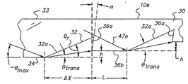
도 46A에서, 본 발명의 제5실시형태의 광학장치(10e)가 그 상부로부터 광선이 방출되는 구조화된 배면을 갖는 것으로 도시되어 있다. 광학장치(10e)는 장치의 저면(34)을 따라 경사구조부(32)와 하강구조부(36)가 상호 교대로 배열되는 광학물질의 동체(30)를 갖는다. 경사구조부(32)와 하강구조부(36)는 도 48에서 가장 잘 보인 바와 같이 장치의 상부면(33)에 실질적으로 평행한 장치의 축선(37)을 따라 연장되어 있다. 각 경사구조부(32)는 축선(37)에 대하여 예각을 이루는 상승면(32a)을 갖는다. 각 하강구조부는 축선(37)의 법선(37a)에 대하여 예각을 이루는 하강면과, 상부면에 실질적으로 평행한 면(36b)을 갖는다. 장치의 동체는 경사구조부(32)가 하강구조부(36)와 교대로 배치되고 단부(38)로부터 단부(39)로 장치를 따라 연장되면서 두께가 점진적으로 감소한다. 이후 이론적인 설명에 의하여 알 수 있는 바와 같이, 단부(38)로부터 입사될 때 광선은 장치의 상부면으로부터 방출되도록 경사구조부의 하나로부터 반사에 의하여 분배되거나 또는 인접한 하나의 하강구조부를 통하여 경사구조부의 하나를 통하여 동체측으로 전달될 때까지 동체(30)내에서 전반사된다.In Fig. 46A, the
설명을 위하여, 도 46B의 두 평면(41a)(41b)을 갖는 일반적인 광학소자(41)를 고려키로 한다. 광선이 단부(41c)에서 입사되고, 광선이 축선(40)에 대하여 이후 정의되는 각공간(angular space)으로 방출되며 다음 식으로 정의되는 광학소자(41)의 광학물질의 개구수(NA)에 의하여 특징지어진다.For the sake of explanation, consider a general
(52) NA = nsinθ max (52) NA = n sin θ max
여기에서 n 은 광선이 전파하는 주위 매질의 굴절률이고, θ max 는 임의의 축선, 이 경우에 있어서는 축선(40)에 대한 광선의 최대각도이다. 광선은 광원으로부터 입사되고, 만약 각도 θ max 가 충분히 작은 경우 광선은 광학장치 물질의 임계각도를 초과하지 않을 것이며 광선이 그 전파각도를 변경시키는 구조에 부딪치고 도광체로부터 방출될 때까지 전반사를 통하여 광학장치내에 갇혀있게 될 것이다. 광원으로부터의 광선(화살표 42로 보임)은 표면법선과 축선(40)에 대하여 공기중에서 각도 θ' 에서 광학소자(40)의 입구면(41c)에 부딪친다. 광선은 스넬의 법칙, nsinθ = sinθ' 에 따라 면(41c)에서 굴절되고 각도 θ 에서 광학소자(14)내에 전파된다. 결국 광선은 부분법선에 대하여 각도 β 로 상부면(41a)에 부딪친다. 만약 β 가 다음으로 정의되는 임계각도 보다 크면, 광선은 전반사(TIR)하며 표면을 통하여 전달되는 광선은 없다.Where n is the index of refraction of the surrounding medium through which the light beam propagates, and θ max is the maximum angle of light with respect to an axis, in this
(53) 
이는 도광체의 기본원리이다. TIR에 대한 θ 및 θ' 의 조건은 다음과 같다.This is the basic principle of the light guide. The conditions of θ and θ ′ for TIR are as follows.
(54) 

여기에서 n 이 ![]()
![]()
도 46A의 광학장치(10e)에서, 경사구조부(32)는 광선의 전파각도를 변경시켜 광선이 전면(33)으로부터 한정된 각공간으로 방출될 수 있도록 한다. 도 47은 광원(44)으로부터의 광선이 단부(38)로부터 광학장치(10e)로 입사되고 상부면(33)으로부터 광선(화살표 46)이 방출되는 광학장치(10e)의 예를 보인 것이다. 배면(34)을 따라 형성된 경사구조부(32)는 광선이 상부면(33)으로부터 방출될 수 있도록 광선이 광학장치(10e)의 내부로 다시 향한다. 비록 장치(10e)가 평면상 기판의 형태인 것으로 도시되어 있으나, 장치는 광학장치(10b-e)에 대하여 이미 언급된 것과 유사하게 만곡될 수 있다.In the
도 48은 도 46A의 구조화된 배면(34)을 보다 상세히 보이기 위한 부분단면도이다. 이미 언급된 바와 같이, 경사구조부(32)와 이에 따르는 하가우조부(36)가 반복되는 구조로 구성된다. 하강구조부(36)는 각주구조 또는 구조화된 면을 보이는 하강면(또는 하강단턱의 경사)(36a)과 평면(36b)을 갖는다. 경사구조부와 하강구조부의 반복구성은 광학장치(10e)의 크기와 광선이 방출되는 영역의 크기에 의하여 결정된다.FIG. 48 is a partial cross-sectional view for showing the structured back 34 of FIG. 46A in more detail. As already mentioned, the
도 48에서 보인 각도에 있어서, 먼저 단일상승면(32a)에 부딪치는 광선(47a)을 고려한다. 광선은 축선(37)에 대하여 각도 θ 로 전파된다. 도면에서 모든 각도는 θ 를 제외하고는 양의 각도이다. 광선은 상승면 법선에 대하여 각도 β 로 상승면(32a)에 부딪친다. 만약 β 가 임계각 보다 크면 광선은 전반사(TIR)되고 장치 의 상부면(33)을 향하여 상측으로 반사된다. 광선은 상부면(33)으로부터 각도 θ out 로 방출된다. 이들 각도와 상승면각도 θ r 사이의 관계는 다음과 같다.At the angle shown in FIG. 48, first consider the
β = 90°- θ r + θ β = 90 ° -θ r + θ
(55) θ' out = β - θ r = 90°- 2θ r + θ (55) θ ' out = β - θ r = 90 ° -2 θ r + θ
sin(θ out )=nsin(θ' out )=nsin(90°- 2θ r + θ)sin ( θ out ) = nsin ( θ ' out ) = nsin (90 ° -2 θ r + θ )
θ out 에 대한 양의 값은 표면법선에 대한 시계방향 각도를 나타낸다.Positive values for θ out represent the clockwise angle to the surface normal.
예를 들어, 광학장치(10e)의 광학물질이 굴절률 n=1.5 를 가지고 광원이 공기중에서의 개구수가 0.5 또는 30°를 갖는 것으로 가정한다. 장치에서 최대확산각도는 장치의 축선에 대하여 θ max = 19.47°가 될 것이다. 등식(55)을 좌표화함으로서 상승면각도의 함수로서 출력각도의 범위는 특정 θ 값, 즉 θ max , 0, 및 -θ max 에 대하여 결정될 수 있다. 도 49에서, 좌표는 이러한 예의 결과를 보인 것이다. 어느 주어진 상승면각도에서, 출력각도의 범위는 θ = θ max 및 -θ max 에 대하여 커브 사이의 수직간격에 의하여 결정된다. 예를 들어, 상승면각도가 40°인 경우, 출력각도는 수직점선으로 보인 바와 같이 -θ max 에 대하여 -14.3°로부터 θ max 에 대하여 47.6°까지의 범위를 갖는다. 굴절률의 증가는 이들 θ 커브가 보다 수직에 가깝도록 하고 이들이 서로 근접하게 하며 출력각도범위를 증가시킨다. 도 49에서, 예를 들어, 40°의 상승면각도는 -14 ~ 48도의 출력각도를 제공한다.For example, assume that the optical material of the
만약 상승면각도가 45°이면 θ = 0 의 광선은 직상부로 반사되고 표면에 수직인 출력면으로부터 방출되며 반사광선의 다른 출력각도는 0°를 중심으로 하여 대칭이고 입사광선과 동일한 NA로 방출된다.If the elevation angle is 45 °, the ray of θ = 0 is reflected upstream and emitted from the output surface perpendicular to the surface, and the other output angles of the reflected light are symmetric about 0 ° and emitted with the same NA as the incident light. .
만약 경사각도가 얕게 선택되어 출력각도 θ' out 가 상부면에서 임계각도 보다 크면, θ = θ max 커브에서 시작하여 광선의 일부가 상부면에서 전반사(TIR)되고 θ max 보다 큰 각도에서 광학장치의 하측으로 연속하여 전파되며, 이로써 광학장치내에서 광선의 개구수가 증가한다. 이는 광학장치의 배면측으로 상당한 손실이 일어나므로 바람직한 상황은 아니다. 도 49의 예에서, 최소상승면각도는 33.8°이고, 커브 θ = θ max 에서 출력각도가 90°인 지점이다. 따라서, 상승면각도는 이러한 상승면으로부터 반사되는 모든 광선이 전면으로 출사될 수 있도록 충분히 크게 선택되는 것이 바람직하다.If the inclination angle is selected to be shallow, the output angle θ ' out Is at the top surface the critical angle even greater than, θ = starting from θ max curve is propagated to a part of the light beam is totally reflected (TIR) at the top surface continuous to the lower side of the optical device at an angle greater than θ max, whereby in the optical device The numerical aperture of the light beams increases. This is not a desirable situation since significant losses occur on the back side of the optics. In the example of FIG. 49, the minimum rising plane angle is 33.8 °, and the point at which the output angle is 90 ° in the curve θ = θ max . Therefore, the elevation angle is preferably selected sufficiently large so that all the light rays reflected from the elevation surface can be emitted to the front side.
대부분의 경우 모든 광선이 상승면에 부딪칠 때 전반사(TIR)되지는 않을 것이다. 만약 도 48에서 β 가 등식(53)에서 주어진 임계각도 보다 작은 경우, 광선은 반사광선과 전달광선으로 분할된다. 반사광선은 상기 언급된 성향을 가지며 상부면으로부터 방출된다. 전달광선은 상승면(32a)으로부터 굴절되고 배면(34)으로부터 연속하여 전파된다. 상승면각도와 광선각도 모두는 이러한 조건이 나타나는 때를 결정하며 도 49의 예에서 점선의 커브 아래의 영역으로 보이고 있다. 이는 배면(34)이 대칭인 경우 각도에 관계없이 모든 광선이 출력면(33)을 향하여 반사될 것이다. 배면이 대칭이 되도록 하는 것이 모든 경우에 적합치 않으나, 특히 전달광 선이 대부분의 에너지를 이송하므로 이러한 광선을 포착하고 이를 출력면(33)으로 향하도록 설계기준을 고려하는 것이 유리하다.In most cases it will not be totally reflected (TIR) when all rays hit the rising surface. If β in FIG. 48 is smaller than the critical angle given in equation 53, the light beam is divided into reflected light and transmitted light. The reflected light has the aforementioned propensity and is emitted from the top surface. The transmitted light is refracted from the rising
상승면(32a)을 통하여 전달되는 광선에 대한 극한조건이 θ = -θ max 에서 광선이 상승면의 기부에 부딪칠 때 나타난다. 이는 도 50에 도시되어 있다. 굴절광선(47b)은 하강구조부(32)의 각주면(36a)을 차단하기 위하여 축선(37)에 대하여 각도 θ trans 에서 방출된다. 광선이 하강면(36a)에 부딪치는 높이 h 와 위치 Δx 는 장치의 점진적인 두께감소가 이루어지도록 하는 광학장치(10e)의 경사율을 결정한다. 이들 파라메타는 다음 식에 의하여 설명된다.The extreme conditions for the light beam passing through the rising
(56) 
만약 θ trans 가 극한 광선각도 θ = -θ max 에 대하여 양의 값이면, 테이퍼링(tapering) 높이 h 는 양의 값이고 광학장치(10e)의 두께는 광학장치의 길이를 따라 제1 경사구조부(2)와 하강구조부(36)를 간단히 이중으로 하여 방출영역의 길이를 따라서 감소될 수 있다. 만약 θ trans 가 음의 값이면, 하강면(36a)의 프리즘구조는 강선을 포착하기 위하여 배면의 평면을 지나 연장되어야 한다. 테이퍼링은 제2의 연속한 경사구조부(32)의 길이를 증가시켜 이루어질 수 있다. 이러한 예가 도 58에 관련하여 이후 상세히 설명될 것이다. 도 50으로부터 어느 주어진 각도 θ 에서 상승면 입사각도 β 는 다음과 같이 주어진다.If θ trans is positive for the extreme light angle θ = -θ max , the tapering height h is positive and the thickness of the
(57) β = 90°- θ r + θ (57) β = 90 ° -θ r + θ
전달각도 θ trans 는 다음과 같다.The transmission angle θ trans is
(58) θ trans = β' - (β - θ)(58) θ trans = β ' -( β - θ )
여기에서 β' 는 스넬의 법칙에 의하여 β 에 관련된다: sinβ' = nsinβ. 이와 같이 굴절광선과 상승면 및 입사광선각도 사이의 관계는 다음과 같다.Where β ' is related to β by Snell's law: sin β' = n sin β . As described above, the relationship between the refraction ray, the rising plane and the incident ray angle is as follows.
(59) θ trans = arcsin[ nsin(90°- θ r + θ )]-90°+ θ r (59) θ trans = arcsin [nsin (90 ° -θ r + θ )]-90 ° + θ r
이 식은 θ 의 동일한 3개의 값, 즉, θ max , 0 및 -θ max 에 관하여 도 51에 이전의 예로써 좌표에 도시되었다. θ trans 의 최대값은 도면에서 점선으로 보인 바와 같이 상승면(32a)의 임계각도에서 나타나는 상승면각도 θ r 이다. 28.7°이하인 상승면각도에 대한 이러한 예에서, 모든 광선은 상승면에서 전반사(TIR)가 일어날 것이나, 도 49에서 보인 바와 같이 이러한 상승면각도는 상부면에서 이들 반사광선의 일부에 대하여 전반사(TIR)가 이루어질 것인 바, 이는 광학장치(10e)내에서 광선의 NA 를 유지하기 위해 방지하고자 하는 상황이다. 절충이 이루어지고 일부 광선이 상승면(32a)을 통과할 수 있도록 허용되어야 한다. 상승면각도는 상승면(32a)으로부터 전반사(TIR) 광선에 적당한 반사각도를 부여하도록 선택되어 이들 광선이 상부면(33)으로 출사되는 반면에 다른 광선은 전달각도로 굴절하여 이들이 하강면(36a)의 각주구조부에 의하여 포착되고 광학장치(10e)측으로 재순환되어야 한다.This equation is shown in the coordinates as a previous example in FIG. 51 with respect to the same three values of θ , namely θ max , 0 and −θ max . The maximum value of θ trans is the rising face angle θ r that appears at the critical angle of the rising
다시 경사구조부(32)에 인접한 하강(하향경사)구조부(36)의 각주구조로 돌아가서, 이 목적은 상승면(32a)을 통과하는 광선을 포착하고 이들을 ±θ amx 사이의 각 도에서 광학장치(10e)측으로 후퇴시키기 위한 것이다. 이는 광선이 부딪치는 광선의 각공간과 포착되어 후퇴된 광선을 전파하기 위하여 요구된 각공간에 따라서 양의 방향 또는 음의 방향으로 경사진 면일 수 있다. 이들 광선이 광학장치로 ㅈ입사되는 각도 θ ref 는 하강면(36a)의 각주구조를 보다 상세히 보인 도 52의 도움을 통하여 결정된다. 하강면(32a)의 입구면은 수직선에 대하여 각도 α 를 이루고, 전달광선(47c)은 표면법선에 대하여 각도 β 를 이룬다. 이러한 광선은 장치축선(37)에 대하여 각도 θ ref 를 이루어 광학장치(10e)에 재입사될 때 법선에 대하여 각도 β' 로 굴절한다. 이들 각도 사이의 관계는 다음과 같다.Returning to the footnote structure of the descending (downhill)
sin(β)=nsin(β')sin ( β ) = nsin ( β ' )
(60) β = α + θ trans (60) β = α + θ trans
β = α + θ ref β = α + θ ref
도면에서 모든 각도는 양의 방향을 갖는 것으로 도시되어 있다. α 과 θ trans 의 항에서 θ ref 를 풀면 다음과 같다.All angles in the figures are shown to have a positive direction. Solving θ ref in terms of α and θ trans is
(61) 
도 53에서, 이 등식의 결과는 α 가 제로, 제로 보다 크거나, 제로 보다 작은 경우와, n=1.5 에 대하여 좌표로 작성되었다.In Fig. 53, the result of this equation is plotted as the coordinates for the case where α is zero, greater than zero, or smaller than zero and n = 1.5.
상승면의 상승거리 L, 상승면길이 Δx, 그리고 상승면(32a)의 수는 상부 면(33)으로부터의 방출영역의 길이를 결정한다. 도 54A-C에서, L에 대한 3개의 가능성이 제1상승면(32a)에 미치지 못한 하나의 극단적인 예의 광선 θ = -θ max 이 도광체의 다음 표면에 부딪치는 위치에 기초하여 도시되어 있다. 도 54A에서, 이러한 극단적인 예의 광선(47d)은 상승면 기부로부터 상부위치에서 제2상승면(32a)에 부딪친다. 연속하여 전달되는 전달광선은 제1상승면(32a) 보다 높은 위치 h2 에서 다음의 각주형 하강면(36a)에 부딪칠 것이다. 또한 , 만약 h 가 동일하게 유지되는 경우, 길이 Δx2 는 짧아진다. 이러한 경우 L 은 제로가 되고, 각 상승면(32a)은 앞의 각주형 하강면(36a)의 기부에서 시작한다.The rising distance L of the rising surface, the rising surface length Δx, and the number of the rising
도 54B에서, 제1상승면(32a)에 미치지 못하는 극단적인 예의 광선(47e)이 제2상승면(32a)에 부딪치는 특별한 경우가 도시되어 있다. 광학장치에서 광선의 NA, 상승면각도, 프리즘각도, 상승면길이 Δx 및 테이퍼 높이 h 는 모두 L 의 값을 결정한다.In FIG. 54B, a special case is shown in which an extreme
도 54C는 L 이 도 54B의 경우 보다 큰 값을 갖는 경우를 보인 것이다. 이 경우에서 극단적인 예로 보인 일부의 광선(47f)은 축선(37)에 평행한 평면(36b)에 부딪친다. 이들 광선(47f)과 이 평면(36b)에 부딪치는 모든 광선은 전반사(TIR)되고 광학장치의 하측으로 전파된다. 이와 같이 함으로서 상부면(33)으로부터 방출영역의 길이가 연장될 수 있다. 이는 상승면(32a)의 각 점이 광선의 전체 내부 NA에 의하여 조명되는 잇점을 갖는다. 만약 길이 L 이 광학장치(10e)의 다른 파라메타에 대하여 커진다면, 상부면(33)에서 방출되는 광선의 공간분포는 균일하지 않고 밴딩 효과(banding effects)를 보일 것이다. 이는 사용자가 출력면(33)을 직접 바라보게 되는 디스플레이와 같은 경우 문제가 될 것이다. 그러나, 범용의 조명인 경우, 문제가 되지 않을 것이며 방출영역의 길이를 연장하기 위하여 바람직할 수 있다.54C shows the case where L has a larger value than that of FIG. 54B. Some
전달광선 θ trans 이 음의 값인 일부의 경우에 있어서, 광학장치를 테이퍼형으로 구성할 수 있는 가능성은 도 54A-C에서 보인 광학장치(10e)로 제한될 것이다.In some cases where the transmitted light θ trans is a negative value, the possibility of tapering the optics will be limited to the
도 55A에서, 이는 본 발명의 제6실시형태의 광학장치(10f)를 보인 것으로, 교대로 하강구조부가 형성된 것을 제외하고는 장치(10e)와 유사한 바, 이들 장치(10e)(10f)에서는 동일한 부분에 대하여 동일한 부호를 붙였다. 장치(10f)에서, 각 하강구조부(36)는 하강면(36a)과 평면(36b) 사이에 상승면(36c)을 갖는다. 상승면(36c)은 축선(37)에 대하여 각도 γ 를 이룬다. 이 상승면(36c)은 전달광선의 일부를 그 광선의 본래 NA 를 유지한 상태에서 다른 방향으로 향하도록 하고 상승면(32a)의 최고점에 미치지 못하는 극단적인 예의 제1 광선(47g)을 차단하는 지점에 평면(36b)이 놓일 수 있도록 하여 광학장치(10f)의 두께를 줄이는 수단을 제공한다. 광학장치(10f)의 배면측 본래의 평면에 대항 이러한 평면(36b)의 높이는 변화될 수 있다. 이는 광학장치(10f)의 길이를 따라 상승면(32a)과 하강면(36a) 사이의 길이 L 을 변화시킬 수 있는 매우 큰 다양성을 주는 것이다.In Fig. 55A, this shows the
도 55B에서, 극단의 광선(47h)가 θ = -θ max 에서 추적된다. 이는 각도 θ ref 에서 광학장치에 재입사되는 지점에서 광선이 각주형 하강면(36a)에 부딪칠 때까지 각도 θ trans 에서 제1상승면(32a)을 통과한다. 광선은 상승면(36c)으로 전파되고 여 기에서 각도 θ ref 로 전반사되어 광학장치의 하측으로 연속하여 전파된다. 상승면(36c)의 굴절각도 θ ref 와 상승각도 γ에 의하여 반사각도가 다음과 같이 주어진다.In FIG. 55B, the
(63) θ refl = 2γ - θ ref (63) θ refl = 2γ- θ ref
이 각도는 광학장치(16f)에서 광선의 최대각도, 즉 θ max 보다 작은 것이 요구된다. γ 가 고정되었을 때 상승면(36b)의 테이퍼 높이 h 와 길이 δ 의 최대값은 도시된 바와 같이 극단의 광선을 상승면(36c)으로 차단함으로서 결정된다.This angle is the maximum angle of the light beam in the optics 16f, i.e. θ max Smaller is required. When γ is fixed, the maximum value of the taper height h and the length δ of the rising
상승면(36c)에 반사되는 모든 광선이 광학장치(10f)의 상부면(33)에 부딪치기 전에 다음의 상승면(32a)의 표면에 부딪치는 경우 θ refl 가 θ max 보다 작아야 하는 조건은 완화될 수 있다. 상부면(33)에서, 이들은 임계각도 보다 작아서 이들이 출사될 수 있으나 전반사가 이루어지지 않는다. Θ refl when all light rays reflected by the rising
도 46A의 광학장치(10e)의 한 예가 설명될 것이며, 경사구조부(32)와 하강구조부(36)는 도 54A에 도시되어 있고, 여기에서 각주형 하강면(36a)은 상승면(32a)을 통하여 전달된 광선을 포착할 수 있을 정도로 충분히 크며, 평면(36b)이 각 쌍의 상승부분 사이에 존재한다. 이러한 예에서, 광학장치에 입사되는 광선은 공기중의 개구수가 0.5 이고 굴절률이 1.5 인 물질로 되어 있다. 광학장치내에서, 광선의 각도는 광학장치의 길이에 대하여 -19.74°~ +19.74°의 범위이다. 상부면(33)으로부터의 출력은 도 47 및 도 48에서 보인 바와 같이 이러한 예에서는 표면법선에 대 하여 대칭인 것이 바람직하다. 요구된 출력광선분포는 대칭이므로 45°의 상승면각도가 선택되어 상부면(33)으로부터 출사되는 광선의 출력각도범위가 ±30°가 되도록 한다. 이러한 상승면각도는 도 51의 그래프에서 보인 바와 같이 광선이 음의 각도, 즉, 축선(37) 아래의 각도에서 상승면(32a)을 통하여 전달될 수 있도록 한다.An example of the
각주형 하강면(36a)에서 광선은 포착되어 광학장치로 다시 보내지는 것에 요구된다. 도 56A에서, 이러한 예에 따른 광학장치(10c)가 도시되어 있고, 도 56B는 3개의 제1 경사구조부(32)와 이에교대로 배치되는 하강구조부(36)의 상세한 단면을 보인 것이다. 구조부(32)(36)에 의한 광선의 효과는 예시된 광선에 의하여 보이고 있다. 제1 상승면(32a)에서 두 전달광선(48a)(48b)가 고려된다. 하나의 광선(48a)은 극단의 광선 θ = -θ max 으로부터 시작하고 다은 광선(48b)은 임계각도 바로 아래에서 상승면(32a)에 부딪쳐 상승면각도 θ r 에서 전달광선을 발생한다. 이들은 각주형 하강면(36a)을 위한 각도범위를 결정할 것이다. 극단의 광선은 -4.7°의 각도로 45°상승면을 통하여 전달된다. 이러한 광선(48b)을 포착하기 위하여, 각주형 하강면(36a0은 배면(34a)을 제공하도록 연장되고 이러한 배면은 본래의 배면(34)의 레벨 아래에 놓인다. α=-9.3°의 프리즘각도는 이러한 광선(38b)을 광학장치내에서 θ = 0°으로 후퇴시킨다. 그러나, 제2 광선(48a)이 고려되어야 한다. θ trans = θ r 과 θ ref = θ max 일 때 각주형 하강면 각도 α에 대한 등식(61)의 해석으로 각도 α = 16.3°를 얻는다.이러한 각도에서, 본래 θ = -θ max 광선(48b)은 광선의 본래 NA내에서 -8.6°의 각도로 프리즘구조에 재입사된다. 이러한 에에서, 상승면각도 θ r 와 각주형 하강면 각도 α는 광학장치의 전길이에 걸쳐 일정하다. 광학장치(10e)의 다른 예에서, 상승면과 프리즘하강면의 각도는 특정의 조명을 위하여 요구된 바에 따라 변화될 수 있다.Light is captured at the
다음 상승면(32a)에 대한 거리 L은 여러 요인으로 결정된다. 테이퍼 구조를 얻기 위하여 다음 하강구조부(36)의 기부는 배면(34) 보다 높아야 한다. 이는 최하측 극단의 광선(48c)이 도 56B에서 변수 h 로 보인 바와 같이 상승면(32a)의 기부의 상부 위치에서 제2상승부(32a)에 부딪치는 것을 요구한다. 거리 L 이 작으면 작을 수록 충돌위치는 높아질 것이다. 만약 연속하는 제2의 상승면(32a)의 높이 H 가 높이 h 와 동일한 경우 모든 상승면과 간격은 동일할 것이다. 만약 H 가 h 보다 크면 거리 L 은 광학장치(10e)의 길이를 따라서 증가할 것이다. 상승면(32a)은 도 58에서 보인 광학장치(10e)의 예에서 보인 바와 같이 크기가 증가하오 사이의 간격이 커질 것이다.The distance L to the next rising
도 56의 예에서 출력광선분포가 도 57에 도시되어 있으며 이는 H = h 인 경우이고 상승면(32a) 사이의 간격이 도광체의 전길이를 따라 균일하다. 도 57의 그래프는 출력상부면(33)에 인접한 평면에서 광학장치의 축선을 따른 상대광선분포를 보이고 있다. 위치 x = 0 은 배면 구조부(32)(36)의 시작을 나타낸다. 광선분포는 이 위치에서 최대이고 광학장치의 길이를 따라 하측으로 갈수록 점진적으로 감소한다. 광선분포의 균일성은 장치의 하측으로 이동할 때 상승면의 거리 L 를 감소시켜 단위길이당 상승면의 수를 증가시킴으로서 보다 많은 광선의 추출이 이루어지도록 하거나, 또는 H 를 h 보다 높게 함으로서 도 58에서 보인 바와 같이 도광체의 하측으로 이동할 때 상승면의 표면적을 증가시킴으로서 개선될 수 있다.In the example of FIG. 56, the output light distribution is shown in FIG. 57, where H = h and the spacing between the rising
도 55A - 도 55B 의 부가적인 상승면(36c)을 이용하는 광학장치(10f)의 예가 상세히 설명될 것이다. 도 59A는 이러한 예에 따른 광학장치(10f)를 보이고 있고, 도 59B는 3개의 제1 경사구조부(32)와 이들 사이에 교대로 배치되는 하강구조부(36)의 상세한 단면을 보인 것이다. 모든 경사구조부와 하강구조부는 동일하고 이들 사이의 간격이 일정하다. 이러한 예의 출력광선분포가 도 60에 도시되어 있다. 그래프는 출력상부면(33)상에서 광학장치의 길이를 따른 광선분포를 보이고 있다. 이 예는 앞서의 예 보다 더 나은 균일성을 보이며 상승면(32a)의 거리 L 의 변화에 의하여 개선될 수 있다. 도 61의 그래프는 거리 L 이 선형으로 제1상승면(32a)에서의 최대값으로부터 최종 상승면(32a)의 제로값까지감소되는 광선분포의 결과를 보이고 있다. 이러한 예의 다른 파라메타, 즉 상승면각도, 상승면 길이 및 2차 상승면각도는 동일하다. 상승면(32a) 사이에서 거리의 이러한 감소는 광선분포균일성을 현저히 개선한다. 도 34A, 도 34B, 도 35A, 도 35B, 도 57 및 도 60과 함께, 도 61에서 보인 출력분포가 미국 아리조나 투싼에 소재하는 Breault Research Inc 에서 판매하고 있는 ASAP 와 같은 광학모델링 컴퓨터 소프트웨어를 이용하여 시뮬레이션되었다.An example of an
대부분의 경우, 통상적으로는 특정 광원으로부터 유용한 범위를 벗어나는 범위로 단일의 상승면각도를 이용하여 출력광선의 각도확산을 증가시키는 것이 바람 직하다. 도 49는 주어진 광원의 개구수와 도광체 굴절률에서 출력각도의 범위가 등식(55)의 식에 의하여 주어진 상승면각도에 의하여 제한됨을 보이고 있다. 하나의 상승면의 각도를 인접한 것에 대하여 변화시키거나 또는 각 상승면을 분할하여 각 분할부분이 약간씩 다른 각도를 갖도록 함으로서 다중의 상승면각도를 결합하여 출력각도범위를 증가시킬 수 있다.In most cases, it is usually desirable to increase the angular spread of the output beam using a single elevation angle out of a useful range from a particular light source. FIG. 49 shows that the range of the output angle at the numerical aperture and the light guide refractive index of a given light source is limited by the elevation angle given by the equation (55). The output angle range can be increased by combining multiple rising surface angles by changing the angle of one rising surface relative to the adjacent one or dividing each rising surface so that each divided portion has a slightly different angle.
각 상승면(32a)의 이러한 분할이 도 62에 도시되어 잇으며, 여기에서, 상승면(32a)은 점진적으로 가파른 불연속각도를 갖는 3개의 분할부분(49a)(49b)(49c)으로 나누어진다. 상승면각도, 출력각도, 프리즘면각도 및 2차상승면각도 사이의 관계를 설정하는 설계기준이 각 상승면의 각 분할부분에도 적용된다. 상승면의 제1분할부분(49a)은 가장 작은 각도를 가짐으로서 이러한 분할부분으로부터 방출되는 전달광선은 최대 양의 경사각도를 가질 것이며 각주형 하강면(36a)에 의하여 용이하게 포착될 것이다. 따라서, 이러한 면(36a)은 도 58의 예의 제1하강구조부(36)의 경우와 같이 배면측 평면 아래로 연장되어서는 안 된다.This division of each
출력각도를 넓히는 것은 도 63에서 보인 바와 같이 상승면 경사의 연속변화에 의하여 이루어질 수 있다. 불연속 경사면을 갖는 분할형 상승면을 대신하여, 상승면(32a)은 연속커브(49d)를 이룰 것이며, 경사범위는 아웃 커플링된 광선의 출력각도의 요구된 범위에 의하여 결정된다.Widening the output angle may be achieved by a continuous change of slope of the rising surface as shown in FIG. In place of the split raised surface with discontinuous inclined surfaces, the raised
선택적으로, 광학장치(10e 또는 10f)의 저면(34)(구조부 32와 36을 포함한다)은 유전체 또는 금속과 같은 반사물질의 층 또는 코팅을 가질 수 있다. 예를 들어, 반사물질은 거울 또는 반도체의 제조에 이용되는 것과 같은 통상적인 금속화공 정을 이용하여 도층될 수 있다. 이러한 반사물질의 이용으로 저면(34)을 따른 전반사는 모든 광선이 반사되므로 더 이상 설계상 제약을 보이는 것은 아니며 하강구조부의 각도는 광학장치의 설계에 있어서 한계가 아니다.Optionally, the bottom face 34 (including
도 64A-C는 본 발명의 제7실시형태에 따른 광학장치(10g)의 예를 보인 것으로, 이는 광학장치(10b-d)의 상면측 구조부(50)와, 광학장치(10e-f)의 저면측 구조부(51)를 갖는 광학물질의 단일동체를 갖는다. 장치(10g)의 동체(52)는 상부면(53a)을 따라 상면측 구조부(50)를 갖는 제1동체부(52a)와, 저면(53b)을 따라 저면측 구조부(51)를 갖는 제2동체부(52b)를 갖는다. 단부(54)를 따라 입사될 때 제1동체부(52a)의 구조부(50)에 의하여 분배되지 않는 광선은 제2동체부(52b)로 보내어진 다음 구조부(51)에 의하여 분배된다. 제1동체부(52a)로부터 분배된 광선(54)과 제2동체부(52b)로부터 분배된 광선은 장치(10g)의 상부면(53a)으로부터 이루어지는 조합된 조명(56)을 제공한다. 비록 단 2개의 동체부(52a)(52b)가 도시되었으나, 장치(10g)는 장치의 길이를 따라광선의 입사가 이루어질 수 있도록 입력단부로부터 다수의 연속부분을 가질 수 있으며, 여기에서 적어도 하나의 상기 부분은 다수의 구조부(51)를 가지고, 적어도 하나의 다른 부분은 다수의 구조부(52)를 갖는다. 앞의 실시형태인 광학장치(10b-10f)의경우와 같이, 광학장치(10g)는 장치의 광학물질의 굴절률에 따라서 사전에 한정된 광선분포를 따라 제공될 수 있으며, 이러한 파라메타는 장치(10b-10f)에 대한 이러한 광선분포의 선택을 위하여 이미 언급되었다.64A-C show an example of the
광학장치(10b-e)를 설명하는 도면은 이들의 각 상부면(14b-e)을 따라 일정한 주기를 갖는 반복주기패턴을 갖는 구조를 보이고 있다. 이는 이들 장치로부터 균일한 광선분포를 얻는데 바람직한 것이다. 그러나, 일부의 경우에 있어서, 불균일한 분포가 바람직할 때가 있는데, 이 경우 구조부의 주기 및/또는 높이가 모든 장치 또는 일부의 장치에서 상이할 수 있다. 예를 들어, 도 65는 장치의 여러 영역으로부터 광선분포를 제어하고 변조하기 위하여 경사구조부(22)의 높이와, 평면(24)을 갖는 경사구조부(22)의 주기가 상부면(14d)을 따라서 변화하는 도 25의 광학장치(10d)를 보이고 있다. 비록 이러한 예가 입력단부(16d)로부터 장치의 길이를 따라 비례하여 증가하는 주기와 높이를 보이고 있으나, 주기 및/또는 높이의 불균일한 변화가 특별한 경우에 요구되는 바와 같이 장치로부터 출사되는 광선의 세기와 분포를 제어하기 위하여 유사하게 이용될 수 있다. 또한, 비록 이러한 예가 광학장치(10d)를 이용하는 것으로 설명되고 있으나, 다른 광학장치(10b,c,e)도 이들의 각 전면구조에서 주기와 높이가 변화될 수 있다. 더욱이, 비록 도 58의 광학장치(10e)의 예가 단부(38)로부터 단부(39)까지 입력단부(16d)로부터 비례하여 증가하는 주기와 높이를 갖는 구조부(32)(36)를 보이고 있으나, 광학장치(10f) 역시 주기와 높이네서 유사하게 증가하는 구조부(32)(36)를 가질 수 있거나, 또는 광학장치(10e 또는 10f)가 특별한 경우에 요구될 때 장치로부터 출사되는 광선의 세기와 분포를 제어하기 위하여 주기 및/또는 높이를 변화시키는 하나 이상의 구조부(32)(36)를 가질 수 있다.The figure illustrating the
적용에 있어서, 광선은 광섬유케이블, 광섬유번들(fiber bundle), 발광다이오드(LED), 또는 다른 유사한 광원과 같은 다양한 광원의 하나로부터 광학장 치(10a-g)에 그 단부로부터 입사된다. 확장형 광원을 갖는 루미네어(58)가 예를 들어 도 66에 도시되어 있다. 도 66에서, 루미네어(58)는 광학장치(62)와 이러한 광학장치(62)의 폭을 따라 조명이 이루어지도록 하는 확장형 광원(60)을 갖는 하우징(59)을 가지며, 이러한 조명은 장치(62)를 따라 방출영역(63)(점선으로 보임)으로부터의 출력을 위하여 분배된다. 예를 들어 확장형 광원(60)은 광학장치(62)의 입력면(62a)의 방향으로 광선을 분배하도록 차폐된 형광튜브를 나타낸다. 광학장치(62)는 방출영역이 광학장치의 상부면을 따라 형성된 광학장치(10b-g)의 하나 또는 이들의 조합일 수 있다.In applications, light rays are incident from their ends on
발광다이오드(LED) 광원(70)을 갖는 루미네어(64)가 예를 들어 도 67에 도시되어 있다. 도 67에서, 루미네어(64)는 광학장치(68)와 이러한 장치(68)를 따라서 방출영역(69)(점선으로 보임)으로부터의 출력을 위한 조명이 이루어지도록 하는 LED 광원(70)을 갖는 하우징(66)을 갖는다. 광학장치(68)는 테이퍼형 입력단부(68a)를 가지며, 이는 소형의 단일 LED 광원(70)으로부터의 조명이 광학장치의 넓은 폭을 걸쳐 균일하게 확산될 수 있도록 한다. 이는 디스플레이를 위한 조명과 같은 범용의 조명에 유용하다. 입력단부(68a)는 도 45의 입력단부(28c)와 유사하다. 광학장치(68)는 방출영역이 이러한 장치의 상부면을 따라 형성된 광학장치(10b-g)의 하나 또는 이들의 조합일 수 있다.A
광원 어레이를 갖는 루미네어(72)가 예를 들어 도 68에 도시되어 있다. 도 68에서, 루미네어(72)는 광학장치(76)와 이러한 장치(76)를 따라서 방출영역(77)(점선으로 보임)으로부터의 출력을 위한 조명이 이루어지도록 하는 LED 광원의 어레이(78)를 갖는 하우징(74)을 갖는다. 광학장치(76)는 그 입력면(76a)으로부터 장치의 길이를 따라 경사져 있어 점진적인 두께감소가 이러한 방향으로 개구수를 감소시킨다. LED 어레이(78)는 효율적인 건축 및 디스플레이 분야의 유색혼합형 백색광 조명이 이루어질 수 있도록 동일한 색깔, 또는 적색(R), 녹색(G), 청색(B)과 같은 다색형일 수 있다. 혼합형 RGB LED 광원이 백색광 LED 보다 효율적이다. 또한 어레이(78)는 1차 또는 2차원 LED 어레이, 또는 다중열의 LED 어레이일 수 있으며, 다중열인 경우 각 열은 요구된 유색발광효과를 제공하기 위하여 적색(R), 녹색(G) 또는 청색(B), 또는 이들의 조합과 같은 여러 컬러 채널(color channel)의 조명을 제공한다. 입력면(76a)으로부터 그 길이를 따라 두께가 테이퍼형으로 형성된 이러한 예의 루미네어(72)는 이러한 방향으로 협각의 조명을 제공할 수 있고, 이로써 루미네어는 전파방향이 수직투시방향과 정렬되는 LCD 디스플레이의 백라이트 유니트를 구성할 수 있어 감소된 개구수가 대부분의 다스플레이 장치에서 수직방향으로 요구된 감소된 투시각도와 정렬된다.
광섬유 광원을 갖는 루미네어(80)가 예를 들어 도 69에 도시되어 있다. 도 69에서, 루미네어(80)는 하우징(82)을 가지며 이 하우징은 광원(램프)(85)을 구성하는 광섬유 광원(84)의 단부로부터 광선이 전달되는 광학장치(83)와 입력단부(86a)와 하우징(82)측으로 연장된 출력단부(86b)를 갖는 광섬유(86)를 갖는다. 따라서 광원(85)으로부터의 광선은 외부의 원격지로부터 하우징(82)으로 보내어진다. 이러한 예의 루미네어(80)는 태양, 레이저 또는 단일 램프광원(84b)으로부터 원격한 광원의 조명에 유용하다. 단일의 원격광원이 범용의 조명을 위한 하나 이상 의 루미네어(80)에 광선을 제공한다. 광학장치(83)는 방출영역(81)(점선으로 보임)이 이러한 장치의 상부면을 따라 형성된 광학장치(10b-g)의 하나 또는 이들의 조합일 수 있다.A
도 66 - 도 69의 하우징(59)(66)(74)(82)과 이에 수용되어 있는 구성요소들은 요구된 조명이 이루어질 수 있도록 하는 크기와 형상을 갖는 것으로, 도면에 도시된 것에 한정되는 것은 아니다. 하우징(59)(66)(74)의 경우, 광원(60)(70)(78)은 각각 케이블 또는 코넥터(59a)(66a)(74a)를 통한 전기적인 연결을 통하여 전원이 인가된다. 이러한 전원은 하우징내에 내장되는 배터리일 수 있다. 또한, 이러한 루미네어(58)(64)(72)(80)은 하우징 없이 사용되거나 대형 하우징의 일부일 수 있으며 LCD 디스플레이와 같은 다른 전기적인 구성요소 또는 광학적인 구성요소와 조립될 수 있다. The
도 66 - 도 69에서 보인 바와 같이, 광원은 광학장치(10a-g)의 광선입력단부로부터 광선의 입사가 이루어질 수 있도록 하는데 사용될 수 있고, 이러한 광학장치와 같이 루미네어로 불리는 조명장치의 일부로서 광원이 결합될 수 있으며, 여기에서 광선은 광학장치의 전면 및 배면에 수직인 방향에서 시준되거나 시준됨이 없이 광학장치에 입사될 수 있다. 예를 들어 이러한 조명장치는 사전에 한정된 방향으로 광선을 전파하기 위한 루미네어, 하나 이상의 형광광원을 이용하는 형광조명장치, 솔리드 스테이트 LED 광원을 이용하는 LED 조명장치, 레이저광원으로부터의 광선을 이용하는 레이저조명장치, 백열광원을 이용하는 백열광조명장치, 채광창 또는 채광윈도우의 일부와 같은 태양광장치, 태양광원 과 솔리드 스테이트 LED 광원 조명장치, 또는 원격지로부터 다른 도광체 또는 광섬유를 통하여 광선이 분배되는 원격광원, 형광, 백열광 LED, 또는 태양광원과 같은 하이브리드 광원의 조명장치일 수 있다.As shown in FIGS. 66-69, the light source can be used to allow incidence of light rays from the light input end of the
예를 들어, 건축조명분야에서, 광학장치(10a-g)는 벽부착형 또는 천전부착형 조명을 위한 평면상 루미네어, 천정부착형 형광등기구의 대체용으로서 탁상용의 입체형 조명과 같은 사무실조명을 위한 루미네어의 일부일 수 있다. 다른 조명분야로서는 비상등과 같은 직접조명을 위한 조명장치, 극장, 미술관 또는 특별전시실과 같은 어두운 공공장소의 통로, 선반, 광선이 층계뒷판을 향하는 계단, 벽장조명을 위한 옷걸이봉 등의 조명장치일 수 있다.For example, in the field of architectural lighting, the
또한 광학장치(10a-g)는 액정디스플레이의 백라이트조명, 이러한 기술을 이용하는 백라이트 간판, 또는 도광기술을 이용하는 채널-레터(channel-letter) 간판용으로 이용될 수 있다.The
또한 광학장치(10a-g)는 의료, 치과 및 수의용 장치와 기구의 조명, 외과의용 손목착용 조명광원, 또는 의료종사자용 두부부착형 조명을 위하여 사용될 수 있다. 다른 분야로서는 광역동치료용 조사, 모발성장 및 피부관리와 같은 다른 형태의 광선요법을 위한 환자신체에 대한 조사, LED 광원으로부터의 정밀조명, 또는 컬러 믹싱이 이루어지도록 조사를 통한 서캐디안리듬(circadian rhythm)을 위한 정밀색온도조사를 포함한다.The
또한 광학장치(10a-g)는 운반수단조명분야(예를 들어, 배니티 라이트 및 돔 라이트와 같은 평판조명, 항공기용 간접조명, 항공기 및 승용차용 직접독서등, 항 공기의 비상구 직접조명), 개인조명분야(예를 들어, 광원과 광원장치를 모자챙에 결합한 조명, 두부부착형 광원, 작업자가 손목이나 머리에 착용할 수 있는 광원), 공구조명분야(예를 들어, 공구핸들에 광학장치와 광원을 결합시킨 수동공구, 헬멧과 장갑, 조명형 자, 레벨, 동력공구 핸들 및 보호물과 같은 안전기구에 도광체를 결합함으로서 개인사용을 위한 안전조명), 스포츠조명분야(예를 들어, 농구백보드와 같은 야구배트, 하키 스틱, 라크로스 스틱과, 테니스 라켓과 같은 조명형 스포츠장비, 또는 하키, 풋볼 및 축구와 같은 골대 및 그물의 구조적인 조명형 튜브), 주방조명분야(예를 들어, 바베큐 기구의 핸들에 도광체를 결합시킨 바베큐기구의 조명 또는 전기주방기구핸들의 조명)에 이용될 수 있다.In addition, the
이상의 설명으로부터, 본 발명은 조명광 도광용 광학장치와 이러한 장치를 이용하는 루미네어를 제공함을 알 수 있다. 이상의 본 발명에 따른 조명광 도광용 광학장치와 루미네어의 변경 및 수정은 전문가에게 의심없이 제안될 수 있다. 따라서, 이상의 내용은 설명을 위한 것으로 어떠한 제한을 두고자 하는 것은 아니다.From the above description, it can be seen that the present invention provides an optical device for guiding illumination light and a luminaire using such a device. Changes and modifications of the illumination light guide optical device and the luminaire according to the present invention can be proposed without doubt to the expert. Accordingly, the above description is for illustrative purposes only and is not intended to be limiting.
Claims (57)

Applications Claiming Priority (2)
| Application Number | Priority Date | Filing Date | Title |
|---|---|---|---|
| US11/351,699 | 2006-02-10 | ||
| US11/351,699 US7593615B2 (en) | 2006-02-10 | 2006-02-10 | Optical devices for guiding illumination |
Publications (1)
| Publication Number | Publication Date |
|---|---|
| KR20090015884A true KR20090015884A (en) | 2009-02-12 |
Family
ID=38368584
Family Applications (1)
| Application Number | Title | Priority Date | Filing Date |
|---|---|---|---|
| KR1020087021752A KR20090015884A (en) | 2006-02-10 | 2007-02-08 | Optical device for guiding illumination |
Country Status (8)
| Country | Link |
|---|---|
| US (3) | US7593615B2 (en) |
| EP (1) | EP2008132A4 (en) |
| JP (1) | JP2009526368A (en) |
| KR (1) | KR20090015884A (en) |
| CN (2) | CN101421557B (en) |
| AU (1) | AU2007215434A1 (en) |
| CA (1) | CA2641961A1 (en) |
| WO (1) | WO2007095049A2 (en) |
Families Citing this family (111)
| Publication number | Priority date | Publication date | Assignee | Title |
|---|---|---|---|---|
| US8409088B2 (en) | 2006-01-18 | 2013-04-02 | Invuity, Inc. | Retractor illumination system |
| US7593615B2 (en) * | 2006-02-10 | 2009-09-22 | Rpc Photonics, Inc. | Optical devices for guiding illumination |
| US7997781B2 (en) * | 2006-05-25 | 2011-08-16 | I2Ic Corporation | Energy efficient illumination for a light source in the form of a surface |
| JP4463246B2 (en) * | 2006-07-26 | 2010-05-19 | 株式会社フジクラ | Light guide for linear illumination device |
| GB2443849A (en) * | 2006-11-20 | 2008-05-21 | Sharp Kk | Backlight and display |
| US7551243B2 (en) * | 2006-11-21 | 2009-06-23 | Honeywell International Inc. | Lens for increased light distribution uniformity in an LCD backlight |
| US8088066B2 (en) | 2007-10-24 | 2012-01-03 | Invuity, Inc. | Blade insert illuminator |
| US7857719B2 (en) * | 2008-01-10 | 2010-12-28 | Easton Sports, Inc. | Ball bat with exposed region for revealing delamination |
| EP2297512B1 (en) | 2008-05-30 | 2019-01-02 | Philips Lighting Holding B.V. | Illumination device comprising a light guide |
| US8475010B2 (en) | 2008-05-30 | 2013-07-02 | Koninklijke Philips Electronics N.V. | Illumination device comprising a collimator |
| US8317693B2 (en) | 2008-08-13 | 2012-11-27 | Invuity, Inc. | Cyclo olefin polymer and copolymer medical devices |
| US9282878B2 (en) | 2008-08-13 | 2016-03-15 | Invuity, Inc. | Cyclo olefin polymer and copolymer medical devices |
| US11382711B2 (en) | 2008-08-13 | 2022-07-12 | Invuity, Inc. | Cyclo olefin polymer and copolymer medical devices |
| DE102008049407A1 (en) | 2008-09-29 | 2010-04-01 | Carl Zeiss Ag | Display device and display method |
| DE102008057625B4 (en) * | 2008-11-10 | 2019-02-21 | Automotive Lighting Reutlingen Gmbh | Reflector for a motor vehicle lighting device and motor vehicle lighting device |
| ES2364665B1 (en) * | 2008-11-12 | 2012-05-23 | Abengoa Solar New Technologies, S.A. | LIGHTING AND CONCENTRATION SYSTEM. |
| US8551769B2 (en) | 2009-01-30 | 2013-10-08 | Zero Discharge Pty Ltd. | Method and apparatus for cultivation of algae and cyanobacteria |
| WO2010124028A2 (en) * | 2009-04-21 | 2010-10-28 | Vasylyev Sergiy V | Light collection and illumination systems employing planar waveguide |
| US8189970B2 (en) | 2009-06-24 | 2012-05-29 | University Of Rochester | Light collecting and emitting apparatus, method, and applications |
| JP2012531623A (en) | 2009-06-24 | 2012-12-10 | ユニバーシティー オブ ロチェスター | Stepped light collection and collection system, components thereof, and methods |
| JP2012531622A (en) * | 2009-06-24 | 2012-12-10 | ユニバーシティー オブ ロチェスター | Dimple-type light collection and collection system, components and methods thereof |
| JP5575627B2 (en) * | 2010-12-09 | 2014-08-20 | シチズンホールディングス株式会社 | Light bulb type LED lamp |
| EP2500796A1 (en) * | 2011-03-14 | 2012-09-19 | Aver Information Inc. | Pen-shaped input apparatus |
| CN102141676B (en) * | 2011-04-12 | 2013-07-24 | 陕西科技大学 | Total reflection-based inverse stair solar condensing body |
| US9169017B2 (en) | 2012-02-15 | 2015-10-27 | The Boeing Company | Aircraft interior lighting system using structured micro lens arrays |
| US11193767B1 (en) | 2012-02-15 | 2021-12-07 | Seescan, Inc | Smart paint stick devices and methods |
| TWI464340B (en) * | 2012-03-15 | 2014-12-11 | Univ Nat Yunlin Sci & Tech | Direct LED front fog lamps |
| US9192008B2 (en) * | 2012-03-26 | 2015-11-17 | B/E Aerospace, Inc. | Reduced-size modular LED washlight component |
| CN104380185B (en) | 2012-05-18 | 2017-07-28 | 瑞尔D斯帕克有限责任公司 | Directional backlight |
| EP2850482B1 (en) * | 2012-05-18 | 2022-07-27 | RealD Spark, LLC | Controlling light sources of a directional backlight |
| US9678267B2 (en) | 2012-05-18 | 2017-06-13 | Reald Spark, Llc | Wide angle imaging directional backlights |
| US9235057B2 (en) | 2012-05-18 | 2016-01-12 | Reald Inc. | Polarization recovery in a directional display device |
| US9188731B2 (en) | 2012-05-18 | 2015-11-17 | Reald Inc. | Directional backlight |
| TW201348649A (en) * | 2012-05-21 | 2013-12-01 | 勝華科技股份有限公司 | Anti-glare light source |
| TWM445701U (en) * | 2012-06-27 | 2013-01-21 | Young Lighting Technology Inc | Backlight module and light guide plate |
| KR102176485B1 (en) * | 2012-09-24 | 2020-11-09 | 인뷰이티 인코퍼레이티드 | Methods and apparatus for controlling optical properties of light |
| WO2014067009A2 (en) * | 2012-10-31 | 2014-05-08 | Fluxwerx Illumination Inc. | Light extraction elements |
| US9442243B2 (en) | 2013-01-30 | 2016-09-13 | Cree, Inc. | Waveguide bodies including redirection features and methods of producing same |
| US10422944B2 (en) | 2013-01-30 | 2019-09-24 | Ideal Industries Lighting Llc | Multi-stage optical waveguide for a luminaire |
| US9291320B2 (en) | 2013-01-30 | 2016-03-22 | Cree, Inc. | Consolidated troffer |
| US9519095B2 (en) | 2013-01-30 | 2016-12-13 | Cree, Inc. | Optical waveguides |
| US9690029B2 (en) | 2013-01-30 | 2017-06-27 | Cree, Inc. | Optical waveguides and luminaires incorporating same |
| US9366396B2 (en) | 2013-01-30 | 2016-06-14 | Cree, Inc. | Optical waveguide and lamp including same |
| US9625638B2 (en) | 2013-03-15 | 2017-04-18 | Cree, Inc. | Optical waveguide body |
| US9869432B2 (en) | 2013-01-30 | 2018-01-16 | Cree, Inc. | Luminaires using waveguide bodies and optical elements |
| CA2901917C (en) | 2013-02-22 | 2021-08-24 | Reald Inc. | Directional backlight |
| US10502899B2 (en) * | 2013-03-15 | 2019-12-10 | Ideal Industries Lighting Llc | Outdoor and/or enclosed structure LED luminaire |
| US9645303B2 (en) | 2013-03-15 | 2017-05-09 | Cree, Inc. | Luminaires utilizing edge coupling |
| US10209429B2 (en) | 2013-03-15 | 2019-02-19 | Cree, Inc. | Luminaire with selectable luminous intensity pattern |
| US9709725B2 (en) | 2013-03-15 | 2017-07-18 | Cree, Inc. | Luminaire utilizing waveguide |
| US10436970B2 (en) * | 2013-03-15 | 2019-10-08 | Ideal Industries Lighting Llc | Shaped optical waveguide bodies |
| US10400984B2 (en) | 2013-03-15 | 2019-09-03 | Cree, Inc. | LED light fixture and unitary optic member therefor |
| US9920901B2 (en) | 2013-03-15 | 2018-03-20 | Cree, Inc. | LED lensing arrangement |
| US10379278B2 (en) * | 2013-03-15 | 2019-08-13 | Ideal Industries Lighting Llc | Outdoor and/or enclosed structure LED luminaire outdoor and/or enclosed structure LED luminaire having outward illumination |
| US9568662B2 (en) * | 2013-03-15 | 2017-02-14 | Cree, Inc. | Optical waveguide body |
| US9798072B2 (en) | 2013-03-15 | 2017-10-24 | Cree, Inc. | Optical element and method of forming an optical element |
| US9366799B2 (en) | 2013-03-15 | 2016-06-14 | Cree, Inc. | Optical waveguide bodies and luminaires utilizing same |
| US9952372B2 (en) | 2013-03-15 | 2018-04-24 | Cree, Inc. | Luminaire utilizing waveguide |
| CN103259351A (en) * | 2013-05-13 | 2013-08-21 | 广东威灵电机制造有限公司 | Permanent magnet motor |
| CN110234000B (en) | 2013-06-17 | 2021-07-13 | 瑞尔D斯帕克有限责任公司 | Teleconferencing method and telecommunication system |
| EP3017244A1 (en) * | 2013-07-02 | 2016-05-11 | 3M Innovative Properties Company | Flat light guide |
| US9140444B2 (en) | 2013-08-15 | 2015-09-22 | Medibotics, LLC | Wearable device for disrupting unwelcome photography |
| US9046225B2 (en) * | 2013-08-16 | 2015-06-02 | General Electric Company | Lighting system with improved illumination distribution |
| KR102313660B1 (en) | 2013-09-16 | 2021-10-18 | 인뷰이티 인코퍼레이티드 | Thermally controlled illumination devices |
| US10101519B2 (en) | 2013-09-30 | 2018-10-16 | Continental Automotive Systems, Inc. | Lighting assembly for display illumination |
| WO2015057625A1 (en) | 2013-10-14 | 2015-04-23 | Reald Inc. | Control of directional display |
| CN106062620B (en) | 2013-10-14 | 2020-02-07 | 瑞尔D斯帕克有限责任公司 | Light input for directional backlight |
| JP5955303B2 (en) * | 2013-11-19 | 2016-07-20 | 株式会社小糸製作所 | Door handle |
| US10023325B2 (en) * | 2013-12-04 | 2018-07-17 | The Boeing Company | Methods and assembly for illuminating a surface of an aircraft passenger cabin |
| WO2015086850A1 (en) | 2013-12-15 | 2015-06-18 | Vkr Holding A/S | Skylight with sunlight pivot |
| US9746604B2 (en) * | 2014-01-06 | 2017-08-29 | Agira, Inc. | Light guide apparatus and fabrication method thereof |
| US9651740B2 (en) | 2014-01-09 | 2017-05-16 | Cree, Inc. | Extraction film for optical waveguide and method of producing same |
| US10317608B2 (en) | 2014-03-15 | 2019-06-11 | Cree, Inc. | Luminaires utilizing optical waveguide |
| US11408572B2 (en) | 2014-03-15 | 2022-08-09 | Ideal Industries Lighting Llc | Luminaires utilizing optical waveguide |
| US9835317B2 (en) | 2014-03-15 | 2017-12-05 | Cree, Inc. | Luminaire utilizing waveguide |
| US10935211B2 (en) | 2014-05-30 | 2021-03-02 | Ideal Industries Lighting Llc | LED luminaire with a smooth outer dome and a cavity with a ridged inner surface |
| US11067736B2 (en) | 2014-06-26 | 2021-07-20 | Reald Spark, Llc | Directional privacy display |
| US9835792B2 (en) | 2014-10-08 | 2017-12-05 | Reald Spark, Llc | Directional backlight |
| US9348080B1 (en) * | 2014-11-18 | 2016-05-24 | Quarkstar Llc | Wall wash luminaire with light guide and optical element therefore |
| WO2016105541A1 (en) | 2014-12-24 | 2016-06-30 | Reald Inc. | Adjustment of perceived roundness in stereoscopic image of a head |
| CN104503011B (en) * | 2015-01-05 | 2017-08-11 | 京东方科技集团股份有限公司 | Prism diaphragm, curved surface backlight and display device |
| RU2596062C1 (en) | 2015-03-20 | 2016-08-27 | Автономная Некоммерческая Образовательная Организация Высшего Профессионального Образования "Сколковский Институт Науки И Технологий" | Method for correction of eye image using machine learning and method of machine learning |
| EP3278013B1 (en) | 2015-03-31 | 2020-05-06 | Signify Holding B.V. | Lighting system using a lightguide. |
| US10459152B2 (en) | 2015-04-13 | 2019-10-29 | Reald Spark, Llc | Wide angle imaging directional backlights |
| WO2016191598A1 (en) | 2015-05-27 | 2016-12-01 | Reald Inc. | Wide angle imaging directional backlights |
| JP6590275B2 (en) * | 2015-06-25 | 2019-10-16 | パナソニックIpマネジメント株式会社 | lighting equipment |
| JP6493101B2 (en) * | 2015-09-01 | 2019-04-03 | オムロン株式会社 | Display device |
| EP3369034B1 (en) | 2015-10-26 | 2023-07-05 | RealD Spark, LLC | Intelligent privacy system, apparatus, and method thereof |
| WO2017083526A1 (en) | 2015-11-10 | 2017-05-18 | Reald Inc. | Distortion matching polarization conversion systems and methods thereof |
| US10330843B2 (en) | 2015-11-13 | 2019-06-25 | Reald Spark, Llc | Wide angle imaging directional backlights |
| WO2017083583A1 (en) | 2015-11-13 | 2017-05-18 | Reald Spark, Llc | Surface features for imaging directional backlights |
| EP3400706B1 (en) | 2016-01-05 | 2022-04-13 | RealD Spark, LLC | Gaze correction of multi-view images |
| USD794216S1 (en) | 2016-03-31 | 2017-08-08 | Vkr Holding A/S | Skylight cover |
| US10889990B2 (en) | 2016-03-31 | 2021-01-12 | Vkr Holding A/S | Skylight cover with advantageous topography |
| EP3453939B1 (en) | 2016-05-04 | 2021-09-15 | LG Innotek Co., Ltd. | Lighting module and lighting device having same |
| US11719882B2 (en) | 2016-05-06 | 2023-08-08 | Ideal Industries Lighting Llc | Waveguide-based light sources with dynamic beam shaping |
| US10416377B2 (en) | 2016-05-06 | 2019-09-17 | Cree, Inc. | Luminaire with controllable light emission |
| WO2017200950A1 (en) | 2016-05-19 | 2017-11-23 | Reald Spark, Llc | Wide angle imaging directional backlights |
| CN109496258A (en) | 2016-05-23 | 2019-03-19 | 瑞尔D斯帕克有限责任公司 | Wide-angle image directional backlight |
| US20190302344A1 (en) * | 2016-06-16 | 2019-10-03 | Philips Lighting Holding B.V. | A lighting system using a light guiding structure |
| CN106152048B (en) * | 2016-08-18 | 2018-07-06 | 苏州市春菊电器有限公司 | It is atomized lampshade |
| EP3566094B1 (en) | 2017-01-04 | 2023-12-06 | RealD Spark, LLC | Optical stack for imaging directional backlights |
| WO2018187154A1 (en) | 2017-04-03 | 2018-10-11 | Reald Spark, Llc | Segmented imaging directional backlights |
| WO2019032604A1 (en) | 2017-08-08 | 2019-02-14 | Reald Spark, Llc | Adjusting a digital representation of a head region |
| EP3674604A4 (en) * | 2017-08-24 | 2020-08-12 | Livingstyle Enterprises Limited | Light transmissive structure body having microstructure and lamp having the light transmissive structure body |
| US11109014B2 (en) | 2017-11-06 | 2021-08-31 | Reald Spark, Llc | Privacy display apparatus |
| JP7353007B2 (en) | 2018-01-25 | 2023-09-29 | リアルディー スパーク エルエルシー | Touch screen for privacy display |
| WO2020056501A1 (en) * | 2018-09-17 | 2020-03-26 | Lumenpulse Group Inc./Groupe Lumenpulse Inc. | Wedge-shaped light guides for luminaires and luminaire assemblies incorporating same |
| TW202043840A (en) * | 2019-01-25 | 2020-12-01 | 日商日本菲博泰科醫療設備股份公司 | Optical probe |
| EP4214441A1 (en) | 2020-09-16 | 2023-07-26 | RealD Spark, LLC | Vehicle external illumination device |
| CN113267844B (en) * | 2021-04-08 | 2022-11-22 | 马鞍山晶智科技有限公司 | Transparent one-way light-emitting light source module |
Family Cites Families (52)
| Publication number | Priority date | Publication date | Assignee | Title |
|---|---|---|---|---|
| US39287A (en) * | 1863-07-21 | Improvement in machines for making nails for horse-shoes | ||
| US18623A (en) * | 1857-11-17 | Allen lapham | ||
| US171408A (en) * | 1875-12-21 | Improvement in type-wheels | ||
| US735621A (en) * | 1901-03-25 | 1903-08-04 | Gen Electric | Electrostatic motor. |
| US4497860A (en) * | 1978-12-18 | 1985-02-05 | Minnesota Mining And Manufacturing Company | Imageable prismatic array |
| US5005108A (en) * | 1989-02-10 | 1991-04-02 | Lumitex, Inc. | Thin panel illuminator |
| US6002829A (en) * | 1992-03-23 | 1999-12-14 | Minnesota Mining And Manufacturing Company | Luminaire device |
| JP3261759B2 (en) * | 1992-08-26 | 2002-03-04 | カシオ計算機株式会社 | Light guide plate of backlight device |
| US5339382A (en) * | 1993-02-23 | 1994-08-16 | Minnesota Mining And Manufacturing Company | Prism light guide luminaire with efficient directional output |
| US5719649A (en) * | 1994-06-08 | 1998-02-17 | Kabushiki Kaisha Toshiba | Light guide and liquid crystal display device using it |
| DE19521254A1 (en) * | 1994-06-24 | 1996-01-04 | Minnesota Mining & Mfg | Display system with brightness boosting film |
| JPH0868910A (en) * | 1994-08-29 | 1996-03-12 | Enplas Corp | Light transmission plate for surface light source and its production |
| EP0865904B1 (en) * | 1995-06-14 | 2003-02-12 | Mitsubishi Rayon Co., Ltd. | Surface light source |
| US5613751A (en) * | 1995-06-27 | 1997-03-25 | Lumitex, Inc. | Light emitting panel assemblies |
| US6185356B1 (en) * | 1995-06-27 | 2001-02-06 | Lumitex, Inc. | Protective cover for a lighting device |
| US6787493B1 (en) * | 1995-09-29 | 2004-09-07 | Unitika, Ltd. | Biodegradable formable filament nonwoven fabric and method of producing the same |
| JP2950219B2 (en) * | 1995-10-13 | 1999-09-20 | オムロン株式会社 | Surface light source device, image display device using the surface light source device, and prism array used for the surface light source device |
| US5914760A (en) * | 1996-06-21 | 1999-06-22 | Casio Computer Co., Ltd. | Surface light source device and liquid crystal display device using the same |
| JP3321534B2 (en) * | 1996-09-27 | 2002-09-03 | 日東電工株式会社 | Surface light source device and liquid crystal display device for both reflection and transmission |
| US6027220A (en) * | 1996-11-19 | 2000-02-22 | Enplas Corporation | Surface light source device outputting polarized frontal illumination light |
| JP3429428B2 (en) * | 1997-04-08 | 2003-07-22 | 本田技研工業株式会社 | Current collector for energy storage device |
| US20050171408A1 (en) * | 1997-07-02 | 2005-08-04 | Parker Jeffery R. | Light delivery systems and applications thereof |
| US6591049B2 (en) * | 1997-07-02 | 2003-07-08 | Lumitex, Inc. | Light delivery systems and applications thereof |
| JP3543911B2 (en) * | 1997-08-11 | 2004-07-21 | 株式会社エンプラス | Sidelight type surface light source device |
| US5949933A (en) * | 1998-03-03 | 1999-09-07 | Alliedsignal Inc. | Lenticular illumination system |
| US6741788B2 (en) * | 1999-07-01 | 2004-05-25 | Honeywell International Inc | Efficient light distribution system |
| JP3543654B2 (en) * | 1998-12-28 | 2004-07-14 | 株式会社エンプラス | Light guide plate, side light type surface light source device and liquid crystal display device |
| FI106323B (en) | 1998-12-30 | 2001-01-15 | Nokia Mobile Phones Ltd | Backlight light guide for flat screen |
| WO2000041009A1 (en) * | 1998-12-31 | 2000-07-13 | Microsharp Corporation Limited | Stepped surface diffuser |
| FI107085B (en) * | 1999-05-28 | 2001-05-31 | Ics Intelligent Control System | light Panel |
| JP3258986B2 (en) * | 1999-08-25 | 2002-02-18 | 三洋電機株式会社 | Electronic device having non-light-emitting display device and non-light-emitting display device |
| US6845212B2 (en) * | 1999-10-08 | 2005-01-18 | 3M Innovative Properties Company | Optical element having programmed optical structures |
| WO2001044714A2 (en) * | 1999-11-30 | 2001-06-21 | Reflexite Corporation | Luminaire system |
| CA2393260A1 (en) * | 1999-12-02 | 2001-06-21 | Reflexite Corporation | Asymmetric alternating prism arrays |
| US6280052B1 (en) * | 2000-01-13 | 2001-08-28 | Lightron Of Cornwall, Incorporated | Light diffuser |
| US6347874B1 (en) * | 2000-02-16 | 2002-02-19 | 3M Innovative Properties Company | Wedge light extractor with risers |
| JP4006918B2 (en) * | 2000-02-28 | 2007-11-14 | オムロン株式会社 | Surface light source device and manufacturing method thereof |
| JP3301752B2 (en) * | 2000-03-31 | 2002-07-15 | 三菱電機株式会社 | Front light, reflective liquid crystal display device and portable information terminal |
| KR20010074133A (en) * | 2001-03-30 | 2001-08-04 | 고경진 | The light guide panel for backlight |
| US6576887B2 (en) * | 2001-08-15 | 2003-06-10 | 3M Innovative Properties Company | Light guide for use with backlit display |
| US7237939B2 (en) * | 2002-04-16 | 2007-07-03 | Samsung Electronics Co., Ltd. | Backlight assembly and liquid crystal display apparatus using the same |
| US6948832B2 (en) * | 2002-09-10 | 2005-09-27 | Honeywell International, Inc. | Luminaire device |
| US6910783B2 (en) * | 2002-10-04 | 2005-06-28 | Lumitex, Inc. | Transparent light emitting members and method of manufacture |
| JP2004170862A (en) * | 2002-11-22 | 2004-06-17 | Dainippon Printing Co Ltd | Fresnel lens |
| US6880948B2 (en) * | 2002-12-16 | 2005-04-19 | Zeolux Corporation | Illuminant and method |
| JP2004349182A (en) * | 2003-05-23 | 2004-12-09 | Omron Corp | Front light and reflection type display device |
| DE10356483B4 (en) * | 2003-12-03 | 2007-03-29 | Sidler Gmbh & Co. Kg | Vehicle outside mirror light of a motor vehicle |
| US7356210B2 (en) * | 2004-06-25 | 2008-04-08 | Intel Corporation | Variable optical attenuator multiplexer with a thermal isolating optical joint |
| TWI300494B (en) * | 2004-07-23 | 2008-09-01 | Hon Hai Prec Ind Co Ltd | Light guiding plate and backlight module using the same |
| JP2006156332A (en) * | 2004-10-28 | 2006-06-15 | Alps Electric Co Ltd | Light guide plate, surface light emitting device using the same, and liquid crystal display device using the same |
| JP2007127871A (en) * | 2005-11-04 | 2007-05-24 | Alps Electric Co Ltd | Three-dimensional display device |
| US7593615B2 (en) * | 2006-02-10 | 2009-09-22 | Rpc Photonics, Inc. | Optical devices for guiding illumination |
-
2006
- 2006-02-10 US US11/351,699 patent/US7593615B2/en active Active
-
2007
- 2007-02-08 WO PCT/US2007/003360 patent/WO2007095049A2/en active Search and Examination
- 2007-02-08 CA CA002641961A patent/CA2641961A1/en not_active Abandoned
- 2007-02-08 JP JP2008554335A patent/JP2009526368A/en active Pending
- 2007-02-08 AU AU2007215434A patent/AU2007215434A1/en not_active Abandoned
- 2007-02-08 CN CN2007800130643A patent/CN101421557B/en not_active Expired - Fee Related
- 2007-02-08 EP EP07750216A patent/EP2008132A4/en not_active Withdrawn
- 2007-02-08 CN CN2012100197896A patent/CN102620242A/en active Pending
- 2007-02-08 KR KR1020087021752A patent/KR20090015884A/en not_active Application Discontinuation
-
2009
- 2009-07-27 US US12/460,964 patent/US8111968B2/en active Active
- 2009-07-27 US US12/460,951 patent/US8369678B2/en active Active
Also Published As
| Publication number | Publication date |
|---|---|
| EP2008132A2 (en) | 2008-12-31 |
| CN101421557B (en) | 2012-03-21 |
| US20100027288A1 (en) | 2010-02-04 |
| US8369678B2 (en) | 2013-02-05 |
| EP2008132A4 (en) | 2010-03-31 |
| CN101421557A (en) | 2009-04-29 |
| US8111968B2 (en) | 2012-02-07 |
| US7593615B2 (en) | 2009-09-22 |
| US20090297113A1 (en) | 2009-12-03 |
| JP2009526368A (en) | 2009-07-16 |
| CA2641961A1 (en) | 2007-08-23 |
| AU2007215434A1 (en) | 2007-08-23 |
| WO2007095049A3 (en) | 2008-12-24 |
| US20070189701A1 (en) | 2007-08-16 |
| CN102620242A (en) | 2012-08-01 |
| WO2007095049A2 (en) | 2007-08-23 |
Similar Documents
| Publication | Publication Date | Title |
|---|---|---|
| KR20090015884A (en) | Optical device for guiding illumination | |
| USRE49630E1 (en) | Collimating illumination systems employing a waveguide | |
| US8292467B2 (en) | Illumination device comprising a light guide | |
| US10422939B2 (en) | Waveguide having unidrectional illuminance | |
| US10209429B2 (en) | Luminaire with selectable luminous intensity pattern | |
| US7052168B2 (en) | Illumination device | |
| US8129731B2 (en) | Light emitting diode lighting device | |
| US7758208B2 (en) | Multi-primary LED collimation optic assemblies | |
| EP0795105B1 (en) | Prismatic refracting optical array for flat panel liquid crystal display backlight | |
| US5835661A (en) | Light expanding system for producing a linear or planar light beam from a point-like light source | |
| EP2128660A1 (en) | Luminaire and method of operation | |
| US9651740B2 (en) | Extraction film for optical waveguide and method of producing same | |
| US20110085332A1 (en) | Illumination device comprising a collimator | |
| KR20160030202A (en) | Flat light guide | |
| JP2021519496A (en) | Wedge light guide | |
| WO2016003551A1 (en) | Luminaire with selectable luminous intensity pattern | |
| DE112015003118T5 (en) | Waveguide with unidirectional illumination | |
| KR20130040165A (en) | Light guide film with multi-faceted light input edge |
Legal Events
| Date | Code | Title | Description |
|---|---|---|---|
| WITN | Application deemed withdrawn, e.g. because no request for examination was filed or no examination fee was paid |