KR20070037717A - Method for measuring electric current in a plurality of conductors - Google Patents
Method for measuring electric current in a plurality of conductors Download PDFInfo
- Publication number
- KR20070037717A KR20070037717A KR1020067027708A KR20067027708A KR20070037717A KR 20070037717 A KR20070037717 A KR 20070037717A KR 1020067027708 A KR1020067027708 A KR 1020067027708A KR 20067027708 A KR20067027708 A KR 20067027708A KR 20070037717 A KR20070037717 A KR 20070037717A
- Authority
- KR
- South Korea
- Prior art keywords
- current
- matrix
- conductor
- measured
- conductors
- Prior art date
Links
Images


Classifications
-
- G—PHYSICS
- G01—MEASURING; TESTING
- G01R—MEASURING ELECTRIC VARIABLES; MEASURING MAGNETIC VARIABLES
- G01R19/00—Arrangements for measuring currents or voltages or for indicating presence or sign thereof
- G01R19/145—Indicating the presence of current or voltage
- G01R19/15—Indicating the presence of current
-
- G—PHYSICS
- G01—MEASURING; TESTING
- G01R—MEASURING ELECTRIC VARIABLES; MEASURING MAGNETIC VARIABLES
- G01R15/00—Details of measuring arrangements of the types provided for in groups G01R17/00 - G01R29/00, G01R33/00 - G01R33/26 or G01R35/00
- G01R15/14—Adaptations providing voltage or current isolation, e.g. for high-voltage or high-current networks
- G01R15/20—Adaptations providing voltage or current isolation, e.g. for high-voltage or high-current networks using galvano-magnetic devices, e.g. Hall-effect devices, i.e. measuring a magnetic field via the interaction between a current and a magnetic field, e.g. magneto resistive or Hall effect devices
- G01R15/202—Adaptations providing voltage or current isolation, e.g. for high-voltage or high-current networks using galvano-magnetic devices, e.g. Hall-effect devices, i.e. measuring a magnetic field via the interaction between a current and a magnetic field, e.g. magneto resistive or Hall effect devices using Hall-effect devices
-
- G—PHYSICS
- G01—MEASURING; TESTING
- G01R—MEASURING ELECTRIC VARIABLES; MEASURING MAGNETIC VARIABLES
- G01R31/00—Arrangements for testing electric properties; Arrangements for locating electric faults; Arrangements for electrical testing characterised by what is being tested not provided for elsewhere
- G01R31/005—Testing of electric installations on transport means
- G01R31/006—Testing of electric installations on transport means on road vehicles, e.g. automobiles or trucks
- G01R31/007—Testing of electric installations on transport means on road vehicles, e.g. automobiles or trucks using microprocessors or computers
Abstract
본 발명은 다수의 도전체 내의 전류를 측정하는 방법에 관한 것이다. 본 발명에 따른 방법은 전류 트랜스듀서(Ci)를 각 도전체(i, i = 1,...,n)에 대해 실질적으로 대향하게 배치하는 단계와, 상기 다수의 도전체에 대한 상기 전류 트랜스듀서(Ci)의 위치의 함수인 비상관 행렬([G])(decorrelation matrix)을 구성하는 단계와, 상기 전류 트랜스듀서(Ci)에 의해서 상기 각 도전체(i) 내의 전류(Imeas)를 측정하여 상기 측정된 전류(Imeasi)와 상기 비상관 행렬([G])에 의해서 실제 전류(Ireali)를 유도하는 단계를 포함한다. 본 발명은 차량 산업에서 가역형 전기 기계에서 사용된다.

The present invention relates to a method for measuring the current in a plurality of conductors. The method according to the invention comprises disposing a current transducer C i substantially opposite each conductor i, i = 1, ..., n, and the current for the plurality of conductors. the transducer (C i) of the non-correlation matrix function of the position of a ([G]) current in the step of configuring (decorrelation matrix) and, the current transducers (C i) each of the conductors (i) by (i measuring meas) and a step for deriving an actual current (I reali) by the measured current (I measi) and the non-correlation matrix ([G]). The invention is used in reversible electric machines in the vehicle industry.
Description
본 발명은 다수의 도전체 내의 전류를 측정하는 방법 및 이러한 방법을 구현하는 디바이스에 관한 것이다.The present invention relates to a method for measuring current in a plurality of conductors and a device for implementing the method.
본 발명은 특히 자동차 산업에서 사용되는 회전형 전기 기계 분야에서 유리하게 사용될 수 있다.The invention can be advantageously used in the field of rotary electric machines, in particular used in the automotive industry.
열 엔진(thermal engine)을 갖는 모터 차량은 교류 발전기/스타터(starter)로 지칭되는 가역성 전기 기계를 구비하고 있으며, 상기 교류 발전기는 교류 발전 모드에서 동작하며 상기 스타터는 상기 열 엔진이 그의 기동 시에 500 회전/분의 회전 레이트로부터 회전하면서 기동하도록 돕는 모터 모드에서 동작한다.A motor vehicle with a thermal engine is provided with a reversible electric machine called an alternator / starter, the alternator operating in alternating current generation mode and the starter operating at its start up. It operates in a motor mode which helps to maneuver while rotating from a rotation rate of 500 revolutions per minute.
상기 가역형 전기 기계는 전력 유닛 및 제어 유닛을 포함하며, 상기 전력 유닛은 모터 모드에서는 전류 인버터로서 작용하며 교류 발전 모드에서는 전류 정류기로서 작용하고 상기 제어 유닛에 의해서 제어된다.The reversible electric machine comprises a power unit and a control unit, which acts as a current inverter in the motor mode and as a current rectifier in the alternating current generation mode and is controlled by the control unit.
이러한 타입의 기계에서, 교류 발전기/스타터에 의해서 공급되거나 제거되는 토크를 상시 제어할 필요가 있다. 그러나, 이러한 토크는 이 기계의 고정자의 전류, 더 정확하게는 이 고정자의 다양한 위상에서의 전류가 다중 위상 전류, 가령 3상 전류로 동작하고 있을 때에 이러한 전류에 직접적으로 의존하게 된다. 이러한 다양한 고정자 전류를 모니터링하여 조정하기 위해서, 통상적으로 수치 형태의 전류 조정 유닛이 존재한다.In this type of machine, it is necessary to constantly control the torque supplied or removed by the alternator / starter. However, this torque is directly dependent on the current of the stator of the machine, more precisely the current in the various phases of this stator when operating with multi-phase currents, for example three-phase currents. In order to monitor and adjust these various stator currents, there is usually a current regulation unit in numerical form.
이 기계에서는, 다양한 고정자 전류는 고정자와 전력 유닛 상의 정류기 또는 인버터 간에 배치되고 일반적으로 큰 단면을 갖는 다수의 도전체를 통과한다. In this machine, various stator currents are placed between the stator and the rectifier or inverter on the power unit and typically pass through a number of conductors with large cross sections.
가령, 이러한 도전체들은 버스 바(bus-bar)로 지칭되는 병렬 직선형 도전체이다.For example, these conductors are parallel straight conductors called bus-bars.
그러므로, 차량 엔진의 동작에 가장 적합한 교류 발전기/스타터를 제어하기 위해서, n 버스 바(3상 기계에서는 n은 3임)를 지나가는 전류를 정밀하게 파악하는 것이 중요하다.Therefore, in order to control the alternator / starter that is best suited to the operation of the vehicle engine, it is important to know precisely the current passing through the n bus bar (where n is 3 in a 3-phase machine).
고정자 전류를 파악하기 위해서, 다양한 공지된 타입의 디바이스가 사용되고 있다.In order to grasp the stator current, various known types of devices are used.
도 1은 각 도전체 CO를 둘러싸고 이 도전체 CO를 통과하는 전류 I에 의해서 사용되는 자계를 측정하는 홀 효과 센서 CA를 거쳐서 폐쇄되는 페라이트로 구성된 자기 회로 CM를 사용하는 공지된 디바이스의 측면도이며, 이 디바이스에서 상기 센서는 상기 자기 회로와 대향하고 있다. 이러한 디바이스는 교류 발전기/스타터 전력 유닛의 열 발산기에 고정되어 있다.1 is a side view of a known device using a magnetic circuit CM composed of a ferrite closed through a Hall effect sensor CA measuring the magnetic field used by current I passing through and passing through each conductor CO, In this device the sensor faces the magnetic circuit. These devices are fixed to the heat spreader of the alternator / starter power unit.
그러나, 이러한 디바이스는 첫 번째로는 통상적으로 제어 카드로 지칭되는 제어 유닛과 센서 간의 접속 링크를 필요로 하며 두 번째로는 그의 버스 바의 각 도전체가 페라이트 자기 회로를 통과해야 하기 때문에 사용하는데 있어서 고가이며 부피가 크고 복잡하다.However, such a device first requires a connection link between a control unit and a sensor, commonly referred to as a control card, and secondly, it is expensive to use because each conductor of its bus bar must pass through a ferrite magnetic circuit. It is bulky and complex.
또한, 전기적 션트를 기반으로 하는 디바이스가 알려져 있으나 이러한 디바이스는 Joule 효과에 의한 열 손실을 실질적으로 발생시키지 않으면서 매우 큰 전류(가령, 800 암페어)를 측정할 필요가 있을 경우에는 적합하지 않다. 또한, 이러한 도전체로의 접속 또한 문제가 된다. 마지막으로, 이러한 디바이스에서는 낮은 션트 값의 경우에 저 전류를 측정함에 있어서 그 정밀도가 크게 떨어진다.In addition, devices based on electrical shunts are known, but such devices are not suitable when it is necessary to measure very large currents (eg 800 amps) without substantially generating heat losses due to Joule effects. In addition, connection to such a conductor is also a problem. Finally, in these devices, the accuracy of measuring low currents at low shunt values drops significantly.
발명의 개요Summary of the Invention
따라서, 본 발명의 목적은 저가이며 사용하기 쉽고 손실이 없으면서 대상 전류를 정밀하게 파악할 수 있는 다수의 도전체 내의 전류의 측정 방법을 제공하는 것이다.Accordingly, it is an object of the present invention to provide a method for measuring current in a large number of conductors that is inexpensive, easy to use, and capable of precisely identifying the target current without loss.
이러한 목적을 실현하는 본 발명에 따른 방법은 전류 트랜스듀서를 상기 다수의 도전체 각각에 대해 실질적으로 대향하게 배치하는 단계━상기 다수의 도전체 중 하나의 도전체는 강성 도전체임━와, 상기 다수의 도전체에 대한 상기 전류 트랜스듀서의 위치의 함수인 비상관 행렬(decorrelation matrix)을 구성하는 단계와, 상기 전류 트랜스듀서에 의해서 상기 다수의 도전체 각각 내의 전류를 측정하여 상기 측정된 전류와 상기 비상관 행렬에 의해서 실제 전류를 유도하는 단계를 포함한다. A method according to the invention for realizing this object comprises the steps of: placing a current transducer substantially opposite to each of said plurality of conductors—one of said plurality of conductors being a rigid conductor— Constructing a decorrelation matrix that is a function of the position of the current transducer with respect to the conductor of and measuring the current in each of the plurality of conductors by the current transducer to measure the measured current and the Deriving the actual current by the uncorrelated matrix.
따라서, 본 발명에 따른 방법에서는 자기 회로가 필요 없고 바람직하게는 조밀한 홀 효과 센서와 같은 하나의 자계 트랜스듀서만이 필요하게 된다. 이로써, 줄 효과에 의한 에너지 손실이 발생하지 않으며 각 도전체 내의 전류의 측정 정도가 정밀하고 재생가능하며 상기 비상관 행렬은 해당 전기 도전체에 대한 트랜스듀서의 각각의 구성에 의해서 명백하게 결정되는 오직 고정된 파라미터만을 포함한다.Thus, the method according to the invention does not require a magnetic circuit and preferably only one magnetic field transducer, such as a compact Hall effect sensor. As a result, no energy loss due to the joule effect occurs and the measurement of the current in each conductor is precise and reproducible and the uncorrelated matrix is only fixed, which is clearly determined by the respective configuration of the transducer for that electrical conductor. Contains only specified parameters.
본 발명에 따라서, 상기 비상관 행렬은 다른 도전체에 인가되는 전류는 제로가 되게 하면서 캘리브레이션된 전류를 각 해당 도전체에 연속적으로 인가하고 상기 트랜스듀서에 의해서 상기 각 해당 도전체와 관련된 전류 신호를 측정함으로써 결정되는 원소들을 포함한다. 이어서, 상기 비상관 행렬의 역행렬을 사용하여 상기 측정된 전류부터 실제 전류가 유도된다.According to the present invention, the uncorrelated matrix continuously applies a calibrated current to each corresponding conductor while the current applied to the other conductor becomes zero and transmits a current signal associated with each corresponding conductor by the transducer. It includes elements that are determined by measuring. The actual current is then derived from the measured current using the inverse of the uncorrelated matrix.
특히 센서가 정밀하지 않고 전류 측정 회로가 정밀하지 않아서 전류에 대하여 오프셋이 존재하는 경우에는, 본 발명에 따른 방법이 상기 도전체에 인가된 전류의 부재 시에 각 도전체에서 측정된 전류와 동일한 원소를 갖는 오프셋 행렬을 결정하는 단계를 더 포함함으로써 상기 오프셋 행렬과 상기 비상관 행렬에 의해서 상기 측정된 전류로부터 실제 전류가 보다 더 정밀하게 유도될 수 있다. In particular, when there is an offset with respect to the current because the sensor is not precise and the current measurement circuit is not precise, the method according to the invention is the same element as the current measured at each conductor in the absence of current applied to the conductor. The method further includes determining an offset matrix having an actual current can be derived more precisely from the measured current by the offset matrix and the uncorrelated matrix.
다음으로, 측정된 전류 행렬로부터 상기 오프셋 행렬을 감산하고 이렇게 획득된 결과에 상기 비상관 행렬의 역행렬을 인가함으로써 실제 전류 행렬이 획득된다. Next, the actual current matrix is obtained by subtracting the offset matrix from the measured current matrix and applying the inverse of the uncorrelated matrix to the result obtained.
마지막으로, 회전형 전기 기계의 고정자의 폴(pole)들의 입력/출력 도전체 내의 전류의 측정에 있어서 본 방법을 사용하는 일 경우로서, 본 발명은 상기 고정자의 측정된 출력 전류에 인가되는 단일 행렬을 생성하여서 상기 회전형 전기 기계의 전류를 수치적으로 조정하기 위해서 비상관 행렬의 역행렬에 의해서 처리될 역 투영 행렬을 제공한다. Finally, as one case of using the method in the measurement of the current in the input / output conductors of the poles of a stator of a rotating electric machine, the present invention provides a single matrix applied to the measured output current of the stator. To generate a reverse projection matrix to be processed by the inverse of the uncorrelated matrix to numerically adjust the current of the rotary electric machine.
이 마지막 경우에서는 유리하게는 수치적 조정 프로세서가 단일 행렬에 의해서 전류의 측정(상기 비상관 행렬의 역행렬) 및 n 위상 기준 프레임에서 2 위상 기준 프레임으로의 변경을 가능하게 하는 변환(역 투영 행렬)을 포함한다. In this last case, the numerical adjustment processor advantageously allows the measurement of the current by a single matrix (the inverse of the uncorrelated matrix) and the transformation that allows the change from an n phase reference frame to a two phase reference frame (inverse projection matrix). It includes.
예시적으로 제공된 첨부 도면을 참조하여 다음의 발명의 구성 부분을 독해하면 본 발명의 구성 및 본 발명이 구현되는 방식이 분명하게 이해될 것이다.By reading the following parts of the invention with reference to the accompanying drawings provided by way of example, the configuration of the invention and the manner in which the invention is implemented will be clearly understood.
도 1은 종래 기술에 따른 전류 측정 디바이스의 측면도,1 is a side view of a current measuring device according to the prior art,
도 2는 본 발명에 따른 방법을 구현하는 전류 측정 디바이스의 블록도,2 is a block diagram of a current measurement device implementing the method according to the invention,
도 3은 도 2에 도시된 전류 측정 디바이스의 부분적 측면도,3 is a partial side view of the current measuring device shown in FIG. 2, FIG.
도 4는 본 발명에 따른 방법을 회전형 전기 기계의 폴(pole)들의 입력/출력 도전체 내의 전류의 측정에 적용한 애플리케이션의 도면,4 shows an application of the method according to the invention to the measurement of the current in the input / output conductors of the poles of a rotary electric machine, FIG.
도 5는 도 4의 애플리케이션의 일 실시예에 따른 2 상 전류 시스템에서의 3 상 전류의 투영을 도시한 좌표도.5 is a coordinate diagram illustrating projection of three phase current in a two phase current system according to one embodiment of the application of FIG. 4.
도 2는 각각이 문자 i로 표시된 n 개의 도전체 내의 전류를 측정하는 디바이스를 도시한다. 2 shows a device for measuring the current in n conductors, each denoted by the letter i.
이 디바이스는 n 개의 도전체 각각에 대응하는 자계를 측정하는 센서 Ci와, 상기 도전체 i를 통과하는 각 전류에 대응하는 전압을 측정하고 상기 센서 Ci의 단자에서 측정된 전압을 제 1 기준 전압(가령, -10 볼트, +10 볼트)에서 제 2 기준 전압(가령, 0 내지 5 볼트)으로 변경하는 측정 회로 MES와, 특히 고정자 전류를 제어하는 측정 관리 마이크로제어기로서 상기 측정 회로 MES로부터 발행된 상기 변경된 전압(0 내지 5 볼트)을 바람직하게는 각기 256 포인트, 512 포인트 또는 1024 포인트에 대응하는 8 비트, 10 비트 또는 12 비트의 디지털 단위로 변환하는 아날로그 대 디지털 변환기 CAN을 포함하는 측정 관리 마이크로제어기 MC를 포함한다. The device measures a sensor C i for measuring a magnetic field corresponding to each of the n conductors, a voltage corresponding to each current passing through the conductor i, and measures the voltage measured at a terminal of the sensor C i as a first reference. Issued from the measurement circuit MES as a measuring circuit MES that changes from a voltage (eg -10 volts, +10 volts) to a second reference voltage (
도 2에 도시된 경우에, 도전체는 3 개이다(n=3). 이러한 상황은 가령 도시된 디바이스 및 이 디바이스를 구현하는 방법이 교류 발전기/스타터로 지칭되는 3 상 가역형 전기 기계의 고정자의 폴들에 접속된 도전체들 내의 전류의 측정에 사용되는 경우에 발생한다. 도전체 i는 가령 영어로 "bus-bar"로 지칭되는 고정자의 버스 바이다. 이 도전체는 바람직하게는 강성을 갖는 케이블, 봉 또는 임의의 다른 타입의 전류 도전체이다. 강성의 특성으로 인해서 특히 안정되고 고정된 비상관 행렬, 즉 이하에서 상세하게 설명될 행렬을 획득할 수 있다.In the case shown in Fig. 2, there are three conductors (n = 3). This situation arises, for example, when the device shown and the method of implementing the device are used for the measurement of the current in the conductors connected to the poles of the stator of a three-phase reversible electric machine called an alternator / starter. Conductor i is the bus bar of the stator, for example referred to as "bus-bar" in English. This conductor is preferably a rigid cable, rod or any other type of current conductor. Due to the nature of the stiffness it is possible to obtain a particularly stable and fixed uncorrelated matrix, i.e. a matrix which will be described in detail below.
도 2에 도시된 디바이스와 관련된 측정 방법은 다음과 같은 단계들을 포함한다.The measurement method associated with the device shown in FIG. 2 includes the following steps.
제 1 단계에서, 전류 트랜스듀서 Ci가 도 3에 도시된 각 도전체 i(i = 1, 2, 3)에 대하여 실질적으로 대향하여 배치된다. 바람직하게는, 트랜스듀서 Ci는 홀 효과 센서와 같은 자계 측정 센서이다. 홀 효과 센서의 이점은 이상적인 정밀도 값으로 광범위한 범위에 걸쳐 있는 자계 값을 측정할 수 있다는 것이다. 또한, 홀 효과 센서는 측정된 전류로부터 이 실제 측정된 전류에 대해 비례하며 따라서 상기 실제 측정된 전류를 대표하는 정량, 말하자면 가령 전압, 주파수 또는 전류를 공급할 수 있다.In a first step, the current transducer C i is arranged substantially opposite to each conductor i (i = 1, 2, 3) shown in FIG. Preferably, the transducer C i is a magnetic field measuring sensor such as a hall effect sensor. The advantage of Hall effect sensors is that they can measure magnetic field values over a wide range with ideal precision values. In addition, the Hall effect sensor may be proportional to this actual measured current from the measured current and thus supply a quantitative representative of the actual measured current, eg voltage, frequency or current.
바람직하게는, 각 도전체 i 또는 버스 바가 전력 카드 PCB_P 상에 배치된다. 유리하게는, 각 트랜스듀서 또는 센서 Ci가 제어 카드 PCB_C 상에서 각 도전체 i에 대하여 실질적으로 대향하게 배치된다. 당연히 센서 Ci는 측정 범위에 걸쳐서 포화되지 않도록 배치된다.Preferably, each conductor i or bus bar is disposed on the power card PCB_P. Advantageously, each transducer or sensor C i is arranged substantially opposite to each conductor i on the control card PCB_C. Naturally, the sensor C i is arranged so as not to saturate over the measurement range.
따라서, 센서가 전력 카드의 열 발산기 상에 더 이상 배치되지 않고 제어 카드 상에 직접 배치되기 때문에, 센서를 열 발산기에서 제어 카드로 접속하기 위한 접속부가 필요 없게 된다. 이로써 유리하게는 부피가 나가고 고가의 접속부로 인해서 발생하며 가령 차량의 진동에 의존하는 기계적 응력의 문제점과 신뢰성의 문제점이 해결될 수 있다.Thus, since the sensor is no longer disposed on the heat dissipator of the power card but directly on the control card, there is no need for a connection for connecting the sensor from the heat dissipator to the control card. This advantageously solves the problems of mechanical stress and reliability, which arise due to bulky and expensive connections, for example depending on the vibration of the vehicle.
마찬가지로, 트랜스듀서 Ci가 도 1의 종래 기술에서처럼 페라이트 자기 회로 내에 배치되지 않기 때문에, 각 도전체 i에서 순환하는 자계는 상기 자기 회로에 의해서 더 이상 채널링되지 않는다. 이로써, 트랜스듀서 Ci가 다른 2 개의 도전체 i의 자계에 대해서 대향되게 배치된 해당 도전체 i의 자계에 민감하게 되어서 에지 효과가 발생할 수 있다. 이러한 문제점은 다음과 같이 해결된다.Likewise, since transducer C i is not disposed in the ferrite magnetic circuit as in the prior art of FIG. 1, the magnetic field circulating in each conductor i is no longer channeled by the magnetic circuit. As a result, the transducer C i may be sensitive to the magnetic field of the conductor i disposed to face the magnetic field of the other two conductors i so that an edge effect may occur. This problem is solved as follows.
다음으로, 초기화 단계 동안, 다른 도전체 i(i ≠ j)에는 전류가 인가되지 않으면서 캘리브레이션된 전류 Ij 0가 도전체 j에 인가되고 이어서 각 트랜스듀서 Ci에 의해서 해당 전류 신호 Ii가 측정된다. 측정된 등가 전류 Ii는 도전체 i(i ≠ j)에 대해서 제로가 아닌데 그 이유는 트랜스듀서 Ci(i ≠ j)가 도전체 j 내의 전류 Ij 0 에 의해 생성된 자계를 검출하고 이 자계에 대응하는 전류 신호를 공급하기 때문이다. 가령, 인버터가 견딜 수 있는 최대 전류, 가령 1000 암페어에 등가인 캘리브레이션 전류 Ij 0 를 사용할 수 있다. 다른 실례에서는 측정 관리 마이크로제어기 MC의 동작을 돕는 캘리브레이션된 전류 Ij 0 , 가령 2의 멱수가 사용된다. 2의 멱수의 경우에, 819.2 암페어 값은 가령 8192 = 213 에 대응하는 0.1 암페어의 분해능에 대해서 사용될 수 있다. 이는 이어서 발생하는 제산(division)을 용이하게 하는데 그 이유는 이때에는 마이크로제어기가 오직 오프셋만을 실현하기 때문이다. 당연히, 상술한 바와 같이, 센서 Ci에 따라서, 전류 신호 Ii는 전류, 전압, 주파수 등으로서 표현될 수 있는 정량이며, 이 전류 신호 Ii는 다른 도전체에는 전류가 전혀 인가되지 않는 때에 실제 측정된 전류를 나타낸다.Next, during the initialization phase, a calibrated current I j 0 is applied to the conductor j while no current is applied to the other conductor i (i ≠ j), and the corresponding current signal I i is then applied by each transducer C i . Is measured. The measured equivalent current I i is not zero for conductor i (i ≠ j) because transducer C i (i ≠ j) detects the magnetic field produced by current I j 0 in conductor j This is because the current signal corresponding to the magnetic field is supplied. For example, it is possible to use a calibration current I j 0 which is equivalent to the maximum current the inverter can withstand, for example 1000 amperes. In another example, a calibrated current I j 0 to assist the measurement management microcontroller MC. For example, powers of two are used. In the case of powers of 2, an 819.2 amp value can be used for a resolution of 0.1 amps corresponding to, for example, 8192 = 2 13 . This facilitates the subsequent division, since the microcontroller only realizes the offset at this time. Naturally, as described above, according to the sensor C i , the current signal I i is a quantity that can be expressed as current, voltage, frequency, etc., and this current signal I i is actually when no current is applied to the other conductor at all. The measured current is shown.
이로부터 등식 Gij = Ii/Ij 0 [1]에 의해서 비상관 행렬 [G]의 n 개의 원소 Gij가 유도되며, 여기서 j는 고정된 값이며 i는 1 내지 n의 값을 갖는 변수이다. 3 개의 도전체의 경우에, 원소 G11, G21 및 G31이 도전체 i = 1 내의 전류 I1 0 를 사용하고 다음과 같은 전류 I1, I2 및 I3 를 측정함으로써 유도된다.From this equation G ij = I i / I j 0 [1] derives n elements G ij of the uncorrelated matrix [G], where j is a fixed value and i is a variable having a value of 1 to n. In the case of three conductors, elements G 11 , G 21 and G 31 are derived by using the current I 1 0 in conductor i = 1 and measuring the following currents I 1 , I 2 and I 3 .

캘리브레이션된 전류를 각 도전체에 인가함으로써 이러한 동작을 n 번 수행함으로써, 행렬 [G]의 n2 개의 원소 Gij가 이로부터 유도된다.By performing this operation n times by applying a calibrated current to each conductor, n 2 elements G ij of the matrix [G] are derived therefrom.
3 개의 도전체의 경우에, 행렬 [G]는 다음과 같다.In the case of three conductors, the matrix [G] is as follows.
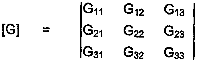
이 비상관 행렬 [G] 및 이의 역행렬 [G]-1 은 마이크로제어기 MC에 의해서 계산되어 가령 재기록가능한 EEPROM(도시되지 않음)과 같은 메모리들 중 하나에 저장된다.This uncorrelated matrix [G] and its inverse [G] -1 are calculated by the microcontroller MC and stored in one of the memories, for example a rewritable EEPROM (not shown).
차량의 정상 동작 모드에서, 행렬 등식 [Ireal] = [G]-1[Imeas]에 의해서 실제 전류 Irealj를 유도하기 위해서 각 도전체 i의 전류 Imeasi 가 전류 트랜스듀서 Ci에 의해서 측정된다.In the normal operating mode of the vehicle, the matrix equation [I real] = [G] -1 [I meas] current of each conductor i to derive the actual current I by I realj measi Is measured by the current transducer C i .
그러므로, 행렬 [G]는 반드시 기하학적이며 특히 센서의 가능한 실장 허용 오차, 특히 버스 바와 센서 간의 거리의 분포를 고려해야 한다.Therefore, the matrix [G] must be geometrical and take into account the possible mounting tolerances of the sensor, in particular the distribution of the distance between the bus bar and the sensor.
따라서, 이 비상관 행렬 [G]로 인해서, 측정될 전류에 대해 외부에 존재하는 전류의 영향, 즉 센서 Ci에 의해서 측정되는 자계의 영향이 제한된다.Thus, this uncorrelated matrix [G] limits the influence of external currents on the current to be measured, ie the influence of the magnetic field measured by the sensor C i .
가역형 전기 기계의 고정자의 3 개의 위상 u,v,w을 갖는 전류에 적용하는 경우에, 실제 전류는 측정된 전류로부터 다음과 같이 획득된다.In the case of application to a current with three phases u, v, w of the stator of the reversible electric machine, the actual current is obtained from the measured current as follows.

바람직하게는 이 전류 측정 계산 방법은 특히 다음과 같은 구성 요소에 의해서 유발되는 측정의 부정확함으로부터 기인되는 오프셋(offset)을 고려하는 추가 캘리브레이션 단계를 포함한다.Preferably this current measurement calculation method comprises an additional calibration step which takes into account the offset resulting from the inaccuracy of the measurement, in particular caused by the following components.
1. 센서 Ci 1. Sensor C i
2. 측정 회로 MES의 구성 요소2. Components of the measuring circuit MES
3. 마이크로제어기 MC의 아날로그 대 디지털 변환기 CAN의 구성 요소3. Components of the analog-to-digital converter CAN of the microcontroller MC
가령, 대략 1000 암페어의 측정 범위에서 12 비트로 측정치가 변환되는 경우에 변환기 CAN은 대략 0.5 암페어에 대응하는 1 비트 내에서 정확할 것이다(2000/212 = 0.5). 대략 100 암페어의 측정 범위의 대해서는, 측정치가 12 비트로 변환되는 경우에 대략 0.5 암페어에 대응하는 1 비트 내에서 변환기 CAN은 정확할 것이다.For example, if a measurement is converted to 12 bits in the measurement range of approximately 1000 amps, the converter CAN will be accurate within 1 bit corresponding to approximately 0.5 amps (2000/2 12 = 0.5). For a measurement range of approximately 100 amps, the converter CAN will be accurate within 1 bit corresponding to approximately 0.5 amps when the measurement is converted to 12 bits.
따라서, 각 도전체 i 내에 공급된 전류의 부재 시에 각 도전체 i에서 측정된 전류와 동일한 원소 Oi를 갖는 오프셋 행렬 [O]에 의해서 오프셋의 카운트가 취해져서, 실제 전류 행렬 [Ireal]이 [Ireal] = [G]-1([Imeas - [O])으로 된다.Thus, in the absence of the current supplied in each conductor i, the count of the offset is taken by an offset matrix [O] having the same element O i as the current measured at each conductor i, so that the actual current matrix [I real ] [I real ] = [G] -1 ([I meas- [O]).
또한, 원소 Oi는 측정된 전류에 대응하는 수치 값일 수 있다.In addition, the element O i may be a numerical value corresponding to the measured current.
3 개의 도전체의 경우에, 오프셋 행렬 [0]은 다음과 같이 주워진다.In the case of three conductors, the offset matrix [0] is given as follows.

이 행렬 [O]은 마이크로제어기 MC에 의해서 계산되어 가령 재기록가능한 EEPROM(도시되지 않음)과 같은 메모리들 중 하나에 저장된다.This matrix [O] is calculated by the microcontroller MC and stored in one of the memories, for example a rewritable EEPROM (not shown).
이러한 캘리브레이션 단계가 고려될 때에, 비상관 행렬 [G]은 다음의 등식에 따라서 계산된다.When this calibration step is considered, the uncorrelated matrix [G] is calculated according to the following equation.
Gij = (Ii - Oi)/Ij 0 [2], 여기서 Oi는 초기화 단계 동안 측정된 전류 Ij 오프셋에 대응한다(여기서, i ≠ j임).G ij = (I i -Oi) / I j 0 [2], where Oi corresponds to the current I j offset measured during the initialization phase, where i ≠ j.
행렬 [G] 및 [0]은 각기 체인 및 오프셋에서 다양한 이득을 포함하며, 이 이득으로 신호가 인해서 제로에 대응하는 값으로 다시 센터링될 수 있다.The matrices [G] and [0] contain various gains in the chain and offset, respectively, with which the signal can be centered back to a value corresponding to zero.
이로써, 센서로 인한 오프셋만이 고려되는 경우에, 비상관 행렬 [G]은 옴으로 표현되고 이어서 역행렬 [G]-1 이 지멘스 단위로 표현된다. 이러한 행렬의 일 실례가 각 센서 Ci가 자신의 해당 버스 바 i로부터 이의 수직 방향으로 대략 2.5 ㎝로 이격되어 있으며 제 1 센서 C1이 제 2 버스 바 2에 대해서 대각선 방향으로 5.5 ㎝로 이격되어 있으며 제 3 버스 바 3에 대해서 대각선 방향으로 10.5 ㎝로 이격되어 있는 경우에 다음과 같이 주워진다.Thus, where only the offset due to the sensor is taken into account, the uncorrelated matrix [G] is expressed in ohms and then the inverse matrix [G] -1 is expressed in Siemens units. One example of such a matrix is that each sensor C i is spaced approximately 2.5 cm from its corresponding bus bar i in its vertical direction and the first sensor C 1 is spaced 5.5 cm in a diagonal direction with respect to the

이에 대응하는 오프셋 행렬 [O]은 다음과 같다.The corresponding offset matrix [O] is as follows.

당연히, 전체 전류 측정 디바이스, 즉 센서와 측정 회로와 아날로그 대 디지털 변환기가 캘리브레이션된다. 이 경우에, 비상관 행렬 [G]의 단위는 암페어 마이크로제어기 단위일 것이다.Naturally, the entire current measurement device, i.e. the sensor and measurement circuitry, and the analog-to-digital converter are calibrated. In this case, the unit of uncorrelated matrix [G] would be the ampere microcontroller unit.
이로써, 캘리브레이션에 따라서, 실제 전류 Ireal이 상이한 단위를 갖는다. 가령, 이 단위는 캘리브레이션이 오직 센서 Ci에만 관련되면 전압일 것이고, 캘리브레이션이 센서 Ci 및 측정 회로 MES에 관련되면 주파수일 것이며, 캘리브레이션이 센서 Ci와 측정 회로 MES와 아날로그 대 디지털 변화기 CAN에 관련되면 분해능을 갖는 수치일 것이다. Thus, according to the calibration, the actual current I real has different units. For example, this unit would be voltage if calibration is only relevant to sensor C i , and calibration is sensor C i And if it relates to the measuring circuit MES, it will be a frequency, and if the calibration is related to the sensor C i and the measuring circuit MES and the analog-to-digital converter CAN, it will be a numerical value with resolution.
이로써, 이득 행렬로서 지칭될 수도 있는 비상관 행렬 [G] 및 오프셋 행렬 [O]로 인해서 전체 측정 디바이스의 구성 요소로 인해서 기인되는 센서의 상관 문제와 측정의 부정확성 문제를 해결함으로써 전류 측정 디바이스 전체를 캘리브레션할 수 있다. 이는 비상관 벡터와 오프셋 벡터 중 어느 하나만을 사용하는 경우에는 달성되지 않는다.This solves the entire current measurement device by solving the sensor's correlation problem and measurement inaccuracy caused by the components of the overall measurement device due to the uncorrelated matrix [G] and the offset matrix [O], which may also be referred to as gain matrices. It can be calibrated. This is not achieved if only one of the uncorrelated vector and the offset vector is used.
도 4는 가역형 전기 기계의 고정자의 3 상 전류 Iu, Iv 및 Iw의 수치 분해능에 대해서 본 발명이 사용될 수 있는 방식을 도시하고 있다.4 shows how the present invention can be used for the numerical resolution of the three phase currents I u , I v and I w of the stator of a reversible electric machine.
예시적인 실시예에서, 전류 측정 방법은 투영 행렬 [C]에 의해서 n 상 기준 프레임의 측정된 실제 전류 Ireal를 2 상 기준 프레임으로 변환하는 보충 단계를 포함한다.In an exemplary embodiment, the current measuring method includes a supplementary step of converting the measured actual current I real of the n-phase reference frame into a two-phase reference frame by the projection matrix [C].
이 보충 단계는 교류 발전기/스타터 기계의 고정자의 위상 Φ에서 전류를 계산하는 것과 제어하는 것을 단순화시키기 위해서 수행된다.This replenishment step is performed to simplify the calculation and control of the current in the phase Φ of the stator of the alternator / starter machine.
n = 3인 경우에, 3 상 전류 Iu, Iv 및 Iw를 2 상 전류 Iα 및 Iβ로 변환하는 이른바 Clark 행렬 또는 Concordia 행렬로 알려진 행렬과 같은 행렬에 의해서 프로세싱된다. 고정자 전류를 조정하기 위해서 이 2 상 전류는 수치 조정 유닛에 인가된다. 이러한 방식으로 다음과 같은 바가 획득된다.In the case of n = 3, it is processed by a matrix, such as a so-called Clark matrix or a matrix known as Concordia matrix, which converts three-phase currents I u , I v and I w into two-phase currents I α and I β . This two-phase current is applied to the numerical adjustment unit to adjust the stator current. In this way, the following is obtained.

여기서, Ih 는 단극 성분(homopolar component)으로서 [regul] = [C]-1 [Ireal]이다.Where I h Is a homopolar component [ regul ] = [C] -1 [I real ].
이 단극 성분은 축 Oβ에 대해 수직인 제 3 축 상의 3 상 전류들의 합에 대응한다.This monopolar component corresponds to the sum of the three phase currents on the third axis perpendicular to the axis Oβ.
본 기술 분야의 당업자에게 잘 알려진 델타(delta)로의 위상의 와인딩(winding)의 경우에, 단극 성분은 전류의 내부 순환에 대응한다.In the case of the winding of the phase to delta, which is well known to those skilled in the art, the unipolar component corresponds to the internal circulation of current.
본 기술 분야의 당업자에게 잘 알려진 스타(star)로의 위상의 와인딩의 경우에, 단극 성분은 3 개의 위상 간의 공통 지점인 고정자의 중립 지점에 대응한다. 이 중립 지점이 접속되지 않으면, 단극 성분은 중립적이다.In the case of winding of a phase into a star well known to those skilled in the art, the monopolar component corresponds to the neutral point of the stator, which is a common point between the three phases. If this neutral point is not connected, the unipolar component is neutral.
행렬 [C] 및 그의 역행렬 [C]-1 은 가령 재기록가능하지 않은 ROM 또는 재기록가능한 EEPROM(도시되지 않음)와 같은 마이크로제어기 MC의 메모리 중 하나에 저장된다.Matrix [C] and its inverse [C] -1 are stored in one of the memories of the microcontroller MC, such as non-rewritable ROM or rewritable EEPROM (not shown).
도 5는 각도를 표시하기 위해서 전류 Imeasu가 대응하는 고정자의 제 1 위상 Φu의 축을 취하는 시스템(α, β, O)에서 3 상 전류 Iu, Iv 및 IW의 투영을 도시한다. FIG. 5 shows the projection of three phase currents I u , I v and I W in a system α, β, O where the current I measu takes the axis of the first phase Φ u of the corresponding stator to indicate the angle.
사용가능한 Concordia 투영 행렬의 실례에 따르면 [C] 및 [C]-1 은 다음과 같다.According to an example of the Concordia projection matrix that can be used, [C] and [C] -1 are as follows.

사용가능한 Clark 투영 행렬의 실례에 따르면 [C] 및 [C]-1 은 다음과 같다.According to an example of a Clark projection matrix that can be used, [C] and [C] -1 are as follows.

이러한 투영 행렬의 계수는 상수이지만 3 상 전류의 회전 방향, 3 상 전류의 강도 등과 같은 통상적인 사항의 함수이다. 따라서, 다른 표준화 요소를 가질 수도 있다.The coefficient of this projection matrix is constant, but it is a function of conventional matters such as the direction of rotation of the three-phase current, the strength of the three-phase current, and the like. Thus, it may have other standardization elements.
이로써, 2 상 전류 Iα 및 Iβ는 도 2에 도시된 디바이스에서 측정된 전류 Imeas로부터 단일 행렬 [M] = [C]-1·[G]-1 = [G·C]-1 에 의해서 직접적으로 획득될 수 있다.Thus, the two-phase currents I α and I β depend on a single matrix [M] = [C] −1 · [G] −1 = [G · C] −1 from the current I meas measured in the device shown in FIG. Can be obtained directly.
다음과 같은 등식이 있다.Here is the equation:
![]()
![]()
두 행렬 [C]-1 과 [G]-1의 적(product)은 기계의 회전, 즉 고정자-회전자 각도 θ가 고려되지 않기 때문에 오프라인으로 실행된다.The product of the two matrices [C] -1 and [G] -1 runs offline because the machine's rotation, i.e. the stator-rotor angle θ, is not taken into account.
기계가 기계의 기준 프레임에서 동작하기를 원하는 경우에, 말하자면 고정자-회전자 각도 θ를 고려하고 이로써 전류의 계산을 온라인으로, 즉 실시간으로 수행하기 원하는 경우에, 축 Oα 및 Oβ가 제 1 위상 Φu의 축에 대해서 각도 θ 만큼 오프셋된다고 가정된다. 새로운 축은 본 기술 분야의 당업자에게 잘 알려진 바와 같은 횡축(각 극 사이의 경계선)(quadrature axis) Oq 및 종축(direct axis) Od이다. 이로써, 다음과 같은 회전 행렬 [R]을 인가함으로써 시스템(α,β, θ)에서 시스템(d,q,O)로 변경된다.If the machine wishes to operate in the machine's reference frame, that is to say, taking into account the stator-rotor angle θ and thereby carrying out the calculation of the current online, i.e. in real time, the axes Oα and Oβ are the first phase Φ It is assumed to be offset by the angle θ with respect to the axis of u . The new axes are the horizontal axis (quadrature axis) O q and the direct axis O d as is well known to those skilled in the art. Thus, by applying the following rotation matrix [R], the system (α, β, θ) is changed from the system (d, q, O).

이로써 다음이 성립된다.This holds for:

이는 변화시키면 다음과 같다.This is changed as follows.

투영 행렬(Concordia 또는 Clark)과 상기 회전 행렬 [R]의 적인 Park 행렬 [P]로 알려진 다음과 같은 변환 행렬이 사용된다.The following transformation matrix known as the projection matrix (Concordia or Clark) and the Park matrix [P], the enemy of the rotation matrix [R], is used.

이로써, Park 행렬의 역행렬 [P]-1 은 [R]-1 ·[C]-1 이 되고, 오프셋 행렬 [0]이 사용되는 경우에 상기 역행렬 [P]-1 이 측정된 전류 Imeas 에 인가되어서 새로운 전류 Idq가 다음과 같이 획득된다.Thus, the inverse [P] -1 of the Park matrix becomes [R] -1 · [C] -1 , and the inverse [P] -1 is applied to the measured current I meas when the offset matrix [0] is used. By applying a new current I dq is obtained as follows.

이러한 Park 변환 행렬로 인해서 기계 전류를 더욱 효율적으로 제어할 수 있다. 이러한 방식으로, 가변 또는 교대로 변경되는 정량 대신에 연속적 정량이 획득되는데, 이러한 연속 정량은 조정하기가 더 용이하다.This Park transformation matrix allows for more efficient control of the mechanical current. In this way, continuous quantification is obtained instead of variable or alternating quantitation, which is easier to adjust.
인버터-정류기의 정상 동작 이전에, 행렬 [G], [O] 및 [M]이 단번에 확실하게 마이크로제어기 MC에 의해서 계산된다.Prior to the normal operation of the inverter-rectifier, the matrices [G], [O] and [M] are reliably calculated by the microcontroller MC at once.
이로써, 본 발명의 전류 측정 방법은 컴퓨터에 의해서 수행되는 비상관 행렬의 이론적 계산에 비해서 소정의 이점을 갖는데, 이러한 이론적 계산은 센서에 인접하는 구성 요소들로 인한 간섭을 파악하지 못하여 센서가 부정확하다. 또한, 본 발명에 따른 방법은 컴퓨터에 의한 계산보다 더 간단하다. 마지막으로, 본 발명에 따른 방법에 의해서 다양한 도전체 내의 전류 측정의 완벽한 비상관이 가능해진다. 이러한 비상관은 도전체에서 측정된 전류와 자속 간의 비상관, 즉 전류의 비상관과는 다른 목적을 추구하는 비상관과는 상이하다. Thus, the current measuring method of the present invention has certain advantages over the theoretical calculation of the uncorrelated matrix performed by a computer, which is inaccurate because the sensor does not grasp interference due to components adjacent to the sensor. . In addition, the method according to the invention is simpler than computation by computer. Finally, the method according to the invention enables complete uncorrelation of current measurements in various conductors. This non-correlation differs from the non-correlation between the current measured in the conductor and the magnetic flux, ie, the non-correlation that pursues a different purpose than the non-correlation of the current.
본 발명에 따른 방법은 회전형 전기 기계에서 전류를 측정하는 분야에만 적용되는 것이 아니라 다수의 전류를 측정할 시에 공간이 제약되어 있어서 측정치들 간의 상관이 발생되고 이로써 비상관을 필요로 하는 가령 차량 내의 배터리 관리 시스템(BMS) 또는 DC/DC 변환기의 경우와 같은 임의의 용도로 사용될 수 있다. 배터리 관리 시스템은 통상적으로 배터리 및 공기 조절 시스템 및 하이 파이 관리 시스템과 같은 전력 소비 구성 요소에 접속된 다양한 커넥터를 포함하는 하우징을 포함하고 있어서 특히 그러하다. 상기 배터리와 전력 소비 구성 요소의 보정된 동작을 위해서 이들을 통과하는 전류를 정확하게 측정할 필요가 있다.The method according to the invention is not only applied to the field of measuring current in a rotary electric machine but also the space is limited when measuring a large number of currents so that a correlation between the measurements is generated, thereby requiring an uncorrelated vehicle, for example a vehicle. It can be used for any purpose, such as in the case of a battery management system (BMS) or a DC / DC converter. Battery management systems typically include housings that include various connectors that are typically connected to power consumption components such as battery and air conditioning systems and hi-fi management systems. For corrected operation of the battery and power dissipation components it is necessary to accurately measure the current passing through them.
이와 마찬가지로, DC/DC 변환기는 전류가 통과하는 다양한 셀 또는 구성 요소 및 측정될 필요가 있는 입력 전력 및 출력 전력이 포함하기 때문에 특히 그러하다. DC/DC 변환기는 배터리는 42 볼트로 존재하고 전력 소비 구성 요소는 12 볼트로 존재하는 42 볼트 차량에서 사용될 수 있으며, 상기 변환기는 42 볼트를 12 볼트로 변화시킬 수 있다.Similarly, DC / DC converters are especially so because they include the various cells or components through which current passes and the input and output power that needs to be measured. The DC / DC converter can be used in a 42 volt vehicle where the battery is at 42 volts and the power consumption component is at 12 volts, which can convert 42 volts to 12 volts.
Claims (13)
Applications Claiming Priority (2)
| Application Number | Priority Date | Filing Date | Title |
|---|---|---|---|
| FR0407261A FR2872580B1 (en) | 2004-06-30 | 2004-06-30 | METHOD FOR MEASURING THE ELECTRICAL CURRENT IN A PLURALITY OF CONDUCTORS |
| FR0407261 | 2004-06-30 |
Publications (1)
| Publication Number | Publication Date |
|---|---|
| KR20070037717A true KR20070037717A (en) | 2007-04-06 |
Family
ID=34947670
Family Applications (1)
| Application Number | Title | Priority Date | Filing Date |
|---|---|---|---|
| KR1020067027708A KR20070037717A (en) | 2004-06-30 | 2005-06-30 | Method for measuring electric current in a plurality of conductors |
Country Status (11)
| Country | Link |
|---|---|
| US (1) | US7895004B2 (en) |
| EP (1) | EP1766422B1 (en) |
| JP (1) | JP2008504546A (en) |
| KR (1) | KR20070037717A (en) |
| CN (1) | CN1997899A (en) |
| BR (1) | BRPI0512279A (en) |
| CA (1) | CA2567607A1 (en) |
| FR (1) | FR2872580B1 (en) |
| MX (1) | MXPA06014537A (en) |
| RU (1) | RU2007103364A (en) |
| WO (1) | WO2006010865A1 (en) |
Cited By (2)
| Publication number | Priority date | Publication date | Assignee | Title |
|---|---|---|---|---|
| KR100934448B1 (en) * | 2007-10-17 | 2009-12-29 | 한국산업기술대학교산학협력단 | Non-contact measuring method of current flowing in a plurality of superconducting wires connected in parallel |
| KR101488690B1 (en) * | 2013-07-31 | 2015-02-04 | 주식회사 레티그리드 | Method and current measuring device to measure current by cancelling adjacent current interference |
Families Citing this family (25)
| Publication number | Priority date | Publication date | Assignee | Title |
|---|---|---|---|---|
| DE102006050781A1 (en) | 2006-10-27 | 2008-04-30 | Ast Gmbh | Device for the spatial positioning of a device |
| GB0723621D0 (en) * | 2007-12-04 | 2008-01-09 | Ecoauditors Ltd | Measuring alternating current flowing through an electricity supply distribution unit |
| US9222992B2 (en) | 2008-12-18 | 2015-12-29 | Infineon Technologies Ag | Magnetic field current sensors |
| US8717016B2 (en) * | 2010-02-24 | 2014-05-06 | Infineon Technologies Ag | Current sensors and methods |
| US8760149B2 (en) | 2010-04-08 | 2014-06-24 | Infineon Technologies Ag | Magnetic field current sensors |
| WO2011143159A1 (en) * | 2010-05-10 | 2011-11-17 | D&R Technology, Llc | System and method for interpreting a signal from a transducer |
| WO2011148720A1 (en) * | 2010-05-25 | 2011-12-01 | 富士通株式会社 | Power strip current-correction-equation calculation method, current measurement method, power measurement method, manufacturing method, power strip, and current measurement system |
| US8680843B2 (en) * | 2010-06-10 | 2014-03-25 | Infineon Technologies Ag | Magnetic field current sensors |
| WO2012003426A2 (en) | 2010-07-02 | 2012-01-05 | Reynolds Brett S | Apparatus for calibrated non-invasive measurement of electrical current |
| US8283742B2 (en) | 2010-08-31 | 2012-10-09 | Infineon Technologies, A.G. | Thin-wafer current sensors |
| US8975889B2 (en) | 2011-01-24 | 2015-03-10 | Infineon Technologies Ag | Current difference sensors, systems and methods |
| US8963536B2 (en) | 2011-04-14 | 2015-02-24 | Infineon Technologies Ag | Current sensors, systems and methods for sensing current in a conductor |
| DE112012003092T5 (en) * | 2011-10-17 | 2014-07-24 | Aisin Aw Co., Ltd. | Current detector |
| FR2982672B1 (en) * | 2011-11-10 | 2014-03-14 | Univ Lyon 1 Claude Bernard | DEVICE FOR MEASURING CURRENTS IN THE CONDUCTORS OF A SHEET CABLE OF A POLYPHASE NETWORK |
| EP2653875B1 (en) * | 2012-04-20 | 2014-09-10 | ABB Technology AG | Current transducer of the rogowski type and arrangement for measuring a current |
| KR101297200B1 (en) * | 2013-04-04 | 2013-08-29 | 주식회사 레티그리드 | Point detecting type current measuring device having function of compensating interference by adjacent bus bar |
| GB2513866A (en) * | 2013-05-07 | 2014-11-12 | Sevcon Ltd | Current transducer |
| US10043427B2 (en) * | 2014-09-05 | 2018-08-07 | Semiconductor Energy Laboratory Co., Ltd. | Matrix device, measurement method of characteristics thereof, and driving method thereof |
| US9797931B2 (en) * | 2014-09-05 | 2017-10-24 | Semiconductor Energy Laboratory Co., Ltd. | Matrix device, measurement method of characteristics thereof, and driving method thereof |
| WO2016046692A1 (en) | 2014-09-26 | 2016-03-31 | 株式会社半導体エネルギー研究所 | Matrix device, and drive method and properties measurement method for same |
| US9804719B2 (en) | 2014-10-23 | 2017-10-31 | Semiconductor Energy Laboratory Co., Ltd. | Electronic device |
| US10330708B2 (en) * | 2016-01-07 | 2019-06-25 | Hitachi Metals, Ltd. | Current detection device and correction factor calculation method |
| US10598700B2 (en) * | 2016-12-30 | 2020-03-24 | Texas Instruments Incorporated | Magnetic field-based current measurement |
| CN106872759B (en) * | 2017-02-24 | 2019-04-05 | 广东顺德工业设计研究院(广东顺德创新设计研究院) | Current path detection device and current path detection method |
| EP3385727A1 (en) * | 2017-04-07 | 2018-10-10 | Siemens Aktiengesellschaft | Method for measuring a current and current measurement device |
Family Cites Families (16)
| Publication number | Priority date | Publication date | Assignee | Title |
|---|---|---|---|---|
| DE2845155C2 (en) | 1978-10-17 | 1986-10-09 | Siemens AG, 1000 Berlin und 8000 München | Device for measuring the conductor currents in multi-phase medium-voltage systems |
| US4418312A (en) * | 1981-10-23 | 1983-11-29 | Bell Telephone Laboratories, Incorporated | Apparatus for testing multi-conductor cables |
| FR2634897A1 (en) * | 1988-07-26 | 1990-02-02 | Alsthom | DEVICE FOR MEASURING PHASE CURRENTS OF A THREE-PHASE INSTALLATION |
| EP0482271B1 (en) * | 1990-10-24 | 1996-02-21 | International Business Machines Corporation | Current-to-voltage converter with low noise, wide bandwidth and high dynamic range |
| DE4238356A1 (en) | 1992-11-13 | 1994-05-19 | Abb Patent Gmbh | Method and device for determining the conductor currents of a multi-conductor system |
| GB9500974D0 (en) * | 1995-01-18 | 1995-03-08 | Horstmann Timers & Controls | Electricity measurement apparatus |
| US5907244A (en) * | 1996-08-02 | 1999-05-25 | Automation Technology, Inc. | Method and apparatus for detecting winding errors in an electric motor stator |
| EP0874244B1 (en) * | 1997-04-19 | 2002-01-30 | LUST ANTRIEBSTECHNIK GmbH | Procedure and apparatus for measuring electric currents in conductors |
| DE19741417B4 (en) * | 1997-09-19 | 2004-02-26 | Klaus Bruchmann | Current measuring device with Hall sensor |
| DE29804737U1 (en) * | 1998-03-17 | 1998-05-07 | Ssg Halbleiter Vertriebs Gmbh | Measuring device for determining a current flowing through an electrical conductor |
| DE19813890A1 (en) * | 1998-03-28 | 1999-09-30 | Abb Research Ltd | Current measurement method |
| DE19910801B4 (en) * | 1999-03-11 | 2004-06-03 | Fraunhofer-Gesellschaft zur Förderung der angewandten Forschung e.V. | Device and method for measuring current |
| US6753628B1 (en) * | 1999-07-29 | 2004-06-22 | Encap Motor Corporation | High speed spindle motor for disc drive |
| US6285191B1 (en) * | 1999-10-08 | 2001-09-04 | Alliedsignal Inc. | Measurement of current in a vehicle using battery cable as a shunt |
| JP4575153B2 (en) * | 2002-06-18 | 2010-11-04 | 旭化成エレクトロニクス株式会社 | Current measuring method and current measuring apparatus |
| JP4103713B2 (en) * | 2003-07-18 | 2008-06-18 | 株式会社デンソー | Current detector |
-
2004
- 2004-06-30 FR FR0407261A patent/FR2872580B1/en not_active Expired - Fee Related
-
2005
- 2005-06-30 MX MXPA06014537A patent/MXPA06014537A/en not_active Application Discontinuation
- 2005-06-30 US US11/570,931 patent/US7895004B2/en not_active Expired - Fee Related
- 2005-06-30 JP JP2007518647A patent/JP2008504546A/en active Pending
- 2005-06-30 RU RU2007103364/28A patent/RU2007103364A/en not_active Application Discontinuation
- 2005-06-30 EP EP05783755.1A patent/EP1766422B1/en not_active Not-in-force
- 2005-06-30 CN CNA2005800216931A patent/CN1997899A/en active Pending
- 2005-06-30 CA CA002567607A patent/CA2567607A1/en not_active Abandoned
- 2005-06-30 BR BRPI0512279-1A patent/BRPI0512279A/en not_active Application Discontinuation
- 2005-06-30 WO PCT/FR2005/001664 patent/WO2006010865A1/en active Application Filing
- 2005-06-30 KR KR1020067027708A patent/KR20070037717A/en not_active Application Discontinuation
Cited By (2)
| Publication number | Priority date | Publication date | Assignee | Title |
|---|---|---|---|---|
| KR100934448B1 (en) * | 2007-10-17 | 2009-12-29 | 한국산업기술대학교산학협력단 | Non-contact measuring method of current flowing in a plurality of superconducting wires connected in parallel |
| KR101488690B1 (en) * | 2013-07-31 | 2015-02-04 | 주식회사 레티그리드 | Method and current measuring device to measure current by cancelling adjacent current interference |
Also Published As
| Publication number | Publication date |
|---|---|
| CA2567607A1 (en) | 2006-02-02 |
| FR2872580B1 (en) | 2006-09-01 |
| JP2008504546A (en) | 2008-02-14 |
| WO2006010865A1 (en) | 2006-02-02 |
| BRPI0512279A (en) | 2008-02-26 |
| RU2007103364A (en) | 2008-08-10 |
| EP1766422A1 (en) | 2007-03-28 |
| FR2872580A1 (en) | 2006-01-06 |
| EP1766422B1 (en) | 2018-02-28 |
| MXPA06014537A (en) | 2007-03-23 |
| US7895004B2 (en) | 2011-02-22 |
| US20080312854A1 (en) | 2008-12-18 |
| CN1997899A (en) | 2007-07-11 |
Similar Documents
| Publication | Publication Date | Title |
|---|---|---|
| KR20070037717A (en) | Method for measuring electric current in a plurality of conductors | |
| US4672288A (en) | Torque controller for an AC motor drive and AC motor drive embodying the same | |
| KR20010066851A (en) | Active reduction of torque irregularities in rotating machines | |
| US4000464A (en) | Arrangement for detecting ground leaks in the rotor circuit of a brushless synchronous machine excited by rotating rectifiers | |
| US5652505A (en) | Power consumption measurement device for a multiphase alternating current system | |
| HU226336B1 (en) | Method for regulating a three-phase machine without a mechanical rotary transducer | |
| EP1393434B1 (en) | A method associated with controlling a synchronous machine | |
| JP3456151B2 (en) | Multi-circuit wattmeter and multi-circuit watt-hour meter | |
| JP3092839B2 (en) | Inverter device with constant measurement setting function | |
| JP2004505598A (en) | A method for estimating pole wheel position in claw-pole machines | |
| Sushma et al. | DQ modeling of induction motor for virtual flux measurement | |
| WO2022201344A1 (en) | Magnetic gap length estimating device, magnetic gap length estimating method, and driving device for dynamo-electric machine | |
| JP2850096B2 (en) | Inverter control method with constant measurement setting function | |
| Slavov | Adaptive observer of resistance in sensorless estimation of speed and position in brushless DC electric motor | |
| JP3329672B2 (en) | Induction motor constant measuring device | |
| JPH0141945B2 (en) | ||
| Caruso et al. | An accurate measurement procedure of power losses variations in electrical drives | |
| JPH0336920A (en) | Ground protector for electrical rotary machine | |
| KR20040087160A (en) | Apparatus for measuring mutual inductance of induction motor | |
| EP0548676B1 (en) | Flux regulator particularly for drivers of asynchronous electric motors | |
| CN117434336A (en) | Positioning and correction of current sensing devices | |
| JP3265768B2 (en) | Variable speed device | |
| Koegl et al. | A DEMONSTRATION OF SENSORLESS TORQUE MEASUREMENT | |
| SU902195A1 (en) | Method of adjusting automatic regulator for three-phase synchronous machine | |
| White et al. | Compensation for the skin effect in vector-controlled induction motor drive systems |
Legal Events
| Date | Code | Title | Description |
|---|---|---|---|
| WITN | Application deemed withdrawn, e.g. because no request for examination was filed or no examination fee was paid |