KR200462380Y1 - Wire arrangement - Google Patents
Wire arrangement Download PDFInfo
- Publication number
- KR200462380Y1 KR200462380Y1 KR2020120003697U KR20120003697U KR200462380Y1 KR 200462380 Y1 KR200462380 Y1 KR 200462380Y1 KR 2020120003697 U KR2020120003697 U KR 2020120003697U KR 20120003697 U KR20120003697 U KR 20120003697U KR 200462380 Y1 KR200462380 Y1 KR 200462380Y1
- Authority
- KR
- South Korea
- Prior art keywords
- spiral tube
- spiral
- wire
- insertion hole
- present
- Prior art date
Links
Images


Classifications
-
- H—ELECTRICITY
- H04—ELECTRIC COMMUNICATION TECHNIQUE
- H04R—LOUDSPEAKERS, MICROPHONES, GRAMOPHONE PICK-UPS OR LIKE ACOUSTIC ELECTROMECHANICAL TRANSDUCERS; DEAF-AID SETS; PUBLIC ADDRESS SYSTEMS
- H04R1/00—Details of transducers, loudspeakers or microphones
- H04R1/06—Arranging circuit leads; Relieving strain on circuit leads
-
- H—ELECTRICITY
- H04—ELECTRIC COMMUNICATION TECHNIQUE
- H04R—LOUDSPEAKERS, MICROPHONES, GRAMOPHONE PICK-UPS OR LIKE ACOUSTIC ELECTROMECHANICAL TRANSDUCERS; DEAF-AID SETS; PUBLIC ADDRESS SYSTEMS
- H04R1/00—Details of transducers, loudspeakers or microphones
- H04R1/10—Earpieces; Attachments therefor ; Earphones; Monophonic headphones
- H04R1/1033—Cables or cables storage, e.g. cable reels
-
- A—HUMAN NECESSITIES
- A45—HAND OR TRAVELLING ARTICLES
- A45F—TRAVELLING OR CAMP EQUIPMENT: SACKS OR PACKS CARRIED ON THE BODY
- A45F2200/00—Details not otherwise provided for in A45F
- A45F2200/05—Holder or carrier for specific articles
- A45F2200/0575—Portable tools
Abstract
The present invention relates to a selection stopper that can be adjusted to a convenient length by increasing or decreasing the wire connected to headphones or earphones.
The present invention, in the selector for arranging the electric wire, a hollow insertion hole is formed in the spiral tube made of a spiral shape made of a spiral material made of an elastic material so that the electric wire is inserted so that the electric wire is stretched or reduced with the spiral pipe In addition, the spiral tube is inserted into the insertion hole through the incision line formed by the incision line continuously formed along the spiral direction.
Description
The present invention relates to a selector, and more particularly, to a selector that can be adjusted to a convenient length of use by increasing or decreasing the wire connected to headphones or earphones.
As is well known, the headphone is compressed to the ear to listen to the voice signal, and the earphone is inserted into the ear to listen to the voice signal. The headphones and the earphone can listen to the small voice signal and do not harm the third party. The advantage is that you can listen to the signal.
In addition, wires are connected to headphones and earphones, and the wires are provided with connection terminals, which are connected to connection terminals of terminals including mobile phones or MP3s. Is formed.
However, if the wire length of the headphone or earphone is too short, the user cannot carry or listen to the voice signal by carrying the terminal on the pocket or the like. There was a problem.
In recent years, in order to solve this problem, a bobbin for controlling the length of the wire by winding it is widely used.
However, the bobbin winding is inconvenient because the wires must be wound or unrolled in order to adjust the length of the wires, and if the wires are wound or unwound using springs or the like, problems such as economical increase due to the increase of various accessories There was this.
The present invention is devised to solve the conventional problems as described above, the object of the present invention is to provide a selector that can be adjusted to a convenient length to use by simply increasing or reducing the wire connected to headphones or earphones.
In order to achieve the above object, the present invention, in the selector to organize the wires of the headphone or earphone, the hollow insertion hole is formed so that the wire is inserted in the spiral tube formed of a spiral shape made of an elastic material, the wire is The spiral tube is elastically stretched or contracted with the spiral tube, and the wire is inserted into the insertion hole through the incision line which is continuously formed by cutting incision along the spiral direction.
At this time, the cut line is preferably formed along the inner central portion of the spiral tube.
According to the present invention embodied by the above means, the wire of the headphone or earphone inserted into the insertion hole of the spiral tube is normally kept in a compressed state and pulls both sides of the wire, so that the wire stretches elastically with the spiral tube, the user This is a very useful effect that can be arranged while easily adjusting the length of the wire.
In addition, according to the present invention, since the incision is formed in the inner central portion of the spiral tube is not exposed from the outside with the spiral has an effect that can provide a beautiful appearance.
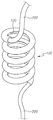
1 is a perspective view according to an embodiment of the present invention.
2 is a sectional view taken along the line AA in Fig.
Figure 3 is a perspective view of the wire inserted into the insertion hole of the spiral tube according to an embodiment of the present invention.
4 is an operation of the wire is inserted into the insertion hole of the spiral tube according to an embodiment of the present invention.
5 to 7 is an operation diagram according to an embodiment of the present invention.
8 is a front view showing another embodiment of the spiral tube according to an embodiment of the present invention.
Hereinafter, with reference to the accompanying drawings, preferred embodiments of the present invention will be described in detail.
1 is a view showing a perspective view of the
FIG. 2 is a cross-sectional view taken along line AA of FIG. 1, and as shown in FIG. 2, the
In addition, a
In addition, as shown in FIGS. 1 and 2, the
The
When described in detail with reference to the accompanying drawings the overall operation of the present invention configured as described above.
First, as shown in FIG. 4, when the
5 is a front view of a state in which the
Subsequently, FIG. 6 is a front view of a state in which the
Next, FIG. 7 is a front view of the
That is, the
It will be understood by those skilled in the art that various changes in form and details may be made therein without departing from the spirit and scope of the invention as defined by the appended claims and their equivalents. You will understand. If such improvement, change, substitution and addition is carried out within the scope of the following utility model registration claims, it is obvious that the technical idea also belongs to the present invention.
100: iris pin 110: spiral tube
120: insertion hole 130: incision
200: wires
Claims (2)
A spiral insertion hole is formed in the spiral tube formed in a spiral shape and made of an elastic material so that the wire is inserted, and the wire is elastically stretched or shrunk with the spiral tube,
The spiral tube has a selector, characterized in that the incision line cut along the spiral direction is continuously formed and the wire is inserted into the insertion hole through the gap between the incision line.
The cut line is characterized in that formed along the inner central portion of the spiral tube.
Priority Applications (1)
| Application Number | Priority Date | Filing Date | Title |
|---|---|---|---|
| KR2020120003697U KR200462380Y1 (en) | 2012-05-04 | 2012-05-04 | Wire arrangement |
Applications Claiming Priority (1)
| Application Number | Priority Date | Filing Date | Title |
|---|---|---|---|
| KR2020120003697U KR200462380Y1 (en) | 2012-05-04 | 2012-05-04 | Wire arrangement |
Publications (1)
| Publication Number | Publication Date |
|---|---|
| KR200462380Y1 true KR200462380Y1 (en) | 2012-09-07 |
Family
ID=47074429
Family Applications (1)
| Application Number | Title | Priority Date | Filing Date |
|---|---|---|---|
| KR2020120003697U KR200462380Y1 (en) | 2012-05-04 | 2012-05-04 | Wire arrangement |
Country Status (1)
| Country | Link |
|---|---|
| KR (1) | KR200462380Y1 (en) |
Cited By (2)
| Publication number | Priority date | Publication date | Assignee | Title |
|---|---|---|---|---|
| KR101263645B1 (en) | 2012-11-21 | 2013-05-21 | 임성식 | Easy-tying and easy-untying earphone and wire having tieing device |
| US10257599B2 (en) | 2015-11-23 | 2019-04-09 | International Business Machines Corporation | Slack and strain control mechanism |
Citations (1)
| Publication number | Priority date | Publication date | Assignee | Title |
|---|---|---|---|---|
| KR200397507Y1 (en) | 2005-06-24 | 2005-10-05 | 우양기 | String fixing equipment by used earphone and headphone |
-
2012
- 2012-05-04 KR KR2020120003697U patent/KR200462380Y1/en not_active IP Right Cessation
Patent Citations (1)
| Publication number | Priority date | Publication date | Assignee | Title |
|---|---|---|---|---|
| KR200397507Y1 (en) | 2005-06-24 | 2005-10-05 | 우양기 | String fixing equipment by used earphone and headphone |
Cited By (2)
| Publication number | Priority date | Publication date | Assignee | Title |
|---|---|---|---|---|
| KR101263645B1 (en) | 2012-11-21 | 2013-05-21 | 임성식 | Easy-tying and easy-untying earphone and wire having tieing device |
| US10257599B2 (en) | 2015-11-23 | 2019-04-09 | International Business Machines Corporation | Slack and strain control mechanism |
Similar Documents
| Publication | Publication Date | Title |
|---|---|---|
| US8290193B2 (en) | Headphones with reduced tangling and methods | |
| US8345913B2 (en) | Headphone with restraint and methods | |
| US8383941B2 (en) | Headphone tangle prevention apparatus | |
| KR101263645B1 (en) | Easy-tying and easy-untying earphone and wire having tieing device | |
| US9429257B2 (en) | Tangle-prevention sleeve for headphone/earphone wire | |
| KR101142400B1 (en) | Earphone for preventing twisting of strings using permanent magnetic | |
| KR200462380Y1 (en) | Wire arrangement | |
| KR200462710Y1 (en) | An earphone which has a variable extension line | |
| CN202818562U (en) | Earphone capable of serving as winding bracket | |
| CN205545811U (en) | Antiwind knotting device of earphone | |
| CN205610886U (en) | Can accomodate extension formula earphone of line | |
| KR200462974Y1 (en) | Line wider for earphones | |
| KR20090012915U (en) | an earphone | |
| CN205039994U (en) | Multifunctional headset | |
| CN105992083A (en) | Wire-windable earphone | |
| US20160029113A1 (en) | Wire organizer | |
| CN201937799U (en) | Retractable headset | |
| CN208657029U (en) | It is a kind of to facilitate the earphone winder for winding more set of headphones | |
| CN207869326U (en) | A kind of antiwind portable device of Novel earphone | |
| KR101185806B1 (en) | Earphone having a function preventable to twist | |
| CN205195915U (en) | Novel earphone | |
| CN202503641U (en) | Earphone | |
| CN206775702U (en) | A kind of earphone for preventing earphone cord from being wound | |
| CN208128487U (en) | A kind of movement bluetooth headset preventing wire winding and waved | |
| CN206226663U (en) | A kind of monaural coiling earphone and ears coiling earphone |
Legal Events
| Date | Code | Title | Description |
|---|---|---|---|
| A201 | Request for examination | ||
| A302 | Request for accelerated examination | ||
| E701 | Decision to grant or registration of patent right | ||
| REGI | Registration of establishment | ||
| FPAY | Annual fee payment |
Payment date: 20150930 Year of fee payment: 4 |
|
| LAPS | Lapse due to unpaid annual fee |