KR102055644B1 - Automatic constant temperature dehumidifier - Google Patents
Automatic constant temperature dehumidifier Download PDFInfo
- Publication number
- KR102055644B1 KR102055644B1 KR1020197015874A KR20197015874A KR102055644B1 KR 102055644 B1 KR102055644 B1 KR 102055644B1 KR 1020197015874 A KR1020197015874 A KR 1020197015874A KR 20197015874 A KR20197015874 A KR 20197015874A KR 102055644 B1 KR102055644 B1 KR 102055644B1
- Authority
- KR
- South Korea
- Prior art keywords
- air
- heat
- evaporator
- module
- condenser
- Prior art date
- Legal status (The legal status is an assumption and is not a legal conclusion. Google has not performed a legal analysis and makes no representation as to the accuracy of the status listed.)
- Active
Links
Images


Classifications
-
- C—CHEMISTRY; METALLURGY
- C02—TREATMENT OF WATER, WASTE WATER, SEWAGE, OR SLUDGE
- C02F—TREATMENT OF WATER, WASTE WATER, SEWAGE, OR SLUDGE
- C02F11/00—Treatment of sludge; Devices therefor
- C02F11/12—Treatment of sludge; Devices therefor by de-watering, drying or thickening
- C02F11/121—Treatment of sludge; Devices therefor by de-watering, drying or thickening by mechanical de-watering
- C02F11/123—Treatment of sludge; Devices therefor by de-watering, drying or thickening by mechanical de-watering using belt or band filters
-
- F—MECHANICAL ENGINEERING; LIGHTING; HEATING; WEAPONS; BLASTING
- F25—REFRIGERATION OR COOLING; COMBINED HEATING AND REFRIGERATION SYSTEMS; HEAT PUMP SYSTEMS; MANUFACTURE OR STORAGE OF ICE; LIQUEFACTION SOLIDIFICATION OF GASES
- F25B—REFRIGERATION MACHINES, PLANTS OR SYSTEMS; COMBINED HEATING AND REFRIGERATION SYSTEMS; HEAT PUMP SYSTEMS
- F25B30/00—Heat pumps
- F25B30/02—Heat pumps of the compression type
-
- F—MECHANICAL ENGINEERING; LIGHTING; HEATING; WEAPONS; BLASTING
- F26—DRYING
- F26B—DRYING SOLID MATERIALS OR OBJECTS BY REMOVING LIQUID THEREFROM
- F26B21/00—Arrangements for supplying or controlling air or other gases for drying solid materials or objects
- F26B21/001—Air generating units, e.g. movable or independent of drying enclosure
-
- C—CHEMISTRY; METALLURGY
- C02—TREATMENT OF WATER, WASTE WATER, SEWAGE, OR SLUDGE
- C02F—TREATMENT OF WATER, WASTE WATER, SEWAGE, OR SLUDGE
- C02F11/00—Treatment of sludge; Devices therefor
- C02F11/12—Treatment of sludge; Devices therefor by de-watering, drying or thickening
- C02F11/13—Treatment of sludge; Devices therefor by de-watering, drying or thickening by heating
-
- C—CHEMISTRY; METALLURGY
- C02—TREATMENT OF WATER, WASTE WATER, SEWAGE, OR SLUDGE
- C02F—TREATMENT OF WATER, WASTE WATER, SEWAGE, OR SLUDGE
- C02F11/00—Treatment of sludge; Devices therefor
- C02F11/12—Treatment of sludge; Devices therefor by de-watering, drying or thickening
-
- F—MECHANICAL ENGINEERING; LIGHTING; HEATING; WEAPONS; BLASTING
- F25—REFRIGERATION OR COOLING; COMBINED HEATING AND REFRIGERATION SYSTEMS; HEAT PUMP SYSTEMS; MANUFACTURE OR STORAGE OF ICE; LIQUEFACTION SOLIDIFICATION OF GASES
- F25B—REFRIGERATION MACHINES, PLANTS OR SYSTEMS; COMBINED HEATING AND REFRIGERATION SYSTEMS; HEAT PUMP SYSTEMS
- F25B39/00—Evaporators; Condensers
- F25B39/04—Condensers
-
- F—MECHANICAL ENGINEERING; LIGHTING; HEATING; WEAPONS; BLASTING
- F25—REFRIGERATION OR COOLING; COMBINED HEATING AND REFRIGERATION SYSTEMS; HEAT PUMP SYSTEMS; MANUFACTURE OR STORAGE OF ICE; LIQUEFACTION SOLIDIFICATION OF GASES
- F25B—REFRIGERATION MACHINES, PLANTS OR SYSTEMS; COMBINED HEATING AND REFRIGERATION SYSTEMS; HEAT PUMP SYSTEMS
- F25B43/00—Arrangements for separating or purifying gases or liquids; Arrangements for vaporising the residuum of liquid refrigerant, e.g. by heat
- F25B43/003—Filters
-
- F—MECHANICAL ENGINEERING; LIGHTING; HEATING; WEAPONS; BLASTING
- F25—REFRIGERATION OR COOLING; COMBINED HEATING AND REFRIGERATION SYSTEMS; HEAT PUMP SYSTEMS; MANUFACTURE OR STORAGE OF ICE; LIQUEFACTION SOLIDIFICATION OF GASES
- F25B—REFRIGERATION MACHINES, PLANTS OR SYSTEMS; COMBINED HEATING AND REFRIGERATION SYSTEMS; HEAT PUMP SYSTEMS
- F25B6/00—Compression machines, plants or systems, with several condenser circuits
- F25B6/02—Compression machines, plants or systems, with several condenser circuits arranged in parallel
-
- F—MECHANICAL ENGINEERING; LIGHTING; HEATING; WEAPONS; BLASTING
- F26—DRYING
- F26B—DRYING SOLID MATERIALS OR OBJECTS BY REMOVING LIQUID THEREFROM
- F26B21/00—Arrangements for supplying or controlling air or other gases for drying solid materials or objects
- F26B21/003—Air or gas filters
-
- F—MECHANICAL ENGINEERING; LIGHTING; HEATING; WEAPONS; BLASTING
- F26—DRYING
- F26B—DRYING SOLID MATERIALS OR OBJECTS BY REMOVING LIQUID THEREFROM
- F26B21/00—Arrangements for supplying or controlling air or other gases for drying solid materials or objects
- F26B21/20—Circulating air or gases in closed cycles, e.g. wholly within the drying enclosure
- F26B21/25—Circulating air or gases in closed cycles, e.g. wholly within the drying enclosure partly outside the drying enclosure
-
- F—MECHANICAL ENGINEERING; LIGHTING; HEATING; WEAPONS; BLASTING
- F26—DRYING
- F26B—DRYING SOLID MATERIALS OR OBJECTS BY REMOVING LIQUID THEREFROM
- F26B21/00—Arrangements for supplying or controlling air or other gases for drying solid materials or objects
- F26B21/30—Controlling, e.g. regulating, parameters of gas supply
- F26B21/33—Humidity
- F26B21/333—Humidity by condensing the moisture in the drying medium, which may be recycled, e.g. using a heat pump cycle
-
- F—MECHANICAL ENGINEERING; LIGHTING; HEATING; WEAPONS; BLASTING
- F26—DRYING
- F26B—DRYING SOLID MATERIALS OR OBJECTS BY REMOVING LIQUID THEREFROM
- F26B21/00—Arrangements for supplying or controlling air or other gases for drying solid materials or objects
- F26B21/30—Controlling, e.g. regulating, parameters of gas supply
- F26B21/37—Velocity of flow; Quantity of flow
-
- F—MECHANICAL ENGINEERING; LIGHTING; HEATING; WEAPONS; BLASTING
- F26—DRYING
- F26B—DRYING SOLID MATERIALS OR OBJECTS BY REMOVING LIQUID THEREFROM
- F26B23/00—Heating arrangements
- F26B23/001—Heating arrangements using waste heat
- F26B23/002—Heating arrangements using waste heat recovered from dryer exhaust gases
- F26B23/005—Heating arrangements using waste heat recovered from dryer exhaust gases using a closed cycle heat pump system ; using a heat pipe system
-
- F—MECHANICAL ENGINEERING; LIGHTING; HEATING; WEAPONS; BLASTING
- F26—DRYING
- F26B—DRYING SOLID MATERIALS OR OBJECTS BY REMOVING LIQUID THEREFROM
- F26B25/00—Details of general application not covered by group F26B21/00 or F26B23/00
- F26B25/06—Chambers, containers, or receptacles
-
- C—CHEMISTRY; METALLURGY
- C02—TREATMENT OF WATER, WASTE WATER, SEWAGE, OR SLUDGE
- C02F—TREATMENT OF WATER, WASTE WATER, SEWAGE, OR SLUDGE
- C02F2209/00—Controlling or monitoring parameters in water treatment
- C02F2209/02—Temperature
-
- F—MECHANICAL ENGINEERING; LIGHTING; HEATING; WEAPONS; BLASTING
- F25—REFRIGERATION OR COOLING; COMBINED HEATING AND REFRIGERATION SYSTEMS; HEAT PUMP SYSTEMS; MANUFACTURE OR STORAGE OF ICE; LIQUEFACTION SOLIDIFICATION OF GASES
- F25B—REFRIGERATION MACHINES, PLANTS OR SYSTEMS; COMBINED HEATING AND REFRIGERATION SYSTEMS; HEAT PUMP SYSTEMS
- F25B2339/00—Details of evaporators; Details of condensers
- F25B2339/04—Details of condensers
- F25B2339/047—Water-cooled condensers
-
- F—MECHANICAL ENGINEERING; LIGHTING; HEATING; WEAPONS; BLASTING
- F25—REFRIGERATION OR COOLING; COMBINED HEATING AND REFRIGERATION SYSTEMS; HEAT PUMP SYSTEMS; MANUFACTURE OR STORAGE OF ICE; LIQUEFACTION SOLIDIFICATION OF GASES
- F25B—REFRIGERATION MACHINES, PLANTS OR SYSTEMS; COMBINED HEATING AND REFRIGERATION SYSTEMS; HEAT PUMP SYSTEMS
- F25B2400/00—Component parts or details not otherwise provided for in this subclass
- F25B2400/06—Several compression cycles arranged in parallel
-
- F—MECHANICAL ENGINEERING; LIGHTING; HEATING; WEAPONS; BLASTING
- F26—DRYING
- F26B—DRYING SOLID MATERIALS OR OBJECTS BY REMOVING LIQUID THEREFROM
- F26B2200/00—Drying processes and machines for solid materials characterised by the specific requirements of the drying goods
- F26B2200/18—Sludges, e.g. sewage, waste, industrial processes, cooling towers
-
- Y—GENERAL TAGGING OF NEW TECHNOLOGICAL DEVELOPMENTS; GENERAL TAGGING OF CROSS-SECTIONAL TECHNOLOGIES SPANNING OVER SEVERAL SECTIONS OF THE IPC; TECHNICAL SUBJECTS COVERED BY FORMER USPC CROSS-REFERENCE ART COLLECTIONS [XRACs] AND DIGESTS
- Y02—TECHNOLOGIES OR APPLICATIONS FOR MITIGATION OR ADAPTATION AGAINST CLIMATE CHANGE
- Y02B—CLIMATE CHANGE MITIGATION TECHNOLOGIES RELATED TO BUILDINGS, e.g. HOUSING, HOUSE APPLIANCES OR RELATED END-USER APPLICATIONS
- Y02B30/00—Energy efficient heating, ventilation or air conditioning [HVAC]
- Y02B30/52—Heat recovery pumps, i.e. heat pump based systems or units able to transfer the thermal energy from one area of the premises or part of the facilities to a different one, improving the overall efficiency
-
- Y—GENERAL TAGGING OF NEW TECHNOLOGICAL DEVELOPMENTS; GENERAL TAGGING OF CROSS-SECTIONAL TECHNOLOGIES SPANNING OVER SEVERAL SECTIONS OF THE IPC; TECHNICAL SUBJECTS COVERED BY FORMER USPC CROSS-REFERENCE ART COLLECTIONS [XRACs] AND DIGESTS
- Y02—TECHNOLOGIES OR APPLICATIONS FOR MITIGATION OR ADAPTATION AGAINST CLIMATE CHANGE
- Y02P—CLIMATE CHANGE MITIGATION TECHNOLOGIES IN THE PRODUCTION OR PROCESSING OF GOODS
- Y02P70/00—Climate change mitigation technologies in the production process for final industrial or consumer products
- Y02P70/10—Greenhouse gas [GHG] capture, material saving, heat recovery or other energy efficient measures, e.g. motor control, characterised by manufacturing processes, e.g. for rolling metal or metal working
Landscapes
- Engineering & Computer Science (AREA)
- Mechanical Engineering (AREA)
- General Engineering & Computer Science (AREA)
- Thermal Sciences (AREA)
- Physics & Mathematics (AREA)
- Chemical & Material Sciences (AREA)
- Life Sciences & Earth Sciences (AREA)
- Environmental & Geological Engineering (AREA)
- Water Supply & Treatment (AREA)
- Hydrology & Water Resources (AREA)
- Organic Chemistry (AREA)
- Analytical Chemistry (AREA)
- Power Engineering (AREA)
- Sustainable Development (AREA)
- Drying Of Gases (AREA)
- Drying Of Solid Materials (AREA)
Abstract
자동 항온 제습 장치는, 적어도 두 세트의 제습 히트 펌프 모듈을 포함하고, 제습 히트 펌프 모듈은 두 개의 냉각제 모듈 및 한 개의 공기 모듈을 포함하고, 냉각제 모듈은 1차 냉각 모듈 및 2차 냉각 모듈을 포함하고, 1차 냉각 모듈 및 2차 냉각 모듈은 콘덴서(1, 12), 증발기(5, 4) 및 콤프레서(14, 14)를 포함한다. 공기 모듈의 흡기관은 축열기(3)의 열측과 연결되고, 축열기(3)의 열측은 풍관을 통해 증발기(5, 4)와 연결되고, 증발기(5, 4)는 풍관을 통해 축열기(3)의 냉측과 연결되고, 축열기(3)의 냉측은 풍관을 통해 콘덴서(1, 12) 중 하나와 연결된다. 자체적으로 온도를 제어하여, 외부 공기 또는 기타 냉각원에 의한 냉각이 불필요하고, 밀폐식 건조 공정을 실현할 수 있어, 슬러지 건조 공정 중 악취를 배출하지 않고, 순환 풍량과 제습 풍량을 분리 설계함에 따라, 제습이 없는 순환 풍량의 설계는 습식 슬러지 건조 전기의 큰 풍량 요구를 만족시킨다.The automatic constant temperature dehumidification device includes at least two sets of dehumidification heat pump modules, the dehumidification heat pump module includes two coolant modules and one air module, and the coolant module includes a primary cooling module and a secondary cooling module. The primary cooling module and the secondary cooling module include condensers 1 and 12, evaporators 5 and 4, and compressors 14 and 14. The intake pipe of the air module is connected with the heat side of the heat accumulator 3, the heat side of the heat accumulator 3 is connected with the evaporators 5, 4 through an air pipe, and the evaporators 5, 4 are connected with the heat accumulator through a wind pipe. The cold side of the heat accumulator 3 is connected to one of the condensers 1 and 12 through an air pipe. By controlling the temperature on its own, cooling by external air or other cooling source is unnecessary, and it is possible to realize the hermetic drying process, and separate and design the circulating air volume and the dehumidifying air volume without discharging odor during the sludge drying process. The design of the circulating air volume without dehumidification satisfies the large air volume requirements of wet sludge drying electricity.
Description
본 발명은 건조 장치 분야에 관한 것으로, 구체적으로는 자동 항온 제습 장치에 관한 것이다.TECHNICAL FIELD The present invention relates to the field of drying apparatus, and more particularly, to an automatic constant temperature dehumidifying apparatus.
현재 일반적으로 사용되고 있는 슬러지 건조 시스템은 주로 직접 건조 드럼식 기술, 다층 스텝식 건조 기술, 회전 디스크식 건조 기술, 유동층 건조 기술 등을 위주로 한다. 그러나, 슬러지 벨트식 건조는, 습식 슬러지에 대한 적응성이 강하고, 유지보수 부품이 적으며, 사용 수명이 길고, 건조 온도가 낮은 등의 장점 때문에, 널리 관심을 받고 있으며, 긍정적인 시장 적용 전망을 갖고 있다. 메쉬 벨트식 건조와 결합된 히트 펌프 제습 슬러지 건조 기술은 슬러지 벨트식 건조의 새로운 트렌드가 되고, 에너지 절약과 환경 보호 등의 측면에서 큰 이점을 갖고, 히트 펌프 제습 슬러지 건조 기술이 슬러지 벨트식 건조를 주도할 것이다.Currently used sludge drying systems are mainly based on direct drying drum type technology, multilayer step type drying technology, rotary disk type drying technology, fluidized bed drying technology and the like. However, sludge belt type drying has been widely attracted by the advantages of wet sludge adaptability, low maintenance parts, long service life and low drying temperature, and has a positive market application prospect. have. Heat pump dehumidification sludge drying technology combined with mesh belt drying is a new trend in sludge belt drying and has great advantages in terms of energy saving and environmental protection. Will lead.
종래의 히트 펌프 제습 슬러지 건조는 다음과 같은 문제점이 존재한다.Conventional heat pump dehumidification sludge drying has the following problems.
(1) 건조 공정은 외부 공기 냉각 또는 표면 냉각기의 냉각수 냉각에 의한 온도 조절이 필요하여, 운행 비용이 증가된다.(1) The drying process requires temperature control by external air cooling or cooling water cooling of the surface cooler, thereby increasing running costs.
(2) 외부 공기 냉각식을 이용하면 뜨거운 공기 및 악취를 배출하여, 주변 환경에 영향을 준다.(2) By using external air cooling, hot air and odors are emitted, affecting the surrounding environment.
(3) 슬러지 건조 공정 중 건조 단계에서 상이한 풍량 요건에 맞출 수 없다.(3) Different air volume requirements cannot be met in the drying stage of the sludge drying process.
(4) 슬러지 건조 공정 중 건조 단계에서 상이한 온도, 습도 요건에 맞출 수 없다.(4) It is not possible to meet different temperature and humidity requirements in the drying stage of the sludge drying process.
(5) 점유 면적이 더 크고, 유지보수 공간이 크며, 모듈식 구조 요구를 만족시킬 수 없다.(5) Larger footprint, large maintenance space, unable to meet modular structure requirements.
본 발명의 목적은, 이상에서 상술한 종래 기술의 단점을 극복하여, 외부 공기 또는 기타 냉각원에 의한 냉각을 요하지 않고, 구조가 간단하고, 점유 면적이 작고, 악취를 배출하지 않으며 처리 시간이 짧은 자동 항온 제습 장치를 제공하는 것에 있다.The object of the present invention is to overcome the above-mentioned disadvantages of the prior art, which does not require cooling by external air or other cooling source, the structure is simple, the occupying area is small, the odor is not emitted and the processing time is short. An automatic constant temperature dehumidifier is provided.
상술한 목적을 달성하기 위하여, 본 발명의 기술 방안은, 자동 항온 제습 장치로서, 적어도 두 세트의 제습 히트 펌프 모듈을 포함하고, 상기 제습 히트 펌프 모듈은 두 개의 냉각제 모듈 및 한 개의 공기 모듈을 포함하고, 상기 냉각제 모듈은 1차 냉각 모듈 및 2차 냉각 모듈을 포함하고, 1차 냉각 모듈 및 2차 냉각 모듈은 콘덴서, 증발기 및 콤프레서를 포함하고, 상기 콤프레서의 출구는 상기 콘덴서의 입구와 연결되고, 상기 콘덴서의 출구는 팽창 밸브를 통해 상기 증발기의 입구와 연결되고, 상기 증발기의 출구는 상기 콤프레서와 연결된다. 상기 공기 모듈의 흡기관은 축열기의 열측과 연결되고, 축열기의 열측은 풍관을 통해 증발기와 연결되고, 상기 증발기는 풍관을 통해 축열기의 냉측과 연결되고, 축열기의 냉측은 풍관을 통해 상기 2차 냉각 모듈의 2차 콘덴서와 연결되고, 2차 콘덴서에서 배출되는 공기는 송풍구를 향하여 유도된다.In order to achieve the above object, the technical solution of the present invention is an automatic constant temperature dehumidifying apparatus, comprising at least two sets of dehumidifying heat pump modules, wherein the dehumidifying heat pump modules include two coolant modules and one air module. The coolant module includes a primary cooling module and a secondary cooling module, wherein the primary cooling module and the secondary cooling module include a condenser, an evaporator, and a compressor, and an outlet of the compressor is connected to an inlet of the condenser. The outlet of the condenser is connected to the inlet of the evaporator through an expansion valve, the outlet of the evaporator is connected to the compressor. The intake pipe of the air module is connected to the heat side of the heat accumulator, the heat side of the heat accumulator is connected to the evaporator through the wind pipe, the evaporator is connected to the cold side of the heat accumulator through the wind pipe, and the cold side of the heat accumulator is connected through the air pipe. Connected to the secondary condenser of the secondary cooling module, the air discharged from the secondary condenser is directed toward the tuyeres.
상기 제 1 냉각제 모듈 중의 1차 냉각 모듈의 콘덴서는 수냉식 콘덴서일 수 있다.The condenser of the primary cooling module of the first coolant module may be a water cooling condenser.
상기 제 2 냉각제 모듈의 1차 냉각 모듈의 콘덴서는 공냉식 콘덴서일 수 있다.The condenser of the primary cooling module of the second coolant module may be an air-cooled condenser.
상기 제 2 냉각제 모듈의 1차 냉각 모듈의 콘덴서에는 공냉식 방열에 이용되는 팬 세트가 설치된다.The condenser of the primary cooling module of the second coolant module is provided with a fan set used for air-cooled heat dissipation.
상기 증발기와 콤프레서의 사이에는 열교환기가 연결된다.A heat exchanger is connected between the evaporator and the compressor.
상기 열교환기와 상기 팽창 밸브의 사이에는 필터가 설치된다.A filter is provided between the heat exchanger and the expansion valve.
두 세트의 상기 제습 히트 펌프 모듈은 단열 케이싱 내에 설치되어 각각 단열 케이싱의 양측에 배치되고, 상기 단열 케이싱 내에는 칸막이판에 의해 서로 분리된 혼합 공기 챔버와 건조실이 설치된다.Two sets of the dehumidifying heat pump modules are installed in the insulating casing and are disposed on both sides of the insulating casing, respectively, and the mixed air chamber and the drying chamber separated from each other by the partition plate are installed in the insulating casing.
두 개의 상기 축열기는 상기 단열 케이싱의 중앙부에 설치되고, 두 개의 상기 축열기의 사이에 혼합 공기 챔버가 형성된다.Two said heat accumulators are installed in the center part of the said heat insulation casing, and the mixed air chamber is formed between two said heat accumulators.
상기 혼합 공기 챔버의 하부 양측에는 각각 1차 증발기 및 2차 증발기가 설치된다.The lower both sides of the mixed air chamber is provided with a primary evaporator and a secondary evaporator, respectively.
상기 단열 케이싱에는 상기 제습 히트 펌프 모듈에 대응하는 공기 필터가 각각 설치되고, 공기 필터 상에는 상부 필터가 설치된다.An air filter corresponding to the dehumidifying heat pump module is installed in the adiabatic casing, and an upper filter is installed on the air filter.
종래 기술에 비해, 본 발명은 다음과 같은 이점을 갖는다. 자체적으로 온도를 제어하여, 외부 공기 또는 기타 냉각원에 의한 냉각이 불필요하고, 콤프레서 및 콘덴서를 이용하여 열이 직접 외부로 배출되고(냉각), 밀폐식 건조 공정을 실현할 수 있으며, 슬러지 건조 공정 중 악취를 배출하지 않아, 탈취 장치를 설치할 필요가 없다. 순환 풍량과 제습 풍량을 분리 설계함에 따라, 제습이 없는 순환 풍량의 설계는 습식 슬러지 건조 전기의 큰 풍량 요구를 만족시키고, 제습 풍량은 슬러지 건조 후기의 고온, 저습 요구를 만족시킨다. 슬러지 건조 단계의 상이한 풍량, 온도 및 습도에 대응한 특수한 설계는, 슬러지 건조 시간을 단축하고 슬러지 건조 분진 발생을 방지할 수 있다.Compared with the prior art, the present invention has the following advantages. By controlling the temperature by itself, it is not necessary to cool by external air or other cooling sources, heat can be directly discharged to the outside (cooling) by using a compressor and a condenser, and a sealed drying process can be realized. It does not discharge odor, so there is no need to install a deodorizer. By separately designing the circulating air flow rate and the dehumidification air flow rate, the design of the circulating air flow rate without dehumidification satisfies the large airflow requirements of the wet sludge drying electricity, and the dehumidification airflow satisfies the high temperature and low humidity requirements of the late sludge drying. The special design corresponding to the different air volume, temperature and humidity of the sludge drying step can shorten the sludge drying time and prevent sludge dry dust generation.
도 1은 본 발명에 따른 자동 항온 제습 장치의 실시예 1의 흐름 원리도이다.
도 2는 본 발명에 따른 자동 항온 제습 장치의 실시예 1의 공기 흐름 구조 원리도 1이다.
도 3은 본 발명에 따른 자동 항온 제습 장치의 실시예 1의 공기 흐름 구조 원리도 2이다.
도 4는 본 발명에 따른 자동 항온 제습 장치의 실시예 2의 흐름 원리도이다.
도 5는 본 발명에 따른 자동 항온 제습 장치의 실시예 2의 공기 흐름 구조 원리도이다.1 is a flow principle of
Figure 2 is a structural diagram of the air flow structure of
3 is a structural diagram 2 of the airflow structure of
Figure 4 is a flow diagram of the second embodiment of the automatic constant temperature dehumidification apparatus according to the present invention.
5 is a structural diagram of the air flow of the second embodiment of the automatic constant temperature dehumidification apparatus according to the present invention.
이하 도면 및 구체적 실시예와 결합하여 본 발명의 상세한 설명을 진행한다.Hereinafter, the detailed description of the present invention in conjunction with the drawings and specific embodiments.
실시예 1Example 1
자동 항온 제습 장치는, 도 1 내지 3에 나타낸 바와 같이, 적어도 두 세트의 제습 히트 펌프 모듈을 포함하고, 상기 제습 히트 펌프 모듈은 두 개의 냉각제 모듈(제 1 냉각제 모듈 및 제 2 냉각제 모듈)과 한 개의 공기 모듈을 포함하고, 상기 제 1 냉각제 모듈은 1차 냉각 모듈 및 2차 냉각 모듈로 구성되고, 상기 1차 냉각 모듈은 수냉식 콘덴서(1), 1차 증발기(5) 및 콤프레서(14)를 포함하고, 상기 콤프레서(14)의 출구는 상기 수냉식 콘덴서(1)의 입구와 연결되고, 상기 수냉식 콘덴서(1)의 출구는 팽창 밸브를 통해 상기 1차 증발기(5)의 입구와 연결되고, 상기 1차 증발기(5)의 출구는 상기 콤프레서(14)와 연결된다. 2차 냉각 모듈은 2차 콘덴서(12), 2차 증발기(4) 및 콤프레서(14)를 포함하고, 상기 콤프레서(14)의 출구는 상기 2차 콘덴서(12)의 입구와 연결되고, 상기 2차 콘덴서(12)의 출구는 팽창 밸브(18)를 통해 상기 2차 증발기(4)의 입구와 연결되고, 상기 2차 증발기(4)의 출구는 상기 콤프레서(14)와 연결된다. 상기 공기 모듈의 흡기관은 공기 필터(2)를 통해 축열기(3)의 열측과 연결되고, 축열기(3)의 열측은 풍관을 통해 1차 증발기(5) 및 2차 증발기(4)와 연결되고, 상기 1차 증발기(5) 및 2차 증발기(4)는 풍관을 통해 축열기(3)의 냉측과 연결되고, 축열기(3)의 냉측은 풍관을 통해 상기 2차 콘덴서(12)와 연결되고, 2차 콘덴서(12)에서 배출되는 공기는 송풍구를 향해 유도되고, 상기 송풍구는 송풍기(11)에 설치된다. 상기 증발기(1차 증발기(5) 및 2차 증발기(4))와 콤프레서(14)의 사이에는 열교환기(13)가 연결된다. 상기 열교환기(13)와 상기 팽창 밸브(18)의 사이에는 필터(15)가 설치된다.The automatic constant temperature dehumidification device comprises at least two sets of dehumidification heat pump modules, as shown in FIGS. 1-3, wherein the dehumidification heat pump module comprises two coolant modules (a first coolant module and a second coolant module). Two air modules, wherein the first coolant module comprises a primary cooling module and a secondary cooling module, wherein the primary cooling module comprises a water cooled condenser (1), a primary evaporator (5) and a compressor (14). The outlet of the compressor 14 is connected to the inlet of the water-cooled
상기 제 2 냉각제 모듈은 1차 냉각 모듈 및 2차 냉각 모듈로 구성되고, 상기 1차 냉각 모듈은 공냉식 콘덴서(9), 1차 증발기(5) 및 콤프레서(14)를 포함하고, 상기 콤프레서(14)의 출구는 상기 공냉식 콘덴서(9)의 입구와 연결되고, 상기 공냉식 콘덴서(9)의 출구는 팽창 밸브를 통해 상기 1차 증발기(5)의 입구와 연결되고, 상기 1차 증발기(5)의 출구는 상기 콤프레서(14)와 연결된다. 2차 냉각 모듈은 2차 콘덴서(12), 2차 증발기(4) 및 콤프레서(14)를 포함하고, 상기 콤프레서(14)의 출구는 상기 2차 콘덴서(12)의 입구와 연결되고, 상기 2차 콘덴서(12)의 출구는 팽창 밸브(18)를 통해 상기 2차 증발기(4)의 입구와 연결되고, 상기 2차 증발기(4)의 출구는 상기 콤프레서(14)와 연결된다. 상기 공기 모듈의 흡기관은 공기 필터(2)를 통해 축열기(3)의 열측과 연결되고, 축열기(3)의 열측은 풍관을 통해 1차 증발기(5) 및 2차 증발기(4)와 연결되고, 상기 1차 증발기(5) 및 2차 증발기(4)는 풍관을 통해 축열기(3)의 냉측과 연결되고, 축열기(3)의 냉측은 풍관을 통해 상기 2차 콘덴서(12)와 연결되고, 2차 콘덴서(12)에서 배출되는 공기는 송풍구를 향해 유도되고, 상기 송풍구는 송풍기(11)에 설치된다. 상기 증발기(1차 증발기(5) 및 2차 증발기(4))와 콤프레서(14)의 사이에는 열교환기(13)가 연결된다. 상기 열교환기(13)(에너지 세이버)와 상기 팽창 밸브(18)의 사이에는 필터(15)가 설치된다. 상기 공냉식 콘덴서(9)에는 방열을 위한 순환 팬 세트(10)가 설치된다. 두 세트의 제습 히트 펌프 모듈은 단열 케이싱(21) 내에 설치되어 각각 단열 케이싱(21)의 양측에 배치되고, 상기 단열 케이싱(21) 내에는 칸막이판(23)에 의해 서로 분리된 혼합 공기 챔버와 건조실이 설치된다. 상기 혼합 공기 챔버와 건조실은 칸막이판(23)에 의해 서로 분리된다. 바람직하게는, 두 개의 상기 축열기(3)는 상기 단열 케이싱(21)의 중앙부에 설치되고, 두 개의 상기 축열기(3)의 사이에 혼합 공기 챔버가 형성되고, 상기 혼합 공기 챔버의 하부 양측에는 각각 1차 증발기(5) 및 2차 증발기(4)가 설치된다. 상기 단열 케이싱(21)에는 상기 제습 히트 펌프 모듈에 대응하는 공기 필터(2)가 각각 설치되고, 공기 필터(2) 상에는 상부 필터(22)가 설치된다.The second coolant module is composed of a primary cooling module and a secondary cooling module, wherein the primary cooling module includes an air-cooled condenser 9, a primary evaporator 5, and a compressor 14, and the compressor 14 ) Is connected to the inlet of the air-cooled condenser (9), the outlet of the air-cooled condenser (9) is connected to the inlet of the primary evaporator (5) through an expansion valve, The outlet is connected to the compressor 14. The secondary cooling module comprises a
작동 원리는 다음과 같다.The principle of operation is as follows.
냉각제 흐름 원리도(냉각제는 무기화합물, 불화물 작동유체, 탄화수소화합물 또는 혼합 냉각제를 포함한다)Coolant flow principle diagram (coolant includes inorganic compound, fluoride working fluid, hydrocarbon compound or mixed coolant)
3.1.2.1 1# 1차 냉각제 흐름3.1.2.1 Primary Coolant Flow
1# 1차 콤프레서

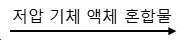

3.1.2.2 1# 2차 냉각제 흐름3.1.2.2 1 # Secondary Coolant Flow
1# 2차 콤프레서


3.1.2.3 2# 1차 냉각제 흐름3.1.2.3 2 # Primary Coolant Flow
2# 1차 콤프레서


3.1.2.4 2# 2차 냉각제 흐름3.1.2.4 2 # Secondary Coolant Flow
2# 2차 콤프레서


냉각수 흐름 원리도(냉각탑 또는 기타 냉각원)Coolant flow principle diagram (cooling tower or other cooling source)
냉각원(냉각탑 등) → 냉각수 → 냉각수관 → 수냉식 콘덴서 → 냉각수관 → 냉각원Cooling source (cooling tower, etc.) → Cooling water → Cooling water pipe → Water cooling condenser → Cooling water pipe → Cooling source
3.2.1.1 1# 공기 흐름3.2.1.1 1 # air flow
제습 공기 순환: 건조실 복귀 → 1차 공기 필터 → 2차 공기 필터 → 1# 축열기 열측 → 1# 1차 증발기 → 1# 2차 증발기 → 1# 축열기 냉측 → 1# 2차 콘덴서 → 1# 메인 팬 → 건조실Dehumidification air circulation: Dry chamber return → Primary air filter → Secondary air filter → 1 # heat accumulator side → 1 # primary evaporator → 1 # secondary evaporator → 1 # heat accumulator cold side → 1 # secondary condenser → 1 # main Pan → Drying Room
3.2.1.2 2# 공기 흐름3.2.1.2 2 # air flow
제습 공기 순환: 건조실 복귀 → 1차 공기 필터 → 2차 공기 필터 → 2# 축열기 냉각측 → 2# 1차 증발기 → 2# 2차 증발기 → 2# 축열기 승온측 → 2# 2차 콘덴서 → 2# 메인 팬 → 건조실Dehumidification air circulation: Dry chamber return → Primary air filter → Secondary air filter → 2 # regenerator cooling side → 2 # primary evaporator → 2 # secondary evaporator → 2 # regenerator elevated temperature → 2 # secondary condenser → 2 # Main fan → drying chamber
순환 공기 순환: 건조실 복귀 → 2# 1차 콘덴서 → 순환 팬 → 건조실Circulating air circulation: Drying chamber return → 2 # primary condenser → Circulating fan → Drying chamber
3.2.1.3 건조 매체(공기 등) 흐름3.2.1.3 Drying medium (air, etc.) flow
공기 유입


실시예 2Example 2
자동 항온 제습 장치는, 도 4 내지 5에 나타낸 바와 같이, 적어도 두 세트의 제습 히트 펌프 모듈을 포함하고, 상기 제습 히트 펌프 모듈은 두 개의 냉각제 모듈(제 1 냉각제 모듈 및 제 2 냉각제 모듈)과 한 개의 공기 모듈을 포함하고, 상기 냉각제 모듈의 각각은 1차 냉각 모듈 및 2차 냉각 모듈로 구성되고, 상기 1차 냉각 모듈은 공냉식 콘덴서(19), 1차 증발기(5) 및 콤프레서(14)를 포함하고, 상기 콤프레서(14)의 출구는 상기 공냉식 콘덴서(19)의 입구와 연결되고, 상기 공냉식 콘덴서(19)의 출구는 팽창 밸브를 통해 상기 1차 증발기(5)의 입구와 연결되고, 상기 1차 증발기(5)의 출구는 상기 콤프레서(14)와 연결된다. 2차 냉각 모듈은 2차 콘덴서(12), 2차 증발기(4) 및 콤프레서(14)를 포함하고, 상기 콤프레서(14)의 출구는 상기 2차 콘덴서(12)의 입구와 연결되고, 상기 2차 콘덴서(12)의 출구는 팽창 밸브(18)를 통해 상기 2차 증발기(4)의 입구와 연결되고, 상기 2차 증발기(4)의 출구는 상기 콤프레서(14)와 연결된다. 상기 공기 모듈의 흡기관은 공기 필터(2)를 통해 축열기(3)의 열측과 연결되고, 축열기(3)의 열측은 풍관을 통해 1차 증발기(5) 및 2차 증발기(4)와 연결되고, 상기 1차 증발기(5) 및 2차 증발기(4)는 풍관을 통해 축열기(3)의 냉측과 연결되고, 축열기(3)의 냉측은 풍관을 통해 상기 2차 콘덴서(12)와 연결되고, 2차 콘덴서(12)에서 배출되는 공기는 송풍구를 향해 유도되고, 상기 송풍구는 송풍기(11)에 설치된다. 상기 증발기(1차 증발기(5) 및 2차 증발기(4))와 콤프레서(14)의 사이에는 열교환기(13)가 연결된다. 상기 열교환기(13)와 상기 팽창 밸브(18)의 사이에는 필터(15)가 설치된다. 제습 히트 펌프 모듈 중 한 세트의 공냉식 콘덴서(19)에는 방열을 위한 순환 팬 세트(10)가 설치된다. 공냉식 콘덴서(19)에는 방열 팬(25)이 설치된다.The automatic constant temperature dehumidification device comprises at least two sets of dehumidification heat pump modules, as shown in FIGS. 4 to 5, wherein the dehumidification heat pump module comprises two coolant modules (a first coolant module and a second coolant module). Two air modules, each of the coolant modules comprising a primary cooling module and a secondary cooling module, wherein the primary cooling module comprises an air-cooled condenser 19, a primary evaporator 5 and a compressor 14. The outlet of the compressor 14 is connected to the inlet of the air-cooled condenser 19, the outlet of the air-cooled condenser 19 is connected to the inlet of the primary evaporator 5 through an expansion valve, The outlet of the primary evaporator 5 is connected to the compressor 14. The secondary cooling module comprises a
동작 원리는 다음과 같다.The principle of operation is as follows.
냉각제 흐름 원리도(냉각제는 무기화합물, 불화물 작동유체, 탄화수소화합물 또는 혼합 냉각제를 포함한다)Coolant flow principle diagram (coolant includes inorganic compound, fluoride working fluid, hydrocarbon compound or mixed coolant)
3.2.2.1 1# 1차 냉각제 흐름3.2.2.1 1 # Primary Coolant Flow
1# 1차 콤프레서


3.2.2.2 1# 2차 냉각제 흐름3.2.2.2 1 # Secondary Coolant Flow
1# 2차 콤프레서


3.2.2.3 2# 1차 냉각제 흐름3.2.2.3 2 # Primary Coolant Flow
2# 1차 콤프레서


3.2.2.4 2# 2차 냉각제 흐름3.2.2.4 2 # Secondary Coolant Flow
2# 2차 콤프레서


공냉식 콘덴서 공기 흐름 원리도(공기 냉각)Air-cooled condenser air flow principle diagram (air cooling)
실외 공기 → 공냉식 콘덴서 → 냉각 팬 → 실외 공기Outdoor air → air-cooled condenser → cooling fan → outdoor air
본 발명은 특정 작동 조건 범위에서 열평형 과정을 채택하고, 4개 또는 다수의 콤프레서 작업 공정 중 하나의(또는 두 개의) 콤프레서 및 콘덴서로 직접 열을 외부로 배출하고(냉각), 이에 따라 자동 항온 공정(40℃ ~ 60℃)을 실현한다. 재료량의 흡열 부하 및 시스템 방열 부하에 따라 자동으로 온도가 유지되어, 온도 제어 편차 ±2℃가 가능하며, 이는 슬러지 건조 온도 제어의 요구에 충분히 부합한다. 콤프레서 콘덴서 직접 외부 배출(냉각)을 채용하여, 밀폐식 건조 공정이 실현 가능하고, 슬러지 건조 공정 중 악취 배출이 없어, 탈취 장치를 필요로 하지 않는다. 순환 풍량과 제습 풍량을 분리 설계하여, 제습이 없는 순환 풍량의 설계는 습식 슬러지 건조 전기의 큰 풍량 요구를 만족시키고, 제습 풍량은 슬러지 건조 후기의 고온, 저습 요구를 만족시킨다. 슬러지 건조 단계의 상이한 풍량, 온도 및 습도에 대응한 특수한 설계는, 슬러지 건조 시간을 단축하고 슬러지 건조 분진 발생을 방지할 수 있다. 순환 팬, 메인 팬(제습 팬)의 외부 설치 구조는 슬러지 건조 모델 구조의 설계 요구를 충족시키는 동시에 제습 히트 펌프의 메인 구조체의 부피를 감소시킬 수 있다. 당해 장치는 구조가 간단하고, 점유 면적이 작으며, 유지보수 공간이 작고, 장치는 단지 한 방향의 유지보수 공간만을 필요로 하여, 슬러지 건조기의 모듈식 구조 요구에 충분히 적합할 수 있다. 기존의 공기 환열 기술 및 이단 냉각 기술을 이용하는 제습 히트 펌프(3중 효과 제습 히트 펌프)에 기반하여, 4개의(또는 다수의) 콤프레서를 설치함으로써, 슬러지 건조 제습 히트 펌프의 전체 제습 성능이 향상된다.The present invention employs a thermal equilibrium process over a range of operating conditions, directs heat to the outside (cooling) with one (or two) compressors and condensers of four or multiple compressor operating processes, and thus automatically constant temperature. The process (40 degreeC-60 degreeC) is implement | achieved. The temperature is automatically maintained depending on the endothermic load of the material amount and the system heat dissipation load, allowing a temperature control deviation of ± 2 ° C, which is sufficient to meet the needs of sludge drying temperature control. By adopting a compressor capacitor direct external discharge (cooling), a hermetic drying process can be realized, there is no odor emission during the sludge drying process, and no deodorizing device is required. By separately designing the circulation air flow and the dehumidification air flow, the design of the circulation air flow without dehumidification satisfies the large air flow requirements of the wet sludge drying electric machine, and the dehumidification air flow satisfies the high temperature and low humidity demands of the late sludge drying. The special design corresponding to the different air volume, temperature and humidity of the sludge drying step can shorten the sludge drying time and prevent sludge dry dust generation. The external installation structure of the circulation fan, the main fan (dehumidification fan) can reduce the volume of the main structure of the dehumidification heat pump while meeting the design requirements of the sludge drying model structure. The apparatus is simple in structure, small in occupied area, small in maintenance space, and the apparatus needs only one direction of maintenance space, and can be sufficiently adapted to the modular structure requirements of the sludge dryer. Based on the existing dehumidification heat pumps and the two-stage cooling technology (three-effect dehumidification heat pump), by installing four (or multiple) compressors, the overall dehumidification performance of the sludge dry dehumidification heat pump is improved. .
단열 케이싱(21)에는 작업 공정 중 각 장치의 운행 상황을 모니터하기 위한 계기판이 설치된다. 계기판은 건조실 내 온도, 습도, 출구 공기 온도, 전원 표시, 콤프레서 운행, 팬 운행, 보조 팬 운행, 표시 설정 운행, 정지 버튼, 팬 수동 자동 버튼, 고장 표시 및 리셋 등의 파라미터를 디스플레이할 수 있다. 브라켓 및 케이싱 내에 제어 박스가 설치되고, 제어 박스 내에는 콤프레서, 팬 강전 제어 장치와 제습, 냉각, 가열, 환기 등을 포함하는 제어 기능 모듈이 설치될 수 있다.The insulation casing 21 is provided with an instrument panel for monitoring the operating status of each device during the work process. The instrument panel can display parameters such as temperature in the drying room, humidity, outlet air temperature, power indication, compressor operation, fan operation, auxiliary fan operation, display setting operation, stop button, automatic fan manual button, fault indication and reset. A control box may be installed in the bracket and the casing, and a control function module including a compressor, a fan power control device, and dehumidification, cooling, heating, and ventilation may be installed in the control box.
상기 축열기(3)는 플레이트 핀(plate-fin) 타입 축열기, 즉, 플레이트 핀형 열교환기이다. 플레이트 핀 타입 축열기는 칸막이판, 핀(fin), 시일(seal), 배플(baffle)로 구성되고, 인접한 칸막이판의 사이에 핀과 배플을 배치하여 샌드위치 구조를 형성하고, 샌드위치 구조는 적층하고 브레이징하여 전체를 하나의 번들로 형성하고, 필요한 엔드캡을 배치하여 지지한다. 핀은 직선형 핀, 톱니형 핀, 다공(多孔) 핀, 물결모양 핀 등이 될 수 있다.The heat accumulator 3 is a plate-fin type heat accumulator, that is, a plate fin heat exchanger. Plate fin type heat accumulator is composed of partition plate, fin, seal and baffle, and sandwiches fin and baffle between adjacent partition plates to form sandwich structure, sandwich structure is laminated Braze to form the entire bundle into one bundle and place and support the required end caps. The pins may be straight pins, toothed pins, porous pins, wavy pins, or the like.
증발기(2차 증발기(4) 및 1차 증발기(5))는 핀 튜브(fin tube) 증발기이다. 핀 튜브 증발기는 기본관과 핀으로 구성되고, 핀은 기본관에 장착된다. 기본관은 동관 또는 내부 나사산 동관을 이용한다. 핀은 알루미늄 또는 구리로 된 물결모양 핀이고, 천창(天窓)식 또는 물결모양 천창식이다. 콘덴서는 핀 튜브식 열교환기이다. 핀 튜브식 열교환기는 기본관과 핀으로 구성되고, 핀은 기본관에 장착된다. 기본관은 기본관은 동관 또는 내부 나사산 동관을 이용한다. 핀은 알루미늄 또는 구리로 된 물결모양 핀이고, 천창(天窓)식 또는 물결모양 천창식이다. 단열 하우징 내의 브라켓은 강판 성형, 판금 가공 또는 알루미늄 합금 성형으로 제조되어야 한다. 케이싱은 단열성을 갖는 복합 단열판을 구비하고, 단열층의 두께는 25mm 이상이고, 또한 복합 단열판의 내층판은 내식성이 우수한 아연 도금 강판, 알루미늄판 또는 스테인리스 스틸판을 구비할 수 있다. 칸막이판(23)은 내식성이 우수한 아연 도금 강판 또는 알루미늄판을 이용하여 제작될 수 있다. 물받이는 내식 알루미늄판 또는 스테인리스 스틸판을 이용할 수 있다. 응결수 배출관은 아연 도금 강관 또는 스테인리스 스틸관을 이용할 수 있고, 또한 엘보우 파이프를 가질 수도 있다. 수냉식 콘덴서는 원통다관식(shell-and-tube), 용접형 판형(brazed plate), 케이싱 타입일 수 있고, 그 유수 경로에서 내식성을 고려해야 한다.The evaporators (secondary evaporator 4 and primary evaporator 5) are fin tube evaporators. Fin tube evaporator consists of a base tube and a fin, the fin is mounted to the base tube. The base tube uses copper tube or internal threaded copper tube. The pin is a corrugated pin made of aluminum or copper, and is a skylight or a wavy skylight. The condenser is a fin tube type heat exchanger. Finned tube heat exchanger consists of a base tube and a fin, the fin is mounted to the base tube. The base tube is a copper tube or an internal threaded copper tube. The pin is a corrugated pin made of aluminum or copper, and is a skylight or a wavy skylight. The brackets in the insulating housing should be manufactured by sheet metal forming, sheet metal processing or aluminum alloy molding. The casing includes a composite heat insulating plate having heat insulating property, and the heat insulating layer has a thickness of 25 mm or more, and the inner layer plate of the composite heat insulating plate may be provided with a galvanized steel sheet, an aluminum plate, or a stainless steel plate excellent in corrosion resistance. The partition plate 23 may be manufactured using a galvanized steel sheet or an aluminum plate having excellent corrosion resistance. The drip tray may use a corrosion-resistant aluminum plate or a stainless steel plate. The condensate discharge pipe may use a galvanized steel pipe or a stainless steel pipe, and may also have an elbow pipe. Water-cooled condensers can be shell-and-tube, welded plate, casing type, and corrosion resistance must be taken into account in the flow path.
이상 상술한 바는 본 발명의 바람직한 실시예에 불과하고, 본 발명의 범위는 이에 한정되지 않으며, 즉, 본 발명의 청구범위 및 발명의 설명의 내용에 따라 이루어진 단순하고 동등한 변경 및 수정은, 모두 여전히 본 발명의 범위 내에 속한다.The foregoing is merely a preferred embodiment of the present invention, and the scope of the present invention is not limited thereto, that is, the simple and equivalent changes and modifications made in accordance with the contents of the claims and the description of the present invention are all It is still within the scope of the present invention.
Claims (10)
적어도 두 세트의 제습 히트 펌프 모듈을 포함하고,
상기 제습 히트 펌프 모듈은 두 개의 냉각제 모듈 및 한 개의 공기 모듈을 포함하고,
상기 냉각제 모듈은 1차 냉각 모듈 및 2차 냉각 모듈을 포함하고,
상기 1차 냉각 모듈 및 상기 2차 냉각 모듈은 콘덴서, 증발기 및 콤프레서를 포함하고, 상기 콤프레서의 출구는 상기 콘덴서의 입구와 연결되고, 상기 콘덴서의 출구는 팽창 밸브를 통해 상기 증발기의 입구와 연결되고, 상기 증발기의 출구는 상기 콤프레서와 연결되고,
상기 공기 모듈의 흡기관은 축열기의 열측과 연결되고, 상기 축열기의 열측은 풍관을 통해 상기 증발기와 연결되고, 상기 증발기는 풍관을 통해 상기 축열기의 냉측과 연결되고, 상기 축열기의 냉측은 풍관을 통해 상기 콘덴서 중 하나와 연결되는 것을 특징으로 하는 자동 항온 제습 장치.Automatic constant temperature dehumidifier,
At least two sets of dehumidification heat pump modules,
The dehumidification heat pump module includes two coolant modules and one air module,
The coolant module includes a primary cooling module and a secondary cooling module,
The primary cooling module and the secondary cooling module include a condenser, an evaporator and a compressor, the outlet of the compressor is connected to the inlet of the condenser, the outlet of the condenser is connected to the inlet of the evaporator through an expansion valve. The outlet of the evaporator is connected to the compressor,
The intake pipe of the air module is connected to the heat side of the heat accumulator, the heat side of the heat accumulator is connected to the evaporator through a wind pipe, the evaporator is connected to the cold side of the heat accumulator through a wind pipe, and the cold side of the heat accumulator is The side is connected to one of the condenser through a wind pipe, the automatic constant temperature dehumidifier.
상기 1차 냉각 모듈의 콘덴서는 수냉식 콘덴서인 것을 특징으로 하는 자동 항온 제습 장치.The method of claim 1,
Condenser of the primary cooling module is an automatic constant temperature dehumidifier characterized in that the water-cooled condenser.
상기 1차 냉각 모듈의 콘덴서는 공냉식 콘덴서인 것을 특징으로 하는 자동 항온 제습 장치.The method of claim 1,
Condenser of the primary cooling module is an automatic constant temperature dehumidifier characterized in that the air-cooled condenser.
상기 제 2 냉각제 모듈의 1차 냉각 모듈의 콘덴서에는 공냉식 방열에 이용되는 팬 세트가 설치되는 것을 특징으로 하는 자동 항온 제습 장치.The method of claim 2 or 3,
The condenser of the primary cooling module of the second coolant module is an automatic constant temperature dehumidifier, characterized in that the fan set for air-cooled heat dissipation is installed.
상기 증발기와 상기 콤프레서의 사이에는 열교환기가 연결되는 것을 특징으로 하는 자동 항온 제습 장치.The method of claim 4, wherein
Automatic constant temperature dehumidifier characterized in that the heat exchanger is connected between the evaporator and the compressor.
상기 열교환기와 상기 팽창 밸브의 사이에는 필터가 설치되는 것을 특징으로 하는 자동 항온 제습 장치.The method of claim 5,
An automatic constant temperature dehumidifier, characterized in that a filter is installed between the heat exchanger and the expansion valve.
두 세트의 상기 제습 히트 펌프 모듈은 단열 케이싱 내에 설치되어 각각 단열 케이싱의 양측에 배치되고, 상기 단열 케이싱 내에는 칸막이판에 의해 서로 분리된 혼합 공기 챔버와 건조실이 설치되는 것을 특징으로 하는 자동 항온 제습 장치.The method of claim 6,
Two sets of the dehumidifying heat pump modules are installed in the insulating casing and are respectively disposed on both sides of the insulating casing, and the mixed air chamber and the drying chamber separated from each other by the partition plate are installed in the insulating casing. Device.
두 개의 상기 축열기는 상기 단열 케이싱의 중앙부에 설치되고, 두 개의 상기 축열기의 사이에 혼합 공기 챔버가 형성되는 것을 특징으로 하는 자동 항온 제습 장치.The method of claim 7, wherein
Two of said heat accumulator are installed in the center part of the said heat insulation casing, The automatic constant temperature dehumidifier characterized in that the mixed air chamber is formed between two said heat accumulators.
상기 혼합 공기 챔버의 하부 양측에는 각각 1차 증발기 및 2차 증발기가 설치되는 것을 특징으로 하는 자동 항온 제습 장치.The method of claim 8,
An automatic constant temperature dehumidifier, characterized in that the primary evaporator and the secondary evaporator are respectively installed on both lower sides of the mixed air chamber.
상기 단열 케이싱에는 상기 제습 히트 펌프 모듈에 대응하는 공기 필터가 각각 설치되고, 상기 공기 필터 상에는 상부 필터가 설치되는 것을 특징으로 하는 자동 항온 제습 장치.The method of claim 9,
And an air filter corresponding to the dehumidifying heat pump module, respectively, and the upper filter is installed on the air filter.
Applications Claiming Priority (3)
| Application Number | Priority Date | Filing Date | Title |
|---|---|---|---|
| CN201611252091.3A CN106766375B (en) | 2016-12-29 | 2016-12-29 | Automatic thermostatic dehumidifying device |
| CN201611252091.3 | 2016-12-29 | ||
| PCT/CN2017/118407 WO2018121486A1 (en) | 2016-12-29 | 2017-12-25 | Automatic constant-temperature dehumidification device |
Publications (2)
| Publication Number | Publication Date |
|---|---|
| KR20190079655A KR20190079655A (en) | 2019-07-05 |
| KR102055644B1 true KR102055644B1 (en) | 2019-12-16 |
Family
ID=58928028
Family Applications (1)
| Application Number | Title | Priority Date | Filing Date |
|---|---|---|---|
| KR1020197015874A Active KR102055644B1 (en) | 2016-12-29 | 2017-12-25 | Automatic constant temperature dehumidifier |
Country Status (4)
| Country | Link |
|---|---|
| US (1) | US11479493B2 (en) |
| KR (1) | KR102055644B1 (en) |
| CN (1) | CN106766375B (en) |
| WO (1) | WO2018121486A1 (en) |
Cited By (1)
| Publication number | Priority date | Publication date | Assignee | Title |
|---|---|---|---|---|
| KR102190564B1 (en) | 2020-07-08 | 2020-12-15 | 배순석 | Constant temperature dehumidification and drying apparatus |
Families Citing this family (19)
| Publication number | Priority date | Publication date | Assignee | Title |
|---|---|---|---|---|
| CN106766375B (en) * | 2016-12-29 | 2019-07-12 | 石曾矿 | Automatic thermostatic dehumidifying device |
| CN109081546A (en) * | 2017-06-13 | 2018-12-25 | 光大水务科技发展(南京)有限公司 | Sludge air energy desiccation apparatus |
| CN108679996B (en) * | 2018-04-23 | 2024-05-14 | 广州晟启能源设备有限公司 | Closed heat pump condensation heat recovery drying system |
| CN108955225A (en) * | 2018-08-21 | 2018-12-07 | 广州晟启能源设备有限公司 | A kind of air-cooled dehumidifying heat pump that can be realized temperature and adjust in due course |
| CN108759445A (en) * | 2018-08-23 | 2018-11-06 | 广州晟启能源设备有限公司 | A kind of air-cooled dehumidifying heat pump |
| CN109293210B (en) * | 2018-10-07 | 2021-08-10 | 浙江诺曼环保工程技术有限公司 | Intelligent low-energy-consumption low-temperature sludge drying method |
| CN109282587A (en) * | 2018-10-10 | 2019-01-29 | 青岛大学 | A heat pump dryer with symmetrical parallel arrangement of cooling and dehumidifying evaporators |
| CN110240377B (en) * | 2019-06-28 | 2021-11-09 | 西安建筑科技大学 | Fluidized bed sludge drying equipment and method based on freezing wall breaking and hot air drying |
| CN112361649A (en) * | 2020-12-02 | 2021-02-12 | 四川蜀冷冷暖设备有限公司 | Multifunctional direct-heating constant-temperature dehumidifying and drying heat pump all-in-one machine |
| KR102509454B1 (en) | 2021-04-14 | 2023-03-14 | 주식회사 은하에어테크 | Air dryer and compressed air drying method thereof |
| KR102509455B1 (en) * | 2021-04-14 | 2023-03-14 | 주식회사 은하에어테크 | Air drying system and compressed air drying method thereof |
| CN113739556B (en) * | 2021-07-21 | 2023-01-10 | 广东申菱环境系统股份有限公司 | A heat pump drying unit and its control method |
| CN113959216B (en) * | 2021-10-15 | 2023-02-28 | 青岛海尔空调电子有限公司 | Method and device for dehumidification, electronic equipment and storage medium |
| KR102371758B1 (en) * | 2021-11-02 | 2022-03-04 | 오상건 | Constant Temperature Chamber |
| CN114279200B (en) * | 2021-12-29 | 2023-09-15 | 张家港市锦越机械有限公司 | Building block type dryer |
| CN114646190A (en) * | 2022-04-17 | 2022-06-21 | 河南三张节能环保工程有限公司 | Raw material drying method and device for industrial and agricultural products |
| CN114933404A (en) * | 2022-06-02 | 2022-08-23 | 江苏通用环保集团有限公司 | Multistage energy-saving closed dehumidification heat pump system |
| CN115845576A (en) * | 2022-11-28 | 2023-03-28 | 南京霍普斯科技有限公司 | Low-temperature condensation water removing device |
| CN116037625B (en) * | 2022-12-26 | 2024-08-09 | 江苏辛普森新能源有限公司 | Heat pump type kitchen waste treatment equipment |
Citations (1)
| Publication number | Priority date | Publication date | Assignee | Title |
|---|---|---|---|---|
| JP2015210005A (en) | 2014-04-25 | 2015-11-24 | 株式会社前川製作所 | Dehumidifying air conditioning method and apparatus |
Family Cites Families (9)
| Publication number | Priority date | Publication date | Assignee | Title |
|---|---|---|---|---|
| US3745782A (en) * | 1972-03-02 | 1973-07-17 | Carrier Corp | Sludge separation systems employing refrigeration means |
| CN201242340Y (en) * | 2008-04-30 | 2009-05-20 | 石曾矿 | Novel heat pump dehumidification drier |
| CN201811551U (en) * | 2010-09-29 | 2011-04-27 | 石曾矿 | Novel multifunctional dehumidifying dryer |
| CN102003759B (en) * | 2010-12-09 | 2013-02-27 | 上海交通大学 | Regenerative evaporative cooling air conditioner |
| CN103040086B (en) * | 2012-12-28 | 2015-04-22 | 广州晟启能源设备有限公司 | Dehumidifying heat pump unit and tobacco-dehumidifying heat pump baking device |
| CN104098240B (en) * | 2014-08-04 | 2015-10-21 | 中国计量学院 | Sewage sludge treatment plant |
| CN204286023U (en) * | 2014-11-17 | 2015-04-22 | 林建东 | One is applicable to round-the-clock heat pump dryer |
| CN206670121U (en) * | 2016-12-29 | 2017-11-24 | 石曾矿 | Automatic thermostatic dehumidifying device |
| CN106766375B (en) * | 2016-12-29 | 2019-07-12 | 石曾矿 | Automatic thermostatic dehumidifying device |
-
2016
- 2016-12-29 CN CN201611252091.3A patent/CN106766375B/en active Active
-
2017
- 2017-12-25 US US16/465,154 patent/US11479493B2/en active Active
- 2017-12-25 KR KR1020197015874A patent/KR102055644B1/en active Active
- 2017-12-25 WO PCT/CN2017/118407 patent/WO2018121486A1/en not_active Ceased
Patent Citations (1)
| Publication number | Priority date | Publication date | Assignee | Title |
|---|---|---|---|---|
| JP2015210005A (en) | 2014-04-25 | 2015-11-24 | 株式会社前川製作所 | Dehumidifying air conditioning method and apparatus |
Cited By (2)
| Publication number | Priority date | Publication date | Assignee | Title |
|---|---|---|---|---|
| KR102190564B1 (en) | 2020-07-08 | 2020-12-15 | 배순석 | Constant temperature dehumidification and drying apparatus |
| KR20220006436A (en) | 2020-07-08 | 2022-01-17 | 배순석 | Constant temperature dehumidification and drying apparatus |
Also Published As
| Publication number | Publication date |
|---|---|
| CN106766375A (en) | 2017-05-31 |
| CN106766375B (en) | 2019-07-12 |
| US20210284561A1 (en) | 2021-09-16 |
| KR20190079655A (en) | 2019-07-05 |
| WO2018121486A1 (en) | 2018-07-05 |
| US11479493B2 (en) | 2022-10-25 |
Similar Documents
| Publication | Publication Date | Title |
|---|---|---|
| KR102098103B1 (en) | Temperature-controlled quad-effect dehumidification drying system | |
| CN106766375B (en) | Automatic thermostatic dehumidifying device | |
| CN104034145B (en) | Heat pump dehumidifier | |
| CN207230813U (en) | A kind of integrated air conditioner and cabinet | |
| CN103491733A (en) | Sealing equipment cabinet with active/passive combination cooling system | |
| CN218514733U (en) | Air conditioner | |
| CN107023905A (en) | Radiator and air conditioner | |
| CN220541247U (en) | Dehumidifier | |
| CN220582587U (en) | Dehumidifier | |
| CN108679996B (en) | Closed heat pump condensation heat recovery drying system | |
| CN111829075A (en) | A thin air conditioner indoor heat exchange system | |
| CN219913267U (en) | window air conditioner | |
| CN118310107A (en) | Integral heat pump unit | |
| CN201407766Y (en) | water-cooled cooler | |
| CN210801409U (en) | A water-cooled temperature-adjusting dehumidifier | |
| CN212463891U (en) | A cabinet and data room cooling system | |
| CN115704582A (en) | Automatically controlled box, air condensing units and air conditioner | |
| CN209805651U (en) | Frequency converter | |
| KR100896805B1 (en) | Steam Air Conditioner with Constant Temperature and Humidity | |
| CN206670121U (en) | Automatic thermostatic dehumidifying device | |
| CN207471729U (en) | Modular air conditioner | |
| CN221881575U (en) | Liquid distributor for condenser, condenser and air-conditioning type range hood | |
| CN219305307U (en) | Hot air cooling device for high-voltage frequency converter and power electronic equipment | |
| CN118368875B (en) | A dual-cold-source energy-saving thermal management device for cabinets | |
| CN219068744U (en) | Heat abstractor for be used for industrial automation switch board |
Legal Events
| Date | Code | Title | Description |
|---|---|---|---|
| A201 | Request for examination | ||
| P11-X000 | Amendment of application requested |
St.27 status event code: A-2-2-P10-P11-nap-X000 |
|
| P13-X000 | Application amended |
St.27 status event code: A-2-2-P10-P13-nap-X000 |
|
| PA0105 | International application |
St.27 status event code: A-0-1-A10-A15-nap-PA0105 |
|
| PA0201 | Request for examination |
St.27 status event code: A-1-2-D10-D11-exm-PA0201 |
|
| PG1501 | Laying open of application |
St.27 status event code: A-1-1-Q10-Q12-nap-PG1501 |
|
| A302 | Request for accelerated examination | ||
| PA0302 | Request for accelerated examination |
St.27 status event code: A-1-2-D10-D17-exm-PA0302 St.27 status event code: A-1-2-D10-D16-exm-PA0302 |
|
| E701 | Decision to grant or registration of patent right | ||
| PE0701 | Decision of registration |
St.27 status event code: A-1-2-D10-D22-exm-PE0701 |
|
| GRNT | Written decision to grant | ||
| PR0701 | Registration of establishment |
St.27 status event code: A-2-4-F10-F11-exm-PR0701 |
|
| PR1002 | Payment of registration fee |
St.27 status event code: A-2-2-U10-U12-oth-PR1002 Fee payment year number: 1 |
|
| PG1601 | Publication of registration |
St.27 status event code: A-4-4-Q10-Q13-nap-PG1601 |
|
| S17-X000 | Non-exclusive voluntary license recorded |
St.27 status event code: A-4-4-S10-S17-lic-X000 |
|
| P22-X000 | Classification modified |
St.27 status event code: A-4-4-P10-P22-nap-X000 |
|
| PR1001 | Payment of annual fee |
St.27 status event code: A-4-4-U10-U11-oth-PR1001 Fee payment year number: 4 |
|
| PR1001 | Payment of annual fee |
St.27 status event code: A-4-4-U10-U11-oth-PR1001 Fee payment year number: 5 |
|
| PR1001 | Payment of annual fee |
St.27 status event code: A-4-4-U10-U11-oth-PR1001 Fee payment year number: 6 |
|
| PR1001 | Payment of annual fee |
St.27 status event code: A-4-4-U10-U11-oth-PR1001 Fee payment year number: 7 |
|
| U11 | Full renewal or maintenance fee paid |
Free format text: ST27 STATUS EVENT CODE: A-4-4-U10-U11-OTH-PR1001 (AS PROVIDED BY THE NATIONAL OFFICE) Year of fee payment: 7 |
|
| P22-X000 | Classification modified |
St.27 status event code: A-4-4-P10-P22-nap-X000 |