KR101753315B1 - Assembling structure of door frame - Google Patents
Assembling structure of door frame Download PDFInfo
- Publication number
- KR101753315B1 KR101753315B1 KR1020150059795A KR20150059795A KR101753315B1 KR 101753315 B1 KR101753315 B1 KR 101753315B1 KR 1020150059795 A KR1020150059795 A KR 1020150059795A KR 20150059795 A KR20150059795 A KR 20150059795A KR 101753315 B1 KR101753315 B1 KR 101753315B1
- Authority
- KR
- South Korea
- Prior art keywords
- roller unit
- unit housing
- vertical
- door frame
- roller
- Prior art date
- Legal status (The legal status is an assumption and is not a legal conclusion. Google has not performed a legal analysis and makes no representation as to the accuracy of the status listed.)
- Expired - Fee Related
Links
Images




Classifications
-
- E—FIXED CONSTRUCTIONS
- E06—DOORS, WINDOWS, SHUTTERS, OR ROLLER BLINDS IN GENERAL; LADDERS
- E06B—FIXED OR MOVABLE CLOSURES FOR OPENINGS IN BUILDINGS, VEHICLES, FENCES OR LIKE ENCLOSURES IN GENERAL, e.g. DOORS, WINDOWS, BLINDS, GATES
- E06B3/00—Window sashes, door leaves, or like elements for closing wall or like openings; Layout of fixed or moving closures, e.g. windows in wall or like openings; Features of rigidly-mounted outer frames relating to the mounting of wing frames
- E06B3/70—Door leaves
-
- E—FIXED CONSTRUCTIONS
- E05—LOCKS; KEYS; WINDOW OR DOOR FITTINGS; SAFES
- E05D—HINGES OR SUSPENSION DEVICES FOR DOORS, WINDOWS OR WINGS
- E05D15/00—Suspension arrangements for wings
- E05D15/06—Suspension arrangements for wings for wings sliding horizontally more or less in their own plane
- E05D15/0621—Details, e.g. suspension or supporting guides
- E05D15/066—Details, e.g. suspension or supporting guides for wings supported at the bottom
-
- E—FIXED CONSTRUCTIONS
- E05—LOCKS; KEYS; WINDOW OR DOOR FITTINGS; SAFES
- E05F—DEVICES FOR MOVING WINGS INTO OPEN OR CLOSED POSITION; CHECKS FOR WINGS; WING FITTINGS NOT OTHERWISE PROVIDED FOR, CONCERNED WITH THE FUNCTIONING OF THE WING
- E05F11/00—Man-operated mechanisms for operating wings, including those which also operate the fastening
- E05F11/54—Man-operated mechanisms for operating wings, including those which also operate the fastening for doors
-
- E—FIXED CONSTRUCTIONS
- E06—DOORS, WINDOWS, SHUTTERS, OR ROLLER BLINDS IN GENERAL; LADDERS
- E06B—FIXED OR MOVABLE CLOSURES FOR OPENINGS IN BUILDINGS, VEHICLES, FENCES OR LIKE ENCLOSURES IN GENERAL, e.g. DOORS, WINDOWS, BLINDS, GATES
- E06B3/00—Window sashes, door leaves, or like elements for closing wall or like openings; Layout of fixed or moving closures, e.g. windows in wall or like openings; Features of rigidly-mounted outer frames relating to the mounting of wing frames
- E06B3/32—Arrangements of wings characterised by the manner of movement; Arrangements of movable wings in openings; Features of wings or frames relating solely to the manner of movement of the wing
- E06B3/34—Arrangements of wings characterised by the manner of movement; Arrangements of movable wings in openings; Features of wings or frames relating solely to the manner of movement of the wing with only one kind of movement
- E06B3/42—Sliding wings; Details of frames with respect to guiding
- E06B3/46—Horizontally-sliding wings
- E06B3/4636—Horizontally-sliding wings for doors
-
- E—FIXED CONSTRUCTIONS
- E06—DOORS, WINDOWS, SHUTTERS, OR ROLLER BLINDS IN GENERAL; LADDERS
- E06B—FIXED OR MOVABLE CLOSURES FOR OPENINGS IN BUILDINGS, VEHICLES, FENCES OR LIKE ENCLOSURES IN GENERAL, e.g. DOORS, WINDOWS, BLINDS, GATES
- E06B3/00—Window sashes, door leaves, or like elements for closing wall or like openings; Layout of fixed or moving closures, e.g. windows in wall or like openings; Features of rigidly-mounted outer frames relating to the mounting of wing frames
- E06B3/96—Corner joints or edge joints for windows, doors, or the like frames or wings
-
- E—FIXED CONSTRUCTIONS
- E05—LOCKS; KEYS; WINDOW OR DOOR FITTINGS; SAFES
- E05Y—INDEXING SCHEME ASSOCIATED WITH SUBCLASSES E05D AND E05F, RELATING TO CONSTRUCTION ELEMENTS, ELECTRIC CONTROL, POWER SUPPLY, POWER SIGNAL OR TRANSMISSION, USER INTERFACES, MOUNTING OR COUPLING, DETAILS, ACCESSORIES, AUXILIARY OPERATIONS NOT OTHERWISE PROVIDED FOR, APPLICATION THEREOF
- E05Y2201/00—Constructional elements; Accessories therefor
- E05Y2201/60—Suspension or transmission members; Accessories therefor
- E05Y2201/622—Suspension or transmission members elements
- E05Y2201/688—Rollers
-
- E—FIXED CONSTRUCTIONS
- E05—LOCKS; KEYS; WINDOW OR DOOR FITTINGS; SAFES
- E05Y—INDEXING SCHEME ASSOCIATED WITH SUBCLASSES E05D AND E05F, RELATING TO CONSTRUCTION ELEMENTS, ELECTRIC CONTROL, POWER SUPPLY, POWER SIGNAL OR TRANSMISSION, USER INTERFACES, MOUNTING OR COUPLING, DETAILS, ACCESSORIES, AUXILIARY OPERATIONS NOT OTHERWISE PROVIDED FOR, APPLICATION THEREOF
- E05Y2600/00—Mounting or coupling arrangements for elements provided for in this subclass
- E05Y2600/40—Mounting location; Visibility of the elements
- E05Y2600/46—Mounting location; Visibility of the elements in or on the wing
Landscapes
- Engineering & Computer Science (AREA)
- Civil Engineering (AREA)
- Structural Engineering (AREA)
- Mechanical Engineering (AREA)
- Support Devices For Sliding Doors (AREA)
Abstract
본 발명은 문틀의 양측 하부에 설치되는 구조가 다른 다양한 롤러유닛을 공용으로 제한 없이 모두 적용하여 설치할 수 있도록 한 문틀 조립구조에 관한 것으로, 중공부(110)와 제1연결부재(120)가 끼워져 나사체결로 고정되는 제1연결부재홈(130)을 구비하는 양측 수직바(100), 양측 수직바(100)의 하부에 배치되어 제1연결부재(130)에 끼워져 고정볼트(210)로 고정되는 제2연결부재(220)를 구비하는 수평바(200)를 포함하는 문틀(10)에 있어서, 수직바(100)의 외벽과 내벽의 하부 중앙에 중공부(110)와 통하도록 수직으로 각각 개방되는 수직장공(140); 수직바(100)의 양측 수직장공(140) 사이로 압입되어 롤러유닛(20)(30)(40)들 중 어느 하나를 선택적으로 수용하는 하부와 내측이 개방된 수용부(310)와, 외측 수직장공(140)으로 끼워지는 삽입부(320)의 외측홈(321)에 형성되어 롤러유닛(20)(30)(40)의 높이조절볼트(21)(31)(41)와 마주하는 하나 이상의 높이조절공(330)을 구비하는 롤러유닛하우징(300); 롤러유닛하우징(300)의 수용부(310)와 통하도록 수평바(200)의 하부 내측에 형성되는 연결부(230)를 더 포함하여 구성된다.The present invention relates to a door frame assembly structure in which various roller units having different structures provided on both sides of a door frame can be applied without limitation and all of them can be installed. The hollow frame assembly 110 and the first connecting member 120 are fitted Side vertical bar 100 having a first connecting member groove 130 fixed by a screw connection and a second connecting member groove 130 fixed to the first connecting member 130 by fixing bolts 210 The vertical bar 100 is provided with a horizontal bar 200 having a first connecting member 220 and a second connecting member 220. The vertical bar 100 is vertically connected to the lower center of the outer wall and the inner wall of the vertical bar 100, An open vertical slot 140; A receiving portion 310 which is press-fitted between both vertical slots 140 of the vertical bar 100 to selectively receive any one of the roller units 20, 30 and 40, (41) of the roller units (20), (30), and (40) formed in the outer groove (321) of the insertion portion (320) inserted into the long hole (140) A roller unit housing 300 having a height adjusting hole 330; And a connecting part 230 formed inside the lower part of the horizontal bar 200 to communicate with the receiving part 310 of the roller unit housing 300.
Description
본 발명은 문틀 조립구조에 관한 것으로, 더 상세하게는 롤러유닛하우징을 이용하여 문틀의 양측 하부에 설치되는 구조가 다른 다양한 롤러유닛을 공용으로 설치할 수 있도록 하고, 이를 통해 문틀의 통일된 규격화와 공용화가 가능하고 구조에 관계없이 여러 가지 구조가 다른 롤러유닛을 현장 여건에 맞게 쉽고 간단하게 제한 없이 모두 적용하여 사용할 수 있도록 한 문틀 조립구조에 관한 것이다.BACKGROUND OF THE INVENTION 1. Field of the Invention The present invention relates to a door frame assembly structure, and more particularly, to a door frame assembly structure in which various roller units having different structures, which are installed at both lower sides of a door frame, can be commonly installed using a roller unit housing, The present invention relates to a door frame assembly structure in which various roller units can be easily and easily adapted to the field conditions without any limitations.
일반적으로 실내와 실외를 출입할 수 있도록 출입문이 설치되어 있으며, 그 출입문은 문틀에 의해서 고정되어 있다.Generally, doors and doors are installed for indoor and outdoor access, and the door is fixed by a door frame.
상기 문틀은 한 쌍의 수평바와 한 쌍의 수직바로 이루어져 있으며, 상기 수평바와 수직바의 단부는 별도의 연결구에 의해서 연결 고정되는 것이다.The door frame is composed of a pair of horizontal bars and a pair of vertical bars, and the horizontal bars and the ends of the vertical bars are connected and fixed by separate connectors.
상기 문틀은 출입문을 견고히 고정 지지하기 위한 것으로서, 수평바와 수직의 연결부 즉, 단부의 결합력이 견고히 유지되어야 한다.The door frame is for firmly supporting the door, and the connecting force perpendicular to the horizontal bar, that is, the end, must be firmly maintained.
그리고 문틀의 양측 하부에는 하부레일을 따라 이동되는 롤러유닛이 각각 설치된다. 이때, 상기 양측의 롤러유닛은 문틀이 원활하게 이동되도록 안내하는 역할을 수행한다. 이러한 문틀 조립구조에 대한 상세한 내용은 하기 특허문헌인 국내 공개특허 제10-2012-0115879호에 기재되어 있다.And roller units that are moved along the lower rails are installed at lower portions of both sides of the door frame. At this time, the roller units on both sides serve to guide the door frame to move smoothly. Details of such a door frame assembly structure are disclosed in Japanese Patent Laid-Open No. 10-2012-0115879.
그러나, 종래에는 양측 수직바의 하부에 개방부를 형성하여 롤러유닛을 장착하였기 때문에, 구조가 다른 다양한 롤러유닛을 공용으로 설치할 수 없는 문제점이 있었으며, 이로 인하여 문틀의 통일된 규격화와 공용화가 불가능하고 구조에 따라 여러 가지 롤러유닛을 현장 여건에 따라 제한적으로 사용할 수밖에 없는 불편한 문제점이 있었다.However, conventionally, since the roller unit is mounted on the lower portion of the vertical bars on both sides, various roller units having different structures can not be commonly installed. As a result, it is impossible to standardize and commonize the door frames. There is a problem in that it is inconvenient that various roller units can only be used in a limited manner according to the field conditions.
또한 종래에는 양측 수직바의 하부와 하부레일 사이에 틈새가 그대로 노출되기 때문에 방음 및 방풍효과를 기대할 수 없는 문제점이 있었다.In addition, since a gap is conventionally exposed between the lower and lower rails of both vertical bars, it is impossible to expect a soundproof and windproof effect.
그리고 종래에는 수직바의 개방부를 통해 롤러유닛의 높이조절볼트가 외부로 노출되므로 인해 외관이 미려하지 못한 문제점이 있었다.In addition, conventionally, the height adjustment bolt of the roller unit is exposed to the outside through the opening portion of the vertical bar, so that the appearance is not good.
본 발명의 목적은 상기에서와 같은 종래의 결점을 해소하기 위해 발명한 것으로, 롤러유닛하우징을 이용하여 문틀의 양측 하부에 설치되는 구조가 다른 다양한 롤러유닛을 공용으로 설치할 수 있도록 하고, 이를 통해 문틀의 통일된 규격화와 공용화가 가능하고 구조에 관계없이 여러 가지 구조가 다른 롤러유닛을 현장 여건에 맞게 쉽고 간단하게 제한 없이 모두 적용하여 사용할 수 있도록 한 문틀 조립구조를 제공하는 데 있다.It is an object of the present invention to overcome the above-mentioned drawbacks of the prior art, and it is an object of the present invention to provide a roller unit housing in which various roller units having different structures, Which can be uniformly standardized and shared, can be easily and easily applied to various roller units of various structures irrespective of the structure, in a simple and unlimited manner.
본 발명의 다른 목적은 롤러유닛하우징의 하부에 모헤어를 설치하여 양측 수직바와 하부레일 사이의 틈새를 차단할 수 있도록 하고, 이를 통해 방음 및 방풍효과를 얻을 수 있도록 한 문틀 조립구조를 제공하는 데 있다.It is another object of the present invention to provide a door frame assembly structure in which a mohair is installed at a lower portion of a roller unit housing so as to block a gap between both vertical bars and lower rails, thereby achieving a soundproof and windproof effect.
본 발명의 또 다른 목적은 롤러유닛의 높이조절볼트가 외부로 노출되는 것을 차단하여 외관이 미려하도록 한 문틀 조립구조를 제공하는 데 있다.Another object of the present invention is to provide a door frame assembly structure in which the height adjusting bolt of the roller unit is prevented from being exposed to the outside, thereby making the appearance of the door frame beautiful.
상기 목적을 달성하기 위해 본 발명은 중공부와 제1연결부재가 끼워져 나사체결로 고정되는 제1연결부재홈을 구비하는 양측 수직바, 상기 양측 수직바의 하부에 배치되어 제1연결부재에 끼워져 고정볼트로 고정되는 제2연결부재를 구비하는 수평바를 포함하는 문틀에 있어서, 상기 수직바의 외벽과 내벽의 하부 중앙에 중공부와 통하도록 수직으로 각각 개방되는 수직장공을 형성하고, 상기 수직바의 양측 수직장공 사이로 롤러유닛하우징을 압입으로 각각 고정하되, 상기 롤러유닛하우징의 내부에는 다양한 구조의 롤러유닛들 중 어느 하나를 선택적으로 수용하는 하부와 내측이 개방된 수용부를 형성하고, 상기 롤러유닛하우징의 외측에는 외측 수직장공으로 끼워지는 삽입부의 외측홈에 롤러유닛의 높이조절볼트와 마주하는 하나 이상의 높이조절공을 형성하며, 상기 롤러유닛하우징의 수용부와 통하도록 수평바의 하부 내측에 연결부를 형성한 것이다.In order to achieve the above-mentioned object, the present invention is characterized in that the present invention comprises: a pair of vertical bars having a first connecting member groove in which a hollow portion and a first connecting member are fitted and fixed by screwing; And a second connecting member fixed by a fixing bolt, wherein a vertical slot is formed in the lower center of the outer wall and the inner wall of the vertical bar so as to vertically communicate with the hollow portion, And the roller unit housing is fixed to the roller unit housing through vertical elongated holes on both sides of the roller unit housing, wherein the roller unit housing is formed with a lower and an inner accommodating portion for selectively accommodating any one of various roller units, At the outer side of the housing, at least one height adjustment is made in the outer groove of the insertion portion which is fitted with the outer vertical ball, facing the height adjusting bolt of the roller unit The formation, and to the formation of the connecting portion in the lower inner side of the horizontal bar to communicate with the receiving portion of the roller unit housing.
또한 본 발명에서 상기 롤러유닛하우징의 상부에는 수평방향으로 관통되어 삽입부의 내측으로는 하부가 개방된 볼트삽입공을 형성하고, 상기 수평바의 연결부 상부 중앙에는 볼트삽입공과 통하도록 볼트고정홀을 형성하며, 상기 볼트삽입공으로 고정볼트를 끼운 상태에서 고정볼트를 볼트고정홀에 나사결합으로 체결하고, 상기 롤러유닛들의 상부에는 고정볼트에 끼워지는 고정부를 각각 형성한 것이다.According to the present invention, a bolt insertion hole is formed in the upper portion of the roller unit housing in a horizontal direction so as to be opened to the inside of the insertion portion, and a bolt fixing hole is formed in the upper center of the connection portion of the horizontal bar to communicate with the bolt insertion hole The fastening bolts are fastened to the bolt fastening holes by screws in a state where the fastening bolts are inserted into the bolt insertion holes, and fasteners are fastened to the fastening bolts on the upper parts of the roller units.
또한 본 발명에서 상기 수평바와 롤러유닛하우징의 저면 전,후방에는 길이방향으로 모헤어가 끼워지는 모헤어설치홈을 각각 형성한 것이다.In the present invention, mohair mounting grooves are formed at the front and rear sides of the horizontal bar and the roller unit housing, respectively.
또한 본 발명에서 상기 롤러유닛하우징의 하부에는 수직바의 하단에 걸리는 걸림부를 형성하고, 상기 걸림부의 내측에는 수평바의 일단이 끼워지는 수평바홈을 형성하며, 상기 롤러유닛하우징의 외면에는 다수의 보강리브를 삽입이 용이하도록 상부에서 하부로 폭이 커지는 경사면으로 형성하고, 상기 보강리브의 하부에는 수직바의 중공부에 압입으로 고정되는 고정리브를 수직면으로 형성한 것이다.According to the present invention, the roller unit housing is provided at its lower portion with a latching portion which is hooked to the lower end of the vertical bar, and a horizontal bar groove is formed inside the latching portion to which one end of the horizontal bar is inserted, And a fixing rib fixed to the hollow portion of the vertical bar by press-fitting is formed as a vertical surface at a lower portion of the reinforcing rib.
또한 본 발명에서 상기 삽입부의 외측홈에는 커버를 탈착가능하게 장착하고, 상기 커버의 내측에는 볼트삽입공과 높이조절공에 끼워지는 끼움돌기를 각각 형성하며, 상기 외측홈의 하부와 커버의 내측 하부에는 분리용 경사면을 각각 형성한 것이다.In the present invention, the cover is detachably mounted on the outer groove of the insertion portion, and a fitting protrusion is formed on the inner side of the cover so as to be inserted into the bolt insertion hole and the height adjustment hole. And a slope for separation are formed respectively.
또한 본 발명에서 상기 롤러유닛하우징의 삽입부 내측에는 수직바의 수직장공 내면에 걸리는 걸림턱을 형성한 것이다.Further, in the present invention, the insertion unit of the roller unit housing is provided with a latching jaw which is hooked on the inner surface of the vertical slot of the vertical bar.
또한 본 발명에서 상기 외측홈의 외벽 내면에는 롤러유닛의 높이조절볼트가 끼워지는 수직장홈을 형성한 것이다.Further, in the present invention, an inner circumferential surface of the outer groove has a vertical groove in which a height adjusting bolt of the roller unit is inserted.
본 발명의 문틀 조립구조에 따르면, 수직바의 하부에 다양한 구조의 롤러유닛을 선택적으로 수용하는 롤러유닛하우징이 설치되기 때문에, 문틀의 양측 하부에 설치되는 구조가 다른 다양한 롤러유닛을 공용으로 설치할 수 있고, 이를 통해 문틀의 통일된 규격화와 공용화가 가능하고 구조에 관계없이 여러 가지 구조가 다른 롤러유닛을 현장 여건에 맞게 쉽고 간단하게 제한 없이 모두 적용하여 사용할 수 있는 효과가 있다.According to the door frame assembly structure of the present invention, since the roller unit housing that selectively accommodates the roller units of various structures is provided in the lower portion of the vertical bar, various roller units having different structures installed on both sides of the door frame can be commonly installed Accordingly, it is possible to uniformly standardize and commonize the door frames and to apply the roller units having various structures irrespective of the structure, easily and simply, without limitation, according to the field conditions.
또한 롤러유닛하우징과 수평바의 하부에 모헤어가 끼워지는 모헤어설치홈이 각각 형성되기 때문에, 모헤어설치홈에 끼워진 모헤어로 문틀과 하부레일 사이의 틈새를 차단할 수 있고, 이를 통해 문틀의 하부에 방음 및 방풍기능을 부여할 수 있는 효과가 있다.In addition, since the mohair mounting groove in which the mohair is fitted is formed at the lower portion of the roller unit housing and the horizontal bar, the gap between the door frame and the lower rail can be blocked by the mohair inserted in the mohair mounting groove, It is possible to provide a windshield function.
또한 롤러유닛하우징의 외측홈에 커버가 탈착가능하게 장착되기 때문에, 롤러유닛의 높이조절볼트가 외부로 노출되는 것을 차단하여 외관이 미려하도록 할 수 있는 효과가 있다.Further, since the cover is detachably mounted on the outer groove of the roller unit housing, the height adjustment bolt of the roller unit is prevented from being exposed to the outside, so that the appearance of the roller unit can be improved.
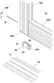
도 1은 본 발명의 사시도.
도 2는 본 발명의 분해사시도.
도 3은 본 발명에 따른 롤러유닛하우징과 커버를 보인 분해사시도.
도 4a,4b는 본 발명에 따른 롤러유닛하우징의 정단면도와 측단면도.
도 5는 본 발명에 따른 커버의 단면도.
도 6a,6b,6c는 본 발명의 다양한 사용상태를 보인 분해사시도.1 is a perspective view of the present invention.
2 is an exploded perspective view of the present invention.
3 is an exploded perspective view showing a roller unit housing and a cover according to the present invention.
Figures 4a and 4b are front and side sectional views of a roller unit housing according to the present invention.
5 is a sectional view of a cover according to the present invention;
6A, 6B and 6C are exploded perspective views showing various use states of the present invention.
이하 첨부된 도면에 따라서 본 발명의 기술적 구성을 상세히 설명하면 다음과 같다.DETAILED DESCRIPTION OF THE PREFERRED EMBODIMENTS Hereinafter, the technical structure of the present invention will be described in detail with reference to the accompanying drawings.
본 발명의 문틀 조립구조는 도 1 내지 도 6a,6b,6c에 도시되는 바와 같이, 중공부(110)와 제1연결부재(120)가 끼워져 나사체결로 고정되는 제1연결부재홈(130)을 구비하는 양측 수직바(100), 상기 양측 수직바(100)의 하부에 배치되어 제1연결부재(120)에 끼워져 고정볼트(210)로 고정되는 제2연결부재(220)를 구비하는 수평바(200)를 포함하는 문틀(10)에 있어서, 상기 수직바(100)의 외벽과 내벽의 하부 중앙에 중공부(110)와 통하도록 수직으로 각각 개방되는 수직장공(140); 상기 수직바(100)의 양측 수직장공(140) 사이로 압입되어 롤러유닛(20)(30)(40)들 중 어느 하나를 선택적으로 수용하는 하부와 내측이 개방된 수용부(310)와, 외측 수직장공(140)으로 끼워지는 삽입부(320)의 외측홈(321)에 형성되어 롤러유닛(20)(30)(40)의 높이조절볼트(21)(31)(41)와 마주하는 하나 이상의 높이조절공(330)을 구비하는 롤러유닛하우징(300); 상기 롤러유닛하우징(300)의 수용부(310)와 통하도록 수평바(200)의 하부 내측에 형성되는 연결부(230)를 더 포함하여 구성된 것을 그 기술적 구성상의 기본적인 특징으로 한다.1 to 6A, 6B, and 6C, the door frame assembly structure of the present invention includes a first
여기서, 본 발명의 문틀 조립구조는 구조가 다른 다양한 구조의 롤러유닛(20)(30)(40)들을 공용으로 설치하여 문틀(10)의 통일된 규격화와 공용화가 가능하고 롤러유닛(20)(30)(40)들을 모두 적용하여 사용할 수 있도록 한 것으로, 이러한 본 발명의 문틀 조립구조에는 수직장공(140)과 연결부(230) 및 롤러유닛하우징(300)이 구비된다.Here, the door frame assembly structure of the present invention is constructed such that the
상기 문틀(10)은 양측 한 쌍의 수직바(100)와 하부용 수평바(200) 및 상부용 수평바(미도시)로 이루어지고, 상기 수직바(100)의 하부와 하부용 수평바(200)는 제1,2연결부재(120)(220)에 의해서 견고하게 연결 고정되며, 상기 수직바(100)의 상부와 상부용 수평바(미도시)는 또 다른 별도의 제1,2연결부재(미도시)에 의해서 견고하게 연결 고정된다. 이때, 상기와 같이 이루어지는 문틀(10)의 내측에는 칸막이 패널(미도시)이 설치된다.The
상기 수직바(100)는 문틀(10)의 양측에 각각 배치되는 것으로, 이러한 수직바(100)의 내부에는 중공부(110)가 형성되고, 수직바(100)의 내측에는 제1연결부재(120)가 끼워져 나사체결로 고정되는 제1연결부재홈(130)이 형성된다. 이때, 상기 수직바(100)는 알루미늄 등의 금속재질로 이루어진다.The
본 발명에 따르면 상기 수직바(100)의 외벽과 내벽의 하부 중앙에는 중공부(110)와 통하도록 수직으로 각각 개방되는 수직장공(140)이 형성된다. 이때, 상기 양측 수직장공(140)의 하부는 롤러유닛하우징(300)을 끼울 수 있도록 각각 개방된다.According to the present invention, a
상기 수평바(200)는 양측 수직바(100)의 하부에 연결되는 것으로, 이러한 수평바(200)의 양측에는 수직바(100)의 제1연결부재(120)에 끼워진 상태에서 고정볼트(120)로 고정되는 제2연결부재(220)가 각각 구비된다. 이때, 상기 수평바(200)는 알루미늄 등의 금속재질로 이루어지고, 상기 제2연결부재(220)는 수평바(200)에 나사체결로 고정된다.The
본 발명에 따르면 상기 수평바(200)의 하부 내측에는 롤러유닛하우징(300)의 수용부(310)와 통하도록 연결부(230)가 형성된다. 이때, 상기 연결부(230)의 하부는 롤러유닛하우징(300)의 수용부(310) 길이보다 길이가 긴 구조의 롤러유닛(40)을 끼울 수 있도록 개방된다.According to the present invention, a connecting
상기 롤러유닛하우징(300)은 수직바(100)의 양측 수직장공(140) 사이로 압입되는 것으로, 이러한 롤러유닛하우징(300)에는 롤러유닛(20)(30)(40)들 중 어느 하나를 선택적으로 수용하는 하부와 내측이 개방된 수용부(310)가 형성되고, 또한 롤러유닛하우징(300)에는 외측 수직장공(140)으로 끼워지는 외측홈(321)을 구비하는 삽입부(320)가 형성되며, 그리고 삽입부(320)의 외측홈(321)에는 롤러유닛(20)(30)(40)의 높이조절볼트(21)(31)(41)와 마주하는 하나 이상의 높이조절공(330)이 형성된다. 이때, 상기 롤러유닛하우징(300)은 합성수지 등으로 이루어지는 것으로, 이러한 롤러유닛하우징(300)은 양측 수직바(100)의 하부에 각각 설치되고, 상기 롤러유닛하우징(300)의 높이조절공(330)은 상부와 하부에 2개를 형성할 수 있다.The
여기서, 본 발명에 따른 상기 롤러유닛하우징(300)은 문틀(10)의 양측 하부에 설치되는 구조가 다른 다양한 롤러유닛(20)(30)(40)들을 공용으로 제한 없이 모두 적용하여 설치할 수 있도록 구성된다.Here, the roller unit housing 300 according to the present invention may be constructed such that
본 발명에 따르면 상기 롤러유닛하우징(300)의 상부에는 수평방향으로 관통되어 삽입부(320)의 내측으로는 하부가 개방된 볼트삽입공(340)이 형성되고, 상기 수평바(200)의 연결부(230) 상부 중앙에는 볼트삽입공(340)과 통하도록 볼트고정홀(240)이 형성되며, 상기 볼트삽입공(340)으로 고정볼트(B)가 끼워져 볼트고정홀(240)에 체결되고, 상기 롤러유닛(20)(30)(40)의 상부에는 고정볼트(B)에 끼워지는 고정부(22)(32)(42)가 구비된다.According to the present invention, a
상기 볼트삽입공(340)은 롤러유닛하우징(300)의 상부에 수평방향으로 관통되는 것으로, 이러한 볼트삽입공(340)의 외부로 노출되는 외측은 하부가 개방되지 않은 원형으로 형성되고, 외부로 노출되지 않는 삽입부(320)의 내측으로 형성되는 볼트삽입공(340)의 하부는 롤러유닛(20)(30)(40)의 고정부(22)(32)(42)를 끼울 수 있도록 개방된다. 이때, 상기 롤러유닛(20)(30)(40)들 중 어느 하나를 롤러유닛하우징(300)의 수용부(310)로 장착하면, 상기 롤러유닛(20)(30)(40)의 고정부(22)(320)(42)는 볼트삽입공(340)으로 끼워지고, 이 상태에서 볼트삽입공(340)으로 고정볼트(B)를 장착하면, 상기 롤러유닛(20)(30)(40)의 고정부(22)(32)(42)는 고정볼트(B)에 끼워지게 된다.The
상기 볼트고정홀(240)은 수평바(200)의 연결부(230) 상부 중앙에 볼트삽입공(340)과 통하도록 형성되는 것으로, 이러한 볼트고정홀(240)에는 고정볼트(B)가 체결된다. 이때, 상기 수직바(100)와 수평바(200)는 제1,2연결부재(120)(220)를 통해 1차적으로 연결 고정되고, 또한 상기 고정볼트(B)를 통해 2차적으로 연결 고정되므로 수직바(100)와 수평바(200)를 한층 더 견고하게 연결 고정할 수 있다.The
참고로, 도 6a는 제1타입의 롤러유닛(20)이 롤러유닛하우징(300)에 설치되는 일 예를 나타낸 것으로, 제1타입의 롤러유닛(20)의 경우에는 롤러(23)의 외경에 반원형으로 요입된 요입부(23a)가 형성되기 때문에, 이러한 경우에는 도 6a에서와 같이 문틀(10)의 하부에는 롤러(23)의 요입부(23a)에 끼워지도록 레일(51)이 돌출된 하부레일(50)이 설치된다. 이때, 상기 롤러(23)의 높이를 조절하는 높이조절볼트(21)는 하부에 형성된 높이조절공(330)과 마주하게 된다.6A shows an example in which the
도 6b는 제2타입의 롤러유닛(30)이 롤러유닛하우징(300)에 설치되는 다른 예를 나타낸 것으로, 제2타입의 롤러유닛(30)의 경우에는 롤러(33)의 외경에 반원형으로 돌출된 돌출부(33a)가 형성되기 때문에, 이러한 경우에는 도 6b에서와 같이 문틀(10)의 하부에는 롤러(33)의 돌출부(33a)가 끼워지도록 롤러홈(61)이 형성된 하부레일(60)이 설치된다. 이때, 상기 롤러(33)의 높이를 조절하는 높이조절볼트(31)는 하부에 형성된 높이조절공(330)과 마주하게 된다.6B shows another example in which the
도 6c는 제3타입의 롤러유닛(40)이 롤러유닛하우징(300)에 설치되는 또 다른 예를 나타낸 것으로, 제3타입의 롤러유닛(40)의 경우에는 롤러(43)의 외경에 반원형으로 돌출된 돌출부(43a)가 형성되기 때문에, 이러한 경우에는 도 6c에서와 같이 문틀(10)의 하부에는 롤러(43)의 돌출부(43a)가 끼워지도록 롤러홈(61)이 형성된 하부레일(60)이 설치된다. 이때, 상기 롤러(43)의 높이를 조절하는 높이조절볼트(41)는 상부에 형성된 높이조절공(330)과 마주하게 된다. 한편, 상기 제3타입의 롤러유닛(40)은 완충수단을 가지는 구조로 롤러유닛하우징(300)의 길이 보다 길게 형성되기 때문에, 조립시 롤러유닛하우징(300)의 수용부(310)와 수평바(200)의 연결부(230)에 길게 연장되도록 설치된다.6C shows another example in which the
본 발명에 따르면 상기 수평바(200)와 롤러유닛하우징(300)의 저면 전,후방에는 길이방향으로 모헤어(H)가 끼워지는 모헤어설치홈(250)(350)이 각각 형성된다. 이때, 상기 롤러유닛하우징(300)의 하부에 모헤어(H)가 설치되므로 양측 수직바(100)와 하부레일(50)(60) 사이의 틈새를 차단할 수 있고, 이를 통해 방음 및 방풍효과를 얻을 수 있다.According to the present invention,
본 발명에 따르면 상기 롤러유닛하우징(300)의 하부에는 수직바(100)의 하단에 걸리는 걸림부(360)가 형성되고, 상기 걸림부(360)의 내측에는 수평바(200)의 일단이 끼워지는 수평바홈(361)이 형성되며, 상기 롤러유닛하우징(300)의 외면에는 다수의 보강리브(370)가 삽입이 용이하도록 상부에서 하부로 폭이 커지는 경사면으로 형성되고, 상기 보강리브(370)의 하부에는 수직바(100)의 중공부(110)에 압입으로 고정되는 고정리브(371)가 수직면으로 형성된다. 이때, 상기 롤러유닛하우징(300)을 수직바(100)의 하부로 압입하면 걸림부(360)가 수직바(100)의 하단에 걸릴 때까지 삽입되고, 압입시 경사면으로 형성된 다수의 보강리브(370)에 의해 용이하게 끼워지면서 수직면으로 형성된 다수의 고정리브(371)가 수직바(100)의 내측에 견고하게 밀착되기 때문에, 별도의 고정나사 등을 사용하지 않고도 롤러유닛하우징(300)을 수직바(100)에 압입으로 견고하게 고정할 수 있다.According to the present invention, the
본 발명에 따르면 상기 삽입부(320)의 외측홈(321)에는 커버(400)가 탈착가능하게 장착되고, 상기 커버(400)의 내측에는 볼트삽입공(340)과 높이조절공(330)에 끼워지는 끼움돌기(410)(420)가 각각 형성되며, 상기 외측홈(321)의 하부와 커버(400)의 내측 하부에는 분리용 경사면(322)(430)이 각각 형성된다. 이때, 상기 롤러유닛하우징(300)의 삽입부(320)에 커버(400)가 탈착가능하게 장착되기 때문에, 평상시 외관이 미려하도록 롤러유닛(20)(30)(40)의 높이조절볼트(21)(31)(41) 및 롤러유닛하우징(300)의 높이조절공(330)과 볼트삽입공(340)이 외부로 노출되는 것을 차단할 수 있다. 한편, 롤러유닛(20)(30)(40)의 높이조절시에는 분리용 경사면(322)(430)으로 일자 드라이버 등을 끼워서 당기면 커버(400)를 용이하게 분리할 수 있다.According to the present invention, a
본 발명에 따르면 상기 롤러유닛하우징(300)의 삽입부(320) 내측에는 수직바(100)의 수직장공(140) 내면에 걸리는 걸림턱(323)이 돌출된다. 이때, 상기 걸림턱(323)은 롤러유닛하우징(300)의 삽입부(320) 강도를 보강함과 동시에 결합력을 증대시킨다.According to the present invention, a locking
본 발명에 따르면 상기 외측홈(321)의 외벽(321a) 내면에는 롤러유닛(20)(30)(40)의 높이조절볼트(21)(31)(41)가 끼워지는 수직장홈(321b)이 형성된다. 이때, 상기 수직장홈(321b)은 롤러유닛(20)(30)(40)의 조립시 높이조절볼트(21)(31)(41)와 높이조절공(330)이 서로 마주하도록 높이조절볼트(21)(31)(41)를 지지하게 된다.According to the present invention, on the inner surface of the
따라서, 이러한 본 발명은 수직바(100)의 하부에 다양한 구조의 롤러유닛(20)(30)(40)들 중 어느 하나를 선택적으로 수용하는 롤러유닛하우징(300)이 설치되기 때문에, 문틀(10)의 양측 하부에 설치되는 구조가 다른 다양한 롤러유닛(20)(30)(40)을 공용으로 설치할 수 있고, 이를 통해 문틀(10)의 통일된 규격화와 공용화가 가능하고 구조에 관계없이 여러 가지 구조가 다른 롤러유닛(20)(30)(40)을 현장 여건에 맞게 쉽고 간단하게 제한 없이 모두 적용하여 사용할 수 있는 장점이 있다.Therefore, the present invention is provided with the
또한 이러한 본 발명은 롤러유닛하우징(300)과 수평바(200)의 하부에 모헤어(H)가 끼워지는 모헤어설치홈(250)(350)이 각각 형성되기 때문에, 모헤어설치홈(250)(350)에 끼워진 모헤어(H)로 문틀(10)과 하부레일(50)(60) 사이의 틈새를 차단할 수 있고, 이를 통해 문틀(10)의 하부에 방음 및 방풍기능을 부여할 수 있는 장점이 있다.In addition, since the
그리고 이러한 본 발명은 롤러유닛하우징(300)의 삽입부(320)에 구비된 외측홈(321)으로 커버(400)가 탈착가능하게 장착되기 때문에, 평상시 롤러유닛(20)(30)(40)의 높이조절볼트(21)(31)(41) 및 롤러유닛하우징(300)의 높이조절공(330)과 볼트삽입공(340)이 외부로 노출되는 것을 차단하여 외관이 미려하도록 할 수 있는 장점이 있다.The present invention is also applicable to the
10 : 문틀 20,30,40 : 롤러유닛
21,31,41 : 높이조절볼트 22,32,42 : 고정부
100 : 수직바 110 : 중공부
120 : 제1연결부재 130 : 제1연결부재홈
140 : 수직장공 200 : 수평바
210 : 고정볼트 220 : 제2연결부재
230 : 연결부 240 : 볼트고정홀
250 : 모헤어설치홈 300 : 롤러유닛하우징
310 : 수용부 320 : 삽입부
321 : 외측홈 321a : 외벽
321b : 수직장홈 322 : 경사면
323 : 걸림턱 330 : 높이조절공
340 : 볼트삽입공 350 : 모헤어설치홈
360 : 걸림부 361 : 수평바홈
370 : 보강리브 371 : 고정리브
400 : 커버 410,420 : 끼움돌기
430 : 경사면 B : 고정볼트
H : 모헤어10:
21, 31, 41:
100: vertical bar 110: hollow
120: first connecting member 130: first connecting member groove
140: vertical slot 200: horizontal bar
210: fixing bolt 220: second connecting member
230: connection part 240: bolt fixing hole
250: mohair mounting groove 300: roller unit housing
310: receptacle 320:
321:
321b: vertical groove 322: inclined surface
323: Retaining jaws 330: Height adjusting balls
340: bolt insertion hole 350: mohair installation groove
360: Retaining portion 361: Horizontal bar groove
370: reinforcing ribs 371:
400:
430: slope B: fixing bolt
H: mohair
Claims (7)
상기 롤러유닛하우징(300)의 상부에는 수평방향으로 관통되어 삽입부(320)의 내측으로는 하부가 개방된 볼트삽입공(340)이 형성되고, 상기 수평바(200)의 연결부(230) 상부 중앙에는 볼트삽입공(340)과 통하도록 볼트고정홀(240)이 형성되며, 상기 볼트삽입공(340)으로 고정볼트(B)가 끼워져 볼트고정홀(240)에 체결되고, 상기 롤러유닛(20)(30)(40)의 상부에는 고정볼트(B)에 끼워지는 고정부(22)(32)(42)가 구비된 것을 특징으로 하는 문틀 조립구조,Side vertical bars 100 having a first connecting member groove 130 in which the hollow portion 110 and the first connecting member 120 are fitted and fixed by screwing, A door frame 10 including a horizontal bar 200 having a second connection member 220 fitted in the first connection member 120 and fixed by a fixing bolt 210; A vertical slot 140 vertically opened to communicate with the hollow portion 110 at the lower center of the outer wall and the inner wall of the vertical bar 100; A receiving portion 310 which is press-fitted between both vertical slots 140 of the vertical bar 100 to selectively receive any one of the roller units 20, 30 and 40, (41) of the roller unit (20), (30), and (40) formed in the outer groove (321) of the insertion portion (320) inserted into the vertical slot (140) A roller unit housing 300 having a height adjustment hole 330; And a connection part 230 formed inside the lower part of the horizontal bar 200 to communicate with the receiving part 310 of the roller unit housing 300,
A bolt insertion hole 340 is formed at an upper portion of the roller unit housing 300 in a horizontal direction so that the lower portion of the bolt insertion hole 340 is formed at an inner side of the insertion portion 320, A fixing bolt B is inserted into the bolt insertion hole 340 so as to be fastened to the bolt fixing hole 240 and the roller unit 340 20, 30 and 40 are provided with fixing portions 22, 32 and 42 to be fitted to the fixing bolts B,
Priority Applications (1)
| Application Number | Priority Date | Filing Date | Title |
|---|---|---|---|
| KR1020150059795A KR101753315B1 (en) | 2015-04-28 | 2015-04-28 | Assembling structure of door frame |
Applications Claiming Priority (1)
| Application Number | Priority Date | Filing Date | Title |
|---|---|---|---|
| KR1020150059795A KR101753315B1 (en) | 2015-04-28 | 2015-04-28 | Assembling structure of door frame |
Publications (2)
| Publication Number | Publication Date |
|---|---|
| KR20160128054A KR20160128054A (en) | 2016-11-07 |
| KR101753315B1 true KR101753315B1 (en) | 2017-07-05 |
Family
ID=57529689
Family Applications (1)
| Application Number | Title | Priority Date | Filing Date |
|---|---|---|---|
| KR1020150059795A Expired - Fee Related KR101753315B1 (en) | 2015-04-28 | 2015-04-28 | Assembling structure of door frame |
Country Status (1)
| Country | Link |
|---|---|
| KR (1) | KR101753315B1 (en) |
Cited By (3)
| Publication number | Priority date | Publication date | Assignee | Title |
|---|---|---|---|---|
| KR20200037707A (en) | 2018-10-01 | 2020-04-09 | 정영호 | Hollow Frame Type Door |
| KR20200058346A (en) | 2020-05-18 | 2020-05-27 | 정영호 | Hollow Frame Type Door |
| KR20240010874A (en) | 2022-07-18 | 2024-01-25 | 신명준 | Door frame assembling structure of sliding door for easy assembly |
Families Citing this family (1)
| Publication number | Priority date | Publication date | Assignee | Title |
|---|---|---|---|---|
| CN107448108B (en) * | 2017-09-30 | 2020-06-19 | 贵州筑信达创科技有限公司 | Transverse rod body side sliding anti-theft door |
Citations (2)
| Publication number | Priority date | Publication date | Assignee | Title |
|---|---|---|---|---|
| JP2001073619A (en) | 1999-09-07 | 2001-03-21 | Frontier:Kk | Door car |
| KR200232620Y1 (en) * | 2001-02-23 | 2001-09-28 | 주식회사 엘지씨아이 | Airtight Member to be Inserted in Window Sash |
Family Cites Families (1)
| Publication number | Priority date | Publication date | Assignee | Title |
|---|---|---|---|---|
| KR101303277B1 (en) | 2011-04-11 | 2013-09-04 | 안중식 | Door assembly of a sliding window and assembling method threreof |
-
2015
- 2015-04-28 KR KR1020150059795A patent/KR101753315B1/en not_active Expired - Fee Related
Patent Citations (2)
| Publication number | Priority date | Publication date | Assignee | Title |
|---|---|---|---|---|
| JP2001073619A (en) | 1999-09-07 | 2001-03-21 | Frontier:Kk | Door car |
| KR200232620Y1 (en) * | 2001-02-23 | 2001-09-28 | 주식회사 엘지씨아이 | Airtight Member to be Inserted in Window Sash |
Cited By (3)
| Publication number | Priority date | Publication date | Assignee | Title |
|---|---|---|---|---|
| KR20200037707A (en) | 2018-10-01 | 2020-04-09 | 정영호 | Hollow Frame Type Door |
| KR20200058346A (en) | 2020-05-18 | 2020-05-27 | 정영호 | Hollow Frame Type Door |
| KR20240010874A (en) | 2022-07-18 | 2024-01-25 | 신명준 | Door frame assembling structure of sliding door for easy assembly |
Also Published As
| Publication number | Publication date |
|---|---|
| KR20160128054A (en) | 2016-11-07 |
Similar Documents
| Publication | Publication Date | Title |
|---|---|---|
| US9167939B2 (en) | Shower door assembly | |
| CN1158732C (en) | Switch cabinet | |
| KR20160128054A (en) | Assembling structure of door frame | |
| EP3768933B1 (en) | Assembly of a box, in particular a roller shutter box, and mounting frame | |
| EP2093362A1 (en) | Method and clamping system for the fixation of a hinge or other metal work on profiles for windows and doors | |
| US6155658A (en) | Profiled frame for a switchgear cabinet | |
| CN110821924B (en) | Clamp anchor for fastening a ferrous object to a hollow profile of a window or door | |
| US20030146011A1 (en) | Housing for receiving electric and/or electronic assemblies | |
| KR200411765Y1 (en) | Wind-resistant reinforcement auxiliary unit of window | |
| KR200491312Y1 (en) | Sliding door handle | |
| KR200144934Y1 (en) | Frame fasteners for windows | |
| CN106368542B (en) | Configuration system for hinges on cavity profiles | |
| KR20110038345A (en) | Mortis lock assembly for door | |
| KR102093486B1 (en) | Connecting Structure of Vertical Frame and Horizontal Frame of the Door | |
| KR200377241Y1 (en) | Window frame with subsidiary window frame | |
| JPH038787Y2 (en) | ||
| KR200397192Y1 (en) | Door frame | |
| KR102721155B1 (en) | Installation structure of door handle applied with narrow side frame | |
| KR0119111Y1 (en) | Door lock for aluminum chassis door | |
| KR200331946Y1 (en) | Adiabatic device of aluminum window | |
| KR200233551Y1 (en) | A window car | |
| KR0120200Y1 (en) | Curtain fixing frame | |
| KR200148759Y1 (en) | Mounting prevention cover installation structure of window car | |
| JP2939796B2 (en) | Glass plate holding frame rod in glass panel | |
| KR200294096Y1 (en) | Structure for assembling end cover |
Legal Events
| Date | Code | Title | Description |
|---|---|---|---|
| A201 | Request for examination | ||
| PA0109 | Patent application |
St.27 status event code: A-0-1-A10-A12-nap-PA0109 |
|
| PA0201 | Request for examination |
St.27 status event code: A-1-2-D10-D11-exm-PA0201 |
|
| D13-X000 | Search requested |
St.27 status event code: A-1-2-D10-D13-srh-X000 |
|
| D14-X000 | Search report completed |
St.27 status event code: A-1-2-D10-D14-srh-X000 |
|
| E902 | Notification of reason for refusal | ||
| PE0902 | Notice of grounds for rejection |
St.27 status event code: A-1-2-D10-D21-exm-PE0902 |
|
| PG1501 | Laying open of application |
St.27 status event code: A-1-1-Q10-Q12-nap-PG1501 |
|
| E13-X000 | Pre-grant limitation requested |
St.27 status event code: A-2-3-E10-E13-lim-X000 |
|
| P11-X000 | Amendment of application requested |
St.27 status event code: A-2-2-P10-P11-nap-X000 |
|
| P13-X000 | Application amended |
St.27 status event code: A-2-2-P10-P13-nap-X000 |
|
| E701 | Decision to grant or registration of patent right | ||
| PE0701 | Decision of registration |
St.27 status event code: A-1-2-D10-D22-exm-PE0701 |
|
| GRNT | Written decision to grant | ||
| PR0701 | Registration of establishment |
St.27 status event code: A-2-4-F10-F11-exm-PR0701 |
|
| PR1002 | Payment of registration fee |
St.27 status event code: A-2-2-U10-U11-oth-PR1002 Fee payment year number: 1 |
|
| PG1601 | Publication of registration |
St.27 status event code: A-4-4-Q10-Q13-nap-PG1601 |
|
| R18-X000 | Changes to party contact information recorded |
St.27 status event code: A-5-5-R10-R18-oth-X000 |
|
| P22-X000 | Classification modified |
St.27 status event code: A-4-4-P10-P22-nap-X000 |
|
| FPAY | Annual fee payment |
Payment date: 20200504 Year of fee payment: 4 |
|
| PR1001 | Payment of annual fee |
St.27 status event code: A-4-4-U10-U11-oth-PR1001 Fee payment year number: 4 |
|
| FPAY | Annual fee payment |
Payment date: 20210527 Year of fee payment: 5 |
|
| PR1001 | Payment of annual fee |
St.27 status event code: A-4-4-U10-U11-oth-PR1001 Fee payment year number: 5 |
|
| FPAY | Annual fee payment |
Payment date: 20220530 Year of fee payment: 6 |
|
| PR1001 | Payment of annual fee |
St.27 status event code: A-4-4-U10-U11-oth-PR1001 Fee payment year number: 6 |
|
| PC1903 | Unpaid annual fee |
St.27 status event code: A-4-4-U10-U13-oth-PC1903 Not in force date: 20230628 Payment event data comment text: Termination Category : DEFAULT_OF_REGISTRATION_FEE |
|
| PC1903 | Unpaid annual fee |
St.27 status event code: N-4-6-H10-H13-oth-PC1903 Ip right cessation event data comment text: Termination Category : DEFAULT_OF_REGISTRATION_FEE Not in force date: 20230628 |