KR101663787B1 - Atraumatic stent and method and apparatus for making the same - Google Patents
Atraumatic stent and method and apparatus for making the same Download PDFInfo
- Publication number
- KR101663787B1 KR101663787B1 KR1020117019662A KR20117019662A KR101663787B1 KR 101663787 B1 KR101663787 B1 KR 101663787B1 KR 1020117019662 A KR1020117019662 A KR 1020117019662A KR 20117019662 A KR20117019662 A KR 20117019662A KR 101663787 B1 KR101663787 B1 KR 101663787B1
- Authority
- KR
- South Korea
- Prior art keywords
- mandrel
- twisted
- filament
- carrier
- stent
- Prior art date
Links
Images


Classifications
-
- D—TEXTILES; PAPER
- D04—BRAIDING; LACE-MAKING; KNITTING; TRIMMINGS; NON-WOVEN FABRICS
- D04C—BRAIDING OR MANUFACTURE OF LACE, INCLUDING BOBBIN-NET OR CARBONISED LACE; BRAIDING MACHINES; BRAID; LACE
- D04C1/00—Braid or lace, e.g. pillow-lace; Processes for the manufacture thereof
- D04C1/06—Braid or lace serving particular purposes
-
- D—TEXTILES; PAPER
- D04—BRAIDING; LACE-MAKING; KNITTING; TRIMMINGS; NON-WOVEN FABRICS
- D04C—BRAIDING OR MANUFACTURE OF LACE, INCLUDING BOBBIN-NET OR CARBONISED LACE; BRAIDING MACHINES; BRAID; LACE
- D04C3/00—Braiding or lacing machines
- D04C3/48—Auxiliary devices
-
- A—HUMAN NECESSITIES
- A61—MEDICAL OR VETERINARY SCIENCE; HYGIENE
- A61F—FILTERS IMPLANTABLE INTO BLOOD VESSELS; PROSTHESES; DEVICES PROVIDING PATENCY TO, OR PREVENTING COLLAPSING OF, TUBULAR STRUCTURES OF THE BODY, e.g. STENTS; ORTHOPAEDIC, NURSING OR CONTRACEPTIVE DEVICES; FOMENTATION; TREATMENT OR PROTECTION OF EYES OR EARS; BANDAGES, DRESSINGS OR ABSORBENT PADS; FIRST-AID KITS
- A61F2/00—Filters implantable into blood vessels; Prostheses, i.e. artificial substitutes or replacements for parts of the body; Appliances for connecting them with the body; Devices providing patency to, or preventing collapsing of, tubular structures of the body, e.g. stents
- A61F2/82—Devices providing patency to, or preventing collapsing of, tubular structures of the body, e.g. stents
- A61F2/86—Stents in a form characterised by the wire-like elements; Stents in the form characterised by a net-like or mesh-like structure
- A61F2/90—Stents in a form characterised by the wire-like elements; Stents in the form characterised by a net-like or mesh-like structure characterised by a net-like or mesh-like structure
-
- D—TEXTILES; PAPER
- D02—YARNS; MECHANICAL FINISHING OF YARNS OR ROPES; WARPING OR BEAMING
- D02G—CRIMPING OR CURLING FIBRES, FILAMENTS, THREADS, OR YARNS; YARNS OR THREADS
- D02G1/00—Producing crimped or curled fibres, filaments, yarns, or threads, giving them latent characteristics
- D02G1/02—Producing crimped or curled fibres, filaments, yarns, or threads, giving them latent characteristics by twisting, fixing the twist and backtwisting, i.e. by imparting false twist
-
- D—TEXTILES; PAPER
- D02—YARNS; MECHANICAL FINISHING OF YARNS OR ROPES; WARPING OR BEAMING
- D02G—CRIMPING OR CURLING FIBRES, FILAMENTS, THREADS, OR YARNS; YARNS OR THREADS
- D02G3/00—Yarns or threads, e.g. fancy yarns; Processes or apparatus for the production thereof, not otherwise provided for
- D02G3/22—Yarns or threads characterised by constructional features, e.g. blending, filament/fibre
- D02G3/26—Yarns or threads characterised by constructional features, e.g. blending, filament/fibre with characteristics dependent on the amount or direction of twist
- D02G3/28—Doubled, plied, or cabled threads
-
- D—TEXTILES; PAPER
- D02—YARNS; MECHANICAL FINISHING OF YARNS OR ROPES; WARPING OR BEAMING
- D02G—CRIMPING OR CURLING FIBRES, FILAMENTS, THREADS, OR YARNS; YARNS OR THREADS
- D02G3/00—Yarns or threads, e.g. fancy yarns; Processes or apparatus for the production thereof, not otherwise provided for
- D02G3/44—Yarns or threads characterised by the purpose for which they are designed
- D02G3/448—Yarns or threads for use in medical applications
-
- D—TEXTILES; PAPER
- D04—BRAIDING; LACE-MAKING; KNITTING; TRIMMINGS; NON-WOVEN FABRICS
- D04C—BRAIDING OR MANUFACTURE OF LACE, INCLUDING BOBBIN-NET OR CARBONISED LACE; BRAIDING MACHINES; BRAID; LACE
- D04C3/00—Braiding or lacing machines
- D04C3/02—Braiding or lacing machines with spool carriers guided by track plates or by bobbin heads exclusively
- D04C3/14—Spool carriers
-
- A—HUMAN NECESSITIES
- A61—MEDICAL OR VETERINARY SCIENCE; HYGIENE
- A61F—FILTERS IMPLANTABLE INTO BLOOD VESSELS; PROSTHESES; DEVICES PROVIDING PATENCY TO, OR PREVENTING COLLAPSING OF, TUBULAR STRUCTURES OF THE BODY, e.g. STENTS; ORTHOPAEDIC, NURSING OR CONTRACEPTIVE DEVICES; FOMENTATION; TREATMENT OR PROTECTION OF EYES OR EARS; BANDAGES, DRESSINGS OR ABSORBENT PADS; FIRST-AID KITS
- A61F2/00—Filters implantable into blood vessels; Prostheses, i.e. artificial substitutes or replacements for parts of the body; Appliances for connecting them with the body; Devices providing patency to, or preventing collapsing of, tubular structures of the body, e.g. stents
- A61F2/82—Devices providing patency to, or preventing collapsing of, tubular structures of the body, e.g. stents
- A61F2/86—Stents in a form characterised by the wire-like elements; Stents in the form characterised by a net-like or mesh-like structure
- A61F2/90—Stents in a form characterised by the wire-like elements; Stents in the form characterised by a net-like or mesh-like structure characterised by a net-like or mesh-like structure
- A61F2/91—Stents in a form characterised by the wire-like elements; Stents in the form characterised by a net-like or mesh-like structure characterised by a net-like or mesh-like structure made from perforated sheet material or tubes, e.g. perforated by laser cuts or etched holes
- A61F2/915—Stents in a form characterised by the wire-like elements; Stents in the form characterised by a net-like or mesh-like structure characterised by a net-like or mesh-like structure made from perforated sheet material or tubes, e.g. perforated by laser cuts or etched holes with bands having a meander structure, adjacent bands being connected to each other
- A61F2002/91508—Stents in a form characterised by the wire-like elements; Stents in the form characterised by a net-like or mesh-like structure characterised by a net-like or mesh-like structure made from perforated sheet material or tubes, e.g. perforated by laser cuts or etched holes with bands having a meander structure, adjacent bands being connected to each other the meander having a difference in amplitude along the band
-
- A—HUMAN NECESSITIES
- A61—MEDICAL OR VETERINARY SCIENCE; HYGIENE
- A61F—FILTERS IMPLANTABLE INTO BLOOD VESSELS; PROSTHESES; DEVICES PROVIDING PATENCY TO, OR PREVENTING COLLAPSING OF, TUBULAR STRUCTURES OF THE BODY, e.g. STENTS; ORTHOPAEDIC, NURSING OR CONTRACEPTIVE DEVICES; FOMENTATION; TREATMENT OR PROTECTION OF EYES OR EARS; BANDAGES, DRESSINGS OR ABSORBENT PADS; FIRST-AID KITS
- A61F2/00—Filters implantable into blood vessels; Prostheses, i.e. artificial substitutes or replacements for parts of the body; Appliances for connecting them with the body; Devices providing patency to, or preventing collapsing of, tubular structures of the body, e.g. stents
- A61F2/82—Devices providing patency to, or preventing collapsing of, tubular structures of the body, e.g. stents
- A61F2/86—Stents in a form characterised by the wire-like elements; Stents in the form characterised by a net-like or mesh-like structure
- A61F2/90—Stents in a form characterised by the wire-like elements; Stents in the form characterised by a net-like or mesh-like structure characterised by a net-like or mesh-like structure
- A61F2/91—Stents in a form characterised by the wire-like elements; Stents in the form characterised by a net-like or mesh-like structure characterised by a net-like or mesh-like structure made from perforated sheet material or tubes, e.g. perforated by laser cuts or etched holes
- A61F2/915—Stents in a form characterised by the wire-like elements; Stents in the form characterised by a net-like or mesh-like structure characterised by a net-like or mesh-like structure made from perforated sheet material or tubes, e.g. perforated by laser cuts or etched holes with bands having a meander structure, adjacent bands being connected to each other
- A61F2002/91516—Stents in a form characterised by the wire-like elements; Stents in the form characterised by a net-like or mesh-like structure characterised by a net-like or mesh-like structure made from perforated sheet material or tubes, e.g. perforated by laser cuts or etched holes with bands having a meander structure, adjacent bands being connected to each other the meander having a change in frequency along the band
-
- A—HUMAN NECESSITIES
- A61—MEDICAL OR VETERINARY SCIENCE; HYGIENE
- A61F—FILTERS IMPLANTABLE INTO BLOOD VESSELS; PROSTHESES; DEVICES PROVIDING PATENCY TO, OR PREVENTING COLLAPSING OF, TUBULAR STRUCTURES OF THE BODY, e.g. STENTS; ORTHOPAEDIC, NURSING OR CONTRACEPTIVE DEVICES; FOMENTATION; TREATMENT OR PROTECTION OF EYES OR EARS; BANDAGES, DRESSINGS OR ABSORBENT PADS; FIRST-AID KITS
- A61F2/00—Filters implantable into blood vessels; Prostheses, i.e. artificial substitutes or replacements for parts of the body; Appliances for connecting them with the body; Devices providing patency to, or preventing collapsing of, tubular structures of the body, e.g. stents
- A61F2/82—Devices providing patency to, or preventing collapsing of, tubular structures of the body, e.g. stents
- A61F2/86—Stents in a form characterised by the wire-like elements; Stents in the form characterised by a net-like or mesh-like structure
- A61F2/90—Stents in a form characterised by the wire-like elements; Stents in the form characterised by a net-like or mesh-like structure characterised by a net-like or mesh-like structure
- A61F2/91—Stents in a form characterised by the wire-like elements; Stents in the form characterised by a net-like or mesh-like structure characterised by a net-like or mesh-like structure made from perforated sheet material or tubes, e.g. perforated by laser cuts or etched holes
- A61F2/915—Stents in a form characterised by the wire-like elements; Stents in the form characterised by a net-like or mesh-like structure characterised by a net-like or mesh-like structure made from perforated sheet material or tubes, e.g. perforated by laser cuts or etched holes with bands having a meander structure, adjacent bands being connected to each other
- A61F2002/91525—Stents in a form characterised by the wire-like elements; Stents in the form characterised by a net-like or mesh-like structure characterised by a net-like or mesh-like structure made from perforated sheet material or tubes, e.g. perforated by laser cuts or etched holes with bands having a meander structure, adjacent bands being connected to each other within the whole structure different bands showing different meander characteristics, e.g. frequency or amplitude
-
- A—HUMAN NECESSITIES
- A61—MEDICAL OR VETERINARY SCIENCE; HYGIENE
- A61F—FILTERS IMPLANTABLE INTO BLOOD VESSELS; PROSTHESES; DEVICES PROVIDING PATENCY TO, OR PREVENTING COLLAPSING OF, TUBULAR STRUCTURES OF THE BODY, e.g. STENTS; ORTHOPAEDIC, NURSING OR CONTRACEPTIVE DEVICES; FOMENTATION; TREATMENT OR PROTECTION OF EYES OR EARS; BANDAGES, DRESSINGS OR ABSORBENT PADS; FIRST-AID KITS
- A61F2230/00—Geometry of prostheses classified in groups A61F2/00 - A61F2/26 or A61F2/82 or A61F9/00 or A61F11/00 or subgroups thereof
- A61F2230/0063—Three-dimensional shapes
- A61F2230/0069—Three-dimensional shapes cylindrical
-
- A—HUMAN NECESSITIES
- A61—MEDICAL OR VETERINARY SCIENCE; HYGIENE
- A61F—FILTERS IMPLANTABLE INTO BLOOD VESSELS; PROSTHESES; DEVICES PROVIDING PATENCY TO, OR PREVENTING COLLAPSING OF, TUBULAR STRUCTURES OF THE BODY, e.g. STENTS; ORTHOPAEDIC, NURSING OR CONTRACEPTIVE DEVICES; FOMENTATION; TREATMENT OR PROTECTION OF EYES OR EARS; BANDAGES, DRESSINGS OR ABSORBENT PADS; FIRST-AID KITS
- A61F2240/00—Manufacturing or designing of prostheses classified in groups A61F2/00 - A61F2/26 or A61F2/82 or A61F9/00 or A61F11/00 or subgroups thereof
-
- A—HUMAN NECESSITIES
- A61—MEDICAL OR VETERINARY SCIENCE; HYGIENE
- A61F—FILTERS IMPLANTABLE INTO BLOOD VESSELS; PROSTHESES; DEVICES PROVIDING PATENCY TO, OR PREVENTING COLLAPSING OF, TUBULAR STRUCTURES OF THE BODY, e.g. STENTS; ORTHOPAEDIC, NURSING OR CONTRACEPTIVE DEVICES; FOMENTATION; TREATMENT OR PROTECTION OF EYES OR EARS; BANDAGES, DRESSINGS OR ABSORBENT PADS; FIRST-AID KITS
- A61F2250/00—Special features of prostheses classified in groups A61F2/00 - A61F2/26 or A61F2/82 or A61F9/00 or A61F11/00 or subgroups thereof
- A61F2250/0014—Special features of prostheses classified in groups A61F2/00 - A61F2/26 or A61F2/82 or A61F9/00 or A61F11/00 or subgroups thereof having different values of a given property or geometrical feature, e.g. mechanical property or material property, at different locations within the same prosthesis
- A61F2250/0018—Special features of prostheses classified in groups A61F2/00 - A61F2/26 or A61F2/82 or A61F9/00 or A61F11/00 or subgroups thereof having different values of a given property or geometrical feature, e.g. mechanical property or material property, at different locations within the same prosthesis differing in elasticity, stiffness or compressibility
-
- D—TEXTILES; PAPER
- D04—BRAIDING; LACE-MAKING; KNITTING; TRIMMINGS; NON-WOVEN FABRICS
- D04C—BRAIDING OR MANUFACTURE OF LACE, INCLUDING BOBBIN-NET OR CARBONISED LACE; BRAIDING MACHINES; BRAID; LACE
- D04C1/00—Braid or lace, e.g. pillow-lace; Processes for the manufacture thereof
- D04C1/02—Braid or lace, e.g. pillow-lace; Processes for the manufacture thereof made from particular materials
-
- D—TEXTILES; PAPER
- D10—INDEXING SCHEME ASSOCIATED WITH SUBLASSES OF SECTION D, RELATING TO TEXTILES
- D10B—INDEXING SCHEME ASSOCIATED WITH SUBLASSES OF SECTION D, RELATING TO TEXTILES
- D10B2509/00—Medical; Hygiene
- D10B2509/06—Vascular grafts; stents
Abstract
스텐트를 꼬는 방법은 필라멘트를 장력이 가해진 꼬임 캐리어에 감지 않고 장력이 가해진 꼬임 캐리어를 사용하여 맨드렐 주위로 다수의 기다란 필라멘트를 꼬아서 비외상성 단부를 갖는 꼬아진 스텐트를 형성하는 것을 포함한다.The method of twisting a stent includes twisting a plurality of elongate filaments around the mandrel using a twisted carrier tensioned without sensing the filament to a twisted carrier applied with tension to form a twisted stent having a non-traumatic end.
Description
관련출원의 상호 참조Cross reference of related application
본 출원은 2009년 1월 26일에 출원된 미합중국 특허 가출원 제 61/147,307호의 이익을 주장하며, 여기서는 그 내용을 언급함으로써 인용한다.This application claims the benefit of U.S. Provisional Patent Application Serial No. 61 / 147,307, filed January 26, 2009, which is incorporated herein by reference.
본 발명은 비외상성 스텐트 및 그를 제조하는 방법, 장치 및 시스템에 관한 것이다. 보다 구체적으로 본 발명은 비외상성 꼬아진(braided) 스텐트 및 그를 제조하는 꼬는 방법, 꼬임 맨드렐 및 꼬임기에 관한 것이다.The present invention relates to a non-traumatic stent and a method, apparatus and system for manufacturing the same. More particularly, the present invention relates to non-traumatic braided stents and to a twisting method, twist mandrel and kink for making same.
꼬아진 스텐트는 전형적으로 매끈한 맨드렐상에서 꼬아졌다. 꼬임 와이어의 단부는 일반적으로 꼬임 맨드렐의 단부를 지나서 모아지고 그 와이어들은 일반적으로 묶거나 탭핑에 의해 맨드렐 단부에 고정되고 그 후에 손이나 기계에 의해 꼬임이 시작된다.The stranded stent was typically twisted over a smooth mandrel. The ends of the twisted wire are generally gathered past the ends of the twisted mandrel and the wires are generally secured to the mandrel end by tying or tapping and then twisted by the hand or machine.
꼬임 각도는 스텐트 와이어가 맨드렐 위에 배치되는 각도에 따라서 조절되었다. 그러나 많은 스텐트는 꼬임 중에 와이어에 부여된 페리스(ferees)의 결과로서 꼬임중에 이동하거나 움직일 수 있는 금속 와이어를 사용한다. 이는 결국 특히 확개형, 확장형 및/또는 테이퍼형 스텐트 같이 직경이 변화되어 꼬아진 스텐트에 있어서 스텐트를 통한 꼬임각도가 변화되게 할 수 있다. 꼬임 각도의 변화는 이렇게 형성된 스텐트의 반경방향 팽창력 또는 압축력 또는 전개력이 바람직하지 못하게 변화되는 것으로 이어질 수 있다. 이런 변화는 또한 스텐트를 가로지르는 개구부의 사이즈, 예를 들어 셀 사이즈의 일관성에 영향을 줄 수 있다.The twist angle was adjusted according to the angle at which the stent wire was placed on the mandrel. However, many stents use metal wires that can move or move during twisting as a result of the fines given to the wire during twisting. This can eventually lead to varying twist angles through the stent in a twisted stent, such as in particular a bifurcated, expandable and / or tapered stent. A change in the twist angle can lead to an undesirably changing radial expansion force or compressive or deploying force of the thus formed stent. This change may also affect the size of the opening across the stent, e.g., the consistency of the cell size.
스텐트에 사용되는 와이어는 일반적으로 스풀로부터 맨드렐 위로 공급된다. 이런 방식으로 꼬임 과정 중에 충분한 재료를 맨드렐에 공급한 후에 그 결과의 긴 스텐트를 다수의 작은 스텐트로 절단함으로써 다수의 스텐트들이 형성될 수 있다. 긴 스텐트를 꼬은 후에, 맨드렐 단부를 지나서 모아진 와이어 부분들은 트리밍되었다. 이렇게 과도한 와이어를 트리밍하면 불필요하게 재료를 낭비하게 된다. 초기의 많은 스텐트들은 단순히 스테인레스 스틸 와이어로 꼬아지므로, 이 과잉 와이어 재료를 폐기하는 비용은 최소였다. 그러나 최근이 되어 니티놀이나 복합 니티놀 같은 보다 고가의 재료의 스텐트 와이어가 사용되었다. 폐기되는 재료의 비용은 더욱 더 높아졌다.The wire used for the stent is typically fed from the spool over the mandrel. In this way, a large number of stents can be formed by feeding sufficient material to the mandrel during the twisting process and then cutting the resulting long stent into a plurality of small stents. After twisting the long stent, the wire segments gathered past the end of the mandrel were trimmed. Trimming this excess wire will waste material unnecessarily. Since many of the early stents were simply twisted with stainless steel wires, the cost of disposing of this excess wire material was minimal. Recently, however, stent wires of more expensive materials such as Nitinol or Compound Nitinol have been used. The cost of the material to be discarded is even higher.
따라서, 재료 비용을 최소화하고 꼬임각도를 포함한 스텐트 구조도 최소화한 스텐트를 꼬기 위한 방법을 제공하는 기술적인 필요성이 있다. 또한 비외상성 스텐트의 대량 생산을 가능하게 하면서 비외상성 스텐트를 한결같이 제조하기 위해 스텐트의 꼬임각도와 비외상성 단부의 사이즈 및 배향을 조절 가능하게 제공할 수 있도록 개별적인 와이어 길이부로부터 비외상성 단부를 갖는 스텐트를 꼬는 방법을 제공하는 기술적인 필요성이 있다. 또한, 필요에 따라서 재료관리를 포함하고 어떤 특정 량의 맞춤형 스텐트도 만들어낼 수 있는 능력을 포함하여 스텐트 사양을 보다 엄밀하게 조절하기 위하여 스텐트 제조를 최적화할 필요가 있다.Therefore, there is a technical need to provide a method for twisting a stent that minimizes material cost and minimizes stent structure, including twist angle. The present invention also provides a stent having a non-traumatic end from an individual wire length to provide adjustable stent angle and non-traumatic end size and orientation for uniform production of non-traumatic stents while enabling mass production of non-traumatic stents. There is a technical need to provide a way to twist. In addition, there is a need to optimize stent production to more closely control the stent specification, including the ability to include material management as needed and to produce any specific amount of customized stents.
본 발명은 종래기술의 바람직하지 못한 사항들을 회피하고 해결하는 꼬는 방법, 꼬임 맨드렐, 꼬임기 및 꼬아진 스텐트를 제공한다. 본 발명의 꼬아진 스텐트는 실질적으로 조절된 꼬임각도를 갖는데, 필요에 따라서 종방향 확대부 전체에 걸쳐서 실질적으로 일정한 꼬임각도를 포함하고, 테이퍼부, 확개부 및/또는 확장부 같은 직경이 변화된 부분들을 포함한다. 예를 들어, 직경이 변화된 부분을 포함하여 스텐트의 종방향 확대부 전체에 걸쳐서 실질적으로 일정한 꼬임각도 예를 들어 110°가 바람직할 수 있지만, 여기에 한정되는 것은 아니다. 추가적으로 본 발명의 꼬아진 스텐트는 직경이 변화된 부분들을 가질 수 있는데, 여기서 꼬임각도는 하나의 직경변화부에서의 꼬임각도가 다른 직경변화부에 비하여 다르도록 조절되어 있으며 그리고/또는 스텐트의 종방향 확대부에 비하여 하나 이상의 직경변화부에서 다르도록 조절되어 있다. 또한, 본 발명의 조절된 꼬임각도는 일단부에서 한 각도, 예를 들어 90°내지 반대측의 제 2 단부에서 다른 각도, 예를 들어 120°까지 변화될 수 있는데, 이 각도들은 여기에 한정되는 것은 아니며, 단부 각도뿐만 아니라 서로 반대측의 양단부 사이의 천이 각도 모두가 조절되어 있다. 이런 독창적인 스텐트는 특히 특별히 설계된 홈 및 돌기를 갖는 꼬임 맨드렐, 및 이렇게 특별하게 설계된 맨드렐 위에 필라멘트를 꼬기 위해 스텐트 필라멘트를 접선방향으로 전달하기 위한 일정한 힘의 꼬임 캐리어를 포함하는 본 발명의 방법 및 장치에 의해 제조된다.The present invention provides a twist method, a twist mandrel, a twist, and a twisted stent that avoid and resolve the undesirable prior art. The twisted stent of the present invention has a substantially controlled twist angle, optionally including a substantially constant twist angle throughout the longitudinal widening, and wherein the diameter of the portion of varying diameter, such as the tapered portion, the widened portion and / . For example, a substantially constant twist angle, for example, 110 degrees, may be desirable throughout the longitudinally enlarged portion of the stent, including the diameter-varying portion, but is not limited thereto. Additionally, the twisted stent of the present invention may have varying diameters, wherein the twist angle is adjusted such that the twist angle at one diameter variation is different from the other diameter variation and / or the longitudinal extent of the stent Is adjusted to be different in at least one of the diameter change portions. Further, the controlled twist angle of the present invention can be varied from one angle at one end, for example from 90 degrees to a different angle at the opposite end, for example 120 degrees, Not only the end angle but also the angle of the transition between the opposite ends of the opposite sides are adjusted. This unique stent is particularly well suited for use with the method of the present invention comprising twisted mandrels with specially designed grooves and projections and a constant force twisted carrier for tangential delivery of the stent filaments to twist the filaments on such specially designed mandrels And apparatus.
본 발명의 일 실시형태에서는 스텐트를 꼬는 방법이 제공된다. 이 방법은 (a) 각각 서로 반대측에 있는 양단부와 상기 양단부 사이의 중간부를 갖는 다수의 기다란 필라멘트를 제공하는 단계; (b) 다수의 장력이 가해진 꼬임 캐리어를 제공하는 단계; (c) 서로 반대측의 근위단부 및 원위단부를 가지며 상기 원위단부에 원주방향으로 이격된 다수의 고정 돌기를 포함하는 꼬임 맨드렐을 제공하는 단계; (d) 하나의 필라멘트의 중간부를 하나의 고정 돌기에 견고히 배치하는 단계; (e) 상기 하나의 필라멘트의 서로 반대측의 양단부 중의 하나를 장력이 가해진 꼬임 캐리어 중의 하나의 캐리어에 고정하는 단계; (f) 상기 하나의 필라멘트의 다른 반대측 단부를 다른 제 2의 장력이 가해진 꼬임 캐리어에 고정하는 단계; (g) 상기 필라멘트들의 중간부 전부가 고정 돌기중의 다른 돌기에 견고히 배치될 때까지 그리고 다수의 필라멘트의 각 단부가 상기 장력이 가해진 꼬임 캐리어 중의 다른 캐리어에 고정될 때까지 단계(d) 내지 (f)를 반복하는 단계; (h) 상기 장력이 가해진 꼬임 캐리어를 맨드렐 주위로 움직이는 단계; 및 (i) 상기 맨드렐을 상기 장력이 가해진 꼬임 캐리어의 동작에 실질적으로 직각인 방향으로 종방향으로 진행시켜서 필라멘트를 꼬아서 꼬아진 스텐트를 형성하는 단계를 포함한다. 맨드렐을 진행시키는 것은 장력이 가해진 꼬임 캐리어의 수직 동작에 대하여 맨드렐을 움직이고, 장력이 가해진 꼬임 캐리어를 맨드렐에 대하여 종방향으로 움직이고, 이들을 조합하여 움직이는 것을 포함할 수 있다. 장력에 가해진 꼬임 캐리어는 각각 스텐트 필라멘트를 해제 가능하게 고정하기 위한 신축형 캐리어 필라멘트를 포함할 수 있다. 장력이 가해진 꼬임 캐리어는 또한 각각 상기 신축형 캐리어 필라멘트가 감겨지는 휘일을 포함할 수 있다.In one embodiment of the present invention, a method of twisting a stent is provided. The method includes the steps of: (a) providing a plurality of elongate filaments having opposing opposite ends and an intermediate portion between the opposite ends; (b) providing a plurality of tensioned twisted carriers; (c) providing a twist mandrel having a proximal end and a distal end opposite each other and a plurality of fixation protrusions circumferentially spaced apart at the distal end; (d) firmly positioning an intermediate portion of one filament in one fixing protrusion; (e) fixing one of the opposite ends of the one filament to one of the twisted carriers subjected to tension; (f) securing the other opposite end of said one filament to another twisted carrier with a second tension; (g) repeating steps (d) through (t) until all of the middle portions of the filaments are firmly disposed on the other protrusions of the fixing protrusions, and until each end of the plurality of filaments is fixed to another carrier in the tensioned twisted carrier f); (h) moving the tensioned twisted carrier around the mandrel; And (i) advancing the mandrel longitudinally in a direction substantially perpendicular to the motion of the tensioned twisted carrier to form a twisted filament twisted stent. Advancing the mandrel may include moving the mandrel with respect to the vertical motion of the tensioned twisted carrier, moving the tensioned twisted carrier longitudinally with respect to the mandrel, and moving them in combination. The twist carriers applied to the tension may include stretchable carrier filaments for releasably securing the stent filaments. The twisted carriers subjected to the tension may also each include a wheel around which the stretchable carrier filaments are wound.
본 발명의 다른 실시형태에서, 스텐트를 꼬는 방법은, (a) 각각 서로 반대측에 있는 양단부와 상기 양단부 사이의 중간부를 갖는 다수의 기다란 필라멘트를 제공하는 단계; (b) 다수의 꼬임 캐리어를 제공하는 단계; (c) 서로 반대측의 근위단부 및 원위단부를 가지며 상기 원위단부에 원주방향으로 이격된 다수의 고정 돌기를 포함하며, 다수의 홈을 더 포함하는 꼬임 맨드렐을 제공하는 단계; (d) 하나의 필라멘트의 중간부를 상기 맨드렐의 원위단부의 하나의 고정 돌기에 견고히 배치하는 단계; (e) 상기 하나의 필라멘트의 서로 반대측의 양단부 중의 하나를 꼬임 캐리어 중의 하나의 캐리어에 고정하는 단계; (f) 상기 하나의 필라멘트의 다른 반대측 단부를 다른 제 2의 꼬임 캐리어에 고정하는 단계; (g) 상기 필라멘트들의 중간부 전부가 고정 돌기중의 다른 돌기에 견고히 배치될 때까지 그리고 다수의 필라멘트의 각 단부가 상기 꼬임 캐리어 중의 다른 캐리어에 고정될 때까지 단계(d) 내지 (f)를 반복하는 단계; (h) 상기 꼬임 캐리어를 맨드렐 주위로 움직이는 단계; (i) 상기 맨드렐을 상기 꼬임 캐리어의 동작에 실질적으로 직각인 방향에 대하여 종방향으로 진행시켜서 필라멘트를 꼬아서 꼬아진 스텐트를 형성하는 단계; 및 (j) 상기 꼬임 단계(h) 내지 (i) 중에 상기 꼬임 캐리어로부터 일정한 장력을 필라멘트에 인가하는 단계를 포함한다.In another embodiment of the present invention, a method of twisting a stent includes the steps of: (a) providing a plurality of elongate filaments having opposite ends on opposite sides and an intermediate portion between the ends, respectively; (b) providing a plurality of twisted carriers; (c) providing a twist mandrel having a proximal end and a distal end opposite to each other and including a plurality of fixation protrusions circumferentially spaced apart at the distal end, the twist mandrel further comprising a plurality of grooves; (d) firmly disposing an intermediate portion of one filament in one of the fixing projections of the distal end of the mandrel; (e) fixing one of opposite ends of the one filament to one of the twisted carriers; (f) securing the other opposite end of said one filament to another second twist carrier; (g) repeating steps (d) to (f) until all of the middle portions of the filaments are firmly disposed on the other projections of the fixing projections and until each end of the plurality of filaments is fixed to another carrier of the twist carrier Repeating; (h) moving said twisted carrier around a mandrel; (i) advancing the mandrel longitudinally with respect to a direction substantially perpendicular to the motion of the twisted carrier to form a twisted filament twisted stent; And (j) applying a constant tension to the filament from the twisted carrier during the twisting step (h) to (i).
본 발명의 또 다른 실시형태에서, 스텐트를 꼬는 방법은, (a) 각각 서로 반대측에 있는 양단부와 상기 양단부 사이의 중간부를 갖는 다수의 기다란 필라멘트를 제공하는 단계; (b) 다수의 장력이 가해진 꼬임 캐리어를 제공하는 단계; (c) 서로 반대측의 근위단부 및 원위단부를 가지며 상기 원위단부에 원주방향으로 이격된 다수의 고정 돌기를 포함하는 꼬임 맨드렐을 제공하는 단계; (d) 하나의 필라멘트의 중간부를 상기 꼬임 맨드렐의 원위단부의 하나의 고정 돌기에 견고히 배치하는 단계; (e) 상기 하나의 필라멘트의 서로 반대측의 양단부 중의 하나를 상기 하나의 필라멘트를 상기 하나의 장력이 가해진 꼬임 캐리어에 감지 않고 상기 장력이 가해진 꼬임 캐리어 중의 하나의 캐리어에 고정하는 단계; (f) 상기 하나의 필라멘트의 다른 반대측 단부를 상기 하나의 필라멘트를 다른 제 2의 장력이 가해진 캐리어에 감지 않고 상기 다른 제 2의 장력이 가해진 꼬임 캐리어에 고정하는 단계; (g) 상기 필라멘트들의 중간부 전부가 고정 돌기중의 다른 돌기에 견고히 배치될 때까지 그리고 다수의 필라멘트의 각 단부가 상기 장력이 가해진 꼬임 캐리어 중의 다른 캐리어에 고정될 때까지 단계(d) 내지 (f)를 반복하는 단계; (h) 상기 장력이 가해진 캐리어를 상기 맨드렐 주위로 움직이는 단계; 및 (i) 상기 필라멘트들을 상기 홈 속에 접선방향으로 배치함으로써 상기 맨드렐을 상기 장력이 가해진 캐리어의 동작에 실질적으로 직각인 방향에 대하여 종방향으로 진행시켜서 필라멘트를 꼬아서 꼬아진 스텐트를 형성하는 단계를 포함한다.In another embodiment of the present invention, a method of twisting a stent includes the steps of: (a) providing a plurality of elongate filaments having opposing ends on opposite sides and an intermediate portion between the ends; (b) providing a plurality of tensioned twisted carriers; (c) providing a twist mandrel having a proximal end and a distal end opposite each other and a plurality of fixation protrusions circumferentially spaced apart at the distal end; (d) firmly positioning an intermediate portion of one filament in one fixing protrusion at a distal end of the twist mandrel; (e) fixing one of the opposite ends of the one filament to one of the twisted carriers to which the tension is applied, without sensing the one filament by the one twisted carrier applied with tension; (f) fixing the other opposite end of the one filament to the other twisted carrier to which the second tension is applied, without sensing the one filament to a second tensioned carrier; (g) repeating steps (d) through (t) until all of the middle portions of the filaments are firmly disposed on the other protrusions of the fixing protrusions, and until each end of the plurality of filaments is fixed to another carrier in the tensioned twisted carrier f); (h) moving the tensioned carrier around the mandrel; And (i) advancing the mandrel longitudinally with respect to a direction substantially perpendicular to the motion of the tensioned carrier by placing the filaments tangentially in the groove to form a twisted filament twisted stent .
본 발명의 또 다른 실시형태에서는 꼬아진 스텐트가 제공된다. 꼬아진 스텐트는, 상호 꼬아져서 관형벽 구조를 형성하는 다수의 기다란 필라멘트를 포함하며, 상기 필라멘트들은 필라멘트들이 교차하는 위치에서 형성된 꼬임각도로 상호 꼬아지며; 상기 관형벽 구조는 제 1 직경을 갖는 제 1 부분, 상기 제 1 직경과는 다른 제 2 직경을 갖는 제 2 부분 및 상기 제 1 부분과 제 2 부분 사이에 배치된 천이부분을 포함하며, 상기 제 1 부분, 상기 제 2 부분 및 상기 천이부분에서의 꼬임각도들은 실질적으로 동일하다. 다른 방법으로서, 이들 부분들의 꼬임각도들은 서로 다를 수 있지만 조절되어 있다. 게다가, 본 발명의 스텐트는 직경변화부 및/또는 확개부 또는 확장부를 갖는 것에 한정되지 않는다. 일정한 직경 또는 실질적으로 일정한 직경도 제공될 수 있다. 이런 일정하거나 실질적으로 일정한 직경의 스텐트는 허용오차가 향상되며, 즉 셀 구조, 예를 들어 꼬임각도, 셀 사이즈 등의 변화가 적을 수 있다.In another embodiment of the present invention, a twisted stent is provided. The twisted stent includes a plurality of elongate filaments that are mutually twisted to form a tubular wall structure, the filaments being twisted with twist angles formed at locations where the filaments intersect; Wherein the tubular wall structure comprises a first portion having a first diameter, a second portion having a second diameter different from the first diameter, and a transition portion disposed between the first portion and the second portion, The twist angles at the first portion, the second portion and the transition portion are substantially the same. Alternatively, the twist angles of these portions may be different but adjusted. In addition, the stent of the present invention is not limited to having a diameter changing portion and / or a widening portion or an expanding portion. A constant diameter or a substantially constant diameter may also be provided. Such a constant or substantially constant diameter stent improves the tolerance, i. E. The change in cell structure, for example twist angle, cell size, etc., may be small.
또한, 본 발명의 관형 스텐트를 꼬는 꼬임 맨드렐은 바람직하게는 서로 반대측의 근위단부 및 원위단부를 갖는 기다란 관형부재; 꼬임기로부터의 필라멘트를 결합시키기 위해 원위단부에 원주방향으로 이격된 위치에 배치된 고정돌기들; 상기 관형부재의 종방향 길이를 따라서 배치된 다수의 환형 또는 환형으로 배치된 홈을 포함한다. 이 홈들은 상기 관형부재의 종축선에 대하여 약 5°내지 약 85°의 각도로 연장될 수 있다.Also, the twisted mandrel of the tubular stent of the present invention is preferably an elongated tubular member having a proximal end and a distal end opposite each other; Fixing projections disposed at a circumferentially spaced apart position at a distal end for coupling filaments from the twist; And a plurality of annular or annularly disposed grooves disposed along the longitudinal length of the tubular member. The grooves may extend at an angle of about 5 [deg.] To about 85 [deg.] Relative to the longitudinal axis of the tubular member.
본 발명의 최적화된 꼬임 기술 및 꼬임 구성부품들을 사용하면 제조업자가 맞춤형 스텐트를 제조할 수 있다. 이런 맞춤형 스텐트는 꼬임각도, 스텐트 직경, 스텐트 길이, 스텐트 형상 등을 포함하는 어떠한 사양에도 특정될 수 있지만 이들 사양에 한정되는 것은 아니다. 게다가, 이런 맞춤형 스텐트들은 최적화된 제조기술로 제조될 수 있으므로, 종래기술과 비교하여 품질관리가 향상된 맞춤형 스텐트를 제공한다.The optimized twist technique and twisted components of the present invention allow manufacturers to manufacture customized stents. Such customized stents may be specific to any specification, including but not limited to twist angle, stent diameter, stent length, stent shape, and the like. In addition, these customized stents can be fabricated with optimized manufacturing techniques, providing customized stents with improved quality control over the prior art.
본 발명의 상기 및 그 외의 특징들 및 이점들은 첨부도면을 참조하는 본 발명의 예시적인 실시형태들의 이후의 상세한 설명으로 명확해질 것이다.These and other features and advantages of the present invention will become apparent from the following detailed description of exemplary embodiments of the invention with reference to the accompanying drawings.
도 1은 본 발명의 꼬임기의 개략측면도.
도 2는 축선 2-2를 따라서 취한 도 1의 꼬임기의 정면도.
도 3은 도 2의 꼬임기의 다른 실시형태.
도 4a는 본 발명에 따른 스텐트를 도시한다.
도 4b는 하나는 아래에 하나는 위에 있는 꼬임 구조를 예시하는 도 4a의 스텐트의 분해도.
도 4c는 두 개는 아래에 두 개는 위에 있는 꼬임 구조를 예시하는 도 4a의 스텐트의 분해도.
도 4d는 하나는 아래에 하나는 위에 있는 꼬임 구조를 갖는 한 쌍의 필라멘트를 예시하는 도 4a의 스텐트의 분해도.
도 5는 본 발명의 꼬임 맨드렐의 측면도.
도 6은 본 발명에 따른 실질적으로 일정한 직경을 갖는 꼬임 맨드렐을 도시한다.
도 7은 융기된 맨드렐 돌기를 도시하는 도 5의 맨드렐의 일부의 분해도.
도 8 내지 도 10은 도 7의 융기된 맨드렐 돌기의 상세를 도시한다.
도 11은 원위단부의 융기 돌기를 도시하는 도 5 또는 도 6의 꼬임 맨드렐의 원위단부의 일부의 분해도.
도 12는 도 11의 융기 돌기의 평면도.
도 13은 스텐트 필라멘트의 중간부가 융기 돌기에 고정된 꼬임 맨드렐을 도시한다.
도 14는 본 발명의 맨드렐 위로 꼬아지는 스텐트 필라멘트를 도시한다.
도 15는 본 발명의 꼬임 맨드렐의 근위단부의 분해도.
도 16a 및 도 16b는 본 발명의 꼬임 맨드렐의 천이부분의 부분 분해도.
도 17은 융기 돌기가 없는 본 발명의 꼬임 맨드렐을 도시한다.
도 18 내지 도 21은 꼬임 맨드렐의 원위단부에서 스텐트 필라멘트를 고정하기 위한 다른 실시형태를 예시한다.
도 22는 본 발명의 일정한 힘의 캐리어의 개략도.
도 23은 도 1에 언급한 클립의 개략도.
도 24는 본 발명의 일정한 힘의 보빈 캐리어의 다른 실시형태의 개략도.
도 25는 본 발명의 스텐트를 형성하는 방법의 개략도.
도 26은 본 발명의 스텐트를 형성하는 다른 방법의 개략도.1 is a schematic side view of a twist of the present invention;
Figure 2 is a front view of the twist of Figure 1 taken along axis 2-2.
Figure 3 is another embodiment of the twist of Figure 2;
4A shows a stent according to the present invention.
Figure 4b is an exploded view of the stent of Figure 4a illustrating one twist structure, one below and one above.
Figure 4c is an exploded view of the stent of Figure 4a illustrating two of the twist structures below and two below.
FIG. 4d is an exploded view of the stent of FIG. 4a illustrating one pair of filaments having a twisted structure, one below and one above. FIG.
5 is a side view of the twist mandrel of the present invention.
Figure 6 shows a twist mandrel having a substantially constant diameter according to the invention.
Figure 7 is an exploded view of a portion of the mandrel of Figure 5 showing elevated mandrel projections.
Figs. 8 to 10 show details of the raised mandrel projection of Fig.
Figure 11 is an exploded view of a portion of the distal end of the kink mandrel of Figure 5 or Figure 6 showing the elevation projection of the distal end;
12 is a plan view of the protrusion of Fig. 11;
13 shows a twisted mandrel in which the middle portion of the stent filament is fixed to the protruding protrusion.
Figure 14 shows a stent filament twisted over the mandrel of the present invention.
15 is an exploded view of the proximal end of the twist mandrel of the present invention.
16A and 16B are partial exploded views of a transition portion of the twist mandrel of the present invention.
17 shows the twist mandrel of the present invention without protruding protrusions.
FIGS. 18-21 illustrate another embodiment for securing a stent filament at the distal end of a kinked mandrel.
22 is a schematic view of a constant force carrier of the present invention.
Figure 23 is a schematic view of the clip referred to in Figure 1;
24 is a schematic diagram of another embodiment of a constant force bobbin carrier of the present invention.
25 is a schematic view of a method of forming a stent of the present invention.
26 is a schematic diagram of another method of forming a stent of the present invention.
도 1은 본 발명의 꼬임기(10)의 개략 측면도다. 모터, 제어부, 안전부 등 같은 꼬임기(10)의 특정 특징부들은 간단히 하기 위해 도시하지 않았다. 그러나 본 발명의 꼬임기(10)는 제한 없이 이런 특징부들을 적절히 포함할 수 있다. 꼬임기(10)는 많은 노치기어(12)를 포함한다. 각 노치기어(12)에는 하나 이상의, 일반적으로는 한 쌍의 장력이 가해지거나 일정한 힘의 꼬임 캐리어(14)가 배치될 수 있다. 장력이 가해지거나 일정한 힘의 꼬임 캐리어(14)는 신축형 캐리어 필라멘트(16)를 갖는다. 신축형 캐리어 필라멘트(16)는 클립(18)을 통하여 스텐트 형성 필라멘트(20)에 해제 가능하게 고정된다.1 is a schematic side view of a
스텐트 형성 필라멘트(20)는 일반적으로 하나는 밑에 하나는 위에 있는 패턴으로 꼬아져서 꼬임형 관형 구조, 즉 스텐트(24)를 형성한다. 도 4c 및 도 4d에 도시한 것을 포함하여 다른 꼬임 배치구조도 가능하지만 여기에 한정되는 것은 아니다. 꼬임 작업은 축선 2-2를 따라서 취한 도 1의 꼬임기(10)의 정면도인 도 2에 개략적으로 도시되어 있다. 유의하여야 할 것은 여기서 사용하는 바와 같은 꼬임이라는 용어는 직조(weaving) 등을 포함한다는 것이다. 도 2는 일반적인 환상구조(26)로 배치된 20개의 노치기어(12)를 갖는 것으로서 꼬임기(10)를 도시한다. 꼬임기(10)에 사용되는 노치기어(12)의 개수는 20개에 한정되는 것은 아니고 어떤 적절한 개수의 노치기어(12)도 사용될 수 있다. 각 노치기어(12)는 도 2에서 화살표(A, B)로 예시한 바와 같이 인접한 노치기어(12)와 반대 방향으로 회전하도록 되어있다. 이렇게 노치기어(12)들이 반대방향으로 회전운동하면 꼬임 캐리어(14)들이 하나의 노치기어(12)로부터 인접하게 또는 나란하게 배치된 노치기어(12)까지 사인곡선 형태로 지나가게 하며, 따라서 캐리어(14)가 노치기어(12)의 원이 바람직하게 중심을 두게 되는 종축선(L)을 중심으로 주회하거나 원주방향으로 움직이게 한다. 노치기어(12) 및 캐리어(14)의 환상 구조(26)는 캐리어(14)가 일반적인 원형으로 사인곡선 형태로 움직이게 하여 필라멘트(20)들이 맨드렐(22) 위에 하나는 밑에 하나는 위에 위치하는 형태로 꼬아서 스텐트(24)를 형성한다.The stent-forming
도 3에 도시한 바와 같이, 모든 캐리어(14)에 필라멘트(16, 20)가 배치될 필요는 없다. 예를 들어, 캐리어(14')는 필라멘트(16, 20)를 갖지 않지만 캐리어(14)는 필라멘트(16, 20)를 가질 수 있다. 이런 방식으로 동일한 꼬임기(10)를 사용하면서도 스텐트(24)를 만드는 필라멘트(20)의 개수를 변경할 수 있다. As shown in Fig. 3, the
꼬임중에 꼬아진 스텐트(24)가 둘러싸서 형성되는 맨드렐(22)은 노치기어(12)의 원(26)의 중심이 되고 캐리어(14)가 주회하는 중심이 되는 종축선(L)을 실질적으로 따라서 조절된 방식으로 움직인다. 꼬임 중에 필라멘트(20)들은 도 1에 도시한 바와 같이 꼬임기(10)로부터 맨드렐(22)까지 일반적인 원추형 구조로 연장된다. 그러나, 본 발명은 여기에 한정되지 않는다. 예를 들어, 다른 방법으로서 또는 추가적으로 맨드렐은 제자리에 고정되어 유지될 수 있으며 꼬임기 또는 직조기는 맨드렐 전장에 걸쳐 움직일 수 있다.The
도 2에 예시한 바와 같이, 두 개의 캐리어(14)는 일반적인 원형의 사인곡선 형태를 따라서 서로 횡단하므로, 각각의 필라멘트(20)는 겹쳐지므로 노치기어(12)의 원(26)의 외반경(28)에 있는 캐리어(14)와 관련된 필라멘트(20)는 노치기어(12)의 원(26)의 내반경(30)에 있는 캐리어(14)와 관련된 필라멘트(20)에 대하여 (조립된 상태의 스텐트의 축선에 대하여) 반경방향 외측에 배치된다. 노치기어(12)의 원(26)의 외반경(28)쪽에 도시된 캐리어(14)들은 일반적인 반시계방향으로 움직이며, 노치기어(12)의 원(26)의 내반경(30)쪽에 배치된 캐리어(14)들은 일반적인 시계방향으로 움직인다.As shown in Fig. 2, since the two
도 1에 도시한 바와 같이 캐리어(14)와 맨드렐(22) 사이에 연장되는 필라멘트(16, 18)에 의해 형성되는 원추형 내에 담겨지는 공간은 맨드렐(22)이 차지하는 공간을 포함하여 여기서는 "꼬임 구역"(32)이라고 부른다. 맨드렐(22)에 대한 필라멘트(16, 20)의 각도(α1 및 α2)는 필요에 따라서 변경될 수 있지만, α1 및 α2는 바람직하게는 각각 꼬여진 스텐트의 꼬임각도(β)가 대략 110°인 경우에 대략 55°의 각도를 포함한다. 이들 각도는 특히 맨드렐(22)에 대한 캐리어(14)의 정확한 반경방향 위치에 따라서 변경될 수 있다. 또한 이들 각도는 한정되는 것이 아니고 예각이나 둔각의 꼬임각도(β)를 포함하는 임의의 적절한 꼬임각도(β)이다. 예를 들어, 꼬임각도(β)는 약 10°내지 약 170°, 바람직하게는 약 30°내지 약 150°, 더 바람직하게는 약 100°내지 약 120°로 변경될 수 있다. 여기서 사용하는 바와 같이, 움직이는 맨드렐의 정렬상태에 대하여 사용되는 "실질적으로 종축선을 따라서"라는 어구는 맨드렐이 꼬임 구역 내에 정확히 중심을 둘 필요가 없으며 단지 맨드렐과 캐리어 사이의 필라멘트의 각도에 의해 꼬임 작업이 필라멘트의 얽힘 없이 기능적인 꼬임을 만들 수 있도록 종축선(L)에 충분히 근접하게 정렬될 필요가 있다는 것을 의미한다.The space enclosed by the conical shape formed by the
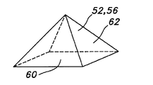
도 4a는 본 발명에 따른 스텐트(24)를 도시한다. 스텐트(24)는 제 1 비외상성 단부(34)와 반대측의 제 2 비외상성 단부(38)를 포함할 수 있다. 제 1 비외상성 단부는 필라멘트(20)의 전장의 중간부에서 필라멘트(20)를 굽혀서 굴곡부(36)를 형성함에 의해 형성될 수 있다. 반대측의 제 2 비외상성 단부(38)는 필라멘트(20)를 폐루프(39) 형태로 굽힘으로써 형성될 수 있다. 폐루프(39)를 형성하는 필라멘트(20)는 용접부(41)에 의해 서로 고정될 수 있다. 본 발명의 스텐트(24)는 스텐트 필라멘트(20)를 결합하는데 용접부(41)를 사용하는 것에 한정되지 않고, 하이포튜브(hypotube)의 사용 같은 그 외의 기계적 수단, 필라멘트의 비틀기 또는 묶기 등을 적절히 사용할 수 있다. 본 발명의 스텐트(24)는 또한 하나 이상의 외측으로 벌어지거나 확장된 부분(40)을 포함할 수 있다. 이런 경우에, 확개부의 직경은 스텐트(24)의 종방향 확대부(42)의 직경보다 크다. 스텐트(24)의 종방향 확대부(42)는 실질적으로 일정한 직경을 포함한 일정한 직경을 가질 수 있다. 이런 스텐트 구조들은 한정되지 않으며, 본 발명의 시스템, 장치 및 방법으로 그 외의 스텐트 구조들이 달성될 수 있다. 예를 들어, 스텐트(24)는 양단부(34, 38)에서 외측으로 확개된 부분을 포함할 수 있으며, 스텐트(24)의 종방향 확대부(42) 대신에 또는 동시에 테이퍼형 구조를 가질 수 있다.4A shows a
또한, 확장부(40) 및 종방향 확대부(42)를 포함한 스텐트(24) 전체에 걸친 꼬임각도(β)는 실질적으로 일정하다. 예를 들어, 도 4a에 도시한 바와 같이, 꼬임각도(β)는 약 110°±3°, 바람직하게는 약 110°±1°이다. 종래기술의 스텐트는 전형적으로 스텐트의 확개부 또는 확장부 같은 스텐트 천이영역에서 ±10°이상의 변경을 갖는다. 그러나 이런 변경은 반경방향 확장력, 반경방향 압축력 또는 전개력 같은 스텐트 성능에서의 바람직하지 못한 가변성을 나타낸다. 본 발명은 특히 장력이 가해지거나 일정한 힘의 꼬임 캐리어(14)(도 22의 설명과 함께 이하에서 더욱 상세히 설명함), 일정한 힘의 보빈 캐리어(110)(도 24의 설명과 함께 이하에서 더욱 상세히 설명함), 융기 돌기(52, 56, (선택에 따라서는) 70)를 갖는 꼬임 맨드렐(22)(도 5-도 16b의 설명과 함께 이하에서 더욱 상세히 설명함), 및/또는 맨드렐(22)상의 스텐트 필라멘트지지 고정 돌기(48)(도 6, 도 14 및 도 15의 설명과 함께 이하에서 상세히 설명함)를 사용함으로써 이런 바람직하지 못한 변화를 회피한다.In addition, the twist angle? Over the
도 4a의 스텐트(24)의 하나는 아래에 하나는 위에 있는 꼬임 구조는 도 4b에 분해도로서 도시되어 있다. 도 4b에 도시한 바와 같이, 필라멘트(20)들은 1/1 교차점을 갖는 꼬임 패턴, 즉 하나는 아래에 하나는 위에 있는 패턴으로 교대로 배치된다. 그러나 스텐트(24)는 여기에 제한되지 않는다. 도 4c에 도시한 바와 같이, 스텐트(24)는 두 개가 아래에 두 개가 위에 있는 패턴으로 꼬아진 필라멘트(20)를 포함할 수 있다. 기술적으로 공지된 그 외의 꼬임 패턴도 적절히 사용될 수 있다. 또한, 도 4d에 예시한 바와 같이, 스텐트(24)는 한 쌍의 필라멘트(20')를 하나는 아래에 하나는 위에 있는 패턴으로 사용함으로써 꼬아질 수 있다. 필라멘트(20')는 서로 동일하거나 다를 수 있으며, 즉 서로 동일하거나 다른 치수, 형상 및/또는 구조 재료를 가질 수 있다. 또한, 필라멘트(20')는 예를 들어 두 개는 아래에 두 개는 위에 있는 패턴 같은 그 외의 꼬임 패턴으로 적절히 꼬아질 수 있지만 여기에 한정되는 것은 아니다. 바람직하게는, 꼬아진 필라멘트(20, 20')는 비상호결합 방식으로 꼬임 패턴으로 서로 결합한다. 이런 비상호결합 방식의 꼬임 패턴은 필요에 따라서 꼬아진 필라멘트(20, 20')의 교차점에서 상호 비틀림, 상호 루프형성, 상호 결합 등을 제외한다. 필요에 따라서 꼬아지거나 직조된(woven) 필라멘트(20, 20')들은 상호 결합 방식으로 꼬아지거나 직조될 수 있다.One of the
바람직하게는 필라멘트(20)는 어떤 적절한 이식 가능한 재료로도 만들어지는데, 이 재료에는 니티놀(nitinol), 스테인레스 스틸, Elgiloy(R)같은 코발트계 합금, 백금, 금, 티타늄, 탄탈륨, 니오븀, 폴리머 재료 및 그 조합이 포함되지만 여기에 제한되지 않는다. 유용한 폴리머 재료에는 예를 들어 폴리에틸렌 테레프탈레이트(PET)폴리에스테르 같은 폴리에스테르류, 폴리프로필렌류, 폴리에틸렌류, 폴리우레탄류, 폴리올레핀류, 폴리비닐류, 폴리메틸아세테이트류, 폴리아미드류, 나프탈란 디카르복실렌 유도체류, 천연실크, 폴리비닐 클로라이드, 팽창 폴리테트라플루오로에틸렌(ePTFE)을 포함한 폴리테트라플루오로에틸렌, 불소화 에틸렌 프로필렌 코폴리머, 폴리비닐 아세테이트, 폴리스티렌, 폴리(에틸렌 테레프탈레이트), 폴리에틸렌 나프탈레이트, 폴리부틸렌 나프탈레이트, 폴리트리메틸렌 나프탈레이트 및 트리에틸렌디올 나프탈레이트 같은 나프탈렌 디카르복실레이트 유도체, 폴리우레탄, 폴리우레아, 실리콘 고무류, 폴리아미드류, 폴리카보네이트류, 폴리알데히드류, 천연고무류, 폴리에스테르 코폴리머류, 스티렌-부타디엔 코폴리머류, 완전 또는 부분 할로겐화 폴리에테르 같은 폴리에테르류, 및 코폴리머류와 그 조합이 포함된다. 또한 폴리머 스텐트 재료의 유용하고 비제한적인 예로는 폴리(L-락티드)(PLLA), 폴리(D,L-락티드)(PLA), 폴리(글리콜리드)(PGA), 폴리(L-락티드-코-D,L-락티드)(PLLA/PLA), 폴리(L-락티드-코-클리콜리드)(PLLA/PGA), 폴리(D,L-락티드-코-글리콜리드)(PLA/PGA), 폴리(글리콜리드-코-트리메틸렌 카보네이트)(PGA/PTMC), 폴리디옥사논(PDS), 폴리카프로락톤(PCL), 폴리히드록시부티레이트(PHBT), 폴리(포스파젠)폴리(D,L-락티드-코-카프로락톤)(PLA/PCL), 폴리(글리콜리드-코-카프로락톤)(PGA/PCL), 폴리(포스페이트 에스테르) 등이 포함된다. 폴리머 재료로 만들어진 와이어는 또한 폴리머 재료에 합체될 수 있는 금속계 분말, 입자 또는 페이스트 같은 방사선비투과성 재료를 포함할 수 있다. 예를 들어 방사선비투과성 재료는 폴리머 와이어를 구성하는 폴리머 조성물과 혼합된 후에 여기서 설명하는 스텐트로 만들어질 수 있다. 다른 방법으로서, 방사선비투과성 재료는 금속이나 폴리머 스텐트의 표면에 적용될 수 있다. 어느 실시형태에서라도 몇 가지 예를 들면 제한 없이 티타늄, 비스무스, 바륨 및 바륨 설페이트 같은 그 염, 탄탈륨, 텅스텐, 금, 백금 및 티타늄을 포함한 다양한 방사선비투과성 재료 및 그 염 및 유도체를 사용할 수 있다. 추가의 유용한 방사선비투과성 재료는 미합중국 특허 제 6,626,936호에서 찾을 수 있는데, 이 특허는 여기서 언급함으로써 그 전체를 인용한다. 방사선비투과성 재료로서 유용한 금속 착체도 생각할 수 있다. 스텐트는 원하는 최종 생성물 및 용도에 따라서 와이어를 따라서 원하는 부위가 방사선비투과성으로 선택적으로 만들어지거나 완전히 방사선비투과성으로 만들어질 수 있다. 또한, 필라멘트(20)는 탄탈륨, 금, 백금, 이리듐 도는 그 조합으로 된 내측 코어와 니티놀로 된 외측부재 또는 외층을 가져서 방사선비투과성 또는 가시성을 향상시키기 위한 복합 와이어를 제공할 수 있다. 바람직하게는 내측 코어는 백금이고 외층은 니티놀이다. 보다 바람직하게는 백금 내측 코어는 전체 단면적 퍼센트를 기준으로 와이어의 적어도 약 10%를 나타낸다. 또한 니티놀을 마르텐사이트상 및 오스테나이트상에서 가열, 성형 및 냉각하는 것 같은 형상기억 처리되지 않은 니티놀도 외층으로서 유용하다. 이런 복합와이어의 추가의 상세 내용은 미합중국 특허출원공보 제 2002/0035396 A1호에서 찾을 수 있는데, 여기서는 그 내용을 언급함으로써 인용한다. 바람직하게는 필라멘트(20)는 니티놀로 만들어지거나 또는 백금 중심 코어 및 니티놀 외층을 갖는 복합 와이어로 만들어질 수 있다.The
도 5는 본 발명에 따른 꼬임 맨드렐(22)의 측면도다. 꼬임 맨드렐(22)은 일반적으로 스테인레스 스틸 같은 금속의 관형, 즉 원위단부(꼬임기(10)에 배치되었을 때 노치기어(12)의 원(26)에서 멀리 위치) 및 반대측의 근위단부(46)(꼬임기(10)에 배치되었을 때 노치기어(12)의 원(26)에 근접하여 위치)를 갖는 원통형 부재이다. 원위단부(44)는 고정 돌기(48)를 포함하는데, 이는 후술하는 바와 같이 꼬임을 개시하기 전에 스텐트 필라멘트(20)를 결합시키는데 유용하다. 원위단부(44)는 원위부(50)를 더 포함하는데, 이는 맨드렐(22)의 종방향 부분(54)보다 큰 직경을 갖는다. 필라멘트(20)를 꼰 후에 원위 맨드렐부(50)는 확개 스텐트부(40)를 형성하며, 종방향 맨드렐부(54)는 종방향 확대 스텐트부(42)를 형성한다. 원위 맨드렐부(50) 및 종방향 맨드렐부(54)는 둘 다 각각 융기된 맨드렐 돌기(52, 56)를 포함할 수 있다. 후술하는 바와 같이, 융기된 맨드렐 돌기(52, 56)는 꼬임 중에 필라멘트(20)를 수용하는 가이드를 형성하는데 유용하다. 대직경부는 확개부, 단차부 등을 포함할 수 있다. 또한, 대직경부는 맨드렐(22)의 길이를 따라서 어디에라도 배치될 수 있다. 또한, 맨드렐(22)은 서로 동일하거나 다를 수 있는 다수의 대직경부를 가질 수 있다.5 is a side view of a
그러나 본 발명은 이중 크기 또는 확개형 맨드렐의 사용에 한정되지 않는다. 예를 들어, 도 6에 도시한 바와 같이, 꼬임기(22')는 실질적으로 일정한 직경의 스텐트(24)에 유용한 실질적으로 일정한 직경의 맨드렐이 될 수 있다. 맨드렐(22, 22')의 도시된 형상들은 제한되지 않으며 이중 확개형이나 확장형 맨드렐, 테이퍼형 맨드렐 등 같은 그 외의 형상의 맨드렐도 적절히 사용할 수 있다. 또한, 융기된 맨드렐 돌기(52, 56)는 꼬임 맨드렐(22)의 전체 꼬임 길이 및/또는 원주를 따라서 제공될 필요는 없다. 제조할 스텐트(24)의 특성에 따라서 꼬임 맨드렐(22)의 선택된 부분에 융기 맨드렐 돌기(52, 56)를 제거하거나 부분적으로 제거할 수 있다.However, the present invention is not limited to the use of double-size or bored mandrels. For example, as shown in FIG. 6, the twist 22 'may be a mandrel of substantially constant diameter useful in a substantially
도 7은 융기된 맨드렐 돌기(52, 56)를 더욱 도시하는 맨드렐(22)의 일부의 분해도다. 융기된 맨드렐 돌기(52, 56)는 인접하거나 나란하게 배치된 융기된 맨드렐 돌기(52, 56)들이 꼬임 중에 스텐트 필라멘트(20)를 수용하기 위한 가이드 또는 채널(58)을 형성하도록 맨드렐(22) 위에 규칙적인 패턴으로 배열된다. 도 8 - 도 10은 본 발명의 융기된 맨드렐 돌기(52, 56)를 더욱 상세히 보여준다. 도 8에 도시한 바와 같이, 융기된 맨드렐 돌기(52, 56)는 정사각형 또는 직사각형 저면(60) 및 4개의 삼각형 측면을 갖는 정사각형 또는 직사각형 피라미드의 형상이다. 도 9에 도시한 바와 같이, 융기된 맨드렐 돌기(52, 56)는 끝이 잘라진 상단부(64)를 가질 수 있다. 상단부(64)는 필요에 따라서 약간 둥글게 될 수 있다(도시하지 않음). 절두형 및/또는 둥근형 상단부(64)는 스텐트(24)를 맨드렐(22)로부터 제거하기 쉽게 하는데 유용하다. 예를 들어, 스텐트(24)를 맨드렐(22)로부터 제거하기 위해서 스텐트(24)는 종방향으로 압축되어 스텐트의 직경을 증대시킬 수 있다. 이 때 스텐트 필라멘트(20)는 절두형 및/또는 둥근형 상단부(64) 위에서 없어지므로 스텐트(24)를 맨드렐(22)로부터 해제할 수 있다. 예를 들어 스텐트 필라멘트(20)의 꼬임각도 및/또는 융기된 맨드렐 돌기(52, 56)의 높이에 따라서, 융기된 맨드렐 돌기(52, 56)는 끝이 잘라져서 맨드렐(22)의 절두형 및/또는 둥근형 상단부(64)를 형성할 수 있다. 절두형 및/또는 둥근형 상단부(64)는 또한 스텐트 필라멘트(20)를 맨드렐(22)의 가이드 또는 채널(58) 속으로 안내하는데 유용할 수 있다. 또한, 도 10에 도시한 바와 같이, 융기된 맨드렐 돌기(52, 56)는 맨드렐(22)의 가이드 또는 채널(58)을 더욱 한정하기 위해 정사각형 또는 직사각형 기부(66)를 더 포함할 수 있다. 융기된 맨드렐 돌기(52, 56)의 이런 특징부들은 맨드렐 가이드 또는 채널(58)을 형성하는데 유용하므로 꼬임 중에 확개부 또는 테이퍼부 같은 맨드렐(22)의 치수 변화부에 대한 스텐트 필라멘트(20)의 정확한 배치를 포함한 스텐트 필라멘트(20)의 정확한 배치가 이루어진다. 그러나 본 발명은 정사각형 또는 직사각형 피라미드 형상의 융기된 맨드렐 돌기(52, 56)의 사용에 한정되는 것은 아니며, 그 외의 적절한 형상의 돌기도 적절히 사용할 수 있다. 예를 들어, 제거 가능한 핀이나 돌기를 포함한 핀이나 돌기를 적절히 사용할 수 있다. 융기된 맨드렐 돌기(52, 56)는 레이저 절단, 기계 절단, 화학적 엣칭 등 같이 맨드렐의 일부를 절단하거나 엣칭하여 제거함으로써 형성될 수 있다. 또한, 가이드 또는 채널(58)은 맨드렐의 홈으로서 형성될 수 있다. 또한, 채널(58)을 형성하는 융기된 맨드렐 돌기(52, 56)는 꼬임기 자체에 착탈 가능하게 고정될 수 있는 칼라 또는 슬리브 상에 있을 수 있다.7 is an exploded view of a portion of the
도 11은 꼬임 맨드렐(22)의 원위단부(44)의 일부의 분해도다. 고정 돌기(48)들은 융기된 탭(48')으로서 도시되어 있다. 융기된 탭(48')은 일반적으로 맨드렐(22)상의 형상 및 뾰족한 면을 제거함으로써 스텐트 필라멘트(20)의 고정의 용이성 및 안정성을 위해 둥근면(49)을 갖는다. 도 12에 도시한 바와 같이, 융기된 탭(48')은 융기된 탭(48')의 하측부(51)를 중심으로 스텐트 필라멘트(22)를 굽히는데 유용하다. 융기된 탭(48')의 하측부(51)는 스텐트 필라멘트 와이어(20)를 고정하기 위해 둥근면(49)으로부터 오목하게 되어있다. 또한, 융기된 탭(48')의 하측부(51)는 스텐트(24)의 원위단부(34)의 굴곡부(36)의 형상이 융기된 탭(48')의 하측부(51)의 형상과 일치하도록 구성될 수 있다. 그러나 본 발명은 고정 돌기(48)로서 전술한 융기된 탭(48')의 하측부(51)에 한정되지 않으며, 후술하는 바와 같이 고정 돌기(48)에 대한 다른 구조도 적절히 사용할 수 있다. 또한, 본 발명은 하나의 융기된 탭(48') 주위의 하나의 스텐트 필라멘트(20)의 고정에 한정되지 않는다. 예를 들어, 필요에 따라서 서로 다른 재료 및/또는 사양을 포함하는 서로 다르거나 동일할 수 있는 두 개 이상의 스텐트 필라멘트(20)가 하나의 융기된 탭(48') 주위에 고정된 후 본 발명의 기술에 따라서 꼬아질 수 있다.Figure 11 is an exploded view of a portion of the
도 13은 스텐트 필라멘트(20)의 중간부가 융기된 돌기(48')에 고정된 꼬임 맨드렐(22)을 도시한다. 또한, 스텐트 필라멘트(20)는 나란하게 배치된 융기돌기(52, 56) 사이에 형성된 맨드렐(22)의 채널(58) 내에 배치된다. 도 14는 맨드렐(20) 위에 꼬아지는 스텐트 필라멘트(20)를 도시한다. 또한 꼬임 맨드렐(22)의 일단부 예를 들어 근위단부(46)는 슬리브(47)에 의해 꼬임기(10)의 맨드렐(22')에 해제 가능하게 고정될 수 있다. 꼬임 맨드렐(22)을 꼬임기(10)의 맨드렐(22')에 고정하기 위해 그 외의 배치구조도 적절히 사용할 수 있다.13 shows a
도 15는 꼬임 맨드렐(22)의 근위단부(46)의 분해도다. 꼬임 맨드렐(22)의 근위단부는 스텐트(24)의 폐루프(39)를 형성하는데 유용한 돌기(45)들을 포함할 수 있다. 이런 폐루프는 돌기(45) 주위로 필라멘트(20)를 굽힘으로써 형성될 수 있다(도시하지 않음). 이런 폐루프(39)를 형성하는 상세내용은 린나(Leanna) 등의 미합중국 특허출원공보 제 2005/0049682 A1호; 클럭(Clerc) 등의 미합중국 특허출원공보 제 2005/0256563 A1호; 및 노턴(Norton) 등의 미합중국 특허출원공보 제 2006/0116752 A1호에서 찾을 수 있는데, 여기서는 그 내용들을 언급함으로써 인용한다.Figure 15 is a breakaway of the
도 5 - 도 15의 꼬임 맨드렐(22)은 단일 스텐트를 제조하는데 유용한 것으로 도시되어 있다. 그러나 본 발명의 꼬임 맨드렐(22)은 여기에 한정되지 않는다. 예를 들어 각각 스텐트부의 꼬임을 개시하기 위한 고정 돌기(48); 특정 구간 내에 스텐트 필라멘트(20)를 수용하여 조정하기 위한 채널(58); 및 본 발명의 비외상성 스텐트(24)를 마무리하는 돌기(45)를 갖는 여러 맨드렐 영역을 제공함으로써 단일 맨드렐(22) 상에 몇 개의 스텐트(24)가 제조될 수 있다. 몇 개 또는 다수, 즉 두 개 이상의 스텐트(24)는 서로 동일하거나 또는 스텐트 직경 및 스텐트 길이를 포함한 여러 스텐트 구조를 가질 수 있다. 다시 말해서, 본 발명의 기술 및 장치들은 한 개 또는 복수의 고도의 맞춤형 스텐트를 제조할 수 있게 한다. 이런 스텐트의 맞춤형 특징은 비외상성 스텐트 단부형상을 포함한 스텐트 길이, 스텐트 직경, 스텐트 굴곡, 스텐트 형상의 맞춤을 포함하지만 여기에 한정되지 않는다.The
도 16a 및 도 16b는 본 발명의 꼬임 맨드렐(22)의 일부의 부분 분해도다. 도 16a에 도시한 바와 같이, 원위 맨드렐부(50)는 종방향 맨드렐부(54)의 직경보다 큰 직경을 갖는다. 원위 맨드렐부(50)와 종방향 맨드렐부(54) 사이의 천이부(53)는 맨드렐(22) 직경이 단순히 감소한 부분이다. 도 16b에 도시한 바와 같이, 큰 원위부(50)와 작은 종방향 맨드렐부(54) 사이에는 천이영역(68)이 배치된다. 천이영역(68)은 바람직하게는 두 개의 직경 사이의 경사진 원추형 영역이다. 천이영역(68)은 전술한 형상의 융기돌기(52, 56)와 유사한 융기된 맨드렐 돌기(70)를 더 포함할 수 있다.16A and 16B are partial exploded views of a portion of the
이상 본 발명의 특징들을 융기돌기(52, 56)를 갖는 맨드렐(22, 22')을 사용하는 것으로 설명하였지만, 본 발명은 이에 한정되지 않는다. 예를 들어, 도 17에 도시한 바와 같이 바람직한 경우에는 전술한 융기돌기(52, 56)가 없거나 실질적으로 없는 꼬임 맨드렐(22")을 적절히 사용할 수 있다. 이런 맨드렐(22")은 역시 그 원위단부(44)에 전술한 고정돌기(48)를 포함하고 그 근위단부(46)에 돌기(45)(도시하지 않음)를 포함할 수 있다.Although the features of the present invention have been described as using the
도 18 - 도 21은 꼬임 맨드렐(22)의 원위단부(44)에서 스텐트 필라멘트(20)를 고정하기 위한 고정돌기(48)의 다른 실시형태를 예시한다. 이들 실시형태들은 꼬임 맨드렐(22)의 원위단부(44)에 해제 가능하게 고정될 수 있거나 또는 경우에 따라서는 전술한 융기된 탭(48') 같은 꼬임 맨드렐(22)의 원위단부(44)와 일체적으로 형성될 수 있지만 여기에 한정되는 것은 아니다. 도 18 및 도 19는 꼬임 맨드렐(22)의 원위단부(44)에 스텐트 필라멘트(20)를 고정하기 위한 마차바퀴 배치구조부(72)를 도시한다. 이 마차바퀴(부72)는 핀(74)을 포함할 수 있는데, 이 핀 주위로 스텐트 필라멘트(20)들이 배치될 수 있다. 스텐트 필라멘트(20)는 핀(74)의 내측부(76) 주위로 배치될 수 있지만 필요한 경우에 스텐트 필라멘트(20)는 외측핀부(77) 주위로 배치될 수 있다. 마차바퀴부(72)는 파형표면(78(을 더 포함할 수 있다. 파형 표면(78)은 마차바퀴(72) 내에 스텐트 필라멘트(20)를 위치시키는데 유용하다. 또한, 파형 표면(78)의 형상은 스텐트(24)의 굴곡부(36)의 원하는 각도와 일치하도록 변경될 수 있다.FIGS. 18-21 illustrate another embodiment of a securing
도 20은 원위단부에 구멍(80)을 갖는 맨드렐(22")을 도시한다. 구멍(80) 속에는 거기에 스텐트 필라멘트(20)(도시하지 않음)를 고정하기 위해 스크류, 핀, 탭, 멈춤쇠 등(도시하지 않음)이 삽입될 수 있다. 도 21에 도시한 바와 같이, 도 20의 실시형태와 함께 캡(82)이 사용될 수 있다. 캡(82)은 도 20과 함께 설명한 핀이나 스크류를 수용하는 다수의 반원형 노치(84)를 가질 수 있다. 캡(82)은 스텐트(24)의 굴곡부(36)의 배향, 구조 및/또는 각도를 설정하는데 유용한 각도면 또는 경사면(84)을 더 포함할 수 있다. 스텐트 필라멘트(20)를 고정하기 위한 돌기의 본 실시형태는 맨드렐(22")과 일체적으로 형성되는 것으로 도시하였지만, 구멍(80)은 그 외의 설명한 맨드렐(22, 22')중의 어느 것에도 일체적으로 형성되거나, 또는 꼬임 맨드렐(22, 22', 22") 중의 어느 것에도 해제 가능하게 고정될 수 있는 별개의 장치로서 형성될 수 있다.Figure 20 shows a
도 22는 본 발명의 장력이 가해지거나 일정한 힘의 꼬임 캐리어(14)의 개략도다. 일정한 힘의 캐리어(14)는 휘일(90, 92, 94, 96) 및 스프링(98)을 고정하기 위한 프레임(88)을 포함할 수 있다. 신축형 캐리어 필라멘트(16)는 휘일(92) 주위에 견고히 감겨진 일단부를 가질 수 있다. 신축형 캐리어 필라멘트(16)는 도시한 바와 같이 휘일(94, 96)을 통해 일정한 힘의 캐리어(14)를 나올 수 있다. 휘일(94, 96)은 신축형 캐리어 필라멘트(16)를 꼬임 구역(32)쪽으로 안내하는데 유용하다. 스프링(98)은 신축형 캐리어 필라멘트(16)에 어느 정도 일정한 장력을 제공하기 위해 휘일(90)로부터 휘일(92)에 일정한 힘을 부여한다. 신축형 캐리어 필라멘트(16) 자체는 스프링(98)에 의해 가해진 장력과 연결되도록 휘일(92) 주위로 감겨질 수 있다. 또한, 스텐트(24)가 꼬아짐에 따라서, 신축형 캐리어 필라멘트(16)가 휘일(92)로부터 풀려서 스텐트 필라멘트(20)의 움직임을 꼬임 구역(32) 내에 수용할 수 있다. 일정한 힘의 캐리어(14)의 프레임(88)의 바닥부(89)는 도 1 - 도 2에 개략적으로 도시한 바와 같이 노치기어(14)에 해제 가능하게 고정될 수 있다. 도 22의 일정한 힘의 캐리어(14)는 스텐트 형성 필라멘트(20)가 감겨진 보빈을 포함하지 않는다. 다시 말해서, 도 22의 일정한 힘의 캐리어(14)는 스텐트 형성 필라멘트(20)를 배제하고 신축형 캐리어 필라멘트(16)를 포함한다.22 is a schematic view of a
일정한 힘 또는 장력이 가해진 꼬임 캐리어(14)는 개별적인 스텐트 형성 필라멘트(20)의 길이부들을 꼬는데 유용하다. 일정한 힘 도는 장력이 가해진 꼬임 캐리어(14)를 사용함으로써 스텐트 형성 필라멘트(20)의 전부 또는 실질적으로 전부가 꼬임 구역(32) 내에 직접 배치된다. 따라서, 스텐트 형성 필라멘트(20)상의 일정한 장력 또는 실질적으로 일정한 장력이 조절되어 꼬임 구역(32) 내에 직접 유지된다. 종래기술의 꼬임 기술들은 꼬임 구역 내의 필라멘트 장력을 이렇게 조절하여 꼬임 각도 및 스텐트 셀 사이즈를 보다 크게 변경시킬 수 있는 것이 없다.The
도 23은 도 1과 함께 앞에서 설명한 클립(18)의 일 실시형태의 개략도다. 클립(18)은 신속해제형 클립으로서 도시되어있지만, 어떤 클립이나 고정 기구를 적절히 사용해서도 스텐트 형성 필라멘트(20)를 신축형 캐리어 필라멘트(16)에 고정할 수 있다. 신축형 캐리어 필라멘트(16)는 클립(18)에 해제 가능하게 고정되도록 견고하게 배치될 수 있다. 스텐트 형성 필라멘트(20)는 바람직하게는 클립(18)에 해제 가능하게 고정된다. 클립(18)의 보디(104)와 노브(102) 사이에는 스프링(100)이 사용될 수 있다. 스프링(100)의 힘에 대항하여 노브(102)를 클립보디(104) 쪽으로 움직이면 클립(18)의 보디(104) 내에서 필라멘트 결합부(도시하지 않음)를 움직임으로써 클립(18)으로부터 스텐트 형성요소(20)를 해제하게 된다.Figure 23 is a schematic view of one embodiment of the
도 24는 본 발명에 따라서 사용될 수 있는 일정한 힘의 보빈 캐리어(110)의 다른 실시형태를 개략적으로 도시한다. 일정한 힘의 보빈 캐리어(110)는 스텐트 형성 필라멘트(20)가 감기는 보빈(114)을 포함한다. 일정한 힘의 보빈 캐리어(110)는 스텐트 형성 필라멘트(20)에 일정한 장력을 제공하는 래치 스프링(116)을 포함한다. 래치 스프링(116)은 전형적으로 스텐트 형성 필라멘트(20)를 안내하기 위해 아이렛(eyelet)(도시하지 않음) 또는 작은 휘일을 포함한다. 래치 스프링(116)은 궤도로 표시한 것처럼 보빈(114)으로부터 멀리 움직여서 스텐트 형성 필라멘트(20)에 장력을 제공할 수 있다. 스텐트 형성 필라멘트(20)는 제 1 휘일(118) 및 제 2 휘일(120) 주위로 이동한다. 스텐트 형성 와이어(20)는 일정한 힘의 보빈 캐리어(110)를 나와서 본 발명에 따라서 스텐트(24)를 꼬기 위한 꼬임 구역(32) 쪽으로 간다. 전형적으로, 스텐트 형성 필라멘트(20)는 일부가 한 보빈(114)으로부터 풀린 다음에 풀린 부분이 다른 일정한 힘의 보빈 캐리어(110)(도시하지 않음)의 다른 보빈(114)에 다시 감긴다. 일정한 힘의 보빈 캐리어(110)가 노치기어(12)에 고정된 후, 스텐트 형성 필라멘트(20)의 중간부가 꼬임 맨드렐(22)의 고정 돌기(48)에 결합되어 본 발명에 따라서 스텐트를 꼴 수 있다. 그러나 다른 실시형태는 스텐트 필라멘트가 보빈(114)에 다시 감겨야 하므로 시간이 더 많이 소비될 수 있다.Figure 24 schematically illustrates another embodiment of a constant
원위 고정돌기(48) 및 꼬임 채널(58)을 갖는 꼬임 맨드렐(22, 22')과 함께 일정한 힘의 보빈 캐리어(110)를 사용하면 본 발명의 스텐트를 꼬는데 적절한 장력을 조절할 수 있다. 그러나 일정한 힘의 꼬임 캐리어(110)는 장력이 가해진 꼬임 캐리어(14)를 사용하는 것과 비교하여 더 큰 필라멘트(20)의 길이부를 필요로 할 수 있다. 이처럼 필라멘트(20)의 보다 큰 부분이 보빈 캐리어(110)의 사용으로 꼬임 구역(32)의 외부에 있어서 꼬임 구역(32) 내의 필라멘트(20)상의 장력의 직접 조절을 적게 할 수 있다.The use of a constant
또 다른 실시형태에 있어서는 일정한 힘의 캐리어(14) 및 일정한 힘의 보빈 캐리어(110)의 조합을 사용할 수 있는데, 이 경우 스텐트 필라멘트(20)를 다른 보빈(114)에 다시 감는 대신에 보빈(114)에서 나오는 스텐트 필라멘트 단부가 클립(18)을 통해 일정한 힘의 캐리어(14)에 해제 가능하게 고정될 수 있다.In another embodiment, a combination of a
바람직하게는 맨드렐(22) 위에 스텐트(24)를 꼬는 동안에 필라멘트(16, 20)에 조절된 장력을 제공하도록 일정한 힘의 캐리어(14) 및 일정한 힘의 보빈 캐리어(110)를 본 발명의 상기 다른 실시형태와 함께 구성 및 제어할 수 있다. 유용한 장력에는 약 1/8 또는 0.125파운드의 힘(약 0.5뉴튼) 내지 약 10파운드의 힘(약 45뉴튼)의 실질적으로 일정한 인장력이 포함된다. 바람직하게는 이 인장력은 약 1/4 또는 0.25파운드의 힘(약 1뉴튼) 내지 약 10파운드의 힘(약 22뉴튼)이다. 바람직하게는 인장력은 약 1/2 또는 0.5파운드의 힘(약 2뉴튼) 내지 약 3파운드의 힘(약 13뉴튼)이다. 일반적으로 필라멘트(20)의 직경이 커질수록 더 큰 인장력이 적용될 것이다. 꼬임 및 후속 처리 단계 중에 필라멘트(20)를 맨드렐(22) 상에 견고하게 유지하는데는 최소의 힘 레벨이 필요하다. 너무 많은 힘이 가해지는 경우, 필라멘트(20)가 맨드렐(22) 상에서 늘어나거나 변형될 수 있으며, 특히 스텐트가 맨드렐(22) 상에 있는 동안 열처리되는 경우에 그런데, 이는 필라멘트 또는 와이어의 넥킹(necking)이라고 부른다. 이런 넥킹은 바람직하지 못한데 이는 필라멘트 또는 와이어를 약하게 하여 아마도 필라멘트 또는 와이어의 파손으로 이어지기 때문이다. 이런 전술한 인장력은 바람직하게는 금속 필라멘트(20)를 꼬는데 유용하다. 비금속, 예를 들어 폴리머 필라멘트(20)를 꼬아서 스텐트(24)를 형성하는 경우, 적용되는 장력은 금속 필라멘트(20)에 대한 장력보다 작을 수 있다. 예를 들어, 폴리머 필라멘트(20)를 꼬는데는 약 0.5파운드의 힘(약 2뉴튼) 내지 약 1파운드의 힘(약 2뉴튼)의 인장력이 유용하다.A
도 25는 본 발명의 스텐트(24)를 꼬는 방법을 도시한다. 단계(200)에서 다수의 기다란 스텐트 필라멘트를 제공한다. 각각의 필라멘트는 서로 반대측의 단부 및 이 양측 단부 사이의 중간부를 갖는다. 단계(210)에서, 다수의 장력이 가해진 캐리어를 제공한다. 단계(220)에서는 서로 반대측의 근위단부와 원위단부를 갖는 꼬임 맨드렐을 제공한다. 꼬임 맨드렐은 꼬임 맨드렐의 원위단부에서 다수의 원주방향으로 이격된 고정돌기를 포함할 수 있으며, 선택에 따라서는 꼬임 중에 스텐트 필라멘트를 수용하기 위한 다수의 홈 또는 채널을 포함할 수 있다. 단계(230)에서 한 필라멘트의 중간부는 고정 돌기 중의 한 돌기에 견고하게 배치된다. 단계(240)에서 한 필라멘트의 양측 단부 중의 하나는 한 필라멘트를 장력이 가해진 하나의 꼬임 캐리어에 감는 것 없이 장력이 가해진 꼬임 캐리어중의 하나에 고정된다. 단계(250)에서 한 필라멘트의 다른 반대측 단부는 한 필라멘트를 제 2의 장력 캐리어에 감는 것 없이 다른 제 2의 장력 캐리어에 고정된다. 단계(260)에서는 필라멘트의 중간부 전부가 고정 돌기중의 다른 돌기에 견고하게 배치될 때까지 그리고 다수의 필라멘트의 각 단부가 장력 캐리어 중의 다른 캐리어에 고정될 때까지 단계(230)-(250)가 반복된다. 단계(270)에서, 장력이 가해진 캐리어들은 일반적인 원형의 구불구불한 동작으로 움직인다. 단계(280)에서 맨드렐은 장력 캐리어의 동작에 실질적으로 직각인 방향에 대하여 종방향으로 진행되어 필라멘트를 꼬아서 꼬아진 스텐트를 형성한다.25 illustrates a method of twisting the
본 실시형태의 방법은 장력이 가해진 꼬임 캐리어로부터 일정한 힘을 필라멘트에 적용하는 단계를 더 포함할 수 있는데, 여기서 일정한 장력은 약 0.25파운드의 힘(1.1뉴튼) 내지 약 5파운드의 힘(22.2뉴튼)이다. 또한, 고정 돌기의 개수는 필라멘트의 개수의 약 절반일 수 있지만, 어떠한 적절한 개수의 고정 돌기도 사용할 수 있다. 장력이 가해진 캐리어의 개수는 필라멘트의 개수의 약 두 배일 수 있지만 어떠한 적절한 개수의 장력 캐리어도 사용할 수 있다. 바람직하게는 필라멘트의 개수는 약 6개 내지 약 40개 이상일 수 있다. 이런 개수의 고정 돌기 및 장력 캐리어는 제한되는 것이 아니며, 어떠한 적절한 상대 개수의 고정 돌기 및 장력 캐리어도 사용할 수 있다. 예를 들어, 필라멘트(20)의 개수 및 유형은 다른 유형의 재료 및/또는 다른 개수의 필라멘트로 다른 스텐트 구간을 꼬는 것을 포함하는 스텐트의 꼬임 중에 증가 및/또는 감소될 수 있다.The method of the present embodiment may further comprise applying a constant force to the filament from a tensioned twisted carrier wherein the constant tension is from about 0.25 pounds of force (1.1 Newtons) to about 5 pounds of force (22.2 Newtons) to be. Also, the number of fixing projections may be about half the number of filaments, but any suitable number of fixing projections may be used. The number of tensioned carriers can be about twice the number of filaments, but any suitable number of tension carriers can be used. Preferably the number of filaments can be from about 6 to about 40 or more. This number of fixation protrusions and tension carriers is not limiting, and any suitable relative number of fixation protrusions and tension carriers may be used. For example, the number and type of
맨드렐은 다수의 홈 또는 채널을 포함할 수 있는데, 이 경우 필라멘트들은 단계(270) 내지 단계(280)의 꼬임 중에 홈 속에 배치된다. 필라멘트들은 꼬임 단계(270) 내지 (280) 중에 홈 내에 접선방향으로 배치될 수 있다. 바람직하게는 필라멘트가 맨드렐의 근위단부 근처의 맨드렐 부분까지 꼬아질 때까지 단계(270) 내지 (280)가 반복된다. 이 꼬임 방법은 필라멘트를 약 0.25파운드의 힘(1.1뉴튼) 내지 약 5파운드의 힘(22.2뉴튼)의 장력하에 유지하면서 필라멘트를 맨드렐의 그 부분에 고정하는 단계를 더 포함할 수 있다. 도한 스텐트는 열처리될 수 있다. 바람직하게는 스텐트 필라멘트의 열처리는 필라멘트가 맨드렐 상에 배치되어있는 동안 그리고 필라멘트가 장력하에 있는 동안에 실시될 수 있다.The mandrel may comprise a plurality of grooves or channels, in which case the filaments are placed in the grooves during the twist of
꼬임 맨드렐의 원위단부에 있는 고정 돌기들은 후크, 핀, 탭, 스크류 및 이들의 조합에서 선택될 수 있다. 고정 돌기들은 맨드렐에서 제거 가능할 수 있다. 꼬임 맨드렐의 원위단부에는 고정 돌기를 갖는 칼라가 더 배치될 수 있다.The locking protrusions at the distal end of the kinked mandrel may be selected from hooks, pins, tabs, screws and combinations thereof. The locking protrusions may be removable from the mandrel. At the distal end of the kink mandrel, a collar having locking protrusions may be further disposed.
또한 맨드렐은 제 1 직경을 갖는 제 1 부분과, 제 2 직경을 갖는 제 2 부분을 포함할 수 있는데, 여기서 제 1 직경은 제 2 직경과는 다르다. 맨드렐은 서로 다른 직경을 갖는 다수의 부분들을 포함할 수 있다. 또한, 맨드렐은 맨드렐의 전장을 따라서 심지어는 맨드렐의 원주를 따라서 또는 양자를 모두 따라서 연결될 수 있는 교체가능부분을 포함할 수 있다. 흠들은 제 1 부분 및 제 2 부분 전체에 걸쳐서 배치될 수 있다. 또한 상호 교차하는 꼬아진 필라멘트 사이의 꼬임 각도가 제 1 부분과 제 2 부분에서 실질적으로 동일하게 되도록 일정한 힘의 꼬임 캐리어로부터 필라멘트에 일정한 장력이 가해질 수 있다. 맨드렐은 제 1 부분과 제 2 부분 사이에 천이부분을 더 포함할 수 있다. 바람직하게는 꼬임 각도는 제 1 부분, 천이 부분 및 제 2 부분에서 실질적으로 동일하다. 그러나 본 발명은 여기에 한정되지 않으며, 꼬임 각도는 직선 스텐트 구간과 확개 구간, 확장 구간, 굴곡 구간 등 같은 비직선 스텐트 구간에 걸친 꼬임 각도의 변경을 포함한 어떠한 맞춤 값으로도 조절될 수 있다.The mandrel may also include a first portion having a first diameter and a second portion having a second diameter, wherein the first diameter is different from the second diameter. The mandrel may include a plurality of portions having different diameters. The mandrel may also include a replaceable portion that can be connected along the entire length of the mandrel, even along the circumference of the mandrel, or both together. The blemishes may be disposed throughout the first and second portions. A constant tension can also be applied to the filaments from a twisted carrier of constant force such that the twist angle between the mutually intersecting twisted filaments is substantially the same at the first and second portions. The mandrel may further include a transition portion between the first portion and the second portion. Preferably the twist angle is substantially the same at the first portion, the transition portion and the second portion. However, the present invention is not limited thereto, and the twist angle can be adjusted to any custom value including a change in twist angle over a non-linear stent section such as a straight stent section and a widening section, an extension section, a bending section,
필라멘트들은 금속 필라멘트, 폴리머 필라멘트, 및 그 조합에서 선택될 수 있다. 필라멘트들은 단일 가닥 또는 다수 가닥의 필라멘트일 수 있다. 다수 가닥의 필라멘트의 가닥들은 서로 다른 재료, 서로 다른 형상, 서로 다른 기계적 특성, 서로 다른 물리적 특성, 서로 다른 화학적 특성 등 같이 서로 다르거나 서로 동일할 수 있다. 바람직하게는 필라멘트들은 니티놀 필라멘트 또는 니티놀함유 필라멘트를 포함한 금속 필라멘트이다.Filaments can be selected from metal filaments, polymer filaments, and combinations thereof. The filaments may be single-stranded or multi-stranded filaments. Strands of filaments of multiple strands may be different or identical to each other, such as different materials, different shapes, different mechanical properties, different physical properties, different chemical properties, and the like. Preferably, the filaments are metal filaments comprising a nitinol filament or a nitinol containing filament.
도 26은 본 발명의 스텐트(24)를 꼬는 방법의 다른 실시형태를 도시한다. 단계(300)에서 다수의 기다란 필라멘트들을 제공하는데, 각 필라멘트는 서로 반대측의 단부와 이 반대측 양 단부 사이의 중간부분을 갖는다. 단계(310)에서는 다수의 꼬임 캐리어를 제공한다. 단계(320)에서 서로 반대측의 근위단부 및 원위단부를 갖는 꼬임 맨드렐을 제공한다. 꼬임 맨드렐은 원위단부에 다수의 원주방향으로 이격된 고정 돌기를 포함할 수 있으며, 선택에 따라서는 다수의 홈을 더 포함할 수 있다. 단계(330)에서 한 필라멘트의 중간부가 맨드렐의 원위단부에서 고정 돌기중의 한 돌기에 견고하게 배치된다. 단계(340)에서, 한 필라멘트의 서로 반대측 단부중의 한 단부가 하나의 꼬임 캐리어에 고정된다. 단계(350)에서 한 필라멘트의 다른 반대측 단부가 다른 제 2 꼬임 캐리어에 고정된다. 단계(360)에서는 필라멘트의 중간부분 전부가 고정 돌기중의 다른 돌기에 견고하게 배치될 때까지 그리고 다수의 필라멘트의 각 단부가 꼬임 캐리어 중의 다른 캐리어에 고정될 때까지 단계(330) 내지 (350)가 반복된다. 단계(370)에서 꼬임 캐리어는 일반적인 원형의 구불구불한 동작으로 움직인다. 단계(380)에서 맨드렐은 꼬임 캐리어의 동작에 실질적으로 직각인 방향으로 꼬임기에 대하여 종방향으로 진행하여 필라멘트를 꼬아서 꼬아진 스텐트를 형성하며, 그리고 선택에 따라서는 필라멘트의 꼬임 중에 일정한 장력, 예를 들어 약 0.25파운드의 힘(1.1뉴튼) 내지 약 5파운드의 힘(22.2뉴튼)이 꼬임 캐리어로부터 필라멘트에 가해진다.26 shows another embodiment of a method for twisting the
본 실시형태의 꼬임 캐리어는 일정한 힘의 캐리어일 수 있다. 필라멘트의 단부들은 필라멘트를 일정한 힘의 캐리어에 감는 것 없이 일정한 힘의 캐리어에 견고하게 배치될 수 있다. 다른 방법으로서 또는 추가적으로 꼬임 캐리어의 일부 또는 전부는 필라멘트의 일부가 감기는 보빈을 포함할 수 있다.The twisted carrier of this embodiment may be a carrier of constant force. The ends of the filament can be firmly disposed on a carrier of constant force without winding the filament over a carrier of constant force. Alternatively or additionally, part or all of the twisted carrier may include a bobbin around which a portion of the filament is wound.
이상 본 발명을 꼬임기의 사용을 통하여 설명하였지만, 본 발명의 특정 특징들은 손으로 꼬거나 손으로 직조하는 방법으로 스텐트를 형성하는데도 유용할 수 있다. 이런 경우에 꼬임 맨드렐은 종방향 길이를 따라서 추가의 탭, 핀 등을 더 포함할 수 있는데, 이들을 중심으로 꼬임 필라멘트의 장력이 얻어질 수 있다.Although the present invention has been described above with the use of a twist, certain features of the present invention may also be useful for forming a stent by hand twist or hand weaving. In this case, the twist mandrel may further include additional tabs, pins, etc. along its longitudinal length, and the tension of the twisted filament about these can be obtained.
본 발명의 스텐트(24)는 피막에 치료제를 포함할 수 있다. 본 발명의 스텐트(24)의 피막 속의 치료제는 비유전적(non-genetic) 치료제, 생체분자, 소분자 또는 세포 같은 어떠한 적절한 생물학적으로 허용되는 치료제도 될 수 있다.The
모범적인 비유전적 치료제로는 헤파린, 헤파린 유도체, 프로스타글란딘(미셀라 프로스타글란딘 E1(micellar prostagladin E1) 포함), 우로키나제, 및 PPack(덱스트로페닐알라닌 프롤린 알기닌 클로로메틸 케톤) 같은 항혈전제; 에녹사파린, 안지오펩틴, 시롤리무스(라파마이신), 타크로리무스, 에베로리무스, 조타로리무스, 바이오리무스, 평활근세포증식을 차단할 수 있는 단일클론성 항체 같은 항증식제; 덱사메타손, 로시글리타존, 프레드니솔론, 코르티코스테론, 부데소니드, 에스트로겐, 에스트라디올, 설파살라진, 아세틸살리실산, 미코페놀산, 및 메살라민 같은 항염증제; 파클리탁셀, 에포틸론, 클라드리빈, 5-플로오로우라실, 메토트렉세이트, 독소루비신, 다우노루비신, 시클로스포린, 시스플라틴, 빈블라스틴, 빈크리스틴, 에포틸론, 엔도스타틴, 트라피딜, 할로푸기논, 및 안지오스타틴 같은 항종양/항증식/항분열제; c-myc-oncogene의 안티센스 저해제 같은 항암제; 트리클로산, 세팔로스포린류, 아미노글리코시드류, 니트로푸란토인, 은이온, 화합물 또는 염 같은 항암제; 비스테로이드성 항염증제 같은 균막합성 저해제 및 에틸렌디아민테트라아세트산, O,O'-비스(2-아미노에틸)에틸렌글리콜-N,N,N',N'-테트라아세트산 및 그 혼합물 같은 킬레이트제; 키메라 항체 및 항체 단편을 포함하는 항체; 리도카인, 부피바카인, 및 로피바카인 같은 마취제; 산화질소; 린시도민, 몰시도민, L-알기닌, NO-탄수화물 부가물, 폴리머 또는 올리고머 NO 부가물 같은 산화질소(NO) 도너; D-Phe-Pro-Arg 클로로메틸 케톤, RGD 펩티드함유 화합물, 헤파린, 항트롬빈 항체를 포함하는 항트롬빈 화합물, 혈소판수용체길항제, 항혈소판수용체항체, 에녹사파린, 히루딘, 와파린 소듐, 디쿠마롤, 아스피린, 프로스타글란딘 저해제, 시로스타졸 및 틱항혈소판인자(tick antiplatelet factor) 같은 혈소판응집 저해제 같은 항응고제; 성장인자, 전사활성화인자(transcriptional activator) 및 병진운동 촉진제 같은 혈관세포 성장 촉진체; 성장인자 억제제, 성장인자수용체 항길제, 전사억제인자(transcriptional repressor), 번역억제인자(translational repressor), 복제저해제, 저해항체, 성장인자에 대한 항체, 성장인자 및 세포독소로 구성된 이관능성 분자, 항체 및 세포독소로 구성된 이관능성 분자 같은 혈관세포 성장 저해제; 콜레스테롤강하제; 혈관확장제; 내인성 혈관작용 기전(endogenous vasoactive mechanism) 방해제; 겔다나마이신 열충격 단백질 저해제; 안지오텐신전환효소(ACE) 저해제; 베타차단제; βAR키나제(βARK) 저해제; 포스포람반(phospholamban) 저해제; ABRAXANETM 같은 단백질결합 입자약; 및 상기 요소들의 임의의 조합 및 약물이 포함된다.Exemplary non-holistic therapeutic agents include antithrombotics such as heparin, heparin derivatives, prostaglandins (including micellar prostagladin E1), urokinase, and PPack (dextrophenylalanine proline arginine chloromethyl ketone); Antiproliferative agents such as monoclonal antibodies capable of blocking proliferation of smooth muscle cells, such as enoxaparin, angiopectin, sirolimus (rapamycin), tacrolimus, everolimus, hydrocortisone, Anti-inflammatory agents such as dexamethasone, rosiglitazone, prednisolone, corticosterone, budesonide, estrogen, estradiol, sulfasalazine, acetylsalicylic acid, mycophenolic acid, and mesalamine; Such as paclitaxel, epothilone, cladribine, 5-fluorouracil, methotrexate, doxorubicin, daunorubicin, cyclosporin, cisplatin, vinblastine, vincristine, epothilone, endostatin, Anti-tumor / anti-proliferative / anti-mitotic agents; anticancer agents such as antisense inhibitors of c-myc-oncogene; Anticancer agents such as triclosan, cephalosporins, aminoglycosides, nitrofurantoin, silver ions, compounds or salts; Chelating agents such as non-steroidal anti-inflammatory agents and chelating agents such as ethylenediaminetetraacetic acid, O, O'-bis (2-aminoethyl) ethylene glycol-N, N, N ', N'-tetraacetic acid and mixtures thereof; An antibody comprising a chimeric antibody and an antibody fragment; Anesthetics such as lidocaine, bupivacaine, and lopivacaine; Nitric oxide; Nitric oxide (NO) donors such as leucine, morpholine, L-arginine, NO-carbohydrate adducts, polymer or oligomer NO adducts; D-Phe-Pro-Arg chloromethyl ketone, RGD peptide containing compound, antithrombin compound including heparin, antithrombin antibody, platelet receptor antagonist, anti-platelet receptor antibody, enoxaparin, hirudin, wararin sodium, , Aspirin, prostaglandin inhibitors, platelet aggregation inhibitors such as cilostazol and tick antiplatelet factor; Vascular cell growth promoters such as growth factors, transcriptional activators and translational promoters; A bifunctional molecule composed of a growth factor inhibitor, a growth factor receptor antagonist, a transcriptional repressor, a translational repressor, a replication inhibitor, an inhibitor antibody, an antibody to growth factors, a growth factor and a cytotoxin And vascular cell growth inhibitors such as bifunctional molecules composed of cytotoxins; Cholesterol lowering agents; Vasodilators; An endogenous vasoactive mechanism inhibitor; Geldanamycin heat shock protein inhibitors; Angiotensin converting enzyme (ACE) inhibitors; Beta blockers; βAR kinase (βARK) inhibitors; Phospholamban inhibitors; Protein binding particles such as ABRAXANE TM ; And any combination of these elements and drugs.
모범적인 생체분자에는 펩티드, 폴리펩티드 및 단백질; 올리고핵산염; 이중 또는 단일 가닥의 DNA(네이키드 및 cDNA 포함) 같은 핵산, RNA, 안티센스 DNA 및 RNA 같은 안티센스 핵산, 저분자간섭RNA(siRNA) 및 리보좀; 유전자; 탄수화물; 성장인자를 포함하는 혈관신생인자; 세포주기저해제; 및 항재협착제가 포함된다. 핵산은 예를 들어 벡터(바이러스 벡터 포함), 플라즈미드 또는 리포좀 같은 전달계 에 주입될 수 있다.Exemplary biomolecules include peptides, polypeptides and proteins; Oligonucleotide; Antisense nucleic acids, such as double or single stranded DNA (including naked and cDNA), RNA, antisense DNA and RNA, low molecular interfering RNAs (siRNA) and ribosomes; gene; carbohydrate; Angiogenic factors including growth factors; Cell cycle inhibitors; And antifouling stabilizers. The nucleic acid can be injected into a delivery system such as, for example, a vector (including a viral vector), a plasmid or a liposome.
단백질의 비제한적 예로는 SERCA2 단백질, 단구주화성 단백질(monocyte chemoattractant protein("MCP-1"), 및 예를 들어 BMP-2, BMP-3, BMP-4, BMP-5, BMP-6(VGR-1), BMP-7(OP-1), BMP-8, BMP-9, BMP-10, BMP-11, BMP-12, BMP-13, BMP-14, BMP-15 같은 골형태형성 단백질("BMP")이 포함된다. 바람직한 BMP는 BMP-2, BMP-3, BMP-4, BMP-5, BMP-6, 및 BMP-7 중의 어느 하나이다. 이들 BMP는 단독으로 또는 다른 분자와 함께 호모다이머, 헤테로다이머 또는 이들의 조합으로서 제공될 수 있다. 다른 방법으로서 도는 추가적으로 BMP의 상류 및 하류 효과를 유발할 수 있는 분자들이 제공될 수 있다. 이런 분자들은 "고슴도치" 단백질 또는 이들을 부호화하는 DNA 중의 어느 것을 포함한다. 유전자의 비제한적 예로는 항아포토틱(anti-apoptotic) Bcl-2족 인자 및 Akt 키나제 같은 세포사(cell death)를 보호하는 생존유전자; serca 2 유전자; 및 이들의 조합이 포함된다. 혈관신생인자의 비제한적 예로는 산성 및 염기성 섬유아세포성장인자, 혈관내피세포성장인자, 표피성장인자, 형질전환성장인자 α 및 β, 혈소판유래의 내피성장인자, 혈소판유래의 성장인자, 종양괴사인자 α, 간세포성장인자, 및 인슐린유사성장인자가 포함된다. 세포주기저해제의 비제한적 예는 카뎁신D(CD) 저해제이다. 항재협착제의 비제한적 예로는 p15, p16, p18, p19, p21, p27, p53, p57, Rb, nFkB 및 E2F 디코이(decoy), 티미딘 키나제 및 이들의 조합 그리고 세포증식을 방해하는데 유용한 그 외의 물질이 포함된다.Non-limiting examples of proteins include, but are not limited to, SERCA2 protein, monocyte chemoattractant protein ("MCP-1"), and BMP-2, BMP-3, BMP-4, BMP- BMP-13, BMP-14, BMP-15), bone morphogenetic proteins such as BMP-7 (OP-1), BMP-8, BMP-9, BMP-10 Preferred BMPs are any of BMP-2, BMP-3, BMP-4, BMP-5, BMP-6 and BMP-7. Dimers, heterodimers, or combinations thereof. Alternatively or additionally, molecules capable of effecting the upstream and downstream effects of BMP may be provided. Such molecules may be provided as "hedgehog" proteins or any of the DNAs encoding them Non-limiting examples of genes include a survival gene that protects cell death such as anti-apoptotic Bcl-2 family factors and Akt kinase; a serca2 gene; Non-limiting examples of angiogenic factors include, but are not limited to, acidic and basic fibroblast growth factors, vascular endothelial growth factors, epidermal growth factors, transforming growth factors alpha and beta, endothelial growth factors from platelets, Growth factor, alpha hepatocyte growth factor, and insulin mimetic factor. Non-limiting examples of cell cycle inhibitors are carpedixin D (CD) inhibitors. Non-limiting examples of anti-arrhythmic agents include p15, p16, p18, p19, p21, p27, p53, p57, Rb, nFkB and E2F decoys, thymidine kinase and combinations thereof and other substances useful for inhibiting cell proliferation.
모범적인 소분자로는 호르몬, 뉴클레오티드, 아미노산, 설탕, 및 리피드와 분자량이 100kD 미만인 화합물이 포함된다.Exemplary small molecules include hormones, nucleotides, amino acids, sugars, and lipids and compounds with a molecular weight of less than 100 kD.
모범적인 세포로는 줄기세포, 전구세포, 내피세포, 성인의 심근세포, 및 평활근세포가 포함된다. 세포는 인간유래(자가이식 또는 동종이형) 또는 동물원(이종개체)의 세포이거나 또는 유전자 조작에 의한 것일 수 있다. 세포의 비제한적 예로는 측개체군(side population; SP) 세포, Lin-CD34-, Lin-CD34+, Lin-c Kit+를 포함하는 혈통음성(Lin-) 세포, 5-aza를 갖는 간충직줄기세포(mesenchymal stem cell)를 포함한 간충직줄기세포, 제대혈세포, 심장 또는 그외의 조직 유래의 줄기세포, 건강한 골수, 골수 단핵세포, 내피전구세포, 골격근아세포 또는 위성세포, 근육유래세포, G0세포, 내피세포, 성인의 심근세포, 섬유아세포, 평활근세포, 성인의 심장섬유아세포+5aza, 유전자조작세포, 조직공학에 의한 이식편, MyoD 흉터섬유아세포, 조율세포(pacing cell), 태아줄기세포클론, 태아줄기세포, 태아 또는 신생아 세포, 면역학적으로 덮여진 세포, 및 기형종유래 세포가 포함된다.Exemplary cells include stem cells, progenitor cells, endothelial cells, adult myocardial cells, and smooth muscle cells. Cells can be human-derived (autologous or homozygous) or zoo (heterozygous) cells or genetically engineered. Non-limiting examples of cell-side population (side population; SP) cells, Lin - CD34 -, Lin - CD34 +, Lin - c lineage negative (Lin -) containing Kit + cells, Mesenchymal stem cells with 5-aza stem cells derived from mesenchymal stem cells, cord blood cells, stem cells derived from heart or other tissues, healthy bone marrow, bone marrow mononuclear cells, endothelial progenitor cells, skeletal myoblast or satellite cells, muscle derived cells, G 0 cells, Cells, adult myocardial cells, fibroblasts, smooth muscle cells, adult cardiac fibroblasts + 5aza, genetically engineered cells, grafts by tissue engineering, MyoD scar fibroblasts, pacing cells, embryonic stem cell clones, embryonic stem Cells, fetal or neonatal cells, immunologically-covered cells, and teratoma-derived cells.
치료제의 어느 것이라도 생물학적으로 적합한 정도까지 병용될 수 있다.Any of the therapeutic agents may be used in combination to a biologically relevant extent.
전술한 치료제중의 어느 것이라도 스텐트(24)상의 폴리머 피막에 주입되거나 스텐트(24)상의 폴리머 피막위에 도포될 수 있다. 폴리머 피막의 폴리머는 생체분해성이거나 비생체분해성일 수 있다. 적합한 비생체분해성 폴리머의 비제한적 예로는 폴리스티렌; 폴리스티렌 말레익 안하이드라이드; 스티렌-이소부틸렌-스티렌 블록 코폴리머(SIBS) 및 스티렌-에틸렌/부틸렌-스티렌(SEBS) 블록 코폴리머 같은 폴리이소부틸렌 코폴리머; 가교결합된 폴리비닐피롤리돈을 포함하는 폴리비닐피롤리돈; 폴리비닐 알콜, EVA 같은 비닐 모노머의 코폴리머; 폴리비닐 에테르; 방향족 폴리비닐; 폴리에틸렌 옥사이드, 폴리에틸렌 테레프탈레이트를 포함하는 폴리에스테르; 폴리아미드; 폴리메틸메타크릴레이트-부틸아세테이트-메틸메타크릴레이트) 블록 코폴리머를 포함하는 폴리아크릴아미드; 폴리에테르 설폰을 포함하는 폴리에테르; 폴리프로필렌, 폴리에틸렌 및 고분자량 폴리에틸렌을 포함하는 폴리알킬렌; 폴리우레탄; 폴리카보네이트, 실리콘; 실록산 폴리머; 셀룰로스 아세테이트 같은 셀룰로스 폴리머; 폴리우레탄 분산액(BAYHYDROL(R)) 같은 폴리머 분산액; 스쿠알렌 에멀션; 및 상기 요소들의 혼합물 및 코폴리머가 포함된다.Any of the aforementioned therapeutic agents may be injected into the polymeric coating on the
적합한 생체분해성 폴리머의 비제한적인 예로는 폴리카르본산, 무수말레인산 폴리머를 포함하는 폴리안하이드라이드; 폴리오토에스테르; 폴리아미노산; 폴리에틸렌 옥사이드; 폴리포스파젠; 폴리유산(polylactic acid), 폴리글리콜산, 그리고 폴리(L-유산)(PLLA), 폴리(D,L-락티드), 폴리(유산-코-글리콜산), 50/50(DL-락티드-토-글리코리드) 같은 코폴리머 및 혼합물; 폴리디옥사논; 폴리프로필렌 푸마레이트; 폴리뎁시펩티드; 폴리카프로락톤, 그리고 폴리(D,L-락티드-코-카프로락톤) 및 폴리카프로락톤 코-부틸 아크릴레이트 같은 코폴리머 및 혼합물; 폴리히드록시부티레이트 발러레이트(polyhydroxybutyrate valerate) 및 혼합물; 티로신유래 폴리카보네이트 및 아크릴레이트 같은 폴리카보네이트, 폴리이미노카보네이트, 및 폴리디메틸트리메틸카보네이트; 시아노아크릴레이트; 칼슘 포스페이트; 폴리글리코사미노글리칸; 다당류 같은 거대분자(히알루론산; 셀룰로스, 및 히드록시프로필 메틸 셀룰로스; 젤라틴; 전분; 덱스트란; 알기네이트 및 그 유도체 포함), 단백질 및 폴리펩티드; 및 상기 요소중의 어느 혼합물 및 코폴리머가 포함된다. 생체분해성 폴리머는 또한 폴리히드록시부티레이트 및 그 코폴리머, 폴리카프로락톤, 폴리안하이드라이드(결정질 및 비결정질), 말레익 안하이드라이드 코폴리머 및 징크 칼슘 포스페이트 같은 표면 부식성 폴리머가 될 수 있다.Non-limiting examples of suitable biodegradable polymers include polyanhydrides including polycarboxylic acids, maleic anhydride polymers; Polyautoester; Polyamino acids; Polyethylene oxide; Polyphosphazene; Polylactic acid, polyglycolic acid and poly (L-lactic acid) (PLLA), poly (D, L-lactide), poly (lactic-co- glycolic acid), 50/50 - < / RTI >to-glycolides);Polydioxanone; Polypropylene fumarate; Polyphedipeptide; Copolymers and mixtures, such as polycaprolactone, and poly (D, L-lactide-co-caprolactone) and polycaprolactone co-butyl acrylate; Polyhydroxybutyrate valerate and mixture; Polycarbonates such as tyrosine derived polycarbonate and acrylate, polyiminocarbonate, and polydimethyltrimethyl carbonate; Cyanoacrylate; Calcium phosphate; Polyglycosaminoglycan; Macromolecules such as polysaccharides (hyaluronic acid, cellulose, and hydroxypropylmethylcellulose; gelatin; starch; dextran; alginates and derivatives thereof), proteins and polypeptides; And mixtures and copolymers of any of the foregoing. The biodegradable polymer may also be a surface caustic polymer such as polyhydroxybutyrate and its copolymers, polycaprolactone, polyanhydrides (crystalline and amorphous), maleic anhydride copolymers and zinc calcium phosphate.
본 발명에 사용되는 이런 피막은 당업자에게 알려진 어떠한 방법으로도 형성될 수 있다. 예를 들어 초기의 폴리머/용매 혼합물을 형성한 후에 폴리머/용매 혼합물에 치료제를 첨가할 수 있다. 다른 방법으로서, 폴리머, 용매 및 치료제를 동시에 첨가하여 혼합물을 만들 수 있다. 폴리머/용매/치료제 혼합물은 분산액, 현탁액 또는 용액이 될 수 있다. 치료제는 또한 용매가 없는 상태에서 폴리머와 혼합될 수 있다. 치료제는 폴리머/용매 혼합물에 용해되거나 또는 폴리머에 용해되어 혼합물이나 폴리머를 갖는 진용액에 들어가거나, 용해도 프로파일에 근거하여 혼합물 또는 폴리머 속에 현탁되거나 또는 계면활성제 같은 미셀(micelle) 형성 화합물과 결합되거나 또는 작은 담체입자에 흡착되어 혼합물 또는 폴리머 속에 현탁액을 만들 수 있다. 이 피막은 다수의 폴리머 및/또는 다수의 치료제를 포함할 수 있다.Such coatings used in the present invention can be formed by any method known to those skilled in the art. For example, after forming the initial polymer / solvent mixture, the therapeutic agent may be added to the polymer / solvent mixture. Alternatively, the polymer, solvent and therapeutic agent may be added simultaneously to form a mixture. The polymer / solvent / therapeutic agent mixture may be a dispersion, suspension or solution. The therapeutic agent may also be mixed with the polymer in the absence of a solvent. The therapeutic agent may be dissolved in a polymer / solvent mixture or dissolved in a polymer to enter a pure solution with a mixture or polymer, suspended in a mixture or polymer based on the solubility profile, or combined with a micelle forming compound such as a surfactant, Adsorbed onto small carrier particles to form a suspension in the mixture or polymer. The coating may comprise a plurality of polymers and / or a plurality of therapeutic agents.
이 피막은 침지, 분무, 롤링, 브러싱, 정전기 도금 또는 스피닝, 증착, 무화분무 피복, 및 초음파 노즐을 사용하는 분무 피복을 포함한 공기 분무를 포함한 기술적으로 공지된 임의의 방법으로 의료장치에 적용될 수 있다.The coating may be applied to the medical device in any of the ways known in the art, including dipping, spraying, rolling, brushing, electrostatic plating or air spraying including spinning, deposition, atomization coating, and spray coating using ultrasonic nozzles .
이 피막은 전형적으로는 약 1 내지 약 50미크론의 두께를 갖는다. 의료장치에 다층의 폴리머 피막을 적용하는 것도 본 발명의 범위에 속한다. 이런 다층은 서로 동일하거나 다른 치료제 및/또는 서로 동일하거나 다른 폴리머를 함유할 수 있다. 서로 다른 방출속도를 만들기 위해 폴리머 및/또는 치료제의 유형, 두께 및 그 외의 특성을 선택하는 방법들은 당업자에게 잘 알려져 있다.The coating typically has a thickness of from about 1 to about 50 microns. It is also within the scope of the present invention to apply a multi-layered polymeric coating to a medical device. Such multilayers may contain the same or different therapeutic agents and / or polymers that are the same or different from each other. Methods for selecting the type, thickness, and other properties of the polymer and / or therapeutic agent to produce different rates of release are well known to those skilled in the art.
스텐트(24)는 또한 그 구조내에 방사선불투과제를 함유하여 삽입 중에 그리고 장치가 이식되는 중의 임의의 시점에 의료장치를 용이하게 볼 수 있게 할 수 있다.The
방사선불투과제의 비제한적 예는 비스무스 서브카보네이트, 비스무스 옥시클로라이드, 비스무스 트리옥사이드, 바륨 설페이트, 텅스텐, 및 그 혼합물이다.Non-limiting examples of radiation opacifying agents are bismuth subcarbonate, bismuth oxychloride, bismuth trioxide, barium sulfate, tungsten, and mixtures thereof.
스텐트(24)는 신체구조, 체강 또는 맥관구조, 위장관, 복부, 복막, 기도, 식도, 기관(trachea), 결장, 직장, 담도, 요도, 전립선, 뇌, 척추, 폐, 간, 심장, 골격근, 신장, 방광, 장, 위, 췌장, 난소, 자궁, 연골, 눈, 뼈, 관절 등 같은 내강에 이식되거나 그 외의 방식으로 사용된다. 또한, 스텐트(24)는 전술한 치료제를 갖거나 갖지 않는 전술한 폴리머 피막중의 어느 피막이라도 포함할 수 있다. 게다가 스텐트 단부(34, 38)시이에 배치된 스텐트의 부분 또는 일측 또는 양측 스텐트 단부(24, 38) 같은 부분들만이 전술한 치료제를 갖거나 갖지 않는 전술한 폴리머 피막 중의 어느 것이라도 포함할 수 있다.The
특허청구범위에 제시한 실시형태를 포함한 본 발명의 실시형태 또는 특징들은 어떠한 방식 및 조합으로도 결합될 수 있으며 본 발명의 범위 내에 있다. 비제한적 예로서, 본 발명의 다음의 실시형태 또는 특징들은 어떠한 방식 및 조합으로도 결합될 수 있으며 다음과 같이 본 발명의 범위 내에 있다:Embodiments or features of the invention, including the embodiments set forth in the claims, may be combined in any manner and combination and are within the scope of the invention. As a non-limiting example, the following embodiments or features of the present invention may be combined in any manner and combination, and are within the scope of the present invention as follows:
실시형태 1. 스텐트를 꼬는 방법으로서, (a) 각각 서로 반대측에 있는 양단부와 상기 양단부 사이의 중간부를 갖는 다수의 기다란 필라멘트를 제공하는 단계; (b) 다수의 장력이 가해진 꼬임 캐리어를 제공하는 단계; (c) 서로 반대측의 근위단부 및 원위단부를 가지며 상기 원위단부에 원주방향으로 이격된 다수의 고정 돌기를 포함하는 꼬임 맨드렐을 제공하는 단계; (d) 하나의 필라멘트의 중간부를 하나의 고정 돌기에 견고히 배치하는 단계; (e) 상기 하나의 필라멘트의 서로 반대측의 양단부 중의 하나를 장력이 가해진 꼬임 캐리어 중의 하나의 캐리어에 고정하는 단계; (f) 상기 하나의 필라멘트의 다른 반대측 단부를 다른 제 2의 장력이 가해진 꼬임 캐리어에 고정하는 단계; (g) 상기 필라멘트들의 중간부 전부가 고정 돌기중의 다른 돌기에 견고히 배치될 때까지 그리고 다수의 필라멘트의 각 단부가 상기 장력이 가해진 꼬임 캐리어 중의 다른 캐리어에 고정될 때까지 단계(d) 내지 (f)를 반복하는 단계; (h) 상기 장력이 가해진 꼬임 캐리어를 맨드렐 주위로 움직이는 단계; 및 (i) 상기 맨드렐을 상기 장력이 가해진 꼬임 캐리어의 동작에 실질적으로 직각인 방향으로 종방향으로 진행시켜서 필라멘트를 꼬아서 꼬아진 스텐트를 형성하는 단계를 포함하는 것을 특징으로 하는 방법.A method of twisting a stent comprising the steps of: (a) providing a plurality of elongate filaments each having opposite ends on opposite sides and an intermediate portion between the ends; (b) providing a plurality of tensioned twisted carriers; (c) providing a twist mandrel having a proximal end and a distal end opposite each other and a plurality of fixation protrusions circumferentially spaced apart at the distal end; (d) firmly positioning an intermediate portion of one filament in one fixing protrusion; (e) fixing one of the opposite ends of the one filament to one of the twisted carriers subjected to tension; (f) securing the other opposite end of said one filament to another twisted carrier with a second tension; (g) repeating steps (d) through (t) until all of the middle portions of the filaments are firmly disposed on the other protrusions of the fixing protrusions, and until each end of the plurality of filaments is fixed to another carrier in the tensioned twisted carrier f); (h) moving the tensioned twisted carrier around the mandrel; And (i) advancing the mandrel longitudinally in a direction substantially perpendicular to the operation of the tensioned twisted carrier to form a twisted filament twisted stent.
실시형태 2. 실시형태 1의 방법에 있어서, 단계(h)는 상기 장력이 가해진 꼬임 캐리어를 상기 맨드렐의 원주면 주위로 일반적인 원형으로 구불구불하게 동작하게 움직이는 것을 포함하는 것을 특징으로 하는 방법.Embodiment 2: The method of embodiment 1, wherein step (h) comprises moving said tensioned twisted carrier operatively in a generally circular fashion around the circumferential surface of said mandrel.
실시형태 3. 실시형태 1의 방법에 있어서, 상기 장력이 가해진 꼬임 캐리어는 각각 신축형 캐리어 필라멘트를 포함하며, 또한 단계(e)는 상기 하나의 필라멘트의 하나의 반대측 단부를 상기 하나의 장력이 가해진 꼬임 캐리어의 신축형 캐리어 필라멘트에 고정하는 것을 포함하며, 단계(f)는 상기 하나의 필라멘트의 다른 반대측 단부를 상기 제 2의 장력이 가해진 꼬임 캐리어의 신축형 캐리어 필라멘트에 고정하는 것을 포함하는 것을 특징으로 하는 방법.3. The method of embodiment 1, wherein said tensioned twisted carriers each comprise a stretchable carrier filament, and step (e) comprises applying one tensioned end of said one filament to said one tensioned (F) comprises fixing the other opposite end of said one filament to the stretchable carrier filaments of said second tensioned twist carrier, characterized in that said step Lt; / RTI >
실시형태 4. 실시형태 2의 방법에 있어서, 상기 장력이 가해진 꼬임 캐리어는 각각 휘일을 포함하며, 상기 장력이 가해진 꼬임 캐리어의 신축형 캐리어 필라멘트는 상기 휘일 주위로 감기는 것을 특징으로 하는 방법.Embodiment 4: The method of
실시형태 5. 실시형태 1의 방법에 있어서, 상기 장력이 가해진 꼬임 캐리어로부터 일정한 장력을 필라멘트에 적용하는 단계를 더 포함하며, 상기 일정한 장력은 약 0.25파운드의 힘 내지 약 5파운드의 힘인 것을 특징으로 하는 방법.5. The method of embodiment 1 further comprising applying a constant tension to the filament from the tensioned twist carrier, wherein the constant tension is from about 0.25 pounds force to about 5 pounds force How to.
실시형태 6. 실시형태 1의 방법에 있어서, 상기 고정돌기의 개수는 필라멘트의 개수의 약 절반인 것을 특징으로 하는 방법.Embodiment 6 In the method of Embodiment 1, the number of fixing protrusions is about half the number of filaments.
실시형태 7. 실시형태 1의 방법에 있어서, 장력이 가해진 꼬임 캐리어의 개수는 필라멘트의 개수의 약 두 배인 것을 특징으로 하는 방법.Embodiment 7: The method of embodiment 1, wherein the number of twisted carriers subjected to tension is approximately twice the number of filaments.
실시형태 8. 실시형태 1의 방법에 있어서, 필라멘트의 개수는 약 6개 이상인 것을 특징으로 하는 방법.Embodiment 8. The method according to Embodiment 1, wherein the number of filaments is about 6 or more.
실시형태 9. 실시형태 1의 방법에 있어서, 상기 맨드렐은 다수의 홈을 포함하며, 또한 상기 필라멘트들은 상기 꼬임 단계(h) 내지 (i) 중에 상기 홈 속에 배치되는 것을 특징으로 하는 방법.9. The method of embodiment 1, wherein the mandrel comprises a plurality of grooves, and wherein the filaments are disposed in the grooves during the twisting step (h) to (i).
실시형태 10. 실시형태 9의 방법에 있어서, 상기 필라멘트는 상기 꼬임 단계(h) 내지 (i) 중에 상기 홈 내의 맨드렐상에 접선방향으로 배치되는 것을 특징으로 하는 방법.10. The method of embodiment 9, wherein said filaments are arranged tangentially on mandrels in said grooves during said twisting steps (h) to (i).
실시형태 11. 실시형태 1의 방법에 있어서, 상기 꼬임 맨드렐의 원위단부의 고정돌기들은 후크, 핀, 탭, 스크류 및 이들의 조합으로 구성된 그룹에서 선택되는 것을 특징으로 하는 방법.11. The method of embodiment 1, wherein the locking projections at the distal end of the twisted mandrel are selected from the group consisting of hooks, fins, tabs, screws, and combinations thereof.
실시형태 12. 실시형태 1의 방법에 있어서, 상기 꼬임 맨드렐의 원위단부의 고정 돌기들은 상기 맨드렐로부터 제거 가능한 것을 특징으로 하는 방법.12. The method of embodiment 1, wherein the fixation protrusions at the distal end of the twist mandrel are removable from the mandrel.
실시형태 13. 실시형태 1의 방법에 있어서, 상기 꼬임 재료의 원위단부는 고정 돌기들에 배치된 칼라를 더 포함하며, 또한 상기 고정 돌기들은 후크, 핀, 탭, 스크류 및 이들의 조합으로 구성된 그룹에서 선택되는 것을 특징으로 하는 방법.13. The method of embodiment 1, wherein the distal end of the twist material further comprises a collar disposed on the securing protrusions, and wherein the securing protrusions are formed of a group comprising a hook, a pin, a tab, a screw, ≪ / RTI >
실시형태 14. 실시형태 9의 방법에 있어서, 상기 단계(h) 내지 (i)는 상기 필라멘트들이 상기 맨드렐의 근위단부 근처의 맨드렐 일부분에 꼬여질 때까지 계속되며, 또한 상기 방법은 상기 필라멘트들을 약 0.25파운드의 힘 내지 약 5파운드의 힘의 장력 하에서 유지하면서 상기 맨드렐의 일부분에 필라멘트들을 고정하는 단계를 더 포함하는 것을 특징으로 하는 방법.14. The method of embodiment 9, wherein steps (h) through (i) continue until the filaments are twisted in a portion of the mandrel near the proximal end of the mandrel, Further comprising fixing the filaments to a portion of the mandrel while maintaining the filaments under a tensile force of about 0.25 pounds to about 5 pounds of force.
실시형태 15. 실시형태 14의 방법에 있어서, 상기 필라멘트들이 맨드렐 상에 배치되어 있는 동안 상기 필라멘트들을 열처리하는 것을 더 포함하는 것을 특징으로 하는 방법.15. The method of
실시형태 16. 실시형태 9의 방법에 있어서, 상기 맨드렐은 제 1 직경을 갖는 제 1 부분 및 제 2 직경을 갖는 제 2 부분을 포함하며, 상기 제 1 직경은 상기 제 2 직경과는 다르며, 상기 홈들은 상기 제 1 부분 및 제 2 부분 전체에 걸쳐서 배치되며, 상기 방법은 서로 교차하는 꼬아진 필라멘트 사이의 꼬임각도가 상기 제 1 부분 및 제 2 부분에서 실질적으로 동일하도록 상기 일정한 힘의 꼬임 캐리어로부터 장력을 필라멘트에 인가하는 단계를 더 포함하는 것을 특징으로 하는 방법.16. The method of embodiment 9, wherein said mandrel comprises a first portion having a first diameter and a second portion having a second diameter, said first diameter being different from said second diameter, Wherein the grooves are disposed throughout the first portion and the second portion, the method comprising: providing a first portion and a second portion of a twisted carrier having a constant force such that a twist angle between the twisted filaments crossing each other is substantially equal to the first portion and the second portion. ≪ / RTI > further comprising the step of applying a tension from the filament to the filament.
실시형태 17. 실시형태 16의 방법에 있어서, 상기 맨드렐은 상기 제 1 부분과 상기 제 2 부분 사이에 천이부분을 더 포함하며, 또한 상기 꼬임각도는 상기 제 1 부분, 천이부분 및 제 2 부분에서 실질적으로 동일한 것을 특징으로 하는 방법.17. The method of
실시형태 18. 실시형태 1의 방법에 있어서, 상기 필라멘트들은 금속 필라멘트, 폴리머 필라멘트 및 이들의 조합으로 구성된 그룹에서 선택되는 것을 특징으로 하는 방법.
실시형태 19. 실시형태 1의 방법에 있어서, 상기 필라멘트들은 니티놀을 포함하는 금속 필라멘트인 것을 특징으로 하는 방법.Embodiment 19. The method of Embodiment 1, wherein the filaments are metal filaments comprising nitinol.
실시형태 20. 스텐트를 꼬는 방법으로서, (a) 각각 서로 반대측에 있는 양단부와 상기 양단부 사이의 중간부를 갖는 다수의 기다란 필라멘트를 제공하는 단계; (b) 다수의 꼬임 캐리어를 제공하는 단계; (c) 서로 반대측의 근위단부 및 원위단부를 가지며 상기 원위단부에 원주방향으로 이격된 다수의 고정 돌기를 포함하며, 다수의 홈을 더 포함하는 꼬임 맨드렐을 제공하는 단계; (d) 하나의 필라멘트의 중간부를 상기 맨드렐의 원위단부의 하나의 고정 돌기에 견고히 배치하는 단계; (e) 상기 하나의 필라멘트의 서로 반대측의 양단부 중의 하나를 꼬임 캐리어 중의 하나의 캐리어에 고정하는 단계; (f) 상기 하나의 필라멘트의 다른 반대측 단부를 다른 제 2의 꼬임 캐리어에 고정하는 단계; (g) 상기 필라멘트들의 중간부 전부가 고정 돌기중의 다른 돌기에 견고히 배치될 때까지 그리고 다수의 필라멘트의 각 단부가 상기 꼬임 캐리어 중의 다른 캐리어에 고정될 때까지 단계(d) 내지 (f)를 반복하는 단계; (h) 상기 꼬임 캐리어를 맨드렐 주위로 움직이는 단계; (i) 상기 맨드렐을 상기 꼬임 캐리어의 동작에 실질적으로 직각인 방향에 대하여 종방향으로 진행시켜서 필라멘트를 꼬아서 꼬아진 스텐트를 형성하는 단계; 및 (j) 상기 꼬임 단계(h) 내지 (i) 중에 상기 꼬임 캐리어로부터 일정한 장력을 필라멘트에 인가하는 단계를 포함하는 것을 특징으로 하는 방법.
실시형태 21. 실시형태 20의 방법에 있어서, 상기 단계(h)는 상기 꼬임 캐리어를 상기 맨드렐의 원주면 주위로 일반적인 원형의 구불구불한 동작으로 움직이는 것을 포함하는 것을 특징으로 하는 방법.21. The method of
실시형태 22. 실시형태 20의 방법에 있어서, 상기 꼬임 캐리어들은 일정한 힘의 캐리어이며, 또한 상기 필라멘트들의 단부는 필라멘트를 상기 일정한 힘의 캐리어에 감지 않고 상기 일정한 힘의 캐리어에 견고하게 배치되는 것을 특징으로 하는 방법.22. The method of
실시형태 23. 실시형태 20의 방법에 있어서, 상기 꼬임 캐리어들은 보빈을 포함하며, 상기 필라멘트의 일부는 상기 보빈 주위에 감기는 것을 특징으로 하는 방법.23. The method of
실시형태 24. 실시형태 20의 방법에 있어서, 상기 일정한 장력은 약 0.25파운드의 힘 내지 약 5파운드의 힘인 것을 특징으로 하는 방법.24. The method of
실시형태 25. 스텐트를 꼬는 방법으로서, (a) 각각 서로 반대측에 있는 양단부와 상기 양단부 사이의 중간부를 갖는 다수의 기다란 필라멘트를 제공하는 단계; (b) 다수의 장력이 가해진 꼬임 캐리어를 제공하는 단계; (c) 서로 반대측의 근위단부 및 원위단부를 가지며 상기 원위단부에 원주방향으로 이격된 다수의 고정 돌기를 포함하는 꼬임 맨드렐을 제공하는 단계; (d) 하나의 필라멘트의 중간부를 상기 꼬임 맨드렐의 원위단부의 하나의 고정 돌기에 견고히 배치하는 단계; (e) 상기 하나의 필라멘트의 서로 반대측의 양단부 중의 하나를 상기 하나의 필라멘트를 상기 하나의 장력이 가해진 꼬임 캐리어에 감지 않고 상기 장력이 가해진 꼬임 캐리어 중의 하나의 캐리어에 고정하는 단계; (f) 상기 하나의 필라멘트의 다른 반대측 단부를 상기 하나의 필라멘트를 다른 제 2의 장력이 가해진 캐리어에 감지 않고 상기 다른 제 2의 장력이 가해진 꼬임 캐리어에 고정하는 단계; (g) 상기 필라멘트들의 중간부 전부가 고정 돌기중의 다른 돌기에 견고히 배치될 때까지 그리고 다수의 필라멘트의 각 단부가 상기 장력이 가해진 꼬임 캐리어 중의 다른 캐리어에 고정될 때까지 단계(d) 내지 (f)를 반복하는 단계; (h) 상기 장력이 가해진 캐리어를 상기 맨드렐 주위로 움직이는 단계; 및 (i) 상기 필라멘트들을 상기 홈 속에 접선방향으로 배치함으로써 상기 맨드렐을 상기 장력이 가해진 캐리어의 동작에 실질적으로 직각인 방향에 대하여 종방향으로 진행시켜서 필라멘트를 꼬아서 꼬아진 스텐트를 형성하는 단계를 포함하는 것을 특징으로 하는 방법.25. A method of twisting a stent, comprising: (a) providing a plurality of elongate filaments each having opposite ends on opposite sides and an intermediate portion between the ends; (b) providing a plurality of tensioned twisted carriers; (c) providing a twist mandrel having a proximal end and a distal end opposite each other and a plurality of fixation protrusions circumferentially spaced apart at the distal end; (d) firmly positioning an intermediate portion of one filament in one fixing protrusion at a distal end of the twist mandrel; (e) fixing one of the opposite ends of the one filament to one of the twisted carriers to which the tension is applied, without sensing the one filament by the one twisted carrier applied with tension; (f) fixing the other opposite end of the one filament to the other twisted carrier to which the second tension is applied, without sensing the one filament to a second tensioned carrier; (g) repeating steps (d) through (t) until all of the middle portions of the filaments are firmly disposed on the other protrusions of the fixing protrusions, and until each end of the plurality of filaments is fixed to another carrier in the tensioned twisted carrier f); (h) moving the tensioned carrier around the mandrel; And (i) advancing the mandrel longitudinally with respect to a direction substantially perpendicular to the motion of the tensioned carrier by placing the filaments tangentially in the groove to form a twisted filament twisted stent ≪ / RTI >
실시형태 26. 실시형태 25에 있어서, 상기 단계(h)는 상기 꼬임 캐리어를 상기 맨드렐의 원주면 주위로 일반적인 원형의 구불구불한 동작으로 움직이는 것을 포함하는 것을 특징으로 하는 방법.26. The method of embodiment 25, wherein step (h) comprises moving said twisted carrier in a generally circular serpentine motion about a circumferential surface of said mandrel.
실시형태 27. 실시형태 25의 방법에 있어서, 약 0.25파운드의 힘 내지 약 5파운드의 힘의 일정한 장력을 인가하는 것을 더 포함하는 것을 특징으로 하는 방법.27. The method of embodiment 25 further comprising applying a constant tension of from about 0.25 pounds force to about 5 pounds force.
실시형태 28. 꼬아진 스텐트로서, 상호 꼬아져서 관형벽 구조를 형성하는 다수의 기다란 필라멘트를 포함하며, 상기 필라멘트들은 필라멘트들이 교차하는 위치에서 형성된 꼬임각도로 상호 꼬아지며; 상기 관형벽 구조는 제 1 직경을 갖는 제 1 부분, 상기 제 1 직경과는 다른 제 2 직경을 갖는 제 2 부분 및 상기 제 1 부분과 제 2 부분 사이에 배치된 천이부분을 포함하며, 상기 제 1 부분에서의 꼬임각도들은 실질적으로 동일하며, 상기 제 2 부분에서의 꼬임각도들은 실질적으로 동일하며, 상기 천이부분에서의 꼬임각도들은 실질적으로 동일한 것을 특징으로 하는 꼬아진 스텐트.
실시형태 29. 실시형태 28에 있어서, 상기 제 1 부분에서의 꼬임각도, 상기 제 2 부분에서의 꼬임각도 및 상기 천이부분에서의 꼬임각도는 실질적으로 동일한 것을 특징으로 하는 꼬아진 스텐트.Embodiment 29. A twisted stent according to
실시형태 30. 실시형태 29에 있어서, 상기 제 1 부분, 제 2 부분 및 천이부분에서의 꼬임각도는 모두 서로 5도 내에 있는 것을 특징으로 하는 꼬아진 스텐트.30. The twisted stent of embodiment 29 wherein the twist angles at the first, second and transition portions are all within 5 degrees of each other.
실시형태 31. 실시형태 29에 있어서, 상기 제 1 부분, 제 2 부분 및 천이부분에서의 꼬임각도는 모두 서로 1도 내에 있는 것을 특징으로 하는 꼬아진 스텐트.Embodiment 31. The twisted stent according to Embodiment 29, wherein the twist angles in the first portion, the second portion and the transition portion are all within 1 degree.
실시형태 32. 실시형태 29에 있어서, 상기 꼬임각도는 종방향으로 연장되는 상호 꼬아진 필라멘트들 사이에 둔각인 것을 특징으로 하는 꼬아진 스텐트.
실시형태 33. 실시형태 28에 있어서, 상기 제 1 부분, 제 2 부분 또는 천이부분에서의 꼬임각도 중의 적어도 하나의 꼬임각도는 다른 부분의 꼬임각도와 다른 것을 특징으로 하는 꼬아진 스텐트.Embodiment 33. A twisted stent according to
실시형태 34. 실시형태 28에 있어서, 상기 필라멘트들은 금속 필라멘트, 폴리머 필라멘트 및 이들의 조합으로 구성된 그룹에서 선택되는 것을 특징으로 하는 꼬아진 스텐트.
실시형태 35. 실시형태 28에 있어서, 상기 필라멘트들은 니티놀을 포함하는 금속 필라멘트인 것을 특징으로 하는 꼬아진 스텐트.Embodiment 35. A twisted stent according to
실시형태 36. 관형 스텐트를 꼬기 위한 꼬임 맨드렐로서, 서로 반대측의 근위단부 및 원위단부를 갖는 기다란 관형부재; 꼬임기로부터의 필라멘트를 결합시키기 위해 상기 원위단부에 원주방향으로 이격된 위치에 배치된 고정돌기들; 상기 관형부재의 종방향 길이를 따라서 각도를 갖고 배치된 다수의 홈을 포함하는 것을 특징으로 하는 꼬임 맨드렐.
실시형태 37. 실시형태 36에 있어서, 상기 각도를 갖고 배치된 홈들은 상기 관형부재의 종축선에 대하여 약 5°내지 약 85°의 각도로 연장되는 것을 특징으로 하는 꼬임 맨드렐.Embodiment 37. The kinked mandrel according to
실시형태 38. 실시형태 36에 있어서, 다수의 이격된 돌기들을 더 포함하며, 상기 돌기들 사이의 간격은 상기 기다란 관형부재의 각도를 갖고 배치된 다수의 홈을 형성하는 것을 특징으로 하는 꼬임 맨드렐.38. The rotor of
실시형태 39. 실시형태 36에 있어서, 상기 고정돌기들은 후크, 핀, 탭, 스크류 및 이들의 조합으로 구성된 그룹에서 선택되는 것을 특징으로 하는 꼬임 맨드렐.
실시형태 40. 실시형태 36에 있어서, 상기 관형 부재의 원위단부에 배치된 칼라를 더 포함하며, 상기 고정돌기들은 상기 칼라상에 배치되는 것을 특징으로 하는 꼬임 맨드렐.40. The twisted mandrel as in
실시형태 41. 실시형태 36에 있어서, 상기 관형 부재는 금속 부재인 것을 특징으로 하는 꼬임 맨드렐.41. The twisted mandrel according to
실시형태 42. 실시형태 36에 있어서, 상기 관형 부재는 실질적으로 일정한 직경을 갖는 것을 특징으로 하는 꼬임 맨드렐.
실시형태 43. 실시형태 36에 있어서, 상기 관형 부재는 직경이 변하는 것을 특징으로 하는 꼬임 맨드렐.Embodiment 43. A twisted mandrel according to
실시형태 44. 실시형태 1에 있어서, 상기 단계(e)는 상기 하나의 필라멘트를 상기 하나의 장력이 가해진 꼬임 캐리어에 감지 않고 실시되며, 상기 단계(f)는 상기 하나의 필라멘트를 상기 제 2의 장력이 가해진 꼬임 캐리어에 감지 않고 실시되는 것을 특징으로 하는 방법.44. The method of embodiment 1, wherein said step (e) is performed without detecting said one filament on said one twisted carrier subjected to said tension, and said step (f) Characterized in that it is carried out without detection of a tensioned twisted carrier.
여기서 본 발명의 다양한 실시형태들을 구체적으로 예시 및/또는 설명하지만, 본 발명의 정신 및 의도하는 범위로부터 이탈함 없이 당업자에 의해 본 발명의 수정 및 변경들이 이루어질 수 있음을 이해할 수 있을 것이다. 또한, 특허청구범위 또는 명세서에서 설명한 바와 같은 본 발명의 실시형태들이나 특징들 어느 것이라도 제한 없이 함께 사용될 수 있다.While various embodiments of the present invention have been illustrated and described herein, it will be understood that modifications and variations of the present invention can be made by those skilled in the art without departing from the spirit and scope of the invention. In addition, any of the embodiments or features of the present invention as described in the claims or the specification can be used together without limitation.
Claims (21)
(a) 각각 서로 반대측에 있는 양단부와 상기 양단부 사이의 중간부를 갖는 다수의 기다란 필라멘트를 제공하는 단계;
(b) 다수의 장력이 가해진 꼬임 캐리어를 제공하는 단계;
(c) 서로 반대측의 근위단부 및 원위단부를 가지며 상기 원위단부에 원주방향으로 이격된 다수의 고정 돌기를 포함하는 꼬임 맨드렐을 제공하는 단계;
(d) 하나의 필라멘트의 중간부를 하나의 고정 돌기에 고정하는 단계;
(e) 상기 하나의 필라멘트의 서로 반대측의 양단부 중의 하나를 상기 장력이 가해진 꼬임 캐리어 중의 하나의 캐리어에 고정하는 단계;
(f) 상기 하나의 필라멘트의 다른 반대측 단부를 다른 제 2의 장력이 가해진 꼬임 캐리어에 고정하는 단계;
(g) 상기 필라멘트의 중간부 전부가 고정 돌기중의 다른 돌기에 고정될 때까지 그리고 다수의 필라멘트의 각 단부가 상기 장력이 가해진 꼬임 캐리어 중의 다른 캐리어에 고정될 때까지, 단계(d) 내지 (f)를 반복하는 단계;
(h) 상기 장력이 가해진 꼬임 캐리어를 맨드렐 주위로 움직이는 단계; 및
(i) 상기 맨드렐을 상기 장력이 가해진 꼬임 캐리어의 동작에 직각인 방향으로 종방향으로 진행시켜서 필라멘트를 꼬아서 꼬아진 스텐트를 형성하는 단계를 포함하는 것을 특징으로 하는 방법.As a method for twisting a stent,
(a) providing a plurality of elongate filaments having opposite ends on opposite sides and an intermediate portion between the ends, respectively;
(b) providing a plurality of tensioned twisted carriers;
(c) providing a twist mandrel having a proximal end and a distal end opposite each other and a plurality of fixation protrusions circumferentially spaced apart at the distal end;
(d) fixing an intermediate portion of one filament to one fixing protrusion;
(e) fixing one of opposite ends of the one filament to one of the twisted carriers to which the tension is applied;
(f) securing the other opposite end of said one filament to another twisted carrier with a second tension;
(g) repeating steps (d) through (t) until all of the middle portion of the filament is secured to the other projection in the fixing protrusion and until each end of the plurality of filaments is secured to the other carrier in the tensioned twisted carrier f);
(h) moving the tensioned twisted carrier around the mandrel; And
(i) advancing the mandrel longitudinally in a direction perpendicular to the action of the tensioned twisted carrier to form a twisted filament to form a twisted stent.
또한 상기 방법은, (j) 상기 필라멘트들을 0.25파운드의 힘 내지 5파운드의 힘의 장력 하에서 유지하면서 상기 맨드렐의 일부분에 필라멘트들을 고정하는 단계를 더 포함하는 것을 특징으로 하는 방법.7. The method of claim 6, wherein steps (h) to (i) continue until the filaments are twisted into a mandrel portion near the proximal end of the mandrel,
The method may further comprise: (j) securing the filaments to a portion of the mandrel while maintaining the filaments under a tension of from 0.25 pounds force to 5 pounds force.
상기 방법은, (j) 서로 교차하는 꼬아진 필라멘트 사이의 꼬임각도가 상기 제 1 부분 및 제 2 부분에서 동일하도록, 일정한 힘의 꼬임 캐리어로부터 장력을 필라멘트에 인가하는 단계를 더 포함하며,
상기 맨드렐은 상기 제 1 부분과 상기 제 2 부분 사이에 천이부분을 더 포함하며, 또한 상기 꼬임각도는 상기 제 1 부분, 천이부분 및 제 2 부분에서 동일한 것을 특징으로 하는 방법.7. The method of claim 6, wherein the mandrel includes a first portion having a first diameter and a second portion having a second diameter, the first diameter being different from the second diameter, Portion and the second portion,
The method further comprises: (j) applying a tension from the twisted carrier of constant force to the filament, such that the twist angle between the twisted filaments crossing each other is the same in the first and second portions,
Wherein the mandrel further comprises a transition portion between the first portion and the second portion, and wherein the twist angle is the same in the first portion, the transition portion, and the second portion.
15. The method of claim 14, wherein the plurality of mandrel protrusions are pyramidal shapes with a square or rectangular base and four triangular sides.
Applications Claiming Priority (3)
| Application Number | Priority Date | Filing Date | Title |
|---|---|---|---|
| US14730709P | 2009-01-26 | 2009-01-26 | |
| US61/147,307 | 2009-01-26 | ||
| PCT/US2010/022082 WO2010085794A2 (en) | 2009-01-26 | 2010-01-26 | Atraumatic stent and method and apparatus for making the same |
Related Child Applications (2)
| Application Number | Title | Priority Date | Filing Date |
|---|---|---|---|
| KR1020167011024A Division KR101725305B1 (en) | 2009-01-26 | 2010-01-26 | Atraumatic stent and method and apparatus for making the same |
| KR1020167027136A Division KR101801381B1 (en) | 2009-01-26 | 2010-01-26 | Atraumatic stent and method and apparatus for making the same |
Publications (2)
| Publication Number | Publication Date |
|---|---|
| KR20110119743A KR20110119743A (en) | 2011-11-02 |
| KR101663787B1 true KR101663787B1 (en) | 2016-10-07 |
Family
ID=42354798
Family Applications (4)
| Application Number | Title | Priority Date | Filing Date |
|---|---|---|---|
| KR1020117019662A KR101663787B1 (en) | 2009-01-26 | 2010-01-26 | Atraumatic stent and method and apparatus for making the same |
| KR1020177001048A KR101801379B1 (en) | 2009-01-26 | 2010-01-26 | Atraumatic stent and method and apparatus for making the same |
| KR1020167027136A KR101801381B1 (en) | 2009-01-26 | 2010-01-26 | Atraumatic stent and method and apparatus for making the same |
| KR1020167011024A KR101725305B1 (en) | 2009-01-26 | 2010-01-26 | Atraumatic stent and method and apparatus for making the same |
Family Applications After (3)
| Application Number | Title | Priority Date | Filing Date |
|---|---|---|---|
| KR1020177001048A KR101801379B1 (en) | 2009-01-26 | 2010-01-26 | Atraumatic stent and method and apparatus for making the same |
| KR1020167027136A KR101801381B1 (en) | 2009-01-26 | 2010-01-26 | Atraumatic stent and method and apparatus for making the same |
| KR1020167011024A KR101725305B1 (en) | 2009-01-26 | 2010-01-26 | Atraumatic stent and method and apparatus for making the same |
Country Status (9)
| Country | Link |
|---|---|
| US (8) | US8151682B2 (en) |
| EP (3) | EP3321402B1 (en) |
| JP (3) | JP5640018B2 (en) |
| KR (4) | KR101663787B1 (en) |
| CN (2) | CN103603134B (en) |
| AU (1) | AU2010206532B2 (en) |
| CA (1) | CA2750763C (en) |
| ES (2) | ES2701650T3 (en) |
| WO (1) | WO2010085794A2 (en) |
Families Citing this family (143)
| Publication number | Priority date | Publication date | Assignee | Title |
|---|---|---|---|---|
| US6632241B1 (en) * | 2000-03-22 | 2003-10-14 | Endovascular Technologies, Inc. | Self-expanding, pseudo-braided intravascular device |
| US9017381B2 (en) | 2007-04-10 | 2015-04-28 | Biomet Sports Medicine, Llc | Adjustable knotless loops |
| US7909851B2 (en) | 2006-02-03 | 2011-03-22 | Biomet Sports Medicine, Llc | Soft tissue repair device and associated methods |
| US7905904B2 (en) | 2006-02-03 | 2011-03-15 | Biomet Sports Medicine, Llc | Soft tissue repair device and associated methods |
| US8137382B2 (en) | 2004-11-05 | 2012-03-20 | Biomet Sports Medicine, Llc | Method and apparatus for coupling anatomical features |
| US8361113B2 (en) | 2006-02-03 | 2013-01-29 | Biomet Sports Medicine, Llc | Method and apparatus for coupling soft tissue to a bone |
| US8298262B2 (en) | 2006-02-03 | 2012-10-30 | Biomet Sports Medicine, Llc | Method for tissue fixation |
| US8128658B2 (en) | 2004-11-05 | 2012-03-06 | Biomet Sports Medicine, Llc | Method and apparatus for coupling soft tissue to bone |
| US8303604B2 (en) | 2004-11-05 | 2012-11-06 | Biomet Sports Medicine, Llc | Soft tissue repair device and method |
| US8118836B2 (en) | 2004-11-05 | 2012-02-21 | Biomet Sports Medicine, Llc | Method and apparatus for coupling soft tissue to a bone |
| US7749250B2 (en) | 2006-02-03 | 2010-07-06 | Biomet Sports Medicine, Llc | Soft tissue repair assembly and associated method |
| US8088130B2 (en) | 2006-02-03 | 2012-01-03 | Biomet Sports Medicine, Llc | Method and apparatus for coupling soft tissue to a bone |
| US7658751B2 (en) | 2006-09-29 | 2010-02-09 | Biomet Sports Medicine, Llc | Method for implanting soft tissue |
| US8597327B2 (en) | 2006-02-03 | 2013-12-03 | Biomet Manufacturing, Llc | Method and apparatus for sternal closure |
| US9078644B2 (en) | 2006-09-29 | 2015-07-14 | Biomet Sports Medicine, Llc | Fracture fixation device |
| US8562647B2 (en) | 2006-09-29 | 2013-10-22 | Biomet Sports Medicine, Llc | Method and apparatus for securing soft tissue to bone |
| US8936621B2 (en) | 2006-02-03 | 2015-01-20 | Biomet Sports Medicine, Llc | Method and apparatus for forming a self-locking adjustable loop |
| US11259792B2 (en) | 2006-02-03 | 2022-03-01 | Biomet Sports Medicine, Llc | Method and apparatus for coupling anatomical features |
| US10517587B2 (en) | 2006-02-03 | 2019-12-31 | Biomet Sports Medicine, Llc | Method and apparatus for forming a self-locking adjustable loop |
| US8968364B2 (en) | 2006-02-03 | 2015-03-03 | Biomet Sports Medicine, Llc | Method and apparatus for fixation of an ACL graft |
| US11311287B2 (en) | 2006-02-03 | 2022-04-26 | Biomet Sports Medicine, Llc | Method for tissue fixation |
| US8652171B2 (en) | 2006-02-03 | 2014-02-18 | Biomet Sports Medicine, Llc | Method and apparatus for soft tissue fixation |
| US8562645B2 (en) | 2006-09-29 | 2013-10-22 | Biomet Sports Medicine, Llc | Method and apparatus for forming a self-locking adjustable loop |
| US8801783B2 (en) * | 2006-09-29 | 2014-08-12 | Biomet Sports Medicine, Llc | Prosthetic ligament system for knee joint |
| US11259794B2 (en) | 2006-09-29 | 2022-03-01 | Biomet Sports Medicine, Llc | Method for implanting soft tissue |
| US8672969B2 (en) | 2006-09-29 | 2014-03-18 | Biomet Sports Medicine, Llc | Fracture fixation device |
| WO2009003049A2 (en) | 2007-06-25 | 2008-12-31 | Micro Vention, Inc. | Self-expanding prosthesis |
| US9034007B2 (en) | 2007-09-21 | 2015-05-19 | Insera Therapeutics, Inc. | Distal embolic protection devices with a variable thickness microguidewire and methods for their use |
| US8623071B2 (en) * | 2008-01-07 | 2014-01-07 | DePuy Synthes Products, LLC | Radiopaque super-elastic intravascular stent |
| US8151682B2 (en) * | 2009-01-26 | 2012-04-10 | Boston Scientific Scimed, Inc. | Atraumatic stent and method and apparatus for making the same |
| FR2952653B1 (en) * | 2009-11-18 | 2011-12-09 | Commissariat Energie Atomique | CLOSED TUBULAR FIBROUS ARCHITECTURE AND METHOD OF MANUFACTURE |
| WO2011137043A1 (en) | 2010-04-30 | 2011-11-03 | Boston Scientific Scimed, Inc. | Apparatus and method for manufacturing a single wire stent |
| US10265200B2 (en) * | 2010-08-10 | 2019-04-23 | Cook Medical Technologies Llc | Medical prostheses having bundled and non-bundled regions |
| DE102010052737B3 (en) * | 2010-11-26 | 2012-04-19 | Daimler Ag | Modular manufacturing apparatus for integral semi-finished fiber products and process for the production of continuous fiber composite components from integral fiber composite semi-finished products with a hollow body structure |
| KR101330825B1 (en) * | 2011-01-14 | 2013-11-15 | 신경민 | A making method for the stent and the stent thereof |
| WO2012109309A2 (en) | 2011-02-09 | 2012-08-16 | Neograft Technologies, Inc. | System and mandrel for creating graft devices |
| US8511214B2 (en) | 2011-04-21 | 2013-08-20 | Aga Medical Corporation | Tubular structure and method for making the same |
| US8875372B2 (en) | 2011-09-01 | 2014-11-04 | Cook Medical Technologies Llc | Braided helical wire stent |
| US8261648B1 (en) | 2011-10-17 | 2012-09-11 | Sequent Medical Inc. | Braiding mechanism and methods of use |
| CN106192198B (en) | 2011-10-17 | 2020-06-05 | 后续医疗股份有限公司 | Knitting mechanism |
| EP2757960B1 (en) * | 2011-10-27 | 2022-06-01 | Occlutech Holding AG | A medical implant and a method of manufacturing a 3d fabric of strands for forming a medical implant |
| US9357991B2 (en) | 2011-11-03 | 2016-06-07 | Biomet Sports Medicine, Llc | Method and apparatus for stitching tendons |
| US9357992B2 (en) | 2011-11-10 | 2016-06-07 | Biomet Sports Medicine, Llc | Method for coupling soft tissue to a bone |
| US9381013B2 (en) | 2011-11-10 | 2016-07-05 | Biomet Sports Medicine, Llc | Method for coupling soft tissue to a bone |
| CZ2012134A3 (en) * | 2012-02-27 | 2013-01-02 | Ella-Cs, S.R.O. | Process for producing a stent and stent produced in such a manner |
| WO2014011330A1 (en) | 2012-07-13 | 2014-01-16 | Boston Scientific Scimed, Inc. | Collapsible caged-ball prosthetic valve for transcatheter delivery and method of use |
| KR101381800B1 (en) * | 2012-07-16 | 2014-04-07 | 박춘오 | Apparatus for generating a stent |
| CN102973341B (en) * | 2012-11-08 | 2015-06-17 | 先健科技(深圳)有限公司 | Braided self-expanding type tube cavity support and manufacturing method thereof |
| US9561064B2 (en) | 2012-11-21 | 2017-02-07 | Pioneer Surgical Technology, Inc. | Bone plate system and method |
| US10765465B2 (en) | 2012-11-21 | 2020-09-08 | A&E Advanced Closure Systems, Llc | Tensioning instrument |
| US9918827B2 (en) | 2013-03-14 | 2018-03-20 | Biomet Sports Medicine, Llc | Scaffold for spring ligament repair |
| US9284668B2 (en) | 2013-03-14 | 2016-03-15 | Medos International Sárl | Continuous braided closed loop implant |
| US9585695B2 (en) | 2013-03-15 | 2017-03-07 | Woven Orthopedic Technologies, Llc | Surgical screw hole liner devices and related methods |
| US8715314B1 (en) | 2013-03-15 | 2014-05-06 | Insera Therapeutics, Inc. | Vascular treatment measurement methods |
| SG10201709513PA (en) | 2013-03-15 | 2018-01-30 | Insera Therapeutics Inc | Vascular treatment devices and methods |
| US8690907B1 (en) * | 2013-03-15 | 2014-04-08 | Insera Therapeutics, Inc. | Vascular treatment methods |
| US8679150B1 (en) | 2013-03-15 | 2014-03-25 | Insera Therapeutics, Inc. | Shape-set textile structure based mechanical thrombectomy methods |
| DE102013103176A1 (en) * | 2013-03-28 | 2014-10-02 | Acandis Gmbh & Co. Kg | Method for producing a patient-specific implant |
| JP6196808B2 (en) * | 2013-05-21 | 2017-09-13 | 株式会社カネカ | Mandrel |
| CA3020031A1 (en) | 2013-06-25 | 2014-12-31 | Nike Innovate C.V. | Article of footwear with braided upper |
| US10863794B2 (en) | 2013-06-25 | 2020-12-15 | Nike, Inc. | Article of footwear having multiple braided structures |
| EP3030200B1 (en) * | 2013-08-09 | 2017-07-05 | Boston Scientific Scimed, Inc. | Stent designs and methods of manufacture |
| US9999454B2 (en) | 2013-12-05 | 2018-06-19 | A&E Advanced Closure Systems, Llc | Bone plate system and method |
| US10314635B2 (en) | 2014-05-28 | 2019-06-11 | A&E Advanced Closure Systems, Llc | Tensioning instruments |
| US8956394B1 (en) | 2014-08-05 | 2015-02-17 | Woven Orthopedic Technologies, Llc | Woven retention devices, systems and methods |
| US9907593B2 (en) | 2014-08-05 | 2018-03-06 | Woven Orthopedic Technologies, Llc | Woven retention devices, systems and methods |
| US9562731B2 (en) | 2014-08-27 | 2017-02-07 | WHG Properties, LLC | Method for manufacturing a trigger element of a sear mechanism for a firearm |
| USD745943S1 (en) * | 2014-08-27 | 2015-12-22 | WHG Properties, LLC | Component of a trigger mechanism for a firearm |
| US20160074071A1 (en) | 2014-09-16 | 2016-03-17 | Woven Orthopedic Technologies, Llc | Methods of using woven retention devices and systems |
| JP6636511B2 (en) * | 2014-10-09 | 2020-01-29 | ボストン サイエンティフィック サイムド,インコーポレイテッドBoston Scientific Scimed,Inc. | Pancreatic stent with drainage features |
| USD740427S1 (en) | 2014-10-17 | 2015-10-06 | Woven Orthopedic Technologies, Llc | Orthopedic woven retention device |
| US9839253B2 (en) | 2014-12-10 | 2017-12-12 | Nike, Inc. | Last system for braiding footwear |
| US9668544B2 (en) | 2014-12-10 | 2017-06-06 | Nike, Inc. | Last system for articles with braided components |
| US10674791B2 (en) | 2014-12-10 | 2020-06-09 | Nike, Inc. | Braided article with internal midsole structure |
| US20160168769A1 (en) * | 2014-12-12 | 2016-06-16 | Woven Orthopedic Technologies, Llc | Methods and systems for manufacturing woven retention devices |
| JP2016116633A (en) * | 2014-12-19 | 2016-06-30 | テルモ株式会社 | Wire braiding type stent and manufacturing method thereof |
| CN104562427B (en) * | 2015-01-07 | 2016-09-28 | 浙江理工大学 | A kind of for three-dimensional ring braider mandrel changing-over method and system thereof |
| EP3265025B1 (en) | 2015-03-05 | 2022-04-13 | Merit Medical Systems, Inc. | Vascular prosthesis deployment device |
| BR102015011376B1 (en) | 2015-05-18 | 2023-04-04 | Murilo Pundek Rocha | IMPLANTABLE ARTIFICIAL BRONCHI |
| US10060057B2 (en) | 2015-05-26 | 2018-08-28 | Nike, Inc. | Braiding machine with non-circular geometry |
| US10555581B2 (en) | 2015-05-26 | 2020-02-11 | Nike, Inc. | Braided upper with multiple materials |
| US10238176B2 (en) | 2015-05-26 | 2019-03-26 | Nike, Inc. | Braiding machine and method of forming a braided article using such braiding machine |
| US20160345675A1 (en) | 2015-05-26 | 2016-12-01 | Nike, Inc. | Hybrid Braided Article |
| US10280538B2 (en) | 2015-05-26 | 2019-05-07 | Nike, Inc. | Braiding machine and method of forming an article incorporating a moving object |
| EP3331459A4 (en) | 2015-08-05 | 2019-08-14 | Woven Orthopedic Technologies, LLC | Tapping devices, systems and methods for use in bone tissue |
| US11103028B2 (en) | 2015-08-07 | 2021-08-31 | Nike, Inc. | Multi-layered braided article and method of making |
| US9920462B2 (en) | 2015-08-07 | 2018-03-20 | Nike, Inc. | Braiding machine with multiple rings of spools |
| WO2017031065A1 (en) * | 2015-08-17 | 2017-02-23 | Boston Scientific Scimed, Inc. | Radioactive stent |
| US10470906B2 (en) | 2015-09-15 | 2019-11-12 | Merit Medical Systems, Inc. | Implantable device delivery system |
| US10004617B2 (en) | 2015-10-20 | 2018-06-26 | Cook Medical Technologies Llc | Woven stent device and manufacturing method |
| AU2017210022B2 (en) | 2016-01-22 | 2021-05-13 | A&E Advanced Closure Systems, Llc | Bone plate having a connector and a connector for a surgical loop |
| EP3405145B1 (en) * | 2016-01-22 | 2022-06-22 | Fort Wayne Metals Research Products Corporation | Woven or braided tubular metal construct |
| JP2019508201A (en) | 2016-02-16 | 2019-03-28 | インセラ セラピューティクス,インク. | Suction device and fixed blood flow bypass device |
| US10213290B2 (en) | 2016-02-17 | 2019-02-26 | Boston Scientific Scimed, Inc. | Braided stent and method of manufacturing a braided stent |
| EP3429479A4 (en) | 2016-03-17 | 2019-10-23 | Swaminathan Jayaraman | Occluding anatomical structures |
| US10390944B2 (en) * | 2016-04-13 | 2019-08-27 | Hlt, Inc. | Braided support structure |
| JP6697084B2 (en) * | 2016-06-03 | 2020-05-20 | 浦易(上海)生物技術有限公司 | Method for knitting composition of nasal stent and stent obtained thereby |
| WO2018022283A1 (en) | 2016-07-29 | 2018-02-01 | Pioneer Surgical Technology, Inc. | Surgical cable tensioner |
| AU2017335843B2 (en) | 2016-09-29 | 2023-01-05 | Merit Medical Systems, Inc. | Pliant members for receiving and aiding in the deployment of vascular prostheses |
| CN106498622B (en) * | 2016-10-08 | 2019-07-23 | 东华大学 | Variable cross-section polygon weaves core model and its assembly method |
| US9994980B2 (en) | 2016-10-14 | 2018-06-12 | Inceptus Medical, Llc | Braiding machine and methods of use |
| JP6072973B1 (en) * | 2016-10-21 | 2017-02-01 | 株式会社北村製作所 | Method for manufacturing temporary stent |
| US10948249B2 (en) | 2016-10-25 | 2021-03-16 | 22 Evolution Llc | Radial delayed blowback operating system for a firearm including a recoil discharge force attenuation interface between a cam pin and a clearance pocket configured within an upper receiver of the firearm |
| US10941993B2 (en) | 2016-10-25 | 2021-03-09 | 22 Evolution Llc | Radial delayed blowback operating system for a firearm incorporating a rotational inducing profile established between bolt lugs and a mating receiving pattern within the upper receiver or a trunnion installed within the receiver |
| CN106580516A (en) * | 2016-11-28 | 2017-04-26 | 上海市徐汇区大华医院 | Degradable biliary duct drug-eluting stent |
| EP3551105A4 (en) | 2016-12-09 | 2020-07-29 | Woven Orthopedic Technologies, LLC | Retention devices, lattices and related systems and methods |
| WO2018117788A1 (en) * | 2016-12-20 | 2018-06-28 | Segura Armenta Rolando | Process for manufacturing vascular endoprostheses with adaptive tension control |
| WO2018156962A1 (en) | 2017-02-24 | 2018-08-30 | Inceptus Medical LLC | Vascular occlusion devices and methods |
| US11628078B2 (en) | 2017-03-15 | 2023-04-18 | Merit Medical Systems, Inc. | Transluminal delivery devices and related kits and methods |
| US10744009B2 (en) | 2017-03-15 | 2020-08-18 | Merit Medical Systems, Inc. | Transluminal stents and related methods |
| USD836194S1 (en) | 2017-03-21 | 2018-12-18 | Merit Medical Systems, Inc. | Stent deployment device |
| US11202483B2 (en) | 2017-05-31 | 2021-12-21 | Nike, Inc. | Braided articles and methods for their manufacture |
| US10806210B2 (en) | 2017-05-31 | 2020-10-20 | Nike, Inc. | Braided articles and methods for their manufacture |
| US11051573B2 (en) | 2017-05-31 | 2021-07-06 | Nike, Inc. | Braided articles and methods for their manufacture |
| EP3658082A1 (en) * | 2017-07-27 | 2020-06-03 | Boston Scientific Scimed Inc. | Adjustable mandrel for forming stent with anti-migration features |
| WO2019073901A1 (en) * | 2017-10-11 | 2019-04-18 | 株式会社 京都医療設計 | Aneurysm embolization member |
| JP7429187B2 (en) | 2017-10-14 | 2024-02-07 | インセプタス メディカル リミテッド ライアビリティ カンパニー | Braiding machine and usage |
| US10893931B2 (en) * | 2017-10-16 | 2021-01-19 | Amrita Vishwa Vidyapeetham | Strong, flexible, and thrombus-free woven nanotextile based vascular grafts, and method of production thereof |
| CN115006052A (en) | 2017-10-25 | 2022-09-06 | 波士顿科学国际有限公司 | Noninvasive spacing support |
| EP3681436A1 (en) | 2017-11-01 | 2020-07-22 | Boston Scientific Scimed Inc. | Esophageal stent including a valve member |
| JP6637477B2 (en) * | 2017-11-09 | 2020-01-29 | 本田技研工業株式会社 | Apparatus and method for manufacturing shaft-shaped composite member |
| CN112040839A (en) * | 2018-02-09 | 2020-12-04 | W.L.戈尔及同仁股份有限公司 | Implantable access chamber and associated methods of use |
| JP6566071B2 (en) * | 2018-03-26 | 2019-08-28 | カシオ計算機株式会社 | Information devices, their programs, and how to use information about the amount |
| WO2020117756A1 (en) | 2018-12-04 | 2020-06-11 | Boston Scientific Scimed, Inc. | Device for anastomotic bypass |
| EP3908233A1 (en) | 2019-01-07 | 2021-11-17 | Boston Scientific Scimed Inc. | Stent with anti-migration feature |
| DE102019101238B8 (en) * | 2019-01-17 | 2020-08-06 | Stebo Sondermaschinenbau GmbH & Co. KG | Method for producing a braided single-thread stent, device and braiding core therefor, and braided single-thread stent |
| CN110077901A (en) * | 2019-04-12 | 2019-08-02 | 池州普胜电工材料科技有限公司 | A kind of braiding device of flexibility glass fibre bilayer casing |
| US11419741B2 (en) | 2019-06-17 | 2022-08-23 | Boston Scientific Scimed, Inc. | Covered endoprosthesis with improved branch access |
| CN110345185A (en) * | 2019-07-19 | 2019-10-18 | 北京星际荣耀空间科技有限公司 | A kind of metal-rubber prefabricated component and its preparation method of preparation and metal-rubber ring |
| CN110777478B (en) * | 2019-10-21 | 2021-06-11 | 西安空间无线电技术研究所 | Preparation method of low-passive intermodulation metal mesh wire woven in tubular shape by using dielectric wires |
| JP6984906B2 (en) * | 2019-11-13 | 2021-12-22 | 株式会社アイアールメディカル工房 | Stent, stent precursor manufacturing equipment, and stent manufacturing method |
| JP7411800B2 (en) | 2019-11-18 | 2024-01-11 | ボストン サイエンティフィック サイムド,インコーポレイテッド | Stents with improved anti-migration properties |
| USD902407S1 (en) | 2019-11-19 | 2020-11-17 | Pulmair Medical, Inc. | Implantable artificial bronchus |
| JP7325047B2 (en) * | 2020-01-17 | 2023-08-14 | オリンパス株式会社 | Circular braid-making machine for waveguide outer conductor and method for manufacturing flexible waveguide |
| KR20220137702A (en) | 2020-02-03 | 2022-10-12 | 보스톤 싸이엔티픽 싸이메드 인코포레이티드 | Stents, mandrels, and methods for forming stents with anti-move features |
| USD954953S1 (en) | 2020-11-03 | 2022-06-14 | Pulmair Medical, Inc. | Implantable artificial bronchus |
| CA3202580A1 (en) | 2020-12-02 | 2022-06-09 | Boston Scientific Scimed, Inc. | Stent with improved deployment characteristics |
| DE202020107453U1 (en) | 2020-12-22 | 2022-03-25 | Acandis Gmbh | Stent, in particular for the treatment of diseases of the carotid artery |
| CN116981430A (en) | 2021-01-15 | 2023-10-31 | 波士顿科学国际有限公司 | Covered endoprosthesis with improved branch drainage function |
| WO2023020596A1 (en) * | 2021-08-19 | 2023-02-23 | 杭州启明医疗器械股份有限公司 | Heat treatment die and heat treatment method |
| CN114767202B (en) * | 2022-04-24 | 2023-03-24 | 惠州市顺美医疗科技有限公司 | Intracranial dense mesh support and preparation method thereof |
| KR102526066B1 (en) * | 2022-09-28 | 2023-04-26 | 엘아이지넥스원 주식회사 | Mesh weaving method using phase change and mesh woven thereby |
| USD1014758S1 (en) | 2023-04-19 | 2024-02-13 | Pulmair Medical, Inc. | Implantable artificial bronchus |
Citations (4)
| Publication number | Priority date | Publication date | Assignee | Title |
|---|---|---|---|---|
| EP0150566A2 (en) | 1983-11-16 | 1985-08-07 | Morton Thiokol, Inc. | Method and apparatus for making refractory articles |
| WO1999049812A2 (en) | 1998-03-31 | 1999-10-07 | Scimed Life Systems, Incorporated | Mesh stent and delivery system |
| WO2000061464A1 (en) | 1999-04-14 | 2000-10-19 | A & P Technology, Inc. | Integrally-reinforced braided tubular structure and method of producing the same |
| US20070119295A1 (en) | 2002-11-15 | 2007-05-31 | Scimed Life Systems, Inc. | Braided stent and method for its manufacture |
Family Cites Families (84)
| Publication number | Priority date | Publication date | Assignee | Title |
|---|---|---|---|---|
| US1945195A (en) * | 1930-07-24 | 1934-01-30 | Edgar E Kellems | Method of and apparatus for making cable grips |
| US2230723A (en) * | 1938-01-21 | 1941-02-04 | Goodrich Co B F | Hose |
| US2557816A (en) * | 1949-12-28 | 1951-06-19 | Dominick Di Palma | Mandrel |
| US3881522A (en) * | 1972-09-13 | 1975-05-06 | Kaiser Glass Fiber Corp | Unidirectional webbing material |
| JPS5933085B2 (en) * | 1976-12-09 | 1984-08-13 | クラレプラスチツクス株式会社 | Synthetic resin pipe manufacturing method and manufacturing equipment |
| US4130046A (en) * | 1978-02-15 | 1978-12-19 | Vincent Sokol | Braiding machine with continuous tension filament control |
| SE445884B (en) * | 1982-04-30 | 1986-07-28 | Medinvent Sa | DEVICE FOR IMPLANTATION OF A RODFORM PROTECTION |
| US5037404A (en) * | 1988-11-14 | 1991-08-06 | Cordis Corporation | Catheter having sections of variable torsion characteristics |
| US5127919A (en) * | 1988-12-14 | 1992-07-07 | Vascutec Corporation | Woven vascular graft |
| US4893543A (en) * | 1989-07-05 | 1990-01-16 | Phillips Raymond J | Braiding mandrel for cable grip and strain relief assemblies |
| US5035706A (en) | 1989-10-17 | 1991-07-30 | Cook Incorporated | Percutaneous stent and method for retrieval thereof |
| US5501133A (en) * | 1990-03-29 | 1996-03-26 | Albany International Corp. | Apparatus for making a braid structure |
| US5405377A (en) | 1992-02-21 | 1995-04-11 | Endotech Ltd. | Intraluminal stent |
| US7101392B2 (en) | 1992-03-31 | 2006-09-05 | Boston Scientific Corporation | Tubular medical endoprostheses |
| JP2559048Y2 (en) * | 1992-03-31 | 1998-01-14 | 株式会社長田中央研究所 | Prosthesis production tool |
| ATE247435T1 (en) | 1992-05-08 | 2003-09-15 | Schneider Usa Inc | STENT FOR THE OESOPHAGUS |
| ES2166370T3 (en) | 1993-01-19 | 2002-04-16 | Schneider Usa Inc | IMPLANTABLE FILAMENT IN COMPOSITE MATERIAL. |
| TW353123B (en) * | 1993-03-23 | 1999-02-21 | Murata Machinery Ltd | Braider a braider having a mandrel support member which is pivotable around a braiding point and linearly movable toward and away from the braiding point |
| RU2089131C1 (en) * | 1993-12-28 | 1997-09-10 | Сергей Апполонович Пульнев | Stent-expander |
| CA2189006A1 (en) * | 1994-04-29 | 1995-11-09 | David L. Sandock | Medical prosthetic stent and method of manufacture |
| US5591226A (en) | 1995-01-23 | 1997-01-07 | Schneider (Usa) Inc. | Percutaneous stent-graft and method for delivery thereof |
| US5575818A (en) | 1995-02-14 | 1996-11-19 | Corvita Corporation | Endovascular stent with locking ring |
| BE1009277A3 (en) * | 1995-04-12 | 1997-01-07 | Corvita Europ | Guardian self-expandable medical device introduced in cavite body, and method of preparation. |
| EP0775471B1 (en) | 1995-11-27 | 2002-05-29 | Schneider (Europe) GmbH | A stent for use in a body passage way |
| US6241757B1 (en) * | 1997-02-04 | 2001-06-05 | Solco Surgical Instrument Co., Ltd. | Stent for expanding body's lumen |
| CA2235911C (en) * | 1997-05-27 | 2003-07-29 | Schneider (Usa) Inc. | Stent and stent-graft for treating branched vessels |
| US5906641A (en) * | 1997-05-27 | 1999-05-25 | Schneider (Usa) Inc | Bifurcated stent graft |
| US6174330B1 (en) | 1997-08-01 | 2001-01-16 | Schneider (Usa) Inc | Bioabsorbable marker having radiopaque constituents |
| US6071308A (en) * | 1997-10-01 | 2000-06-06 | Boston Scientific Corporation | Flexible metal wire stent |
| DE19843822A1 (en) * | 1998-09-24 | 2000-03-30 | Impag Gmbh Medizintechnik | Device for producing a stent |
| AU772868C (en) * | 1999-02-01 | 2005-08-11 | Board Of Regents, The University Of Texas System | Woven bifurcated and trifurcated stents and methods for making the same |
| IL144646A0 (en) | 1999-02-01 | 2002-05-23 | Univ Texas | Woven intravascular and methods for making the same and apparatus for delivery of the same |
| US7018401B1 (en) * | 1999-02-01 | 2006-03-28 | Board Of Regents, The University Of Texas System | Woven intravascular devices and methods for making the same and apparatus for delivery of the same |
| DE19941669C2 (en) * | 1999-09-01 | 2001-10-25 | Raedlinger Maschinen Und Anlag | Fabric hose for high pressure fluid lines and method for increasing the nominal pressure level of old fluid lines |
| US6585758B1 (en) * | 1999-11-16 | 2003-07-01 | Scimed Life Systems, Inc. | Multi-section filamentary endoluminal stent |
| US6652571B1 (en) | 2000-01-31 | 2003-11-25 | Scimed Life Systems, Inc. | Braided, branched, implantable device and processes for manufacture thereof |
| US6622604B1 (en) * | 2000-01-31 | 2003-09-23 | Scimed Life Systems, Inc. | Process for manufacturing a braided bifurcated stent |
| US6325822B1 (en) * | 2000-01-31 | 2001-12-04 | Scimed Life Systems, Inc. | Braided stent having tapered filaments |
| US6613078B1 (en) * | 2000-08-02 | 2003-09-02 | Hector Daniel Barone | Multi-component endoluminal graft assembly, use thereof and method of implanting |
| KR100457630B1 (en) | 2001-04-04 | 2004-11-18 | (주) 태웅메디칼 | Flexible self-expandable stent and methods for making the stent for lumen |
| US20030135265A1 (en) * | 2002-01-04 | 2003-07-17 | Stinson Jonathan S. | Prostheses implantable in enteral vessels |
| US7029494B2 (en) * | 2002-02-08 | 2006-04-18 | Scimed Life Systems, Inc. | Braided modular stent with hourglass-shaped interfaces |
| AU2003245607A1 (en) * | 2002-06-20 | 2004-01-06 | Federal-Mogul Powertrain, Inc. | Multiple layer insulating sleeve |
| FR2847155B1 (en) * | 2002-11-20 | 2005-08-05 | Younes Boudjemline | METHOD FOR MANUFACTURING A MEDICAL IMPLANT WITH ADJUSTED STRUCTURE AND IMPLANT OBTAINED THEREBY |
| US20040102855A1 (en) | 2002-11-21 | 2004-05-27 | Scimed Life Systems, Inc. | Anti-reflux stent |
| US7323001B2 (en) * | 2003-01-30 | 2008-01-29 | Ev3 Inc. | Embolic filters with controlled pore size |
| US20040193141A1 (en) * | 2003-02-14 | 2004-09-30 | Leopold Eric W. | Intravascular flow modifier and reinforcement device and deployment system for same |
| ES2364555T3 (en) * | 2003-05-23 | 2011-09-06 | Boston Scientific Limited | CANNULAS WITH INCORPORATED LOOP TERMINATIONS. |
| DE10335649A1 (en) * | 2003-07-30 | 2005-02-24 | Jotec Gmbh | Braid stent for implantation in a blood vessel |
| US20070293927A1 (en) * | 2004-02-17 | 2007-12-20 | The Children's Hospital Of Philadelphia | Gene and Cell Delivery Self Expanding Polymer Stents |
| US20050203606A1 (en) * | 2004-03-09 | 2005-09-15 | Vancamp Daniel H. | Stent system for preventing restenosis |
| US7993387B2 (en) * | 2004-05-14 | 2011-08-09 | Boston Scientific Scimed, Inc. | Stent with reduced weld profiles and a closed-end wire configuration |
| JP2008502378A (en) * | 2004-05-25 | 2008-01-31 | チェストナット メディカル テクノロジーズ インコーポレイテッド | Flexible vascular closure device |
| US20060206200A1 (en) * | 2004-05-25 | 2006-09-14 | Chestnut Medical Technologies, Inc. | Flexible vascular occluding device |
| CA2585284C (en) * | 2004-11-10 | 2013-07-23 | Boston Scientific Limited | Atraumatic stent with reduced deployment force, method for making the same and method and apparatus for deploying and positioning the stent |
| US9545300B2 (en) * | 2004-12-22 | 2017-01-17 | W. L. Gore & Associates, Inc. | Filament-wound implantable devices |
| KR100633020B1 (en) * | 2005-07-15 | 2006-10-11 | 주식회사 스텐다드싸이텍 | Stent and method for manufacturing the same |
| US7655035B2 (en) * | 2005-10-05 | 2010-02-02 | Boston Scientific Scimed, Inc. | Variable lamination of vascular graft |
| DE102006040301A1 (en) * | 2005-12-06 | 2008-03-06 | Düring, Klaus, Dr. | Device for splinting a cavity, organ path and / or vessel |
| US20070179590A1 (en) * | 2005-12-29 | 2007-08-02 | Wenfeng Lu | Hybrid intraluminal device with varying expansion force |
| US8900287B2 (en) * | 2006-01-13 | 2014-12-02 | Aga Medical Corporation | Intravascular deliverable stent for reinforcement of abdominal aortic aneurysm |
| EP1849440A1 (en) * | 2006-04-28 | 2007-10-31 | Younes Boudjemline | Vascular stents with varying diameter |
| US8535368B2 (en) * | 2006-05-19 | 2013-09-17 | Boston Scientific Scimed, Inc. | Apparatus for loading and delivering a stent |
| CN200939184Y (en) * | 2006-08-22 | 2007-08-29 | 茅爱武 | Medical support braided by shaped silk material |
| JP2008067922A (en) * | 2006-09-14 | 2008-03-27 | Homuzu Giken:Kk | Stent |
| EP2106250B1 (en) * | 2007-01-25 | 2020-04-01 | Boston Scientific Limited | Endoscope with preloaded or preloadable stent |
| US8048147B2 (en) * | 2007-06-27 | 2011-11-01 | Aga Medical Corporation | Branched stent/graft and method of fabrication |
| CZ303081B6 (en) * | 2007-12-13 | 2012-03-21 | Ella-Cs, S. R. O. | Process for producing self-expansion biologically degradable stent |
| CN201150578Y (en) * | 2007-12-26 | 2008-11-19 | 上海康德莱企业发展集团有限公司 | Blood vessel weaving stent |
| US8623071B2 (en) * | 2008-01-07 | 2014-01-07 | DePuy Synthes Products, LLC | Radiopaque super-elastic intravascular stent |
| WO2009091899A2 (en) * | 2008-01-17 | 2009-07-23 | Boston Scientific Scimed, Inc. | Stent with anti-migration feature |
| US8114147B2 (en) * | 2008-06-16 | 2012-02-14 | Boston Scientific Scimed, Inc. | Continuous double layered stent for migration resistance |
| US8151682B2 (en) * | 2009-01-26 | 2012-04-10 | Boston Scientific Scimed, Inc. | Atraumatic stent and method and apparatus for making the same |
| WO2011137043A1 (en) * | 2010-04-30 | 2011-11-03 | Boston Scientific Scimed, Inc. | Apparatus and method for manufacturing a single wire stent |
| US8621975B2 (en) * | 2011-09-20 | 2014-01-07 | Aga Medical Corporation | Device and method for treating vascular abnormalities |
| CN104114201A (en) * | 2012-01-16 | 2014-10-22 | 美国医疗设备有限公司 | Rotational spun material covered medical appliances and methods of manufacture |
| CN111658229A (en) * | 2012-04-06 | 2020-09-15 | 波士顿科学国际有限公司 | Anti-migration micropatterned stent coatings |
| US9526640B2 (en) * | 2013-08-18 | 2016-12-27 | Boston Scientific Scimed, Inc. | Anti-migration micropatterned stent coating |
| US9452070B2 (en) * | 2012-10-31 | 2016-09-27 | Covidien Lp | Methods and systems for increasing a density of a region of a vascular device |
| CN104936557A (en) * | 2013-03-15 | 2015-09-23 | 美国医疗设备有限公司 | Esophageal stent |
| JP6171719B2 (en) * | 2013-08-21 | 2017-08-02 | 株式会社カネカ | Stent processing jig and stent manufacturing method |
| CN105873547B (en) * | 2013-11-08 | 2019-05-03 | 波士顿科学国际有限公司 | Intracavitary unit |
| US10470904B2 (en) * | 2016-05-18 | 2019-11-12 | Boston Scientific Scimed, Inc. | Stent retrieval system |
| US10744009B2 (en) * | 2017-03-15 | 2020-08-18 | Merit Medical Systems, Inc. | Transluminal stents and related methods |
-
2009
- 2009-12-03 US US12/630,068 patent/US8151682B2/en active Active
-
2010
- 2010-01-26 ES ES10702784T patent/ES2701650T3/en active Active
- 2010-01-26 KR KR1020117019662A patent/KR101663787B1/en active IP Right Grant
- 2010-01-26 CN CN201310611220.3A patent/CN103603134B/en active Active
- 2010-01-26 JP JP2011548215A patent/JP5640018B2/en active Active
- 2010-01-26 EP EP17202534.8A patent/EP3321402B1/en active Active
- 2010-01-26 KR KR1020177001048A patent/KR101801379B1/en active IP Right Grant
- 2010-01-26 KR KR1020167027136A patent/KR101801381B1/en active IP Right Grant
- 2010-01-26 CA CA2750763A patent/CA2750763C/en not_active Expired - Fee Related
- 2010-01-26 KR KR1020167011024A patent/KR101725305B1/en active IP Right Grant
- 2010-01-26 ES ES17202534T patent/ES2909905T3/en active Active
- 2010-01-26 AU AU2010206532A patent/AU2010206532B2/en not_active Ceased
- 2010-01-26 CN CN2010800140331A patent/CN102362023B/en active Active
- 2010-01-26 EP EP10702784.9A patent/EP2391752B1/en active Active
- 2010-01-26 EP EP21216706.8A patent/EP3998379A1/en active Pending
- 2010-01-26 WO PCT/US2010/022082 patent/WO2010085794A2/en active Application Filing
-
2012
- 2012-04-06 US US13/441,649 patent/US8459164B2/en active Active
-
2013
- 2013-06-07 US US13/912,445 patent/US8677874B2/en active Active
- 2013-12-04 US US14/096,307 patent/US9388517B2/en active Active
-
2014
- 2014-05-01 JP JP2014094637A patent/JP5873890B2/en active Active
-
2016
- 2016-01-18 JP JP2016006898A patent/JP6215367B2/en active Active
- 2016-07-07 US US15/204,508 patent/US10278842B2/en active Active
-
2019
- 2019-03-26 US US16/364,772 patent/US10947651B2/en active Active
-
2021
- 2021-02-22 US US17/181,474 patent/US11578437B2/en active Active
-
2023
- 2023-01-24 US US18/158,821 patent/US11840780B2/en active Active
Patent Citations (4)
| Publication number | Priority date | Publication date | Assignee | Title |
|---|---|---|---|---|
| EP0150566A2 (en) | 1983-11-16 | 1985-08-07 | Morton Thiokol, Inc. | Method and apparatus for making refractory articles |
| WO1999049812A2 (en) | 1998-03-31 | 1999-10-07 | Scimed Life Systems, Incorporated | Mesh stent and delivery system |
| WO2000061464A1 (en) | 1999-04-14 | 2000-10-19 | A & P Technology, Inc. | Integrally-reinforced braided tubular structure and method of producing the same |
| US20070119295A1 (en) | 2002-11-15 | 2007-05-31 | Scimed Life Systems, Inc. | Braided stent and method for its manufacture |
Also Published As
Similar Documents
| Publication | Publication Date | Title |
|---|---|---|
| KR101663787B1 (en) | Atraumatic stent and method and apparatus for making the same | |
| US10028850B2 (en) | Endoprosthesis with filament repositioning of retrieval member and guard structure | |
| US20240125020A1 (en) | Atraumatic stent and method and apparatus for making the same |
Legal Events
| Date | Code | Title | Description |
|---|---|---|---|
| A201 | Request for examination | ||
| E902 | Notification of reason for refusal | ||
| A107 | Divisional application of patent | ||
| E701 | Decision to grant or registration of patent right |