KR101428141B1 - Scoring of non-flat materials - Google Patents
Scoring of non-flat materials Download PDFInfo
- Publication number
- KR101428141B1 KR101428141B1 KR1020107029167A KR20107029167A KR101428141B1 KR 101428141 B1 KR101428141 B1 KR 101428141B1 KR 1020107029167 A KR1020107029167 A KR 1020107029167A KR 20107029167 A KR20107029167 A KR 20107029167A KR 101428141 B1 KR101428141 B1 KR 101428141B1
- Authority
- KR
- South Korea
- Prior art keywords
- laser
- glass
- extended
- laser beam
- optical head
- Prior art date
Links
Images


Classifications
-
- B—PERFORMING OPERATIONS; TRANSPORTING
- B23—MACHINE TOOLS; METAL-WORKING NOT OTHERWISE PROVIDED FOR
- B23K—SOLDERING OR UNSOLDERING; WELDING; CLADDING OR PLATING BY SOLDERING OR WELDING; CUTTING BY APPLYING HEAT LOCALLY, e.g. FLAME CUTTING; WORKING BY LASER BEAM
- B23K26/00—Working by laser beam, e.g. welding, cutting or boring
- B23K26/02—Positioning or observing the workpiece, e.g. with respect to the point of impact; Aligning, aiming or focusing the laser beam
- B23K26/06—Shaping the laser beam, e.g. by masks or multi-focusing
- B23K26/073—Shaping the laser spot
- B23K26/0736—Shaping the laser spot into an oval shape, e.g. elliptic shape
-
- C—CHEMISTRY; METALLURGY
- C03—GLASS; MINERAL OR SLAG WOOL
- C03B—MANUFACTURE, SHAPING, OR SUPPLEMENTARY PROCESSES
- C03B33/00—Severing cooled glass
- C03B33/02—Cutting or splitting sheet glass or ribbons; Apparatus or machines therefor
- C03B33/0215—Cutting or splitting sheet glass or ribbons; Apparatus or machines therefor the ribbon being in a substantially vertical plane
-
- C—CHEMISTRY; METALLURGY
- C03—GLASS; MINERAL OR SLAG WOOL
- C03B—MANUFACTURE, SHAPING, OR SUPPLEMENTARY PROCESSES
- C03B33/00—Severing cooled glass
- C03B33/02—Cutting or splitting sheet glass or ribbons; Apparatus or machines therefor
- C03B33/0222—Scoring using a focussed radiation beam, e.g. laser
-
- C—CHEMISTRY; METALLURGY
- C03—GLASS; MINERAL OR SLAG WOOL
- C03B—MANUFACTURE, SHAPING, OR SUPPLEMENTARY PROCESSES
- C03B33/00—Severing cooled glass
- C03B33/02—Cutting or splitting sheet glass or ribbons; Apparatus or machines therefor
- C03B33/023—Cutting or splitting sheet glass or ribbons; Apparatus or machines therefor the sheet or ribbon being in a horizontal position
-
- C—CHEMISTRY; METALLURGY
- C03—GLASS; MINERAL OR SLAG WOOL
- C03B—MANUFACTURE, SHAPING, OR SUPPLEMENTARY PROCESSES
- C03B33/00—Severing cooled glass
- C03B33/09—Severing cooled glass by thermal shock
- C03B33/091—Severing cooled glass by thermal shock using at least one focussed radiation beam, e.g. laser beam
- C03B33/093—Severing cooled glass by thermal shock using at least one focussed radiation beam, e.g. laser beam using two or more focussed radiation beams
-
- G—PHYSICS
- G02—OPTICS
- G02B—OPTICAL ELEMENTS, SYSTEMS OR APPARATUS
- G02B27/00—Optical systems or apparatus not provided for by any of the groups G02B1/00 - G02B26/00, G02B30/00
- G02B27/09—Beam shaping, e.g. changing the cross-sectional area, not otherwise provided for
- G02B27/0938—Using specific optical elements
- G02B27/095—Refractive optical elements
- G02B27/0955—Lenses
- G02B27/0966—Cylindrical lenses
-
- Y—GENERAL TAGGING OF NEW TECHNOLOGICAL DEVELOPMENTS; GENERAL TAGGING OF CROSS-SECTIONAL TECHNOLOGIES SPANNING OVER SEVERAL SECTIONS OF THE IPC; TECHNICAL SUBJECTS COVERED BY FORMER USPC CROSS-REFERENCE ART COLLECTIONS [XRACs] AND DIGESTS
- Y10—TECHNICAL SUBJECTS COVERED BY FORMER USPC
- Y10T—TECHNICAL SUBJECTS COVERED BY FORMER US CLASSIFICATION
- Y10T225/00—Severing by tearing or breaking
- Y10T225/10—Methods
- Y10T225/12—With preliminary weakening
-
- Y—GENERAL TAGGING OF NEW TECHNOLOGICAL DEVELOPMENTS; GENERAL TAGGING OF CROSS-SECTIONAL TECHNOLOGIES SPANNING OVER SEVERAL SECTIONS OF THE IPC; TECHNICAL SUBJECTS COVERED BY FORMER USPC CROSS-REFERENCE ART COLLECTIONS [XRACs] AND DIGESTS
- Y10—TECHNICAL SUBJECTS COVERED BY FORMER USPC
- Y10T—TECHNICAL SUBJECTS COVERED BY FORMER US CLASSIFICATION
- Y10T225/00—Severing by tearing or breaking
- Y10T225/30—Breaking or tearing apparatus
- Y10T225/307—Combined with preliminary weakener or with nonbreaking cutter
- Y10T225/321—Preliminary weakener
Abstract
본 발명은 비평탄 유리시트(1000)를 포함하는 비평탄 물질을 스코어링 하기위한 시스템에 관한 것이다. 일실시예로, 레이저 스코어링 시스템이 설명되었다. 레이저 스코어링 시스템은 레이저(102) 및 광학헤드(106)를 포함한다. 광학헤드는 레이저로부터의 출력을 수용하도록 형성되고 그 출력을 확장된 초점심도 내에 적어도 일 부분을 갖는 물질을 스코어링 하기에 충분한 에너지밀도를 갖는 빔 웨이스트의 중심에 대해 +/- 5mm보다 큰 확장된 초점심도와 빔 웨이스트를 갖는 연장된 레이저빔으로 초점을 맞춘다. 시스템의 한 측면으로는 빔확대기(104)를 포함할 수 있다. 빔확대기는 레이저로부터의 출력을 수용하고, 레이저로부터의 출력을 확대된 레이저빔으로 확대시키고, 확대된 레이저빔을 광학헤드로 전달한다.The present invention is directed to a system for scoring non-planar materials comprising an unplated glass sheet (1000). In one embodiment, a laser scoring system has been described. The laser scoring system includes a laser 102 and an optical head 106. The optical head is configured to receive an output from the laser and to output its output to an extended focus greater than +/- 5 mm relative to the center of the beam waist having an energy density sufficient to score a material having at least a portion in the extended depth of focus Focuses on the extended laser beam with depth and beam waist. One side of the system may include a beam expander 104. The beam expander accommodates the output from the laser, expands the output from the laser into an enlarged laser beam, and transmits the enlarged laser beam to the optical head.
Description
본 출원은 2008.5.27 출원된 미국 가출원 제61128949호 및 2008.7.30에 출원된 미국 특허출원 제12/220948호의 이점 및 우선권을 주장하며, 그 발명의 내용은 전체적으로 참조되어 여기에 반영된다.This application claims the benefit and priority of U.S. Provisional Application No. 61128949 filed on February 27, 2008 and U.S. Patent Application No. 12/220948 filed on July 30, 2008, the contents of which are incorporated herein by reference in their entirety.
여기에 기술된 발명의 실시예는 비평탄 물질의 스코어링(scoring)에 관한 것이고, 더 자세하게는 대형 비평탄 유리의 레이저 스코어링에 관한 것이다.
Embodiments of the invention described herein relate to scoring of non-planar materials, and more particularly to laser scoring of large non-flat glass.
종래에는, 유리시트를 분리하기 위한 다양한 방법 및 기술이 사용되어 왔다. 가장 보편적으로 사용된 방법은 유리시트를 분리 및 스코어하기 위해 레이저를 사용하는 것이 포함된다. 레이저빔은 유리시트를 횡단하여 움직면서 유리시트의 표면의 온도변화를 발생시키고, 그것은 약간의 거리를 두고 레이저를 뒤따르는 냉각제(가스 또는 액체와 같은 것)에 의해 완화된다. 특히, 레이저에 의한 유리시트의 가열 및 냉각제에 의한 유리의 냉각은 유리시트에 스트레스를 발생시킨다. 이러한 방법에서, 유리시트를 따라 스코어라인(score line)이 생성된다. 유리시트는 스코어라인을 따라 분리될 경우 더 작은 두개의 유리시트로 분리될 수 있다.Conventionally, various methods and techniques for separating glass sheets have been used. The most commonly used methods include the use of lasers to separate and score glass sheets. The laser beam travels across the glass sheet, causing a temperature change in the surface of the glass sheet, which is mitigated by the coolant (such as gas or liquid) following the laser at some distance. In particular, heating of the glass sheet by the laser and cooling of the glass by the coolant generate stress in the glass sheet. In this way, a score line is created along the glass sheet. The glass sheet can be separated into two smaller glass sheets when separated along the score line.
레이저에 의해 유리시트를 스코어링하기 위한 발전된 시스템 및 방법에 대해서 상당한 노력이 이루어져 왔으며, 특히 평판 디스플레이(LCD와 같은)의 생산에 사용되는 유리시트에 대한 노력이 이루어져 왔다. 일반적으로, 유리에 대한 레이저 스코어링 공정은, 다른 레이저를 사용할 수 있다고 하더라도, 유리를 가열하기 위해 약 10.6 ㎛ 파장의 CO2 레이저 방사선을 사용하고, 이후 열충격에 의한 일시적인 인장 스트레스(tensile stress)가 발생되기 때문에 급냉기킨다. 균일한 레이저 스코어링을 수행하기 위해, 레이저빔은 소정 형상을 가져야 하고, 최소한의 변화를 갖는 일정한 레이저 파워를 전달하기 위해 유리표면에 초점을 맞추거나 초점을 흐리게 한다. 유리 표면에서의 레이저의 크기(길이 또는 폭), 레이저의 모양 및 상응하는 에너지밀도가 전체 스코어링 공정동안에 스코어 라인을 따라 상당히 일정해야 한다. 앞서 살펴본 방법은, 전통적으로 유리표면과 레이저 사이에 렌즈가 형성되는 거리는 정확하게 유지될 필요가 있으며, 또는, 바꾸어 말하면, 유리시트는, 유리 스코어링을 목적으로 사용되는 전형적인 광학장치(optics)에서 대략 1mm 정도의 짧은 범위 내에서 위치되어야 한다. 게다가, 플라잉 광학장치(flying optics)는 스코어링에 사용되며(광학장치가 유리에 대해서 움직일 때), 유리표면의 빔스팟(beam spot)사이즈는 전체 스코어링 길이에 대해 실질적으로 변하지 않아야 한다.Significant efforts have been made in advanced systems and methods for scoring glass sheets by laser, and efforts have been made in particular for glass sheets used in the production of flat panel displays (such as LCDs). In general, the laser scoring process for glass uses CO 2 laser radiation at a wavelength of about 10.6 μm to heat the glass, even if other lasers can be used, and then a temporary tensile stress due to thermal shock So that it suddenly becomes cold. To perform uniform laser scoring, the laser beam must have a certain shape and focus or focus the glass surface to deliver a constant laser power with minimal variation. The size (length or width) of the laser at the glass surface, the shape of the laser and the corresponding energy density must be fairly constant along the score line during the entire scoring process. The foregoing methods have traditionally required that the distance at which the lens is formed between the glass surface and the laser needs to be precisely maintained or in other words the glass sheet is about 1 mm in typical optics used for glass scoring purposes In a short period of time. In addition, flying optics are used for scoring (when the optics move relative to the glass), and the beam spot size of the glass surface should not change substantially over the entire scoring length.
이러한 과제를 해결하기 위한 종래의 시도들은 유리시트를 평탄화 시키기 위한 것, 예를 들면, 유리시트를 평평한 수평 테이블에 놓고(또는 이동시켜) 유리 위의 어느 일정한 거리에 고정되거나 또는 이동되는 광학장치(레이저를 포함하는 어떤 장치)를 갖는 것을 포함한다. 이것이 유리를 스코어링 하기 위한 하나의 해결책인 반면, 다른 문제가 존재한다. 예를 들면, 유리시트는 고유한 형상을 가지고 있고, 그것은 평탄하지 않은 형상일 수 있다. 이송 시스템(motion system) 및 장치의 설계는 유리와 광학장치 사이의 필요한 거리를 정확하게 유지시키기에 충분하지 않거나; 또는 상기 시스템은 진동에 의해 영향을 받을 수 있고, 특히 만약 상기 장치의 구조가 고정되지 못하거나 또는 충분히 무겁지(heavy) 않고, 그리고 유리표면의 빔스팟 사이즈가 비거리(flying distance)에 걸쳐서 현저하게 차이가 난다. 이러한 모든 문제들은 대형 사이즈의 유리에서는 더욱 심각해 진다. 게다가, 스코어링 공정이 일어나는 동안에 빔스팟 사이즈를 유지하기 위한 시도의 다른 문제는, 예를 들면, 유리시트를 인발할 때 유리시트는 수직으로 배치되며, 굽힘(bow)을 갖고(예를 들어, 5mm 내지 20mm), 다양한 두께, 또는 인발공정중에 공칭위치(nominal position)로부터 광학장치에 대해 임의로 움직일 수 있다. 이것에 대한 하나의 가능한 해결책은 제어가능한 적응성 광학장치(adaptive optics)를 사용하는 것이며, 상기 장치는 유리까지의 거리를 측정하고, 상당하게, 필요한 거리를 유지시키기 위해, 광학장치를 유리로부터 멀어지거나 또는 가까워지도록 이동시킨다. 그럼에도 불구하고, 이러한 접근방법은 기술적으로 복잡하고 또한 비용이 비싸다.Conventional attempts to solve this problem have been directed to flattening the glass sheet, for example, by placing (or moving) the glass sheet on a flat horizontal table and then moving the glass sheet to a fixed, And any device including a laser). While this is one solution for scoring glass, there are other problems. For example, the glass sheet has a unique shape, which can be a non-planar shape. The design of the motion system and apparatus is not sufficient to maintain the required distance between the glass and the optics accurately; Or the system can be affected by vibrations, and in particular if the structure of the device is not fixed or heavy enough and the beam spot size of the glass surface is significantly different from the flying distance I go. All of these problems are more serious in large size glasses. In addition, another problem of attempting to maintain beam spot size during the scoring process is that, for example, when pulling out the glass sheet, the glass sheet is placed vertically and has a bow (e.g., 5 mm To 20 mm), various thicknesses, or from the nominal position during the drawing process. One possible solution to this is to use controllable adaptive optics, which measure the distance to the glass and considerably move the optics away from the glass Or moves it closer. Nonetheless, this approach is technically complex and costly.
그러므로, 상기에서 설명한 바와 같이, 종래의 이러한 문제를 극복하기 위한 시스템 및 방법이 필요하다.Therefore, as described above, there is a need for a system and method for overcoming this conventional problem.
본 발명은 상기와 같은 문제점을 해결하기 위해 창출된 것으로, 본 발명의 목적은 비평탄 물질을 스코어링 하기 위한 시스템을 제공하기 위한 시스템, 평판유리의 제조방법 및 레이저 스코어링 시스템을 제공하기 위한 것이다. It is an object of the present invention to provide a system for providing a system for scoring non-planar materials, a method of manufacturing flat glass, and a laser scoring system.
여기에 기술된 것은 레이저와 광학시스템 및 이를 이용한 방법을 포함하는 비평탄 물질에 대한 스코어링 시스템의 실시예에 관한 것이다. Described herein is an embodiment of a scoring system for a non-planar material including a laser and an optical system and a method of using the same.
광학시스템의 실시예는 이하에서 상세하게 설명하며, 상기 시스템은 다양한 모양 또는 다양한 두께를 갖는 비평탄 유리시트의 스코어링을 위해 이용되고, 그리고 유리표면과 빔 쉐이핑 렌즈(beam shaping lens) 사이의 거리의 현저한 변화를 허용할 수 있다. 하나의 실시예로서, 광학시스템은 거의 일정한 에너지밀도의 연장된 초점심도(focal depth)(즉, 빔웨이스트(beam waist)의 중심에 대해 약 +/-5mm보다 큰 값)를 갖는 레이저빔을 발생시키며, 광학시스템에 관한 유리시트의 위치에 훨씬 덜 민감한 레이저 스코어링 공정을 만든다.An embodiment of the optical system is described in detail below, which system is used for scoring non-planar glass sheets of various shapes or thicknesses, and the distance between the glass surface and the beam shaping lens Significant changes can be tolerated. In one embodiment, the optical system generates a laser beam having an extended focal depth (i.e., a value greater than about +/- 5 mm with respect to the center of the beam waist) of nearly constant energy density , Making the laser scoring process much less sensitive to the position of the glass sheet relative to the optical system.
다른 측면에서, 빔 전달시스템은 비평탄 유리를 스코어하기 위한 능력 이외에도 유리에 형성되는 빔사이즈 및 그에 상응하는 에너지밀도의 실질적인 변화 없이 연장된 비거리를 성취할 수 있는 플라잉 광학헤드(flying optical head)를 포함한다. 예를 들면, 일측면에서 6m까지 연장된 비거리는 빔 사이즈, 빔의 형상 및 그에 상응하는 에너지밀도의 실질적인 변화없이도 얻을 수 있다.In another aspect, a beam delivery system may include a flying optical head capable of achieving extended distance without substantial changes in beam size and corresponding energy density formed in the glass, in addition to the ability to score non-flat glass . For example, a distance extending up to 6 m on one side can be obtained without substantial changes in beam size, beam shape and corresponding energy density.
다양한 측면에서, 여기에 설명된 실시예는 레이저 스코어링 공정의 온드로우(on-draw): 굽힘 또는 다른 형상을 갖는 비평탄 유리의 스코어링; 적응성 광학장치를 이용하지 않는 광학시스템으로부터 다양한 거리를 갖는 이동형 유리(moving glass)의 스코어링; 빔 쉐이핑 광학장치에 대한 유리표면의 정확한 위치에 둔감한 레이저 스코어링; 프레임장치(machine frame), 선형 슬라이드(linear slides) 및 액츄에이터와 같은 기계부품의 정확한 필요 및 얼라인먼트 허용오차(alignment tolerance)를 단순화시키며, 또한 전체 시스템 비용을 더 낮추고; 수직으로 배치된 유리시트의 레이저 스코어링; 및 여럿가운데 다양한 두께를 갖는 유리의 스코어링을 위해 사용될 수 있다.In various aspects, the embodiments described herein may be used for on-draw of a laser scoring process: scoring unflat glass with bending or other shapes; Scoring of moving glass with varying distances from optical systems that do not use adaptive optics; Insensitive laser scoring to the correct position of the glass surface for beam shaping optics; Simplifies the precise need and alignment tolerance of mechanical parts such as machine frames, linear slides and actuators, and further lowers the overall system cost; Laser scoring of vertically disposed glass sheets; And can be used for scoring glasses of various thicknesses among several.
본 발명의 추가적인 실시예는 이하 설명되며, 일부분, 상세한 설명, 그리고 후술하는 어느 청구항, 그리고 발명의 상세한 설명으로 부터 유추되는 일부분, 또는 발명의 반복실시에 의해 용이하게 알 수 있는 것으로 나타날 수 있다. 앞서 살펴본 일반적인 설명 및 이하의 상세한 설명은 하나의 예이고, 단지 설명을 위한 것이며, 개시된 및/또는 청구된 발명을 제한하는 것은 아니다.Further embodiments of the invention will be described below and may appear to be readily apparent to those skilled in the art from the remainder of the description, either as a part or as a part of the specification, as well as in the claims which follow and the detailed description of the invention. The foregoing general description and the following detailed description are exemplary and explanatory only and are not restrictive of the disclosed and / or claimed invention.
본 발명에 따르면, 전체 시스템의 비용을 낮추고 수직으로 배치된 유리시트의 스코어링 및 다양한 두께를 갖는 유리의 스코어링이 가능한 효과가 있다. According to the present invention, there is an effect that the cost of the whole system can be lowered and the scoring of vertically arranged glass sheets and the scoring of glasses having various thicknesses are possible.
또한, 유리시트의 위치에 영향을 거의 받지 않는 레이저 스코어링 공정이 가능한 효과가 있다. Further, there is an effect that a laser scoring process which is hardly affected by the position of the glass sheet can be effected.
또한, 유리에 형성되는 빔 사이즈 및 에너지밀도의 실질적인 변화 없이도 연장된 비거리를 달성할 수 있는 효과가 있다. Further, it is possible to achieve an extended distance without substantially changing the beam size and the energy density formed on the glass.
첨부된 도면은, 본 명세서에 결합 및 구성되며, 실시예의 묘사와 함께 설명하며, 개시된 방법 및 시스템의 원리를 설명하기 위해 제공되는 것이다.
도 1은 스코어링 및 유리분리를 위한 공정의 실시예에 따른 개략도;
도 2는 레이저 스코어링 시스템의 실시예에 따른 개략도;
도 3은 광학시스템의 실시예에 따른 개략적인 설명도;
도 4는 광학시스템의 다른 실시예의 개략적인 설명도;
도 5는 도 3 및 도 4에서 도시된 광학시스템에 의해 발생되는 연장된 레이저빔의 실시예의 길이를 개략적으로 나타낸 도면;
도 6은 도 3 및 도 4에서 묘사된 광학시스템에 의해 발생되는 연장된 레이저빔의 폭을 개략적으로 나타낸 도면;
도 7은 14mm 직경의 빔 웨이스트를 갖는 레이저빔의 빔확대기(beam expander)로부터 거리의 함수에 따른 레이저빔의 직경을 계산한 그래프;
도 8은 20mm 직경의 빔 웨이스트를 갖는 레이저빔의 빔확대기로부터 거리의 함수에 따른 레이저빔의 직경을 계산한 그래프 및 빔 사이즈의 변화가 6미터 비거리에서 조차 약 3%보다 작은 것을 나타내는 도면;
도 9는 1mm 폭을 갖는 연장된 빔의 실시예에 대한 빔 웨이스트의 중심으로부터 유리표면의 편향의 함수에 따른 빔 폭의 변화를 나타낸 그래프;
도 10은 1.5mm 폭을 갖는 연장된 빔의 실시예에 대한 빔 웨이스트의 중심으로부터 유리표면의 편향의 함수에 따른 빔 폭의 변화를 나타낸 그래프;
도 11은 렌즈 f3w와 유리 사이의 거리 d3w의 변화의 함수에 따른 유리표면에 빔 사이즈(폭)를 보여주는 계산된 그래프, (예를 들면, 유리 굽힘(bowing), 유리 두께의 변화, 또는 예를 들어, 성형공정 동안 유리의 임의적인 이동과 같은 것에 의한 유리의 공칭목표위치(nominal target position)로부터 광학장치에 대한 유리의 이동에 기인하는), 그리고 최초 1200mm로 설정된 d3w을갖고 도 4에서와 같이 그러한 광학시스템을 위한 비거리(d2)를 보여주는 계산된 그래프;
도 12는 렌즈 f31와 유리 사이의 거리 d31의 변화에 대한 함수에 따른 유리표면에 빔 사이즈(길이)를 보여주는 계산된 그래프, (예를 들면, 유리 굽힘, 유리 두께의 변화, 또는 예를 들어, 성형공정 동안 유리의 임의적인 이동과 같은 것에 의한 유리의 공칭목표위치로부터 광학장치에 대한 유리의 이동에 기인하는), 그리고 최초 1000mm로 설정된 d31을 갖고 도 4에서와 같이 그러한 광학시스템을 위한 비거리(d2)를 보여주는 계산된 그래프;
도 13은 렌즈 f3w와 유리사이의 거리 d3w 의 변화의 함수에 따른 유리표면에 빔 사이즈(폭)를 보여주는 계산된 그래프, (예를 들면, 유리 굽힘, 유리 두께의 변화, 또는 예를 들어, 성형공정 동안 유리의 임의적인 이동과 같은 것에 의한 유리의 공칭목표위치로부터 광학장치에 대한 유리의 이동에 기인하는), 그리고 최초 800mm로 설정된 d3w 을 갖고 도 3에서와 같이 그러한 광학시스템을 위한 비거리 d2 를 보여주는 그래프;
도 14는 렌즈 f31와 유리 사이의 거리 d31 의 변화의 함수에 따른 유리표면에 빔 사이즈(길이)를 보여주는 계산된 그래프, (예를 들면, 유리 굽힘, 유리 두께의 변화, 또는 예를 들어, 성형공정 동안 유리의 임의적인 이동과 같은 것에 의한 유리의 공칭목표위치로부터 광학장치에 대한 유리의 이동에 기인하는), 그리고 최초 1000mm로 설정된 d31 을 갖고 도 3에서와 같이 그러한 광학시스템을 위한 비거리 d2 를 보여주는 그래프;
도 15는 유리제조공정의 실시예에 결합되는 레이저 스코어링 시스템의 실시예의 개략적인 다이어그램.BRIEF DESCRIPTION OF THE DRAWINGS The accompanying drawings, which are incorporated in and constitute a part of this specification, illustrate the embodiments of the invention and are provided to illustrate the principles of the disclosed method and system.
1 is a schematic diagram according to an embodiment of a process for scoring and separating glass;
Figure 2 is a schematic diagram according to an embodiment of a laser scoring system;
3 is a schematic illustration according to an embodiment of an optical system;
4 is a schematic illustration of another embodiment of an optical system;
Figure 5 schematically illustrates the length of an embodiment of an extended laser beam generated by the optical system shown in Figures 3 and 4;
Figure 6 schematically illustrates the width of an extended laser beam generated by the optical system depicted in Figures 3 and 4;
7 is a graph of the diameter of a laser beam as a function of distance from a beam expander of a laser beam having a beam waist of 14 mm in diameter;
FIG. 8 is a graph illustrating the diameter of a laser beam as a function of distance from a beam expander of a laser beam having a beam waist of 20 mm diameter, and also shows that the beam size change is less than about 3% even at a distance of 6 meters;
9 is a graph showing the variation of the beam width as a function of the deflection of the glass surface from the center of the beam waist for an embodiment of an extended beam having a width of 1 mm;
10 is a graph showing the variation of the beam width as a function of the deflection of the glass surface from the center of the beam waist for an embodiment of an extended beam having a width of 1.5 mm;
11 is a graph showing a calculated graph showing the beam size (width) on the glass surface as a function of the variation of the distance d3w between the lens f3w and the glass (e.g., glass bending, (For example due to the movement of the glass to the optics from the nominal target position of the glass, such as by random movement of the glass during the molding process), and d 3w set initially to 1200 mm A calculated graph showing the distance d 2 for such an optical system as in Fig.
12 is a graph showing a calculated graph showing the beam size (length) on the glass surface as a function of the change in distance d 31 between the lens f 31 and the glass (e.g., glass bending, a change in glass thickness, For example, due to the movement of the glass relative to the optical device from the nominal target position of the glass, such as by random movement of the glass during the molding process), and with d 31 initially set to 1000 mm, ≪ / RTI >(d2);< RTI ID = 0.0 >
13 is a graph showing a calculated graph showing the beam size (width) on the glass surface as a function of the variation of the distance d3w between the lens f3w and the glass (e.g., glass bend, glass thickness variation, , Due to the movement of the glass to the optical device from the nominal target position of the glass by such as random movement of the glass during the molding process), and d 3w And a distance d 2 for such an optical system as in Fig. 3;
Fig. 14 is a graph that shows a calculated graph (e.g., a glass bend, a change in glass thickness, or the like) that shows the beam size (length) on the glass surface as a function of the change in distance d 31 between the lens f 31 and the glass , Due to the movement of the glass to the optics from the nominal target position of the glass by such as random movement of the glass during the molding process), and d 31 Lt; RTI ID = 0.0 > d2 < / RTI > for such an optical system ;
15 is a schematic diagram of an embodiment of a laser scoring system coupled to an embodiment of a glass manufacturing process.
후술하는 본 발명의 상세한 설명은 현재 알려진 실시예로부터 가장 바람직하게 실시가능한 것을 설명하기 위해 제공된다. 그렇기 때문에, 당해 기술분야의 통상의 지식을 가진자는 여기에 기술된 발명의 다양한 실시예들로부터 많은 변형물들을 용이하게 생각해내고 알 수 있으며, 동시에 여전히 본 발명의 이점의 결과를 얻을 수 있다. 본 발명의 바람직한 몇몇 이점들은 다른 특징들을 이용함이 없이도 본 발명의 몇몇 특징을 선택함으로써 얻을 수 있음은 명백하다. 따라서, 당업자들은 본 발명으로부터 많은 변경 및 응용이 가능하고, 특정 상황에서 조차 바람직하게 변경 및 응용이 가능하며, 본 발명의 일부의 변경 및 응용이 가능하다. 그러므로, 후술하는 상세한 설명은 본 발명의 원리를 설명하는 것을 제공하는 것이고 본 발명을 제한하려 함이 아니다.The following detailed description of the invention is presented to illustrate what is most feasible and feasible from the currently known embodiments. As such, those of ordinary skill in the art will readily recognize and be able to ascertain many modifications from the various embodiments of the invention described herein, yet still be able to arrive at the results of the advantages of the invention. It is apparent that certain desirable advantages of the present invention can be obtained by selecting some features of the present invention without utilizing other features. Accordingly, those skilled in the art will be able to make many changes and adaptations to the present invention, and those skilled in the art will be able to make changes and adaptations of the present invention while remaining within the ordinary skill of the art. The following detailed description, therefore, is provided to illustrate the principles of the invention and is not to be construed as limiting thereof.
여기에서 사용되는 것으로, 단수형인 "a", "an", 및 "the"는 만약 명확하게 지시된 것이 아니라면 복수관계를 포함한다. 그러므로, 예를 들면, 만약 문맥적으로 명확하게 다르게 지시되지 않았다면 유리시트는 둘 또는 그 이상의 그러한 유리시트를 갖는 실시예를 포함하는 것을 말한다.As used herein, the singular forms "a "," an ", and "the" include plural relationships unless explicitly indicated otherwise. Thus, for example, a glass sheet refers to an embodiment having two or more such glass sheets, unless the context clearly dictates otherwise.
범위는 하나의 특정 값의 "약(about)"으로부터 및/또는 다른 특정 값 "약(about)"까지를 여기에서는 표현한다. 그러한 범위가 표현될 때, 다른 실시예는 하나의 특정 값으로부터 및/또는 다른 특정 값까지를 포함한다. 마찬가지로, 앞서 "약"의 사용에 의하여, 어떤 값이 근사치로서 표현될 때, 그것은 특정 값이 다른 실시예를 형성하고 있다고 이해되어야 한다. 각 범위의 종값(endpoint)은 다른 종값과 관련된 값 및 다른 종값과 독립된 값 모두를 의미한다. Ranges may be expressed herein from "about" of one particular value and / or to another particular value of about. When such a range is expressed, other embodiments include from one particular value and / or to another specific value. Likewise, by the use of the word " about ", it should be understood that when a value is expressed as an approximation, it is understood that the particular value forms another embodiment. The endpoint of each range means both the value associated with another species and the value independent of other species.
여기에서 사용된 "실시예(Examplary)"는, "하나의 예(an example of)"를 의미하는 것이고 이상적이거나 바람직한 실시예를 시사하는 의도는 아니다.The "examplary " as used herein is intended to mean" an example of "and is not intended to suggest an ideal or preferred embodiment.
여기에서 설명되는 상세한 설명은 레이저, 가변 빔확대기(adjustable beam expander) 및 광학헤드를 포함하는 레이저 스코어링 시스템의 실시예에 관한 것이다. 광학헤드는 레이저 및 빔확대기로부터의 출력(output)을 수용하기 위해 형성되고, 그리고 출력을 빔 웨이스트 및 연장된 초점심도내의 일부 물질을 스코어링 하기 위해 충분한 에너지밀도를 갖는 빔 웨이스트에 대한 확장된 초점심도를 갖는 길이가 늘어난 레이저빔으로 초점을 맞춘다. 어느 한 측면에서 스코어된(scored) 물질은 유리이며 그리고 유리의 스코어링은, 종래에 일반적인 기술로 알려졌듯이, 국지적 냉각이 뒤따르는 레이저빔의 이동에 의해 발생되는 열충격을 통해 분자결합이 깨짐에 따른 부분적인 크랙(crack)의 발생이다. 스코어링 공정은 기계적인 분리 또는 물질을 분리하는 다른 수단, 예를 들면, 후술하는 레이저 스코어링 공정에서 분리를 수행하는 다양한 구성의 다른 레이저빔과 같은 것들에 의해 진행될 수 있다.The detailed description set forth herein relates to an embodiment of a laser scoring system that includes a laser, an adjustable beam expander, and an optical head. The optical head is configured to receive the output from the laser and beam expander and has an expanded focus depth for the beam waist having sufficient energy density to score the beam waist and some material within the extended focus depth Lt; RTI ID = 0.0 > laser beam. ≪ / RTI > The material scored on either side is glass and the scoring of the glass can be achieved by thermal shock caused by the movement of the laser beam followed by local cooling, Cracks. ≪ / RTI > The scoring process may be carried out by mechanical separation or other means of separating the material, such as other laser beams of various configurations that perform separation in the laser scoring process described below.
도 1은 스코어(score) 및 분리된 유리(1000)를 사용할 수 있는 공정의 바람직한 개략도를 도시한 것이다. 도 1에서, 초기 크랙(1002)은 레이저 펄스(pulse) 또는 예를 들어, 유리에 초기 갈라진 금(흠)을 발생시키는 인덴터(indenter), 스코어링 휠, 스크라이브(scribe)와 같은 기계적인 도구를 사용함에 따른 다양한 방법에 의해 수행될 수 있다. 유리(1000)의 스코어링은 국지적인 냉각기(1006)가 뒤따르는 유리표면으로 지향되는 길이가 연장된 레이저빔(1004)에 의해 수행된다. 레이저빔(1004)은 유리표면의 초기 갈라진 금(흠)을 가로지르며, 따라서 연장된 레이저빔(1004)이 이동하는 방향으로 유리(1000)를 횡단하는 부분적인 벤트(vent)가 생성되어 전파된다. 크랙확장의 공정 또는 유리(1000)의 전체 바디의 분리는 제2 레이저빔 또는 유리(1000)를 분리시킬 수 있도록 사용되는 기계적인 분리의 사용으로 발생될 수 있다. 유리(1000)는 스코어링/분리장치 및 유리(1000)를 모두 이동시키거나 유리(1000)를 스코어링/분리장치에 대해 이동시킴으로써 스코어되고 분리될 수 있다.Figure 1 shows a score diagram and a preferred schematic view of a process in which
여기서 설명하는 실시예에 따르면, 도 1에서 도시된 바와 같은 레이저빔(1004)은 유리와 같은 물질의 표면으로 곧바로 지향된다. 레이저빔(1004)은 대체로 일정한 크기 및 모양이며, 그것은 정지 레이저 및 정지 빔확대기에 대한 광학헤드의 비거리에 의존하지 않고 유리와 빔 쉐이핑 렌즈 사이의 거리에 대해 실질적으로 민감하게 반응하지 않는다. 광학시스템의 실시예는 6미터 또는 빔확대기 이후 까지의 비거리(광학헤드의)를 제공함으로써 대형 유리 사이즈의 레이저 가공을 가능하게 한다; 비거리의 중심(또는 다른 말로 빔확대기를 지나 순환하는 빔의 빔 웨이스트의 위치)은 빔확대기에 의해 조절될 수 있다. 게다가, 여기에서 설명된 바와 같이, 광학시스템의 실시예는 광학시스템에 대한 유리표면의 위치의 변화에 대체로 본질적으로 둔감한 출력 레이저빔을 발생시키고 대체로 일정한 빔에너지를 유리의 형상과 관계없이 유리표면에 전달하도록 형성된다. 한 측면에서, 광학디자인은 길이와 비거리, 플라잉 광학헤드의 비거리, 4m까지의 비거리 내의 +/- 5%보다 작은 다양한 빔폭을 갖는 유리표면의 폭을 갖는 대체로 일정한 연장된 빔 사이즈를 제공하며, 유리의 굽힘, 유리두께의 변화, 또는 예를 들어, 적어도 20mm 진폭까지의 성형공정 동안 유리의 임의적 이동과 같은 유리의 공칭목표위치로부터 플라잉광학헤드의 광학장치에 대한 유리의 이동에 독립적이다.According to the embodiment described herein, the
도 2는 도 1에 도시된 바와 같은 스코어링빔(1004)을 발생시키기 위해 사용되는 레이저 스코어링을 위한 시스템의 바람직한 실시예를 나타낸 것이다. 도 2에서 도시된 실시예와 같이 바람직한 시스템은 광학헤드 및 빔확대기(104)와 함께 레이저(102)를 포함한다. 본 실시예에서, 레이저(102) 및 빔확대기(104)는 일정한 위치에 고정되고, 광학헤드는 고정된 레이저(102) 또는 빔확대기(104)에 대하여 운동하는 플라잉 광학헤드(106)이다. 플라잉 광학헤드(106)가 고정된 레이저(102) 또는 빔확대기(104)에 대해 이동할 수 있는 거리는 비거리(108)이다. 플라잉 광학헤드(106)는 빔 쉐이핑 광학장치(110)를 포함하고 표면이 스코어되는 방향으로 빔을 지향하도록 하는 반사미러(turning mirror)(112)를 더 포함할 수 있다. 본 발명의 시스템은 수직 또는 수평 중 어느 한 방향에서 유리시트(114)(또는 다른 물질)의 공정을 진행할 수 있다. 스코어링 빔은 빔 웨이스트와 확장된 초점심도(116) 그리고 스코어링빔이 유리(114)를 스코어할 수 있는 초점심도(116)의 전체에 걸친 빔 웨이스트에 대한 에너지밀도를 갖는다. 어느 한 측면에서 확장된 초점심도(116)는 물질(114)의 표면과 플라잉 광학헤드(106) 사이에 변화하는 거리에서 비평탄 물질(예를 들어, 유리)의 스코어링을 가능하게 한다. 이러한 변화는 예를 들어, 물질의 굽힘, 두께의 변화, 및/또는 물질의 이동에 의해 발생될 수 있다. 예를 들면, 어느 한 측면에서 확장된 초점심도는 빔 웨이스트의 중심에서 +/- 5mm 보다 크게 유리를 스코어링하기 위한 충분한 에너지밀도를 갖는다. 초점심도 전체의 에너지밀도는 사용되는 레이저뿐만 아니라 레이저 스코어링 시스템의 광학시스템의 방식과 관련되어 있다. 에너지밀도는 스코어링빔의 단면에 반비례 한다; 그러므로 스코어링빔의 빔웨이스트의 중심으로부터 거리가 증가함에 따라, 에너지밀도는 감소한다. 유리의 다양한 종류를 포함하는, 다양한 물질의 스코어링을 위해서는 다양한 에너지밀도가 요구된다.FIG. 2 shows a preferred embodiment of a system for laser scoring used to generate a
하나의 바람직한 적용으로, 광학시스템의 실시예는 10.6㎛ 파장에서 진행되는 이산화탄소(CO2) 레이저의 사용을 가정하여 빔의 이동의 분석을 통해 이루어지며, 그러나, 여기에 개시된 발명의 원리는 종래기술분야에서 일반적으로 알려진 CO 및 Nd:YAG레이저를 포함하는 레이저의 다양한 형태를 사용한 다양한 적용을 위해 확장되고 응용될 수 있다. 한 측면에서, 광학시스템은 디자인의 교환(trade-offs) 및 제한이 도출될 수 있는 얇은 렌즈 근방에서 근축 가오스빔(paraxial Gaussian beam)을 기초로 분석될 수 있다. 얇은 렌즈모델에서 사용되는 광학 매개변수는 ZEMAX(ZEMAX 개발회사, 벨뷰(Bellevue), 워싱턴)와 같은 광학 디자인 소프트웨어를 사용하는데 더욱 정교할 수 있고, 여기서 렌즈처방(lens prescriptions)이 이루어질 수 있다. 렌즈세트(lens sets)는 다양한 빔 사이즈를 발생시키도록 디자인될 수 있으며, 그것이 다양한 유리종류 및 다양한 스코어링 속도에 대해 일정한 레이저 스코어링 공정을 가능하게 한다.One of the preferred application, embodiments of the optical system is made via an analysis of the movement of the beam on the assumption the use of laser Carbon dioxide (CO 2) which is held in 10.6㎛ wavelength, however, the principles of the invention disclosed herein is prior art Can be extended and applied for various applications using various forms of lasers including CO and Nd: YAG lasers commonly known in the art. In one aspect, the optical system can be analyzed based on a paraxial Gaussian beam near a thin lens from which design trade-offs and limitations can be derived. Optical parameters used in thin lens models can be more sophisticated using optical design software such as ZEMAX (ZEMAX development company, Bellevue, Washington), where lens prescriptions can be made. The lens sets can be designed to generate various beam sizes, which enable a constant laser scoring process for various glass types and various scoring speeds.
도 2에서와 같은 빔 전달시스템의 고정부는, 레이저(102) 및 빔확대기(104)를 포함하고, 플라잉 광학헤드(106)에 입사되기 전에 전체 비거리(108) 모두에 대체로 일정한 레이저빔 특성을 유지시키기 위해 디자인된다. 일반적으로, 이것은 능동적인 보상(active compensation) 또는 수동적인 광학디자인을 통해 달성될 수 있다.2 includes a
하나의 실시예에서, 능동적인 보상은 전체 비거리 모두에서 레이저빔의 특성을 대체로 일정하게 유지시키기 위해 사용될 수 있다. 능동적인 보상은, 또한 "트럼본 스타일(trombone style)"로 알려져 있는 슬라이딩 광학장치(sliding optics), 레이저(102)로부터 플라잉 광학헤드(106)까지의 광경로가 동적으로(dynamically) 일정하게 유지되기 위해, 플라잉광학헤드(106)의 동작과 서로 일치하는 광지연기(optical delay line)가 레이저(102)와 플라잉 광학헤드(106) 사이에 도입되는 것이다. 트럼본 슬라이드의 이동범위는 비거리만큼 가능하다. 대신에, 빔확대기(104)는 플라잉 광학장치의 동작을 추적하기 위해 능동적으로 제어될 수 있으며, 여기서 빔확대기(104)는 훨씬 더 작은범위의 작동을 필요로 한다. 또 다른 측면에서, 레이저 에너지는, 레이저빔의 사이즈가 변화할 지라도, 물질이 스코어(score)되는 에너지밀도를 일정하게 유지시키기 위해, 플라잉 광학장치 이동으로서 조절될 수 있다. 이러한 접근방식 중 어느 것이라도 비거리를 늘리기 위해 후술하는 수동형 광학디자인을 갖는 결합을 이용할 수 있을 것이다.In one embodiment, active compensation can be used to keep the characteristics of the laser beam substantially constant over the entire distance. The active compensation also includes sliding optics, also known as "trombone style ", optical paths from the
다른 접근방식은 근본적으로 플라잉 광학헤드(106)의 작동에 둔감한 수동형 광학 디자인을 포함한다. 비거리에 걸쳐 균일한 빔 사이즈를 얻기 위해, 레이저(102)로부터 빔확대기(104), 플라잉 광학헤드(106)로 레이저빔이 지향된다. 한 측면에서, 빔확대기(104)로부터 플라잉 광학헤드(106)로 지향된 레이저빔(118)은 가우스빔이고, 그리고 레이저빔의 빔웨이스트의 중심은 플라잉 광학헤드(106)의 비거리(108)의 중심에 근접하도록 발사된다. 빔 웨이스트는, 가우스빔 또는 D모드 빔에 대해서, 빔축을 따라(비거리를 따라) 스팟사이즈(spot size)가 최소값이 되는 지점에서의 범위이다. 만약 비거리가 레일리 거리(Rayleigh distance), 종래기술에서 일반적으로 알려진 거리, 보다 훨씬 작다면 빔 스팟사이즈는 비거리에 걸쳐 상대적으로 변하지 않는다. 그렇게 됨으로써, 어떤 비거리는 충분히 큰 사이즈로 레이저빔을 확대하고 비거리의 중심에 가깝게 빔 웨이스트의 중심을 놓는 것으로써 조절될 수 있다. 큰 빔사이즈는 조준거리(collimation distance)를 향상시키는 반면, 또한 빔전달 구성의 부피가 커지고 빔 쉐이핑 광학장치에 영향을 미친다. 그러므로, 디자인의 고려사항은 비거리에서 실질적으로 가능한 빔사이즈를 선택하는 것을 포함한다. 게다가, 능동적인 레이저 에너지의 조절은 더 긴 비거리가 요구되는 경우에 수동형 광학시스템의 결합을 이용할 수 있을 것이다.Other approaches include a passive optical design that is inherently insensitive to the operation of the flying
도 2에서 도시된 바와 같이, 플라잉 광학헤드(106)는 하나 이상의 렌즈(110)를 수용할 수 있으며, 하나 이상의 렌즈(110)는 플라잉 광학헤드(106)에 의해 수렴된 레이저빔(118)의 형태를 변화시킨다. 플라잉 광학헤드(106)에 형성된 빔 쉐이핑 광학장치(110)가, 일반적으로 원형 형상을 갖는 레이저빔을 스코어드될 물질의 표면상의 연장된 타원형 빔으로 변경시키지만, 예를 들어, 유리굽힘, 유리 두께 변화, 또는 예컨데, 유리 성형 공정중의 유리의 임의적 이동과 같은 유리의 공칭목표위치로부터 광학장치에 대한 유리의 이동 등으로 인한 플라잉 광학헤드(106)의 빔 쉐이핑 광학장치(110)와 유리 사이의 거리 및 비거리에 상관없이 상기 연장된 레이저빔의 사이즈 및 형상을 거의 일정하게 유지시킨다.2, the flying
도 3 및 도 4는 광학시스템의 실시예를 나타내며, 도 5 및 도 6은 도 3 및 도 4에 나타난 광학시스템에 의해 생성될 수 있는 연장된 레이저빔을 도시한 것이다. 본 바람직한 실시예에서, 빔 쉐이핑 광학장치(110)는 플라잉 광학헤드(106) 내부에 두 개의 원통형 렌즈를 포함하며, 그러나 실시예의 변경으로 더 추가적으로 또는 더 적은 수의 렌즈를 사용할 수 있다. 본 실시예에서, 각 렌즈는 최종 생성된 길게 연장된 빔의 단지 하나의 장축(즉 길이,폭)의 사이즈에만 영향을 받는다. 다른 방법으로, 단지 하나의 렌즈가 사용될 수 있으며, 그것은 빔을 양방향(즉, 길이와 폭)으로 동시에 형성할 수 있고 광학헤드를 더욱 밀집(compact)시키기 위해 제공할 수 있다. 한편, 이중렌즈(two-lens) 또는 다중렌즈(multi-lens)디자인은 증가된 유연성을 제공하며, 그것은 빔의 길이 및 폭에 걸쳐 독립적인 제어를 가능하게 한다. 광학시스템을 위한 광학장치의 선택은 특정한 적용환경 및 필요조건에 의한다. 타원형빔의 장축, 그것은 레이저 스코어링 공정을 위해서 선택되는 것이 바람직하며, 빔 길이의 약 60mm 내지 300mm의 범위 및 빔 폭의 약 1mm 내지 3mm의 범위에서 일반적으로 변경될 수 있지만, 다른 빔 길이 및 폭은 여기에 설명된 실시예의 범위 내에서 고려될 수 있다. 빔 길이는 일반적으로 여기에 설명된 레이저시스템의 실시예에서 유리와 같은 물질을 스코어할 수 있는 스코어링 속도와 관련되어 있다. 전형적으로, 빔 길이가 더 작을수록, 스코어링 속도는 더 느려진다. 반대로, 빔 길이가 커질수록, 스코어링속도는 커지게 된다. 빔 폭은 일반적으로 스코어의 직진성과 관련되어 있다. 빔의 폭이 넓어질수록, 스코어라인(score line)의 직진성을 얻기가 더 어렵다.Figs. 3 and 4 show an embodiment of an optical system, Figs. 5 and 6 show an extended laser beam which can be produced by the optical system shown in Figs. 3 and 4. Fig. In the presently preferred embodiment, the
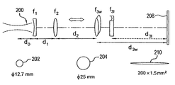
도 3은 광학시스템(렌즈 f31 및 f3w를 포함하는 플라잉 광학헤드(106) 내의 빔 쉐이핑 광학장치(110), 및 렌즈 f1 및 f2를 포함하는 빔확대기(104))의 예를 나타낸다. 한 측면에서, 도 3의 광학시스템은 도 5 및 도 6에서 도시된 길이와 폭을 갖는 연장된 빔을 생성할 수 있다. 도 3에서, f1 및 f2는 빔확대기(104)에 상응하는, 빔확대기 렌즈이며, 빔확대기(104)는 레이저로부터 레이저빔을 수렴하며; 레이저 f31 및 f3w는 빔 쉐이핑 원통형 렌즈, 플라잉 광학헤드(106)내의 빔 쉐이핑 광학장치(110)에 상응하도록 형성되고, 도 5 및 도 6에서 도시된 바와 같이 생성된 빔의 길이(l) 및 폭(w)을 결정한다. d0는 빔확대기의 렌즈 f1에 레이저로부터 나오는 빔웨이스트의 중심으로부터의 거리이고; d1은 렌즈 f1 및 f2 사이의 조절거리이고; d2는 비거리(108)에 상응하는 비거리이며; d31 d3w는 렌즈 f31 및 f3w 에서 유리(208)까지의 유효거리이다. 렌즈 f1 및 f2의 상대적 거리는 빔확대기(104)와 플라잉 광학헤드(106)사이의 비거리 d2를 따라서 빔 웨이스트의 중심 위치를 제어하기 위해 조절될 수 있다. 도 4는 광학시스템의 다른 실시예를 나타내며, 여기서 렌즈 f3w 및 f31의 상대적 위치는 다양하게 생성되는 빔 폭에 따라 결과적으로 변한다. 도 5 및 도 6에 도시된 바와 같이, 결과의 연장된 레이저빔의 길이(l)는 렌즈 f31에 의해 실질적으로 결정되고, 폭(w)은 렌즈 f3w에 의해 실질적으로 결정된다. 도 3 및 도 4는 물리광학적 빔 전달을 연구하기 위한 빔 경로를 나타낸 광학 개략도임을 주목해야 한다. 이러한 개략도는 유리(208)에 대한 비거리의 실제적인 방위(orientation)를 보여주는 것은 아니다.Figure 3 shows an example of an optical system (
이하에 나타낸, 표 1에는, 목표로 하는 빔 사이즈를 위한 광학 디자인 매개변수의 예가 제공된다. 표 1에서, f31 및 f3w에 대한 세로행은 이러한 렌즈들의 초점거리를 제공한다. 또한, d31 및 d3w에 대한 세로행은 렌즈 f31 과 f3w 사이의 거리 및 유리의 최초위치 또는 공칭목표를 나타낸다. 빔 사이즈 및 길이와 폭의 비율의 특정 값을 선택하는 것은 공정의 필요조건에 의해 정해지며, 그 조건에는 스코어링 스피드, 절단모서리(cut edge)의 직진도, 유리 굽힘의 각폭, 유리두께의 변화, 또는, 예를 들어, 성형공정 중의 유리의 임의적 이동에 의한 유리의 공칭목표위치로부터 플라잉 광학헤드의 빔 쉐이핑 광학장치에 대한 유리의 이동, 비거리(또는 유리 사이즈), 수용가능한 잔여 응력 수준, 가능한 레이저파워, 레이저모드의 특성 및 방식이 포함되지만, 이에 한정되는 것은 아니다. In Table 1 below, examples of optical design parameters for a target beam size are provided. In Table 1, the vertical rows for f 31 and f 3w provide the focal lengths of these lenses. The vertical rows for d 31 and d 3w also represent the distance between the lenses f 31 and f 3w and the initial position or nominal target of the glass. The selection of a beam size and a specific value of the ratio of the length to the width is determined by the process requirements and includes conditions such as the scoring speed, the straightness of the cut edge, the width of the glass bend, Alternatively, for example, the movement of the glass to the beam shaping optics of the flying optical head from the nominal target position of the glass by random movement of the glass during the molding process, the distance (or glass size), the acceptable residual stress level, But are not limited to, power and laser mode characteristics and schemes.
실시예Example
본 발명의 원리를 추가하여 설명하기 위해, 다음의 상세한 설명은 여기에 주장된 시스템 및 방법이 어떻게 만들어지고 평가될 수 있는지의 완전한 개시 및 설명을 갖는 종래의 일반적인 기술을 제공하기 위하여 시작된다. 본 상세한 설명은 순전히 발명의 실시예를 나타내기 위한 것이고, 발명자의 발명의 범위를 제한하기 위한 것이 아니다. 수치(예를 들어, 양, 온도, 기타)에 대한 정확성을 보증하기 위해 노력하였지만, 그럼에도 불구하고 약간의 오류 및 편차가 발생될 수 있다.To further illustrate the principles of the present invention, the following detailed description is given to provide a general description of the prior art, with a complete disclosure and description of how the claimed system and method may be made and evaluated. This detailed description is intended purely to illustrate embodiments of the invention and is not intended to limit the scope of the inventor's invention. Although efforts have been made to ensure accuracy with respect to numbers (eg, quantity, temperature, etc.), some errors and deviations may nevertheless occur.
상기에서 살펴보았듯이, 빔전달시스템의 고정부는, 하나의 실시예에서 레이저 및 빔확대기, 전체 비거리에 걸쳐 대체로 일정한 레이저빔의 특성을 유지 시킨다. 한 측면에서, 광학시스템은 TEM00 모드, 및 또한 D-모드라고 알려진 표준 가우스 레이저에 의해서 만들어질 수 있다. D-모드는 TEM01*(또는 "도넛(donut)"모드 및 TEM00모드(또는 "S-모드")의 60/40의 혼합이다. M2 인자는 빔 품질(quality)을 나타내기 위해 사용될 수 있고, 그리고 빔 사이즈는 1/e2 정의(definition)를 이용하여 결정될 수 있으며, 그 정의는 빔 세기가 ISO11146 기준에 따른 빔 세기의 최고값의 1/e2 으로 떨어졌을 때 위치로서 레이저빔의 경계(boundaries)가 정의된다. 완벽한 D모드는 인자 M2=1.67의 빔 품질을 가지며, 그러나 실질적인 M2 은 다양한 에너지 레벨에서 다양한 레이저에 대한 2.3 과 2.4 사이 어느 값을 갖는다. 그러므로, 1.7 내지 2.50의 평균 M2 값은 시스템 디자인을 위해 사용될 수 있다. 일반적으로, 실제 레이저빔은 1/M의 인자에 의해 변경된 웨이스트 사이즈를 갖는 가우스빔에 의해 모사될 수 있다. 하나의 예로, 레이저의 출력커플러(output coupler)로부터 0.2m 지점에서의 웨이스트를 갖는, 모델링을 목적으로 한 전형적인 빔 웨이스트 직경은 약 12.7mmm이다. As discussed above, the fixture of the beam delivery system maintains the characteristics of the laser beam in one embodiment, the laser and the beam expander, a substantially constant beam over the entire distance. In one aspect, the optical system can be made by a TEM00 mode, and also by a standard Gaussian laser known as D-mode. The D-mode is a mixture of TEMO * (or "donut" mode and TEM00 mode (or "S-mode") 60/40. M 2 factor can be used to indicate beam quality , And the beam size can be determined using a 1 / e 2 definition, the definition of which is that the beam intensity is 1 / e 2 of the highest value of the beam intensity according to ISO 11146 The boundaries of the laser beam are defined as positions when they fall. The perfect D mode has a beam quality of factor M 2 = 1.67, but the actual M 2 has a value between 2.3 and 2.4 for various lasers at various energy levels. Therefore, an average M 2 value of 1.7 to 2.50 can be used for system design. In general, the actual laser beam can be simulated by a Gaussian beam having a wasted size modified by a factor of 1 / M. As an example, a typical beam waist diameter for modeling purposes with a waist at a point of 0.2 m from the output coupler of the laser is about 12.7 mmm.
빔확대기는 레이저 빔사이즈를 증가시키고 원하는 위치의 웨이스트 중심에 빔을 지향시킨다. 확대비율은 레이저 매개변수 및 원하는 비거리를 고려하여 결정된다. 광학시스템에 의해 유도된 소정 빔확대기의 편향은 빔 품질을 떨어뜨리고 빔을 더욱 발산하게 할 수 있기 때문에 빔확대기의 편향을 최소한으로 유지시키는 것이 바람직하다. 시뮬레이션은, 다른 렌즈가 발명의 범위 내에 있다고 하더라도, 무시할 정도의 편차를 가진 높은 F-넘버의 구형 ZnSe 렌즈가 형성된 빔확대기를 보여준다. 최소한의 비점수차(非點收差)를 갖는 오프축(off-axis) 구형 거울을 기초로 한 빔확대기는 또한 상업적으로 가능하다. 그러므로 굴절 및 반사 빔확대기 모두가 선택될 수 있고, 무시할 수 있는 정도의 편차를 가질 것이다. 빔확대기는 빔확대정도를 고정시키기 위해 제공되거나, 빔확대정도의 조절을 위해 제공될 수 있다. The beam expander increases the laser beam size and directs the beam to the center of the waste at the desired location. The magnification ratio is determined by considering the laser parameters and the desired distance. It is desirable to keep the deflection of the beam expander to a minimum since the deflection of a given beam expander induced by the optical system can degrade the beam quality and cause the beam to further diverge. The simulation shows a beam expander in which a spherical ZnSe lens of high F-number with negligible variation is formed, even though other lenses are within the scope of the invention. A beam expander based on an off-axis spherical mirror with minimal astigmatism is also commercially viable. Therefore, both the refracted and reflected beam expander may be selected and will have a negligible deviation. The beam expander may be provided for fixing the degree of beam magnification, or may be provided for adjusting the degree of beam magnification.
많은 예에서, CO2 레이저빔과 같은, 레이저의 전달은 가우스빔의 전파와 유사하다. 만약 빔 웨이스트 사이즈가 wR0 및 품질 인자가 M2 라면 빔사이즈 wR(z)는 다음의 관계가 성립한다. In many instances, the transmission of a laser, such as a CO 2 laser beam, is similar to the propagation of a Gaussian beam. If the beam waist size is w R0 and the quality factor is M 2 The following relationship holds for the beam size w R (z).


여기서, 2z0는 레일리 거리이며, 여기서 z0는 z축의 원점이고 빔 웨이스트에 일치하도록 정의되며, z는 빔 웨이스트로부터 빔축을 지나는 거리 및 λ는 파장을 나타낸다. 종래의 일반적인 기술로 알려져 있듯이, 다채널 광학시스템을 통한 레이저빔의 전달은 ABCD 행렬을 이용하여 실험할 수 있다. 실험된 결과는, ZEMAX의 물리적 광전파 실험과 비교하여 볼 때, 뛰어난 결과를 보여준다. 도 7은 만약 빔확대기에서 나오는 빔의 빔 웨이스트가 약 14mm라면, 빔 폭의 변화는 대략 6m의 비거리에 걸쳐서 아마도 약 6% 내지 13%인 것을 나타낸다. 도 8은 만약 빔 웨이스트가 빔확대기에 의해 약 20mm 까지 증가하게 된다면, 빔 폭의 변화는 대략 6m의 비거리에서 조차 약 3%보다 작도록 감소하게 된다. 빔확대기에서 나오는 빔의 직경이 증가하면 할수록, 더 긴 비거리에 걸쳐 빔 직경의 변화가 감소한다. 한 측면에서, a2×빔 비율이 선택될 수 있으며, 다른 비율의 빔확대기들이 사용될 수 있다고 하더라도, 그 선택된 빔 비율은 비거리의 레이저빔 사이즈의 2배가 된다.Where 2 z 0 is the Rayleigh distance, where z 0 is the origin of the z-axis and is defined to coincide with the beam waist, z the distance from the beam waist through the beam axis, and λ the wavelength. As is known in the prior art, the transmission of a laser beam through a multi-channel optical system can be tested using an ABCD matrix. The experimental results show excellent results when compared with the ZEMAX physical light propagation experiments. Figure 7 shows that if the beam waist of the beam emerging from the beam expander is about 14 mm, the variation in beam width is probably about 6% to 13% over a distance of about 6 m. 8 shows that if the beam waist is increased to about 20 mm by the beam expander, the beam width variation is reduced to less than about 3% even at a distance of about 6 m. The greater the diameter of the beam emerging from the beam expander, the smaller the beam diameter variation over a longer distance. In one aspect, the a2 x beam ratio can be selected, and even if different proportions of beam expanders can be used, the selected beam ratio is twice the distance of the laser beam size.
빔확대기에 추가하여, 빔 전파시스템의 일 실시예는 몇몇의 라우팅 미러(routing mirror) 및/또는 확장된 빔을 플라잉 광학헤드로 지향시키도록 하기 위한 빔스위치를 포함할 수 있다. 빔튜브(beam tube)는 광경로를 고정하기 위해 사용될 수 있고, 광경로는 플렉시블 벨로우(flexible bellow)내에 포함될 수 있다. 일반적으로, 만약 빔튜브가 사용된다면, 빔튜브의 내측 직경은 적어도 확장된 빔의 두배는 되어야 한다. 빔튜브의 사용은 또한 반사미러(빔 벤더(beam bender))의 미러 사이즈의 선택에 영향을 미친다. In addition to the beam expander, one embodiment of the beam propagation system may include some routing mirrors and / or a beam switch to direct the expanded beam to the flying optical head. A beam tube may be used to secure the optical path, and the optical path may be included within a flexible bellow. In general, if a beam tube is used, the inner diameter of the beam tube should be at least twice as large as the expanded beam. The use of a beam tube also affects the choice of the mirror size of the reflective mirror (beam bender).
빔 쉐이핑 광학장치, 원통형 렌즈를 이용한 일실시예에서, f3w 및 f31은 예를 들어, 도 3 및 도 4에 도시된 바와 같이 직경 약 25mm의 사이즈의 원형빔으로부터 대략 60 ~ 200mm 길이 및 약 1 ~ 1.5mm 폭의 타원형빔으로 변형시킨다. 다른 실시예에서는, 원형빔은 대략 60mm 내지 30mm의 빔 길이 및 대략 1.0mm 내지 3.0mm의 빔 폭을 갖는 확장된 빔으로 변형될 수 있다. In one embodiment using a beam shaping optics, a cylindrical lens, f 3w and f 31 may be approximately 60 to 200 mm long and about 50 to 200 mm long, for example, from a circular beam having a diameter of about 25 mm as shown in Figures 3 and 4, And deformed into an elliptical beam having a width of 1 to 1.5 mm. In another embodiment, the circular beam can be deformed into an expanded beam having a beam length of approximately 60 mm to 30 mm and a beam width of approximately 1.0 mm to 3.0 mm.
도 3에서, 예를 들면, 대략 13mm 직경의 빔 웨이스트(202)를 갖는 레이저빔(200)이 빔확대기로 입사되며, 본 실시예에서 렌즈 f1 및 f2를 포함하며, 여기서 레이저빔(200)은 대략 25mm 의 직경의 빔 웨이스트(204)를 갖는 레이저빔으로 확대된다. 확대된 빔의 직경은 확대된빔의 빔웨이스트(204)가 비거리 d2의 중심 근처에 형성될 때 광학헤드의 비거리 d2 전체에 걸쳐 대체로 일정하게 유지된다. 확대된 레이저빔은 그 다음 플라잉 광학헤드로 입사되며, 여기서 빔 쉐이핑 광학장치는 유리(208)에 형성된 확대된 빔(206)을 형성하는 본 실시예의 렌즈 f31 및 f3w를 포함한다. 본 실시예에서, f31은 유리(208)에 형성되는 확대된 빔(206)의 길이를 확대하는데 사용되고, f3w는 유리(208)에 형성되는 확대된 빔(206)의 폭을 확장하는데 사용된다. 도 3에 나타난 실시예에서와 같이, 렌즈 f31 부터 유리(208)의 표면까지의 공칭거리(nominal distance) d31은 렌즈 f3w 부터 유리(208)의 표면까지의 공칭거리 d3w보다 크다. 도 3에 도시된 바와 같이, 본 실시예에서의 빔쉐이핑광학장치의 배열은 결과적으로 유리(208) 표면에 대략 200×1.0mm2 확대된 빔(206)을 만든다. 유사하게, 도 4에 도시된 바와 같이, 본 실시예에서의 빔 쉐이핑 광학장치의 배열은 결과적으로 유리(208) 표면에 대략 200×1.5mm2 확대된 빔(210)을 만든다. 도 4의 도시된 실시예에서와 같이, 렌즈 f31 부터 유리(208)의 표면까지의 공칭거리 d31은 렌즈 f3w 부터 유리(208)의 표면까지의 공칭거리 d3w보다 작다. 도 3 및 도 4에 도시된 것과 같은 빔 쉐이핑 광학장치는 사실상의 하나의 예이고 다른 디자인들이 다양한 빔사이즈, 렌즈배열, 비거리, 및 유리에 형성되는 빔형상을 결과적으로 형성할 수 있는 것으로 이해되어야 한다. In Figure 3, for example, a
플라잉 광학헤드에 입사하는 고도로 조준된 레이저빔의 경우, 주요변수는 국지적인 유리표면과 렌저 f31 및 f3w 사이에서의 거리 d31 및 d3w의 변화에 기인하며, 각각, 예를 들어, 유리 굽힘, 유리 두께의 변화 또는, 예를 들어, 유리성형중에 유리의 임의적인 이동과 같은 유리의 공칭목표위치(nominal target position)로부터의 광학장치에 대한 유리의 이동에 기인한다. d31 및 d3w의 변화는 유리표면의 실질적인 빔의 길이 및 폭에 영향을 준다. 그 영향은 가우스빔 전파에 기초하여 평가될 수 있다. In the case of a highly collimated laser beam incident on the flying optical head, the main variable is due to the variation of the distances d 31 and d 3w between the local glass surface and the lenses f 31 and f 3w , Bending, changes in glass thickness, or movement of the glass relative to the optical device from a nominal target position of the glass, such as, for example, random movement of glass during glass forming. The change in d 31 and d 3w affects the length and width of the substantial beam of the glass surface. The influence can be evaluated based on the Gaussian beam propagation.
일실시예에서, 확장된 빔은 오목 원통형 렌즈 및 거울을 사용하여 조준되어 발사됨으로써 발생된다. 발산각 θ는, 도 5에 도시된 바와 같이, 렌즈 f31 에 대한 유리(208) 위치의 변화 Δ의 결과로서 빔 길이의 변화의 정도를 결정하며, 예를 들어, 유리 굽힘, 유리 두께의 변화 또는, 예를 들어, 유리성형중에 유리의 임의적인 이동과 같은 유리의 공칭목표위치로부터의 광학장치에 대한 유리의 이동과 같은 것에 기인한다. 도 5의 도시된 내용을 이용하는 실시예로써, 200mm 빔 길이를 발생시키기 위해,(l), ±25mm의 유리위치의 변화 Δ에 대해 ±2.5% 보다 작은 변화를 가지며, 산개(fan-out)각도가 6°보다 작아야 하고, 렌즈와 유리 사이의 떨어진 거리가 적어도 1미터이어야 하는 삼각법에 의해 도시될 수 있다. 빔 길이의 변화는 빔을 조준(collimating)함으로써 경감 또는 제거할 수 있다. 빔 길이를 더 줄이기 위해서는, 변화는 비례하여 경감해야 한다.In one embodiment, the expanded beam is generated by aiming and firing using a concave cylindrical lens and a mirror. The divergence angle θ determines the degree of change in beam length as a result of a change Δ in the position of the
일실시예에서, 제2 원통형 렌즈 f3w는 약 1 내지 3mm의 폭으로 빔의 다른 축으로 초점을 맞춘다. 도 6은 렌즈 f3w에 대하여 유리(208)의 위치의 변화 Δ가 어떻게 빔의 폭을 변화시키는지 나타내고 있다. 광경로와 같이, 유리 위치의 변화 Δ에 덜 민감한 빔의 폭을 만들기 위해서, 유리는 레일리 범위 중심에 가깝게 위치하는 것이 바람직하다. 레일리 범위는, 빔 웨이스트의 영향을 받고, 렌즈 f3w 에 대한 유리(208)의 위치의 최대 변화 Δ 보다 훨씬 크다.In one embodiment, the second cylindrical lens f 3w focuses on a different axis of the beam with a width of about 1 to 3 mm. Fig. 6 shows how the change? In the position of the
도 9 및 도 10은, 한 예로써, 1mm 및 1.5mm의 빔 폭의 예에 대한 빔 웨이스트의 중심으로부터 유리표면의 편향의 함수로써 빔 폭 변화를 나타낸다. 도 9 및 도 10에서 알 수 있듯이 빔 폭의 변화는 빔 폭이 1mm 에서 1.5mm 까지 증가됨에 따라 감소한다. 레이저빔의 품질인자 M2 또한 두 경우 모두에 차이가 발생한다. 더 작은 빔폭의 변화의 결과 더 좋은 빔의 품질이 형성되고, 여기서, 유리형상에 대한 민감도가 더 낮은 시스템을 달성할 수 있다. 특히, 도 9는 1mm의 목표 빔 값을 나타내며, 빔 웨이스트의 중심으로부터 유리위치의 편향은 30% 폭 변화에 걸쳐 발생할 수 있으며, 반면에 도 10은 1.5mm의 목표 빔 폭을 나타내며, 변화는 7%로 감소 되었다. 레이저빔의 품질인자 M2 또한 두 경우 모두에 차이가 발생한다.Figures 9 and 10 illustrate, as an example, a beam width variation as a function of the deflection of the glass surface from the center of the beam waist for examples of beam widths of 1 mm and 1.5 mm. As can be seen from Figs. 9 and 10, the variation of the beam width decreases as the beam width increases from 1 mm to 1.5 mm. The quality factor M 2 of the laser beam also varies in both cases. A change in the smaller beam width results in a better beam quality, where a system with lower sensitivity to the glass shape can be achieved. In particular, FIG. 9 shows a target beam value of 1 mm, and the deviation of the glass position from the center of the beam waist may occur over a 30% width change, whereas FIG. 10 represents a target beam width of 1.5 mm, %. The quality factor of the laser beam M 2 There is also a difference in both cases.
하나의 예로, 도 3 및 도 4에 도시된 것과 같은 광학시스템은 근축 가오스빔 전파에 의해 실험되고 평가된다. 시스템 평가에 대한 장점함수(merit function)는 목표로 하는 빔 사이즈에 근접함, 비거리 및 빔 쉐이핑 광학장치 f31 및 f3w 에서부터 유리 표면까지의 거리 d31 및 d3w의 변화에 걸쳐 최소의 빔 영역 변화, 예를 들면, 유리 굽힘, 또는 유리 두께의 변화, 또는 예를 들면, 성형공정 중의 유리의 임의적 이동과 같은 유리의 공칭목표위치로부터 광학장치에 대한 유리의 이동에 기초가 된다. 목표 빔 사이즈는 빔 쉐이핑 렌즈 f3w 및 f31의 초점길이를 결정하며, 반면에 d31 및 d3w는, 최상의 빔 사이즈 일관성을 위해 선택된다. 목표 빔사이즈의 결과는 상기한 표 1과 같이 요약될 수 있으며, 빔 폭이 단지 f3w에 의해 결정되고, 그리고 f31에 의해 빔의 길이가 결정되기 때문에, 표 1은 나타낸 바와 같이 적어도 4가지 빔 사이즈 결합의 디자인을 포함한다.As an example, the optical system as shown in Figures 3 and 4 is tested and evaluated by paraxial GaAs beam propagation. The advantage function for system evaluation (merit function) is also close to the beam size of the target, distance and beam shaping optics f 31 and f 3w from the distance d 31, and the minimum beam area over the change in d 3w to the glass surface Change of the glass to the optical device from the nominal target position of the glass such as, for example, glass bending, or a change in the glass thickness, or for example, an arbitrary movement of the glass during the molding process. The target beam size determines the focal lengths of the beam shaping lenses f 3w and f 31 , while d 31 and d 3w are selected for best beam size consistency. Because the result of the target beam size is can be summarized in the above Table 1, a beam is only determined by the f 3w width, and the length of the beam determined by f 31, table 1 is at least four as shown Beam size coupling design.
도 11 내지 도 14는 렌즈 f3w와 유리 사이의 거리 d3w의 함수, 렌즈 f31과 유리 사이의 거리 d31의 함수, 여기서 거리 d3w 및 d31은 유리 굽힘(또는 유리 두께의 변화, 또는 유리의 공칭목표위치로부터 광학장치에 대한 유리의 이동, 예를 들면, 성형공정 중에 유리의 임의적 이동과 같은 것에 기인한다), 예를 들면, 그리고 비거리 d2의 함수로써 유리표면의 빔 사이즈(폭 및 길이)를 나타내고 있다. 도시된 바와 같이, 유리 위치의 변화는 1.5mm 보다 작은 폭에서 빔 사이즈의 변화에 가장 큰 기여자이다. 11 to 14 are the lens f 3w as a function of the distance d 31 between the functions, the lens f 31 and the glass of the distance d 3w between the glass, in which the distance d 3w and d 31 is a glass-bending (or a change in glass thickness, or For example, due to the movement of the glass from the nominal target position of the glass to the optical device, for example the random movement of the glass during the molding process), for example, and as a function of the distance d 2 , And length). As shown, the change in glass position is the largest contributor to beam size variation at widths less than 1.5 mm.
약 1.4mm의 빔 폭에 대해서 도 11 및 도 12에 도시된 결과는, 도 4에 도시된 것과 같은 광학시스템에 대한 것이고, 최초에 대략 1200mm로 설정된 d3w 및 최초에 대략 1000mm로 설정된 d31을 갖고, +/-20mm의 거리(d31 또는 d3w중 어느 하나)의 변화에 대해 빔 사이즈 폭 변화는 +/- 5% 이내이고 빔 사이즈 길이 변화는 +/-2%보다 작다.The results shown in Figures 11 and 12 for a beam width of about 1.4 mm are for the optical system as shown in Figure 4 and have d3w originally set at about 1200 mm and d31 initially set at about 1000 mm, For changes in the distance of +/- 20 mm (either d 31 or d 3w ), the beam size width variation is within +/- 5% and the beam size length variation is less than +/- 2%.
약 0.95mm 내지 약 1.0mm의 폭의 폭이 좁은 빔에 대해서도, 도 13 및 도 14는 도 3에 도시된 것과 같은 광학시스템을 나타내며, 최초에 대략 800mm로 설정된 d3w 및 최초에 대략 1000mmm로 설정된 d31을 갖고, ±10mm 이내의 거리(d3w 또는 d31중 어느 하나)의 변화에 대해 빔 사이즈 폭 변화는 +/-5%를 초과하지 않고 빔 사이즈 길이 변화는 +/- 2%를 초과하지 않는다.13 and 14 show an optical system such as that shown in Fig. 3 for a narrow beam of width from about 0.95 mm to about 1.0 mm, with d 3w initially set at about 800 mm and initially set at about 1000 mm d 31 and the beam size width variation does not exceed +/- 5% and the beam size length variation exceeds +/- 2% for a variation of the distance (either d 3w or d 31 ) within +/- 10 mm I never do that.
이하의 표 2와 같이, 바람직한 실시예의 빔 폭 및 길이의 목표 값과 일치하기 위해 실제렌즈의 상세한 설명을 요약하였다. 표 2는 본 실시예에 대한 실제 평볼록(plano-convex(PO/CX))/평오목(plano-concave(PO/CC)) 원통형 렌즈 처방(prescriptions)(렌즈물질 ZnSe; 10.6㎛로 반사방지 코팅된)을 제공한다. 이러한 렌즈 처방들은 또한 다른 렌즈물질에 사용될 수 있고, 그리고 반사방지 코팅이 있거나 또는 없는 경우에도 사용될 수 있다. 평볼록 및 평오목렌즈 디자인의 곡률 반경들은 가장 효과적인 초점길이에 근거해서 계산된다. 이런 특별한 광학시스템 대해 음화원통형 렌즈(negative cylindrical lens) f31의 첫 설치 위치는 목표 유리위치로부터 10mm의 거리 d31에 맞춘다. 렌즈 f3w에 대한 첫 설치위치는 초점길이의 함수이고, 그리고 거리 d3w가 렌즈 f3w의 초점거리와 대략 동일하도록 하기 위해 설치되며, 이것은 빔 폭에 플라잉 위치(flying position)의 영향을 최소화하는 것을 돕는다.
The detailed description of the actual lens is summarized to match the target values of the beam width and length of the preferred embodiment, as shown in Table 2 below. Table 2 shows the relationship between the actual planar convex (PO / CX) / plano-concave (PO / CC) cylindrical lens prescriptions (lens material ZnSe; Coated). These lens prescriptions can also be used for other lens materials, and can also be used with or without antireflective coatings. The curvature radii of the plano-convex and flat-concave lens designs are calculated based on the most effective focal length. For this particular optical system, the first installation position of the negative cylindrical lens f 31 is adjusted to a distance d 31 of 10 mm from the target glass position. The first installation position for the lens f 3w is a function of the focal length and is provided so that the distance d 3w is approximately equal to the focal length of the lens f 3w which minimizes the effect of the flying position on the beam width Help.
(mm)Effective Focal Length
(mm)
실시예의 적용Application of the embodiment
레이저 스코어링 시스템의 실시예는, 예를 들어, 도 15의 개략적으로 도시된 단면도와 같이 다운드로우(down-draw) 유리제조공정 또는 다운드로우 융합(fusion) 유리제조공정과 같은 유리제조공정에 결합될 수 있다. 도 15는 수직방향의 유리를 이용할 수 있는 것으로서 레이저 스코어링 시스템의 실시예를 도시하고 있다. 물론, 여기에 개시된 레이저 스코어링 시스템은 또한 수평방향, 또는 다른방향으로 향한 유리에 대해서도 이용될 수 있다. 도 15에 도시된 바와 같이, 용융된 유리(702)가 아이소파이프(isopipe; 704)로 넘쳐 흐르며, 종래의 일반적인 기술로 알려져 있듯이, 그리고 아이소파이프(704) 아래에서 융합된다. 그 다음 고온의 유리가 형성되고 둘 또는 그 이상의 롤러(710)의 도움으로 아래쪽으로 이동하고, 계속해서 도 15가 도시된 페이지(page)에 대해 아래 방향(즉, 도 15에서 도시된 좌표시스템에 따른 "y방향")으로 움직인다. 도 15에서와 같이 도시된 레이저 스코어링 시스템은 공정을 거치는 유리를 스코어링 하기 위한 스코어링 장치(712)를 포함한다. 한 측면에서, 스코어링 장치(712)는, 실질적으로 상기에서 살펴본 바와 같이, 레이저, 빔확대기 및 플라잉 광학헤드를 포함할 수 있다. 빔확대기는 레이저로부터 레이저빔을 수용하고 대략 레이저 및 빔확대기에 대해 이동하는 플라잉 광학헤드에 의해 횡단한 비거리의 중심에 빔 웨이스트를 갖는 확대된 레이저빔으로 레이저빔을 확대시킨다. 도 15에 도시된 바와 같이, 플라잉 광학헤드는 +/- x축 방향(즉, 도 15의 평면 속으로 또는 바깥으로)으로 이동할 수 있다. 고온의 유리에서 유리 위치의 변화 Δ 는(유리 굽힘, 유리 두께의 변화, 또는 예를 들면, 성형공정 중의 유리의 임의적 이동과 같은 유리의 공칭목표위치로부터 플라잉 광학헤드의 광학장치에 대한 유리의 이동과 같은 것에 의한 변화) +/- z방향이며, 반면에 유리는 일반적으로 제조공정 중에 y방향으로 이동한다. 플라잉 광학헤드는 빔확대기로부터 확대된 레이저빔을 수용하도록 형성되고, 확대된 레이저빔을 연장된 레이저빔(714)으로 초점을 맞춘다. 한 측면에서 연장된 레이저빔(714)은 빔 웨이스트와 빔 웨이스트의 중심에 대해 +/-5mm보다 큰 확장된 초점심도를 갖는다. 연장된 레이저빔(714)은 적어도 유리의 일부가 확장된 초점심도 이내에 위치하기 위하여 배치된 유리를 스코어링 하기 위해 확장된 초점심도 전체에 걸쳐 충분한 에너지밀도를 갖는다. 도 15에서는 스코어링 이후에 유리의 열적 충격을 위한 장치가 도시되지 않았다. 일단 유리가 스코어되면, 분리 및/또는 제조공정으로부터 이송될 수 있다. 예를 들면, 유리 취급 시스템 또는 로봇은 유리의 분리 완성 및 제조영역으로부터의 이송에 사용될 수 있다. An embodiment of the laser scoring system may be coupled to a glass manufacturing process, such as a down-draw glass manufacturing process or a down-draw fusion glass manufacturing process, for example, as shown in the schematic cross- . Fig. 15 shows an embodiment of a laser scoring system as being able to use vertical glass. Of course, the laser scoring system disclosed herein can also be used for horizontal or other orientated glasses. 15,
결론적으로, 여기의 상세한 설명은 레이저 스코어링 시스템에 관한 것이며, 능동적인 보상없이, 그 시스템은 거의 일정한 사이즈의 레이저빔의 물질과, 상응하는, 거의 일정한 에너지밀도로 지향되는 것을 허용하며, 비거리를 따라 광학헤드 위치의 변화 및 광학헤드와 유리의 거리에 둔감하다. 플라잉 위치의 변화에 의해 유도되는 빔 사이즈의 변화는 4m까지의 비거리에 걸쳐 1%보다 작도록 최소화 될 수 있다. 동시에, 유리표면과 광학헤드 사이의 거리의 변화에 기인한 빔 사이즈의 변화는 +/-5mm 보다 큰 거리의 변화에 걸쳐서 까지 레이저 스코어링 공정을 거의 일정하게 유지하기 위하여 최소화 될 수 있다.Consequently, the detailed description herein relates to a laser scoring system, which, without active compensation, allows the system to be oriented at a substantially constant energy density with a material of a substantially constant size laser beam, It is insensitive to changes in the position of the optical head and the distance between the optical head and the glass. The change in the beam size induced by the change of the flying position can be minimized to less than 1% over the distance up to 4 m. At the same time, changes in beam size due to variations in the distance between the glass surface and the optical head can be minimized to keep the laser scoring process almost constant over a distance greater than +/- 5 mm.
시스템이 바람직한 실시예 및 특정예와 연결되어 설명하고 있다고 할지라도, 그것은 설명된 특정 실시예로 제한되는 범위로 의도된 것은 아니며, 여기서 설명된 실시예는 발명을 제한하기 보다는 모든 측면에서의 실례가 되는 것을 의도한 것이다. Although the system is described in connection with the preferred and specific examples, it is not intended to be limited to the specific embodiments described, and the embodiments described herein are intended to be illustrative, It is intended to be.
당해 기술분야의 통상의 지식을 가진자가 본 발명의 범위 및 기술적 사상의 벗어남 없이 다양한 수정 및 변형이 가능함은 명백하다. 다른 실시예들은 명세서 및 여기에 개시된 원리의 실시의 고찰로부터 당업자에게는 자명하다. 명세서 및 실시예들은 오로지 예시로써 고려된 것이며, 진정한 발명의 범위 및 기술적 사상은 다음의 청구항을 통해 나타나도록 의도되었다.It will be apparent to those skilled in the art that various modifications and variations can be made in the present invention without departing from the scope and spirit of the present invention. Other embodiments will be apparent to those skilled in the art from consideration of the specification and practice of the principles disclosed herein. It is intended that the specification and examples be considered as exemplary only, with a true scope and spirit of the invention being indicated by the following claims.
102: 레이저 104: 빔확대기
106: 광학헤드 112: 반사미러
202, 204: 빔 웨이스트 702: 용융된 유리
704: 아이소파이프 710: 롤러
712: 스코어링 장치102: laser 104: beam expander
106: optical head 112: reflection mirror
202, 204: beam waist 702: molten glass
704: Isopipe 710: Roller
712: Scoring device
Claims (20)
상기 광학헤드에 결합되어 상기 광학헤드로 출력을 제공하는 레이저를 포함하며,
상기 빔 웨이스트는 중심(center)을 갖고, 상기 연장된 레이저빔은 빔 웨이스트의 중심에 대해 +/-5mm 보다 큰 확장된 초점심도를 갖고, 상기 연장된 레이저빔은 확장된 초점심도 내에 배치된 물질의 일부를 스코어링 하기에 충분한 확장된 초점심도 전체에 걸쳐 에너지 밀도를 갖는 시스템.An optical head having a beam shaping optics for receiving an output from the laser and focusing the output to an extended laser beam having a beam waist, and
And a laser coupled to the optical head to provide an output to the optical head,
Wherein the beam waist has a center and the extended laser beam has an expanded focal depth greater than +/- 5 mm with respect to the center of the beam waist and the extended laser beam is focused on a material Wherein the system has an energy density throughout the extended focal depth sufficient to score a portion of the image.
제조된 유리를 스코어링하기 위해 배치된 스코어링 장치를 포함하며,
상기 스코어링 장치는:
레이저;
상기 레이저로부터 레이저빔을 수용하도록 배치되고, 상기 레이저빔을 중심을 갖는 웨이스트를 구비한 확대된 레이저빔으로 확대시키는 빔확대기; 및
상기 확대된 레이저빔을 수용하도록 배치되고, 빔확대기에 대해 중심을 갖는 비거리에 걸쳐 이동될 수 있는 플라잉 광학헤드를 포함하고,
상기 빔확대기는 확대된 레이저빔의 웨이스트의 중심이 비거리의 중심에 있도록 확대된 레이저빔을 형성하며,
상기 플라잉 광학헤드는 확대된 레이저빔을 중심을 갖는 빔 웨이스트를 갖는 연장된 레이저빔으로 변경하도록 구성되며, 상기 연장된 레이저빔은 연장된 레이저빔의 웨이스트의 중심에 대해 +/-5mm보다 큰 확장된 초점심도를 가지며, 상기 연장된 레이저빔은 유리를 스코어링 하기에 충분한 확장된 초점심도 전체에 걸친 에너지밀도를 갖고,
상기 유리 제조장치 및 스코어링 장치는 유리 제조장치에 의해 제조된 유리의 일부분이 상기 확장된 초점심도 내에 배치되도록 상호 상대적으로 배치되는 시스템.A glass manufacturing apparatus for manufacturing glass; And
And a scoring device arranged to score the manufactured glass,
Wherein the scoring device comprises:
laser;
A beam expander arranged to receive a laser beam from the laser and to enlarge the laser beam into an enlarged laser beam having a centered waste; And
And a flying optical head disposed to receive the enlarged laser beam and movable over a distance having a center with respect to the beam expander,
The beam expander forms an enlarged laser beam so that the center of the waist of the enlarged laser beam is at the center of the distance,
Wherein the flying optical head is configured to change an enlarged laser beam to an extended laser beam having a beam waist centered, the extended laser beam having an expansion greater than +/- 5 mm relative to the center of the waist of the extended laser beam Wherein the extended laser beam has an energy density over an extended focal depth sufficient to score the glass,
Wherein the glass manufacturing apparatus and the scoring apparatus are disposed relative to one another so that a portion of the glass produced by the glass manufacturing apparatus is disposed within the extended focal depth.
레이저와 광학헤드 사이에 배치된 빔확대기를 더 포함하고, 상기 빔확대기는 레이저로부터의 출력을 수용하고, 상기 레이저로부터의 출력을 확대된 레이저빔으로 확대시키며, 상기 확대된 레이저빔을 광학헤드로 전달하고,
상기 빔확대기는 고정된 위치에 형성되고 상기 광학헤드는 빔확대기에 대해 이동하는 플라잉 광학헤드이고,
상기 플라잉 광학헤드는 0.5m 내지 6m의 비거리를 갖고, 상기 확대된 빔은 중심을 갖는 웨이스트를 갖고, 상기 빔확대기는 비거리의 중심에서 상기 확대된 레이저빔의 웨이스트의 중심을 투사하도록 구성되는 시스템.The method according to claim 1,
Further comprising a beam expander disposed between the laser and the optical head, the beam expander receiving an output from the laser, magnifying the output from the laser into an enlarged laser beam, For example,
Wherein the beam expander is formed at a fixed position and the optical head is a flying optical head moving with respect to the beam expander,
Wherein the flying optical head has a distance of 0.5 m to 6 m and the enlarged beam has a waist having a center and the beam expander is configured to project the center of the waist of the enlarged laser beam at the center of the distance.
상기 확장된 초점심도는 +/-20mm 이하이고, 상기 연장된 레이저빔은 소정의 빔 길이 및 빔 폭을 가지며, 상기 빔 폭은 확장된 초점심도의 범위에 걸쳐 +/-5% 미만으로 변화하고 상기 빔 길이는 확장된 초점심도의 범위에 걸쳐 +/-2% 미만으로 변화하는 시스템.The method according to claim 1,
Wherein the extended focal depth is +/- 20 mm or less, the extended laser beam has a predetermined beam length and beam width, the beam width varies less than +/- 5% over a range of extended focal depth Wherein the beam length varies less than +/- 2% over a range of extended depth of focus.
상기 연장된 레이저빔은 60mm 내지 300mm의 빔 길이 및 1mm 내지 3mm의 빔 폭을 더 포함하고, 상기 확장된 초점심도는 +/-10mm 이상이고,
상기 확장된 초점심도 전체에 걸친 에너지밀도는 5% 이하로 변화하는 시스템.The method according to claim 1,
Wherein the extended laser beam further comprises a beam length of 60 mm to 300 mm and a beam width of 1 mm to 3 mm, the extended depth of focus is at least +/- 10 mm,
Wherein the energy density across the extended focal depth varies by no more than 5%.
Applications Claiming Priority (5)
| Application Number | Priority Date | Filing Date | Title |
|---|---|---|---|
| US12894908P | 2008-05-27 | 2008-05-27 | |
| US61/128,949 | 2008-05-27 | ||
| US12/220,948 US8053704B2 (en) | 2008-05-27 | 2008-07-30 | Scoring of non-flat materials |
| US12/220,948 | 2008-07-30 | ||
| PCT/US2009/002988 WO2009151527A2 (en) | 2008-05-27 | 2009-05-14 | Scoring of non-flat materials |
Publications (2)
| Publication Number | Publication Date |
|---|---|
| KR20110021956A KR20110021956A (en) | 2011-03-04 |
| KR101428141B1 true KR101428141B1 (en) | 2014-08-08 |
Family
ID=41378489
Family Applications (1)
| Application Number | Title | Priority Date | Filing Date |
|---|---|---|---|
| KR1020107029167A KR101428141B1 (en) | 2008-05-27 | 2009-05-14 | Scoring of non-flat materials |
Country Status (6)
| Country | Link |
|---|---|
| US (1) | US8053704B2 (en) |
| JP (1) | JP5563562B2 (en) |
| KR (1) | KR101428141B1 (en) |
| CN (1) | CN102046545B (en) |
| TW (1) | TWI404683B (en) |
| WO (1) | WO2009151527A2 (en) |
Families Citing this family (50)
| Publication number | Priority date | Publication date | Assignee | Title |
|---|---|---|---|---|
| WO2010108061A2 (en) * | 2009-03-20 | 2010-09-23 | Corning Incorporated | Precision laser scoring |
| US8932510B2 (en) | 2009-08-28 | 2015-01-13 | Corning Incorporated | Methods for laser cutting glass substrates |
| WO2011056781A1 (en) * | 2009-11-03 | 2011-05-12 | Corning Incorporated | Laser scoring of a moving glass ribbon having a non-constant speed |
| US8946590B2 (en) | 2009-11-30 | 2015-02-03 | Corning Incorporated | Methods for laser scribing and separating glass substrates |
| US8720228B2 (en) * | 2010-08-31 | 2014-05-13 | Corning Incorporated | Methods of separating strengthened glass substrates |
| US8677783B2 (en) | 2011-11-28 | 2014-03-25 | Corning Incorporated | Method for low energy separation of a glass ribbon |
| US9938180B2 (en) * | 2012-06-05 | 2018-04-10 | Corning Incorporated | Methods of cutting glass using a laser |
| US9610653B2 (en) | 2012-09-21 | 2017-04-04 | Electro Scientific Industries, Inc. | Method and apparatus for separation of workpieces and articles produced thereby |
| WO2014079478A1 (en) | 2012-11-20 | 2014-05-30 | Light In Light Srl | High speed laser processing of transparent materials |
| US9212081B2 (en) * | 2012-11-21 | 2015-12-15 | Corning Incorporated | Methods of cutting a laminate strengthened glass substrate |
| TWI606018B (en) | 2012-11-29 | 2017-11-21 | 康寧公司 | Methods and apparatus for fabricating glass ribbon of varying widths |
| EP2754524B1 (en) | 2013-01-15 | 2015-11-25 | Corning Laser Technologies GmbH | Method of and apparatus for laser based processing of flat substrates being wafer or glass element using a laser beam line |
| EP2781296B1 (en) | 2013-03-21 | 2020-10-21 | Corning Laser Technologies GmbH | Device and method for cutting out contours from flat substrates using a laser |
| KR102246534B1 (en) | 2013-06-26 | 2021-04-30 | 코닝 인코포레이티드 | Glass ribbon breaking devices and methods of producing glass sheets |
| CA2924823C (en) * | 2013-09-24 | 2022-04-19 | Ipg Photonics Corporation | Laser processing systems capable of dithering |
| US9850160B2 (en) | 2013-12-17 | 2017-12-26 | Corning Incorporated | Laser cutting of display glass compositions |
| US9701563B2 (en) | 2013-12-17 | 2017-07-11 | Corning Incorporated | Laser cut composite glass article and method of cutting |
| US20150165560A1 (en) | 2013-12-17 | 2015-06-18 | Corning Incorporated | Laser processing of slots and holes |
| US9517963B2 (en) | 2013-12-17 | 2016-12-13 | Corning Incorporated | Method for rapid laser drilling of holes in glass and products made therefrom |
| US10442719B2 (en) | 2013-12-17 | 2019-10-15 | Corning Incorporated | Edge chamfering methods |
| US11556039B2 (en) | 2013-12-17 | 2023-01-17 | Corning Incorporated | Electrochromic coated glass articles and methods for laser processing the same |
| US9815730B2 (en) | 2013-12-17 | 2017-11-14 | Corning Incorporated | Processing 3D shaped transparent brittle substrate |
| US9676167B2 (en) | 2013-12-17 | 2017-06-13 | Corning Incorporated | Laser processing of sapphire substrate and related applications |
| CN106687419A (en) | 2014-07-08 | 2017-05-17 | 康宁股份有限公司 | Methods and apparatuses for laser processing materials |
| EP3169479B1 (en) | 2014-07-14 | 2019-10-02 | Corning Incorporated | Method of and system for arresting incident crack propagation in a transparent material |
| US11648623B2 (en) * | 2014-07-14 | 2023-05-16 | Corning Incorporated | Systems and methods for processing transparent materials using adjustable laser beam focal lines |
| JP6788571B2 (en) | 2014-07-14 | 2020-11-25 | コーニング インコーポレイテッド | Interface blocks, systems and methods for cutting transparent substrates within a wavelength range using such interface blocks. |
| EP3169635B1 (en) | 2014-07-14 | 2022-11-23 | Corning Incorporated | Method and system for forming perforations |
| WO2016028580A1 (en) * | 2014-08-20 | 2016-02-25 | Corning Incorporated | Method and apparatus for yielding high edge strength in cutting of flexible thin glass |
| US10047001B2 (en) | 2014-12-04 | 2018-08-14 | Corning Incorporated | Glass cutting systems and methods using non-diffracting laser beams |
| EP3708548A1 (en) | 2015-01-12 | 2020-09-16 | Corning Incorporated | Laser cutting of thermally tempered substrates using the multiphoton absorption method |
| CN107922237B (en) | 2015-03-24 | 2022-04-01 | 康宁股份有限公司 | Laser cutting and processing of display glass compositions |
| EP3274313A1 (en) | 2015-03-27 | 2018-01-31 | Corning Incorporated | Gas permeable window and method of fabricating the same |
| EP3319911B1 (en) | 2015-07-10 | 2023-04-19 | Corning Incorporated | Methods of continuous fabrication of holes in flexible substrate sheets and products relating to the same |
| WO2017025550A1 (en) * | 2015-08-10 | 2017-02-16 | Saint-Gobain Glass France | Method for cutting a thin glass layer |
| KR102405144B1 (en) | 2016-05-06 | 2022-06-07 | 코닝 인코포레이티드 | Laser cutting and removal of contour shapes from transparent substrates |
| US10410883B2 (en) | 2016-06-01 | 2019-09-10 | Corning Incorporated | Articles and methods of forming vias in substrates |
| US10794679B2 (en) | 2016-06-29 | 2020-10-06 | Corning Incorporated | Method and system for measuring geometric parameters of through holes |
| CN109791303A (en) * | 2016-07-15 | 2019-05-21 | 特拉迪欧德公司 | It is processed using the material of the laser of variable beam shape |
| KR20190035805A (en) | 2016-07-29 | 2019-04-03 | 코닝 인코포레이티드 | Apparatus and method for laser processing |
| EP3507057A1 (en) | 2016-08-30 | 2019-07-10 | Corning Incorporated | Laser processing of transparent materials |
| KR102078294B1 (en) | 2016-09-30 | 2020-02-17 | 코닝 인코포레이티드 | Apparatus and method for laser machining transparent workpieces using non-axisymmetric beam spots |
| EP3848333A1 (en) | 2016-10-24 | 2021-07-14 | Corning Incorporated | Substrate processing station for laser-based machining of sheet-like glass substrates |
| US10752534B2 (en) | 2016-11-01 | 2020-08-25 | Corning Incorporated | Apparatuses and methods for laser processing laminate workpiece stacks |
| US10688599B2 (en) | 2017-02-09 | 2020-06-23 | Corning Incorporated | Apparatus and methods for laser processing transparent workpieces using phase shifted focal lines |
| US11078112B2 (en) | 2017-05-25 | 2021-08-03 | Corning Incorporated | Silica-containing substrates with vias having an axially variable sidewall taper and methods for forming the same |
| US10580725B2 (en) | 2017-05-25 | 2020-03-03 | Corning Incorporated | Articles having vias with geometry attributes and methods for fabricating the same |
| US10626040B2 (en) | 2017-06-15 | 2020-04-21 | Corning Incorporated | Articles capable of individual singulation |
| US11554984B2 (en) | 2018-02-22 | 2023-01-17 | Corning Incorporated | Alkali-free borosilicate glasses with low post-HF etch roughness |
| DE102021121947B3 (en) | 2021-08-24 | 2023-01-26 | Holochrom Gmbh | Device, system and method for generating moving spatial visual effects using laser light |
Citations (4)
| Publication number | Priority date | Publication date | Assignee | Title |
|---|---|---|---|---|
| US5609284A (en) * | 1992-04-02 | 1997-03-11 | Fonon Technology Limited | Method of splitting non-metallic materials |
| US5776220A (en) * | 1994-09-19 | 1998-07-07 | Corning Incorporated | Method and apparatus for breaking brittle materials |
| US5984159A (en) * | 1997-04-14 | 1999-11-16 | Schott Glas | Method and apparatus for cutting through a flat workpiece made of brittle material, especially glass |
| US6327875B1 (en) * | 1999-03-09 | 2001-12-11 | Corning Incorporated | Control of median crack depth in laser scoring |
Family Cites Families (17)
| Publication number | Priority date | Publication date | Assignee | Title |
|---|---|---|---|---|
| US4490608A (en) * | 1980-10-21 | 1984-12-25 | Crosfield Electronics Limited | Position sensor |
| JPS6384789A (en) * | 1986-09-26 | 1988-04-15 | Semiconductor Energy Lab Co Ltd | Light working method |
| JPH05102561A (en) * | 1991-10-07 | 1993-04-23 | Matsushita Electric Ind Co Ltd | Gas laser oscillation device |
| US5623473A (en) * | 1994-06-30 | 1997-04-22 | Nikon Corporation | Method and apparatus for manufacturing a diffraction grating zone plate |
| JP3782212B2 (en) * | 1997-08-07 | 2006-06-07 | 株式会社アマダ | Optical path length variable laser processing apparatus and beam collimation method of the apparatus |
| US6211488B1 (en) | 1998-12-01 | 2001-04-03 | Accudyne Display And Semiconductor Systems, Inc. | Method and apparatus for separating non-metallic substrates utilizing a laser initiated scribe |
| DE19918936A1 (en) * | 1999-04-27 | 2000-11-02 | Schott Glas | Method and device for producing single glass panes |
| DE19952331C1 (en) | 1999-10-29 | 2001-08-30 | Schott Spezialglas Gmbh | Method and device for quickly cutting a workpiece from brittle material using laser beams |
| US6777645B2 (en) * | 2001-03-29 | 2004-08-17 | Gsi Lumonics Corporation | High-speed, precision, laser-based method and system for processing material of one or more targets within a field |
| KR100701013B1 (en) * | 2001-05-21 | 2007-03-29 | 삼성전자주식회사 | Method and Apparatus for cutting non-metal substrate using a laser beam |
| WO2003015976A1 (en) * | 2001-08-10 | 2003-02-27 | Mitsuboshi Diamond Industrial Co., Ltd. | Brittle material substrate chamfering method and chamfering device |
| JP2005021964A (en) * | 2003-07-02 | 2005-01-27 | National Institute Of Advanced Industrial & Technology | Laser beam ablation processing method and device therefor |
| DE102004014277A1 (en) | 2004-03-22 | 2005-10-20 | Fraunhofer Ges Forschung | Process for the laser-thermal separation of flat glass |
| US20060021997A1 (en) | 2004-08-02 | 2006-02-02 | Ario Lin | Heat sink for gas-fueled appliance |
| JP3955587B2 (en) * | 2004-08-20 | 2007-08-08 | 住友重機械工業株式会社 | Laser irradiation device |
| JP2006142335A (en) * | 2004-11-19 | 2006-06-08 | National Institute Of Advanced Industrial & Technology | Laser beam machining device |
| JP4222296B2 (en) * | 2004-11-22 | 2009-02-12 | 住友電気工業株式会社 | Laser processing method and laser processing apparatus |
-
2008
- 2008-07-30 US US12/220,948 patent/US8053704B2/en not_active Expired - Fee Related
-
2009
- 2009-05-14 JP JP2011511598A patent/JP5563562B2/en not_active Expired - Fee Related
- 2009-05-14 KR KR1020107029167A patent/KR101428141B1/en not_active IP Right Cessation
- 2009-05-14 CN CN200980120192.7A patent/CN102046545B/en not_active Expired - Fee Related
- 2009-05-14 WO PCT/US2009/002988 patent/WO2009151527A2/en active Application Filing
- 2009-05-26 TW TW98117569A patent/TWI404683B/en not_active IP Right Cessation
Patent Citations (4)
| Publication number | Priority date | Publication date | Assignee | Title |
|---|---|---|---|---|
| US5609284A (en) * | 1992-04-02 | 1997-03-11 | Fonon Technology Limited | Method of splitting non-metallic materials |
| US5776220A (en) * | 1994-09-19 | 1998-07-07 | Corning Incorporated | Method and apparatus for breaking brittle materials |
| US5984159A (en) * | 1997-04-14 | 1999-11-16 | Schott Glas | Method and apparatus for cutting through a flat workpiece made of brittle material, especially glass |
| US6327875B1 (en) * | 1999-03-09 | 2001-12-11 | Corning Incorporated | Control of median crack depth in laser scoring |
Also Published As
| Publication number | Publication date |
|---|---|
| JP5563562B2 (en) | 2014-07-30 |
| TW201002638A (en) | 2010-01-16 |
| US8053704B2 (en) | 2011-11-08 |
| CN102046545B (en) | 2014-04-30 |
| US20090294419A1 (en) | 2009-12-03 |
| WO2009151527A2 (en) | 2009-12-17 |
| KR20110021956A (en) | 2011-03-04 |
| WO2009151527A3 (en) | 2010-02-25 |
| TWI404683B (en) | 2013-08-11 |
| JP2011522769A (en) | 2011-08-04 |
| CN102046545A (en) | 2011-05-04 |
Similar Documents
| Publication | Publication Date | Title |
|---|---|---|
| KR101428141B1 (en) | Scoring of non-flat materials | |
| KR101908079B1 (en) | Varying beam parameter product of a laser beam | |
| JP6977609B2 (en) | Light irradiation device, light processing device using light irradiation device, light irradiation method, and light processing method | |
| KR200485918Y1 (en) | F-theta objective | |
| EP2450169A1 (en) | Cutting method and cutting device for brittle material substrate, and vehicle window glass obtained by the cutting method | |
| KR20110014596A (en) | Laser scoring with curved trajectory | |
| US7963122B2 (en) | Microprism and microrod lenses, method for the production thereof | |
| CN110908099B (en) | Quasi-telecentric high-power optical focusing lens for laser welding machine and imaging method thereof | |
| CN112756775B (en) | Laser processing method, optical system and laser processing equipment | |
| CN113751892A (en) | Thick material cutting system based on laser spot energy shaping | |
| CN111736355A (en) | Adjustable energy distribution optical system based on micro-lens group | |
| JP2018144092A (en) | Optical processor and production method for optical workpiece | |
| CN216633000U (en) | Optical system capable of adjusting homogenized light spots | |
| KR101542680B1 (en) | Three-dimensional optical scanner, an objective lens having a finite-sized object plane and a Z scanner capable of simultaneously controlling the diverging angle and the beam diameter of a diverging beam exiting from it | |
| CN109702322B (en) | Laser multi-focus cutting spherical aberration correction method and device | |
| CN109507789B (en) | Telecentric lens for laser processing, laser processing device and processing method | |
| CN110116267A (en) | A kind of laser scanning device and laser scanning optical system | |
| CN112622286A (en) | M-type short-focus infrared laser lens | |
| JP4499248B2 (en) | Laser processing method and apparatus | |
| CN206848564U (en) | A kind of high power continuous zoom expands spherical mirror optical system | |
| CN114609778B (en) | Optimization method and optical path structure of dynamic focusing scanning galvanometer system | |
| CN216966624U (en) | Laser filamentation cutting device | |
| CN112996627A (en) | Mitigation of low surface quality | |
| US20030062345A1 (en) | Apparatus and method for making a lens on the end of an optical waveguide fiber | |
| JP2020105055A (en) | Bending method and bending apparatus of glass |
Legal Events
| Date | Code | Title | Description |
|---|---|---|---|
| A201 | Request for examination | ||
| E902 | Notification of reason for refusal | ||
| E701 | Decision to grant or registration of patent right | ||
| GRNT | Written decision to grant | ||
| FPAY | Annual fee payment |
Payment date: 20170724 Year of fee payment: 4 |
|
| LAPS | Lapse due to unpaid annual fee |