KR101364973B1 - Portable apparatus for supplying power supply in wireless manner - Google Patents
Portable apparatus for supplying power supply in wireless manner Download PDFInfo
- Publication number
- KR101364973B1 KR101364973B1 KR1020120015540A KR20120015540A KR101364973B1 KR 101364973 B1 KR101364973 B1 KR 101364973B1 KR 1020120015540 A KR1020120015540 A KR 1020120015540A KR 20120015540 A KR20120015540 A KR 20120015540A KR 101364973 B1 KR101364973 B1 KR 101364973B1
- Authority
- KR
- South Korea
- Prior art keywords
- charging
- strap
- portable electronic
- power supply
- wireless charging
- Prior art date
- Legal status (The legal status is an assumption and is not a legal conclusion. Google has not performed a legal analysis and makes no representation as to the accuracy of the status listed.)
- Active
Links
Images




Classifications
-
- H—ELECTRICITY
- H02—GENERATION; CONVERSION OR DISTRIBUTION OF ELECTRIC POWER
- H02J—ELECTRIC POWER NETWORKS; CIRCUIT ARRANGEMENTS OR SYSTEMS FOR SUPPLYING OR DISTRIBUTING ELECTRIC POWER; SYSTEMS FOR STORING ELECTRIC ENERGY
- H02J50/00—Circuit arrangements or systems for wireless supply or distribution of electric power
- H02J50/20—Circuit arrangements or systems for wireless supply or distribution of electric power using microwaves or radio frequency waves
-
- H—ELECTRICITY
- H02—GENERATION; CONVERSION OR DISTRIBUTION OF ELECTRIC POWER
- H02J—ELECTRIC POWER NETWORKS; CIRCUIT ARRANGEMENTS OR SYSTEMS FOR SUPPLYING OR DISTRIBUTING ELECTRIC POWER; SYSTEMS FOR STORING ELECTRIC ENERGY
- H02J50/00—Circuit arrangements or systems for wireless supply or distribution of electric power
- H02J50/005—Mechanical details of housing or structure aiming to accommodate the power transfer means, e.g. mechanical integration of coils, antennas or transducers into emitting or receiving devices
-
- H—ELECTRICITY
- H02—GENERATION; CONVERSION OR DISTRIBUTION OF ELECTRIC POWER
- H02J—ELECTRIC POWER NETWORKS; CIRCUIT ARRANGEMENTS OR SYSTEMS FOR SUPPLYING OR DISTRIBUTING ELECTRIC POWER; SYSTEMS FOR STORING ELECTRIC ENERGY
- H02J7/00—Circuit arrangements for charging or discharging batteries or for supplying loads from batteries
- H02J7/80—Circuit arrangements for charging or discharging batteries or for supplying loads from batteries including monitoring or indicating arrangements
- H02J7/82—Control of state of charge [SOC]
- H02J7/825—Detection of fully charged condition
-
- H—ELECTRICITY
- H02—GENERATION; CONVERSION OR DISTRIBUTION OF ELECTRIC POWER
- H02J—ELECTRIC POWER NETWORKS; CIRCUIT ARRANGEMENTS OR SYSTEMS FOR SUPPLYING OR DISTRIBUTING ELECTRIC POWER; SYSTEMS FOR STORING ELECTRIC ENERGY
- H02J7/00—Circuit arrangements for charging or discharging batteries or for supplying loads from batteries
- H02J7/90—Regulation of charging or discharging current or voltage
- H02J7/96—Regulation of charging or discharging current or voltage in response to battery voltage
-
- H—ELECTRICITY
- H02—GENERATION; CONVERSION OR DISTRIBUTION OF ELECTRIC POWER
- H02J—ELECTRIC POWER NETWORKS; CIRCUIT ARRANGEMENTS OR SYSTEMS FOR SUPPLYING OR DISTRIBUTING ELECTRIC POWER; SYSTEMS FOR STORING ELECTRIC ENERGY
- H02J2105/00—Networks for supplying or distributing electric power characterised by their spatial reach or by the load
- H02J2105/40—Networks for supplying or distributing electric power characterised by their spatial reach or by the load characterised by the loads connecting to the networks or being supplied by the networks
- H02J2105/44—Portable electronic devices
-
- Y—GENERAL TAGGING OF NEW TECHNOLOGICAL DEVELOPMENTS; GENERAL TAGGING OF CROSS-SECTIONAL TECHNOLOGIES SPANNING OVER SEVERAL SECTIONS OF THE IPC; TECHNICAL SUBJECTS COVERED BY FORMER USPC CROSS-REFERENCE ART COLLECTIONS [XRACs] AND DIGESTS
- Y02—TECHNOLOGIES OR APPLICATIONS FOR MITIGATION OR ADAPTATION AGAINST CLIMATE CHANGE
- Y02E—REDUCTION OF GREENHOUSE GAS [GHG] EMISSIONS, RELATED TO ENERGY GENERATION, TRANSMISSION OR DISTRIBUTION
- Y02E60/00—Enabling technologies; Technologies with a potential or indirect contribution to GHG emissions mitigation
- Y02E60/10—Energy storage using batteries
Landscapes
- Engineering & Computer Science (AREA)
- Power Engineering (AREA)
- Computer Networks & Wireless Communication (AREA)
- Charge And Discharge Circuits For Batteries Or The Like (AREA)
Abstract
본 발명은 충전이 가능하고, 시계, 전자발찌 등의 휴대용 전자제품에 탈부착될 수 있으며, 무선으로 상기한 휴대용 전자제품을 충전시킬 수 있는 무선충전장치에 관한 것으로, 구체적으로 외부의 고주파신호를 이용하여 충전이 가능한 휴대용 전자장비를 무선으로 충전하기 위한 휴대용 무선충전 전력공급장치에 있어서, 상기 휴대용 전자장비의 무선충전을 위한 고주파신호를 발생시키는 충전본체부; 밴드의 일부를 구성하기 위하여 상기 충전본체부의 일측면에 연결되고, 구부릴 수 있는 재질로 형성되며, 제1결합부를 포함하는 제1스트랩부; 및 상기 밴드의 일부를 구성하기 위하여 상기 충전본체부의 타측면에 연결되고 구부릴 수 있는 재질로 형성되며, 제2결합부를 포함하는 제2스트랩부;를 포함하고, 상기 제1스트랩부와 상기 제2스트랩부를 구부리는 경우 상기 제1결합부와 제2결합부가 서로 접하게 되며, 상기 제1결합부와 제2결합부를 통하여 상기 제1스트랩부 및 상기 제2스트랩부가 연결되어 고정되는 것을 특징으로 하는 휴대용 무선충전 전력공급장치에 관한 것이다.
본 발명에 따르면, 충전배터리가 구비된 휴대용 전자장치를 이용하는 사용자는 자신의 휴대용 전자장치를 충전을 위해서 별도의 장소에 위치시켜놓을 필요가 없으며, 자신의 전자장치와 같이 휴대하고 다니면서 동시에 충전을 할 수 있다는 장점이 있다. The present invention relates to a wireless charging device that can be charged, detachable to portable electronic products such as watches, electronic anklets, and can wirelessly charge the portable electronic products, specifically using an external high frequency signal A portable wireless charging power supply device for wirelessly charging a portable electronic device capable of charging, comprising: a charging body unit generating a high frequency signal for wireless charging of the portable electronic device; A first strap part connected to one side of the charging body part to form a part of a band, formed of a bendable material, and including a first coupling part; And a second strap portion formed of a material that is connected to the other side of the charging body portion and bendable to form a part of the band, and includes a second coupling portion. The first strap portion and the second strap portion include: When the strap part is bent, the first coupling part and the second coupling part are brought into contact with each other, and the first strap part and the second strap part are connected and fixed through the first coupling part and the second coupling part. It relates to a wireless charging power supply device.
According to the present invention, a user using a portable electronic device equipped with a rechargeable battery does not have to place his portable electronic device in a separate place for charging, and can carry it with his electronic device and charge it at the same time. There is an advantage that it can.
Description
본 발명은 무선충전장치에 관한 것으로, 구체적으로 충전이 가능하고, 휴대폰, 시계, 전자팔찌, 전자발찌 등의 휴대용 전자제품에 탈부착될 수 있으며, 무선으로 상기 휴대용 전자제품을 충전시킬 수 있는 무선충전장치에 관한 것이다. The present invention relates to a wireless charging device, and in particular, can be charged, can be detached to portable electronic products such as mobile phones, watches, electronic bracelets, electronic bracelets, wireless charging that can charge the portable electronic products wirelessly Relates to a device.
휴대폰, 전자손목시계 등 휴대용 전자제품은 일정한 장소에서 사용되는 전자제품과는 달리 자체적인 전원을 구비하여야만 한다. Portable electronic products such as mobile phones and electronic wrist watches must have their own power sources, unlike electronic products used in certain places.
휴대용 전자제품에 구비되는 전원은 충전배터리가 사용되는 경우도 있고, 비충전배터리가 사용되기도 한다. As a power source provided in a portable electronic product, a rechargeable battery may be used, and a non-chargeable battery may be used.
배터리의 전원이 빨리 사용되는 휴대폰의 경우에는 충전용 배터리가 사용이 되고, 배터리의 전원을 많이 사용하지 않아서 오랜 시간 동안 배터리를 교체할 필요가 없다던가 작은 사이즈의 배터리가 요구되는 등 충전용 배터리를 사용하는 것이 불편한 경우에는 비충전배터리가 사용된다. Rechargeable batteries are used in mobile phones that use fast battery power, and do not need to be replaced for a long time because they do not use much power. If it is inconvenient to use, a non-rechargeable battery is used.
충전배터리를 사용하는 경우, 불편한 점은 일정 시간이 되면 충전용 배터리를 충전기와 연결하여야 한다는 점이다. When using a rechargeable battery, the inconvenience is that the rechargeable battery must be connected to the charger after a certain time.
충전을 위해 일반적으로 많이 사용되는 방식은 충전배터리가 연결되어 있는 전자제품에 플러그가 연결된 전선을 연결하고, 그 플러그를 전원을 공급하는 콘센트에 꽂는 방식으로 연결하거나, 충전배터리만을 분리하여 충전기에 연결하여 충전을 하는 방식이다. The most commonly used method for charging is by connecting a plugged wire to an electronic device to which a rechargeable battery is connected and plugging the plug into a power outlet or by disconnecting the rechargeable battery to a charger. To charge.
이 경우, 전원과 충전배터리의 연결작업도 번거롭고, 충전을 하는 중에는 충전배터리가 구비된 전자제품을 휴대하고 다니지도 못하는 단점이 있다. In this case, the connection work between the power supply and the rechargeable battery is cumbersome, and there is a disadvantage in that it is not possible to carry the electronic products equipped with the rechargeable battery during charging.
선을 연결하는 등의 번거로운 작업을 없애기 위한 방법으로 무선충전방법이 많이 연구되고 있다.Wireless charging methods have been researched as a way to eliminate cumbersome tasks such as connecting wires.
이러한 방식의 일 예가 특허공개 제2004-9461호, 특허공개 제2008-98786호 등에 개시되어 있다. An example of such a method is disclosed in Japanese Patent Laid-Open No. 2004-9461, Japanese Patent Laid-Open No. 2008-98786, and the like.
이러한 방식은 충전배터리가 구비된 전자제품 혹은 그 충전기 내에 고주파의 무선신호를 이용하여 전기를 발생시키는 발전장치를 구비하고, 그 발전장치에 무선으로 고주파 신호를 전송하여 자체적인 발전에 의하여 충전이 되도록 하는 것이다. This method includes a power generation device that generates electricity using a high frequency radio signal in an electronic product or a charger equipped with a rechargeable battery, and wirelessly transmits a high frequency signal to the power generation device to be charged by its own power generation. It is.
구체적으로, 고주파신호를 발생시키는 장치 내에 유도코일을 이용하여 전자기파를 발생시키고, 전자제품 혹은 충전배터리 내의 발전장치에 구비된 코일에 생성된 유도전류로 필요한 전력을 발생시킨다. Specifically, electromagnetic waves are generated using an induction coil in a device that generates a high frequency signal, and power required is generated by an induced current generated in a coil provided in a power generator in an electronic product or a rechargeable battery.
상기한 방식은 충전 배터리가 구비된 전자제품과 전원을 직접 선으로 연결할 필요가 없다는 장점은 있지만, 고주파신호를 발생시키는 장치는 항상 전원과 선으로 연결되어 있어야 하므로, 항상 휴대해야 하는 장치 등에는 이용하기 어렵다는 단점이 있다. Although the above-mentioned method has the advantage of not needing to directly connect the power source with the electronic device equipped with the rechargeable battery, the device generating the high frequency signal should always be connected to the power and the wire, so it is used for the device that must be carried at all times. The disadvantage is that it is difficult to do.
특히, 성범죄 등 특수한 범죄를 저지른 경우에 차게 되는 전자발찌와 같이 항상 몸에 착용하여야 하는 장치의 경우에는 상기의 어느 방식을 이용하는 경우에도 전자발찌 등을 착용한 사람이 충전이 다 될 때까지 전자발찌 등과 같이 충전장치 옆에 머무르고 있어야 한다는 점에서 현실적으로 적용하기 어렵다는 문제점이 있다. In particular, in the case of a device that must be worn on the body at all times, such as an electronic anklet that is worn in the case of a special crime such as a sex crime, the electronic anklet can be charged until the person wearing the electronic anklet is fully charged even when using any of the above methods. There is a problem in that it is difficult to apply realistically in that it should stay next to the charging device.
상기한 문제를 해결하기 위해서 본 발명은 휴대용 장치에 단단히 부착되어 휴대용 장치와 같이 휴대할 수 있으며, 무선충전방식을 이용하여 상기한 휴대용 장치의 전원을 충전시킬 수 있는 휴대용 무선충전 전력공급장치를 제공하는 것을 목적으로 한다. In order to solve the above problems, the present invention provides a portable wireless charging power supply device that is firmly attached to a portable device and can be carried as a portable device, and can charge the power of the portable device using a wireless charging method. It aims to do it.
상기한 목적을 달성하기 위해서 본 발명은 외부의 고주파신호를 이용하여 충전이 가능한 휴대용 전자장비를 무선으로 충전하기 위한 휴대용 무선충전 전력공급장치에 있어서, 상기 휴대용 전자장비의 무선충전을 위한 고주파신호를 발생시키는 충전본체부; 밴드의 일부를 구성하기 위하여 상기 충전본체부의 일측면에 연결되고, 구부릴 수 있는 재질로 형성되며, 제1결합부를 포함하는 제1스트랩부; 및 상기 밴드의 일부를 구성하기 위하여 상기 충전본체부의 타측면에 연결되고 구부릴 수 있는 재질로 형성되며, 제2결합부를 포함하는 제2스트랩부;를 포함하고, 상기 제1스트랩부와 상기 제2스트랩부를 구부리는 경우 상기 제1결합부와 제2결합부가 서로 접하게 되며, 상기 제1결합부와 제2결합부를 통하여 상기 제1스트랩부 및 상기 제2스트랩부가 연결되어 고정되는 것을 특징으로 하는 휴대용 무선충전 전력공급장치를 제공한다. In order to achieve the above object, the present invention provides a portable wireless charging power supply for wirelessly charging portable electronic equipment that can be charged using an external high frequency signal, the high frequency signal for wireless charging of the portable electronic equipment A charging body unit for generating; A first strap part connected to one side of the charging body part to form a part of a band, formed of a bendable material, and including a first coupling part; And a second strap portion formed of a material that is connected to the other side of the charging body portion and bendable to form a part of the band, and includes a second coupling portion. The first strap portion and the second strap portion include: When the strap part is bent, the first coupling part and the second coupling part are brought into contact with each other, and the first strap part and the second strap part are connected and fixed through the first coupling part and the second coupling part. Provides a wireless charging power supply device.
여기서, 상기 휴대용 전자장비는 전자발찌일 수 있다.Here, the portable electronic device may be an electronic anklet.
한편, 상기 충전본체부는 외부의 전원과 연결되어 외부의 전원을 제공받기 위한 전원연결부; 상기 전원연결부를 통하여 공급되는 외부 전원을 이용하여 충전을 하는 충전지부; 상기 충전지부로부터 제공되는 전원을 이용하여 RF신호를 발생시키는 고주파발생부; 상기 충전지부로부터 공급되는 전원의 온/오프를 위한 스위치부; 및 상기 충전지부가 충전되는 경우 상기 충전지부의 충전이 완료되었는지를 표시하기 위한 충전표시부;를 포함하는 것이 바람직하다. On the other hand, the charging unit is connected to the external power source for receiving the external power supply; A rechargeable battery unit configured to charge using external power supplied through the power connection unit; A high frequency generator generating an RF signal by using the power supplied from the rechargeable battery unit; A switch unit for turning on / off power supplied from the rechargeable battery unit; And a charging display unit for displaying whether charging of the rechargeable battery unit is completed when the rechargeable battery unit is charged.
또한, 상기 충전본체부에서 상기 휴대용 전자장비와 접하는 면은 상기 휴대용 전자장비의 외부면에 밀착할 수 있도록, 상기 휴대용 전자장비의 외부면 중 상기 충전본체부와 접하는 곳의 외부면의 형상을 따라 형성되는 것이 바람직하다.In addition, the surface in contact with the portable electronic device in the charging body portion in accordance with the shape of the outer surface of the contact with the charging body portion of the outer surface of the portable electronic equipment to be in close contact with the outer surface of the portable electronic equipment. It is preferably formed.
또한, 상기 제1결합부 및 상기 제2결합부는 외부면이 서로 다른 극성의 자석으로 형성되어 자력의 작용으로 상기 제1결합부 및 상기 제2결합부가 고정되도록 할 수도 있고, 상기 제1결합부는 상기 제1스트랩부의 외부면에 솟아난 형태의 돌기이고, 상기 제2결합부는 상기 제2스트랩부에 형성된 복수개의 홀이며, 상기 돌기가 상기 홀에 삽입됨으로써 상기 제1스트랩부 및 상기 제2스트랩부가 연결되어 고정되도록 할 수도 있다. In addition, the first coupling portion and the second coupling portion may be formed by magnets having different polarities on the outer surface thereof such that the first coupling portion and the second coupling portion are fixed by the action of a magnetic force, and the first coupling portion A protrusion formed on an outer surface of the first strap portion, the second coupling portion is a plurality of holes formed in the second strap portion, and the first strap portion and the second strap portion are formed by inserting the protrusion into the hole. It can also be connected and fixed.
본 발명에 따르면, 충전배터리가 구비된 휴대용 전자장치를 이용하는 사용자는 자신의 휴대용 전자장치를 충전을 위해서 별도의 장소에 위치시켜놓을 필요가 없으며, 자신의 전자장치와 같이 휴대하고 다니면서 동시에 충전을 할 수 있다는 장점이 있다. According to the present invention, a user using a portable electronic device equipped with a rechargeable battery does not have to place his portable electronic device in a separate place for charging, and can carry it with his electronic device and charge it at the same time. There is an advantage that it can.
도 1은 본 발명의 가능한 실시예의 외형을 도시한 사시도
도 2는 본 발명의 충전본체부의 구성을 도시한 블록선도
도 3은 본 발명의 휴대용 무선충전 전력공급장치가 특정한 휴대용 전자장비에 맞춤 제작된 경우에 본 발명의 휴대용 무선충전 전력공급장치와 휴대용 전자장비가 부착된 예를 도시한 도면
도 4는 도 3의 단면도 중 외형 부분 및 코일 부분의 배치를 설명하기 위한 도면
도 5는 본 발명의 스트랩부의 일 실시예를 설명하기 위한 도면
도 6은 본 발명의 스트랩부의 또다른 일 실시예를 설명하기 위한 도면1 is a perspective view showing the outline of a possible embodiment of the present invention
Figure 2 is a block diagram showing the configuration of the charging body unit of the present invention
3 is a diagram illustrating an example in which the portable wireless charging power supply device and the portable electronic device of the present invention are attached when the portable wireless charging power supply device of the present invention is customized to a specific portable electronic device.
4 is a view for explaining an arrangement of an external part and a coil part in the cross-sectional view of FIG. 3;
5 is a view for explaining an embodiment of the strap unit of the present invention;
6 is a view for explaining another embodiment of the strap unit of the present invention;
도 1은 본 발명인 휴대용 무선충전 전력공급장치의 가능한 일 실시예의 외형을 도시한 사시도이다. Figure 1 is a perspective view showing the appearance of one possible embodiment of the present invention portable wireless charging power supply.
본 발명의 휴대용 무선충전 전력공급장치는 도 1에서 보는 바와 같이 손목시계와 같은 형태로 구현될 수 있으며, 중앙의 충전본체부(100)와 제1스트랩부(210), 제2스트랩부(220)를 포함하여 구성된다. Portable wireless charging power supply of the present invention can be implemented in the form of a wristwatch as shown in Figure 1, the
충전본체부(100)에는 충전을 위한 고주파발생장치 등이 내부에 포함되어 있다. 자세한 내용은 도 2를 참조하여 설명한다. The
도 1에서 보는 바와 같이, 충전본체부(100)의 측면에는 밴드 형태의 제1스트랩부(210)와 제2스트랩부(220)가 서로 반대방향으로 구비되어 있으며, 이 제1스트랩부(210)과 제2스트랩부(220)는 고무나 가죽 등 구부릴 수 있는 재질로 형성되고 서로 연결될 수 있도록 형성되어 휴대용 전자 장비와 충전본체부(100)가 상기한 제1스트랩부(210) 및 제2스트랩부(220)에 의해 서로 연결되고 고정될 수 있도록 구비된다. As shown in FIG. 1, the
충전본체부(100), 제1스트랩부(210) 및 제2스트랩부(220)의 모양은 다양한 형태가 가능하며, 제1스트랩부(210) 및 제2스트랩부(220)에 의해 충전본체부(100)가 충전하고자 하는 휴대용 전자장비에 고정될 수 있기만 하면 된다. Shapes of the
도 2는 본 발명의 충전본체부(100)의 구성을 도시한 블록선도이다. 2 is a block diagram showing the configuration of the
본 발명의 충전본체부(100)는 전원연결부(110), 충전지부(120), 및 고주파발생부(130), 스위치부(140) 및 충전표시부(150)를 포함하여 구성된다.The
본 발명의 충전본체부(100)는 외부의 전원을 입력받아서 자체적으로 구비한 충전지부(120)에 전원을 충전시키고, 이렇게 충전된 충전지부(120)로부터 전원을 공급받아 고주파발생부(130)에서 휴대용 전자장비를 충전시킬 수 있는 고주파신호를 발생시킨다. The
전원연결부(110)는 외부의 전원과 연결되어 전원을 공급받는다. The
본 발명에서 전원연결부(110)는 어댑터 등과 연결될 수 있는 잭의 형태로 충전본체부(100)의 측면에 설치될 수 있으며, 외부의 전원으로부터 어댑터 등을 통하여 공급되는 전원을 수신한다. In the present invention, the
충전지부(120)는 전원연결부(110)로부터 공급되는 전원을 수신하여 충전을 한다. The
충전지부(120)에서 충전이 되는 메커니즘과 구조는 일반적인 충전지에서 충전을 시키는 메커니즘 및 구조와 동일하므로, 여기서는 구체적인 설명은 생략한다.Since the mechanism and structure to be charged in the
본 발명에서 충전지부(120)를 충전시에는 직류전원을 이용한다. 통상적으로 가정에서 사용하는 전원은 교류전원이므로 충전지부(120)의 전지를 충전하기 위해서는 정류작업이 필요한데, 이러한 기능을 하는 별도의 어댑터를 이용하여 전원연결부(110)에서 직접 직류전원이 공급되도록 할 수도 있고, 직접 교류전원이 공급되도록 하고, 충전지부(120)에서 정류작업이 수행되도록 하는 것도 가능할 것이다. In the present invention, when charging the
고주파발생부(130)는 충전지부(120)에서 공급되는 전원을 제공받아서 고주파를 발생시킨다. The
고주파발생부(130)는 코일을 구비하며, 이 코일에서 발생되는 고주파신호를 이용하여 전자기 유도 현상에 따라 휴대용 전자장비를 충전시키게 된다. The
본 발명에서 충전의 대상이 되는 휴대용 전자장비는 내부에 고주파신호를 이용하여 전기를 발전시킬 수 있는 발전장치가 구비되어 있는 것이 전제가 되며, 본 발명은 고주파발생부(130)에 구비된 송신코일과, 휴대용 전자장비에 구비되어 있는 발전장치 내의 수신코일 간의 전자기 유도방식을 이용하여 충전을 한다.In the present invention, the portable electronic equipment to be charged is a premise that a power generation device capable of generating electricity by using a high frequency signal is provided therein. The present invention provides a transmission coil provided in the
스위치부(140)는 충전본체부(100)의 표면에 구비된 스위치를 통하여 사용자의 입력을 받으며, 충전지부(120)와 고주파발생부(130)를 연결하는 기능을 수행한다. The
즉, 사용자가 스위치부(140)를 통하여 고주파의 발생 여부를 결정할 수 있도록 하며, 사용자가 스위치부(140)를 온 하면 충전지부(120)의 전원이 고주파발생부(130)로 공급되어 고주파가 발생되게 한다. That is, the user may determine whether the high frequency is generated through the
충전표시부(150)는 LED 등 발광소자를 구비하며, 충전지부(120)를 충전하는 경우에 충전이 완료되었는지 여부를 발광소자의 점등에 의해 외부에 표시한다. The charging
본 발명의 휴대용 무선충전 전력공급장치는 무선 충전을 위한 고주파를 발생시키는 충전본체부(100)와 그 충전본체부(100)와 충전하고자 하는 휴대용 전자장비를 고정하기 위한 제1스트랩부(210) 및 제2스트랩부(220)가 구비되었다는 점이 특징이며, 상기한 목적을 달성시킬 수 있는 한 충전본체부(100), 제1스트랩부(210) 및 제2스트랩부(220)의 형상은 다양하게 변형될 수 있다. The portable wireless charging power supply device of the present invention, the charging
또한, 본 발명의 휴대용 무선충전 전력공급장치는 휴대용 전자장비에 범용으로 사용되도록 제작될 수도 있고, 특정한 휴대용 전자장비에 맞춤 사용되도록 제작될 수도 있다. In addition, the portable wireless charging power supply of the present invention may be manufactured for universal use in portable electronic equipment, or may be manufactured to be used for a specific portable electronic equipment.
특정한 휴대용 전자장비에 맞춤 사용되도록 제작되는 경우에 충전본체부(100)에서 휴대용 전자장비에 접하는 면은 그 접하는 곳에서의 휴대용 전자장비의 외부 표면에 밀착될 수 있도록 형성되는 것이 바람직하다. In the case where it is manufactured to be used for a specific portable electronic device, the surface contacting the portable electronic device in the charging
예를 들어, 휴대용 전자장비의 외부표면이 평평하지 않고, 곡선으로 되어 있는 경우에는, 그 곡선으로 되어 있는 외부면과 밀착할 수 있도록 휴대용 무선충전 전력공급장치에서 상기한 휴대용 전자장비와 접하는 면이 상기한 외부면과 동일한 굴곡을 가지도록 제작되는 것이 바람직하다.For example, if the external surface of the portable electronic device is not flat and curved, the surface of the portable electronic device in contact with the portable electronic device in the portable wireless charging power supply device may be in close contact with the curved external surface. It is preferable to be manufactured to have the same curvature as the outer surface.
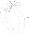
도 3은 본 발명의 휴대용 무선충전 전력공급장치가 특정한 휴대용 전자장비에 맞춤 제작된 경우에 본 발명의 휴대용 무선충전 전력공급장치와 휴대용 전자장비가 부착된 예를 도시한 도면이고, 도 4는 도 3의 단면도 중 외형 부분 및 코일 부분의 배치를 설명하기 위한 도면이다. 3 is a view illustrating an example in which the portable wireless charging power supply device and the portable electronic device of the present invention are attached when the portable wireless charging power supply device of the present invention is customized to a specific portable electronic device. FIG. It is a figure for demonstrating arrangement | positioning of an external part and a coil part among 3 cross sections.
도 3 및 도 4에서 예로 들은 휴대용 전자장비는 전자발찌의 한 종류로, 단면이 원으로 되어 있는 환의 형태로 구현되어 있다. 즉, 본 발명의 휴대용 무선충전 전력공급장치와 접하는 곳의 외부면의 단면이 곡선의 형태를 띠고 있다.3 and 4, the portable electronic device is an example of an electronic anklet, and is implemented in the form of a ring having a circular cross section. That is, the cross section of the outer surface of the contact with the portable wireless charging power supply of the present invention has a curved shape.
전자발찌(300)의 외부면이 곡면으로 되어 있기 때문에 충전본체부(100)에서 전자발찌(300)와 접하는 면(101)은 전자발찌(300)에 밀착되도록 곡선형으로 제작된다. Since the outer surface of the
또한, 고주파발생부(130)의 송신코일(131)은 충전본체부(100)에서 상기한 전자발찌(300)와 접하는 면(101) 쪽으로 배치되며, 송신 코일 역시 충전본체부(100)에서 상기한 전자발찌(300)와 접하는 면(101)을 따라서 설치가 된다. In addition, the
충전본체부(100)에서 휴대용 전자장비와 접하는 면을 평판형으로 제작하는 경우, 실제로 접하는 부분은 일부만이 되고 나머지 부분은 휴대용 전자장비와 거리가 멀어지게 되는데, 이렇게 되면 충전효율이 떨어지게 된다. When the surface of the charging
본 발명에서는 이러한 단점을 해결하기 위하여, 충전본체부(100)에서 휴대용 전자장비와 접하는 면이 휴대용 전자장비의 외부 면에 밀착되도록 형성되고, 고주파발생부(130)의 송신코일(131)이 그 접하는 면의 내측에 배치되도록 하고 있으며, 이를 통하여 충전효율을 극대화하고 있다. In the present invention, in order to solve this disadvantage, the surface in contact with the portable electronic equipment in the charging
도 5는 본 발명의 제1스트랩부 및 제2스트랩부의 일 실시예를 도시하고 있다. 5 shows an embodiment of the first strap portion and the second strap portion of the present invention.
제1스트랩부 및 제2스트랩부는 다양한 형상으로 구비될 수 있으며, 그 끝에는 결합부가 구비되어 서로 연결될 수 있도록 하는 것이 바람직하다. The first strap portion and the second strap portion may be provided in a variety of shapes, the end of the coupling portion is preferably provided to be connected to each other.
일 예로 도 5에 도시된 제1스트랩부(410) 및 제2스트랩부(420)에는 말단에 상기 제1스트랩부(410) 및 제2스트랩부(420)가 접하는 면이 서로 반대극성의 자석(411, 421)이 구비되도록 형성된 예를 도시한 것이다. For example, in the
도 6은 스트랩부의 또 다른 실시예를 도시한 것이다. Figure 6 shows another embodiment of the strap portion.
도 6의 스트랩부는 도 1에 도시된 바와 같이 제1스트랩부(510)에는 말단부위의 외부면에는 외부로 솟아난 돌기(511)가 구비되어 있고, 제2스트랩부(520)에는 상기한 돌기(511)가 삽입되어 고정될 수 있는 복수개의 홀(521, 522)이 구비되어 있어서 휴대용 전자장비의 크기에 따라서 제1스트랩부(510) 및 제2스트랩부(520)가 고정되는 위치를 변경할 수 있게 하고 있다. As shown in FIG. 1, the strap part of FIG. 6 is provided with a
또한, 제1스트랩부(510)에는 제2스트랩부(520)를 고정시키기 위한 밴드형태로 형성되어 내부에 제2스트랩부(520)를 삽입할 수 있도록 구현된 스트랩고정링(512)이 더 구비되어 제2스트랩부(520)의 말단이 단단히 고정되도록 한다. In addition, the
충전본체부 100 전원연결부 110
충전지부 120 고주파발생부 130
스위치부 140 충전표시부 150
제1스트랩부 210, 310, 410, 510
제2스트랩부 220, 320, 420, 520
전자발찌 300
자석 411, 412
돌기 511 홀 521, 522
스트랩고정링 512Charging
Claims (7)
상기 휴대용 전자장비의 무선충전을 위한 고주파신호를 발생시키는 충전본체부
상기 휴대용 전자장비가 상기 충전본체부에 밀착되어 고정되도록 하기 위한 밴드의 일부를 구성하기 위하여 상기 충전본체부의 일측면에 연결되고, 구부릴 수 있는 재질로 형성되며, 제1결합부를 포함하는 제1스트랩부 및
상기 밴드의 일부를 구성하기 위하여 상기 충전본체부의 타측면에 연결되고 구부릴 수 있는 재질로 형성되며, 제2결합부를 포함하는 제2스트랩부를 포함하고,
상기 제1스트랩부와 상기 제2스트랩부는 서로 분리될 수 있으며, 상기 제1스트랩부와 상기 제2스트랩부를 구부리는 경우 상기 제1결합부와 제2결합부가 서로 접하게 되며, 상기 제1결합부와 제2결합부를 통하여 상기 제1스트랩부 및 상기 제2스트랩부가 연결됨으로써 상기 휴대용 전자장비가 상기 충전본체부에 밀착되어 고정되고,
상기 휴대용 전자장비는 전자발찌인 것을 특징으로 하는 휴대용 무선충전 전력공급장치.In the portable wireless charging power supply for wirelessly charging portable electronic equipment that can be charged using an external high frequency signal,
Charging body unit for generating a high frequency signal for wireless charging of the portable electronic equipment
A first strap connected to one side of the charging body part and formed of a bendable material so as to form a part of a band for allowing the portable electronic device to be tightly fixed to the charging body part and formed of a bendable material; Wealth and
In order to form a part of the band is formed of a material connected to the other side of the filling body portion and bendable, including a second strap portion including a second coupling portion,
The first strap portion and the second strap portion may be separated from each other, and when the first strap portion and the second strap portion are bent, the first coupling portion and the second coupling portion are in contact with each other, the first coupling portion And the first strap part and the second strap part are connected to each other through the second coupling part to fix the portable electronic device in close contact with the charging body part.
The portable electronic device is a portable wireless charging power supply, characterized in that the electronic anklets.
외부의 전원과 연결되어 외부의 전원을 제공받기 위한 전원연결부;
상기 전원연결부를 통하여 공급되는 외부 전원을 이용하여 충전을 하는 충전지부;
상기 충전지부로부터 제공되는 전원을 이용하여 RF신호를 발생시키는 고주파발생부; 및
상기 충전지부로부터 공급되는 전원의 온 및 오프를 제어하기 위한 스위치부;를 포함하는 것을 특징으로 하는 휴대용 무선충전 전력공급장치.The method of claim 1, wherein the charging body portion
A power connection unit connected to an external power source to receive external power;
A rechargeable battery unit configured to charge using external power supplied through the power connection unit;
A high frequency generator generating an RF signal by using the power supplied from the rechargeable battery unit; And
Portable wireless charging power supply comprising a; switch for controlling the on and off of the power supplied from the rechargeable battery unit.
상기 충전지부가 충전되는 경우 상기 충전지부의 충전이 완료되었는지를 표시하기 위한 충전표시부;를 더 구비하는 것을 포함하는 것을 특징으로 하는 휴대용 무선충전 전력공급장치.The method of claim 2, wherein the charging body portion
And a charging display unit for indicating whether the charging unit is fully charged when the rechargeable battery unit is charged.
상기 제2결합부는 상기 제2스트랩부에 형성된 복수개의 홀이며, 상기 돌기가 상기 홀에 삽입됨으로써 상기 제1스트랩부 및 상기 제2스트랩부가 연결되어 고정되는 것을 특징으로 하는 휴대용 무선충전 전력공급장치.The method of claim 1, wherein the first coupling portion is a projection of a shape that rises on the outer surface of the first strap portion,
The second coupling portion is a plurality of holes formed in the second strap portion, the portable wireless charging power supply, characterized in that the projection is inserted into the hole is connected to the first strap portion and the second strap portion is fixed. .
Priority Applications (1)
| Application Number | Priority Date | Filing Date | Title |
|---|---|---|---|
| KR1020120015540A KR101364973B1 (en) | 2012-02-15 | 2012-02-15 | Portable apparatus for supplying power supply in wireless manner |
Applications Claiming Priority (1)
| Application Number | Priority Date | Filing Date | Title |
|---|---|---|---|
| KR1020120015540A KR101364973B1 (en) | 2012-02-15 | 2012-02-15 | Portable apparatus for supplying power supply in wireless manner |
Publications (2)
| Publication Number | Publication Date |
|---|---|
| KR20130094126A KR20130094126A (en) | 2013-08-23 |
| KR101364973B1 true KR101364973B1 (en) | 2014-02-19 |
Family
ID=49218092
Family Applications (1)
| Application Number | Title | Priority Date | Filing Date |
|---|---|---|---|
| KR1020120015540A Active KR101364973B1 (en) | 2012-02-15 | 2012-02-15 | Portable apparatus for supplying power supply in wireless manner |
Country Status (1)
| Country | Link |
|---|---|
| KR (1) | KR101364973B1 (en) |
Cited By (1)
| Publication number | Priority date | Publication date | Assignee | Title |
|---|---|---|---|---|
| KR20160074744A (en) | 2014-12-17 | 2016-06-29 | 재단법인 포항산업과학연구원 | Portable wireless power transfer instrument using the electromagnetic coupled resonance method |
Families Citing this family (4)
| Publication number | Priority date | Publication date | Assignee | Title |
|---|---|---|---|---|
| CN105814803B (en) | 2013-12-27 | 2019-02-01 | 阿莫绿色技术有限公司 | Wearable devices with flexible batteries |
| WO2015099514A1 (en) * | 2013-12-27 | 2015-07-02 | 주식회사 아모그린텍 | Wearable device having flexible battery |
| CN104113124A (en) * | 2014-08-04 | 2014-10-22 | 广东欧珀移动通信有限公司 | smart watch |
| CN105006945A (en) * | 2015-07-31 | 2015-10-28 | 梁金水 | Rotor structure power generation device applied to intelligent wristwatch |
Citations (2)
| Publication number | Priority date | Publication date | Assignee | Title |
|---|---|---|---|---|
| KR20030089875A (en) * | 2002-05-20 | 2003-11-28 | 최원기 | Portable Charge device of Mobile Phone |
| KR20100094977A (en) * | 2007-10-18 | 2010-08-27 | 위 유 엘엘씨 | Improved induction charger for portable battery-powered device |
-
2012
- 2012-02-15 KR KR1020120015540A patent/KR101364973B1/en active Active
Patent Citations (2)
| Publication number | Priority date | Publication date | Assignee | Title |
|---|---|---|---|---|
| KR20030089875A (en) * | 2002-05-20 | 2003-11-28 | 최원기 | Portable Charge device of Mobile Phone |
| KR20100094977A (en) * | 2007-10-18 | 2010-08-27 | 위 유 엘엘씨 | Improved induction charger for portable battery-powered device |
Cited By (1)
| Publication number | Priority date | Publication date | Assignee | Title |
|---|---|---|---|---|
| KR20160074744A (en) | 2014-12-17 | 2016-06-29 | 재단법인 포항산업과학연구원 | Portable wireless power transfer instrument using the electromagnetic coupled resonance method |
Also Published As
| Publication number | Publication date |
|---|---|
| KR20130094126A (en) | 2013-08-23 |
Similar Documents
| Publication | Publication Date | Title |
|---|---|---|
| CN203776266U (en) | Wireless charging and discharging wrist strap capable of replacing mobile phone | |
| CN104813420B (en) | Wireless charging system and method | |
| US10164468B2 (en) | Protective cover with wireless charging feature | |
| US8908479B2 (en) | Electronic wrist watch having wireless charging function | |
| KR102025889B1 (en) | Portable terminal, charging device, and charging structure thereof | |
| WO2014205383A1 (en) | Wearable mobile device charger | |
| CN103633706A (en) | Wireless rechargeable electronic bracelet and wireless charging method thereof | |
| WO2015137815A1 (en) | Arrangement of an electronic cigarette and a charger for wirelessly transferring power from the charger to the electronic cigarette, as well as an electronic cigarette and a charger for use in such an arrangement | |
| US20190237985A1 (en) | Wireless charging and docking system for mobile electronic devices | |
| US9331731B2 (en) | Wireless charge wristband-type mobile communication device | |
| KR20130094126A (en) | Portable apparatus for supplying power supply in wireless manner | |
| TWI264622B (en) | Electronic object of small dimensions capable of being worn on the wrist | |
| CN105186638A (en) | Wrist-mounted electronic equipment | |
| CN205657446U (en) | Wireless charging equipment | |
| US20110260674A1 (en) | Carrying case, portable electronic device, and electronic apparatus using the same | |
| CN104701957A (en) | Wireless charging wristband for smart watch | |
| KR20170003121A (en) | Wireless charging apparatus for portable terminal and wireless chargable portable terminal | |
| KR101932225B1 (en) | Wireless-chargable battery contained band and system for wirelessly charging battery of band | |
| CN204190476U (en) | Electronic equipment | |
| KR20140117185A (en) | Wireless charging apparatus having rechargable module, wire and wireless complex charing system | |
| KR102754496B1 (en) | Apparatus for charging auxiliary battery | |
| KR20140120786A (en) | ccc | |
| CN104917301A (en) | Electronic watch structure capable of realizing wireless charging | |
| CN205864081U (en) | The receiving terminal of wireless charging device | |
| CN215308164U (en) | Multifunctional physiotherapy old nursing device |
Legal Events
| Date | Code | Title | Description |
|---|---|---|---|
| A201 | Request for examination | ||
| PA0109 | Patent application |
St.27 status event code: A-0-1-A10-A12-nap-PA0109 |
|
| PA0201 | Request for examination |
St.27 status event code: A-1-2-D10-D11-exm-PA0201 |
|
| E902 | Notification of reason for refusal | ||
| PE0902 | Notice of grounds for rejection |
St.27 status event code: A-1-2-D10-D21-exm-PE0902 |
|
| T11-X000 | Administrative time limit extension requested |
St.27 status event code: U-3-3-T10-T11-oth-X000 |
|
| T11-X000 | Administrative time limit extension requested |
St.27 status event code: U-3-3-T10-T11-oth-X000 |
|
| E13-X000 | Pre-grant limitation requested |
St.27 status event code: A-2-3-E10-E13-lim-X000 |
|
| P11-X000 | Amendment of application requested |
St.27 status event code: A-2-2-P10-P11-nap-X000 |
|
| P13-X000 | Application amended |
St.27 status event code: A-2-2-P10-P13-nap-X000 |
|
| E902 | Notification of reason for refusal | ||
| PE0902 | Notice of grounds for rejection |
St.27 status event code: A-1-2-D10-D21-exm-PE0902 |
|
| PG1501 | Laying open of application |
St.27 status event code: A-1-1-Q10-Q12-nap-PG1501 |
|
| P11-X000 | Amendment of application requested |
St.27 status event code: A-2-2-P10-P11-nap-X000 |
|
| P13-X000 | Application amended |
St.27 status event code: A-2-2-P10-P13-nap-X000 |
|
| E701 | Decision to grant or registration of patent right | ||
| PE0701 | Decision of registration |
St.27 status event code: A-1-2-D10-D22-exm-PE0701 |
|
| GRNT | Written decision to grant | ||
| PR0701 | Registration of establishment |
St.27 status event code: A-2-4-F10-F11-exm-PR0701 |
|
| PR1002 | Payment of registration fee |
St.27 status event code: A-2-2-U10-U11-oth-PR1002 Fee payment year number: 1 |
|
| PG1601 | Publication of registration |
St.27 status event code: A-4-4-Q10-Q13-nap-PG1601 |
|
| PN2301 | Change of applicant |
St.27 status event code: A-5-5-R10-R13-asn-PN2301 St.27 status event code: A-5-5-R10-R11-asn-PN2301 |
|
| R18-X000 | Changes to party contact information recorded |
St.27 status event code: A-5-5-R10-R18-oth-X000 |
|
| FPAY | Annual fee payment |
Payment date: 20161205 Year of fee payment: 4 |
|
| PR1001 | Payment of annual fee |
St.27 status event code: A-4-4-U10-U11-oth-PR1001 Fee payment year number: 4 |
|
| P22-X000 | Classification modified |
St.27 status event code: A-4-4-P10-P22-nap-X000 |
|
| R18-X000 | Changes to party contact information recorded |
St.27 status event code: A-5-5-R10-R18-oth-X000 |
|
| FPAY | Annual fee payment |
Payment date: 20180205 Year of fee payment: 5 |
|
| PR1001 | Payment of annual fee |
St.27 status event code: A-4-4-U10-U11-oth-PR1001 Fee payment year number: 5 |
|
| FPAY | Annual fee payment |
Payment date: 20190110 Year of fee payment: 6 |
|
| PR1001 | Payment of annual fee |
St.27 status event code: A-4-4-U10-U11-oth-PR1001 Fee payment year number: 6 |
|
| P22-X000 | Classification modified |
St.27 status event code: A-4-4-P10-P22-nap-X000 |
|
| P22-X000 | Classification modified |
St.27 status event code: A-4-4-P10-P22-nap-X000 |
|
| FPAY | Annual fee payment |
Payment date: 20200205 Year of fee payment: 7 |
|
| PR1001 | Payment of annual fee |
St.27 status event code: A-4-4-U10-U11-oth-PR1001 Fee payment year number: 7 |
|
| PR1001 | Payment of annual fee |
St.27 status event code: A-4-4-U10-U11-oth-PR1001 Fee payment year number: 8 |
|
| P22-X000 | Classification modified |
St.27 status event code: A-4-4-P10-P22-nap-X000 |
|
| PR1001 | Payment of annual fee |
St.27 status event code: A-4-4-U10-U11-oth-PR1001 Fee payment year number: 9 |
|
| PR1001 | Payment of annual fee |
St.27 status event code: A-4-4-U10-U11-oth-PR1001 Fee payment year number: 10 |
|
| R18-X000 | Changes to party contact information recorded |
St.27 status event code: A-5-5-R10-R18-oth-X000 |
|
| R18-X000 | Changes to party contact information recorded |
St.27 status event code: A-5-5-R10-R18-oth-X000 |
|
| PR1001 | Payment of annual fee |
St.27 status event code: A-4-4-U10-U11-oth-PR1001 Fee payment year number: 11 |
|
| PR1001 | Payment of annual fee |
St.27 status event code: A-4-4-U10-U11-oth-PR1001 Fee payment year number: 12 |
|
| P22-X000 | Classification modified |
St.27 status event code: A-4-4-P10-P22-nap-X000 |
|
| P22-X000 | Classification modified |
St.27 status event code: A-4-4-P10-P22-nap-X000 |