KR101202419B1 - Device of LED lamp - Google Patents
Device of LED lamp Download PDFInfo
- Publication number
- KR101202419B1 KR101202419B1 KR1020120037702A KR20120037702A KR101202419B1 KR 101202419 B1 KR101202419 B1 KR 101202419B1 KR 1020120037702 A KR1020120037702 A KR 1020120037702A KR 20120037702 A KR20120037702 A KR 20120037702A KR 101202419 B1 KR101202419 B1 KR 101202419B1
- Authority
- KR
- South Korea
- Prior art keywords
- frame
- converter
- led
- led lighting
- coupled
- Prior art date
- Legal status (The legal status is an assumption and is not a legal conclusion. Google has not performed a legal analysis and makes no representation as to the accuracy of the status listed.)
- Expired - Fee Related
Links
Images


Classifications
-
- F—MECHANICAL ENGINEERING; LIGHTING; HEATING; WEAPONS; BLASTING
- F21—LIGHTING
- F21V—FUNCTIONAL FEATURES OR DETAILS OF LIGHTING DEVICES OR SYSTEMS THEREOF; STRUCTURAL COMBINATIONS OF LIGHTING DEVICES WITH OTHER ARTICLES, NOT OTHERWISE PROVIDED FOR
- F21V17/00—Fastening of component parts of lighting devices, e.g. shades, globes, refractors, reflectors, filters, screens, grids or protective cages
- F21V17/10—Fastening of component parts of lighting devices, e.g. shades, globes, refractors, reflectors, filters, screens, grids or protective cages characterised by specific fastening means or way of fastening
- F21V17/12—Fastening of component parts of lighting devices, e.g. shades, globes, refractors, reflectors, filters, screens, grids or protective cages characterised by specific fastening means or way of fastening by screwing
-
- F—MECHANICAL ENGINEERING; LIGHTING; HEATING; WEAPONS; BLASTING
- F21—LIGHTING
- F21S—NON-PORTABLE LIGHTING DEVICES; SYSTEMS THEREOF; VEHICLE LIGHTING DEVICES SPECIALLY ADAPTED FOR VEHICLE EXTERIORS
- F21S2/00—Systems of lighting devices, not provided for in main groups F21S4/00 - F21S10/00 or F21S19/00, e.g. of modular construction
- F21S2/005—Systems of lighting devices, not provided for in main groups F21S4/00 - F21S10/00 or F21S19/00, e.g. of modular construction of modular construction
-
- F—MECHANICAL ENGINEERING; LIGHTING; HEATING; WEAPONS; BLASTING
- F21—LIGHTING
- F21V—FUNCTIONAL FEATURES OR DETAILS OF LIGHTING DEVICES OR SYSTEMS THEREOF; STRUCTURAL COMBINATIONS OF LIGHTING DEVICES WITH OTHER ARTICLES, NOT OTHERWISE PROVIDED FOR
- F21V1/00—Shades for light sources, i.e. lampshades for table, floor, wall or ceiling lamps
- F21V1/02—Frames
- F21V1/04—Frames rigid
-
- F—MECHANICAL ENGINEERING; LIGHTING; HEATING; WEAPONS; BLASTING
- F21—LIGHTING
- F21V—FUNCTIONAL FEATURES OR DETAILS OF LIGHTING DEVICES OR SYSTEMS THEREOF; STRUCTURAL COMBINATIONS OF LIGHTING DEVICES WITH OTHER ARTICLES, NOT OTHERWISE PROVIDED FOR
- F21V1/00—Shades for light sources, i.e. lampshades for table, floor, wall or ceiling lamps
- F21V1/14—Covers for frames; Frameless shades
- F21V1/16—Covers for frames; Frameless shades characterised by the material
- F21V1/24—Covers for frames; Frameless shades characterised by the material the material being metal
-
- F—MECHANICAL ENGINEERING; LIGHTING; HEATING; WEAPONS; BLASTING
- F21—LIGHTING
- F21Y—INDEXING SCHEME ASSOCIATED WITH SUBCLASSES F21K, F21L, F21S and F21V, RELATING TO THE FORM OR THE KIND OF THE LIGHT SOURCES OR OF THE COLOUR OF THE LIGHT EMITTED
- F21Y2115/00—Light-generating elements of semiconductor light sources
- F21Y2115/10—Light-emitting diodes [LED]
Landscapes
- Engineering & Computer Science (AREA)
- General Engineering & Computer Science (AREA)
- Non-Portable Lighting Devices Or Systems Thereof (AREA)
Abstract
본 발명은 LED 조명장치에 관한 것으로, 구체적으로는 기존 형광등과 동일한 길이로 제작되어 기존 형광등을 대체하여 사용할 수 있으며, 복수의 등기구를 직렬 또는 병렬로 연결하여 사용할 수 있으므로 비교적 넓은 면적에서도 사용이 가능한 LED 조명장치에 관한 것이다.
본 발명은 형광등과 대응되는 길이로 형성되고, 상부에 안착면이 형성되며, 상기 안착면의 상부 가장자리 영역에 홈부가 형성되고, 상기 홈부의 하부 외측면 양측에 외측으로 소정각도 경사진 갓이 대칭형성되며, 상기 갓의 하부에는 중공부가 형성되어 그 내측에 컨버터가 내장되는 프레임; 상기 안착면에 열전도 접착제에 의하여 접착되는 LED 모듈; 상기 홈부에 결합되는 확산커버 및 상기 프레임의 양측단부와 결합되며, 상기 컨버터를 지지하는 마감부재를 포함한다.The present invention relates to an LED lighting device, specifically, the same length as the existing fluorescent lamp can be used to replace the existing fluorescent lamp, and can be used in a relatively large area because it can be used by connecting a plurality of luminaires in series or in parallel. It relates to an LED lighting device.
The present invention is formed in a length corresponding to the fluorescent lamp, the seating surface is formed on the upper portion, the groove is formed in the upper edge region of the seating surface, the shade is inclined outward at a predetermined angle on both sides of the lower outer surface of the groove portion is symmetrical A frame having a hollow portion formed at a lower portion of the shade, and having a converter embedded therein; An LED module bonded to the seating surface by a heat conductive adhesive; And a closing member coupled to both sides of the diffusion cover coupled to the groove and supporting both ends of the frame and supporting the converter.
Description
본 발명은 LED 조명장치에 관한 것으로, 구체적으로는 기존 형광등과 동일한 길이로 제작되어 기존 형광등을 대체하여 사용할 수 있으며, 복수의 등기구를 직렬 또는 병렬로 연결하여 사용할 수 있으므로 비교적 넓은 면적에서도 사용이 가능한 LED 조명장치에 관한 것이다.The present invention relates to an LED lighting device, specifically, the same length as the existing fluorescent lamp can be used to replace the existing fluorescent lamp, and can be used in a relatively large area because it can be used by connecting a plurality of luminaires in series or in parallel. It relates to an LED lighting device.
일반적으로 엘이디 전등은 형광등이나 백열등보다 에너지효율이 높고 수명이 길며, 특히 엘이디 전등의 광원으로 사용되는 엘이디 어레이모듈은 다수의 LED 소자로 구성되고 있다. 상기 엘이디 소자는 종래의 필라멘트 광원에 비해 발열량이 적고, 적은 소비전력과 긴 수명, 내충격성 등의 장점을 가지고 있음과 아울러, 형광등과 같이 수은이나 방전용 가스를 사용하지 않으므로 환경오염을 유발하지 않는 장점이 있으므로 최근 널리 사용되는 추세에 있다.In general, LED lamps have higher energy efficiency and longer life than fluorescent lamps or incandescent lamps. In particular, the LED array module used as a light source of LED lamps is composed of a plurality of LED elements. The LED device has less heat generation than conventional filament light sources, has the advantages of low power consumption, long life and impact resistance, and does not use mercury or discharge gas such as fluorescent lamps and thus does not cause environmental pollution. Because of its advantages, it has been widely used in recent years.
그런데, 상기 엘이디 소자를 이용한 전등에서 고휘도 고출력의 경제적인 조명용 광원을 얻기 위해서는 엘이디 소자에 구동전류를 증가시켜야 하나, 구동전류를 증가시키게 되면 전력손실이 증가 되어 대부분의 전기 에너지가 열로 변환되고 엘이디 소자의 접합부분이 고온상태로 된다. However, in order to obtain an economical light source having high brightness and high power in a lamp using the LED element, the driving current must be increased in the LED element. However, when the driving current is increased, power loss is increased and most electric energy is converted into heat and the LED element is increased. The junction part of becomes high temperature state.
엘이디 소자는 흐르는 전류가 일정하더라도 접합부분의 온도가 높아지면 광출력과 광효율이 저하될 뿐만 아니라 동작 수명도 줄어드는 특성이 있다. 따라서, 조명성능과 동작수명을 향상시키기 위해서는 엘이디 소자의 접합부분에서 발생되는 열을 최대한 빠르게 외부로 방출해 주어야 한다.Even if the current flowing through the LED device is constant, if the temperature of the junction increases, the light output and the light efficiency are not only reduced, but the operating life is also reduced. Therefore, in order to improve the lighting performance and operation life, the heat generated at the junction of the LED element should be discharged to the outside as soon as possible.
이와 같이 엘이디 소자를 광원으로 사용하는 엘이디 형광등은 방열문제만 해결하면 장시간 사용가능한 전등이지만, 엘이디 소자의 보호 및 엘이디 소자에서 발산되는 빛을 넓은 각도로 확산시켜주기 위해 사용하는 확산커버가 이물질에 오염되어 변질되면 밝기가 저하되어 엘이디 형광등 전체를 폐기하게 됨으로써 자원의 낭비를 가져왔다.The LED fluorescent lamp using the LED element as a light source can be used for a long time if only the heat dissipation problem is solved, but the diffusion cover used to protect the LED element and diffuse the light emitted from the LED element at a wide angle is contaminated with foreign substances. If it is changed, the brightness is lowered, and the entire LED fluorescent lamp is discarded, which causes a waste of resources.
또한, 엘이디를 이용한 형광램프를 사용하다 보면 기존의 형광등을 폐기하는 경우가 있는 데, 이에 본 출원인은 기존 형광등과 동일한 규격으로 제작하여 기존 형광등을 대체하여 사용할 수 있도록 다각적으로 고려하게 되었다. In addition, when using a fluorescent lamp using the LED, there is a case that the existing fluorescent lamp is discarded, and the present applicant has been considered in various ways so that the existing fluorescent lamp can be used to replace the existing fluorescent lamp.
이와 더불어 복잡하게 제작되고 있는 종래의 엘이디 형광등 대신에 좀 더 간단한 구조로 제작 및 조립할 수 있는 개량 엘이디 형광등의 프레임(방열몸체)과 확산커버를 강구할 수 있도록 다양한 형태로 개발하고 있다.In addition, instead of the conventional LED fluorescent lamps, which are being manufactured in a complicated manner, the LEDs have been developed in various forms so as to obtain a frame (heat radiating body) and a diffusion cover of an improved LED fluorescent lamp that can be manufactured and assembled in a simpler structure.
본 발명은 상기한 사정을 감안하기 위해 발명된 것으로, 그 목적은 기존의 형광등에 대응되는 LED 모듈을 구비하고, 상기 LED 램프가 결합되되 내부에 컨버터가 내장되는 알루미늄 재질의 프레임을 사용하여 기존의 형광등 및 등기구를 대용할 수 있는 LED 조명장치를 제공하는데 그 목적이 있다.The present invention was invented in view of the above circumstances, the object of which is provided with an LED module corresponding to the existing fluorescent lamp, the LED lamp is coupled to the existing using a frame made of an aluminum material with a converter built therein It is an object of the present invention to provide an LED lighting device that can replace fluorescent lamps and luminaires.
상기한 기술적 과제를 달성하기 위한 형광등과 대응되는 길이로 형성되고, 상부에 안착면이 형성되며, 상기 안착면의 상부 가장자리 영역에 홈부가 형성되고, 상기 홈부의 하부 외측면 양측에 외측으로 소정각도 경사진 갓이 대칭형성되며, 상기 안착면의 하부에는 중공부가 형성되는 프레임; 상기 중공부의 내측에 결합되되, 양단부에 컨버터 공이 형성되며, 상기 컨버터 공의 일측에 삽입홈이 형성되는 컨버터; 상기 안착면에 열전도 접착제에 의하여 접착되는 LED 모듈; 상기 홈부에 결합되는 확산커버 및 상기 프레임의 양측단부와 결합되고, 상기 컨버터를 지지하며, 전단부에 상기 컨버터 공과 대응되는 위치에 형성되는 관통공과, 상기 관통공의 내측영역에 형성되어 상기 삽입홈에 결합되는 고정부로 구성되되, 상기 관통공과 컨버터 공은 나사에 의해 결합되며, 상기 프레임을 둘 이상으로 구비하여 병렬배치용 커넥터를 통하여 병렬로 배치하거나 또는 직렬배치용 커넥터를 통하여 직렬로 배치하기 위한 연결용 단자가 양 외측면에 형성되는 마감부재를 포함한다.It is formed to a length corresponding to the fluorescent lamp for achieving the above technical problem, the seating surface is formed on the upper portion, the groove is formed in the upper edge region of the seating surface, the predetermined angle outward on both sides of the lower outer surface of the groove portion An inclined shade is formed symmetrically, and a frame having a hollow portion formed under the seating surface; A converter coupled to the inner side of the hollow part and having a converter ball formed at both ends thereof and having an insertion groove formed at one side of the converter ball; An LED module bonded to the seating surface by a heat conductive adhesive; A through hole coupled to the diffusion cover coupled to the groove and both end portions of the frame to support the converter, a through hole formed at a position corresponding to the converter hole at a front end portion, and an insertion groove formed in an inner region of the through hole; Comprising a fixed portion coupled to the through-hole and the converter ball is coupled by a screw, and having two or more of the frame to be arranged in parallel through the connector for parallel arrangement or to place in series through the connector for serial arrangement Connection terminal for includes a closing member formed on both outer surfaces.
삭제delete
일 실시예에 있어서, 상기 프레임은, 둘 이상의 프레임이 서로 병렬로 배치되도록 구성되되, 일체로 형성되는 것을 특징으로 한다.In one embodiment, the frame is configured so that two or more frames are arranged in parallel with each other, characterized in that formed integrally.
일 실시예에 있어서, 상기 갓은, 그 표면에 요철부를 더 포함한다.In one embodiment, the shade further includes an uneven portion on the surface.
본 발명의 LED 조명장치에 의하면, 첫째, 기존 형광등 및 등기구 대신에 적용할 수 있어 에너지효율이 우수하여 전력소모가 적고, 사용수명이 길어져 경제성이 높아지는 효과가 있다. According to the LED lighting device of the present invention, first, it can be applied in place of the existing fluorescent lamps and luminaires, the energy efficiency is excellent, the power consumption is low, the service life is long, the economic efficiency is increased.
둘째, 복수의 프레임을 직렬 또는 병렬로 배치하여 비교적 넓은 면적에서도 사용이 가능하므로 홍보용 간판 등에 널리 이용할 수 있다.Second, since a plurality of frames can be arranged in series or in parallel to be used in a relatively large area, it can be widely used for promotional signage.
셋째, 복수의 프레임을 길이방향에 대하여 일체로 형성함으로서 등기구가 둘 이상으로 필요한 장소에서도 프레임을 사용할 수 있으므로 제조비용을 절감할 수 있는 효과가 있다.Third, by forming a plurality of frames integrally with respect to the longitudinal direction, the frame can be used even in places where more than one luminaire is needed, thereby reducing the manufacturing cost.
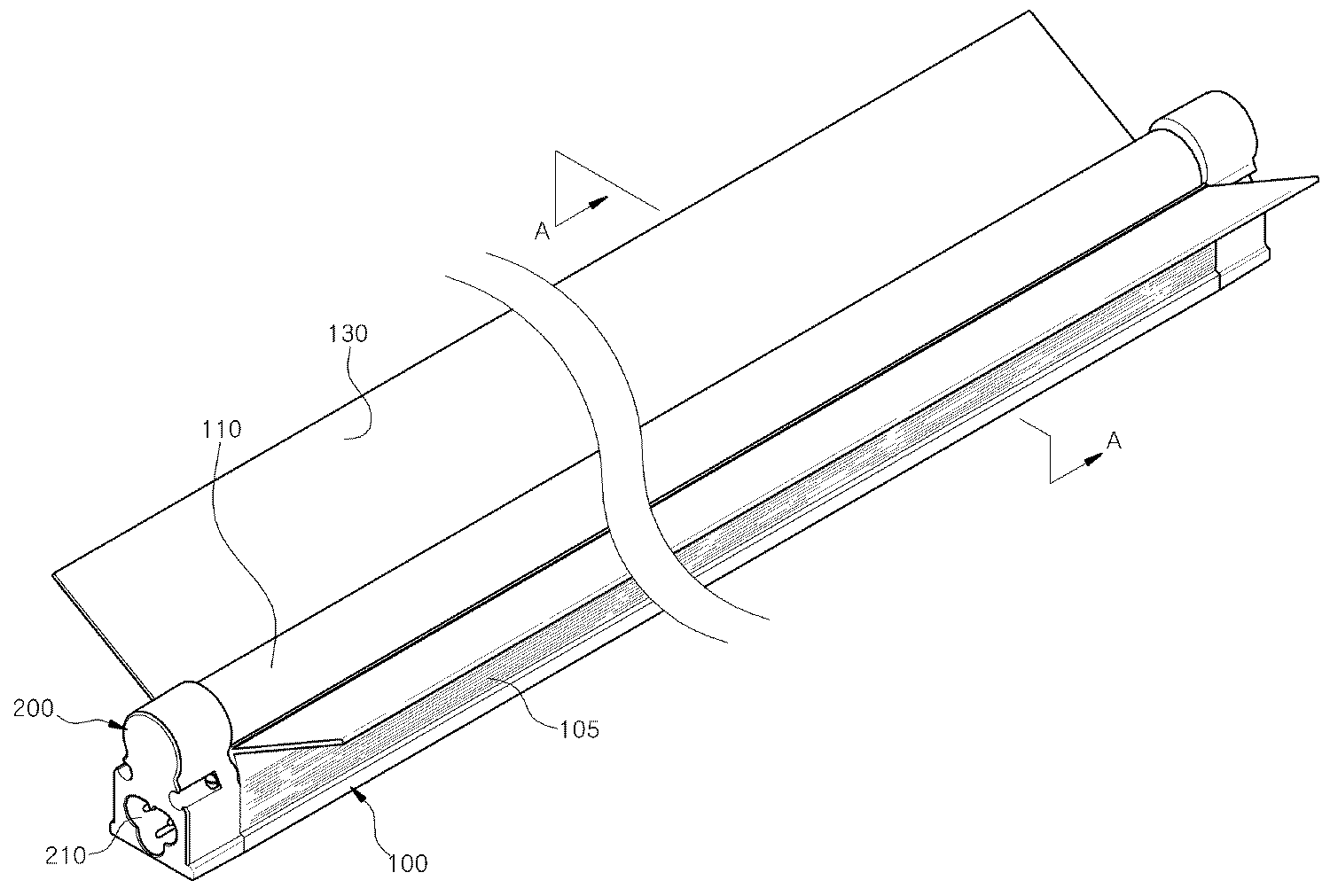
도 1은 본 발명의 LED 조명장치의 모습을 나타낸 사시도이다.
도 2는 도 1의 분해사시도이다.
도 3은 도 1의 A-A선 단면도이다.
도 4는 본 발명의 LED 램프 패지지가 직렬로 배치된 모습을 나타낸 도면이다.
도 5는 본 발명의 LED 조명장치가 병렬로 배치된 모습을 나타낸 도면이다.
도 6 및 도 7은 본 발명의 LED 조명장치에서 등기구의 변형예를 나타낸 도면이다.1 is a perspective view showing a state of the LED lighting apparatus of the present invention.
2 is an exploded perspective view of FIG. 1.
3 is a sectional view taken along the line AA in Fig.
4 is a view showing a state in which the LED lamp package of the present invention is arranged in series.
5 is a view showing a state in which the LED lighting apparatus of the present invention is arranged in parallel.
6 and 7 are views showing a modification of the luminaire in the LED lighting device of the present invention.
본 발명을 충분히 이해하기 위해서 본 발명의 바람직한 실시예를 첨부 도면을 참조하여 설명한다. 본 발명의 실시예는 여러 가지 형태로 변형될 수 있으며, 본 발명의 범위가 아래에서 상세히 설명하는 실시예로 한정되는 것으로 해석되어서는 안 된다. 본 실시예는 당업계에서 평균적인 지식을 가진 자에게 본 발명을 보다 완전하게 설명하기 위하여 제공 되는 것이다. 따라서 도면에서의 요소의 형상 등은 보다 명확한 설명을 강조하기 위해서 과장되어 표현될 수 있다. 각 도면에서 동일한 부재는 동일한 참조부호로 도시한 경우가 있음을 유의하여야 한다. 또한, 본 발명의 요지를 불필요하게 흐릴 수 있다고 판단되는 공지 기능 및 구성에 대한 상세한 기술은 생략된다.For a better understanding of the present invention, a preferred embodiment of the present invention will be described with reference to the accompanying drawings. The embodiments of the present invention may be modified into various forms, and the scope of the present invention should not be construed as being limited to the embodiments described in detail below. This embodiment is provided to more completely explain the present invention to those skilled in the art. Therefore, the shapes and the like of the elements in the drawings can be exaggeratedly expressed to emphasize a clearer description. It should be noted that in the drawings, the same members are denoted by the same reference numerals. In addition, detailed descriptions of well-known functions and configurations that are determined to unnecessarily obscure the subject matter of the present invention are omitted.
이하, 첨부된 도면을 참조하여 본 발명의 바람직한 실시예를 설명함으로써, 본 발명의 LED 조명장치를 상세히 설명한다.Hereinafter, by describing the preferred embodiment of the present invention with reference to the accompanying drawings, it will be described in detail the LED lighting device of the present invention.
도 1은 본 발명의 LED 조명장치의 모습을 나타낸 사시도이고, 도 2는 도 1의 분해사시도이며, 도 3은 도 1의 A-A선 단면도이고, 도 4는 본 발명의 LED 램프 패지지가 직렬로 배치된 모습을 나타낸 도면이며, 도 5는 본 발명의 LED 조명장치가 병렬로 배치된 모습을 나타낸 도면이고, 도 6 및 도 7은 본 발명의 LED 조명장치에서 등기구의 변형예를 나타낸 도면이다.1 is a perspective view showing a state of the LED lighting apparatus of the present invention, Figure 2 is an exploded perspective view of Figure 1, Figure 3 is a cross-sectional view taken along line AA of Figure 1, Figure 4 is a LED lamp package of the present invention in series Figure 5 is a view showing the arrangement, Figure 5 is a view showing a state in which the LED lighting device of the present invention arranged in parallel, Figures 6 and 7 is a view showing a modification of the luminaire in the LED lighting device of the present invention.
도 1 내지 도 7을 참조하면, 본 발명의 LED 조명장치는, 그 형상이 대략 사각기둥 형상으로 형성되며, 그 재질은 열 전도성이 뛰어난 알루미늄 재질로 형성되고, 기존에 사용되는 T5 형광등에 대응되는 길이로 형성되는 프레임(100)이 구비된다. 1 to 7, the LED lighting apparatus of the present invention, the shape is formed in a substantially rectangular pillar shape, the material is formed of an aluminum material excellent in thermal conductivity, corresponding to the conventional T5 fluorescent lamps The
상기 프레임(100)의 상부에는 LED 모듈(120)이 안착되도록 안착면(103)이 형성되고, 상기 안착면(103)에는 상기 LED 모듈(120)이 열전도 접착제에 의하여 접착된다. 상기 안착면(103)의 양측 가장자리 영역에는 상부로 소정길이 돌출되되 상단부가 움푹 파인 홈부(104)가 형성되며, 상기 홈부(104)에 확산커버(110)가 결합된다. 상기 안착면(103)의 상부 양측단에는 후술할 마감부재(200)가 나사(150)에 의해 체결되도록 상부 관통홀(101)이 형성된다. 상기 상부 관통홀(101)의 하부에는 후술할 결합봉(204)이 삽입되는 하부 관통홀(106)이 형성된다. A
또한, 상기 홈부(104)의 하부 외측면에 외측으로 소정각도 경사진 갓(130)이 형성되며, 상기 갓(130)의 하부에는 중공부(102)가 형성된다. 상기 중공부(102)는 그 내측에 컨버터(140)가 내장되며, 상기 컨버터(140)는 외부에서 공급되는 AC전압을 DC전압으로 변환하여 LED 모듈(120)에 전달하는 것으로, 양 측단부에는 삽입홈(142)이 형성되며, 상기 삽입홈(142)의 내측에는 컨버터 공(141)이 관통형성된다.In addition, the
한편, 상기 프레임(100)의 상부 양측에는 외측을 향하도록 소정각도로 경사진 갓(130)이 대칭 형성된다. 상기 갓(130)은 상기 LED 모듈(120)로부터 발광되는 빛을 소정각도로 발산시켜주는 역할 및 LED 모듈(120)에서 발생되는 열을 외부로 방출하는 역할을 하게 된다. 또한, 상기 갓(130)의 표면에는 전열면적으로 넓히기 위하여 요철부(131)가 형성되는데 이는 LED 모듈(120)에서 발생되는 열을 효과적으로 방출하기 위한 것이다.On the other hand, the
또한, 상기 프레임(100)의 외측면에도 전열면적으로 넓히기 위하여 요철부(105)가 형성되는데, 이 또한 LED 모듈(120)에서 발생되는 열을 효과적으로 방출하기 위한 것이다. In addition, the
따라서 갓(130)의 요철부(131) 및 프레임(100)의 요철부(105)를 통하여 LED 조명장치의 효과적인 냉각이 이루어지는 것이다.Therefore, effective cooling of the LED lighting device is achieved through the uneven portion 131 of the
상기 LED 모듈(120)은 메탈 PCB에 LED소자가 접합된 것으로, 메탈 PCB를 통하여 LED 소자에서 발생되는 열을 외부로 방출하며, 상기 메탈 PCB에서 전달되는 열이 상기 프레임(100)을 통하여 외부로 방출되는 것이다.The
상기 확산커버(110)는 그 단면의 형상이 대략 원형으로 형성되되, 일측이 절개되며, 절개된 양측 단부가 상기 홈부(104)에 길이방향으로 삽입된다. 또한, 상기 확산커버(110)는 엘이디 소자의 보호 및 엘이디 소자에서 발산되는 빛을 넓은 각도로 확산시켜주기 위해 사용되는 것으로, 불투명 또는 투명재질로 구성될 수 있다.
The
한편, 상기 프레임(100)의 양측 단부에는 상기 나사(150)에 의해 결합되는 마감부재(200)가 결합된다. On the other hand, both ends of the
상기 마감부재(200)는 내측에 상기 중공부(102)로 소정깊이 삽입되며, 상기 컨버터(140)와 결합되어 컨버터(140)를 지지하는 지지부재(201)가 형성된다. 상기 지지부재(201)의 전단부에는 관통공(202)이 형성되며, 상기 관통공(202)의 내측영역에는 고정부(203)가 형성되어 상기 컨버터(140)의 삽입홈(142)과 결합된다. 또한, 상기 관통공(202)은 상기 컨버터 공(141)과 대응되는 위치에 형성되며, 각각은 나사 또는 리브에 의해 결합되어 상기 지지부재(201)에 고정된다. The
상기 마감부재(200)의 외측면에는 연결용 단자(210)가 형성되는데, 이는 LED 조명장치 복수로 연결하여 사용할 때 커넥터(300)에 의하여 연결하여 사용하기 위한 것이다. 또한 상기 연결용 단자(210)의 상부 양측 가장자리 영역에는 관통홀(205)이 형성되는 상기 관통홀(205)을 통하여 나사(150)가 관통되어 프레임(100)의 상부 관통홀(101)에 결합되므로 마감부재(200)가 프레임(100)에 고정되는 것이다.
한편, 상기한 커넥터(300)는 두 가지 종류로 구분할 수 있는데, 병렬배치용 커넥터(300a)와 직렬배치용 커넥터(300b)로 구성된다. 도 4에 도시된 바와 같이 병렬로 배치하여 사용할 수 있으며, 도 5에 도시된 바와 같이 직렬로 배치하여 사용하기 위한 것이다.On the other hand, the connector 300 can be divided into two types, it is composed of a
한편, 본 발명의 LED 조명장치는 도 6 및 도 7에 도시된 바와 같이 둘 이상의 프레임(100)을 병렬로 배치되도록 하되 프레임(100)을 일체로 형성하여 사용할 수 있다. 그에 따라 LED 모듈(120)도 상기 프레임(100)의 수에 대응되도록 구비하여 사용할 수 있으며, 사용자의 필요에 따라 적절하게 그 개수를 조절할 수 있다.
On the other hand, the LED lighting device of the present invention, as shown in Figures 6 and 7 to be arranged in parallel with two or
이하, 상기와 같이 구성되는 본 발명의 LED 조명장치의 사용상태에 대하여 살펴보기로 한다. Hereinafter, the use state of the LED lighting device of the present invention configured as described above will be described.
도 4 및 5를 참조하면, 본 발명의 LED 조명장치는 간판 등과 같이 비교적 넓은 면적을 밝히고자 할 때 사용되는 것이다.4 and 5, the LED lighting device of the present invention is used to illuminate a relatively large area such as a sign.
도 4는 병렬로 프레임(100)을 배치한 후 내측에 전선이 구비되는 병렬배치용 커넥터(300a)를 연결하여 사용하는 것이고, 도 5는 프레임(200)의 마감부재(200)를 서로 접하도록 직렬로 배치하고, 상기 각각의 연결용 단자(210)에 직렬배치용 커넥터(300b)를 결합하여 사용하는 것이다.4 is used to connect the
또한, 도 7 및 도 8은 둘 이상의 프레임(100)을 일체로 형성한 예로서, 프레임(100)을 길이방향에 대하여 병렬로 배치되도록 일체로 형성하는 것이다.7 and 8 are examples in which two or
따라서 둘 이상의 LED 조명장치가 필요한 장소의 경우 하나의 프레임을 각각 설치하지 않아도 되어 설치비용의 감소 및 설치시간의 단축할 수 있다.Therefore, in the case where two or more LED lighting devices are required, each frame does not need to be installed, thereby reducing installation costs and shortening installation time.
이상에서 설명된 본 발명의 LED 조명장치의 실시예는 예시적인 것에 불과하며, 본 발명이 속한 기술분야의 통상의 지식을 가진 자라면 이로부터 다양한 변형 및 균등한 타 실시예가 가능하다는 점을 잘 알 수 있을 것이다. 그러므로 본 발명은 상기의 상세한 설명에서 언급되는 형태로만 한정되는 것은 아님을 잘 이해할 수 있을 것이다. 따라서 본 발명의 진정한 기술적 보호 범위는 첨부된 특허청구범위의 기술적 사상에 의해 정해져야 할 것이다. 또한, 본 발명은 첨부된 청구범위에 의해 정의되는 본 발명의 정신과 그 범위 내에 있는 모든 변형물과 균등물 및 대체물을 포함하는 것으로 이해되어야 한다.The embodiment of the LED lighting apparatus of the present invention described above is merely exemplary, and those skilled in the art will appreciate that various modifications and equivalent other embodiments are possible therefrom. Could be. Therefore, it is to be understood that the present invention is not limited to the above-described embodiments. Accordingly, the true scope of the present invention should be determined by the technical idea of the appended claims. It is also to be understood that the invention includes all modifications, equivalents, and alternatives falling within the spirit and scope of the invention as defined by the appended claims.
100 : 프레임 101 : 상부 관통홀
102 : 중공부 103 : 안착면
104 : 홈부 105 : 요철부
106 : 하부 관통홀 110 : 확산커버
120 : LED 모듈 130 : 갓
131 : 요철부 140 : 컨버터
141 : 컨버터 공 142 : 삽입홈
150 : 나사 200 : 마감부재
201 : 지지부재 202 : 관통공
203 : 고정부 204 : 결합봉
210 : 연결용 단자 300 : 커넥터100: frame 101: upper through hole
102
104: groove portion 105: uneven portion
106: lower through hole 110: diffusion cover
120: LED module 130: lampshade
131: uneven portion 140: converter
141: converter ball 142: insertion groove
150: screw 200: finishing member
201: support member 202: through hole
203: fixed portion 204: coupling rod
210: terminal for connection 300: connector
Claims (5)
상기 중공부(102)의 내측에 결합되되, 양단부에 컨버터 공(141)이 형성되며, 상기 컨버터 공(141)의 일측에 삽입홈(142)이 형성되는 컨버터(140);
상기 안착면(103)에 열전도 접착제에 의하여 접착되는 LED 모듈(120);
상기 홈부(104)에 결합되는 확산커버(110) 및
상기 프레임(100)의 양측단부와 결합되고, 상기 컨버터(140)를 지지하며, 전단부에 상기 컨버터 공(141)과 대응되는 위치에 형성되는 관통공(202)과, 상기 관통공(202)의 내측영역에 형성되어 상기 삽입홈(142)에 결합되는 고정부(203)로 구성되되, 상기 관통공(202)과 컨버터 공(141)은 나사에 의해 결합되며, 상기 프레임(100)을 둘 이상으로 구비하여 병렬배치용 커넥터(300a)를 통하여 병렬로 배치하거나 또는 직렬배치용 커넥터(300b)를 통하여 직렬로 배치하기 위한 연결용 단자(210)가 양 외측면에 형성되는 마감부재(200)를 포함하는 것을 특징으로 하는 LED 조명장치.It is formed to have a length corresponding to a fluorescent lamp, the seating surface 103 is formed on the upper portion, the groove portion 104 is formed in the upper edge region of the seating surface 103, and on both sides of the lower outer surface of the groove portion 104 A frame 100 in which a shade 130 inclined outward by a predetermined angle is symmetrically formed, and a hollow portion 102 is formed below the seating surface 103;
A converter 140 coupled to the inside of the hollow part 102 and having a converter ball 141 formed at both ends thereof, and having an insertion groove 142 formed at one side of the converter ball 141;
An LED module 120 adhered to the seating surface 103 by a heat conductive adhesive;
Diffusion cover 110 coupled to the groove portion 104 and
A through hole 202 coupled to both ends of the frame 100, supporting the converter 140, and formed at a front end at a position corresponding to the converter hole 141, and the through hole 202. It is formed in the inner region of the fixing portion 203 is coupled to the insertion groove 142, the through hole 202 and the converter ball 141 is coupled by a screw, the frame 100 Finishing member 200 is provided in the parallel arrangement via the parallel arrangement connector (300a) or the connection terminal 210 for placing in series through the series arrangement connector (300b) on both outer surfaces LED lighting apparatus comprising a.
상기 프레임(100)은,
그 외측면에 요철부(105)를 더 포함하는 것을 특징으로 하는 LED 조명장치.The method according to claim 1,
The frame 100,
LED lighting apparatus further comprises an uneven portion 105 on its outer surface.
상기 프레임(100)은,
둘 이상의 프레임(100)이 서로 병렬로 배치되도록 구성되되, 일체로 형성되는 것을 특징으로 하는 LED 조명장치.The method according to claim 1,
The frame 100,
Two or more frames 100 are configured to be arranged in parallel with each other, LED lighting device, characterized in that formed integrally.
상기 갓(130)은,
그 표면에 요철부(131)를 더 포함하는 것을 특징으로 하는 LED 조명장치.The method according to claim 1,
The shade 130 is,
LED lighting device further comprises a concave-convex portion (131) on its surface.
Priority Applications (1)
| Application Number | Priority Date | Filing Date | Title |
|---|---|---|---|
| KR1020120037702A KR101202419B1 (en) | 2012-04-12 | 2012-04-12 | Device of LED lamp |
Applications Claiming Priority (1)
| Application Number | Priority Date | Filing Date | Title |
|---|---|---|---|
| KR1020120037702A KR101202419B1 (en) | 2012-04-12 | 2012-04-12 | Device of LED lamp |
Publications (1)
| Publication Number | Publication Date |
|---|---|
| KR101202419B1 true KR101202419B1 (en) | 2012-11-16 |
Family
ID=47564884
Family Applications (1)
| Application Number | Title | Priority Date | Filing Date |
|---|---|---|---|
| KR1020120037702A Expired - Fee Related KR101202419B1 (en) | 2012-04-12 | 2012-04-12 | Device of LED lamp |
Country Status (1)
| Country | Link |
|---|---|
| KR (1) | KR101202419B1 (en) |
Cited By (1)
| Publication number | Priority date | Publication date | Assignee | Title |
|---|---|---|---|---|
| KR102568974B1 (en) * | 2023-03-08 | 2023-08-23 | 유한회사 하이에스텍 | Non-blot assembly LED lamp |
Citations (3)
| Publication number | Priority date | Publication date | Assignee | Title |
|---|---|---|---|---|
| KR100883345B1 (en) * | 2008-08-08 | 2009-02-12 | 김현민 | Line type LED lighting device |
| KR100946626B1 (en) | 2009-09-30 | 2010-03-09 | 주식회사 누리플랜 | Led lighting device |
| KR101024529B1 (en) * | 2009-09-30 | 2011-03-31 | (주) 디지라이트 | LED luminaires |
-
2012
- 2012-04-12 KR KR1020120037702A patent/KR101202419B1/en not_active Expired - Fee Related
Patent Citations (3)
| Publication number | Priority date | Publication date | Assignee | Title |
|---|---|---|---|---|
| KR100883345B1 (en) * | 2008-08-08 | 2009-02-12 | 김현민 | Line type LED lighting device |
| KR100946626B1 (en) | 2009-09-30 | 2010-03-09 | 주식회사 누리플랜 | Led lighting device |
| KR101024529B1 (en) * | 2009-09-30 | 2011-03-31 | (주) 디지라이트 | LED luminaires |
Cited By (1)
| Publication number | Priority date | Publication date | Assignee | Title |
|---|---|---|---|---|
| KR102568974B1 (en) * | 2023-03-08 | 2023-08-23 | 유한회사 하이에스텍 | Non-blot assembly LED lamp |
Similar Documents
| Publication | Publication Date | Title |
|---|---|---|
| CN107208849B (en) | Lighting module and lighting equipment including lighting module | |
| KR20110108269A (en) | LED lighting module and lighting lamp using the same | |
| KR101021722B1 (en) | Lighting equipment | |
| KR20090010850U (en) | Lighting device using LED as light source | |
| KR200456131Y1 (en) | LED floodlight | |
| KR101256865B1 (en) | Led lamp for lighting | |
| JP3163443U (en) | LED lighting device | |
| KR100921486B1 (en) | Fluorescent lamp type lighting device using high brightness light emitting diode | |
| KR101202412B1 (en) | LED lamp of FPL type | |
| KR20110062493A (en) | Indoor LED Auxiliary Light Case | |
| KR101202400B1 (en) | Led fluorescent lamp | |
| JP2012199163A (en) | Lighting device and lighting fixture | |
| KR101061218B1 (en) | Heat Sink for LED Lighting | |
| KR101608256B1 (en) | Light apparatus for multisystem with protection circuit | |
| US8789976B2 (en) | Integrated multi-layered illuminating unit and integrated multi-layered illuminating assembling unit | |
| KR200472771Y1 (en) | A light emitting diode lamp module and a streetlamp assembly using thereof | |
| KR101226040B1 (en) | Led light apparatus having the radiation of heat | |
| RU2474928C1 (en) | Light-emitting diode unit | |
| KR100938888B1 (en) | One body type led light apparatus | |
| KR101202420B1 (en) | Device of LED lamp | |
| KR101580256B1 (en) | light bulb type LED illumination device | |
| KR101089672B1 (en) | Expectation of mounting high power LED device and lighting device using it | |
| KR20120133056A (en) | Optical semiconductor based lighting apparatus | |
| KR101202408B1 (en) | Lighting device of LED | |
| KR101202406B1 (en) | Lighting device of LED |
Legal Events
| Date | Code | Title | Description |
|---|---|---|---|
| A201 | Request for examination | ||
| PA0109 | Patent application |
St.27 status event code: A-0-1-A10-A12-nap-PA0109 |
|
| PA0201 | Request for examination |
St.27 status event code: A-1-2-D10-D11-exm-PA0201 |
|
| A302 | Request for accelerated examination | ||
| PA0302 | Request for accelerated examination |
St.27 status event code: A-1-2-D10-D17-exm-PA0302 St.27 status event code: A-1-2-D10-D16-exm-PA0302 |
|
| D13-X000 | Search requested |
St.27 status event code: A-1-2-D10-D13-srh-X000 |
|
| D14-X000 | Search report completed |
St.27 status event code: A-1-2-D10-D14-srh-X000 |
|
| E902 | Notification of reason for refusal | ||
| PE0902 | Notice of grounds for rejection |
St.27 status event code: A-1-2-D10-D21-exm-PE0902 |
|
| R18-X000 | Changes to party contact information recorded |
St.27 status event code: A-3-3-R10-R18-oth-X000 |
|
| E13-X000 | Pre-grant limitation requested |
St.27 status event code: A-2-3-E10-E13-lim-X000 |
|
| P11-X000 | Amendment of application requested |
St.27 status event code: A-2-2-P10-P11-nap-X000 |
|
| P13-X000 | Application amended |
St.27 status event code: A-2-2-P10-P13-nap-X000 |
|
| E701 | Decision to grant or registration of patent right | ||
| PE0701 | Decision of registration |
St.27 status event code: A-1-2-D10-D22-exm-PE0701 |
|
| GRNT | Written decision to grant | ||
| PR0701 | Registration of establishment |
St.27 status event code: A-2-4-F10-F11-exm-PR0701 |
|
| PR1002 | Payment of registration fee |
St.27 status event code: A-2-2-U10-U11-oth-PR1002 Fee payment year number: 1 |
|
| PG1601 | Publication of registration |
St.27 status event code: A-4-4-Q10-Q13-nap-PG1601 |
|
| PN2301 | Change of applicant |
St.27 status event code: A-5-5-R10-R13-asn-PN2301 St.27 status event code: A-5-5-R10-R11-asn-PN2301 |
|
| P14-X000 | Amendment of ip right document requested |
St.27 status event code: A-5-5-P10-P14-nap-X000 |
|
| P16-X000 | Ip right document amended |
St.27 status event code: A-5-5-P10-P16-nap-X000 |
|
| Q16-X000 | A copy of ip right certificate issued |
St.27 status event code: A-4-4-Q10-Q16-nap-X000 |
|
| PN2301 | Change of applicant |
St.27 status event code: A-5-5-R10-R13-asn-PN2301 St.27 status event code: A-5-5-R10-R11-asn-PN2301 |
|
| FPAY | Annual fee payment |
Payment date: 20150803 Year of fee payment: 4 |
|
| PR1001 | Payment of annual fee |
St.27 status event code: A-4-4-U10-U11-oth-PR1001 Fee payment year number: 4 |
|
| P22-X000 | Classification modified |
St.27 status event code: A-4-4-P10-P22-nap-X000 |
|
| P22-X000 | Classification modified |
St.27 status event code: A-4-4-P10-P22-nap-X000 |
|
| LAPS | Lapse due to unpaid annual fee | ||
| PC1903 | Unpaid annual fee |
St.27 status event code: A-4-4-U10-U13-oth-PC1903 Not in force date: 20161113 Payment event data comment text: Termination Category : DEFAULT_OF_REGISTRATION_FEE |
|
| PC1903 | Unpaid annual fee |
St.27 status event code: N-4-6-H10-H13-oth-PC1903 Ip right cessation event data comment text: Termination Category : DEFAULT_OF_REGISTRATION_FEE Not in force date: 20161113 |
|
| P22-X000 | Classification modified |
St.27 status event code: A-4-4-P10-P22-nap-X000 |
|
| P22-X000 | Classification modified |
St.27 status event code: A-4-4-P10-P22-nap-X000 |