KR101159097B1 - Precast abutment for longitudinal continuous connection and construction method therefor - Google Patents
Precast abutment for longitudinal continuous connection and construction method therefor Download PDFInfo
- Publication number
- KR101159097B1 KR101159097B1 KR1020120031898A KR20120031898A KR101159097B1 KR 101159097 B1 KR101159097 B1 KR 101159097B1 KR 1020120031898 A KR1020120031898 A KR 1020120031898A KR 20120031898 A KR20120031898 A KR 20120031898A KR 101159097 B1 KR101159097 B1 KR 101159097B1
- Authority
- KR
- South Korea
- Prior art keywords
- wall portion
- rear wall
- front wall
- support block
- precast
- Prior art date
Links
Images


Classifications
-
- E—FIXED CONSTRUCTIONS
- E01—CONSTRUCTION OF ROADS, RAILWAYS, OR BRIDGES
- E01D—CONSTRUCTION OF BRIDGES, ELEVATED ROADWAYS OR VIADUCTS; ASSEMBLY OF BRIDGES
- E01D19/00—Structural or constructional details of bridges
- E01D19/02—Piers; Abutments ; Protecting same against drifting ice
-
- E—FIXED CONSTRUCTIONS
- E01—CONSTRUCTION OF ROADS, RAILWAYS, OR BRIDGES
- E01D—CONSTRUCTION OF BRIDGES, ELEVATED ROADWAYS OR VIADUCTS; ASSEMBLY OF BRIDGES
- E01D21/00—Methods or apparatus specially adapted for erecting or assembling bridges
-
- E—FIXED CONSTRUCTIONS
- E01—CONSTRUCTION OF ROADS, RAILWAYS, OR BRIDGES
- E01D—CONSTRUCTION OF BRIDGES, ELEVATED ROADWAYS OR VIADUCTS; ASSEMBLY OF BRIDGES
- E01D2101/00—Material constitution of bridges
- E01D2101/20—Concrete, stone or stone-like material
- E01D2101/24—Concrete
Abstract
Description
본 발명은 종방향으로 연속화가 가능한 프리캐스트 교대 및 그 시공방법에 관한 것이다. 더욱 구체적으로 종방향으로 다수의 배면 벽체부, 전면 벽체부를 설치하고 교대 상부 콘크리트를 통해 배면 벽체부, 전면 벽체부를 서로 일체화시켜 종방향으로 연속화된 교대를 시공할 수 있는 프리캐스트 교대 및 그 시공방법에 관한 것이다.The present invention relates to a precast shift that can be continuous in the longitudinal direction and a construction method thereof. More specifically, a precast shift and a construction method of installing a plurality of rear wall parts and a front wall part in the longitudinal direction and constructing a vertically continuous shift by integrating the rear wall part and the front wall part through alternating upper concrete with each other It is about.
통상 교대를 시공하기 위해서는 교대를 시공하기 위한 지반 터파기, 상기 터 파기된 지반 상면에 기초파일을 설치하고 교대구조물을 설치하고, 상기 교대구조물 배면공간을 뒷채움하는 방식으로 시공하게 된다.In order to construct a shift in general, ground excavation for the construction of the shift, the foundation pile is installed on the upper surface of the excavated ground, the shift structure is installed, and the construction is performed in such a manner as to fill the back space of the shift structure.
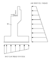
이때, 상기 교대구조물(10)은 도 1a와 같이 콘크리트로 제작된 교대구조물로 시공하는 것이 일반적이다.At this time, the
이에 상기 교대구조물은 되메움 되는 토사 등에 의한 토압(수평방향)을 받기 때문에 이러한 토압에 저항할 수 있도록 설계 및 제작되어 시공된다.Accordingly, the shift structure is designed, manufactured and constructed to resist such earth pressure because it receives earth pressure (horizontal direction) by backfilled earth and the like.
따라서 상기 교대구조물(10)은 시공되어야 하는 공간을 고려하여 교대구조물이 시공되는 부위를 상당량 터파기를 하게 된다. 말하자면 교대구조물이 설치되어야 할 공간을 미리 확보하고, 거푸집을 설치한 후 현장 타설콘크리트를 이용하여 시공하는 것이 일반적이다.Therefore, the
이에 성토부, 절토부, 단지 내 도로 양 측 지반 등에 있어 터파기를 통해 교대구조물을 시공하기 위한 노력 및 시간 역시 많이 요구되어 이를 해결하기 위하여 프리캐스트 교대구조물을 설치하기도 하지만,In order to solve this problem, a lot of effort and time are needed to construct the shift structure through the trench in the fill section, the cut section, and both sides of the road in the complex.
교대구조물의 높이가 커질 경우에는 작용하는 토압이 크기 때문에 교대구조물의 단면크기가 커질 수밖에 없어 프리캐스트 교대구조물 설치는 시공성 및 경제성 측면에서 해결해야 할 사항이 많다는 문제점이 있었다.When the height of the shift structure is increased, the cross-sectional size of the shift structure must be large because the earth pressure acting is large, and there is a problem that the installation of the precast shift structure has many problems to be solved in terms of constructability and economic efficiency.
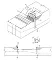
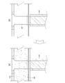
이를 해결하기 위하여 종래 소개된 교대 구조물 급속 시공방법을 살펴보면 도 1b 및 도 1c와 같이,Looking at the rapid construction method of the alternate structure introduced in order to solve this problem as shown in Figure 1b and 1c,
터파기한 지반에 교대용 기초파일(20)을 설치하되 그 상부가 지반 상방으로 연장되도록 설치하고, 상기 기초파일과 일체화되는 하부 교대구조물(11)을 설치함과 더불어 상기 터파기된 공간을 뒷채움 하되 상기 기초파일(20) 상부가 하부 교대구조물 상부로 돌출되도록 설치하고, Install the
상기 돌출된 기초파일 상부와 그 하부가 결합되는 접속파일(30)이 저면에 돌출 형성된 상부 교대구조물(12)을 설치하고, 상기 기초파일 상부와 접속파일에 의한 공간을 콘크리트를 포함하는 마감재로 마감하는 교대 구조물 급속 시공방법이 소개된 바 있다.The
이때 상기 하부 교대구조물(11)은 옹벽구조물로 시공되고, 상기 상부 교대구조물(12)은 접속파일(30)이 저면으로부터 돌출되도록 하는 블록 구조물로서, 접속파일(30)과 일체화된 프리캐스트 상부 교대구조물(12)을 이용하게 된다.In this case, the
이에 교대구조물의 효과적인 단면크기를 가지도록 설계할 수 있어 보다 경제적인 교대 구조물 시공이 가능하면서도, 보다 신속하게 교대구조물 시공을 가능하도록 하고 있음을 알 수 있다.This can be designed to have an effective cross-sectional size of the shift structure, it can be seen that the more economical shift structure construction, the faster the construction of the shift structure is possible.
하지만 상기 상부 교대구조물의 경우 프리캐스트 방식으로 제작한다고 할지라도 무게 때문에 제작 및 운반에 한계가 있어 제한적인 범위에서만 설치가능하게 된다는 한계가 있다.However, even if the upper shift structure is manufactured by the precast method, there is a limitation in that it can be installed only in a limited range due to the limitation in manufacturing and transportation due to the weight.
또한 종래 프리캐스트 교대구조물(프리캐스트 상부 교대구조물(12))의 경우 종방향으로 다수를 서로 연결시킬 경우 그 연속화 문제가 지적되는데 이러한 연속화 문제가 해결되지 않으면 각각의 프리캐스트 교대구조물 연결부에 하자가 발생할 수 있고 부등침하가 발생할 경우 대처하기가 쉽지 않다는 문제점이 있었다.In addition, in the case of the conventional precast shift structure (precast upper shift structure 12) when connecting the plurality in the longitudinal direction to each other, the sequencing problem is pointed out. If this continuity problem is not solved, each precast shift structure connection defect There was a problem that it may not be easy to cope with the occurrence of inequality.
이에 본 발명은 자중을 최소화시켜 공장제작한 프리캐스트 교대를 현장에 설치하되, 종방향으로 서로 연속화시킬 수 있어 일체로 거동할 수 있도록 함으로서 보다 구조적으로 효율적이고 경제적인 시공이 가능한 프리캐스트 교대 및 그 시공방법 제공을 그 해결하고자 하는 기술적 과제로 한다.Therefore, the present invention is to install the precast shift manufactured on the factory site by minimizing the self-weight, it can be continuous to each other in the longitudinal direction so that it can be integrated integrally precast shift and construction that can be more structurally efficient and economical Providing the construction method is the technical problem to be solved.
상기 기술적 과제를 달성하기 위하여In order to achieve the above technical problem
첫째 교대의 무게를 줄이기 위하여 중공 교대로 제작하기 위한 프리캐스트 벽체를 구비하고, 상기 프리캐스트 벽체를 현장에 설치한 후, 횡방향으로 서로 이격 설치된 프리캐스트 벽체의 상부에 교대 연속화콘크리트를 종방향으로 연속으로 형성시켜 상기 프리캐스트 벽체를 종방향으로 일체화시킴과 더불어 연속화 시키게 된다.In order to reduce the weight of the first shift, a precast wall is formed for alternating hollows, and after the precast wall is installed in the field, alternating sequential concrete is installed on the upper part of the precast wall spaced apart from each other in the lateral direction. It is formed continuously to integrate the precast wall in the longitudinal direction and to make it continuous.
둘째, 상기 횡방향으로 서로 이격 설치된 프리캐스트 벽체를 서로 연결시켜 주기 위하여 내부데크를 설치하게 되는데 이러한 내부데크 상부에는 내부데크 콘크리트를 타설하여 횡방향으로 서로 이격 설치된 프리캐스트 벽체를 서로 일체화시킴과 더불어 프리캐스트 벽체 배면에 작용하는 토압에 효과적으로 저항 할 수 있도록 하여 프리캐스트 벽체의 두께를 최소화시킬 수 있도록 하였다.Second, an inner deck is installed to connect the precast walls spaced apart from each other in the lateral direction. The inner deck is placed on top of the inner deck to integrate the precast walls spaced apart from each other in the lateral direction. The thickness of the precast wall can be minimized by effectively resisting the earth pressure acting on the back of the precast wall.
이를 위해 본 발명은To this end,
내측면에 상부 걸림지지블록이 형성된 배면 벽체부;A rear wall portion having an upper locking support block formed on an inner side thereof;
상기 배면 벽체부와 횡방향으로 이격 설치되는 것으로 배면 벽체부의 상부 걸림지지블록에 대응하는 위치에 상부 걸림지지블록이 내측면에 형성된 전면벽체부;A front wall portion having an upper locking support block formed on an inner side at a position corresponding to the upper locking support block of the rear wall portion to be spaced apart from the rear wall portion in a lateral direction;
상기 걸림지지블록들에 양 단부가 지지되도록 설치된 내부데크 및An inner deck installed at both ends of the engaging support blocks;
상기 내부데크 상부에 타설 및 양생되는 것으로서 배면 벽체부와 전면벽체부 상부 사이에 형성된 교대 연속화콘크리트;를 포함하여, 상기 배면 벽체부, 전면벽체부와 내부데크는 공장 제작되어 현장에서 설치되고, 상기 교대 연속화콘크리트는 현장타설 콘크리트로 직접 현장 시공되는 종방향으로 연속화가 가능한 프리캐스트 교대 및 그 시공방법을 제공한다.Alternate sequential concrete formed between the rear wall portion and the upper wall portion as being poured and cured on the inner deck; The rear wall portion, the front wall portion and the inner deck are factory manufactured and installed in the field. Alternating sequential concrete provides precast shifts and construction methods that can be sequential in the longitudinal direction, which is directly constructed with cast-in-place concrete.
또한, 종방향으로 형성된 배면 벽체부; 상기 배면 벽체부와 횡방향으로 이격 설치되는 것으로 배면 벽체부의 상면에 대응하는 위치에 종방향으로 형성된 전면벽체부; 상기 배면 벽체부와 전면벽체부의 상면에 양 단부가 지지되도록 설치된 내부데크; 및In addition, the rear wall portion formed in the longitudinal direction; A front wall part which is installed in a longitudinal direction at a position corresponding to an upper surface of the rear wall part and spaced apart from the rear wall part; An inner deck installed at both ends of the rear wall and the front wall to support both ends thereof; And
상기 배면 벽체부, 전면 벽체부와 내부데크 상부에 형성된 교대 연속화콘크리트;를 포함하여, 상기 배면 벽체부, 전면벽체부와 내부데크는 공장 제작되어 현장에서 설치되고, 상기 교대 연속화콘크리트는 현장타설 콘크리트로 직접 현장 시공되는 종방향으로 연속화가 가능한 프리캐스트 교대 및 그 시공방법을 제공한다.Alternate sequential concrete formed on the rear wall portion, the front wall and the inner deck; The rear wall portion, the front wall and the inner deck is factory-manufactured and installed in the field, the alternate sequential concrete is cast in place Provides a precast shift and its construction method that can be continuous in the longitudinal direction of the site.
본 발명에 의하여 운반 가능한 교대용 프리캐스트 벽체는 서로 일체화되어 종방향으로 연속화 시켜 구조적으로 연속성을 가진 교대 시공이 가능하게 된다.The alternating precast walls which can be transported by the present invention are integrated with each other to be continuous in the longitudinal direction, thereby enabling alternating construction having structural continuity.
또한 교대가 높이가 커지는 경우라 할지라도 내부데크에 의하여 교대에 작용하는 토압에 효과적으로 저항할 수 있어 교대의 대형화에 따른 교대의 구조적 안정성도 함께 확보할 수 있게 된다.In addition, even if the shift increases in height, it is possible to effectively resist the earth pressure acting on the shift by the internal deck, thereby ensuring the structural stability of the shift due to the increase of the shift.
본 발명의 범위는 상기 상세한 설명보다는 후술하는 특허청구범위에 의하여 나타내어지며, 특허청구범위의 의미 및 범위 그리고 그 균등 개념으로부터 도출되는 모든 변경 또는 변형된 형태가 본 발명의 범위에 포함되는 것으로 해석되어야 한다.The scope of the present invention is shown by the following claims rather than the above description, and all changes or modifications derived from the meaning and scope of the claims and their equivalents should be construed as being included in the scope of the present invention. do.
도 1a는 종래 교대의 사시도,
도 1b 및 도 1c는 종래 프리캐스트 교대의 시공 사시도 및 프리캐스트 상부 교대구조물의 발췌 사시도,
도 2a 및 도 2b는 본 발명의 연속화가 가능한 프리캐스트 교대의 시공사시도 및 정면도,
도 3a, 도 3b 및 도 3c는 본 발명의 연속화가 가능한 프리캐스트 교대 시공방법의 순서도,
도 4a 및 도 4b는 프리캐스트 벽체와 저판의 연결상세도,
도 5는 본 발명의 연속화가 가능한 프리캐스트 교대의 다른 시공사시도이다.1A is a perspective view of a conventional shift,
Figure 1b and Figure 1c is a perspective view of the construction of the conventional precast shift and the excerpt of the precast upper shift structure,
2A and 2B are construction views and front views of a precast shift capable of sequencing of the present invention;
3a, 3b and 3c is a flow chart of a precast shift construction method capable of sequencing of the present invention,
4a and 4b is a connection detail view of the precast wall and the bottom plate,
Fig. 5 is another constructional perspective view of the precast shift in which the present invention can be serialized.
아래에서는 첨부한 도면을 참조하여 본 발명이 속하는 기술분야에서 통상의 지식을 가진 자가 용이하게 실시할 수 있도록 본 발명의 실시예를 상세히 설명한다. 그러나 본 발명은 여러 가지 상이한 형태로 구현될 수 있으며 여기에서 설명하는 실시예에 한정되지 않는다. 그리고 도면에서 본 발명을 명확하게 설명하기 위해서 설명과 관계없는 부분은 생략하였으며, 명세서 전체를 통하여 유사한 부분에 대해서는 유사한 도면 부호를 붙였다.DETAILED DESCRIPTION Hereinafter, exemplary embodiments of the present invention will be described in detail with reference to the accompanying drawings so that those skilled in the art may easily implement the present invention. The present invention may, however, be embodied in many different forms and should not be construed as limited to the embodiments set forth herein. In the drawings, parts irrelevant to the description are omitted in order to clearly describe the present invention, and like reference numerals designate like parts throughout the specification.
[ 연속화가 가능한 프리캐스트 교대(A) ][Precast Shift (A)]
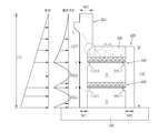
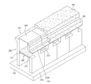
도 2a 및 도 2b는 본 발명의 종방향으로 연속화가 가능한 프리캐스트 교대의 시공사시도 및 정면도이다.2A and 2B are construction views and front views of a precast shift capable of being continuous in the longitudinal direction of the present invention.
상기 종방향으로 연속화가 가능한 프리캐스트 교대는 저판(100), 프리캐스트 벽체(200), 교대 연속화콘크리트(300) 및 내부데크(400)를 포함한다.The longitudinally continuous precast shift includes a
상기 저판(100)은 교대를 시공하기 위한 기초판으로 형성되는데 이러한 저판은 현장에서 소정의 두께로 현장 타설 콘크리트로 형성시키게 된다.The
이러한 저판(100)은 수평판 형태로 시공되는 부재로서 종방향으로 연속 시공하기가 수월하기 때문에 프리캐스트 방식으로 시공하는 것보다는 현장에서 거푸집을 이용하여 현장 타설 콘크리트로 형성시키게 된다.Since the
상기 저판(100)은 후술되는 프리캐스트 벽체(200)를 지지하기 위한 구조물인데 현장의 지반을 터파기 한 후 시공하면 된다.The
나아가 저판(100)을 설치하지 않더라도 프리캐스트 벽체(200)를 시공할 수 있다면 저판(100)의 생략은 가능할 것이므로 받침콘크리트를 포함하는 의미로 해석하기로 한다.Furthermore, even if the
상기 프리캐스트 벽체(200)는 교대의 전면부와 배면부를 구성하는 벽체로서 배면 벽체부(210) 및 전면벽체부(220)로 구분된다.The
먼저 상기 배면 벽체부(210)는 교대의 배면부를 형성시키기 위한 것으로서 수직벽체 형태로 제작 프리캐스트 제품이 이용된다.First, the
교대의 설치 높이(H1)에 따라 일체로 제작된 것이 이용되며 소정의 횡방향 폭(W1,W2)과 종방향 폭(W4)을 가진 철근콘크리트 수직 벽체이다.The one manufactured integrally according to the alternating installation height H1 is used and is a reinforced concrete vertical wall having a predetermined transverse width W1 and W2 and a longitudinal width W4.
이러한 배면 벽체부(210)는 공장에서 미리 제작된 것이 현장에 반입되어 수직으로 설치되는데 내부데크(400)를 설치하기 위하여 내측면에는 돌출 형성된 걸림블록이 형성되도록 하게 되며, The
상기 걸림블록은 종방향으로 연장된 블록으로 형성된다. 이러한 걸림블록은 적어도 상하로 1개 이상 설치되며, 각각 상부 걸림블록(212) 및 하부 걸림블록(211)로 구분되어 있음을 알 수 있다.The locking block is formed of a block extending in the longitudinal direction. At least one of these latching blocks is installed at least up and down, and it can be seen that they are divided into
이러한 배면 벽체부(210)는 하부의 횡방향 폭(W1)이 상부의 횡방향 폭(W2)보다 얇도록 형성되도록 할 수 있는데 이는 배면 벽체부(210)의 무게를 줄이면서 작용하는 하중에 효과적으로 저항할 수 있는 단면으로 형성시키기 위함이다.The
또한 배면 벽체부의 횡방향폭이 변화되는 상, 하부 경계부위(C)에는 테이퍼링되어 후술되는 교대 연속화콘크리트(300)가 형성되도록 하게 된다.In addition, the lateral width of the rear wall portion is changed, the lower boundary portion (C) is tapered to form an alternate
상기 전면 벽체부(220)는 교대의 전면부를 형성시키기 위한 것으로서 역시 수직벽체 형태로 제작 프리캐스트 제품이 이용된다.The
교대의 설치 높이에 따라 소정의 횡방향 폭(W3) 및 배면부 벽체와 동일한 종방향 연장길이를 가지도록 즉, 동일한 종방향 폭을 가진 철근콘크리트 수직 벽체이다.It is a reinforced concrete vertical wall having the same longitudinal width W3 and the same longitudinal extension as the rear wall, depending on the alternating installation height.
단지, 상기 전면 벽체부(220)의 높이(H2)는 배면 벽체부(210)의 높이(H1) 보다는 작은 높이로 형성되도록 하게 된다.However, the height H2 of the
이러한 전면 벽체부(220)도 역시 공장에서 미리 제작된 것이 현장에 반입되어 배면 벽체부(210)로부터 횡방향으로 이격되어 저판(100)에 수직으로 설치된다.The
역시 내부데크(400)를 설치하기 위하여 내측면에는 돌출 형성된 걸림블록이 상하로 형성되도록 하게 되며, 상기 걸림블록은 종방향으로 연장된 블록으로 형성되도록 하되 이러한 걸림블록은 배면 벽체부(210)에 형성된 상부 및 하부 걸림블록(212,211)의 위치에 대응하여 내측면에 적어도 상하로 1개 이상 설치시키게 된다.In order to install the
이에 역시 상기 전면 벽체부(220)의 걸림블록도 각각 상부 걸림블록(222) 및 하부 걸림블록(221)로 구분되어 있음을 알 수 있다.In addition, it can be seen that the locking block of the
이에 상기 배면 벽체부(210)와 전면 벽체부(220)의 횡방향 이격에 의하여 도 2b와 같이 교대의 내부중공(S)이 자연스럽게 형성되도록 할 수 있으며 각각의 걸림블록(211,221,212,222)들에는 내부데크(400)의 양 단부가 지지되도록 설치된다.Accordingly, the internal hollows S may be naturally formed as shown in FIG. 2B by the lateral separation of the
또한 상기 전면 벽체부(220)에는 자중을 줄이기 위하여 중공홀(223)을 형성시킬 수 있다.In addition, the
상기 내부데크(400)는 내부중공(S)에 설치되어 배면 벽체부(210)와 전면 벽체부(220)를 서로 구조적으로 일체화시키는 역할과 후술되는 교대 연속화콘크리트(300)를 형성시키기 위한 하부판으로의 역할을 하게 된다.The
먼저, 배면 벽체부(210)와 전면 벽체부(220)는 서로 횡방향으로 이격시켜 설치하기 때문에 서로 연결시켜 주지 않으면 일체화된 교대로 기능하지 못하므로 서로 연결시켜 주어야 한다.First, since the
이를 위해 통상의 수평판을 배면 벽체부(210)와 전면 벽체부(220) 사이에 설치하고 상기 수평판의 양 단부를 배면 벽체부(210)와 전면 벽체부(220)와 연결시켜 배면 벽체부(210)와 전면 벽체부(220)를 서로 연결시켜 줄 수도 있지만 일체화 성능이 떨어지게 된다.To this end, a normal horizontal plate is installed between the
이에 본 발명은 도 2a 및 도 2b와 같이 특히 내부데크(400)를 이용하게 되는데 이러한 내부데크(400)는 수평판 형태의 하판(410)과 상기 콘크리트 하판(410) 상면에 형성된 전단철근(420,레티스철근)이 일체로 형성된 것을 사용하게 된다.Accordingly, the present invention uses the
상기 하판(410)은 강재로 제작된 것을 이용해도 상관없으며 경제적인 면을 고려할 경우 콘크리트로 제작해도 상관은 없다.The
이러한 하판(410)은 앞서 살펴본 배면 벽체부(210)와 전면 벽체부(220)의 상부 걸림블록(211,221)에 양 단부가 지지되도록 횡방향 폭이 결정되고 종방향으로 배면 벽체부(210)와 전면 벽체부(220)의 종방향 폭(W4)에 맞추어 형성된 것을 이용하게 된다.The
상기 전단철근(420,레티스철근)은 하판과 일체화되어 상방으로 노출된 철근인데 이러한 전단철근(420,레티스철근)이 매립되도록 내부벽체(400) 상부에는 내부 데크콘크리트(430)가 타설된다.The shear reinforcing bar 420 (reticle reinforcing bar) is integrated with the lower plate and exposed upward. The
이에 상기 내부 데크콘크리트(430)가 전단철근(420)이 매립되도록 타설 후 양생되면 전단철근(420)에 의하여 하판(410)과 배면 벽체부(210) 및 전면 벽체부(220)가 서로 일체화되어 구조적으로 일체화된다.Accordingly, when the
따라서 배면 벽체부(210) 및 전면 벽체부(220)는 상기 내부데크(400)에 의하여 서로 구조적으로 일체화될 뿐만 아니라, 중요한 점은Therefore, the
상기 하부 걸림블록(211,221)과 내부데크(400)에 의하여 도 2b와 같이 배면 벽체부(210)의 배면에 작용하는 토압(V)에 대한 하중 지지점(P)이 추가로 형성된다는 점이다.The load supporting point P for the earth pressure V acting on the rear surface of the
즉, 배면 벽체부(210)의 높이(H1)는 교대에 따라 다르지만 개략 10M 정도라 보고 이러한 높이에 작용하는 배면 토압은 매우 커지게 되므로 특히 배면 벽체부(210)의 횡방향 폭(W1,W2)은 토압에 대응한 폭을 가져야 한다.That is, the height H1 of the
하지만 이러한 폭에 대응하는 배면 벽체부(210)를 제작하려면 횡방향 폭이 커짐에 따라 그 무게도 커질 수밖에 없어 프리캐스트로 배면 벽체부(210)를 제작하기에 한계가 있게 된다.However, in order to manufacture the
이에 상기 배면 토압이 배면 벽체부(210)의 높이에 따라 커진다는 점을 고려하여 높이 중간 지점에 하중 지지점(P)을 형성시키게 되면 상기 하중 지지점(P)를 기준으로 배면 벽체부(210)의 높이는 (H11,H12,H13)로 구분되어 전면 벽체부(220)에 작용하는 휨 모멘트는 상하로 보다 작은 크기로 작용됨을 알 수 있다.Accordingly, when the load supporting point P is formed at the middle point of the height in consideration of the fact that the rear earth pressure increases with the height of the
따라서 배면 벽체부의 횡방향 폭(W1)은 상하로 작은 토압에 대응하여 형성시킬 수 있어 그 무게를 최소화 시킬 수 있게 된다.Therefore, the transverse width W1 of the rear wall portion can be formed corresponding to the small earth pressure up and down, thereby minimizing its weight.
이에 상기 하중지지점(P)들이 하부 걸림블록(211,221)과 내부데크(400)에 의하여 형성될 수 있도록 함으로서 전면 벽체부(220)의 높이(H)에 따른 횡방향 폭을 크게 증가시키지 않을 수 있게 됨을 알 수 있다.Accordingly, the load supporting points P may be formed by the lower locking blocks 211 and 221 and the
상기 교대 연속화콘크리트(300)는 교대 상부를 서로 종방향으로 연속화된 구조체로 형성시키기 위한 것이다.The alternating
즉, 상기 프리캐스트 벽체(200)의 상부 걸림블록(212,222)에는 교대 연속화콘크리트(300)가 형성된다.That is, alternating
교대 상부는 예컨대 교대가 철도용인가 아니면 교량용인가에 따라 용도가 구분된다. 하지만 어떤 용도이든지 간에 교대 상면은 받침이 설치되는 등 통행하중이 반복이 계속되는 부위이다.The upper part of the shift is classified according to whether the shift is for railway or bridge, for example. However, whatever the use, the alternating upper surface is the part where the traffic load repeats, such as the support.
이에 상기 반복 하중에 의하여 피로하중이 매우 커지기 때문에 교대가 세그먼트화 될 경우 종방향 연결부에 문제가 발생할 수 있다.As a result, the fatigue load becomes very large due to the repetitive load, which may cause a problem in the longitudinal connection when the shift is segmented.
설사 종방향 연결부에 문제가 발생하지 않는다고 하더라도 추후 연결부의 유지관리가 쉽지 않게 된다.(부등침하등)Even if the longitudinal connection does not cause problems, maintenance of the connection is not easy in the future.
이에 본 발명은 교대 상부는 종방향으로 연속화된 구조체로 형성시키게 되며 이는 현장에서 교대 상부를 콘크리트로 일체로 형성시키게 된다.In the present invention, the alternating upper portion is formed as a continuous structure in the longitudinal direction, which is to form the alternating upper portion integrally with concrete in the field.
하지만 본 발명의 교대는 배면 벽체부(210) 및 전면 벽체부(220)가 서로 횡방향으로 이격되어 있으므로 상부에 역시 앞서 살펴본 내부데크(400)를 배면 벽체부(210) 및 전면 벽체부(220)의 상부 걸림블록(212,222)에 양 단부가 지지되도록 설치하게 된다.However, since the
물론 상기 내부데크(400)는 교대 연속화콘크리트(300)를 타설하기 위한 하판으로 작용함을 알 수 있다. 물론 앞서 살펴본 것과 같이 배면 벽체부(210) 및 전면 벽체부(220)를 서로 일체화시켜 주는 역할을 함께 하게 되며 하중 지지점(P)의 역할도 하게 된다.Of course, it can be seen that the
또한 상기 내부데크(400)는 수평판 형태의 하판(410)과 상기 콘크리트 하판(410) 상면에 형성된 전단철근(420,레티스철근)이 일체로 형성된 것을 이용할 수 있을 것이다.In addition, the
이에 상기 내부데크(400)가 설치되면 교대 연속화콘크리트(300)용 콘크리트를 타설하게 되는데, 이러한 교대 연속화콘크리트(300)는 상부 및 하부 전면 벽체부(222,123)의 경계에 위치하도록 하고 상면은 외부에 노출되도록 형성시키게 된다.When the
상기 교대 연속화콘크리트(300)의 타설 높이는 상기 반복하중에 대응하는 충분한 상하 두께를 가지도록 하게 되며, 이러한 교대 연속화콘크리트(300)는 종방향으로 배면 벽체부(210) 및 전면 벽체부(220)가 모두 설치된 상태에서 일체로 형성시켜 교대 상부가 서로 일체화되도록 하게 된다.The placing height of the alternate
이로서 본 발명의 프리캐스트 벽체(200)는 내부중공(S)이 형성되어 있어 배면 벽체부(210) 및 전면 벽체부(220)의 무게를 최소화하면서도 서로 구조적으로 일체화시킬 수 있고, 전면 벽체부(220)에 작용하는 토압에 대하여 효과적으로 저항할 수 있어 매우 효율적인 프리캐스트 교대 시공이 가능하게 됨을 알 수 있다.As a result, the
[ 연속화가 가능한 프리캐스트 교대(A) 시공방법 ][Construction method of precast shift (A) that can be serialized]
도 3a 내지 도 3c는 본 발명의 연속화가 가능한 프리캐스트 교대(A) 시공방법을 순서대로 도시한 것이다.3A to 3C sequentially illustrate a method of constructing a precast shift A that can be serialized according to the present invention.
먼저 도 3a와 같이 교대가 설치되어야 현장의 지반을 터파기하고 마감하고 저판(100)을 형성시키게 된다.First, as shown in FIG. 3a, the shift is to be broken and finished the ground of the site and to form the
상기 저판(100)은 거푸집을 이용하여 소정의 두께를 가진 수평판 형태로 형성시키면 되고 철근콘크리트 저판을 현장에서 시공하게 된다.The
이러한 저판(100) 상면에는 배면 벽체부(210) 및 전면 벽체부(220)의 하부가 연결될 수 있도록 서로 강결시킬 수 도 있고 힌지 연결(미도시)시킬 수도 있다.The
먼저, 도 4a 및 도 4b는 특히 저판(100)과 배면 벽체부(210) 및 전면 벽체부(220) 즉 프리캐스트 벽체(200)를 서로 강결시키는 예가 도시되어 있다.First, FIGS. 4A and 4B show an example in which the
먼저, 도 4a를 기준으로 살펴보면, 프리캐스트 벽체(200)의 내부철근(230)을 하방으로 연장하여 저판(100)을 시공할 때 매립되도록 배치하게 된다.First, referring to FIG. 4A, the
이이에 상기 내부철근이 하방으로 연장되어 세팅된 프리캐스트 벽체(200)가 세팅되면 저판용 내부철근을 배근하고, 저판용 콘크리트(110)를 소정의 두께로 형성시켜 상기 프리캐스트 벽체(200)와 저판(100)을 서로 일체화시켜 강결시킬 수 있다.In this case, when the
도 4b는 현장타설된 콘크리트로 제작된 저판(100)의 내부철근(120)에 프리캐스트 벽체(200)를 슬리브를 이용하여 서로 강결시키는 예이다.Figure 4b is an example of using the sleeve to the
즉, 상기 프리캐스트 벽체(200) 저면에 매립 형성된 슬리브(240)의 내부에 내부철근(230)이 미리 삽입(개략 절반 정도)도록 세팅하고,That is, the internal reinforcing
상기 저판(100)의 내부철근(120)도 상기 슬리브(240)에 하부로부터 삽입되도록 한 후, 상기 슬리브 내부에 그라우팅재로 인하여After the
상기 저판의 내부철근(120)이 슬리브(240)에 의하여 프리캐스트 벽체(200)와 서로 일체화되도록 하여 강결시킬 수 있다.The
이에 상기 저판(100)의 외측상면에 먼저 공장에서 제작되어 현장에 반입된 배면 벽체부(210)를 먼저 설치하게 된다.Accordingly, the
이러한 배면 벽체부(210)는 종방향으로 서로 접하도록 하고 연결부는 그라우팅 하는 등의 종방향 연결을 저판에 자립할 수 있도록 설치된다.The
다음으로 상기 배면 벽체부(210)와 횡방향을 이격되도록 저판(100) 내측상면에 전면 벽체부(220)를 설치하게 된다.Next, the
물론 상기 전면 벽체부(220)도 공장에서 제작되어 현장에 반입된 배면 벽체부(210)를 먼저 설치하게 된다.Of course, the
이러한 전면 및 배면 벽체부(110,120)의 내측면에는 걸림지지블록(211,212,221,222)이 중간 및 상부에 각각 형성되어 내부데크(400)를 상하로 설치할 수 있도록 함을 알 수있다.On the inner side of the front and rear wall portion (110, 120) it can be seen that the engaging support blocks 211, 212, 221, 222 are formed in the middle and top, respectively, so that the
다음으로는 도 3b와 같이 상기 전면 및 배면 벽체부(110,120)에 형성된 하부 걸림지지블록(211,221)에 내부데크(400)가 지지되도록 설치하게 된다.Next, as shown in Figure 3b is installed so that the
먼저 아래쪽 내부데크(400)를 종방향으로 서로 접하도록 설치한 후 내부 데크콘크리트(430)가 타설 및 양생시키고, 위쪽 내부데크(400)를 역시 종방향으로 서로 접하도록 설치하게 된다.First, the lower
이에 먼저 도 3c와 같이 하부 걸림지지블록(211,221)에 내부데크(400) 상부에 내부 데크콘크리트(430)를 타설하여 양생시켜 전면 및 배면 벽체부(110,120)를 서로 일체화시키게 된다.First, as shown in FIG. 3c, the
다음으로는 상기 상부 걸림지지블록(212,222)에 설치된 내부데크(400)에 교대 연속화콘크리트(300)용 콘크리트를 타설 및 양생시켜 교대 연속화콘크리트(300)를 종방향으로 일체로 타설하게 된다.Next, the concrete for alternating
이로서 간단하게 프리캐스트 방식으로 하되 서로 구조적으로 일체화된 교대(A)를 시공할 수 있게 됨을 알 수 있다.As a result, it can be seen that it is possible to construct a shift A that is simply structurally integrated with each other in a precast manner.
[ 연속화가 가능한 프리캐스트 교대의 다른 실시예 ][Other Embodiments of Precast Shift Enabled for Continuous]
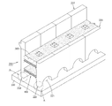
도 5는 특히 도 2a 및 도 2b의 프리캐스트 교대와 유사하지만 내부데크(400) 및 전면벽체부(220)의 다른 형태가 도시되어 있다.FIG. 5 is particularly similar to the precast alternating of FIGS. 2A and 2B but shows other forms of the
즉, 배면 벽체부(210)는 하부 걸림블록(211)이 형성된 수직벽체로 형성되어 있음을 알 수 있으며,That is, it can be seen that the
전면 벽체부(220)는 상기 하부 걸림블록(211)에 대응하는 하부 걸림블록(221)이 형성된 수직벽체로 형성되어 있음을 알 수 있다.It can be seen that the
이때 상기 전면 벽체부(220)는 크기 등을 고려하여 상부 및 하부 전면 벽체부(220a,220b)로 구분 제작하여 설치할 수 있다.In this case, the
예컨대, 상면에 수직기둥부가 형성된 하부 전면 벽체부(220b)를 종방향으로 연결시켜 설치하고,For example, the lower
전체적으로 단면의 상부 전면 벽체부(220a)를 상기 하부 전면 벽체부(220b) 상면에 얹어지도록 세팅시킬 수 있다.The upper
이때 상기 단면의 상부 전면 벽체부(220a)가 전도 되지 않도록 버텀대(미도시)를 더 설치할 수 있을 것이다.At this time, a bottom (not shown) may be further installed so that the upper
또한, 상기 배면 벽체부(210)와 전면 벽체부(200) 또는 상부 전면 벽체부(200b)의 상면 사이에 내부데크(400)를 설치하게 된다.In addition, an
이러한 내부데크(400)는 앞서 살펴본 것과 같이 하판(410)과 전단연결재(420)를 사용할 수 있으나 수평판 형태로 형성된 것을 이용해도 상관없으며 도 5에는 내부데크(400)가 양 단부가 하방으로 절곡된 수평판이 이용되도록 함을 알 수 있다.The
역시 상기 배면 벽체부와 전면 벽체부의 하부 걸림지지블록(211,221) 사이에는 하판(410)과 전단연결재(420)를 이용하여 제작된 내부데크(400)를 사용함을 알 수 있다.It can also be seen that the
나아가 교대 연속화콘크리트(300)는 배면 벽체부(210), 전면 벽체부(220) 및 수평판 형태의 내부데크(400)의 상부에 형성시키거나,Furthermore, the alternate
배면 벽체부(210), 상부 전면 벽체부(220a) 및 수평판 형태의 내부데크(400)의 상부에 형성시킬 수 있게 된다.The
또한 상부 및 하부 전면벽체부(220a,220b)도 추가로 교대 연속화콘크리트(300)를 이용하여 서로 일체화시켜 연속화 시킬 수 있음을 알 수 있다.In addition, it can be seen that the upper and lower
100: 저판
200: 프리캐스트 벽체
210: 배면 벽체부
211: 하부 걸림지지블록
212: 상부 걸림지지블록
220: 전면 벽체부
221: 하부 걸림지지블록
222: 상부 걸림지지블록
300: 교대 연속화콘크리트
400: 내부데크
410: 하판
420: 전단철근
430: 내부 데크콘크리트100: bottom plate
200: precast wall
210: back wall part
211: lower locking support block
212: upper locking support block
220: front wall
221: lower locking support block
222: upper locking support block
300: alternate sequential concrete
400: internal deck
410: bottom plate
420: shear rebar
430: internal deck concrete
Claims (14)
상기 배면 벽체부(210)와 횡방향으로 이격 설치되는 것으로 배면 벽체부(210)의 상부 걸림지지블록(212)에 대응하는 위치에 상부 걸림지지블록(222)이 내측면에 종방향으로 형성된 전면벽체부(220);
상기 걸림지지블록(212,222)들에 양 단부가 지지되도록 설치된 내부데크(400); 및
상기 내부데크(400) 상부의 배면 벽체부(210)와 전면벽체부(220) 상부 사이에 형성된 교대 연속화콘크리트(300);를 포함하여,
상기 배면 벽체부(210), 전면벽체부(220)와 내부데크(400)는 공장 제작되어 현장에서 설치되고, 상기 교대 연속화콘크리트(300)는 현장타설 콘크리트로 직접 현장 시공되는 것을 특징으로 하는 종방향으로 연속화가 가능한 프리캐스트 교대.A rear wall portion 210 in which an upper locking support block 212 is formed in a longitudinal direction on an inner side thereof;
The front wall is formed to be spaced apart from the rear wall portion 210 in the transverse direction, the upper locking support block 222 in the position corresponding to the upper locking support block 212 of the rear wall portion 210 in the longitudinal direction on the inner surface Wall portion 220;
An inner deck 400 installed at both ends of the engaging support blocks 212 and 222 to support the ends; And
Including; alternating sequential concrete 300 formed between the rear wall portion 210 and the front wall portion 220 of the upper portion of the inner deck 400;
The rear wall portion 210, the front wall portion 220 and the inner deck 400 is factory-manufactured and installed in the field, the alternating continuous concrete 300 is characterized in that the construction of the site directly in the cast concrete Precast shift that can be continuous in any direction.
상기 배면 벽체부(210)의 상부 걸림지지블록(212) 하방으로 하부 걸림지지블록(211)이 내측면에 종방향으로 더 형성되며, 상기 전면 벽체부(220)의 상부 걸림지지블록(221) 하방으로 하부 걸림지지블록(221)이 배면 벽체부의 하부 걸림지지블록(211)의 위치에 대응하여 내측면에 종방향으로 더 형성되어,
상기 하부 걸림지지블록들(211,221)에 내부데크(400)가 더 설치되어 상기 내부데크(400) 상부에 내부 데크콘크리트(430)가 더 형성되도록 하는 것을 특징으로 하는 종방향으로 연속화가 가능한 프리캐스트 교대.The method of claim 1,
The lower locking support block 211 is further formed in the longitudinal direction below the upper locking support block 212 of the rear wall portion 210, and the upper locking support block 221 of the front wall portion 220. The lower locking support block 221 is further formed in the longitudinal direction on the inner side corresponding to the position of the lower locking support block 211 in the rear wall,
An inner deck 400 is further installed on the lower locking support blocks 211 and 221 so that the inner deck concrete 430 may be further formed on the inner deck 400. rotation.
상기 내부데크(400)는 하판(410)과 상기 콘크리트 하판(410) 상면에 형성된 전단철근(420,레티스철근)이 일체로 형성된 것임을 특징으로 하는 종방향으로 연속화가 가능한 프리캐스트 교대.3. The method according to claim 1 or 2,
The inner deck 400, the lower plate 410 and the precast shift that can be continuous in the longitudinal direction, characterized in that the shear reinforcing bar (420, retis reinforcement) formed on the upper surface of the concrete lower plate (410) is formed integrally.
상기 배면 벽체부(210)와 횡방향으로 이격 설치되는 것으로 배면 벽체부(210)의 상면에 대응하는 위치에 종방향으로 형성된 전면벽체부(220);
상기 배면 벽체부(210)와 전면벽체부(220)의 상면에 양 단부가 지지되도록 설치된 내부데크(400); 및
상기 배면 벽체부(210), 전면 벽체부(220)와 내부데크(400) 상부에 형성된 교대 연속화콘크리트(300);를 포함하여,
상기 배면 벽체부(210), 전면벽체부(220)와 내부데크(400)는 공장 제작되어 현장에서 설치되고, 상기 교대 연속화콘크리트(300)는 현장타설 콘크리트로 직접 현장 시공되는 것을 특징으로 하는 종방향으로 연속화가 가능한 프리캐스트 교대.A rear wall portion 210 formed in the longitudinal direction;
A front wall part 220 installed in a longitudinal direction at a position corresponding to an upper surface of the rear wall part 210 to be spaced apart from the rear wall part 210 in a lateral direction;
An inner deck 400 installed at both ends of the rear wall part 210 and the front wall part 220 so as to support both ends thereof; And
Including; alternating sequential concrete 300 formed on the rear wall portion 210, the front wall portion 220 and the inner deck 400,
The rear wall portion 210, the front wall portion 220 and the inner deck 400 is factory-manufactured and installed in the field, the alternating continuous concrete 300 is characterized in that the construction of the site directly in the cast concrete Precast shift that can be continuous in any direction.
상기 전면벽체부(220)는 배면 벽체부(210)의 상면보다 하방에 상면이 위치한 하부 전면 벽체부(220a)와 상기 하부 전면 벽체부(220a) 상부에 설치되는 것으로서 배면 벽체부(210)의 상면에 대응하는 위치에 상면이 위치하는 상부 전면 벽체부(220b)로 구분 설치되어 상기 하부 및 상부 전면벽체부 상부에 형성된 교대 연속화콘크리트(300);를 더 포함하는 것을 특징으로 하는 종방향으로 연속화가 가능한 프리캐스트 교대.The method of claim 4, wherein
The front wall portion 220 is installed above the lower front wall portion 220a and the lower front wall portion 220a, the upper surface of which is disposed below the upper surface of the rear wall portion 210 of the rear wall portion 210. Continuously arranged in the longitudinal direction characterized in that it further comprises an alternate sequential concrete (300) formed in the upper front wall portion 220b having an upper surface positioned at a position corresponding to the upper surface; Angry precast shift.
상기 배면 벽체부(210)의 상부 걸림지지블록(212) 하방으로 하부 걸림지지블록(211)이 내측면에 종방향으로 더 형성되며, 상기 전면 벽체부(220) 또는 하부 전면벽체부(220a)의 하방으로 하부 걸림지지블록(221)이 배면 벽체부의 하부 걸림지지블록(211)의 위치에 대응하여 내측면에 종방향으로 더 형성되어,
상기 하부 걸림지지블록들(211,221)에 내부데크(400)가 더 설치되어 상기 내부데크(400) 상부에 내부 데크콘크리트(430)가 더 형성되도록 하는 것을 특징으로 하는 종방향으로 연속화가 가능한 프리캐스트 교대.6. The method of claim 5,
The lower locking support block 211 is further formed in the longitudinal direction below the upper locking support block 212 of the rear wall portion 210, and the front wall portion 220 or the lower front wall portion 220a. The lower locking support block 221 is further formed in the longitudinal direction on the inner side corresponding to the position of the lower locking support block 211 in the rear wall,
An inner deck 400 is further installed on the lower locking support blocks 211 and 221 so that the inner deck concrete 430 may be further formed on the inner deck 400. rotation.
상기 내부데크(400)는 하판(410)과 상기 콘크리트 하판(410) 상면에 형성된 전단철근(420,레티스철근)이 일체로 형성된 것임을 특징으로 하는 종방향으로 연속화가 가능한 프리캐스트 교대.The method according to claim 6,
The inner deck 400, the lower plate 410 and the precast shift that can be continuous in the longitudinal direction, characterized in that the shear reinforcing bar (420, retis reinforcement) formed on the upper surface of the concrete lower plate (410) is formed integrally.
상기 저판(100)에 배면 벽체부(210)의 상부 걸림지지블록(212)에 대응하는 위치에 상부 걸림지지블록(222)이 내측면에 종방향으로 형성된 프리캐스트 전면벽체부(220)를 배면 벽체부(210)와 횡방향으로 이격 설치하는 단계;
상기 걸림지지블록(212,222)들에 양 단부가 지지되도록 프리캐스트 내부데크(400)를 설치하는 단계;
상기 내부데크(400) 상부의 배면 벽체부(210)와 전면벽체부(220) 상부 사이에 교대 연속화콘크리트(300)를 현장에서 형성시키는 단계;를 포함하는 것을 특징으로 하는 종방향으로 연속화가 가능한 프리캐스트 교대 시공방법.Installing a precast rear wall portion 210 on the bottom plate 100 having an upper locking support block 212 formed in a longitudinal direction on an inner side thereof;
On the bottom plate 100, the upper locking support block 222 is formed at a position corresponding to the upper locking support block 212 of the rear wall portion 210, and the rear surface of the precast front wall portion 220 formed in the longitudinal direction on the rear surface. Spaced apart from the wall portion 210 in the transverse direction;
Installing a precast inner deck 400 to support both ends of the engaging support blocks 212 and 222;
Forming alternately continuous concrete 300 in the field between the back wall portion 210 and the front wall portion 220 of the upper portion of the inner deck 400; longitudinal continuity possible Precast shift construction method.
상기 배면 벽체부(210)의 상부 걸림지지블록(212) 하방으로 하부 걸림지지블록(211)을 내측면에 종방향으로 더 형성시키고,
상기 배면 벽체부(220)의 상부 걸림지지블록(221) 하방으로 하부 걸림지지블록(221)을 내측면에 종방향으로 더 형성시켜,
상기 상부 걸림지지블록(212)과 하부 걸림지지블록(221)에 내부데크(400)가 더 설치하여 상기 내부데크(400) 상부에 내부 데크콘크리트(430)가 더 형성되도록 하는 것을 특징으로 하는 종방향으로 연속화가 가능한 프리캐스트 교대 시공방법.The method of claim 8,
Further forming a lower locking support block 211 in the longitudinal direction on the inner side below the upper locking support block 212 of the rear wall portion 210,
By further forming a lower locking support block 221 on the inner side in the longitudinal direction below the upper locking support block 221 of the rear wall portion 220,
An inner deck 400 is further installed on the upper locking support block 212 and the lower locking support block 221 so that the inner deck concrete 430 is further formed on the inner deck 400. Precast shift construction method that can be continuous in the direction.
상기 내부데크(400)는 하판(410)과 상기 콘크리트 하판(410) 상면에 형성된 전단철근(420,레티스철근)이 일체로 형성된 것임을 특징으로 하는 종방향으로 연속화가 가능한 프리캐스트 교대 시공방법.The method according to claim 8 or 9,
The inner deck 400, the lower plate 410 and the precast shift construction method that can be continuous in the longitudinal direction, characterized in that the shear reinforcement (420, retis reinforcement) formed on the upper surface of the concrete lower plate (410) is formed integrally.
상기 배면 벽체부(210)의 상면에 대응하는 위치에 종방향으로 형성된 전면벽체부(220)를 상기 배면 벽체부(210)와 횡방향으로 이격 설치하는 단계;;
상기 배면 벽체부(210)와 전면벽체부(220)의 상면에 양 단부가 지지되도록 내부데크(400)를 설치하는 단계; 및
상기 배면 벽체부(210), 전면 벽체부(220)와 내부데크(400) 상부에 교대 연속화콘크리트(300);를 설치하는 단계를 포함하는 것을 특징으로 하는 종방향으로 연속화가 가능한 프리캐스트 교대 시공방법.Installing a rear wall portion 210 formed in a longitudinal direction;
Installing a front wall part 220 formed in a longitudinal direction at a position corresponding to an upper surface of the rear wall part 210 in a lateral direction from the rear wall part 210;
Installing an inner deck (400) such that both ends are supported on upper surfaces of the rear wall portion (210) and the front wall portion (220); And
Alternate continuous longitudinal precast construction, comprising the step of installing; alternate sequential concrete 300 on the rear wall portion 210, the front wall portion 220 and the inner deck 400; Way.
상기 전면벽체부(220)는 배면 벽체부(210)의 상면보다 하방에 상면이 위치한 하부 전면 벽체부(220a)와 상기 하부 전면 벽체부(220a) 상부에 설치되는 것으로서 배면 벽체부(210)의 상면에 대응하는 위치에 상면이 위치하는 상부 전면 벽체부(220b)로 구분 설치되어 상기 하부 및 상부 전면벽체부 상부에 형성된 교대 연속화콘크리트(300);가 더 포함되도록 하는 것을 특징으로 하는 종방향으로 연속화가 가능한 프리캐스트 교대 시공방법.12. The method of claim 11,
The front wall portion 220 is installed above the lower front wall portion 220a and the lower front wall portion 220a, the upper surface of which is disposed below the upper surface of the rear wall portion 210 of the rear wall portion 210. It is divided into an upper front wall portion 220b having an upper surface positioned at a position corresponding to the upper surface and alternate sequential concrete 300 formed on the lower and upper front wall portions; Precast shift construction method that can be serialized.
상기 배면 벽체부(210)의 상부 걸림지지블록(212) 하방으로 하부 걸림지지블록(211)을 내측면에 종방향으로 더 형성시키고,
상기 배면 벽체부(220)의 상부 걸림지지블록(221) 하방으로 하부 걸림지지블록(221)을 내측면에 종방향으로 더 형성시켜,
상기 상부 걸림지지블록(212)과 하부 걸림지지블록(221)에 내부데크(400)가 더 설치하여 상기 내부데크(400) 상부에 내부 데크콘크리트(430)가 더 형성되도록 하는 것을 특징으로 하는 종방향으로 연속화가 가능한 프리캐스트 교대 시공방법.13. The method of claim 12,
Further forming a lower locking support block 211 in the longitudinal direction on the inner side below the upper locking support block 212 of the rear wall portion 210,
By further forming a lower locking support block 221 on the inner side in the longitudinal direction below the upper locking support block 221 of the rear wall portion 220,
An inner deck 400 is further installed on the upper locking support block 212 and the lower locking support block 221 so that the inner deck concrete 430 is further formed on the inner deck 400. Precast shift construction method that can be continuous in the direction.
상기 내부데크(400)는 하판(410)과 상기 콘크리트 하판(410) 상면에 형성된 전단철근(420,레티스철근)이 일체로 형성된 것임을 특징으로 하는 종방향으로 연속화가 가능한 프리캐스트 교대 시공방법.The method according to claim 12 or 13,
The inner deck 400, the lower plate 410 and the precast shift construction method that can be continuous in the longitudinal direction, characterized in that the shear reinforcement (420, retis reinforcement) formed on the upper surface of the concrete lower plate (410) is formed integrally.
Priority Applications (1)
| Application Number | Priority Date | Filing Date | Title |
|---|---|---|---|
| KR1020120031898A KR101159097B1 (en) | 2012-03-28 | 2012-03-28 | Precast abutment for longitudinal continuous connection and construction method therefor |
Applications Claiming Priority (1)
| Application Number | Priority Date | Filing Date | Title |
|---|---|---|---|
| KR1020120031898A KR101159097B1 (en) | 2012-03-28 | 2012-03-28 | Precast abutment for longitudinal continuous connection and construction method therefor |
Publications (1)
| Publication Number | Publication Date |
|---|---|
| KR101159097B1 true KR101159097B1 (en) | 2012-06-25 |
Family
ID=46689335
Family Applications (1)
| Application Number | Title | Priority Date | Filing Date |
|---|---|---|---|
| KR1020120031898A KR101159097B1 (en) | 2012-03-28 | 2012-03-28 | Precast abutment for longitudinal continuous connection and construction method therefor |
Country Status (1)
| Country | Link |
|---|---|
| KR (1) | KR101159097B1 (en) |
Cited By (3)
| Publication number | Priority date | Publication date | Assignee | Title |
|---|---|---|---|---|
| KR101282770B1 (en) | 2013-01-09 | 2013-07-05 | 안창일 | Precast straight wall foundation and construction method therefor |
| KR102316098B1 (en) * | 2021-04-13 | 2021-10-22 | 주식회사 누리플랜 | An abutment structure using and reinforced concrete construction method precast concrete block |
| KR102316106B1 (en) * | 2021-04-13 | 2021-10-22 | 주식회사 누리플랜 | A bridge structure using precast concrete block |
Citations (4)
| Publication number | Priority date | Publication date | Assignee | Title |
|---|---|---|---|---|
| KR200234517Y1 (en) | 2001-02-19 | 2001-09-29 | (주)신성엔지니어링 | A reinforcement structure for abutment of a bridge |
| KR100802038B1 (en) | 2007-02-27 | 2008-02-12 | (주)내경엔지니어링 | Rahmen type abutment structure |
| KR20080109310A (en) * | 2007-06-12 | 2008-12-17 | (주)서현컨스텍 | U-type prefabricated retaining wall construction method |
| KR101057168B1 (en) | 2011-03-04 | 2011-08-17 | 주식회사 삼안 | Method for reinforceing abutment back zone forbridge |
-
2012
- 2012-03-28 KR KR1020120031898A patent/KR101159097B1/en active IP Right Grant
Patent Citations (4)
| Publication number | Priority date | Publication date | Assignee | Title |
|---|---|---|---|---|
| KR200234517Y1 (en) | 2001-02-19 | 2001-09-29 | (주)신성엔지니어링 | A reinforcement structure for abutment of a bridge |
| KR100802038B1 (en) | 2007-02-27 | 2008-02-12 | (주)내경엔지니어링 | Rahmen type abutment structure |
| KR20080109310A (en) * | 2007-06-12 | 2008-12-17 | (주)서현컨스텍 | U-type prefabricated retaining wall construction method |
| KR101057168B1 (en) | 2011-03-04 | 2011-08-17 | 주식회사 삼안 | Method for reinforceing abutment back zone forbridge |
Cited By (3)
| Publication number | Priority date | Publication date | Assignee | Title |
|---|---|---|---|---|
| KR101282770B1 (en) | 2013-01-09 | 2013-07-05 | 안창일 | Precast straight wall foundation and construction method therefor |
| KR102316098B1 (en) * | 2021-04-13 | 2021-10-22 | 주식회사 누리플랜 | An abutment structure using and reinforced concrete construction method precast concrete block |
| KR102316106B1 (en) * | 2021-04-13 | 2021-10-22 | 주식회사 누리플랜 | A bridge structure using precast concrete block |
Similar Documents
| Publication | Publication Date | Title |
|---|---|---|
| KR101301081B1 (en) | Wall structure and the construction method therefor | |
| KR101710045B1 (en) | Underground Box Structure and Constructing Method thereof | |
| KR101149895B1 (en) | Reinforcement block for pillar of tunnel | |
| KR20130006420A (en) | Method of constructing underground structure to be newly built | |
| KR101146758B1 (en) | Rahmen structure using lateral strut member | |
| KR100971200B1 (en) | Precast box structure construction method using steel connection member | |
| KR101159097B1 (en) | Precast abutment for longitudinal continuous connection and construction method therefor | |
| JP2018168600A (en) | Concrete structure and method for constructing the same | |
| KR101296857B1 (en) | Underground structure having slab beam with enhanced bearing power against earth pressure and construction methods of the same | |
| KR20070052109A (en) | Down-ward construction method of the underground slabs and retaining walls by the slim-type composit floor system consisted of the architectural conposit deep deck and unsymmetric h-beam without preliminary wall-attached support beams and sub-beams of the floor | |
| KR101084615B1 (en) | Lathe type breast wall structure for using PC wall plate and construction method thereof | |
| KR102123810B1 (en) | Reinforcing Structure for Preventing Scour and Construction Method thereof | |
| JP7232714B2 (en) | how to build a foundation | |
| KR101414155B1 (en) | Self-supported shoring structure using shelf and construction method using the relieving platform | |
| KR101282770B1 (en) | Precast straight wall foundation and construction method therefor | |
| KR101271290B1 (en) | Underground reclamation type water storage tank having a assembling structure | |
| JP2004027609A (en) | Construction method for subterranean structure and subterranean structure | |
| KR101287739B1 (en) | Sheet pile combined modular bridge abutment and construction method of the same | |
| KR101011969B1 (en) | Precast box structure construction method using sliding apparatus | |
| KR102254227B1 (en) | High-strength concrete pile structure with pc pile cap and construction method | |
| KR100562686B1 (en) | The underground structure and it's construction method is using sheet pile and cast in a place concrete | |
| KR101212619B1 (en) | Cavity box type foundation | |
| KR101194866B1 (en) | Rahmen bridge construction method using longitudinal and lateral steel member | |
| JP6938198B2 (en) | Construction method | |
| JP4749858B2 (en) | Method for enhancing bearing capacity in extension or reconstruction of superstructures of existing buildings |
Legal Events
| Date | Code | Title | Description |
|---|---|---|---|
| A201 | Request for examination | ||
| A302 | Request for accelerated examination | ||
| E701 | Decision to grant or registration of patent right | ||
| GRNT | Written decision to grant | ||
| FPAY | Annual fee payment |
Payment date: 20150615 Year of fee payment: 4 |
|
| FPAY | Annual fee payment |
Payment date: 20160712 Year of fee payment: 5 |
|
| FPAY | Annual fee payment |
Payment date: 20180531 Year of fee payment: 7 |