KR101070478B1 - Sludge reservoir opening and closing device with vibrating screen - Google Patents
Sludge reservoir opening and closing device with vibrating screen Download PDFInfo
- Publication number
- KR101070478B1 KR101070478B1 KR1020100103790A KR20100103790A KR101070478B1 KR 101070478 B1 KR101070478 B1 KR 101070478B1 KR 1020100103790 A KR1020100103790 A KR 1020100103790A KR 20100103790 A KR20100103790 A KR 20100103790A KR 101070478 B1 KR101070478 B1 KR 101070478B1
- Authority
- KR
- South Korea
- Prior art keywords
- unit
- vibrating screen
- door
- storage tank
- rotation
- Prior art date
- Legal status (The legal status is an assumption and is not a legal conclusion. Google has not performed a legal analysis and makes no representation as to the accuracy of the status listed.)
- Active
Links
Images


Classifications
-
- C—CHEMISTRY; METALLURGY
- C02—TREATMENT OF WATER, WASTE WATER, SEWAGE, OR SLUDGE
- C02F—TREATMENT OF WATER, WASTE WATER, SEWAGE, OR SLUDGE
- C02F11/00—Treatment of sludge; Devices therefor
- C02F11/12—Treatment of sludge; Devices therefor by de-watering, drying or thickening
-
- C—CHEMISTRY; METALLURGY
- C02—TREATMENT OF WATER, WASTE WATER, SEWAGE, OR SLUDGE
- C02F—TREATMENT OF WATER, WASTE WATER, SEWAGE, OR SLUDGE
- C02F2201/00—Apparatus for treatment of water, waste water or sewage
- C02F2201/002—Construction details of the apparatus
-
- C—CHEMISTRY; METALLURGY
- C02—TREATMENT OF WATER, WASTE WATER, SEWAGE, OR SLUDGE
- C02F—TREATMENT OF WATER, WASTE WATER, SEWAGE, OR SLUDGE
- C02F2209/00—Controlling or monitoring parameters in water treatment
-
- C—CHEMISTRY; METALLURGY
- C02—TREATMENT OF WATER, WASTE WATER, SEWAGE, OR SLUDGE
- C02F—TREATMENT OF WATER, WASTE WATER, SEWAGE, OR SLUDGE
- C02F2303/00—Specific treatment goals
- C02F2303/24—Separation of coarse particles, e.g. by using sieves or screens
-
- Y—GENERAL TAGGING OF NEW TECHNOLOGICAL DEVELOPMENTS; GENERAL TAGGING OF CROSS-SECTIONAL TECHNOLOGIES SPANNING OVER SEVERAL SECTIONS OF THE IPC; TECHNICAL SUBJECTS COVERED BY FORMER USPC CROSS-REFERENCE ART COLLECTIONS [XRACs] AND DIGESTS
- Y02—TECHNOLOGIES OR APPLICATIONS FOR MITIGATION OR ADAPTATION AGAINST CLIMATE CHANGE
- Y02W—CLIMATE CHANGE MITIGATION TECHNOLOGIES RELATED TO WASTEWATER TREATMENT OR WASTE MANAGEMENT
- Y02W10/00—Technologies for wastewater treatment
- Y02W10/20—Sludge processing
-
- Y—GENERAL TAGGING OF NEW TECHNOLOGICAL DEVELOPMENTS; GENERAL TAGGING OF CROSS-SECTIONAL TECHNOLOGIES SPANNING OVER SEVERAL SECTIONS OF THE IPC; TECHNICAL SUBJECTS COVERED BY FORMER USPC CROSS-REFERENCE ART COLLECTIONS [XRACs] AND DIGESTS
- Y02—TECHNOLOGIES OR APPLICATIONS FOR MITIGATION OR ADAPTATION AGAINST CLIMATE CHANGE
- Y02W—CLIMATE CHANGE MITIGATION TECHNOLOGIES RELATED TO WASTEWATER TREATMENT OR WASTE MANAGEMENT
- Y02W30/00—Technologies for solid waste management
- Y02W30/10—Waste collection, transportation, transfer or storage, e.g. segregated refuse collecting, electric or hybrid propulsion
Landscapes
- Life Sciences & Earth Sciences (AREA)
- Hydrology & Water Resources (AREA)
- Engineering & Computer Science (AREA)
- Environmental & Geological Engineering (AREA)
- Water Supply & Treatment (AREA)
- Chemical & Material Sciences (AREA)
- Organic Chemistry (AREA)
- Treatment Of Sludge (AREA)
Abstract
진동 스크린부가 구비된 슬러지 저장조 개폐장치가 개시된다. 본 발명의 진동 스크린부가 구비된 슬러지 저장조 개폐장치는, 슬러지 저장조의 투입구를 개폐하도록 투입 도어를 작동시키는 도어 구동유닛; 및 투입 도어의 하측에 마련되는 진동 스크린부를 포함하되, 진동 스크린부는, 진동 스크린; 진동 스크린을 지지하는 지지 프레임; 및 진동 스크린에 진동을 부여하는 진동모터를 포함하는 것을 특징으로 한다. 본 발명에 의하면, 작업자가 부주의에 의해 슬러지 저장조로 추락하여 안전사고가 발생하는 것을 미연에 방지할 수 있을 뿐만 아니라 슬러지 저장조로 투입되는 슬러지에 포함된 이물질을 거를 수 있으며, 슬러지 입자들이 서로 엉켜서 고착되는 것을 방지할 수 있다.Disclosed is a sludge reservoir opening and closing device having a vibrating screen portion. Sludge storage tank opening and closing device provided with a vibrating screen portion of the present invention, the door drive unit for operating the input door to open and close the inlet of the sludge storage tank; And a vibrating screen portion provided below the input door, wherein the vibrating screen portion comprises: a vibrating screen; A support frame for supporting the vibrating screen; And a vibration motor for imparting vibration to the vibration screen. According to the present invention, not only can the operator accidentally fall into the sludge storage tank inadvertently, but also prevent the occurrence of safety accidents, and can also filter foreign substances contained in the sludge introduced into the sludge storage tank, and the sludge particles are entangled with each other. Sticking can be prevented.
Description
본 발명은, 진동 스크린부가 구비된 슬러지 저장조 개폐장치에 관한 것으로서, 보다 상세하게는, 작업자가 부주의에 의해 슬러지 저장조로 추락하여 안전사고가 발생하는 것을 미연에 방지할 수 있을 뿐만 아니라 슬러지 저장조로 투입되는 슬러지에 포함된 이물질을 거를 수 있으며, 슬러지 입자들이 서로 엉켜서 고착되는 것을 방지할 수 있는 진동 스크린부가 구비된 슬러지 저장조 개폐장치에 관한 것이다.The present invention relates to a sludge storage tank opening and closing device provided with a vibrating screen portion, and more particularly, it is possible to prevent workers from accidentally falling into the sludge storage tank inadvertently, as well as input into the sludge storage tank. It relates to a sludge storage tank opening and closing device having a vibrating screen that can filter foreign matter contained in the sludge to prevent the sludge particles are entangled with each other.
통상적으로, 정수 및 하·폐수 처리장에서 처리되는 원수나 오수 등에는 각종 유기물들을 포함한 다양한 성분의 고형분들이 다량 함유되어 있으며, 이러한 고형분들은 정수나 하·폐수 처리과정 중 침전, 여과 등을 통하여 축적되고, 이와 같이 축적된 것을 슬러지라 한다.Typically, raw water or sewage treated in purified water and sewage and wastewater treatment plants contains a large amount of solids of various components including various organic substances, and these solids are accumulated through sedimentation and filtration during water and sewage and wastewater treatment. This is called sludge.
이러한 슬러지는 극소량이 일부 농경지에 사용되거나 지렁이의 먹이로 이용되는 것을 제외하고는 대부분이 슬러지 저장조에 저장된 후 매립지로 운반되어 일반 쓰레기와 함께 매립되거나 별도의 후처리 작업을 거쳐 처리되고 있다.Most of these sludges are stored in sludge storage tanks and then transported to landfills, which are used in some farmland or as food for earthworms.
구체적으로, 하수처리장에서 발생한 슬러지는 하수처리장에 마련되는 슬러지 저장조에 저장되며, 슬러지 저장조에 슬러지가 거의 채워지면 화물차로 슬러지를 운송하여 처리장 또는 매립장으로 이동시키게 된다.Specifically, the sludge generated in the sewage treatment plant is stored in a sludge storage tank provided in the sewage treatment plant, and when the sludge is almost filled in the sludge storage tank, the sludge is transported to a treatment truck or moved to a landfill site.
한편, 이러한 슬러지 저장조는 슬러지를 저장할 수 있는 공간을 제공하는 저장몸체와 저장몸체의 투입구를 개폐하는 투입 도어로 구성되는데, 종래에는 투입 도어의 하측에 작업자의 추락 방지나 슬러지에 포함된 이물질을 거르기 위한 별도의 거름장치가 구비되어 있지 않으므로, 작업 중 부주의에 의해 작업자가 슬러지 저장조로 추락하는 안전사고가 발생할 수 있을 뿐만 아니라 슬러지에 포함된 이물질을 거를 수 없는 문제점이 발생하였다.On the other hand, the sludge storage tank is composed of a storage body that provides a space for storing the sludge and an input door for opening and closing the opening of the storage body, conventionally to prevent the fall of the operator or to filter the foreign matter contained in the sludge under the input door. Since a separate filtering device is not provided, a safety accident in which the worker falls into the sludge storage tank may occur due to carelessness during the operation, and a problem that the foreign matter contained in the sludge may not be filtered out.
본 발명의 목적은, 작업자가 부주의에 의해 슬러지 저장조로 추락하여 안전사고가 발생하는 것을 미연에 방지할 수 있을 뿐만 아니라 슬러지 저장조로 투입되는 슬러지에 포함된 이물질을 거를 수 있으며, 슬러지 입자들이 서로 엉켜서 고착되는 것을 방지할 수 있는 진동 스크린부가 구비된 슬러지 저장조 개폐장치를 제공하는 것이다.It is an object of the present invention, not only can the operator accidentally fall into the sludge storage tank inadvertently, but also to prevent the occurrence of safety accidents, as well as to filter the foreign matter contained in the sludge introduced into the sludge storage tank, the sludge particles are mutually It is to provide a sludge storage tank opening and closing device provided with a vibrating screen portion that can be prevented from being tangled.
본 발명의 해결과제는 이상에서 언급된 것들에 한정되지 않으며, 언급되지 아니한 다른 해결과제들은 아래의 기재로부터 당업자에게 명확하게 이해되어 질 수 있을 것이다.The solution to the problem of the present invention is not limited to those mentioned above, and other solutions not mentioned can be clearly understood by those skilled in the art from the following description.
상기 목적은, 본 발명에 따라, 슬러지 저장조의 투입구를 개폐하도록 투입 도어를 작동시키는 도어 구동유닛; 및 상기 투입 도어의 하측에 마련되는 진동 스크린부를 포함하되, 상기 진동 스크린부는, 진동 스크린; 상기 진동 스크린을 지지하는 지지 프레임; 및 상기 진동 스크린에 진동을 부여하는 진동모터를 포함하는 것을 특징으로 하는 진동 스크린부가 구비된 슬러지 저장조 개폐장치에 의해서 달성된다.The object is, according to the present invention, the door drive unit for operating the input door to open and close the inlet of the sludge storage tank; And a vibrating screen portion provided below the input door, wherein the vibrating screen portion comprises: a vibrating screen; A support frame for supporting the vibrating screen; And it is achieved by the sludge storage tank opening and closing device provided with a vibration screen portion, characterized in that it comprises a vibration motor for imparting vibration to the vibration screen.
여기서, 상기 진동 스크린부는, 상기 지지 프레임의 측방향에 마련된 콘크리트 벽체에 마운팅되어 상기 지지 프레임을 지지하는 지지 브래킷; 및 상기 지지 브래킷과 상기 지지 프레임 사이에 마련되는 댐퍼를 더 포함할 수 있다.The vibrating screen unit may include: a support bracket mounted to a concrete wall provided in a lateral direction of the support frame to support the support frame; And a damper provided between the support bracket and the support frame.
상기 댐퍼는 스프링 또는 고무일 수 있다.The damper may be a spring or rubber.
상기 진동 스크린, 상기 지지 프레임 및 상기 지지 브래킷은 스테인레스 계열의 소재로 이루어지고, 상기 진동 스크린은 복수의 격자망으로 구성되되, 상기 격자망을 구성하는 망목의 크기는 30mm×60mm 또는 60mm×60mm이며, 상기 진동 스크린은 상기 지지 프레임에 용접될 수 있다.The vibration screen, the support frame and the support bracket is made of a stainless material, the vibration screen is composed of a plurality of grid, the size of the mesh constituting the grid is 30mm × 60mm or 60mm × 60mm The vibrating screen can be welded to the support frame.
상기 투입 도어는 상기 진동 스크린부의 상측에 배치된 슬러지 투입 유도몸체에 대해 회전 가능하게 설치된 회전축을 구비하며, 상기 도어 구동유닛은, 상기 투입 도어를 자동으로 회전시키기 위한 도어 자동구동유닛과 상기 투입 도어를 수동으로 회전시키기 위한 도어 수동구동유닛을 포함할 수 있다.The input door has a rotating shaft rotatably installed with respect to the sludge input guide body disposed above the vibrating screen portion, the door drive unit, the door automatic drive unit for automatically rotating the input door and the input door It may include a door manual driving unit for manually rotating.
상기 도어 자동구동유닛은, 상기 투입 도어의 회전축에 연결되는 아암부; 및 상기 아암부의 단부에 실린더 로드가 연결되도록 설치되는 실린더부를 포함하며, 상기 실린더부의 작동에 의해 상기 아암부 및 상기 투입 도어는 회전할 수 있다.The door automatic driving unit includes an arm portion connected to the rotating shaft of the input door; And a cylinder unit installed to connect a cylinder rod to an end of the arm unit, and the arm unit and the input door may rotate by the operation of the cylinder unit.
상기 도어 수동구동유닛은, 상기 투입 도어의 회전축에 연결되는 수동핸들바를 포함할 수 있다.The door manual driving unit may include a manual handle bar connected to the rotating shaft of the input door.
상기 투입 도어의 회전각도를 제한하는 도어 회전제한부를 더 포함하되, 상기 도어 회전제한부는, 상기 회전축의 외주면에 돌출 형성되는 스토퍼; 및 상기 회전축과 이격되게 설치되어 상기 스토퍼와의 접촉을 통해 상기 투입 도어의 회전을 감지하는 리미트 스위치부를 포함할 수 있다.Further comprising a door rotation limiting unit for limiting the rotation angle of the input door, the door rotation limiting portion, the stopper protruding on the outer peripheral surface of the rotating shaft; And a limit switch unit installed to be spaced apart from the rotation shaft to detect rotation of the input door through contact with the stopper.
상기 리미트 스위치부는, 상기 투입 도어의 하측 방향 회전을 감지하는 상측 회전감지부; 및 상기 상측 회전감지부의 하측에 설치되어 상기 투입 도어의 상측 방향 회전을 감지하는 하측 회전감지부를 포함하되, 상기 상측 회전감지부와 상기 하측 회전감지부는 각각, 회전감지부 몸체; 및 상기 회전감지부 몸체에 설치되되 상기 스토퍼와의 접촉시에 회전 가능하도록 설치되는 접촉감지편을 포함할 수 있다.The limit switch unit may include an upper rotation detecting unit detecting a lower direction rotation of the closing door; And a lower rotation sensing unit installed under the upper rotation sensing unit to sense an upward rotation of the input door, wherein the upper rotation sensing unit and the lower rotation sensing unit each include a rotation sensing unit body; And a contact sensing piece installed on the rotation sensing unit body and rotatably installed in contact with the stopper.
상기 진동모터 및 상기 실린더부의 작동을 제어하는 제어부를 더 포함하며, 상기 제어부는, 외부로부터 인가되는 동작 신호에 따라 상기 실린더부를 작동시키며, 이후 상기 리미트 스위치부의 감지신호를 전달받아 스토퍼가 접촉감지편에 접촉하는 것으로 감지되면 상기 실린더부의 작동을 정지시키며, 상기 실린더부가 작동 정지하고 일정 시간이 경과하면 상기 진동 모터를 작동시키거나 작동 중인 진동 모터를 작동 정지시킬 수 있다.And a control unit for controlling the operation of the vibration motor and the cylinder unit, wherein the control unit operates the cylinder unit according to an operation signal applied from the outside, and thereafter, the stopper receives the detection signal of the limit switch unit to contact the piece. When it is detected that the contact with the stop the operation of the cylinder portion, and after a certain time elapses the operation of the cylinder portion may operate the vibration motor or stop the operation of the vibration motor in operation.
상기 진동모터 및 상기 실린더부의 작동을 제어하는 제어부를 더 포함하며, 상기 진동 스크린부는, 상기 투입 도어의 개방 여부를 감지하는 감지센서를 더 포함하며, 상기 제어부는, 상기 감지센서의 감지 신호를 전달받아 상기 투입 도어가 개방된 것으로 감지되면 상기 진동모터를 작동시킬 수 있다.And a control unit for controlling the operation of the vibration motor and the cylinder unit, wherein the vibration screen unit further includes a detection sensor detecting whether the input door is opened, and the control unit transmits a detection signal of the detection sensor. If the input door is detected to be open can operate the vibration motor.
상기 감지센서는 광센서 또는 적외선 센서일 수 있다.The sensor may be an optical sensor or an infrared sensor.
본 발명에 따르면, 작업자가 부주의에 의해 슬러지 저장조로 추락하여 안전사고가 발생하는 것을 미연에 방지할 수 있을 뿐만 아니라 슬러지 저장조로 투입되는 슬러지에 포함된 이물질을 거를 수 있으며, 슬러지 입자들이 서로 엉켜서 고착되는 것을 방지할 수 있다.According to the present invention, the operator can inadvertently prevent the safety accident from falling into the sludge storage tank inadvertently, and can also filter foreign substances contained in the sludge introduced into the sludge storage tank, and the sludge particles are entangled with each other. Sticking can be prevented.
본 발명의 효과는 이상에서 언급된 것들에 한정되지 않으며, 언급되지 아니한 다른 효과들은 아래의 기재로부터 당업자에게 명확하게 이해되어 질 수 있을 것이다.The effects of the present invention are not limited to those mentioned above, and other effects not mentioned can be clearly understood by those skilled in the art from the following description.
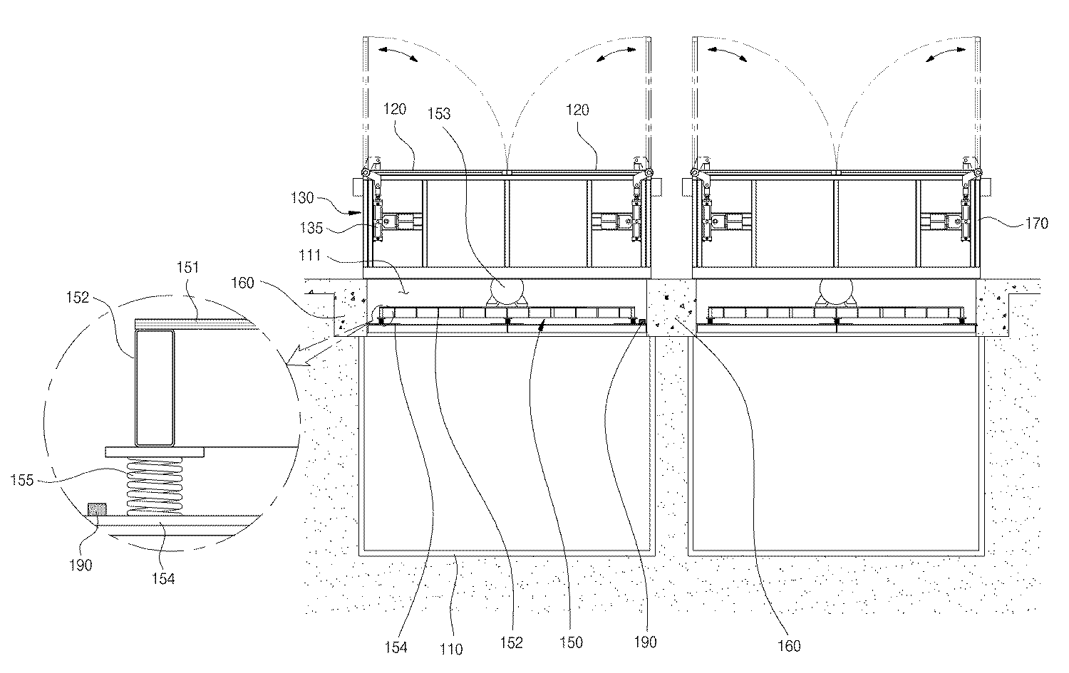
도 1은 본 발명의 일 실시 예에 따른 진동 스크린부가 구비된 슬러지 저장조 개폐장치가 설치된 상태를 나타내는 단면도이다.
도 2는 도 1의 평면도이다.
도 3은 본 발명의 일 실시 예에 따른 진동 스크린부가 구비된 슬러지 저장조 개폐장치에서 투입 도어와 도어 구동유닛의 결합관계를 나타내는 도면이다.
도 4는 도 1에서 진동 스크린부가 설치된 상태를 나타내는 평면도이다.
도 5는 본 발명의 일 실시 예에 따른 진동 스크린부가 구비된 슬러지 저장조 개폐장치의 제어관계를 나타내는 블록도이다.1 is a cross-sectional view showing a state in which a sludge storage tank opening and closing device provided with a vibrating screen unit according to an embodiment of the present invention is installed.
2 is a plan view of FIG. 1.
3 is a view showing a coupling relationship between the input door and the door driving unit in the sludge storage tank opening and closing device provided with a vibrating screen portion according to an embodiment of the present invention.
FIG. 4 is a plan view illustrating a vibrating screen unit installed in FIG. 1.
5 is a block diagram showing a control relationship of the sludge storage tank opening and closing device provided with a vibrating screen unit according to an embodiment of the present invention.
본 발명과 본 발명의 동작상의 이점 및 본 발명의 실시에 의하여 달성되는 목적을 충분히 이해하기 위해서는 본 발명의 바람직한 실시 예를 예시하는 첨부 도면 및 첨부 도면에 기재된 내용을 참조하여야만 한다.In order to fully understand the present invention, the operational advantages of the present invention, and the objects achieved by the practice of the present invention, reference should be made to the accompanying drawings which illustrate preferred embodiments of the present invention and the contents described in the accompanying drawings.
이하, 첨부된 도면을 참조하여 본 발명의 바람직한 실시 예를 설명함으로써, 본 발명을 상세히 설명한다. 각 도면에 제시된 동일한 참조부호는 동일한 부재를 나타낸다.Hereinafter, exemplary embodiments of the present invention will be described in detail with reference to the accompanying drawings. Like reference numerals in the drawings denote like elements.
도 1은 본 발명의 일 실시 예에 따른 진동 스크린부가 구비된 슬러지 저장조 개폐장치가 설치된 상태를 나타내는 단면도이고, 도 2는 도 1의 평면도이며, 도 3은 본 발명의 일 실시 예에 따른 진동 스크린부가 구비된 슬러지 저장조 개폐장치에서 투입 도어와 도어 구동유닛의 결합관계를 나타내는 도면이고, 도 4는 도 1에서 진동 스크린부가 설치된 상태를 나타내는 평면도이며, 도 5는 본 발명의 일 실시 예에 따른 진동 스크린부가 구비된 슬러지 저장조 개폐장치의 제어관계를 나타내는 블록도이다.1 is a cross-sectional view showing a state in which a sludge storage tank opening and closing device provided with a vibrating screen portion according to an embodiment of the present invention, Figure 2 is a plan view of Figure 1, Figure 3 is a vibration screen according to an embodiment of the present invention In the sludge storage tank opening and closing device provided with the addition is a view showing a coupling relationship between the input door and the door drive unit, Figure 4 is a plan view showing a state in which the vibration screen unit is installed in Figure 1, Figure 5 is a vibration according to an embodiment of the present invention It is a block diagram which shows the control relationship of the sludge storage tank switchgear provided with a screen part.
이들 도면에 도시된 바와 같이, 본 발명의 일 실시 예에 따른 진동 스크린부가 구비된 슬러지 저장조 개폐장치(이하, '개폐장치'라 한다)는, 슬러지 저장조(110)의 투입구(111)를 개폐하도록 투입 도어(120)를 작동시키는 도어 구동유닛(130)과, 투입 도어(120)의 하측에 마련되는 진동 스크린부(150)를 포함한다.As shown in these drawings, the sludge storage tank opening and closing device (hereinafter referred to as "opening and closing device") provided with a vibrating screen portion according to an embodiment of the present invention, to open and close the
먼저, 슬러지 저장조(110), 진동 스크린부(150)와 후술하는 슬러지 투입 유도몸체(170)의 설치에 대해 간략하게 설명하면, 도 1에 도시한 바와 같이, 슬러지 저장조(110)를 지중에 매립 설치하며 슬러지 저장조(110) 상측 주변 영역에 콘크리트 타설을 통해 콘크리트 벽체(160)를 설치한다. 이러한 콘크리트 벽체(160)의 상측에는 투입 도어(120)가 구비된 슬러지 투입 유도몸체(170)가 설치된다.First, the installation of the
본 실시예에 따른 개폐장치는 진동 스크린부(150)를 마련함으로써, 투입구(111)로 투입되는 슬러지에 이물질이 포함되어 있는 경우 이러한 이물질을 거를 수 있도록 함과 더불어 슬러지가 보다 용이하면서도 신속하게 슬러지 저장조(110) 내부 공간으로 낙하하여 수용되도록 할 뿐만 아니라, 슬러지 입자들이 서로 엉켜서 고착되는 것을 방지할 수 있다. 덧붙여, 진동 스크린부(150)가 슬러지에 포함된 이물질을 거름으로써 이물질에 의해 슬러지 저장조(110) 및 기타 주변 구성품의 파손을 방지할 수 있다. 또한, 진동 스크린부(150)를 구비함으로 인해 투입 도어(120)의 개방시에 작업자가 부주의로 인해 슬러지 저장조(110) 내부로 낙하하는 것을 방지하여 안전사고 발생을 방지할 수 있게 된다.Opening and closing device according to the present embodiment by providing a vibrating
도 1 및 도 2에 도시한 바와 같이, 투입 도어(120)는 진동 스크린부(150)의 상측에 배치된 슬러지 투입 유도몸체(170)에 대해 회전 가능하게 설치된 회전축(121)을 구비한다.As shown in FIG. 1 and FIG. 2, the
본 실시예에서, 도 2에 도시한 바와 같이, 투입 도어(120)는, 하나의 슬러지 저장조(110)의 투입구(111)를 개방 또는 폐쇄하도록 한 쌍으로 설치되며, 한 쌍의 투입 도어(120)는 슬러지 투입 유도몸체(170)에 베어링 등을 통해 회전 가능하게 설치된 회전축(121)을 통해 각각 회전 가능하게 된다. 그러나, 반드시 이에 한정되는 것은 아니며 하나의 투입구(111)를 개방 또는 폐쇄하도록 하나의 투입 도어(120)가 설치되어도 무방하다.In this embodiment, as shown in Figure 2, the
도 1 및 도 2에 도시한 바와 같이, 도어 구동유닛(130)은 슬러지 저장조(110)의 투입구(111)를 개폐하도록 투입 도어(120)를 작동(회전)시키는 것으로서, 투입 도어(120)를 자동으로 회전하기 위한 도어 자동구동유닛(131)과 투입 도어(120)를 작업자가 수동으로 회전하기 위한 도어 수동구동유닛(132)을 포함한다.As shown in FIGS. 1 and 2, the
먼저, 도어 수동구동유닛(132)은, 투입 도어(120)의 회전축(121)에 연결되는 수동핸들바(132)로 구성된다. 따라서, 작업자는 수동핸들바(132)를 회전시켜 투입 도어(120)를 회전할 수 있다.First, the door
다음, 도어 자동구동유닛(131)은, 투입 도어(120)의 회전축(121)에 연결되는 아암부(133)와, 아암부(133)의 단부에 실린더 로드(136)가 연결되도록 설치되는 실린더부(135)를 포함한다.Next, the door
본 실시예에서, 도 2에 도시한 바와 같이, 실린더부(135)는 회전축(121)의 일단에 연결되도록 설치되어 있지만, 반드시 이에 한정되는 것은 아니며, 실린더부(135)는 회전축(121)의 양단에 각각 연결되도록 복수로 설치될 수도 있다. 이하에서는 도면에 도시한 바와 같이 실린더부(135)가 1개로 마련되어 회전축(121)의 일단에 연결되도록 설치되는 것을 기준으로 설명한다. In the present embodiment, as shown in Figure 2, the
아암부(133)는, 대략 'ㄱ'자 형상으로 절곡 형성되고 회전축(121)의 일단에 연결되어 실린더부(135)의 작동에 따라 회전축(121)의 길이 방향 축선과 동일한 가상의 힌지축을 중심으로 회전하며, 아암부(133)가 회전함에 따라 투입 도어(120) 또한 회전하여 투입구(111)를 개방 또는 폐쇄하게 된다. 즉, 아암부(133)와 회전축(121)은 실린더부(135)의 작동에 따라 실질적으로 동시에 회전이 이루어진다. The
정리하자면, 실린더부(135)의 작동에 의해 아암부(133) 및 회전축(121)은 회전하게 되고, 회전축(121)의 회전에 따라 회전축(121)과 일체로 연결되는 투입 도어(120) 또한 회전하여 투입구(111)를 개방 또는 폐쇄하게 된다.In summary, the
한편, 아암부(133)와 회전축(121) 사이의 결합력을 보다 상승시키도록, 즉 아암부(133)와 회전축(121)의 상호 접촉부위의 결합력을 높여 상기 상호 접촉부위에서 미끄럼이 발생하여 회전축(121)이 회전하지 못하는 현상이 발생하는 것을 방지하는 것이 보다 바람직하다. 이를 위해, 도 3에 도시한 바와 같이, 본 실시예에서는, 회전축(121)에 키홈(122)을 형성하고 아암부(133), 구체적으로 아암부(133)의 내주면에는 키홈(122)과 대응하도록 돌출키(134)를 형성할 수 있다. 물론, 이와 반대로 회전축(121)에 돌출키를 형성하고 아암부(133)에는 돌출키와 대응하도록 키홈을 형성할 수도 있다.On the other hand, to increase the coupling force between the
도 3에 도시한 바와 같이, 본 실시예에 따른 개폐장치는, 투입 도어(120)의 회전각도를 제한하는 도어 회전제한부(138)를 더 포함한다.As shown in FIG. 3, the opening and closing apparatus according to the present embodiment further includes a door
한편, 투입 도어(120)는 상측 방향으로 회전하여 투입구(111)를 개방시키게 되고, 그 반대인 하측 방향으로 회전하여 투입구(111)를 폐쇄하게 된다. 도어 회전제한부(138)는 이러한 투입 도어(120)의 상측 또는 하측 방향 회전을 제한하여 투입 도어(120)가 필요 이상으로 회전하는 것을 방지한다.On the other hand, the
도 3에 도시한 바와 같이, 도어 회전제한부(138)는, 회전축(121)의 외주면에 돌출 형성되는 스토퍼(139)와, 회전축(121)과 이격되게 설치되어 스토퍼(139)와의 접촉을 통해 투입 도어(120)의 상하방향 회전을 감지하는 리미트 스위치부(142)를 포함한다.As shown in FIG. 3, the door
리미트 스위치부(142)는 기계적인 접촉에 의해 회전축(121)의 회전을 감지하는 것으로서, 투입 도어(120)의 하측 방향 회전을 감지하는 상측 회전감지부(143)와, 상측 회전감지부(143)의 하측에 설치되어 투입 도어(120)의 상측 방향 회전을 감지하는 하측 회전감지부(144)를 포함한다.The
여기서, 상측 회전감지부(143)와 하측 회전감지부(144)는 각각, 회전감지부 몸체(145)와, 회전감지부 몸체(145)에 설치되되 스토퍼(139)와의 접촉시에 회전 가능하도록 설치되는 접촉감지편(146)을 포함한다. 회전감지부 몸체(145)는 슬러지 투입 유도몸체(170)에 연결된 별도의 브래킷(171)에 설치될 수 있다.Here, the upper
즉, 상측 회전감지부(143)의 접촉감지편(146)은, 투입구(111)를 폐쇄시키고자 투입 도어(120)를 하측 방향으로 회전할 때 스토퍼(139)에 접촉하여 투입 도어(120)가 필요 이상으로 하측 방향으로 회전하는 것을 방지한다. 마찬가지로, 하측 회전감지부(144)의 접촉감지편(146)은 투입 도어(120)가 필요 이상으로 상측 방향으로 회전하는 것을 방지한다. 아래에서 다시 설명하겠지만, 후술하는 제어부(180)는 리미트 스위치부(142)의 감지신호를 전달받아 스토퍼(139)가 접촉감지편(146)에 접촉하는 것으로 감지되면 실린더부(135)의 작동을 정지시킨다. That is, the
도 1 및 도 4에 도시한 바와 같이, 진동 스크린부(150)는 투입 도어(120)의 하측에 마련되어 슬러지에 포함된 이물질을 거르거나 슬러지가 보다 신속하게 슬러지 저장조(110) 내부로 낙하하여 수용되도록 하는 것으로서, 진동 스크린(151)과, 진동 스크린(151)을 지지하는 지지 프레임(152)과, 진동 스크린(151)에 진동을 부여하는 진동모터(153)를 포함한다.1 and 4, the vibrating
진동 스크린(151)은 직경 2.5~3.5mm의 금속 와이어를 포함하는 복수의 격자망으로 구성되며, 본 실시예에서 격자망을 구성하는 망목의 크기는 30mm×60mm 또는 60mm×60mm로 적용된다. 이에 따라, 전술한 망목의 크기보다 작은 슬러지 입자는 진동 스크린(151)을 통과한 후 슬러지 저장조(110)로 수용되지만 망목보다 큰 슬러지 입자 및/또는 이물질 등은 진동 스크린(151)에 걸리게 되며, 작업자는 진동 스크린(151)에 걸린 슬러지 입자 및/또는 이물질을 수거하여 후처리 작업하거나 폐기처리 할 수 있다. 이러한 진동 스크린(151)은 스테인레스 계열의 소재로 이루어질 수 있으며 지지 프레임(152)에 용접 등을 통해 고정 설치될 수 있다.Vibrating
지지 프레임(152)은 진동 스크린(151)의 하측에 배치되어 진동 스크린(151)을 지지한다. 이러한 지지 프레임(152)은 복수의 가로 프레임과 세로 프레임이 상호 간에 용접을 통해 일체화되어 제작된다.The
도 1 및 도 4에 도시한 바와 같이, 진동모터(153)는 진동 스크린(151)의 상측에 배치되며, 후술하는 제어부(180)의 작동 신호 전달에 의해 동작이 ON/OFF된다. 이러한 진동모터(153)는 하나 또는 서로 이격되게 복수로 설치될 수 있으며, 본 실시예에서 진동모터(153)는 정격 2.2KW 용량으로 적용되지만 이에 한정되지 않으며 진동 스크린(151)의 면적 및 전술한 금속 와이어의 두께에 따라 충분히 조절될 수 있다.1 and 4, the
도 1에 도시한 바와 같이, 진동 스크린부(150)는, 지지 프레임(152)의 측 방향에 마련된 콘크리트 벽체(160)에 마운팅되어 지지 프레임(152)을 지지하는 지지 브래킷(154)과, 지지 브래킷(154)과 지지 프레임(152) 사이에 마련되는 댐퍼(155)를 더 포함한다.As shown in FIG. 1, the
이러한 지지 브래킷(154)과 댐퍼(155)는 진동모터(153)로부터 발생된 진동이 콘크리트 벽체(160) 및 슬러지 저장조(110)에 전달되는 것을 보다 최소화하도록 진동을 저감시키는 것이다. 본 실시예에서, 지지 브래킷(154)은 콘크리트 벽체(160)에 케미컬 앙카(미도시) 등을 통해 고정 설치될 수 있다.The
한편, 댐퍼(155)는, 진동모터(153)에서 발생된 진동을 흡수하여 이러한 진동이 콘크리트 벽체(160) 및 슬러지 저장조(110)로 전달되는 정도를 실질적으로 최소화하는 것으로서, 스프링(155) 또는 고무(미도시)로 적용될 수 있다. 도 1에서는 편의상 댐퍼(155)가 스프링(155)으로 도시되는 것을 기준으로 도시한다.Meanwhile, the
본 실시예에서, 진동 스크린(151), 지지 프레임(152) 및 지지 브래킷(154)은 슬러지에 포함된 수분에 의해 부식되는 것을 방지하도록 스테인레스 계열의 소재로 이루어지는 것이 바람직하다.In the present embodiment, the
도 5에 도시한 바와 같이, 본 실시예에 따른 개폐장치는, 진동모터(153) 및 실린더부(135)의 작동을 제어하는 제어부(180)를 더 포함한다.As shown in FIG. 5, the opening and closing apparatus according to the present embodiment further includes a
일 예로, 제어부(180)는, 외부로부터 인가되는 동작 신호에 따라 실린더부(135)를 작동하며, 이후 리미트 스위치부(142)의 감지신호를 전달받아 스토퍼(139)가 접촉감지편(146)에 접촉하는 것으로 감지되면 실린더부(135)의 작동을 정지시키며, 실린더부(135)가 작동 정지하고 일정 시간이 경과하면 진동모터(153)에 신호를 전달하여 진동모터(153)를 작동하거나 작동 중인 진동모터(153)를 작동 정지한다.For example, the
보다 구체적으로, 투입구(111)를 개방하고자 투입 도어(120)를 상측 방향으로 회전할 경우, 즉 실린더부(135)의 실린더 로드(136)의 단부를 일정 이상 상측으로 이동하는 경우에 회전축(121)에 형성된 스토퍼(139)는 하측 회전감지부(144)의 접촉감지편(146)에 접촉된다. 이러한 경우, 제어부(180)는 투입 도어(120)가 더 이상 상측 방향으로 회전하는 것을 정지하고 타임 제어방법을 이용하여 일정 시간이 경과되면 진동모터(153)에 동작신호를 전달하여 진동모터(153)가 작동하도록 한다.More specifically, the
반대로, 투입구(111)를 폐쇄시키고자 투입 도어(120)를 하측 방향으로 회전하는 경우, 즉 실린더부(135)의 실린더 로드(136)의 단부를 일정 이상 하측으로 이동하는 경우에 회전축(121)에 형성된 스토퍼(139)는 상측 회전감지부(143)의 접촉감지편(146)에 접촉된다. 이러한 경우, 제어부(180)는 투입 도어(120)가 더 이상 하측 방향으로 회전하는 것을 정지할 뿐만 아니라 진동모터(153)로의 전원 인가를 OFF한다. On the contrary, when the
전술한 제어부(180)의 제어는 타임 제어를 이용한 방법으로서, 투입 도어(120)가 일정 각도 회전하고 일정 시간이 경과되면 진동모터(153)를 작동하거나 그 작동을 정지하는 것이다. The control of the
이하에서는 이러한 타임 제어가 아닌 감지센서를 통해 슬러지가 투입되는지의 여부를 감지한 후 제어부(180)가 진동모터(153)의 작동을 제어하는 것에 대해 설명한다.Hereinafter, the
도 1에 도시한 바와 같이, 진동 스크린부(150)는, 투입 도어(120)의 개방 여부를 감지하는 감지센서(190)를 더 포함한다. 이러한 감지센서(190)는 광센서 또는 적외선 센서로 적용이 가능하며, 콘크리트 벽체(160) 또는 지지 브래킷(154)에 설치될 수 있다.As shown in FIG. 1, the
광센서는 빛을 감지하는 센서로서 감지센서(190)가 광센서로 적용되는 경우, 감지센서(190)는 외부로부터 슬러지 투입 유도몸체(170)의 내측으로 유입되는 빛을 감지하여 투입 도어(120)의 개방 여부를 감지하게 된다.When the optical sensor is a sensor for detecting light and the
적외선 센서는 대상체와의 거리, 설정된 영역 내에 물체 등이 존재하는 가의 여부 등을 감지하는 센서로서 감지센서(190)가 적외선 센서로 적용되는 경우, 감지센서(190)는 슬러지가 투입구(111)로 투입되는가의 여부를 감지한다. 여기서, 적외선 센서는 발광부와 수광부가 분리된 구조 또는 발광부와 수광부가 일체로 된 구조로 적용될 수 있다.Infrared sensor is a sensor for detecting the distance to the object, whether or not the object exists in the set area, etc. When the
정리하자면, 제어부(180)는, 광센서 또는 적외선 센서를 통해 투입 도어(120)가 개방되거나 실질적으로 슬러지가 투입되는 것으로 감지되면 진동모터(153)를 작동한다.In summary, the
본 실시예 및 본 명세서에 첨부된 도면은 본 발명에 포함되는 기술적 사상의 일부를 명확하게 나타내고 있는 것에 불과하며, 본 발명의 명세서 및 도면에 포함된 기술적 사상의 범위 내에서 당업자가 용이하게 유추할 수 있는 변형 예와 구체적인 실시 예는 모두 본 발명의 권리범위에 포함되는 것이 자명하다고 할 것이다.The embodiments and drawings attached to this specification are merely to clearly show some of the technical ideas included in the present invention, and those skilled in the art can easily infer within the scope of the technical ideas included in the specification and drawings of the present invention. Modifications that can be made and specific embodiments will be apparent that both are included in the scope of the invention.
110: 슬러지 저장조 120: 투입 도어
122: 키홈 130: 도어 구동유닛
131: 도어 자동구동유닛 132: 도어 수동구동유닛
133: 아암부 134: 돌출키
135: 실린더부 138: 도어 회전제한부
139: 스토퍼 142: 리미트 스위치부
146: 접촉감지편 150: 진동 스크린부
151: 진동 스크린 152: 지지 프레임
153: 진동모터 154: 지지 브래킷
155: 댐퍼 160: 콘크리트 벽체
180: 제어부 190: 감지센서110: sludge reservoir 120: input door
122: keyway 130: door drive unit
131: door automatic drive unit 132: door manual drive unit
133: arm portion 134: protruding key
135: cylinder portion 138: door rotation limiting portion
139: stopper 142: limit switch
146: contact detection piece 150: vibration screen portion
151: vibrating screen 152: support frame
153: vibration motor 154: support bracket
155: damper 160: concrete wall
180: control unit 190: detection sensor
Claims (12)
상기 투입 도어의 하측에 마련되는 진동 스크린부를 포함하되,
상기 진동 스크린부는,
진동 스크린;
상기 진동 스크린을 지지하는 지지 프레임;
상기 진동 스크린에 진동을 부여하는 진동모터;
상기 지지 프레임의 측방향에 마련된 콘크리트 벽체에 마운팅되어 상기 지지 프레임을 지지하는 지지 브래킷; 및
상기 지지 브래킷과 상기 지지 프레임 사이에 마련되는 댐퍼를 포함하는 것을 특징으로 하는 진동 스크린부가 구비된 슬러지 저장조 개폐장치.A door driving unit for operating the input door to open and close the inlet of the sludge storage tank; And
Including a vibrating screen portion provided on the lower side of the input door,
The vibrating screen unit,
Vibrating screen;
A support frame for supporting the vibrating screen;
A vibration motor for imparting vibration to the vibration screen;
A support bracket mounted to a concrete wall provided in a lateral direction of the support frame to support the support frame; And
Sludge reservoir opening and closing device provided with a vibrating screen portion, characterized in that it comprises a damper provided between the support bracket and the support frame.
상기 댐퍼는 스프링 또는 고무인 것을 특징으로 하는 진동 스크린부가 구비된 슬러지 저장조 개폐장치.The method of claim 1,
The damper is a sludge storage tank opening and closing device having a vibrating screen portion, characterized in that the spring or rubber.
상기 진동 스크린, 상기 지지 프레임 및 상기 지지 브래킷은 스테인레스 계열의 소재로 이루어지고,
상기 진동 스크린은 복수의 격자망으로 구성되되, 상기 격자망을 구성하는 망목의 크기는 30mm×60mm 또는 60mm×60mm이며, 상기 진동 스크린은 상기 지지 프레임에 용접되는 것을 특징으로 하는 진동 스크린부가 구비된 슬러지 저장조 개폐장치.The method of claim 1,
The vibration screen, the support frame and the support bracket is made of a stainless material,
The vibrating screen is composed of a plurality of grid, the size of the mesh constituting the grid is 30mm × 60mm or 60mm × 60mm, the vibrating screen is provided with a vibrating screen, characterized in that welded to the support frame Sludge reservoir opening.
상기 투입 도어는 상기 진동 스크린부의 상측에 배치된 슬러지 투입 유도몸체에 대해 회전 가능하게 설치된 회전축을 구비하며,
상기 도어 구동유닛은, 상기 투입 도어를 자동으로 회전하기 위한 도어 자동구동유닛과 상기 투입 도어를 수동으로 회전하기 위한 도어 수동구동유닛을 포함하는 것을 특징으로 하는 진동 스크린부가 구비된 슬러지 저장조 개폐장치.The method of claim 1,
The input door has a rotating shaft rotatably installed with respect to the sludge input guide body disposed on the upper side of the vibrating screen,
The door driving unit, a sludge storage tank opening and closing device having a vibrating screen portion, characterized in that it comprises a door automatic driving unit for automatically rotating the closing door and the door manual driving unit for manually rotating the closing door.
상기 도어 자동구동유닛은,
상기 투입 도어의 회전축에 연결되는 아암부; 및
상기 아암부의 단부에 실린더 로드가 연결되도록 설치되는 실린더부를 포함하며,
상기 실린더부의 작동에 의해 상기 아암부 및 상기 투입 도어는 회전하는 것을 특징으로 하는 진동 스크린부가 구비된 슬러지 저장조 개폐장치.The method of claim 5,
The door automatic drive unit,
An arm part connected to the rotation shaft of the input door; And
A cylinder portion installed to connect a cylinder rod to an end of the arm portion,
And the arm part and the input door rotate by the operation of the cylinder part.
상기 도어 수동구동유닛은, 상기 투입 도어의 회전축에 연결되는 수동핸들바를 포함하는 것을 특징으로 하는 진동 스크린부가 구비된 슬러지 저장조 개폐장치.The method of claim 5,
The door manual drive unit, the sludge storage tank opening and closing device provided with a vibrating screen portion, characterized in that it comprises a manual handle bar connected to the rotation axis of the input door.
상기 투입 도어의 회전각도를 제한하는 도어 회전제한부를 더 포함하되,
상기 도어 회전제한부는,
상기 회전축의 외주면에 돌출 형성되는 스토퍼; 및
상기 회전축과 이격되게 설치되어 상기 스토퍼와의 접촉을 통해 상기 투입 도어의 회전을 감지하는 리미트 스위치부를 포함하는 것을 특징으로 하는 진동 스크린부가 구비된 슬러지 저장조 개폐장치.The method of claim 6,
Further comprising a door rotation limit to limit the rotation angle of the input door,
The door rotation limit unit,
A stopper protruding from an outer circumferential surface of the rotating shaft; And
Sludge storage tank opening and closing device provided with a vibrating screen portion is provided to be spaced apart from the rotating shaft and includes a limit switch unit for detecting the rotation of the input door through contact with the stopper.
상기 리미트 스위치부는,
상기 투입 도어의 하측 방향 회전을 감지하는 상측 회전감지부; 및
상기 상측 회전감지부의 하측에 설치되어 상기 투입 도어의 상측 방향 회전을 감지하는 하측 회전감지부를 포함하되,
상기 상측 회전감지부와 상기 하측 회전감지부는 각각,
회전감지부 몸체; 및
상기 회전감지부 몸체에 설치되되 상기 스토퍼와의 접촉시에 회전 가능하도록 설치되는 접촉감지편을 포함하는 것을 특징으로 하는 진동 스크린부가 구비된 슬러지 저장조 개폐장치.The method of claim 8,
The limit switch unit,
An upper rotation detecting unit detecting a lower direction rotation of the input door; And
It is installed on the lower side of the upper rotation detecting unit includes a lower rotation detecting unit for detecting the upper direction rotation of the input door,
The upper rotation detection unit and the lower rotation detection unit, respectively
Rotation sensing unit body; And
Sludge storage tank opening and closing device having a vibrating screen unit is installed on the rotation sensing unit body and comprises a contact sensing piece that is installed to be rotatable upon contact with the stopper.
상기 진동모터 및 상기 실린더부의 작동을 제어하는 제어부를 더 포함하며,
상기 제어부는, 외부로부터 인가되는 동작 신호에 따라 상기 실린더부를 작동하며, 이후 상기 리미트 스위치부의 감지신호를 전달받아 스토퍼가 접촉감지편에 접촉하는 것으로 감지되면 상기 실린더부의 작동을 정지하며, 상기 실린더부가 작동 정지하고 일정 시간이 경과하면 상기 진동 모터를 작동하거나 작동 중인 진동 모터를 작동 정지하는 것을 특징으로 하는 진동 스크린부가 구비된 슬러지 저장조 개폐장치.10. The method of claim 9,
Further comprising a control unit for controlling the operation of the vibration motor and the cylinder portion,
The control unit operates the cylinder unit according to an operation signal applied from the outside, and after receiving the detection signal of the limit switch unit, stops the operation of the cylinder unit when it is detected that the stopper contacts the contact sensing piece, and the cylinder unit Sludge storage tank opening and closing device having a vibration screen unit, characterized in that for operating the vibration motor or stop operating the vibration motor when a certain time elapses after the operation stops.
상기 진동모터 및 상기 실린더부의 작동을 제어하는 제어부를 더 포함하며,
상기 진동 스크린부는, 상기 투입 도어의 개방 여부를 감지하는 감지센서를 더 포함하며,
상기 제어부는, 상기 감지센서의 감지 신호를 전달받아 상기 투입 도어가 개방된 것으로 감지되면 상기 진동모터를 작동하는 것을 특징으로 하는 진동 스크린부가 구비된 슬러지 저장조 개폐장치.The method of claim 6,
Further comprising a control unit for controlling the operation of the vibration motor and the cylinder portion,
The vibrating screen unit further includes a detection sensor for detecting whether the input door is opened,
The control unit, the sludge storage tank opening and closing device having a vibrating screen unit, characterized in that for operating the vibration motor when it is detected that the input door is opened by receiving the detection signal of the sensor.
상기 감지센서는 광센서 또는 적외선 센서인 것을 특징으로 하는 진동 스크린부가 구비된 슬러지 저장조 개폐장치.The method of claim 11,
The detection sensor is a sludge storage tank opening and closing device having a vibrating screen portion, characterized in that an optical sensor or an infrared sensor.
Priority Applications (1)
| Application Number | Priority Date | Filing Date | Title |
|---|---|---|---|
| KR1020100103790A KR101070478B1 (en) | 2010-10-25 | 2010-10-25 | Sludge reservoir opening and closing device with vibrating screen |
Applications Claiming Priority (1)
| Application Number | Priority Date | Filing Date | Title |
|---|---|---|---|
| KR1020100103790A KR101070478B1 (en) | 2010-10-25 | 2010-10-25 | Sludge reservoir opening and closing device with vibrating screen |
Publications (1)
| Publication Number | Publication Date |
|---|---|
| KR101070478B1 true KR101070478B1 (en) | 2011-10-06 |
Family
ID=45032369
Family Applications (1)
| Application Number | Title | Priority Date | Filing Date |
|---|---|---|---|
| KR1020100103790A Active KR101070478B1 (en) | 2010-10-25 | 2010-10-25 | Sludge reservoir opening and closing device with vibrating screen |
Country Status (1)
| Country | Link |
|---|---|
| KR (1) | KR101070478B1 (en) |
Cited By (3)
| Publication number | Priority date | Publication date | Assignee | Title |
|---|---|---|---|---|
| KR101545681B1 (en) * | 2015-03-16 | 2015-08-20 | 동 석 강 | Screen apparatus for an overall wastes processing equipment with high efficient vibratory dehydration |
| KR101549872B1 (en) | 2015-03-27 | 2015-09-04 | 신진유지건설 주식회사 | Drain water discharged from food processing system processes |
| CN116835737A (en) * | 2023-08-10 | 2023-10-03 | 遂宁碳基环保科技有限公司 | Automatic purification system and method for farmland sewage |
Citations (3)
| Publication number | Priority date | Publication date | Assignee | Title |
|---|---|---|---|---|
| KR200204255Y1 (en) * | 2000-06-16 | 2000-11-15 | 이화자 | Door structure of sludge storage tank |
| JP2005088633A (en) | 2003-09-12 | 2005-04-07 | Morita Corp | Rear door lock device for suction vehicle tank |
| KR100905124B1 (en) | 2007-10-04 | 2009-06-30 | 주식회사 포스코 | Wastewater and Sludge Treatment System |
-
2010
- 2010-10-25 KR KR1020100103790A patent/KR101070478B1/en active Active
Patent Citations (3)
| Publication number | Priority date | Publication date | Assignee | Title |
|---|---|---|---|---|
| KR200204255Y1 (en) * | 2000-06-16 | 2000-11-15 | 이화자 | Door structure of sludge storage tank |
| JP2005088633A (en) | 2003-09-12 | 2005-04-07 | Morita Corp | Rear door lock device for suction vehicle tank |
| KR100905124B1 (en) | 2007-10-04 | 2009-06-30 | 주식회사 포스코 | Wastewater and Sludge Treatment System |
Cited By (4)
| Publication number | Priority date | Publication date | Assignee | Title |
|---|---|---|---|---|
| KR101545681B1 (en) * | 2015-03-16 | 2015-08-20 | 동 석 강 | Screen apparatus for an overall wastes processing equipment with high efficient vibratory dehydration |
| KR101549872B1 (en) | 2015-03-27 | 2015-09-04 | 신진유지건설 주식회사 | Drain water discharged from food processing system processes |
| CN116835737A (en) * | 2023-08-10 | 2023-10-03 | 遂宁碳基环保科技有限公司 | Automatic purification system and method for farmland sewage |
| CN116835737B (en) * | 2023-08-10 | 2024-02-20 | 遂宁碳基环保科技有限公司 | Automatic purification system and method for farmland sewage |
Similar Documents
| Publication | Publication Date | Title |
|---|---|---|
| KR101770412B1 (en) | Water tank for wastewater disposal | |
| KR100947312B1 (en) | Pick-up device to charge the taxes at a food garbage | |
| CN209178224U (en) | A kind of sewage sludge dehydration treatment equipment | |
| KR20150065413A (en) | Units for automatic measuring quality of water | |
| US5582720A (en) | Drain closure apparatus | |
| KR101908799B1 (en) | Toilet for pets | |
| KR20140013491A (en) | Two-stage separator | |
| KR101132845B1 (en) | Opening and shutting apparatus of manhole cover | |
| CN105600220B (en) | A kind of minitype waste processing equipment | |
| CN207144001U (en) | A kind of inspection shaft easy to clean | |
| WO2020141529A1 (en) | Fluid monitoring system and support arrangement thereof | |
| KR101739644B1 (en) | Toilet for pets | |
| CN105501760A (en) | Mini-sized garbage treatment equipment | |
| CN108264187B (en) | Energy-concerving and environment-protective water pollution solid waste handles and utilizes equipment | |
| KR100865582B1 (en) | Garbage compressor | |
| KR102149596B1 (en) | Monitoring and control system of sewage facilities using multi path communication devices | |
| KR20200014958A (en) | Apparatus for removing residual substances in a concrete pump car | |
| KR102303905B1 (en) | Rainwater collecting apparatus with initial rainwater exclusion device using IoT | |
| CN112354243A (en) | Pipeline filtering system | |
| CN105668072B (en) | A kind of minitype waste processing equipment | |
| JP4163092B2 (en) | Drum screen operation detection system in overflow water dust removal equipment | |
| KR101330304B1 (en) | Resin sampling device and method for high-pressure boiler tank | |
| KR101471658B1 (en) | Open and close apparatus | |
| CN214130544U (en) | A pipeline filter system | |
| KR101667491B1 (en) | A apparatus for water treatment |
Legal Events
| Date | Code | Title | Description |
|---|---|---|---|
| A201 | Request for examination | ||
| PA0109 | Patent application |
St.27 status event code: A-0-1-A10-A12-nap-PA0109 |
|
| PA0201 | Request for examination |
St.27 status event code: A-1-2-D10-D11-exm-PA0201 |
|
| A302 | Request for accelerated examination | ||
| PA0302 | Request for accelerated examination |
St.27 status event code: A-1-2-D10-D17-exm-PA0302 St.27 status event code: A-1-2-D10-D16-exm-PA0302 |
|
| D13-X000 | Search requested |
St.27 status event code: A-1-2-D10-D13-srh-X000 |
|
| D14-X000 | Search report completed |
St.27 status event code: A-1-2-D10-D14-srh-X000 |
|
| E902 | Notification of reason for refusal | ||
| PE0902 | Notice of grounds for rejection |
St.27 status event code: A-1-2-D10-D21-exm-PE0902 |
|
| E13-X000 | Pre-grant limitation requested |
St.27 status event code: A-2-3-E10-E13-lim-X000 |
|
| P11-X000 | Amendment of application requested |
St.27 status event code: A-2-2-P10-P11-nap-X000 |
|
| P13-X000 | Application amended |
St.27 status event code: A-2-2-P10-P13-nap-X000 |
|
| E90F | Notification of reason for final refusal | ||
| PE0902 | Notice of grounds for rejection |
St.27 status event code: A-1-2-D10-D21-exm-PE0902 |
|
| P11-X000 | Amendment of application requested |
St.27 status event code: A-2-2-P10-P11-nap-X000 |
|
| P13-X000 | Application amended |
St.27 status event code: A-2-2-P10-P13-nap-X000 |
|
| E701 | Decision to grant or registration of patent right | ||
| PE0701 | Decision of registration |
St.27 status event code: A-1-2-D10-D22-exm-PE0701 |
|
| GRNT | Written decision to grant | ||
| PR0701 | Registration of establishment |
St.27 status event code: A-2-4-F10-F11-exm-PR0701 |
|
| PR1002 | Payment of registration fee |
St.27 status event code: A-2-2-U10-U11-oth-PR1002 Fee payment year number: 1 |
|
| PG1601 | Publication of registration |
St.27 status event code: A-4-4-Q10-Q13-nap-PG1601 |
|
| PN2301 | Change of applicant |
St.27 status event code: A-5-5-R10-R13-asn-PN2301 St.27 status event code: A-5-5-R10-R11-asn-PN2301 |
|
| R18-X000 | Changes to party contact information recorded |
St.27 status event code: A-5-5-R10-R18-oth-X000 |
|
| R18-X000 | Changes to party contact information recorded |
St.27 status event code: A-5-5-R10-R18-oth-X000 |
|
| FPAY | Annual fee payment |
Payment date: 20140929 Year of fee payment: 4 |
|
| PR1001 | Payment of annual fee |
St.27 status event code: A-4-4-U10-U11-oth-PR1001 Fee payment year number: 4 |
|
| FPAY | Annual fee payment |
Payment date: 20150923 Year of fee payment: 5 |
|
| PR1001 | Payment of annual fee |
St.27 status event code: A-4-4-U10-U11-oth-PR1001 Fee payment year number: 5 |
|
| R18-X000 | Changes to party contact information recorded |
St.27 status event code: A-5-5-R10-R18-oth-X000 |
|
| P22-X000 | Classification modified |
St.27 status event code: A-4-4-P10-P22-nap-X000 |
|
| FPAY | Annual fee payment |
Payment date: 20160928 Year of fee payment: 6 |
|
| PR1001 | Payment of annual fee |
St.27 status event code: A-4-4-U10-U11-oth-PR1001 Fee payment year number: 6 |
|
| PR1001 | Payment of annual fee |
St.27 status event code: A-4-4-U10-U11-oth-PR1001 Fee payment year number: 7 |
|
| P22-X000 | Classification modified |
St.27 status event code: A-4-4-P10-P22-nap-X000 |
|
| FPAY | Annual fee payment |
Payment date: 20180927 Year of fee payment: 8 |
|
| PR1001 | Payment of annual fee |
St.27 status event code: A-4-4-U10-U11-oth-PR1001 Fee payment year number: 8 |
|
| R18-X000 | Changes to party contact information recorded |
St.27 status event code: A-5-5-R10-R18-oth-X000 |
|
| FPAY | Annual fee payment |
Payment date: 20191031 Year of fee payment: 9 |
|
| PR1001 | Payment of annual fee |
St.27 status event code: A-4-4-U10-U11-oth-PR1001 Fee payment year number: 9 |
|
| PR1001 | Payment of annual fee |
St.27 status event code: A-4-4-U10-U11-oth-PR1001 Fee payment year number: 10 |
|
| R18-X000 | Changes to party contact information recorded |
St.27 status event code: A-5-5-R10-R18-oth-X000 |
|
| P22-X000 | Classification modified |
St.27 status event code: A-4-4-P10-P22-nap-X000 |
|
| PR1001 | Payment of annual fee |
St.27 status event code: A-4-4-U10-U11-oth-PR1001 Fee payment year number: 11 |
|
| PR1001 | Payment of annual fee |
St.27 status event code: A-4-4-U10-U11-oth-PR1001 Fee payment year number: 12 |
|
| PR1001 | Payment of annual fee |
St.27 status event code: A-4-4-U10-U11-oth-PR1001 Fee payment year number: 13 |
|
| PR1001 | Payment of annual fee |
St.27 status event code: A-4-4-U10-U11-oth-PR1001 Fee payment year number: 14 |
|
| PR1001 | Payment of annual fee |
St.27 status event code: A-4-4-U10-U11-oth-PR1001 Fee payment year number: 15 |
|
| U11 | Full renewal or maintenance fee paid |
Free format text: ST27 STATUS EVENT CODE: A-4-4-U10-U11-OTH-PR1001 (AS PROVIDED BY THE NATIONAL OFFICE) Year of fee payment: 15 |