KR100972749B1 - Paper conveying apparatus, image forming apparatus and ink-jet recording apparatus - Google Patents
Paper conveying apparatus, image forming apparatus and ink-jet recording apparatus Download PDFInfo
- Publication number
- KR100972749B1 KR100972749B1 KR1020087002008A KR20087002008A KR100972749B1 KR 100972749 B1 KR100972749 B1 KR 100972749B1 KR 1020087002008 A KR1020087002008 A KR 1020087002008A KR 20087002008 A KR20087002008 A KR 20087002008A KR 100972749 B1 KR100972749 B1 KR 100972749B1
- Authority
- KR
- South Korea
- Prior art keywords
- paper
- pressing member
- pressing
- paper pressing
- members
- Prior art date
Links
Images


Classifications
-
- B—PERFORMING OPERATIONS; TRANSPORTING
- B41—PRINTING; LINING MACHINES; TYPEWRITERS; STAMPS
- B41J—TYPEWRITERS; SELECTIVE PRINTING MECHANISMS, i.e. MECHANISMS PRINTING OTHERWISE THAN FROM A FORME; CORRECTION OF TYPOGRAPHICAL ERRORS
- B41J11/00—Devices or arrangements of selective printing mechanisms, e.g. ink-jet printers or thermal printers, for supporting or handling copy material in sheet or web form
- B41J11/02—Platens
-
- B—PERFORMING OPERATIONS; TRANSPORTING
- B65—CONVEYING; PACKING; STORING; HANDLING THIN OR FILAMENTARY MATERIAL
- B65H—HANDLING THIN OR FILAMENTARY MATERIAL, e.g. SHEETS, WEBS, CABLES
- B65H5/00—Feeding articles separated from piles; Feeding articles to machines
- B65H5/36—Article guides or smoothers, e.g. movable in operation
- B65H5/38—Article guides or smoothers, e.g. movable in operation immovable in operation
-
- B—PERFORMING OPERATIONS; TRANSPORTING
- B41—PRINTING; LINING MACHINES; TYPEWRITERS; STAMPS
- B41J—TYPEWRITERS; SELECTIVE PRINTING MECHANISMS, i.e. MECHANISMS PRINTING OTHERWISE THAN FROM A FORME; CORRECTION OF TYPOGRAPHICAL ERRORS
- B41J11/00—Devices or arrangements of selective printing mechanisms, e.g. ink-jet printers or thermal printers, for supporting or handling copy material in sheet or web form
- B41J11/0005—Curl smoothing, i.e. smoothing down corrugated printing material, e.g. by pressing means acting on wrinkled printing material
-
- B—PERFORMING OPERATIONS; TRANSPORTING
- B41—PRINTING; LINING MACHINES; TYPEWRITERS; STAMPS
- B41J—TYPEWRITERS; SELECTIVE PRINTING MECHANISMS, i.e. MECHANISMS PRINTING OTHERWISE THAN FROM A FORME; CORRECTION OF TYPOGRAPHICAL ERRORS
- B41J13/00—Devices or arrangements of selective printing mechanisms, e.g. ink-jet printers or thermal printers, specially adapted for supporting or handling copy material in short lengths, e.g. sheets
- B41J13/10—Sheet holders, retainers, movable guides, or stationary guides
-
- B—PERFORMING OPERATIONS; TRANSPORTING
- B65—CONVEYING; PACKING; STORING; HANDLING THIN OR FILAMENTARY MATERIAL
- B65H—HANDLING THIN OR FILAMENTARY MATERIAL, e.g. SHEETS, WEBS, CABLES
- B65H2301/00—Handling processes for sheets or webs
- B65H2301/50—Auxiliary process performed during handling process
- B65H2301/51—Modifying a characteristic of handled material
- B65H2301/512—Changing form of handled material
- B65H2301/5122—Corrugating; Stiffening
-
- B—PERFORMING OPERATIONS; TRANSPORTING
- B65—CONVEYING; PACKING; STORING; HANDLING THIN OR FILAMENTARY MATERIAL
- B65H—HANDLING THIN OR FILAMENTARY MATERIAL, e.g. SHEETS, WEBS, CABLES
- B65H2404/00—Parts for transporting or guiding the handled material
- B65H2404/60—Other elements in face contact with handled material
- B65H2404/61—Longitudinally-extending strips, tubes, plates, or wires
-
- B—PERFORMING OPERATIONS; TRANSPORTING
- B65—CONVEYING; PACKING; STORING; HANDLING THIN OR FILAMENTARY MATERIAL
- B65H—HANDLING THIN OR FILAMENTARY MATERIAL, e.g. SHEETS, WEBS, CABLES
- B65H2801/00—Application field
- B65H2801/03—Image reproduction devices
- B65H2801/12—Single-function printing machines, typically table-top machines
Abstract
용지는 용지 이송 롤러에 의해 인쇄 수용 부재로 이송되고, 리브에 의해 지지되는 동안 용지 위에서 전방으로 밀어내지고, 용지에 화상이 인쇄되는 동안 용지와 기록 헤드 사이에 기설정된 거리를 유지하도록 가압 부재에 의해 아래 방향으로 가압된다. 가압 부재가 용지의 각각의 측부를 가압하기 때문에, 용지는 최외측 리브의 외측에서 아래 방향으로 굽어질 수 있고, 측부에서 들어 올려지는 것이 방지될 수 있다.
용지 이송 장치, 화상 형성 장치, 잉크젯 기록 장치, 가압 부재, 가압량 제한 부재
The paper is conveyed by the paper feed roller to the print receiving member, pushed forward on the paper while being supported by the ribs, and on the pressing member to maintain a predetermined distance between the paper and the recording head while the image is printed on the paper. By pressing downward. Since the pressing member presses each side of the paper, the paper can be bent downward from the outer side of the outermost rib and can be prevented from being lifted from the side.
Paper conveying apparatus, image forming apparatus, inkjet recording apparatus, pressing member, pressing amount limiting member
Description
본 발명은 용지 이송 장치, 화상 형성 장치와 잉크젯 기록 장치에 관한 것으로, 보다 상세하게는 프린터 헤드 반대측에 배치되는 인쇄 수용 부재를 가지는 용지 이송 장치, 화상 형성 장치와 잉크젯 기록 장치에 관한 것이다.The present invention relates to a paper conveying apparatus, an image forming apparatus, and an ink jet recording apparatus, and more particularly, to a paper conveying apparatus having a print receiving member disposed on the opposite side of a print head, an image forming apparatus, and an ink jet recording apparatus.
일반적으로 프린터, 팩시밀리, 복사기 등과 같은 화상 기록 장치(화상 형성 장치)로 사용되는 잉크젯 기록 장치는 잉크젯 헤드의 노즐로부터 잉크방울을 토출함으로써 용지(종이에 반드시 제한되는 것이 아니라, 용지 상에 화상을 형성하기 위해 사용되는 모든 매체)에 화상을 형성할 수 있다. 용지와 잉크젯 헤드 사이의 위치적 관계의 일탈은 인쇄 품질을 저하시킬 수 있기 때문에, 정확하게 용지를 이송하는 것이 필요하다.Inkjet recording apparatuses, which are generally used as image recording apparatuses (image forming apparatuses) such as printers, facsimiles, and copiers, form images on paper (not necessarily limited to paper) by ejecting ink droplets from nozzles of inkjet heads. Images can be formed on any medium used for the purpose). Since the deviation of the positional relationship between the paper and the inkjet head can degrade the print quality, it is necessary to convey the paper accurately.
잉크젯 기록 장치는 용지에 잉크 방울을 점착시키기 때문에, 용지가 주름지게 되는 경향이 있다. 즉, 용지에 잉크 방울이 점착한 후 몇 초 사이에 용지는 부풀어 올라 주름지게 되는데, 이와 같은 현상은 소위 주름짐(cockling)으로 알려져 있다. 일반적으로, 용지에 화상이 인쇄될 때 용지의 좌,우,상,하에 여백이 형성된다. 따라서, 인장응력이 오른쪽(왼쪽) 여백과 오른쪽(왼쪽) 여백에 인접한 인쇄된 영역 사이에 초래되고, 상기한 바와 같은 인장응력은 양측의 여백을 내측으로 당기며, 이에 의하여 용지의 양 측면 부분이 일어나게 된다. 만약 상기한 현상이 발생하면, 용지는 잉크젯 헤드와의 관계로부터 평평할 수 없고, 용지와 잉크젯 헤드 사이의 간격은 변하며, 이에 의하여 화상이 찌그러진다. 더욱이, 용지의 주름짐이 더 커지면 용지에 인쇄된 화상은 결점을 가질 수 있고, 용지가 잉크젯 헤드에 접촉될 수 있기 때문에 잉크젯 헤드가 훼손되거나 파손될 수 있는 문제를 야기한다.Since an ink jet recording apparatus adheres ink droplets to paper, the paper tends to be wrinkled. That is, within a few seconds after the ink droplets adhere to the paper, the paper swells up and wrinkles. This phenomenon is known as cockling. Generally, when an image is printed on a sheet, a margin is formed on the left, right, top, and bottom of the sheet. Thus, a tensile stress is caused between the printed areas adjacent to the right (left) margin and the right (left) margin, and the above tensile stress pulls the margins on both sides inward, whereby both side portions of the paper Get up. If the above phenomenon occurs, the paper cannot be flat from the relationship with the ink jet head, and the gap between the paper and the ink jet head is changed, thereby distorting the image. Moreover, when the wrinkles of the paper become larger, images printed on the paper may have defects, and cause problems that the inkjet head may be damaged or broken because the paper may contact the inkjet head.
이와 같은 결점을 감소시키기 위하여, 최근에는 잉크젯 프린터와 같은 화상 형성 장치는 잉크젯 헤드와의 관계에서 용지의 평평함을 유지시키기 위하여 용지의 이송 방향의 상류 끝과 하류 끝 양측에 이송 롤러가 배치되도록 제안되고 있다. 이와 같은 화상 형성 장치는 용지가 인쇄 동안 주름지게 되는 것을 방지할 수 있다(아래에 나열된 관련 특허 공개로부터 알 수 있다).In order to reduce such drawbacks, in recent years, an image forming apparatus such as an inkjet printer has been proposed in which a conveying roller is disposed at both upstream and downstream ends of the conveying direction of the paper to maintain the flatness of the paper in relation to the inkjet head. have. Such an image forming apparatus can prevent the paper from creasing during printing (as can be seen from the related patent publications listed below).
[특허문헌 1] 일본 특허 공개 공보 No. H7-125364.[Patent Document 1] Japanese Patent Laid-Open Publication No. H7-125364.
[특허문헌 2] 일본 특허 공개 공보 No. H7-132659.[Patent Document 2] Japanese Patent Laid-Open Publication No. H7-132659.
[특허문헌 3] 일본 특허 공개 공보 No. H9-24650.[Patent Document 3] Japanese Patent Laid-Open Publication No. H9-24650.
[특허문헌 4] 일본 특허 공개 공보 No. 2001-261188.[Patent Document 4] Japanese Patent Laid-Open Publication No. 2001-261188.
그러나, 이송 방향을 따라서 용지의 상류 끝단과 하류 끝단에 이송 롤러가 구비된 이와 같은 잉크젯 기록 장치에서, 화상은 이송 롤러가 용지의 앞단과 끝단을 잡고 있는 상태에서 용지에 인쇄된다. 따라서, 상대적으로 넓은 인쇄되지 않는 영역이 용지의 상단과 하단에 할당되어야 하고(예를 들어 앞단의 여백과 끝단의 여백), 이와 같은 현상은 인쇄될 영역이 더 작아지는 또 다른 문제를 초래한다.However, in such an inkjet recording apparatus provided with a feed roller at the upstream end and the downstream end of the paper along the conveyance direction, the image is printed on the paper with the feed roller holding the front end and the end of the paper. Therefore, a relatively large unprinted area should be allocated at the top and bottom of the paper (for example, the margin at the leading edge and the margin at the end), and this phenomenon causes another problem that the area to be printed becomes smaller.
본 발명은 상기한 바와 같은 관점에서 발명되었고, 본 발명은 용지가 아래 방향으로 굽어지도록 하기 위하여 용지의 양측을 아래 방향으로 가압할 수 있는 용지 이송 장치, 화상 형성 장치 및 잉크젯 기록 장치를 제공할 수 있다.The present invention has been invented in view of the above, and the present invention can provide a paper conveying apparatus, an image forming apparatus, and an inkjet recording apparatus capable of pressing both sides of the sheet downward in order to cause the sheet to be bent downward. have.
본 발명의 일실시예는 이송될 수 있는 용지의 일측부를 가압하도록 구성된 제1 용지 가압 부재를 포함하되, 상기 측부는 용지 이송 방향을 따라 연장되는 용지 이송 장치를 제공한다.One embodiment of the present invention includes a first sheet pressing member configured to press one side of a sheet that can be conveyed, and the side portion provides a sheet conveying apparatus extending along a sheet conveying direction.
본 발명의 다른 실시예는 용지 이송 방향에 대하여 제1 용지 가압 부재의 하류측 부분이 제1 용지 가압 부재의 상류측 부분으로부터 용지 이송 방향에 대하여 가로지르는 방향으로 외측에 놓이도록 배치되는 제1 용지 가압 부재가 구비되는 용지 이송 장치를 제공한다.According to another embodiment of the present invention, a first sheet disposed such that a downstream portion of the first sheet pressing member with respect to the sheet conveying direction lies outward in a direction transverse to the sheet conveying direction from an upstream portion of the first sheet pressing member. Provided is a paper conveying apparatus provided with a pressing member.
본 발명의 다른 실시예는 용지 이송 방향에 대하여 제1 용지 가압 부재의 하류측 부분의 중심이 제1 용지 가압부재의 상류측 부분의 중심으로부터 용지 이송 방향에 대하여 가로지르는 방향으로 외측에 놓이도록 배치되는 제1 용지 가압부재가 구비되는 용지 이송 장치를 제공한다.Another embodiment of the present invention is arranged such that the center of the downstream portion of the first sheet pressing member with respect to the sheet conveying direction lies outward in the direction transverse to the sheet conveying direction from the center of the upstream portion of the first sheet pressing member. Provided is a paper conveying apparatus provided with a first sheet pressing member.
본 발명의 다른 실시예는 용지 이송 방향에 대하여 제1 용지 가압 부재의 하류측 부분의 중심이 용지의 대응하는 하나의 에지로부터 용지 이송 방향에 대하여 가로지르는 방향으로 외측에 놓이도록 배치되는 제1 용지 가압 부재가 구비되는 용지 이송 장치를 제공한다.Another embodiment of the present invention is a first sheet disposed such that the center of the downstream portion of the first sheet pressing member with respect to the sheet conveying direction lies outward in a direction transverse to the sheet conveying direction from a corresponding one edge of the sheet of paper. Provided is a paper conveying apparatus provided with a pressing member.
본 발명의 다른 실시예는 용지 이송 방향에 대하여 제1 용지 가압부재의 하류측 부분과 상류측 부분 사이의 중앙부가 용지의 대응하는 하나의 에지로부터 외측에 놓이도록 배치되는 제1 용지 가압 부재가 구비되는 용지 이송 장치를 제공한다.Another embodiment of the present invention is provided with a first sheet pressing member which is disposed such that the central portion between the downstream portion and the upstream portion of the first sheet pressing member is placed outward from the corresponding one edge of the sheet with respect to the sheet conveying direction. Provided is a paper conveying device.
본 발명의 다른 실시예는 용지 이송 방향에 대하여 제1 용지 가압 부재의 하류 끝단을 향하여 좁아지도록 형성되는 제1 용지 가압 부재를 구비하는 용지 이송 장치를 제공한다.Another embodiment of the present invention provides a paper conveying apparatus having a first paper pressing member which is formed to narrow toward the downstream end of the first paper pressing member with respect to the paper conveying direction.
본 발명의 다른 실시예는 아래로부터 용지를 지지하도록 구성된 하나 이상의 지지 부재를 더 포함하는 용지 이송 장치를 제공한다.Another embodiment of the present invention provides a paper conveying apparatus further comprising one or more supporting members configured to support paper from below.
본 발명의 다른 실시예는 용지의 타측부를 가압하도록 구성된 제2 용지 가압 부재를 더 포함하는 용지 이송 장치를 제공한다.Another embodiment of the present invention provides a paper conveying apparatus, further comprising a second paper pressing member configured to press the other side of the paper.
본 발명의 다른 실시예는 이송 이송 방향에 대해 제1 용지 가압 부재의 형상과 대칭적인 제2 용지 가압 부재를 구비하는 용지 이송 장치를 제공한다.Another embodiment of the present invention provides a paper conveying apparatus having a second paper pressing member which is symmetrical with the shape of the first paper pressing member with respect to the conveying conveying direction.
본 발명의 다른 실시예는 제1 용지 가압 부재와 제2 용지 가압 부재 사이에서 용지를 가압할 수 있는 하나 이상의 제3 용지 가압 부재를 더 포함하는 용지 이송 장치를 제공한다.Another embodiment of the present invention provides a paper conveying apparatus further comprising at least one third paper pressing member capable of pressing the paper between the first paper pressing member and the second paper pressing member.
본 발명의 다른 실시예는 제1 용지 가압 부재 또는 제2 용지 가압부재가 용지의 일측부를 가압하고, 하나 이상의 제3 용지 가압 부재의 하나는 용지의 타측부를 가압하며, 하나 이상의 제3 용지 가압부재 중 하나는 용지 이송 방향에 대하여 제1 용지 가압 부재 또는 제2 용지 가압 부재와 대칭되게 배치되는 용지 이송 장치를 제공한다.In another embodiment of the present invention, the first paper pressing member or the second paper pressing member presses one side of the paper, one of the one or more third paper pressing members presses the other side of the paper, and the one or more third paper pressing members One of the members provides a paper conveying apparatus disposed symmetrically with the first paper pressing member or the second paper pressing member with respect to the paper conveying direction.
본 발명의 다른 실시예는 용지의 아래에 배치되고, 제1 용지 가압 부재, 제2 용지 가압 부재, 제3 용지 가압 부재 또는 이들의 조합에 의한 용지에 가해지는 가압량을 제한하기 위해 실질적으로 수직하게 이동 가능하도록 구성되는 하나 이상의 용지 가압량 제한 부재를 더 포함하는 용지 이송 장치를 제공한다.Another embodiment of the present invention is disposed below the paper, and is substantially vertical to limit the amount of pressing applied to the paper by the first paper pressing member, the second paper pressing member, the third paper pressing member, or a combination thereof. It provides a paper conveying apparatus further comprises one or more sheet pressing amount limiting member configured to be movable.
본 발명의 다른 실시예는 아래로부터 용지를 지지하도록 구성되는 하나 이상의 지지 부재를 더 포함하되, 하나 이상의 용지 가압량 제한 부재가 상부로부터 가압하는 양을 제한하기 위하여 제1 용지 가압 부재, 제2 용지 가압 부재, 제3 용지 가압 부재 또는 이들의 조합에 의해 상부로부터 가압되고 지지 부재에 의해 하부로부터 지지되는 용지의 하부로부터 밀어내는 용지 이송 장치를 제공한다.Another embodiment of the present invention further includes one or more support members configured to support the paper from below, wherein the first paper pressing member, the second paper, to limit the amount of pressurization of the one or more paper pressing amount limiting members from the top. Provided is a paper conveying apparatus which is pushed from the top by a pressing member, a third sheet pressing member, or a combination thereof and pushed out from the bottom of the sheet supported by the supporting member from the bottom.
본 발명의 다른 실시예는 하나 이상의 용지 가압 부재 각각이 모든 인접한 두 개의 지지 부재 사이에 배치되고, 하나 이상의 지지 부재 중 하나, 하나 이상의 용지 가압량 제한 부재 중 대응하는 하나, 하나 이상의 제3 용지 가압 부재의 대응하는 하나가 용지 이송 방향에 대해 가로지르는 방향으로 지지 부재, 용지 가압량 제한 부재, 제3 용지 가압 부재의 순서로 배치되는 용지 이송 장치를 제공한다.In another embodiment of the present invention, each of the one or more paper pressing members is disposed between all two adjacent supporting members, one of the one or more supporting members, the corresponding one of the one or more paper pressing amount limiting members, the one or more third paper pressing members Provided is a paper conveying apparatus in which a corresponding one of the members is arranged in the order of a supporting member, a sheet pressing amount limiting member, and a third sheet pressing member in a direction transverse to the sheet conveying direction.
본 발명의 다른 실시예는 하나 이상의 제3 용지 가압 부재 각각이 모든 인접한 두 개의 지지 부재 사이에 배치되고, 하나 이상의 제3 용지 가압 부재 중 하나, 하나 이상의 지지 부재 중 대응하는 하나, 하나 이상의 용지 가압량 제한 부재 중 대응하는 하나가 용지 이송 방향에 대해 가로지르는 방향으로 제3 용지 가압 부재, 지지 부재, 용지 가압량 제한 부재의 순서로 배치되는 용지 이송 장치를 제공한다.Another embodiment of the invention is that each of the one or more third paper pressing members is disposed between all two adjacent support members, one of the one or more third paper pressing members, a corresponding one of the one or more supporting members, one or more paper pressing members. Provided is a paper conveying apparatus in which a corresponding one of the amount limiting members is arranged in the order of the third paper pressing member, the supporting member, and the paper pressing amount limiting member in a direction crossing the paper conveying direction.
본 발명의 다른 실시예는 하나 이상의 용지 가압량 제한 부재 각각이 하나 이상의 제3 용지 가압 부재의 대응하는 하나 아래에 배치되는 용지 이송 장치를 제공한다.Another embodiment of the present invention provides a paper conveying apparatus in which each of the one or more paper pressing amount limiting members is disposed under a corresponding one of the one or more third paper pressing members.
본 발명의 다른 실시예는 하나 이상의 용지 가압량 제한 부재 중 하나가 제1 가압 부재와 제1 용지 가압 부재에 인접한 제3 용지 가압 부재 사이에 배치되는 용지 이송 장치를 제공한다.Another embodiment of the present invention provides a paper conveying apparatus, wherein one of the one or more paper pressing amount limiting members is disposed between the first pressing member and the third paper pressing member adjacent to the first paper pressing member.
본 발명의 다른 실시예는 하나 이상의 가압량 제한 부재 중 하나가 제2 용지 가압 부재와 제2 용지 가압 부재에 인접한 제3 용지 가압부재 사이에 배치되는 용지 이송 장치를 제공한다.Another embodiment of the present invention provides a paper conveying apparatus, wherein one of the one or more pressing amount limiting members is disposed between the second paper pressing member and the third paper pressing member adjacent to the second paper pressing member.
본 발명의 다른 실시예는 하나 이상의 용지 가압량 제한 부재 중 적어도 하나가 용지의 대응하는 에지로부터 용지 이송 방향에 대해 가로지르는 방향으로 외측에 배치되는 용지 이송 장치를 제공한다.Another embodiment of the present invention provides a paper conveying apparatus in which at least one of the one or more paper pressing amount limiting members is disposed outward in a direction transverse to the paper conveying direction from a corresponding edge of the sheet of paper.
본 발명의 다른 실시예는 하나 이상의 용지 가압량 제한 부재의 제1 세트가 대응하는 제3 용지 가압 부재의 아래에 배치되고, 하나 이상의 용지 가압량 제한 부재의 제2 세트가 모든 인접한 두 개의 제3 용지 가압 부재 사이에 배치되는 용지 이송 장치를 제공한다.In another embodiment of the present invention, a first set of one or more paper pressing amount limiting members is disposed below a corresponding third paper pressing member, and a second set of the one or more paper pressing amount limiting members is provided in all two adjacent thirds. Provided is a paper conveying apparatus disposed between the sheet pressing members.
본 발명의 다른 실시예는 용지에 인쇄하는 프린트 헤드의 반대측에 배치되는 인쇄 수용 부재; 인쇄 수용 부재로 용지를 이송토록 구성된 이송 롤러; 및 이송 롤러 위의 용지를 가압토록 구성된 가압 롤러를 더 포함하되, 제1,2,3 용지 가압 부재 중 적어도 하나가 인쇄 수용 부재 위의 용지를 가압하도록 구성되는 용지 이송 장치를 제공한다.Another embodiment of the invention is a print receiving member disposed on an opposite side of a print head for printing on paper; A conveying roller configured to convey the sheet of paper to the print receiving member; And a press roller configured to press the sheet on the conveying roller, wherein at least one of the first, second, and third sheet pressing members is configured to press the sheet on the print receiving member.
본 발명의 다른 실시예는 아래로부터 용지를 지지하기 위해 인쇄 수용 부재에 배치되는 하나 이상의 지지 부재를 더 포함하는 용지 이송 장치를 제공한다.Another embodiment of the present invention provides a paper conveying apparatus further comprising one or more supporting members disposed on the print receiving member for supporting the paper from below.
본 발명의 다른 실시에는 적어도 용지 이송 장치를 포함하는 화상 형성 장치를 제공한다.Another embodiment of the present invention provides an image forming apparatus including at least a paper conveying apparatus.
본 발명의 다른 실시예는 적어도 용지 이송 장치를 포함하는 화상 형성 장치를 제공한다.Another embodiment of the present invention provides an image forming apparatus including at least a paper conveying apparatus.
본 발명의 실시예들에 따르면, 용지가 아래 방향으로 굽어지게 하기 위해 용지의 측부를 아래 방향으로 가압할 수 있는 용지 이송 장치, 화상 형성 장치, 및 잉크젯 기록 장치가 제공된다.According to embodiments of the present invention, there is provided a paper conveying apparatus, an image forming apparatus, and an inkjet recording apparatus capable of pressing the side portions of the sheet downward to cause the sheet to bend downward.
도 1은 본 발명의 일실시예에 따른 잉크젯 기록 장치를 나타내는 개략적인 단면도이다.1 is a schematic cross-sectional view showing an inkjet recording apparatus according to an embodiment of the present invention.
도 2는 본 발명의 일실시예에 따른 잉크젯 기록 장치의 인쇄 수용 부재와 인쇄 수용 부재의 인접부를 나타내는 투시도이다.2 is a perspective view showing an adjoining portion of a print receiving member and a print receiving member of the inkjet recording apparatus according to the embodiment of the present invention.
도 3은 본 발명의 일실시예에 따른 잉크젯 기록 장치의 인쇄 수용 부재를 나타내는 평면도이다.3 is a plan view showing a print receiving member of the inkjet recording apparatus according to the embodiment of the present invention.
도 4는 본 발명의 일실시예에 따른 잉크젯 기록 장치의 가압 부재와 가압 부재의 인접부를 나타내는 정면도이다.4 is a front view showing the pressing member and the adjacent portion of the pressing member of the inkjet recording apparatus according to the embodiment of the present invention.
도 5(a)와 도 5(b)는 다른 형상을 가지는 가압 부재의 다른 예를 도시한다.5A and 5B show another example of the pressing member having a different shape.
도 6(a) 내지 도 6(f)는 다른 형상을 가지는 가압 부재의 또 다른 예를 도시 한다.6 (a) to 6 (f) show another example of the pressing member having another shape.
도 7(a) 내지 도 7(d)는 다른 형상을 가지는 가압 부재의 또 다른 예를 나타낸다.7 (a) to 7 (d) show still another example of the pressing member having another shape.
도 8은 도 3의 가압 부재와 다르게 배치되는 가압 부재가 있는 인쇄 수용 부재의 평면도이다.8 is a plan view of a print receiving member having a pressing member disposed differently from the pressing member of FIG.
도 9(a) 내지 도 9(c)는 가압 부재와 관련하여 세 곳에 배치된 가압량 제한 부재를 나타내는 정면도이다.9 (a) to 9 (c) are front views showing the pressing amount limiting members disposed at three positions with respect to the pressing members.
도 10은 대응하는 하나의 가압 부재 외측에 배치되는 가압량 제한 부재를 나타내는 정면도이다.10 is a front view showing a pressing amount limiting member disposed outside the corresponding one pressing member.
도 11은 가압량 제한 부재 각각이 대응하는 하나의 가압 부재 외측에 배치되는 인쇄 수용 부재의 평면도이다.11 is a plan view of the print receiving member in which each pressing amount limiting member is disposed outside the corresponding one pressing member.
도 12는 대응하는 가압 부재의 아래에 배치되는 가압량 제한 부재의 정면도이다.12 is a front view of the pressing amount limiting member disposed below the corresponding pressing member.
도 13은 대응하는 가압 부재의 아래에 배치되는 가압량 제한 부재가 있는 인쇄 수용 부재의 평면도이다.13 is a plan view of a print receiving member having a pressing amount limiting member disposed below a corresponding pressing member.
도 14는 가압부재를 넘어 연장되는 에지를 가지는 용지가 가압 부재와 가압량 제한 부재에 의해 다루어지는 것을 설명하기 위한 정면도이다.14 is a front view for explaining that a sheet having an edge extending beyond the pressing member is handled by the pressing member and the pressing amount limiting member.
도 15는 최외측(최좌측) 가압 부재를 제외한 대응하는 가압 부재 아래에 배치되는 가압량 제한 부재의 다른 정면도이다.15 is another front view of the pressing amount limiting member disposed below the corresponding pressing member except for the outermost (leftmost) pressing member.
도 16은 최외측(최좌측) 가압 부재를 제외한 대응하는 가압 부재 아래에 배 치되는 가압량 제한 부재의 다른 평면도이다.16 is another plan view of the pressing amount limiting member disposed below the corresponding pressing member except for the outermost (leftmost) pressing member.
도 17은 대응하는 하나의 가압부재 내측에 배치되는 가압량 제한 부재의 정면도이다.17 is a front view of the pressing amount limiting member disposed inside the corresponding one pressing member.
도 18은 대응하는 하나의 가압 부재 내측에 배치되는 가압량 제한 부재가 있는 인쇄 수용 부재의 평면도이다.18 is a plan view of a print receiving member having a pressing amount limiting member disposed inside a corresponding one pressing member.
도 19는 최외측(최좌측) 가압 부재를 제외한 대응하는 하나의 가압 부재가 내측에 배치되는 가압량 제한 부재의 다른 정면도이다.19 is another front view of the pressing amount limiting member in which one corresponding pressing member other than the outermost (leftmost) pressing member is disposed inside.
도 20은 최외측(최좌측) 가압 부재를 제외한 대응하는 하나의 가압 부재가 내측에 배치되는 가압량 제한 부재의 다른 평면도이다.20 is another plan view of the pressing amount limiting member in which one corresponding pressing member other than the outermost (leftmost) pressing member is disposed inside.
도 21(a)와 도 21(b)는 가압 부재와 가압량 제한 부재가 용지의 크기에 의하하여 어떻게 다르게 작용할 수 있는지를 설명하기 위한 개략적인 측면도이다.21 (a) and 21 (b) are schematic side views for explaining how the pressing member and the pressing amount limiting member can act differently depending on the size of the paper.
도 22(a)와 22(b)는 가압 부재 사이에 배치되는 두 개의 가압량 제한 부재를 설명하는 개략적인 측면도이다.22 (a) and 22 (b) are schematic side views illustrating two pressing amount limiting members disposed between the pressing members.
첨부한 도면들을 참조하여, 본 발명의 실시예들에 따른 용지 이송 장치, 화상 형성 장치, 및 잉크젯 기록 장치에 대하여 이하에서 설명하기로 한다. 아래의 실시예들은 단지 본 발명의 소정의 실시예로서 설명되는 것이고, 기술적으로 소정의 제한들이 실시예들에 부가된다. 그러나, 본 발명은 아래의 설명에서 언급된 특별한 제한에도 불구하고 여기에 설명된 실시예들로 제한되지 않는다.Referring to the accompanying drawings, a paper conveying apparatus, an image forming apparatus, and an inkjet recording apparatus according to embodiments of the present invention will be described below. The following embodiments are only described as certain embodiments of the present invention, and technically certain limitations are added to the embodiments. However, the invention is not limited to the embodiments described herein in spite of the particular limitations mentioned in the following description.
[잉크젯 기록 장치][Inkjet Writer]
도 1은 본 발명의 일실시예에 따른 잉크젯 기록 장치의 개략적인 단면도이다. 기록 장치는 기록 장치 몸체(1)에 주요 스캐닝 방향(도 1의 용지 표면에 수직인)을 따라 이동 가능한 카트리지(13)를 가지도록 구성된 인쇄 구성부(printing mechanism portion, 2), 카트리지(13)에 설치되는 잉크젯 헤드로 구성된 기록 헤드(recording head, 14), 기록 헤드(14)로 잉크를 공급하도록 구성된 잉크 카트리지(15) 등을 수용한다. 기록 장치에 대한 자세한 사항은 이하에서 설명하기로 한다.1 is a schematic cross-sectional view of an inkjet recording apparatus according to an embodiment of the present invention. The recording device has a
기록 장치 몸체(1)의 하부에는 다수개의 용지(3)가 내부에 놓일 수 있는 용지 공급 카세트(4)가 기록 장치 몸체(1)의 전면으로부터 제거 가능하게 장착된다. 그런데, 용지(3)는 용지 공급 카세트(4) 대신에 용지 공급 트레이(미도시)로부터 공급될 수 있다.In the lower portion of the
용지 공급 카세트(4)에 놓인 용지(3)는 용지 공급 롤러(21), 용지 공급 카세트(4)의 다른 용지(3)로부터 한 장의 용지(3)를 서로 분리시킬 수 있는 마찰 패드(22), 용지(3)를 전방으로 공급하기 위하여 용지 공급 카세트(4)로부터 이송되는 용지 방향을 변환하는 이송 롤러(24), 및 이송롤러(24)로부터 배출된 용지(3)의 배출 각도를 형성하는 이송 롤러(26)와 이송 롤러(24)의 원주면을 향하여 가압하도록 배열된 연관된 이송롤러(25)에 의해 형성된 경로를 통하여 이송된다. 이와 같은 경로를 통하여 이송된 용지는 결국, 인쇄 구성부(2)에 도달한다.The
인쇄 구성부(2)는 카트리지(13), 기록 헤드(14), 잉크 탱크(15) 등으로 구성되어 용지(3)에 인쇄를 수행한다.The
카트리지(13)는 주요 스캐닝 방향(도 1의 용지 표면과 수직)으로 슬라이딩 이동 가능하도록 좌우 측면 플레이트(미도시)에 지지된 주가이드 로드(11)와 보조 가이드 로드(12)에 설치된다.The
기록 헤드(14)는 아래 방향으로 잉크를 토출하도록 카트리지(13)의 아래면에 설치된다. 기록 헤드(14)는 엘로(yellow, Y), 시안(cyan, C), 마젠다(megenta, M), 및 블랙(black, BK)의 잉크 방울을 토출하기 위한 노즐을 가진 잉크젯 헤드로 구성된다. 그런데, 기록 헤드(14)는 주요 스캐닝 방향으로 연속하게 배치된 다수개의 헤드로 구성될 수 있고, 각각의 컬러들의 잉크 방울을 토출할 수 있다. 더불어, 기록 헤드(14)는 대응 컬러들의 잉크 방울을 토출할 수 있는 노즐들을 가지는 하나의 헤드로 구성될 수 있다.The
기록 헤드(14) 아래에는 용지(3)를 안내하도록 구성된 가이드로서 인쇄 수용 부재(print receiving member,27)가 배치된다.Below the
잉크 탱크(잉크 카트리지)(15)는 대응되는 기록 헤드(14)에 각각의 컬러의 잉크를 공급하도록 구성된다. 잉크 탱크(15)는 카트리지(13)에 교체 가능하게 설치된다.The ink tank (ink cartridge) 15 is configured to supply ink of each color to the
인쇄 구성부(2)로 이송된 용지(3) 위에 기록 헤드(14)에 의해 화상이 인쇄되고, 이후 용지 위에 화상을 가진 용지(3)는 아래에 설명된 구성에 의해 용지 배출 트레이(6)로 이송된다.An image is printed by the
용지 이송 방향을 따라(또는 도 1의 오른쪽 방향을 따라) 인쇄 수용 부재(27)의 하류에는 이송 롤러(31)와 돌출부(spur, 32)가 용지(3)를 전방으로(오른 쪽 방향으로) 이송하기 위하여 배치된다. 더불어, 이송 롤러(31)와 돌출부(32)의 하류에는 가이드 부재(35)(36)가 용지 배출 경로를 형성하기 위하여 배치된다. 더구나, 가이드 부재(35)(36)의 하류에는 용지 배출 롤러(33)와 돌출부(34)가 용지 배출 트레이(6)으로 용지를 이송하기 위하여 배치된다.Down the
[인쇄 수용 부재(27)][Printing Receiving Member 27]
도 2를 참조하여, 이하에서는 인쇄 수용 부재(27)를 상세히 설명한다. 도 2는 본 발명의 일실실예에 따른 잉크젯 기록 장치(1)에서 인쇄 수용 부재(27)와 인쇄 수용 부재의 인접부를 나타내는 투시도이다. 도 3은 본 발명의 일실시예에 따른 잉크젯 기록 장치(1)의 인쇄 수용 부재(27)의 평면도이다. 도 4는 본 발명의 일실시예에 따른 잉크젯 기록 장치(1)의 가압 부재(101)(102)와 가압부재의 인접부를 나타내는 정면도이다.With reference to FIG. 2, the
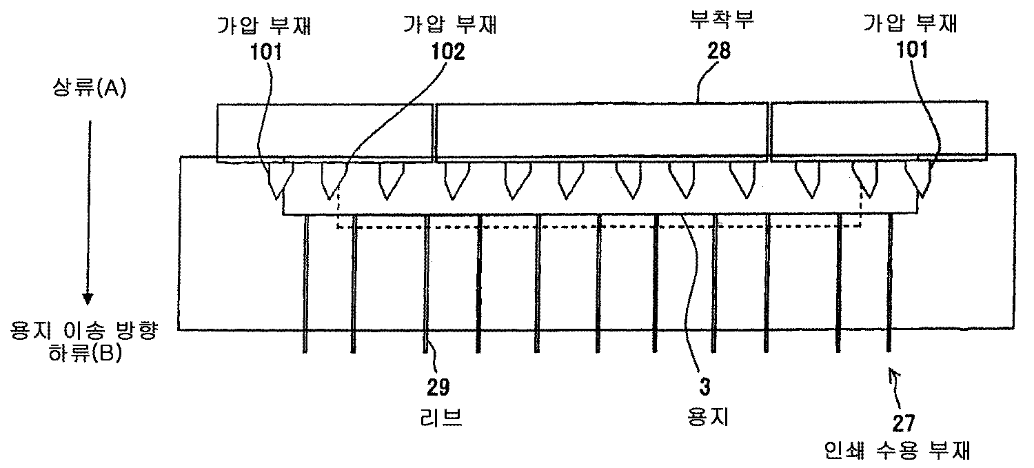
도 2를 참조하면, 인쇄 수용 부재(27)는 다수개의 리브(지지 부재)(29)를 제공한다. 리브(29)는 용지(3)와 기록 헤드(14) 사이에 기설정된 간극을 형성하도록 배치된다. 도 2에 도시된 바와 같이, 다수개의 리브(29) 중 최외측의 리브는 용지의 측면 에지의 약간 내측에 위치한다. 바람직하게, 최외측 리브(29)와 대응되는 용지(3)의 측면 에지 사이의 거리는 10mm 이하이다. 더욱 바람직하게 이 사이의 거리는 5mm 이하이다. 부착부(attachment portion, 28)는 아래에서 상세하게 설명될 다수개의 가압 부재(101)(102)를 제공한다.Referring to FIG. 2, the
인쇄 수용 부재(27)로 이송된 용지(3)는 가압 부재(101)(102)에 의해 아래방향으로 가압되고, 인쇄 수용 부재(17)에 구비된 리브(29)의 상부 또는 리브(29)를 따라 이송된다. 이러한 방식으로, 용지(3)와 인쇄 헤드(14) 사이에 기설정된 간극이 형성된다. 잉크 헤드(14)로부터 토출된 잉크 방울은 용지(3)의 상면에 점착되고, 따라서 기설정된 화상이 용지(3) 위에 형성된다.The
다수개의 가압부재(101)(102), 양 측 위의 최외측 가압부재(101)(제 1,2 용지 가압 부재)는 용지(3)의 각각의 측부를 아래 방향으로 가압할 수 있다. 이에 의하여 용지(3)의 측부가 최외측 리브(29)의 외측 영역에서 아래 방향으로 굽어지게 되고(도 4에 도시), 이에 의하여 측부가 들어 올려지는 것이 방지된다. 그런데, 여기에서 "측부"는 용지 이송 방향을 따라 연장된 용지의 에지에 인접한 영역으로 이해될 수 있다.The plurality of pressing
부가적으로 양 측부에서의 용지(3)의 이와 같은 굽어짐 때문에, 용지(3)는 심지어 두 개의 인접한 리브 사이에서 평평함이 유지될 수 있고, 따라서 용지(3)와 기록 헤드(14) 사이의 일정한 간극을 유지할 수 있다. 더욱이, 심지어 용지(3)가 잉크 방울을 흡수한 후 부풀어 오르더라도 용지(3)가 기록 헤드(14)에 접촉되는 것이 방지된다. 이에 의하여 용지 위의 화상의 품질 저하를 방지하고, 기록 헤드(14)가 파손되는 것을 방지한다.In addition, because of this bending of the
상기한 바와 같이, 기록 헤드(14)에 대항하도록 인쇄 수용 부재(27) 위에 배치된 다수개 리브(29), 용지(3)의 측면 부분을 아래 방향으로 가압하도록 배치되는 가압 부재(101), 이러한 제한 없는 실시예에서 모든 두 개의 인접한 리브 사이에 배치되는 가압부재(102)의 단순한 구성 때문에, 용지(3)가 기록 헤드(14)에 접촉하는 것이 방지된다.As described above, the plurality of
[가압 부재(pressing member)][Pressing member]
다음으로, 부착부(28)에 부착된 가압 부재(101)(102)가 상세하게 설명된다. 이 실시예에 따른 각 가압 부재(101)(102)는 도 3에 도시된 바와 같이, 인쇄 수용 부재(17)의 상류 측(또는 도 3에 도시된 "A" 측) 부착부(28)에 부착되고, 하류 측(또는 도 3에 도시된 "B" 측)을 향하여 연장된다. 특히, 가압 부재(101)는 최외측 리브(29)의 외측에 배치되고, 상술한 바와 같이 이에 의하여 용지(3)의 측면 부분이 들어 올려지는 것이 방지된다.Next, the
더불어, 도 3에 도시된 바와 같이 가압 부재(101)는 서로 대칭되도록 배치되고, 용지(3)는 양 측부에서 실질적으로 동일한 정도로 들어 올려지는 것이 방지된다.In addition, as shown in Fig. 3, the
그런데, 도 3에 도시된 용지(3)보다 작은 폭을 가진 용지가 이송될 때, 가압 부재(101)의 내측에 위치하는 다른 가압 부재(예를 들어 가압부재(102))는 용지의 측부를 아래 방향으로 가압할 수 있다. 예를 들면, 가압 부재(102)(제3 용지 가압 부재)는 도 3에서 점선에 의해 도시된 용지의 측부를 아래 방향으로 가압할 수 있다. 따라서, 폭이 좁은 용지도 또한 양 측부에서 위쪽 방향으로 들어 올려지는 것이 방지될 수 있다.By the way, when a paper having a width smaller than that of the
그런데, 용지는 용지의 중심이 인쇄 수용 부재(27)의 중심점에 일치하도록 인쇄 수용 부재(27)에 놓이기 때문에, 도 3에 도시된 가압 부재(101)(102)는 인쇄 수용 부재(27)의 중심점에 대하여 대칭적으로 배열된다. 반대로, 용지가 왼쪽 정렬일 때 알맞도록 가압 부재(101)(102)는 도 8에 도시된 바와 같이 비대칭적으로 배치될 수 있다. 특히, 실선에 의해 도시된 용지(3)보다 더 좁은 폭의 도 8의 점선에 의해 도시된 용지는 왼쪽 정렬되도록 이송되고, 좁은 폭의 용지의 오른쪽 에지는 가압 부재(102) 중 어느 하나에 의해 아래 방향으로 가압될 수 있다.By the way, since the paper is placed on the
도 5(a) 및 도 5(b)는 본 발명의 일실시예에 따른 가압부재(101)의 다른 예들을 나타낸다. 도 5(a)에 도시된 바와 같이, 가압 부재(101)는 용지 이송 방향에서 아래 방향의 지점에 있는 말단 지점(B)을 가진다. 말단 지점(B)은 외측방향(도 5(a)에서 왼쪽방향)에, 그리고 가압 부재(101)의 상류측 위의 중심점(A)으로부터 하류에 위치한다.5 (a) and 5 (b) show other examples of the
더불어, 말단 지점(B)은 용지 에지(paper edge, 점선) 외측에 배치된다. 더욱이, 말단 지점(B) 뿐만 아니라 적어도 말단 지점(B)의 하류 측에 있는 부분도 용지 에지 외측에 배치된다.In addition, the end point B is disposed outside the paper edge (dashed line). Moreover, not only the end point B but also at least the portion downstream of the end point B is disposed outside the paper edge.
도 5(b)에 도시된 바와 같이, 다른 예로서 가압 부재(101)는 외측방향(도 5(b)에서 좌측방향)과 말단 지점(C)의 상류 측의 모퉁이 지점(D)으로부터 하류에 위치하는 말단 지점(C)을 가진다.As shown in FIG. 5 (b), as another example, the pressing
도 6(a) 내지 도 6(f)는 가압 부재(101)의 또 다른 실시예를 나타낸다. 여기에서 도시되는 모든 가압 부재(101)는 용지의 왼쪽 측부를 아래 방향으로 가압하기 위하여 배치된다.6 (a) to 6 (f) show another embodiment of the
도 5(a) 및 도 5(b), 및 도 6(a) 내지 도 6(f)에 도시된 이와 같은 형상을 가진 가압 부재(101)는 용지가 아래 방향으로 진행될 때 용지의 측부에 더 큰 가압력을 제공할 수 있고, 이에 의하여 용지의 측부가 윗쪽으로 들어 올려지는 것을 확 실하게 방지한다.The pressing
더욱이, 심지어 용지의 측부가 용지 이송 방향에 대해 가로지르는 방향으로 약간 이동될 때, 용지의 에지가 가압 부재(101)에 접촉될 수 있고, 아래 방향으로 가압될 수 있다. 따라서, 용지(3)의 측부는 더 약한 가압력에 의해 아래 방향으로 굽어질 수 있다.Moreover, even when the side of the paper is slightly moved in the direction transverse to the paper conveying direction, the edge of the paper can contact the
더하여, 쉽게 굽어지고 위쪽으로 감겨지는 용지의 측부가 아래 방향으로 가압됨으로써 용지가 오염되거나 용지 걸림되는 것이 방지된다.In addition, the side of the sheet which is easily bent and wound upward is pressed downwards to prevent the paper from being contaminated or jammed.
더불어, 가압 부재(101)는 가압 부재의 상류측 부분이 가압 부재의 하류측 부분보다 더 좁기 때문에 가압 부재(101)는 더 약한 힘으로 용지의 측부를 아래 방향으로 가압할 수 있고, 이에 의하여 용지가 전체적으로 평평함을 유지할 수 있고, 따라서 더 나은 인쇄 품질이 제공된다. 만약 가압력이 너무 강하면, 용지는 평평함을 유지할 수 없고, 더 강한 힘은 리브 사이에 용지가 남게 되는 원인이 될 수 있기 때문에 기록 헤드(14, 도 1)와의 관계에서 용지 평평도를 유지하는 것은 어려운 것이다.In addition, the pressing
더욱이, 용지의 측부에 인접하게 배치된 최외측 리브(29)는 용지 평평도를 유지하도록 도울 수 있고, 이에 의하여 더 나은 화상 품질을 제공한다. 더욱이 최외측 리브(29)의 외측에 가압 부재(101)가 배치되므로, 가압 부재(101)는 용지의 측부가 윗쪽으로 들어 올려지는 것을 방지할 수 있다.Moreover, the
도 7(a) 내지 도 7(d)는 가압 부재(101)의 다양한 다른 실시예를 나타낸다. 특히 도 7(a) 내지 도 7(c)는 용지 이송 방향을 따라 동일한 폭을 가진 가압 부재 를 나타내고, 가압 부재는 도 5(a) 및 도 5(b), 도 6(a) 내지 도 6(f)에 도시된 가압 부재와 다르다.7A-7D show various other embodiments of the
더욱이, 도 7(a)에 도시된 바와 같이, 가압 부재(101)는 가압 부재의 후방(또는 하류) 끝단의 중심 지점(B)이 용지 에지 외측에 위치하고, 반면에 가압 부재의 전방(또는 상류) 끝단의 중심 지점(A)이 점선에 의하여 도시된 용지 에지 상부에 실질적으로 위치하도록 배치된다.Furthermore, as shown in Fig. 7A, the pressing
도 7(b)에서 가압 부재(101)는 가압 부재의 후방(또는 하류) 끝단의 중심 지점(B)이 용지 에지 외측에 위치하고, 반면에 가압부재의 전방(또는 상류) 끝단의 중심 지점(A)이 용지 에지 내측에 위치하도록 배치된다.In FIG. 7B, the pressing
도 7(c)에서 가압 부재(101)는 중심 지점(A)(B)이 용지 에지 내측에 위치하도록 배치된다. 비록 지점(A)뿐만 아니라 지점(B)이 이와 같은 경우처럼 용지 에지 내측에 위치한다 할지라도, 적어도 가압부재(101)의 일부분은 용지 에지로부터 외측으로 연장될 수 있다. 따라서, 이러한 가압부재(101)는 용지 에지를 아래 방향으로 또한 가압할 수 있다.In Fig. 7 (c), the pressing
도 7(d)는 가압 부재(101)는 직사각형의 형상을 가지고, 가압부재의 후방(또는 하류) 끝단의 중심 지점(B)과 가압부재의 전방(또는 상류) 끝단의 중심 지점(A) 모두가 용지의 에지 위에 실질적으로 위치하도록 배치된다.7 (d) shows that the
심지어 도 7(a) 내지 도 7(d)에 도시된 이러한 가압 부재(101)는 가압 부재(101)가 인쇄 수용 부재(27)의 양 측에 배치될 때 용지의 양 측부에서 용지가 고르게 윗쪽으로 들어 올려지는 것을 방지할 수 있다. 더욱이, 이와 같은 가압 부 재(101)는 더 좁은 폭의 용지의 측부가 윗쪽으로 들어 올려지는 것을 방지할 수 있다.Even this pressing
[가압량 제한 부재(pressing amount limiting member)][Pressing amount limiting member]
다음으로, 본 발명의 일실시예에 따른 가압량 제한 부재가 설명된다. 앞으로의 실시예에서, 가압 부재(101)는 최외측 리브(29)의 외측에 있는 용지를 아래 방향으로 가압한다. 더불어, 가압부재(101)의 내측 면에 다수개의 가압 부재(102)가 배치되므로, 심지어 더 좁은 폭의 용지가 사용되더라도, 용지는 양 측부에서 아래 방향으로 굽어질 수 있다(도 3).Next, the pressing amount limiting member according to an embodiment of the present invention will be described. In a future embodiment, the pressing
그러나, 다수개의 가압 부재(102)는 모든 인접한 리브(29) 사이에서 대부분 용지를 아래 방향으로 가압하고, 이에 의하여 기록 헤드(14)와의 관계에서 평평함을 유지해야 하는 용지가 불필요하게 굽어지게 될 수 있다. 이와 같은 불필요한 굽어짐을 방지하기 위하여 가압량 제한 부재(30)가 이 실시예에서 제공된다. 즉, 가압 부재(102)에 의해 야기된 용지의 총 가압량은 가압량 제한 부재(30)의 높이를 조정함으로써 조정될 수 있다.However, the plurality of pressing
가압량 제한 부재(30)는 인쇄 수용 부재(27) 위에 배치된다. 특히, 가압량 제한 부재(30)는 도 9(a) 내지 도 9(c)에 도시된 바와 같이 가압 부재(101),(102)와 관련하여 세 곳에 배치될 수 있고, 가압량 제한 부재(30)가 가압 부재(102)에 의해 용지(3)를 가압하는 총 양을 제한할 수 있는 한 위치가 세 곳으로 엄격하게 제한될 수 없다.The pressurizing
도 9(a)에서, 가압량 제한 부재(30)는 리브(29)와 리브(29) 사이에서 가압 부재(102)의 외측(또는 좌측)에 배치된다. 도 9(a)에서, 가압량 제한 부재(30)는 가압 부재(102)의 아래에 배치된다. 다시 말해, 가압량 제한 부재(30)는 가압 부재(102)에 의해 아래 방향으로 가압되는 용지 부분이 가압량 제한 부재(30)에 의해서 지지될 수 있도록 배치된다. 도 9(c)에서, 가압량 제한 부재(30)는 리브(29)와 리브(29) 사이에서 가압 부재(102) 내측(또는 우측)에 배치된다. 도 9(a) 내지 도 9(c)에 도시된 바와 같이 배치되는 가압량 제한 부재(30)는 이하에서 상세히 설명된다.In FIG. 9A, the pressing
첫번째로, 가압 부재(102)의 외측에 배치되는 가압량 제한 부재(30)는 도 9(a), 도 10, 도 11을 참조하여 설명된다. 도 10은 각각의 다른 가압량 제한 부재(30)가 대응하는 가압부재(102)의 외측에 배치되는 것을 나타내는 설명도이다. 도 11은 각각의 다른 가압량 제한 부재(30)가 대응하는 가압 부재(102)의 외측에 배치되는 인쇄 수용 부재(27)를 나타내는 평면도이다. 리브(29), 가압량 제한 부재(30), 및 세번째 용지 가압 부재(102)가 용지(30)의 측면 에지로부터 중심 방향으로 이와 같은 순서로 배치되는 것은 도 10과 도 11로부터 이해될 수 있다. 가압 부재(102)에 의한 용지(3)의 가압량은 가압량 제한 부재(30)가 배치되는 높이를 조정함으로써 조정될 수 있다.First, the pressing
도 10에 도시된 바와 같이, 가압량 제한 부재(30)는 리브(29)보다 더 낮은 높이(수직한 길이)를 가진다. 다시 말해, 가압량 제한 부재(30)는 리브(29)보다 더 높은 높이 또는 같은 높이를 가질 필요가 없다. 왜냐하면 가압량 제한 부재(30)는 용지(3)와 기록 헤드(14) 사이의 간극을 조정하기 위해 배열되지 않고, 반면에 인 쇄 수용 부재(27)에 배치된 리브(29)는 간극을 형성하기 위해 배열되기 때문이다. 더하여, 가압량 제한 부재(30)가 가압부재(102)에 의해 용지(3)를 가압하는 양을 제한할 수 있는 한 가압량 제한 부재(30)의 높이는 특별한 값으로 제한되지 않는다.As shown in FIG. 10, the pressing
다음으로, 가압 부재(102)의 아래에 배치되는 가압량 제한 부재(30)는 도 9(b)와 도 12 내지 도 16을 참조하여 설명된다. 도 12는 각각의 가압 부재(102)의 아래에 배치되는 다른 가압량 제한 부재(30)를 나타내는 다른 설명도이다. 도 13은 각각의 가압 부재(102) 아래에 배치되는 다른 가압량 제한 부재(30)가 있는 인쇄 수용 부재(27)를 나타내는 평면도이다. 더욱이, 도 14는 용지(3)가 더 넓고, 더 넓은 용지의 용지 에지가 가압부재(101) 아래로 연장된 상태를 나타낸다. 가압 부재(102)에 의한 용지(3)를 가압하는 양은 가압량 제한 부재(30)가 배치되는 높이를 조정함으로써 조정될 수 있다.Next, the pressing
비록 도 12 내지 도 14 각각이 가압 부재(101)의 아래에 배치되는 다른 가압량 제한 부재(30)를 나타내지만, 이와 같은 가압량 제한 부재(30)는 도 15 및 도 16에 도시된 바와 같이 항상 필수적인 것은 아니다. 심지어 이와 같은 경우에, 용지의 측부는 가압 부재(101)에 의해 아래 방향으로 가압될 수 있고, 가압부재(102)에 의한 용지(3)의 가압량은 가압 부재(102) 아래에 가압량 제한 부재(30)에 의해 제한될 수 있기 때문에 용지(3)는 기록 헤드(14)와의 관계에서 평평함이 유지될 수 있다.Although each of FIGS. 12 to 14 shows another pressing
다음으로, 가압 부재(102) 내측(또는 우측)에 배치되는 가압량 제한 부 재(30)는 도 9(c), 도 17 내지 도 20을 참조하여 설명된다. 도 17은 다른 가압량 제한 부재(30) 각각이 대응하는 가압 부재(102) 내측에 배치되는 것을 나타내는 설명도이다. 도 18은 다른 가압량 제한 부재(30) 각각이 대응하는 가압 부재(102)의 내측에 배치된 인쇄 수용 부재(27)를 나타내는 평면도이다. 세번째 가압 부재(102) 및 가압량 제한 부재(30)는 용지(3)의 측면 에지로부터 중심방향으로 이와 같은 순서로 배치되는 것은 도 17 및 도 18로부터 이해될 수 있다. 가압 부재(102)에 의한 용지(3)를 가압하는 양은 가압량 제한 부재(30)가 배치되는 높이를 조정함으로써 조정될 수 있다.Next, the pressing
비록 도 17 및 도 18이 가압 부재(101)와 최외측 리브(19) 사이에 배치된 가압량 제한 부재(30)를 나타내지만, 이와 같은 가압량 제한 부재(30)은 도 19 및 도 20에 도시된 바와 같이 항상 필수적인 것은 아니다. 이러한 경우에, 가압 부배(101)는 용지(3)의 측부를 아래 방향으로 가압할 수 있다. 게다가, 가압 부재(102)에 의한 용지(3)를 가압하는 양은 기록 헤드(14)와의 관계에서 용지(3)가 평평함이 유지되도록 가압 부재(102) 내측에 배치된 가압량 제한 부재(30)에 의해 제한될 수 있다.Although FIGS. 17 and 18 show the pressing
도 21(a) 및 도 21(b)를 참조하여, 용지(3)의 크기에 의존하여 가압 부재(101)(102) 및 가압량 제한 부재(30)가 어떻게 다르게 작용할 수 있는지가 이하에서 설명된다.Referring to Figs. 21A and 21B, how the
도 21(a)는 가압 부재(102)에 의해 아래 방향으로 가압될 용지보다 더 큰 용지(3)가 가압량 제한 부재(30)로 이송될 때, 가압량 제한 부재(30)가 가압 부재(102)에 의해 용지(3)를 가압하는 양이 제한되도록 어떻게 작용하는지를 나타내는 설명도이다. 이러한 경우에, 더 큰 용지(3)의 측부는 측부가 들어 올려지는 것을 방지하기 위하여 가압 부재(102)가 아니라 가압 부재(101)에 의해 아래 방향으로 가압되고, 더 큰 용지(3)의 인쇄 영역은 가압 부재(102)와 가압부재(102)에 의한 더 큰 용지(3)를 가압하는 양을 제한하는 가압량 제한 부재(30)에 의해 기록 헤드(14, 도 1)와의 관계에서 평평함이 유지되며, 이에 의해서 용지 상에 더 나은 인쇄품질이 제공된다.21 (a) shows that when the
반면에, 도 21(b)에 도시된 바와 같이 도 21(a)에 도시된 용지(3)보다 더 좁은 폭의 용지(3)가 인쇄 수용 부재(27, 도 11)로 이송되면, 더 좁은 폭의 용지(3)는 가압 부재(102)에 의해 아래 방향으로 가압될 수 있다. 이러한 경우, 측부에는 어떠한 화상도 인쇄되지 않기 때문에 용지(3)의 측부의 상대적으로 큰 영역은 가압 부재(102)에 의해 아래 방향으로 가압될 수 있다.On the other hand, when the
더불어, 다수개의 가압량 제한 부재(X)가 대응되는 가압 부재(102)와 대응되는 가압 부재(101)(102)의 아래의 다수개의 가압량 제한 부재(Y) 외측에 배치되는 본 발명에 따른 다른 실시예에서로서 고려될 수 있다.In addition, according to the present invention, a plurality of pressing amount limiting members (X) are disposed outside the plurality of pressing amount limiting members (Y) below the corresponding pressing members (102) and corresponding pressing members (101) (102). In other embodiments.
가압량 제한 부재(X)는 (도 22(a)와 같이) 용지(3)의 에지가 가압 부재(101)에 이를 때 연관된 가압 부재(102)에 의해 용지(3)을 가압하는 양을 제한하도록 한다. 따라서, 용지(3)는 더 나은 인쇄 품질을 위하여 가압량 제한 부재(X)가 가압량을 제한하는 영역에서 기록 헤드(14, 도1)와의 평평함이 유지될 수 있다. 더욱이 가압량 제한 부재(X)(Y)는 가압량 제한 부재의 높이를 조정함으로써 가압량 제한 효과를 나타낼 수 있다. 따라서, 용지(3)는 기록 헤드(14, 도1)와의 관계에서 평평함이 유지될 수 있다.The pressing amount limiting member X limits the amount of pressing of the
반면에, 좁은 폭의 용지 에지가 가압부재(101)에 이르지 않는 용지가 이송되면, 용지의 측부를 아래 방향으로 가압하는 연관된 가압 부재(102)의 아래에 배치된 가압량 제한 부재(Y)는 가압 부재(102)에 의해 용지(3)를 가압하는 양을 제한할 수 있다. 더욱이, 가압량 제한 부재(예를 들어, 30, X, Y)의 높이의 조정은 가압 부재(102)에 의한 제한양을 감소 또는 증가시킬 수 있다.On the other hand, when a sheet of paper whose narrow width does not reach the
상기한 바와 같이, 다수개의 가압량 제한 부재(30, X, Y)가 제공되는 일실시예에 따르면, 가압량 제한 효과는 사용자의 필요에 의해 적절하게 나타내어 질 수 있다.As described above, according to one embodiment in which a plurality of pressurizing
한편, 본 발명은 특히 여기에 포함된 실시예들에 제한되지 않고, 수반되는 청구항으로 설명한 본 발명의 범위를 이탈함이 없이 다양한 변경 및 수정이 적용될 수 있다.On the other hand, the present invention is not particularly limited to the embodiments included herein, and various changes and modifications may be applied without departing from the scope of the present invention described in the accompanying claims.
본 명세서는 일본 특허청에 2006.05.26 출원된 일본 특허 출원 제2006-146861, 2007.03.14 출원된 일본 특허 출원 제2007-065640에 기초하고, 이 명세서의 전체 내용은 참조 문헌이 반영되었다.This specification is based on Japanese Patent Application No. 2006-146861 for which it applied to Japan Patent Office on May 26, 2006-146861, and 2007.03.14 for which the whole content of this specification has reflected the reference document.
Claims (24)
Applications Claiming Priority (5)
| Application Number | Priority Date | Filing Date | Title |
|---|---|---|---|
| JP2006146861 | 2006-05-26 | ||
| JPJP-P-2006-00146861 | 2006-05-26 | ||
| JPJP-P-2007-00065640 | 2007-03-14 | ||
| JP2007065640A JP5089203B2 (en) | 2006-05-26 | 2007-03-14 | Paper conveying apparatus, image forming apparatus, and ink jet recording apparatus |
| KR2007060753 | 2007-05-22 |
Publications (1)
| Publication Number | Publication Date |
|---|---|
| KR100972749B1 true KR100972749B1 (en) | 2010-07-29 |
Family
ID=38778564
Family Applications (2)
| Application Number | Title | Priority Date | Filing Date |
|---|---|---|---|
| KR1020087002008A KR20080021813A (en) | 2006-05-26 | 2007-05-22 | Paper conveying apparatus, image forming apparatus and ink-jet recording apparatus |
| KR1020087002008A KR100972749B1 (en) | 2006-05-26 | 2007-05-22 | Paper conveying apparatus, image forming apparatus and ink-jet recording apparatus |
Family Applications Before (1)
| Application Number | Title | Priority Date | Filing Date |
|---|---|---|---|
| KR1020087002008A KR20080021813A (en) | 2006-05-26 | 2007-05-22 | Paper conveying apparatus, image forming apparatus and ink-jet recording apparatus |
Country Status (6)
| Country | Link |
|---|---|
| US (2) | US8256764B2 (en) |
| EP (1) | EP2021184B1 (en) |
| JP (1) | JP5089203B2 (en) |
| KR (2) | KR20080021813A (en) |
| CN (1) | CN101331024B (en) |
| WO (1) | WO2007139043A1 (en) |
Families Citing this family (20)
| Publication number | Priority date | Publication date | Assignee | Title |
|---|---|---|---|---|
| US7458575B2 (en) * | 2004-08-26 | 2008-12-02 | Oki Data Corporation | Medium feeding device with a convex profiled cross section |
| JP2010253795A (en) * | 2009-04-24 | 2010-11-11 | Seiko Epson Corp | Recording apparatus |
| JP5139463B2 (en) * | 2010-03-30 | 2013-02-06 | 株式会社沖データ | Paper feeding device and image forming apparatus |
| JP2012245626A (en) * | 2011-05-25 | 2012-12-13 | Seiko Epson Corp | Recorder |
| JP5835645B2 (en) * | 2011-06-28 | 2015-12-24 | 株式会社リコー | Guide structure and image forming apparatus |
| JP5760987B2 (en) | 2011-11-28 | 2015-08-12 | ブラザー工業株式会社 | Inkjet recording device |
| JP5696651B2 (en) * | 2011-11-28 | 2015-04-08 | ブラザー工業株式会社 | Inkjet recording device |
| JP6241019B2 (en) * | 2012-04-17 | 2017-12-06 | ブラザー工業株式会社 | Inkjet printer |
| JP5958053B2 (en) * | 2012-04-27 | 2016-07-27 | ブラザー工業株式会社 | Image recording device |
| JP6111550B2 (en) | 2012-07-31 | 2017-04-12 | ブラザー工業株式会社 | Inkjet recording device |
| JP5932737B2 (en) * | 2013-08-30 | 2016-06-08 | 京セラドキュメントソリューションズ株式会社 | Inkjet recording device |
| JP2015150823A (en) * | 2014-02-18 | 2015-08-24 | セイコーエプソン株式会社 | Recording device and method for inhibiting contact between pressing member and recording part |
| JP6347138B2 (en) | 2014-03-31 | 2018-06-27 | ブラザー工業株式会社 | Image recording device |
| JP6435747B2 (en) * | 2014-09-25 | 2018-12-12 | ブラザー工業株式会社 | Image recording device |
| JP5900674B2 (en) * | 2015-02-05 | 2016-04-06 | ブラザー工業株式会社 | Image recording device |
| JP6451404B2 (en) * | 2015-02-27 | 2019-01-16 | ブラザー工業株式会社 | Inkjet recording device |
| WO2019005028A1 (en) * | 2017-06-28 | 2019-01-03 | Hewlett-Packard Development Company, L.P. | Mark mitigating device |
| JP7094680B2 (en) * | 2017-09-29 | 2022-07-04 | キヤノン株式会社 | Image forming device |
| US10647133B2 (en) * | 2017-10-31 | 2020-05-12 | Seiko Epson Corporation | Medium transporting device and recording apparatus |
| US11734983B1 (en) * | 2018-12-18 | 2023-08-22 | Cummins-Allison Corp. | Banknote transport mechanisms and methods |
Citations (2)
| Publication number | Priority date | Publication date | Assignee | Title |
|---|---|---|---|---|
| JPH0948161A (en) * | 1994-09-02 | 1997-02-18 | Canon Inc | Ink jet recorder |
| JP2000071532A (en) * | 1998-08-27 | 2000-03-07 | Canon Inc | Ink-jet recording apparatus |
Family Cites Families (17)
| Publication number | Priority date | Publication date | Assignee | Title |
|---|---|---|---|---|
| JPS59188467A (en) | 1983-04-12 | 1984-10-25 | Seiko Epson Corp | Paper-pressing mechanism for ink jet printer |
| US4704422A (en) | 1986-09-02 | 1987-11-03 | Dow Corning Corporation | Silicone emulsion having improved freeze/thaw resistance |
| JPH0618376Y2 (en) * | 1986-10-24 | 1994-05-11 | 富士ゼロックス株式会社 | Heat and pressure fixing device for electronic copiers |
| KR970000610B1 (en) * | 1992-06-04 | 1997-01-16 | 가부시키가이샤 테크 | Sheet delivery mechanism for a printer |
| JP3698740B2 (en) * | 1993-06-30 | 2005-09-21 | 松下電器産業株式会社 | Paper transport device |
| JP2616407B2 (en) | 1993-10-28 | 1997-06-04 | 日本電気株式会社 | Dot impact printer device |
| JPH07132659A (en) | 1993-11-11 | 1995-05-23 | Tec Corp | Sheet delivering device for printer |
| JPH0924650A (en) | 1995-07-12 | 1997-01-28 | Tec Corp | Linear ink jet printer |
| US5904350A (en) * | 1997-01-31 | 1999-05-18 | Tektronix, Inc. | Apparatus and method for deskewing media in a printer |
| JP3658159B2 (en) * | 1997-11-13 | 2005-06-08 | キヤノン株式会社 | Recording device |
| JP3865355B2 (en) | 2000-03-16 | 2007-01-10 | 株式会社リコー | Inkjet recording device |
| JP2002036649A (en) | 2000-07-21 | 2002-02-06 | Canon Inc | Ink jet recording apparatus |
| JP3979903B2 (en) | 2002-09-03 | 2007-09-19 | ローランドディー.ジー.株式会社 | Printer paper presser mechanism |
| JP4073008B2 (en) * | 2002-09-17 | 2008-04-09 | キヤノン株式会社 | Recording device |
| JP2004322632A (en) * | 2003-04-07 | 2004-11-18 | Seiko Epson Corp | Printed medium lift avoiding device, printing device, and liquid injection device |
| JP2005047227A (en) * | 2003-07-31 | 2005-02-24 | Canon Inc | Double-sided recording device |
| JP2005314064A (en) * | 2004-04-28 | 2005-11-10 | Canon Inc | Image forming device |
-
2007
- 2007-03-14 JP JP2007065640A patent/JP5089203B2/en active Active
- 2007-05-22 CN CN2007800007390A patent/CN101331024B/en active Active
- 2007-05-22 WO PCT/JP2007/060753 patent/WO2007139043A1/en active Application Filing
- 2007-05-22 KR KR1020087002008A patent/KR20080021813A/en unknown
- 2007-05-22 EP EP07744187A patent/EP2021184B1/en active Active
- 2007-05-22 US US11/996,566 patent/US8256764B2/en active Active
- 2007-05-22 KR KR1020087002008A patent/KR100972749B1/en active IP Right Grant
-
2012
- 2012-07-27 US US13/559,848 patent/US20120292848A1/en not_active Abandoned
Patent Citations (2)
| Publication number | Priority date | Publication date | Assignee | Title |
|---|---|---|---|---|
| JPH0948161A (en) * | 1994-09-02 | 1997-02-18 | Canon Inc | Ink jet recorder |
| JP2000071532A (en) * | 1998-08-27 | 2000-03-07 | Canon Inc | Ink-jet recording apparatus |
Also Published As
| Publication number | Publication date |
|---|---|
| EP2021184A4 (en) | 2009-06-24 |
| EP2021184B1 (en) | 2012-04-18 |
| KR20080021813A (en) | 2008-03-07 |
| US8256764B2 (en) | 2012-09-04 |
| WO2007139043A1 (en) | 2007-12-06 |
| JP5089203B2 (en) | 2012-12-05 |
| EP2021184A1 (en) | 2009-02-11 |
| CN101331024A (en) | 2008-12-24 |
| US20120292848A1 (en) | 2012-11-22 |
| JP2008001522A (en) | 2008-01-10 |
| CN101331024B (en) | 2012-01-25 |
| US20090121422A1 (en) | 2009-05-14 |
Similar Documents
| Publication | Publication Date | Title |
|---|---|---|
| KR100972749B1 (en) | Paper conveying apparatus, image forming apparatus and ink-jet recording apparatus | |
| US8197056B2 (en) | Image forming apparatus having line-type recording head | |
| US20090015614A1 (en) | Ink jet print head, ink jet printing apparatus, and method for manufacturing ink jet print head | |
| JP5703267B2 (en) | Inkjet recording device | |
| US6666536B2 (en) | Ink jet device with movable platen | |
| US9694606B2 (en) | Ink-jet recording apparatus | |
| US9511607B2 (en) | Printhead protection device for direct-to-paper continuous-feed inkjet printer | |
| JP2006247884A (en) | Platen, recording apparatus and liquid jetting device | |
| KR100571965B1 (en) | Inkjet printing head and inkjet printer using the same | |
| JP7064923B2 (en) | Seat supply device | |
| JP2010228286A (en) | Print controller, line head printer, and dot size determining method | |
| JP4869412B2 (en) | Inkjet recording apparatus and image forming apparatus | |
| JP2020506134A (en) | Roller feed mechanism for printer with multiple printheads | |
| JP3828305B2 (en) | Inkjet recording device | |
| JP4308213B2 (en) | Image forming apparatus | |
| JP2006182033A (en) | Inkjet recording device and image forming device | |
| JP5344068B2 (en) | Paper transport device and image forming apparatus | |
| JP2007176002A (en) | Recording device of line-head type | |
| JP4452309B2 (en) | Image forming apparatus | |
| JP2021030526A (en) | Ink jet recording device | |
| JP2007290801A (en) | Inkjet printer and image forming device | |
| US11825048B2 (en) | Rotatable media ramp for automatic document feeder | |
| JP3865355B2 (en) | Inkjet recording device | |
| US20230166539A1 (en) | Printing apparatus | |
| JP2007276907A (en) | Recorded medium tray and recording device |
Legal Events
| Date | Code | Title | Description |
|---|---|---|---|
| A201 | Request for examination | ||
| E902 | Notification of reason for refusal | ||
| E701 | Decision to grant or registration of patent right | ||
| GRNT | Written decision to grant | ||
| FPAY | Annual fee payment |
Payment date: 20130711 Year of fee payment: 4 |
|
| FPAY | Annual fee payment |
Payment date: 20140711 Year of fee payment: 5 |
|
| FPAY | Annual fee payment |
Payment date: 20150709 Year of fee payment: 6 |
|
| FPAY | Annual fee payment |
Payment date: 20160714 Year of fee payment: 7 |
|
| FPAY | Annual fee payment |
Payment date: 20190711 Year of fee payment: 10 |