KR100885180B1 - Substrate support unit, and apparatus and method for treating substrate with the same - Google Patents
Substrate support unit, and apparatus and method for treating substrate with the same Download PDFInfo
- Publication number
- KR100885180B1 KR100885180B1 KR1020060135283A KR20060135283A KR100885180B1 KR 100885180 B1 KR100885180 B1 KR 100885180B1 KR 1020060135283 A KR1020060135283 A KR 1020060135283A KR 20060135283 A KR20060135283 A KR 20060135283A KR 100885180 B1 KR100885180 B1 KR 100885180B1
- Authority
- KR
- South Korea
- Prior art keywords
- substrate
- swirl flow
- chuck plate
- gas
- flow generator
- Prior art date
Links
- 239000000758 substrate Substances 0.000 title claims abstract description 210
- 238000000034 method Methods 0.000 title claims abstract description 139
- 238000002347 injection Methods 0.000 claims description 38
- 239000007924 injection Substances 0.000 claims description 38
- 239000012530 fluid Substances 0.000 claims description 25
- 238000003672 processing method Methods 0.000 claims description 8
- 239000007921 spray Substances 0.000 claims description 7
- 239000004065 semiconductor Substances 0.000 abstract description 4
- 238000005188 flotation Methods 0.000 abstract description 2
- 235000012431 wafers Nutrition 0.000 description 98
- 239000007789 gas Substances 0.000 description 89
- 239000007788 liquid Substances 0.000 description 33
- 238000011084 recovery Methods 0.000 description 17
- 238000004140 cleaning Methods 0.000 description 11
- 238000005530 etching Methods 0.000 description 5
- 238000004519 manufacturing process Methods 0.000 description 5
- 238000001035 drying Methods 0.000 description 3
- 239000000126 substance Substances 0.000 description 3
- 238000000576 coating method Methods 0.000 description 2
- 239000000356 contaminant Substances 0.000 description 2
- 238000010586 diagram Methods 0.000 description 2
- 238000009826 distribution Methods 0.000 description 2
- 238000012986 modification Methods 0.000 description 2
- 230000004048 modification Effects 0.000 description 2
- 239000002245 particle Substances 0.000 description 2
- 229920002120 photoresistant polymer Polymers 0.000 description 2
- 230000001105 regulatory effect Effects 0.000 description 2
- 239000011248 coating agent Substances 0.000 description 1
- 238000011109 contamination Methods 0.000 description 1
- 230000000694 effects Effects 0.000 description 1
- 239000011521 glass Substances 0.000 description 1
- 239000011261 inert gas Substances 0.000 description 1
- 239000003960 organic solvent Substances 0.000 description 1
- 238000001179 sorption measurement Methods 0.000 description 1
Images


Classifications
-
- H—ELECTRICITY
- H01—ELECTRIC ELEMENTS
- H01L—SEMICONDUCTOR DEVICES NOT COVERED BY CLASS H10
- H01L21/00—Processes or apparatus adapted for the manufacture or treatment of semiconductor or solid state devices or of parts thereof
- H01L21/67—Apparatus specially adapted for handling semiconductor or electric solid state devices during manufacture or treatment thereof; Apparatus specially adapted for handling wafers during manufacture or treatment of semiconductor or electric solid state devices or components ; Apparatus not specifically provided for elsewhere
- H01L21/683—Apparatus specially adapted for handling semiconductor or electric solid state devices during manufacture or treatment thereof; Apparatus specially adapted for handling wafers during manufacture or treatment of semiconductor or electric solid state devices or components ; Apparatus not specifically provided for elsewhere for supporting or gripping
- H01L21/687—Apparatus specially adapted for handling semiconductor or electric solid state devices during manufacture or treatment thereof; Apparatus specially adapted for handling wafers during manufacture or treatment of semiconductor or electric solid state devices or components ; Apparatus not specifically provided for elsewhere for supporting or gripping using mechanical means, e.g. chucks, clamps or pinches
-
- H—ELECTRICITY
- H01—ELECTRIC ELEMENTS
- H01L—SEMICONDUCTOR DEVICES NOT COVERED BY CLASS H10
- H01L21/00—Processes or apparatus adapted for the manufacture or treatment of semiconductor or solid state devices or of parts thereof
- H01L21/67—Apparatus specially adapted for handling semiconductor or electric solid state devices during manufacture or treatment thereof; Apparatus specially adapted for handling wafers during manufacture or treatment of semiconductor or electric solid state devices or components ; Apparatus not specifically provided for elsewhere
- H01L21/67005—Apparatus not specifically provided for elsewhere
- H01L21/67011—Apparatus for manufacture or treatment
- H01L21/67017—Apparatus for fluid treatment
- H01L21/67028—Apparatus for fluid treatment for cleaning followed by drying, rinsing, stripping, blasting or the like
- H01L21/6704—Apparatus for fluid treatment for cleaning followed by drying, rinsing, stripping, blasting or the like for wet cleaning or washing
- H01L21/67051—Apparatus for fluid treatment for cleaning followed by drying, rinsing, stripping, blasting or the like for wet cleaning or washing using mainly spraying means, e.g. nozzles
-
- H—ELECTRICITY
- H01—ELECTRIC ELEMENTS
- H01L—SEMICONDUCTOR DEVICES NOT COVERED BY CLASS H10
- H01L21/00—Processes or apparatus adapted for the manufacture or treatment of semiconductor or solid state devices or of parts thereof
- H01L21/67—Apparatus specially adapted for handling semiconductor or electric solid state devices during manufacture or treatment thereof; Apparatus specially adapted for handling wafers during manufacture or treatment of semiconductor or electric solid state devices or components ; Apparatus not specifically provided for elsewhere
- H01L21/67005—Apparatus not specifically provided for elsewhere
- H01L21/67011—Apparatus for manufacture or treatment
- H01L21/67017—Apparatus for fluid treatment
- H01L21/67063—Apparatus for fluid treatment for etching
- H01L21/67075—Apparatus for fluid treatment for etching for wet etching
- H01L21/6708—Apparatus for fluid treatment for etching for wet etching using mainly spraying means, e.g. nozzles
-
- H—ELECTRICITY
- H01—ELECTRIC ELEMENTS
- H01L—SEMICONDUCTOR DEVICES NOT COVERED BY CLASS H10
- H01L21/00—Processes or apparatus adapted for the manufacture or treatment of semiconductor or solid state devices or of parts thereof
- H01L21/67—Apparatus specially adapted for handling semiconductor or electric solid state devices during manufacture or treatment thereof; Apparatus specially adapted for handling wafers during manufacture or treatment of semiconductor or electric solid state devices or components ; Apparatus not specifically provided for elsewhere
- H01L21/683—Apparatus specially adapted for handling semiconductor or electric solid state devices during manufacture or treatment thereof; Apparatus specially adapted for handling wafers during manufacture or treatment of semiconductor or electric solid state devices or components ; Apparatus not specifically provided for elsewhere for supporting or gripping
- H01L21/6838—Apparatus specially adapted for handling semiconductor or electric solid state devices during manufacture or treatment thereof; Apparatus specially adapted for handling wafers during manufacture or treatment of semiconductor or electric solid state devices or components ; Apparatus not specifically provided for elsewhere for supporting or gripping with gripping and holding devices using a vacuum; Bernoulli devices
Abstract
본 발명은 기판을 지지하는 유닛에 관한 것으로, 본 발명에 따른 기판 지지유닛은 공정시 기판으로 선회류를 공급하여 기판을 척 플레이트 상으로부터 부양 및 회전시켜 공정을 진행한다. 따라서, 본 발명은 기판을 비접촉방식으로 척 플레이트로부터 부양시켜 지지하고 공정속도로 회전시킨다.
반도체, 기판, 웨이퍼, 선회류, 부양, 회전,
The present invention relates to a unit for supporting a substrate, wherein the substrate support unit according to the present invention supplies a swirl flow to the substrate during the process to lift and rotate the substrate from the chuck plate to proceed with the process. Accordingly, the present invention supports and supports the substrate from the chuck plate in a non-contact manner and rotates at the process speed.
Semiconductor, substrate, wafer, swirl flow, flotation, rotation,
Description
도 1은 본 발명에 따른 기판 처리 장치의 사시도이다.1 is a perspective view of a substrate processing apparatus according to the present invention.
도 2는 도 1에 도시된 기판 처리 장치의 내부 구성을 보여주는 도면이다.FIG. 2 is a diagram illustrating an internal configuration of the substrate processing apparatus shown in FIG. 1.
도 3은 본 발명의 다른 실시예에 따른 기판 처리 장치의 내부 구성을 보여주는 도면이다.3 is a view illustrating an internal configuration of a substrate processing apparatus according to another embodiment of the present invention.
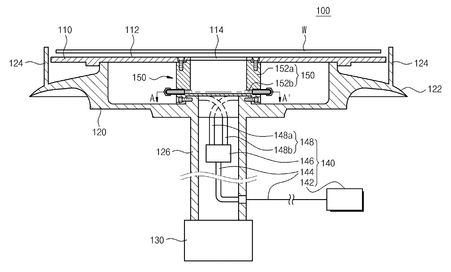
도 4는 도 2의 기판 지지유닛의 단면도이다.4 is a cross-sectional view of the substrate support unit of FIG. 2.
도 5는 도 4의 기판 지지유닛의 평면도이다.5 is a plan view of the substrate supporting unit of FIG. 4.
도 6은 도 4의 A-A'선을 따라 절단한 단면도로 선회류 발생부재의 일 예를 보여주는 도면이다.6 is a cross-sectional view taken along line AA ′ of FIG. 4, showing an example of a swirl flow generating member.
도 7 내지 도 11은 각각 선회류 발생부재의 다른 실시예들을 보여주는 도면들이다.7 to 11 are views showing other embodiments of the swirl flow generating member, respectively.
도 12 및 도 13은 도 4의 기판 지지유닛의 다른 실시예를 보여주는 도면이다.12 and 13 illustrate another embodiment of the substrate support unit of FIG. 4.
도 14 및 도 15는 도 4의 기판 지지유닛의 또 다른 실시예를 보여주는 도면이다.14 and 15 are views showing still another embodiment of the substrate support unit of FIG.
도 16은 기판 지지유닛의 또 다른 실시예를 보여주는 도면이다.16 is a view showing another embodiment of the substrate support unit.
도 17은 본 발명에 따른 기판 처리 장치의 공정 과정을 설명하기 위한 도면이다.17 is a view for explaining the process of the substrate processing apparatus according to the present invention.
도 18은 도 17의 C-C'선을 절단한 모습을 보여주는 도면이다.FIG. 18 is a diagram illustrating a cut line C-C ′ of FIG. 17.
도 19 및 도 20은 본 발명에 따른 선회류 공급부재가 선회류를 공급하는 모습을 보여주는 도면들이다.19 and 20 are views showing the swirl flow supply member to supply the swirl flow in accordance with the present invention.
도 21은 본 발명에 따른 선회류 발생체 내부에서 선회류가 발생되는 모습을 보여주는 도면이다.21 is a view showing a swirl flow generated inside the swirl flow generating body according to the present invention.
*도면의 주요 부분에 대한 부호 설명** Description of symbols on the main parts of the drawings *
1 : 기판 처리 장치1: substrate processing apparatus
10 : 공정처리부10: process processing unit
20 : 처리유체 공급부20: treatment fluid supply unit
100 : 기판 지지유닛100: substrate support unit
110 : 척 플레이트110: Chuck Plate
120 : 베이스120: base
130 : 구동부130: drive unit
140 : 기체 공급부재140: gas supply member
150 : 선회류 발생체150: swirl flow generator
160 : 보조부양수단160: auxiliary support means
170 : 보조회전수단170: auxiliary rotation means
본 발명은 기판을 처리하는 장치 및 방법에 관한 것으로, 보다 상세하게는 공정시 기판을 지지하는 유닛 및 상기 유닛을 구비하여 기판을 처리하는 장치 및 방법에 관한 것이다.The present invention relates to an apparatus and method for processing a substrate, and more particularly, to a unit for supporting a substrate during a process and an apparatus and method for processing a substrate having the unit.
일반적인 기판 처리 장치는 반도체 집적회로 칩의 제조를 위한 웨이퍼 및 평판 디스플레이의 제조를 위한 유리 기판 등의 기판을 처리하는 장치이다. 이들 장치는 공정시 기판 지지유닛에 기판을 안착시켜 공정을 수행한다. 일반적으로 기판 지지유닛은 공정시 기계적 클램프를 사용하여 기판을 지지하거나, 정전기력 또는 진공에 의한 흡착력을 이용하여 기판을 지지하고, 공정시 기판을 회전시킨다.A general substrate processing apparatus is a device for processing a substrate such as a wafer for manufacturing a semiconductor integrated circuit chip and a glass substrate for manufacturing a flat panel display. These devices perform the process by mounting the substrate on the substrate support unit during the process. In general, the substrate support unit supports the substrate by using a mechanical clamp in the process, or supports the substrate by using electrostatic force or adsorption force by vacuum, and rotates the substrate during the process.
기판 지지유닛은 보통 공정시 웨이퍼를 안착시키는 척 플레이트(chuck plate)와 공정시 웨이퍼가 척 플레이트 상으로부터 이탈되지 않도록 웨이퍼의 가장자리를 척킹하는 척킹핀(chucking pin)들을 구비한다.The substrate support unit usually includes a chuck plate that seats the wafer in the process and chucking pins that chuck the edge of the wafer so that the wafer does not escape from the chuck plate during the process.
그러나, 일반적인 기판 지지유닛은 웨이퍼를 척 플레이트에 안착시킨 후 웨이퍼를 기계적으로 고정시켜 공정을 진행하므로, 상기 고정 수단에 의해 기계적으로 접촉되는 부분에서 웨이퍼가 오염되거나 손상된다. 특히, 웨이퍼를 회전시켜 공정을 처리하는 장치들(예컨대, 스핀 세정 장치, 스핀 식각 장치, 감광액 도포 장치, 그리고 웨이퍼 베벨부 식각장치)에서는 웨이퍼를 상기 고정 수단에 의해 고정 시킨 후 회전시켜 공정을 수행하므로, 고정 수단과 접촉하는 웨이퍼 표면에서 오염 및 스크래치가 발생된다. 또한, 상기 장치들은 모터와 같은 기계적 어셈블리에 의해 기판을 회전하므로, 기계적인 구동에 따른 파티클 등의 오염물질이 발생된다. 이러한 오염물질들은 공정시 웨이퍼 및 장치를 오염시켜 공정 수율을 저하시킨다. 또한, 정전기력이나 진공에 의해 기판을 지지할 때 기판의 후면이 척 플레이트에 밀착되므로, 기판의 후면을 세정하거나 식각할 수 없다.However, the general substrate support unit proceeds by mounting the wafer on the chuck plate and then mechanically fixing the wafer so that the wafer is contaminated or damaged at the part that is mechanically contacted by the fixing means. In particular, in apparatuses that process a process by rotating a wafer (eg, a spin cleaning apparatus, a spin etching apparatus, a photoresist coating apparatus, and a wafer bevel portion etching apparatus), the wafer is fixed by the fixing means and then rotated to perform the process. Therefore, contamination and scratches occur on the wafer surface in contact with the fixing means. In addition, since the devices rotate the substrate by a mechanical assembly such as a motor, contaminants such as particles generated by mechanical driving are generated. These contaminants contaminate wafers and devices in the process, resulting in lower process yields. In addition, since the rear surface of the substrate is in close contact with the chuck plate when supporting the substrate by electrostatic force or vacuum, the rear surface of the substrate cannot be cleaned or etched.
본 발명은 공정시 기판 처리 효율을 향상시키는 기판 지지유닛, 그리고 이를 구비하는 기판 처리 장치 및 방법을 제공하는 것을 목적으로 한다.An object of the present invention is to provide a substrate support unit for improving substrate processing efficiency during processing, and a substrate processing apparatus and method having the same.
또한, 본 발명은 공정시 파티클의 발생을 방지하는 기판 지지유닛, 그리고 이를 구비하는 기판 처리 장치 및 방법을 제공하는 것을 목적으로 한다.In addition, an object of the present invention is to provide a substrate support unit for preventing the generation of particles during the process, and a substrate processing apparatus and method having the same.
또한, 본 발명은 공정시 기판이 손상되는 것을 방지하는 기판 지지유닛, 그리고 이를 구비하는 기판 처리 장치 및 방법을 제공하는 것을 목적으로 한다.In addition, an object of the present invention is to provide a substrate support unit for preventing the substrate from being damaged during the process, and a substrate processing apparatus and method having the same.
상술한 목적을 달성하기 위한 본 발명에 따른 기판 지지유닛은 척 플레이트 및 상기 척 플레이트로부터 기판이 부양되도록 상기 척 플레이트와 대향되는 기판면으로 선회류를 공급하는 선회류 공급부재를 포함한다.The substrate support unit according to the present invention for achieving the above object includes a chuck plate and a swirl flow supply member for supplying swirl flow to the substrate surface facing the chuck plate so that the substrate is supported from the chuck plate.
본 발명의 실시예에 따르면, 상기 선회류 공급부재는 상부가 개방된 통 형상의 선회류 발생체 및 상기 선회류 발생체 내부 공간에서 상기 선회류 발생체의 내측면을 따라 기체가 선회될 수 있도록 상기 선회류 발생체 내부로 상기 기체를 분 사시키는 기체 공급관을 포함한다.According to an embodiment of the present invention, the swirl flow supply member may have a cylindrical swirl swirl flow generator having an open upper portion and gas may be pivoted along an inner surface of the swirl flow generator in an inner space of the swirl flow generator. It includes a gas supply pipe for injecting the gas into the swirl flow generator.
본 발명의 실시예에 따르면, 상기 선회류 발생체는 상기 내부 공간이 원통형상을 가지며, 상기 기체 공급관은 상기 선회류 발생체의 내측면과 접선 방향으로 기체를 공급한다.According to an embodiment of the present invention, the swirl flow generating body has a cylindrical shape in the inner space, and the gas supply pipe supplies gas in a tangential direction with an inner surface of the swirl flow generating body.
본 발명의 일 실시예에 따르면, 상기 선회류 발생체는 상기 내부 공간이 원통형상을 가지며, 상기 선회류 발생체에는 상기 선회류 발생체의 내측면과 접선 방향으로 기체가 유입되도록 제공되는 기체 유입홀을 가진다.According to an embodiment of the present invention, the swirl flow generating body has an inner space having a cylindrical shape, and the swirl flow generating body has a gas inflow provided so that gas flows in a tangential direction with an inner surface of the swirl flow generating body. Have a hole
본 발명의 다른 실시예에 따르면, 상기 기체공급관은 상기 선회류 발생체의 내부에서 동일방향으로 회전되도록 상기 선회류 발생체에 연결되는 복수의 분사라인들을 포함한다.According to another embodiment of the present invention, the gas supply pipe includes a plurality of injection lines connected to the swirl flow generator to rotate in the same direction inside the swirl flow generator.
본 발명의 실시예에 따르면, 상기 기판 지지유닛은 공정시 기판이 상기 척 플레이트로부터 이탈되는 것을 방지하도록 상기 척 플레이트에 안착된 기판의 둘레에 제공되는 측면 가이드핀을 더 포함한다.According to an embodiment of the present invention, the substrate support unit further includes a side guide pin provided around the substrate seated on the chuck plate to prevent the substrate from being separated from the chuck plate during the process.
본 발명의 실시예에 따르면, 상기 선회류 발생체는 상기 척 플레이트의 중앙에 설치된다.According to an embodiment of the present invention, the swirl flow generating body is installed at the center of the chuck plate.
본 발명의 실시예에 따르면, 상기 기판 지지유닛은 상기 기체 공급관에 설치되어 상기 기체 공급라인으로 공급되는 기체의 양 조절하는 유량조절부재를 더 포함한다.According to an embodiment of the present invention, the substrate support unit further includes a flow rate adjusting member installed in the gas supply pipe to adjust the amount of gas supplied to the gas supply line.
본 발명의 다른 실시예에 따른 상기 기판 지지유닛은 공정시 상기 기판의 부양을 보조하는 보조부양수단을 더 포함하되, 상기 보조부양수단은 상기 척 플레이 트에 제공되며, 상기 기판의 저면으로 가스를 분사시키는 분사홀들 및 상기 분사홀들로 가스를 공급하는 가스 공급관을 포함한다.The substrate support unit according to another embodiment of the present invention further comprises an auxiliary support means for supporting the support of the substrate during the process, the auxiliary support means is provided to the chuck plate, the gas to the bottom of the substrate And a gas supply pipe for supplying gas to the injection holes and the injection holes.
본 발명의 다른 실시예에 따른 상기 선회류 발생체는 상기 척 플레이트의 중앙에 설치되며, 상기 분사홀들은 상기 선회류 발생체의 개방된 상부를 감싸도록 환형으로 배치된다.The swirl flow generating body according to another embodiment of the present invention is installed in the center of the chuck plate, the injection holes are arranged in an annular shape to surround the open upper portion of the swirl flow generating body.
본 발명의 또 다른 실시예에 따른 상기 기판 지지유닛은 공정시 상기 기판을 회전시키는 보조회전수단을 더 포함하되, 상기 보조회전수단은 공정시 상기 기판의 측면을 척킹하는 척킹핀들, 상기 척킹핀들이 설치되는 회전체, 그리고 상기 회전체를 회전시키는 구동모터를 포함한다.The substrate support unit according to another embodiment of the present invention further comprises an auxiliary rotation means for rotating the substrate during the process, the auxiliary rotation means chucking pins for chucking the side of the substrate during the process, the chucking pin And a drive motor for rotating the rotor.
본 발명의 또 다른 실시예에 따른 상기 회전체는 환형으로 제공된다.The rotating body according to another embodiment of the present invention is provided in an annular shape.
상술한 목적을 달성하기 위한 본 발명에 따른 기판 처리 장치는 내부에 공정을 수행하는 공간을 제공하는 컵, 상기 컵 내부에 배치되는 척 플레이트를 가지는 기판 지지유닛, 그리고 공정시 상기 척 플레이트와 대향되는 기판으로 처리유체를 공급하는 처리유체 공급부재를 포함하되, 상기 기판 지지유닛은 상기 척 플레이트로부터 기판이 부양되도록 상기 척 플레이트와 대향되는 기판면으로 선회류를 공급하는 선회류 공급부재를 포함한다.The substrate processing apparatus according to the present invention for achieving the above object is opposed to the chuck plate during the process, and a cup for providing a space for performing a process therein, a substrate support unit having a chuck plate disposed inside the cup And a processing fluid supply member for supplying a processing fluid to the substrate, wherein the substrate support unit includes a swirl flow supply member for supplying swirl flow to the substrate surface opposite the chuck plate so that the substrate is supported from the chuck plate.
본 발명의 실시예에 따르면, 상기 선회류 공급부재는 상부가 개방된 통 형상의 선회류 발생체 및 상기 선회류 발생체 내부 공간에서 상기 선회류 발생체의 내측면을 따라 기체가 선회될 수 있도록 상기 선회류 발생체 내부로 상기 기체를 분사시키는 기체 공급관을 포함한다.According to an embodiment of the present invention, the swirl flow supply member may have a cylindrical swirl swirl flow generator having an open upper portion and gas may be pivoted along an inner surface of the swirl flow generator in an inner space of the swirl flow generator. It includes a gas supply pipe for injecting the gas into the swirl flow generator.
본 발명의 실시예에 따르면, 상기 선회류 발생체는 상기 내부 공간이 원통형상을 가지며, 상기 기체 공급관은 상기 선회류 발생체의 내측면과 접선 방향으로 기체를 공급한다.According to an embodiment of the present invention, the swirl flow generating body has a cylindrical shape in the inner space, and the gas supply pipe supplies gas in a tangential direction with an inner surface of the swirl flow generating body.
본 발명의 일 실시예에 따르면, 상기 선회류 발생체는 상기 내부 공간이 원통형상을 가지며, 상기 선회류 발생체에는 상기 선회류 발생체의 내측면과 접선 방향으로 기체가 유입되도록 제공되는 기체 유입홀을 가진다.According to an embodiment of the present invention, the swirl flow generating body has an inner space having a cylindrical shape, and the swirl flow generating body has a gas inflow provided so that gas flows in a tangential direction with an inner surface of the swirl flow generating body. Have a hole
본 발명의 다른 실시예에 따르면, 상기 기체공급관은 상기 선회류 발생체의 내부에서 동일방향으로 회전되도록 상기 선회류 발생체에 연결되는 복수의 분사라인들을 포함한다.According to another embodiment of the present invention, the gas supply pipe includes a plurality of injection lines connected to the swirl flow generator to rotate in the same direction inside the swirl flow generator.
본 발명의 실시예에 따르면, 상기 기판 지지유닛은 공정시 기판이 상기 척 플레이트로부터 이탈되는 것을 방지하도록 상기 척 플레이트에 안착된 기판의 둘레에 제공되는 측면 가이드핀을 더 포함한다.According to an embodiment of the present invention, the substrate support unit further includes a side guide pin provided around the substrate seated on the chuck plate to prevent the substrate from being separated from the chuck plate during the process.
본 발명의 실시예에 따르면, 상기 선회류 발생체는 상기 척 플레이트의 중앙에 설치된다.According to an embodiment of the present invention, the swirl flow generating body is installed at the center of the chuck plate.
본 발명의 실시예에 따르면, 상기 기판 지지유닛은 상기 기체 공급관에 설치되어 상기 기체 공급라인으로 공급되는 기체의 양 조절하는 유량조절부재를 더 포함한다.According to an embodiment of the present invention, the substrate support unit further includes a flow rate adjusting member installed in the gas supply pipe to adjust the amount of gas supplied to the gas supply line.
본 발명의 다른 실시예에 따른 상기 기판 지지유닛은 공정시 상기 기판의 부양을 보조하는 보조부양수단을 더 포함하되, 상기 보조부양수단은 상기 척 플레이트에 제공되며, 상기 기판의 저면으로 가스를 분사시키는 분사홀들 및 상기 분사홀 들로 가스를 공급하는 가스 공급관을 포함한다.The substrate support unit according to another embodiment of the present invention further comprises an auxiliary support means for assisting the support of the substrate during the process, the auxiliary support means is provided on the chuck plate, and sprays gas to the bottom of the substrate And injection gas holes for supplying gas to the injection holes.
본 발명의 다른 실시예에 따른 상기 선회류 발생체는 상기 척 플레이트의 중앙에 설치되며, 상기 분사홀들은 상기 선회류 발생체의 개방된 상부를 감싸도록 환형으로 배치된다.The swirl flow generating body according to another embodiment of the present invention is installed in the center of the chuck plate, the injection holes are arranged in an annular shape to surround the open upper portion of the swirl flow generating body.
본 발명의 또 다른 실시예에 따른 상기 기판 지지유닛은 공정시 상기 기판을 회전시키는 보조회전수단을 더 포함하되, 상기 보조회전수단은 공정시 상기 기판의 측면을 척킹하는 척킹핀들, 상기 척킹핀들이 설치되는 회전체, 그리고 상기 회전체를 회전시키는 구동모터를 포함한다.The substrate support unit according to another embodiment of the present invention further comprises an auxiliary rotation means for rotating the substrate during the process, the auxiliary rotation means chucking pins for chucking the side of the substrate during the process, the chucking pin And a drive motor for rotating the rotor.
본 발명의 또 다른 실시예에 따른 상기 회전체는 환형으로 제공된다.The rotating body according to another embodiment of the present invention is provided in an annular shape.
상술한 목적을 달성하기 위한 본 발명에 따른 기판 처리 방법은 기판을 지지하여 공정을 수행하되, 상기 기판의 지지는 상기 기판의 저면으로 선회류를 공급하여 척 플레이트로부터 기판을 부양시켜 이루어진다.The substrate processing method according to the present invention for achieving the above object is to perform a process by supporting the substrate, the support of the substrate is made by supporting the substrate from the chuck plate by supplying a swirl flow to the bottom surface of the substrate.
본 발명의 실시예에 따르면, 상기 기판 처리 방법은 기판을 회전시켜 공정을 수행하되, 상기 기판의 회전은 상기 선회류에 의해 이루어지는 것을 포함한다.According to an embodiment of the present invention, the substrate processing method includes performing a process by rotating a substrate, wherein the rotation of the substrate is performed by the swirl flow.
본 발명의 실시예에 따르면, 상기 선회류는 상기 기판의 중앙으로 분사된다.According to an embodiment of the invention, the swirl flow is injected into the center of the substrate.
본 발명의 다른 실시예에 따르면, 상기 선회류는 상기 기판의 중앙으로 분사되고, 상기 기판 처리 방법은 공정시 상기 선회류에 의한 기판의 부양을 보조하도록 상기 기판으로 가스를 분사시키되, 상기 가스의 분사는 상기 선회류가 분사되는 부분을 감싸는 위치에서 이루어진다.According to another embodiment of the present invention, the swirl flow is injected into the center of the substrate, the substrate processing method is to inject a gas to the substrate to assist the support of the substrate by the swirl flow during the process, the Injection is performed at a position surrounding the portion where the swirl flow is injected.
본 발명의 또 다른 실시예에 따르면, 상기 기판 처리 방법은 공정시 상기 기 판의 측면과 접촉하여 상기 기판을 회전시키는 핀들을 사용하여 상기 선회류에 의한 기판의 회전을 보조한다.According to another embodiment of the present invention, the substrate processing method assists the rotation of the substrate by the swirl flow using pins that rotate the substrate in contact with the side of the substrate during the process.
본 발명의 또 다른 실시예에 따르면, 상기 기판의 회전은 기판의 공정속도가 기준속도 이하인 경우에는 상기 선회류를 공급하여 기판을 회전시키고, 기판의 공정속도가 기준속도 이상인 경우에는 회전모터를 사용하여 기판을 기계적으로 회전시키는 것을 더 포함한다.According to another embodiment of the present invention, the rotation of the substrate rotates the substrate by supplying the swirl flow when the process speed of the substrate is less than the reference speed, and uses a rotating motor when the process speed of the substrate is more than the reference speed Thereby mechanically rotating the substrate.
이하, 첨부한 도면들을 참조하여 본 발명의 바람직한 실시예를 상세히 설명하기로 한다. 그러나, 본 발명은 여기서 설명되어지는 실시예에 한정되지 않고 다른 형태로 구체화될 수 있다. 오히려, 여기서 소개되는 일 실시예는 개시된 내용이 철저하고 완전해지도록, 그리고 당업자에게 본 발명의 사상이 충분히 전달되도록 하기 위해 제공되는 것이다. 또한, 본 실시예에서는 반도체 웨이퍼를 습식으로 처리하는 반도체 제조 장치를 예로 들어 설명하였으나, 본 발명은 기판을 처리하는 모든 기판 처리 장치에 적용이 가능하다.Hereinafter, exemplary embodiments of the present invention will be described in detail with reference to the accompanying drawings. However, the invention is not limited to the embodiments described herein but may be embodied in other forms. Rather, one embodiment introduced herein is provided so that the disclosure will be thorough and complete, and will fully convey the spirit of the invention to those skilled in the art. In addition, in the present embodiment, a semiconductor manufacturing apparatus for wet processing a semiconductor wafer has been described as an example, but the present invention can be applied to all substrate processing apparatuses for processing a substrate.
(실시예)(Example)
도 1은 본 발명에 따른 기판 처리 장치의 사시도이고, 도 2는 도 1에 도시된 기판 처리 장치의 내부 구성을 보여주는 도면이다. 도 1 및 도 2를 참조하면, 본 발명에 따른 기판 처리 장치(apparatus for treating substrate)(1)는 공정처리부(process treating member)(10) 및 처리유체 공급부(treating-fluid supply member)(20)를 가진다. 공정처리부(10)는 매엽식으로 기판(이하, '웨이퍼'라 함)을 처리한다. 예컨대, 상기 기판 처리 공정은 웨이퍼 표면에 감광액을 도포하는 도포 공정, 웨이퍼 표면의 불필요한 이물질을 제거하는 식각 공정 및 세정 공정, 그리고 웨이퍼의 가장자리 영역을 식각하는 베벨 식각 공정 등 일수 있다. 1 is a perspective view of a substrate processing apparatus according to the present invention, Figure 2 is a view showing the internal configuration of the substrate processing apparatus shown in FIG. 1 and 2, an apparatus for treating
처리유체 공급부(20)는 공정에 필요한 처리유체를 공급한다. 처리유체로는 다양한 종류의 케미칼 및 유기용제, 그리고 처리가스가 사용될 수 있다. 예컨대, 처리유체는 감광액(photoresist), 식각액(etcher, stripper), 그리고 세정액(cleaning liquid) 등의 처리액 또는 불활성 가스, 건조가스 등의 처리가스 등 일 수 있다.The treatment
공정 처리부(10)는 컵(cup)(12) 및 기판 지지유닛(100)을 가진다. 컵(12)은 내부에 웨이퍼(W)를 처리하는 공정을 수행하는 공간을 제공한다. 컵(12)은 상부가 개방된 원통형상을 가진다. 컵(12)의 개방된 상부는 공정시 웨이퍼(W)가 상기 공간으로/으로부터 반입 및 반출되는 통로로 사용된다. 기판 지지유닛(100)은 공정시 컵(12) 내부에서 웨이퍼(W)를 지지 및 회전한다. 컵(12)의 하부에는 배수라인(12a)이 연결된다. 배수라인(12a)은 공정시 사용된 처리액을 배수한다.The
처리유체 공급부(20)는 노즐(22) 및 노즐 이송부재(24)를 가진다. 노즐(22)은 공정시 상술한 처리유체를 웨이퍼(W)로 분사한다. 노즐 이송부재(24)는 노즐(22)을 공정위치(a) 및 대기위치(b) 상호간에 이동시킨다. 공정위치(a)는 노즐(22)이 기판(W)의 처리면으로 처리유체를 분사하기 위한 위치이고, 대기위치(b)는 노즐(22)이 공정위치(a)로 이동되기 전에 컵(12)의 외부에서 대기하는 위치이다. 노즐 이송부재(24)는 제1 아암(24a) 및 제2 아암(24b), 그리고 구동기(24c)를 포함한다. 제1 및 제2 아암(24a, 24b)은 바(bar) 형상을 가진다. 제1 아암(24a)은 컵(12)의 상부에서 수평으로 설치되며, 제2 아암(24b)은 컵(12)의 측부에서 수직하게 설치된다. 제1 아암(24a)의 일단에는 노즐(22)이 결합되고, 제1 아암(24a)의 타단은 제2 아암(24b)과 서로 축결합된다. 그리고, 구동기(24c)는 제1 및 제2 아암(24a, 24b)을 유기적으로 동작시켜, 공정위치(a) 및 대기위치(b) 상호간에 노즐(22)을 이동시킨다.The treatment
본 실시예에서는 컵(12) 및 하나의 처리유체 공급부(20)를 구비하는 기판 처리 장치(1)를 예로 들어 설명하였으나, 기판 처리 장치(1)의 구성 및 구조는 다양하게 변경 및 변형이 가능하다. 예컨대, 도 3은 본 발명의 다른 실시예에 따른 기판 처리 장치(1')를 보여준다. 도 3의 기판 처리 장치(1')는 회수부재(14)를 더 구비하는 공정처리부(10) 및 복수의 처리유체 공급부(20a, 20b)를 가진다. 회수부재(14)는 공정시 사용되는 처리액을 회수한다. 회수부재(14)는 제1 회수통(14a) 및 제2 회수통(14b)을 포함한다. 제1 회수통(14a) 및 제2 회수통(14b)은 컵(12)의 내부에서 기판 지지유닛(100)를 감싸도록 환형으로 제공된다. 제1 회수통(14a) 내부에는 제1 처리액을 수용하는 공간(S1)이 제공되고, 제2 회수통(14b) 내부에서는 제2 처리액을 수용하는 공간(S2)이 제공된다. 제1 회수통(14a)에는 공정에 사용된 제1 처리액이 유입되는 개구(14a')가 형성되고, 제2 회수통(14b)에는 공정에 사용된 제2 처리액이 유입되는 개구(14b')가 형성된다. 각각의 개구(14b', 14a')는 상하로 위치된다. 그리고, 제1 회수통(14a)에는 공간(S1)에 수용된 제1 처리액을 회수하는 제1 회수라인(14a'')이 연결되고, 제2 회수통(14b)에는 공간(S2)에 수용된 제2 처리액을 회수하는 제2 회수라인(14b'')이 연결된다. 각각의 처리유체 공급부재(20a, 20b)는 상술한 처리유체 공급부재(20)와 동일한 구조를 가진다. 처리유체 공급부재(20a)는 제1 처리액을 분사하고, 처리유체 공급부재(20b)는 제2 처리액을 분사한다. 예컨대, 상기 제1 처리액으로는 웨이퍼(W) 표면에 잔류하는 이물질을 제거하는 세정액이 사용되고, 상기 제2 처리액으로는 웨이퍼(W) 표면에 잔류하는 세정액을 제거하는 린스액이 사용된다.In the present embodiment, the
상술한 구조의 기판 처리 장치(1')는 공정에 사용된 제1 처리액 및 제2 처리액을 분리회수한다. 즉, 공정시 처리유체 공급부재(20')가 분사한 제1 처리액은 기판 지지유닛(100)에 의해 회전되는 웨이퍼(W)의 원심력에 의해 웨이퍼(W)로부터 비산되어 제1 회수통(14a) 내 공간(S1)에 수용된다. 동일한 방식으로, 처리유체 공급부재(20'')가 분사한 제2 처리액은 제2 회수통(14b) 내 공간(S2)에 수용된다. 공정에 사용되는 제1 및 제2 처리액이 상기 공간(S1) 또는 공간(S2)으로 회수되도록, 기판 지지유닛(100)은 공정에 따라 개구(14a') 또는 개구(14b')에 대응되는 위치로 이동된다. 따라서, 사용된 제1 처리액 및 제2 처리액은 서로 독립적으로 회수된다. The
계속해서, 본 발명에 따른 기판 지지유닛(100)의 구성에 대해 상세히 설명한다. 도 4는 도 2의 기판 지지유닛의 단면도이고, 도 5는 도 4의 기판 지지유닛의 평면도이다. 그리고, 도 6은 도 4의 A-A'선을 따라 절단한 단면도로 선회류 발생부재의 일 예를 보여주는 도면이다.Subsequently, the configuration of the
도 4 내지 도 6을 참조하면, 기판 지지유닛(100)은 척 플레이트(chuck plate)(110), 베이스(base)(120), 구동부재(driving member)(130), 그리고 선회류 공급부재(swirl-flow supplying member)를 포함한다. 척 플레이트(110)는 대체로 원판현상을 가진다. 척 플레이트(110)는 공정시 웨이퍼(W)와 대향되는 상부면(112)을 가진다. 척 플레이트(110)의 중앙에는 개구(114)가 형성된다. 개구(114)는 공정시 선회류가 분사되는 홀이다. 4 to 6, the
베이스(120)는 척 플레이트(110)를 지지한다. 베이스(120)는 척 플레이트(110)의 하부에서 척 플레이트(110)와 결합된다. 베이스(120)는 척 플레이트(110)의 직경보다 큰 직경을 가지는 원판형상을 가진다. 베이스(120)의 가장자리는 베이스(120)의 중심으로부터 멀어질수록 하향 경사진다. 따라서, 공정시 베이스(120)로 떨어진 처리액은 베이스(120)의 가장자리에 형성된 경사면을 따라 흘러내린다. 베이스(120)에는 복수의 측면 가이드 핀들(124)이 제공된다. 측면 가이드 핀들(124)은 공정시 웨이퍼(W)가 척 플레이트(110)로부터 측방향으로 이탈되는 것을 방지한다. 측면 가이드 핀들(124)의 내측면(124a)은 웨이퍼(W)의 측면과 상응하도록 라운드(round) 처리된다. 이러한 측면 가이드 핀들(124)의 내측면(124a)은 공정시 웨이퍼(W)가 내측면(124a)에 접촉되더라도 웨이퍼(W)의 측면에 스크래치가 발생되는 것을 방지할 수 있다. 측면 가이드 핀들(124)은 공정시 웨이퍼(W)의 측면과 비접촉되도록, 웨이퍼(W)의 직경보다 넓게 배치된다. 따라서, 공정 진행시 웨이퍼(W)는 측면 가이드 핀들(124)과 비접촉되며, 웨이퍼(W)가 척 플레이트(110)의 기설정된 공정위치로부터 이탈되는 경우 웨이퍼(W)는 측면 가이드 핀들(124)에 의해 그 이동이 제한된다. 베이스(120)의 중앙 하부에는 지지축(126)이 결합된다. 지지축(126)은 베이스(120)를 지지하며, 컵(12)의 바닥면 중앙을 관통하도록 위치된다.
구동부재(130)는 척 플레이트(110) 및 베이스(120)를 상하로 승강 및 하강시킨다. 구동부재(130)는 베이스(120)의 지지축(126)과 결합된다. 구동부재(130)는 지지축(126)을 승강 및 하강시켜 척 플레이트(110)에 의해 지지된 웨이퍼(W)의 높이를 조절한다. 즉, 구동부재(130)는 웨이퍼(W)의 로딩(loading) 및 언로딩(unloading)시에는 척 플레이트(110)의 상부면이 컵(12)의 개방된 상부를 통해 컵(12) 외부에 노출되도록 척 플레이트(110)를 상승시키고, 웨이퍼(W)의 세정 처리시에는 상승된 척 플레이트(110)를 컵(12)의 내부로 하강시킨다.The driving
선회류 공급부재는 공정시 척 플레이트(110)와 마주보는 웨이퍼(W) 면으로 선회류를 공급한다. 선회류 공급부재는 기체 공급부재(gas supply member)(140) 및 선회류 발생체(swirl flow generating body)(150)를 포함한다. 기체 공급부재(140)는 공정시 선회류 발생체(150)로 기체를 공급한다. 기체 공급부재(140)는 기체 공급원(gas suuply source)(142) 및 기체 공급관(gas supply line)을 가진다. 기체 공급관은 메인 공급라인(main supply line)(144), 분배기(manifold)(146), 그리고 복수의 분사라인들(injection lines)(148)을 포함한다. 분사라인들(148)은 제1 분사라인(148a) 및 제2 분사라인(148b)을 가진다. 메인 공급라인(144)은 기체 공급원(142)으로부터 분배기(146)로 기체를 공급한다. 메인 공급라인(144)에는 유량 조절부재(미도시)가 설치된다. 유량조절부재는 메인 공급라인(144)을 통해 공급되는 기체의 유량을 조절한다. 유량조절부재로는 질량유량조절기(MFC:Mass Flowmeter Controller)가 사용될 수 있다. 분배기(146)는 공급받은 기체를 균등하게 분배하여 각각의 분사라인들(148a, 148b)로 공급한다. 분사라인들(148)은 분배기(146)에 의해 분배된 기체를 선회류 발생체(150)로 공급한다. 분사라인들(148)의 일단은 분배기(146)와 연결되고, 분사라인들(148)의 타단은 선회류 발생체(150)에 연결된다. 일 실시예로서, 각각의 분사라인(148a, 148b)의 타단은 선회류 발생체(150)의 측면 하부에 연결된다. 각각의 분사라인(148a, 148b)은 하우징(152)의 중심을 기준으로 하우징(152)의 측면을 따라 균등한 각도로 배치된다. 분사라인(148)은 후술할 선회류 발생체(150)의 기체 유입홀(152b)로 기체를 공급한다.The swirl flow supply member supplies swirl flow to the surface of the wafer W facing the
선회류 발생체(150)는 분사라인들(148)로부터 기체를 공급받아 선회류를 발생시킨다. 선회류 발생체(150)는 대체로 통 형상의 하우징(152)을 가진다. 하우징(152)은 척 플레이트(110)의 하부 중앙에 배치된다. 하우징(152)은 상부가 개방되며, 개방된 상부는 척 플레이트(110)의 개구(114)와 연결된다. 하우징(152)은 내부에 원통형상의 공간이 제공된다. 하우징(152)에는 기체 유입홀(152b)이 형성된다. 기체 유입홀(152b)은 분사라인들(148a, 148b)이 공급하는 기체를 하우징(152) 내부로 유입시킨다. 기체 유입홀(152b)은 분사라인들(148)이 공급하는 기체가 하우징(152)의 내측면(152a)의 접선방향으로 유입되도록 형성된다. 기체 유입홀(152b)은 하우징(152)의 중심을 기준으로 균등한 간격으로 제공된다. 기체 유입홀(152b)은 하우징(152)에 기체가 수평방향으로 공급되도록 형성된다. 또한, 기체 유입홀(152b)에는 분배라인(148)과 연결되기 위한 연결수단(154)이 제공된다. 연결수단(154)으로는 유니온(union), 커넥터(connecter) 등이 사용될 수 있다. 상술한 구조의 선회류 발생체(150)는 공정시 기체 공급부재(140)로부터 기체를 공급받아 선회류를 발생시킨다. 발생된 선회류는 기판(W)의 저면으로 분사되어 기판(W)을 척 플레이트(110)의 상부면(112)으로부터 부양시킨다. 또한, 부양된 기판(W)은 선회류에 의해 회전된다.The
본 실시예에서는 선회류 발생체(150)에 기체 유입홀(152b)이 제공되어 기체가 선회류 발생체(150) 내측면의 접선 방향으로 기체가 유입되도록 하는 것을 예로 들어 설명하였다. 그러나, 이와 달리 도 7에 도시된 바와 같이, 분사라인들(148a, 148b)이 직접 선회류 발생체(150)의 내측면까지 연장되어 선회류 발생체(150)의 내측면의 접선 방향으로 기체를 분사할 수 있다.In this embodiment, the
또한, 도 6에서는 두 개의 분사라인들(148a, 148b)로부터 기체를 공급받아 선회류를 발생시키는 선회류 공급부재를 예로 들어 설명하였으나, 선회류 공급부재로 기체를 공급하는 라인들의 개수는 1개 또는 3개 이상이 될 수 있다. 예컨대, 도 8을 참조하면, 본 발명의 다른 실시예에 따른 선회류 공급부재는 세 개의 분사라인들(148a, 148b, 148c)로부터 기체를 공급받아 선회류를 발생시킨다. 또는, 도 9를 참조하면, 본 발명의 또 다른 실시예에 따른 선회류 공급부재는 네 개의 분사라인들(148a, 148b, 148c, 148d)로부터 기체를 공급받아 선회류를 발생시킨다.In addition, in FIG. 6, the swirl flow supply member generating swirl flow by receiving gas from two
또한, 본 실시예에서는 분배라인(148) 및 기체 유입홀(152b)이 하우징(152)의 내부를 향해 수평으로 기체를 공급하는 것을 예로 들어 설명하였으나, 기체의 공급 각도는 다양하게 조절될 수 있다. 예컨대, 도 10을 참조하면, 본 발명의 또 실시예에 따른 선회류 공급부재(150c)는 선회류 발생체(150) 내부를 향해 상방향으로 기체가 공급되도록 분사라인(148) 및 기체 유입홀(152b)이 제공된다. 도 10의 선회류 발생체(150c)는 본 발명의 도 2의 선회류 발생체(150)에 비해 하우징(152) 으로 공급되는 기체가 보다 큰 상승기류를 가지는 선회류가 발생된다.In addition, in this embodiment, the
또한, 본 실시예에서는 선회류 발생체(150)가 원통형상의 내측면(152a)을 가지는 것을 예로 들어 설명하였으나, 선회류 발생체(150)의 하우징(152) 내측면(152a)의 형상은 다양하게 변경 및 변형이 가능하다. 또한, 도 11과 같이, 본 발명의 또 다른 실시예에 따른 선회류 발생체(150)의 내측면(152a)에는 나사산 형상의 홈(152a')이 제공될 수 있다.In addition, in the present embodiment, the
또한, 본 실시예에서는 하나의 선회류 발생체(150)가 척 플레이트(110)의 중앙에 배치되는 것을 예로 들어 설명하였다. 그러나, 선회류 발생체(150)는 배치 및 개수는 다양하게 변경될 수 있다. 예컨대, 도 12 및 도 13에 도시된 바와 같이, 기판 지지유닛(100a)은 네 개의 선회류 발생체(150)를 구비할 수 있다. 이때, 각각의 선회류 발생체(150)는 척 플레이트(110)의 중심으로부터 균등한 간격으로 배치된다.In addition, in the present embodiment, a single
또한, 본 실시예에서는 하나의 선회류 발생부재에 의해 공급되는 선회류만으로 웨이퍼(W)를 부양시키는 것을 예로 들어 설명하였으나, 기판 지지유닛에는 선회류에 의한 웨이퍼(W)의 부양을 보조하기 위한 수단이 더 제공될 수 있다. 예컨대, 도 14 및 도 15에 도시된 바와 같이, 기판 지지유닛(100b)에는 공정시 웨이퍼(W)의 저면을 향해 가스를 분사시키는 보조부양수단(160)이 제공된다. 보조부양수단(160)은 척 플레이트(110)에 형성되는 분사홀들(162) 및 상기 분사홀들(162)로 가스를 공급하는 가스 공급라인(164)을 포함한다. 분사홀들(162)은 척 플레이트(110) 중심을 기준으로 환형으로 배치된다. 이때, 분사홀들(162)은 척 플레이트(110)의 개 구(114)를 감싸도록 배치된다. 분사홀들(162)의 형상 및 크기는 다양하게 변화될 수 있다. 가스 공급라인(164)은 각각의 분사홀들(162)로 가스를 공급한다. 가스 공급라인(164)에 의해 분사홀들(162)로 공급된 가스는 웨이퍼(W)의 저면으로 분사되어 웨이퍼(W)를 부양시킨다. 따라서, 기판 지지유닛(100b)은 선회류 공급부재에 의한 웨이퍼(W)의 부양과 함께 가스분사부재(160)에 의한 웨이퍼(W)의 부양을 수행할 수 있어 보다 효과적으로 웨이퍼(W)를 부양시킬 수 있다.In the present embodiment, the wafer W is supported only by the swirl flow supplied by one swirl flow generating member. However, the substrate supporting unit supports the wafer W by swirl flow. Means may be further provided. For example, as shown in FIGS. 14 and 15, the
또한, 본 발명의 실시예에서는 선회류 발생부재에 의해 공급되는 선회류만으로 웨이퍼(W)를 회전시키는 것을 예로 들어 설명하였으나, 기판 지지유닛에는 선회류에 의한 웨이퍼(W)의 회전을 보조하기 위한 수단이 더 제공될 수 있다. 예컨대, 도 16을 참조하면, 기판 지지유닛(100c)은 회전보조수단(170)을 더 포함한다. 회전보조수단(170)은 회전체(rotating body)(172) 및 척킹핀들(chucking pins)(174)을 포함한다. 회전체(172)는 그 중심축을 기준으로 회전되도록 설치된다. 회전체(172)는 대체로 환형으로 제작되며, 베이스(120')를 감싸도록 설치된다. 회전체(172)의 중앙에는 회전축(172a)이 제공된다. 회전축(172a)은 베이스(120')의 지지축(126)을 중심으로 지지축(126)의 외부에서 회전가능하도록 설치된다. 회전축(172a)과 지지축(126) 사이에는 베어링들(bearing)(176)이 제공된다. 회전체(172)는 회전모터(미도시됨)에 의해 회전된다. 척킹핀들(174)은 회전체(172)의 가장자리에 설치된다. 척킹핀들(174)은 공정시 척 플레이트(110) 상에 지지되는 웨이퍼(W)의 가장자리 일부를 척킹한다. In addition, in the embodiment of the present invention has been described as an example of rotating the wafer (W) only by the swirl flow supplied by the swirl flow generating member, the substrate support unit for assisting the rotation of the wafer (W) by swirl flow Means may be further provided. For example, referring to FIG. 16, the
상술한 회전보조수단(170)은 공정시 회전모터를 이용하여 기계적으로 웨이 퍼(W)를 회전시킨다. 따라서, 기판 지지유닛(100c)은 선회류 공급부재에 의한 웨이퍼(W)의 회전 및 보조회전수단(170)에 의한 웨이퍼(W)의 회전을 함께 수행함으로써 보다 효과적으로 웨이퍼(W)를 회전시킬 수 있다. 특히, 이러한 구성의 기판 지지유닛(100c)은 공정시 선회류에 의한 웨이퍼(W)의 회전과 보조회전수단(170)에 의한 웨이퍼(W)의 회전을 선택적으로 수행할 수 있다. 즉, 웨이퍼(W)의 저속 회전이 요구되는 공정에서는 선회류 공급부재가 선회류를 공급함으로써 웨이퍼(W)의 회전시키고, 웨이퍼(W)의 고속 회전이 요구되는 공정에서는 보조회전수단(170)이 웨이퍼(W)를 회전시킨다. 예컨대, 일반적인 웨이퍼(W)의 세정공정에서는 세정액에 의한 웨이퍼(W)의 약액 세정 공정과 건조가스에 의한 웨이퍼(W)의 건조 공정이 연속적으로 처리된다. 이때, 건조 공정에서는 웨이퍼(W)가 고속으로 회전되고, 세정 공정에서는 웨이퍼(W)가 상대적으로 저속으로 회전된다. 따라서, 약액에 의한 세정공정에서는 선회류 공급부재에 의해 웨이퍼(W)를 회전시키고, 건조 공정에서는 보조회전수단(170)에 의해 웨이퍼(W)를 회전시킬 수 있다.The above-described rotational auxiliary means 170 mechanically rotates the wafer W using a rotating motor during the process. Therefore, the
이하, 본 발명에 따른 기판 처리 장치(1)의 공정 과정을 상세히 설명한다. 여기서, 상술한 구성들과 동일한 구성들에 참조번호는 동일하게 병기하고, 그 구성들에 대한 상세한 설명은 생략한다.Hereinafter, the process of the
도 17은 본 발명에 따른 기판 처리 장치의 공정 과정을 설명하기 위한 도면이고, 도 18은 도 17의 C-C'선을 절단한 도면이다. 그리고, 도 19는 본 발명에 따른 선회류 공급부재가 선회류를 공급하는 모습을 보여주는 도면이고, 도 20은 도 19의 D-D'선을 절단한 도면이다. 그리고, 도 21은 공정시 선회류 발생체의 내부 공 간을 보여주는 도면이다.17 is a view for explaining the process of the substrate processing apparatus according to the present invention, Figure 18 is a view taken along the line CC 'of FIG. 19 is a view showing a swirl flow supply member supplying swirl flow according to the present invention, and FIG. 20 is a view taken along line D-D ′ of FIG. 19. And, Figure 21 is a view showing the internal space of the swirl flow generating body during the process.
도 17 및 도 18을 참조하면, 공정이 개시되면, 웨이퍼(W)는 기판 지지유닛(100)의 척 플레이트(110) 상에 안착된다. 선회류 공급부재는 척 플레이트(110)에 형성된 개구(114)를 통해 척 플레이트(110)의 상부면(112)과 대향되는 웨이퍼(W)의 면으로 선회류를 공급한다. 즉, 도 19 및 도 20을 참조하면, 기체 공급관(140)은 선회류 발생체(150)로 기체를 공급한다. 이때, 유량조절부재는 메인 공급라인(144) 내부를 이동되는 기체가 기설정된 유량으로 공급되도록 미리 조절한다. 선회류 발생체(150)의 하우징(152) 내부로 분사되는 기체는 도 21에 도시된 바와 같이, 하우징(152)의 내측면(152a)을 따라 선회하면서 선회류가 발생된다. 발생된 선회류는 척 플레이트(110)의 개구(114)를 통해 분사되어 웨이퍼(W)의 중앙영역으로 공급된다. 17 and 18, when the process is started, the wafer W is seated on the
웨이퍼(W)로 공급된 선회류는 웨이퍼(W)를 척 플레이트(110)의 상부면(112)으로부터 부양시킨다. 이때, 부양된 웨이퍼(W)는 웨이퍼(W)의 저면과 척 플레이트(110)의 상부면(112) 사이 공간(c)을 빠져나가는 선회류에 의해 척 플레이트(110) 상부에서 지지된다. 즉, 공간(c)을 빠져나가는 선회류에 의해 공간(c) 내 압력이 강하되어 베르누이 효과(Bernouilli effect)에 의해 웨이퍼(W)는 척 플레이트(110) 상에서 고정 지지된다. 이때, 선회류는 웨이퍼(W)가 척 플레이트(110) 상에 안착되기 전에 공급되어 웨이퍼(W)가 척 플레이트(110)에 안착되기 전에 부양되도록 한다. 또는, 웨이퍼(W)은 척 플레이트(110)의 상부면(112)에 안착된 후 선회류에 의해 부양될 수도 있다.The swirl flow supplied to the wafer W lifts the wafer W from the
또한, 웨이퍼(W)는 공급된 선회류에 의해 기설정된 공정속도로 회전된다. 즉, 웨이퍼(W)의 중앙으로 공급된 선회류가 공간(c)의 중심으로부터 가장자리로 선회하면서 이동됨에 따라 웨이퍼(W)는 회전된다. 이때, 선회류 공급부재의 선회류 공급량에 따라 웨이퍼(W)의 회전속도는 조절된다. 즉, 선회류 공급부재의 유량조절부재는 메인 공급라인(144) 내 기체의 유량을 조절하여 웨이퍼(W)를 기설정된 회전속도로 조절한다. 이러한 유량조절부재의 유량 조절은 공정이 진행되기 전에 기설정된 유량만큼 기체가 공급되도록 셋팅값이 설정된다. 또는, 유량조절부재의 유량 조절은 공정 진행시 웨이퍼(W)의 회전속도를 실시간으로 감지하여 기설정된 회전속도를 만족하도록 메인 공급라인(144)의 내 기체의 유량을 조절할 수 있다.In addition, the wafer W is rotated at a predetermined process speed by the supplied swirl flow. That is, the wafer W is rotated as the swirl flow supplied to the center of the wafer W is moved while turning from the center of the space c to the edge. At this time, the rotational speed of the wafer W is adjusted according to the swirl flow supply amount of the swirl flow supply member. That is, the flow rate adjusting member of the swirl flow supply member adjusts the flow rate of the gas in the
웨이퍼(W)가 기설정된 공정속도로 회전되면, 처리유체 공급부재(20)는 회전되는 웨이퍼(W)의 처리면으로 처리액을 공급한다. 즉, 처리유체 공급부재(20)의 노즐 이송부재(24)는 노즐(22)을 대기위치(b)로부터 공정위치(a)로 이동시킨다. 노즐(22)이 공정위치(a)에 위치되면, 노즐(22)은 회전되는 웨이퍼(W)의 처리면으로 처리액을 공급한다. 공급된 처리액은 웨이퍼(W) 표면을 처리한 후 컵(12)의 배수라인(12a)을 통해 배수된다. 그리고, 공정이 완료된 웨이퍼(W)는 기판 지지유닛(100)으로부터 언로딩(unloading)된 후 컵(12) 외부로 반출된다.When the wafer W is rotated at a predetermined process speed, the processing
상술한 바와 같이, 본 발명에 따른 기판 지지유닛, 그리고 이를 구비하는 기판 처리 장치(1) 및 방법은 공정시 웨이퍼(W)로 선회류를 공급하여 웨이퍼(W)를 부양 및 회전시킨다. 본 발명은 공정시 웨이퍼(W)가 기판 지지유닛(100)의 척 플레이 트(110) 및 측면 가이드 핀들(124)과 같은 웨이퍼(W) 지지 수단과의 접촉없이 공정이 수행된다. 따라서, 본 발명은 종래의 공정시 웨이퍼(W)를 지지하기 위해 웨이퍼(W)와 접촉되는 수단에 의해 웨이퍼(W)가 손상되는 것을 방지한다.As described above, the substrate support unit according to the present invention, and the
또한, 본 발명은 공정시 기판(W)은 척 플레이트(110)로부터 부양시켜 회전시키므로, 척 플레이트(110)의 기판(W)면의 공정 수행이 가능하다. 예컨대, 부양된 기판(W)의 저면으로 처리가스 또는 처리액을 공급하여 기판(W)을 처리하는 것이 가능하다. In addition, in the present invention, since the substrate W is suspended from the
또한, 본 발명은 기판의 부양 및 회전을 위한 선회류의 공급량의 조절이 가능하다. 따라서, 공정시 공정 조건에 따라 선회류의 공급량을 변화시켜 웨이퍼(W)의 부양정도 및 웨이퍼(W)의 회전속도의 조절이 가능하다.In addition, the present invention is capable of adjusting the supply amount of swirl flow for the support and rotation of the substrate. Therefore, it is possible to adjust the degree of flotation of the wafer W and the rotational speed of the wafer W by changing the supply amount of the swirl flow in accordance with the process conditions during the process.
또한, 본 발명은 종래의 기판(W)을 고정 및 회전시키기 위한 장치들이 구비되지 않아 장치의 구조가 단순하여 제작 비용을 절감할 수 있다.In addition, the present invention is not equipped with a device for fixing and rotating the conventional substrate (W) can reduce the manufacturing cost of the simple structure of the device.
이상의 상세한 설명은 본 발명을 예시하는 것이다. 또한, 전술한 내용은 본 발명의 바람직한 실시 형태를 나타내고 설명하는 것이며, 본 발명은 다양한 다른 조합, 변경 및 환경에서 사용할 수 있다. 즉, 본 명세서에 개시된 발명의 개념의 범위, 저술한 개시 내용과 균등한 범위 및/또는 당업계의 기술 또는 지식의 범위 내에서 변경 또는 수정이 가능하다. 전술한 실시예는 본 발명의 기술적 사상을 구현하기 위한 최선의 상태를 설명하는 것이며, 본 발명과 같은 다른 발명을 이용하는데 당업계에 알려진 다른 상태로의 실시, 그리고 발명의 구체적인 적용 분야 및 용도에서 요구되는 다양한 변경도 가능하다. 따라서, 이상의 발명의 상세한 설명은 개시된 실시 상태로 본 발명을 제한하려는 의도가 아니다. 또한 첨부된 청구범위는 다른 실시 상태도 포함하는 것으로 해석되어야 한다.The foregoing detailed description illustrates the present invention. In addition, the foregoing description shows and describes preferred embodiments of the present invention, and the present invention can be used in various other combinations, modifications, and environments. That is, changes or modifications may be made within the scope of the concept of the invention disclosed in this specification, the scope equivalent to the disclosed contents, and / or the skill or knowledge in the art. The above-described embodiments illustrate the best state for implementing the technical idea of the present invention, the use of other inventions such as the present invention in other state known in the art, and the specific fields of application and uses of the invention. Various changes required are also possible. Accordingly, the detailed description of the invention is not intended to limit the invention to the disclosed embodiments. Also, the appended claims should be construed to include other embodiments.
본 발명에 의하면 공정 진행시 기판을 비접촉방식으로 지지 및 회전시킬 수 있어 기판의 손상을 방지한다.According to the present invention, the substrate can be supported and rotated in a non-contact manner during the process, thereby preventing damage to the substrate.
또한, 본 발명은 공정시 척 플레이트와 마주보는 기판의 면(저면)의 처리가 가능하다.In addition, the present invention is capable of processing the surface (bottom surface) of the substrate facing the chuck plate during the process.
또한, 본 발명은 장치의 구조가 단순하고, 장치의 제작 비용을 절감할 수 있다.In addition, the present invention is simple in the structure of the device, it is possible to reduce the manufacturing cost of the device.
Claims (30)
Priority Applications (5)
| Application Number | Priority Date | Filing Date | Title |
|---|---|---|---|
| KR1020060135283A KR100885180B1 (en) | 2006-12-27 | 2006-12-27 | Substrate support unit, and apparatus and method for treating substrate with the same |
| CN2007101990780A CN101211811B (en) | 2006-12-27 | 2007-12-12 | Substrate material support unit and substrate material processing apparatus and method using same |
| US12/004,504 US20080223412A1 (en) | 2006-12-27 | 2007-12-20 | Substrate support member and apparatus and method for treating substrate with the same |
| TW096150246A TWI378528B (en) | 2006-12-27 | 2007-12-26 | Substrate support member and apparatus and method for treating substrate with the same |
| JP2007334683A JP2008166792A (en) | 2006-12-27 | 2007-12-26 | Substrate support unit, and substrate processing apparatus equipped with the substrate support unit, and substrate processing method |
Applications Claiming Priority (1)
| Application Number | Priority Date | Filing Date | Title |
|---|---|---|---|
| KR1020060135283A KR100885180B1 (en) | 2006-12-27 | 2006-12-27 | Substrate support unit, and apparatus and method for treating substrate with the same |
Publications (2)
| Publication Number | Publication Date |
|---|---|
| KR20080060788A KR20080060788A (en) | 2008-07-02 |
| KR100885180B1 true KR100885180B1 (en) | 2009-02-23 |
Family
ID=39611711
Family Applications (1)
| Application Number | Title | Priority Date | Filing Date |
|---|---|---|---|
| KR1020060135283A KR100885180B1 (en) | 2006-12-27 | 2006-12-27 | Substrate support unit, and apparatus and method for treating substrate with the same |
Country Status (5)
| Country | Link |
|---|---|
| US (1) | US20080223412A1 (en) |
| JP (1) | JP2008166792A (en) |
| KR (1) | KR100885180B1 (en) |
| CN (1) | CN101211811B (en) |
| TW (1) | TWI378528B (en) |
Families Citing this family (14)
| Publication number | Priority date | Publication date | Assignee | Title |
|---|---|---|---|---|
| JP5096849B2 (en) * | 2007-09-13 | 2012-12-12 | 株式会社Sokudo | Substrate processing apparatus and substrate processing method |
| JP5655010B2 (en) * | 2009-02-11 | 2015-01-14 | アプライド マテリアルズ インコーポレイテッドApplied Materials,Incorporated | Method and apparatus for non-contact substrate processing |
| KR101849383B1 (en) * | 2010-06-08 | 2018-04-16 | 액셀리스 테크놀러지스, 인크. | Heated electrostatic chuck including mechanical clamp capability at high temperature |
| CN102062524B (en) * | 2010-11-22 | 2012-11-21 | 烟台睿创微纳技术有限公司 | Automatic drying equipment for MEMS (micro electro mechanical system) device wafer |
| KR101165360B1 (en) * | 2010-11-26 | 2012-07-12 | 주식회사 프로텍 | Adhesive stamping apparatus for die bonder |
| TWI500482B (en) * | 2011-03-24 | 2015-09-21 | Nat Univ Tsing Hua | Vacuum device by using centrifugal resources |
| CN103286086A (en) * | 2012-03-05 | 2013-09-11 | 无锡华润华晶微电子有限公司 | Wafer cleaning method and device |
| US9589818B2 (en) * | 2012-12-20 | 2017-03-07 | Lam Research Ag | Apparatus for liquid treatment of wafer shaped articles and liquid control ring for use in same |
| EP3078462A1 (en) * | 2013-12-03 | 2016-10-12 | Harmotec Co., Ltd. | Holding device, holding system, control method, and conveyance device |
| TWI556874B (en) * | 2014-02-26 | 2016-11-11 | 辛耘企業股份有限公司 | Hollow and buffering actuating device |
| TWI599406B (en) * | 2014-02-26 | 2017-09-21 | 辛耘企業股份有限公司 | Hollow and buffering actuating device |
| JP6116629B2 (en) * | 2015-08-11 | 2017-04-19 | 株式会社ハーモテック | Suction device |
| JP2022039487A (en) * | 2020-08-28 | 2022-03-10 | 株式会社荏原製作所 | Workpiece support device and workpiece support method |
| JP7179391B1 (en) * | 2022-07-07 | 2022-11-29 | 日本Wst合同会社 | Semiconductor processing equipment |
Citations (3)
| Publication number | Priority date | Publication date | Assignee | Title |
|---|---|---|---|---|
| JPH09148416A (en) * | 1995-11-27 | 1997-06-06 | Dainippon Screen Mfg Co Ltd | Substrate rotating and holding device and rotary substrate treating device |
| JP2002064130A (en) * | 2000-06-09 | 2002-02-28 | Harmotec Corp | Non-contact transfer device |
| KR20060059843A (en) * | 2004-11-29 | 2006-06-02 | 에스엠씨 가부시키 가이샤 | Non-contact transport apparatus |
Family Cites Families (10)
| Publication number | Priority date | Publication date | Assignee | Title |
|---|---|---|---|---|
| JPS58106543A (en) * | 1981-12-21 | 1983-06-24 | Konishiroku Photo Ind Co Ltd | Spinner coating device |
| US5226383A (en) * | 1992-03-12 | 1993-07-13 | Bell Communications Research, Inc. | Gas foil rotating substrate holder |
| US7217325B2 (en) * | 1999-01-22 | 2007-05-15 | Semitool, Inc. | System for processing a workpiece |
| US7451774B2 (en) * | 2000-06-26 | 2008-11-18 | Applied Materials, Inc. | Method and apparatus for wafer cleaning |
| US6797069B2 (en) * | 2002-04-08 | 2004-09-28 | Cree, Inc. | Gas driven planetary rotation apparatus and methods for forming silicon carbide layers |
| US20040094186A1 (en) * | 2002-11-19 | 2004-05-20 | Igor Ivanov | Method and apparatus for uniform treatment of objects in liquids |
| DE60231256D1 (en) * | 2002-12-10 | 2009-04-02 | E T C Epitaxial Technology Ct | susceptor system |
| JP4043444B2 (en) * | 2004-02-18 | 2008-02-06 | 東京エレクトロン株式会社 | Coating processing apparatus and coating processing method |
| US7938942B2 (en) * | 2004-03-12 | 2011-05-10 | Applied Materials, Inc. | Single side workpiece processing |
| JPWO2006051585A1 (en) * | 2004-11-10 | 2008-05-29 | 三益半導体工業株式会社 | Single wafer processing system |
-
2006
- 2006-12-27 KR KR1020060135283A patent/KR100885180B1/en active IP Right Grant
-
2007
- 2007-12-12 CN CN2007101990780A patent/CN101211811B/en active Active
- 2007-12-20 US US12/004,504 patent/US20080223412A1/en not_active Abandoned
- 2007-12-26 TW TW096150246A patent/TWI378528B/en active
- 2007-12-26 JP JP2007334683A patent/JP2008166792A/en active Pending
Patent Citations (3)
| Publication number | Priority date | Publication date | Assignee | Title |
|---|---|---|---|---|
| JPH09148416A (en) * | 1995-11-27 | 1997-06-06 | Dainippon Screen Mfg Co Ltd | Substrate rotating and holding device and rotary substrate treating device |
| JP2002064130A (en) * | 2000-06-09 | 2002-02-28 | Harmotec Corp | Non-contact transfer device |
| KR20060059843A (en) * | 2004-11-29 | 2006-06-02 | 에스엠씨 가부시키 가이샤 | Non-contact transport apparatus |
Also Published As
| Publication number | Publication date |
|---|---|
| US20080223412A1 (en) | 2008-09-18 |
| TW200847320A (en) | 2008-12-01 |
| CN101211811B (en) | 2011-05-11 |
| TWI378528B (en) | 2012-12-01 |
| CN101211811A (en) | 2008-07-02 |
| KR20080060788A (en) | 2008-07-02 |
| JP2008166792A (en) | 2008-07-17 |
Similar Documents
| Publication | Publication Date | Title |
|---|---|---|
| KR100885180B1 (en) | Substrate support unit, and apparatus and method for treating substrate with the same | |
| KR101017654B1 (en) | Substrate chucking member, substrate processing apparatus having the same and method of processing substrate using the same | |
| US7802579B2 (en) | Apparatus and method for treating substrates | |
| TWI458035B (en) | Substrate processing apparatus and substrate processing method | |
| JP4018958B2 (en) | Substrate processing equipment | |
| KR101325899B1 (en) | Liquid processing apparatus and liquid processing method | |
| TWI547765B (en) | Substrate processing method and substrate processing apparatus | |
| US20060081269A1 (en) | Method and apparatus for cleaning and drying wafers | |
| US20180272376A1 (en) | Substrate treatment apparatus | |
| CN106816399B (en) | Substrate processing apparatus and method | |
| US11145520B2 (en) | Method for treating substrate involving supplying treatment liquid to peripheral area of substrate by second nozzle | |
| US10331049B2 (en) | Substrate cleaning device and substrate processing apparatus including the same | |
| JP7438015B2 (en) | Substrate processing equipment | |
| US20090107522A1 (en) | Substrate treatment method and substrate treatment apparatus | |
| KR20090029407A (en) | Support member and apparatus for treating substrate with the same | |
| KR100862703B1 (en) | Support member, and apparatus and method for treating substrate with the same | |
| KR100834117B1 (en) | Substrate support unit, and apparatus and method for treating substrate with the same | |
| KR102201878B1 (en) | Chuck pin and apparatus for treating substrate comprising thereof | |
| JP2009105145A (en) | Substrate processing apparatus | |
| KR102550000B1 (en) | Spin chuck apparatus with improved substrate supporting function | |
| KR102583458B1 (en) | Unit for recycling treating liquid of substrate and apparatus for treating substrate with the unit | |
| KR102134432B1 (en) | Pipe cleaning jig, apparatus for processing substrate including the same, and cleaning method for pipe unit | |
| KR102180009B1 (en) | Apparatus and Method for treating substrate | |
| KR102289152B1 (en) | substrate processing apparatus and substrate processing method | |
| KR20200078792A (en) | Method and Apparatus for treating substrate |
Legal Events
| Date | Code | Title | Description |
|---|---|---|---|
| A201 | Request for examination | ||
| E902 | Notification of reason for refusal | ||
| E90F | Notification of reason for final refusal | ||
| E701 | Decision to grant or registration of patent right | ||
| GRNT | Written decision to grant | ||
| FPAY | Annual fee payment |
Payment date: 20130219 Year of fee payment: 5 |
|
| FPAY | Annual fee payment |
Payment date: 20140214 Year of fee payment: 6 |
|
| FPAY | Annual fee payment |
Payment date: 20150213 Year of fee payment: 7 |
|
| FPAY | Annual fee payment |
Payment date: 20160202 Year of fee payment: 8 |
|
| FPAY | Annual fee payment |
Payment date: 20170208 Year of fee payment: 9 |
|
| FPAY | Annual fee payment |
Payment date: 20180208 Year of fee payment: 10 |
|
| FPAY | Annual fee payment |
Payment date: 20200206 Year of fee payment: 12 |