KR100728262B1 - Diffusing sheet, surface light source apparatus, and rear projection display apparatus - Google Patents
Diffusing sheet, surface light source apparatus, and rear projection display apparatus Download PDFInfo
- Publication number
- KR100728262B1 KR100728262B1 KR1020050030763A KR20050030763A KR100728262B1 KR 100728262 B1 KR100728262 B1 KR 100728262B1 KR 1020050030763 A KR1020050030763 A KR 1020050030763A KR 20050030763 A KR20050030763 A KR 20050030763A KR 100728262 B1 KR100728262 B1 KR 100728262B1
- Authority
- KR
- South Korea
- Prior art keywords
- diffusion
- light source
- light
- sheet
- diffusion sheet
- Prior art date
Links
Images


Classifications
-
- G—PHYSICS
- G02—OPTICS
- G02B—OPTICAL ELEMENTS, SYSTEMS OR APPARATUS
- G02B3/00—Simple or compound lenses
- G02B3/02—Simple or compound lenses with non-spherical faces
- G02B3/04—Simple or compound lenses with non-spherical faces with continuous faces that are rotationally symmetrical but deviate from a true sphere, e.g. so called "aspheric" lenses
-
- B—PERFORMING OPERATIONS; TRANSPORTING
- B42—BOOKBINDING; ALBUMS; FILES; SPECIAL PRINTED MATTER
- B42F—SHEETS TEMPORARILY ATTACHED TOGETHER; FILING APPLIANCES; FILE CARDS; INDEXING
- B42F7/00—Filing appliances without fastening means
- B42F7/06—Filing appliances comprising a plurality of pockets or compartments, e.g. portfolios or cases with a plurality of compartments
- B42F7/065—Filing appliances comprising a plurality of pockets or compartments, e.g. portfolios or cases with a plurality of compartments made of transparent material
-
- B—PERFORMING OPERATIONS; TRANSPORTING
- B42—BOOKBINDING; ALBUMS; FILES; SPECIAL PRINTED MATTER
- B42D—BOOKS; BOOK COVERS; LOOSE LEAVES; PRINTED MATTER CHARACTERISED BY IDENTIFICATION OR SECURITY FEATURES; PRINTED MATTER OF SPECIAL FORMAT OR STYLE NOT OTHERWISE PROVIDED FOR; DEVICES FOR USE THEREWITH AND NOT OTHERWISE PROVIDED FOR; MOVABLE-STRIP WRITING OR READING APPARATUS
- B42D15/00—Printed matter of special format or style not otherwise provided for
- B42D15/0006—Paper provided with guiding marks, e.g. ruled, squared or scaled paper
-
- B—PERFORMING OPERATIONS; TRANSPORTING
- B42—BOOKBINDING; ALBUMS; FILES; SPECIAL PRINTED MATTER
- B42D—BOOKS; BOOK COVERS; LOOSE LEAVES; PRINTED MATTER CHARACTERISED BY IDENTIFICATION OR SECURITY FEATURES; PRINTED MATTER OF SPECIAL FORMAT OR STYLE NOT OTHERWISE PROVIDED FOR; DEVICES FOR USE THEREWITH AND NOT OTHERWISE PROVIDED FOR; MOVABLE-STRIP WRITING OR READING APPARATUS
- B42D15/00—Printed matter of special format or style not otherwise provided for
- B42D15/0073—Printed matter of special format or style not otherwise provided for characterised by shape or material of the sheets
- B42D15/008—Foldable or folded sheets
-
- G—PHYSICS
- G02—OPTICS
- G02B—OPTICAL ELEMENTS, SYSTEMS OR APPARATUS
- G02B19/00—Condensers, e.g. light collectors or similar non-imaging optics
- G02B19/0004—Condensers, e.g. light collectors or similar non-imaging optics characterised by the optical means employed
- G02B19/0028—Condensers, e.g. light collectors or similar non-imaging optics characterised by the optical means employed refractive and reflective surfaces, e.g. non-imaging catadioptric systems
-
- G—PHYSICS
- G02—OPTICS
- G02B—OPTICAL ELEMENTS, SYSTEMS OR APPARATUS
- G02B19/00—Condensers, e.g. light collectors or similar non-imaging optics
- G02B19/0033—Condensers, e.g. light collectors or similar non-imaging optics characterised by the use
- G02B19/0047—Condensers, e.g. light collectors or similar non-imaging optics characterised by the use for use with a light source
-
- G—PHYSICS
- G02—OPTICS
- G02B—OPTICAL ELEMENTS, SYSTEMS OR APPARATUS
- G02B3/00—Simple or compound lenses
- G02B3/0006—Arrays
- G02B3/0012—Arrays characterised by the manufacturing method
- G02B3/0031—Replication or moulding, e.g. hot embossing, UV-casting, injection moulding
-
- G—PHYSICS
- G02—OPTICS
- G02B—OPTICAL ELEMENTS, SYSTEMS OR APPARATUS
- G02B3/00—Simple or compound lenses
- G02B3/0006—Arrays
- G02B3/0037—Arrays characterized by the distribution or form of lenses
- G02B3/005—Arrays characterized by the distribution or form of lenses arranged along a single direction only, e.g. lenticular sheets
-
- G—PHYSICS
- G02—OPTICS
- G02B—OPTICAL ELEMENTS, SYSTEMS OR APPARATUS
- G02B3/00—Simple or compound lenses
- G02B3/0006—Arrays
- G02B3/0037—Arrays characterized by the distribution or form of lenses
- G02B3/0056—Arrays characterized by the distribution or form of lenses arranged along two different directions in a plane, e.g. honeycomb arrangement of lenses
-
- G—PHYSICS
- G02—OPTICS
- G02B—OPTICAL ELEMENTS, SYSTEMS OR APPARATUS
- G02B3/00—Simple or compound lenses
- G02B3/0006—Arrays
- G02B3/0037—Arrays characterized by the distribution or form of lenses
- G02B3/0062—Stacked lens arrays, i.e. refractive surfaces arranged in at least two planes, without structurally separate optical elements in-between
-
- G—PHYSICS
- G02—OPTICS
- G02B—OPTICAL ELEMENTS, SYSTEMS OR APPARATUS
- G02B3/00—Simple or compound lenses
- G02B3/02—Simple or compound lenses with non-spherical faces
- G02B3/08—Simple or compound lenses with non-spherical faces with discontinuous faces, e.g. Fresnel lens
-
- G—PHYSICS
- G02—OPTICS
- G02F—OPTICAL DEVICES OR ARRANGEMENTS FOR THE CONTROL OF LIGHT BY MODIFICATION OF THE OPTICAL PROPERTIES OF THE MEDIA OF THE ELEMENTS INVOLVED THEREIN; NON-LINEAR OPTICS; FREQUENCY-CHANGING OF LIGHT; OPTICAL LOGIC ELEMENTS; OPTICAL ANALOGUE/DIGITAL CONVERTERS
- G02F1/00—Devices or arrangements for the control of the intensity, colour, phase, polarisation or direction of light arriving from an independent light source, e.g. switching, gating or modulating; Non-linear optics
- G02F1/01—Devices or arrangements for the control of the intensity, colour, phase, polarisation or direction of light arriving from an independent light source, e.g. switching, gating or modulating; Non-linear optics for the control of the intensity, phase, polarisation or colour
- G02F1/13—Devices or arrangements for the control of the intensity, colour, phase, polarisation or direction of light arriving from an independent light source, e.g. switching, gating or modulating; Non-linear optics for the control of the intensity, phase, polarisation or colour based on liquid crystals, e.g. single liquid crystal display cells
- G02F1/133—Constructional arrangements; Operation of liquid crystal cells; Circuit arrangements
- G02F1/1333—Constructional arrangements; Manufacturing methods
- G02F1/1335—Structural association of cells with optical devices, e.g. polarisers or reflectors
- G02F1/1336—Illuminating devices
- G02F1/133602—Direct backlight
- G02F1/133606—Direct backlight including a specially adapted diffusing, scattering or light controlling members
- G02F1/133607—Direct backlight including a specially adapted diffusing, scattering or light controlling members the light controlling member including light directing or refracting elements, e.g. prisms or lenses
Abstract
본 발명은 화면을 관찰하는 위치에 관계 없이 얼룩이 없는 균일한 조명이 이루어질 수 있는 확산시트, 면광원장치 및 투과형 표시장치를 제공하기 위한 것이다. 투과형 표시장치(10)는, LCD 패널(11)과, LCD 패널(11)을 배면에서 조명하는 면광원장치(16)를 갖도록 되어 있다. 면광원장치(16)는, 병렬로 배열된 복수의 음극선관(13)을 갖고 있다. 면광원장치(16)의 음극선관(13)과 LCD 패널(11) 사이에는 확산시트(14) 및 수렴시트(12)가 설치되어 있다. 확산시트(14)에는 광이 출사하는 출사측에 확산렌즈 어레이(141)가 형성되어 있다. 확산렌즈 어레이(141)는 그 단면이 타원인 타원통의 일부에 상당하는 형상을 이루는 복수의 단위렌즈를 갖고 있다. 수렴시트(12)는, 음극선관(13)쪽에서 시트면을 따라 형성된 단면형상이 대략 사다리꼴인 복수의 단위렌즈(121)를 갖고 있다. 그에 따라, 면광원장치(16)의 음극선관(13)으로부터의 조명광을 확산시켜 균일한 조명을 실행함과 더불어, 조명광을 수렴시켜 백라이트로서의 광의 이용효율을 높일 수가 있게 된다. An object of the present invention is to provide a diffusion sheet, a surface light source device, and a transmissive display device in which uniform illumination without spots can be achieved regardless of the position at which the screen is observed. The transmissive display device 10 includes an LCD panel 11 and a surface light source device 16 that illuminates the LCD panel 11 from the back. The surface light source device 16 has a plurality of cathode ray tubes 13 arranged in parallel. A diffusion sheet 14 and a convergence sheet 12 are provided between the cathode ray tube 13 and the LCD panel 11 of the surface light source device 16. The diffusion sheet 14 has a diffusion lens array 141 formed on the emission side from which light is emitted. The diffusion lens array 141 has a plurality of unit lenses having a shape corresponding to a part of an elliptic cylinder whose cross section is an ellipse. The convergence sheet 12 has a plurality of unit lenses 121 having a substantially trapezoidal cross-sectional shape formed along the sheet surface on the cathode ray tube 13 side. As a result, the illumination light from the cathode ray tube 13 of the surface light source device 16 can be diffused to perform uniform illumination, and the illumination light can be converged to increase the utilization efficiency of light as a backlight.
Description
도 1은 본 발명의 제1실시예에 따른 투과형 표시장치를 나타낸 사시도,1 is a perspective view illustrating a transmissive display device according to a first embodiment of the present invention;
도 2는 도 1에 도시된 투과형 표시장치의 면광원장치에 포함되는 확산시트를 나타낸 사시도,FIG. 2 is a perspective view illustrating a diffusion sheet included in the surface light source device of the transmissive display device shown in FIG. 1;
도 3은 도 2에 도시된 확산시트를 III-III 선에 따라 절단한 확대단면도,3 is an enlarged cross-sectional view of the diffusion sheet shown in FIG. 2 taken along line III-III;
도 4는 도 2에 도시된 확산시트에 대해 입사각 O°로 입사된 광의 궤적을 나타낸 도면,4 is a view showing a trajectory of light incident at an incident angle of 0 ° with respect to the diffusion sheet shown in FIG. 2;
도 5는 도 2에 도시된 확산시트에 대해 입사각 20°로 입사된 광의 궤적을 나타낸 도면,5 is a view showing a trajectory of light incident at an incident angle of 20 ° with respect to the diffusion sheet shown in FIG. 2;
도 6는 도 2에 도시된 확산시트에 대해 입사각 40°로 입사된 광의 궤적을 나타낸 도면,6 is a view showing a trajectory of light incident at an incident angle of 40 ° with respect to the diffusion sheet shown in FIG. 2;
도 7은 도 2에 도시된 확산시트에 대해 입사각 60°로 입사된 광의 궤적을 나타낸 도면,7 is a view showing a trajectory of light incident at an incident angle of 60 ° with respect to the diffusion sheet shown in FIG. 2;
도 8은 도 1에 도시된 투과형 표시장치의 면광원장치에 포함되는 수렴시트를 나타낸 사시도,8 is a perspective view illustrating a convergence sheet included in the surface light source device of the transmissive display device shown in FIG. 1;
도 9는 도 8에 도시된 수렴시트를 IX-IX 선에 따라 절단한 확대단면도,9 is an enlarged cross-sectional view of the convergence sheet shown in FIG. 8 taken along line IX-IX;
도 10은 도 8에 도시된 수렴시트의 입사측 단위렌즈의 광학적 작용을 설명하기 위한 도면,10 is a view for explaining an optical action of the unit lens of the incident side of the convergence sheet shown in FIG.
도 11은 도 8에 도시된 수렴시트에 대해 입사각 10°로 평행광선이 입사되었을 때의 광선추적 시뮬레이션의 결과를 나타낸 도면,FIG. 11 is a view showing a result of ray tracing simulation when parallel light is incident at an incident angle of 10 ° with respect to the convergence sheet shown in FIG. 8; FIG.
도 12는 도 8에 도시된 수렴시트에 대해 입사각 30°로 평행광선이 입사되었을 때의 광선추적 시뮬레이션의 결과를 나타낸 도면,FIG. 12 is a view showing a result of ray tracing simulation when parallel light is incident at an incident angle of 30 ° with respect to the convergence sheet shown in FIG. 8; FIG.
도 13은 입사측 단위렌즈 사이에 평탄부가 설치되지 않은 수렴시트에 대해 입사각 10°로 평행광선이 입사했을 때의 광선추적 시뮬레이션의 결과를 나타낸 도면,FIG. 13 is a view showing a result of ray tracing simulation when parallel rays are incident at an incident angle of 10 ° with respect to a convergence sheet having no flat portion provided between incident side unit lenses; FIG.
도 14는 입사측 단위렌즈의 사이에 평탄부가 형성되어 있지 않는 수렴시트에 대해 입사각 30°로 평행광선이 입사했을 때의 광선추적 시뮬레이션의 결과를 나타낸 도면, FIG. 14 is a view showing a result of ray tracing simulation when parallel rays are incident at an incident angle of 30 ° with respect to a convergence sheet having no flat portion formed between incident side unit lenses; FIG.
도 15는 도 8에 도시된 수렴시트를 XV-XV 선에 따라 절단한 확대단면도,15 is an enlarged cross-sectional view of the convergence sheet shown in FIG. 8 taken along an XV-XV line;
도 16은 본 발명의 제1실시예에 따른 확산시트를 가진 면광원장치의 수평방향의 휘도분포를 다른 종류의 면광원장치와 비교해서 나타낸 도면,FIG. 16 is a view showing the luminance distribution in the horizontal direction of a surface light source device having a diffusion sheet according to the first embodiment of the present invention in comparison with other types of surface light source devices; FIG.
도 17은 본 발명의 제1실시예에 따른 확산시트를 가진 면광원장치의 수평방향의 휘도분포를 다른 종류의 면광원장치와 비교해서 나타낸 도면.Fig. 17 is a view showing the luminance distribution in the horizontal direction of a surface light source device having a diffusion sheet according to the first embodiment of the present invention in comparison with other types of surface light source devices.
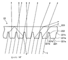
도 18은 본 발명의 제2실시예에 따른 투과형 표시장치의 면광원장치에 포함되는 수렴시트를 나타낸 확대단면도,18 is an enlarged cross-sectional view illustrating a converging sheet included in a surface light source device of a transmissive display device according to a second embodiment of the present invention;
도 19는 도 18에 도시된 수렴시트에 대해 입사각 10°로 평행광선이 입사했 을 때의 광선추적 시뮬레이션의 결과를 나타낸 도면,FIG. 19 is a view showing a result of ray tracing simulation when parallel light is incident at an incident angle of 10 ° with respect to the convergence sheet shown in FIG. 18. FIG.
도 20은 도 18에 도시된 수렴시트에 대해 입사각 30°로 평행광선이 입사했을 때의 광선추적 시뮬레이션의 결과를 나타낸 도면,20 is a view showing a result of ray tracing simulation when parallel light is incident at an incident angle of 30 ° with respect to the convergence sheet shown in FIG. 18;
도 21은 본 발명의 제2실시예에 따른 수렴시트를 가진 면광원장치의 휘도분포를 다른 종류의 면광원장치와 비교해서 나타낸 도면,FIG. 21 is a view showing the luminance distribution of the surface light source device having a converging sheet according to the second embodiment of the present invention in comparison with other types of surface light source devices; FIG.
도 22는 본 발명의 제3실시예에 따른 투과형 표시장치의 면광원장치에 포함되는 확산시트를 나타낸 확대단면도,FIG. 22 is an enlarged cross-sectional view illustrating a diffusion sheet included in a surface light source device of a transmissive display device according to a third exemplary embodiment of the present invention; FIG.
도 23은 도 22에 도시된 확산시트에 입사된 광의 궤적을 나타낸 도면,FIG. 23 is a view illustrating a trajectory of light incident on a diffusion sheet illustrated in FIG. 22;
도 24a 및 도 24b는 각각, 도 22에 도시된 확산시트의 확산렌즈 어레이의 형상이 특정한 식 (2)를 만족시키는 경우 및 특정의 식 (2)를 만족시키지 않는 경우에서의 광의 궤적을 나타낸 도면,24A and 24B are diagrams showing the trajectory of light when the shape of the diffusion lens array of the diffusion sheet shown in FIG. 22 satisfies the specific equation (2) and when the specific equation (2) is not satisfied. ,
도 25는 도 22에 도시된 확산시트에 관찰측에서 입사된 광의 궤적을 나타낸 도면,25 is a view showing a trajectory of light incident from an observation side to the diffusion sheet shown in FIG. 22;
도 26 a 및 도 26b는 도 22에 도시된 확산시트의 변형예를 나타낸 확대단면도,26A and 26B are enlarged cross-sectional views showing a modification of the diffusion sheet shown in FIG. 22;
도 27은 본 발명의 제4실시예에 따른 투과형 표시장치를 나타낸 사시도,27 is a perspective view of a transmissive display device according to a fourth embodiment of the present invention;
도 28a 및 도 28b는 본 발명의 제1 ~ 제4실시예에 따른 투과형 표시장치의 면광원장치에 포함되는 확산시트의 변형예를 나타낸 확대단면도,28A and 28B are enlarged cross-sectional views illustrating a modification of the diffusion sheet included in the surface light source device of the transmissive display device according to the first to fourth embodiments of the present invention;
도 28c 및 도 28d는 본 발명의 제1 및 제2실시예에 따른 투과형 표시장치의 면광원장치의 변형예를 나타낸 사시도,28C and 28D are perspective views illustrating modified examples of the surface light source device of the transmissive display device according to the first and second embodiments of the present invention;
도 29a 및 도 29b는 본 발명의 제1 ~ 제4실시예에 따른 확산시트를 구성하는 렌즈필름을 제조하는 방법을 설명하기 위한 모식도,29A and 29B are schematic views for explaining a method of manufacturing a lens film constituting a diffusion sheet according to the first to fourth embodiments of the present invention;
도 30a 및 도 30b는 도 29a 및 도 29b에 도시된 제조방법으로 제조된 렌즈필름을 기재층에 접착함으로써 렌즈필름과 기재층을 일체화시키는 방법을 설명하기 위한 도면,30A and 30B are views for explaining a method of integrating a lens film and a base layer by adhering a lens film manufactured by the manufacturing method shown in FIGS. 29A and 29B to a base layer;
도 31은 도 29a 및 도 29b에 도시된 제조방법으로 제조된 렌즈필름을 기재층의 형성시에 열라미네이트 함으로써, 렌즈필름과 기재층을 일체화시키는 방법을 설명하기 위한 도면이다.FIG. 31 is a view for explaining a method of integrating a lens film and a base layer by thermally laminating the lens film manufactured by the manufacturing method shown in FIGS. 29A and 29B when the base layer is formed.
본 발명은 액정표시장치등의 디스플레이 장치에 관한 것으로, 특히 투과형 액정표시장치 등을 배면에서 조명하는 면광원장치에 쓰이는 확산시트, 면광원장치 및 그들을 이용한 투과형 표시장치에 관한 것이다.BACKGROUND OF THE INVENTION 1. Field of the Invention The present invention relates to a display device such as a liquid crystal display device, and more particularly, to a diffusion sheet for use in a surface light source device for illuminating a transmissive liquid crystal display device or the like from the back, a surface light source device, and a transmissive display device using the same.
종래에도 투과형의 액정표시장치 등을 배면에서 조명하는 면광원장치로서, 각종 방식의 면광원장치가 제안되고 또 실용화되어 있다. 이와 같은 면광원장치는, 주로 면광원이 아닌 광원을 면광원으로 변환시키는 방식의 상위에 따라, 엣지라이트형과 직하형으로 나뉘어진다.Background Art Conventionally, various types of surface light source devices have been proposed and put into practical use as surface light source devices for illuminating transmissive liquid crystal displays and the like from the back. Such a surface light source device is mainly divided into an edge light type and a direct type according to the difference of the method of converting a light source which is not a surface light source into a surface light source.
그 중, 예컨대 직하형 면광원장치는, 병렬로 배열되는 음극선관에 의해 라이트 벌브(light bulb)로서 기능하는 LCD 패널 등의 투과형 표시부의 배면측에서 광 이 직접적으로 도입되도록 구성되어 있다. 그리고, 이와 같은 직하형 면광원장치에서, 음극선관과 투과형 표시부 사이에는 적당한 거리가 벌어져 그 사이에 확산판이 배치되고, 또 광을 수렴시키는 광학시트가 복수로 조합되어 배치되어 있다.Among them, for example, the direct type surface light source device is configured such that light is directly introduced from the back side of a transmissive display portion such as an LCD panel which functions as a light bulb by cathode ray tubes arranged in parallel. In such a direct type surface light source device, a suitable distance is provided between the cathode ray tube and the transmissive display portion, and a diffusion plate is disposed therebetween, and a plurality of optical sheets for converging light are arranged in combination.
그러나, 이와 같은 종래의 직하형의 면광원장치에서는, 필요로 하는 광학시트의 매수가 많은 비율로 광의 수렴특성이 불충분하다고 하는 문제가 있고, 이를 보충하기 위해 LCD 패널 등의 투과형 표시부 자체의 구조를 개량해서, 경사방향에서 입사되는 입사광에 대해서도 화질이 떨어지지 않도록 하고 있다. 그러나, 이와 같은 종래의 방식에서는 광의 이용효율이 저하되는 것 이외에도, LCD 패널 등의 투과형 표시부의 구성이 복잡해져 비용 증가의 요인으로 된다고 하는 문제가 있었다.However, such a conventional direct type surface light source device has a problem that the light convergence characteristic is insufficient at a large number of required optical sheets, and to compensate for this, the structure of a transmissive display unit such as an LCD panel is provided. In order to improve the quality, the incident light incident in the oblique direction is not deteriorated. However, such a conventional method has a problem that besides the decrease in the utilization efficiency of light, the configuration of a transmissive display unit such as an LCD panel is complicated, resulting in an increase in cost.
또, 종래의 직하형 면광원장치에서는, 음극선관에 근접한 부분인지 여부(즉, 음극선관에 지근의 위치인지, 병렬로 나란히 배열된 음극선관의 간극 부분에 지근한 위치인가)에 따라 광의 강도(휘도)에 얼룩이 발생하기 쉽다고 하는 문제가 있었다.In addition, in the conventional direct type surface light source device, the intensity of the light depends on whether the portion is close to the cathode ray tube (i.e., the position is close to the cathode ray tube, or is the position near the gap portion of the cathode ray tubes arranged in parallel). Luminance) is a problem that stains are likely to occur.
여기서, 앞에서 설명한 것과 같은 얼룩의 발생을 억제하기 위한 방법으로는, 음극선관과 LCD 패널 등의 투과형 표시부 사이의 간격을 크게 하는 방법이 고려될수 있으나, 이와 같은 방법에서는 디스플레이장치 전체의 두께가 두껍게 되버린다는 문제가 있었다.Herein, as a method for suppressing the occurrence of spots as described above, a method of increasing the distance between the cathode ray tube and the transmissive display portion such as an LCD panel may be considered, but in such a method, the entire thickness of the display apparatus becomes thick. Had a problem.
또, 앞에서 설명한 것과 같은 얼룩의 발생을 억제하기 위한 방법으로서, 음극선관과 LCD 패널 등의 투과형 표시부 사이에 배치된 광학시트 등에 의한 광의 확산의 정도를 강하게 하거나 광의 투과량을 제한하거나 하는 방법도 고려될 수 있으 나, 이와 같은 방법에서는 광의 사용량이 줄어든다고 하는 문제가 있었다.In addition, as a method for suppressing the occurrence of spots as described above, a method of increasing the degree of light diffusion or limiting the amount of light transmitted by an optical sheet or the like disposed between a cathode ray tube and a transmissive display such as an LCD panel may be considered. However, this method has a problem that the amount of light used is reduced.
보다 구체적으로는, 예컨대, 일본국 특허공개공보 평5-119703호 및 특허공개공보 평 11-242219호에, 면광원장치에서 라이팅 카텐이나 차광 도트층 등의 차광부분을 마련함으로써 광의 균일성을 유지하는 방법이 제안되어 있으나, 이와 같은 방법으로는 앞에서 설명한 방법과 마찬가지로 광의 사용량이 줄어든다고 하는 문제가 있었다.More specifically, for example, in Japanese Patent Application Laid-Open No. Hei 5-119703 and Japanese Patent Application Laid-Open No. Hei 11-242219, light uniformity such as a writing curtain or a shading dot layer is provided in a surface light source device to maintain uniformity of light. The method of the present invention has been proposed, but there is a problem that the amount of use of light decreases as in the above-described method.
또, 일본국 특허공개공보 평6-347612호에는, 면광원장치에서 양면에 렌티큐러렌즈를 설치한 시트에 의해 2방향의 확산제어를 실행하는 방법이 제안되어 있으나, 이 방법에서는 광을 수렴하기 위한 충분한 기능이 없고, 그 때문에 음극선관과의 위치관계에 따라 LCD 패널 등의 투과형 표시부의 면 내의 장소 마다 광축이 어긋나 여전히 화면을 관찰하는 위치에 따라 밝기의 얼룩이 발생한다고 하는 문제가 있었다.Further, Japanese Patent Laid-Open No. Hei 6-347612 proposes a method of performing two-way diffusion control by a sheet having a lenticular lens on both sides in a surface light source device, but in this method, light convergence is performed. There is not enough function for this, and accordingly, there existed a problem that an optical axis shifted in every place in the surface of a transmissive display part, such as an LCD panel, according to the positional relationship with a cathode ray tube, and the brightness unevenness arises according to the position which observes a screen.
본 발명은 이와 같은 점을 고려해서 발명된 것으로, 화면을 관찰하는 위치에 관계 없이 얼룩이 없는 균일한 조명이 이루어질 수 있는 확산시트, 면광원장치 및 투과형 표시장치를 제공하는 것을 목적으로 한다.The present invention has been invented in view of such a point, and an object of the present invention is to provide a diffusion sheet, a surface light source device, and a transmissive display device capable of achieving uniform illumination without spots regardless of the position of the screen.
본 발명은, 그 첫번째 해결수단으로서, 복수의 광원이 병렬로 배열된 광원부를 가진 직하형(直下型) 면광원장치에 조립되어 사용되고 상기 광원부의 각 광원으로부터 출사(出射)된 광을 확산시켜 균일화한 확산시트에서, 적어도 광이 출사하는 출사측에 형성된 확산렌즈 어레이로서, 상기 광원부의 상기 광원으로부터 출사된 광을 확산시켜 출사하는 복수의 단위렌즈를 가진 확산렌즈 어레이를 갖도록 한 것을 특징으로 한다.The present invention, as a first solution, is assembled and used in a direct type surface light source device having a light source portion arranged in parallel, a plurality of light sources are used to diffuse the light emitted from each light source to uniformize In one diffusion sheet, at least a diffusion lens array formed on an emission side from which light is emitted is provided so as to have a diffusion lens array having a plurality of unit lenses that diffuse and emit light emitted from the light source of the light source unit.
한편, 본 발명의 첫번째 해결수단에서, 상기 확산렌즈 어레이를 형성하는 단위렌즈는 그 단면이 타원인 타원통의 일부에 상당하는 형상 및 그 단면이 타원인 회전타원체의 일부에 상당하는 형상 중에서 선택된 적어도 1가지 형상을 하고, 상기 단면인 상기 타원의 장축이 시트면에 대해 직교하는 것이 바람직하다.On the other hand, in the first solution of the present invention, at least one unit lens forming the diffusion lens array is selected from a shape corresponding to a part of an elliptic cylinder whose cross section is an ellipse and a shape corresponding to a part of a rotary ellipsoid whose cross section is an ellipse. It is preferable to form one shape and the long axis of the said ellipse which is the said cross section orthogonal to a sheet surface.
또, 본 발명의 첫번째 해결수단에서, 상기 확산렌즈 어레이를 형성하는 상기 단위렌즈의 긴쪽 반경이 짧은쪽 반경의 1.5배 ~ 3배의 길이를 갖도록 하는 것이 바람직하다.In addition, in the first solution of the present invention, it is preferable that the long radius of the unit lens forming the diffusion lens array has a length of 1.5 to 3 times the short radius.
그리고, 본 발명의 첫번째 해결수단에서는, 상기 확산렌즈 어레이를 형성하는 상기 단위렌즈의 폭을 W, 높이를 H, 굴절률을 N로 하였을 때, arcsin(1/N) < arctan(1/((2H/W) - O.1))의 관계를 만족하도록 하는 것이 바람직하다.In the first solution of the present invention, arcsin (1 / N) < arctan (1 / ((2H) when the width of the unit lens forming the diffusion lens array is W, the height is H, and the refractive index is N. / W)-O.1)).
그리고, 본 발명의 첫번째 해결수단에서, 상기 확산렌즈 어레이를 형성하는 상기 각 단위렌즈 사이에는 평탄형상, 오목형상 및 미세요철형상 중 선택되는 적어도 1가지 형상을 이루는 부분이 형성되도록 하는 것이 바람직하다.In addition, in the first solution of the present invention, it is preferable that a portion forming at least one shape selected from among a flat shape, a concave shape, and a fine concave shape is formed between each unit lens forming the diffusion lens array.
또, 본 발명의 첫번째 해결수단에서, 확산시트 중 광이 입사되는 입사쪽에 광확산작용을 가진 미세요철형상을 이루는 입사면이 형성되어 있는 것이 바람직하다. 여기서, 상기 확산시트는 상기 입사면의 상기 미세요철형상에 의해 상기 확산렌즈 어레이에 의한 광확산작용에 더해, 1/2 확산각이 70°이내의 무지향성 광확산 작용을 갖도록 하는 것이 바람직하다. 한편, 본 명세서에서, 「 1/2 확산각 」이라 함은 밝기(휘도)의 값이 최대 밝기의 1/2로 되는 확산각을 말한다.Further, in the first solution of the present invention, it is preferable that an incidence surface forming a fine concave-convex shape having a light diffusing action is formed on the incidence side where light is incident in the diffusion sheet. Here, the diffusion sheet preferably has a non-directional light diffusion effect of less than 70 ° in addition to the light diffusion effect by the diffusion lens array due to the fine concave-convex shape of the incident surface. On the other hand, in this specification, "half-diffusion angle" means the diffusion angle at which the value of brightness (luminance) becomes 1/2 of the maximum brightness.
그리고, 본 발명의 첫번째 해결수단에서, 상기 확산시트는 그 적어도 일부에 광확산입자를 함유하는 것이 바람직하다. 여기서, 상기 확산시트는 상기 광확산입자에 의해, 상기 확산렌즈 어레이에 의한 광확산작용에 더해, 1/2 확산각이 70°이내의 무지향성 광확산작용을 가진 것이 바람직하다.In the first solution of the present invention, the diffusion sheet preferably contains light diffusing particles in at least a portion thereof. Here, it is preferable that the diffusion sheet has a non-directional light diffusion effect of less than 70 ° by the light diffusion particles in addition to the light diffusion action by the diffusion lens array.
그리고, 본 발명의 첫번째 해결수단에서, 상기 확산시트는 흡습율이 다른 2층 이상의 층을 갖고서, 이들 2층 이상의 층 중 광이 입사되는 입사측 층의 흡습율이 상기 확산렌즈 어레이가 형성된 상기 출사측 층의 흡습율보다 높은 것이 바람직하다.In the first solution of the present invention, the diffusion sheet has two or more layers having different moisture absorption rates, and the moisture absorption rate of the incident side layer to which light is incident among the two or more layers is the emission of the diffusion lens array. It is preferable that it is higher than the moisture absorption of a side layer.
본 발명은, 그 두번째 해결수단으로서, 투과형 표시부를 배면에서 조명하는 면광원장치에서, 복수의 광원이 병렬로 배열된 광원부와, 이 광원부의 각 광원에서 출사된 광을 확산시켜 균일화하는 확산시트로서, 앞에서 설명한 본 발명의 첫번째 해결수단에 따른 확산시트를 갖도록 된 것을 특징으로 한다.As a second solution, the present invention provides a surface light source device that illuminates a transmissive display portion from a back side, comprising: a light source portion in which a plurality of light sources are arranged in parallel, and a diffusion sheet for diffusing and uniformizing the light emitted from each light source of the light source portion. , Characterized in that it has a diffusion sheet according to the first solution of the present invention described above.
한편, 본 발명의 두번째 해결수단에서는, 상기 확산시트가 상기 광원부으로부터 광이 출사된 직후에 설치되어 있는 것이 바람직하다.On the other hand, in the second solution of the present invention, it is preferable that the diffusion sheet is provided immediately after the light is emitted from the light source portion.
본 발명은, 그 세번째 해결수단으로서, 투과형 표시부를 배면에서 조명하는 면광원장치에서, 복수의 광원이 병렬로 배열된 광원부와, 이 광원부의 각 광원에서 출사된 광을 확산시켜 균일화하는 확산시트부로서, 동일 또는 다른 종류의 적어도 2가지 확산시트를 가진 확산시트부를 갖고서, 상기 확산시트부의 각 확산시트가, 적어도 광이 출사하는 출사측에 형성된 확산렌즈 어레이로서, 상기 광원부의 각 광원에서 출사된 광을 확산시켜 출사하는 복수의 단위렌즈를 가진 확산렌즈 어레이를 갖도록 된 것을 특징으로 한다.As a third solution of the present invention, in a surface light source device for illuminating a transmissive display portion from a back side, a light source portion in which a plurality of light sources are arranged in parallel, and a diffusion sheet portion for diffusing and uniformizing the light emitted from each light source of the light source portion A diffusion lens array having at least two diffusion sheets of the same or different type, wherein each diffusion sheet of the diffusion sheet portion is formed on an emission side from which light exits, and is emitted from each light source of the light source portion; It is characterized in that it has a diffused lens array having a plurality of unit lenses for diffusing the light is emitted.
한편, 본 발명의 세번째 해결수단에서, 상기 확산시트부의 각 확산시트에 형성된 상기 확산렌즈 어레이를 형성하는 상기 단위렌즈가, 그 단면이 타원인 타원통의 일부에 상당하는 동일 또는 다른 종류의 형상을 하고서, 상기 단면인 상기 타원의 장축이 시트면에 대해 직교하도록 하는 것이 바람직하다.On the other hand, in the third solution of the present invention, the unit lens forming the diffuser lens array formed on each diffuser sheet of the diffuser sheet portion has the same or different type of shape that corresponds to a part of the elliptic cylinder whose cross section is an ellipse. Then, it is preferable that the major axis of the ellipse that is the cross section is orthogonal to the sheet surface.
또, 본 발명의 세번째 해결수단에서, 상기 확산시트부의 상기 적어도 2개의 확산시트가 각각의 확산렌즈 어레이에 의한 광확산작용 방향이 상호 직교하도록 배치되는 것이 바람직하다.Further, in the third solution of the present invention, it is preferable that the at least two diffusion sheets of the diffusion sheet portion are arranged such that the directions of light diffusion by each of the diffusion lens arrays are perpendicular to each other.
본 발명은, 그 네번째 해결수단으로서, 투과형 표시부와, 상기 투과형 표시부를 배면에서 조명하는 면광원장치로서, 앞에서 설명한 본 발명의 두번째 또는 세번째 해결수단에 따른 면광원장치를 갖도록 된 것을 특징으로 한다.The present invention is characterized in that, as a fourth solution, it has a transmissive display portion and a surface light source apparatus for illuminating the transmissive display portion from the back, and has a surface light source apparatus according to the second or third solution of the present invention described above.
(실시예)(Example)
이하, 도면을 참조해서 본 발명실시예에 대해 설명한다.EMBODIMENT OF THE INVENTION Hereinafter, embodiment of this invention is described with reference to drawings.
(제1실시예)(First embodiment)
먼저, 도 1 ~ 도 17를 가지고 본 발명의 제1실시예에 따른 투과형 표시장치에 대해 설명한다.First, the transmissive display device according to the first exemplary embodiment of the present invention will be described with reference to FIGS. 1 to 17.
도 1에 도시된 것과 같이, 본 발명의 제1실시예에 따른 투과형 표시장치(10)는 액정표시소자에 의해 광의 투과/불투과를 제어함으로써 영상정보를 표시하는 투과형의 액정표시장치로, LCD 패널(투과형 표시부; 11)과, 이 LCD 패널(11)을 배면에서 조명하는 면광원장치(16)를 갖도록 되어 있다. 여기서, 면광원장치(16)는 적어도 수렴시트(12)와 음극선관(13), 확산시트(14) 및 반사몰드 편광성 시트(15)를 갖고 있는 바, 영상정보에 대응한 영상패턴이 형성된 LCD 패널(11)에 대해 면광원장치(16)로 배면에서 광을 조사함으로써 LCD 패널(11) 상에 영상을 표시하도록 되어 있다. 한편, 도 1을 포함해서 이하의 각 도면은 어디까지나 구성을 모식적으로 나타낸 것으로, 각 부분의 크기나 형상 등은 이해를 쉽도록 하기 위해 적절히 과장해서 도시하였다.As shown in FIG. 1, the
이들 중 LCD 패널은 이른바 투과형 액정표시소자로 형성된 라이트 벌브이다. 한편, 본 발명의 제1실시예에서 LCD 패널은 30인치 사이즈로, 800 x 600 도트의 표시를 할 수 있도록 구성되어 있다.Among them, the LCD panel is a light bulb formed of a so-called transmissive liquid crystal display element. Meanwhile, in the first embodiment of the present invention, the LCD panel has a size of 30 inches and is configured to display 800 x 600 dots.
면광원장치(16)는 복수의 음극선관(13)이 병렬로 배열된 직하형 면광원장치이다. 음극선관(13)은, 백라이트(back light)로서의 광원부를 구성하는 선광원(線光源)이고, 본 발명의 제1실시예에서는, 대략 75mm 간격으로 등간격으로 6개가 병렬로 배열되어 있다. 또, 본 발명의 제1실시예에서는, 이와 같이 해서 배열되는 음극선관(13)이, 도 1에 도시된 것과 같이, 그 길이방향이 LCD 패널(11)의 수평방향을 따르는 방향으로 되고, 그 배열된 방향이 LCD 패널(11)에 대해 수직방향으로 되도록 배치되어 있다.The surface
여기서, 음극선관(13)의 배면에는 도시되지 않은 반사판이 설치되어 있는 바, 이와 같은 설계로 LCD 패널(11)의 화면의 각부위로 입사되는 광의 조도(照度)를 균일에 가까워지도록 하고 있다.Here, a reflecting plate (not shown) is provided on the rear surface of the
또, 음극선관(13)과 수렴시트(12) 사이에는 확산시트(14)가 설치되어 있다. 이와 같은 확산시트(14)가 설치됨으로써, 음극선관(13)에 근접한 부분인지 여부(즉, 음극선관(13)에 지근한 위치인지, 병렬로 나란히 배열된 음극선관(13)의 간극부분에 지근한 위치인지)에 따라 발생하는 화면상에서의 휘도의 얼룩이 대부분 해소된 상태로 되고, 그 상태에서 광이 수렴시트(12)에 도달하게 된다.In addition, a
여기서, 상기 확산시트(14)는 광원부를 구성하는 음극선관(13)에서 광이 출사된 직후에 설치되어 있는 것이 바람직하다. 이와 같이 배치함으로써, 화면상의 위치에 의하지 않고 얼룩이 없는 균일한 조명을 이룰 수 있음과 더불어, 광을 유효하게 이용해서 전체적으로 휘도를 향상시킬 수가 있게 된다.Here, the
다음에는, 면광원장치(16)에 조립되어 쓰이는 확산시트(14)에 대해 상세히 설명한다.Next, the
도 1 및 도 2에 도시된 것과 같이, 확산시트(14)는 음극선관(13)에서 출사된 광을 확산시켜 균일화하는 시트로서, 광이 출사하는 출사측에 확산렌즈 어레이(141)가 형성되어 있다.As shown in FIGS. 1 and 2, the
여기서, 상기 확산렌즈 어레이(141)는 음극선관(13)에서 출사된 광을 확산시켜 출사하는 것으로, 그 단면이 타원인 연속하는 타원통의 일부에 상당하는 형상을 한 복수의 단위렌즈를 갖도록 되어 있다. 한편, 이들 단위렌즈는 상호 평행하도록 다수가 배열되어 있는 바, 배열방향이 음극선관(13)의 배열방향과 일치하도록 되어 있다(도 1 참조). 또, 이들 단위렌즈는 전체적으로 렌티큐러렌즈를 구성하도록 되어 있다.The
여기서, 상기 확산렌즈 어레이(141)를 형성하는 각 단위렌즈는, 도 3에 도시된 것과 같이 그 단면이 타원으로 되어 있는 바, 그 타원의 장축(Xa)이 시트면에 대해 직교하도록 되어 있다. 바람직하기로는, 타원의 긴쪽 반경이 짧은쪽 반경의 1. 5배 ~ 3배의 길이로 되는 것이 좋다. 그에 따라, 음극선관(13)에 근접한 부분인지 여부에 따라 발생하는 화면상에서의 휘도의 얼룩이 효과적으로 방지될 수 있게 된다. 한편, 본 발명의 제1실시예에서는, 도 3에 예시되어 있듯이, 확산시트(14)의 두께가 2mm이고, 또 확산시트(14)의 확산렌즈 어레이(141)를 형성하는 각 단위렌즈의 단면이, 긴쪽 반경이 O.12mm, 짧은쪽 반경이 O.06 mm의 타원(그 장축이 확산시트(14)의 시트면에 대해 직교하는 타원)의 일부에 상당하는 형상으로 되고, 또 각 단위렌즈가 피치 O.1 mm로 되도록 배치되어 있다. 이 경우에는, 긴쪽 반경과 짧은쪽 반경의 비의 값(긴쪽 반경/짧은쪽 반경)이 2배가 되도록 되어 있다.Here, as shown in Fig. 3, each unit lens forming the
여기서, 확산렌즈 어레이(141)를 형성하는 각 단위렌즈의 단면인 타원의 긴쪽 반경과 짧은쪽 반경과의 비(긴쪽 반경/짧은쪽 반경)의 바람직한 범위(1. 5 ~3배)는 다음과 같이 해서 실험적으로 얻어지게 된다.Here, a preferable range (1.5-5 times) of the ratio (long radius / short radius) of the long radius and the short radius of the ellipse which is the cross section of each unit lens which forms the diffuse
즉, 각 단위렌즈의 단면인 타원의 긴쪽 반경과 짧은쪽 반경과의 비의 값이 다른 5가지 종류의 확산렌즈 어레이가 각각 형성된 5개의 확산시트를 준비한다. 그리고, 도 1에 도시된 구성의 면광원장치(16)에서, 확산시트(14)로 각각의 확산시트를 이용하고서 휘도의 얼룩의 발생상황을 관찰하고, 각 단위렌즈의 단면인 타원의 긴쪽 반경과 짧은쪽 반경과의 비(긴쪽 반경/짧은쪽 반경)를 변경시킨 경우의 휘도 의 얼룩의 발생상황을 비교한다. 그 결과를 표 1에 나타낸다.That is, five diffusion sheets each having five types of diffusion lens arrays having different ratios between the long radius and the short radius of an ellipse, which are sections of each unit lens, are prepared. In the surface
한편 여기서는, 도 1에 도시된 구성의 면광원장치(16)에서는, 수렴시트(12)가 있어서 얼룩의 발생을 확인하기 어렵기 때문에, 수렴시트(12)는 생략하고 확산시트(14)와 반사형 편광성시트(15)를 겹쳐 관찰한 형태와, 이들 사이에 새롭게 다른 확산판을 추가한 형태에 대해 실험을 실시하였다. 한편, 여기서 새롭게 추가한 확산판은 투과율 60%의 유백색 확산판으로서, 확산시트(14)와 반사형 편광성 시트(15) 사이에 배치한다. 한편, 아래 표 1에서, 원형 표시(0)는 얼룩이 발생하고 있지 않은 경우를 나타내고, 삼각표시(△)는 겨우 얼룩의 발생이 확인될 수 있는 경우를 나타내고, 가위표시(X)는 확실하게 얼룩이 발생되어 있는 경우를 나타낸다.On the other hand, in the surface
상기 표 1에서 알 수 있듯이, 확산렌즈 어레이(141)를 형성하는 각 단위렌즈의 단면인 타원의 긴쪽 반경과 짧은쪽 반경의 비(긴쪽 반경/짧은쪽 반경)의 값으로는, 2배가 되는 것이 얼룩을 막기 위해서 가장 적합하고, 다른 확산요소(유자확산판)를 가한 경우에는 1.5 ~ 3배의 범위에서 얼룩을 막을 수가 있다.As can be seen from Table 1, the value of the ratio (long radius / short radius) of the long radius and the short radius of the ellipse, which is the cross section of each unit lens forming the
한편, 확산렌즈 어레이(141)를 형성하는 각 단위렌즈의 단면인 타원의 긴쪽 반경과 짧은쪽 반경과의 비(긴쪽 반경/짧은쪽 반경)가 작으면(1배 등) 음극선관(13)에 가까운 위치가 밝아지고, 비가 크게 되면(5배 등) 병렬로 배열된 음극선관(13)의 간극부분에 가까운 위치가 밝아지는 경향이 있다.On the other hand, if the ratio (long radius / short radius) of the long radius and the short radius of the ellipse which is the cross section of each unit lens which forms the diffuse
한편, 도 3에 예시된 본 발명의 제1실시예에 따른 확산시트(14)에서는, 확산렌즈 어레이(141)를 형성하는 각 단위렌즈의 단면인 타원의 짧은쪽 반경에 대한 피치의 비(피치/짧은쪽 반경)의 값은 O.1/0.06 = 1.67 이다. 그러나, 이 피치의 비(피치/짧은쪽 반경)가 너무 작으면(짧은쪽 반경이 너무 크면) 각 단위렌즈의 렌즈표면의 형상이 평면에 가깝게 되어버려, 확산렌즈 어레이(141)의 렌즈효과를 충분히 얻을 수 없게 된다. 이에 대해, 이 피치의 비(피치/짧은쪽 반경)가 너무 크면(짧은쪽 반경이 너무 작으면) 확산렌즈 어레이(141)를 성형하기 위한 금형의 표면형상의 선단부가 너무 날카로워져 버린다. 그 때문에, 이 피치의 비(피치/짧은쪽 반경)는 O.5 ~ 1.8 정도인 것이 바람직하다.On the other hand, in the
다음에는 도 4 ~ 도 7에 의해 이와 같이 구성된 확산시트(14)의 광학적 작용에 대해 설명한다.Next, the optical action of the
도 4는 확산시트(14)에 대해 입사각 0°로 입사된 광의 궤적을 나타낸 도면이다. 도 4에 도시된 것과 같이, 이 경우에는, 입사각 0°로 광원쪽에서 입사된 광(L; 도 4에서는 11가닥의 광선으로 나타나 있음) 중 일부(도 4에서는 5가닥의 광선)가 관찰측으로 출사되고, 나머지(도 4에서는 6가닥의 광선)는 광원 쪽으로 되돌려지게 된다.4 is a view showing the trajectory of light incident on the
도 5는 확산시트(14)에 대해 입사각 20°로 입사된 광의 궤적을 나타낸 도면이다. 도 5에 도시된 것과 같이, 이 경우에는 입사각 20°로 광원 쪽에서 입사된 광(L; 도 5에서는 11가닥의 광선으로 나타나 있음) 중 일부(도 5에서는 6가닥의 광선)가 관찰측으로 출사되고, 나머지(도 5에서는 5가닥의 광선)가 광원 쪽으로 되돌려지게 된다.5 is a view showing the trajectory of light incident on the
도 6은 확산시트(14)에 대해 입사각 40°로 입사된 광의 궤적을 나타낸 도면이다. 도 6에 도시된 것과 같이, 이 경우에는, 입사각 40°로 광원 쪽에서 입사된 광(L; 도 6에서는 11가닥의 광선으로 나타나 있음) 중 일부(도 6에서는 8가닥의 광선)가 관찰측으로 출사되고, 나머지(도 6에서는 3가닥의 광선)는 광원 쪽으로 되돌려지게 된다.6 is a view showing the trajectory of the light incident on the
도 7은 확산시트(14)에 대해 입사각 60°로 입사된 광의 궤적을 나타낸 도면이다. 도 7에 도시된 것과 같이, 이 경우에는 입사각 60°로 광원 쪽에서 입사된 광(L; 도 7에서는 11가닥의 광선으로 나타나 있음) 중 일부(도 7에서는 10가닥의 광선)가 관찰측으로 출사되고, 나머지(도 7에서는 1가닥의 광선)은 광원 쪽으로 되돌려지게 된다.FIG. 7 is a view showing a trajectory of light incident on the
이들 도 4 ~ 도 7에서 알 수 있듯이, 확산시트(14)에 대해 작은 입사각도로 입사되는 광은, 그 중 많은 광이 광원 쪽으로 되돌려지고, 큰 입사각도로 입사되는 광은 광원 쪽으로 되돌려지는 일 없이 관찰측으로 출사된다. 확산시트(14)가 이와 같은 광학적 작용을 갖고 있기 때문에, 음극선관(13)이 출사된 조명광으로서 확산시트(14)를 통과하는 조명광은, 음극선관(13)에 근접한 위치에서는 입사각도가 작기 때문에 광원인 음극선관(13) 쪽으로 되돌려지는 비율이 많아지는 한편, 음극선관(13)에서 멀어짐(병렬로 배열된 음극선관(13)의 간극부분에 가깝게)에 따라 관찰측으로 출사되는 비율이 많아진다. 그 때문에, 확산시트(14)에서 최종적으로 출사되는 조명광은 그 조도가 균일화될 수 있게 된다.As can be seen from FIGS. 4 to 7, light incident at a small incident angle to the
다음에는, 이와 같이 구성된 확산시트(14)의 제조방법에 대해 설명한다. Next, the manufacturing method of the
확산시트(14)를 제조할 때에는, 먼저 확산렌즈 어레이(141)의 형상이 형성된 렌즈필름(141a)을 만든다.When manufacturing the
도 29a 및 도 29b는 렌즈필름(141a)의 2가지 제조공정을 설명하기 위한 도면이다. 한편, 도 29a 및 도 29b에서는, 이해를 쉽게 하기 위해 금형(301, 304)에 의해 형성된 렌즈필름(141a)의 각 단위렌즈의 길이방향이 금형(301, 304)의 회전중심에 따른 방향인 경우를 예로 들었으나, 렌즈필름(141a)의 각 단위렌즈의 길이방향은 금형(301, 304)의 회전원주를 따른 방향이어도 좋다. 한편, 후자의 경우가 성형이 쉽다고 하는 의미에서 전자의 경우보다 더 바람직하다. 또, 도 29a 및 도 29b 및 뒤에 설명되는 도 30a, 도 30b 및 도 31은 어디까지나 제조공정을 모식적으로 나타낸 것으로, 각 층의 두께 등 치수관계는 적절히 과장해서 나타낸 것이다.29A and 29B are views for explaining two manufacturing processes of the
도 29a는 UV성형이라 불리는 방법으로 렌즈필름(141a)를 만드는 방법을 설명하기 위한 도면이다. 도 29a에 도시된 것과 같이, 먼저 폴리카보네이트로 된 베이스필름(142) 상에, 수지공급부(302)에서 공급된 UV경화수지(143)을 도포한다. 그리고, UV경화수지(143)가 도포된 베이스필름(142) 중 UV경화수지(143)가 도포된 측을 확산렌즈 어레이(141)의 암몰드가 형성된 금형(301)에다 감는다. 이 상태에서, UV광원(303)으로부터 자외선을 조사해서 UV경화수지(143)를 경화시켜줌으로써, 확산렌즈 어레이(141)의 형상이 부형(賦型)된 렌즈필름(141a)를 만든다.29A is a view for explaining a method of making the
도 29b는 압출성형이라 불리는 방법으로 렌즈필름(141a)을 만드는 방법을 설명하기 위한 도면이다. 도 29b에 도시된 것과 같이, 먼저 수지공급부(306)에서 공급된 용융상태의 MS(메타크릴스틸렌)수지(144)를 확산렌즈 어레이(141)의 암몰드가 형성된 금형(304)과 롤러(305) 사이에 흘려넣으면서 냉각함으로써 확산렌즈 어레이(141) 형상이 부형된 렌즈필름(141a)을 만든다.29B is a view for explaining a method of making the
한편, 이상과 같이 해서 제작된 렌즈필름(141a) 만으로는 강도가 약하고 평면성을 확보하기 어렵기 때문에, 여기서는 렌즈필름(141a)에 투명한 기재층을 일체가 되도록 형성함으로써 확산시트(14)의 강도를 높여 평면성을 높혀준다. 한편, 렌즈필름(141a)과 기재층을 일체화하는 방법으로는, 렌즈필름을 기재층에 접착시키는 방법과 렌즈필름을 기재층 형성시에 열라미네이트하는 방법이 있다.On the other hand, since only the
도 30a 및 도 30b는 렌즈필름(141a)을 기재층에 접착함으로써 렌즈필름(141a)과 기재층을 일체화하기 위한 2가지 방법을 설명하기 위한 도면이다.30A and 30B illustrate two methods for integrating the
도 30a는 낟장으로 성형된 기재층(145)에 렌즈필름(141a)을 접착시키는 방법을 설명하기 위한 도면이다. 도 30a에 도시된 것과 같이, 먼저 미리 필요한 사이즈로 형성된 낟장의 기재층(145)을 준비하고서, 이 기재층(145) 상에 수지공급부(307)로부터 공급된 UV경화수지(146)를 도포한다. 그리고, UV경화수지(146)가 도포된 면에 렌즈필름(141a)을 올려놓은 상태에서 UV광원(303)으로부터 자외선을 조사해서 UV경화수지(146)을 경화시켜줌으로써 렌즈필름(141a)과 기재층(145)이 일체화된 확산시트(14)를 만든다.FIG. 30A is a view for explaining a method of adhering the
도 30b는 기재층의 시트 압출성형시에 하류로 연속적으로 렌즈필름(141a)을 접착시키는 방법을 설명하기 위한 도면이다. 도 30b에 도시된 것과 같이, 먼저 수지공급부(308)로부터 공급된 용융상태의 MS수지(147)를 압출시켜 롤러(309, 310) 사이로 공급함으로써 기재층(148)으로 되는 부분을 압출성형한다. 기재층(148)의 성형과 동시에 렌즈필름(141a) 중 렌즈가 형성되지 않은 면에 UV경화수지(149)를 수지공급부(312)로 도포한다. 그리고, 롤러(311)를 통과한 후의 성형직후의 기재층(148)의 한쪽 면에 UV경화수지(149)를 접합시키고, UV광원(303)으로부터 자외선을 조사해서 UV경화수지(149)를 경화시켜 렌즈필름(141a)과 기재층(148)이 일체화된 확산시트(14)를 만든다.30B is a view for explaining a method for continuously adhering the
도 31은 렌즈필름(141a)을 기재층 형성시에 열라미네이트를 함으로써 렌즈필름(141a)과 기재층을 일체화하는 방법을 설명하기 위한 도면이다.FIG. 31 is a view for explaining a method of integrating the
도 31에 도시된 것과 같이, 먼저 수지공급부(312)에서 공급된 용융상태의 MS수지(150)와 함께 렌즈필름(141a)을 압출해서 롤러(314, 315) 사이로 공급한다. 이때, 렌즈필름(141a)은 이 렌즈필름(141a) 중 렌즈가 형성되지 않은 면에 MS수지(150)가 접하도록 한 상태에서 공급되도록 한다. 그에 따라, 압출롤러(314, 315)에 의해 기재층으로 되는 부분을 압출성형하면서 렌즈필름(141a)과 기재층이 일체화 되도록 열라미네이트하여 확산시트(14)를 만든다.As shown in FIG. 31, first, the
한편, 이상 설명한 제조방법에 의하면, 강도가 높고 평면성이 좋은 확산시트(14)를 안정되게 염가로 제조할 수 있게 된다.On the other hand, according to the manufacturing method described above, the
다음에는, 도 1로 돌아가, 면광원장치(16)에 조립되어 쓰이는 수렴시트(12)에 대해 설명한다.Next, returning to FIG. 1, the
도 1 및 도 8에 도시된 것과 같이, 수렴시트(12)는 음극선관(13)이 출사해서 확산시트(14)에 의해 다시 확산된 확산광을 수렴하여 출사하는 시트로서, 확산시트(14)와 LCD 패널(11) 사이에 설치되어 있다. 한편, 본 발명의 제1실시예에서는, 수렴시트(12)가 임의의 굴절률(예컨대 n = 1.55)을 가진 수지로 형성되어 있다.As shown in FIGS. 1 and 8, the
여기서, 수렴시트(12)의 입사측(음극선관(13) 측)에는, 시트면에 직교하는 방향의 단면형상이 대략 사다리꼴인 입사측 단위렌즈(121)가 시트면 방향으로 복수로 배열되도록 배치되어 있다. 이들 입사측 단위렌즈(121)는, 그 배열방향과 직교하는 방향으로 같은 단면형상을 유지하면서 연장되도록 되어 있다. 즉, 수렴시트(12)는 그 입사측 단위렌즈(121)의 배열방향이 음극선관(13)의 길이방향과 일치하도록 배치되어 있다.Here, on the incidence side (
또, 수렴시트(12)의 출사측(LCD 패널(11) 측)에는 수렴렌즈 어레이(123)가 형성되어 있다. 여기서, 이 수렴렌즈 어레이(123)에서는 입사측 단위렌즈(121)가 뻗은 방향을 따라 시트면에 직교하는 방향의 단면형상이 이등변삼각형(도 15 참조) 을 이루는 단위프리즘이 시트면의 방향으로 복수로 배열되도록 되어 있다. 즉, 수렴시트(12)에서는, 입사측에 설치된 입사측 단위렌즈(121)가 뻗은 방향과, 출사측에 설치된 수렴렌즈 어레이(123)의 단위프리즘이 뻗는 방향이 서로 직교하도록 배치되어 있다.The
한편, 도 1에 도시된 면광원장치(16)에서는, 입사측 단위렌즈(121)가 뻗은 방향이 음극선관(13)의 길이방향과 일치하고, 수렴렌즈 어레이(123)의 단위프리즘 이 뻗은 방향이 음극선관(13)의 길이방향과 직교하도록 수렴시트(12)가 배치되어 있는 바, 이와 같은 수렴시트(12)의 배치를 시트면 내에서 90°회전시켜도 좋다. 즉, 입사측 단위렌즈(121)의 뻗은 방향이 음극선관(13)의 길이방향과 직교하고, 수렴렌즈 어레이(123)의 단위프리즘의 뻗은 방향이 음극선관(13)의 길이방향과 일치하도록 수렴시트(12)를 배치하여도 좋다.Meanwhile, in the surface
다음에는 도 9 ~ 도 14에 의해 수렴시트(12)에 대해 상세히 설명한다.Next, the
도 9는, 도 8에 도시된 수렴시트(12)를 IX-IX 선에 따라 절단한 확대단면도이다. 한편, 도 9에 도시된 단면에서는, 수렴렌즈 어레이(123) 부분이 직선으로 나타나 있고, 이 단면 내에서의 광선을 추적하는 경우에는 평면이라고 간주할 수 있다. 따라서, 이하의 도 9 ~ 도 14의 설명에서는 평면이라 간주하고서 설명을 하기로 한다.FIG. 9 is an enlarged cross-sectional view of the
도 9에 도시된 것과 같이, 수렴시트(12)의 입사측에 설치된 입사측 단위렌즈(121)는 앞에서 설명한 바와 같이 단면형상이 사다리꼴을 하고 있는바, 그 윗바닥부분이 음극선관(13) 쪽으로 돌출하도록 형성되어 있다. 한편, 본 발명의 제1실시예에서는, 도 9에 예시되어 있는 바와 같이, 입사측 단위렌즈(121)의 윗바닥부(121a)의 폭이 80㎛, 경사변부(121b, 121c)가 수렴시트(12)의 법선과 이루는 각도가 10°이다. 또, 인접하는 입사측 단위렌즈(121) 끼리 병렬된 피치가 140㎛ 이고, 또 서로 인접해서 배열된 입사측 단위렌즈(121) 사이에 수렴렌즈 어레이(123)부분과 평행한 폭 20㎛의 평탄부(122)가 형성되어 있다. 한편, 입사측 단위렌즈(121)의 높이(윗바닥부에서 사다리꼴 아랫바닥에 상당하는 부분까지의 거리)는 앞에서 설명한 다른 치수에 따라 정해지는 바, 대략 112㎛가 된다.As shown in FIG. 9, the incident
다음에는, 도 10 ~ 도 14를 가지고 이와 같이 구성된 수렴시트(12)의 입사측 단위렌즈(121)의 광학적 작용에 대해 설명한다.Next, the optical operation of the
도 10에 도시된 것과 같이, 수렴시트(12)는 시트면에 대한 입사각도가 큰 광을 될 수 있는 한 출사면(수렴렌즈 어레이(123))으로부터 작은 출사각도로 출사시키도록(LCD 패널(11)에 대해 수직에 가까운 각도로 입사시키도록) 하기 위해 설치한 것으로, 그를 위한 구성으로서 그 입사측(음극선관(13) 쪽)에 입사측 단위렌즈(121)가 형성되어 있다. 도 10에서, 입사측(음극선관(13) 측)에서 입사측 단위렌즈(121)의 윗바닥부(121a)로 입사된 입사각도가 큰 광선(AO)은, 입사시에 굴절을 해서 광선(Al)으로 되어 경사변부(121c)에 이르게 된다. 여기서, 광선(Al)은 경사변부(121c)에서 전반사되어 광선(A2)으로 되고, 광선(AO)에 비해 진행방향이 크게 수정되어 출사측(LCD 패널(11) 측)에 설치된 수렴렌즈 어레이(123)로부터 출사된다. 한편, 도 10에 도시된 광선(A0 ~A2)은 광선(A2)의 출사각도가 O°로 되는 경우를 예시한 것이다.As shown in FIG. 10, the
여기서, 수렴시트(12)로 입사되는 광은, 그 모두가 입사측 단위렌즈(121)의 윗바닥부(121a)에 입사되는 것에 한하지 않는다. 입사측 단위렌즈(121)의 경사변부(121a)에 입사되는 광에 대해서는, 만일 입사 후에 굴절이 되어 출사면(수렴렌즈 어레이(123))에서 그대로 출사되어버리면, 수렴시트(12)를 통과하기 전보다 보다 큰 입사각도로 LCD 패널(11)에 대해 입사되어버린다. 그 때문에, 입사측 단위렌즈(121)의 경사변부(121b)로 입사되는 광에 대해서는, 출사면(수렴렌즈 어레이(123))에 의해 전반사시켜 입사측(음극선관(13) 측) 방향으로 되돌려 재차 이용함으로써 광의 이용효율을 높이는 것이 바람직하다.The light incident on the
구체적으로는, 입사측 단위렌즈(121)의 경사변부(121b)에 입사된 광의 재이용율을 높이기 위해서는, 경사변부(121b)의 기울기각도 θ(수렴시트(12)의 법선과 입사측 단위렌즈(121)의 사다리꼴 경사변부(121b, 121c)와 이루는 각도)와 수렴시트(12)의 굴절률 n의 조합이 이하의 식 (1)을 만족하도록 설계하는 것이 바람직하다.Specifically, in order to increase the reuse rate of light incident on the
sin(90 - θ- arcsin(cosθ/n)) > 1/n - - - - (1) sin (90-θ- arcsin (cosθ / n))> 1 / n----(1)
상기 식 (1)을 만족함으로써, 도 10에 도시된 광선(BO)과 같이 수렴시트(12)에 대해 수직으로 입사되는 광선이 경사변부(121b)로 입사되더라도, 광선(B1)이 출사면(수렴렌즈 어레이(123))에서 전반사되어 되돌려져 광선(B2)으로 되고, 경사변부(121c)에서 입사측(음극선관(13) 측) 방향으로 되돌려져 재차 이용할 수가 있게 된다. 한편, 도 9에 예시된 수렴시트(12)에서는, 경사변부(121b, 121c)의 기울기각도가 θ = 10°, 굴절률이 n = 1.55 이기 때문에, 이들을 상기 식 (1)에 대입하면, 좌변 ≒ O.650, 우변 ≒ O.645로 되어, 상기 식 (1)을 만족시키고 있음을 알 수 있다.By satisfying the above formula (1), even if a light ray incident perpendicularly to the
한편, 입사측 단위렌즈(121)의 경사변부(121b)에 입사된 광은, 또 한쪽의 경사변부(121c)에 닿게 되면 출사면(수렴렌즈 어레이(123))에서 전반사되지 않게 되어, 광의 재이용을 도모할 수 없게 된다. 여기서, 입사측 단위렌즈(121)의 사다리꼴의 높이에 상당하는 치수가 커짐에 따라, 입사측 단위렌즈(121)의 경사변부(121b)에 입사된 후 다른 한쪽 경사변부(121c)에 닿게 되는 광이 많아지게 된다. 그 때문에, 입사측 단위렌즈(121)의 경사변(121b)에 입사된 후 다른 한쪽 경사변부(121c)에 닿게 되므로, 광을 줄이기 위해서는 입사측 단위렌즈(121)의 사다리꼴의 높이를 너무 높이지 않는 것이 바람직하다. 구체적으로는 그 높이를 윗바닥부(121a)의 폭으로 나눈 비가 O.5 ~ 3의 범위가 되도록 하는 것이 바람직하다.On the other hand, the light incident on the
여기서, 이와 같은 비(입사측 단위렌즈(121)의 윗바닥부(121a)의 폭에 대한 높이의 비)의 최적치를 결정할 때에는, 설계에 따라 여러 가지 조건이 관계하기 때문에 간단히 구해질 수는 없다. 예컨대, 입사측 단위렌즈(121)의 사다리꼴의 높이가 너무 높으면, 한쪽 경사면(경사변부(121a))으로부터의 광이 반대측 경사면(사변부(121c)에서 전반사되어 넓은 각으로 출사되게 된다. 또, 입사측 단위렌즈(121)의 사다리꼴의 높이가 너무 낮으면, 광을 수렴시키는 효과가 적어져 버린다(특히 30°~ 60°의 입사광에 대해서의 수렴이 악화된다). 단, 일반적으로는 앞에서 설명한 비를 O.5 ~ 3의 범위로 하면, 적당한 출사각도를 유지하면서 수렴효과를 높일 수가 있게 된다. 한편, 도 9에 예시된 수렴시트(12)에서는, 입사측 단위렌즈(121)의 윗바닥부(121a)의 폭이 80㎛, 높이가 113㎛이기 때문에 113/80 = 1.4125가 되어 앞에서 설명한 조건을 만족시키고 있다.Here, when determining the optimum value of such a ratio (ratio of the height to the width of the
이와 같이 구성함으로써, 입사측 단위렌즈(121)의 경사변부(121b)에 입사된 후 다시 다른 한쪽 경사변부(121c)에 닿게 되는 광을 줄일 수 있게 된다. 한편, 도 9에 예시된 수렴시트(12)의 경우에는, 수렴시트(12)에 대해 입사각 20°로 입사되는 20°입사광이 경사변부(121b)로 입사해서 굴절된 후, 경사변부(121b)의 반대 쪽으로 대향해 있는 제2경사변부(121c)에 도달한 광이, 시뮬레이션의 결과 20°입사광의 약 6%의 광량임을 알 수 있었다.By such a configuration, the light incident on the
이 비율은 적을수록 바람직하지만, 수렴시트(12)에 대해 입사각 20°로 입사하는 20°입사광이 경사변부(121a)로 입사해서 굴절된 후, 경사변부(121b)의 반대 쪽에 대향해 있는 제2사변부(121c)에 도달하는 광이 20°입사광의 20% 이하의 광량이면 면광원장치로 사용하는데 실용상 효과적이다. 이는, 정면에서 바라보는 광은 시야각으로 20°정도로서, 앞에서 설명한 비율이라면, 앞에서 설명한 시야각의 범위에서의 실질적인 광의 손실(loss)을 줄일 수 있기 때문이다.The smaller this ratio is, the better, but the second incident light incident at the
아래의 표 2는, 수렴시트(12)에 대해 입사각 20°로 입사되는 20°입사광이 경사변부(121b)에 입사해서 굴절된 후, 경사변부(121b)의 반대 쪽에 대향해있는 제2경사변부(121c)에 도달한 광의 20°입사광에 대한 비율(20°입사광의 경사변부(121c)에의 도달율)과, 확산시트(14)를 통과한 후 수렴시트(12)를 통과하기 전의 입사각 20°이내의 광량에 대한 수렴시트(12)를 통과한 후의 출사각 20°이내의 광량의 비율과의 관계를 나타내고 있다.Table 2 below shows a second inclined edge portion facing the opposite side of the
[표 2]TABLE 2
상기 표 2의 결과에서 알 수 있듯이, 앞에서 설명한 바와 같이 수렴시트(12)에 대해 입사각 20°로 입사되는 20°입사광이 경사변부(121b)로 입사해서 굴절된 후 경사변부(121b)의 반대 쪽에 대향해있는 제2경사변부(121c)에 도달하는 광은, 20°입사광의 20% 이하의 광량으로 되는 것이 바람직하다.As can be seen from the results of Table 2, as described above, 20 ° incident light incident at the incident angle of 20 ° with respect to the
여기서, 도 11 및 도 12에 의해, 이와 같이 구성된 수렴시트(12)에 대해 평행광선이 입사했을 때의 모습에 대해 설명한다. 한편, 도 11은 수렴시트(12)에 대해 입사각 10°로 평행광선(L)이 입사했을 때의 광선추적 시뮤레이션의 결과를 나타낸 도면이고, 도 12는 수렴시트(12)에 대해 입사각 3O°로 평행광선(L)이 입사을 때의 광선추적 시뮬레이션의 결과를 나타낸 도면이다.Here, with reference to FIG. 11 and FIG. 12, the state at the time of parallel light incident on the
도 11에 도시된 경우(광의 입사각이 작은 경우)에는, 입사측 단위렌즈(121)의 윗바닥부(121)에 입사된 광선에 대해서는 수렴시트(12) 내에서 굴절은 하지만 그대로의 각도로 출사하게 된다. 한편, 입사측 단위렌즈(121)의 경사변부(121b)로 입사된 광선에 대해서는 광원 쪽으로 되돌아와 재이용되게 된다. 이에 대해, 도 12에 도시된 경우(광의 입사각이 도 11에 도시된 경우 보다 큰 경우)에는, 출사방향이 수정되는 광선(c)이 생겨, 광을 수렴하는 작용의 존재를 확인할 수 있게 된다.In the case shown in FIG. 11 (when the incident angle of the light is small), the light incident on the
한편, 도 8 ~ 도 12에 도시된 수렴시트(12)에는, 서로 인접해서 배열된 입사측 단위렌즈(121) 사이에 평탄부(122)가 형성되어 있다. 이와 같은 평탄부(122)는 반드시 필수적이지는 않지만, 그의 유무에 따라 수렴시트(12)의 광학적 작용이 약간 달라지게 된다.Meanwhile, in the
다음에는, 도 13 및 도 14를 가지고, 입사측 단위렌즈(121) 사이에 평탄부(122)가 형성되지 않은 수렴시트(12')에 대해 평행광선이 입사했을 때의 모습에 대해 설명한다. 한편, 도 13은 수렴시트(12')에 대해 입사각 10°로 평행광선(L)이 입사했을 때의 광선추적 시뮬레이션의 결과를 나타내는 도면이고, 도 14는 수렴시트(12')에 대해 입사각 30°로 평행광선(L)이 입사했을 때의 광선추적 시뮬레이션의 결과를 나타낸 도면이다.Next, with reference to FIGS. 13 and 14, a description will be given of a state in which parallel light is incident on the
도 13을 보는 한에는, 입사측 단위렌즈(121) 사이에 평탄부(122)가 형성되어 있는 수렴시트(12)에 대해 도 11에 도시된 결과와 비교하면, 수렴시트(12')의 광학적 작용과 수렴시트(12)의 광학적 작용 사이에 큰 차이가 없음을 볼 수 있다. 그러나 도 14를 보면, 수렴시트(12')의 입사측 단위렌즈(121)의 경사변부(121b)에 입사하고부터 출사면(수렴렌즈 어레이 (123))에서 전반사된 후 경사변부(121c)에서 한 번 광원측(음극선관(13) 측)으로 출사된 광선이, 다시 경사변부(121a)로 입사하게 되어 미광(迷光; D)으로 되고 있는 것이 있다. 이와 같은 미광(D)은, 입사측 단위렌즈(121)의 사이에 평탄부(122)가 형성되어 있지 않은 것에서 발생한 것으로, 이와 같은 미광의 발생빈도를 큰폭으로 내린다고 하는 의미에서 도 8 ~ 도 12에 도시된 수렴시트(12)와 같이 서로 인접해서 배열된 입사측 단위렌즈(121) 사이에 평탄부(122)가 형성되는 것이 바람직하다.As far as the view of FIG. 13 is concerned, the
또, 도 13 및 도 14에 도시된 것 같은 입사측 단위렌즈(121) 사이에 평탄부(122)가 형성되지 않은 수렴시트(12')를 형성하려면, 성형에 필요한 금형의 표면형상의 선단부가 첨예해지게 되어 금형의 정밀도 및 강도의 확보가 곤란해지지만, 도 8 내지 도 12에 도시된 수렴시트(12)와 같이 서로 인접해서 배열한 입사측 단위렌즈(121) 사이에 평탄부(122)가 형성되어 있으면 그와 같은 불합리를 회피할 수 있게 된다.Further, in order to form the convergence sheet 12 'in which the
도 15는 도 8에 도시된 수렴시트(12)를 XV-XV선에 따라 절단한 확대단면도이다. 도 15에 도시된 것과 같이, 수렴시트(12)의 출사측에 설치된 수렴렌즈 어레이(123)는 그 단면형상이 직각이등변삼각형인 단위프리즘을 복수로 갖고 있는 바, 이들 단위프리즘에 의해 출사하는 광을 수렴할 수가 있게 된다.FIG. 15 is an enlarged cross-sectional view of the
이상으로, 수렴시트(12)는 입사측에 설치된 입사측 단위프리(121)에 의해 음극선관(13)과 직교하는 방향에서 조명광을 수렴하고, 또 출사측에 설치된 수렴렌즈 어레이(123)에 의해 음극선관(13)과 평행한 방향에서도 조명광을 수렴할 수가 있게 된다.As described above, the
반사형 편광성 시트(15)는 시야각을 좁히지 않고 휘도를 상승시키는 시트로서, LCD 패널(11)과 수렴시트(12) 사이에 배치되도록 되어 있다. 한편, 반사형 편광성 시트(15)로는, 예컨대 DBEF(일본국 스미토모 3M 주식회사 제품)를 이용할 수 있다.The reflective
다음에는, 도 16에 의해 이와 같이 구성된 면광원장치(16)의 각 시트의 광학적 작용을 보다 상세히 설명하기 위해, 면광원장치(16)의 휘도분포를 시트구성을 달리하는 다른 종류의 면광원장치와 비교하면서 설명한다. 여기서, 도 16은 면광원장치(16)의 수직방향 휘도분포를 각 시트의 효과를 알 수 있도록 비교해서 나타낸 도면이고, 도 17은 면광원장치(16)의 수평방향 휘도분포를 각 시트의 효과를 알 수 있도록 비교해서 나타낸 도면이다. 한편, 도 16 및 도 17에서, 본 발명의 제1실시예(실시예 1)에 따른 면광원장치(16)의 특성은, 원형표시와 실선으로 이루어진 곡선에 의해 나타내어져 있다.Next, in order to explain in more detail the optical action of each sheet of the surface
(확산시트(14)의 효과)(Effect of Diffusion Sheet 14)
먼저, 확산시트(14)의 효과에 대해 설명한다.First, the effect of the
도 16 및 도 17에서, 삼각표시와 일점쇄선으로 이루어진 곡선으로 나타내어진 특성은, 본 발명의 제1실시예에 따른 면광원장치(16)의 확산시트(14)를 유백(乳白)색 확산시트로 변경한 경우의 특성이다.16 and 17, the characteristic shown by the curve consisting of a triangular display and a dashed line indicates that the
도 16 및 도 17에 도시된 것과 같이, 본 발명의 제1실시예에 따른 확산시트(14)를 사용한 경우에는, 유백색 확산시트를 사용한 경우와 비교해서 대략 전체각도방향에서 휘도가 상승하도록 되어 있다. 이는, 유백색 확산시트에서는 확산효과가 높기는 하지만 이용불가능한 방향으로 출사되는 광도 많고, 그 때문에 이용가능한 광량이 전체적으로 낮은데 대해, 본 발명의 제1실시예에 따른 확산시트(14)에서는 광원인 음극선관(13)으로부터의 조명광의 출사방향을 입사각도에 따라 적당히 변경할 수가 있어, 필요한 확산효과를 얻으면서 광의 이용효율을 높일 수가 있기 때문이다.As shown in Figs. 16 and 17, when the
한편, 확산시트(14)를 이용한 본 발명의 제1실시예에 따른 면광원장치(16) 및 유백색 확산시트를 이용한 면광원장치 모두가, 광원인 음극선관(13)의 위치가 눈으로 보고 확인할 수 있도록 휘도의 얼룩이나 불균일한 부분이 없어 필요한 확산효과를 충분히 얻을 수가 있었다.On the other hand, both the surface
(수렴시트(12)의 입사측 단위렌즈(121)의 효과)(Effect of Incident
다음에는, 수렴시트(12)의 입사측 단위렌즈(121)의 효과에 대해 설명한다.Next, the effect of the incident
도 16 및 도 17에서, 정사각형표시와 파선(破線)으로 된 곡선으로 나타내어진 특성은, 본 발명의 제1실시예에 따른 면광원장치(16)의 수렴시트(12) 중 음극선관(13) 쪽에 설치된 단면형상이 대략 사다리꼴인 입사측 단위렌즈(121)를 생략하고 입사면을 평면으로 변경한 경우의 특성이다.In FIG. 16 and FIG. 17, the characteristics represented by the curve of the square display and the broken line are the
도 I16 및 도 17에 도시된 것과 같이, 본 발명의 제1실시예에 따른 입사측 단위렌즈(121)가 형성된 수렴시트(12)를 사용한 경우에는, 입사측 단위렌즈(121)가 수직방향에서 광을 수렴하는 작용을 갖고 있기 때문에, 수직방향의 특성(도 16)에서 0 ~ 30°부근의 휘도가 상승하도록 되어 있다. 또, 수평방향의 특성(도 17)에서는 전체적으로 휘도가 상승되어 있다. 한편, 도 17에 도시된 수평방향의 특성은 앞에서 설명한 바와 같이, 휘도가 상승되어 있는 수직방향의 각도 O°의 위치에서의 수평방향의 휘도를 나타내고 있다.As shown in Figs. I16 and 17, in the case of using the converging
(수렴시트(12)의 수렴렌즈 어레이(123)의 효과)(Effect of Converging
다음에는, 수렴시트(12)의 수렴렌즈 어레이(123)의 효과에 대해 설명한다.Next, the effect of the converging
도 16 및 도 17에서, 마름모꼴표시와 점선으로 이루어진 곡선으로 나타내어진 특성은, 본 발명의 제1실시예에 따른 면광원장치(16)의 수렴시트(12) 중 LCD패널(11) 쪽에 설치된 단면형상이 이등변삼각형인 수렴렌즈 어레이(123)를 생략하고 출사면을 평면으로 변경한 경우의 특성이다.16 and 17, the characteristic shown by the curve consisting of a rhombus and a dotted line, the cross-section provided on the
도 16 및 도 17에 도시된 것과 같이, 본 발명의 제1실시예에 따른 수렴렌즈 어레이(123)가 형성된 수렴시트(12)를 사용한 경우에는, 수렴렌즈 어레이(123)가 수평방향에서 광을 수렴하는 작용을 갖고 있기 때문에, 수평방향의 특성(도 17)에서 전체적으로 휘도가 상승하도록 되어 있다. 또, 수직방향의 특성(도 16)에서는, 중앙부근의 휘도가 상승되어 있다.As shown in FIGS. 16 and 17, when the converging
이와 같이 본 발명의 제1실시예에 의하면, 복수의 음극선관(13)이 병렬로 배열된 직하형 면광원장치(16)에서, 적어도 광이 출사하는 출사측에 확산렌즈 어레이(141)가 형성된 확산시트(14)가 조립되어 쓰이고 있기 때문에, 광의 이용효율을 저하하는 일이 없어 균일한 조명이 이루어질 수 있게 된다.Thus, according to the first embodiment of the present invention, in the direct type surface
또, 확산시트(14)의 확산렌즈 어레이(141)를 형성하는 각 단위렌즈가, 장축(長軸)이 시트면에 대해 직교하는 연속하는 타원통의 일부이기 때문에, 원통면 또는 구면에 비해 확산특성을 임의로 제어할 수 있게 된다.Further, since each unit lens forming the
그리고, 확산시트(14)의 확산렌즈 어레이(141)를 형성하는 각 단위렌즈의 긴 쪽 반경이 짧은쪽 반경의 1.5배에서 3배의 길이이기 때문에, 광의 이용효율을 저하하는 일 없이 균일한 조명을 행하기 위한 최적의 확산시트를 얻을 수가 있게 된다. Since the long radius of each unit lens forming the
(제2실시예)Second Embodiment
다음에는, 도 18 ~ 도 21에 의해, 본 발명의 제2실시예에 따른 투과형 표시장치에 대해 설명한다. 한편, 본 발명의 제2실시예는, 투과형 표시장치의 면광원장치에 포함되는 수렴시트로서, 도 1 ~ 도 17에 도시된 제1실시예에 따른 수렴시트(12)의 입사측 단위렌즈(121)의 형상을 개량해서 입사측 단위렌즈(221)로 한 수렴시트(22)를 쓰고 있는 점을 제외하고, 나머지는 도 1 ~ 도 17에 도시된 제1실시예와 대체로 같다. 도 18 ~ 도 21에 도시된 제2실시예에서, 도 1 ~ 도 17에 도시된 제1실시예와 마찬가지 기능을 달성하는 부분에는 같은 참조부호를 붙이고 중복되는 설명은 생략한다.Next, the transmissive display device according to the second embodiment of the present invention will be described with reference to FIGS. 18 to 21. Meanwhile, the second embodiment of the present invention is a convergence sheet included in the surface light source device of the transmissive display device, and the incident side unit lens of the
도 18에 단면이 도시된 것과 같이, 본 발명의 제1실시예에 따른 수렴시트(22)는 그 입사측(음극선관(13) 측)에 입사측 단위렌즈(221)가 시트면 방향으로 복수로 배열되도록 배치되어 있다.As shown in FIG. 18, the
여기서, 입사측 단위렌즈(221)는 그 단면형상이 사다리꼴인 제1실시예에 따른 입사측 단위렌즈(121)를 기본으로 해서, 그 윗바닥부 및 경사변부의 형상을 개량한 것이다. 구체적으로는, 앞에서 설명한 제1실시예에서, 윗바닥부(121a)가 평면이었음에 대해, 본 발명의 제2실시예에서는 윗바닥부(221a)가 출사측으로 움푹 패인 오목면을 이루도록 되어 있다.Here, the incident
한편, 본 발명의 제2실시예에서는, 도 18에 예시 되어 있듯이, 오목면을 이루는 윗바닥부(221a)의 단면이 반경 100㎛의 원호를 이루고, 그 폭이 10O㎛ 으로 되어 있다. 이와 같이 해서 입사측 단위렌즈(221)의 윗바닥부(221a)를 오목면으로 함으로써, 윗바닥부(221a)에 대해 입사된 후에 경사변부(예컨대 경사변부(221c, 221e))에 닿는 광선을 많게 할 수가 있어 광의 수렴효과를 보다 더 높일 수가 있게 된다.On the other hand, in the second embodiment of the present invention, as illustrated in Fig. 18, the cross section of the
또, 도 18에 예시되어 있듯이, 앞에서 설명한 제1실시예에서는 경사변부(121b, 121c)가 1개의 평면이었음에 대해, 본 발명의 제2실시예에서는 경사변부(221b, 221d(221c, 221e))가 2개의 평면을 조합시킨 것으로 되어 있다. 그에 따라, 다음과 같은 효과가 얻어진다. 즉, 수렴시트(22)에 대해 큰 입사각도로 입사되는 광은, 윗바닥부(221a)에 입사된 후에 경사변부(예컨대 경사변부(221c, 221e))에 도달하지만, 그 경우 경사변부(예컨대 경사변부(221c, 221e))로의 입사각(경사변부에 대한 입사각)이 임계각을 넘지 않으면 경사변부(예컨대 사변부(221c, 221e)에 의해 전반사되지 않고 사변부에서 출사되어 미광으로 되어버린다. 이에 대해, 본 발명의 제2실시예에서는, 수렴시트(22)에 대해 큰 입사각도로 입사되는 광이 윗바닥부(221a)에 입사된 후에 도달하는 경사변부에서, 윗바닥부(221a)에 가까운 부분의 경사변부(221e(221d))의 경사각도가 경사변부(221c(221b))보다 크게 되어 있기 때문에, 경사변부(221e(221d))에서 출사되는 광이 줄여질 수 있게 된다.As illustrated in FIG. 18, in the first embodiment described above, the
여기서, 본 발명의 제2실시예에서는, 도 18에 예시 되어 있듯이, 경사변부(221b, 221c)의 경사각도는 앞에서 설명한 제1실시예와 같이 10°이고 , 윗바닥부(221a)에 가까운 부분의 사변부(221d, 221e)의 기울기각도는 18°이다. 또, 경사변부(221b(221c))와 경사변부(221d(221e))의 경계는 아랫바닥에 상당하는 부분에서 사다리꼴 중심부 쪽으로 19㎛에 위치하도록 되어 있고, 경사변부(221d(221e))와 윗바닥부(221a)의 경계는 다시 15㎛ 만큼 사다리꼴 중심부 쪽 위치가 되도록 되어 있다. 그리고, 입사측 단위렌즈(221)의 높이(윗바닥부에서 사다리꼴 아랫바닥에 상당하는 부분까지의 거리)는, 앞에서 설명한 다른 치수에 의해 정해져 153㎛ 로 된다. 그리고, 인접하는 입사측 단위렌즈(221) 끼리의 배열피치는 193㎛ 이고, 또 상호 인접해서 배열된 입사측 단위렌즈(221)의 사이에 수렴렌즈 어레이(223) 부분과 평행한 폭 25㎛의 평탄부(222)가 형성되어 있다.Here, in the second embodiment of the present invention, as illustrated in FIG. 18, the inclination angles of the
다음, 도 19 및 도 20를 가지고, 이와 같이 구성된 수렴시트(22)에 대해 평행광선이 입사했을 때의 모습에 대해 설명한다. 한편, 도 19는 수렴시트(22)에 대해 입사각 10°로 평행광선(L)이 입사했을 때의 광선추적 시뮬레이션의 결과를 나타내는 도면이고, 도 20은 수렴시트(22)에 대해 입사각 30°로 평행광선(L)이 입사했을 때의 광선추적 시뮬레이션의 결과를 나타낸 도면이다.Next, with reference to FIG. 19 and FIG. 20, a description will be given of the state when parallel light is incident on the
이들 도 19 및 도 20을 앞에서 설명한 제1실시예에 따른 도 11 및 도 12와 비교하면, 입사측 단위렌즈(221)의 윗바닥부(221a)를 개량함으로써 윗바닥부(221a)에 대해 입사된 후에 경사변부(예컨대 사변부(221c, 221e))에 닿는 광선이 많아져 수렴효과가 보다 높아져 있음을 볼 수가 있다.19 and 20 are compared with FIG. 11 and FIG. 12 according to the first embodiment described above, the incident on the
다음, 도 21에 의해, 이와 같이 구성된 수렴시트(22)를 가진 면광원장치(16)의 휘도분포(수직방향의 휘도분포)를, 앞에서 설명한 제1실시예에 따른 수렴시트(12)를 가진 면광원장치(16) 및 수렴시트(12, 22)가 설치되지 않은 면광원장치와 비교해서 설명한다.Next, FIG. 21 shows the luminance distribution (vertical luminance distribution) of the surface
도 21에서, 파선으로 나타내어진 곡선은, 본 발명의 제2실시예에 따른 수렴시트(22)가 설치된 면광원장치(16)의 휘도분포(수직방향의 휘도분포)를 나타내고, 실선으로 나타내어진 곡선은 앞에서 설명한 제1실시예에 따른 수렴시트(12)가 설치된 면광원장치(16)의 휘도분포(수직방향의 휘도분포)를 나타내고, 일점쇄선으로 나타내어진 곡선은 수렴시트(12, 22) 설치되지 않은 면광원장치의 휘도분포(수직방향의 휘도분포)를 나타내고 있다.In Fig. 21, the curve indicated by the broken line indicates the luminance distribution (vertical luminance distribution) of the surface
도 21에 도시된 것과 같이, 앞에서 설명한 제1실시예에서는, 수렴시트(12)의효과에 따라 확산광이 수렴되어 출사각도가 좁아지고, 또 수렴된 부분의 휘도가 높아지게 되어, 수렴시트(12)가 광을 수렴하고 있는 효과를 확인할 수 있게 된다. 또, 본 발명의 제2실시예(파선)와 앞에서 설명한 제1실시예(실선)를 비교하면, 수렴시트(12)보다 수렴시트(22)의 편이 더 광의 수렴효과가 높아짐을 알 수 있다.As shown in FIG. 21, in the above-described first embodiment, the diffused light converges due to the effect of the
이와 같이 본 발명의 제2실시예에 의하면, 입사측 단위렌즈(221)의 윗바닥부(221a)를 오목면으로 하게 됨으로써, 윗바닥부(221a)에 대해 입사한 후 경사변부(예컨대 사변부(221c, 221e))에 해당되는 광선을 많게 할 수가 있어, 광의 수렴효과를 한층 더 높일 수가 있게 된다. 또, 윗바닥부(221a)에 가까운 부분의 경사변부(221e(및 221d))의 경사각도가 경사변부(221c(및 221b)) 보다 크게 되어 있기 때문에, 보다 큰 입사각도로 수렴시트(22)로 입사되는 광을 미광으로 하지 않고 수렴할 수가 있게 된다. 그리고, 광원인 음극선관(13)과 수렴시트(12) 사이에 배치된 확산시트(14; 도 1 참조)의 효과에 따라 면광원장치(16)의 화면상에서의 위치에 의하지 않고 얼룩 없는 균일한 조명을 실행할 수가 있게 된다. As described above, according to the second exemplary embodiment of the present invention, the
(실시예 3)(Example 3)
다음에는, 도 22 ~ 도 26b를 가지고, 본 발명의 제3실시예에 따른 투과형 표시장치에 대해 설명한다. 한편, 본 발명의 제3실시예는 투과형 표시장치의 면광원장치에 포함되는 확산시트로서, 도 1 ~ 도 17에 도시된 제1실시예에 따른 확산시트(14)의 확산렌즈 어레이(141)의 형상을 개량하여 확산렌즈 어레이(241)로 한 확산시트(24)가 쓰이는 점을 제외하고, 기타는 도 1 ~ 도 17에 도시된 제1실시예와 대체로 같게 되어 있다. 도 22 ~ 도 26b에 도시된 제3실시예에서, 도 1 ~ 도 17에 도시된 제1실시예와 마찬가지 기능을 달성하는 부분에는 같은 참조부호를 붙이고 중복하는 설명은 생략한다.Next, a transmissive display device according to a third embodiment of the present invention will be described with reference to FIGS. 22 to 26B. On the other hand, the third embodiment of the present invention is a diffusion sheet included in the surface light source device of the transmissive display device, the
도 22에 도시된 것과 같이, 본 발명의 제3실시예에 따른 확산시트(24)는, 음극선관(13)에서 출사된 광을 확산시켜 균일화 한 시트로서, 광이 출사되는 출사측에 확산렌즈 어레이(241)가 형성되어 있다.As shown in FIG. 22, the
여기서, 확산렌즈 어레이(241)는 그 단면이 타원인 연속하는 타원통의 일부에 상당하는 형상을 한 복수의 단위렌즈를 갖고 있다. 각 단위렌즈는 그 단면이, 긴쪽 반경이 O.12mm, 짧은쪽 반경이 O.06mm인 타원의 일부에 상당하는 형상으로 되어 있다. 또, 확산렌즈 어레이(241)는 각 단위렌즈의 단면인 타원의 장축(Xa)이 확산시트(24)의 시트면에 대해 직교하고, 또 각 단위렌즈가 피치 O.09mm로 되도록 배치되어 있다. 그리고, 확산시트(24)는 그 두께가 2mm이고, 굴절률 N = 1.55인 아크릴 스틸렌공중합으로 형성된다. 한편, 확산시트(24)의 형성은 UV경화수지를 써서 실행하여도 좋은 바, 그 경우에는 예컨대 에폭시아크릴레이트계 수지를 이용하는 것이 좋다.Here, the
또, 확산렌즈 어레이(241)에서, 인접하는 단위렌즈의 사이에는 LCD패널(11) 쪽으로 오목하게 형성된 반경 O.050mm의 원통면으로 된 오목형상부(242)가 형성되어 있다. 이와 같은 오목형상부(242)가 형성됨으로써, 확산렌즈 어레이(241)의 단위렌즈의 형상만으로는 불충분한 입사각도가 0°부근의 입사광의 투과율을 높이면서도, 적당한 얼룩지움작용 및 광의 출사방향을 보정 및 수렴라는 작용을 나타낼 수 있게 된다. 즉, 본 발명의 제3실시예에 따른 확산시트(24)의 확산렌즈 어레이(241)에서는, 입사각도가 30°에서 50°범위의 입사광에 대해 보정효과를 높이는 설계이기 때문에, 확산렌즈 어레이(241)의 형상만으로는 입사각도가 O°부근의 입사광의 투과율이 저하되고 만다. 그러나, 앞에서 설명한 바와 같이 해서 오목형상부(242)가 형성되는 경우에는, 입사각도가 O°부근인 입사광에 대해 적당한 얼룩지움작용 및 광의 출사방향을 보정 및 수렴하는 작용을 부여할 수가 있게 된다.In the
또, 이상과 같이 해서, 인접하는 단위렌즈 사이에 예컨대 2㎛에서 5㎛ 정도의 폭을 가진 오목형상부(242)를 형성하도록 하면, 확산시트(24)를 성형하기 위한 금형의 강도가 높여져 금형을 제작할 때 발생할 수 있는 변형을 방지할 수 있게 된다.In addition, as described above, when the
이상에서, 확산렌즈 어레이(241)의 각 단위렌즈를 앞에서 설명한 형상으로 하면 그 높이(H)는 O.035mm로 된다. 또, 앞에서 설명한 바와 같이, 확산렌즈 어레이(241)의 각 단위렌즈의 폭(W)이 O.09mm이기 때문에 굴절률을 N = 1.55로 하였을 때 이들의 값은 아래의 식(2)를 만족시키게 된다.In the above, if each unit lens of the
arcsin(1/N) < arctan(1/((2H/W) - O.1)) - - - - (2) arcsin (1 / N) <arctan (1 / ((2H / W)-0.1))----(2)
여기서, 상기 식(2)는 확산렌즈 어레이(241)의 단위렌즈의 단부로부터 10%가 되는 위치에서 전반사된 광이 단위렌즈의 정부(頂部)에서 전반사되는지 여부를 판단하는 식이다. 도 23에 도시된 것과 같이, 확산렌즈 어레이(241)의 단위렌즈의 정부에는 다양한 방향에서 광이 도달하지만, 확산렌즈 어레이(241)의 단위렌즈 사이의 골에서, 어느 일정한 방향으로부터 온 광이 전반사되어 정부로부터 출사되면 경사방향으로 진행하기 때문에, 경사방향에서 관찰했을 때 얼룩으로 보여지게 된다. 그러나, 상기 식(2)을 만족하게 되면 경사방향에서 관찰했을 때 얼룩이 관찰되지 않도록 할 수 있음과 더불어 광의 이용효율을 높일 수가 있게 된다.Equation (2) is a formula for determining whether the totally reflected light at the position of 10% from the end of the unit lens of the
만일, 확산렌즈 어레이(241)의 단위렌즈가 상기 식 (2)를 만족시키지 못하는 형상이라면, 화면 상하의 큰 각도로 출사되는 광이 많아져 광의 이용효율 저하가 큰 데다가, 출사광이 한정된 입사각의 조명광에만 대응하는 것으로 되기 때문에, 결과적으로 광원인 음극선관(13)의 위치를 알 수가 있도록 얼룩(관얼룩)이 발생하는 원인으로 되고 만다.If the unit lens of the
도 24 a 및 도 24b는 각각 도 22에 도시된 확산시트(24)의 확산렌즈 어레이(241)의 형상이 상기 식 (2)를 만족시킬 경우 및 상기 식 (2)를 만족시키지 않는 경우에서의 광의 궤적을 나타낸 도면이다.24A and 24B illustrate the case where the shape of the
도 24b에 도시된 것과 같이, 도 22에 도시된 확산시트(24)의 확산렌즈 어레이(241)의 형상이 상기 식 (2)를 만족시키지 않으면, 확산렌즈 어레이(241)의 단위렌즈의 단부 부근에서 전반사되는 광은 확산시트(24)로부터 비스듬히 출사되지만, 상기 식 (2)를 만족시키면 도 24a에 도시된 것과 같이, 확산렌즈 어레이(241)의 단위렌즈의 단부 부근에서 전반사되는 광이 광원 쪽으로 되돌려져 재이용되게 된다.As shown in FIG. 24B, if the shape of the
도 25는 도 22에 도시된 확산시트(24)에 관찰측에서 입사된 광의 궤적을 나타낸 도면이다.FIG. 25 is a view showing the trajectory of light incident from the observation side to the
도 25에 도시된 것과 같이, 확산시트(24)를 투과한 후, LCD 패널(11), 수렴시트(12) 및 반사형 편광성시트(15) 등에서 산란반사되어 확산시트(24)로 돌아온 광은, 광원 쪽(음극선관(13) 측)으로 되돌려져 재이용되거나, 확산시트(24)에 의해 반사되어 조명광으로서 재출사되거나 함으로써 유효하게 이용될 수 있게 된다.As shown in FIG. 25, after passing through the
이와 같이 본 발명의 제3실시예에 의하면, 확산시트(24)의 확산렌즈 어레이(241)의 형상이 상기 식 (2)를 만족시키고 있기 때문에, 경사방향에서 관찰했을 때 얼룩이 관찰되지 않도록 할 수 있음과 더불어, 광의 이용효율을 높일 수가 있게 된다.Thus, according to the third embodiment of the present invention, since the shape of the
한편, 앞에서 설명한 제3실시예에서는, 확산렌즈 어레이(241)의 인접한 단위렌즈 사이에 오목형상부(242)가 형성되는 경우를 예로 들어 설명하였으나, 이에 한하지 않고, 도 26a에 도시된 것과 같이 평탄형상 부분(평탄면; 242')을 형성하거나, 도 26b에 도시된 것과 같이 미세요철형상부(242")를 형성하거나 하여도 좋다.Meanwhile, in the above-described third embodiment, a case in which the
(실시예 4)(Example 4)
다음에는, 도 27에 의해 본 발명의 제4실시예에 따른 투과형 표시장치에 대해 설명한다. 한편, 본 발명의 제4실시예는 투과형 표시장치의 면광원장치에 포함되는 확산시트로서, 도 1 ~ 도 17에 도시된 제1실시예에 따른 수렴시트(12) 및 확산시트(14)에 대신 확산시트(44-1, 44-2)가 쓰이는 점을 제외하고, 나머지는 도 1 ~ 도 17에 도시된 제1실시예와 대체로 같게 되어 있다. 도 27에 도시된 제4실시예에서, 도 1 ~ 도 17에 도시된 제1실시예와 마찬가지 기능을 달성하는 부분에는 같은 참조부호를 붙이고 중복하는 설명은 생략한다.Next, a transmissive display device according to a fourth embodiment of the present invention will be described with reference to FIG. 27. On the other hand, the fourth embodiment of the present invention is a diffusion sheet included in the surface light source device of the transmissive display device, the
도 27에 도시된 것과 같이, 본 발명의 제1실시예에 따른 투과형 표시장치(40)는 LCD패널(투과형 표시부; 11)을 배면에서 조명하는 면광원장치(16)를 갖도록 되어 있다. 여기서, 면광원장치(16)는 적어도 병렬로 배열된 복수의 음극선관(13)과, 이 음극선관(13)에서 출사된 광을 확산시켜 균일화하는 확산시트(44-1, 44-2) 및, 시야각을 좁히지 않고 휘도를 상승시키는 반사형 편광성 시트(15)를 갖도록 되어 있다.As shown in FIG. 27, the
이들 중 음극선관(13)는 백 라이트로서의 광원부를 구성하는 선광원이다.Among these, the
또, 확산시트(44-1, 44-2)는 음극선관(13)에서 출사된 광을 확산시켜 균일화 하는 시트로서, 양자에 의해 확산시트부가 구성되어 있다.The diffusion sheets 44-1 and 44-2 are sheets for diffusing and homogenizing the light emitted from the
여기서, 확산시트(44-1)는 광이 출사하는 출사측으로 확산렌즈 어레이(444-1)가 형성되어 있다. 이 확산렌즈 어레이(444-1)는 그 단면이 타원인 연속하는 타원통의 일부에 상당하는 형상을 한 복수의 단위렌즈를 갖도록 되어 있다. 한편, 이들 단위렌즈는 상호 평행하도록 다수가 배열되어 있고, 그 배열방향은 음극선관(13)의 배열방향과 일치하도록 되어 있다(도 27 참조). 또, 이들 단위렌즈는 전체적으로 렌티큐러렌즈를 구성하도록 되어 있다. 한편, 확산렌즈 어레이(444-1)의 구체적인 형상은 앞에서 설명한 제1실시예에 따른 확산시트(14)의 확산렌즈 어레이(141)와 같게 되어 있다.In the diffusion sheet 44-1, a diffusion lens array 444-1 is formed on the emission side from which light is emitted. The diffusion lens array 444-1 has a plurality of unit lenses having a shape corresponding to a portion of the continuous elliptic cylinder whose cross section is an ellipse. On the other hand, many of these unit lenses are arranged so as to be parallel to each other, and the arrangement direction thereof coincides with the arrangement direction of the cathode ray tube 13 (see Fig. 27). In addition, these unit lenses as a whole constitute a lenticular lens. The specific shape of the diffusion lens array 444-1 is the same as that of the
한편, 확산시트(44-1)는 수지로 형성되어 있으나, 이 수지에는 광확산 미립자(442-1)가 함유되는 것이 바람직하다. 또, 확산시트(44-1) 중 광이 입사되는 입사측에는 광확산작용을 가진 미세요철형상을 이루는 입사면(443-1)이 형성되어 있는 것이 바람직하다. 이들 광확산 미립자(442-1) 및 미세요철형상을 이루는 입사면(443-1)에 의해, 확산시트(44-1)는 확산렌즈 어레이(444-1)에 의한 광확산작용에 더해 무지향성의 광확산작용을 갖게 된다. 한편, 여기서 말하는 광확산작용은 1/2 확산각이 50°인 것이 바람직하다. 이와 같은 무지향성의 광확산작용은, 광원 쪽(음극선관(13) 측)에 약간의 확산효과를 갖도록 해서 얼룩을 줄이는 작용을 하도록 하고 있다. 한편, 이 확산렌즈 어레이(444-1)에 의한 광확산작용에 더해 부여되는 무지향성 광확산작용은, 너무 많으면 정면휘도(正面輝度)의 저하가 심해지기 때문에, 1/2 확산각으로 70°이내로 하는 것이 바람직하다.On the other hand, although the diffusion sheet 44-1 is formed of resin, it is preferable that light-diffusion fine particle 442-1 is contained in this resin. Further, it is preferable that an incidence surface 443-1 constituting a fine concave-convex shape having a light diffusion effect is formed on the incidence side where light is incident on the diffusion sheet 44-1. By the light diffusing fine particles 442-1 and the incidence surface 443-1 forming the fine concave shape, the diffusion sheet 44-1 is non-directional in addition to the light diffusion effect by the diffusing lens array 444-1. It has a light diffusion effect of. On the other hand, as for the light-diffusion effect | action here, it is preferable that 1/2 diffusion angle is 50 degrees. This non-directional light diffusing action is intended to have a slight diffusing effect on the light source side (
또, 확산시트(44-2)는 확산시트(44-1)와 반사형 편광성 시트(15) 사이에 형성되어, 확산시트(44-1)에서 출사된 광을 확산시트(44-1)의 확산렌즈 어레이(444-1)에 의한 광확산작용의 방향과 직교하는 방향으로 광을 확산시켜 균일화하는 시트이다. 확산시트(44-2)는, 그 출사측에 확산시트(44-1)를 가진 확산렌즈 어레이(444-1)와 같은 형상의 확산렌즈 어레이(444-2)가 형성되어 있다. 단, 확산시트(44-2)는 확산렌즈 어레이(444-2)의 광확산작용의 방향이 확산시트(44-1)에서의 확산렌즈 어레이(444-1)의 광확산작용의 방향과 직교하도록 배치되어 있다. 즉, 본 발명의 제4실시예에서는, 도 27에 도시된 것과 같이, 확산시트(44-2)의 확산렌즈 어레이(444-2)의 배열방향이 음극선관(13)의 배열방향과 직교하도록 되어 있다.Further, the diffusion sheet 44-2 is formed between the diffusion sheet 44-1 and the reflective
한편, 확산시트(44-2)는, 확산시트(44-1)에 함유되어 있던 광확산 미립자(442-1) 및 입사면(443-1)에 형성되어 있던 미세요철형상을 갖고 있지 않는 바, 그에 따라 무지향성의 광확산작용이 부여되지 않게 된다.On the other hand, the diffusion sheet 44-2 does not have an uneven shape formed in the light diffusing fine particles 442-1 contained in the diffusion sheet 44-1 and the incident surface 443-1. Therefore, the omnidirectional light diffusion effect is not imparted.
이와 같이 본 발명의 제4실시예에 의하면, 광원인 음극선관(13)과 반사형 편광성 시트(15) 사이에 확산렌즈 어레이(444-1, 444-2)가 각각 형성된 2개의 확산시트(44-1, 44-2)가 설치되고서, 확산시트(44-2)에서의 확산렌즈 어레이(444-2)의 광확산작용 방향이 확산시트(44-1)에서의 확산렌즈 어레이(444-1)의 광확산작용 방향과 직교하도록 배치되어 있기 때문에, 직교하는 2방향(종횡 2방향)에 관해 광을 제어할 수가 있어, 광을 낭비없이 이용할 수가 있게 됨으로써 정면휘도를 향상시킬 수 있게 된다. 또, 종횡 2방향의 시야각을 각각 다른 확산렌즈 어레이(444-1, 444-2)로 제어하기 때문에, 매우 적합한 시야각을 실현할 수가 있어 휘도의 향상도 도모할 수가 있게 된다. 그리고, 확산시트(44-1)가 광확산 미립자(442-1) 및 입사면(443-1)에 형성되어 있는 미세요철형상을 갖게 됨으로써 무지향성의 광확산작용이 부여되도록 되어 있기 때문에, 얼룩을 억제하기 위한 이른바 비즈확산판 등을 별도로 설치할 필요가 없고, 얼룩을 억제하고면서 휘도의 향상을 실현함과 더불어, 비용의 저감도 도모할 수가 있게 된다.As described above, according to the fourth embodiment of the present invention, two diffusion sheets each having the diffusion lens arrays 444-1 and 444-2 formed between the
(변형예)(Variation)
한편, 이상에서는 앞에서 설명한 제1 ~ 제4실시예에 입각해서 본 발명을 설명 하였으나, 본 발명은 앞에서 설명한 제1 ~ 제4실시예에 한정되지 않고 여러 가지로 변형이나 변경해서 실시할 수도 있다.On the other hand, the present invention has been described based on the first to fourth embodiments described above, but the present invention is not limited to the first to fourth embodiments described above, but may be modified and modified in various ways.
(1) 앞에서 설명한 제1 ~ 제4실시예에서는, 확산시트(14, 24, 44-1, 44-2)의 확산렌즈 어레이(141, 241, 444-1, 444-2)를 형성하는 단위렌즈가 그 단면이 타원인 연속하는 타원통의 일부인 경우를 예로 들어 설명하였으나, 그에 한하지 않고 도 28a에 도시된 확산시트(34)와 같이 확산렌즈 어레이로서 그 단면이 타원인 회전 타원체의 일부인 복수의 단위렌즈로 형성되는 확산렌즈 어레이(341)가 형성되어 있어도 좋다. 한편, 이 후자의 경우에는 확산렌즈 어레이(341)를 형성하는 각 단위렌즈는, 그 타원의 장축이 시트면에 대해 직교하도록 하는 것이 바람직하다.(1) In the first to fourth embodiments described above, the units for forming the
(2) 앞에서 설명한 제1 ~ 제3실시예에서는, 확산시트(14, 24)의 입사측이 평면인 경우를 예로 들어 설명하였으나, 그에 한하지 않고 앞에서 설명한 제4실시예에 따른 확산시트(44-1)와 마찬가지로 새로운 광확산작용을 부여하기 위해 엠보싱가공 등으로 미세요철형상이 형성되도록 하여도 좋다. 또, 앞에서 설명한 제4실시예에 따른 확산시트(44-1)와 마찬가지로, 새로운 광확산작용을 부여하기 위해 그 일부에 광확산 미립자를 함유시켜도 좋다.(2) In the above-described first to third embodiments, the case where the incidence side of the
(3) 앞에서 설명한 제1 ~ 제4실시예에서는, 확산시트(14, 24, 44-1, 44-2) 및 수렴시트(12)의 층 구성에 대해 특히 언급하고 있지는 않지만, 이들 시트에 관해서는 광원인 음극선관(13)의 점등에 의한 발열로 음극선관(13) 측에서부터 건조되어 각 시트가 휘어지거나 뒤로 말려지게 되는 등이 문제로 되는 경우가 있다. 이와 같은 경우에는, 도 28b에 확산시트(14, 24)에 관해 예시한 바와 같이, 확산시트(14, 24)가, 흡습율의 다른 2층 이상의 층(14-1, 14-2, 24-1, 24-2)를 갖고서, 이들 2층 이상의 층(14-1, 14-2, 24-1, 24-2) 중 광이 입사되는 입사측 층(14-2, 24-2)의 흡습율이 확산렌즈 어레이(141,241)가 형성된 출사측 층(14-1, 24-1)의 흡습율 보다 높아지도록 하여도 좋다. 그에 따라, 각 시트의 성형시에 대략 평탄한 형상로 되고, 각 시트가 흡습을 했을 때에는 입사측으로 볼록한 형상으로 되어, 음극선관(13)의 점등에 의한 발열로 음극선관(13) 측에서 건조가 되더라도 출사측으로 볼록해지지 않게 할 수도 있다. 한편, 그 외에도 광원 쪽(음극선관(13) 측)에 스페이서를 마련함으로써도 각 시트의 휘어짐이나 뒤로 말리는 등의 문제를 해소할 수가 있다.(3) In the first to fourth embodiments described above, the layer structure of the
(4) 앞에서 설명한 제1 및 제2실시예에서는, 확산시트(14, 24), 수렴시트(12, 22) 및 반사형 편광성 시트(15)를 조합해서 면광원장치(16) 및 이를 가진 투과형 표시장치(10)을 구성하는 경우를 예로 들어 설명하였으나, 이에 한하지 않고 예컨대, 도 28c에 도시된 것과 같이 수렴시트(12, 22(및 필요에 따라 반사형 편광성 시트(15))를 생략한 구성으로 한다거나, 도 28d에 도시된 것과 같이 수렴시트로서 수렴렌즈 어레이(123)만 형성된 수렴시트(12')를 이용하도록 하여도 좋다. 또, 이들 이외의 각종 광학시트와 확산시트(14)를 조합해서 면광원장치 및 이를 구비한 투과형 표시장치를 구성하여도 좋다.(4) In the above-described first and second embodiments, the surface
(5) 앞에서 설명한 제4실시예에서는, 확산시트(44-1,44-2)가, 확산렌즈 어레이(444-1, 444-2) 형상이 동일한 같은 종류의 확산시트인 경우를 예로 들어 설명하였으나, 그에 한하지 않고 예컨대 한쪽 확산시트의 확산렌즈 어레이가 다른쪽 확산시트의 확산렌즈 어레이와 피치가 다른 확산렌즈 어레이로 하거나, 또 면 내에서 피치가 변화하는 확산렌즈 어레이로 하거나, 또는 복수 종류의 단위렌즈의 집합으로 된 확산렌즈 어레이로 하여도 좋다. 한편, 이와 같이 해서 배치되는 동일 또는 다른 종류의 확산시트는 3매 이상이 겹쳐져 배치된 것이어도 좋다.(5) In the fourth embodiment described above, a case where the diffusion sheets 44-1 and 44-2 are the same kind of diffusion sheets having the same shape as the diffusion lens arrays 444-1 and 444-2 will be described. However, the present invention is not limited thereto, and for example, the diffusion lens array of one diffusion sheet may be a diffusion lens array having a different pitch from the diffusion lens array of the other diffusion sheet, or may be a diffusion lens array whose pitch changes within the plane, or a plurality of types. The diffusion lens array may be a set of unit lenses. In the meantime, three or more sheets of the same or different kinds of diffusion sheets arranged in this manner may be disposed to overlap each other.
(6) 앞에서 설명한 제4실시예에서는, 음극선관(13)에 가까운 위치에 배치된 확산시트(44-1)의 확산렌즈 어레이(444-1)를 형성하는 각 단위렌즈의 배열방향이 음극선관(13)의 배열방향과 일치해 있는 경우를 예로 들어 설명하였으나, 그에 한하지 않고, 예컨대 음극선관(13)에 가까운 위치에 배치된 확산시트의 확산렌즈 어레이를 형성하는 각 단위렌즈의 배열방향이 음극선관의 배열방향과 직교하도록 하여도 좋다.(6) In the fourth embodiment described above, the arrangement direction of each unit lens forming the diffusion lens array 444-1 of the diffusion sheet 44-1 disposed near the
(7) 앞에서 설명한 제4실시예에서는, 확산시트(44-1, 44-2)의 확산렌즈 어레이(444-1,444-2)의 광확산작용 방향이 상호 직교하도록 배치되는 경우를 예로 들어 설명하였으나, 그에 한하지 않고, 예컨대 광확산작용의 방향이 같아지도록 배치하여도 좋다. 이 경우에는, 확산시트의 광확산작용을 같은 방향에 대해 증가시킬 수 있다고 하는 이점이 있게 된다.(7) In the above-described fourth embodiment, the light diffusion action directions of the diffusion lens arrays 444-1 and 444-2 of the diffusion sheets 44-1 and 44-2 are arranged to be orthogonal to each other. Not only the above, but also, for example, the light diffusing action may be arranged to be the same. In this case, there is an advantage that the light diffusion effect of the diffusion sheet can be increased in the same direction.
이상과 같이 구성된 본 발명에 의하면, 다음과 같은 작용 효과를 얻을 수 있다.According to the present invention configured as described above, the following effects can be obtained.
(1) 복수의 광원이 병렬로 배열된 광원부를 가진 직하형의 면광원장치에서, 적어도 광이 출사하는 출사측에 확산렌즈 어레이가 형성된 확산시트가 조립되어 쓰여지기 때문에, 광의 이용효율을 내리는 일 없이 균일한 조명이 이루어질 수 있게 된다.(1) In a direct type surface light source device having a light source section in which a plurality of light sources are arranged in parallel, at least the light emitting efficiency is reduced because a diffusion sheet having a diffusion lens array formed thereon is used. Uniform illumination can be achieved without.
(2) 확산렌즈 어레이를 형성하는 각 단위렌즈가, 장축이 시트면에 대해 직교하는 타원통의 일부, 또는 장축이 시트면에 대해 직교하는 회전타원체의 일부이도록 하면, 원통면 또는 구면에 비해 확산특성을 임의로 제어할 수가 있다.(2) When the unit lenses forming the diffusing lens array are part of an elliptic cylinder whose long axis is orthogonal to the sheet surface, or part of the rotating ellipsoid which is long orthogonal to the sheet surface, it is diffused compared with the cylindrical surface or spherical surface. The characteristics can be controlled arbitrarily.
(3) 확산렌즈 어레이를 형성하는 각 단위렌즈의 긴쪽 반경이 짧은쪽 반경의 1.5배에서 3배의 길이가 되도록 하면, 광의 이용효율을 저하하는 일 없이 균일한 조명을 행하기 위한 최적의 확산시트를 얻을 수 있다.(3) When the long radius of each unit lens forming the diffusing lens array is 1.5 to 3 times the length of the short radius, an optimal diffusion sheet for uniform illumination without degrading light utilization efficiency Can be obtained.
(4) 확산렌즈 어레이를 형성하는 각 단위렌즈의 폭을 W, 높이를 H, 굴절률을 N로 하였을 때, arcsin(1/N) < arctan(1/((2H/W) - 0.1))의 관계를 만족시키면, 경사에서 관찰했을 때 얼룩이 관찰되지 않게 할 수 있음과 더불어 광의 이용효율을 높일 수가 있다.(4) arcsin (1 / N) < arctan (1 / ((2H / W)-0.1)) with W, H, and refractive index N of each unit lens forming the diffusion lens array; When the relationship is satisfied, the spot can be prevented from being observed when viewed from an inclination and the light utilization efficiency can be increased.
(5) 확산렌즈 어레이를 형성하는 각 단위렌즈 사이에 평탄형상, 오목형상 및 미세요철형상의 어느 한쪽 형상을 이루는 부분을 형성하면, 확산렌즈 어레이의 단위렌즈의 형상만으로는 충분하지 못한 입사각도 0°부근의 입사광의 투과율을 높이면서 적당한 얼룩지움작용 및 광의 출사방향을 보정 및 수렴시키는 작용을 이룰 수가 있다. 또, 확산시트를 성형하기 위한 금형의 강도를 높여 금형의 제작시에 발생할 수 있는 변형을 방지할 수가 있다.(5) When a portion forming one of the flat, concave, and fine-concave shapes is formed between each unit lens forming the diffusion lens array, an incident angle of 0 ° which is not sufficient by the shape of the unit lens of the diffusion lens array alone is sufficient. While improving the transmittance of incident light in the vicinity, it is possible to achieve an appropriate staining action and a function of correcting and converging the light emitting direction. In addition, it is possible to increase the strength of the mold for molding the diffusion sheet to prevent deformation that may occur during fabrication of the mold.
(6) 확산시트 중 광이 입사되는 입사측으로 광확산작용을 가진 미세요철형상을 이루는 입사면을 형성하면 확산특성을 보다 높일 수가 있다. 또, 무지향성의 확산작용을 부여할 수가 있다.(6) The diffusion characteristics can be further enhanced by forming an incidence surface having a fine concave-convex shape with a light diffusion effect on the incident side of the light incident on the diffusion sheet. In addition, it is possible to give a non-directional diffusion effect.
(7) 확산시트의 적어도 일부에 광확산입자가 함유되도록 하면, 확산특성을 보다 높일 수가 있다. 또, 무지향성의 확산작용을 부여할 수가 있다.(7) If light-diffusing particles are contained in at least part of the diffusion sheet, the diffusion characteristics can be further improved. In addition, it is possible to give a non-directional diffusion effect.
(8) 확산시트의 입사면의 미세요철형상 또는 광확산입자에 의해, 확산렌즈 어레이에 의한 광확산작용에 더해 1/2 확산각이 70°이내의 무지향성 광확산작용을 갖도록 하면, 시트 매수를 증가시키지 않고도 얼룩의 저감효과를 얻을 수가 있게 된다.(8) The sheet number is obtained by the unevenness of the incident surface of the diffusion sheet or by the light diffusing particles, in addition to the light diffusion effect by the diffusion lens array, the half diffusion angle has a non-directional light diffusion effect within 70 °. It is possible to obtain a reduction effect of the stain without increasing the.
(9) 확산시트가 흡습율이 다른 2층 이상의 층을 갖고, 이들 2층 이상의 층 중 광이 입사되는 입사측의 층의 흡습율이 확산렌즈 어레이가 형성되는 출사측 층의 흡습율 보다 높도록 하면, 음극선관의 점등(点燈)에 의한 발열로 광원 쪽에서부터 건조하게 되더라도, 출사측으로 볼록하게 되지 않기 때문에, 다른 광학시트와 부분적으로 밀착하는 부분이 얼룩으로 관찰되는 것을 방지할 수가 있게 된다.(9) The diffusion sheet has two or more layers having different moisture absorptivity, and the moisture absorption rate of the incident side layer in which light is incident among these two or more layers is higher than the moisture absorption rate of the exit side layer in which the diffusion lens array is formed. In this case, even if the cathode ray tube is dried from the light source side due to the heat generated by the lighting of the cathode ray tube, it does not become convex toward the exit side, so that a part in close contact with another optical sheet can be prevented from being observed as spots.
(10) 확산시트로서 동일 또는 다른 종류의 확산시트가 적어도 2매가 배치되어 있기 때문에, 보다 높은 확산특성 및 균일화의 효과를 부여할 수 있게 된다.(10) Since at least two sheets of the same or different kinds of diffusion sheets are arranged as the diffusion sheet, the effect of higher diffusion characteristics and uniformity can be provided.
(11) 적어도 2매의 확산시트에서, 각각의 확산렌즈 어레이에 의한 광확산작용의 방향이 서로 직교하도록 배치되어 있기 때문에, 직교하는 2방향에서 각각 독립해서 시야각을 조정할 수가 있게 된다. 또, 광을 낭비 없이 이용할 수가 있기 때문에, 얻어지는 조명광의 휘도도 상승시킬 수가 있게 된다.(11) In at least two diffusion sheets, since the directions of light diffusion by each of the diffusion lens arrays are arranged to be orthogonal to each other, the viewing angles can be adjusted independently from each other in two orthogonal directions. In addition, since the light can be used without waste, the luminance of the illumination light obtained can also be increased.
Claims (17)
Applications Claiming Priority (6)
| Application Number | Priority Date | Filing Date | Title |
|---|---|---|---|
| JP2004121054 | 2004-04-16 | ||
| JPJP-P-2004-00121054 | 2004-04-16 | ||
| JP2004182139 | 2004-06-21 | ||
| JPJP-P-2004-00182139 | 2004-06-21 | ||
| JPJP-P-2004-00224393 | 2004-07-30 | ||
| JP2004224393 | 2004-07-30 |
Publications (2)
| Publication Number | Publication Date |
|---|---|
| KR20060045673A KR20060045673A (en) | 2006-05-17 |
| KR100728262B1 true KR100728262B1 (en) | 2007-06-13 |
Family
ID=35263371
Family Applications (1)
| Application Number | Title | Priority Date | Filing Date |
|---|---|---|---|
| KR1020050030763A KR100728262B1 (en) | 2004-04-16 | 2005-04-13 | Diffusing sheet, surface light source apparatus, and rear projection display apparatus |
Country Status (5)
| Country | Link |
|---|---|
| US (1) | US7408708B2 (en) |
| JP (1) | JP5195970B2 (en) |
| KR (1) | KR100728262B1 (en) |
| CN (1) | CN100385310C (en) |
| TW (1) | TWI328131B (en) |
Cited By (2)
| Publication number | Priority date | Publication date | Assignee | Title |
|---|---|---|---|---|
| US8052319B2 (en) | 2008-11-19 | 2011-11-08 | Samsung Electronics Co., Ltd. | Diffusion plate and display apparatus having the same |
| US8628231B2 (en) | 2009-06-23 | 2014-01-14 | Samsung Display Co., Ltd. | Diffusion plate and display apparatus having the same |
Families Citing this family (51)
| Publication number | Priority date | Publication date | Assignee | Title |
|---|---|---|---|---|
| US20070030415A1 (en) * | 2005-05-16 | 2007-02-08 | Epstein Kenneth A | Back-lit displays with high illumination uniformity |
| JP2006343450A (en) * | 2005-06-08 | 2006-12-21 | Seiko Epson Corp | Optical sheet, backlight unit, electrooptical device, electronic equipment, and method for manufacturing optical sheet |
| CN100585270C (en) * | 2005-08-12 | 2010-01-27 | 夏普株式会社 | Backlight unit and liquid crystal display device |
| US7628502B2 (en) * | 2005-09-22 | 2009-12-08 | Dai Nippon Printing Co., Ltd. | Light controlling sheet and surface light source device |
| JPWO2007049515A1 (en) * | 2005-10-26 | 2009-04-30 | 旭化成ケミカルズ株式会社 | Light transmissive resin plate |
| KR101043500B1 (en) * | 2006-02-15 | 2011-06-23 | 다이니폰 인사츠 가부시키가이샤 | Surface light source device and light source unit |
| US20090059567A1 (en) * | 2006-03-30 | 2009-03-05 | Motoshi Uehara | Direct type backlight device and optical lens sheet |
| EP1855151B1 (en) * | 2006-05-10 | 2013-02-20 | Samsung Display Co., Ltd. | Optical plate, method of manufacturing optical plate, backlight assembly and liquid crystal display device |
| US7819569B2 (en) | 2006-05-10 | 2010-10-26 | Samsung Electronics Co., Ltd. | Optical plate, method of manufacturing optical plate, backlight assembly and liquid crystal display device |
| TW200801716A (en) * | 2006-06-27 | 2008-01-01 | Entire Technology Co Ltd | A high-brightness diffusion plate with trapezoid lens |
| JP5086580B2 (en) * | 2006-08-04 | 2012-11-28 | オリンパス株式会社 | Lighting device |
| TWI301533B (en) | 2006-08-14 | 2008-10-01 | Ind Tech Res Inst | Optical diffusion module |
| TWI295355B (en) | 2006-08-30 | 2008-04-01 | Ind Tech Res Inst | Optical diffusion module and method of manufacturing optical diffusion structure |
| US7478913B2 (en) * | 2006-11-15 | 2009-01-20 | 3M Innovative Properties | Back-lit displays with high illumination uniformity |
| US7789538B2 (en) | 2006-11-15 | 2010-09-07 | 3M Innovative Properties Company | Back-lit displays with high illumination uniformity |
| KR20090085099A (en) * | 2006-11-15 | 2009-08-06 | 쓰리엠 이노베이티브 프로퍼티즈 컴파니 | Back-lit displays with high illumination uniformity |
| US20080111947A1 (en) * | 2006-11-15 | 2008-05-15 | 3M Innovative Properties Company | Back-lit displays with high illumination uniformity |
| US7766528B2 (en) * | 2006-11-15 | 2010-08-03 | 3M Innovative Properties Company | Back-lit displays with high illumination uniformity |
| NL1034727C2 (en) * | 2006-11-24 | 2010-11-30 | Sumitomo Chemical Co | LIGHT DIFFUSION PLATE, SURFACE EMISSION LIGHT SOURCE DEVICE IN LIQUID CRYSTAL DISPLAY DEVICE. |
| CN100427975C (en) * | 2006-12-21 | 2008-10-22 | 友达光电股份有限公司 | Backlight module and diffusion board structure used thereby |
| CN101627323B (en) * | 2007-02-02 | 2012-02-22 | 大日本印刷株式会社 | Surface light source device and transmissive display device |
| US20080231780A1 (en) * | 2007-03-22 | 2008-09-25 | Sabic Innovative Plastics Ip Bv | Low-absorptive diffuser sheet and film stacks for direct-lit backlighting |
| TWI363900B (en) | 2007-10-04 | 2012-05-11 | Ind Tech Res Inst | Light guiding film |
| US7684118B2 (en) * | 2007-11-19 | 2010-03-23 | Entire Technology Co., Ltd. | Diffusion plate and diffusion plate assembly |
| US7784988B2 (en) * | 2008-02-05 | 2010-08-31 | Entire Technology Co., Ltd. | Diffusion plate and backlight module |
| TW200949369A (en) * | 2008-02-15 | 2009-12-01 | 3M Innovative Properties Co | Brightness enhancing film and film based diffuser for improved illumination uniformity of displays |
| US7708446B2 (en) * | 2008-02-26 | 2010-05-04 | Sabic Innovative Plastic Ip B.V. | Display film stacks and a method of modeling the films |
| US7802893B2 (en) * | 2008-05-16 | 2010-09-28 | Sabic Innovative Plastics Ip B.V. | Bulb reflector for thin direct lit backlights |
| WO2009156968A2 (en) * | 2008-06-27 | 2009-12-30 | Koninklijke Philips Electronics N.V. | Autostereoscopic display device |
| CN101725898B (en) * | 2008-10-10 | 2013-03-20 | 鸿富锦精密工业(深圳)有限公司 | Lighting device |
| US7997780B2 (en) * | 2008-08-06 | 2011-08-16 | Hon Hai Precision Industry Co., Ltd. | Lighting device |
| KR20100032767A (en) * | 2008-09-18 | 2010-03-26 | 제일모직주식회사 | Diffusing film having micro lens pattern and embossed pattern |
| KR101524521B1 (en) * | 2008-09-19 | 2015-06-02 | 삼성디스플레이 주식회사 | Backlight assembly and display device having the same |
| CN101881413A (en) * | 2009-05-06 | 2010-11-10 | 富士迈半导体精密工业(上海)有限公司 | Illumination device |
| CN101936483A (en) * | 2009-07-01 | 2011-01-05 | 绎立锐光科技开发(深圳)有限公司 | Backlight source and thinning method thereof as well as liquid crystal display device with backlight source |
| JP2011028033A (en) * | 2009-07-27 | 2011-02-10 | Sumitomo Chemical Co Ltd | Optical control plate, surface light source device, and transmissive image display device |
| KR101481181B1 (en) * | 2009-07-29 | 2015-01-12 | 코오롱인더스트리 주식회사 | Condensing type optical sheet |
| US8142041B2 (en) * | 2009-08-27 | 2012-03-27 | Sabic Innovative Plastics Ip B.V. | Lenticular film and backlight modules for use therewith |
| CN101886765A (en) * | 2010-07-26 | 2010-11-17 | 鸿富锦精密工业(深圳)有限公司 | LED area light source device |
| US8820964B2 (en) * | 2011-08-02 | 2014-09-02 | Abl Ip Holding Llc | Linear lighting system |
| CN102287715B (en) * | 2011-08-23 | 2014-02-19 | 上海太阳能电池研究与发展中心 | Large-area uniform surface light source device |
| KR101446918B1 (en) * | 2012-03-08 | 2014-10-06 | 엘지이노텍 주식회사 | Illuminating device |
| KR101894317B1 (en) * | 2012-05-31 | 2018-09-04 | 엘지이노텍 주식회사 | Display device |
| CN203069871U (en) * | 2012-11-13 | 2013-07-17 | 深圳市华星光电技术有限公司 | Light-focusing device and repair machine |
| TWI547722B (en) * | 2015-02-17 | 2016-09-01 | 奇美實業股份有限公司 | Light-transmissive plate with protrusions |
| CN105372739A (en) * | 2015-11-13 | 2016-03-02 | 重庆鑫翎创福光电科技股份有限公司 | PS light guide plate with prism structure |
| JP2017097256A (en) * | 2015-11-27 | 2017-06-01 | 大日本印刷株式会社 | Display device |
| JP6590320B2 (en) * | 2016-02-19 | 2019-10-16 | パナソニックIpマネジメント株式会社 | Light guide plate, lighting device using light guide plate, and method of manufacturing light guide plate |
| JP7087828B2 (en) * | 2018-08-27 | 2022-06-21 | セイコーエプソン株式会社 | Optical elements, light emitting devices and image display systems |
| CN209688726U (en) * | 2019-05-20 | 2019-11-26 | 华域视觉科技(上海)有限公司 | A kind of matrix form car light Optical devices, car light and vehicle |
| US11624492B2 (en) * | 2019-09-27 | 2023-04-11 | Flex-N-Gate Advanced Product Development, Llc | Double-sided optical sheets |
Citations (6)
| Publication number | Priority date | Publication date | Assignee | Title |
|---|---|---|---|---|
| JPH0578510B2 (en) * | 1986-04-11 | 1993-10-28 | Eride Rotsusaato | |
| JPH06265732A (en) * | 1993-03-15 | 1994-09-22 | Dainippon Printing Co Ltd | Surface light source device and liquid crystal display device using the same |
| JPH09142642A (en) * | 1995-11-20 | 1997-06-03 | Ishikawajima Harima Heavy Ind Co Ltd | Tray type sorter |
| JPH10333147A (en) * | 1997-05-30 | 1998-12-18 | Asahi Glass Co Ltd | Back light |
| JPH11189164A (en) * | 1997-12-26 | 1999-07-13 | Fuji Kiko Co Ltd | Energy absorbing structure for steering column |
| JP2001021706A (en) * | 1999-07-02 | 2001-01-26 | Dainippon Printing Co Ltd | Light diffusing film, surface light source device and display device |
Family Cites Families (22)
| Publication number | Priority date | Publication date | Assignee | Title |
|---|---|---|---|---|
| US5764315A (en) * | 1992-01-27 | 1998-06-09 | Sekisui Chemical Co., Ltd. | Light adjusting sheet for a planar lighting device and a planar lighting device and a liquid crystal display using the sheet |
| JPH06102509A (en) * | 1992-06-17 | 1994-04-15 | Xerox Corp | Full-color display device having optical coupling lens array |
| KR0168879B1 (en) * | 1992-12-25 | 1999-04-15 | 기따지마 요시또시 | Renticular lens, surface light source and liquid crystal display apparatus |
| JPH075463A (en) * | 1993-06-16 | 1995-01-10 | Dainippon Printing Co Ltd | Surface light source and display device using the same |
| JPH06301035A (en) * | 1993-04-16 | 1994-10-28 | Dainippon Printing Co Ltd | Plane light source, display device using the same and lens sheet used for the same |
| JP3309173B2 (en) * | 1994-07-29 | 2002-07-29 | 大日本印刷株式会社 | Film lens, surface light source and transmissive display |
| JP2742880B2 (en) * | 1994-08-12 | 1998-04-22 | 大日本印刷株式会社 | Surface light source, display device using the same, and light diffusion sheet used for them |
| JP3913870B2 (en) * | 1997-08-26 | 2007-05-09 | 大日本印刷株式会社 | Optical sheet, optical sheet laminate, surface light source device, and transmissive display device |
| JP3532393B2 (en) * | 1997-08-29 | 2004-05-31 | 大日本印刷株式会社 | Transmission screen |
| JPH11142622A (en) * | 1997-11-13 | 1999-05-28 | Dainippon Printing Co Ltd | Lens film, surface light source device and liquid crystal display device |
| JPH11223812A (en) * | 1998-02-09 | 1999-08-17 | Canon Inc | Lighting system and display device using same |
| JP2000035572A (en) * | 1998-07-16 | 2000-02-02 | Mitsubishi Electric Corp | Liquid crystal display device |
| JP3346539B2 (en) * | 1999-03-02 | 2002-11-18 | 大日本印刷株式会社 | Film lens and surface light source |
| US6897911B2 (en) * | 2000-02-14 | 2005-05-24 | Fuji Photo Film Co., Ltd. | Light diffusing plate, liquid crystal display apparatus and rear projection apparatus |
| JP2002250807A (en) * | 2000-12-22 | 2002-09-06 | Dainippon Printing Co Ltd | Lens sheet, projection screen using the same and method for molding lens sheet |
| US6707605B2 (en) * | 2001-05-17 | 2004-03-16 | Dai Nippon Printing Co., Ltd. | Fresnel lens sheet and transmission-type projection screen |
| JP4133420B2 (en) * | 2002-03-26 | 2008-08-13 | シャープ株式会社 | Backlight and liquid crystal display device |
| JP2003346508A (en) * | 2002-05-31 | 2003-12-05 | Tama Electric Co Ltd | Back-light device |
| CN1566994A (en) * | 2003-07-08 | 2005-01-19 | 财团法人工业技术研究院 | Mean optical module |
| US7213933B2 (en) * | 2004-01-02 | 2007-05-08 | Entire Technology Co., Ltd. | Direct type backlight module of diffuser plate and its manufacturing method thereof |
| KR20060116016A (en) * | 2004-01-05 | 2006-11-13 | 다이니폰 인사츠 가부시키가이샤 | Light diffusion film, surface light source and liquid crystal display |
| CN1641432A (en) * | 2004-01-16 | 2005-07-20 | 颖台科技股份有限公司 | Straight-down Backlight module diffusion board and its manufacturing method |
-
2005
- 2005-04-04 US US11/098,759 patent/US7408708B2/en not_active Expired - Fee Related
- 2005-04-11 TW TW094111371A patent/TWI328131B/en not_active IP Right Cessation
- 2005-04-13 KR KR1020050030763A patent/KR100728262B1/en not_active IP Right Cessation
- 2005-04-18 CN CNB2005100657917A patent/CN100385310C/en not_active Expired - Fee Related
-
2011
- 2011-07-13 JP JP2011155024A patent/JP5195970B2/en not_active Expired - Fee Related
Patent Citations (6)
| Publication number | Priority date | Publication date | Assignee | Title |
|---|---|---|---|---|
| JPH0578510B2 (en) * | 1986-04-11 | 1993-10-28 | Eride Rotsusaato | |
| JPH06265732A (en) * | 1993-03-15 | 1994-09-22 | Dainippon Printing Co Ltd | Surface light source device and liquid crystal display device using the same |
| JPH09142642A (en) * | 1995-11-20 | 1997-06-03 | Ishikawajima Harima Heavy Ind Co Ltd | Tray type sorter |
| JPH10333147A (en) * | 1997-05-30 | 1998-12-18 | Asahi Glass Co Ltd | Back light |
| JPH11189164A (en) * | 1997-12-26 | 1999-07-13 | Fuji Kiko Co Ltd | Energy absorbing structure for steering column |
| JP2001021706A (en) * | 1999-07-02 | 2001-01-26 | Dainippon Printing Co Ltd | Light diffusing film, surface light source device and display device |
Cited By (3)
| Publication number | Priority date | Publication date | Assignee | Title |
|---|---|---|---|---|
| US8052319B2 (en) | 2008-11-19 | 2011-11-08 | Samsung Electronics Co., Ltd. | Diffusion plate and display apparatus having the same |
| KR101507965B1 (en) * | 2008-11-19 | 2015-04-06 | 삼성디스플레이 주식회사 | Diffuser plate and display device having the same |
| US8628231B2 (en) | 2009-06-23 | 2014-01-14 | Samsung Display Co., Ltd. | Diffusion plate and display apparatus having the same |
Also Published As
| Publication number | Publication date |
|---|---|
| US20050270654A1 (en) | 2005-12-08 |
| US7408708B2 (en) | 2008-08-05 |
| TW200613844A (en) | 2006-05-01 |
| KR20060045673A (en) | 2006-05-17 |
| CN1683974A (en) | 2005-10-19 |
| JP5195970B2 (en) | 2013-05-15 |
| CN100385310C (en) | 2008-04-30 |
| TWI328131B (en) | 2010-08-01 |
| JP2011257763A (en) | 2011-12-22 |
Similar Documents
| Publication | Publication Date | Title |
|---|---|---|
| KR100728262B1 (en) | Diffusing sheet, surface light source apparatus, and rear projection display apparatus | |
| TWI295354B (en) | ||
| TW589470B (en) | Planar light source device and light guide therefor | |
| JP4431952B2 (en) | Surface light source device and equipment using the device | |
| KR100960426B1 (en) | Diffusion sheet, surface light source device and transmitting display unit | |
| KR101708479B1 (en) | Light guide panel, display device having the same, and fabrication method of the light guide panel | |
| JP5667688B2 (en) | Backlight assembly and display device including the same | |
| KR20070108794A (en) | Optical sheet and back light assembly of luquid crystal display equipped with the prism sheet | |
| JPWO2009054446A1 (en) | Diffusion sheet | |
| JP2007294411A (en) | Direct backlight device and optic lens sheet | |
| JP5109229B2 (en) | Surface light source device, transmissive display device | |
| JP5295721B2 (en) | Backlight unit | |
| JP5382608B2 (en) | Light diffusing sheet, surface light source device using the same, and method for manufacturing light diffusing sheet | |
| JP2008218418A (en) | Surface light source and light guide used for same | |
| JP2006078737A (en) | Surface light source device | |
| JP4956933B2 (en) | Optical sheet and backlight unit and display using the same | |
| KR20090030455A (en) | Brightness enhancement sheet of lcd backlight unit | |
| JP4984512B2 (en) | Surface light emitting device and liquid crystal display device | |
| JP2009244846A (en) | Diffusion sheet | |
| JP2015069919A (en) | Light guide plate, surface light source device, video source unit, liquid crystal display device, and method of manufacturing light guide plate | |
| JP5664609B2 (en) | Light guide plate, surface light source device, transmissive display device | |
| JP2003132720A (en) | Surface lightsource device | |
| KR20090054415A (en) | Optical sheet and back light assembly of luquid crystal display equipped with the prism sheet | |
| KR101103281B1 (en) | Optical component, manufacturing method of the same and backlight module | |
| JP2007103322A (en) | Illumination device, light control member equipped with it, and image display device using it |
Legal Events
| Date | Code | Title | Description |
|---|---|---|---|
| A201 | Request for examination | ||
| E902 | Notification of reason for refusal | ||
| E701 | Decision to grant or registration of patent right | ||
| GRNT | Written decision to grant | ||
| G170 | Re-publication after modification of scope of protection [patent] | ||
| FPAY | Annual fee payment |
Payment date: 20130531 Year of fee payment: 7 |
|
| FPAY | Annual fee payment |
Payment date: 20140602 Year of fee payment: 8 |
|
| FPAY | Annual fee payment |
Payment date: 20150601 Year of fee payment: 9 |
|
| FPAY | Annual fee payment |
Payment date: 20160527 Year of fee payment: 10 |
|
| LAPS | Lapse due to unpaid annual fee |