KR100681237B1 - Liquid portioning method and device - Google Patents
Liquid portioning method and device Download PDFInfo
- Publication number
- KR100681237B1 KR100681237B1 KR1020057004221A KR20057004221A KR100681237B1 KR 100681237 B1 KR100681237 B1 KR 100681237B1 KR 1020057004221 A KR1020057004221 A KR 1020057004221A KR 20057004221 A KR20057004221 A KR 20057004221A KR 100681237 B1 KR100681237 B1 KR 100681237B1
- Authority
- KR
- South Korea
- Prior art keywords
- dispensing
- image
- unit
- delete delete
- liquid
- Prior art date
Links
- 238000000034 method Methods 0.000 title claims abstract description 53
- 239000007788 liquid Substances 0.000 title abstract description 114
- 239000003153 chemical reaction reagent Substances 0.000 claims abstract description 74
- 230000007246 mechanism Effects 0.000 claims abstract description 70
- 238000003384 imaging method Methods 0.000 claims description 41
- 230000008859 change Effects 0.000 claims description 5
- 238000002360 preparation method Methods 0.000 claims description 4
- 239000012528 membrane Substances 0.000 abstract description 29
- 239000000523 sample Substances 0.000 description 89
- 238000012545 processing Methods 0.000 description 21
- 238000007599 discharging Methods 0.000 description 16
- 238000012544 monitoring process Methods 0.000 description 12
- 238000004458 analytical method Methods 0.000 description 11
- 238000011049 filling Methods 0.000 description 10
- 229920002981 polyvinylidene fluoride Polymers 0.000 description 10
- 238000003860 storage Methods 0.000 description 9
- 238000006243 chemical reaction Methods 0.000 description 8
- 238000010586 diagram Methods 0.000 description 8
- 239000011159 matrix material Substances 0.000 description 5
- 239000000126 substance Substances 0.000 description 5
- 238000004949 mass spectrometry Methods 0.000 description 4
- 230000008569 process Effects 0.000 description 4
- 239000007790 solid phase Substances 0.000 description 4
- 238000012360 testing method Methods 0.000 description 4
- 239000000020 Nitrocellulose Substances 0.000 description 3
- 239000004677 Nylon Substances 0.000 description 3
- 230000001133 acceleration Effects 0.000 description 3
- 238000000605 extraction Methods 0.000 description 3
- 230000006870 function Effects 0.000 description 3
- 230000002452 interceptive effect Effects 0.000 description 3
- 238000012423 maintenance Methods 0.000 description 3
- 229920001220 nitrocellulos Polymers 0.000 description 3
- 229920001778 nylon Polymers 0.000 description 3
- 102000004169 proteins and genes Human genes 0.000 description 3
- 108090000623 proteins and genes Proteins 0.000 description 3
- 239000013077 target material Substances 0.000 description 3
- 239000002699 waste material Substances 0.000 description 3
- DBMJMQXJHONAFJ-UHFFFAOYSA-M Sodium laurylsulphate Chemical compound [Na+].CCCCCCCCCCCCOS([O-])(=O)=O DBMJMQXJHONAFJ-UHFFFAOYSA-M 0.000 description 2
- 239000011324 bead Substances 0.000 description 2
- 238000005842 biochemical reaction Methods 0.000 description 2
- 230000005540 biological transmission Effects 0.000 description 2
- 238000004040 coloring Methods 0.000 description 2
- 239000000356 contaminant Substances 0.000 description 2
- 238000010438 heat treatment Methods 0.000 description 2
- 238000003119 immunoblot Methods 0.000 description 2
- 239000007791 liquid phase Substances 0.000 description 2
- 238000003754 machining Methods 0.000 description 2
- 238000005259 measurement Methods 0.000 description 2
- 229910021645 metal ion Inorganic materials 0.000 description 2
- 238000003825 pressing Methods 0.000 description 2
- 238000007711 solidification Methods 0.000 description 2
- 230000008023 solidification Effects 0.000 description 2
- 102000004190 Enzymes Human genes 0.000 description 1
- 108090000790 Enzymes Proteins 0.000 description 1
- 229910000831 Steel Inorganic materials 0.000 description 1
- 239000000427 antigen Substances 0.000 description 1
- 102000036639 antigens Human genes 0.000 description 1
- 108091007433 antigens Proteins 0.000 description 1
- 230000003190 augmentative effect Effects 0.000 description 1
- 239000012620 biological material Substances 0.000 description 1
- 239000007795 chemical reaction product Substances 0.000 description 1
- 238000004587 chromatography analysis Methods 0.000 description 1
- 238000012937 correction Methods 0.000 description 1
- 230000007423 decrease Effects 0.000 description 1
- 238000003795 desorption Methods 0.000 description 1
- 230000029087 digestion Effects 0.000 description 1
- 238000001035 drying Methods 0.000 description 1
- 238000001962 electrophoresis Methods 0.000 description 1
- 230000002708 enhancing effect Effects 0.000 description 1
- 230000007613 environmental effect Effects 0.000 description 1
- ZBKIUFWVEIBQRT-UHFFFAOYSA-N gold(1+) Chemical compound [Au+] ZBKIUFWVEIBQRT-UHFFFAOYSA-N 0.000 description 1
- 230000000977 initiatory effect Effects 0.000 description 1
- 238000009434 installation Methods 0.000 description 1
- 230000001678 irradiating effect Effects 0.000 description 1
- 238000001698 laser desorption ionisation Methods 0.000 description 1
- 150000002632 lipids Chemical class 0.000 description 1
- 239000000463 material Substances 0.000 description 1
- 239000000203 mixture Substances 0.000 description 1
- 102000039446 nucleic acids Human genes 0.000 description 1
- 108020004707 nucleic acids Proteins 0.000 description 1
- 150000007523 nucleic acids Chemical class 0.000 description 1
- 230000003287 optical effect Effects 0.000 description 1
- 239000012071 phase Substances 0.000 description 1
- 238000002264 polyacrylamide gel electrophoresis Methods 0.000 description 1
- 238000007781 pre-processing Methods 0.000 description 1
- 102000004196 processed proteins & peptides Human genes 0.000 description 1
- 108090000765 processed proteins & peptides Proteins 0.000 description 1
- 230000000630 rising effect Effects 0.000 description 1
- 238000003892 spreading Methods 0.000 description 1
- 230000007480 spreading Effects 0.000 description 1
- 239000010959 steel Substances 0.000 description 1
- 235000000346 sugar Nutrition 0.000 description 1
- 150000008163 sugars Chemical class 0.000 description 1
- 230000001360 synchronised effect Effects 0.000 description 1
- 239000013076 target substance Substances 0.000 description 1
- 238000012546 transfer Methods 0.000 description 1
- 238000001262 western blot Methods 0.000 description 1
Images


Classifications
-
- G—PHYSICS
- G01—MEASURING; TESTING
- G01N—INVESTIGATING OR ANALYSING MATERIALS BY DETERMINING THEIR CHEMICAL OR PHYSICAL PROPERTIES
- G01N35/00—Automatic analysis not limited to methods or materials provided for in any single one of groups G01N1/00 - G01N33/00; Handling materials therefor
- G01N35/10—Devices for transferring samples or any liquids to, in, or from, the analysis apparatus, e.g. suction devices, injection devices
- G01N35/1009—Characterised by arrangements for controlling the aspiration or dispense of liquids
- G01N35/1011—Control of the position or alignment of the transfer device
-
- G—PHYSICS
- G01—MEASURING; TESTING
- G01N—INVESTIGATING OR ANALYSING MATERIALS BY DETERMINING THEIR CHEMICAL OR PHYSICAL PROPERTIES
- G01N35/00—Automatic analysis not limited to methods or materials provided for in any single one of groups G01N1/00 - G01N33/00; Handling materials therefor
- G01N35/10—Devices for transferring samples or any liquids to, in, or from, the analysis apparatus, e.g. suction devices, injection devices
- G01N35/1009—Characterised by arrangements for controlling the aspiration or dispense of liquids
- G01N35/1016—Control of the volume dispensed or introduced
-
- B—PERFORMING OPERATIONS; TRANSPORTING
- B01—PHYSICAL OR CHEMICAL PROCESSES OR APPARATUS IN GENERAL
- B01L—CHEMICAL OR PHYSICAL LABORATORY APPARATUS FOR GENERAL USE
- B01L3/00—Containers or dishes for laboratory use, e.g. laboratory glassware; Droppers
- B01L3/02—Burettes; Pipettes
- B01L3/0241—Drop counters; Drop formers
- B01L3/0268—Drop counters; Drop formers using pulse dispensing or spraying, eg. inkjet type, piezo actuated ejection of droplets from capillaries
-
- B—PERFORMING OPERATIONS; TRANSPORTING
- B01—PHYSICAL OR CHEMICAL PROCESSES OR APPARATUS IN GENERAL
- B01L—CHEMICAL OR PHYSICAL LABORATORY APPARATUS FOR GENERAL USE
- B01L2200/00—Solutions for specific problems relating to chemical or physical laboratory apparatus
- B01L2200/14—Process control and prevention of errors
- B01L2200/143—Quality control, feedback systems
-
- B—PERFORMING OPERATIONS; TRANSPORTING
- B01—PHYSICAL OR CHEMICAL PROCESSES OR APPARATUS IN GENERAL
- B01L—CHEMICAL OR PHYSICAL LABORATORY APPARATUS FOR GENERAL USE
- B01L2200/00—Solutions for specific problems relating to chemical or physical laboratory apparatus
- B01L2200/14—Process control and prevention of errors
- B01L2200/148—Specific details about calibrations
-
- B—PERFORMING OPERATIONS; TRANSPORTING
- B01—PHYSICAL OR CHEMICAL PROCESSES OR APPARATUS IN GENERAL
- B01L—CHEMICAL OR PHYSICAL LABORATORY APPARATUS FOR GENERAL USE
- B01L2300/00—Additional constructional details
- B01L2300/08—Geometry, shape and general structure
- B01L2300/0832—Geometry, shape and general structure cylindrical, tube shaped
-
- B—PERFORMING OPERATIONS; TRANSPORTING
- B01—PHYSICAL OR CHEMICAL PROCESSES OR APPARATUS IN GENERAL
- B01L—CHEMICAL OR PHYSICAL LABORATORY APPARATUS FOR GENERAL USE
- B01L2400/00—Moving or stopping fluids
- B01L2400/04—Moving fluids with specific forces or mechanical means
- B01L2400/0403—Moving fluids with specific forces or mechanical means specific forces
- B01L2400/0433—Moving fluids with specific forces or mechanical means specific forces vibrational forces
- B01L2400/0439—Moving fluids with specific forces or mechanical means specific forces vibrational forces ultrasonic vibrations, vibrating piezo elements
-
- B—PERFORMING OPERATIONS; TRANSPORTING
- B01—PHYSICAL OR CHEMICAL PROCESSES OR APPARATUS IN GENERAL
- B01L—CHEMICAL OR PHYSICAL LABORATORY APPARATUS FOR GENERAL USE
- B01L3/00—Containers or dishes for laboratory use, e.g. laboratory glassware; Droppers
- B01L3/02—Burettes; Pipettes
- B01L3/0275—Interchangeable or disposable dispensing tips
-
- G—PHYSICS
- G01—MEASURING; TESTING
- G01N—INVESTIGATING OR ANALYSING MATERIALS BY DETERMINING THEIR CHEMICAL OR PHYSICAL PROPERTIES
- G01N35/00—Automatic analysis not limited to methods or materials provided for in any single one of groups G01N1/00 - G01N33/00; Handling materials therefor
- G01N35/10—Devices for transferring samples or any liquids to, in, or from, the analysis apparatus, e.g. suction devices, injection devices
- G01N2035/1027—General features of the devices
- G01N2035/1034—Transferring microquantities of liquid
- G01N2035/1041—Ink-jet like dispensers
Abstract
대상물 위에 샘플이나 시약을 분주하기 위한 방법과 장치이다. 모니터부(60)에 표시된 멤브레인 등의 대상물(50)의 화상에 기초하여 대상물(50) 상의 분주위치를 분주위치 지정부(62)에서 지정하면, 분주제어부(64)는 대상물 위의 지정 분주위치가 분주소자(10)의 아래쪽에 오도록 대상물과 분주소자의 상대적 위치결정을 행하고, 분주소자(10)에 의한 분주동작을 제어한다. 분주위치정보 작성부(68)는, 분주위치 지정부(62)가 지정해 분주동작이 행해진 대상물(50) 상의 분주위치에 관한 분주위치 정보를 작성하고, 외부로 출력할 수 있다.A method and apparatus for dispensing a sample or reagent on an object. When the dispensing position on the object 50 is designated by the dispensing position designating unit 62 based on the image of the object 50 such as the membrane displayed on the monitor unit 60, the dispensing control unit 64 assigns the designated dispensing position on the object. Relative positioning of the object and the distributor address is performed so that the subordinate addresser 10 is located below the distributor address, and the division operation by the distributor address 10 is controlled. The dispensing position information preparing unit 68 can prepare dispensing position information on the dispensing position on the object 50 on which the dispensing position designation unit 62 specifies and performs the dispensing operation, and outputs it to the outside.
액체 분주, 분주기구, 화상판독, 분주위치 지정, 분주제어 Liquid Dispensing, Dispensing Mechanism, Image Reading, Dispensing Positioning, Dispensing Control
Description
본 발명은, 화학, 공업, 임상, 바이오 기술 등의 분야에서 사용되는 분석 장치에 있어서, 샘플이나 시약을 분주하기 위한 방법과 장치에 관한 것이다.TECHNICAL FIELD The present invention relates to a method and an apparatus for dispensing a sample or a reagent in an analytical device used in fields such as chemistry, industry, clinical practice, and biotechnology.
대상 분자의 질량을 분석하는 목적으로, 질량분석장치에 장착된 샘플 플레이트 위에 배치된 시료에 레이저광을 조사함으로써 시료를 이온화해서 분석하는 레이저 이탈 이온화 질량분석방법이 행해지고 있다. 시료를 샘플 플레이트 위에 배치하여 작성할 때, 매트릭스를 사용하는 방법과, 사용하지 않는 방법이 있다.For the purpose of analyzing the mass of a molecule of interest, a laser desorption ionization mass spectrometry has been performed in which a sample is ionized and analyzed by irradiating a laser beam onto a sample disposed on a sample plate mounted on a mass spectrometer. When a sample is placed on a sample plate and prepared, there are a method of using a matrix and a method of not using a matrix.
매트릭스를 사용하는 방법을 비행 시간형 질량분석장치와 조합한 방법은, MALDI-TOF(매트릭스 지원형 레이저 이탈 이온화-비행 시간) 질량분석방법으로 부르고 있다. MALDI-TOF에서는, 측정 시료는 매트릭스 용액과 함께 샘플 플레이트에 적하하고, 건조후 측정을 행하고 있다.The method of combining the matrix with the time-of-flight mass spectrometer is called MALDI-TOF (Matrix Supported Laser Desorption Ionization-Flight Time) Mass Spectrometry. In MALDI-TOF, the measurement sample is dripped at the sample plate with a matrix solution, and the measurement after drying is performed.
한편, 대상 시료로서는, 생체분자를 전기영동 등에 의해 분리한 후, 멤브레인에 전사해서 고상화하고, 그 멤브레인으로 고상화된 시료에 대하여 피에조 소자에 의한 미량분주기술을 이용해서 멤브레인 상에서 각종 반응을 행해 생성하는 반 응 산물을 이용해서 질량분석하는 방법이 제창되고 있다(국제공개 제 WO98/47006호 팸플릿 참조).On the other hand, as the target sample, the biomolecules are separated by electrophoresis or the like, transferred to the membrane and solidified, and various reactions are performed on the membrane using a microdispensing technique using a piezo element. Mass spectrometry has been proposed using the resulting reaction products (see International Publication No. WO98 / 47006 pamphlet).
멤브레인 위에 전개해서 고상화된 물질을 검출하는 방법으로서, 면역 블롯법이 있다. 면역 블롯법은 일반적으로는 웨스턴 블롯법으로 불리며, 단백질 시료 등을 전기영동에 의해 전개하고, 그 후 멤브레인으로 고상화한 후에, 대상 물질에 대한 특이항체를 프로브로서 반응시켜서 그것의 존재를 검출하는 방법이다.As a method of detecting a substance solidified by spreading on a membrane, there is an immunoblotting method. Immunoblotting is generally called Western blotting, and a protein sample or the like is developed by electrophoresis, and then solidified with a membrane, and then reacted with a specific antibody to a target substance as a probe to detect its presence. It is a way.
샘플 플레이트, 또는 샘플 플레이트 위에 멤브레인을 고정한 대상물에 피에조 소자 등에 의한 분주기구에 의해 시약이나 샘플을 분주한 후, 그 샘플 플레이트 등을 다른 장치, 예를 들면 질량분석계나 그 밖의 분석 장치, 또는 전처리장치에 옮겨서 분석이나 다음의 처리를 행한다.After dispensing a reagent or a sample to a sample plate or an object on which a membrane is fixed on the sample plate by means of a dispensing device using a piezo element or the like, the sample plate or the like is replaced with another device, such as a mass spectrometer or other analytical device, or a pretreatment device. Replace with and perform the analysis or the following processing.
샘플 플레이트나 멤브레인으로 전개한 스폿만으로 정확하게 시약이나 샘플을 분주하는 것이 우선 필요하게 된다.Dispensing a reagent or a sample accurately only with the spot developed by the sample plate or the membrane is necessary first.
분주기구에서 분주소자가 막히거나, 다른 시약이나 샘플을 분주하기 위해 분주소자(분주소자라 한다)를 교환할 수 있도록 되어 있는 것이 바람직하다. 그 때, 분주소자를 새롭게 장착하거나, 교환할 때에, 소정의 위치에서 벗어나는 일이 있다.It is preferable that the dispensing device is capable of exchanging the dispensing device (called the dispensing device) in order to block the dispensing device or to dispense another reagent or sample. In that case, when a new addresser is newly attached or replaced, it may deviate from a predetermined position.
시약이나 샘플을 분주한 샘플 플레이트는 다음의 분석 장치나 처리장치로 옮겼을 때, 시약 등을 분주한 위치를 정확하게 알 필요가 있다.When the reagent plate or the sample is dispensed, the sample plate needs to know exactly where the reagent is dispensed when it is transferred to the next analysis device or processing device.
대상물에 대하여 처리를 실시했을 때에 그것의 위치 정보를 알고 싶다고 하는 요청은, 액체 분주장치에 한정되지 않고 각종의 분석 장치나 처리장치에서 공통 되고 있다.The request to know the positional information when the object is processed is not limited to the liquid dispensing device but is common to various analysis devices and processing devices.
샘플, 시약에 관계 없이, 액상을 사용하는 일이 많은 분석 장치의 분야에서는, 분석시에 사용하는 용액의 양을 줄이는 시도가 행해지고 있다. 이것은, 귀중한 샘플의 낭비를 생략하기 위해서나 고가의 시약의 사용량을 줄이기 위해서 뿐만 아니라, 용액 사이의 생화학적인 반응에 있어서는, 용액의 양이 적을수록 반응에 걸리는 시간이 짧을 수 있기 때문에, 실험의 처리 효율을 높이기 위해 유효한 방법이기 때문이다.Regardless of the sample and the reagent, in the field of an analytical device which often uses a liquid phase, an attempt has been made to reduce the amount of the solution used in the analysis. This is not only in order to avoid waste of valuable samples or to reduce the amount of expensive reagents used, but in biochemical reactions between solutions, the smaller the amount of the solution, the shorter the time required for the reaction. Because this is a valid way to increase.
미량용액에서 반응을 실행하려면, 샘플 또는 시약을 미량으로 분주하는 분주장치가 필요하다. 미량의 액을 분주하기 위한 방법으로서, 피에조 소자 등의 압전소자를 사용한 방법이나 밸브의 개폐에 의한 방법, 용액을 국소적으로 가열해서 생기는 기포를 사용하는 방법 등, 여러가지 것이 실용화되고 있다.In order to carry out the reaction in a trace solution, a dispensing apparatus for dispensing a sample or reagent in small amounts is required. As a method for dispensing a small amount of liquid, various methods such as a method using piezoelectric elements such as piezo elements, a method by opening and closing a valve, and a method using a bubble generated by locally heating a solution have been put into practical use.
미량의 액체를 원하는 용기에 분주할 때는, 압전소자라면 소자에의 전압의 부여 방식, 밸브를 사용하는 것이라면 개폐 시간 등, 다양한 파라미터의 미묘한 제어가 요구된다. 이들 파라미터를 최적화하기 위해서, 또한, 수많은 포지션에 분주할 때에는 분주시간도 장기에 걸치기 때문에, 분주할 액체방울의 형상을 모니터해서 분주기가 놓여져 있는 환경의 변화나 압전소자의 시간에 따른 변화에 대응하기 위해, 분주 헤드 선단부에 형성되는 액체방울의 화상을 촬상장치로 받아들여 모니터하는 것이 행해지고 있다.When dispensing a small amount of liquid into a desired container, delicate control of various parameters such as a method of applying voltage to the element in the piezoelectric element and an opening and closing time in the case of using a valve is required. In order to optimize these parameters, the dispensing time also takes a long time when dispensing to a large number of positions, so that the shape of the droplet to be dispensed can be monitored to cope with changes in the environment in which the dispenser is placed or changes over time of the piezoelectric element. In order to do this, an image of a liquid droplet formed on the dispensing head tip is received by the imaging device and monitored.
도 16에 분주 헤드 선단부를 모니터하는 촬상장치를 설치한 종래의 분주장치를 나타낸다.Fig. 16 shows a conventional dispensing apparatus in which an imaging device for monitoring dispensing head tip is provided.
102는 시약을 분주하는 분주기구로서, 그것의 하단에 노즐을 가지고, 미량의 시약을 적하할 수 있게 되어 있다. 분주기구(102)의 하부에는 X-Y 테이블(104)이 배치되어 있고, X-Y 테이블(104) 위에는 시약의 분주되는 대상물이 재치된다. X-Y 테이블(104)은 수평면 내에서 X 방향과 Y 방향으로 이동하여, 대상물의 시약 분주위치를 분주기구(102)의 노즐의 아래쪽에 위치결정한다.102 is a dispensing mechanism for dispensing reagents, and has a nozzle at the lower end thereof so that a small amount of reagent can be loaded. An X-Y table 104 is disposed below the
106은 노즐 선단부에 형성되는 액체방울의 상태를 모니터하는 촬상장치이며, 투과 화상으로 모니터하기 위해서 촬상장치(106)와 반대측에는 광원(108)이 배치되어 있다.106 is an imaging device for monitoring the state of the droplets formed at the tip of the nozzle, and a
목표로 하는 분주 포지션에 정확하게 분주하려면, 분주 노즐 선단부와 대상물의 거리는 짧은 쪽이 바람직하다. 그를 위해, 분주상태를 모니터링하는 촬상장치(106)은, 수평상태으로, 즉 노즐 선단부와 동일한 높이에 설치되어 있다.In order to accurately dispense to the target dispensing position, the distance between the dispensing nozzle tip and the object is preferably shorter. For that purpose, the
또한, 대상물 위의 다수의 포지션에서 안정한 분주를 행하기 위해서, 도 16에 나타나 있는 바와 같이, 대상물은 X-Y 테이블(104) 등의 가동 테이블에 실린다.In addition, in order to perform stable dispensing at a large number of positions on the object, as shown in FIG. 16, the object is loaded on movable tables such as the X-Y table 104.
촬상장치(106)을 수평방향으로 설치하고, 또한, X-Y 테이블(104)과 촬상장치(106) 사이의 간섭을 피하려고 하면, 촬상장치(106)를 X-Y 테이블(104)의 이동 범위 밖에 부착하지 않으면 안되어, 장치가 대형화한다.If the
피에조 칩을 구비한 분주장치로서는, 토출부가 아래쪽을 향하는 개구를 가지고, 그 토출부에 연결되는 공간에 충전된 액을, 피에조 소자를 구비한 구동부에 의해 가암함으로써 그 토출부에서 액체방울을 토출하는 피에조 칩을 구비한 분주 유닛이 있다.In the dispensing apparatus having a piezo chip, the discharge portion has an opening facing downward, and discharges the droplet from the discharge portion by augmenting the liquid filled in the space connected to the discharge portion by the drive portion provided with the piezo element. There is a dispensing unit with a piezo chip.
그러한 분주 장치로, 피에조 칩으로부터 액을 미량분주하는 경우, 그 피에조 칩의 선단에 여분의 액이 존재하지 않아, 정확히 선단까지 액이 충전된 상태를 유지하지 않으면 의도한 액량의 액체방울을 토출시키는 것은 불가능한다.With such a dispensing device, when a small amount of liquid is dispensed from the piezo chip, there is no excess liquid at the tip of the piezo chip, and if the liquid is not filled up exactly to the tip, a droplet of the intended liquid is discharged. It is impossible.
그 때문에, 지금까지는, 분주를 시작하기 전의 테스트 분주에 있어서 피에조 칩 선단을 CCD 카메라 등으로 촬상해서 확대 표시하고, 그 화상을 보면서 메뉴얼 조작으로 충전하고, 여분의 액이 선단으로부터 새고 있으면 닦아내기라고 하는 조작을 행하고 있었다.Therefore, until now, in the test dispensing before starting dispensing, the piezo chip tip is imaged and displayed with a CCD camera or the like, and the image is charged by manual operation while viewing the image. The operation was performed.
그러나, 종래의 메뉴얼에 의한 방법에서는, 피에조 칩에의 액체의 충전은 경험이 없으면 잘 할 수 없어, 의도한 크기의 액체방울을 만들어 내는 것이 곤란했다.However, in the conventional manual method, the filling of the liquid into the piezo chip cannot be done without experience, and it has been difficult to produce droplets of the intended size.
샘플 액이나 시약 액 등의 pL∼μL의 미량 분주는 피라조 방식이나 실린지 방식으로 행해지고 있다.The microdispensing of pL-microliters, such as a sample liquid and a reagent liquid, is performed by a pyrazo system or the syringe system.
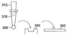
피에조 방식의 분주장치는, 도 17에 나타나 있는 바와 같이, 선단에 토출부를 가지는 피에조 칩(302)을 구비하고 있다. 피에조 칩(302)은 토출부에 연결되는 액체 저장소를, 피에조 소자를 구비한 구동부에 의해 가압함으로써 토출부에서 액체방울(306)을 토출 한다. 구동부를 제어해서 일정한 크기의 액체방울을 토출하기 위해서, 피에조 분주제어부(304)가 설치되어 있고, 피에조 분주제어부(304)에서 설정된 피에조 소자 구동의 파라미터에 따라서 피에조 칩(302)로부터 액체방울(306)을 토출한다.The piezoelectric dispensing apparatus is provided with the
실린지 방식의 분주장치는, 도 18에 나타나 있는 바와 같이, 실린지 펌프 (310)에 연결되는 프로브(312)로부터의 액체방울(6)의 토출을, 실린지 펌프(310)를 작동시키는 모터(314)를 구동함으로써 행한다. 프로브(312)의 선단에는 디스포저블(1회용) 칩(316)이 설치되는 일도 있다. 칩(316)은 샘플 또는 시약마다 부착된다. 실린지 펌프(310)의 동작 파라미터가 설정된 것으로 되도록, 실린지 분주제어부(318)에 의해 모터(314)의 구동을 제어함으로써, 소정의 크기의 액체방울(306)이 토출된다.As shown in FIG. 18, the syringe type dispensing apparatus is configured to operate the
토출하고자 하는 샘플이나 시약의 점성 등의 액성에 의해 토출조건을 설정하고 있지만, 온도 등 환경조건의 변화에 의해 토출되는 액체방울의 크기는 변화한다. 또한, 액체방울이 미량이 될수록 정량성에 걸쳐 간다.Although the discharge conditions are set by the liquidity such as the viscosity of the sample or reagent to be discharged, the size of the discharged droplets is changed by the change of environmental conditions such as temperature. In addition, the smaller the droplet, the more quantitative.
본 발명은, 분주해야 할 위치에 정확하게 분주할 수 있게 하는 것을 목적으로 하는 것이다.An object of the present invention is to enable dispensing accurately at a position to be dispensed.
(발명의 개시)(Initiation of invention)
본 발명의 제 1 국면은, 분주해야 할 위치를 지정 할 수 있고, 지정한 위치에 자동적으로 분주할 수 있도록 하는 분주장치에 의해 상기 목적을 달성하는 것이다.A first aspect of the present invention is to achieve the above object by means of a dispensing apparatus which can designate a position to be dispensed and automatically dispenses to a designated position.
이 제 1 국면의 분주장치는, 샘플 또는 시약을 적하하는 분주소자를 구비한 분주기구와, 아래쪽의 화상을 판독하는 화상판독장치와, 샘플 또는 시약이 분주되는 대상물을 상면에 지지하고, 수평면 내에서 이동해서 상기 대상물을 적어도 상기분주소자의 아래쪽의 분주위치 및 상기 화상판독장치의 아래쪽의 화상판독 위치에 위치결정하는 가동 테이블과, 상기 화상판독장치가 판독한 화상을 표시하는 모니터부와, 상기 모니터부에 표시된 상기 대상물의 화상에 기초하여 대상물 위의 분주위치를 지정하는 분주위치 지정부와, 상기 분주위치 지정부가 지정한 대상물 위의 분주위치가 상기 분주기구의 분주소자의 아래쪽으로 오도록 상기 대상물과 분주소자의 상대적 위치결정을 행하고 상기 분주기구에 의한 분주동작을 제어하는 분주제어부를 구비하고 있다.The dispensing apparatus of the first aspect includes a dispensing mechanism including a dispensing device for dropping a sample or reagent, an image reading apparatus for reading a lower image, and an object to which the sample or reagent is dispensed on the upper surface, and in a horizontal plane. A movable table for moving the to and positioning the object at least at a dispensing position below the distributor and at an image reading position below the image reading apparatus, a monitor unit displaying an image read by the image reading apparatus, and A dispensing position designating unit for designating a dispensing position on the object based on the image of the object displayed on the monitor unit; and the dispensing position on the object designated by the dispensing position designating unit so that the dispensing position is below the dispenser of the dispensing mechanism. A dispensing control unit which performs relative positioning of the dispensing address and controls dispensing operation by the dispensing mechanism is provided. There.
제 1 국면의 분주장치에 따르면, 화상판독장치가 판독한 화상을 모니터부에 표시하고, 그 모니터부에 표시된 대상물의 화상에 기초하여 대상물 위의 분주위치를 지정함으로써, 분주제어부가 대상물과 분주소자의 상대적 위치결정을 행하는 분주기구에 의한 분주동작을 제어하도록 하였기 때문에, 모니터부에 표시된 화상 위에서 분주위치를 지정함으로써, 그 지정된 위치에 시약이나 샘플이 자동적으로 분주된다.According to the dispensing apparatus of the first aspect, an image reading apparatus displays an image read on a monitor portion, and the dispensing control unit assigns a dispensing position on the object based on the image of the object displayed on the monitor portion, thereby dispensing the object and the dispense address. Since the dispensing operation by the dispensing mechanism that performs relative positioning of the child is controlled, the dispensing position is automatically dispensed at the designated position by specifying the dispensing position on the image displayed on the monitor unit.
분주기구는 분주소자를 복수개 구비하고, 공통의 분주위치 또한 다른 분주위치에 복수 종류의 시약이나 샘플을 주입할 수 있도록 하여도 된다.The dispensing mechanism may be provided with a plurality of dispensing addresses, and may be capable of injecting a plurality of types of reagents or samples into a common dispensing position and another dispensing position.
분주위치정보 작성부를 더 구비하고, 분주위치 지정부가 지정하여 분주동작이 행해진 대상물 위의 분주위치에 관한 분주위치 정보를 작성하도록 하여도 된다. 이에 따라, 대상물의 어느 위치에 분주가 행해졌는지를 정보로서 남길 수 있다.A dispensing position information creating unit may be further provided, and the dispensing position designating unit may designate dispensing position information on the dispensing position on the object on which the dispensing operation is performed. In this way, it is possible to leave as information the position at which the object is divided.
또한, 분주위치정보 작성부는 작성된 분주위치 정보를 외부로 출력할 수 있는 것으로 하여도 된다. 시약이나 샘플이 분주된 대상물은, 질량분석장치 등의 분석 장치로 이송되거나, 필요에 따라서 전처리장치에 이송된다. 그때, 이송처의 분석 장치나 전처리장치에서는, 분주위치정보 작성부가 작성해 출력한 분주위치 정보를 받아 들이고, 그 대상물의 분주된 위치를 파악함으로써 분주위치의 분석을 행하거나, 분주위치에 전처리를 실시하는 작업을 용이하게 행할 수 있게 된다.Further, the dispensing position information creating unit may output the generated dispensing position information to the outside. The object to which the reagent or sample is dispensed is transferred to an analytical device such as a mass spectrometer or a pretreatment device as necessary. At this time, the analysis device and the preprocessing device of the transfer destination accept the dispensing position information created and output by the dispensing position information creating unit and analyze the dispensing position by grasping the dispensing position of the object, or preprocess the dispensing position. It is possible to easily perform the work.
분주위치 지정부는 모니터부에 표시된 대상물의 화상 위에서, 예를 들면, 커서에 의해 분주위치를 지정하도록 할 수 있다.The dispensing position designation unit can cause the dispensing position to be designated by, for example, a cursor on the image of the object displayed on the monitor unit.
분주동작을 모니터해서 분주소자로부터의 토출량을 조정하기 위해서, 분주소자의 선단부를 촬상하는 촬상장치를 더 구비할 수 있다. 그 경우, 분주기구가 복수의 분주소자를 구비하고 있는 경우에는, 촬상장치는 분주소자 중에서 분주동작을 행하는 분주소자의 선단부를 촬상하도록, 분주동작을 행하는 분주소자의 변경에 따라 이동할 수 있도록 이동기구에 지지되어 있다.In order to monitor the dispensing operation and to adjust the discharge amount from the dispenser, an image pickup device for imaging the distal end of the dispenser may be further provided. In this case, when the dispensing mechanism is provided with a plurality of divider addresses, the imaging device moves so as to move in accordance with the change of the divider address performing the dispensing operation so as to image the distal end portion of the divider performing dispensing operation among the divider addresses. Is supported.
본 발명의 제 2 국면은, 분주소자를 새롭게 장착하거나, 교환했을 때에도 정확한 분주동작을 행하는 것이 가능하도록 하는 것에 의해 상기 목적을 달성하는 것이다.The second aspect of the present invention achieves the above object by enabling accurate dispensing operation even when a dispenser is newly mounted or replaced.
그 제 2 국면의 분주장치는, 샘플 또는 시약을 적하하는 분주소자가 착탈 가능하게 되어 있는 분주기구와, 아래쪽의 화상을 판독하는 화상판독장치와, 샘플 또는 시약이 분주되는 대상물을 상면에 지지하고, 수평면 내에서 이동해서 상기 대상물을 적어도 상기 분주소자의 아래쪽의 분주위치 및 상기 화상판독장치의 아래쪽의 화상판독 위치에 위치결정하는 가동 테이블과, 상기 분주기구에 의해 상기 가동 테이블 상의 소정의 위치에 분주를 행했을 때의 상기 화상판독장치에 의한 판독 화상 에 기초하여 분주위치를 검출하고, 동시에 판독한 상기 가동 테이블 상의 기준이 되는 베이스 포인트를 기초로 해서 분주위치의 교정을 행하는 교정부를 구비하고 있다.The dispensing apparatus of the second aspect supports a dispensing mechanism in which a dispensing device for dropping a sample or a reagent is detachable, an image reading apparatus for reading a lower image, and an object to which the sample or reagent is dispensed on the upper surface. And a movable table for moving the object within a horizontal plane and positioning the object at least at a dispensing position below the dispenser and an image reading position below the image reading apparatus, and at a predetermined position on the movable table by the dispensing mechanism. A calibration unit is provided for detecting a dispensing position on the basis of a read image by the image reading device when dispensing, and for correcting the dispensing position based on a base point serving as a reference on the movable table read at the same time. .
분주기구의 분주소자는 소정의 위치에 장착되도록 되어 있지만, 장착된 분주소자의 분주위치가 항상 같은 위치가 되도록 하기 위해서는, 분주소자 장착 부분에 고도의 기계가공 정밀도가 요구된다. 또한, 개개의 분주소자에는 기기차가 있다. 그 때문에, 분주위치가 소정의 위치가 되도록 분주소자의 장착을 조정하려고 하면 고도의 기계가공 정밀도와 숙련한 조정능력이 요구된다.The dispensing device of the dispensing mechanism is designed to be mounted at a predetermined position. However, in order to ensure that the dispensing position of the dispensing device is always at the same position, a high degree of machining precision is required in the dispensing device mounting portion. In addition, there is a vehicle for each addressee. For this reason, when attempting to adjust the dispensing of the dispenser so that the dispensing position is a predetermined position, high machining precision and skilled adjusting ability are required.
그러나, 제 2 국면의 액체 분주장치에서는, 분주기구의 분주소자가 착탈 가능하게 되고 있고, 분주소자에 의해 가동 테이블 상의 소정의 위치에 분주를 행했을 때의 화상판독장치에 의한 판독 화상에 기초하여 분주위치를 검출하고, 동시에 판독된 가동 테이블 상의 기준이 되는 베이스 포인트를 기초로 해서 분주위치의 교정을 행하도록 했으므로, 분주소자의 장착이나 교환에 따른 조정작업이 간단한 것으로 된다.However, in the liquid dispensing apparatus of the second aspect, the dispensing device of the dispensing mechanism is detachable, and based on the read image by the image reading apparatus when dispensing is performed at a predetermined position on the movable table by the dispensing device. Since the dispensing position is detected and the dispensing position is corrected on the basis of the base point serving as a reference on the movable table read at the same time, the adjustment work according to the mounting or replacement of the dispensing address becomes simple.
제 2 국면은 분주소자를 복수개 구비한 것도 포함하고 있다. 그 경우, 교정부는 각 분주소자에 대해서 교정을 행한다.The second aspect also includes a plurality of branch addresses. In that case, the calibrating unit calibrates each minute addresser.
본 발명의 제 3 국면은, 액체 분주 기타의 처리를 실시한 위치에 관한 정확한 정보를 작성할 수 있게 하는 위치정보 판독장치에 의해 상기 목적을 달성하는 것이다.A third aspect of the present invention achieves the above object by a positional information reading apparatus which makes it possible to produce accurate information about a position where liquid dispensing or the like has been processed.
그 제 3 국면의 위치정보 판독장치는, 테이블 상의 대상물의 화상을 판독하는 화상판독장치와, 상기 화상판독장치가 판독한 화상을 기초로 하고, 그 화상 중 에서 지정된 위치의 정보 또는 검출된 위치의 정보를 그 대상물 위의 기준이 되는 복수의 레퍼런스 포인트를 기초로 해서 작성하는 위치정보 작성부를 구비하고 있다.The position information reading apparatus of the third aspect is based on an image reading apparatus for reading an image of an object on a table, and an image read by the image reading apparatus, and the information of the specified position or the detected position among the images. And a positional information creating unit for creating information based on a plurality of reference points serving as a reference on the object.
대상물 위의 지정 위치의 정보를 얻는 경우에는, 화상판독장치가 판독한 화상을 표시하는 모니터부와, 상기 모니터부에 표시된 상기 대상물의 화상에 기초하여 대상물 위의 위치를 지정하는 위치지정부를 더 구비하고, 상기 위치정보 작성부는 상기 위치지정부가 지정한 대상물 위의 위치의 정보를 작성하는 것으로 한다.In the case of obtaining the information of the designated position on the object, the apparatus further includes a monitor unit for displaying the image read by the image reading apparatus, and a positioning unit for designating the position on the object based on the image of the object displayed on the monitor unit. The location information creating unit is to create the information on the location on the object designated by the location designating unit.
위치정보 판독장치는, 화상판독장치가 판독한 화상을 기초로 하여, 그 화상 중에서 지정된 위치의 정보 또는 검출된 위치의 정보를 그것의 대상물 상의 기준이 되는 복수의 레퍼런스 포인트를 기초로 해서 작성하도록 하였으므로, 레퍼런스 포인트를 기초로 해서 대상물 내에서의 위치 정보를 정확하게 정할 수 있다.The position information reading apparatus is configured to create the information of the designated position or the detected position information in the image based on the plurality of reference points as a reference on the object based on the image read by the image reading apparatus. Based on the reference point, the position information within the object can be accurately determined.
그리고, 대상물을 분석 장치 등에 이동시킨 경우에도, 그 레퍼런스 포인트를 기초로 해서 그 위치 정보로부터 대상물 내에서의 목적으로 하는 위치에 정확하게 위치결정할 수 있게 된다.And even when the object is moved to an analysis apparatus or the like, it is possible to accurately position the target position in the object from the positional information based on the reference point.
상기 화상판독장치는 대상물의 화상과 함께 상기 테이블의 화상도 판독하는 것으로 하고, 상기 위치정보 작성부는 상기 대상물 위의 위치를 테이블 상의 기준이 되는 복수의 베이스 포인트를 기초로 해서 작성하는 것으로 할 수 있다. 이에 따라, 대상물 내에서의 목적으로 하는 위치의 정보를 베이스 포인트를 기초로 해서 정확하게 정할 수 있다. 그리고, 대상물을 일단 테이블로부터 제거하고, 다시 테이블에 부착한 경우에도, 그 베이스 포인트를 기초로 해서 그 위치 정보로부터 대상 물 내에서의 원하는 위치에 정확하게 위치결정할 수 있게 된다.The image reading apparatus may read an image of the table together with an image of an object, and the position information creating unit may create a position on the object based on a plurality of base points serving as a reference on the table. . Thereby, the information of the target position in an object can be correctly determined based on a base point. And even when the object is once removed from the table and attached to the table again, it is possible to accurately position the desired position in the object from the positional information based on the base point.
위치정보 작성부는 작성한 위치 정보를 외부로 출력할 수 있는 것으로 하면, 그 대상물을 분석 장치 등 다른 장치에 이송한 경우에도, 그 위치 정보를 이용해서 목적으로 하는 위치에 정확하게 위치결정할 수 있다.Assuming that the position information creating unit can output the created position information to the outside, even when the object is transferred to another apparatus such as an analysis apparatus, the position information creation unit can accurately position the target position using the position information.
본 발명의 제 4 국면은, 액체 분주 기타의 처리를 실시한 위치에 관한 정확한 정보를 작성할 수 있도록 하는 샘플 플레이트에 의해 상기 목적을 달성하는 것이다.A fourth aspect of the present invention is to achieve the above object by a sample plate that allows accurate information on the position where liquid dispensing or the like has been processed.
그 제 4 국면의 샘플 플레이트는, 위치 정보를 정확하게 얻는데에 적합한 것으로서, 샘플 또는 시약이 분주되는 표면을 가지는 판상체이며, 그 표면 내에 위치의 기준이 되는 복수의 마크를 구비하고 있다.The sample plate of the fourth aspect is a plate-like body having a surface on which a sample or a reagent is dispensed, which is suitable for accurately obtaining positional information, and has a plurality of marks serving as a reference for position in the surface.
그 샘플 플레이트는 샘플 또는 시약이 분부되는 표면 내에 위치의 기준이 되는 복수의 마크를 구비하고 있으므로, 샘플 플레이트 내의 분주위치의 정확한 위치 정보를 작성하는데에 바람직하다.Since the sample plate has a plurality of marks serving as a reference of the position in the surface on which the sample or reagent is to be dispensed, it is preferable to prepare accurate position information of the dispensing position in the sample plate.
본 발명의 제 5 국면은, 분주장치를 소형화하는 동시에, 분주상태를 모니터할 수 있는 기구를 구비함으로써 상기 목적을 달성하는 것이다.A fifth aspect of the present invention achieves the above object by providing a mechanism capable of downsizing the dispensing device and monitoring the dispensing state.
그 제 5 국면의 분주장치는, 샘플 또는 시약을 적하하는 노즐을 구비한 분주기구와, 샘플 또는 시약이 분주되는 대상물을 상면에 지지하고, 수평면 내에서 이동해서 상기 대상물을 상기 노즐의 아래쪽으로 위치결정하는 가동 테이블과, 평면 상은 상기 가동 테이블의 이동 범위 내에 있어서, 상기 가동 테이블과 접촉하지 않는 위쪽의 위치에 부착되고, 상기 노즐의 선단부를 비스듬하게 위쪽에서 촬상하는 촬상장치를 구비하고 있다.The dispensing apparatus of the fifth aspect includes a dispensing mechanism including a nozzle for dropping a sample or reagent, and an object to which the sample or reagent is dispensed on the upper surface, and moves in a horizontal plane to position the object below the nozzle. The movable table to be determined and the planar image are attached to the upper position which is not in contact with the movable table within the moving range of the movable table, and are provided with an imaging device which picks up the tip of the nozzle at an obliquely upward position.
분주상태를 모니터하기 위한 촬상장치를, 수평방향에서 각도를 가지게 해서 비스듬하게 위쪽에 배치하도록 한 것에 의해, 가동 테이블과 간섭하지 않고 가동 테이블의 이동 범위 내에 설치 할 수 있어, 분주장치가 소형이 된다.By arranging the image pickup device for monitoring the dispense state at an angle in the horizontal direction and obliquely upwards, the image pickup device can be installed within the moving range of the movable table without interfering with the movable table, thereby making the dispensing device compact. .
노즐의 선단부를 사이에 끼워 촬상장치와는 반대측의 위치에 광원을 배치해도 되며, 그 경우, 그 광원은 그것이 발생하는 빛이 대상물의 표면에서 반사해 노즐의 선단부를 경유해서 촬상장치에 입사하는 방향을 향하게 된다. 이와 같은 광원을 설치함으로써, 노즐 선단부에 형성되는 샘플 또는 시약의 방울을 모니터할 경우에는, 그 방울의 화상을 투과강으로 촬영 할 수 있게 되어, 보다 선명한 화상을 얻어 정확한 모니터를 행하는 것이 가능하게 된다.The light source may be disposed at a position opposite to the image pickup device with the tip portion of the nozzle interposed therebetween, in which case the light source reflects light from the surface of the object and enters the image pickup device via the tip of the nozzle. Will face. By providing such a light source, when monitoring the droplet of the sample or reagent formed in the tip of the nozzle, the image of the droplet can be photographed by the transmission steel, so that a clearer image can be obtained and accurate monitoring can be performed. .
촬상장치는 노즐의 선단부의 화상과 함께 노즐의 하부에 있는 대상물 표면의 화상도 촬상하도록 설정해 둘 수도 있다. 그 경우에는, 노즐 선단부의 모니터와 함께, 대상물 표면의 상태도 모니터할 수 있게 되어, 보다 많은 정보를 얻을 수 있다. 예를 들면, 목적으로 하는 포지션에 적확하게 샘플이나 시약이 분주되고 있는지 아닌지를 확인할 수 있게 되거나, 또한 예를 들면, 샘플이나 시약이 분주되는 대상물이 막인 경우, 분주 전후의 막의 상태를 관찰하거나, 반응중의 막 상태의 시간에 따른 변화의 관찰을 하는 것도 가능하게 된다.The imaging device may be set to capture an image of the surface of the object under the nozzle together with the image of the tip of the nozzle. In that case, the state of the surface of the object can be monitored together with the monitor of the tip of the nozzle, so that more information can be obtained. For example, it is possible to confirm whether or not a sample or reagent is properly dispensed at a desired position, or, for example, when the object to which the sample or reagent is dispensed is a membrane, observe the state of the membrane before and after dispensing, It is also possible to observe changes over time of the film state during the reaction.
본 발명의 제 6 국면은, 피에조 칩에 의한 분주방법과 분주장치에 있어서, 분주 시작전에 피에조 칩 선단의 액량 조정을 쉽게 하는 것에 의해 상기 목적을 달성하고자 하는 것이다.A sixth aspect of the present invention is to achieve the above object by easily adjusting the amount of liquid in the tip of the piezo chip before dispensing, in the dispensing method and dispensing apparatus using a piezo chip.
제 6 국면의 분주방법은, 토출부가 아래쪽을 향하는 개구를 가지고, 그 토출부에 연결되는 공간에 충전된 액을, 피에조 소자를 구비한 구동부에 의해 가압함으로써 그 토출부에서 액체방울을 토출하는 피에조 칩와, 상기 공간에 충전된 액의 압력상태를 조정할 수 있는 압력제어기구와, 토출부의 화상을 촬상하는 촬상장치를 구비한 분주 유닛에 있어서의 분주방법에 있어서, 상기 공간에 액을 충전하기 전의 토출부의 화상을 촬상장치에 의해 취득하여 기억시켜 두고, 피에조 칩으로부터의 분주동건을 시작하기 전의 준비 단계로서, 상기 공간에 액을 충전한 후, 촬상장치에 의해 토출부의 화상을 받아들여 액 충전 전의 화상과의 차이를 구하면서 압력제어기구를 제어하여, 액이 토출부에서 나타난 후, 액 충전 전의 화상과의 차이가 없어어질 때까지 액을 후퇴시키는 공정을 설치한다.In the sixth aspect, the dispensing method includes a piezoelectric discharger having an opening in which the discharge portion faces downward, and discharging droplets from the discharge portion by pressurizing a liquid filled in a space connected to the discharge portion by a driving portion having a piezo element. A dispensing method in a dispensing unit having a chip, a pressure control mechanism capable of adjusting a pressure state of a liquid filled in the space, and an image pickup device for imaging an image of the discharging portion, wherein the discharging before filling the liquid into the space is performed. A negative image is acquired by the imaging device and stored therein, and as a preparation step before starting the dispensing condition from the piezo chip, the liquid is filled in the space, and the image before the liquid filling is received by the imaging device. The pressure control mechanism is controlled while finding the difference between the liquid and the liquid until the liquid disappears from the image before the liquid fills up. Install a process to retract
액을 피에조 칩에 충전하기 전의 피에조 칩 선단의 화상은 액이 토출부에서 나타나고 있지 않은 상태를 나타내고 있으며, 액을 피에조 칩에 충전할 때의 기준이 되는 상태이다. 그후에 피에조 칩에 액을 넣고, 압력제어기구에 의해 압력을 가해서 피에조 칩의 토출부까지 액을 공급한다. 이 상태가 액을 충전한 상태가 된다. 액의 충전 시작으로부터 피에조 칩의 토출부의 화상을 취득하고, -충전전의 화상과의 차이를 취해 간다. 압력제어기구에 의해 가압해가, 그 화상의 차이로서 토출부에서 여분 액량이 표시되는 것을 확인할 수 있으면, 거기에서 압력제어기구를 음압으로 되도록 압력제어에 피드백을 걸고, 여분 액량이 보이지 않는 위치에서 압력제어를 고정한다. 이것으로 분주동작전의 준비가 완성되고, 그 상태로부터 토출에 의해 분주를 시작한다.The image of the tip of the piezo chip before the liquid is filled into the piezo chip shows a state in which the liquid is not present in the discharge portion, and is a state used as a reference when the liquid is filled into the piezo chip. Thereafter, the liquid is poured into the piezo chip, and pressure is applied by the pressure control mechanism to supply the liquid to the discharge portion of the piezo chip. This state becomes the state which filled the liquid. An image of the discharge portion of the piezo chip is acquired from the start of the filling of the liquid, and the difference from the image of the charging is taken. If pressurization by the pressure control mechanism confirms that the excess liquid amount is displayed at the discharge part as a difference in the image, feedback is given to the pressure control so that the pressure control mechanism becomes negative pressure there. Fix pressure control. This completes preparation before the dispensing operation, and dispensing is started by discharging from that state.
이 준비 단계의 공정을 제어장치에 의해 자동화하면, 피에조 칩에의 액의 충전을 시작하는 것 만으로, 피에조 칩에 의한 분주를 할 수 있게 될 때까지 자동적으로 압력조정이 실행된다.When the process of this preparation step is automated by a control apparatus, pressure adjustment is automatically performed until it becomes possible to dispense with a piezo chip only by starting the filling of a liquid to a piezo chip.
이 제 6 국면의 분주방법이 실행되는 본 발명의 분주장치는, 토출부가 아래쪽을 향하는 개구를 가지고, 그 토출부에 연결되는 공간에 충전된 액을, 피에조 소자를 구비한 구동부에 의해 가압함으로써 그 토출부에서 액체방울을 토출하는 피에조 칩을 구비한 분주 유닛과, 상기 공간에 충전된 액의 압력상태를 조정할 수 있는 압력제어기구와, 토출부의 화상을 촬상하는 촬상장치와, 촬상장치가 촬상한 화상을 기억하는 기억장치와, 상기 공간에 액을 충전하기 전의 토출부의 화상으로 기억장치에 기억된 화상과 상기 공간에 액을 충전한 후의 화상을 비교하여, 액이 토출부에서 나타난 후, 액 충전전의 화상과의 차이가 없어질 때까지 후퇴하도록 압력제어기구를 제어하는 제어장치를 구비하고 있다.The dispensing apparatus of the present invention, in which the dispensing method of the sixth aspect is executed, has a discharge portion having an opening facing downward, and pressurizes a liquid filled in a space connected to the discharge portion by a driving portion provided with a piezo element. A dispensing unit having a piezo chip for discharging droplets from the discharge portion, a pressure control mechanism capable of adjusting the pressure state of the liquid filled in the space, an image pickup apparatus for picking up the image of the discharge portion, The liquid storage device stores the image, and the image stored in the storage device as the image of the discharge unit before the liquid is filled in the space, and the image after the liquid is filled in the space. A control device for controlling the pressure control mechanism so as to retreat until the difference with the previous image disappears.
촬상장치는 토출부의 화상을 수평방향으로부터 촬상하도록 설치되어 있으면, 피에조 칩에의 액의 충전을 더 정확하게 행할 수 있다.If the imaging device is provided so as to image the discharge part from the horizontal direction, it is possible to more accurately fill the piezo chip with the liquid.
종래 매뉴얼로 피에조 칩 선단의 화상을 보면서 미묘한 압력제어를 하지 않으면 안되었지만, 본 발명에서는, 피에조 칩에 액을 충전하기 전의 토출부의 화상을 촬상장치에 의해 받아들여서 기억시켜 두고, 액의 충전 시작후, 촬상장치에 의해 토출부의 화상을 받아들여서 액 충전전의 화상과의 차이를 구하면서 압력제어기구를 제어하고, 액이 토출부에서 나타난 후, 액 충전전의 화상과의 차이가 없어질때까지 액을 후퇴시키도록 했으므로, 피에조 칩 선단의 액량 조정을 용이하게 행할 수 있게 된다.Although subtle pressure control has to be performed while conventionally viewing the image of the tip of the piezo chip, in the present invention, the image of the discharge portion before the liquid is filled in the piezo chip is received and stored by the imaging device, and after the liquid starts to be filled. The pressure control mechanism is controlled by taking an image of the discharge portion by the image pickup device to obtain a difference from the image before the liquid filling, and after the liquid appears at the discharge portion, the liquid is retracted until the difference with the image before the liquid filling disappears. Since it is made to make it, the amount of liquid of a tip of a piezo chip can be adjusted easily.
또한, 이 공정을 자동화하면, 피에조 칩에의 액의 충전을 시작하는 것만으로, 피에조 칩에 의한 분주를 할 수 있게 될 때까지 자동적으로 압력조정이 실행된다. 또한, 대기중에도 모니터를 속행하도록 하면, 항상 피에조 칩 선단의 상태를 일정하게 유지하는 것이 가능하게 된다.In addition, when this process is automated, pressure adjustment is automatically performed until the piezo chip can be dispensed by simply filling the piezo chip with liquid. In addition, if the monitor is continued even in the air, the state of the tip of the piezo chip can be kept constant.
본 발명의 제 7 국면은, 미량의 샘플 액이나 시약 액의 분주의 정량성을 높임으로써 상기 목적을 달성하고자 하는 것이다.A seventh aspect of the present invention is to achieve the above object by enhancing the quantitative dispensing of trace amounts of sample liquid or reagent liquid.
그 제 7 국면의 정량분주방법은, 분주 유닛의 토출부에서 나오는 액체방울의 화상을 취득하고, 그 화상으로부터 액체방울의 크기를 구해서 액체 방울의 분주량을 제어한다.According to the quantitative dispensing method of the seventh aspect, an image of a liquid droplet coming out of the discharging unit of the dispensing unit is acquired, the size of the liquid droplet is obtained from the image, and the dispensing amount of the liquid droplet is controlled.
즉, 그 정량분주방법은, 다음 스텝 (A)에서 (C)를 구비하고 있다.That is, the quantitative dispensing method is equipped with (C) in the next step (A).
(A) 상기 토출부에서 토출된 액체방울의 화상을 취득하는 스텝.(A) acquiring the image of the droplet discharged from the discharge unit.
(B) 그 받아들여진 화상에 기초하여 액체방울의 크기를 구하는 스텝.(B) calculating the size of the droplet based on the received image.
(C) 그 구한 액체방울의 크기에 기초하여 액체방울의 분주량이 소정값이 되도록 분주 유닛의 토출구동부에의 제어신호의 파라미터를 조절하는 스텝.(C) adjusting the parameter of the control signal to the discharge drive section of the dispensing unit so that the dispensing amount of the droplet is a predetermined value based on the size of the liquid droplet obtained.
이에 따라, 샘플 액이나 시약 액 등의 pL∼μL의 미량분주에 있어서 정량성이 향상한다.Thereby, the quantitative property improves in the microdispensing of pL-microliters, such as a sample liquid and a reagent liquid.
스텝 (B)에서 구하는 액체방울의 크기는, 예를 들면 액체방울의 직경이나 반경이다.The size of the droplet obtained in step (B) is, for example, the diameter or radius of the droplet.
그 액체방울의 크기를 구하는 스텝은 화상처리를 사용한 자동계산에 의해 행 할 수 있다. 그러한 화상처리 프로그램은 용이하게 입수할 수 있다. 화상처리를 사용한 자동계산을 이용하면, 빠르고 정확하게 액체방울의 크기를 구할 수 있다.The step of calculating the size of the droplet can be performed by automatic calculation using image processing. Such image processing programs can be easily obtained. Using automatic calculation using image processing, it is possible to quickly and accurately determine the size of a droplet.
또한, 액체방울의 크기를 구하는 스텝은 화상 상에서 수동계산에 의해 행할 수도 있다. 수동계산에 의하면, 화상처리 프로그램에 필요한 비용을 삭감할 수 있다.In addition, the step of calculating the size of the droplet may be performed by manual calculation on the image. According to the manual calculation, the cost required for the image processing program can be reduced.
분주 유닛은, 선단의 토출부에 연결되는 공간에 충전된 액을, 피에조 소자를 구비한 구동부에 의해 가압함으로써 그 토출부에서 액체방울을 토출하는 피에조 헤드를 구비한 피에조 분주방식의 것으로 할 수 있다. 그 경우, 제어신호의 파라미터는, 피에조 소자에의 인가 전압의 크기, 인가 전압의 상승 시간, 인가 시간, 인가 전압의 하강 시간 중에서 적어도 1개를 포함하는 것으로 할 수 있다.The dispensing unit may be of the piezo dispensing method having a piezo head for discharging droplets from the discharging portion by pressurizing the liquid filled in the space connected to the discharging portion at the distal end by the driving portion having the piezo element. . In that case, the parameter of the control signal may include at least one of the magnitude of the voltage applied to the piezoelectric element, the rise time of the applied voltage, the application time, and the fall time of the applied voltage.
또한, 분주 유닛은, 실린지 펌프에 의한 분주방식의 것으로 할 수도 있다. 그 경우, 제어신호의 파라미터는, 실린지 펌프의 플런저의 스트로크, 속도, 가속 중에서 적어도 1개를 포함하는 것으로 할 수 있다.In addition, the dispensing unit may be a dispensing system using a syringe pump. In that case, the control signal parameter may include at least one of the stroke, speed, and acceleration of the plunger of the syringe pump.
실린지 펌프에 의한 분주방식에서는, 액체방울의 크기를 구하는 화상은, 토출부의 선단에 구슬 형태로 매달린 상태의 액체방울의 화상으로 할 수 있다.In the dispensing method using a syringe pump, the image for obtaining the size of the droplet can be an image of the droplet in a state of being suspended in a bead form at the tip of the discharge portion.
제어신호의 파라미터를 조절하는 스텝은, 토출구동부를 제어하는 제어부에 의한 자동제어에 의해 행할 수 있다. 그 경우에는 작업자의 공정수가 적어진다.The step of adjusting a parameter of a control signal can be performed by automatic control by the control part which controls a discharge drive part. In that case, the number of processes for the worker is small.
또한, 제어신호의 파라미터를 조절하는 스텝은, 토출구동부를 제어하는 제어부에 입력함으로써 행할 수도 있다. 그 경우에는 시스템이 간단해진다.In addition, the step of adjusting a parameter of a control signal can also be performed by inputting into the control part which controls a discharge drive part. In that case, the system is simplified.
도 1은 분주장치의 일 실시예를 개략적으로 나타낸 사시도이다.1 is a perspective view schematically showing an embodiment of a dispensing apparatus.
도 2는 동 실시예에 있어서 샘플 플레이트 등이 배치된 테이블의 상면을 나타낸 평면도이다.2 is a plan view showing an upper surface of a table on which a sample plate or the like is disposed in the embodiment.
도 3은 동 실시예에 있어서의 분주기구를 나타낸 단면도이다.3 is a sectional view showing a dispensing mechanism in the embodiment.
도 4는 동 실시예를 기능으로서 나타낸 블록도이다.4 is a block diagram showing the embodiment as a function.
도 5는 제 5 국면의 분주장치의 일 실시예를 나타낸 정면도이다.5 is a front view showing an embodiment of a dispensing device of a fifth aspect.
도 6은 동 실시예에 있어서의 노즐 선단부 부근을 나타낸 개략정면도이다.Fig. 6 is a schematic front view showing the vicinity of the tip of the nozzle in the embodiment.
도 7은 제 6 국면의 일 실시예를 개략적으로 나타낸 블록도이다.7 is a block diagram schematically illustrating an embodiment of a sixth aspect.
도 8은 동 장치에 있어서의 피에조 칩의 일례를 개략적으로 나타낸 단면도이다.8 is a cross-sectional view schematically showing an example of a piezo chip in the apparatus.
도 9는 동 실시예의 동작을 나타낸 흐름도이다.9 is a flowchart showing the operation of the embodiment.
도 10은 제 7 국면의 일 실시예의 방법이 적용되는 장치를 개략적으로 나타낸 블록도이다.10 is a schematic block diagram of an apparatus to which the method of the embodiment of the seventh aspect is applied.
도 11은 동 장치에 있어서의 피에조 칩의 일례를 개략적으로 나타낸 단면도이다.11 is a cross-sectional view schematically showing an example of a piezo chip in the apparatus.
도 12는 동 실시예에 있어서의 제어 파라미터를 나타낸 파형도이다.12 is a waveform diagram showing control parameters in the embodiment.
도 13은 동 실시예의 동작을 나타낸 흐름도이다.13 is a flowchart showing the operation of the embodiment.
도 14는 동 국면의 다른 실시예의 방법이 적용되는 장치를 개략적으로 나타낸 블록도이다.14 is a block diagram schematically illustrating an apparatus to which the method of another embodiment of the present invention is applied.
도 15는 동 실시예에 있어서의 분주양식을 나타낸 프로브 선단부의 정면도이다.Fig. 15 is a front view of the probe tip portion showing the dispensing style in the same embodiment.
도 16은 제 5 국면의 분주장치에 대응한 종래의 분주장치를 나타낸 정면도이다.Fig. 16 is a front view showing a conventional dispensing apparatus corresponding to the dispensing apparatus of the fifth aspect.
도 17은 종래의 피에조 방식의 분주장치를 개략적으로 나타낸 블록도이다.17 is a block diagram schematically showing a conventional piezo system dispensing apparatus.
도 18은 종래의 실린지 방식의 분주장치를 개략적으로 나타낸 블록도이다.18 is a block diagram schematically showing a conventional syringe dispenser.
도 1은 본 발명의 액체 분주장치의 일 실시예를 개략적으로 나타낸 것이다.Figure 1 schematically shows an embodiment of the liquid dispensing apparatus of the present invention.
4는 분주기구인 프린트 헤드이며, 시약 등을 분주하는 피에조 소자를 구비한 4개의 분주소자(10-1∼10-4)이 일렬로 나란하게 장착되어 있다. 분주소자(10-1∼10-4)의 위치는 고정되어 있다. 분주소자(10-1∼10-4)로부터의 분주량을 제어하기 위해서, 분주소자(10-1∼10-4)에 걸리는 압력을 조정하기 위한 압력제어부(7)가 장치 본체의 전방면에 부착되어 있으며, 분주소자(10-1∼10-4) 내의 압력을 조정하는 손잡이(8)가 각 분주소자(10-1∼10-4)에 대응해서 4개 배열되어 있다.4 is a print head which is a dispensing mechanism, and four dispensing devices 10-1 to 10-4 having piezo elements for dispensing reagents and the like are mounted side by side. The position of the addressers 10-1 to 10-4 is fixed. In order to control the amount of dispensing from the dispenser 10-1 to 10-4, a
분주하고자 하는 샘플 플레이트를 테이블과 함께 화상으로서 받아들이기 위해서 화상판독장치로서 스캐너(6)가 배치되어 있다. 스캐너(6)의 위치도 고정되어 있다.In order to receive the sample plate to be dispensed together with the table as an image, the
테이블(2)은 수평면 내에서 이동할 수 있는 가동 테이블이며, 그 테이블(2) 위에는, 나중에 도 2를 참조해서 나타낸 것과 같이 샘플 플레이트(50)가 소정의 위치에 재치되어 있다. 테이블(2)은 평면 내에서 이동하고, 분주시에는 샘플 플레이트(50)의 지정된 위치를 분주소자(10-1∼10-4)의 아래쪽으로 위치결정하고, 화상을 판독시에는 테이블(2) 상의 촬상해야 할 부분을 스캐너(6)의 아래쪽으로 위치결정한다.The table 2 is a movable table which can move in a horizontal plane, and on the table 2, the
분주소자(10-1∼10-4)로부터 분주를 할 때에, 선단부의 화상을 받아들여, 분주의 모양을 모니터하기 위해서 촬상장치로서 CCD 카메라(5)가 배치되어 있다. CCD 카메라(5)는, 설치 스페이스를 억제하기 위해서, 비스듬하게 위쪽에서 분주소자(10-1∼10-4)의 선단부의 화상을 받아들이도록 부착되어 있다. 분주소자(10-1∼10-4)는 서로 다른 액을 분주하는 것이며, 샘플 플레이트(50) 등의 소정의 분주위치가 아래쪽으로 위치결정된 분주소자(10-1∼10-4)가 분주동작을 행한다. 분주동작을 행하는 분주소자(10-1∼10-4)가 바뀌었을 때에, 그 동작을 행하는 분주소자(10-1∼10-4)의 화상을 받아들이도록, 카메라(5)는 분주소자(10-1∼10-4)의 배열에 평행하게 이동할 수 있도록 부착되어 있다.When dispensing from the dividing addresses 10-1 to 10-4, the
테이블(2), 프린트 헤드(4), 카메라(5) 및 스캐너(6)는 본체(9a)와 덮개(9b) 로 이루어지는 케이스 내에 수납되고, 케이스의 덮개(9b)는 샘플 플레이트(50)의 교환시 등에, 수시로 열 수 있게 되어 있다.The table 2, the
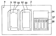
도 2는 테이블(2) 위에 배치된 샘플 플레이트 등을 나타낸 것이다.2 shows a sample plate or the like arranged on the table 2.
2장의 샘플 플레이트(50)가 각각 소정의 위치에 고정되어 재치할 수 있게 되어 있다. 52는 멤브레인으로, 샘플 플레이트(50) 위에 부착되어, 이 분주장치에서 시약이나 샘플이 분주되는 것이다. 멤브레인(52)에 고상화된 시료는, 예를 들면SDS(도데실 황산 나트륨) 폴리아크릴아미드 겔 전기영동이나 그 밖의 크로마토그래피에 의해 일차원 방향으로 분리되어서 전개된 단백질, 펩티드, 당, 지질, 핵산 등의 분자 또는 그들의 혼합물이다.The two
멤브레인(52)에의 시료의 고상화는, 겔 기타의 영동매체에 시료를 전개시킨 후, 멤브레인(52)에 전사함으로써 행할 수 있다.The solidification of the sample to the
이러한 고상화에 사용되는 멤브레인의 재질로서는, PVDF(polyvinylidene difluoride), 니트로셀룰로오스, 나이론(등록상표) 또는 그것의 파생물 등을 들 수 있다.Examples of the material of the membrane used for the solidification include polyvinylidene difluoride (PVDF), nitrocellulose, nylon (registered trademark) or derivatives thereof.
멤브레인(52) 위에 전개해서 고상화된 스폿 내의 물질을 검출하기 위해, 멤브레인(52)에 고상화된 시료성분에 분주소자(10-1∼10-4)로부터 소화액이나 추출액을 분주할 수 있다.In order to detect the substance in the spot solidified on the
또한, 대상분자에 결합하는 프로브가 되는 물질을 분주할 수도도 있다. 그러한 프로브로서는, 대상분자가 항원일 경우에는 항체를 사용한다. 일반적으로는, 대상분자와 특이적으로 반응하는 생체물질을 사용할 수 있다. 또한, 몇개의 항체나 생체물질을 조합해서 사용할 수도 있다.In addition, a substance serving as a probe that binds to a target molecule may be dispensed. As such a probe, an antibody is used when a target molecule is an antigen. In general, a biomaterial that specifically reacts with a target molecule can be used. Moreover, some antibodies and biological substances can also be used in combination.
시약의 분주는, 멤브레인(52) 상의 스폿이 존재하는 영역에만 행하도록 하는 것이 바람직하다. 그것에 의해, 시약의 낭비를 줄이는 것이 가능하다.Dispensing of the reagent is preferably performed only in the region where the spot on the
대상물질을 광학적으로 검출할 수 있게 하려면, 분주하는 시약으로서 대상물질과 특이적으로 반응하는 프로브를 포함하는 1차 시약과, 프로브와 반응한 후의 대상물질을 발색시키는 2차 시약을 사용할 수 있다. 그 경우, 분주소자(10-1∼10-4) 중 어느 하나로부터 우선 1차시약을 분주하고, 그후 1차시약을 분주한 영역 위에 분주소자(10-1∼10-4)의 다른 것으로부터 2차시약을 분주한다. 그러한 2차시약으로서는, 발색시약이나 형광시약을 사용할 수 있다.In order to be able to detect the target material optically, a primary reagent including a probe that specifically reacts with the target material can be used as the reagent to be dispensed, and a secondary reagent that develops the target material after reacting with the probe. In this case, the first reagent is first dispensed from one of the dispensers 10-1 to 10-4, and then from the other of the dispensers 10-1 to 10-4 on the area in which the primary reagent is dispensed. Dispense the secondary reagent. As such a secondary reagent, a coloring reagent or a fluorescent reagent can be used.
또한, 대상분자에 프로브를 반응시킨 후, 그것을 적당한 수단에 의해 검출하 는 방법으로서, 발색시약이나 형광시약을 분주하는 것 이외에, 금속이온을 반응시키거나, 또는 이들 방법을 조합할 수 있다. 그러한 방법으로서는, 금 콜로이드 표지항체를 사용하는 방법이나, 금속 이온에 친화성을 가지는 단백질 등을 Ni2+ 킬레이트 효소 등을 이용하여 형광반응에 도입하는 방법이 있다.As a method of detecting the probe by reacting the target molecule with a suitable means, in addition to dispensing a coloring reagent or a fluorescent reagent, metal ions can be reacted or a combination thereof. As such a method, there is a method of using a gold colloidal label antibody or a method of introducing a protein having affinity for metal ions into a fluorescence reaction using a Ni 2+ chelating enzyme or the like.
복수의 분주소자(10-1∼10-4)가 설치되어 있기 때문에, 테이블(2)에 의해 샘플 플레이트(50) 상의 분주위치를 이동시킴으로써, 분주소자(10-1∼10-4)를 교채하여 복수의 시약을 분주할 수 있다.Since a plurality of distributors 10-1 to 10-4 are provided, the distributors 10-1 to 10-4 are bridged by moving the dispensing position on the
각 샘플 플레이트(50)에는 복수의 마크 b가 설치된다. 그들 마크 b는 샘플 플레이트(50) 위에 부착된 멤브레인(52) 상의 분주위치를 정보로서 작성할 때의 기준이 되는 레퍼런스 포인트이다. 이 예에서는 거의 사각형의 4개의 모퉁이에 레퍼런스 포인트(25b)가 설치되어 있고, 멤브레인(52)의 화상과 함께 그들의 레퍼런스 포인트 b도 스캐너(6)에 의해 받아들인다. 샘플 플레이트(50)의 1개의 모서리는, 샘플 플레이트(50)의 방위를 나타내기 위해서 잘라져 있다.Each
테이블(2) 위에 설치된 영역(54)은, 분주소자(10-1∼10-4)에 의한 분주 테스트를 행하기 위한 테스트 프린트부로서 설정된 영역이다. 거기에도 여과지가 부착되어 있어, 테스트 프린트시의 분주상태를 CCD 카메라(5)로 확인할 수 있도록 되어 있다.The
테이블(2) 위에 설치된 영역(56)은, 분주소자(10-1∼10-4)의 메인티넌스부로서, 스폰지(57)가 설치된다. 분주소자(10-1∼10-4)의 선단에 액이나 오염물이 부착된 경우에, 이 메인티넌스부가 분주소자(10-1∼10-4) 아래로 이동시되어, 그 스폰 지(57)에 의해 분주소자(10-1∼10-4)의 선단에 붙은 액이나 오염물이 없어지도록 되어 있다.The area |
또한, 테이블(2)의 표면에는 테이블(2) 위에 배치되는 샘플 플레이트(50)의 위치의 기준이 되는 베이스 포인트로서 마크 a가 설치되어 있다. 마크 a는, 분주위치를 정보로서 추출하는 경우의 기준이 되는 것이며, 또한 스캐너(6)로 취득한 화상 상의 위치와 테이블(2)의 움직임을 맞추는 기준이 되는 것이다. 헤드(4)에 있어서의 각각의 분주소자(10-1∼10-4)는 같은 구조이다.Moreover, the mark a is provided in the surface of the table 2 as a base point used as a reference | standard of the position of the
미량분주방식에 사용하는 액체 분주장치의 일례는, 위에 서술한 피에조 소자에 의한 분주방식의 것이다. 그러한 액체 분주장치에서는, 선단의 토출부에 연결되는 공간에 충전된 시약을, 피에조 소자를 구비한 구동부에 의해 가압함으로써 그 토출부에서 액체방울을 토출한다. 그 경우, 제어신호의 파라미터는, 피에조 소자에의 인가 전압의 크기, 인가 전압의 상승 시간, 인가 시간, 인가 전압의 하강시간 중에서 적어도 1개를 포함할 수 있다.An example of the liquid dispensing apparatus used for the microdispensing method is the dispensing method by the piezoelectric element described above. In such a liquid dispensing apparatus, droplets are discharged from the discharge portion by pressurizing the reagent filled in the space connected to the discharge portion at the tip end by the driving portion provided with the piezo element. In that case, the parameter of the control signal may include at least one of the magnitude of the voltage applied to the piezoelectric element, the rise time of the applied voltage, the application time, and the fall time of the applied voltage.
이것과 유사의 액체 분주장치로서, 잉크젯 방식의 액체토출장치에서 사용하고 있는 액체토출소자를 구비한 것도 사용할 수 있다.As a liquid dispensing apparatus similar to this, one provided with a liquid discharging element used in an ink jet liquid discharging apparatus can also be used.
미량분주방식에 사용하는 액체 분주장치의 다른 예로서, 실린지 펌프에 의한 분주방식의 장치도 사용할 수 있다. 그 경우, 제어신호의 파라미터는, 실린지 펌프의 플런저의 스트로크, 속도, 가속 중에서 적어도 1개를 포함할 수 있다.As another example of the liquid dispensing apparatus used for the microdispensing system, a dispensing system using a syringe pump can also be used. In that case, the parameter of the control signal may include at least one of the stroke, speed, and acceleration of the plunger of the syringe pump.
분주소자로서, 피에조 소자를 내장한 피에조 칩(10)을 구비한 분주기구의 일례를 도 3을 이용하여 상세하게 설명한다.An example of a dispensing mechanism having a
하단에 토출구를 갖고 상단에 중공침(16)을 가진 액체토출부로서의 피에조 칩(10)이, 나사(29)에 의해, 액체 분주장치의 칩 지지부(31)에 착탈 가능하게 부착되어 있다. 피에조 칩(10)은 나사(29)를 느슨하게 함으로써 제거할 수 있고, 나사(29)를 체결함으로써 고정할 수 있다. 피에조 칩(10)을 착탈하면, 분주위치의 어긋남이 생긴다. 그 때문에, 후술하는 바와 같이, 본 실시예에서는 테이블(2) 상의 베이스 포인트 a를 기준으로 하여 분주위치를 교정한다.The
분주액 용기(20)는 1회용 사용 가능한 것이며, 하단과 상단에 개구를 갖고, 하당 개구가 덮개(15)에 의해 닫혀 내부에 분주액을 수용하는 용기이다. 하단 개구의 덮개(15)은 탄성체 세프탐으로서, 피에조 칩(10)의 중공침(16)에 의해 관통할 수 있고, 또한, 그 관통한 중공침(16)을 분리하면 그 관통구멍을 탄성에 의해 막을 수 있는 탄성부재에 의해 구성되어 있다. 덮개(15)를 구성하는 탄성부재는, 예를 들면 고무이다.The dispensing
용기(20)를 칩(10) 위에 장착하고, 중공침(16)에 의해 하단개구의 덮개(15)를 관통해서 장착한 상태에서, 용기(20)의 상부로부터 에어 도입 헤드(30)를 부착할 수 있도록 되어 있다. 에어 도입 헤드(30)는, 용기(20) 내의 압력을 조정하고, 칩(10)으로부터의 액의 토출량을 조정하는 것이다.The
에어 도입 헤드(30)의 선단부에는 실 부재(32)이 설치된다. 실 부재(32)는 예를 들면 0링이다. 에어 도입 헤드(30)를 용기(20)에 대하여 가압함으로써, 실 부재(32)는 용기(20)의 개구부의 내측면과 접촉해서 용기(20)의 개구부를 기밀로 유지해서 봉지하고, 에어 도입 헤드(30)에 압력제어기구로부터 보내지는 에어에 의해 용기(20) 내의 압력을 제어할 수 있게 된다.The
에어 도입 헤드(30)를 착탈 가능하게 장착하기 위해서 아암 기구를 구비하고 있다. 아암 기구는 아암(33)과 록(36)을 구비하고, 에어 도입 헤드(30)는 아암(33)의 일단부에서 지지되어 있다. 아암(33)은 그것의 기단부가 핀(34)에 의해 액체 분주장치 본체에 회전 가능하게 지지되어 있다. 록(36)은 핀(38)에 의해 아암(33)에 회전 가능하게 지지되고 있어, 기단부에는 낚시바늘(40)이 설치되어 있다. 낚시바늘(40)은 액체 분주장치 본체에 고정된 볼록부(35)과 걸어맞추어, 용기(20)를 칩(10) 위에 장착한 상태에서 록크할 수 있도록 되어 있다.The arm mechanism is provided for attaching the
에어 도입 헤드(30)는 아암(33)에 열린 구멍에 슬라이드 가능하게 삽입되고, 스프링(41)에 의해 에어 도입 헤드(30)를 용기(20)의 방향으로 밀어내도록 가압된다. 에어 도입 헤드(30)의 기단부는 아암부(33)으로부터 돌출하여, 그 부분에 플랜지(45)가 설치됨으로써 에어 유입 헤드(30)가 아암(33)로부터 빠져 나오는 것이 방지되고 있다. 에어 유입 헤드(30)의 기단부는 배관(44)을거쳐서 압력제어기구에 접속되어 있다.The
록(36)을, 핀(38)을 중심으로 낚시바늘(40)이 볼록부(35)과 걸어맞추어지는 방향으로 가압하기 위해서 아암(33)과 록(36) 사이에는 압축 상태의 코일 스프링(42)이 삽입되어 있다.Between the
아암(33)과 액체 분주장치 본체의 사이에는 스프링(43)이 걸려 있으며, 스프링(43)은 아암(33)을 여는 방향(도면에서는 시계 주위의 방향)으로 인장하도록 가압하고 있다.A
도 3의 기구에 있어서, 용기(20)를 장착하는 경우에는, 용기(20)를 칩(10) 위에 두고, 아래쪽으로 눌러 중공침(16)으로 세프탐(15)을 관통하여, 용기(20) 내의 용액에 중공침(16)을 담근다. 에어 도입 헤드(30)는 아암(33)에 지지되어 있기 때문에, 아암(33)을 도면에서 반시계 방향으로 회동시킴으로써, 에어 도입 헤드(30)가 용기(20)의 개구부에 장착되고, 용기(20)와 에어 도입 헤드(30)가 실 부재(32)에 의해 기밀을 유지해서 접속된다. 또 이때, 낚시바늘(40)은 볼록부(35)와 걸어맞추어져 아암(33)이 록크되고, 아암(33)이 열리도록 시계 방향으로 회동하는 것이 방지된다. 에어 도입 헤드(30)는 스프링(41)에 의해 용기(20)의 방향으로 눌리도록 가압되어 있으므로, 아암(33)을 록크한 상태에서 용기(20)와 헤드(30)의 기밀 접속이 유지된다.In the mechanism of FIG. 3, when the
이 상태에서 칩(10)으로부터 액의 토출을 행할 수 있게 된다. 용기(20)를 분리하는 경우에는, 록(36)을 아암(33)의 방향으로 누른다. 록(36)은 핀(38)을 중심으로 도면에서 시계 방향으로 회전하고, 낚시바늘(40)과 볼록부(35)의 걸림이 해제되어, 아암(33)은 스프링(43)의 힘에 의해 도면에서 시계방향으로 회전하며, 에어 도입 헤드(30)가 용기(20)로부터 떨어진다.In this state, the liquid can be discharged from the
이 상태에서는 에어 도입 헤드(30)은 아암 기구와 함께 핀(34)을 중심으로 회동하기 위해서, 에어 도입 헤드(30)과 용기(20)의 사이가 크게 열려, 에어 도입 헤드(30)의 씰재(32)나, 용기(20)의 주변의 청소 등의 메인티넌스가 쉬워진다.In this state, the
또한, 이렇게 아암 기구를 이용하여 에어 도입 헤드(30)를 용기(20)에 대하여 착탈할 수 있게 하면, 용기(20)의 착탈, 및 용기(20)에의 에어 도입 헤드(30)의 착탈을 용이하게 행할 수 있게 된다.In addition, when the
도 1로 되돌아가 CCD 카메라(5)에 관하여 설명한다.1, the
샘플, 시약에 관계 없이, 액상을 사용하는 많은 분석장치의 분야에서는, 분석시에 사용하는 용액의 양을 줄이는 시도가 행해지고 있다.Regardless of samples and reagents, attempts have been made to reduce the amount of solution used in analysis in the field of many analytical devices using liquid phases.
이것은, 귀중한 샘플의 낭비를 줄이하기 위해서나 고가의 시약의 사용량을 줄하기 위해서 뿐만 아니라, 용액 사이의 생화학적인 반응에 있어서는, 용액의 양이 적을수록 반응에 걸리는 시간이 짧기 때문에, 실험의 처리 효율을 높이기 위해서 유효한 방법이기 때문이다.This is not only to reduce the waste of valuable samples or to reduce the amount of expensive reagents used, but also in the biochemical reaction between the solutions, the smaller the amount of the solution, the shorter the time required for the reaction. This is because it is a valid way to increase
미량용액으로 반응을 실행하려면, 샘플 또는 시약을 미량으로 분주하는 분주장치가 필요하다. 미량의 액을 분주하기 위한 방법으로서, 실시예의 피에조 소자 등의 압전소자를 사용한 방법 이외에, 밸브의 개폐에 의한 방법, 용액을 국소적으로 가열해서 생기는 기포를 사용하는 방법 등, 여러가지 것이 실용화되고 있다.In order to carry out the reaction with a trace solution, a dispensing device for dispensing a sample or reagent in a small amount is required. As a method for dispensing a small amount of liquid, various methods, such as a method of opening and closing a valve and a method of using a bubble generated by locally heating a solution, have been put to practical use in addition to the method using piezoelectric elements such as the piezo element of the embodiment. .
미량의 액체를 원하는 위치에 분주할 때는, 압전소자이면 소자에의 전압을 가하는 방법, 밸브를 사용하는 것이라면 개폐 시간 등, 다양한 파라미터의 미묘한 제어가 요구된다. 이들 파라미터를 최적화하기 위해, 또한, 수많은 위치에 분주할 때에는 분주시간도 길어지기 때문에, 분주하는 액체방울의 형상을 모니터해서 분주기가 놓어져 있는 환경의 변화나 압전소자의 시간에 따른 변화에 대응하기 위해서, 분주소자 선단부에 형성되는 액체방울의 화상을 촬상장치에서 받아들여서 모니터 하는 것이 바람직하다. CCD 카메라는 그러한 촬상장치의 일례이다.When dispensing a small amount of liquid at a desired position, delicate control of various parameters such as a method of applying a voltage to the element in the case of a piezoelectric element and an opening and closing time in the case of using a valve is required. In order to optimize these parameters, the dispensing time also takes longer when dispensing at a large number of positions, so that the shape of the dispensing droplet is monitored to cope with changes in the environment in which the dispenser is placed or changes over time of the piezoelectric element. In order to do this, it is preferable to take an image of a liquid droplet formed in the tip end portion of the addressing device and monitor the image. The CCD camera is an example of such an imaging device.
분주상태를 모니터하기 위한 CCD 카메라(5)를 수평방향으로부터 각도를 두어 비스듬하게 위쪽에게 배치하도록 함으로써, 가동 테이블(2)과 간섭하지 않고 가동 테이블(2)의 이동 범위 내에 설치 할 수 있어, 분주장치가 소형이 된다.By arranging the
분주소자 선단부를 사이에 끼워 CCD 카메라(5)와는 반대측의 위치에 광원을 배치해도 되며, 그 경우, 그 광원은 그것을 발생하는 빛이 대상물인 샘플 플레이트(50)의 표면에서 반사해 분주소자 선단부를 경유해서 CCD 카메라(5)에 입사하는 방향을 향할 수 있다. 이러한 광원을 설치함으로써, 분주소자 선단부에 형성되는 샘플 또는 시약의 액체를 모니터하는 경우에는, 그 방울의 화상을 투과광으로 촬영 할 수 있게 되어, 보다 선명한 화상을 얻어서 정확한 모니터를 행할 수 있게 된다. 또한, 이 광원을 분주의 타이밍과 동기시켜서 점등함으로써, 액체방울을 정지 화상과 같이 받아들일 수 있다.The light source may be disposed at a position opposite to the
CCD 카메라(5)은 분주소자 선단부의 화상과 함께 분주소자의 아래쪽에 있는 샘플 플레이트 표면의 화상도 촬상하도록 설정해 둘 수 있다. 그 경우에는, 분주소자 선단부의 모니터와 함께, 샘플 플레이트 표면의 상태도 모니터할 수 있게 되어, 보다 많은 정보를 얻을 수 있다. 예를 들면, 목적으로 하는 위치에 정확하게 샘플이나 시약을 분주할 수 있는지 아닌지를 확인할 수 있게 되거나, 또한 예를 들면 샘플이나 시약이 분주되는 대상물이 막인 경우, 분주 전후의 막의 상태를 관찰하거나, 반응중의 막 상태의 시간에 따른 변화의 관찰을 하는 것도 가능하게 된다.The
이 분주장치의 용도로서, 예를 들면 PVDF(polyvinylidene difluoride)막과 같은 고상에 시약을 분주하는 것을 들 수 있다. PVDF 막에는, 크로마토그래피에 의해 전개한 스폿이 전사되어 있으며, 그 스폿을 발색 시키기 위해서, 시약이 분주된 다. 그와 같은 고상으로서 사용할 수 있는 것으로서는, PVDF막 이외에, 니트로 셀룰로오스나 나이론(등록상표) 등도 사용할 수 있다.As the use of this dispensing device, for example, dispensing of a reagent on a solid phase such as a polyvinylidene difluoride (PVDF) membrane is possible. The spot developed by chromatography is transferred to the PVDF membrane, and a reagent is dispensed in order to develop the spot. As what can be used as such a solid phase, nitrocellulose, a nylon (trademark), etc. can also be used besides a PVDF film.
도 4는 도 1의 장치의 기능을 블록도로서 나타낸 것이다.4 shows in block diagram the function of the apparatus of FIG.
60은 스캐너 등의 화상판독장치(6)가 판독한 화상을 표시하는 모니터부이다. 분주위치 지정부(62)는 모니터부(60)에 표시된 멤브레인 등의 대상물(50)의 화상에 기초하여 대상물(50) 상의 분주위치를 지정하기 위한 것인다. 분주제어부(64)는 분주위치 지정부(62)가 지정한 대상물 위의 분주위치가 분주소자(10)의 분주소자의 아래쪽으로 오도록 대상물과 분주소자의 상대적 위치결정을 행하고, 분주소자(10)에 의한 분주동작을 제어하는 것이다. 분주소자(10)가 피에조 소자를 구비한 것인 경우에는, 분주제어부(64)는 압력제어부(7)에 의해 분주소자(10) 내의 압력을 조정하고, 분주제어 유닛(66)에 의해 피에조 소자에의 전압인가를 제어해서 피에조 소자로부터 액을 토출한다.60 is a monitor unit which displays an image read by the
분주위치정보 작성부(68)는, 분주위치 지정부(62)이 지정하여 분주동작이 행해진 대상물(50) 상의 분주위치에 관한 분주위치 정보를 작성하는 것이다. 분주위치정보 작성부(68)는 작성된 분주위치 정보를 외부로 출력할 수 있다.The dispensing position
대상물(50)에는 도 2에 나타낸 것과 같이 대상물 내의 위치의 기준이 되는 레퍼런스 포인트 b을 복수개 설치해 두고, 화상판독장치(6)가 대상물(50)의 화상과 함께 레퍼런스 포인트 b의 화상도 판독하도록 한다. 이에 따라, 분석 위치정보 작성부(68)은 분석 위치지정부(62)가 지정한 대상물(50) 상의 위치를 복수의 레퍼런스 포인트 b을 기초로 해서 작성할 수 있고, 대상물을 일단 분리하여, 다시 테이블 (2)에 부착한 경우에도 스캐너(6)로 화상을 취득하면, 레퍼런스 포인트 b를 기초로 정확하게 위치결정할 수 있게 된다. 또한, 대상물(50)을 분석 장치 등에 이동시킨 경우에도, 그 레퍼런스 포인트 b를 기초로 해서 그 분주위치 정보로부터 대상물(50) 내에서의 분주 위치에 정확하게 위치결정할 수 있게 된다.As shown in Fig. 2, the
대상물을 지지하는 테이블(2)은 테이블 구동기구(65)에 의해 구동되어 평면 내에서 이동하고, 분주제어부(64)에 의해 지시된 소정의 위치에 위치결정된다. 테이블(2) 위에는, 기준이 되는 베이스 포인트 a를 복수개 설치해 두고, 화상판독장치(6)가 대상물(50)의 화상과 함께 베이스 포인트 a의 화상도 판독하도록 하고, 분석 위치정보 작성부(68)는 대상물(50) 상의 위치를 복수의 베이스 포인트 a를 기초로 해서 작성할 수 있는 것으로 할 수 있다. 이에 따라, 대상물(50) 내에서의 분주위치 정보를 베이스 포인트 a를 기초로 해서 정확하게 정할 수 있게 된다.The table 2 supporting the object is driven by the
샘플 또는 시약을 적하하는 분주소자(10)는 착탈 가능하게 되어 있어, 분주소자(10)의 분주위치를 교정하기 위한 교정부(72)를 구비하고 있다. 교정부(72)는, 분주소자(10)에 의해 테이블(2) 상의 소정의 위치에 분주를 행했을 때의 화상판독장치(6)에 의한 판독 화상에 기초하여 분주위치를 검출하고, 동시에 판독한 테이블 상의 기준이 되는 베이스 포인트를 기초로 하여 분주위치의 교정을 행한다. 교정을 위한 분주는, 예를 들면 도 2에 나타낸 테이블(2) 상의 시약 등을 분주하면 발색하는 것과 같은 멤브레인(53)에 의한 3개의 점으로 나타낸 것과 같은, 미리 정해진 복수의 위치에서 행한다. 이 교정은, 분주소자를 장착할 때마다 행한다.The
상기의 실시예는 분주장치에 본 발명을 적용한 경우를 예로 들어 설명하고 있지만, 구하려고 하는 위치 정보는 분주위치의 정보에 한정되지 않고, 멤브레인이나 영동매체 등의 화상을 화상판독장치에서 읽어내고, 그 화상 중의 스폿 등 검출된 위치의 정보를 작성하는 경우에도 본 발명을 마찬가지로 적용할 수 있다.Although the above embodiment has been described taking the case where the present invention is applied to the dispensing apparatus as an example, the positional information to be obtained is not limited to the dispensing position information, and images such as a membrane or a moving medium are read by the image reading apparatus, The present invention can be similarly applied to the case of creating information on a detected position such as a spot in the image.
제 5 국면의 분주장치의 일 실시예에 관하여 설명한다.An embodiment of the dispensing apparatus of the fifth aspect will be described.
도 5는 동 국면의 분주장치의 일 실시예를 나타낸 것이다. 시약(또는 샘플)을 분주하는 분주기구(102)는, 그 하단에 노즐을 가지고, 미량의 액을 적하할 수 있게 되어 있다. 분주기구(102)의 하부에는 가동 테이블로서의 X-Y 테이블(104)이 배치되고 있고, X-Y 테이블(104) 위에는 시약이 분주되는 대상물이 재치된다. X-Y 테이블(104)은, 대상물을 지지하는 면을 도면에서 지면 수직방향(Y 방향)으로 구동하는 Y 구동기구(104Y)와, Y 구동기구(104Y)에 부착되고, 대상물을 지지하는 면을 도면에서 횡 방향(X 방향)으로 구동하는 X 구동기구(104X)를 구비하고 있다. X-Y 테이블(104)의 대상물 지지면은 그 Y 구동기구(104Y)와 X 구동기구(104X)에 의해 수평면 내에서 Y 방향과 X 방향으로 이동하고, 지지면 위에 재치된 대상물을 분주기구(102)의 노즐의 아래쪽에 위치결정한다.5 shows an embodiment of the dispensing apparatus of the same phase. The
촬상장치(106)는 예를 들면 CCD 카메라이며, 촬상장치(106)의 수광 축(110)이 수평방향으로부터 각도 θ를 가지도록, 촬상장치(106)는 분주기구(102)의 노즐 선단부의 비스듬하게 위쪽에 부착되어 있다. 촬상장치(106)는 분주기구(102)의 노즐 선단부에 형성되는 액체방울의 화상을 취하도록 설정되어 있다.The
촬상장치(106)가 부착되어 있는 위치의 평면 상의 위치는, X-Y 테이블(104)의 이동 범위 내에 있지만, X-Y 테이블(104)이 그 이동 범위 내에서 이동해도 촬상 장치(106)와 접촉하지 않도록, 촬상장치(106)의 부착 위치는 X-Y 테이블(104)의 위쪽으로 설정되어 있다.Although the position on the plane of the position where the
촬상장치(106)의 수광 축(110)과 수평면이 이루는 각도 θ에는 적당한 범위가 존재한다. θ는 적어도 촬상장치(106)가 X-Y 테이블(104)과 간섭하지 않을 정도의 크기를 가지고, 분주기구(102)의 노즐 선단에 형성되는 샘플 또는 시약의 액체방울의 화상을 받아들이는데도 지장이 없는 범위로 설정된다. 그러한 각도 θ로서는, 15∼45도 정도가 적당하다.An appropriate range exists at an angle θ formed between the
노즐 선단을 사이에 끼워서 촬상장치(106)와 반대측의 위치에서, X-Y 테이블(104)의 위쪽에는, 광원(108)이 부착되어 있어, 촬상장치(106)가 투과광으로 촬상할 수 있게 되어 있다.A
도 6에 나타낸 것과 같이, 광원(108)로부터 발생한 빛(112)이 X-Y 테이블(104) 상의 대상물(114)의 표면에서 반사하고, 분주기구(102)의 노즐(120)의 선단부에 형성된 액체방울(122)을 경유하여, 촬상장치(106)의 수광 축(110)을 따라 촬상장치(106)에 입사하도록, 광원(108), 촬상장치(106), 노즐(120) 및 대상물(114)의 상대적인 위치 관계가 설정되어 있다.As shown in FIG. 6, the light 112 generated from the
촬상장치(106)의 피사계 심도는, 노즐 선단부의 액체방울(122) 및 그 아래에 있는 대상물(114)의 표면에도 초점이 맞도록 설정되어 있는 것이 바람직하다. 이에 따라, 노즐 선단부의 액체방율(122)의 상태와, 대상물(114)의 표면의 상태를 동시에 화상으로서 받아들여 모니터할 수 있다.It is preferable that the depth of field of the
이 분주장치의 용도로서, 예를 들면 PVDF(polyvinylidene difluoride)막과 같은 고상으로 시약을 분주하는 것을 들 수 있다. PVDF 막에는, 박층 크로마토그래피에 의해 전개한 스폿이 전사되고 있으며, 그 스폿을 발색시키기 위해서, 시약이 분주된다. 그러한 고상으로서 사용할 수 있는 것으로서는, PVDF막 이외에, 니트로셀룰로오스나 나이론(등록상표) 등도 사용할 수 있다.As the use of the dispensing device, for example, dispensing the reagent into a solid phase such as a polyvinylidene difluoride (PVDF) film. The spot developed by thin layer chromatography is transferred to the PVDF membrane, and a reagent is dispensed in order to develop the spot. As the solid phase, nitrocellulose, nylon (registered trademark) and the like can be used in addition to the PVDF film.
X-Y 테이블(104)을 이동시켜서 다수의 분주위치에서 노즐 선단으로부터 시약이나 샘플의 분주를 반복한다. 그 때, 노즐 선단으로부터 적하하는 액체방울의 형상을 모니터할 때에, 노즐(120)로부터의 액체방울(122)의 적하 시작으로부터 촬상장치(106)가 화상을 받아들이는 타이밍을 일정하게 함으로써, 그들 액체방울을 같은 타이밍의 화상으로서 처리 할 수 있게 된다.The X-Y table 104 is moved to repeat dispensing of reagents or samples from the nozzle tip at multiple dispensing positions. At that time, when monitoring the shape of the droplet dropped from the tip of the nozzle, the timing at which the
그러한 화상의 받아들임을 실현하는 1가지 방법으로서, 광원(108)으로서 스트로보를 사용하여, 촬상장치(106)는 연속해서 촬상하도록 하고, 노즐(120)로부터의 적하 시작으로부터 스트로보를 점등시킬 때까지의 시간을 일정하게 하는 방법을 들 수 있다. 이에 따라 다수의 액체방울을 같은 타이밍으로 촬상해서 액체방울의 형상을 모니터하는 것이 용이해진다. 이러한 액체방울 형상의 모니터는, 다수 반복되는 액체방울의 형상이 일정하게 되도록, 샘플이나 시약을 분주하는 분주기구의 피에조 소자에의 인가 전압이나 밸브의 개폐 등을 제어하는데에도 이용할 수 있다.As one method of realizing such an image reception, using the strobe as the
광원(108)은 스트로보에 한정되지 않고, 연속해서 발광하는 것이어도 되며, 그 경우에는 촬상장치(106)쪽에서 액체방울(122) 적하 시작으로부터 일정한 시간에 화상을 받아들이도록 제어를 행하면 된다.The
도 7은 제 6 국면의 일 실시예의 분주장치를 개략적으로 나타낸 것이다. 201 은 피에조 칩에 의한 분주기구로서, 나중에 나타낸 도 8에 도시되어 있는 것과 같은 피에조 칩이 설치되어 있다. 203은 그 피에조 칩에서 토출된 액체방울로서, 분주기구(201)의 하부에 지지된 용기나 플레이트 등의 타깃(205)에 분주된다. 분주기구(201)의 선단에 어떤 토출부의 화상을 받아들여서 모니터하기 위해서 촬상장치로서 CCD 카메라(204)가 배치되어 있다. CCD 카메라(204)는 토출부의 상태와 함께, 토출되는 액체방울(203)도 동시에 촬영할 수 있다. 촬영장치로서는 CCD 카메라에 한정되지 않고, 다른 카메라를 이용하여도 된다.7 schematically shows a dispensing apparatus of an embodiment of a sixth aspect. 201 is a dispensing mechanism using piezo chips, in which piezo chips as shown in FIG. 8 shown later are provided. 203 is a droplet discharged from the piezo chip, and is dispensed to a
CCD 카메라(204)는 분주기구(1)의 선단부를 수평방향으로부터 촬상한다. 수평으로부터 경사를 갖고 비스듬하게 위방향으로부터 촬상해도 좋지만, 토출부의 선단의 상태를 더 정확하게 모니터하려면, 수평방향으로부터 촬상하는 것이 바람직하다.The
분주기구(201)의 선단부의 화상을 보다 정확하게 받아들이기 위해서, 본 실시예에서는 투과광으로 촬영할 수 있도록, CCD 카메라(204)의 광축 상에는, 분주기구(1)의 선단부를 끼워서 CCD 카메라(204)와 반대측에 광원(202)이 배치되어 있다. 광원(202)으로서는 시간적으로 연속된 빛을 발광하는 것이어도 되지만, 본 실시예로서는 스트로보를 사용한다. 스트로보의 경우, 액체방울(203)이 분주기구(201)로부터 토출되는 타이밍과 동기해서 발광하도록 설정할 수 있고, 그 경우에는 카메라(204)를 연속해서 작동시키고 있는 경우에도, 스트로보(202)가 발광한 경우에만 선명한 화상이 받아들여진다. 그 선명한 화상은, 순차적으로 토출되는 액체방울(203)의 화상이 같은 타이밍으로 받아들여진 것이기 때문에, 마치 정지 화상과 같은 정보를 얻을 수 있다. 그 때문에, 액체방울(203)의 상태를 모니터하는 것이 적합하다.In order to capture the image of the distal end of the
206은 분주제어 유닛으로서, 분주기구(201)의 피에조 소자에 전압을 인가함으로써 토출을 행한다. 또한, 스트로보(202)의 발광하는 타이밍은, 분주제어 유닛(206)에 의해 분주기구(201)의 피에조 소자에의 전압인가의 타이밍에 동기시켜 분주기구(201)로부터의 액체방울 토출의 일정시간 후에 발광하도록 제어된다.206 denotes a dispensing control unit which discharges by applying a voltage to the piezo element of the
208은 압력제어기구이며, 분주기구(201)의 액체를 충전하는 공간인 저장소에 충전된 샘플이나 시약 등의 토출액이 항상 일정한 압력을 유지하도록 유지하는 것이다. 압력제어기구(208)는, 본 발명에 있어서 토출동작 시작전의 토출부 선단의 액체 표면을 조정하기 위해서도 사용된다.Denoted at 208 is a pressure control mechanism, which maintains a constant pressure of a discharge liquid such as a sample or a reagent filled in a reservoir, which is a space for filling a liquid of the
207은 제어 컴퓨터이며, 분주제어 유닛(206)을 제어해서 분주동작을 제어하는 동시에, CCD 카메라(204)가 촬상한 화상을 기억하는 기억장치를 구비하고, 분주기구(201)에 있어서의 피에조 칩의 저장소에 액체를 충전하기 전의 토출부의 화상으로 기억장치에 기억된 화상과 저장소에 액체를 충전한 후의 화상을 비교하여, 액체가 토출부에서 나타난 후, 액체 충전전의 화상과의 차이가 없어질 때까지 후퇴하도록 압력제어기구(208)를 제어하는 제어장치의 기능도 실현하고 있다.
도 8은 분주기구(201)에 있어서의 피에조 칩의 일례를 개략적으로 나타낸 것이다.8 schematically shows an example of a piezo chip in the
피에조 칩는, 저장소(232)로부터 선단의 토출부(230)의 구멍에 연결되는 유로를 구비하고 있으며, 저장소(232) 또는 유로에 있는 액체를, 피에조 소자를 구비 한 구동부(234)에 의해 가압함으로써 토출부(230)로부터 액을 토출 한다. 피에조 소자의 구동은, 분주제어 유닛(6)에 의해 제어된다. 저장소(232)의 샘플이나 시약이 감소한 경우에도 일정한 압력상태를 유지하도록, 저장소(232)에는 압력제어기구(208)가 접속되어 있다.The piezo chip has a flow path connected to the hole of the discharging
분주제어 유닛(206)이 피에조 소자의 구동을 제어하는 파라미터는, 피에조 소자에의 인가 전압의 크기, 인가 전압 상승 시간, 인가 시간, 인가 전압 하강시간의 모두, 또는 그 중에서 적어도 1개이다.The parameter for controlling the driving of the piezo element by the frequency dividing
도 9에 의해, 본 실시예에서 분주동작 시작전의 토출부 선단부의 액체 표면상태를 조정하는 동작을 설명한다. 본 실시예는 제어 컴퓨터(7)에 의해 자동적으로 조정을 행하는 경우를 설명하고 있지만, 이 동작을 토출부 선단부의 화상을 보면서 매뉴얼로 행할 수도 있다.9, the operation of adjusting the liquid surface state of the distal end of the discharging portion before the dispensing operation is started in the present embodiment. Although the present embodiment has described the case where adjustment is automatically performed by the
분주를 시작하기 전에, 우선 용액 충전을 실행한다. 피에조 칩 선단은 CCD 카메라(204)의 화상을 받아들이는 것으로 확인할 수 있다.Before starting dispensing, first fill the solution. The piezo chip tip can be confirmed by receiving the image of the
제어 컴퓨터(7)에 의해 피에조 칩에의 용액 충전을 지시하면, 제어 컴퓨터(207)는 우선 CCD 카메라(204)로 충전전의 피에조 칩 선단의 화상을 취득해 유지한다. 이 화상을 화상 (a)라고 한다.When the
다음에, 제어 컴퓨터(207)는, 압력제어기구(208)을 제어해 용액을 가압해서 피에조 칩 선단 방향으로 밀어낸다. 이때, 제어 컴퓨터(7)는 CCD 카메라(204)를 이용하여 피에조 칩 선단의 화상을 정기적으로 받아들여, 먼저 받아들인 충전전의 화상 (a)과의 차이를 취한다. 그 차이에 변화가 있으면 용액이 피에조 칩 선단에서 여분으로 나가고 있는 것이 되므로, 그 상태를 감지하면, 압력제어에 피드백을 걸어 간다. 이 사이도 제어 컴퓨터(207)는 CCD 카메라(204)를 이용하여 피에조 칩 선단의 화상을 정기적으로 받아들이고 있으며, 먼저 취한 충전전의 화상 (a)와의 차이를 치하는 동작을 계속하고 있다. 압력제어에 정기적으로 피드백을 걸어가, 여분 액량이 없어진 것을 화상의 차이로부터 감지하는 것으로 피드백을 멈추고, 그 상태를 유지한다.Next, the
도 10은 제 7 국면의 일 실시예의 방법이 적용되는 장치를 개략적으로 나타낸 것이며, 피에조 방식의 분주장치를 사용하여, 액체방울의 크기를 자동적으로 구하고, 일정하게 하는 제어도 자동적으로 행하는 경우를 나타낸 것이다.Fig. 10 schematically shows a device to which the method of the embodiment of the seventh aspect is applied, and shows a case where the size of a liquid droplet is automatically obtained and the control to make a constant is automatically performed using a piezo system dispensing apparatus. will be.
피에조 칩(302)으로부터 토출되는 액체방울(306)의 화상을 받아들이기 위해서, 촬상장치로서, 피에조 칩(302)으로부터 토출되는 액체방울(6)을 향한 CCD 카메라(320)가 설치되어 있다. 322는 CCD 카메라(320)가 받아들인 화상을 기억하는 화상기억부이다. CCD 카메라(320)에 의한 화상의 받아들임은, 액체방울(6)이 토출되는 타이밍과 동기시키거나 또는 비동기로 받아들인다.In order to receive the image of the
324는 화상처리부이며, 화상처리부(324)는 화상기억부(322)에 기억되어 있는 화상을 2치화나 윤곽추출 등의 화상처리를 실시해서 그 액체방울의 직경이나 반경 등의 크기를 구하고, 분주량을 계산한다. 화상처리부(324)가 화상처리하는 액체방울의 화상은, CCD 카메라(320)에서 액체방울의 토출과 동기시켜 받아들인 화상의 경우에는, 각각의 액체방울에 대해서 토출로부터 동일한 시간에서의 화상이다. 비동기로 받아들인 경우에는, 하나의 화상에 대하여 CCD 카메라(320)에 의해 시계열 로 복수의 화상이 받아들이지만, 그 중에서 각 액체방울에 대해서 같은 장소를 통과하는 액체방울의 화상을 채용해서 화상처리부(324)에서 화상처리한다.324 is an image processing unit, and the
326은 화상처리된 액체방울의 화상을 표시하는 화상처리부이다. 또한, 화상처리부(324)에서 화상처리되어 구해진 분주량은 피에조 분주제어부(304a)로 보내진다. 피에조 분주제어부(304a)에서는 다음으로 토출되는 분주량(액체방울(6)의 크기)이 미리 설정된 설정값과 같아지도록 피에조 칩(302)의 구동을 제어해 간다.326 is an image processing unit which displays an image of droplets which have been image processed. In addition, the dispensing amount obtained by image processing in the
피에조 칩(302)으로서는, 예를 들면 도 11에 나타낸 것과 같이, 선단의 토출부(330)의 구멍에 연결되는 액체 저장소(332)를, 피에조 소자를 구비한 구동부(334)에 의해 가압함으로써 토출부(330)에서 액을 토출한다. 액 저장소(332)의 샘플이나 시약이 감소온 경우에도 일정한 압력상태를 유지하도록, 액체 저장소(332에)는 가압부(도시 생략)가 접속되어 있다.As the
피에조 분주제어부(304a)가 피에조 칩(2)의 구동을 제어하는 파라미터는, 도 12에 나타낸 것과 같이, 피에조 소자에의 인가 전압의 크기 V0, 인가 전압 상승 시간 t1, 인가 시간 t2, 인가 전압 하강시간 t3의 모두, 또는 그중에서 적어도 1개이다.As shown in FIG. 12, the parameters of the
도 13에 본 실시예의 동작을 정리해서 나타낸다.13 summarizes the operation of this embodiment.
미리 설정된 피에조 칩 제어 파라미터로 피에조 칩(302)의 구동을 제어하고, 액체방울(6)을 토출한다. 그 액체방울(306)의 화상을 CCD 카메라(320)가 액체방울의 토출과 동기해서 또는 비동기로 받아들이고, 화상기억부(322)에 기억한다. 화상 처리부(324)는 화상기억부(322)에 기억되어 있는 화상을 2치화나 윤곽추출 등의 화상처리를 실시해서 그 액체방울의 직경이나 반경 등의 크기를 구하고, 분주량을 계산한다. 피에조 분주제어부(304a)는 그 분주량이 소정의 값인 경우에는, 피에조 칩 제어 파라미터를 변경하지 않고, 피에조 칩(302)의 구동을 반복해 간다. 그러나, 그 분주량이 소정의 값이 아닌 경우에는, 피에조 칩 제어 파라미터를 변경하고, 피에조 분주제어부(304a)는 다음부터 토출되는 분주량이 소정의 값과 같아지도록 피에조 칩(302)의 구동을 제어한다.The driving of the
도 14는 다른 실시예의 방법이 적용되는 장치를 개략적으로 나타낸 것이며, 실린지 펌프에 의한 분주장치를 사용하여, 액체방울의 크기를 자동적으로 구하고, 일정하게 하는 제어도 자동적으로 행하는 경우를 나타낸 것이다.Fig. 14 schematically shows a device to which the method of another embodiment is applied, and shows a case where the size of a liquid droplet is automatically obtained and the control to make it constant is also performed automatically using a dispensing apparatus by a syringe pump.
실린지 펌프(310)에 연결되는 프로브(312)로부터의 액체방울(6)의 토출을, 실린지 펌프(310)를 작동시키는 모터(314)를 실린지 분주제어부(318a)에 의해 제어해서 구동함으로써 행한다. 프로브(312)의 선단에는 디스포저블 칩(316)이 설치된다.The syringe
액체방울(306)의 화상을 받아들이는 CCD 카메라(320), 화상기억부(322), 화상처리부(324), 및 화상표시부(326)는 도 10에 도시된 것과 같다.The
실린지 분주제어부(318a)는, 화상처리부(324)로부터 액체방울(306)의 직경이나 반경 등의 액체방울의 크기에 관한 데이터를 받아들이고, 다음부터 토출되는 액체방울(306)의 크기가 미리 설정된 설정값과 같아지도록 모터(314)의 구동을 제어해 간다.The syringe
실린지 분주제어부(318a)가 모터(314)의 구동을 제어하는 파라미터는, 플런저의 스트로크, 속도, 가속도의 모두 또는 그 중의 적어도 1개이다.The parameter that the syringe frequency
도 15에 나타낸 것과 같이, 실린지 방식으로 수백 nL∼수 μL의 분주량의 액체방울(306)을 용기(340)나 플레이트(342)로 분주할 경우에는, 디스포저블 칩(316)의 선단(디스포저블 칩(316)을 사용하지 않는 경우에는 프로브(312)의 선단)에 액체방울(306)이 구슬 형태로 매달리므로, 그 상태의 액체방울(6)을 CCD 카메라(320)에 의해 화상으로서 파악하고, 화상처리부(322)에서, 2치화나 윤곽추출 등의 화상처리를 실시하여, 액체방울의 직경 또는 반경을 구하여, 분주량을 계산한다. 실린지 분주제어부(318a)는, 모터(14)의 구동을 제어할 때, 요청된 액체방울(306)의 크기에 해당하는 액량이 원하는 분주량보다 많으면 플런저를 되돌리고, 부족하면 플런저를 가압함으로써, 분주량을 실시간으로 제어하여, 프로브 또는 디스포저블 칩의 액체방울(306)을 용기(340) 또는 플레이트(342)에 분주한다.As shown in FIG. 15, when dispensing the
본 발명을 실린지 펌프에 의한 분주방식에 적용하는 경우, 칩(316)으로서 디스포저블의 칩이며 칩 안에 필터나 담체를 지지하고 있는 칩을 이용하여 분주하는 경우에도 완전히 동일하게 적용할 수 있다.When the present invention is applied to a dispensing method using a syringe pump, the
본 발명의 액체 분주장치는, 예를 들면, 멤브레인 위에 전개해서 고상화된 물질을 질량분석 등의 시료로 하기 때문에 멤브레인 위에 시약 등을 분주하기 위한 방법 및 장치 등으로서 이용할 수 있다.The liquid dispensing apparatus of the present invention can be used as a method and apparatus for dispensing a reagent or the like on a membrane because, for example, a substance which has been developed on the membrane and solidified is a sample such as mass spectrometry.
Claims (29)
Applications Claiming Priority (12)
| Application Number | Priority Date | Filing Date | Title |
|---|---|---|---|
| JPJP-P-2002-00282513 | 2002-09-27 | ||
| JP2002282513 | 2002-09-27 | ||
| JP2002324237 | 2002-11-07 | ||
| JPJP-P-2002-00324237 | 2002-11-07 | ||
| JP2002326681 | 2002-11-11 | ||
| JPJP-P-2002-00326681 | 2002-11-11 | ||
| JPJP-P-2003-00161484 | 2003-06-06 | ||
| JPJP-P-2003-00161482 | 2003-06-06 | ||
| JP2003161483A JP4438323B2 (en) | 2003-06-06 | 2003-06-06 | Liquid dispensing device |
| JP2003161484A JP4483205B2 (en) | 2003-06-06 | 2003-06-06 | Position information reader and sample plate |
| JPJP-P-2003-00161483 | 2003-06-06 | ||
| JP2003161482A JP4385655B2 (en) | 2003-06-06 | 2003-06-06 | Liquid dispensing device |
Related Child Applications (1)
| Application Number | Title | Priority Date | Filing Date |
|---|---|---|---|
| KR1020067015245A Division KR100646279B1 (en) | 2002-09-27 | 2003-09-29 | Liquid portioning method and device |
Publications (2)
| Publication Number | Publication Date |
|---|---|
| KR20050054934A KR20050054934A (en) | 2005-06-10 |
| KR100681237B1 true KR100681237B1 (en) | 2007-02-09 |
Family
ID=32111148
Family Applications (2)
| Application Number | Title | Priority Date | Filing Date |
|---|---|---|---|
| KR1020057004221A KR100681237B1 (en) | 2002-09-27 | 2003-09-29 | Liquid portioning method and device |
| KR1020067015245A KR100646279B1 (en) | 2002-09-27 | 2003-09-29 | Liquid portioning method and device |
Family Applications After (1)
| Application Number | Title | Priority Date | Filing Date |
|---|---|---|---|
| KR1020067015245A KR100646279B1 (en) | 2002-09-27 | 2003-09-29 | Liquid portioning method and device |
Country Status (6)
| Country | Link |
|---|---|
| US (1) | US7823535B2 (en) |
| EP (1) | EP1548448A4 (en) |
| KR (2) | KR100681237B1 (en) |
| CN (1) | CN1685238A (en) |
| AU (1) | AU2003266690A1 (en) |
| WO (1) | WO2004036228A1 (en) |
Families Citing this family (65)
| Publication number | Priority date | Publication date | Assignee | Title |
|---|---|---|---|---|
| JP4183577B2 (en) * | 2003-07-25 | 2008-11-19 | 武蔵エンジニアリング株式会社 | Droplet adjustment method, droplet discharge method and apparatus |
| KR101026935B1 (en) * | 2003-12-10 | 2011-04-04 | 엘지디스플레이 주식회사 | Apparatus for aligning dispenser and method thereof |
| JP4748503B2 (en) * | 2004-03-23 | 2011-08-17 | 大日本スクリーン製造株式会社 | Processing equipment |
| US20050257738A1 (en) * | 2004-05-21 | 2005-11-24 | Semiconductor Energy Laboratory Co., Ltd. | Manufacturing apparatus of semiconductor device and pattern-forming method |
| TWI356036B (en) * | 2004-06-09 | 2012-01-11 | Smithkline Beecham Corp | Apparatus and method for pharmaceutical production |
| US20060002594A1 (en) * | 2004-06-09 | 2006-01-05 | Clarke Allan J | Method for producing a pharmaceutical product |
| US8101244B2 (en) * | 2004-06-09 | 2012-01-24 | Smithkline Beecham Corporation | Apparatus and method for producing or processing a product or sample |
| JP2006126013A (en) * | 2004-10-28 | 2006-05-18 | Shimadzu Corp | Proteome analyzer |
| JP2006167000A (en) * | 2004-12-13 | 2006-06-29 | Micronics Kk | Eyedropper and nozzle tip |
| US7749553B2 (en) * | 2005-01-31 | 2010-07-06 | Boston Scientific Scimed, Inc. | Method and system for coating a medical device using optical drop volume verification |
| US8263414B2 (en) * | 2005-05-23 | 2012-09-11 | Siemens Healthcare Diagnostics Inc. | Dispensing of a diagnostic liquid onto a diagnostic reagent |
| WO2007063459A1 (en) * | 2005-11-29 | 2007-06-07 | Koninklijke Philips Electronics N.V. | Ink jet device and method for producing a biological assay substrate by releasing a plurality of substances onto the substrate |
| WO2007119499A1 (en) * | 2006-04-14 | 2007-10-25 | Inter-University Research Institute Corporation National Institutes Of Natural Sciences | Method of preparing mass spectrometry sample |
| EP2063265B1 (en) * | 2006-09-28 | 2022-12-14 | Shimadzu Corporation | Method of preparing sample for matrix-assisted laser desorption ionization mass spectrometry and matrix-assisted laser desorption ionization mass spectrometry |
| WO2008042960A2 (en) * | 2006-10-03 | 2008-04-10 | Kalypsys, Inc. | Droplet detection system |
| ATE468734T1 (en) * | 2007-03-23 | 2010-06-15 | Siemens Ag | DEVICE AND METHOD FOR COATING A COMPONENT WITH ADJUSTING DEVICE |
| EP2058135A1 (en) * | 2007-11-07 | 2009-05-13 | Koninklijke Philips Electronics N.V. | Printer device and method for producing biological test arrays |
| US9602777B2 (en) | 2008-04-25 | 2017-03-21 | Roche Diagnostics Hematology, Inc. | Systems and methods for analyzing body fluids |
| JP2012515931A (en) | 2008-04-25 | 2012-07-12 | ウィンケルマン、ジェイムズ | System and method for determining total blood count and white blood cell percentage |
| WO2011024218A1 (en) * | 2009-08-26 | 2011-03-03 | 株式会社ミマキエンジニアリング | Printer device and printing method using same |
| CN102012359B (en) * | 2010-11-19 | 2012-03-28 | 华中科技大学 | Liquid multi-parameter sensor |
| JP2012169475A (en) * | 2011-02-15 | 2012-09-06 | Toshiba Corp | Imprint device and manufacturing method of semiconductor substrate |
| JP5689952B2 (en) * | 2011-04-11 | 2015-03-25 | エンジニアリングシステム株式会社 | Liquid ejection device with optical system for observation |
| JP2012234920A (en) * | 2011-04-28 | 2012-11-29 | Toshiba Corp | Semiconductor manufacturing device and semiconductor device manufacturing method |
| WO2013016037A1 (en) * | 2011-07-22 | 2013-01-31 | Constitution Medical, Inc. | Sample applicator sensing and positioning |
| US10723497B2 (en) * | 2014-11-03 | 2020-07-28 | Vanrx Pharmasystems Inc. | Apparatus and method for monitoring and controlling the filling of a container with a pharmaceutical fluid in an aseptic environment |
| US20130133574A1 (en) * | 2011-11-29 | 2013-05-30 | Illinois Tool Works Inc. | Material deposition system for depositing materials on a substrate |
| CN103308700A (en) * | 2012-03-08 | 2013-09-18 | 研能科技股份有限公司 | Automatic micro-hydrojet detection apparatus |
| TWI487915B (en) * | 2012-03-08 | 2015-06-11 | Microjet Technology Co Ltd | Automatic micro-medicament jet detecting device |
| JP6367183B2 (en) * | 2012-04-18 | 2018-08-01 | バイオファイア・ダイアグノスティクス,リミテッド・ライアビリティ・カンパニー | Micro spotting device |
| EP2872869B1 (en) | 2012-07-13 | 2020-05-27 | Roche Diagnostics Hematology, Inc. | Controlled dispensing of samples onto substrates |
| ITMI20121803A1 (en) | 2012-10-24 | 2014-04-25 | Altergon Sa | METHOD AND MEASUREMENT AND CONTROL DEVICE FOR THE DOSAGE OF SMALL QUANTITIES OF FLUID BY MEANS OF NEEDLE RESONANT, AND NEEDLE RESONANT SUITABLE FOR THE PURPOSE |
| US11141752B2 (en) * | 2012-12-27 | 2021-10-12 | Kateeva, Inc. | Techniques for arrayed printing of a permanent layer with improved speed and accuracy |
| US11673155B2 (en) | 2012-12-27 | 2023-06-13 | Kateeva, Inc. | Techniques for arrayed printing of a permanent layer with improved speed and accuracy |
| KR101733904B1 (en) | 2012-12-27 | 2017-05-08 | 카티바, 인크. | Techniques for print ink volume control to deposit fluids within precise tolerances |
| JP2014175563A (en) * | 2013-03-12 | 2014-09-22 | Panasonic Corp | Paste coating device |
| KR101407716B1 (en) * | 2013-04-03 | 2014-06-13 | 에이비메디컬 주식회사 | Nozzle apparatus |
| EP2848306B1 (en) | 2013-09-13 | 2016-04-06 | Bruker Daltonik GmbH | Dispenser system for mass spectrometric sample preparations |
| KR102007618B1 (en) | 2013-12-12 | 2019-10-21 | 카티바, 인크. | Ink-based layer fabrication using halftoning to control thickness |
| WO2015172025A1 (en) * | 2014-05-08 | 2015-11-12 | The Cleveland Clinic Foundation | Systems and methods for detection, analysis, isolation and/or harvesting of biological objects |
| US10201832B2 (en) | 2014-05-30 | 2019-02-12 | The Boeing Company | Methods for dispensing a substance on a surface |
| US20160291045A1 (en) | 2015-04-06 | 2016-10-06 | Nanocytomics, LLC | Automated specimen deposition systems and associated methods |
| JP6444817B2 (en) * | 2015-06-25 | 2018-12-26 | 株式会社日立ハイテクノロジーズ | Automatic analyzer and imaging method |
| KR101740146B1 (en) * | 2015-10-30 | 2017-05-26 | 주식회사 프로텍 | Pump Position Feedback Type Dispenser and Dispensing Method |
| WO2017082069A1 (en) * | 2015-11-13 | 2017-05-18 | コニカミノルタ株式会社 | Reaction method |
| WO2017218882A1 (en) | 2016-06-16 | 2017-12-21 | Nanocytomics, LLC | Automated staining system |
| CN109564237B (en) | 2016-06-30 | 2022-12-13 | 拜克门寇尔特公司 | Substance distribution evaluation system |
| JP6601785B2 (en) * | 2016-11-11 | 2019-11-06 | 株式会社アイカムス・ラボ | Well address acquisition system, well address acquisition method, and program |
| WO2019018152A1 (en) * | 2017-07-18 | 2019-01-24 | Molecular Devices, Llc | Object picking apparatus with imaging-based locating of pipette tip |
| CN107807246B (en) * | 2017-11-24 | 2023-12-05 | 培力(南宁)药业有限公司 | Thin-layer chromatography spray color developing instrument and detection method thereof |
| KR101979539B1 (en) * | 2018-03-20 | 2019-05-16 | 엔젯 주식회사 | Printing apparatus |
| JP2019184494A (en) * | 2018-04-13 | 2019-10-24 | 東芝テック株式会社 | Droplet dispensing device |
| JP2019184495A (en) | 2018-04-13 | 2019-10-24 | 東芝テック株式会社 | Droplet dispensing device |
| JP6933297B2 (en) * | 2018-04-23 | 2021-09-08 | 株式会社島津製作所 | Autosampler |
| CA3100537A1 (en) * | 2018-05-16 | 2019-11-21 | Catalog Technologies, Inc. | Printer-finisher system for data storage in dna |
| GB201818478D0 (en) * | 2018-11-13 | 2018-12-26 | Great North Res & Innovation Ltd | Apparatus |
| TW202028721A (en) | 2018-12-21 | 2020-08-01 | 美商凱特伊夫公司 | Drop characteristic measurement |
| KR102036289B1 (en) * | 2019-02-27 | 2019-10-24 | 에이피시스템 주식회사 | Dispensing apparatus and dispensing method |
| KR20200131421A (en) * | 2019-05-14 | 2020-11-24 | 세메스 주식회사 | Apparatus for dispensing droplet and method for dispensing droplet |
| US11155077B2 (en) * | 2019-05-31 | 2021-10-26 | Kateeva, Inc. | Printer calibration module |
| JP7433821B2 (en) | 2019-09-24 | 2024-02-20 | 東芝テック株式会社 | Chemical liquid dropping device |
| CN110596411B (en) * | 2019-10-22 | 2020-11-06 | 威海迈维特智能识别技术有限公司 | Micro-fluidic chip sample spotting machine and sample spotting method |
| CN110749282A (en) * | 2019-11-04 | 2020-02-04 | 和卓生物科技(上海)有限公司 | Suction head calibration equipment |
| JP7451972B2 (en) | 2019-11-29 | 2024-03-19 | 株式会社リコー | Liquid discharge unit, liquid discharge device, and liquid discharge method |
| CN113559947B (en) * | 2021-07-26 | 2022-05-06 | 杭州都林生物科技有限公司 | Automatic sample application instrument |
Family Cites Families (16)
| Publication number | Priority date | Publication date | Assignee | Title |
|---|---|---|---|---|
| JPH01219535A (en) * | 1988-02-26 | 1989-09-01 | Shimadzu Corp | Positioning plate for extremely small instrument in micromanipulator |
| JPH0312550A (en) * | 1989-06-09 | 1991-01-21 | Kyoto Denshi Kogyo Kk | Method for applying sample on filament of mass spectrometer |
| JPH0666558A (en) * | 1992-08-14 | 1994-03-08 | Hitachi Constr Mach Co Ltd | Setting method for fine object measuring apparatus in visual field of measuring position |
| JPH07333231A (en) * | 1994-06-10 | 1995-12-22 | Aloka Co Ltd | Automatic dispenser |
| US6121048A (en) * | 1994-10-18 | 2000-09-19 | Zaffaroni; Alejandro C. | Method of conducting a plurality of reactions |
| JPH10307088A (en) * | 1997-05-07 | 1998-11-17 | Hitachi Ltd | Method for fixing dust, method for putting mark and device therefor |
| US6838051B2 (en) * | 1999-05-03 | 2005-01-04 | Ljl Biosystems, Inc. | Integrated sample-processing system |
| JP3446597B2 (en) | 1998-04-02 | 2003-09-16 | 松下電器産業株式会社 | Automatic dispensing device and dispensing method |
| EP1048723B1 (en) | 1998-09-09 | 2004-04-14 | Hitachi Software Engineering Co., Ltd. | Biochip and method of using biochip |
| JP2001021558A (en) | 1999-04-30 | 2001-01-26 | Agilent Technol Inc | Preparation of polynucleotide array |
| US6362004B1 (en) | 1999-11-09 | 2002-03-26 | Packard Biochip Technologies, Llc | Apparatus and method for using fiducial marks on a microarray substrate |
| US6890760B1 (en) | 2000-07-31 | 2005-05-10 | Agilent Technologies, Inc. | Array fabrication |
| WO2002034944A1 (en) | 2000-10-23 | 2002-05-02 | Dia Chip Limited | High precision and intellectual biochip arrayer having function of respotting |
| JP2002162404A (en) * | 2000-11-24 | 2002-06-07 | Olympus Optical Co Ltd | Liquid dispenser |
| US20020149628A1 (en) * | 2000-12-22 | 2002-10-17 | Smith Jeffrey C. | Positioning an item in three dimensions via a graphical representation |
| KR100912008B1 (en) * | 2001-06-01 | 2009-08-14 | 가부시키가이샤 아루박 | Microdeposition Apparatus |
-
2003
- 2003-09-29 KR KR1020057004221A patent/KR100681237B1/en not_active IP Right Cessation
- 2003-09-29 CN CN03822764.9A patent/CN1685238A/en active Pending
- 2003-09-29 WO PCT/JP2003/012447 patent/WO2004036228A1/en active Application Filing
- 2003-09-29 AU AU2003266690A patent/AU2003266690A1/en not_active Abandoned
- 2003-09-29 EP EP03808895A patent/EP1548448A4/en not_active Withdrawn
- 2003-09-29 KR KR1020067015245A patent/KR100646279B1/en not_active IP Right Cessation
- 2003-09-29 US US10/529,005 patent/US7823535B2/en not_active Expired - Fee Related
Also Published As
| Publication number | Publication date |
|---|---|
| KR100646279B1 (en) | 2006-11-23 |
| KR20060090736A (en) | 2006-08-14 |
| US20060144331A1 (en) | 2006-07-06 |
| AU2003266690A1 (en) | 2004-05-04 |
| EP1548448A1 (en) | 2005-06-29 |
| EP1548448A4 (en) | 2009-11-11 |
| US7823535B2 (en) | 2010-11-02 |
| CN1685238A (en) | 2005-10-19 |
| WO2004036228A1 (en) | 2004-04-29 |
| KR20050054934A (en) | 2005-06-10 |
Similar Documents
| Publication | Publication Date | Title |
|---|---|---|
| KR100681237B1 (en) | Liquid portioning method and device | |
| US20080006653A1 (en) | Small volume liquid handling system | |
| EP1934050B1 (en) | Inkjet device and method for the controlled positioning of droplets of a substance onto a substrate. | |
| EP1638689B1 (en) | Microarray production with real-time verification and inspection | |
| US20010033414A1 (en) | Apparatus and method for observing biochemical substance | |
| EP1666149B1 (en) | Method for producing DNA chip | |
| EP2322278A2 (en) | Apparatus and Method for Dispensing Fluid, Semi-Solid and Solid Samples | |
| US20080305969A1 (en) | Ink Jet Device and Method for Producing a Biological Assay Substrate by Releasing a Plurality of Substances Onto the Substrate | |
| JP2001517788A (en) | Method and apparatus for removing a specimen from an array of specimens | |
| US20020051737A1 (en) | Sample ejection device | |
| JP2004333343A (en) | Extraction method and device of solidified material on membrane | |
| US6544796B1 (en) | System for producing multiple diagnostic test elements | |
| JP4385655B2 (en) | Liquid dispensing device | |
| JP2006126013A (en) | Proteome analyzer | |
| JP4479654B2 (en) | Method and apparatus for liquid dispensing | |
| JP4438323B2 (en) | Liquid dispensing device | |
| JP4483205B2 (en) | Position information reader and sample plate | |
| JP4059105B2 (en) | Extraction method and apparatus for solid phase on membrane | |
| JP2007278986A (en) | Apparatus and method for dispensation and apparatus and method for manufacturing microarray | |
| CN110596411B (en) | Micro-fluidic chip sample spotting machine and sample spotting method | |
| US20020187478A1 (en) | Rapid pharmaceutical component screening devices and methods | |
| US20210299683A1 (en) | Measurement apparatus | |
| JP4144329B2 (en) | High density immunoblotting | |
| JP2004198395A (en) | Device of manufacturing protein crystallization vessel | |
| CN115979750A (en) | Accurate dispensing method and system for cell slide based on machine vision |
Legal Events
| Date | Code | Title | Description |
|---|---|---|---|
| A201 | Request for examination | ||
| E902 | Notification of reason for refusal | ||
| A107 | Divisional application of patent | ||
| E701 | Decision to grant or registration of patent right | ||
| GRNT | Written decision to grant | ||
| FPAY | Annual fee payment |
Payment date: 20130118 Year of fee payment: 7 |
|
| FPAY | Annual fee payment |
Payment date: 20140117 Year of fee payment: 8 |
|
| FPAY | Annual fee payment |
Payment date: 20150119 Year of fee payment: 9 |
|
| LAPS | Lapse due to unpaid annual fee |