KR100654281B1 - Sound insulation - Google Patents
Sound insulation Download PDFInfo
- Publication number
- KR100654281B1 KR100654281B1 KR1020040069458A KR20040069458A KR100654281B1 KR 100654281 B1 KR100654281 B1 KR 100654281B1 KR 1020040069458 A KR1020040069458 A KR 1020040069458A KR 20040069458 A KR20040069458 A KR 20040069458A KR 100654281 B1 KR100654281 B1 KR 100654281B1
- Authority
- KR
- South Korea
- Prior art keywords
- sealing protrusion
- soundproof
- main body
- protrusion
- soundproofing
- Prior art date
- Legal status (The legal status is an assumption and is not a legal conclusion. Google has not performed a legal analysis and makes no representation as to the accuracy of the status listed.)
- Expired - Fee Related
Links
Images




Classifications
-
- E—FIXED CONSTRUCTIONS
- E01—CONSTRUCTION OF ROADS, RAILWAYS, OR BRIDGES
- E01F—ADDITIONAL WORK, SUCH AS EQUIPPING ROADS OR THE CONSTRUCTION OF PLATFORMS, HELICOPTER LANDING STAGES, SIGNS, SNOW FENCES, OR THE LIKE
- E01F8/00—Arrangements for absorbing or reflecting air-transmitted noise from road or railway traffic
- E01F8/0005—Arrangements for absorbing or reflecting air-transmitted noise from road or railway traffic used in a wall type arrangement
- E01F8/0017—Plate-like elements
Landscapes
- Engineering & Computer Science (AREA)
- Architecture (AREA)
- Civil Engineering (AREA)
- Structural Engineering (AREA)
- Devices Affording Protection Of Roads Or Walls For Sound Insulation (AREA)
Abstract
본 발명은 방음부재에 관한 것이다. 본 발명의 방음부재는 방음부재 본체; 상기 방음부재 본체의 상단에 돌출 되어 형성된 상단 밀폐돌부; 상기 상단 밀폐돌부에서 상기 방음부재 본체 측으로 단이져 형성되며, 상기 상단 밀폐돌부의 반대방향으로 개방된 상단 계단부; 인접하여 설치된 방음부재의 상기 상단 계단부에 맞물리도록 밀폐돌부와 접하도록 상기 방음부재 본체의 하단에 돌출 되어 형성된 하단 밀폐돌부; 및 상기 상단 밀폐돌부와 맞물리도록 상기 하단 밀폐돌부에서 상기 방음부재 본체 측으로 단이져 형성되며, 상기 하단 밀폐돌부의 반대방향으로 개방된 하단 계단부; 를 포함하여 구성된다. 따라서, 본 발명의 방음부재는 용이하게 착탈할 수 있어 방음 구조물의 유지보수가 용이하며, 소음의 밀폐 효과도 뛰어나다.The present invention relates to a soundproof member. Soundproof member of the present invention is the soundproof member body; An upper sealing protrusion protruding from an upper end of the soundproofing member main body; An upper stepped portion formed in the upper sealing protrusion to be stepped toward the soundproofing member main body and opened in an opposite direction of the upper sealing protrusion; A lower sealing protrusion protruding from a lower end of the soundproofing member main body to be in contact with the sealing protrusion so as to be engaged with the upper stepped portion of the soundproofing member adjacently installed; And a lower stepped portion formed in a step toward the soundproofing member main body from the lower sealing protrusion to be engaged with the upper sealing protrusion, and opened in the opposite direction of the lower sealing protrusion. It is configured to include. Therefore, the soundproof member of the present invention can be easily detached and easy to maintain the soundproof structure, it is also excellent in the sealing effect of noise.
방음부재, 방음 패널, 방음벽Soundproof members, soundproof panels, soundproof walls
Description
도 1 및 도 2는 종래의 방음부재의 구조를 도시한 것으로서, 1 and 2 show the structure of a conventional soundproofing member,
도 1은 방음부재가 설치된 방음벽의 사시도1 is a perspective view of a soundproof wall in which a soundproof member is installed
도 2는 도 1의 Ⅱ부분의 확대 분해 사시도FIG. 2 is an enlarged exploded perspective view of part II of FIG. 1.
도 3 내지 도 7은 본 발명의 제 1 실시예의 구조를 도시한 도면으로서, 3 to 7 show the structure of the first embodiment of the present invention.
도 3은 본 발명의 방음부재가 설치된 방음벽의 사시도Figure 3 is a perspective view of the soundproof wall is installed soundproof member of the present invention
도 4는 도 3의 방음부재의 사시도4 is a perspective view of the soundproof member of FIG.
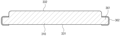
도 5는 도 4의 절단선 Ⅴ-Ⅴ에 따른 단면도5 is a cross-sectional view taken along the cutting line VV of FIG. 4.
도 6은 도 4의 절단선 Ⅵ-Ⅵ에 따른 단면도6 is a cross-sectional view taken along the cutting line VI-VI of FIG. 4.
도 7은 도 3의 절단선 Ⅶ-Ⅶ에 따른 단면도7 is a cross-sectional view taken along the line VII-VII of FIG. 3.
도 8 내지 도 10은 본 발명의 제 2 실시예의 구조를 도시한 것으로서,8 to 10 show the structure of the second embodiment of the present invention.
도 8은 방음부재의 사시도8 is a perspective view of the soundproof member
도 9는 도 8의 절단선 Ⅸ-Ⅸ에 따른 단면도9 is a cross-sectional view taken along the line VII-VII of FIG. 8.
도 10은 도 8의 절단선 Ⅹ-Ⅹ에 따른 단면도10 is a cross-sectional view taken along the line VII-VII of FIG. 8.
**도면의 주요부분에 대한 부호의 설명**** Description of the symbols for the main parts of the drawings **
300: 방음부재 310: 방음부재 본체300: soundproof member 310: soundproof member main body
320: 하단 밀폐돌부 330: 상단 밀폐돌부320: lower sealing protrusion 330: upper sealing protrusion
331: 전면 332: 후면331: front 332: rear
340: 상단 계단부 350: 하단 계단부340: upper stepped portion 350: lower stepped portion
본 발명은 방음부재에 관한 것으로서, 상세하게는 용이하게 착탈할 수 있을 뿐만 아니라, 소음의 밀폐효과가 뛰어난 방음부재에 관한 것이다.The present invention relates to a soundproof member, and more particularly, to a soundproof member that can be easily detached and has an excellent sealing effect of noise.
방음부재란 차로나 고가도로, 교량 등의 도로변에 설치되는 방음벽이나, 방음터널에 설치되는 것으로서, 도로를 주행하는 차량에 의해 발생하는 마찰음 및 경적소리 등의 소음을 감쇄시켜 주변지역의 전반적인 소음분포를 일정기준 이하로 낮추어주는 것을 말한다.Soundproof members are installed in soundproof walls or soundproof tunnels installed on roadsides, overpasses, bridges, etc., to reduce the noise of friction and horns generated by vehicles traveling on the road. It means lowering below a certain standard.
도 1 및 도 2는 종래의 방음부재의 구조를 도시한 것으로서, 도 1은 방음부재가 설치된 방음벽의 사시도, 도 2는 도 1의 Ⅱ부분의 확대 분해 사시도이다.1 and 2 show the structure of a conventional soundproofing member, FIG. 1 is a perspective view of a soundproof wall provided with a soundproofing member, and FIG. 2 is an enlarged exploded perspective view of part II of FIG. 1.
이들 도면에 도시된 바와 같이, 종래의 방음벽은 노상에 수직으로 설치된 복수의 메인 프레임(10)과, 메인 프레임(10) 사이에 설치되는 방음부재(20, 30)로 구성된다.As shown in these figures, the conventional soundproof wall is composed of a plurality of
메인 프레임(10)은 H형 빔을 수직으로 설치한 것으로서, 빔의 플랜지가 노상으로 향하도록 설치된다. 방음부재(20, 30)는 투명방음판(20) 이나 튜브형 방음판(30) 이나, 도시되어 있지는 않았지만, 방음판 등이 사용될 수 있다.The
이들의 설치방법은 도 2에 도시된 바와 같이, 방음부재 본체(31)의 측면에 돌출된 돌출결합부(32)를 메인 프레임(10)의 플랜지(11)와 플랜지(11) 사이에 끼워서 고정하는 것이다.As shown in FIG. 2, as shown in FIG. 2, the
이러한 방법을 사용하여 방음부재(30)를 메인 프레임(10)에 결합하는 경우, 방음구조물에 가해지는 풍하중 등에 견디는 결합력은 강하나, 각각의 부재를 조립 분해하는 것은 매우 어렵다.When the
예를 들면, 하부에 위치한 방음부재(30)에 손상이 발생한 경우, 손상이 발생한 방음부재(30)를 교체하기 위해서는, 상부에 위치한 방음부재(30)를 순차적으로 제거하여야 한다. 따라서, 유지보수를 위해서 많은 인력과, 비용, 시간이 소모되게 된다.For example, when damage occurs to the
본 발명은 상기와 같은 문제점을 해결하고자 안출된 것으로서, 용이하게 착탈할 수 있어 방음 구조물의 유지보수를 용이하게 하며, 소음의 밀폐 효과도 뛰어난 방음부재를 제공함을 그 목적으로 한다. The present invention has been made to solve the above problems, it can be easily removable to facilitate the maintenance of the soundproof structure, and to provide a soundproof member excellent in the sealing effect of noise.
본 발명은 상술한 바와 같은 목적을 달성하기 위하여, 방음부재 본체; 상기 방음부재 본체의 상단에 돌출 되어 형성된 상단 밀폐돌부; 상기 상단 밀폐돌부에서 상기 방음부재 본체 측으로 단이져 형성되며, 상기 상단 밀폐돌부의 반대방향으로 개방된 상단 계단부; 인접하여 설치된 방음부재의 상기 상단 계단부에 맞물리도록 밀폐돌부와 접하도록 상기 방음부재 본체의 하단에 돌출 되어 형성된 하단 밀폐돌부; 및 상기 상단 밀폐돌부와 맞물리도록 상기 하단 밀폐돌부에서 상기 방음부재 본체 측으로 단이져 형성되며, 상기 하단 밀폐돌부의 반대방향으로 개방된 하단 계단부; 를 포함하는 방음부재를 제공한다. 따라서, 용이하게 착탈할 수 있으며, 소음의 밀폐 효과도 뛰어나다.The present invention, in order to achieve the object as described above, the soundproof member body; An upper sealing protrusion protruding from an upper end of the soundproofing member main body; An upper stepped portion formed in the upper sealing protrusion to be stepped toward the soundproofing member main body and opened in an opposite direction of the upper sealing protrusion; A lower sealing protrusion protruding from a lower end of the soundproofing member main body to be in contact with the sealing protrusion so as to be engaged with the upper stepped portion of the soundproofing member adjacently installed; And a lower stepped portion formed in a step toward the soundproofing member main body from the lower sealing protrusion to be engaged with the upper sealing protrusion, and opened in the opposite direction of the lower sealing protrusion. It provides a soundproof member comprising a. Therefore, it can be attached and detached easily, and also excellent in the sealing effect of noise.
여기서, 상기 상단 밀폐돌부의 상단면 및 상기 상단 계단부의 상단면 중 적어도 어느 하나는 탄성재질로 이루어진 것이 바람직하다. 따라서, 밀폐 효과와 증대시킬 수 있을 뿐만 아니라, 착탈을 좀더 용이하게 할 수 있다.Here, at least one of the upper surface of the upper sealing protrusion and the upper surface of the upper stepped portion is preferably made of an elastic material. Therefore, not only the sealing effect can be increased, but also the attachment and detachment can be made easier.
그리고, 상기 상단 밀폐돌부의 상면과, 상기 상단 밀폐돌부와 상기 상단 계단부가 접하는 면, 사이에 위치한 모서리가 곡면으로 형성된 것이 효과적이다. 따라서, 착탈시 다른 방음부재에 걸리는 현상을 완화시켜 줄 수 있다.In addition, it is effective that the upper surface of the upper sealing protrusion, and the corner between the upper sealing protrusion and the upper stepped step, the corner formed between the curved surface. Therefore, it is possible to alleviate the phenomenon of the other sound-proof member when detached.
또한, 상기 방음부재 본체의 양측단에는 측면 결합부가 돌출 되어 형성된 것이 바람직하다. 따라서, 본체의 두께가 두꺼워져도 메인 프레임에서 돌출 되는 두께를 줄일 수 있다.In addition, it is preferable that both side ends of the soundproofing member main body are formed by protruding side engaging portions. Therefore, even if the thickness of the main body is thick, the thickness protruding from the main frame can be reduced.
여기서, 상기 측면 결합부를 감싸도록 설치된 보강부재를 더 포함하는 것이 바람직하다. 따라서, 측면 결합부의 두께를 더욱 얇게 형성할 수 있다.Here, it is preferable to further include a reinforcing member installed to surround the side coupling portion. Therefore, the thickness of the side engaging portion can be formed even thinner.
이하, 첨부도면을 참조하여 본 발명의 실시예에 관하여 상세히 설명한다.Hereinafter, embodiments of the present invention will be described in detail with reference to the accompanying drawings.
다만, 본 발명을 설명함에 있어서, 공지된 기능 혹은 구성에 대해 구체적인 설명이 본 발명의 요지를 흩트리지 않도록 하기 위하여 생략하기로 한다. 또한, 전술한 구성과 동일 및 동일 상당부분에 대해서는 동일한 참조부호를 부여하고, 그에 대한 상세한 설명은 생략하기로 한다.However, in describing the present invention, a detailed description of known functions or configurations will be omitted in order not to disturb the gist of the present invention. In addition, the same reference numerals are given to the same and the same components as those described above, and detailed description thereof will be omitted.
도 3 내지 도 7은 본 발명의 제 1 실시예의 구조를 도시한 도면으로서, 도 3 은 본 발명의 방음부재가 설치된 방음벽의 사시도, 도 4는 도 3의 방음부재의 사시도, 도 5는 도 4의 절단선 Ⅴ-Ⅴ에 따른 단면도, 도 6은 도 4의 절단선 Ⅵ-Ⅵ에 따른 단면도, 도 7은 도 3의 절단선 Ⅶ-Ⅶ에 따른 단면도이다.3 to 7 is a view showing the structure of the first embodiment of the present invention, Figure 3 is a perspective view of the soundproof wall is installed, the soundproof member of the present invention, Figure 4 is a perspective view of the soundproof member of Figure 3, Figure 5 is Figure 4 6 is a cross-sectional view taken along the cutting line VI-VI of FIG. 4, and FIG. 7 is a cross-sectional view taken along the cutting line VI-V of FIG. 3.
이들 도면에 도시된 바와 같이, 본 발명의 제 1 실시예의 방음부재는 방음부재 본체(310)와, 방음부재 본체(310)의 상단에 돌출 되어 형성된 상단 밀폐돌부(330)와, 상단 밀폐돌부(330)에서 계단져 형성된 상단 계단부(340)와, 방음부재 본체(310)의 하단에 돌출 되어 형성된 하단 밀폐돌부(320)와, 하단 밀폐돌부(320)에서 본체(310) 측으로 계단져 형성된 하단 계단부(350)와, 방음부재 본체(310)의 양측면에 돌출 되어 형성된 측면 결합부(361)로 구성된다.As shown in these drawings, the soundproofing member of the first embodiment of the present invention is the soundproofing member
방음부재 본체(310)는 흡음재, 방음판 등이 구비되어 소음을 저감시키는 역할을 하는 것으로서, 두께가 두텁게 형성된다.The soundproof member
상단 밀폐돌부(330)와 하단 계단부(350)는 방음부재(300)를 상하로 적층하였을 때, 맞물리도록 형성된다. 또한, 하단 밀폐돌부(320)는 방음부재(300)를 상하로 적층하였을 때, 상단 계단부(340)와 맞물리도록 형성된다. 또한, 상단 계단부(340)는 하단 밀폐돌부(320)를 바라보는 방향의 반대방향으로 개방되어 있다. 동일하게, 하단 계단부(350)는 상단 밀폐돌부(330)를 바라보는 방향의 반대방향으로 개방되어 있다.The
따라서, 도 5에 도시된 바와 같이, 방음부재의 상단 및 하단의 단면 형상이 계단 형상으로 형성되며, 상단 밀폐돌부(330)와 하단 밀폐돌부(320) 간에 하나의 측면에서 접하게 된다.Thus, as shown in Figure 5, the cross-sectional shape of the top and bottom of the soundproof member is formed in a stepped shape, the
그리고, 상단 밀폐돌부(330), 하단 밀폐돌부(320), 상단 계단부(340) 및 하단 계단부(350)의 끝면은 고무와 같은 탄성력이 있는 재질로 형성된다. 또한, 상단 밀폐돌부(330)의 상면과, 상단 밀폐돌부와 상단 계단부(340)가 접하는 면, 사이에 위치한 모서리(333)는 곡면으로 형성된다. 그리고, 상단 계단부(350)의 배면 측의 모서리(342), 즉 상단 계단부(350)의 상단 밀폐돌부의 반대측 모서리(342),도 곡면으로 형성되며, 하단 밀폐돌부(320)의 하단면과, 하단 밀폐돌부와 하단 계단부(350)가 접하는 면, 사이에 위치한 모서리(322)도 곡면으로 형성된다. 이는 방음벽 등에 결합된 방음부재의 착탈을 용이하게 하기 위한 것으로서, 착탈식 약간의 회전 공간의 여유를 주기 위함이다.The end surfaces of the
측면 결합부(361)는 본체(310)의 두께보다 얇게 형성되며, 보강부재(362)가 측면 결합부(361)를 감싸도록 결합된다. 보강부재(362)는 철판 등으로 형성될 수 있으며, 이외에도 다양한 재질로 형성될 수 있다. 그리고, 본 발명의 제 1 실시예에서는 보강부재(362)가 측면 결합부(361)를 감싸도록 형성되었으나, 소음원이 위치한 전면(331)이나 그 반대 방향인 배면(332)에만 위치하여도 무방하다.The
이하, 도 7을 참조하여 본 발명의 방음부재의 착탈방법을 설명한다.Hereinafter, a method of attaching and detaching the soundproof member of the present invention will be described with reference to FIG. 7.
먼저, 방음부재(300a)의 양 측면 결합부(361)가 메인 프레임(10)의 소음원을 바라보는 전면 플랜지(11a) 위에 위치시킨 후, 양 측면 결합부(361)를 전면 플랜지(10a)에 볼트 체결한다.First, both
그 다음 두 번째 방음부재(300b)의 하단 밀폐돌부(320)를 첫 번째 방음부재(300a)의 상단 계단부(340)에 삽입한 후, 첫 번째 방음부재(300a)와 동일한 방식으로 전면 플랜지(11a)에 결합한다.Then, the
세 번째 방음부재(300c)의 결합방법은 두 번째 방음부재(300b)와 동일하다.The coupling method of the
사용중 두 번째 방음부재(300b)가 손상되어 두 번째 방음부재(300b)를 수리하여야 하는 경우에는 다음과 같은 방법으로 할 수 있다.If the
먼저, 두 번째 방음부재(300b)와 전면 플랜지(11a)를 결합하고 있는 볼트를 해제한다.First, the bolt that couples the second
그 다음, 두 번째 방음부재(300b)를 화살표 방향으로 회전 시켜 메인 프레임(10)과 분리해낸다. 여기서, 곡면 모서리부(333, 342, 322)와, 탄성부재(321, 334, 341, 351)의해 두 번째 방음부재(300b)와 세 번째 방음부재(300c)간의 걸림을 방지할 수 있다.Then, the second
상기와 같이, 본 발명의 제 1 실시예의 방음부재는 상부에 설치된 다른 방음부재에 영향을 주지 않으며 쉽게 착탈할 수 있으므로, 유지보수가 용이하다.As described above, the soundproof member of the first embodiment of the present invention can be easily attached and detached without affecting other soundproof members installed on the upper portion, so that maintenance is easy.
그리고, 상단 밀폐돌부와 하단 밀폐돌부가 접하게 되어, 소음의 밀폐성이 뛰어난다는 장점도 있다.In addition, the upper sealing protrusion and the lower sealing protrusion is in contact, there is also an advantage that the noise sealing excellent.
도 8 내지 도 10은 본 발명의 제 2 실시예의 구조를 도시한 것으로서, 도 8은 방음부재의 사시도, 도 9는 도 8의 절단선 Ⅸ-Ⅸ에 따른 단면도, 도 10은 도 8의 절단선 Ⅹ-Ⅹ에 따른 단면도이다.8 to 10 show the structure of the second embodiment of the present invention, FIG. 8 is a perspective view of the soundproof member, FIG. 9 is a sectional view taken along the line VII-VII of FIG. 8, and FIG. 10 is a cutting line of FIG. It is sectional drawing according to VIII-VIII.
이들 도면에 도시된 바와 본 발명의 제 2 실시예의 방음부재는 투명방음판에 관한 것으로서 방음판(1310)과 방음판(1310)의 외주부를 지탱하는 방음판 프레임(1400)으로 이루어진다.As shown in these drawings, the soundproof member of the second embodiment of the present invention relates to a transparent soundproof plate, and includes a
방음판(1310)은 방음판 프레임(1400)의 거치턱(1425, 1435, 1442)과, 별도로 구비된 고정부재(1410) 사이에 끼워져 고정된다. The
본 발명의 특징은 방음판 프레임(1400)에 있는 것으로 이하에서는 방음판 프레임(1400)에 대해서 상술한다. A feature of the present invention resides in the
방음판 프레임(1400)은 상단 프레임(1420)과, 하단 프레임(1430)과 측면 프레임(1440)으로 구성된다.The sound
상단 프레임(1420)에는 상단 밀폐돌부(1421)가 돌출 되어 형성되며, 제 1 실시예와 동일하게 상단 계단부(1423)와, 곡면 모서리부(1422, 1424)가 형성된다. An
하단 프레임(1430)에는 하단 밀폐돌부(1431)가 돌출 되어 형성되며, 제 1 실시예와 동일하게 하단 계단부(1433)와, 곡면 모서리부(1432)가 형성된다.A
측면 프레임(1440)에는 측면 결합부(1441)가 돌출 되어 형성된다.The
전술한 바와 같이, 제 2 실시예의 방음부재 또한 착탈동작은 전술한 제 1 실시예와 동일하므로 이하에서 상세한 설명은 생략한다.As described above, the sound insulation member of the second embodiment is also attached and detached operation is the same as the above-described first embodiment, detailed description thereof will be omitted below.
이상에서 살펴본 바와 같은 본 발명의 실시예에 의하면 다음과 같은 사항을 포함하는 다양한 효과를 기대할 수 있다. 다만, 본 발명이 하기와 같은 효과를 모두 발휘해야 성립되는 것은 아니다.According to the embodiment of the present invention as described above, various effects including the following matters can be expected. However, the present invention is not achieved by exerting all of the following effects.
먼저, 본 발명에 따른 방음부재는 메인 프레임에 독립적으로 쉽게 착탈되므로, 유지보수가 용이하다.First, since the soundproof member according to the present invention is easily detached from the main frame, maintenance is easy.
또한, 상단 밀폐돌부 및 하단 밀폐돌부를 구비함으로써, 방음효과가 뛰어나다. In addition, by providing an upper closed protrusion and a lower closed protrusion, the soundproofing effect is excellent.
그리고, 상단 밀폐돌부 및 하단 밀폐돌부의 일부가 탄성력 있는 재질로 형성됨으로써, 착탈이 훨씬 용이하다.And, since the upper part of the sealing protrusion and the lower part of the sealing protrusion is formed of an elastic material, detachment is much easier.
이상에서는 본 발명의 바람직한 실시예를 예시적으로 설명하였으나, 본 발명의 범위는 이와 같은 특정 실시예에만 한정되는 것은 아니며, 특허청구범위에 기재된 범주 내에서 적절하게 변경 가능한 것이다. Although the preferred embodiments of the present invention have been described above by way of example, the scope of the present invention is not limited to these specific embodiments, and may be appropriately changed within the scope described in the claims.
Claims (19)
Priority Applications (1)
| Application Number | Priority Date | Filing Date | Title |
|---|---|---|---|
| KR1020040069458A KR100654281B1 (en) | 2004-09-01 | 2004-09-01 | Sound insulation |
Applications Claiming Priority (1)
| Application Number | Priority Date | Filing Date | Title |
|---|---|---|---|
| KR1020040069458A KR100654281B1 (en) | 2004-09-01 | 2004-09-01 | Sound insulation |
Publications (2)
| Publication Number | Publication Date |
|---|---|
| KR20060020786A KR20060020786A (en) | 2006-03-07 |
| KR100654281B1 true KR100654281B1 (en) | 2006-12-08 |
Family
ID=37127806
Family Applications (1)
| Application Number | Title | Priority Date | Filing Date |
|---|---|---|---|
| KR1020040069458A Expired - Fee Related KR100654281B1 (en) | 2004-09-01 | 2004-09-01 | Sound insulation |
Country Status (1)
| Country | Link |
|---|---|
| KR (1) | KR100654281B1 (en) |
Cited By (2)
| Publication number | Priority date | Publication date | Assignee | Title |
|---|---|---|---|---|
| KR101034007B1 (en) * | 2010-06-29 | 2011-05-11 | 주식회사 태건 | How to install soundproof tunnel and soundproof tunnel |
| KR101438649B1 (en) * | 2012-11-06 | 2014-09-12 | 에스에이 주식회사 | Soundproofed wall having concrete support |
Families Citing this family (2)
| Publication number | Priority date | Publication date | Assignee | Title |
|---|---|---|---|---|
| KR200459917Y1 (en) * | 2009-11-12 | 2012-04-20 | 주식회사 유니엠 | Repairing panel of soundproof wall and the repaired soundproof wall |
| KR101587382B1 (en) | 2015-05-26 | 2016-01-20 | (주)엠에스로드 | sound proof wall |
Citations (4)
| Publication number | Priority date | Publication date | Assignee | Title |
|---|---|---|---|---|
| KR960010082Y1 (en) * | 1993-04-09 | 1996-11-22 | 포산금속 주식회사 | Soundproof Wall Panel |
| KR970049937U (en) * | 1996-01-12 | 1997-08-12 | 태장금속공업주식회사 | Transparent soundproof board for soundproof wall |
| JP2001193020A (en) | 2000-01-14 | 2001-07-17 | Sekisui Jushi Co Ltd | Soundproof panel |
| KR100324211B1 (en) | 1998-09-21 | 2002-07-02 | (주)건우사종합건축사사무소 | Noise protection block and noise protection wall using the block |
-
2004
- 2004-09-01 KR KR1020040069458A patent/KR100654281B1/en not_active Expired - Fee Related
Patent Citations (4)
| Publication number | Priority date | Publication date | Assignee | Title |
|---|---|---|---|---|
| KR960010082Y1 (en) * | 1993-04-09 | 1996-11-22 | 포산금속 주식회사 | Soundproof Wall Panel |
| KR970049937U (en) * | 1996-01-12 | 1997-08-12 | 태장금속공업주식회사 | Transparent soundproof board for soundproof wall |
| KR100324211B1 (en) | 1998-09-21 | 2002-07-02 | (주)건우사종합건축사사무소 | Noise protection block and noise protection wall using the block |
| JP2001193020A (en) | 2000-01-14 | 2001-07-17 | Sekisui Jushi Co Ltd | Soundproof panel |
Cited By (2)
| Publication number | Priority date | Publication date | Assignee | Title |
|---|---|---|---|---|
| KR101034007B1 (en) * | 2010-06-29 | 2011-05-11 | 주식회사 태건 | How to install soundproof tunnel and soundproof tunnel |
| KR101438649B1 (en) * | 2012-11-06 | 2014-09-12 | 에스에이 주식회사 | Soundproofed wall having concrete support |
Also Published As
| Publication number | Publication date |
|---|---|
| KR20060020786A (en) | 2006-03-07 |
Similar Documents
| Publication | Publication Date | Title |
|---|---|---|
| KR101027873B1 (en) | Glass Plate Fixture on Elevator Door | |
| KR200485826Y1 (en) | A Combination structure of attachable and detachable type soundproof board and soundproof panel | |
| KR102044345B1 (en) | Load-spreading soundproof wall and replacementing method thereof | |
| KR20190050389A (en) | A Soundproofing panel fixing structure for soundproof tunnel | |
| JP7481931B2 (en) | Sound insulation wall and sound insulation panel used therein | |
| KR101765090B1 (en) | a temporary soundproofing walls | |
| KR20170123792A (en) | Noise-proof panel | |
| KR102273816B1 (en) | Multi type soundproofpanel | |
| KR20060020786A (en) | Sound insulation | |
| KR102142192B1 (en) | Frame structure for soundproofing plate and sounfproofing panel using the same | |
| KR100989890B1 (en) | Soundproofing panel | |
| CN215629521U (en) | Assembled sound barrier structure | |
| KR100507751B1 (en) | A soundproof plate fixing device | |
| KR20130084085A (en) | Comprehensive type soundproofing pannel assembly | |
| KR20190048277A (en) | Sound proof wall | |
| KR101419264B1 (en) | a soundproof with sound plate for incline hookup | |
| KR101914092B1 (en) | Fixing equipments for soundproof panel of noise barrier tunnel | |
| KR102265837B1 (en) | Sound Insulation and Sound Absorption Composite Soundproof plates for easy maintenance using removal of the upper frame and their construction and maintenance methods | |
| KR20160043284A (en) | A transparent soundproof frame assembly | |
| JPH09203278A (en) | Door panel framework | |
| JPH07150524A (en) | Sound insulating wall | |
| KR102272087B1 (en) | Maintenance-repair type sound proof wall | |
| KR102119837B1 (en) | Road soundproof walls and soundproof tunnel struts | |
| KR102207776B1 (en) | Soundproofing facilities equiped with light weight circular props | |
| KR20200048556A (en) | Transparent sound insulation plate with detachable structure |
Legal Events
| Date | Code | Title | Description |
|---|---|---|---|
| A201 | Request for examination | ||
| PA0109 | Patent application |
St.27 status event code: A-0-1-A10-A12-nap-PA0109 |
|
| PA0201 | Request for examination |
St.27 status event code: A-1-2-D10-D11-exm-PA0201 |
|
| D13-X000 | Search requested |
St.27 status event code: A-1-2-D10-D13-srh-X000 |
|
| D14-X000 | Search report completed |
St.27 status event code: A-1-2-D10-D14-srh-X000 |
|
| PG1501 | Laying open of application |
St.27 status event code: A-1-1-Q10-Q12-nap-PG1501 |
|
| E902 | Notification of reason for refusal | ||
| PE0902 | Notice of grounds for rejection |
St.27 status event code: A-1-2-D10-D21-exm-PE0902 |
|
| T11-X000 | Administrative time limit extension requested |
St.27 status event code: U-3-3-T10-T11-oth-X000 |
|
| T11-X000 | Administrative time limit extension requested |
St.27 status event code: U-3-3-T10-T11-oth-X000 |
|
| E13-X000 | Pre-grant limitation requested |
St.27 status event code: A-2-3-E10-E13-lim-X000 |
|
| P11-X000 | Amendment of application requested |
St.27 status event code: A-2-2-P10-P11-nap-X000 |
|
| P13-X000 | Application amended |
St.27 status event code: A-2-2-P10-P13-nap-X000 |
|
| E701 | Decision to grant or registration of patent right | ||
| PE0701 | Decision of registration |
St.27 status event code: A-1-2-D10-D22-exm-PE0701 |
|
| GRNT | Written decision to grant | ||
| PR0701 | Registration of establishment |
St.27 status event code: A-2-4-F10-F11-exm-PR0701 |
|
| PR1002 | Payment of registration fee |
Fee payment year number: 1 St.27 status event code: A-2-2-U10-U11-oth-PR1002 |
|
| PG1601 | Publication of registration |
St.27 status event code: A-4-4-Q10-Q13-nap-PG1601 |
|
| PR1001 | Payment of annual fee |
Fee payment year number: 4 St.27 status event code: A-4-4-U10-U11-oth-PR1001 |
|
| FPAY | Annual fee payment |
Payment date: 20110527 Year of fee payment: 5 |
|
| PR1001 | Payment of annual fee |
Fee payment year number: 5 St.27 status event code: A-4-4-U10-U11-oth-PR1001 |
|
| LAPS | Lapse due to unpaid annual fee | ||
| PC1903 | Unpaid annual fee |
Not in force date: 20111130 Payment event data comment text: Termination Category : DEFAULT_OF_REGISTRATION_FEE St.27 status event code: A-4-4-U10-U13-oth-PC1903 |
|
| R18-X000 | Changes to party contact information recorded |
St.27 status event code: A-5-5-R10-R18-oth-X000 |
|
| PC1903 | Unpaid annual fee |
Ip right cessation event data comment text: Termination Category : DEFAULT_OF_REGISTRATION_FEE Not in force date: 20111130 St.27 status event code: N-4-6-H10-H13-oth-PC1903 |
|
| P22-X000 | Classification modified |
St.27 status event code: A-4-4-P10-P22-nap-X000 |
|
| R18-X000 | Changes to party contact information recorded |
St.27 status event code: A-5-5-R10-R18-oth-X000 |
|
| P22-X000 | Classification modified |
St.27 status event code: A-4-4-P10-P22-nap-X000 |
|
| R18-X000 | Changes to party contact information recorded |
St.27 status event code: A-5-5-R10-R18-oth-X000 |
|
| R18-X000 | Changes to party contact information recorded |
St.27 status event code: A-5-5-R10-R18-oth-X000 |
|
| PN2301 | Change of applicant |
St.27 status event code: A-5-5-R10-R11-asn-PN2301 St.27 status event code: A-5-5-R10-R13-asn-PN2301 |